US8439957B2 - Bone plate assembly provided with screw locking mechanisms - Google Patents
Bone plate assembly provided with screw locking mechanismsDownload PDFInfo
- Publication number
- US8439957B2 US8439957B2US13/316,224US201113316224AUS8439957B2US 8439957 B2US8439957 B2US 8439957B2US 201113316224 AUS201113316224 AUS 201113316224AUS 8439957 B2US8439957 B2US 8439957B2
- Authority
- US
- United States
- Prior art keywords
- region
- washer
- bone
- bone screw
- aperture
- Prior art date
- Legal status (The legal status is an assumption and is not a legal conclusion. Google has not performed a legal analysis and makes no representation as to the accuracy of the status listed.)
- Expired - Fee Related
Links
Images


Classifications
- A—HUMAN NECESSITIES
- A61—MEDICAL OR VETERINARY SCIENCE; HYGIENE
- A61B—DIAGNOSIS; SURGERY; IDENTIFICATION
- A61B17/00—Surgical instruments, devices or methods
- A61B17/56—Surgical instruments or methods for treatment of bones or joints; Devices specially adapted therefor
- A61B17/58—Surgical instruments or methods for treatment of bones or joints; Devices specially adapted therefor for osteosynthesis, e.g. bone plates, screws or setting implements
- A61B17/68—Internal fixation devices, including fasteners and spinal fixators, even if a part thereof projects from the skin
- A61B17/84—Fasteners therefor or fasteners being internal fixation devices
- A61B17/86—Pins or screws or threaded wires; nuts therefor
- A61B17/8605—Heads, i.e. proximal ends projecting from bone
- A61B17/861—Heads, i.e. proximal ends projecting from bone specially shaped for gripping driver
- A61B17/8615—Heads, i.e. proximal ends projecting from bone specially shaped for gripping driver at the central region of the screw head
- A—HUMAN NECESSITIES
- A61—MEDICAL OR VETERINARY SCIENCE; HYGIENE
- A61B—DIAGNOSIS; SURGERY; IDENTIFICATION
- A61B17/00—Surgical instruments, devices or methods
- A61B17/56—Surgical instruments or methods for treatment of bones or joints; Devices specially adapted therefor
- A61B17/58—Surgical instruments or methods for treatment of bones or joints; Devices specially adapted therefor for osteosynthesis, e.g. bone plates, screws or setting implements
- A61B17/68—Internal fixation devices, including fasteners and spinal fixators, even if a part thereof projects from the skin
- A61B17/80—Cortical plates, i.e. bone plates; Instruments for holding or positioning cortical plates, or for compressing bones attached to cortical plates
- A61B17/8033—Cortical plates, i.e. bone plates; Instruments for holding or positioning cortical plates, or for compressing bones attached to cortical plates having indirect contact with screw heads, or having contact with screw heads maintained with the aid of additional components, e.g. nuts, wedges or head covers
- A61B17/8042—Cortical plates, i.e. bone plates; Instruments for holding or positioning cortical plates, or for compressing bones attached to cortical plates having indirect contact with screw heads, or having contact with screw heads maintained with the aid of additional components, e.g. nuts, wedges or head covers the additional component being a cover over the screw head
- A—HUMAN NECESSITIES
- A61—MEDICAL OR VETERINARY SCIENCE; HYGIENE
- A61B—DIAGNOSIS; SURGERY; IDENTIFICATION
- A61B17/00—Surgical instruments, devices or methods
- A61B17/56—Surgical instruments or methods for treatment of bones or joints; Devices specially adapted therefor
- A61B17/58—Surgical instruments or methods for treatment of bones or joints; Devices specially adapted therefor for osteosynthesis, e.g. bone plates, screws or setting implements
- A61B17/68—Internal fixation devices, including fasteners and spinal fixators, even if a part thereof projects from the skin
- A61B17/80—Cortical plates, i.e. bone plates; Instruments for holding or positioning cortical plates, or for compressing bones attached to cortical plates
- A61B17/8033—Cortical plates, i.e. bone plates; Instruments for holding or positioning cortical plates, or for compressing bones attached to cortical plates having indirect contact with screw heads, or having contact with screw heads maintained with the aid of additional components, e.g. nuts, wedges or head covers
- A61B17/8047—Cortical plates, i.e. bone plates; Instruments for holding or positioning cortical plates, or for compressing bones attached to cortical plates having indirect contact with screw heads, or having contact with screw heads maintained with the aid of additional components, e.g. nuts, wedges or head covers wherein the additional element surrounds the screw head in the plate hole
- A—HUMAN NECESSITIES
- A61—MEDICAL OR VETERINARY SCIENCE; HYGIENE
- A61B—DIAGNOSIS; SURGERY; IDENTIFICATION
- A61B17/00—Surgical instruments, devices or methods
- A61B17/56—Surgical instruments or methods for treatment of bones or joints; Devices specially adapted therefor
- A61B17/58—Surgical instruments or methods for treatment of bones or joints; Devices specially adapted therefor for osteosynthesis, e.g. bone plates, screws or setting implements
- A61B17/68—Internal fixation devices, including fasteners and spinal fixators, even if a part thereof projects from the skin
- A61B17/80—Cortical plates, i.e. bone plates; Instruments for holding or positioning cortical plates, or for compressing bones attached to cortical plates
- A61B17/8052—Cortical plates, i.e. bone plates; Instruments for holding or positioning cortical plates, or for compressing bones attached to cortical plates immobilised relative to screws by interlocking form of the heads and plate holes, e.g. conical or threaded
- A—HUMAN NECESSITIES
- A61—MEDICAL OR VETERINARY SCIENCE; HYGIENE
- A61B—DIAGNOSIS; SURGERY; IDENTIFICATION
- A61B17/00—Surgical instruments, devices or methods
- A61B17/56—Surgical instruments or methods for treatment of bones or joints; Devices specially adapted therefor
- A61B17/58—Surgical instruments or methods for treatment of bones or joints; Devices specially adapted therefor for osteosynthesis, e.g. bone plates, screws or setting implements
- A61B17/68—Internal fixation devices, including fasteners and spinal fixators, even if a part thereof projects from the skin
- A61B17/84—Fasteners therefor or fasteners being internal fixation devices
- A61B17/86—Pins or screws or threaded wires; nuts therefor
- A61B17/8605—Heads, i.e. proximal ends projecting from bone
- A—HUMAN NECESSITIES
- A61—MEDICAL OR VETERINARY SCIENCE; HYGIENE
- A61B—DIAGNOSIS; SURGERY; IDENTIFICATION
- A61B17/00—Surgical instruments, devices or methods
- A61B17/56—Surgical instruments or methods for treatment of bones or joints; Devices specially adapted therefor
- A61B17/58—Surgical instruments or methods for treatment of bones or joints; Devices specially adapted therefor for osteosynthesis, e.g. bone plates, screws or setting implements
- A61B17/68—Internal fixation devices, including fasteners and spinal fixators, even if a part thereof projects from the skin
- A61B17/84—Fasteners therefor or fasteners being internal fixation devices
- A61B17/86—Pins or screws or threaded wires; nuts therefor
- A61B17/8625—Shanks, i.e. parts contacting bone tissue
- A61B17/863—Shanks, i.e. parts contacting bone tissue with thread interrupted or changing its form along shank, other than constant taper
- A—HUMAN NECESSITIES
- A61—MEDICAL OR VETERINARY SCIENCE; HYGIENE
- A61B—DIAGNOSIS; SURGERY; IDENTIFICATION
- A61B17/00—Surgical instruments, devices or methods
- A61B17/56—Surgical instruments or methods for treatment of bones or joints; Devices specially adapted therefor
- A61B17/58—Surgical instruments or methods for treatment of bones or joints; Devices specially adapted therefor for osteosynthesis, e.g. bone plates, screws or setting implements
- A61B17/68—Internal fixation devices, including fasteners and spinal fixators, even if a part thereof projects from the skin
- A61B17/84—Fasteners therefor or fasteners being internal fixation devices
- A61B17/86—Pins or screws or threaded wires; nuts therefor
- A61B17/8685—Pins or screws or threaded wires; nuts therefor comprising multiple separate parts
Definitions
- One embodiment of the present inventionis directed to a bone plate assembly that includes a bone plate, bone screw(s) received in aperture(s) in the bone plate, and screw fixation member(s).
- the screw fixation member(s)may, alone or in conjunction with the bone plate, fix the bone screw(s) in place when such bone screw(s) are inserted in the aperture(s) in the bone plate.
- the bone plate assemblycan be used to fuse anatomical structures together (such as adjoining bones) and/or to heal a fracture in bone.
- Bone plate assembliesare employed in order to fuse bones or to repair fractures in bones.
- U.S. Pat. No. 6,413,259incorporated herein by reference, discloses embodiments for bone plates.
- the present inventionis directed to an arrangement for fixing, in a vertebrate, a screw inserted through a plate.
- a bone plate assembly according to the present inventionmay have at least two bone screws, each received in at least two apertures in the bone plate.
- the bone plate assemblymay also have screw fixation members provided for the bone screws. When the bone screws are inserted through the apertures in the bone plate, and installed in bone and/or tissue at a preselected angle, the presence of the screw fixation members may aid in fixing the bone screws in place.
- Each bone screwmay have a head, sized so that the head does not pass through the bone plate, and a shank provided with threads (e.g., which threads may extend substantially to the tip of the bone screw).
- the bone plate assemblymay be provided with washers (e.g., for each screw employed in the assembly) that reside in the apertures in the bone plate.
- each washermay be provided with an aperture in which the bone screw is received, when the bone screw is inserted into the bone plate.
- the washermay be actuated to fix the angle at which the bone screw has been inserted (e.g., relative to the bone plate).
- the washermay be provided with a sidewall, which sidewall defines the aperture though which the bone screw extends.
- the sidewallmay have a thickness that varies with respect to the position along the washer's perimeter.
- the washermay be provided with a first sidewall region on its perimeter that is relatively thicker than a second sidewall region.
- one or more apertures of the bone platemay be provided with a recess that is cut into the sidewall that defines the aperture in the bone plate.
- the depth to which the recess is cutmay vary around the perimeter of the recess.
- a first region of the recessmay have a depth that is greater than a second region of the recess.
- a washermay reside partially or fully within the recess.
- the washermay reside in the recess, aligned so that the first relatively thicker sidewall region of the washer is positioned within the first relatively deeper region of the recess, and the second relatively thinner sidewall region of the washer is positioned in the second relatively shallower region of the recess.
- the bone screwmay be fixed by rotating the washer, thereby moving the first relatively thicker sidewall region of the washer into the second relatively shallower region of the recess, which effectively causes the first relatively thicker sidewall region to extend laterally, into the aperture in the bone plate, where the washer impinges against the bone screw (e.g., the head of the bone screw), applying a force thereto which wedges the bone screw between the washer and the opposite sidewall of the aperture.
- This operationthus fixes the bone screw in place, retaining it at a particular angle (e.g., the at which the bone screw is inserted).
- the present inventionmay allow for the bone screw(s) to toggle (i.e., move within a confined range) after being installed through the bone plate and being held by the washer. This can be arranged, for example, by actuating the washer to an intermediate position, which allows the screw to toggle.
- a bone plate assemblymay be provided in which the bone plate assembly may include a bone plate, bone screw(s) received in aperture(s) in the bone plate, and washer(s).
- the washer(s)may, alone or in conjunction with the bone plate, fix the bone screw(s) in place when the bone screw(s) are inserted in the aperture(s) in the bone plate.
- the washer of the bone plate assemblymay be adapted to reside over the bone screw and be joined therewith in a locking arrangement.
- the head of the bone screwmay be provided with a number of tangs, spaced apart from each other, mounted on the upper surface of the head. The tangs may be mounted upon wedges, which wedges extend up from the head of the screw. The wedges may be not as wide as the tangs, and may be narrowed by an undercut.
- the washermay be provided with a washer body through which a central opening is provided.
- a number of lobesmay be provided on the periphery of the central opening.
- three lobesare provided (it should be understood that other arrangements are, of course, possible).
- the washermay also be provided with splays which are provided on the exterior of the washer. The splays may be separated from the remainder of the washer body by tracks, which tracks extend into the washer body.
- the washer and the wedges and/or tangsmay be designed to engage with each other in a locking arrangement. Relative to each other, the wedges may be slightly wider than the width of at least a portion of the track.
- the bone platewhen the bone plate assembly is implanted in a person, the bone plate may be positioned on the bone, tissue and bone, or tissue to be joined by the bone plate.
- the bone screwmay be inserted through the aperture in the bone plate and installed in bone and/or tissue by known techniques.
- the bone screwmay be installed at a preselected angle, relative to the bone plate.
- the washermay be placed over the head of the bone screw, and positioned so that the wedges are poised to enter the track portions.
- a toolmay be provided, the tool having a head adapted to fit within the central washer opening, which tool then engages with the central washer opening, to rotate the washer. The wedges may thereby enter the track portions.
- the splaysmay be forced outward when the wedges enter the intermediate track portion(s).
- the splaysmay be forced into an abutting arrangement with the sidewalls of the aperture in which the bone screw and washer reside.
- the abutting arrangement between the splays and the sidewalls of the aperturemay fix the bone screw at a particular angle (e.g., the angle at which the bone screw was installed).
- a bone plate assemblymay be generally provided with a bone plate, at least two bone screws received in apertures in the bone plate, and moveable doors that fix the bone screws in place when the bone screws are inserted in the apertures in the bone plate.
- the bone screw employed in this embodimentmay have a head sized so that the head does not pass through the bone plate.
- the bone screwmay further have a shank provided with threads (e.g., which threads may that extend to the tip of the bone screw).
- the bone plate assemblymay be provided with a cut out portion on its upper surface, to which the doors are slidably mounted. The cut out portion may be positioned adjacent the bone screw apertures, at a portion of the edge thereof.
- the sliding doorsmay be dimensioned to substantially not cover the apertures in the bone plate in a first position (in which first position the bone screws may be installed), yet slide and at least partially cover the apertures once the screws have been inserted (to thereby fix the bone screws in place).
- the doorsmay be positioned in the cut out portion on the upper surface of the bone plate, and may be retained therein by a lip provided at the upper sidewall of the cut out portion.
- the cut out portionmay be sized slightly greater than the sliding doors.
- a bone screwmay be provided with a number of splays positioned around the periphery of the head of the bone screw.
- the splaysmay be mounted upon wedges that extend up from the head of the screw.
- a toolmay be employed to force the splays outward, into a locking and abutting arrangement with the sidewalls of the bone plate aperture.
- a cammay be positioned in the interior space defined by the splays.
- the camWhen the cam is rotated, the cam may force the splays outward, into a locking and abutting arrangement with the sidewalls of the bone plate aperture.
- the presence of the cammay further provide a counterforce, which counterforce may maintain the splays in the locking and abutting arrangement.
- FIG. 1is a perspective view of an embodiment of the present invention
- FIG. 2is a top plan view of the embodiment of FIG. 1 ;
- FIG. 3Ais a cross sectional view of the embodiment of FIG. 1 ;
- FIG. 3Bis a cross sectional view showing in greater detail the circled portion of FIG. 3A ;
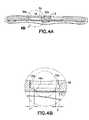
- FIG. 4Ais a cross sectional view of the bone plate of the embodiment of FIG. 1 (shown across the long side);
- FIG. 4Bis a cross sectional view showing in greater detail the circled portion of FIG. 4A ;
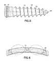
- FIG. 5is a side elevational view of a screw employed in the embodiment of FIG. 1 ;
- FIG. 6is a cross sectional view of the bone plate of the embodiment of FIG. 1 (shown across the short side);
- FIG. 7Ais a top plan view of a washer used in an embodiment of the present invention.
- FIG. 7Bis a perspective view of the washer of FIG. 7A ;
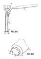
- FIG. 8Ais a cross-sectional view of a tool used in conjunction with the embodiment of FIG. 1 ;
- FIG. 8Bis a perspective view of a portion of the tool of FIG. 8A ;
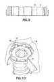
- FIG. 9is a cross sectional view of the washer of FIG. 7A ;
- FIG. 10is a partially sectioned perspective view of a portion of the embodiment of FIG. 1 ;
- FIG. 11is a partially sectioned view showing an the undercut or recess in connection with the embodiment of FIG. 1 ;
- FIG. 12Adepicts the washer of FIG. 7A in the open or unactuated position
- FIG. 12Bdepicts the washer of FIG. 7A in the closed or actuated position
- FIG. 13is a partially sectioned perspective view of another embodiment of the present invention.
- FIG. 14is a perspective view of a washer and screw of the embodiment of FIG. 13 ;
- FIG. 15is a perspective view of the washer of the embodiment of FIG. 13 ;
- FIG. 16is a top plan view showing in greater detail an aspect of the washer of the embodiment of FIG. 13 ;
- FIG. 17is a top plan view of the screw of the embodiment of FIG. 13 ;
- FIG. 18is a side elevational view of the screw of the embodiment of FIG. 13 ;
- FIG. 19is a perspective view of the screw of the embodiment of FIG. 13 ;
- FIG. 20is a cross sectional view of the washer and screw of the embodiment of FIG. 13 ;
- FIG. 21is a perspective view of the embodiment of FIG. 13 , where the washer has been opened;
- FIG. 22Ais a top plan view of another embodiment of the present invention.
- FIG. 22Bis a perspective view of the embodiment of FIG. 22A ;
- FIG. 22Cis cross sectional view of the embodiment of FIG. 22A ;
- FIG. 23is a perspective view of another embodiment of the present invention.
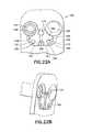
- FIG. 24is top plan view of the embodiment of FIG. 23 ;
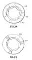
- FIG. 25is a cross sectional view of the embodiment of FIG. 23 ;
- FIG. 26is a side elevational view of the embodiment of FIG. 23 ;
- FIG. 27is a perspective view of the embodiment of FIG. 23 ;
- FIG. 28depicts another embodiment of the present invention.
- FIG. 29depicts, in a perspective view, another embodiment in which a double lobed washer is employed.
- FIG. 30depicts, in a perspective view, another embodiment in which a tri-lobed washer is employed.
- FIG. 31depicts, in a perspective view, a split-ring washer according to another embodiment of the present invention.
- a bone plate assembly 10is provided with bone plate 12 , bone screw(s) 14 received in aperture(s) 16 in the bone plate 12 , and washer(s) 18 that, alone or in conjunction with the bone plate 12 , fix the bone screw(s) 14 in place (e.g., when the bone screw(s) 14 are inserted in the aperture(s) 16 in the bone plate).
- Each bone screw 14has a head 20 sized so that it does not pass through the bone plate 12 .
- each bone screw 14has a shank 22 provided with threads 24 (e.g., which threads 24 may extend to tip 26 ).
- the head 20 of bone screw 14is further provided with an opening 15 that is dimensioned to mate with the head of a tool, so that the bone screw 14 can be installed in tissue and/or bone.
- the head 20 of the bone screw 14may be provided with grooves 21 (see, e.g., FIGS. 3B and 5 ).
- Bone plate assembly 10is also provided with washer(s) 18 . Each washer 18 has an opening 19 though which a bone screw is received (see, e.g., FIG. 3B ).
- each washer 18is provided with a sidewall 28 (which sidewall 28 defines the aperture 19 though which the bone screw extends) and that the sidewall 28 has a varying thickness with respect to position along the washer's perimeter (see also, for example, FIG. 7A ).
- the washer 18is provided with a first sidewall region 28 a that is relatively thicker than a second sidewall region 28 b (i.e., in this embodiment dimension “a” is greater than dimension “b” (see FIG. 3B )).
- the washermay be provided with a series of splines 31 that are spaced at intervals around the inside perimeter of the washer (the washer of FIG. 31 is similar to the washers of FIGS. 7A , 7 B, 8 A, 8 B and 9 , with the exception that the washer of FIG. 31 is a split-ring washer).
- the splinesmay be solid members (which may extend from the perimeter of the washer towards the aperture 19 of the washer), and may be spaced apart by openings 32 .
- the arrangement of the splines 31 and openings 32may be complementary to a spline 41 and opening 42 arrangement provided on the head 44 of a tool 40 (see, e.g., FIGS. 8A and 8B ).
- a tool 40see, e.g., FIGS. 8A and 8B .
- the toolmay, for example, be operated manually by handle 43 , or by drill, in which case drill bit receiving channel 45 may be provided.
- the washer 18may be provided with a detent 50 positioned on the outside of the sidewall 28 .
- the sidewall of the bone platemay be provided with an indentation 52 , which is sized to receive the detent provided on the washer 18 (see, e.g., FIG. 10 ).
- the washercan be aligned so that the detent 50 resides in the indentation 52 . This arrangement may inhibit unwanted rotation of the washer (e.g., until the time to actuate it, as described below).
- bone plate 12may be constructed with an arcuate shape.
- plates with other shapes and/or dimensionsare possible.
- bone plate 12may be provided with one or more recesses 30 , positioned within the bone plate 12 (see FIGS. 4A , 4 B, 5 and 6 ). Each recess 30 may extend around the perimeter of each aperture 16 in the bone plate 12 . Each recess 30 may be cut into the sidewall of the apertures in the bone plate 12 . The lateral depth to which each recess 30 is cut may vary depending on the location on the perimeter of the recess 30 .
- a first region 30 a of the recess 30may have a lateral depth that is greater than the lateral depth of a second region 30 b of the recess 30 (i.e., in this embodiment dimension “a” is greater than dimension “b” (see FIG. 4B )).
- the lower portion of aperture 16may be provided with a tapered sidewall 16 a against which the bottom portion of the screw head 20 may rest (see FIG. 4B ).
- the washer 18may reside within the recess, aligned so that the first relatively thicker sidewall region 28 a of the washer 18 is positioned within the first relatively deeper region 30 a of the recess, and the second relatively thinner sidewall region 28 b of the washer 18 is positioned in the second relatively shallower region 30 b of the recess.
- the washer 18when the bone screw 14 is inserted into the aperture 16 of the bone plate 12 , the washer 18 is substantially coplanar with the head 20 of the bone screw 14 .
- the lateral depth of the second recess region 30 bmay be minimal (and may not be present at all) and a lateral depth may be provided essentially only in the first recess region 30 a.
- FIGS. 12A and 12Bit is seen that when the bone plate assembly is implanted in a person, the bone plate is positioned over the bone, bones, and/or tissue to be joined by the bone plate 12 .
- the bone screw(s)are inserted through the aperture(s) in the washer(s) (which washer(s) may reside in the recess(s) provided in the aperture(s) of the bone plate) and the bone screw(s) are installed in bone and/or tissue by known techniques.
- Each bone screwmay be installed at a preselected angle, relative to the bone plate.
- the bone screwmay pass through the opening in the washer (e.g., so that the bone screw may be installed at a preselected angle) (see FIG. 12A ).
- the washermay be actuated by rotating the washer (e.g., with the tool, as described above).
- the first relatively thicker sidewall region of the washermay move into the second relatively shallower region of the recess.
- FIGS. 10 and 12Bdepict the condition where the bone screw is wedged after actuating the washer.
- FIGS. 13-21another bone plate assembly is depicted. Shown here is a bone plate, bone screw, and a washer. With this arrangement, a bone plate that does not have a recess can be employed with this screw and washer pairing.
- FIG. 13depicts a bone plate assembly 100 , generally provided with bone plate 102 , bone screw(s) 104 received in aperture(s) 106 in the bone plate 102 , and washer(s) 108 that, alone or in conjunction with the bone plate 102 , fix the bone screw(s) 104 in place (i.e., when the bone screw(s) 104 are inserted in the aperture(s) 106 in the bone plate 102 ).
- Each bone screw 104has a head 110 sized so that it does not pass through the bone plate 102 .
- each bone screw 104has a shank 112 provided with threads 114 (e.g., which threads 114 extend to tip 116 ).
- each bone screw 104may be provided with grooves 118 (see, e.g., FIGS. 4 and 5C ).
- Bone plate assembly 100is provided with washer(s) 108 , each of which (as described below) is adapted to reside over a bone screw 104 and be joined therewith in a locking arrangement.
- the head 110 of bone screw 104is provided with a number of tangs 120 , spaced apart from each other, mounted on the upper surface of the head 110 .
- the tangs 120include wedges 122 , which wedges 122 are not as wide as the upper portions of the tangs 120 (the wedges 122 are 5 narrowed by an undercut).
- the head 110is provided with an opening 107 in which a tool can be received to apply a rotational force, which rotational force permits the installation of the screw in tissue and/or bone.
- Each washer 108is sized and dimensioned to fit within one of the aperture(s) 106 in the bone plate 102 .
- Each washer 108is provided with a washer body 124 through 10 which a central opening 125 is provided.
- a number of lobes 126are provided on the periphery of the central opening 125 . As depicted in the embodiment of FIG. 14 , for example, three lobes are provided, though it should be understood that other arrangements are possible.
- Each washer 108is also provided with splays 127 , which are provided on the exterior of the washer 108 . The splays 127 are separated from the remainder of the washer body 124 by tracks 128 , which tracks 128 extend into the washer body 124 .
- the tracks 128are provided with an entrance portion 130 , an intermediate track portion 132 , and a terminus 134 .
- the entrance portion 130 and the terminus 134are wider than the intermediate track portion 132 .
- the width of the intermediate track portion 132is narrowed by the presence of nubs 136 that extend into the track (e.g., from the washer body 124 and/or the splays 128 ).
- the washer 108 and the wedges 122 /tangs 120are designed to engage with each other in a locking arrangement. Relative to each other, the wedges 122 are slightly wider than the width of at least the intermediate track portion 132 .
- the bone plateIn operation, when the bone plate assembly is implanted in a person, the bone plate is positioned over the bone, bones, and/or tissue to be joined by/to the bone plate.
- the bone screw(s)are inserted through the aperture(s) in the bone plate and installed in bone and/or tissue by known techniques.
- Each bone screwmay be installed at a preselected angle, relative to the bone plate.
- the washeris placed over the head of the bone screw, positioned so that the wedges 122 are poised to enter the track portions 128 .
- a toolprovided with a head adapted to fit within the central washer opening 125 and lobes 126 is inserted into the washer, which is then rotated.
- the wedges 122thereby enter the track portions 128 .
- the splays 127are forced outward when the wedges enter the intermediate track portions 132 (see, e.g., FIG. 21 ).
- the splaysare forced into an abutting arrangement with the sidewalls of the aperture in which the bone screw 106 and washer reside 108 .
- the abutting arrangement between the splays 127 and the sidewalls of the bone plate 102fixes the bone screw 104 (e.g., at the angle at which the bone screw 104 was installed).
- the splays 127may enter an undercut 140 in the aperture(s) 106 (see, e.g., FIG. 13 ).
- FIG. 29depicts, in a perspective view, a double lobed washer.
- the double lobed washermay be shaped differently than the recess and/or aperture in the bone plate which received the washer. When the washer is rotated, it is deformed, compressing it against the bone screw, fixing the angle of the bone screw (e.g., the angle at which the bone screw is inserted).
- FIG. 30depicts, in a perspective view, a tri-lobed washer. Again, the tri-lobed washer may be shaped differently than the recess and/or aperture in the bone plate.
- FIGS. 29 and 30When the washer is rotated, it is deformed, compressing it against the bone screw and fixing the angle of the bone screw (e.g., the angle at which the bone screw is inserted).
- the embodiments of FIGS. 29 and 30may thus operate without a recess.
- FIGS. 22A , 22 B and 22 Cthere is shown a bone plate assembly 150 , generally provided with bone plate 152 , bone screw(s) 154 (which bone screw(s) 154 are received in aperture(s) 156 in the bone plate 152 ), and 25 moveable doors 158 (which moveable doors 158 may slide and may fix the bone screw(s) 154 in place when the bone screw(s) 154 are inserted in the aperture(s) 156 in the bone plate 152 ).
- Each bone screw 154has a head sized so that the head does not pass through the bone plate 152 .
- each bone screw 154has a shank provided with threads that extend to a tip.
- the head of the bone screwmay be provided with grooves.
- Bone plate assembly 150is provided with cut out portion(s) 164 , on an upper surface of the bone plate assembly 150 , to which the moving doors 158 are slidably mounted.
- the cut out portion(s) 164are positioned adjacent the aperture(s) 156 , at a segment of the edge thereof.
- each moveable door 158is provided with two substantially flat sides 166 , 167 , cutouts of partial circles 168 , full cut out circle 169 , and arcuate side 172 . It should be apparent that other dimensional arrangements are possible.
- the moveable doors 158are positioned in the cut out portion(s) 164 on the upper surfaced of the bone plate 152 , and are retained therein by lip 174 provided at the upper sidewall of the cut out portion 164 . Dovetail undercuts may also be present along other upper sidewalls to maintain the doors in place.
- the cut out portion(s) 164are sized slightly greater than the moveable doors.
- the moveable door 158can be slid in the direction of the aperture 156 , in order to cover the bone screw 154 (and thus fix the bone screw 154 in place).
- a channel 180is fully or partially bored into the bone plate 152 at a location between the cut out portions(s) 164 .
- the moveable doors 158are provided with stops 182 that depend from the doors, into the channel 180 .
- the stopengages channel sidewall 184 , inhibiting further movement of the door.
- Detents 186 and indentations 188may also be used if desired.
- FIGS. 23-27Another embodiment of the present invention is depicted in FIGS. 23-27 .
- a bone screw 200is provided with a head 202 sized so that it does not pass through a bone plate (not shown) and shank 204 provided with threads (not shown) that extend to tip 208 .
- the head 202 of the bone screw 200may be provided with grooves (not shown).
- the head 202 of bone screw 200is provided with a number of splays 212 , spaced apart from each other, and extending around the periphery of the head of the bone screw 200 .
- the splays 212are mounted on the upper surface of the head 202 , and in one example (which example is intended to be illustrative and not restrictive), may have an arcuate shape.
- Each splay 212extends around a portion of the periphery of the head of the bone screw 200 .
- Each splay 212is mounted upon a wedge 214 , (wherein the wedges 214 extend up from the head of the screw).
- the wedges 214join the splay 212 at the base of the splay 212 , elevating the splay 212 off of the head of the bone screw 200 .
- Spaces 215are present between the portions of the splay 212 , which extend over the periphery of the head of the bone screw 200 , and the head of the bone screw 200 itself.
- the anglecan be fixed by forcing the splays outward (i.e., into a locking and abutting arrangement with the sidewalls of the aperture in the bone plate).
- a toolis inserted into the interior space 216 and rotated (to force the splays outward, into an abutting and locking arrangement with the sidewalls of the apertures).
- a cam 218may be utilized.
- the cammay be rotatably mounted to the head 202 of the bone screw 200 .
- the splaysare forced outward, by rotating the cam 218 (which cam 218 moves against the interior walls of the splays).
- the cam 218provides a counterforce against the force applied by the sidewalls of the apertures (which counterforce facilitates the maintaining of the splays 212 in a locking and abutting arrangement with the sidewalls of the aperture in the bone plate).
- one or more of the washersmay be a split-ring washer. While a number of embodiments of the present invention have been described, it is understood that these embodiments are illustrative only, and not restrictive, and that many modifications may become apparent to those of ordinary skill in the art.
Landscapes
- Health & Medical Sciences (AREA)
- Orthopedic Medicine & Surgery (AREA)
- Surgery (AREA)
- Life Sciences & Earth Sciences (AREA)
- Heart & Thoracic Surgery (AREA)
- Nuclear Medicine, Radiotherapy & Molecular Imaging (AREA)
- Engineering & Computer Science (AREA)
- Biomedical Technology (AREA)
- Neurology (AREA)
- Medical Informatics (AREA)
- Molecular Biology (AREA)
- Animal Behavior & Ethology (AREA)
- General Health & Medical Sciences (AREA)
- Public Health (AREA)
- Veterinary Medicine (AREA)
- Surgical Instruments (AREA)
- Prostheses (AREA)
Abstract
Description
Claims (3)
Priority Applications (2)
| Application Number | Priority Date | Filing Date | Title |
|---|---|---|---|
| US13/316,224US8439957B2 (en) | 2002-10-28 | 2011-12-09 | Bone plate assembly provided with screw locking mechanisms |
| US13/893,161US9241749B2 (en) | 2002-10-28 | 2013-05-13 | Bone plate assembly provided with screw locking mechanisms |
Applications Claiming Priority (4)
| Application Number | Priority Date | Filing Date | Title |
|---|---|---|---|
| US42181902P | 2002-10-28 | 2002-10-28 | |
| US10/676,062US7273481B2 (en) | 2002-10-28 | 2003-10-01 | Bone plate assembly provided with screw locking mechanisms |
| US11/901,006US8075602B2 (en) | 2002-10-28 | 2007-09-14 | Bone plate assembly provided with screw locking mechanisms |
| US13/316,224US8439957B2 (en) | 2002-10-28 | 2011-12-09 | Bone plate assembly provided with screw locking mechanisms |
Related Parent Applications (1)
| Application Number | Title | Priority Date | Filing Date |
|---|---|---|---|
| US11/901,006ContinuationUS8075602B2 (en) | 2002-10-28 | 2007-09-14 | Bone plate assembly provided with screw locking mechanisms |
Related Child Applications (1)
| Application Number | Title | Priority Date | Filing Date |
|---|---|---|---|
| US13/893,161DivisionUS9241749B2 (en) | 2002-10-28 | 2013-05-13 | Bone plate assembly provided with screw locking mechanisms |
Publications (2)
| Publication Number | Publication Date |
|---|---|
| US20120095514A1 US20120095514A1 (en) | 2012-04-19 |
| US8439957B2true US8439957B2 (en) | 2013-05-14 |
Family
ID=32230273
Family Applications (4)
| Application Number | Title | Priority Date | Filing Date |
|---|---|---|---|
| US10/676,062Expired - LifetimeUS7273481B2 (en) | 2002-10-28 | 2003-10-01 | Bone plate assembly provided with screw locking mechanisms |
| US11/901,006Expired - Fee RelatedUS8075602B2 (en) | 2002-10-28 | 2007-09-14 | Bone plate assembly provided with screw locking mechanisms |
| US13/316,224Expired - Fee RelatedUS8439957B2 (en) | 2002-10-28 | 2011-12-09 | Bone plate assembly provided with screw locking mechanisms |
| US13/893,161Expired - Fee RelatedUS9241749B2 (en) | 2002-10-28 | 2013-05-13 | Bone plate assembly provided with screw locking mechanisms |
Family Applications Before (2)
| Application Number | Title | Priority Date | Filing Date |
|---|---|---|---|
| US10/676,062Expired - LifetimeUS7273481B2 (en) | 2002-10-28 | 2003-10-01 | Bone plate assembly provided with screw locking mechanisms |
| US11/901,006Expired - Fee RelatedUS8075602B2 (en) | 2002-10-28 | 2007-09-14 | Bone plate assembly provided with screw locking mechanisms |
Family Applications After (1)
| Application Number | Title | Priority Date | Filing Date |
|---|---|---|---|
| US13/893,161Expired - Fee RelatedUS9241749B2 (en) | 2002-10-28 | 2013-05-13 | Bone plate assembly provided with screw locking mechanisms |
Country Status (8)
| Country | Link |
|---|---|
| US (4) | US7273481B2 (en) |
| EP (1) | EP1560535A4 (en) |
| JP (1) | JP2006503667A (en) |
| CN (1) | CN101056591A (en) |
| AU (1) | AU2003275367B2 (en) |
| CA (1) | CA2504215A1 (en) |
| MX (1) | MXPA05004596A (en) |
| WO (1) | WO2004039236A2 (en) |
Cited By (4)
| Publication number | Priority date | Publication date | Assignee | Title |
|---|---|---|---|---|
| US9192483B1 (en) | 2014-06-27 | 2015-11-24 | Amendia, Inc. | Spinal fusion system |
| US9510880B2 (en) | 2013-08-13 | 2016-12-06 | Zimmer, Inc. | Polyaxial locking mechanism |
| US10213237B2 (en) | 2014-10-03 | 2019-02-26 | Stryker European Holdings I, Llc | Periprosthetic extension plate |
| US10251685B2 (en) | 2016-03-17 | 2019-04-09 | Stryker European Holdings I, Llc | Floating locking insert |
Families Citing this family (191)
| Publication number | Priority date | Publication date | Assignee | Title |
|---|---|---|---|---|
| US7766947B2 (en) | 2001-10-31 | 2010-08-03 | Ortho Development Corporation | Cervical plate for stabilizing the human spine |
| US6755833B1 (en) | 2001-12-14 | 2004-06-29 | Kamaljit S. Paul | Bone support assembly |
| US7070599B2 (en) | 2002-07-24 | 2006-07-04 | Paul Kamaljit S | Bone support assembly |
| US6695846B2 (en)* | 2002-03-12 | 2004-02-24 | Spinal Innovations, Llc | Bone plate and screw retaining mechanism |
| US7758620B2 (en)* | 2002-09-24 | 2010-07-20 | Stryker Trauma Sa | Device for connecting a screw to a support plate |
| CA2504215A1 (en) | 2002-10-28 | 2004-05-13 | Blackstone Medical, Inc. | Bone plate assembly provided with screw locking mechanisms |
| US8172885B2 (en) | 2003-02-05 | 2012-05-08 | Pioneer Surgical Technology, Inc. | Bone plate system |
| US7819903B2 (en) | 2003-03-31 | 2010-10-26 | Depuy Spine, Inc. | Spinal fixation plate |
| US6945974B2 (en)* | 2003-07-07 | 2005-09-20 | Aesculap Inc. | Spinal stabilization implant and method of application |
| US6945975B2 (en)* | 2003-07-07 | 2005-09-20 | Aesculap, Inc. | Bone fixation assembly and method of securement |
| US7641701B2 (en) | 2003-09-30 | 2010-01-05 | X-Spine Systems, Inc. | Spinal fusion system and method for fusing spinal bones |
| US8372152B2 (en)* | 2003-09-30 | 2013-02-12 | X-Spine Systems, Inc. | Spinal fusion system utilizing an implant plate having at least one integral lock and ratchet lock |
| US7306605B2 (en) | 2003-10-02 | 2007-12-11 | Zimmer Spine, Inc. | Anterior cervical plate |
| WO2005058134A2 (en)* | 2003-12-12 | 2005-06-30 | Kinetikos Medical Incorporated | Apparatuses, systems and methods for bone fixation |
| US8182518B2 (en)* | 2003-12-22 | 2012-05-22 | Life Spine, Inc. | Static and dynamic cervical plates and cervical plate constructs |
| US7678137B2 (en) | 2004-01-13 | 2010-03-16 | Life Spine, Inc. | Pedicle screw constructs for spine fixation systems |
| US20050209599A1 (en)* | 2004-01-16 | 2005-09-22 | Arthrex, Inc. | Osteotomy plate with locking washers |
| US7740649B2 (en) | 2004-02-26 | 2010-06-22 | Pioneer Surgical Technology, Inc. | Bone plate system and methods |
| US8900277B2 (en) | 2004-02-26 | 2014-12-02 | Pioneer Surgical Technology, Inc. | Bone plate system |
| US7942913B2 (en)* | 2004-04-08 | 2011-05-17 | Ebi, Llc | Bone fixation device |
| CA2563426C (en) | 2004-05-05 | 2013-12-24 | Direct Flow Medical, Inc. | Unstented heart valve with formed in place support structure |
| US7938848B2 (en)* | 2004-06-09 | 2011-05-10 | Life Spine, Inc. | Spinal fixation system |
| US7744635B2 (en)* | 2004-06-09 | 2010-06-29 | Spinal Generations, Llc | Spinal fixation system |
| US9615866B1 (en) | 2004-10-18 | 2017-04-11 | Nuvasive, Inc. | Surgical fixation system and related methods |
| WO2006047711A2 (en)* | 2004-10-25 | 2006-05-04 | Alphaspine, Inc. | Pedicle screw systems and methods |
| US7604655B2 (en)* | 2004-10-25 | 2009-10-20 | X-Spine Systems, Inc. | Bone fixation system and method for using the same |
| WO2006047555A2 (en)* | 2004-10-25 | 2006-05-04 | Alphaspine, Inc. | Bone fixation systems and methods |
| US7931678B2 (en) | 2004-12-08 | 2011-04-26 | Depuy Spine, Inc. | Hybrid spinal plates |
| US7935137B2 (en) | 2004-12-08 | 2011-05-03 | Depuy Spine, Inc. | Locking bone screw and spinal plate system |
| US8172886B2 (en) | 2004-12-14 | 2012-05-08 | Depuy Products, Inc. | Bone plate with pre-assembled drill guide tips |
| US7771433B2 (en)* | 2004-12-14 | 2010-08-10 | Depuy Products, Inc. | Bone fracture fixation plate shaping system |
| US7736380B2 (en) | 2004-12-21 | 2010-06-15 | Rhausler, Inc. | Cervical plate system |
| US8353939B2 (en)* | 2005-01-12 | 2013-01-15 | Warsaw Orthopedic, Inc. | Anchor retaining mechanisms for bone plates |
| US20060235403A1 (en)* | 2005-03-17 | 2006-10-19 | Jason Blain | Flanged interbody fusion device with locking plate |
| US7452370B2 (en) | 2005-04-29 | 2008-11-18 | Warsaw Orthopedic, Inc | Apparatus for retaining a bone anchor in a bone plate and method for use thereof |
| US7766948B1 (en)* | 2005-05-05 | 2010-08-03 | Ebi, Llc | Bone fixation assembly |
| US8057521B2 (en) | 2005-06-03 | 2011-11-15 | Southern Spine, Llc | Surgical stabilization system |
| CA2610669A1 (en) | 2005-06-07 | 2006-12-14 | Direct Flow Medical, Inc. | Stentless aortic valve replacement with high radial strength |
| US7717943B2 (en) | 2005-07-29 | 2010-05-18 | X-Spine Systems, Inc. | Capless multiaxial screw and spinal fixation assembly and method |
| US7905909B2 (en) | 2005-09-19 | 2011-03-15 | Depuy Products, Inc. | Bone stabilization system including multi-directional threaded fixation element |
| US7955364B2 (en)* | 2005-09-21 | 2011-06-07 | Ebi, Llc | Variable angle bone fixation assembly |
| WO2007041702A2 (en)* | 2005-10-04 | 2007-04-12 | Alphaspine, Inc. | Pedicle screw system with provisional locking aspects |
| KR101246113B1 (en)* | 2005-10-25 | 2013-03-20 | 앤썸 오르소패딕스, 엘엘씨 | Bone fastening assembly and bushing and screw for use therewith |
| US8097025B2 (en) | 2005-10-25 | 2012-01-17 | X-Spine Systems, Inc. | Pedicle screw system configured to receive a straight or curved rod |
| US8100952B2 (en)* | 2005-12-22 | 2012-01-24 | Anthem Orthopaedics Llc | Drug delivering bone plate and method and targeting device for use therewith |
| EP1971282A2 (en) | 2006-01-10 | 2008-09-24 | Life Spine, Inc. | Pedicle screw constructs and spinal rod attachment assemblies |
| WO2007098188A2 (en)* | 2006-02-21 | 2007-08-30 | Life Spine, Inc. | Structure for joining and retaining multi-part orthopedic implants |
| US8147530B2 (en)* | 2006-03-07 | 2012-04-03 | Orthohelix Surgical Designs, Inc. | Variable axis locking mechanism for use in orthopedic implants |
| US7740634B2 (en)* | 2006-03-20 | 2010-06-22 | Depuy Products, Inc. | Method of bone plate shaping |
| US7935126B2 (en) | 2006-03-20 | 2011-05-03 | Depuy Products, Inc. | Bone plate shaping system |
| FR2900326B1 (en)* | 2006-04-27 | 2008-07-04 | Medicrea Technologies | OSTEOSYNTHESIS PLATE |
| EP1878398B1 (en)* | 2006-07-14 | 2009-06-17 | Stryker Trauma GmbH | A medical device and kit for handling an implant |
| EP2046218B1 (en)* | 2006-07-21 | 2014-05-28 | Merlot Orthopedix, INC | Apparatus for body tissue fixation |
| US8317795B2 (en)* | 2006-09-21 | 2012-11-27 | Scott G. Edwards | System and method of bone compression and fixation |
| US8361130B2 (en) | 2006-10-06 | 2013-01-29 | Depuy Spine, Inc. | Bone screw fixation |
| US7935144B2 (en) | 2006-10-19 | 2011-05-03 | Direct Flow Medical, Inc. | Profile reduction of valve implant |
| US8133213B2 (en) | 2006-10-19 | 2012-03-13 | Direct Flow Medical, Inc. | Catheter guidance through a calcified aortic valve |
| US8262710B2 (en) | 2006-10-24 | 2012-09-11 | Aesculap Implant Systems, Llc | Dynamic stabilization device for anterior lower lumbar vertebral fusion |
| US8287575B2 (en)* | 2006-11-09 | 2012-10-16 | Stryker Trauma Gmbh | Polyaxial locking mechanism |
| WO2008073907A2 (en)* | 2006-12-08 | 2008-06-19 | Alpinespine Llc | Compliant cervical screw locking mechanism |
| WO2008077137A1 (en)* | 2006-12-19 | 2008-06-26 | Small Bone Innovations, Inc. | Locking fixation system and lag tool |
| US8142432B2 (en)* | 2007-02-05 | 2012-03-27 | Synthes Usa, Llc | Apparatus for repositioning portions of fractured bone and method of using same |
| US8636779B2 (en)* | 2007-02-26 | 2014-01-28 | Life Spine, Inc. | Spine plate with configured bone screw bores |
| EP2134279B1 (en) | 2007-04-19 | 2017-01-04 | Stryker European Holdings I, LLC | Hip fracture device with static locking mechanism allowing compression |
| US8398636B2 (en)* | 2007-04-19 | 2013-03-19 | Stryker Trauma Gmbh | Hip fracture device with barrel and end cap for load control |
| US20080275567A1 (en)* | 2007-05-01 | 2008-11-06 | Exploramed Nc4, Inc. | Extra-Articular Implantable Mechanical Energy Absorbing Systems |
| US20110245928A1 (en) | 2010-04-06 | 2011-10-06 | Moximed, Inc. | Femoral and Tibial Bases |
| US8894714B2 (en) | 2007-05-01 | 2014-11-25 | Moximed, Inc. | Unlinked implantable knee unloading device |
| US10022154B2 (en)* | 2007-05-01 | 2018-07-17 | Moximed, Inc. | Femoral and tibial base components |
| US7655041B2 (en) | 2007-05-01 | 2010-02-02 | Moximed, Inc. | Extra-articular implantable mechanical energy absorbing systems and implantation method |
| US8409281B2 (en) | 2007-05-01 | 2013-04-02 | Moximed, Inc. | Adjustable absorber designs for implantable device |
| US9907645B2 (en) | 2007-05-01 | 2018-03-06 | Moximed, Inc. | Adjustable absorber designs for implantable device |
| US20100137996A1 (en) | 2007-05-01 | 2010-06-03 | Moximed, Inc. | Femoral and tibial base components |
| US9072548B2 (en)* | 2007-06-07 | 2015-07-07 | Anthem Orthopaedics Llc | Spine repair assembly |
| US8361126B2 (en) | 2007-07-03 | 2013-01-29 | Pioneer Surgical Technology, Inc. | Bone plate system |
| US8623019B2 (en) | 2007-07-03 | 2014-01-07 | Pioneer Surgical Technology, Inc. | Bone plate system |
| US8668725B2 (en) | 2007-07-13 | 2014-03-11 | Southern Spine, Llc | Bone screw |
| US7963982B2 (en) | 2007-07-16 | 2011-06-21 | X-Spine Systems, Inc. | Implant plate screw locking system and screw having a locking member |
| US8556944B2 (en)* | 2007-07-31 | 2013-10-15 | Stryker Spine | System and method for vertebral body plating |
| WO2009026563A2 (en) | 2007-08-23 | 2009-02-26 | Direct Flow Medical, Inc. | Translumenally implantable heart valve with formed in place support |
| WO2009055537A1 (en) | 2007-10-23 | 2009-04-30 | K2M, Inc. | Dynamic cervical plate |
| US8556943B2 (en)* | 2007-12-13 | 2013-10-15 | Alexandre Worcel | Lock ring for osteosynthesis device and osteosynthesis device including such ring |
| US20090182383A1 (en)* | 2008-01-14 | 2009-07-16 | Amedica Corporation | Bone fixation plate with anchor retaining member |
| US8282675B2 (en)* | 2008-01-25 | 2012-10-09 | Depuy Spine, Inc. | Anti-backout mechanism |
| US9345517B2 (en) | 2008-02-02 | 2016-05-24 | Globus Medical, Inc. | Pedicle screw having a removable rod coupling |
| US20090210008A1 (en)* | 2008-02-20 | 2009-08-20 | Life Spine, Inc. | Modular spine plate with projection and socket interface |
| US20090248087A1 (en)* | 2008-03-03 | 2009-10-01 | Orthohelix Surgical Designs, Inc. | Variable axis locking mechanism for use in orthopedic implants |
| WO2009132302A1 (en) | 2008-04-25 | 2009-10-29 | Pioneer Surgical Technology, Inc. | Bone plate system |
| US9033985B2 (en) | 2008-05-01 | 2015-05-19 | Linares Medical Devices, Llc | Composite and surface mounted brace, kit and assembly for supporting a fractured bone |
| US20090275989A1 (en)* | 2008-05-01 | 2009-11-05 | Linares Medical Devices, Llc | Composite and surface mounted brace, kit and assembly for supporting a fractured bone |
| EP2313016B1 (en)* | 2008-05-09 | 2016-11-09 | Skeletal Dynamics, LLC | Formable bone plate, clamping apparatus and osteotomy system |
| US8337533B2 (en)* | 2008-06-20 | 2012-12-25 | Osteomed Llc | Locking plate benders |
| WO2010025405A1 (en)* | 2008-08-29 | 2010-03-04 | Life Spine, Inc. | Single-sided dynamic spine plates |
| US9408649B2 (en)* | 2008-09-11 | 2016-08-09 | Innovasis, Inc. | Radiolucent screw with radiopaque marker |
| US20100121383A1 (en)* | 2008-11-10 | 2010-05-13 | Todd Stanaford | Method, system, and apparatus for mammalian bony segment stabilization |
| US8821554B2 (en) | 2008-11-10 | 2014-09-02 | Amendia, Inc. | Method, system, and apparatus for mammalian bony segment stabilization |
| KR20100057240A (en)* | 2008-11-21 | 2010-05-31 | 주식회사 솔고 바이오메디칼 | Apparatus for bone fixation |
| AU2009329873A1 (en)* | 2008-12-26 | 2011-11-03 | Scott Spann | Minimally-invasive retroperitoneal lateral approach for spinal surgery |
| US8246664B2 (en) | 2009-02-24 | 2012-08-21 | Osteomed Llc | Multiple bone fusion plate |
| KR101026197B1 (en) | 2009-03-12 | 2011-03-31 | 주식회사 솔고 바이오메디칼 | Oscillating Device |
| US8574270B2 (en) | 2009-03-13 | 2013-11-05 | Spinal Simplicity Llc | Bone plate assembly with bone screw retention features |
| JP5548710B2 (en) | 2009-03-13 | 2014-07-16 | スパイナル シンプリシティ エルエルシー | Dynamic spine plate system |
| US9220547B2 (en) | 2009-03-27 | 2015-12-29 | Spinal Elements, Inc. | Flanged interbody fusion device |
| US8529608B2 (en) | 2009-04-28 | 2013-09-10 | Osteomed Llc | Bone plate with a transfixation screw hole |
| US9259255B2 (en) | 2009-07-15 | 2016-02-16 | Orthohelix Surgical Designs, Inc. | Variable axis locking mechanism for use in orthopedic implants |
| JP5662442B2 (en) | 2009-07-24 | 2015-01-28 | スパイナル・ユーエスエー・エルエルシー | Bone plate screw block system and method |
| KR20120082397A (en)* | 2009-07-24 | 2012-07-23 | 스파이널 유에스에이 엘엘씨 | Bone plate system and methods of using the same |
| FR2948553B1 (en) | 2009-07-30 | 2012-06-08 | Clariance | ANTI-RETRACTOR DEVICE WITH DRAWERS FOR PROSTHESIS |
| US9861408B2 (en) | 2009-08-27 | 2018-01-09 | The Foundry, Llc | Method and apparatus for treating canine cruciate ligament disease |
| US9278004B2 (en) | 2009-08-27 | 2016-03-08 | Cotera, Inc. | Method and apparatus for altering biomechanics of the articular joints |
| US9668868B2 (en) | 2009-08-27 | 2017-06-06 | Cotera, Inc. | Apparatus and methods for treatment of patellofemoral conditions |
| US10349980B2 (en) | 2009-08-27 | 2019-07-16 | The Foundry, Llc | Method and apparatus for altering biomechanics of the shoulder |
| CA2771332C (en) | 2009-08-27 | 2020-11-10 | Cotera, Inc. | Method and apparatus for force redistribution in articular joints |
| FR2949317B1 (en)* | 2009-09-02 | 2012-04-13 | Creaspine | IMPLANT ASSEMBLY FOR BONE FASTENING, PLATE AND SCREW TYPE |
| US9433439B2 (en)* | 2009-09-10 | 2016-09-06 | Innovasis, Inc. | Radiolucent stabilizing rod with radiopaque marker |
| US8496692B2 (en)* | 2009-09-21 | 2013-07-30 | Jmea Corporation | Locking securing member |
| USD734853S1 (en) | 2009-10-14 | 2015-07-21 | Nuvasive, Inc. | Bone plate |
| US8551107B2 (en)* | 2009-10-15 | 2013-10-08 | Biomet, C.V. | Bending tool and method for reshaping a bone plate |
| US8801712B2 (en)* | 2010-03-08 | 2014-08-12 | Innovasis, Inc. | Radiolucent bone plate with radiopaque marker |
| US9113970B2 (en) | 2010-03-10 | 2015-08-25 | Orthohelix Surgical Designs, Inc. | System for achieving selectable fixation in an orthopedic plate |
| US8419745B2 (en) | 2010-04-23 | 2013-04-16 | Biomet C.V. | Bone plate bender system |
| USD646785S1 (en) | 2010-05-27 | 2011-10-11 | Ebi, Llc | Orthopedic volar bone plate |
| USD643121S1 (en) | 2010-05-27 | 2011-08-09 | Ebi, Llc | Orthopedic wrist spanning bone plate |
| US8858603B1 (en) | 2010-06-09 | 2014-10-14 | Choice Spine, L.P. | Cervical plate with screw retention clip |
| US10758367B2 (en)* | 2010-09-03 | 2020-09-01 | Globus Medical Inc. | Expandable fusion device and method of installation thereof |
| US10869768B2 (en)* | 2010-09-03 | 2020-12-22 | Globus Medical Inc. | Expandable fusion device and method of installation thereof |
| US8753396B1 (en) | 2010-09-13 | 2014-06-17 | Theken Spine, Llc | Intervertebral implant having back-out prevention feature |
| US10342583B2 (en) | 2010-10-01 | 2019-07-09 | K2M, Inc. | Dynamic plate with inserts |
| EP2460484A1 (en)* | 2010-12-01 | 2012-06-06 | FACET-LINK Inc. | Variable angle bone screw fixation assembly |
| US8728129B2 (en)* | 2011-01-07 | 2014-05-20 | Biomet Manufacturing, Llc | Variable angled locking screw |
| US9084636B2 (en)* | 2011-01-10 | 2015-07-21 | Spine Craft, LLC | Surgical plate system and method |
| US9387020B2 (en) | 2011-01-10 | 2016-07-12 | Ascension Orthopedics, Inc. | Bone plate system for repair of proximal humeral fracture |
| US8940030B1 (en) | 2011-01-28 | 2015-01-27 | Nuvasive, Inc. | Spinal fixation system and related methods |
| US9387013B1 (en)* | 2011-03-01 | 2016-07-12 | Nuvasive, Inc. | Posterior cervical fixation system |
| US9044270B2 (en) | 2011-03-29 | 2015-06-02 | Moximed, Inc. | Apparatus for controlling a load on a hip joint |
| US9017412B2 (en) | 2011-04-29 | 2015-04-28 | Life Spine, Inc. | Spinal interbody implant with bone screw retention |
| US8668723B2 (en) | 2011-07-19 | 2014-03-11 | Neurostructures, Inc. | Anterior cervical plate |
| US10149707B2 (en)* | 2011-08-17 | 2018-12-11 | Globus Medical, Inc. | Bone fixation plate system and method |
| US11123117B1 (en)* | 2011-11-01 | 2021-09-21 | Nuvasive, Inc. | Surgical fixation system and related methods |
| US9522023B2 (en)* | 2011-12-09 | 2016-12-20 | Zimmer Gmbh | Orthopedic plate, orthopedic device, method of coupling bone segments, and method of assembling an orthopedic plate |
| US9198769B2 (en) | 2011-12-23 | 2015-12-01 | Pioneer Surgical Technology, Inc. | Bone anchor assembly, bone plate system, and method |
| US8998963B2 (en)* | 2011-12-30 | 2015-04-07 | Blackstone Medical, Inc. | Plate/screw locking mechanism devices, systems and methods |
| CN102579123A (en)* | 2012-01-09 | 2012-07-18 | 上海市第一人民医院 | Pelvis arcuate line superior border anatomical bone plate |
| US8974504B2 (en) | 2012-05-10 | 2015-03-10 | Spinal Simplicity Llc | Dynamic bone fracture plates |
| US9468481B2 (en)* | 2012-05-17 | 2016-10-18 | Blackstone Medical, Inc. | Anti-backout mechanism for orthopedic devices |
| US9468466B1 (en) | 2012-08-24 | 2016-10-18 | Cotera, Inc. | Method and apparatus for altering biomechanics of the spine |
| WO2014062690A1 (en)* | 2012-10-19 | 2014-04-24 | Deroyal Industries, Inc. | Cervical plate with retaining clip |
| US9522024B2 (en)* | 2013-03-12 | 2016-12-20 | Blackstone Medical, Inc. | Orthopedic plate and screw apparatus |
| US9943341B2 (en) | 2013-07-16 | 2018-04-17 | K2M, Llc | Retention plate member for a spinal plate system |
| US9579128B2 (en) | 2013-07-19 | 2017-02-28 | K2M, Inc. | Translational plate and compressor instrument |
| AU2014365821B2 (en) | 2013-12-20 | 2019-10-03 | Crossroads Extremity Systems, Llc | Polyaxial locking hole |
| US9629664B2 (en) | 2014-01-20 | 2017-04-25 | Neurostructures, Inc. | Anterior cervical plate |
| US9877759B2 (en) | 2014-02-06 | 2018-01-30 | Life Spine, Inc. | Foot implant for bone fixation |
| US9889014B2 (en) | 2014-02-06 | 2018-02-13 | Life Spine, Inc. | Implant for bone fixation |
| US9486250B2 (en) | 2014-02-20 | 2016-11-08 | Mastros Innovations, LLC. | Lateral plate |
| US9814503B1 (en)* | 2014-04-14 | 2017-11-14 | Avanti Orthopaedics, LLC | Load sharing bone plate |
| US9421053B2 (en)* | 2014-05-08 | 2016-08-23 | Titan Spine, Llc | Implant fixation assemblies having a screw and C-shaped fixation collar |
| US9782207B2 (en) | 2014-07-03 | 2017-10-10 | Amendia, Inc. | Bone anchor locking device |
| JP2017529886A (en) | 2014-07-10 | 2017-10-12 | クロスローズ エクストリミティ システムズ リミテッド ライアビリティ カンパニー | Bone implant and means of insertion |
| US11202626B2 (en) | 2014-07-10 | 2021-12-21 | Crossroads Extremity Systems, Llc | Bone implant with means for multi directional force and means of insertion |
| EP3203920A4 (en)* | 2014-10-06 | 2018-07-04 | Implantable Design LLC | Distraction plate system |
| DE102014117175A1 (en)* | 2014-11-24 | 2016-05-25 | Aesculap Ag | Pedicle screw system and spine stabilization system |
| AU2016212009C1 (en) | 2015-01-27 | 2021-02-25 | Spinal Elements, Inc. | Facet joint implant |
| WO2016137983A1 (en) | 2015-02-24 | 2016-09-01 | X-Spine Systems, Inc. | Modular interspinous fixation system with threaded component |
| WO2017011589A1 (en) | 2015-07-13 | 2017-01-19 | Crossroads Extremity Systems, Llc | Bone plates with dynamic elements |
| EP3208477B1 (en)* | 2016-02-18 | 2021-08-04 | WALDEMAR LINK GmbH & Co. KG | Set of fastening element for preventing unwanted release of a connection and counterpart and use of the set |
| US11864753B2 (en) | 2017-02-06 | 2024-01-09 | Crossroads Extremity Systems, Llc | Implant inserter |
| EP3579762B1 (en) | 2017-02-07 | 2024-06-26 | Crossroads Extremity Systems, LLC | Counter-torque implant |
| US10512547B2 (en) | 2017-05-04 | 2019-12-24 | Neurostructures, Inc. | Interbody spacer |
| US10980641B2 (en) | 2017-05-04 | 2021-04-20 | Neurostructures, Inc. | Interbody spacer |
| EP3629958A1 (en)* | 2017-05-31 | 2020-04-08 | Nazar Sadiq | Threaded joint for supporting and stabilizing a rear fracture of the pelvic ring or for stabilizing and stiffening the sacroiliac joint |
| US10966736B2 (en)* | 2018-05-21 | 2021-04-06 | Warsaw Orthopedic, Inc. | Spinal implant system and methods of use |
| FR3082416B1 (en)* | 2018-06-19 | 2021-04-23 | Arnaud Destainville | MODULE AND TERMINAL MODULE FOR MODULAR BONE PLATE, MODULAR BONE PLATE THUS CONSTITUTED AND SYSTEM INCLUDING THE PLATE |
| US11076892B2 (en) | 2018-08-03 | 2021-08-03 | Neurostructures, Inc. | Anterior cervical plate |
| AU2019342137A1 (en) | 2018-09-20 | 2021-03-25 | Spinal Elements, Inc. | Spinal implant device |
| US11071629B2 (en) | 2018-10-13 | 2021-07-27 | Neurostructures Inc. | Interbody spacer |
| WO2021062102A1 (en)* | 2019-09-27 | 2021-04-01 | Trilliant Surgical Llc | Bone fixation system |
| US10743922B1 (en) | 2019-09-27 | 2020-08-18 | Trilliant Surgical Llc | Variable angle locking construct for orthopedic applications |
| US11173042B2 (en) | 2019-11-26 | 2021-11-16 | GetSet Surgical SA | Spinal surgery devices, systems, and methods |
| USD925740S1 (en) | 2019-11-26 | 2021-07-20 | GetSet Surgical SA | Spinal fusion cage |
| US11278426B2 (en) | 2019-11-26 | 2022-03-22 | GetSet Surgical SA | Spinal surgery assemblies, systems, and methods |
| US11273057B2 (en) | 2019-11-26 | 2022-03-15 | GetSet Surgical SA | Spinal surgery instruments, systems, and methods |
| US11877779B2 (en) | 2020-03-26 | 2024-01-23 | Xtant Medical Holdings, Inc. | Bone plate system |
| US11382761B2 (en) | 2020-04-11 | 2022-07-12 | Neurostructures, Inc. | Expandable interbody spacer |
| US11304817B2 (en) | 2020-06-05 | 2022-04-19 | Neurostructures, Inc. | Expandable interbody spacer |
| US12059183B2 (en) | 2020-07-31 | 2024-08-13 | Crossroads Extremity Systems, Llc | Bone plates with dynamic elements and screws |
| USD949341S1 (en) | 2020-09-29 | 2022-04-19 | Trilliant Surgical Llc | Bone fixation plate |
| USD961081S1 (en) | 2020-11-18 | 2022-08-16 | Crossroads Extremity Systems, Llc | Orthopedic implant |
| US11911284B2 (en) | 2020-11-19 | 2024-02-27 | Spinal Elements, Inc. | Curved expandable interbody devices and deployment tools |
| US11717419B2 (en) | 2020-12-10 | 2023-08-08 | Neurostructures, Inc. | Expandable interbody spacer |
| WO2022133456A1 (en) | 2020-12-17 | 2022-06-23 | Spinal Elements, Inc. | Spinal implant device |
Citations (67)
| Publication number | Priority date | Publication date | Assignee | Title |
|---|---|---|---|---|
| US1756239A (en) | 1929-02-12 | 1930-04-29 | Paul B Chojnacki | Trailer |
| US1970624A (en)* | 1932-09-02 | 1934-08-21 | Chase Companies Inc | Adjustable telescoping support |
| US2301634A (en)* | 1941-02-01 | 1942-11-10 | Nicholay Paul | Lock nut |
| US2401856A (en) | 1943-05-06 | 1946-06-11 | Automotive Prod Co Ltd | Retaining washer and the like |
| US3534731A (en) | 1967-08-18 | 1970-10-20 | Jean Nicolas Muller | Means for joining parts of fractured bones |
| US3695259A (en) | 1970-11-10 | 1972-10-03 | Clyde E Yost | Bone plate |
| US3741205A (en) | 1971-06-14 | 1973-06-26 | K Markolf | Bone fixation plate |
| US4794918A (en) | 1985-05-06 | 1989-01-03 | Dietmar Wolter | Bone plate arrangement |
| US5057111A (en) | 1987-11-04 | 1991-10-15 | Park Joon B | Non-stress-shielding bone fracture healing device |
| US5073070A (en) | 1990-09-13 | 1991-12-17 | Avibank Mfg., Inc. | Panel fastener with floating grommet assembly |
| EP0502815A1 (en) | 1991-03-07 | 1992-09-09 | SULZER Medizinaltechnik AG | Nut for threaded connection in an implant |
| US5147361A (en) | 1989-11-29 | 1992-09-15 | Asahi Kogaku Kogyo Kabushiki Kaisha | Vertebral connecting plate |
| US5234431A (en) | 1991-04-03 | 1993-08-10 | Waldemar Link Gmbh & Co. | Bone plate arrangement |
| US5261910A (en) | 1992-02-19 | 1993-11-16 | Acromed Corporation | Apparatus for maintaining spinal elements in a desired spatial relationship |
| US5269784A (en) | 1991-12-10 | 1993-12-14 | Synthes (U.S.A.) | Screw nut for plate osteosynthesis |
| EP0599640A1 (en) | 1992-11-25 | 1994-06-01 | CODMAN & SHURTLEFF INC. | Osteosynthesis plate system |
| US5344421A (en) | 1993-07-16 | 1994-09-06 | Amei Technologies Inc. | Apparatus and method for adjusting a bone plate |
| US5364399A (en) | 1993-02-05 | 1994-11-15 | Danek Medical, Inc. | Anterior cervical plating system |
| US5486176A (en) | 1991-03-27 | 1996-01-23 | Smith & Nephew Richards, Inc. | Angled bone fixation apparatus |
| US5534027A (en) | 1993-06-21 | 1996-07-09 | Zimmer, Inc. | Method for providing a barrier to the advancement of wear debris in an orthopaedic implant assembly |
| US5578034A (en) | 1995-06-07 | 1996-11-26 | Danek Medical, Inc. | Apparatus for preventing screw backout in a bone plate fixation system |
| US5601553A (en) | 1994-10-03 | 1997-02-11 | Synthes (U.S.A.) | Locking plate and bone screw |
| US5681311A (en) | 1994-09-15 | 1997-10-28 | Smith & Nephew, Inc. | Osteosynthesis apparatus |
| US5725588A (en) | 1995-04-13 | 1998-03-10 | Fastenetix, Llc | Acetabular cup having polyaxial locking screws |
| US5735853A (en) | 1994-06-17 | 1998-04-07 | Olerud; Sven | Bone screw for osteosynthesis |
| US5741258A (en) | 1993-01-25 | 1998-04-21 | Synthes (U.S.A.) | Lock washer for bone plate osteosynthesis |
| US5904683A (en) | 1998-07-10 | 1999-05-18 | Sulzer Spine-Tech Inc. | Anterior cervical vertebral stabilizing device |
| US5931838A (en) | 1997-01-28 | 1999-08-03 | Vito; Raymond P. | Fixation assembly for orthopedic applications |
| US5951558A (en) | 1998-04-22 | 1999-09-14 | Fiz; Daniel | Bone fixation device |
| US5954722A (en) | 1997-07-29 | 1999-09-21 | Depuy Acromed, Inc. | Polyaxial locking plate |
| US5964762A (en) | 1996-09-17 | 1999-10-12 | Biedermann; Lutz | Bone plate |
| US6017345A (en) | 1997-05-09 | 2000-01-25 | Spinal Innovations, L.L.C. | Spinal fixation plate |
| US6106557A (en) | 1998-07-23 | 2000-08-22 | Howmedica Gmbh | Reconstruction system for vertebra |
| US6129730A (en) | 1999-02-10 | 2000-10-10 | Depuy Acromed, Inc. | Bi-fed offset pitch bone screw |
| FR2792185A1 (en) | 1999-04-19 | 2000-10-20 | Numedic | Bone fixation plate fixing screw has rounded head on screw and rounded recess in bone fixing plate to accommodate angular fixing of screw |
| US6139550A (en) | 1997-02-11 | 2000-10-31 | Michelson; Gary K. | Skeletal plating system |
| US6152927A (en) | 1997-05-15 | 2000-11-28 | Sdgi Holdings, Inc. | Anterior cervical plating system |
| US6159213A (en) | 1998-10-02 | 2000-12-12 | Rogozinski; Chaim | Cervical plate |
| US6193720B1 (en) | 1998-11-30 | 2001-02-27 | Depuy Orthopaedics, Inc. | Cervical spine stabilization method and system |
| US6193721B1 (en) | 1997-02-11 | 2001-02-27 | Gary K. Michelson | Multi-lock anterior cervical plating system |
| US6206882B1 (en) | 1999-03-30 | 2001-03-27 | Surgical Dynamics Inc. | Plating system for the spine |
| US6206881B1 (en) | 1995-09-06 | 2001-03-27 | Synthes (Usa) | Bone plate |
| US6224602B1 (en) | 1999-10-11 | 2001-05-01 | Interpore Cross International | Bone stabilization plate with a secured-locking mechanism for cervical fixation |
| US6228085B1 (en) | 1998-07-14 | 2001-05-08 | Theken Surgical Llc | Bone fixation system |
| US6235033B1 (en) | 2000-04-19 | 2001-05-22 | Synthes (Usa) | Bone fixation assembly |
| US6235034B1 (en) | 1997-10-24 | 2001-05-22 | Robert S. Bray | Bone plate and bone screw guide mechanism |
| US6241731B1 (en) | 1998-08-11 | 2001-06-05 | Daniel Fiz | Plate and screw assembly for fixing bones |
| US6258089B1 (en) | 1998-05-19 | 2001-07-10 | Alphatec Manufacturing, Inc. | Anterior cervical plate and fixation system |
| WO2001049191A1 (en) | 2000-01-06 | 2001-07-12 | Spinal Concepts, Inc. | System and method for stabilizing the human spine with a bone plate |
| US6261291B1 (en) | 1999-07-08 | 2001-07-17 | David J. Talaber | Orthopedic implant assembly |
| US6290703B1 (en) | 1996-05-13 | 2001-09-18 | Stryker France S.A. | Device for fixing the sacral bone to adjacent vertebrae during osteosynthesis of the backbone |
| EP1169971A2 (en) | 2000-06-26 | 2002-01-09 | Stryker Spine SA | Bone screw retaining system |
| US6364880B1 (en) | 1994-03-28 | 2002-04-02 | Gary Karlin Michelson | Spinal implant with bone screws |
| US6413259B1 (en) | 2000-12-14 | 2002-07-02 | Blackstone Medical, Inc | Bone plate assembly including a screw retaining member |
| US20020151899A1 (en) | 2001-04-17 | 2002-10-17 | Bailey Kirk J. | Anterior cervical plating system |
| US6540746B1 (en)* | 1999-09-30 | 2003-04-01 | Sulzer Orthopedics Ltd. | Bone plate for splinting a fracture at a bone with a plurality of bone screws |
| US6602255B1 (en) | 2000-06-26 | 2003-08-05 | Stryker Spine | Bone screw retaining system |
| US6613053B1 (en) | 2001-10-25 | 2003-09-02 | Corin Limited | Surgical implant |
| US6692503B2 (en) | 1999-10-13 | 2004-02-17 | Sdgi Holdings, Inc | System and method for securing a plate to the spinal column |
| US6695846B2 (en) | 2002-03-12 | 2004-02-24 | Spinal Innovations, Llc | Bone plate and screw retaining mechanism |
| US6730091B1 (en) | 1999-05-03 | 2004-05-04 | Medartis Ag | Blockable bone plate |
| US7001389B1 (en) | 2002-07-05 | 2006-02-21 | Navarro Richard R | Fixed and variable locking fixation assembly |
| US7048739B2 (en) | 2002-12-31 | 2006-05-23 | Depuy Spine, Inc. | Bone plate and resilient screw system allowing bi-directional assembly |
| US7094239B1 (en) | 1999-05-05 | 2006-08-22 | Sdgi Holdings, Inc. | Screws of cortical bone and method of manufacture thereof |
| US7273481B2 (en)* | 2002-10-28 | 2007-09-25 | Blackstone Medical, Inc. | Bone plate assembly provided with screw locking mechanisms |
| US7524325B2 (en) | 2002-11-04 | 2009-04-28 | Farid Bruce Khalili | Fastener retention system |
| US8172885B2 (en)* | 2003-02-05 | 2012-05-08 | Pioneer Surgical Technology, Inc. | Bone plate system |
Family Cites Families (7)
| Publication number | Priority date | Publication date | Assignee | Title |
|---|---|---|---|---|
| US1765239A (en) | 1928-12-22 | 1930-06-17 | Viscose Co | Retaining ring for spinning-box lids |
| JPS63143025A (en)* | 1986-12-04 | 1988-06-15 | オリンパス光学工業株式会社 | Suction controller of endoscope |
| FR2630625B1 (en)* | 1988-05-02 | 1993-06-18 | Agronomique Inst Nat Rech | METHOD FOR THE BIOLOGICAL CONTROL OF THE CROP PEST INSECT, PLUTELLA XYLOSTELLA, USING NUCLEAR POLYEDROSE AND AT LEAST ONE SYNTHESIS PYRETHRINOID |
| US5534007A (en)* | 1995-05-18 | 1996-07-09 | Scimed Life Systems, Inc. | Stent deployment catheter with collapsible sheath |
| FI106873B (en)* | 1998-05-26 | 2001-04-30 | Outokumpu Oy | Process for sealing an extraction apparatus |
| US6227782B1 (en)* | 1999-05-28 | 2001-05-08 | Stephen Bowling | Self-locking threaded fastener assembly |
| US6152200A (en)* | 2000-01-14 | 2000-11-28 | Smothers; Gerald | Machine for making wood shavings for animal litter |
- 2003
- 2003-10-01CACA002504215Apatent/CA2504215A1/ennot_activeAbandoned
- 2003-10-01AUAU2003275367Apatent/AU2003275367B2/ennot_activeCeased
- 2003-10-01JPJP2004548343Apatent/JP2006503667A/enactivePending
- 2003-10-01USUS10/676,062patent/US7273481B2/ennot_activeExpired - Lifetime
- 2003-10-01MXMXPA05004596Apatent/MXPA05004596A/enunknown
- 2003-10-01CNCNA2003801049123Apatent/CN101056591A/enactivePending
- 2003-10-01WOPCT/US2003/031099patent/WO2004039236A2/enactiveApplication Filing
- 2003-10-01EPEP03759643Apatent/EP1560535A4/ennot_activeWithdrawn
- 2007
- 2007-09-14USUS11/901,006patent/US8075602B2/ennot_activeExpired - Fee Related
- 2011
- 2011-12-09USUS13/316,224patent/US8439957B2/ennot_activeExpired - Fee Related
- 2013
- 2013-05-13USUS13/893,161patent/US9241749B2/ennot_activeExpired - Fee Related
Patent Citations (77)
| Publication number | Priority date | Publication date | Assignee | Title |
|---|---|---|---|---|
| US1756239A (en) | 1929-02-12 | 1930-04-29 | Paul B Chojnacki | Trailer |
| US1970624A (en)* | 1932-09-02 | 1934-08-21 | Chase Companies Inc | Adjustable telescoping support |
| US2301634A (en)* | 1941-02-01 | 1942-11-10 | Nicholay Paul | Lock nut |
| US2401856A (en) | 1943-05-06 | 1946-06-11 | Automotive Prod Co Ltd | Retaining washer and the like |
| US3534731A (en) | 1967-08-18 | 1970-10-20 | Jean Nicolas Muller | Means for joining parts of fractured bones |
| US3695259A (en) | 1970-11-10 | 1972-10-03 | Clyde E Yost | Bone plate |
| US3741205A (en) | 1971-06-14 | 1973-06-26 | K Markolf | Bone fixation plate |
| US4794918A (en) | 1985-05-06 | 1989-01-03 | Dietmar Wolter | Bone plate arrangement |
| US5057111A (en) | 1987-11-04 | 1991-10-15 | Park Joon B | Non-stress-shielding bone fracture healing device |
| US5147361A (en) | 1989-11-29 | 1992-09-15 | Asahi Kogaku Kogyo Kabushiki Kaisha | Vertebral connecting plate |
| US5073070A (en) | 1990-09-13 | 1991-12-17 | Avibank Mfg., Inc. | Panel fastener with floating grommet assembly |
| EP0502815A1 (en) | 1991-03-07 | 1992-09-09 | SULZER Medizinaltechnik AG | Nut for threaded connection in an implant |
| US5330535A (en) | 1991-03-07 | 1994-07-19 | Sulzer Brothers Limited | Screw-nut for screwing implants together |
| US5486176A (en) | 1991-03-27 | 1996-01-23 | Smith & Nephew Richards, Inc. | Angled bone fixation apparatus |
| US5234431A (en) | 1991-04-03 | 1993-08-10 | Waldemar Link Gmbh & Co. | Bone plate arrangement |
| US5269784A (en) | 1991-12-10 | 1993-12-14 | Synthes (U.S.A.) | Screw nut for plate osteosynthesis |
| US5261910A (en) | 1992-02-19 | 1993-11-16 | Acromed Corporation | Apparatus for maintaining spinal elements in a desired spatial relationship |
| EP0599640A1 (en) | 1992-11-25 | 1994-06-01 | CODMAN & SHURTLEFF INC. | Osteosynthesis plate system |
| US5549612A (en) | 1992-11-25 | 1996-08-27 | Codman & Shurtleff, Inc. | Osteosynthesis plate system |
| US5616144A (en) | 1992-11-25 | 1997-04-01 | Codman & Shurtleff, Inc. | Osteosynthesis plate system |
| US5741258A (en) | 1993-01-25 | 1998-04-21 | Synthes (U.S.A.) | Lock washer for bone plate osteosynthesis |
| US5364399A (en) | 1993-02-05 | 1994-11-15 | Danek Medical, Inc. | Anterior cervical plating system |
| US5534027A (en) | 1993-06-21 | 1996-07-09 | Zimmer, Inc. | Method for providing a barrier to the advancement of wear debris in an orthopaedic implant assembly |
| US5344421A (en) | 1993-07-16 | 1994-09-06 | Amei Technologies Inc. | Apparatus and method for adjusting a bone plate |
| US6364880B1 (en) | 1994-03-28 | 2002-04-02 | Gary Karlin Michelson | Spinal implant with bone screws |
| US5735853A (en) | 1994-06-17 | 1998-04-07 | Olerud; Sven | Bone screw for osteosynthesis |
| US5681311A (en) | 1994-09-15 | 1997-10-28 | Smith & Nephew, Inc. | Osteosynthesis apparatus |
| US5601553A (en) | 1994-10-03 | 1997-02-11 | Synthes (U.S.A.) | Locking plate and bone screw |
| US5876402A (en) | 1995-04-13 | 1999-03-02 | Errico; Joseph P. | Anterior spinal polyaxial locking screw plate assembly having recessed retaining rings |
| US5725588A (en) | 1995-04-13 | 1998-03-10 | Fastenetix, Llc | Acetabular cup having polyaxial locking screws |
| US5578034A (en) | 1995-06-07 | 1996-11-26 | Danek Medical, Inc. | Apparatus for preventing screw backout in a bone plate fixation system |
| US6206881B1 (en) | 1995-09-06 | 2001-03-27 | Synthes (Usa) | Bone plate |
| US6290703B1 (en) | 1996-05-13 | 2001-09-18 | Stryker France S.A. | Device for fixing the sacral bone to adjacent vertebrae during osteosynthesis of the backbone |
| US5964762A (en) | 1996-09-17 | 1999-10-12 | Biedermann; Lutz | Bone plate |
| US5931838A (en) | 1997-01-28 | 1999-08-03 | Vito; Raymond P. | Fixation assembly for orthopedic applications |
| US6139550A (en) | 1997-02-11 | 2000-10-31 | Michelson; Gary K. | Skeletal plating system |
| US7137984B2 (en) | 1997-02-11 | 2006-11-21 | Warsaw Orthopedic, Inc. | Single-lock anterior cervical plate and method |
| US6193721B1 (en) | 1997-02-11 | 2001-02-27 | Gary K. Michelson | Multi-lock anterior cervical plating system |
| US6428542B1 (en) | 1997-02-11 | 2002-08-06 | Gary K. Michelson | Single-lock anterior cervical plate |
| US6017345A (en) | 1997-05-09 | 2000-01-25 | Spinal Innovations, L.L.C. | Spinal fixation plate |
| US6273889B1 (en) | 1997-05-09 | 2001-08-14 | Spinal Innovations, Llc | Method of fixing a spine with a fixation plate |
| US6152927A (en) | 1997-05-15 | 2000-11-28 | Sdgi Holdings, Inc. | Anterior cervical plating system |
| US5954722A (en) | 1997-07-29 | 1999-09-21 | Depuy Acromed, Inc. | Polyaxial locking plate |
| US6235034B1 (en) | 1997-10-24 | 2001-05-22 | Robert S. Bray | Bone plate and bone screw guide mechanism |
| US5951558A (en) | 1998-04-22 | 1999-09-14 | Fiz; Daniel | Bone fixation device |
| US6626907B2 (en) | 1998-05-19 | 2003-09-30 | Alphatec Manufacturing, Inc. | Anterior cervical plate and fixation system |
| US6258089B1 (en) | 1998-05-19 | 2001-07-10 | Alphatec Manufacturing, Inc. | Anterior cervical plate and fixation system |
| US5904683A (en) | 1998-07-10 | 1999-05-18 | Sulzer Spine-Tech Inc. | Anterior cervical vertebral stabilizing device |
| US6228085B1 (en) | 1998-07-14 | 2001-05-08 | Theken Surgical Llc | Bone fixation system |
| US6106557A (en) | 1998-07-23 | 2000-08-22 | Howmedica Gmbh | Reconstruction system for vertebra |
| US6241731B1 (en) | 1998-08-11 | 2001-06-05 | Daniel Fiz | Plate and screw assembly for fixing bones |
| US6159213A (en) | 1998-10-02 | 2000-12-12 | Rogozinski; Chaim | Cervical plate |
| US6193720B1 (en) | 1998-11-30 | 2001-02-27 | Depuy Orthopaedics, Inc. | Cervical spine stabilization method and system |
| US6129730A (en) | 1999-02-10 | 2000-10-10 | Depuy Acromed, Inc. | Bi-fed offset pitch bone screw |
| US6206882B1 (en) | 1999-03-30 | 2001-03-27 | Surgical Dynamics Inc. | Plating system for the spine |
| FR2792185A1 (en) | 1999-04-19 | 2000-10-20 | Numedic | Bone fixation plate fixing screw has rounded head on screw and rounded recess in bone fixing plate to accommodate angular fixing of screw |
| US6730091B1 (en) | 1999-05-03 | 2004-05-04 | Medartis Ag | Blockable bone plate |
| US7094239B1 (en) | 1999-05-05 | 2006-08-22 | Sdgi Holdings, Inc. | Screws of cortical bone and method of manufacture thereof |
| US6261291B1 (en) | 1999-07-08 | 2001-07-17 | David J. Talaber | Orthopedic implant assembly |
| US6540746B1 (en)* | 1999-09-30 | 2003-04-01 | Sulzer Orthopedics Ltd. | Bone plate for splinting a fracture at a bone with a plurality of bone screws |
| US6224602B1 (en) | 1999-10-11 | 2001-05-01 | Interpore Cross International | Bone stabilization plate with a secured-locking mechanism for cervical fixation |
| US6692503B2 (en) | 1999-10-13 | 2004-02-17 | Sdgi Holdings, Inc | System and method for securing a plate to the spinal column |
| US6964664B2 (en) | 2000-01-06 | 2005-11-15 | Spinal Concepts Inc. | System and method for stabilizing the human spine with a bone plate |
| WO2001049191A1 (en) | 2000-01-06 | 2001-07-12 | Spinal Concepts, Inc. | System and method for stabilizing the human spine with a bone plate |
| US6235033B1 (en) | 2000-04-19 | 2001-05-22 | Synthes (Usa) | Bone fixation assembly |
| EP1169971A2 (en) | 2000-06-26 | 2002-01-09 | Stryker Spine SA | Bone screw retaining system |
| US6602255B1 (en) | 2000-06-26 | 2003-08-05 | Stryker Spine | Bone screw retaining system |
| US6413259B1 (en) | 2000-12-14 | 2002-07-02 | Blackstone Medical, Inc | Bone plate assembly including a screw retaining member |
| US20020151899A1 (en) | 2001-04-17 | 2002-10-17 | Bailey Kirk J. | Anterior cervical plating system |
| US6599290B2 (en) | 2001-04-17 | 2003-07-29 | Ebi, L.P. | Anterior cervical plating system and associated method |
| US6613053B1 (en) | 2001-10-25 | 2003-09-02 | Corin Limited | Surgical implant |
| US6695846B2 (en) | 2002-03-12 | 2004-02-24 | Spinal Innovations, Llc | Bone plate and screw retaining mechanism |
| US7001389B1 (en) | 2002-07-05 | 2006-02-21 | Navarro Richard R | Fixed and variable locking fixation assembly |
| US7273481B2 (en)* | 2002-10-28 | 2007-09-25 | Blackstone Medical, Inc. | Bone plate assembly provided with screw locking mechanisms |
| US7524325B2 (en) | 2002-11-04 | 2009-04-28 | Farid Bruce Khalili | Fastener retention system |
| US7048739B2 (en) | 2002-12-31 | 2006-05-23 | Depuy Spine, Inc. | Bone plate and resilient screw system allowing bi-directional assembly |
| US8172885B2 (en)* | 2003-02-05 | 2012-05-08 | Pioneer Surgical Technology, Inc. | Bone plate system |
Non-Patent Citations (1)
| Title |
|---|
| Supplementary European Search Report, EP 03759643.4-2318 PCT/US03/31099, dated Oct. 13, 2006, 6 pages. |
Cited By (7)
| Publication number | Priority date | Publication date | Assignee | Title |
|---|---|---|---|---|
| US9510880B2 (en) | 2013-08-13 | 2016-12-06 | Zimmer, Inc. | Polyaxial locking mechanism |
| US9867643B2 (en) | 2013-08-13 | 2018-01-16 | Zimmer, Inc. | Polyaxial locking mechanism |
| US9192483B1 (en) | 2014-06-27 | 2015-11-24 | Amendia, Inc. | Spinal fusion system |
| US10213237B2 (en) | 2014-10-03 | 2019-02-26 | Stryker European Holdings I, Llc | Periprosthetic extension plate |
| US10251685B2 (en) | 2016-03-17 | 2019-04-09 | Stryker European Holdings I, Llc | Floating locking insert |
| US10980581B2 (en) | 2016-03-17 | 2021-04-20 | Stryker European Holdings I, Llc | Floating locking insert |
| US12193716B2 (en) | 2016-03-17 | 2025-01-14 | Stryker European Operations Holdings Llc | Floating locking insert |
Also Published As
| Publication number | Publication date |
|---|---|
| US7273481B2 (en) | 2007-09-25 |
| US20120095514A1 (en) | 2012-04-19 |
| US9241749B2 (en) | 2016-01-26 |
| WO2004039236A3 (en) | 2004-07-15 |
| US20130345760A1 (en) | 2013-12-26 |
| JP2006503667A (en) | 2006-02-02 |
| US20040127896A1 (en) | 2004-07-01 |
| AU2003275367B2 (en) | 2010-01-21 |
| US8075602B2 (en) | 2011-12-13 |
| US20080009870A1 (en) | 2008-01-10 |
| AU2003275367A1 (en) | 2004-05-25 |
| CA2504215A1 (en) | 2004-05-13 |
| CN101056591A (en) | 2007-10-17 |
| MXPA05004596A (en) | 2005-08-16 |
| EP1560535A2 (en) | 2005-08-10 |
| WO2004039236A2 (en) | 2004-05-13 |
| EP1560535A4 (en) | 2006-11-15 |
Similar Documents
| Publication | Publication Date | Title |
|---|---|---|
| US8439957B2 (en) | Bone plate assembly provided with screw locking mechanisms | |
| EP1610700B1 (en) | Locking bone plate | |
| US9149310B2 (en) | Bone plate having combination locking and compression screw holes | |
| AU2005269990B2 (en) | Bone plate system with bone screws fixed by secondary compression | |
| EP0686779A2 (en) | Fastening element for hardware parts and hinge embodying such elements | |
| CA2449883A1 (en) | Taper-lock bone screw fixation system | |
| KR20080094795A (en) | Lockable Fastening Device | |
| US12352074B2 (en) | Hub assembly for door handle | |
| US10876332B2 (en) | Security device | |
| US5703339A (en) | Safety switch | |
| US5681066A (en) | Two-point self-closing latch | |
| EP1692358B1 (en) | Hinge housing for a door leaf at least by areas made of a thin-walled metal or hollow metal profile | |
| CN101120149A (en) | Fittings for fastening in grooves of undercuts of metal or plastic profiles | |
| GB2296740A (en) | Locating and locking device | |
| US20240247519A1 (en) | A lock having a reversible latch bolt | |
| RU2801646C1 (en) | Fastening handle to a door leaf | |
| EP4424953A1 (en) | Tailpiece attaching arrangement and lock arrangement | |
| US20240376747A1 (en) | Swing door handle and escutcheon | |
| KR200314953Y1 (en) | a Hinge of Aluminum | |
| JP2020185380A (en) | Anterior neck plate assembly | |
| KR200394014Y1 (en) | a hinge | |
| CN115467577A (en) | Pipe fitting for tent | |
| IE20200237A1 (en) | Locking assembly | |
| GB2577046A (en) | Handle assembly | |
| CA2502586A1 (en) | Door lock having simple installation process and suitable for passage and bathroom doors |
Legal Events
| Date | Code | Title | Description |
|---|---|---|---|
| AS | Assignment | Owner name:BLACKSTONE MEDICAL, INC., TEXAS Free format text:ASSIGNMENT OF ASSIGNORS INTEREST;ASSIGNORS:LOMBARDO, ALAN;EVANS, DAVID EDGAR;SIGNING DATES FROM 20031209 TO 20031210;REEL/FRAME:029768/0707 | |
| STCF | Information on status: patent grant | Free format text:PATENTED CASE | |
| AS | Assignment | Owner name:JPMORGAN CHASE BANK, N.A., AS ADMINISTRATIVE AGENT Free format text:SECURITY INTEREST;ASSIGNOR:BLACKSTONE MEDICAL, INC.;REEL/FRAME:036682/0192 Effective date:20150831 | |
| FPAY | Fee payment | Year of fee payment:4 | |
| AS | Assignment | Owner name:JPMORGAN CHASE BANK, N.A., ILLINOIS Free format text:SECURITY INTEREST;ASSIGNOR:ORTHOFIX SPINAL IMPLANTS INC.;REEL/FRAME:050839/0856 Effective date:20191025 | |
| MAFP | Maintenance fee payment | Free format text:PAYMENT OF MAINTENANCE FEE, 8TH YEAR, LARGE ENTITY (ORIGINAL EVENT CODE: M1552); ENTITY STATUS OF PATENT OWNER: LARGE ENTITY Year of fee payment:8 | |
| AS | Assignment | Owner name:ORTHOFIX SPINAL IMPLANTS INC., TEXAS Free format text:CHANGE OF NAME;ASSIGNOR:BLACKSTONE MEDICAL, INC.;REEL/FRAME:054458/0045 Effective date:20181221 | |
| AS | Assignment | Owner name:ORTHOFIX HOLDINGS, INC., TEXAS Free format text:MERGER;ASSIGNOR:ORTHOFIX SPINAL IMPLANTS INC.;REEL/FRAME:055002/0751 Effective date:20201230 Owner name:ORTHOFIX INC., TEXAS Free format text:MERGER;ASSIGNOR:ORTHOFIX HOLDINGS, INC.;REEL/FRAME:055002/0841 Effective date:20201230 | |
| AS | Assignment | Owner name:JPMORGAN CHASE BANK, N.A., AS ADMINISTRATIVE ASSISTANT, ILLINOIS Free format text:SECURITY INTEREST;ASSIGNOR:ORTHOFIX US LLC;REEL/FRAME:056000/0153 Effective date:20210420 | |
| AS | Assignment | Owner name:ORTHOFIX US LLC, TEXAS Free format text:ENTITY CONVERSION;ASSIGNOR:ORTHOFIX INC.;REEL/FRAME:057247/0265 Effective date:20201231 | |
| AS | Assignment | Owner name:ORTHOFIX SPINAL IMPLANTS INC., TEXAS Free format text:RELEASE BY SECURED PARTY;ASSIGNOR:JPMORGAN CHASE BANK, N.A.;REEL/FRAME:065609/0247 Effective date:20231106 Owner name:ORTHOFIX US LLC, TEXAS Free format text:RELEASE BY SECURED PARTY;ASSIGNOR:JPMORGAN CHASE BANK, N.A.;REEL/FRAME:065609/0223 Effective date:20231106 | |
| AS | Assignment | Owner name:BLUE TORCH FINANCE LLC, AS COLLATERAL AGENT, NEW YORK Free format text:SECURITY INTEREST;ASSIGNOR:ORTHOFIX US LLC;REEL/FRAME:066256/0423 Effective date:20231106 | |
| AS | Assignment | Owner name:THEKEN SPINE, LLC, CALIFORNIA Free format text:RELEASE BY SECURED PARTY;ASSIGNOR:BLUE TORCH FINANCE LLC;REEL/FRAME:069358/0110 Effective date:20241111 Owner name:SPINAL KINETICS LLC, CALIFORNIA Free format text:RELEASE BY SECURED PARTY;ASSIGNOR:BLUE TORCH FINANCE LLC;REEL/FRAME:069358/0110 Effective date:20241111 Owner name:SEASPINE ORTHOPEDICS CORPORATION, CALIFORNIA Free format text:RELEASE BY SECURED PARTY;ASSIGNOR:BLUE TORCH FINANCE LLC;REEL/FRAME:069358/0110 Effective date:20241111 Owner name:SEASPINE, INC., CALIFORNIA Free format text:RELEASE BY SECURED PARTY;ASSIGNOR:BLUE TORCH FINANCE LLC;REEL/FRAME:069358/0110 Effective date:20241111 Owner name:ORTHOFIX US, LLC, TEXAS Free format text:RELEASE BY SECURED PARTY;ASSIGNOR:BLUE TORCH FINANCE LLC;REEL/FRAME:069358/0110 Effective date:20241111 Owner name:ISOTIS ORTHOBIOLOGICS, INC., CALIFORNIA Free format text:RELEASE BY SECURED PARTY;ASSIGNOR:BLUE TORCH FINANCE LLC;REEL/FRAME:069358/0110 Effective date:20241111 | |
| FEPP | Fee payment procedure | Free format text:MAINTENANCE FEE REMINDER MAILED (ORIGINAL EVENT CODE: REM.); ENTITY STATUS OF PATENT OWNER: LARGE ENTITY | |
| LAPS | Lapse for failure to pay maintenance fees | Free format text:PATENT EXPIRED FOR FAILURE TO PAY MAINTENANCE FEES (ORIGINAL EVENT CODE: EXP.); ENTITY STATUS OF PATENT OWNER: LARGE ENTITY | |
| STCH | Information on status: patent discontinuation | Free format text:PATENT EXPIRED DUE TO NONPAYMENT OF MAINTENANCE FEES UNDER 37 CFR 1.362 | |
| FP | Lapsed due to failure to pay maintenance fee | Effective date:20250514 |