US8439954B2 - Spring-loaded, load sharing polyaxial pedicle screw assembly and method - Google Patents
Spring-loaded, load sharing polyaxial pedicle screw assembly and methodDownload PDFInfo
- Publication number
- US8439954B2 US8439954B2US13/005,227US201113005227AUS8439954B2US 8439954 B2US8439954 B2US 8439954B2US 201113005227 AUS201113005227 AUS 201113005227AUS 8439954 B2US8439954 B2US 8439954B2
- Authority
- US
- United States
- Prior art keywords
- screw head
- load sharing
- sharing mechanism
- bone
- washer
- Prior art date
- Legal status (The legal status is an assumption and is not a legal conclusion. Google has not performed a legal analysis and makes no representation as to the accuracy of the status listed.)
- Expired - Fee Related, expires
Links
- 0CCCCCN*=CChemical compoundCCCCCN*=C0.000description2
Images


Classifications
- A—HUMAN NECESSITIES
- A61—MEDICAL OR VETERINARY SCIENCE; HYGIENE
- A61B—DIAGNOSIS; SURGERY; IDENTIFICATION
- A61B17/00—Surgical instruments, devices or methods
- A61B17/56—Surgical instruments or methods for treatment of bones or joints; Devices specially adapted therefor
- A61B17/58—Surgical instruments or methods for treatment of bones or joints; Devices specially adapted therefor for osteosynthesis, e.g. bone plates, screws or setting implements
- A61B17/68—Internal fixation devices, including fasteners and spinal fixators, even if a part thereof projects from the skin
- A61B17/70—Spinal positioners or stabilisers, e.g. stabilisers comprising fluid filler in an implant
- A61B17/7001—Screws or hooks combined with longitudinal elements which do not contact vertebrae
- A61B17/7035—Screws or hooks, wherein a rod-clamping part and a bone-anchoring part can pivot relative to each other
- A61B17/7037—Screws or hooks, wherein a rod-clamping part and a bone-anchoring part can pivot relative to each other wherein pivoting is blocked when the rod is clamped
- A—HUMAN NECESSITIES
- A61—MEDICAL OR VETERINARY SCIENCE; HYGIENE
- A61B—DIAGNOSIS; SURGERY; IDENTIFICATION
- A61B17/00—Surgical instruments, devices or methods
- A61B17/56—Surgical instruments or methods for treatment of bones or joints; Devices specially adapted therefor
- A61B17/58—Surgical instruments or methods for treatment of bones or joints; Devices specially adapted therefor for osteosynthesis, e.g. bone plates, screws or setting implements
- A61B17/68—Internal fixation devices, including fasteners and spinal fixators, even if a part thereof projects from the skin
- A61B17/70—Spinal positioners or stabilisers, e.g. stabilisers comprising fluid filler in an implant
- A61B17/7001—Screws or hooks combined with longitudinal elements which do not contact vertebrae
- A61B17/7032—Screws or hooks with U-shaped head or back through which longitudinal rods pass
- Y—GENERAL TAGGING OF NEW TECHNOLOGICAL DEVELOPMENTS; GENERAL TAGGING OF CROSS-SECTIONAL TECHNOLOGIES SPANNING OVER SEVERAL SECTIONS OF THE IPC; TECHNICAL SUBJECTS COVERED BY FORMER USPC CROSS-REFERENCE ART COLLECTIONS [XRACs] AND DIGESTS
- Y10—TECHNICAL SUBJECTS COVERED BY FORMER USPC
- Y10T—TECHNICAL SUBJECTS COVERED BY FORMER US CLASSIFICATION
- Y10T29/00—Metal working
- Y10T29/49—Method of mechanical manufacture
- Y10T29/49826—Assembling or joining
- Y10T29/49947—Assembling or joining by applying separate fastener
- Y10T29/49948—Multipart cooperating fastener [e.g., bolt and nut]
Definitions
- the embodiments hereingenerally relate to medical devices and assemblies, and more particularly to an orthopedic surgical implant assembly used in the field of surgical lumbar, thoracic and cervical spine treatment.
- Surgical procedures treating spinal injuriesare one of the most complex and challenging surgeries for both the patient and the surgeon.
- surgeonsmay attempt to “fuse” them together by attaching screw-like devices into the pedicles of the spine and thereby connecting several vertebrae (typically two or more) using a semi-rigid rod.
- screw-like devicestypically two or more
- several vertebraetypically two or more
- most surgeonsmust bend the rod (causing notches thereby reducing fatigue resistance) before placing them into two or more non-aligned pedicle screws in order to properly stabilize the pedicle screw assembly within the patient's body.
- an embodiment hereinprovides a method of assembling a pedicle fixation assembly, wherein the method comprises positioning a load sharing mechanism in between a screw head and a bone fixator component; attaching the screw head to the bone fixator component such that the load sharing mechanism provides tensile resistance to the screw head; securing the bone fixator component in a bone; securing a locking pin in the screw head; engaging the locking pin with the bone fixator component; inserting a longitudinal member in the screw head; and inserting a blocker in the screw head.
- the methodmay further comprise positioning a longitudinal member in a slot configured in the screw head.
- the methodmay further comprise configuring the fixator component with a concave socket that is configured for receiving the bulbous end of the screw head. Additionally, the method may further comprise configuring the load sharing mechanism as any of a wave washer, a collapsible hollow washer, a coiled spring, and a flexible washer. Also, the method may further comprise configuring the load sharing mechanism as a washer having an outer surface with a plurality of cutout portions configured therein. Furthermore, the method may further comprise configuring the fixator component as a bone screw. Moreover, the method may further comprise configuring the fixator component as a hook.
- Another embodimentprovides a method comprising connecting a bone fixator component to a vertebral body, wherein the bone fixator component comprises an open concave head; providing a screw head comprising: a bulbous body comprising a plurality of outwardly expandable legs adapted to lock into the open concave head of the bone fixator component, wherein the bulbous body comprises a dynamic diameter and the dynamic diameter is between a first diameter and a second diameter; and an upper portion permanently coupled to the bulbous body and comprising a fixed width, wherein the fixed width is greater than the first diameter.
- the methodfurther includes positioning a load sharing mechanism in between the bone fixator component and the screw head, the load sharing mechanism comprising: an inner load sharing mechanism diameter; and an outer load sharing mechanism diameter, wherein the inner load sharing mechanism diameter is less than the outer load sharing mechanism diameter.
- the methodfurther includes mounting a pin in the screw head causing expansion of the bulbous body from the first diameter to the second diameter; and engaging a blocker with the screw head.
- the load sharing mechanismmay comprise any of a wave washer, a collapsible hollow washer, and a flexible washer.
- the load sharing mechanismmay comprise a spring mechanism comprising a coiled spring wrapped in a first spring diameter and an interior rounded washer within the coiled spring.
- the load sharing mechanismmay comprise a washer comprising a top surface; a bottom surface; and a side surface with a plurality of cutout portions configured therein, wherein the plurality of cutout portions are parallel to the top surface and the bottom surface.
- the load sharing mechanismmay comprise a flexible polymer washer.
- the screw headmay further comprise a slot adapted to receive a longitudinal member; and a plurality of opposed upright ends separated by the slot, wherein each of the opposed upright ends comprise an inner wall and an outer wall, wherein any of the inner wall and the outer wall comprises wall threads, and wherein any of the inner wall and the outer wall comprises grooves.
- the bulbous bodymay further comprise a plurality of flanges and an inner portion, wherein the inner portion comprises a channel bored through the bulbous body, and wherein the pin is mounted within an inner portion of the screw head causing outward expansion of the legs of the bulbous body.
- Another embodimentprovides a method comprising providing a screw head comprising: an outwardly protruding and expandable bulbous end comprising a plurality of flanges and an inner portion, wherein the inner portion comprises a channel bored through the bulbous end; a slot adapted to receive a longitudinal member; and a pair of opposed upright ends separated by the slot, wherein each of the opposed upright ends comprises an inner wall and an outer wall, wherein the inner wall comprises wall threads, and wherein the outer wall comprises grooves; configuring a fixator component to receive the bulbous end of the screw head; positioning a load sharing mechanism in between the bulbous end of the screw head and the fixator component, wherein the load sharing mechanism provides tensile resistance to the screw head; mounting a pin within an inner portion of the screw head causing the flanges of the bulbous end to expand, wherein the pin sits in the channel; and engaging a blocker with the screw head, wherein the blocker comprises blocker threads that mate with the wall threads.
- the screw headmay comprise an open “U” shaped inner portion comprising the slot and the plurality of opposed upright ends.
- the fixator componentmay comprise a concave socket configured for receiving the bulbous end of the screw head.
- the load sharing mechanismmay comprise any of a wave washer, a collapsible hollow washer, a coiled spring, and a flexible washer.
- the load sharing mechanismmay comprise a washer having an outer surface with a plurality of cutout portions configured therein.
- the fixator componentmay comprise any of a bone screw and a hook.
- the embodiments hereinprovide a pedicle screw assembly implant device, which may be used anteriorly or posteriorly, and which is capable of being utilized in surgeries to achieve anterior lumbar interbody fusion, posterior lumbar interbody fusion, transverse lumbar interbody fusion, correct degenerative disc disease, adult and pediatric scoliosis as a fixation device, and posterior cervical fusion.
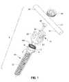
- FIG. 1illustrates an exploded view of the screw assembly according to the embodiments herein;
- FIG. 2illustrates an exploded view of the screw assembly during a step in the manufacturing according to the embodiments herein;
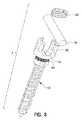
- FIG. 3illustrates an exploded view of the screw assembly during a step in the manufacturing according to the embodiments herein;
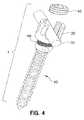
- FIG. 4illustrates an exploded view of the screw assembly during a step in the manufacturing according to the embodiments herein;
- FIG. 5illustrates a perspective view of the fully assembled screw assembly in a vertical position according to the embodiments herein;
- FIG. 6(A)illustrates an isolated perspective view of the screw head and bone screw interface according to a first embodiment herein;
- FIG. 6(B)illustrates an isolated perspective view of the screw head and bone screw interface according to a second embodiment herein;
- FIG. 6(C)illustrates an isolated perspective view of the screw head and bone screw interface according to a third embodiment herein;
- FIG. 6(D)illustrates an isolated perspective view of the screw head and bone screw interface according to a fourth embodiment herein;
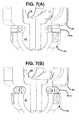
- FIG. 7(A)is a cross-sectional view of the screw head and bone screw interface of FIG. 6(A) according to the first embodiment herein;
- FIG. 7(B)is a cross-sectional view of the screw head and bone screw interface of FIG. 6(B) according to the second embodiment herein;
- FIG. 7(C)is a cross-sectional view of the screw head and bone screw interface of FIG. 6(C) according to the third embodiment herein;
- FIG. 7(D)is a cross-sectional view of the screw head and bone screw interface of FIG. 6(D) according to the fourth embodiment herein;
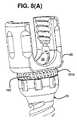
- FIG. 8(A)is an isolated perspective view of the screw head and bone screw interface of FIG. 6(B) with an interior rounded washer according to the second embodiment herein;
- FIG. 8(B)is a cross-sectional view of the screw head and bone screw interface of FIG. 8(A) with an interior rounded washer according to the second embodiment herein;
- FIGS. 9(A) through 9(H)are isolated views of the screw head according to the embodiments herein;
- FIG. 10(A)is a perspective view of a bone fixator assembly according to an alternate embodiment herein;
- FIG. 10(B)is a detailed view of the hook of the bone fixator assembly of FIG. 10(A) according to the alternate embodiment herein;
- FIGS. 11(A) through 11(B)are detailed views of the saddle pin according to the embodiments herein;
- FIGS. 12(A) through 12(B)are detailed views of alternate configurations of the saddle pin according to the embodiments herein;
- FIGS. 13 through 14are detailed views of still alternate configurations of the saddle pin according to the embodiments herein;
- FIGS. 15(A) through 15(C)are detailed views of the blocker according to the embodiments herein;
- FIG. 16is a flow diagram illustrating a preferred method according to the embodiments herein.
- FIGS. 1 through 16where similar reference characters denote corresponding features consistently throughout the figures, there are shown preferred embodiments.
- FIGS. 1 through 5provide an exploded view of the pedicle screw assembly 1 according to the embodiments herein.
- the screw assembly 1comprises a bone screw (fixator component) 10 having a threaded end 11 for engaging a bone (not shown) and a concave female socket end 12 for engaging and receiving the screw head 20 . Additionally, a load sharing mechanism 101 is included between the bone screw 10 and the screw head 20 .
- the embodiments hereinoffer excellent geometry to provide long lasting limited yet tensioned range of angulations of the screw head 20 relative to the bone screw 10 .
- the load sharing mechanism 101which may be embodied as a spring mechanism between the bone screw 10 and screw head 20 , one can achieve a dynamic stabilization assembly 1 using simple solid fatigue resistant longitudinal members 50 .
- the motionis limited by the space between the screw head 20 and the top (concave female socket end 12 ) of the bone screw 10 along with the load sharing mechanism 101 .
- the embodiments hereinoffer increased resistance, possibly acting as an artificial muscle.
- the assembly 1has many uses and may be used in various configurations of fixed, polyaxial, and dynamic screw systems including: a micro-motion fusion adjunct system that provides load sharing and helps avoid adjacent disc disease; a facet replacement system by providing torsional, axial, flexion, and extension ranges of motion; a load sharing and motion limiting system to complement a discectomy and postpone a fusion for several years; and a load sharing and motion limiting system to complement many of the conventional artificial discs currently being marketed and possibly being marketed in the future.
- a micro-motion fusion adjunct systemthat provides load sharing and helps avoid adjacent disc disease
- a facet replacement systemby providing torsional, axial, flexion, and extension ranges of motion
- a load sharing and motion limiting systemto complement a discectomy and postpone a fusion for several years
- a load sharing and motion limiting systemto complement many of the conventional artificial discs currently being marketed and possibly being marketed in the future.
- the load sharing mechanism 101is placed between the bone screw 10 and the screw head 20 and then the screw head 20 is first snapped into place in the bone screw 10 as shown in FIG. 2 . Then, as shown in FIG. 3 the saddle pin 30 snaps into place in the lower base portion 25 of the screw head 20 , which includes a groove 26 (best seen in FIG. 7 ) for receiving the saddle pin 30 .
- the screw assembly 1is prepared for ultra sonic cleaning to remove any impurities and subsequently may be shipped in this manufactured format (with the saddle pin 30 connected to the screw head 20 , which is connected to the bone screw 10 ).
- the female spherical pocket 12 of the bone screw 10has an undercut 7 to allow the screw head 20 to pivot freely but not to disassemble once the expanding saddle pin 30 is inserted.
- the thread 11 of the bone screw 10may be a multiple lead thread to allow faster insertion into a bone. This thread 11 may be tapered on the minor diameter while cylindrical on the major diameter to allow a new “bite” with every turn and to accommodate more thread depth towards the bottom of the bone screw 10 for the cancellous bone.
- FIG. 4illustrates the assembled view of the screw assembly 1 in the straight vertical direction.
- the threads 11 of the bone screw 10are double lead, which provides greater surface contact with the bone, but drives at 4 mm/revolution.
- the screw assembly 1can also be configured in a rotationally articulated position. The maximum angulation is 25 degrees/side, but the medial correction/travel of the longitudinal member 50 is 3.2 mm/side, which is nearly twice of what most conventional screws offer.
- FIGS. 6(A) and 7(A)illustrate an isolated view of the screw head and bone screw interface according to a first embodiment herein, wherein the load sharing mechanism 101 of FIGS. 1 through 5 is configured as a metallic wave/or hollowed washer 101 a that could allow some structural collapse.
- FIGS. 6(B) and 7(B)illustrate an isolated view of the screw head and bone screw interface according to a second embodiment herein, wherein the load sharing mechanism 101 of FIGS. 1 through 5 is configured as a metallic coil spring 101 b that is wrapped into a full diameter and may include an interior rounded washer 102 (as shown in FIGS. 8(A) and 8(B) ) to further limit the range of motion.
- FIGS. 6(C) and 7(C)illustrate an isolated view of the screw head and bone screw interface according to a third embodiment herein, wherein the load sharing mechanism 101 of FIGS. 1 through 5 is configured as a flexible polymer washer 101 c and may comprise silicon or urethane materials, for example.
- FIGS. 6(D) and 7(D)illustrate an isolated view of the screw head and bone screw interface according to a fourth embodiment herein, wherein the load sharing mechanism 101 of FIGS. 1 through 5 is configured as a metallic washer 101 d with strategically placed cutouts 105 that can allow some structural collapse in desired locations or directions.
- FIG. 9(A)illustrates the overall configuration of the screw head 20 .
- FIG. 9(B)illustrates a front view of the screw head 20 .
- FIG. 9(C)is a cross-sectional view from cut-line “CC” of FIG. 9(D) .
- FIG. 9(E)is a cross-sectional view from cut-line “BB” of FIG. 9(F) and
- FIG. 9(G)is a cross-sectional view from cut-line “AA” of FIG. 9(F) .
- FIG. 9(H)is an enlarged detailed view of the encircled area “A” of FIG. 9(G) illustrating the threaded inner portion 23 in more detail. As shown in FIGS.
- the screw head 20includes a bulbous (spherical) male end 21 for engaging the concave female socket 12 of the bone screw.
- the screw head 20also includes a pair of upright ends 22 opposite the bulbous male end 21 , wherein the upright ends 22 comprise a threaded inner portion 23 for engaging the blocker 40 .
- the screw head 20includes a generally open U-shaped inner portion 24 for receiving the saddle pin 30 and the longitudinal member 50 .
- the male end 21 of the screw head 20includes a plurality (for example, four or more) slots 6 that allow the male end 21 to expand into the female spherical pocket 12 of the bone screw 10 at any allowable angle once the saddle pin 30 is forced through.
- the screw head 20is pivoting inside the female socket end 12 of the bone screw 10 , the assembly 1 is allowed to be inserted deeper into the bone without having the bone or anatomy prematurely limit the range of angulations of the screw head 20 .
- the screw head 20further includes external features or cuts 29 that assist in accommodating surgical instrumentation during manipulation and assembly during the surgical procedure. These cuts 29 allow various instruments (not shown) to firmly and positively hold and manipulate the screw head 20 on one side or both sides of screw head 20 .
- FIG. 10(A)is a perspective view of a bone fixator assembly according to an alternate embodiment, wherein the bone fixator component is configured as a hook 60 .
- the hook 60is further illustrated in FIG. 10(B) .
- the hook 60includes a concave socket 12 having an inner portion 9 adapted to receive the bulbous end 21 of the screw head 20 ; and a dimpled outer portion 8 .
- the hook 60further includes a pair of arms 61 , 62 connected by a connection arm 64 .
- a space 63separates the arms 61 , 62 from one another.
- the arms 61 , 62are configured to receive an additional member (not shown) for subsequent attachment to the bone.
- the several embodiments of the saddle pin 30are shown in FIGS. 11(A) through 14 .
- the saddle pin 30provides a proper seat for the longitudinal member 50 and avoids notching a typical titanium longitudinal member 50 (titanium is very notch sensitive). Furthermore, the saddle pin 30 allows one to accommodate multiple sizes of longitudinal members 50 in the same screw assembly system 1 which is a first for a titanium system because of the above-mentioned notching factors.
- the saddle pin 30is configured with a slot 32 through the center to allow expansion of the upper portion (head) 131 of the saddle pin 30 .
- the bottom 35 of the saddle pin head 131is angled to accommodate the saddle pin 30 when spreading to accept a larger-sized longitudinal member 50 .
- the saddle pin 30initially expands the male sphere 21 of the screw head 20 into the female spherical socket 12 in the bone screw 10 causing the screw assembly system 1 to lock or start locking (i.e., causing the male sphere 21 of the screw head 20 to lock in the female spherical socket 12 of the bone screw 10 ).
- the saddle pin 30then “digs” into the female spherical socket 12 of the bone screw 10 to provide a secondary locking force to avoid bending failure of the assembly 1 .
- FIGS. 11(A) through 11(B)illustrate a first embodiment of the saddle pin 30 .
- the saddle pin 30generally includes an upper portion 131 and a lower portion 132 .
- the upper portionincludes as slot 32 , which is configured from the lowest area 33 of the upper portion 131 into the upper area 34 of the lower portion 132 of the saddle pin 30 .
- a secondary locking mechanism 36may be configured on the lower portion 132 of the saddle pin to further achieve locking of the saddle pin 30 once it is inserted in the screw head 20 .
- the lower portion 132 of the saddle pin 30terminates with a pointed end 37 to allow for digging into the female socket 12 of the bone screw 10 .
- FIGS. 12(A) through 12(B)illustrate a second embodiment of the saddle pin 30 .
- the difference between the first and second embodiments of the saddle pin 30is that the upper portion of the saddle pin 131 in the second embodiment includes two generally flat upper opposed ends 38 to more matingly configure with the geometry of the screw head 20 and the longitudinal member 50 .
- FIGS. 13 through 14illustrate a third embodiment of the saddle pin 30 .
- the saddle pin 30comprises two parts: an upper portion 131 preferably comprising titanium and a lower portion 132 which is preferably ceramic.
- the material of the lower portion 132 of the saddle pin 30is preferably ceramic and has a higher hardness and compressive yield strength than the comparative hardness and compressive yield strength of Ti 6 Al 4 V, which is the material which may be used in constructing the screw head 20 and bone screw 10 .
- the upper portion 131 of the saddle pin 30includes a slot 32 in the seat portion 133 and tapered angled ends 134 .
- the saddle pin 30i.e., the upper portion 131 and the ceramic tip 132 are assembled last in the overall process. Specifically, the screw head 20 snaps into the bone screw 10 . Then, the ceramic tip 132 slides into the screw head 20 , and finally the titanium saddle (upper portion) 131 is press fitted into the screw head 20 keeping everything in place and oriented in a relaxed state.
- the lower portion 132 of the saddle pinterminates with a series of cascading walls 137 , 138 having sloped angles, terminating with the pointed end 37 for attachment into the screw head 20 /bone screw 10 assembly.
- the material properties of the saddle pin tip 134are such that it prevents the deformation on the saddle pin 30 before the saddle pin 30 gives the proper bending and penetrating effects onto the screw head 20 /bone screw 10 assembly. Examples of the types of materials used for the saddle pin pointed end 37 include ZyranoxTM and HIP VitoxTM, both of which are available from Morgan Advanced Ceramics, United Kingdom.
- the blocker 40which is further illustrated in FIGS. 15(A) through 15(C) , includes a standard buttress thread 41 configured along an outer perimeter of the blocker 40 .
- the blocker 40helps to secure the longitudinal member 50 inside the screw head 40 .
- the threads 41 of the blocker 40are configured to engage the threads 23 of the screw head 20 . Additionally, the blocker 40 aids in preventing the expansion of the screw head 20 when torqued on the longitudinal member 50 , directing the counterforce more vertically than horizontally.
- the top 42 of the blocker 40has a fastening feature 43 such as a hex or square lock feature to allow high torque to be applied in locking the assembly 1 .
- the blocker 40may be configured with a free rotating saddle (not shown) to accommodate, via tangential contact, the longitudinal member 50 and help to further prevent notching of the titanium alloy used to construct the longitudinal member 50 .
- the blocker 40may have a “timed” thread 41 that is consistently and precisely related to the blocker driving tool (not shown) to help calculate the torsional and vertical position of the blocker 40 thereby assisting the torque measurement applied to the blocker 40 .
- FIG. 8illustrates a method of assembling a pedicle screw assembly 1 , wherein the method comprises positioning ( 200 ) a load sharing mechanism 101 , 101 a , 101 b , 101 c , 101 d in between a screw head 20 and a bone fixator component 10 ; attaching ( 210 ) the screw head 20 to the bone fixator component 10 such that the load sharing mechanism 101 , 101 a , 101 b , 101 c , 101 d provides tensile resistance to said screw head 20 ; securing ( 220 ) the bone fixator component 10 in the bone (not shown); securing ( 230 ) a saddle pin 30 in the screw head 20 ; engaging ( 240 ) the saddle pin 30 with the bone fixator component 10 ; inserting ( 250 ) a longitudinal member 50 in the screw head 20 ; and inserting ( 200 ) a load sharing mechanism 101 , 101 a , 101 b , 101 c , 101 d in between a screw head 20 and a bone
- the embodiments hereinprovide an axial movement of the screw head up to 25 degrees in any plane. Moreover, the embodiments herein allow for greater medial translation of the longitudinal member 50 (nearly 4 mm compared to the conventional devices which are generally limited to 2 mm).
- the assembly 1can be used as a dynamic rod system to complement artificial discs.
- the outside of the spherical joint part 21 of the screw head 20 and the inner spherical surface of the bone screw cup 12are coated with a wear resistant ceramic coating.
- the saddle pin 30is not digging into the bone screw 10 and in fact is configured at a shorter length than some of the other embodiments.
- This systemallows some motion instead of rigid fixation and shares the load with the artificial disc disallowing excessive forces being applied to the artificial disc and increasing its functional life. For example, this occurs as a result of the ceramic coating, which may be used in the embodiments herein.
- the spherical joint 21 of the screw head 20 and the inner spherical surface 12 of the bone screw 10have lower friction and higher wear resistance characteristics, thus improving the overall characteristics of the screw assembly 1 .
- the embodiments hereinprovide an assembly 1 comprising a screw head 20 comprising a bulbous end 21 ; a fixator component 10 configured for receiving the bulbous end 21 of the screw head 20 ; a pin 30 mounted in the screw head 20 ; and a blocker 40 adapted to engage the screw head 20 .
- the screw head 20comprises a slot 24 configured for receiving a longitudinal member 50 .
- the fixator component 10comprises a concave socket 12 configured for receiving the bulbous end 21 of the screw head 20 .
- the fixator component 10also comprises a threaded end 11 opposite the concave socket 12 and configured for attaching to a bone.
- the pin 30engages the fixator component 10 and a bottom portion 51 of the longitudinal member 50 .
- the blocker 40secures a top portion 52 of the longitudinal member 50 .
- the pin 30comprises an upper saddle portion 131 and a lower tip portion 132 .
- the pin 30may comprise a multi-part assembly.
- the upper saddle portion 131 of the pin 30comprises titanium and the lower tip portion 132 of the pin 30 comprises a ceramic material.
- the lower tip portion 132comprises a mechanically harder material than the upper saddle portion 131 .
- the screw head 20 and the fixator component 10comprise a first material, and the lower tip portion 132 of the pin 30 comprises a material having a higher material hardness and compressive yield strength than the first material.
- the assembly 1further comprises a wear resistant ceramic coating (not shown) over the screw head 20 and the fixator component 10 .
- the screw head 20further comprises two opposed upright ends 22 separated by the slot 24 , wherein each of the opposed upright ends 22 comprise an inner wall 27 and an outer wall 28 , wherein the inner wall 27 comprises wall threads 23 , and wherein the outer wall 28 comprises grooves (cuts) 29 .
- the blocker 40comprises blocker threads 41 configured around an outer perimeter 42 of the blocker 40 , the blocker threads 41 being dimensioned and configured to mate with the wall threads 23 .
- the upper saddle portion 131 of the pin 30comprises a slot 32 .
- the bulbous end 21 of the screw head 20comprises a plurality of slots 6 terminating at an opening 4 at a tip 3 of the bulbous end 21 .
- the bulbous end 21 of the screw head 20comprises a gap 19 configured to receive the pin 30 .
- the concave socket 12 of the fixator component 10comprises an inner portion 9 adapted to receive the bulbous end 21 of the screw head 20 ; and a dimpled outer portion 8 .
- the fixator component 10is configured as any of a threaded bone screw 10 (as shown in FIGS. 1 through 8 ) and a hook 60 (as shown in FIGS. 10(A) and 10(B) ) according to the several embodiments herein.
- the embodiments hereinprovide a pedicle screw assembly implant device 1 that has a load sharing mechanism 101 adapted to allow the screw head 20 to have an increased tensile load, and such that the assembly 1 may be used anteriorly or posteriorly, and which is capable of being utilized in surgeries to achieve anterior lumbar interbody fusion, posterior lumbar interbody fusion, transverse lumbar interbody fusion, correct degenerative disc disease, adult and pediatric scoliosis as a fixation device, and posterior cervical fusion.
- the embodiments hereinalso offer the surgeon more lateral range of motion than conventional products by utilizing the space under the screw head to provide a bigger arc of rotation.
- the saddle pin 30 componentoffers the flexibility to use a diametrical range of spinal longitudinal members 50 instead of a fixed size longitudinal member.
Landscapes
- Health & Medical Sciences (AREA)
- Orthopedic Medicine & Surgery (AREA)
- Life Sciences & Earth Sciences (AREA)
- Neurology (AREA)
- Surgery (AREA)
- Heart & Thoracic Surgery (AREA)
- Engineering & Computer Science (AREA)
- Biomedical Technology (AREA)
- Nuclear Medicine, Radiotherapy & Molecular Imaging (AREA)
- Medical Informatics (AREA)
- Molecular Biology (AREA)
- Animal Behavior & Ethology (AREA)
- General Health & Medical Sciences (AREA)
- Public Health (AREA)
- Veterinary Medicine (AREA)
- Surgical Instruments (AREA)
Abstract
Description
Claims (19)
Priority Applications (1)
| Application Number | Priority Date | Filing Date | Title |
|---|---|---|---|
| US13/005,227US8439954B2 (en) | 2004-02-27 | 2011-01-12 | Spring-loaded, load sharing polyaxial pedicle screw assembly and method |
Applications Claiming Priority (5)
| Application Number | Priority Date | Filing Date | Title |
|---|---|---|---|
| US54854304P | 2004-02-27 | 2004-02-27 | |
| US56565804P | 2004-04-27 | 2004-04-27 | |
| US11/045,908US7862594B2 (en) | 2004-02-27 | 2005-01-28 | Polyaxial pedicle screw assembly |
| US11/608,857US7892257B2 (en) | 2004-02-27 | 2006-12-11 | Spring loaded, load sharing polyaxial pedicle screw assembly and method |
| US13/005,227US8439954B2 (en) | 2004-02-27 | 2011-01-12 | Spring-loaded, load sharing polyaxial pedicle screw assembly and method |
Related Parent Applications (1)
| Application Number | Title | Priority Date | Filing Date |
|---|---|---|---|
| US11/608,857DivisionUS7892257B2 (en) | 2004-02-27 | 2006-12-11 | Spring loaded, load sharing polyaxial pedicle screw assembly and method |
Publications (2)
| Publication Number | Publication Date |
|---|---|
| US20110112582A1 US20110112582A1 (en) | 2011-05-12 |
| US8439954B2true US8439954B2 (en) | 2013-05-14 |
Family
ID=39512354
Family Applications (2)
| Application Number | Title | Priority Date | Filing Date |
|---|---|---|---|
| US11/608,857Expired - Fee RelatedUS7892257B2 (en) | 2004-02-27 | 2006-12-11 | Spring loaded, load sharing polyaxial pedicle screw assembly and method |
| US13/005,227Expired - Fee RelatedUS8439954B2 (en) | 2004-02-27 | 2011-01-12 | Spring-loaded, load sharing polyaxial pedicle screw assembly and method |
Family Applications Before (1)
| Application Number | Title | Priority Date | Filing Date |
|---|---|---|---|
| US11/608,857Expired - Fee RelatedUS7892257B2 (en) | 2004-02-27 | 2006-12-11 | Spring loaded, load sharing polyaxial pedicle screw assembly and method |
Country Status (3)
| Country | Link |
|---|---|
| US (2) | US7892257B2 (en) |
| EP (1) | EP2088946A4 (en) |
| WO (1) | WO2008073544A2 (en) |
Families Citing this family (61)
| Publication number | Priority date | Publication date | Assignee | Title |
|---|---|---|---|---|
| US7377923B2 (en) | 2003-05-22 | 2008-05-27 | Alphatec Spine, Inc. | Variable angle spinal screw assembly |
| US7604655B2 (en) | 2004-10-25 | 2009-10-20 | X-Spine Systems, Inc. | Bone fixation system and method for using the same |
| WO2006047711A2 (en) | 2004-10-25 | 2006-05-04 | Alphaspine, Inc. | Pedicle screw systems and methods |
| US7717943B2 (en) | 2005-07-29 | 2010-05-18 | X-Spine Systems, Inc. | Capless multiaxial screw and spinal fixation assembly and method |
| WO2007041702A2 (en) | 2005-10-04 | 2007-04-12 | Alphaspine, Inc. | Pedicle screw system with provisional locking aspects |
| US8097025B2 (en) | 2005-10-25 | 2012-01-17 | X-Spine Systems, Inc. | Pedicle screw system configured to receive a straight or curved rod |
| IL179135A (en)* | 2005-11-10 | 2010-11-30 | Elbit Systems Electro Optics Elop Ltd | Head up display mechanism |
| US7833252B2 (en) | 2006-01-27 | 2010-11-16 | Warsaw Orthopedic, Inc. | Pivoting joints for spinal implants including designed resistance to motion and methods of use |
| US8057519B2 (en)* | 2006-01-27 | 2011-11-15 | Warsaw Orthopedic, Inc. | Multi-axial screw assembly |
| US7722652B2 (en) | 2006-01-27 | 2010-05-25 | Warsaw Orthopedic, Inc. | Pivoting joints for spinal implants including designed resistance to motion and methods of use |
| US8740947B2 (en)* | 2006-02-15 | 2014-06-03 | Warsaw, Orthopedic, Inc. | Multiple lead bone fixation apparatus |
| US7776070B2 (en)* | 2006-08-02 | 2010-08-17 | Warsaw Orthopedic, Inc. | Occipital plating systems and methods |
| US9173722B2 (en)* | 2006-10-02 | 2015-11-03 | Cendres + Metaux Sa | Anchor for securing a tooth replacement |
| US8162990B2 (en)* | 2006-11-16 | 2012-04-24 | Spine Wave, Inc. | Multi-axial spinal fixation system |
| US10758283B2 (en) | 2016-08-11 | 2020-09-01 | Mighty Oak Medical, Inc. | Fixation devices having fenestrations and methods for using the same |
| WO2009011845A1 (en)* | 2007-07-13 | 2009-01-22 | George Frey | Systems and methods for spinal stabilization |
| US20110319943A1 (en) | 2007-08-20 | 2011-12-29 | Ryan Donahoe | Surgical Fixation System and Related Methods |
| US20090105756A1 (en) | 2007-10-23 | 2009-04-23 | Marc Richelsoph | Spinal implant |
| US8202300B2 (en)* | 2007-12-10 | 2012-06-19 | Custom Spine, Inc. | Spinal flexion and extension motion damper |
| US7967848B2 (en)* | 2008-01-16 | 2011-06-28 | Custom Spine, Inc. | Spring-loaded dynamic pedicle screw assembly |
| US8257401B2 (en)* | 2008-02-12 | 2012-09-04 | Spinal U.S.A. | Bottom mounted pedical screw assembly |
| US8491639B2 (en) | 2008-08-06 | 2013-07-23 | Spine Wave, Inc. | Multi-axial spinal fixation system |
| US9603629B2 (en) | 2008-09-09 | 2017-03-28 | Intelligent Implant Systems Llc | Polyaxial screw assembly |
| EP2328496A4 (en)* | 2008-09-26 | 2013-07-03 | Spartek Medical Inc | Load-sharing bone anchor, dynamic vertical rod and assemblies for dynamic stabilization of the spine |
| US8328856B1 (en) | 2008-10-14 | 2012-12-11 | Nuvasive, Inc. | Surgical fixation system and related methods |
| US8292934B2 (en)* | 2008-10-17 | 2012-10-23 | Warsaw Orthopedic, Inc. | Dynamic anchor assembly for connecting elements in spinal surgical procedures |
| US8075603B2 (en)* | 2008-11-14 | 2011-12-13 | Ortho Innovations, Llc | Locking polyaxial ball and socket fastener |
| US20100174322A1 (en)* | 2009-01-03 | 2010-07-08 | Custom Spine, Inc. | Biased Bumper Mechanism and Method |
| US8083780B2 (en)* | 2009-04-23 | 2011-12-27 | Custom Spine, Inc. | Spinal fixation mechanism |
| EP2421454A4 (en)* | 2009-04-23 | 2013-12-11 | Spinal Elements Inc | Transverse connectors |
| US20100291507A1 (en)* | 2009-05-13 | 2010-11-18 | Custom Spine, Inc. | Polyaxial Dental Implant |
| US20100305613A1 (en)* | 2009-05-29 | 2010-12-02 | Custom Spine, Inc. | Headless Polyaxial Screw System |
| EP2737865B1 (en)* | 2010-01-08 | 2016-04-20 | Biedermann Technologies GmbH & Co. KG | Bone screw |
| US8617216B2 (en)* | 2010-04-05 | 2013-12-31 | David L. Brumfield | Fully-adjustable bone fixation device |
| US20110257687A1 (en)* | 2010-04-19 | 2011-10-20 | Warsaw Orthopedic, Inc. | Load sharing bone fastener and methods of use |
| US10603083B1 (en) | 2010-07-09 | 2020-03-31 | Theken Spine, Llc | Apparatus and method for limiting a range of angular positions of a screw |
| US9084634B1 (en) | 2010-07-09 | 2015-07-21 | Theken Spine, Llc | Uniplanar screw |
| EP2462888B1 (en)* | 2010-12-10 | 2015-02-18 | Biedermann Technologies GmbH & Co. KG | Receiving part for receiving a rod for coupling the rod to a bone anchoring element and bone anchoring device with such a receiving part |
| US20120203281A1 (en)* | 2011-02-05 | 2012-08-09 | Alphatec Spine, Inc | Semi-rigid screw assembly |
| US9186184B2 (en) | 2011-02-14 | 2015-11-17 | Pioneer Surgical Technology, Inc. | Spinal fixation system and method |
| KR101093513B1 (en) | 2011-02-23 | 2011-12-14 | 이춘성 | Spinal Screw |
| FR2978343B1 (en)* | 2011-07-25 | 2013-08-23 | Medicrea International | ANCHORING BODY FOR VERTEBRAL OSTEOSYNTHESIS EQUIPMENT |
| US10022171B2 (en) | 2011-07-26 | 2018-07-17 | Scott & White Healthcare | Bone screws and bone screw systems |
| US8641736B2 (en)* | 2012-01-20 | 2014-02-04 | Warsaw Orthopedic, Inc. | Vertebral fastener system |
| US9247974B2 (en)* | 2012-07-06 | 2016-02-02 | Clariance | Polyaxial screw with mechanical thread and its friction device |
| DE102012016294B4 (en)* | 2012-08-16 | 2014-02-27 | Spontech Spine Intelligence Group Ag | Polyaxial connector for spinal fixation systems and spine fixation system |
| US8998968B1 (en) | 2012-11-28 | 2015-04-07 | Choice Spine, Lp | Facet screw system |
| US20140277163A1 (en)* | 2013-03-15 | 2014-09-18 | Ryan Kretzer | Reinforcement systems for spine stabilization constructs |
| US9968460B2 (en) | 2013-03-15 | 2018-05-15 | Medsmart Innovation Inc. | Dynamic spinal segment replacement |
| WO2014176507A1 (en)* | 2013-04-25 | 2014-10-30 | The University Of Toledo | Stabilized spinal fixation device |
| US9044273B2 (en) | 2013-10-07 | 2015-06-02 | Intelligent Implant Systems, Llc | Polyaxial plate rod system and surgical procedure |
| US9987047B2 (en)* | 2013-10-07 | 2018-06-05 | Spine Wave, Inc. | Translating polyaxial screw |
| US9579123B2 (en)* | 2014-09-19 | 2017-02-28 | Globus Medical, Inc. | Orthopedic stabilization devices and methods for installation thereof |
| FR3035318B1 (en) | 2015-04-24 | 2017-05-19 | Medicrea Int | MATERIAL OF VERTEBRAL OSTEOSYNTHESIS |
| IL244461A (en)* | 2016-03-06 | 2017-06-29 | Jacobsen Hagay | Adaptor for adjustably mounting a structure onto a biological base |
| US10743890B2 (en) | 2016-08-11 | 2020-08-18 | Mighty Oak Medical, Inc. | Drill apparatus and surgical fixation devices and methods for using the same |
| US12016573B2 (en) | 2016-08-11 | 2024-06-25 | Mighty Oak Medical, Inc. | Drill apparatus and surgical fixation devices and methods for using the same |
| WO2018039485A1 (en) | 2016-08-24 | 2018-03-01 | Integrity Implants, Inc. | Adjustable bone fixation systems |
| US10507043B1 (en) | 2017-10-11 | 2019-12-17 | Seaspine Orthopedics Corporation | Collet for a polyaxial screw assembly |
| CN108980181A (en)* | 2018-10-02 | 2018-12-11 | 湖州杭佳弹簧有限公司 | Connector with fine adjustment function |
| US11331123B2 (en)* | 2018-11-28 | 2022-05-17 | Warsaw Orthopedic, Inc. | Spinal implant |
Citations (70)
| Publication number | Priority date | Publication date | Assignee | Title |
|---|---|---|---|---|
| US3054321A (en) | 1959-07-15 | 1962-09-18 | Macchia Anthony | Screw assembly with ball and socket connection |
| US4887596A (en) | 1988-03-02 | 1989-12-19 | Synthes (U.S.A.) | Open backed pedicle screw |
| US4946458A (en) | 1986-04-25 | 1990-08-07 | Harms Juergen | Pedicle screw |
| US5067955A (en) | 1989-04-13 | 1991-11-26 | Societe De Fabrication De Material Orthopedique | Vertebral implant for osteosynthesis device |
| US5129388A (en) | 1989-02-09 | 1992-07-14 | Vignaud Jean Louis | Device for supporting the spinal column |
| US5246442A (en) | 1991-12-31 | 1993-09-21 | Danek Medical, Inc. | Spinal hook |
| US5360431A (en) | 1990-04-26 | 1994-11-01 | Cross Medical Products | Transpedicular screw system and method of use |
| US5443467A (en) | 1993-03-10 | 1995-08-22 | Biedermann Motech Gmbh | Bone screw |
| US5466237A (en) | 1993-11-19 | 1995-11-14 | Cross Medical Products, Inc. | Variable locking stabilizer anchor seat and screw |
| US5476464A (en) | 1993-02-25 | 1995-12-19 | Howmedica Gmbh | Device for setting a spine |
| US5520689A (en) | 1992-06-04 | 1996-05-28 | Synthes (U.S.A.) | Osteosynthetic fastening device |
| US5536268A (en) | 1992-12-23 | 1996-07-16 | Plus Endoprothetik Ag | System for osteosynthesis at the vertebral column, connecting element for such a system and tool for its placement and removal |
| US5545165A (en) | 1992-10-09 | 1996-08-13 | Biedermann Motech Gmbh | Anchoring member |
| US5669911A (en) | 1995-04-13 | 1997-09-23 | Fastenetix, L.L.C. | Polyaxial pedicle screw |
| US5672176A (en) | 1995-03-15 | 1997-09-30 | Biedermann; Lutz | Anchoring member |
| US5733286A (en) | 1997-02-12 | 1998-03-31 | Third Millennium Engineering, Llc | Rod securing polyaxial locking screw and coupling element assembly |
| US5735851A (en) | 1996-10-09 | 1998-04-07 | Third Millennium Engineering, Llc | Modular polyaxial locking pedicle screw |
| US5752957A (en)* | 1997-02-12 | 1998-05-19 | Third Millennium Engineering, Llc | Polyaxial mechanism for use with orthopaedic implant devices |
| WO1998034554A1 (en) | 1997-02-11 | 1998-08-13 | Sdgi Holdings, Inc. | Multi-axial bone screw assembly |
| US5863293A (en) | 1996-10-18 | 1999-01-26 | Spinal Innovations | Spinal implant fixation assembly |
| US5879350A (en) | 1996-09-24 | 1999-03-09 | Sdgi Holdings, Inc. | Multi-axial bone screw assembly |
| US5882350A (en) | 1995-04-13 | 1999-03-16 | Fastenetix, Llc | Polyaxial pedicle screw having a threaded and tapered compression locking mechanism |
| US5951553A (en) | 1997-07-14 | 1999-09-14 | Sdgi Holdings, Inc. | Methods and apparatus for fusionless treatment of spinal deformities |
| US5964767A (en) | 1997-09-12 | 1999-10-12 | Tapia; Eduardo Armando | Hollow sealable device for temporary or permanent surgical placement through a bone to provide a passageway into a cavity or internal anatomic site in a mammal |
| US5964760A (en) | 1996-10-18 | 1999-10-12 | Spinal Innovations | Spinal implant fixation assembly |
| WO1999055246A1 (en) | 1998-04-29 | 1999-11-04 | Dimso (Distribution Medicale Du Sud-Ouest) | Backbone osteosynthesis system for anterior fixing |
| US5989250A (en) | 1996-10-24 | 1999-11-23 | Spinal Concepts, Inc. | Method and apparatus for spinal fixation |
| US6022350A (en) | 1996-05-13 | 2000-02-08 | Stryker France S.A. | Bone fixing device, in particular for fixing to the sacrum during osteosynthesis of the backbone |
| US6030389A (en) | 1997-08-04 | 2000-02-29 | Spinal Concepts, Inc. | System and method for stabilizing the human spine with a bone plate |
| US6045579A (en) | 1997-05-01 | 2000-04-04 | Spinal Concepts, Inc. | Adjustable height fusion device |
| US6063090A (en) | 1996-12-12 | 2000-05-16 | Synthes (U.S.A.) | Device for connecting a longitudinal support to a pedicle screw |
| US6074391A (en) | 1997-06-16 | 2000-06-13 | Howmedica Gmbh | Receiving part for a retaining component of a vertebral column implant |
| US6077262A (en) | 1993-06-04 | 2000-06-20 | Synthes (U.S.A.) | Posterior spinal implant |
| US6090111A (en) | 1998-06-17 | 2000-07-18 | Surgical Dynamics, Inc. | Device for securing spinal rods |
| US6090110A (en) | 1992-03-02 | 2000-07-18 | Howmedica Gmbh | Apparatus for bracing vertebrae |
| US6113601A (en) | 1998-06-12 | 2000-09-05 | Bones Consulting, Llc | Polyaxial pedicle screw having a loosely coupled locking cap |
| US6132430A (en) | 1996-10-24 | 2000-10-17 | Spinal Concepts, Inc. | Spinal fixation system |
| US6187005B1 (en) | 1998-09-11 | 2001-02-13 | Synthes (Usa) | Variable angle spinal fixation system |
| WO2001022893A1 (en) | 1999-09-27 | 2001-04-05 | Blackstone Medical, Inc. | A surgical screw system and related methods |
| EP1090595A2 (en) | 1999-10-07 | 2001-04-11 | Stryker Spine SA | Slotted head pedicle screw assembly |
| DE19950075A1 (en) | 1999-10-18 | 2001-04-19 | Robert Bongartz | Implant holder at a spinal column has a screw driven into the vertebra with a head to take a hollow ball for a link with a free movement to position the angle of the implant |
| US6248105B1 (en) | 1997-05-17 | 2001-06-19 | Synthes (U.S.A.) | Device for connecting a longitudinal support with a pedicle screw |
| US6273888B1 (en) | 1999-05-28 | 2001-08-14 | Sdgi Holdings, Inc. | Device and method for selectively preventing the locking of a shape-memory alloy coupling system |
| US6280442B1 (en) | 1999-09-01 | 2001-08-28 | Sdgi Holdings, Inc. | Multi-axial bone screw assembly |
| US6302888B1 (en) | 1999-03-19 | 2001-10-16 | Interpore Cross International | Locking dovetail and self-limiting set screw assembly for a spinal stabilization member |
| US20020010467A1 (en) | 2000-07-22 | 2002-01-24 | Corin Spinal Systems Limited | Pedicle attachment assembly |
| US6368321B1 (en) | 2000-12-04 | 2002-04-09 | Roger P. Jackson | Lockable swivel head bone screw |
| US6371957B1 (en) | 1997-01-22 | 2002-04-16 | Synthes (Usa) | Device for connecting a longitudinal bar to a pedicle screw |
| US6454769B2 (en) | 1997-08-04 | 2002-09-24 | Spinal Concepts, Inc. | System and method for stabilizing the human spine with a bone plate |
| US6475218B2 (en) | 2000-06-30 | 2002-11-05 | Sofamor, S.N.C. | Spinal implant for an osteosynthesis device |
| EP1254640A2 (en) | 2001-05-02 | 2002-11-06 | Biomet Merck Limited | Swivel coupling |
| US6485491B1 (en) | 2000-09-15 | 2002-11-26 | Sdgi Holdings, Inc. | Posterior fixation system |
| US6485492B1 (en) | 1998-08-08 | 2002-11-26 | Bernd Schafer | Osteosynthesis device |
| US6488681B2 (en) | 2001-01-05 | 2002-12-03 | Stryker Spine S.A. | Pedicle screw assembly |
| EP1293168A2 (en) | 2001-09-14 | 2003-03-19 | Stryker Spine | Biased angulation bone fixation assembly |
| US20030073996A1 (en) | 2001-10-17 | 2003-04-17 | Doubler Robert L. | Split ring bone screw for a spinal fixation system |
| US6565565B1 (en) | 1998-06-17 | 2003-05-20 | Howmedica Osteonics Corp. | Device for securing spinal rods |
| WO2003068088A1 (en) | 2002-02-13 | 2003-08-21 | Cross Medical Products, Inc. | Posterior polyaxial system for the spine |
| US6610063B2 (en) | 2000-07-28 | 2003-08-26 | Synthes (Usa) | Spinal fixation system |
| US20030163133A1 (en) | 2002-02-13 | 2003-08-28 | Moti Altarac | Posterior rod system |
| US20030199873A1 (en) | 2002-04-18 | 2003-10-23 | Marc Richelsoph | Screw and rod fixation assembly and device |
| US6641586B2 (en) | 2002-02-01 | 2003-11-04 | Depuy Acromed, Inc. | Closure system for spinal fixation instrumentation |
| US6648888B1 (en) | 2002-09-06 | 2003-11-18 | Endius Incorporated | Surgical instrument for moving a vertebra |
| US6736820B2 (en) | 2000-11-10 | 2004-05-18 | Biedermann Motech Gmbh | Bone screw |
| US6780186B2 (en) | 1995-04-13 | 2004-08-24 | Third Millennium Engineering Llc | Anterior cervical plate having polyaxial locking screws and sliding coupling elements |
| US6890334B2 (en) | 2000-04-19 | 2005-05-10 | Synthes (U.S.A.) | Bone fixation assembly |
| US6896677B1 (en) | 2003-12-11 | 2005-05-24 | A-Spine Holding Group Corp. | Rotary device for retrieving spinal column under treatment |
| US20050113927A1 (en) | 2003-11-25 | 2005-05-26 | Malek Michel H. | Spinal stabilization systems |
| US20060241599A1 (en) | 2003-06-27 | 2006-10-26 | Konieczynski David D | Polyaxial Bone Screw |
| US7524326B2 (en) | 2003-09-12 | 2009-04-28 | Signus Medizintechnik Gmbh | Bone screw |
Family Cites Families (1)
| Publication number | Priority date | Publication date | Assignee | Title |
|---|---|---|---|---|
| US7862594B2 (en)* | 2004-02-27 | 2011-01-04 | Custom Spine, Inc. | Polyaxial pedicle screw assembly |
- 2006
- 2006-12-11USUS11/608,857patent/US7892257B2/ennot_activeExpired - Fee Related
- 2007
- 2007-09-05WOPCT/US2007/077564patent/WO2008073544A2/enactiveApplication Filing
- 2007-09-05EPEP07841834Apatent/EP2088946A4/ennot_activeWithdrawn
- 2011
- 2011-01-12USUS13/005,227patent/US8439954B2/ennot_activeExpired - Fee Related
Patent Citations (93)
| Publication number | Priority date | Publication date | Assignee | Title |
|---|---|---|---|---|
| US3054321A (en) | 1959-07-15 | 1962-09-18 | Macchia Anthony | Screw assembly with ball and socket connection |
| US4946458A (en) | 1986-04-25 | 1990-08-07 | Harms Juergen | Pedicle screw |
| US4887596A (en) | 1988-03-02 | 1989-12-19 | Synthes (U.S.A.) | Open backed pedicle screw |
| US5129388A (en) | 1989-02-09 | 1992-07-14 | Vignaud Jean Louis | Device for supporting the spinal column |
| US5067955A (en) | 1989-04-13 | 1991-11-26 | Societe De Fabrication De Material Orthopedique | Vertebral implant for osteosynthesis device |
| US5360431A (en) | 1990-04-26 | 1994-11-01 | Cross Medical Products | Transpedicular screw system and method of use |
| US5474555A (en) | 1990-04-26 | 1995-12-12 | Cross Medical Products | Spinal implant system |
| US5246442A (en) | 1991-12-31 | 1993-09-21 | Danek Medical, Inc. | Spinal hook |
| US6090110A (en) | 1992-03-02 | 2000-07-18 | Howmedica Gmbh | Apparatus for bracing vertebrae |
| US7128743B2 (en) | 1992-03-02 | 2006-10-31 | Stryker Trauma Gmbh | Apparatus for bracing vertebrae |
| US5520689A (en) | 1992-06-04 | 1996-05-28 | Synthes (U.S.A.) | Osteosynthetic fastening device |
| US5545165A (en) | 1992-10-09 | 1996-08-13 | Biedermann Motech Gmbh | Anchoring member |
| US5536268A (en) | 1992-12-23 | 1996-07-16 | Plus Endoprothetik Ag | System for osteosynthesis at the vertebral column, connecting element for such a system and tool for its placement and removal |
| US5476464A (en) | 1993-02-25 | 1995-12-19 | Howmedica Gmbh | Device for setting a spine |
| US5443467A (en) | 1993-03-10 | 1995-08-22 | Biedermann Motech Gmbh | Bone screw |
| US6077262A (en) | 1993-06-04 | 2000-06-20 | Synthes (U.S.A.) | Posterior spinal implant |
| US5466237A (en) | 1993-11-19 | 1995-11-14 | Cross Medical Products, Inc. | Variable locking stabilizer anchor seat and screw |
| US5672176A (en) | 1995-03-15 | 1997-09-30 | Biedermann; Lutz | Anchoring member |
| USRE39089E1 (en) | 1995-04-13 | 2006-05-02 | Fastenetix, Llc | Polyaxial pedicle screw having a threaded and tapered compression locking mechanism |
| USRE37665E1 (en) | 1995-04-13 | 2002-04-16 | Fastenetix, Llc | Polyaxial pedicle screw having a threaded and tapered compression locking mechanism |
| US5882350A (en) | 1995-04-13 | 1999-03-16 | Fastenetix, Llc | Polyaxial pedicle screw having a threaded and tapered compression locking mechanism |
| US6780186B2 (en) | 1995-04-13 | 2004-08-24 | Third Millennium Engineering Llc | Anterior cervical plate having polyaxial locking screws and sliding coupling elements |
| US5669911A (en) | 1995-04-13 | 1997-09-23 | Fastenetix, L.L.C. | Polyaxial pedicle screw |
| US6022350A (en) | 1996-05-13 | 2000-02-08 | Stryker France S.A. | Bone fixing device, in particular for fixing to the sacrum during osteosynthesis of the backbone |
| US6290703B1 (en) | 1996-05-13 | 2001-09-18 | Stryker France S.A. | Device for fixing the sacral bone to adjacent vertebrae during osteosynthesis of the backbone |
| US5879350A (en) | 1996-09-24 | 1999-03-09 | Sdgi Holdings, Inc. | Multi-axial bone screw assembly |
| US5885286A (en) | 1996-09-24 | 1999-03-23 | Sdgi Holdings, Inc. | Multi-axial bone screw assembly |
| US6053917A (en) | 1996-09-24 | 2000-04-25 | Sdgi Holdings, Inc. | Multi-axial bone screw assembly |
| US5735851A (en) | 1996-10-09 | 1998-04-07 | Third Millennium Engineering, Llc | Modular polyaxial locking pedicle screw |
| US6132432A (en) | 1996-10-18 | 2000-10-17 | Spinal Innovations Llc | Spinal implant fixation assembly |
| US5863293A (en) | 1996-10-18 | 1999-01-26 | Spinal Innovations | Spinal implant fixation assembly |
| US5964760A (en) | 1996-10-18 | 1999-10-12 | Spinal Innovations | Spinal implant fixation assembly |
| US6132430A (en) | 1996-10-24 | 2000-10-17 | Spinal Concepts, Inc. | Spinal fixation system |
| US6562040B1 (en) | 1996-10-24 | 2003-05-13 | Spinal Concepts, Inc. | Spinal fixation system |
| US5989250A (en) | 1996-10-24 | 1999-11-23 | Spinal Concepts, Inc. | Method and apparatus for spinal fixation |
| US6595992B1 (en) | 1996-10-24 | 2003-07-22 | Spinal Concepts, Inc. | Method and apparatus for spinal fixation |
| US6416515B1 (en) | 1996-10-24 | 2002-07-09 | Spinal Concepts, Inc. | Spinal fixation system |
| US6613050B1 (en) | 1996-10-24 | 2003-09-02 | Spinal Concepts, Inc. | Method and apparatus for spinal fixation |
| US6063090A (en) | 1996-12-12 | 2000-05-16 | Synthes (U.S.A.) | Device for connecting a longitudinal support to a pedicle screw |
| US7022122B2 (en) | 1997-01-22 | 2006-04-04 | Synthes (U.S.A.) | Device for connecting a longitudinal bar to a pedicle screw |
| US6371957B1 (en) | 1997-01-22 | 2002-04-16 | Synthes (Usa) | Device for connecting a longitudinal bar to a pedicle screw |
| WO1998034554A1 (en) | 1997-02-11 | 1998-08-13 | Sdgi Holdings, Inc. | Multi-axial bone screw assembly |
| US5733286A (en) | 1997-02-12 | 1998-03-31 | Third Millennium Engineering, Llc | Rod securing polyaxial locking screw and coupling element assembly |
| US5752957A (en)* | 1997-02-12 | 1998-05-19 | Third Millennium Engineering, Llc | Polyaxial mechanism for use with orthopaedic implant devices |
| US6045579A (en) | 1997-05-01 | 2000-04-04 | Spinal Concepts, Inc. | Adjustable height fusion device |
| US6248105B1 (en) | 1997-05-17 | 2001-06-19 | Synthes (U.S.A.) | Device for connecting a longitudinal support with a pedicle screw |
| US6074391A (en) | 1997-06-16 | 2000-06-13 | Howmedica Gmbh | Receiving part for a retaining component of a vertebral column implant |
| US5951553A (en) | 1997-07-14 | 1999-09-14 | Sdgi Holdings, Inc. | Methods and apparatus for fusionless treatment of spinal deformities |
| US6030389A (en) | 1997-08-04 | 2000-02-29 | Spinal Concepts, Inc. | System and method for stabilizing the human spine with a bone plate |
| US6454769B2 (en) | 1997-08-04 | 2002-09-24 | Spinal Concepts, Inc. | System and method for stabilizing the human spine with a bone plate |
| US5964767A (en) | 1997-09-12 | 1999-10-12 | Tapia; Eduardo Armando | Hollow sealable device for temporary or permanent surgical placement through a bone to provide a passageway into a cavity or internal anatomic site in a mammal |
| WO1999055246A1 (en) | 1998-04-29 | 1999-11-04 | Dimso (Distribution Medicale Du Sud-Ouest) | Backbone osteosynthesis system for anterior fixing |
| US6881215B2 (en) | 1998-04-29 | 2005-04-19 | Stryker Spine | Backbone osteosynthesis system with clamping means in particular for anterior fixing |
| US6113601A (en) | 1998-06-12 | 2000-09-05 | Bones Consulting, Llc | Polyaxial pedicle screw having a loosely coupled locking cap |
| US6090111A (en) | 1998-06-17 | 2000-07-18 | Surgical Dynamics, Inc. | Device for securing spinal rods |
| US6565565B1 (en) | 1998-06-17 | 2003-05-20 | Howmedica Osteonics Corp. | Device for securing spinal rods |
| US6485492B1 (en) | 1998-08-08 | 2002-11-26 | Bernd Schafer | Osteosynthesis device |
| US6187005B1 (en) | 1998-09-11 | 2001-02-13 | Synthes (Usa) | Variable angle spinal fixation system |
| US6302888B1 (en) | 1999-03-19 | 2001-10-16 | Interpore Cross International | Locking dovetail and self-limiting set screw assembly for a spinal stabilization member |
| US6273888B1 (en) | 1999-05-28 | 2001-08-14 | Sdgi Holdings, Inc. | Device and method for selectively preventing the locking of a shape-memory alloy coupling system |
| US6280442B1 (en) | 1999-09-01 | 2001-08-28 | Sdgi Holdings, Inc. | Multi-axial bone screw assembly |
| US6660004B2 (en) | 1999-09-01 | 2003-12-09 | Sdgi Holdings, Inc. | Multi-axial bone screw assembly |
| WO2001022893A1 (en) | 1999-09-27 | 2001-04-05 | Blackstone Medical, Inc. | A surgical screw system and related methods |
| US6554834B1 (en) | 1999-10-07 | 2003-04-29 | Stryker Spine | Slotted head pedicle screw assembly |
| EP1090595A2 (en) | 1999-10-07 | 2001-04-11 | Stryker Spine SA | Slotted head pedicle screw assembly |
| DE19950075A1 (en) | 1999-10-18 | 2001-04-19 | Robert Bongartz | Implant holder at a spinal column has a screw driven into the vertebra with a head to take a hollow ball for a link with a free movement to position the angle of the implant |
| US6890334B2 (en) | 2000-04-19 | 2005-05-10 | Synthes (U.S.A.) | Bone fixation assembly |
| US6475218B2 (en) | 2000-06-30 | 2002-11-05 | Sofamor, S.N.C. | Spinal implant for an osteosynthesis device |
| US20020010467A1 (en) | 2000-07-22 | 2002-01-24 | Corin Spinal Systems Limited | Pedicle attachment assembly |
| US6626908B2 (en) | 2000-07-22 | 2003-09-30 | Corin Spinal Systems Limited | Pedicle attachment assembly |
| US7118571B2 (en) | 2000-07-28 | 2006-10-10 | Synthes (U.S.A.) | Spinal fixation system |
| US6610063B2 (en) | 2000-07-28 | 2003-08-26 | Synthes (Usa) | Spinal fixation system |
| US6485491B1 (en) | 2000-09-15 | 2002-11-26 | Sdgi Holdings, Inc. | Posterior fixation system |
| US20040153077A1 (en) | 2000-11-10 | 2004-08-05 | Lutz Biedermann | Bone screw |
| US6736820B2 (en) | 2000-11-10 | 2004-05-18 | Biedermann Motech Gmbh | Bone screw |
| US6368321B1 (en) | 2000-12-04 | 2002-04-09 | Roger P. Jackson | Lockable swivel head bone screw |
| US6858030B2 (en) | 2001-01-05 | 2005-02-22 | Stryker Spine | Pedicle screw assembly and methods therefor |
| US6488681B2 (en) | 2001-01-05 | 2002-12-03 | Stryker Spine S.A. | Pedicle screw assembly |
| EP1254640A2 (en) | 2001-05-02 | 2002-11-06 | Biomet Merck Limited | Swivel coupling |
| US20030055426A1 (en) | 2001-09-14 | 2003-03-20 | John Carbone | Biased angulation bone fixation assembly |
| US6974460B2 (en) | 2001-09-14 | 2005-12-13 | Stryker Spine | Biased angulation bone fixation assembly |
| EP1293168A2 (en) | 2001-09-14 | 2003-03-19 | Stryker Spine | Biased angulation bone fixation assembly |
| US6623485B2 (en) | 2001-10-17 | 2003-09-23 | Hammill Manufacturing Company | Split ring bone screw for a spinal fixation system |
| US20030073996A1 (en) | 2001-10-17 | 2003-04-17 | Doubler Robert L. | Split ring bone screw for a spinal fixation system |
| US6641586B2 (en) | 2002-02-01 | 2003-11-04 | Depuy Acromed, Inc. | Closure system for spinal fixation instrumentation |
| US20030163133A1 (en) | 2002-02-13 | 2003-08-28 | Moti Altarac | Posterior rod system |
| WO2003068088A1 (en) | 2002-02-13 | 2003-08-21 | Cross Medical Products, Inc. | Posterior polyaxial system for the spine |
| US20030199873A1 (en) | 2002-04-18 | 2003-10-23 | Marc Richelsoph | Screw and rod fixation assembly and device |
| US6648888B1 (en) | 2002-09-06 | 2003-11-18 | Endius Incorporated | Surgical instrument for moving a vertebra |
| US20060241599A1 (en) | 2003-06-27 | 2006-10-26 | Konieczynski David D | Polyaxial Bone Screw |
| US7524326B2 (en) | 2003-09-12 | 2009-04-28 | Signus Medizintechnik Gmbh | Bone screw |
| US20050113927A1 (en) | 2003-11-25 | 2005-05-26 | Malek Michel H. | Spinal stabilization systems |
| US6896677B1 (en) | 2003-12-11 | 2005-05-24 | A-Spine Holding Group Corp. | Rotary device for retrieving spinal column under treatment |
Also Published As
| Publication number | Publication date |
|---|---|
| WO2008073544A2 (en) | 2008-06-19 |
| US7892257B2 (en) | 2011-02-22 |
| US20110112582A1 (en) | 2011-05-12 |
| US20070093832A1 (en) | 2007-04-26 |
| EP2088946A2 (en) | 2009-08-19 |
| EP2088946A4 (en) | 2012-07-18 |
| WO2008073544A3 (en) | 2008-10-02 |
Similar Documents
| Publication | Publication Date | Title |
|---|---|---|
| US8439954B2 (en) | Spring-loaded, load sharing polyaxial pedicle screw assembly and method | |
| EP1725175B1 (en) | Polyaxial pedicle screw assembly | |
| EP1722700B1 (en) | Biased angle polyaxial pedicle screw assembly | |
| US7819902B2 (en) | Medialised rod pedicle screw assembly | |
| US7967848B2 (en) | Spring-loaded dynamic pedicle screw assembly | |
| JP4594509B2 (en) | Stem screw assembly | |
| US20050277928A1 (en) | Spinal implant fixation assembly | |
| US20080065075A1 (en) | METHOD FOR SPINE STABILIZATION DURING OSTEOSYNTHESIS (As Amended) | |
| US20080086131A1 (en) | Bone screw fixation | |
| US20060052783A1 (en) | Polyaxial device for spine stabilization during osteosynthesis | |
| WO2007038076A1 (en) | Spinal implant with variable link mechanism | |
| JP2009511171A (en) | Multi-directional moving device for fixing the spine during osteosynthesis surgery | |
| JP2023514243A (en) | Integrated multi-point fixing screw | |
| US20110046684A1 (en) | Screw Assembly and Method | |
| US20100305615A1 (en) | Multi-level Polyaxial Screw Connection Mechanism |
Legal Events
| Date | Code | Title | Description |
|---|---|---|---|
| AS | Assignment | Owner name:CUSTOM SPINE, INC., NEW JERSEY Free format text:ASSIGNMENT OF ASSIGNORS INTEREST;ASSIGNOR:ABDELGANY, MAHMOUD F.;REEL/FRAME:025625/0929 Effective date:20110111 | |
| STCF | Information on status: patent grant | Free format text:PATENTED CASE | |
| AS | Assignment | Owner name:EXWORKS ASSET HOLDINGS, LLC, ILLINOIS Free format text:ASSIGNMENT OF ASSIGNORS INTEREST;ASSIGNOR:CUSTOM SPINE, INC.;REEL/FRAME:036208/0526 Effective date:20150717 | |
| AS | Assignment | Owner name:CUSTOM SPINE ACQUISITION, INC., GEORGIA Free format text:ASSIGNMENT OF ASSIGNORS INTEREST;ASSIGNOR:EXWORKS ASSET HOLDINGS LLC;REEL/FRAME:037915/0959 Effective date:20160114 | |
| AS | Assignment | Owner name:ANTARES CAPITAL LP, AS AGENT, ILLINOIS Free format text:SECURITY INTEREST;ASSIGNOR:CUSTOM SPINE ACQUISITION, INC.;REEL/FRAME:038581/0722 Effective date:20160429 | |
| AS | Assignment | Owner name:CORTLAND CAPITAL MARKET SERVICES LLC, AS AGENT, IL Free format text:SECURITY INTEREST;ASSIGNOR:CUSTOM SPINE ACQUISITION, INC.;REEL/FRAME:038608/0230 Effective date:20160429 | |
| FPAY | Fee payment | Year of fee payment:4 | |
| FEPP | Fee payment procedure | Free format text:MAINTENANCE FEE REMINDER MAILED (ORIGINAL EVENT CODE: REM.); ENTITY STATUS OF PATENT OWNER: SMALL ENTITY | |
| FEPP | Fee payment procedure | Free format text:7.5 YR SURCHARGE - LATE PMT W/IN 6 MO, SMALL ENTITY (ORIGINAL EVENT CODE: M2555); ENTITY STATUS OF PATENT OWNER: SMALL ENTITY | |
| MAFP | Maintenance fee payment | Free format text:PAYMENT OF MAINTENANCE FEE, 8TH YR, SMALL ENTITY (ORIGINAL EVENT CODE: M2552); ENTITY STATUS OF PATENT OWNER: SMALL ENTITY Year of fee payment:8 | |
| AS | Assignment | Owner name:PERCEPTIVE CREDIT HOLDINGS IV, LP, NEW YORK Free format text:SECURITY INTEREST;ASSIGNORS:SPINAL ELEMENTS, INC.;CUSTOM SPINE ACQUISITION, INC.;OMNI ACQUISITION INC.;REEL/FRAME:067596/0295 Effective date:20240531 | |
| AS | Assignment | Owner name:CUSTOM SPINE ACQUISITION, INC., CALIFORNIA Free format text:RELEASE BY SECURED PARTY;ASSIGNOR:CORTLAND CAPITAL MARKET SERVICES LLC, AS AGENT;REEL/FRAME:067605/0717 Effective date:20240531 Owner name:CUSTOM SPINE ACQUISITION, INC., CALIFORNIA Free format text:RELEASE BY SECURED PARTY;ASSIGNOR:ANTARES CAPITAL LP, AS ADMINISTRATIVE AGENT;REEL/FRAME:067605/0646 Effective date:20240531 | |
| FEPP | Fee payment procedure | Free format text:MAINTENANCE FEE REMINDER MAILED (ORIGINAL EVENT CODE: REM.); ENTITY STATUS OF PATENT OWNER: SMALL ENTITY | |
| LAPS | Lapse for failure to pay maintenance fees | Free format text:PATENT EXPIRED FOR FAILURE TO PAY MAINTENANCE FEES (ORIGINAL EVENT CODE: EXP.); ENTITY STATUS OF PATENT OWNER: SMALL ENTITY | |
| STCH | Information on status: patent discontinuation | Free format text:PATENT EXPIRED DUE TO NONPAYMENT OF MAINTENANCE FEES UNDER 37 CFR 1.362 | |
| FP | Lapsed due to failure to pay maintenance fee | Effective date:20250514 |