US8439953B2 - Spinal stabilization system and method - Google Patents
Spinal stabilization system and methodDownload PDFInfo
- Publication number
- US8439953B2 US8439953B2US11/779,762US77976207AUS8439953B2US 8439953 B2US8439953 B2US 8439953B2US 77976207 AUS77976207 AUS 77976207AUS 8439953 B2US8439953 B2US 8439953B2
- Authority
- US
- United States
- Prior art keywords
- structural member
- vertebra
- spinous process
- structural
- connector
- Prior art date
- Legal status (The legal status is an assumption and is not a legal conclusion. Google has not performed a legal analysis and makes no representation as to the accuracy of the status listed.)
- Expired - Lifetime, expires
Links
Images


Classifications
- A—HUMAN NECESSITIES
- A61—MEDICAL OR VETERINARY SCIENCE; HYGIENE
- A61B—DIAGNOSIS; SURGERY; IDENTIFICATION
- A61B17/00—Surgical instruments, devices or methods
- A61B17/16—Instruments for performing osteoclasis; Drills or chisels for bones; Trepans
- A61B17/1604—Chisels; Rongeurs; Punches; Stamps
- A61B17/1606—Chisels; Rongeurs; Punches; Stamps of forceps type, i.e. having two jaw elements moving relative to each other
- A—HUMAN NECESSITIES
- A61—MEDICAL OR VETERINARY SCIENCE; HYGIENE
- A61B—DIAGNOSIS; SURGERY; IDENTIFICATION
- A61B17/00—Surgical instruments, devices or methods
- A61B17/16—Instruments for performing osteoclasis; Drills or chisels for bones; Trepans
- A61B17/1662—Instruments for performing osteoclasis; Drills or chisels for bones; Trepans for particular parts of the body
- A61B17/1671—Instruments for performing osteoclasis; Drills or chisels for bones; Trepans for particular parts of the body for the spine
- A—HUMAN NECESSITIES
- A61—MEDICAL OR VETERINARY SCIENCE; HYGIENE
- A61B—DIAGNOSIS; SURGERY; IDENTIFICATION
- A61B17/00—Surgical instruments, devices or methods
- A61B17/56—Surgical instruments or methods for treatment of bones or joints; Devices specially adapted therefor
- A61B17/58—Surgical instruments or methods for treatment of bones or joints; Devices specially adapted therefor for osteosynthesis, e.g. bone plates, screws or setting implements
- A61B17/68—Internal fixation devices, including fasteners and spinal fixators, even if a part thereof projects from the skin
- A61B17/70—Spinal positioners or stabilisers, e.g. stabilisers comprising fluid filler in an implant
- A61B17/7062—Devices acting on, attached to, or simulating the effect of, vertebral processes, vertebral facets or ribs ; Tools for such devices
- A61B17/7067—Devices bearing against one or more spinous processes and also attached to another part of the spine; Tools therefor
- A—HUMAN NECESSITIES
- A61—MEDICAL OR VETERINARY SCIENCE; HYGIENE
- A61B—DIAGNOSIS; SURGERY; IDENTIFICATION
- A61B17/00—Surgical instruments, devices or methods
- A61B17/56—Surgical instruments or methods for treatment of bones or joints; Devices specially adapted therefor
- A61B17/58—Surgical instruments or methods for treatment of bones or joints; Devices specially adapted therefor for osteosynthesis, e.g. bone plates, screws or setting implements
- A61B17/68—Internal fixation devices, including fasteners and spinal fixators, even if a part thereof projects from the skin
- A61B17/70—Spinal positioners or stabilisers, e.g. stabilisers comprising fluid filler in an implant
- A61B17/7062—Devices acting on, attached to, or simulating the effect of, vertebral processes, vertebral facets or ribs ; Tools for such devices
- A61B17/7068—Devices comprising separate rigid parts, assembled in situ, to bear on each side of spinous processes; Tools therefor
- A—HUMAN NECESSITIES
- A61—MEDICAL OR VETERINARY SCIENCE; HYGIENE
- A61B—DIAGNOSIS; SURGERY; IDENTIFICATION
- A61B17/00—Surgical instruments, devices or methods
- A61B17/16—Instruments for performing osteoclasis; Drills or chisels for bones; Trepans
- A61B17/1604—Chisels; Rongeurs; Punches; Stamps
- A—HUMAN NECESSITIES
- A61—MEDICAL OR VETERINARY SCIENCE; HYGIENE
- A61B—DIAGNOSIS; SURGERY; IDENTIFICATION
- A61B17/00—Surgical instruments, devices or methods
- A61B17/56—Surgical instruments or methods for treatment of bones or joints; Devices specially adapted therefor
- A61B2017/564—Methods for bone or joint treatment
Definitions
- the present inventiongenerally relates to the field of medical devices, and more particularly to a system for stabilizing a portion of a spinal column.
- the systemjoins together adjacent spinous processes to stabilize a portion of a spine.
- Spinal instabilitymay result from many factors including trauma or degenerative disorders stemming from injuries and/or aging. In some instances, the effects of spinal instability may result in pain and/or partial or complete loss of mobility.
- interbody devicesmay be implanted within a prepared disc space to replace all or a portion of a damaged or compressed disc.
- vertebrae adjacent to a damaged or defective discmay be fused to each other with an interbody device or with interbody devices.
- interbody devicesalone may not be capable of supporting a portion of a spine sufficiently to promote vertebral fusion.
- a separate stabilization systemmay be required to improve stability of the spine or a portion of the spine.
- a pedicle screw systemmay stabilize one vertebra by connecting the vertebra to a second vertebra using anchoring pedicle screws and/or connecting rods or, plates.
- the connecting rods or platesmay extend between the vertebrae.
- Pedicle screwsare generally installed in pairs for each vertebral level that requires fixation.
- a pedicle screwis typically inserted into a pre-bored hole at the junction of a superior articular process and transverse process through the pedicle.
- a pedicle screwmay be inserted in a craniolateral to caudomedial direction, depending on the particular region of the spine being stabilized.
- Pedicle screw insertionis a technically demanding surgical procedure for spinal stabilization due to the close proximity of the spinal cord canal and/or major blood vessels. Complications may occur during the installation or use of pedicle screws for spinal stabilization or immobilization. Complications may include neural or dural damage as a result of pedicle screw penetration into the spinal canal or intervertebral foramen, pedicle screw bending and/or pedicle screw breakage. In addition, pedicle screw insertion may require highly invasive surgery. Such surgery may result in extended recovery times or even irreparable damage to adjacent tissues. Pedicle screws may be angulated in a craniolateral to caudomedial direction, depending on placement within the spine. Angulation of the pedicle screws may require a large exposure of the spine during insertion to accommodate desired trajectories of the pedicle screws.
- the bracesmay provide flexion/extension immobilization of the vertebrae.
- the bracesmay include plate systems positioned adjacent to the spine.
- plate systemsare comprised of two opposing plates positioned on opposite sides of vertebral spinous processes. The plates may vary in size to accommodate variations in spinal anatomy.
- spinal plate systemsmay utilize nut and bolt assemblies positioned in pre-drilled holes in the plates.
- the boltsare positioned in the space between the spinous processes of adjacent vertebrae. These systems may depend on a compressive force applied to the lateral sides of the spinous processes by the opposing plates to hold the system to the vertebrae.
- U.S. Pat. No. 5,527,312 issued to Raywhich is incorporated by reference as if fully set forth herein, describes a system incorporating a facet screw anchor and fixation bar for immobilizing two vertebrae relative to each other.
- a portion of a fixation baris wrapped around a portion of a superior vertebra pedicle.
- the fixation baris secured to a facet screw anchor and the facet screw anchor is positioned through a facet joint of the superior vertebra and into the base of a transverse process of an inferior vertebra.
- the fixation bar and facet screwimmobilize the superior vertebra and the inferior vertebra.
- a spinal stabilization systemmay be used to increase stability of a portion of a spine.
- the spinal stabilization systemmay require a minimally intrusive surgical installation procedure.
- the spinal stabilization systemmay provide flexion/extension, torsion, and lateral bending stability to at least a portion of a spine.
- the systemmay be used as a stand-alone system or used in combination with other systems or devices.
- a spinal stabilization systemmay include structural members positioned on opposite sides of a spinous process.
- a structural membermay extend from a first vertebra to a second vertebra.
- the structural membersmay include openings on opposite sides of spinous processes of the vertebrae.
- the structural membersmay include texturing that allows a portion of the structural members to penetrate into spinous processes when the structural members are coupled to the spinous processes during an insertion procedure.
- the texturingcomprises spikes.
- Connectorsmay be positioned through openings in the structural members to couple the structural members to the spinous processes and to each other. The connectors provide a point of stabilization for the spinal stabilization system.
- structural membersmay include flanges having flange openings. Fasteners may be positioned through the flange openings. The fasteners may be positioned through facet joints of vertebrae being stabilized. A fastener on each side of a spinous process may provide two points of fixation for each vertebra. Structural members with flanges may be provided in mirror image pairs to fit on opposite sides of spinous processes.
- a connectormay couple a structural member to an adjacent structural member.
- a connectormay couple multiple structural members to a portion of a vertebra or vertebrae.
- a portion of a connectormay pass through an opening in a structural member and through an opening in a spinous process of a vertebra.
- the connectormay be positioned through a structural member and/or vertebral opening at an oblique angle relative to a centerline axis of the opening.
- a portion of a connectormay abut an opening surface to inhibit continued axial movement of the connector through the opening during use.
- a punch tool and a connector toolmay be used during an installation process. The punch tool may form an opening through a spinous process.
- a connectormay be positioned through the opening to couple structural members positioned on opposite sides of spinous processes together.
- a connector toolmay form a connector that joins the structural members together.
- the spinal stabilization systemmay include a pair of structural members positioned adjacent to opposing sides of a spinous process of a first vertebra. Openings may extend through the structural members to allow access to vertebral surfaces of the first vertebra from an outer surface of a structural member. Texture on a surface of a structural member may abut vertebral surfaces to provide a frictional and/or form coupling between the structural member and the vertebra. In some embodiments, portions of the texturing may penetrate into vertebral bone during installation.
- Ends of a structural membermay be placed adjacent to spinous processes of vertebrae to be stabilized. Openings in the structural member may abut openings through spinous processes. Connectors may be formed in openings to join together structural members positioned on opposite sides of the spinous processes.
- a spinal stabilization systemmay be adapted to stabilize a portion of a spine where a spinous process is not present, has been damaged or removed, or is not capable of withstanding structural loads for spinal fixation.
- a spinal stabilization systemmay provide or restore stability to the lumbosacral region of the spine.
- An artificial spinous processmay be inserted to function as a spinous process for the stabilization system.
- a spinal stabilization systemmay couple a first vertebra to an adjacent second vertebra (one vertebral level).
- the second vertebramay be coupled to an adjacent third vertebra.
- the spatial and angular relationship between the first and second vertebrae and the second and third vertebraemay be different.
- a spinal stabilization systemmay maintain the natural spatial and angular relationship between the adjacent vertebral levels.
- the spinal stabilization systemmay establish a desired spatial and angular relationship between adjacent vertebrae.
- a spinal stabilization systemmay accommodate means for promoting bone growth between adjacent vertebrae.
- Bone graftmay be placed adjacent to a structural member of a spinal stabilization system and the spinous processes of adjacent vertebrae coupled to the structural member to promote fusion between the vertebrae. Additionally, bone graft may be placed between an articular facet joint of adjacent vertebrae after removing the necessary soft tissue or exposing the inter-articular space.
- a fastenermay be positioned through portions of the adjacent vertebrae and the facet joint to immobilize the joint and promote bone growth
- a spinal fixation systemmay be used to substantially increase the stability of a portion of a spine containing an interbody fusion device and also relieve a significant amount of pressure on the interbody device.
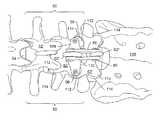
- FIG. 1depicts a posterior view of a portion of a spine with an embodiment of a spinal stabilization system for stabilizing a vertebral level.
- FIG. 2depicts an embodiment of a first member of a connector.
- FIG. 3depicts an embodiment of a second member of a connector.
- FIG. 4depicts an embodiment of an assembled connector.
- FIG. 5depicts a perspective view of a spinal stabilization system.
- FIG. 6depicts a top view of a spinal stabilization system.
- FIG. 7depicts a perspective view of a spinal stabilization system.
- FIG. 8depicts a top view of a spinal stabilization system.
- FIG. 9depicts a posterior view of a portion of a spine with an embodiment of a spinal stabilization system for stabilizing a vertebral level.
- FIG. 10depicts a perspective view of an embodiment of a spinal stabilization system.
- FIG. 11depicts an embodiment of a structural member.
- FIG. 12depicts a perspective view of an embodiment of a structural member having an elongated opening.
- FIG. 13depicts a front view of an embodiment of a connector tool
- FIG. 14depicts a perspective view of an embodiment of a multi-level spinal stabilization system.
- FIG. 15depicts a perspective view of an embodiment of a spinal stabilization system having an interconnecting spacer.
- FIG. 16depicts a spinal stabilization system for use in stabilizing more than one vertebral level.
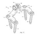
- FIG. 17depicts an embodiment of a spinal stabilization system used to stabilize a portion of the lumbosacral region of the spine.
- FIG. 18depicts an embodiment of a spinal stabilization system used to stabilize a portion of the lumbosacral region of the spine.
- FIG. 19depicts an embodiment of an artificial spinous process for use with a spinal stabilization system.
- FIG. 20depicts an embodiment of an artificial spinous process that strengthens or replaces a natural spinous process.
- FIG. 21depicts an embodiment of spinal stabilization system coupled to an artificial spinous process.
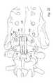
- FIG. 22depicts an embodiment of a spinal stabilization system attached to a human spine for fusing an L5 lumbar vertebra to a sacrum.
- FIG. 23depicts an embodiment of a spinal stabilization system coupled to artificial spinous members.
- FIG. 24depicts an embodiment of a spinal stabilization system with an artificial spinous member.
- FIG. 25depicts an embodiment of a spinal stabilization system with an artificial spinous member.
- FIG. 26depicts an embodiment of a punch tool that may be used to form an opening through a spinous process.
- FIG. 27depicts a detailed view of the hollow cutter used in the punch tool of FIG. 26 .
- a spinal stabilization systemmay provide stabilization for one or more vertebral levels of a spine.
- a spinal stabilization systemmay be utilized as a stand-alone system.
- a spinal stabilization systemmay be used in conjunction with other systems or devices to provide stability to the spine.
- a spinal stabilization systemmay be used in conjunction with a spinal implant (e.g., an interbody fusion device, an artificial disc, and/or a vertebral construct).
- the spinal stabilization systemmay be easy to install with only minimal intrusion to adjacent tissue and muscle as compared to conventional stabilization systems.
- the spinal stabilization systemmay provide minimal risk of dural or neural damage during installation and use.
- Appropriately sized spinal stabilization systemsmay be used to couple adjacent vertebrae of a spinal column.
- an appropriately sized spinal stabilization systemmay be used to join an L2 vertebra to an L1 vertebra, or an L1 vertebra to a T12 vertebra.
- FIG. 1depicts an embodiment of spinal stabilization system 48 .
- Spinal stabilizationmay be used to stabilize vertebral level 50 .
- Vertebral level 50may include two vertebrae 52 , and intervertebral disc 54 . Portions of vertebrae 52 may form bilateral facet joints 56 .
- spinal stabilization system 48may include structural members 58 and connectors 60 .
- Structural members 58may have a length that spans from spinous process 62 of a first vertebra to spinous process 62 of an adjacent vertebra that is to be fixed in position relative to the first vertebra.
- Structural members 58may have a rod form or a bar form, or may have any other form able to withstand tensile, compressive, and/or torsion loads associated with the spine.
- structural members 58may be coupled to each side of spinous processes 62 .
- spinal stabilization system 48may be coupled to spinous processes 62 of the L4 vertebra 52 ′ and the L5 vertebra 52 ′′.
- Connectors 60may couple the structural members 58 to spinous processes 62 .
- Connectors 60may be any type of connector that couples structural members 58 together.
- Structural members 58may be formed in various sizes. The various sizes may accommodate different sizes of patients. Various sizes may also accommodate different sizes needed to stabilize different vertebrae.
- An instrument set supplied to a surgeonmay include several different sizes of structural members.
- structural members to be positioned on a left side of a spinous processmay be substantially a mirror image of a structural member to be placed on a right side of a spinous process.
- An instrumentation setmay include several different sizes of structural member pairs.
- Structural members and connectorsmay be made of any biocompatible materials. Structural members and connectors may be formed of, but are not limited to being formed of, metals, ceramics, polymers, and/or composites. In some embodiments, structural members and connectors may be formed of titanium, titanium alloys, steel, and/or steel alloys. In some embodiments, structural members and/or connectors may be or may include bioabsorbable material.
- a shape of a structural membermay be adjusted prior to insertion into a patient to conform to the patient's anatomy.
- the structural membermay be capable of accommodating minor plastic deformation without altering the structural member's mechanical properties. Benders may be included in an instrumentation kit to allow structural members to be shaped.
- connectors 60may be formed of a first member and a second member
- FIG. 2depicts an embodiment of first member 66 .
- First member 66may include head 68 , shark 70 having grooves 72 on an inner surface, slot 74 , and tool opening 76 .
- Head 68may be larger than an opening in a structural member to inhibit passage of first member through the structural member.
- shank 70 of first member 66includes a plurality of grooves 72 to engage a second member and form an interference fit that inhibits separation of the first and second members.
- grooves 72are female thread in the inner surface of shank 70 .
- shank 70may include a single groove, a plurality of ridges, and/or a single ridge to couple the first member to a second member.
- First member 66may include slot 74 along a portion of a length of the first member. Slot 74 may allow first member 66 to radially expand during assembly of a connector.
- Tool opening 76may allow first member 66 to be coupled to a connector tool.
- First member 66may be placed on a first arm of the connector tool.
- a second membermay be placed on a second arm of the connector tool.
- the connector toolmay be activated to bring the arms together and form a connector from first member 66 and the second member.
- FIG. 3depicts an embodiment of second member 78 .
- Second member 78may include head 80 , shank 82 , and tool opening 84 .
- Head 80may be larger than an opening in a structural member to inhibit passage of second member through the structural member.
- Tool opening 84may allow second member 78 to be coupled to an arm of a connector tool.
- an outer surface of shank 82may include a surface that engages and locks with a shank of a first member.
- shank 82includes a plurality of ridges 86 to engage grooves in a shank of the first member.
- shank 82includes male threading that is configured to engage female threading in inner surface of the shank of the first member.
- shank 82may include a single groove, a plurality of grooves, and/or a single ridge to couple the second member to a first member.
- FIG. 4depicts connector 60 .
- Shank 82 of second member 78may be pressed into shank 70 of first member 66 so that ridges 86 of the second member engage grooves 72 in the first member. The orientation of the ridges and grooves may inhibit separation of first member 66 from second member 78 when the first member and second member are coupled together.
- connector 60is formed.
- Slot 74may allow first member 66 to radially expand when ridged shank 82 is inserted into the first member. Ridges of second member 78 may engage grooves of first member 66 to inhibit separation of connector 601 .
- a structural member of a spinal stabilization systemmay include openings that accept a head of either first member 66 or second member 78 .
- a punch toolmay be used to form an opening through a spinous process.
- Structural membersmay be placed on each side of the spinous process so that the openings of the structural members align with the opening through the spinous process.
- First member 66 and second member 78may be coupled to a connector tool.
- the connector toolmay be used to couple first member 66 to second member 78 in openings through the structural members and the opening through the spinous process to form connector 60 .
- FIG. 5depicts a perspective view of spinal stabilization system 48 .
- Connector 60may include threading on an inside surface of first member 66 to engage threading 88 of second member 78 .
- First member 66may include slot 74 that allows the first member to expand when second member 78 is inserted into the first member to couple the first member to the second member.
- Second member 78may be pressed into first member 66 using a connector tool. Threading of first member 66 and threading 88 of second member 78 may allow for removal of connector 60 from structural members 58 .
- Tool openingsmay include slots, hexagonal openings, or other types of openings for engaging a drive tool (e.g., a ratchet drive) that allows for separation of the first member from the second member.
- a drive toole.g., a ratchet drive
- Joining a connector together by pressing a second member into a first membermay allow for simple and efficient formation of a spinal fixation system.
- the ability to separate the first member from the second membermay allow for removal of a spinal fixation system or portions of the spinal fixation system should problems arise during an insertion procedure or at a later time.
- connectors 60may be positioned within openings 90 in structural members 58 .
- Connector 60may be placed through structural member openings 90 in a direction that is substantially parallel to central axes of the openings. Openings 90 may allow a first portion of a connector to pass through the opening while inhibiting a head of the connector from passing through the opening. Heads 68 , 80 of a first member and a second member may be too large to pass through structural member opening 90 .
- Connectorsmay be used to join together two or more structural members to form spinal stabilization system 48 .
- Heads 68 , 80may have shapes that correspond to surfaces defining structural member openings 90 .
- the shape of connector heads or fastener heads and the corresponding shapes of surfaces defined by openings in the structural membersmay allow connectors and/or fasteners to be positioned at desired angles relative to the structural members and vertebrae during an insertion procedure.
- the shape of openings 90 and the shape of heads 68 , 80may accommodate some misalignment between the openings of structural members 58 .
- structural members 58may include texturing 92 .
- Texturing 92may provide a secure connection between structural member 58 and a portion of a vertebra placed against the textured surface. The secure connection may inhibit movement of structural member 58 relative to the vertebra after the structural member and the vertebra are coupled together.
- Texturing 92may include protrusions or roughening.
- texturing 92 shown in FIG. 5 and FIG. 6includes spikes. Texturing may include, but is not limited to, spikes, teeth, scoring, sharp particles implanted into surfaces of the structural members, ridges and grooves, and/or serrations.
- Surfaces of structural members that contact bonemay include a coating of material to promote osseointegration of the structural member with bone. The coating may be, but is not limited to, a bone morphogenic protein, hydroxyapatite, and/or a titanium plasma spray.
- FIG. 6depicts implant 94 positioned between structural members 58 .
- Implant 94may be a portion of bone or other graft material for promoting fusion of the spinous processes that the structural members are coupled to.
- spinal stabilization systemsmay use fasteners to couple vertebrae together.
- an end of a spinal stabilization systemmay be coupled to vertebrae using fasteners, and a second end of the spinal stabilization system may be coupled to a spinous process of a vertebra using a connector.
- each end of a spinal stabilization systemmay be coupled to a spinous process using a connector, and fasteners may be positioned through facet joints of the vertebrae.
- Fastenersmay include, but are not limited to, screws, nails, rivets, trocars, pins, and barbs.
- the fastenersare bone screws.
- a length of a fastenermay allow the fastener to engage multiple vertebrae.
- a fastenermay include a head and a shaft extending from the head. A portion of a tool may be inserted into an indention in the fastener head to position and insert the fastener. The size of the fastener head may inhibit the fastener head from passing through a structural member opening.
- a portion of a fastener headmay substantially mate with a portion of an opening wall in a structural members. The mating surfaces may be textured to help keep the fastener angle fixed relative to the structural member.
- the shape of the fastener headmay allow the fastener to be inserted through the opening at an oblique angle and support loads to secure the fastener within the opening.
- a length of a fastener shaftmay allow the fastener to be positioned through a portion of a vertebra and into an adjacent vertebra.
- a fastener shaftmay have threading or a series of ridges and grooves to secure the fastener to a vertebra or vertebrae.
- surface roughnessmay be provided on a fastener shaft to secure the fastener to adjacent surfaces.
- Spinal stabilization system 48may include a fastener for coupling a portion of a first vertebra to a portion of a second vertebra and/or a portion of a vertebra to a structural member.
- Fasteners 96such as the fasteners shown in FIG. 7 and FIG. 8 , may include heads 98 and shanks 100 .
- An outer dimension of fastener head 98may be greater than an outer dimension of shanks 100 .
- Shanks 100may be sized to pass through openings in structural members. Heads 98 may be larger than openings to inhibit complete passage of a fastener through an opening in a structural member.
- Fastener head 98may include indention 102 for the insertion of a portion of a tool used to drive fastener 96 .
- Spinal stabilization system 48may include structural members 58 and 58 ′, connector 60 , and fasteners 96 .
- Structural members 58 and 58 ′may include openings for fasteners and/or connectors to engage vertebrae or other structural members.
- Fasteners 96 and/or connectors 60may be positioned through openings at angles oblique to a centerline axis of the openings.
- Structural members 58 and 58 ′may include texturing or protrusions on surfaces adjacent to vertebrae and/or adjacent to other structural members to provide form and/or friction coupling to the adjacent surfaces.
- a portion of structural member 58may be positioned adjacent the spinous process of a first vertebra and a second portion of structural member 58 may be positioned adjacent a spinous process of a second vertebra.
- Opposing structural member 58 ′may be positioned along the opposite side of the spinous processes of the first and second vertebrae.
- Fasteners 96may be positioned through an opening of structural member 58 , through a lamina of the first vertebra, and through an articular facet joint of the first and second vertebrae to couple structural member 58 to the vertebrae and fixate the articular facet joint between the first and second vertebrae.
- Fasteners 96may be positioned through an opening, through the opposite lamina of the first vertebra, and through a second articular facet joint of the first and second vertebrae.
- Connector 60may couple structural members 58 and 58 ′ to the spinous process of the second vertebra.
- structural members 58 and 58 ′may have differing lengths to allow fasteners 96 to engage the vertebrae.
- FIG. 9depicts an embodiment of a spinal stabilization system.
- Structural members 58may include flange 108 , elongated portion 110 , and openings for connectors 60 .
- a portion of flange 108may be positioned adjacent to an articular process and facet of a first vertebra during use.
- a portion of a bottom surface of a flangemay include texturing that couples the flange to a vertebral body. The texturing may include, but is not limited to, scoring, protrusions, spikes, serrations, and/or particles embedded in the surface.
- Elongated portion 110may have a length that spans from a spinous process of the first vertebra to a spinous process of an adjacent vertebra to be fixed in position relative to the first vertebra.
- Connectors 60 and fasteners 96may affix the structural members 58 to vertebrae.
- structural members 58attach to spinous process 62 ′, and to each inferior articular process 112 .
- spinal stabilization system 48attaches to spinous process 62 ′′, and to each superior articular process 114 .
- FIG. 10depicts a perspective view of an embodiment of spinal stabilization system 48 .
- FIG. 11depicts an embodiment of a structural member used to form spinal stabilization system 48 .
- Structural member 58may include texturing 92 adjacent to openings 90 . Texturing on a side of structural member 58 away from flange 108 may enter vertebral bone during installation to help secure the structural member to the vertebrae. Texturing 92 on a side of structural member towards flange 108 may allow a frictional or, interference fit to be formed between a first structural member and a second structural member that abuts the first structural member to form a multi-level construct (e.g., as shown in FIG. 14 ). Texturing may promote fixation of a desired angle between portions of a multilevel construct that stabilize different vertebral levels.
- a structural member of a multi-level constructmay span over vertebral level.
- a structural membermay be coupled to 3 or more spinous processes to stabilize a portion of the spine.
- a structural member for stabilizing two vertebral levelsmay include two openings proximate ends of the structural member, as well as an opening proximate a midpoint of the structural member. The openings may be positioned such that connectors and/or fasteners can be used to couple the structural member to the adjacent spinous processes.
- the structural membermay include texturing. Texturing may be used to engage a portion of a vertebra, an additional structural member, and/or an implant (e.g., bone graft).
- a structural membermay include spikes to engage a spinous process.
- a first portion of flange opening 115may overlap a second portion of the opening.
- the overlapping opening portionsmay provide options for placement of a fastener during an insertion procedure.
- flange opening 115may include only a single portion, two overlapping portions, or more than two overlapping portions.
- a flange openingmay include an elongated slot instead of overlapping portions. Openings 90 in structural member 58 for connectors in elongated portion may include overlapping portions or elongated slots that provide options for positional placement of the connectors.
- FIG. 13shows a front view of an embodiment of connector tool 116 for inserting a connector.
- Insertion instrument 116may include handles 118 ′, 118 ′′, linking mechanism 120 , arms 122 , spring 124 , ratchet arm 126 , and holders 128 .
- Linking mechanism 120may allow holders 128 that are attached to arms 122 to approach each other from an open position with a small, or ino, rotational component of motion when handles 118 are squeezed towards each other.
- a first member and a second member of a connectormay be placed on holders 128 .
- a shank of the second membermay be placed in a shank of the first member when handles 118 are squeezed together.
- Ratchet arm 126may be rotatively attached to first handle 118 ′.
- Teeth 130 of ratchet arm 126may engage an end of second handle 118 ′′. Teeth 130 may be oriented to allow handles 118 to approach each other when the handles are squeezed, but the teeth may inhibit the handles from returning to the open position. Spring 124 may apply force to handles 118 that forces the handles to the open position. When connector members are coupled together, ratchet arm 126 may be rotated away from the end of second handle 118 ′′ to allow spring 124 , and/or a controlled release of pressure applied to handles 118 , to return the insertion instrument to the open position.
- Tool openings 76 and 84 of connector members 66 , 78may be attached to holders 128 of insertion instrument 116 .
- Holders 128may include slots 132 , O-rings, or another type of mechanism that allows the connector members to be securely attached to the holders. Slots 132 of holders 128 may be compressed when connector members are attached to the holders. Force applied by expansion of holders 128 against connector members 66 , 78 may hold the connector members on the holders with enough force to inhibit unintentional removal of the connector members from the holders. After connector members 66 , 78 are joined together by squeezing handles 118 of insertion instrument 116 , holders 128 may be removed from tool openings 76 , 84 . The force applied by expansion of holders 128 against connector members 66 , 78 may be significantly less than a force that resists separation of joined connector members so that the holders may be easily removed from tool openings 76 and 84 of formed connector 60 .
- connectorsmay not be used to join structural members together.
- an adhesivemay be used to bind structural members to a spinous process or to spinous processes. Using an adhesive may avoid the need to form an opening through a spinous process or spinous processes.
- Structural member 58may include a flange and an elongated portion.
- the structural memberis made of a single piece of material.
- structural member 58is made of a number of separate pieces that are joined together.
- the flangemay be joined to the elongated portion by any method that provides a connection between the flange and the elongated portion that is able to withstand tensile, compressive, and/or torsion loads associated with the spine (e.g., by adhesion or by welding).
- the elongated portionsmay be formed from plate stock, bar stock, or rod stock. Flanges may be formed from plate stock.
- structural members 58may be cast, molded, or otherwise formed as a single piece.
- a fastenermay include a break-off extension.
- the break-off extensionmay couple to a tool.
- the break-off extensionmay separate from a remaining portion of the fastener when enough force has been applied to the fastener to insert the fastener in bone.
- Use of a break-off extensionmay inhibit over-tightening of fasteners that results in the stripping of threading in the bone.
- an expandable ringmay be inserted in a structural member. Rings may be compressed and inserted into openings in structural members. After insertion, the rings may expand. Expansion of the rings may allow the rings to be coupled to the structural members to inhibit removal of the rings from the openings without the rings becoming secured to the structural members.
- a shank of a fastenermay be inserted through a ring and into bone. A portion or portions of the ring may expand as a head of the fastener is inserted into the bone. After passage of a portion of the fastener into bone, a wide section of the head may pass beyond the portion or portions of the ring. Passage of the wide section of the head beyond the portion or portions may allow the portions or portions to contract. The portions may inhibit removal of the fastener from the structural member without fixedly binding the ring to the structural member and without fixedly binding the ring to the fastener.
- shank 100 of fastener 96may be threaded for securing the fastener to a portion of a vertebra or vertebrae.
- a fastenermay include texturing, or ridges and grooves, to provide friction and/or form coupling to secure a fastener to a portion of a vertebra. Threading of fastener 96 may be self-tapping to avoid the need for pre-boring and tapping of an opening in the vertebra. In some embodiments, holes may be bored and/or tapped in the vertebra to accommodate threading of fastener 96 .
- Shank 100 of fastener 96may be positioned through a structural member opening at an oblique angle relative to a centerline axis of the opening in the structural member.
- a portion of fastener head 98may be shaped to complement a portion of a flange opening.
- FIG. 10depicts shanks of fasteners inserted through flange openings in structural member 58 .
- a fastenermay pass through a facet joint formed by an inferior articular process of a first vertebra and an adjacent superior articular process of a second vertebra to provide a point of fixation between structural member 58 and the first and second vertebrae.
- FIG. 14depicts an embodiment of spinal stabilization system 48 for stabilizing more than one vertebral level.
- a multi-level stabilization systemmay include multiple structural members that join vertebral levels. Using a multi-level spinal stabilization system that includes multiple structural members may allow for preservation of the natural curvature of the spine.
- the structural membersmay be coupled to each vertebral level using fasteners and/or connectors.
- a structural membermay be coupled to another structural member using fasteners and/or connectors.
- Spinal stabilization system 48 for stabilizing multiple vertebral levelsmay include structural members 58 , connectors 60 , and fasteners 96 .
- Structural members 58 a and 58 a ′may be positioned on opposing sides of the spinous processes of a first vertebra and a second vertebra.
- Structural members 58 a and 58 a ′may be coupled to the first and second vertebrae using fasteners and connectors.
- Structural members 58 b and 58 b ′may be positioned on opposing sides of spinous processes of the second vertebra and a third vertebra.
- Structural members 58 b and 58 b ′may be coupled to the second and third vertebrae using fasteners and connectors.
- Connector 60 bmay couple structural members 58 a , 58 b , 58 a ′, and 58 b ′ to the spinous process of the second vertebra.
- Structural members 58 , fasteners 96 , and connectors 60provide up to three points of fixations for each vertebral level. Additional structural members may be included in a spinal stabilization system for fixating additional vertebral levels.
- a portion of structural member 58 amay abut a portion of structural member 58 b , and a portion of structural member 58 a ′ may abut a portion of structural member 58 b ′.
- Openings in structural members 58 a , 58 b and openings in structural members 58 a ′, 58 b ′may substantially align to allow connector 60 b to be positioned through the openings to connect the structural members to the spinous process of the second vertebra.
- Structural member 58 b and 58 b ′may include bends 134 . Bends 134 may allow portions of structural members 58 b and 58 b ′ with openings to be positioned substantially parallel to structure members 58 a and 58 a ′ to maintain proper lateral alignment of the adjacent vertebrae.
- Structural members 58 a , 58 b , 58 a ′, and 58 b ′may include texturing 92 on selected surfaces. Texturing 92 may secure structural members 58 a and 58 b together by forming a friction or form lock between the structural members. Texturing 92 may inhibit rotation of a structural member about the contact point between the structural members. In a structural member embodiment, texturing 92 is radial serrations around an opening. Serrations on structural member 58 a may engage serrations on structural member 58 b to inhibit rotation of structural member 58 a relative to structural member 58 b.
- a spinal stabilization systemmay include an intermediate spacer and/or connector to provide additional structural support for fixating adjacent vertebral levels.
- An embodiment of spinal stabilization system 48 using an intermediate spacer and connectoris depicted in FIG. 15 .
- Spacer 136may provide additional structural support for elongated portions 110 of structural members 58 and 58 ′.
- Spacer 136may be coupled to structural members 58 and 58 ′ using a connector. Openings in structural members 58 and 58 ′ may be aligned to allow spacer 136 to be positioned in a space between structural members 58 and 58 ′.
- a spacer and connectormay be used instead of connectors positioned through a spinous process.
- Portions of structural members positioned adjacent to spinous processesmay include texturing.
- the texturingis a protrusion or protrusions that will extend into the spinous processes when a connector joins structural members positioned on opposite sides of the spinous processes.
- a first structural membermay be positioned on a first side of spinous processes of adjacent vertebrae.
- a first fastenermay be positioned through an opening in the first structural member and through a first facet joint of the vertebrae to join the vertebrae together.
- a second structural membermay be placed on a second spinous process.
- a spacermay be positioned between the structural members.
- a connectormay be formed through the structural members and the spacer to join the structural members together. Joining the structural members together may extend protrusions adjacent to the spinous processes into the spinous processes.
- a second fastenermay be positioned through an opening in the second structural member and through a second facet joint of the vertebrae to join the vertebrae together.
- FIG. 16depicts spinal stabilization system 48 for use in stabilizing more than one vertebral level of a spine wherein the contours of a vertebral level do not allow for a proper angle of approach for fixating a facet joint between adjacent vertebrae.
- Openings 90 in structural members 58may be adapted to receive fastener 96 for fixating a first vertebral level with a second vertebral level.
- Fastener 96may be positioned through opening 90 to engage the spinous process of a first vertebral level.
- a length of fastener 96may allow the fastener to pass through the spinous process, lamina and articular process, and facet of a first vertebral level to engage a portion of a second vertebra.
- Fastener 96may be positioned through the lamina of the first vertebra and the lamina of the second vertebra to substantially provide a translaminar-facet coupling in addition to the spinous process coupling to the structural member. Fastener 96 may immobilize the facet joint between the vertebrae and provide an additional point of fixation for each vertebra. Serrations on a surface of structural member 58 a may engage mating serrations on structural member 58 b to couple the structural members to each other. Connectors 60 may be positioned through openings in structural members 58 a , 58 a ′, 58 b , 58 b ′ to engage the spinous process of the second vertebral level. Additional fasteners and/or connectors may fixate the structural members to other portions of the second or third vertebral level.
- a spinal stabilization systemmay be adapted to portions of a spine wherein coupling to a spinous process of a vertebral level may not be desirable or achievable. Such situations occur when a spinous process for a vertebral level does not exist, is damaged, has been removed, or is determined to be incapable of supporting the loads associated with spinal fixation.
- a spinal stabilization systemmay be adapted to stabilize a lumbosacral portion of the spine where the vertebra anatomically lacks a spinous process (e.g., the sacrum).
- FIG. 17 through FIG. 25depict embodiments of spinal stabilization systems used to stabilize a portion of the spine that does not include a spinous process. If the existing spinous process is weak or damaged, the spinous process may be removed to allow for insertion of the spinal stabilization system.
- spinal stabilization system 48may stabilize, for example, the L5 lumbar vertebra and the S1 sacral vertebra of a sacrum.
- Spinal stabilization system 48may include structural members 58 , connector 60 , and fasteners 96 .
- first structural member 58 ′may be positioned adjacent to an inferior articular process of the L5 lumbar vertebra.
- a second portion of structural member 58 ′may be positioned adjacent to a surface of the S1 sacral vertebra.
- Flange 108 ′may extend from structural member 58 ′ to reside adjacent to a surface of the L5 spinous process.
- Structural member 58 ′may be shaped to substantially conform to adjacent vertebral surfaces.
- second structural member 58may be positioned on the opposite inferior articular process of the L5 lumbar vertebra and a second portion of the S1 sacral vertebra.
- Structural member 58may include flange 108 positioned adjacent to a surface of the L5 spinous process opposite flange 108 ′.
- Structural members 58may include openings 90 and flange openings 115 for connectors and/or fasteners.
- a fastener and/or connectormay be positioned through an opening in the structural member to couple the structural member to the vertebra or vertebrae.
- fastener 96may be positioned through opening 115 in structural member 58 ′ to couple the structural member to the vertebrae and fixate a facet joint between the L5 and S1 vertebrae.
- a second fastener 96may be positioned through opening 115 in structural member 58 to couple the structural member to the vertebrae and fixate a second facet joint between the L5 and S1 sacral vertebrae.
- Other fasteners 96may be positioned through openings 115 to engage the sacral vertebra and couple structural members 58 to the sacral vertebras.
- a portion of connector 60may be positioned through an opening in structural member 58 ′, through a portion of the L5 spinous process, and through opening 90 in structural member 58 .
- Connector 60couples structural members 58 , 58 ′ to the spinous process of the L5 vertebra.
- Structural members 58 , 58 ′may include serrations on surfaces adjacent to vertebral surfaces to establish a friction and/or form coupling between the structural members and the vertebrae.
- Spinal stabilization system 48may include elongated portion 110 extending to a vertebral surface adjacent to a pedicle of a second vertebra.
- a fastenermay pass through opening 115 to engage a portion of the second vertebra and a pedicle. The fastener may couple structural member 58 to the second vertebra.
- FIG. 19 and FIG. 20depict embodiments of spinous member 140 .
- Spinous member 140may be an artificial spinous process that strengthens or replaces a natural spinous process.
- Spinous member 140may include base 142 and extending portion 144 .
- Fasteners and/or connectorsmay couple the spinous member to a vertebra or structural member.
- Spinous member 140may be shaped to substantially correspond to adjacent vertebral surfaces and may have flange openings 115 and opening 90 for accepting a fastener and/or connector during use.
- FIG. 21depicts an embodiment of spinal stabilization system 48 coupled to spinous member 140 .
- Spinous member 140may be used to anchor structural members 58 to a vertebra without a spinous process. Portions of structural members 58 may be positioned on opposing sides of extending portion 144 . Openings in the structural members may substantially align with opening 90 in spinous member 140 .
- Connector 60may be positioned through openings 90 in structural members 58 and spinous member to couple the structural members to spinous member 140 . Serrations on the surfaces of the structural members adjacent to the spinous member may couple to mating sensations on a surface of the spinous member to provide a form and/or friction coupling between structural members 58 and spinous member 140 .
- FIG. 22shows an embodiment of a spinal stabilization system attached to a human spine for fusing an L5 lumbar vertebra 52 to sacrum 138 .
- FIG. 23 through FIG. 25depict spinal stabilization system 48 having structural members 58 , correctors 60 , and spinous members 140 and 140 ′.
- Spinous members 140 and 140 ′may be coupled to each other as depicted in FIG. 23 to serve as an artificial spinous process.
- spinous members 140 and 140 ′may be coupled to opposite surfaces of a spinous process to provide additional rigidity and support to the spinous process. Texturing on surfaces of the spinous members may enable form and/or friction coupling between adjacent spinous members or between a spinous member and a vertebral surface.
- FIG. 24 and FIG. 25depict embodiments of two-piece spinous members 140 , 140 ′ which may be shaped to couple to various individual curvatures and contours of adjacent vertebral surfaces.
- a pair of openings 115may be provided at the base of each opposing member for coupling to vertebral surfaces.
- FIG. 26depicts an embodiment of punch tool 146 that may be used to form an opening through a spinous process.
- Punch tool 146may include handles 118 , linking mechanism 120 , arms 122 , spring 124 , ratchet arm 126 , opening 148 , and hollow cutter 150 .
- FIG. 27depicts a detailed view of the hollow cutter. Opening 148 (represented as hidden lines in FIG. 26 ) may be placed on one side of a spinous process and cutter 150 may be placed on an opposite side of the spinous process adjacent to a location where an opening is to be formed in the spinous process.
- Linking mechanism 120may allow cutter 150 to approach and enter into opening 148 with a small, or no, rotational component of motion of the cutter when handles 118 are squeezed towards each other from an open position. Hollow cutter 150 may cut through the spinous process and form an opening in the spinous process.
- Ratchet aim 126 of punch tool 146may be rotatively attached to first handle 118 ′. Teeth 130 of ratchet arm 126 may engage an end of second handle 118 ′′. Teeth 130 may be oriented to allow handles 118 to approach each other when the handles are squeezed, but the teeth may inhibit the handles from returning to an open position. Spring 124 may apply force to handles 118 that forces the handles to the open position. When an opening in a spinous process has been formed by cutter 150 , ratchet arm 126 may be rotated away from the end of second handle 118 ′′ to allow the spring to return the punch tool to the open position. The punch tool may be removed from the patient. Material within hollow cutter 150 and/or opening 148 may be removed.
- a patientmay be prepared, and an incision may be made along a portion of a spine. Tissue may be retracted to expose vertebra 52 that are to be joined together.
- a template of a first structural member and a template of an opposing structural membermay be placed against the vertebrae and molded to desired shapes based on the shape of the patient's vertebrae.
- the templatesmay be made of aluminum, aluminum alloy, or other alloy that may be bent with hand pressure to a desired shape for stabilizing the spine.
- the size of the templates and the size of structural members 58 to be usedmay be estimated based on radiological images of the patient. After the templates are molded to desired shapes, the templates may be removed from the patient, and corresponding first and second structural members 58 may be formed based on the templates.
- Openings for fasteners 96may be drilled and tapped in vertebrae 52 .
- Fasteners 96may be used to couple first and second structural members 58 to openings formed in vertebrae 52 .
- a punch tool openingmay be placed adjacent to opening 90 through first (or second) structural member 58 that abuts a first spinous process 62 .
- Punch tool 146may be placed adjacent to a corresponding opening through first (or second) structural member 58 .
- Punch tool handles 118may be squeezed to form an opening through spinous process 62 between first and second structural members 58 .
- Punch tool 146may be opened and the material in the hollow cutter 150 and punch opening 148 of punch tool 146 may be removed.
- An opening in a second spinous processmay be formed using punch tool 146 .
- Connector members 66 and 78may be attached to holders 128 of connector insertion tool 116 .
- Connector insertion tool 116may be used to form connector 60 to join structural members 58 together through an opening of first spinous process 62 .
- Connector insertion tool 116may be used to form connector 60 to join the first and second structural members together through the opening of second spinous process 62 to form a spinal stabilization system.
- a spinal stabilization systemmay be implanted following an insertion of an interbody fusion device (e.g., spinal implant and/or artificial disc).
- an interbody fusion devicee.g., spinal implant and/or artificial disc.
- a spinal implantmay be implanted into a patient using an anterior or lateral approach (e.g., anterior lumbar interbody fusion).
- a spinal stabilization systemmay be implanted using a posterior approach. Stabilizing the spine in this manner may limit motion of the vertebrae to inhibit separation of vertebrae on an anterior side of the spine.
- the spinal stabilization systemmay inhibit movement of the interbody fusion device from the intervertebral space and promote fusion of the device.
- a spinal stabilization systemmay decrease the retraction needed in, as well as minimize the invasiveness, of spinal stabilization.
- the use and positioning of fasteners and connectorsmay further minimize the invasiveness of installation of the spinal stabilization system. As such, risk to the patient may be minimized, and surgical and recovery time may be shortened.
- Structural requirements and limitations for spinal fixationmay vary at different vertebral levels.
- Features of the embodiments described hereinmay be combined to achieve an optimal arrangement for fixating a portion of the spine.
- the modularity of the structural members and the variety of sizes and shapes availablemay allow for substantial flexibility in fixating portions of the spine.
Landscapes
- Health & Medical Sciences (AREA)
- Orthopedic Medicine & Surgery (AREA)
- Life Sciences & Earth Sciences (AREA)
- Surgery (AREA)
- Neurology (AREA)
- Heart & Thoracic Surgery (AREA)
- General Health & Medical Sciences (AREA)
- Biomedical Technology (AREA)
- Nuclear Medicine, Radiotherapy & Molecular Imaging (AREA)
- Medical Informatics (AREA)
- Molecular Biology (AREA)
- Animal Behavior & Ethology (AREA)
- Engineering & Computer Science (AREA)
- Public Health (AREA)
- Veterinary Medicine (AREA)
- Dentistry (AREA)
- Oral & Maxillofacial Surgery (AREA)
- Prostheses (AREA)
- Surgical Instruments (AREA)
Abstract
Description
Claims (17)
Priority Applications (5)
| Application Number | Priority Date | Filing Date | Title |
|---|---|---|---|
| US11/779,762US8439953B2 (en) | 2001-07-20 | 2007-07-18 | Spinal stabilization system and method |
| US13/867,501US8709047B2 (en) | 2001-07-20 | 2013-04-22 | Spinal stabilization system and method |
| US14/242,117US9107707B2 (en) | 2001-07-20 | 2014-04-01 | Spinal stabilization system and method |
| US14/795,738US9636150B2 (en) | 2001-07-20 | 2015-07-09 | Spinal stabilization system and method |
| US15/472,539US9968382B2 (en) | 2001-07-20 | 2017-03-29 | Spinal stabilization system and method |
Applications Claiming Priority (3)
| Application Number | Priority Date | Filing Date | Title |
|---|---|---|---|
| US30676501P | 2001-07-20 | 2001-07-20 | |
| US10/200,024US20030040746A1 (en) | 2001-07-20 | 2002-07-19 | Spinal stabilization system and method |
| US11/779,762US8439953B2 (en) | 2001-07-20 | 2007-07-18 | Spinal stabilization system and method |
Related Parent Applications (1)
| Application Number | Title | Priority Date | Filing Date |
|---|---|---|---|
| US10/200,024ContinuationUS20030040746A1 (en) | 2001-07-20 | 2002-07-19 | Spinal stabilization system and method |
Related Child Applications (1)
| Application Number | Title | Priority Date | Filing Date |
|---|---|---|---|
| US13/867,501ContinuationUS8709047B2 (en) | 2001-07-20 | 2013-04-22 | Spinal stabilization system and method |
Publications (2)
| Publication Number | Publication Date |
|---|---|
| US20080140125A1 US20080140125A1 (en) | 2008-06-12 |
| US8439953B2true US8439953B2 (en) | 2013-05-14 |
Family
ID=23186732
Family Applications (6)
| Application Number | Title | Priority Date | Filing Date |
|---|---|---|---|
| US10/200,024AbandonedUS20030040746A1 (en) | 2001-07-20 | 2002-07-19 | Spinal stabilization system and method |
| US11/779,762Expired - LifetimeUS8439953B2 (en) | 2001-07-20 | 2007-07-18 | Spinal stabilization system and method |
| US13/867,501Expired - Fee RelatedUS8709047B2 (en) | 2001-07-20 | 2013-04-22 | Spinal stabilization system and method |
| US14/242,117Expired - Fee RelatedUS9107707B2 (en) | 2001-07-20 | 2014-04-01 | Spinal stabilization system and method |
| US14/795,738Expired - Fee RelatedUS9636150B2 (en) | 2001-07-20 | 2015-07-09 | Spinal stabilization system and method |
| US15/472,539Expired - Fee RelatedUS9968382B2 (en) | 2001-07-20 | 2017-03-29 | Spinal stabilization system and method |
Family Applications Before (1)
| Application Number | Title | Priority Date | Filing Date |
|---|---|---|---|
| US10/200,024AbandonedUS20030040746A1 (en) | 2001-07-20 | 2002-07-19 | Spinal stabilization system and method |
Family Applications After (4)
| Application Number | Title | Priority Date | Filing Date |
|---|---|---|---|
| US13/867,501Expired - Fee RelatedUS8709047B2 (en) | 2001-07-20 | 2013-04-22 | Spinal stabilization system and method |
| US14/242,117Expired - Fee RelatedUS9107707B2 (en) | 2001-07-20 | 2014-04-01 | Spinal stabilization system and method |
| US14/795,738Expired - Fee RelatedUS9636150B2 (en) | 2001-07-20 | 2015-07-09 | Spinal stabilization system and method |
| US15/472,539Expired - Fee RelatedUS9968382B2 (en) | 2001-07-20 | 2017-03-29 | Spinal stabilization system and method |
Country Status (4)
| Country | Link |
|---|---|
| US (6) | US20030040746A1 (en) |
| EP (1) | EP1427341A1 (en) |
| JP (1) | JP2004537354A (en) |
| WO (1) | WO2003007829A1 (en) |
Cited By (20)
| Publication number | Priority date | Publication date | Assignee | Title |
|---|---|---|---|---|
| US20130345753A1 (en)* | 2010-04-30 | 2013-12-26 | Neuraxis Technologies LLC | Intersegmental motion preservation system for use in the spine and methods for use thereof |
| US20140128917A1 (en)* | 2007-01-29 | 2014-05-08 | Samy Abdou | Inter-vertebral orthopedic device placement |
| US20150305784A1 (en)* | 2001-07-20 | 2015-10-29 | Zimmer Spine, Inc. | Spinal stabilization system and method |
| US20160045231A1 (en)* | 2014-08-14 | 2016-02-18 | FloSpine LLC | Interspinous fusion device |
| US9662150B1 (en) | 2007-02-26 | 2017-05-30 | Nuvasive, Inc. | Spinal stabilization system and methods of use |
| US9956007B2 (en) | 2011-11-17 | 2018-05-01 | Howmedica Osteonics Corp. | Interspinous spacers and associated methods of use and manufacture |
| US10327910B2 (en) | 2013-03-14 | 2019-06-25 | X-Spine Systems, Inc. | Spinal implant and assembly |
| US10335207B2 (en) | 2015-12-29 | 2019-07-02 | Nuvasive, Inc. | Spinous process plate fixation assembly |
| US10543107B2 (en) | 2009-12-07 | 2020-01-28 | Samy Abdou | Devices and methods for minimally invasive spinal stabilization and instrumentation |
| US10548740B1 (en) | 2016-10-25 | 2020-02-04 | Samy Abdou | Devices and methods for vertebral bone realignment |
| US10575961B1 (en) | 2011-09-23 | 2020-03-03 | Samy Abdou | Spinal fixation devices and methods of use |
| US10695105B2 (en) | 2012-08-28 | 2020-06-30 | Samy Abdou | Spinal fixation devices and methods of use |
| US10857003B1 (en) | 2015-10-14 | 2020-12-08 | Samy Abdou | Devices and methods for vertebral stabilization |
| US10918498B2 (en) | 2004-11-24 | 2021-02-16 | Samy Abdou | Devices and methods for inter-vertebral orthopedic device placement |
| US10973648B1 (en) | 2016-10-25 | 2021-04-13 | Samy Abdou | Devices and methods for vertebral bone realignment |
| US11006982B2 (en) | 2012-02-22 | 2021-05-18 | Samy Abdou | Spinous process fixation devices and methods of use |
| US11173040B2 (en) | 2012-10-22 | 2021-11-16 | Cogent Spine, LLC | Devices and methods for spinal stabilization and instrumentation |
| US11179248B2 (en) | 2018-10-02 | 2021-11-23 | Samy Abdou | Devices and methods for spinal implantation |
| US11504168B2 (en)* | 2019-12-20 | 2022-11-22 | Paradigm Spine, Llc | Bone fastener assembly instrument |
| US20240245394A1 (en)* | 2021-05-26 | 2024-07-25 | James B Carr | Spinal retractor blade and related retractor device and method |
Families Citing this family (341)
| Publication number | Priority date | Publication date | Assignee | Title |
|---|---|---|---|---|
| US7959652B2 (en)* | 2005-04-18 | 2011-06-14 | Kyphon Sarl | Interspinous process implant having deployable wings and method of implantation |
| US20080086212A1 (en)* | 1997-01-02 | 2008-04-10 | St. Francis Medical Technologies, Inc. | Spine distraction implant |
| US7306628B2 (en)* | 2002-10-29 | 2007-12-11 | St. Francis Medical Technologies | Interspinous process apparatus and method with a selectably expandable spacer |
| US7201751B2 (en)* | 1997-01-02 | 2007-04-10 | St. Francis Medical Technologies, Inc. | Supplemental spine fixation device |
| US20080039859A1 (en)* | 1997-01-02 | 2008-02-14 | Zucherman James F | Spine distraction implant and method |
| US6068630A (en)* | 1997-01-02 | 2000-05-30 | St. Francis Medical Technologies, Inc. | Spine distraction implant |
| US20050245937A1 (en)* | 2004-04-28 | 2005-11-03 | St. Francis Medical Technologies, Inc. | System and method for insertion of an interspinous process implant that is rotatable in order to retain the implant relative to the spinous processes |
| US7048736B2 (en)* | 2002-05-17 | 2006-05-23 | Sdgi Holdings, Inc. | Device for fixation of spinous processes |
| US8317798B2 (en)* | 2002-06-25 | 2012-11-27 | Warsaw Orthopedic | Minimally invasive expanding spacer and method |
| FR2842724B1 (en) | 2002-07-23 | 2005-05-27 | Spine Next Sa | VERTEBRAL FASTENING SYSTEM |
| US7306603B2 (en) | 2002-08-21 | 2007-12-11 | Innovative Spinal Technologies | Device and method for percutaneous placement of lumbar pedicle screws and connecting rods |
| US7549999B2 (en)* | 2003-05-22 | 2009-06-23 | Kyphon Sarl | Interspinous process distraction implant and method of implantation |
| US20060271194A1 (en)* | 2005-03-22 | 2006-11-30 | St. Francis Medical Technologies, Inc. | Interspinous process implant having deployable wing as an adjunct to spinal fusion and method of implantation |
| US8070778B2 (en)* | 2003-05-22 | 2011-12-06 | Kyphon Sarl | Interspinous process implant with slide-in distraction piece and method of implantation |
| US20080021468A1 (en)* | 2002-10-29 | 2008-01-24 | Zucherman James F | Interspinous process implants and methods of use |
| US7909853B2 (en)* | 2004-09-23 | 2011-03-22 | Kyphon Sarl | Interspinous process implant including a binder and method of implantation |
| US7833246B2 (en) | 2002-10-29 | 2010-11-16 | Kyphon SÀRL | Interspinous process and sacrum implant and method |
| US7931674B2 (en) | 2005-03-21 | 2011-04-26 | Kyphon Sarl | Interspinous process implant having deployable wing and method of implantation |
| US8048117B2 (en) | 2003-05-22 | 2011-11-01 | Kyphon Sarl | Interspinous process implant and method of implantation |
| US20060264939A1 (en)* | 2003-05-22 | 2006-11-23 | St. Francis Medical Technologies, Inc. | Interspinous process implant with slide-in distraction piece and method of implantation |
| US8147548B2 (en)* | 2005-03-21 | 2012-04-03 | Kyphon Sarl | Interspinous process implant having a thread-shaped wing and method of implantation |
| ZA200506029B (en)* | 2003-01-31 | 2006-10-25 | Spinalmotion Inc | Spinal Midline Indicator |
| WO2004066884A1 (en)* | 2003-01-31 | 2004-08-12 | Spinalmotion, Inc. | Intervertebral prosthesis placement instrument |
| US7575599B2 (en) | 2004-07-30 | 2009-08-18 | Spinalmotion, Inc. | Intervertebral prosthetic disc with metallic core |
| US7442211B2 (en)* | 2003-05-27 | 2008-10-28 | Spinalmotion, Inc. | Intervertebral prosthetic disc |
| US10052211B2 (en) | 2003-05-27 | 2018-08-21 | Simplify Medical Pty Ltd. | Prosthetic disc for intervertebral insertion |
| CN1856277A (en)* | 2003-07-03 | 2006-11-01 | 新特斯有限责任公司 | Top loading spinal fixation device and instruments for loading and handling the same |
| US7377942B2 (en)* | 2003-08-06 | 2008-05-27 | Warsaw Orthopedic, Inc. | Posterior elements motion restoring device |
| FR2858929B1 (en)* | 2003-08-21 | 2005-09-30 | Spine Next Sa | "INTERVERTEBRAL IMPLANT FOR LOMBO-SACRED JOINT" |
| US20050203513A1 (en)* | 2003-09-24 | 2005-09-15 | Tae-Ahn Jahng | Spinal stabilization device |
| US8979900B2 (en) | 2003-09-24 | 2015-03-17 | DePuy Synthes Products, LLC | Spinal stabilization device |
| US7815665B2 (en)* | 2003-09-24 | 2010-10-19 | N Spine, Inc. | Adjustable spinal stabilization system |
| US7137985B2 (en)* | 2003-09-24 | 2006-11-21 | N Spine, Inc. | Marking and guidance method and system for flexible fixation of a spine |
| US7763052B2 (en)* | 2003-12-05 | 2010-07-27 | N Spine, Inc. | Method and apparatus for flexible fixation of a spine |
| WO2005041752A2 (en)* | 2003-10-20 | 2005-05-12 | Blackstone Medical, Inc. | Bone plate and method for using bone plate |
| US20050107877A1 (en)* | 2003-10-30 | 2005-05-19 | Nu Vasive, Inc. | System and methods for restoring the structural integrity of bone |
| US7588590B2 (en) | 2003-12-10 | 2009-09-15 | Facet Solutions, Inc | Spinal facet implant with spherical implant apposition surface and bone bed and methods of use |
| US7597694B2 (en) | 2004-01-30 | 2009-10-06 | Warsaw Orthopedic, Inc. | Instruments and methods for minimally invasive spinal stabilization |
| US7815664B2 (en) | 2005-01-04 | 2010-10-19 | Warsaw Orthopedic, Inc. | Systems and methods for spinal stabilization with flexible elements |
| US8333789B2 (en) | 2007-01-10 | 2012-12-18 | Gmedelaware 2 Llc | Facet joint replacement |
| US8562649B2 (en) | 2004-02-17 | 2013-10-22 | Gmedelaware 2 Llc | System and method for multiple level facet joint arthroplasty and fusion |
| US7066944B2 (en)* | 2004-03-11 | 2006-06-27 | Laufer Michael D | Surgical fastening system |
| US7491207B2 (en)* | 2004-04-12 | 2009-02-17 | Synthes Usa, Llc | Rod persuader |
| US7361179B2 (en)* | 2004-04-22 | 2008-04-22 | Ethicon, Inc. | Sternal closure device and method |
| US7524324B2 (en)* | 2004-04-28 | 2009-04-28 | Kyphon Sarl | System and method for an interspinous process implant as a supplement to a spine stabilization implant |
| US7507242B2 (en) | 2004-06-02 | 2009-03-24 | Facet Solutions | Surgical measurement and resection framework |
| US20060036258A1 (en)* | 2004-06-08 | 2006-02-16 | St. Francis Medical Technologies, Inc. | Sizing distractor and method for implanting an interspinous implant between adjacent spinous processes |
| US7935136B2 (en)* | 2004-06-17 | 2011-05-03 | Alamin Todd F | Facet joint fusion devices and methods |
| US8753348B2 (en) | 2004-07-02 | 2014-06-17 | DePuy Synthes Products, LLC | Compressor-distractor |
| BRPI0418941A (en)* | 2004-07-06 | 2007-12-04 | Synthes Gmbh | surgical instrument for forcing a longitudinal spinal rod into a bone fixator |
| US7658753B2 (en)* | 2004-08-03 | 2010-02-09 | K Spine, Inc. | Device and method for correcting a spinal deformity |
| US8114158B2 (en)* | 2004-08-03 | 2012-02-14 | Kspine, Inc. | Facet device and method |
| US20060036259A1 (en)* | 2004-08-03 | 2006-02-16 | Carl Allen L | Spine treatment devices and methods |
| WO2006017641A2 (en)* | 2004-08-03 | 2006-02-16 | Vertech Innovations, L.L.C. | Spinous process reinforcement device and method |
| US7585326B2 (en) | 2004-08-06 | 2009-09-08 | Spinalmotion, Inc. | Methods and apparatus for intervertebral disc prosthesis insertion |
| US8012209B2 (en)* | 2004-09-23 | 2011-09-06 | Kyphon Sarl | Interspinous process implant including a binder, binder aligner and method of implantation |
| DE102004048938B4 (en)* | 2004-10-07 | 2015-04-02 | Synthes Gmbh | Device for the dynamic stabilization of vertebral bodies |
| US8273108B2 (en) | 2004-10-20 | 2012-09-25 | Vertiflex, Inc. | Interspinous spacer |
| US9161783B2 (en) | 2004-10-20 | 2015-10-20 | Vertiflex, Inc. | Interspinous spacer |
| US8012207B2 (en)* | 2004-10-20 | 2011-09-06 | Vertiflex, Inc. | Systems and methods for posterior dynamic stabilization of the spine |
| US9119680B2 (en) | 2004-10-20 | 2015-09-01 | Vertiflex, Inc. | Interspinous spacer |
| US8945183B2 (en) | 2004-10-20 | 2015-02-03 | Vertiflex, Inc. | Interspinous process spacer instrument system with deployment indicator |
| US8123807B2 (en)* | 2004-10-20 | 2012-02-28 | Vertiflex, Inc. | Systems and methods for posterior dynamic stabilization of the spine |
| US8613747B2 (en) | 2004-10-20 | 2013-12-24 | Vertiflex, Inc. | Spacer insertion instrument |
| US8425559B2 (en)* | 2004-10-20 | 2013-04-23 | Vertiflex, Inc. | Systems and methods for posterior dynamic stabilization of the spine |
| US8167944B2 (en) | 2004-10-20 | 2012-05-01 | The Board Of Trustees Of The Leland Stanford Junior University | Systems and methods for posterior dynamic stabilization of the spine |
| US8128662B2 (en) | 2004-10-20 | 2012-03-06 | Vertiflex, Inc. | Minimally invasive tooling for delivery of interspinous spacer |
| US7763074B2 (en)* | 2004-10-20 | 2010-07-27 | The Board Of Trustees Of The Leland Stanford Junior University | Systems and methods for posterior dynamic stabilization of the spine |
| US9023084B2 (en) | 2004-10-20 | 2015-05-05 | The Board Of Trustees Of The Leland Stanford Junior University | Systems and methods for stabilizing the motion or adjusting the position of the spine |
| US8152837B2 (en) | 2004-10-20 | 2012-04-10 | The Board Of Trustees Of The Leland Stanford Junior University | Systems and methods for posterior dynamic stabilization of the spine |
| US8317864B2 (en) | 2004-10-20 | 2012-11-27 | The Board Of Trustees Of The Leland Stanford Junior University | Systems and methods for posterior dynamic stabilization of the spine |
| US8277488B2 (en) | 2004-10-20 | 2012-10-02 | Vertiflex, Inc. | Interspinous spacer |
| US8409282B2 (en) | 2004-10-20 | 2013-04-02 | Vertiflex, Inc. | Systems and methods for posterior dynamic stabilization of the spine |
| US8123782B2 (en) | 2004-10-20 | 2012-02-28 | Vertiflex, Inc. | Interspinous spacer |
| US8241330B2 (en)* | 2007-01-11 | 2012-08-14 | Lanx, Inc. | Spinous process implants and associated methods |
| US9055981B2 (en)* | 2004-10-25 | 2015-06-16 | Lanx, Inc. | Spinal implants and methods |
| EP2219538B1 (en) | 2004-12-06 | 2022-07-06 | Vertiflex, Inc. | Spacer insertion instrument |
| US7776090B2 (en) | 2004-12-13 | 2010-08-17 | Warsaw Orthopedic, Inc. | Inter-cervical facet implant and method |
| US8029540B2 (en) | 2005-05-10 | 2011-10-04 | Kyphon Sarl | Inter-cervical facet implant with implantation tool |
| US7763050B2 (en) | 2004-12-13 | 2010-07-27 | Warsaw Orthopedic, Inc. | Inter-cervical facet implant with locking screw and method |
| US8614676B2 (en)* | 2007-04-24 | 2013-12-24 | Kuo-Ching Chiang | User motion detection mouse for electronic device |
| US8083797B2 (en)* | 2005-02-04 | 2011-12-27 | Spinalmotion, Inc. | Intervertebral prosthetic disc with shock absorption |
| US7993342B2 (en)* | 2005-02-17 | 2011-08-09 | Kyphon Sarl | Percutaneous spinal implants and methods |
| US8097018B2 (en)* | 2005-02-17 | 2012-01-17 | Kyphon Sarl | Percutaneous spinal implants and methods |
| US8038698B2 (en) | 2005-02-17 | 2011-10-18 | Kphon Sarl | Percutaneous spinal implants and methods |
| US8029567B2 (en)* | 2005-02-17 | 2011-10-04 | Kyphon Sarl | Percutaneous spinal implants and methods |
| US8096994B2 (en) | 2005-02-17 | 2012-01-17 | Kyphon Sarl | Percutaneous spinal implants and methods |
| US8007521B2 (en)* | 2005-02-17 | 2011-08-30 | Kyphon Sarl | Percutaneous spinal implants and methods |
| US7998174B2 (en)* | 2005-02-17 | 2011-08-16 | Kyphon Sarl | Percutaneous spinal implants and methods |
| US7927354B2 (en)* | 2005-02-17 | 2011-04-19 | Kyphon Sarl | Percutaneous spinal implants and methods |
| US7988709B2 (en) | 2005-02-17 | 2011-08-02 | Kyphon Sarl | Percutaneous spinal implants and methods |
| US8157841B2 (en)* | 2005-02-17 | 2012-04-17 | Kyphon Sarl | Percutaneous spinal implants and methods |
| US20070276493A1 (en)* | 2005-02-17 | 2007-11-29 | Malandain Hugues F | Percutaneous spinal implants and methods |
| US8096995B2 (en)* | 2005-02-17 | 2012-01-17 | Kyphon Sarl | Percutaneous spinal implants and methods |
| US8057513B2 (en)* | 2005-02-17 | 2011-11-15 | Kyphon Sarl | Percutaneous spinal implants and methods |
| US8034080B2 (en)* | 2005-02-17 | 2011-10-11 | Kyphon Sarl | Percutaneous spinal implants and methods |
| US8100943B2 (en)* | 2005-02-17 | 2012-01-24 | Kyphon Sarl | Percutaneous spinal implants and methods |
| US8496686B2 (en)* | 2005-03-22 | 2013-07-30 | Gmedelaware 2 Llc | Minimally invasive spine restoration systems, devices, methods and kits |
| US8066742B2 (en)* | 2005-03-31 | 2011-11-29 | Warsaw Orthopedic, Inc. | Intervertebral prosthetic device for spinal stabilization and method of implanting same |
| US9801733B2 (en) | 2005-03-31 | 2017-10-31 | Life Spine, Inc. | Expandable spinal interbody and intravertebral body devices |
| US8940048B2 (en) | 2005-03-31 | 2015-01-27 | Life Spine, Inc. | Expandable spinal interbody and intravertebral body devices |
| US9034041B2 (en) | 2005-03-31 | 2015-05-19 | Life Spine, Inc. | Expandable spinal interbody and intravertebral body devices |
| US8163261B2 (en)* | 2005-04-05 | 2012-04-24 | Voltaix, Llc | System and method for making Si2H6 and higher silanes |
| ES2556111T3 (en)* | 2005-04-08 | 2016-01-13 | Paradigm Spine, Llc | Interspinous vertebral and lumbosacral stabilization devices |
| US8034079B2 (en)* | 2005-04-12 | 2011-10-11 | Warsaw Orthopedic, Inc. | Implants and methods for posterior dynamic stabilization of a spinal motion segment |
| US7780709B2 (en)* | 2005-04-12 | 2010-08-24 | Warsaw Orthopedic, Inc. | Implants and methods for inter-transverse process dynamic stabilization of a spinal motion segment |
| US9675385B2 (en) | 2005-04-12 | 2017-06-13 | Nathan C. Moskowitz | Spinous process staple with interdigitating-interlocking hemi-spacers for adjacent spinous process separation and distraction |
| US7789898B2 (en) | 2005-04-15 | 2010-09-07 | Warsaw Orthopedic, Inc. | Transverse process/laminar spacer |
| US7678113B2 (en)* | 2005-04-19 | 2010-03-16 | Warsaw Orthopedic, Inc. | Antero-lateral plating systems and methods for spinal stabilization |
| US7727233B2 (en)* | 2005-04-29 | 2010-06-01 | Warsaw Orthopedic, Inc. | Spinous process stabilization devices and methods |
| US20060247623A1 (en)* | 2005-04-29 | 2006-11-02 | Sdgi Holdings, Inc. | Local delivery of an active agent from an orthopedic implant |
| US20060271055A1 (en)* | 2005-05-12 | 2006-11-30 | Jeffery Thramann | Spinal stabilization |
| US7871424B2 (en)* | 2005-05-23 | 2011-01-18 | Custom Spine, Inc. | Spinal rod inserter |
| FR2887434B1 (en)* | 2005-06-28 | 2008-03-28 | Jean Taylor | SURGICAL TREATMENT EQUIPMENT OF TWO VERTEBRATES |
| FR2890850B1 (en) | 2005-09-20 | 2009-04-17 | Abbott Spine Sa | VERTEBRAL FASTENING SYSTEM |
| FR2890851B1 (en) | 2005-09-21 | 2008-06-20 | Abbott Spine Sa | ANCILLARY TO TENSION A FLEXIBLE LINK. |
| US8167915B2 (en) | 2005-09-28 | 2012-05-01 | Nuvasive, Inc. | Methods and apparatus for treating spinal stenosis |
| US20070093823A1 (en)* | 2005-09-29 | 2007-04-26 | Nuvasive, Inc. | Spinal distraction device and methods of manufacture and use |
| US9907580B2 (en)* | 2005-11-22 | 2018-03-06 | Bryson Medical Technology Llc | Adjustable spinous process spacer device and method of treating spinal disorders |
| US7699873B2 (en)* | 2005-11-23 | 2010-04-20 | Warsaw Orthopedic, Inc. | Spinous process anchoring systems and methods |
| US8430911B2 (en)* | 2005-12-14 | 2013-04-30 | Spinefrontier Inc | Spinous process fixation implant |
| EP1968466A2 (en)* | 2005-12-19 | 2008-09-17 | M. S. Abdou | Devices for inter-vertebral orthopedic device placement |
| US8083795B2 (en)* | 2006-01-18 | 2011-12-27 | Warsaw Orthopedic, Inc. | Intervertebral prosthetic device for spinal stabilization and method of manufacturing same |
| US7837711B2 (en)* | 2006-01-27 | 2010-11-23 | Warsaw Orthopedic, Inc. | Artificial spinous process for the sacrum and methods of use |
| US20070179614A1 (en)* | 2006-01-30 | 2007-08-02 | Sdgi Holdings, Inc. | Intervertebral prosthetic disc and method of installing same |
| US20070191860A1 (en)* | 2006-01-30 | 2007-08-16 | Sdgi Holdings, Inc. | Intervertebral prosthetic disc inserter |
| US8262696B2 (en)* | 2006-02-24 | 2012-09-11 | Medical Design, LLC | Multilevel facet/laminar fixation system |
| US8262698B2 (en)* | 2006-03-16 | 2012-09-11 | Warsaw Orthopedic, Inc. | Expandable device for insertion between anatomical structures and a procedure utilizing same |
| US7871426B2 (en)* | 2006-03-21 | 2011-01-18 | Spinefrontier, LLS | Spinous process fixation device |
| WO2007121320A2 (en) | 2006-04-12 | 2007-10-25 | Spinalmotion, Inc. | Posterior spinal device and method |
| US7806911B2 (en)* | 2006-04-14 | 2010-10-05 | Warsaw Orthopedic, Inc. | Fixation plate and method of use |
| US8435267B2 (en)* | 2006-04-24 | 2013-05-07 | Spinefrontier Inc | Spine fixation method and apparatus |
| US8118844B2 (en)* | 2006-04-24 | 2012-02-21 | Warsaw Orthopedic, Inc. | Expandable device for insertion between anatomical structures and a procedure utilizing same |
| US8105357B2 (en)* | 2006-04-28 | 2012-01-31 | Warsaw Orthopedic, Inc. | Interspinous process brace |
| US8048118B2 (en)* | 2006-04-28 | 2011-11-01 | Warsaw Orthopedic, Inc. | Adjustable interspinous process brace |
| US8348978B2 (en)* | 2006-04-28 | 2013-01-08 | Warsaw Orthopedic, Inc. | Interosteotic implant |
| US7846185B2 (en)* | 2006-04-28 | 2010-12-07 | Warsaw Orthopedic, Inc. | Expandable interspinous process implant and method of installing same |
| US20070270824A1 (en)* | 2006-04-28 | 2007-11-22 | Warsaw Orthopedic, Inc. | Interspinous process brace |
| US8252031B2 (en) | 2006-04-28 | 2012-08-28 | Warsaw Orthopedic, Inc. | Molding device for an expandable interspinous process implant |
| US20070276369A1 (en)* | 2006-05-26 | 2007-11-29 | Sdgi Holdings, Inc. | In vivo-customizable implant |
| US8048120B1 (en) | 2006-05-31 | 2011-11-01 | Medicine Lodge, Inc. | System and method for segmentally modular spinal plating |
| WO2008003047A2 (en)* | 2006-06-28 | 2008-01-03 | Synthes (U.S.A.) | Dynamic fixation system |
| US8048119B2 (en)* | 2006-07-20 | 2011-11-01 | Warsaw Orthopedic, Inc. | Apparatus for insertion between anatomical structures and a procedure utilizing same |
| US8303630B2 (en)* | 2006-07-27 | 2012-11-06 | Samy Abdou | Devices and methods for the minimally invasive treatment of spinal stenosis |
| US8834526B2 (en)* | 2006-08-09 | 2014-09-16 | Rolando Garcia | Methods and apparatus for treating spinal stenosis |
| FR2907329B1 (en)* | 2006-10-20 | 2009-02-27 | Jean Taylor | INTEREPINEAL VERTEBRAL PROSTHESIS |
| US20080086115A1 (en) | 2006-09-07 | 2008-04-10 | Warsaw Orthopedic, Inc. | Intercostal spacer device and method for use in correcting a spinal deformity |
| EP2047813A1 (en) | 2007-10-11 | 2009-04-15 | Abbott Spine | Bone fixing system and method of use |
| DE102006046330A1 (en)* | 2006-09-28 | 2008-04-03 | Bayer Materialscience Ag | Polycarbonates and copolycarbonates with improved metal adhesion |
| HRP20130708T1 (en)* | 2006-10-11 | 2013-10-11 | Ignace Ghijselings | INSTALLATION DEVICE FOR FEMORAL KNEE JOINT INSTALLATION |
| US8845726B2 (en) | 2006-10-18 | 2014-09-30 | Vertiflex, Inc. | Dilator |
| US8097019B2 (en) | 2006-10-24 | 2012-01-17 | Kyphon Sarl | Systems and methods for in situ assembly of an interspinous process distraction implant |
| US20080108990A1 (en)* | 2006-11-02 | 2008-05-08 | St. Francis Medical Technologies, Inc. | Interspinous process implant having a fixed wing and a deployable wing and method of implantation |
| FR2908035B1 (en)* | 2006-11-08 | 2009-05-01 | Jean Taylor | INTEREPINE IMPLANT |
| US20080114455A1 (en)* | 2006-11-15 | 2008-05-15 | Warsaw Orthopedic, Inc. | Rotating Interspinous Process Devices and Methods of Use |
| US7879104B2 (en)* | 2006-11-15 | 2011-02-01 | Warsaw Orthopedic, Inc. | Spinal implant system |
| AU2014200937B2 (en)* | 2006-11-30 | 2016-06-30 | Xtant Medical, Inc. | Interlaminar-Interspinous Vertebral Stabilization System |
| AR064013A1 (en)* | 2006-11-30 | 2009-03-04 | Paradigm Spine Llc | VERTEBRAL, INTERLAMINAR, INTERESPINOUS STABILIZATION SYSTEM |
| AU2016235005B2 (en)* | 2006-11-30 | 2018-08-02 | Xtant Medical, Inc. | Interlaminar-Interspinous Vertebral Stabilization System |
| US7993375B2 (en)* | 2006-12-05 | 2011-08-09 | Spine Wave, Inc. | Dynamic stabilization devices and methods |
| US7955392B2 (en) | 2006-12-14 | 2011-06-07 | Warsaw Orthopedic, Inc. | Interspinous process devices and methods |
| US20140207191A1 (en)* | 2007-01-05 | 2014-07-24 | Ezriel Kornel | System and Method for Performing Spinal Stabilization |
| US9265532B2 (en)* | 2007-01-11 | 2016-02-23 | Lanx, Inc. | Interspinous implants and methods |
| US9247968B2 (en) | 2007-01-11 | 2016-02-02 | Lanx, Inc. | Spinous process implants and associated methods |
| US8382801B2 (en)* | 2007-01-11 | 2013-02-26 | Lanx, Inc. | Spinous process implants, instruments, and methods |
| US20080183218A1 (en)* | 2007-01-31 | 2008-07-31 | Nuvasive, Inc. | System and Methods for Spinous Process Fusion |
| US8034081B2 (en) | 2007-02-06 | 2011-10-11 | CollabComl, LLC | Interspinous dynamic stabilization implant and method of implanting |
| US8252026B2 (en)* | 2007-02-21 | 2012-08-28 | Zimmer Spine, Inc. | Spinal implant for facet joint |
| US8133261B2 (en) | 2007-02-26 | 2012-03-13 | Depuy Spine, Inc. | Intra-facet fixation device and method of use |
| WO2008124831A2 (en) | 2007-04-10 | 2008-10-16 | Lee David M D | Adjustable spine distraction implant |
| US8197513B2 (en)* | 2007-04-13 | 2012-06-12 | Depuy Spine, Inc. | Facet fixation and fusion wedge and method of use |
| US8043334B2 (en)* | 2007-04-13 | 2011-10-25 | Depuy Spine, Inc. | Articulating facet fusion screw |
| US8894685B2 (en)* | 2007-04-13 | 2014-11-25 | DePuy Synthes Products, LLC | Facet fixation and fusion screw and washer assembly and method of use |
| AU2008241447B2 (en) | 2007-04-16 | 2014-03-27 | Vertiflex, Inc. | Interspinous spacer |
| EP1987792B1 (en)* | 2007-05-03 | 2011-06-22 | Medartis AG | Fixing device, combination of a fixing device with a long element, assembly with such a combination and osteosynthesis set |
| US8070779B2 (en)* | 2007-06-04 | 2011-12-06 | K2M, Inc. | Percutaneous interspinous process device and method |
| EP2155086B1 (en) | 2007-06-06 | 2016-05-04 | K2M, Inc. | Medical device to correct deformity |
| EP2178451A2 (en)* | 2007-08-07 | 2010-04-28 | Synthes GmbH | Dynamic cable system |
| US20090043391A1 (en) | 2007-08-09 | 2009-02-12 | Spinalmotion, Inc. | Customized Intervertebral Prosthetic Disc with Shock Absorption |
| FR2921248A1 (en) | 2007-09-25 | 2009-03-27 | Abbott Spine Sa | DEVICE FOR TIGHTENING TWO PORTIONS OF A BRAID AND INTERVERTEBRAL IMPLANT COMPRISING A BILGE, A BRAID AND A SUCH TIGHTENING DEVICE |
| EP2923664B1 (en) | 2007-10-17 | 2019-01-02 | ARO Medical ApS | Systems and apparatuses for torsional stabilisation |
| US20090105834A1 (en) | 2007-10-22 | 2009-04-23 | Spinalmotion, Inc. | Dynamic Spacer Device and Method for Spanning a Space Formed upon Removal of an Intervertebral Disc |
| ATE536824T1 (en) | 2007-10-23 | 2011-12-15 | Zimmer Spine | FASTENING DEVICES AND STABILIZATION SYSTEMS WITH THESE FASTENING DEVICES |
| US8128635B2 (en) | 2007-10-23 | 2012-03-06 | Zimmer Spine S.A.S. | Bone fixation tensioning tool and method |
| US8685065B1 (en)* | 2012-04-20 | 2014-04-01 | Lanx, Inc. | Tools for implantation of interspinous implants and methods thereof |
| US9561060B2 (en)* | 2007-11-02 | 2017-02-07 | Zimmer Biomet Spine, Inc. | Interspinous implants with adjustable height spacer |
| WO2014106243A1 (en)* | 2012-12-31 | 2014-07-03 | Lanx, Inc. | Interspinous implants with adjustable height spacer |
| US8940019B2 (en) | 2007-12-28 | 2015-01-27 | Osteomed Spine, Inc. | Bone tissue fixation device and method |
| AU2009206098B2 (en) | 2008-01-15 | 2014-10-30 | Vertiflex, Inc. | Interspinous spacer |
| WO2009094477A1 (en)* | 2008-01-25 | 2009-07-30 | Spinalmotion, Inc. | Compliant implantable prosthetic joint with preloaded spring |
| US20090198338A1 (en)* | 2008-02-04 | 2009-08-06 | Phan Christopher U | Medical implants and methods |
| US20090198241A1 (en)* | 2008-02-04 | 2009-08-06 | Phan Christopher U | Spine distraction tools and methods of use |
| US8114136B2 (en)* | 2008-03-18 | 2012-02-14 | Warsaw Orthopedic, Inc. | Implants and methods for inter-spinous process dynamic stabilization of a spinal motion segment |
| US8343190B1 (en) | 2008-03-26 | 2013-01-01 | Nuvasive, Inc. | Systems and methods for spinous process fixation |
| US9301788B2 (en) | 2008-04-10 | 2016-04-05 | Life Spine, Inc. | Adjustable spine distraction implant |
| US9034038B2 (en)* | 2008-04-11 | 2015-05-19 | Spinalmotion, Inc. | Motion limiting insert for an artificial intervertebral disc |
| JP2011517595A (en)* | 2008-04-14 | 2011-06-16 | ジョセフ ギンズバーグ,ハワード | Spinal process stabilization apparatus and method |
| ATE515239T1 (en) | 2008-04-24 | 2011-07-15 | Zimmer Spine | SYSTEM FOR STABILIZING AT LEAST ONE SECTION OF THE SPINE |
| BRPI0801855A2 (en)* | 2008-04-25 | 2009-12-29 | Gm Dos Reis Jr | interspinous device |
| FR2930718B1 (en)* | 2008-05-02 | 2010-05-14 | Warsaw Orthopedic Inc | BONDING ELEMENT OF A VERTEBRAL OSTEOSYNTHESIS DEVICE, AND A VERTEBRAL OSTEOSYNTHESIS DEVICE COMPRISING SAME |
| EP2278941A1 (en)* | 2008-05-05 | 2011-02-02 | Spinalmotion Inc. | Polyaryletherketone artificial intervertebral disc |
| US8308769B2 (en)* | 2008-05-07 | 2012-11-13 | Innovative Spine LLC. | Implant device and method for interspinous distraction |
| EP2303163B1 (en) | 2008-05-20 | 2011-11-23 | Zimmer Spine | System for stabilizing at least three vertebrae |
| US8246654B2 (en)* | 2008-06-16 | 2012-08-21 | U.S. Spine, Inc. | Transfacet fixation assembly and related surgical methods |
| US9220603B2 (en)* | 2008-07-02 | 2015-12-29 | Simplify Medical, Inc. | Limited motion prosthetic intervertebral disc |
| EP2299944A4 (en) | 2008-07-17 | 2013-07-31 | Spinalmotion Inc | SYSTEM FOR INSTALLING ARTIFICIAL INTERVERTEBRAL DISCS |
| EP2299941A1 (en) | 2008-07-18 | 2011-03-30 | Spinalmotion Inc. | Posterior prosthetic intervertebral disc |
| WO2010016949A1 (en)* | 2008-08-08 | 2010-02-11 | Alphatec Spine, Inc. | Spinous process device and method of use |
| EP2323574B1 (en) | 2008-08-13 | 2012-02-15 | Synthes GmbH | Interspinous spacer assembly |
| US8623062B2 (en)* | 2008-09-29 | 2014-01-07 | Dimitriy G. Kondrashov | System and method to stablize a spinal column including a spinolaminar locking plate |
| US8292923B1 (en) | 2008-10-13 | 2012-10-23 | Nuvasive, Inc. | Systems and methods for treating spinal stenosis |
| US8388659B1 (en) | 2008-10-17 | 2013-03-05 | Theken Spine, Llc | Spondylolisthesis screw and instrument for implantation |
| WO2010048396A2 (en) | 2008-10-23 | 2010-04-29 | Linares Maedical Devices, Llc | Support insert associated with spinal vertebrae |
| US20100106252A1 (en)* | 2008-10-29 | 2010-04-29 | Kohm Andrew C | Spinal implants having multiple movable members |
| US8114131B2 (en)* | 2008-11-05 | 2012-02-14 | Kyphon Sarl | Extension limiting devices and methods of use for the spine |
| US8828058B2 (en) | 2008-11-11 | 2014-09-09 | Kspine, Inc. | Growth directed vertebral fixation system with distractible connector(s) and apical control |
| EP2346425A4 (en)* | 2008-11-12 | 2012-04-18 | Simpirica Spine Inc | Modulated constraining apparatus and methods of use |
| GB0822507D0 (en)* | 2008-12-10 | 2009-01-14 | Karnezis Ioannis | Surgical device for correction of spinal deformities |
| WO2010068829A2 (en)* | 2008-12-12 | 2010-06-17 | Spinefrontier, Inc. | Improved spinous process fixation implant |
| WO2010078029A1 (en)* | 2008-12-17 | 2010-07-08 | Synthes Usa, Llc | Posterior spine dynamic stabilizer |
| US8114135B2 (en)* | 2009-01-16 | 2012-02-14 | Kyphon Sarl | Adjustable surgical cables and methods for treating spinal stenosis |
| US20110137345A1 (en)* | 2009-03-18 | 2011-06-09 | Caleb Stoll | Posterior lumbar fusion |
| US8303629B1 (en)* | 2009-03-19 | 2012-11-06 | Abdou M Samy | Spinous process fusion and orthopedic implants and methods |
| US8357182B2 (en)* | 2009-03-26 | 2013-01-22 | Kspine, Inc. | Alignment system with longitudinal support features |
| CA2751288A1 (en) | 2009-04-13 | 2010-10-21 | Rlt Healthcare, Llc | Interspinous spacer and facet joint fixation device |
| US20100286701A1 (en)* | 2009-05-08 | 2010-11-11 | Kyphon Sarl | Distraction tool for distracting an interspinous space |
| US8372117B2 (en) | 2009-06-05 | 2013-02-12 | Kyphon Sarl | Multi-level interspinous implants and methods of use |
| US8157842B2 (en)* | 2009-06-12 | 2012-04-17 | Kyphon Sarl | Interspinous implant and methods of use |
| US20100318129A1 (en)* | 2009-06-16 | 2010-12-16 | Kspine, Inc. | Deformity alignment system with reactive force balancing |
| EP2445428A2 (en)* | 2009-06-23 | 2012-05-02 | Osteomed Spine, Inc. | Bone tissue clamp |
| US8721686B2 (en) | 2009-06-23 | 2014-05-13 | Osteomed Llc | Spinous process fusion implants and insertion, compression, and locking instrumentation |
| US8636772B2 (en) | 2009-06-23 | 2014-01-28 | Osteomed Llc | Bone plates, screws, and instruments |
| BR112012003050A2 (en)* | 2009-08-10 | 2019-09-24 | Osteomed Llc | bone plate assembly, bone surface attachment plate, cushion and bone plate |
| US9179944B2 (en) | 2009-09-11 | 2015-11-10 | Globus Medical, Inc. | Spinous process fusion devices |
| US9402656B2 (en)* | 2009-09-11 | 2016-08-02 | Globus Medical, Inc. | Spinous process fusion devices |
| US9168071B2 (en) | 2009-09-15 | 2015-10-27 | K2M, Inc. | Growth modulation system |
| US20110077686A1 (en)* | 2009-09-29 | 2011-03-31 | Kyphon Sarl | Interspinous process implant having a compliant spacer |
| US9149305B2 (en)* | 2009-10-14 | 2015-10-06 | Latitude Holdings, Llc | Spinous process fixation plate and minimally invasive method for placement |
| US8771317B2 (en)* | 2009-10-28 | 2014-07-08 | Warsaw Orthopedic, Inc. | Interspinous process implant and method of implantation |
| US8740948B2 (en) | 2009-12-15 | 2014-06-03 | Vertiflex, Inc. | Spinal spacer for cervical and other vertebra, and associated systems and methods |
| US20110160772A1 (en)* | 2009-12-28 | 2011-06-30 | Arcenio Gregory B | Systems and methods for performing spinal fusion |
| US8114132B2 (en)* | 2010-01-13 | 2012-02-14 | Kyphon Sarl | Dynamic interspinous process device |
| US8317831B2 (en) | 2010-01-13 | 2012-11-27 | Kyphon Sarl | Interspinous process spacer diagnostic balloon catheter and methods of use |
| US8262697B2 (en)* | 2010-01-14 | 2012-09-11 | X-Spine Systems, Inc. | Modular interspinous fixation system and method |
| DE102010000231A1 (en) | 2010-01-27 | 2011-07-28 | Aesculap AG, 78532 | Implant for the mutual support of spinous processes of adjacent vertebral bodies and surgical system |
| DE102010000230A1 (en) | 2010-01-27 | 2011-07-28 | Aesculap AG, 78532 | Surgical instruments |
| US20110184468A1 (en)* | 2010-01-28 | 2011-07-28 | Warsaw Orthopedic, Inc., An Indiana Corporation | Spinous process fusion plate with osteointegration insert |
| US8147526B2 (en) | 2010-02-26 | 2012-04-03 | Kyphon Sarl | Interspinous process spacer diagnostic parallel balloon catheter and methods of use |
| US8623024B2 (en) | 2010-03-12 | 2014-01-07 | Southern Spine, Llc | Implantation tools for interspinous process spacing device |
| US20110264221A1 (en)* | 2010-04-24 | 2011-10-27 | Custom Spine, Inc. | Interspinous Fusion Device and Method |
| US20120109202A1 (en)* | 2010-04-30 | 2012-05-03 | Neuraxis Llc | Intersegmental motion preservation system for use in the spine and methods for use thereof |
| US20110295370A1 (en)* | 2010-06-01 | 2011-12-01 | Sean Suh | Spinal Implants and Methods of Use Thereof |
| US9089372B2 (en) | 2010-07-12 | 2015-07-28 | DePuy Synthes Products, Inc. | Pedicular facet fusion screw with plate |
| US9913668B2 (en) | 2010-07-15 | 2018-03-13 | Spinefrontier, Inc | Interspinous fixation implant |
| US8814908B2 (en) | 2010-07-26 | 2014-08-26 | Warsaw Orthopedic, Inc. | Injectable flexible interspinous process device system |
| US8425611B2 (en) | 2010-10-26 | 2013-04-23 | Warsaw Orthopedic, Inc. | Expandable orthopedic implant system and method |
| US20120109203A1 (en)* | 2010-11-01 | 2012-05-03 | Warsaw Orthopedic, Inc. | Spinous process implant with extended post |
| US8821547B2 (en) | 2010-11-01 | 2014-09-02 | Warsaw Orthopedic, Inc. | Spinous process implant with a post and an enlarged boss |
| EP2637582B1 (en)* | 2010-11-12 | 2017-08-23 | Aesculap AG | Spinal fixation system |
| US8636771B2 (en)* | 2010-11-29 | 2014-01-28 | Life Spine, Inc. | Spinal implants for lumbar vertebra to sacrum fixation |
| US8690918B1 (en)* | 2010-12-03 | 2014-04-08 | Onike Technologies | Spinous process fusion reduction plate for lumbar spine |
| US8876866B2 (en)* | 2010-12-13 | 2014-11-04 | Globus Medical, Inc. | Spinous process fusion devices and methods thereof |
| EP3097878A1 (en) | 2011-02-06 | 2016-11-30 | Paradigm Spine, LLC | Translaminar interspinous stabilization system |
| US8496689B2 (en)* | 2011-02-23 | 2013-07-30 | Farzad Massoudi | Spinal implant device with fusion cage and fixation plates and method of implanting |
| US8740949B2 (en) | 2011-02-24 | 2014-06-03 | Spinal Elements, Inc. | Methods and apparatus for stabilizing bone |
| US8425560B2 (en)* | 2011-03-09 | 2013-04-23 | Farzad Massoudi | Spinal implant device with fixation plates and lag screws and method of implanting |
| US8591548B2 (en)* | 2011-03-31 | 2013-11-26 | Warsaw Orthopedic, Inc. | Spinous process fusion plate assembly |
| US8591549B2 (en) | 2011-04-08 | 2013-11-26 | Warsaw Orthopedic, Inc. | Variable durometer lumbar-sacral implant |
| JP6158176B2 (en) | 2011-06-03 | 2017-07-05 | ケイツーエム インコーポレイテッドK2M,Inc. | Spine correction system |
| US20120323276A1 (en)* | 2011-06-17 | 2012-12-20 | Bryan Okamoto | Expandable interspinous device |
| EP2726023A2 (en)* | 2011-07-05 | 2014-05-07 | Expanding Orthopedics, Inc. | Bone structural device |
| USD757943S1 (en) | 2011-07-14 | 2016-05-31 | Nuvasive, Inc. | Spinous process plate |
| US20130030467A1 (en)* | 2011-07-28 | 2013-01-31 | Chris Karas | Systems, methods, and apparatuses for spinal fixation |
| US8882805B1 (en) | 2011-08-02 | 2014-11-11 | Lawrence Maccree | Spinal fixation system |
| US9247962B2 (en)* | 2011-08-15 | 2016-02-02 | K2M, Inc. | Laminar hook insertion device |
| US11812923B2 (en) | 2011-10-07 | 2023-11-14 | Alan Villavicencio | Spinal fixation device |
| US8657855B2 (en)* | 2011-10-17 | 2014-02-25 | Warsaw Orthopedic, Inc. | Spinal fixation implant for mounting to spinous processes and related method |
| US20130103086A1 (en)* | 2011-10-19 | 2013-04-25 | Warsaw Orthopedic, Inc. | Spinous process mounted spinal implant |
| USD739935S1 (en) | 2011-10-26 | 2015-09-29 | Spinal Elements, Inc. | Interbody bone implant |
| US11123117B1 (en) | 2011-11-01 | 2021-09-21 | Nuvasive, Inc. | Surgical fixation system and related methods |
| US9468468B2 (en) | 2011-11-16 | 2016-10-18 | K2M, Inc. | Transverse connector for spinal stabilization system |
| US8920472B2 (en) | 2011-11-16 | 2014-12-30 | Kspine, Inc. | Spinal correction and secondary stabilization |
| US9451987B2 (en) | 2011-11-16 | 2016-09-27 | K2M, Inc. | System and method for spinal correction |
| US9468469B2 (en) | 2011-11-16 | 2016-10-18 | K2M, Inc. | Transverse coupler adjuster spinal correction systems and methods |
| WO2014172632A2 (en) | 2011-11-16 | 2014-10-23 | Kspine, Inc. | Spinal correction and secondary stabilization |
| US20130184751A1 (en)* | 2012-01-17 | 2013-07-18 | Warsaw Orthopedic, Inc. | Spinous process implant with plate moveable by gear nut |
| EP2819621A4 (en)* | 2012-02-28 | 2015-12-16 | Globus Medical Inc | SPINOUS APOPHYSIS FUSION DEVICES |
| US10448977B1 (en) | 2012-03-31 | 2019-10-22 | Ali H. MESIWALA | Interspinous device and related methods |
| US8771277B2 (en) | 2012-05-08 | 2014-07-08 | Globus Medical, Inc | Device and a method for implanting a spinous process fixation device |
| WO2013167731A1 (en)* | 2012-05-11 | 2013-11-14 | Aesculap Ag | Implant for stabilizing spinous processes |
| US9173695B2 (en)* | 2012-07-24 | 2015-11-03 | Paradigm Spine, Llc | Bone fastener assembly instrument |
| US9011450B2 (en) | 2012-08-08 | 2015-04-21 | DePuy Synthes Products, LLC | Surgical instrument |
| US9668786B2 (en)* | 2012-11-16 | 2017-06-06 | Southern Spine, Llc | Linkage systems for interspinous process spacing device |
| US8998968B1 (en) | 2012-11-28 | 2015-04-07 | Choice Spine, Lp | Facet screw system |
| US9011493B2 (en) | 2012-12-31 | 2015-04-21 | Globus Medical, Inc. | Spinous process fixation system and methods thereof |
| US9486251B2 (en) | 2012-12-31 | 2016-11-08 | Globus Medical, Inc. | Spinous process fixation system and methods thereof |
| US9198697B2 (en) | 2013-03-13 | 2015-12-01 | Globus Medical, Inc. | Spinous process fixation system and methods thereof |
| US10154911B2 (en) | 2013-03-13 | 2018-12-18 | Life Spine, Inc. | Expandable implant assembly |
| US11304818B2 (en) | 2013-03-13 | 2022-04-19 | Life Spine, Inc. | Expandable spinal interbody assembly |
| US10383741B2 (en) | 2013-03-13 | 2019-08-20 | Life Spine, Inc. | Expandable spinal interbody assembly |
| US10426632B2 (en) | 2013-03-13 | 2019-10-01 | Life Spine, Inc. | Expandable spinal interbody assembly |
| US12193948B2 (en) | 2013-03-13 | 2025-01-14 | Life Spine, Inc. | Expandable implant assembly |
| US9421044B2 (en) | 2013-03-14 | 2016-08-23 | Spinal Elements, Inc. | Apparatus for bone stabilization and distraction and methods of use |
| US9168073B2 (en) | 2013-03-15 | 2015-10-27 | DePuy Synthes Products, Inc. | Spinous process fixator |
| US9675303B2 (en) | 2013-03-15 | 2017-06-13 | Vertiflex, Inc. | Visualization systems, instruments and methods of using the same in spinal decompression procedures |
| US9468471B2 (en) | 2013-09-17 | 2016-10-18 | K2M, Inc. | Transverse coupler adjuster spinal correction systems and methods |
| US9456855B2 (en) | 2013-09-27 | 2016-10-04 | Spinal Elements, Inc. | Method of placing an implant between bone portions |
| US9839450B2 (en) | 2013-09-27 | 2017-12-12 | Spinal Elements, Inc. | Device and method for reinforcement of a facet |
| US9259249B2 (en)* | 2013-11-26 | 2016-02-16 | Globus Medical, Inc. | Spinous process fixation system and methods thereof |
| AU2015256024B2 (en) | 2014-05-07 | 2020-03-05 | Vertiflex, Inc. | Spinal nerve decompression systems, dilation systems, and methods of using the same |
| US9603637B2 (en)* | 2014-06-06 | 2017-03-28 | Aurora Spine, Inc. | Polyaxial interspinous fusion implant and bone growth stimulation system |
| US11478275B2 (en) | 2014-09-17 | 2022-10-25 | Spinal Elements, Inc. | Flexible fastening band connector |
| WO2016137983A1 (en)* | 2015-02-24 | 2016-09-01 | X-Spine Systems, Inc. | Modular interspinous fixation system with threaded component |
| US10117678B2 (en) | 2015-05-28 | 2018-11-06 | K2M, Inc. | Surgical system for bone screw insertion and rod reduction |
| FR3040285B1 (en)* | 2015-08-31 | 2017-09-15 | Bpath | VERTEBRAL IMPLANT, METHOD FOR SETTING SUCH IMPLANT AND TOOL FOR IMPLANT PLACEMENT |
| US10702290B2 (en)* | 2015-11-02 | 2020-07-07 | First Ray, LLC | Orthopedic fastener, retainer, and guide |
| CN105559867B (en)* | 2016-02-19 | 2018-08-28 | 上海市东方医院 | Anatomy of spine inner fixing device and preparation method thereof |
| WO2018201061A1 (en)* | 2017-04-27 | 2018-11-01 | Dignity Health | Systems and methods for a spinal implant |
| US11033403B2 (en) | 2017-07-10 | 2021-06-15 | Life Spine, Inc. | Expandable implant assembly |
| US11896494B2 (en) | 2017-07-10 | 2024-02-13 | Life Spine, Inc. | Expandable implant assembly |
| US11510709B2 (en) | 2019-02-11 | 2022-11-29 | Carl P. Giordano | Methods and apparatus for treating spondylolysis |
| CA3124694A1 (en)* | 2019-04-29 | 2020-11-05 | Aurora Spine, Inc. | Spinal implant for motion preservation or fusion |
| BR112021022695A2 (en) | 2019-05-22 | 2021-12-28 | Spinal Elements Inc | Bone tethering and bone tethering inserter |
| US11457959B2 (en) | 2019-05-22 | 2022-10-04 | Spinal Elements, Inc. | Bone tie and bone tie inserter |
| US11382764B2 (en) | 2019-06-10 | 2022-07-12 | Life Spine, Inc. | Expandable implant assembly with compression features |
| US12042395B2 (en) | 2019-06-11 | 2024-07-23 | Life Spine, Inc. | Expandable implant assembly |
| WO2021163313A1 (en) | 2020-02-14 | 2021-08-19 | Spinal Elements, Inc. | Bone tie methods |
| US11857432B2 (en) | 2020-04-13 | 2024-01-02 | Life Spine, Inc. | Expandable implant assembly |
| US11602439B2 (en) | 2020-04-16 | 2023-03-14 | Life Spine, Inc. | Expandable implant assembly |
| US12336917B2 (en) | 2020-05-15 | 2025-06-24 | Life Spine, Inc. | Steerable implant assembly |
| CN112190321A (en)* | 2020-05-26 | 2021-01-08 | 陆金明 | Minimally invasive chain type stabilizing device for lumbar artificial slippage |
| US11602440B2 (en) | 2020-06-25 | 2023-03-14 | Life Spine, Inc. | Expandable implant assembly |
| US11554020B2 (en) | 2020-09-08 | 2023-01-17 | Life Spine, Inc. | Expandable implant with pivoting control assembly |
| US11712253B2 (en)* | 2020-11-20 | 2023-08-01 | Kic Ventures, Llc | Devices and methods for spinal decompression surgery |
| US11553948B2 (en) | 2021-05-20 | 2023-01-17 | University Of Utah Research Foundation | Bone fixation devices, systems, and methods |
| CN118354729A (en)* | 2021-12-02 | 2024-07-16 | 弗朗切斯科·玛丽亚·洛·比安科 | Interspinous-interspinous endoprosthesis |
| US12369952B2 (en) | 2021-12-10 | 2025-07-29 | Spinal Elements, Inc. | Bone tie and portal |
| US11918259B2 (en) | 2022-01-28 | 2024-03-05 | Carl P. Giordano | Methods and apparatus for treating spondylolysis |
| WO2023158581A1 (en) | 2022-02-15 | 2023-08-24 | Boston Scientific Neuromodulation Corporation | Interspinous spacer and systems utilizing the interspinous spacer |
| US12433646B2 (en) | 2023-02-21 | 2025-10-07 | Boston Scientific Neuromodulation Corporation | Interspinous spacer with actuator locking arrangements and methods and systems |
| US12390340B2 (en) | 2023-03-15 | 2025-08-19 | Boston Scientific Neuromodulation Corporation | Interspinous spacer with a range of deployment positions and methods and systems |
Citations (16)
| Publication number | Priority date | Publication date | Assignee | Title |
|---|---|---|---|---|
| GB780652A (en) | 1954-04-30 | 1957-08-07 | Zimmer Orthopaedic Ltd | Improvements in or relating to apparatus for use in spinal fixation |
| SU988281A1 (en)* | 1981-06-26 | 1983-01-15 | За витель | Vertical column fixing device |
| US4554914A (en)* | 1983-10-04 | 1985-11-26 | Kapp John P | Prosthetic vertebral body |
| US5011484A (en)* | 1987-11-16 | 1991-04-30 | Breard Francis H | Surgical implant for restricting the relative movement of vertebrae |
| US5015248A (en) | 1990-06-11 | 1991-05-14 | New York Society For The Relief Of The Ruptured & Crippled, Maintaining The Hospital For Special Surgery | Bone fracture fixation device |
| US5062850A (en) | 1990-01-16 | 1991-11-05 | University Of Florida | Axially-fixed vertebral body prosthesis and method of fixation |
| FR2703239A1 (en) | 1993-03-30 | 1994-10-07 | Brio Bio Rhone Implant Medical | Pin for interspinal prosthesis |
| US5522899A (en) | 1988-06-28 | 1996-06-04 | Sofamor Danek Properties, Inc. | Artificial spinal fusion implants |
| US5527312A (en) | 1994-08-19 | 1996-06-18 | Salut, Ltd. | Facet screw anchor |
| US5578034A (en) | 1995-06-07 | 1996-11-26 | Danek Medical, Inc. | Apparatus for preventing screw backout in a bone plate fixation system |
| RU2117455C1 (en)* | 1996-07-29 | 1998-08-20 | Алтайский государственный медицинский университет | Vertebral column fixator |
| US5868745A (en) | 1992-11-12 | 1999-02-09 | Alleyne; Neville | Spinal protection device |
| US5876457A (en)* | 1997-05-20 | 1999-03-02 | George J. Picha | Spinal implant |
| US6099527A (en) | 1998-04-30 | 2000-08-08 | Spinal Concepts, Inc. | Bone protector and method |
| US6132464A (en) | 1994-06-24 | 2000-10-17 | Paulette Fairant | Vertebral joint facets prostheses |
| WO2003007829A1 (en) | 2001-07-20 | 2003-01-30 | Spinal Concepts, Inc. | Spinal stabilization system and method |
Family Cites Families (14)
| Publication number | Priority date | Publication date | Assignee | Title |
|---|---|---|---|---|
| US780652A (en)* | 1904-10-05 | 1905-01-24 | Morris H Gerstle | Combined hose-supporter and corset-steel lock. |
| US2703239A (en)* | 1949-08-13 | 1955-03-01 | John F Curran | Sheet feeding mechanism |
| US3242922A (en)* | 1963-06-25 | 1966-03-29 | Charles B Thomas | Internal spinal fixation means |
| US3648691A (en)* | 1970-02-24 | 1972-03-14 | Univ Colorado State Res Found | Method of applying vertebral appliance |
| US5318567A (en)* | 1991-07-02 | 1994-06-07 | Olivier Vichard | Screw-on plate for treatment of fractures of the odontoid apophysis |
| US5496318A (en)* | 1993-01-08 | 1996-03-05 | Advanced Spine Fixation Systems, Inc. | Interspinous segmental spine fixation device |
| US5860977A (en) | 1997-01-02 | 1999-01-19 | Saint Francis Medical Technologies, Llc | Spine distraction implant and method |
| US5836948A (en) | 1997-01-02 | 1998-11-17 | Saint Francis Medical Technologies, Llc | Spine distraction implant and method |
| EP1867293A2 (en) | 1997-10-27 | 2007-12-19 | St. Francis Medical Technologies, Inc. | Spine distraction implant |
| US6974478B2 (en)* | 1999-10-22 | 2005-12-13 | Archus Orthopedics, Inc. | Prostheses, systems and methods for replacement of natural facet joints with artificial facet joint surfaces |
| ATE285207T1 (en)* | 1999-10-22 | 2005-01-15 | Archus Orthopedics Inc | FACET ARTHROPLASTY DEVICES |
| US6902565B2 (en)* | 2001-02-21 | 2005-06-07 | Synthes (U.S.A.) | Occipital plate and system for spinal stabilization |
| US6669729B2 (en)* | 2002-03-08 | 2003-12-30 | Kingsley Richard Chin | Apparatus and method for the replacement of posterior vertebral elements |
| JP4988203B2 (en)* | 2002-07-19 | 2012-08-01 | インターヴェンショナル スパイン、インコーポレイテッド | Spinal fixation method and spinal fixation device |
- 2002
- 2002-07-19WOPCT/US2002/023143patent/WO2003007829A1/enactiveApplication Filing
- 2002-07-19USUS10/200,024patent/US20030040746A1/ennot_activeAbandoned
- 2002-07-19JPJP2003513441Apatent/JP2004537354A/enactivePending
- 2002-07-19EPEP02756552Apatent/EP1427341A1/ennot_activeWithdrawn
- 2007
- 2007-07-18USUS11/779,762patent/US8439953B2/ennot_activeExpired - Lifetime
- 2013
- 2013-04-22USUS13/867,501patent/US8709047B2/ennot_activeExpired - Fee Related
- 2014
- 2014-04-01USUS14/242,117patent/US9107707B2/ennot_activeExpired - Fee Related
- 2015
- 2015-07-09USUS14/795,738patent/US9636150B2/ennot_activeExpired - Fee Related
- 2017
- 2017-03-29USUS15/472,539patent/US9968382B2/ennot_activeExpired - Fee Related
Patent Citations (16)
| Publication number | Priority date | Publication date | Assignee | Title |
|---|---|---|---|---|
| GB780652A (en) | 1954-04-30 | 1957-08-07 | Zimmer Orthopaedic Ltd | Improvements in or relating to apparatus for use in spinal fixation |
| SU988281A1 (en)* | 1981-06-26 | 1983-01-15 | За витель | Vertical column fixing device |
| US4554914A (en)* | 1983-10-04 | 1985-11-26 | Kapp John P | Prosthetic vertebral body |
| US5011484A (en)* | 1987-11-16 | 1991-04-30 | Breard Francis H | Surgical implant for restricting the relative movement of vertebrae |
| US5522899A (en) | 1988-06-28 | 1996-06-04 | Sofamor Danek Properties, Inc. | Artificial spinal fusion implants |
| US5062850A (en) | 1990-01-16 | 1991-11-05 | University Of Florida | Axially-fixed vertebral body prosthesis and method of fixation |
| US5015248A (en) | 1990-06-11 | 1991-05-14 | New York Society For The Relief Of The Ruptured & Crippled, Maintaining The Hospital For Special Surgery | Bone fracture fixation device |
| US5868745A (en) | 1992-11-12 | 1999-02-09 | Alleyne; Neville | Spinal protection device |
| FR2703239A1 (en) | 1993-03-30 | 1994-10-07 | Brio Bio Rhone Implant Medical | Pin for interspinal prosthesis |
| US6132464A (en) | 1994-06-24 | 2000-10-17 | Paulette Fairant | Vertebral joint facets prostheses |
| US5527312A (en) | 1994-08-19 | 1996-06-18 | Salut, Ltd. | Facet screw anchor |
| US5578034A (en) | 1995-06-07 | 1996-11-26 | Danek Medical, Inc. | Apparatus for preventing screw backout in a bone plate fixation system |
| RU2117455C1 (en)* | 1996-07-29 | 1998-08-20 | Алтайский государственный медицинский университет | Vertebral column fixator |
| US5876457A (en)* | 1997-05-20 | 1999-03-02 | George J. Picha | Spinal implant |
| US6099527A (en) | 1998-04-30 | 2000-08-08 | Spinal Concepts, Inc. | Bone protector and method |
| WO2003007829A1 (en) | 2001-07-20 | 2003-01-30 | Spinal Concepts, Inc. | Spinal stabilization system and method |
Non-Patent Citations (6)
| Title |
|---|
| European Communication issued in European Patent Application No. 02756552.2-1526, Sep. 21, 2009, 5 pages. |
| International Preliminary Examination Report issued in International Patent Application No. PCT/US02/23143, mailed Mar. 22, 2004, 7 pages. |
| International Search Report for PCT/US02/23143, May 12, 2002 (7 pages). |
| Lanz et al., "Managing Spinal Fractures and Luxations in Dogs," Veterinary Medicine, Nov. 2000, pp. 868-887. |
| Office Action issued in U.S. Appl. No. 10/200,024, mailed Apr. 7, 2006, 10 pages. |
| Office Action issued in U.S. Appl. No. 10/200,024, mailed Jun. 18, 2007, 13 pages. |
Cited By (46)
| Publication number | Priority date | Publication date | Assignee | Title |
|---|---|---|---|---|
| US9968382B2 (en) | 2001-07-20 | 2018-05-15 | Zimmer Spine, Inc. | Spinal stabilization system and method |
| US20150305784A1 (en)* | 2001-07-20 | 2015-10-29 | Zimmer Spine, Inc. | Spinal stabilization system and method |
| US9636150B2 (en)* | 2001-07-20 | 2017-05-02 | Zimmer Spine, Inc. | Spinal stabilization system and method |
| US10918498B2 (en) | 2004-11-24 | 2021-02-16 | Samy Abdou | Devices and methods for inter-vertebral orthopedic device placement |
| US11992423B2 (en) | 2004-11-24 | 2024-05-28 | Samy Abdou | Devices and methods for inter-vertebral orthopedic device placement |
| US11096799B2 (en) | 2004-11-24 | 2021-08-24 | Samy Abdou | Devices and methods for inter-vertebral orthopedic device placement |
| US20140128917A1 (en)* | 2007-01-29 | 2014-05-08 | Samy Abdou | Inter-vertebral orthopedic device placement |
| US9662150B1 (en) | 2007-02-26 | 2017-05-30 | Nuvasive, Inc. | Spinal stabilization system and methods of use |
| US10080590B2 (en) | 2007-02-26 | 2018-09-25 | Nuvasive, Inc. | Spinal stabilization system and methods of use |
| US10610380B2 (en) | 2009-12-07 | 2020-04-07 | Samy Abdou | Devices and methods for minimally invasive spinal stabilization and instrumentation |
| US10945861B2 (en) | 2009-12-07 | 2021-03-16 | Samy Abdou | Devices and methods for minimally invasive spinal stabilization and instrumentation |
| US10543107B2 (en) | 2009-12-07 | 2020-01-28 | Samy Abdou | Devices and methods for minimally invasive spinal stabilization and instrumentation |
| US10857004B2 (en) | 2009-12-07 | 2020-12-08 | Samy Abdou | Devices and methods for minimally invasive spinal stabilization and instrumentation |
| US11918486B2 (en) | 2009-12-07 | 2024-03-05 | Samy Abdou | Devices and methods for minimally invasive spinal stabilization and instrumentation |
| US20130345753A1 (en)* | 2010-04-30 | 2013-12-26 | Neuraxis Technologies LLC | Intersegmental motion preservation system for use in the spine and methods for use thereof |
| US10575961B1 (en) | 2011-09-23 | 2020-03-03 | Samy Abdou | Spinal fixation devices and methods of use |
| US12167973B2 (en) | 2011-09-23 | 2024-12-17 | Samy Abdou | Spinal fixation devices and methods of use |
| US11517449B2 (en) | 2011-09-23 | 2022-12-06 | Samy Abdou | Spinal fixation devices and methods of use |
| US11324608B2 (en) | 2011-09-23 | 2022-05-10 | Samy Abdou | Spinal fixation devices and methods of use |
| US9956007B2 (en) | 2011-11-17 | 2018-05-01 | Howmedica Osteonics Corp. | Interspinous spacers and associated methods of use and manufacture |
| US10945769B2 (en) | 2011-11-17 | 2021-03-16 | Howmedica Osteonics Corp. | Interspinous spacers and associated methods of use and manufacture |
| US11707302B2 (en) | 2011-11-17 | 2023-07-25 | Howmedica Osteonics Corp. | Interspinous spacers and associated methods of use and manufacture |
| US11006982B2 (en) | 2012-02-22 | 2021-05-18 | Samy Abdou | Spinous process fixation devices and methods of use |
| US11839413B2 (en) | 2012-02-22 | 2023-12-12 | Samy Abdou | Spinous process fixation devices and methods of use |
| US10695105B2 (en) | 2012-08-28 | 2020-06-30 | Samy Abdou | Spinal fixation devices and methods of use |
| US11559336B2 (en) | 2012-08-28 | 2023-01-24 | Samy Abdou | Spinal fixation devices and methods of use |
| US11918483B2 (en) | 2012-10-22 | 2024-03-05 | Cogent Spine Llc | Devices and methods for spinal stabilization and instrumentation |
| US11173040B2 (en) | 2012-10-22 | 2021-11-16 | Cogent Spine, LLC | Devices and methods for spinal stabilization and instrumentation |
| US10327910B2 (en) | 2013-03-14 | 2019-06-25 | X-Spine Systems, Inc. | Spinal implant and assembly |
| US11857434B2 (en) | 2013-03-14 | 2024-01-02 | X-Spine Systems, Inc. | Spinal implant and assembly |
| US9763706B2 (en)* | 2014-08-14 | 2017-09-19 | FloSpine, LLC | Interspinous fusion device |
| US20160045231A1 (en)* | 2014-08-14 | 2016-02-18 | FloSpine LLC | Interspinous fusion device |
| US10857003B1 (en) | 2015-10-14 | 2020-12-08 | Samy Abdou | Devices and methods for vertebral stabilization |
| US11246718B2 (en) | 2015-10-14 | 2022-02-15 | Samy Abdou | Devices and methods for vertebral stabilization |
| US10335207B2 (en) | 2015-12-29 | 2019-07-02 | Nuvasive, Inc. | Spinous process plate fixation assembly |
| US11382670B2 (en) | 2015-12-29 | 2022-07-12 | Nuvasive, Inc. | Spinous process plate fixation assembly |
| US12137948B2 (en) | 2015-12-29 | 2024-11-12 | Nuvasive, Inc. | Spinous process plate fixation assembly |
| US11752008B1 (en) | 2016-10-25 | 2023-09-12 | Samy Abdou | Devices and methods for vertebral bone realignment |
| US11259935B1 (en) | 2016-10-25 | 2022-03-01 | Samy Abdou | Devices and methods for vertebral bone realignment |
| US11058548B1 (en) | 2016-10-25 | 2021-07-13 | Samy Abdou | Devices and methods for vertebral bone realignment |
| US10973648B1 (en) | 2016-10-25 | 2021-04-13 | Samy Abdou | Devices and methods for vertebral bone realignment |
| US10744000B1 (en) | 2016-10-25 | 2020-08-18 | Samy Abdou | Devices and methods for vertebral bone realignment |
| US10548740B1 (en) | 2016-10-25 | 2020-02-04 | Samy Abdou | Devices and methods for vertebral bone realignment |
| US11179248B2 (en) | 2018-10-02 | 2021-11-23 | Samy Abdou | Devices and methods for spinal implantation |
| US11504168B2 (en)* | 2019-12-20 | 2022-11-22 | Paradigm Spine, Llc | Bone fastener assembly instrument |
| US20240245394A1 (en)* | 2021-05-26 | 2024-07-25 | James B Carr | Spinal retractor blade and related retractor device and method |
Also Published As
| Publication number | Publication date |
|---|---|
| US20170196598A1 (en) | 2017-07-13 |
| US20150305784A1 (en) | 2015-10-29 |
| US9968382B2 (en) | 2018-05-15 |
| US20140200614A1 (en) | 2014-07-17 |
| WO2003007829A1 (en) | 2003-01-30 |
| US8709047B2 (en) | 2014-04-29 |
| US20030040746A1 (en) | 2003-02-27 |
| JP2004537354A (en) | 2004-12-16 |
| US20080140125A1 (en) | 2008-06-12 |
| EP1427341A1 (en) | 2004-06-16 |
| US9107707B2 (en) | 2015-08-18 |
| US20130204301A1 (en) | 2013-08-08 |
| US9636150B2 (en) | 2017-05-02 |
Similar Documents
| Publication | Publication Date | Title |
|---|---|---|
| US9968382B2 (en) | Spinal stabilization system and method | |
| JP4584876B2 (en) | Fixing assembly | |
| US10251689B2 (en) | Placement tool for bone screw assembly, and systems and methods of using same | |
| US6146384A (en) | Orthopedic fixation device and method of implantation | |
| US9668874B2 (en) | Facet joint replacement | |
| US9320549B2 (en) | Spinal fixation plates | |
| JP4664351B2 (en) | Handle assembly screw assembly having rods with center axis aligned | |
| JP4767261B2 (en) | Lateral loading bone anchor | |
| US8128628B2 (en) | Spinal plate system for stabilizing a portion of a spine | |
| US7112222B2 (en) | Anterior lumbar interbody fusion cage with locking plate | |
| US20040210219A1 (en) | Bone plate stabilization system and method for its use | |
| JP2003526444A (en) | Polyaxial bone anchor system | |
| KR20050016485A (en) | Laminoplasty devices and methods | |
| AU2002322554A1 (en) | Spinal stabilization system and method |
Legal Events
| Date | Code | Title | Description |
|---|---|---|---|
| AS | Assignment | Owner name:SPINAL CONCEPTS, INC., TEXAS Free format text:ASSIGNMENT OF ASSIGNORS INTEREST;ASSIGNORS:MITCHELL, MARGARET E.;LANDRY, MICHAEL E.;HOSCHSCHULER, STEPHEN H.;AND OTHERS;REEL/FRAME:022060/0018;SIGNING DATES FROM 20020917 TO 20020920 Owner name:SPINAL CONCEPTS, INC., TEXAS Free format text:ASSIGNMENT OF ASSIGNORS INTEREST;ASSIGNORS:MITCHELL, MARGARET E.;LANDRY, MICHAEL E.;HOSCHSCHULER, STEPHEN H.;AND OTHERS;SIGNING DATES FROM 20020917 TO 20020920;REEL/FRAME:022060/0018 | |
| AS | Assignment | Owner name:ABBOTT SPINE INC., TEXAS Free format text:CHANGE OF NAME;ASSIGNOR:SPINAL CONCEPTS, INC.;REEL/FRAME:022083/0259 Effective date:20050420 | |
| AS | Assignment | Owner name:SPINAL CONCEPTS, INC., TEXAS Free format text:ASSIGNMENT OF ASSIGNORS INTEREST;ASSIGNORS:MITCHELL, MARGARET E.;LANDRY, MICHAEL E.;HOCHSCHULER, STEPHEN H.;AND OTHERS;REEL/FRAME:022486/0734;SIGNING DATES FROM 20020917 TO 20020920 Owner name:SPINAL CONCEPTS, INC., TEXAS Free format text:ASSIGNMENT OF ASSIGNORS INTEREST;ASSIGNORS:MITCHELL, MARGARET E.;LANDRY, MICHAEL E.;HOCHSCHULER, STEPHEN H.;AND OTHERS;SIGNING DATES FROM 20020917 TO 20020920;REEL/FRAME:022486/0734 | |
| AS | Assignment | Owner name:ZIMMER SPINE AUSTIN, INC., TEXAS Free format text:CHANGE OF NAME;ASSIGNOR:ABBOTT SPINE INC.;REEL/FRAME:023261/0763 Effective date:20081215 | |
| AS | Assignment | Owner name:ZIMMER SPINE, INC., MINNESOTA Free format text:MERGER;ASSIGNOR:ZIMMER SPINE AUSTIN, INC.;REEL/FRAME:023267/0422 Effective date:20090828 | |
| STCF | Information on status: patent grant | Free format text:PATENTED CASE | |
| CC | Certificate of correction | ||
| FPAY | Fee payment | Year of fee payment:4 | |
| MAFP | Maintenance fee payment | Free format text:PAYMENT OF MAINTENANCE FEE, 8TH YEAR, LARGE ENTITY (ORIGINAL EVENT CODE: M1552); ENTITY STATUS OF PATENT OWNER: LARGE ENTITY Year of fee payment:8 | |
| AS | Assignment | Owner name:ZIMMER BIOMET SPINE, INC., INDIANA Free format text:MERGER;ASSIGNOR:ZIMMER SPINE, INC.;REEL/FRAME:059232/0356 Effective date:20160930 | |
| AS | Assignment | Owner name:JPMORGAN CHASE BANK, N.A., AS ADMINISTRATIVE AGENT, NEW YORK Free format text:SECURITY INTEREST;ASSIGNORS:BIOMET 3I, LLC;EBI, LLC;ZIMMER BIOMET SPINE, INC.;AND OTHERS;REEL/FRAME:059293/0213 Effective date:20220228 | |
| AS | Assignment | Owner name:CERBERUS BUSINESS FINANCE AGENCY, LLC, NEW YORK Free format text:GRANT OF A SECURITY INTEREST -- PATENTS;ASSIGNORS:ZIMMER BIOMET SPINE, LLC;EBI, LLC;REEL/FRAME:066970/0806 Effective date:20240401 | |
| AS | Assignment | Owner name:ZIMMER BIOMET SPINE, LLC (F/K/A ZIMMER BIOMET SPINE, INC.), COLORADO Free format text:RELEASE BY SECURED PARTY;ASSIGNOR:JPMORGAN CHASE BANK, N.A.;REEL/FRAME:066973/0833 Effective date:20240401 Owner name:EBI, LLC, NEW JERSEY Free format text:RELEASE BY SECURED PARTY;ASSIGNOR:JPMORGAN CHASE BANK, N.A.;REEL/FRAME:066973/0833 Effective date:20240401 | |
| MAFP | Maintenance fee payment | Free format text:PAYMENT OF MAINTENANCE FEE, 12TH YEAR, LARGE ENTITY (ORIGINAL EVENT CODE: M1553); ENTITY STATUS OF PATENT OWNER: LARGE ENTITY Year of fee payment:12 |