US8439937B2 - System, apparatus and method for opening an occluded lesion - Google Patents
System, apparatus and method for opening an occluded lesionDownload PDFInfo
- Publication number
- US8439937B2 US8439937B2US11/767,725US76772507AUS8439937B2US 8439937 B2US8439937 B2US 8439937B2US 76772507 AUS76772507 AUS 76772507AUS 8439937 B2US8439937 B2US 8439937B2
- Authority
- US
- United States
- Prior art keywords
- sheath
- guide wire
- section
- drive shaft
- striation
- Prior art date
- Legal status (The legal status is an assumption and is not a legal conclusion. Google has not performed a legal analysis and makes no representation as to the accuracy of the status listed.)
- Expired - Fee Related, expires
Links
Images


Classifications
- A—HUMAN NECESSITIES
- A61—MEDICAL OR VETERINARY SCIENCE; HYGIENE
- A61B—DIAGNOSIS; SURGERY; IDENTIFICATION
- A61B17/00—Surgical instruments, devices or methods
- A61B17/32—Surgical cutting instruments
- A61B17/3205—Excision instruments
- A61B17/3207—Atherectomy devices working by cutting or abrading; Similar devices specially adapted for non-vascular obstructions
- A61B17/320758—Atherectomy devices working by cutting or abrading; Similar devices specially adapted for non-vascular obstructions with a rotating cutting instrument, e.g. motor driven
- A—HUMAN NECESSITIES
- A61—MEDICAL OR VETERINARY SCIENCE; HYGIENE
- A61M—DEVICES FOR INTRODUCING MEDIA INTO, OR ONTO, THE BODY; DEVICES FOR TRANSDUCING BODY MEDIA OR FOR TAKING MEDIA FROM THE BODY; DEVICES FOR PRODUCING OR ENDING SLEEP OR STUPOR
- A61M25/00—Catheters; Hollow probes
- A61M25/01—Introducing, guiding, advancing, emplacing or holding catheters
- A61M25/06—Body-piercing guide needles or the like
- A61M25/0662—Guide tubes
- A—HUMAN NECESSITIES
- A61—MEDICAL OR VETERINARY SCIENCE; HYGIENE
- A61M—DEVICES FOR INTRODUCING MEDIA INTO, OR ONTO, THE BODY; DEVICES FOR TRANSDUCING BODY MEDIA OR FOR TAKING MEDIA FROM THE BODY; DEVICES FOR PRODUCING OR ENDING SLEEP OR STUPOR
- A61M25/00—Catheters; Hollow probes
- A61M25/01—Introducing, guiding, advancing, emplacing or holding catheters
- A61M25/09—Guide wires
- A—HUMAN NECESSITIES
- A61—MEDICAL OR VETERINARY SCIENCE; HYGIENE
- A61B—DIAGNOSIS; SURGERY; IDENTIFICATION
- A61B17/00—Surgical instruments, devices or methods
- A61B17/00234—Surgical instruments, devices or methods for minimally invasive surgery
- A61B2017/00292—Surgical instruments, devices or methods for minimally invasive surgery mounted on or guided by flexible, e.g. catheter-like, means
- A—HUMAN NECESSITIES
- A61—MEDICAL OR VETERINARY SCIENCE; HYGIENE
- A61B—DIAGNOSIS; SURGERY; IDENTIFICATION
- A61B17/00—Surgical instruments, devices or methods
- A61B17/22—Implements for squeezing-off ulcers or the like on inner organs of the body; Implements for scraping-out cavities of body organs, e.g. bones; for invasive removal or destruction of calculus using mechanical vibrations; for removing obstructions in blood vessels, not otherwise provided for
- A61B2017/22038—Implements for squeezing-off ulcers or the like on inner organs of the body; Implements for scraping-out cavities of body organs, e.g. bones; for invasive removal or destruction of calculus using mechanical vibrations; for removing obstructions in blood vessels, not otherwise provided for with a guide wire
- A61B2017/22042—Details of the tip of the guide wire
- A—HUMAN NECESSITIES
- A61—MEDICAL OR VETERINARY SCIENCE; HYGIENE
- A61M—DEVICES FOR INTRODUCING MEDIA INTO, OR ONTO, THE BODY; DEVICES FOR TRANSDUCING BODY MEDIA OR FOR TAKING MEDIA FROM THE BODY; DEVICES FOR PRODUCING OR ENDING SLEEP OR STUPOR
- A61M25/00—Catheters; Hollow probes
- A61M25/0067—Catheters; Hollow probes characterised by the distal end, e.g. tips
- A61M25/008—Strength or flexibility characteristics of the catheter tip
- A61M2025/0081—Soft tip
- A—HUMAN NECESSITIES
- A61—MEDICAL OR VETERINARY SCIENCE; HYGIENE
- A61M—DEVICES FOR INTRODUCING MEDIA INTO, OR ONTO, THE BODY; DEVICES FOR TRANSDUCING BODY MEDIA OR FOR TAKING MEDIA FROM THE BODY; DEVICES FOR PRODUCING OR ENDING SLEEP OR STUPOR
- A61M25/00—Catheters; Hollow probes
- A61M25/01—Introducing, guiding, advancing, emplacing or holding catheters
- A61M25/09—Guide wires
- A61M2025/09058—Basic structures of guide wires
- A61M2025/09083—Basic structures of guide wires having a coil around a core
- A—HUMAN NECESSITIES
- A61—MEDICAL OR VETERINARY SCIENCE; HYGIENE
- A61M—DEVICES FOR INTRODUCING MEDIA INTO, OR ONTO, THE BODY; DEVICES FOR TRANSDUCING BODY MEDIA OR FOR TAKING MEDIA FROM THE BODY; DEVICES FOR PRODUCING OR ENDING SLEEP OR STUPOR
- A61M25/00—Catheters; Hollow probes
- A61M25/01—Introducing, guiding, advancing, emplacing or holding catheters
- A61M25/09—Guide wires
- A61M2025/09175—Guide wires having specific characteristics at the distal tip
- A—HUMAN NECESSITIES
- A61—MEDICAL OR VETERINARY SCIENCE; HYGIENE
- A61M—DEVICES FOR INTRODUCING MEDIA INTO, OR ONTO, THE BODY; DEVICES FOR TRANSDUCING BODY MEDIA OR FOR TAKING MEDIA FROM THE BODY; DEVICES FOR PRODUCING OR ENDING SLEEP OR STUPOR
- A61M25/00—Catheters; Hollow probes
- A61M25/0067—Catheters; Hollow probes characterised by the distal end, e.g. tips
- A61M25/0068—Static characteristics of the catheter tip, e.g. shape, atraumatic tip, curved tip or tip structure
- A—HUMAN NECESSITIES
- A61—MEDICAL OR VETERINARY SCIENCE; HYGIENE
- A61M—DEVICES FOR INTRODUCING MEDIA INTO, OR ONTO, THE BODY; DEVICES FOR TRANSDUCING BODY MEDIA OR FOR TAKING MEDIA FROM THE BODY; DEVICES FOR PRODUCING OR ENDING SLEEP OR STUPOR
- A61M25/00—Catheters; Hollow probes
- A61M25/0067—Catheters; Hollow probes characterised by the distal end, e.g. tips
- A61M25/008—Strength or flexibility characteristics of the catheter tip
Definitions
- the inventiongenerally relates to devices and methods for guide wires that are used generally in cardiovascular and endovascular procedures, more specifically in atherectomy and/or angioplasty procedures, to facilitate the placement of catheters for angioplasty procedures and/or rotating drive shafts for atherectomy procedures within the vasculature of patients.
- a variety of techniques and instrumentshave been developed for use in the removal and/or repair of tissue in arteries and similar body passageways.
- a frequent objective of such techniques and instrumentsis the removal of atherosclerotic plaques in a patient's arteries.
- Atherosclerosisis characterized by the buildup of fatty deposits (atheromas) in the intimal layer (under the endothelium) of a patient's blood vessels.
- Atherosclerosisis characterized by the buildup of fatty deposits (atheromas) in the intimal layer (under the endothelium) of a patient's blood vessels.
- atheromasfatty deposits
- stenosesthe blocking material being referred to as stenotic material. If left untreated, such stenoses can cause angina, hypertension, myocardial infarction, strokes and the like.
- Rotational atherectomy procedureshave become a common technique for removing such stenotic material. Such procedures are used most frequently to initiate the opening of calcified lesions in coronary arteries. Most often the rotational atherectomy procedure is not used alone, but is followed by a balloon angioplasty procedure, which, in turn, is very frequently followed by placement of a stent to assist in maintaining patentcy of the opened artery. For non-calcified lesions, balloon angioplasty most often is used alone to open the artery, and stents often are placed to maintain patentcy of the opened artery.
- a burr covered with an abrasive cutting materialsuch as diamond particles is carried at the distal end of a flexible drive shaft.
- the burris rotated at high speeds (typically, e.g., in the range of about 150,000-190,000 rpm) while it is advanced across the stenosis.
- U.S. Pat. No. 5,314,438discloses another atherectomy device having a drive shaft with a section of the drive shaft having an enlarged diameter, at least a segment of this enlarged cutting head being covered with an abrasive material to define an abrasive segment of the drive shaft. When rotated at high speeds, the abrasive segment is capable of removing stenotic tissue from an artery.
- U.S. Pat. No. 6,494,890discloses an atherectomy device having a drive shaft with an enlarged eccentric section, wherein at least a segment of this enlarged section is covered with an abrasive material. When rotated at high speeds, the abrasive segment is capable of removing stenotic tissue from an artery.
- the deviceis capable of opening an artery to a diameter that is larger than the resting diameter of the enlarged eccentric section due, in part, to the orbital rotational motion during high speed operation. Since the enlarged eccentric section comprises drive shaft wires that are not bound together, the enlarged eccentric section of the drive shaft may flex during placement within the stenosis or during high speed operation.
- a steerable guide wireis prepositioned within the lumen of the artery to a position at a point typically beyond or distal the obstruction, thus the guide wire must cross the occluded lesion.
- the atherectomy drive shaftmay then be slid forward or distally along and over the prepositioned guide wire until the drive shaft, more particularly the abrasive surface of the drive shaft, is positioned adjacent or otherwise proximal the obstruction.
- the guide wireis thus pre-positioned prior to advancement of the typically less flexible and less steerable atherectomy drive shaft to facilitate advancement and positioning of the drive shaft at or adjacent the obstruction.
- the atherectomymay be followed by an angioplasty procedure, a therapeutic medical procedure in which a catheter or the like is inserted into a blood vessel to increase blood flow as a safer, less expensive alternative to by-pass surgery.
- a steerable guide wirepasses through the catheter and is able to move independently of the catheter.
- the guide wireis moved into position at a point typically beyond or distal the obstruction.
- the catheteris then slid forward or distally along and over the guide wire until the catheter is positioned adjacent or otherwise proximal the obstruction.
- the guide wireis thus pre-positioned prior to advancement of the catheter to facilitate advancement and positioning of the catheter at or adjacent the obstruction.
- guide wiresfor use in atherectomy drive shaft device and/or catheter placement are known.
- the simplest form of guide wirecomprises a preferred diameter of between about 0.20-1.0 mm.
- the distal end of the known guide wiremay comprise a bent tip that may be oriented to guide the wire along a vascular path.
- These types of guide wiresmay be difficult to steer through a tortuous vasculature and may encounter frictional difficulties along the lumen.
- guide wirescomprise a flexible sheath or coating fused or heat shrunk to the guide wire to facilitate movement through the lumen.
- Coated guide wiresdo not allow the guide wire to comprise a longer taper section on the tip while still retaining the necessary columnar strength and flexibility required to move through the vasculature and ultimately through the obstruction. These guide wires may also be undesirable in that the sheath or coating cannot be removed once the guide wire is in position.
- the fused or coated sheathalso increases the diameter of the guide wire which, in turn, requires a larger inner diameter and associated outer diameter for the device sliding over the guide wire.
- Guide wires used to facilitate placement of devices to open occluded lesionsmust balance flexibility, steerability and outer diameter parameters with columnar strength. Insufficient columnar strength results in guide wires that have a tendency to buckle under axial compression during the insertion procedure, most typically while crossing the occlusion.
- the guide wiremust have sufficient flexibility while retaining steerability and columnar strength to allow crossing of occluded lesions.
- the systemcomprises a device for opening an occluded lesion, e.g., a rotational atherectomy device or a catheter, and a guide wire having an introducer sheath.
- the guide wire introducer sheathmay comprise a hypo tube having columnar strength greater than that of the guide wire alone to assist the guide wire in crossing occluded lesions, wherein the sheath and guide wire are axially moveable relative to each other.
- the guide wire introducer sheathmay further comprise increased flexibility at its distal end to increase flexibility and/or a soft distal tip to help with steerability through the vasculature.
- the introducer sheathmay allow for a smaller outer diameter guide wire which, in turn, may allow for a smaller outer diameter on the occlusion-opening device, e.g., atherectomy or angioplasty device, which is slid over the pre-positioned guide wire.
- a smaller outer diameter guide wiree.g., atherectomy or angioplasty device
- certain embodiments of the present inventionprovide a system, apparatus and method for improving the efficiency of tissue removal from body passageways, e.g., stenosis from arteries.
- Another object of the inventionis to provide a system, apparatus and method for improving the efficiency of rotational atherectomy procedures.
- Another object of the inventionis to provide a system, apparatus and method for improving the efficiency of angioplasty procedures.
- Another object of the inventionis to provide a system, apparatus and method for reducing trauma during positioning of a guide wire.
- FIG. 1is a perspective view of a prior art rotational atherectomy system.
- FIG. 2is a partial cutaway view of one embodiment of a prior art guide wire within a bodily lumen that is partially occluded.
- FIG. 3is a partial cutaway view of one embodiment of a prior art guide wire within a bodily lumen that is partially occluded.
- FIG. 4Ais a partial cutaway view of one embodiment of a guide wire extending outwardly from the guide wire introducer sheath.
- FIG. 4Bis a partial cutaway view of one embodiment of a guide wire with its tip extending outwardly from the guide wire introducer sheath.
- FIG. 5Ais a top view illustrating one embodiment of a guide wire introducer sheath.
- FIG. 5Bis a top view illustrating one embodiment of a guide wire introducer sheath.
- FIG. 6is a partial cutaway view illustrating a guide wire introducer sheath with a tapered end and a guide wire with an elongated tapered section extending partially outwardly therefrom.
- FIG. 1illustrates a typical and exemplary rotational atherectomy device that may utilize the present invention.
- a typical and exemplary rotational atherectomy devicethat may utilize the present invention.
- Such a deviceis generally described in U.S. Pat. No. 5,314,438 (Shturman) and U.S. Pat. No. 6,494,890 (Shturman), the disclosures of each incorporated herein by reference in their entirety.
- the exemplary rotational atherectomy device of FIG. 1includes a handle portion 10 , an elongated, flexible drive shaft 20 , an enlarged cutting section 28 , and an elongated catheter 13 extending distally from the handle portion 10 .
- Enlarged cutting section 28is shown as a solid piece attached to the drive shaft 20 for exemplary purposes. This form of cutting section 28 and others will be discussed further herein.
- the drive shaft 20 and enlarged cutting section 28are constructed from helically coiled wire.
- the catheter 13has a distal end and a lumen in which most of the length of the drive shaft 20 is disposed, except for its enlarged cutting section 28 and a short section distal to the enlarged cutting section 28 .
- the drive shaft 20also contains an inner lumen, permitting the drive shaft 20 to be advanced and rotated over a guide wire 15 .
- a fluid supply line 17may be provided for introducing a cooling and lubricating solution (typically saline or another biocompatible fluid) into the catheter 13 .
- the handle 10desirably contains a turbine (or similar rotational drive mechanism) for rotating the drive shaft 20 at high speeds.
- the handle 10typically may be connected to a power source, such as compressed air delivered through a tube 16 .
- the handle 10also desirably includes a control knob 11 for advancing and retracting the turbine and drive shaft 20 with respect to the catheter 13 and the body of the handle.
- the catheter 13has a lumen (not shown) in which most of the length of the drive shaft 20 may be typically disposed, except for its enlarged cutting section 28 and a short section distal to the enlarged cutting section 28 .
- the drive shaft 20also contains an inner lumen (not shown), permitting the drive shaft 20 to be advanced and rotated over a guide wire 15 .
- the device for opening an occlusion exemplified in FIG. 1comprises an atherectomy device with an abrasive drive shaft that is slid and rotated over a pre-positioned guide wire.
- a similar pre-positioning techniqueis used with another device for opening an occlusion, the “over-the-wire” balloon catheter.
- This conventional devicetypically pre-positions a steerable guide wire within the bodily lumen, the angioplasty catheter is then advanced along the guide wire to position its balloon end portion across the lesion prior to inflation of the balloon and dilatation or opening of the stenosis or lesion.
- systems, devices and methods for opening an occluded lesion or occlusion or stenosisare defined to comprise “over-the-wire” atherectomy and angioplasty systems, devices and methods.
- FIGS. 2 and 3illustrate known embodiments of guide wire 15 in more detail and positioned within a bodily lumen 50 , defined by e.g., an artery, adjacent to a partial occlusion 52 .
- Guide wire 15typically comprises an elongated shaft 60 and a conventional helically wound distal tip 62 terminating in a rounded tip 64 .
- Conventional guide wiresmay further comprise some radiopaque material at or near the rounded tip 64 to facilitate positional monitoring and tracking of the device within the lumen 50 and in relation to the occlusion 52 .
- FIG. 2illustrates the helically wound distal tip 62 as being capable of bending away from the elongated shaft 60 .
- some guide wires 15may comprise a straight helically wound distal tip 62 and/or a tapered section 70 fixedly attached and proximally adjacent to the helically wound distal tip 62 .
- the tapered section 70comprises an axial length AD and an outer diameter that is smaller than the elongated shaft 60 .
- Such a configurationmay assist the operator in moving the guide wire 15 across an occluded lesion.
- a risk for such a configurationinvolves buckling of the guide wire 15 at the tapered section 70 at a point either proximal to the occlusion or within the occlusion itself. Such an eventuality is of course highly undesirable.
- the tapered section 70may have a very short axial distance AD to minimize the possibility that the tapered section 70 may buckle under the axial pressure necessary to cross the occluded lesion.
- the shortened tapered section 70may be too short to allow complete navigation across the occlusion.
- a tapered section 70 of any axial length ADdecreases the columnar strength of the guide wire at its tapered section 70 , thus allowing for risk of buckling under axial pressure as the operator applies axial force in an effort to advance guide wire 15 through a lesion.
- Sheath 100as illustrated, comprises a lumen 102 therethrough, wherein the lumen 102 is capable of slidingly receiving guide wire 15 .
- Sheath 100closely surrounds guide wire 15 , providing enhanced columnar strength to the guide wire 15 as the guide wire 15 and sheath 100 are advanced axially distally through a bodily lumen (not shown) along the way to and through an occluded lesion (not shown).
- the guide wire 15 and sheath 100are, as illustrated, arranged to allow the guide wire 15 and sheath 100 independent axial movement relative to one another.
- FIG. 4Aillustrates the helically wound tip 62 , tapered section 70 , having an elongated axial distance AD as compared with prior art guide wire 15 as illustrated by FIGS. 2 and 3 .
- a portion of the elongated shaft 60is shown extending distally beyond the sheath 100 .
- Such a configurationmay result, e.g., after the guide wire 15 and sheath 100 have been moved distally through and beyond the occlusion and the sheath 100 pulled back proximally to expose the guide wire 15 .
- the sheath 100may be left in place following crossing of the occlusion.
- FIG. 4Billustrates another possible configuration of the sheath 100 and the guide wire 15 . As shown, the helically wound tip 62 extends beyond the sheath 100 . Together, FIGS. 4A and 4B illustrate the independently axial movement of sheath 100 relative to guide wire 15 .
- the device for opening occlusionse.g., a rotational atherectomy device or angioplasty device
- the sheath 100may be slid back proximally so that the device for opening occlusions may be slid over the pre-positioned guide wire 15 at least partially without the sheath 100 .
- the sheath 15may either be retracted, i.e., pulled back proximally, or advanced distally, while holding guide wire 15 in a relatively constant axial position.
- guide wire 15may either be advanced distally or retracted proximally while holding sheath 100 in a relatively constant axial position.
- the sheath 100 and the guide wire 15may be moved in opposing axial directions to accomplish the desired result.
- the sheath 100 used in combination with the guide wire 15provides additional columnar strength. This, in turn, may allow for a smaller diameter guide wire 15 than prior art guide wires.
- currently known guide wiresmay comprise an outer diameter of 0.20-1.0 mm.
- the guide wire 15may comprise an outer diameter (O.D.) as small as 0.1 mm, thus the guide wire O.D. may be within the range of 0.1 mm to 1.0 mm; more preferably within the range of 0.1 mm to 0.5 mm; and still more preferably within the range of 0.1 mm to 0.1 mm.
- the sheath 100may comprise an O.D. of about 0.355 mm, when the guide wire comprises an O.D. of 0.1 mm.
- the sheath 100may comprise an O.D. within the range of 0.3 mm to 1.4 mm; more preferably within the range of 0.3 mm to 0.9 mm; and still more preferably within the range of 0.3 mm to 0.5 mm.
- This smaller guide wire 15 O.D.is made possible due to the additional support of the accompanying sheath 100 which provides enough columnar strength to enable the smaller O.D. guide wire 15 to move through the sometimes tortuous vasculature and/or through an occluded lesion without buckling under axial pressure and compression.
- the smaller O.D. of guide wire 15may, in turn, allow for a smaller shaft to be used by the device used to removed occluded lesions.
- the rotational atherectomy drive shaft 20may, in turn, have a smaller inner diameter as well as a smaller outer diameter while still being able to slide distally and proximally over the guide wire 15 . This is desirable to reduce trauma and may allow access to blood vessels that otherwise may not be accessed by larger devices.
- the protective and columnar strengthening qualities of the sheath 100may allow the guide wire 15 to have a longer tapered section 70 than otherwise would be possible or feasible.
- a longer tapered section 70may provide for improved atraumatic characteristics and may facilitate traversing particularly tortuous passageways and/or difficult lesions. This concept may be appreciated by comparing prior art guide wires 15 in FIGS. 2 and 3 having a much short tapered section 70 axial diameter AD than the guide wire 15 illustrated in connection with FIGS. 4A and 4B .
- taperingAs used throughout herein, the terms “tapering,” “taper,” “tapered,” “tapers,” and variations thereof describe embodiments of the invention, rather than to provide any lexicographic definitions.
- sheath 100may comprise at least one striation section 105 wherein striations, cuts and/or slots may be provided at least partially through the sheath 100 surface.
- Exemplary striationsare provided in the Figures.
- FIG. 5Aprovides an example of a continuous spiral cut striation 110 while
- FIG. 5Billustrates continuous circular cuts or striations 120 separated by discontinuous slotted cuts or striations 130 .
- Such striationsmay be used to increase the flexibility of sheath 100 while retaining the desired level of columnar strength necessary to axially move the sheath 100 and guide wire 15 through the vasculature and across occluded lesions.
- the exemplary striationsare illustrative only. Those skilled in the art will recognize equivalent forms of striations, each of which is within the scope and spirit of the present invention.
- the distal end of the sheath 100comprises such striations to facilitate and improve flexibility within the tortuous vasculature.
- those skilled in the artwill recognize potential utility in either placing individual discrete striation sections 105 along at least a part of the length of the sheath 100 or, alternatively, substantially all of the sheath 100 length may comprise striations. Each such configuration is within the scope of the present invention.
- Sheath 100may be cylindrical throughout its length, comprising substantially a constant diameter throughout.
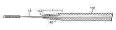
- an alternate embodiment of the sheath 100may comprise a soft, resilient and flexible atraumatic tip 140 , having an axial length L and that may comprise soft plastic or soft rubber to facilitate steering the sheath 100 and accompanying guide wire 15 through vasculature with improved atraumatic results.
- the atraumatic tip 140is shown comprising a taper which, in addition to facilitating steering the sheath 100 and guide wire 15 through vasculature, may further facilitate movement of the sheath 100 and guide wire 15 through an occluded lesion with less trauma than a sheath 100 without tip 140 .
- the atraumatic tip 140may not require a taper, instead utilizing soft plastic and/or thinner walls to create the desired resilience and flexibility.
- Atraumatic tip 140may be resilient enough to easily bend around turns and contortions of the vasculature, essentially leading the sheath 100 and guide wire 15 through the vasculature without damaging the side walls of the lumen in the process.
- Sheath 100may be comprised of a less soft and/or less resilient material than atraumatic tip 140 .
- sheath 100may comprise the same material as atraumatic tip 140 , wherein the softness and resilience between sheath 100 and tip 140 are substantially equivalent.
- the thickness of the walls of sheath 100 and tip 140may be substantially equivalent or tip 140 may comprise walls that are thinner than the walls of the sheath 100 . Such a configuration may provide additional flexibility to the tip 140 .
- the atraumatic tip 140may taper over a partial length (or in another embodiment over the entire length) in a variety of ways.
- the tapermay be created by progressively removing more material from the outer walls of the distal end of the sheath 100 , wherein the atraumatic tip 140 comprises walls of decreasing thickness in the distal direction.
- the distance or gap between guide wire 14 and the inner diameter of sheath 100may be decreased progressively along the distal end of sheath 100 .
- a combination of the two embodiments to create the taper just discussedmay be employed.
- the atraumatic tip 140 when compared with the relatively constant diameter of sheath 100 to which tip 140 is operatively coupledmay have a decreased, reduced, lesser, and/or smaller (individually and collectively, hereafter “smaller”) cross sectional area, mean diameter, perimeter, volume over a given length, thickness in height and width, and/or other smaller configuration, shape, form, profile, structure, external outline, and/or contour (individually and collectively, “cross sectional area”) during manufacturing, processing, molding, casting, forming, extruding, drawing and/or any combination thereof or equivalents thereto.
- small cross sectional areamean diameter, perimeter, volume over a given length, thickness in height and width
- Tip 140may taper all the way to the distal end 142 of tip 140 at a substantially constant angle.
- the tapering anglemay vary and/or may cease tapering before reaching the distal end 142 , leaving a distal-most nose portion of the tip 140 in the shape of a cylinder or the equivalent, i.e., a relatively constant diameter.
- Atraumatic tip 140is operably coupled with sheath 100 by methods well known to those skilled in the art.
- operatively couplingBy way of example only and not by way of limitation, the terms “operatively coupling,” “operatively coupled,” “coupling,” “coupled,” and variants thereof as used herein describe embodiments of the invention having a point, position, region, section, area, volume, or configuration at which two or more things are mechanically, chemically, and/or chemical-mechanically bonded, joined, adjoined, connected, associated, united, mated, interlocked, conjoined, fastened, held together, clamped, crimped, friction fit, pinched, press fit tight, nested, wedged, and/or otherwise associated by a joint, a junction, a juncture, a seam, a union, a socket, a melt bond, glue, adhesives, resins, welding (laser, spot, etc.), soldering, brazing, adhesives, chemical bonding materials, implanted arrangement, or combinations thereof.
- the sheath 100 and/or atraumatic tip 140may be manufactured of plastic material, preferably a polymer, such as TEFLON TM, polyolefin or polyurethane, having a low-friction surface or which is amenable to coating with a low-friction material.
- plastic materialpreferably a polymer, such as TEFLON TM, polyolefin or polyurethane, having a low-friction surface or which is amenable to coating with a low-friction material.
- suitable materialsmay include a sheath 100 formed of lubricious PTFE, polyester, polycarbonate, polyvinylchloride, latex, silicon rubber, polystyrene and polyacrylic.
- Surface coatings, if used,may comprise materials that comprise low-friction and/or which may be highly hydrophilic.
- Such coatingsmay be formed of polyvinylpyrrolidone (PVP), polyethyleneoxide or polyhydroxyethylmethacrylate (polyHEMA) or copolymers thereof.
- PVPpolyvinylpyrrolidone
- polyHEMApolyhydroxyethylmethacrylate
- the sheath 100 material and/or coatingmay be formed of lubricious materials.
- the sheath 100may further be comprised of stainless steel.
- Atraumatic tip 140may comprise a striated section 105 as discussed above.
- at least one striated section 105may cover the non-tapered section of sheath, in combination with atraumatic tip 140 which may, or in an alternate embodiment may not, comprise a striated section 105 .
- a method for maximizing efficiency of tissue removal from body passagewaysmay comprise: providing a device for opening occluded lesions; providing a guide wire with introducer sheath; pre-positioning guide wire with introducer sheath; axially moving guide wire and introducer sheath to expose guide wire's helically wound tip; advancing the device for opening occluded lesions distally along the guide wire and sheath to the desired location; opening the occluded lesion.
Landscapes
- Health & Medical Sciences (AREA)
- Life Sciences & Earth Sciences (AREA)
- Animal Behavior & Ethology (AREA)
- General Health & Medical Sciences (AREA)
- Veterinary Medicine (AREA)
- Engineering & Computer Science (AREA)
- Biomedical Technology (AREA)
- Heart & Thoracic Surgery (AREA)
- Public Health (AREA)
- Surgery (AREA)
- Biophysics (AREA)
- Pulmonology (AREA)
- Anesthesiology (AREA)
- Hematology (AREA)
- Molecular Biology (AREA)
- Vascular Medicine (AREA)
- Medical Informatics (AREA)
- Nuclear Medicine, Radiotherapy & Molecular Imaging (AREA)
- Surgical Instruments (AREA)
- Media Introduction/Drainage Providing Device (AREA)
Abstract
Description
Claims (23)
Priority Applications (8)
| Application Number | Priority Date | Filing Date | Title |
|---|---|---|---|
| US11/767,725US8439937B2 (en) | 2007-06-25 | 2007-06-25 | System, apparatus and method for opening an occluded lesion |
| EP08771806.0AEP2160138B1 (en) | 2007-06-25 | 2008-06-24 | System and apparatus for opening an occluded lesion |
| CA2687567ACA2687567C (en) | 2007-06-25 | 2008-06-24 | System, apparatus and method for opening an occluded lesion |
| CN200880021641.8ACN101686837B (en) | 2007-06-25 | 2008-06-24 | Systems for unclogging clogged lesions |
| ES08771806.0TES2565981T3 (en) | 2007-06-25 | 2008-06-24 | System and apparatus to open an occluded lesion |
| PCT/US2008/067999WO2009002971A1 (en) | 2007-06-25 | 2008-06-24 | System, apparatus and method for opening an occluded lesion |
| AU2008268410AAU2008268410B2 (en) | 2007-06-25 | 2008-06-24 | System, apparatus and method for opening an occluded lesion |
| JP2010513496AJP5599307B2 (en) | 2007-06-25 | 2008-06-24 | System, apparatus and method for opening an occlusive lesion |
Applications Claiming Priority (1)
| Application Number | Priority Date | Filing Date | Title |
|---|---|---|---|
| US11/767,725US8439937B2 (en) | 2007-06-25 | 2007-06-25 | System, apparatus and method for opening an occluded lesion |
Publications (2)
| Publication Number | Publication Date |
|---|---|
| US20080319462A1 US20080319462A1 (en) | 2008-12-25 |
| US8439937B2true US8439937B2 (en) | 2013-05-14 |
Family
ID=40137290
Family Applications (1)
| Application Number | Title | Priority Date | Filing Date |
|---|---|---|---|
| US11/767,725Expired - Fee RelatedUS8439937B2 (en) | 2007-06-25 | 2007-06-25 | System, apparatus and method for opening an occluded lesion |
Country Status (7)
| Country | Link |
|---|---|
| US (1) | US8439937B2 (en) |
| EP (1) | EP2160138B1 (en) |
| JP (1) | JP5599307B2 (en) |
| CN (1) | CN101686837B (en) |
| CA (1) | CA2687567C (en) |
| ES (1) | ES2565981T3 (en) |
| WO (1) | WO2009002971A1 (en) |
Cited By (23)
| Publication number | Priority date | Publication date | Assignee | Title |
|---|---|---|---|---|
| US20100305475A1 (en)* | 2007-04-23 | 2010-12-02 | Hinchliffe Peter W J | Guidewire with adjustable stiffness |
| WO2015013590A1 (en) | 2013-07-26 | 2015-01-29 | Cardiovascular Systems, Inc. | Devices, systems and methods for performing atherectomy and subsequent balloon angioplasty without exchanging devices |
| US20150119847A1 (en)* | 2013-10-29 | 2015-04-30 | Medwerks, Llc | Atraumatic Guidewire And Method Of Use |
| USD766433S1 (en) | 2013-11-04 | 2016-09-13 | Cardiovascular Systems, Inc. | Eccentric crown |
| US9622762B2 (en) | 2013-09-18 | 2017-04-18 | Xablecath Inc. | Catheter devices for crossing and treating an occlusion |
| US9855070B2 (en) | 2014-03-12 | 2018-01-02 | Boston Scientific Limited | Infusion lubricated atherectomy catheter |
| US10271869B2 (en) | 2014-03-01 | 2019-04-30 | Rex Medical, L.P. | Atherectomy device |
| US10307175B2 (en) | 2016-03-26 | 2019-06-04 | Rex Medical, L.P | Atherectomy device |
| US10405878B2 (en) | 2014-07-25 | 2019-09-10 | Boston Scientific Scimed, Inc. | Rotatable medical device |
| US10405879B2 (en) | 2014-12-04 | 2019-09-10 | Boston Scientific Scimed, Inc. | Rotatable medical device |
| US10433868B2 (en) | 2014-12-27 | 2019-10-08 | Rex Medical, L.P. | Artherectomy device |
| US10463389B2 (en) | 2014-12-27 | 2019-11-05 | Rex Medical, L.P. | Atherectomy device |
| US10668258B1 (en) | 2018-12-31 | 2020-06-02 | J.D. Franco & Co., Llc | Intravascular devices, systems, and methods to address eye disorders |
| US10751215B2 (en) | 2012-08-03 | 2020-08-25 | J.D. Franco & Co., Llc | Systems and methods for treating eye diseases |
| US10869689B2 (en) | 2017-05-03 | 2020-12-22 | Medtronic Vascular, Inc. | Tissue-removing catheter |
| US11253292B2 (en) | 2015-09-13 | 2022-02-22 | Rex Medical, L.P. | Atherectomy device |
| US11357534B2 (en) | 2018-11-16 | 2022-06-14 | Medtronic Vascular, Inc. | Catheter |
| US11529130B2 (en) | 2017-01-25 | 2022-12-20 | J.D. Franco & Co., Llc | Blood vessel access and closure devices and related methods of use |
| US11690645B2 (en) | 2017-05-03 | 2023-07-04 | Medtronic Vascular, Inc. | Tissue-removing catheter |
| US11701255B2 (en) | 2017-10-06 | 2023-07-18 | J.D. Franco & Co., Llc | Treating eye diseases by deploying a stent |
| US11759218B2 (en) | 2017-12-15 | 2023-09-19 | J.D. Franco & Co., Llc | Medical systems, devices, and related methods |
| US11819236B2 (en) | 2019-05-17 | 2023-11-21 | Medtronic Vascular, Inc. | Tissue-removing catheter |
| EP4509070A2 (en) | 2015-02-20 | 2025-02-19 | Cardiovascular Systems, Inc. | Methods and systems for disrupting calcified walls of biological conduits and calcified lesions therein |
Families Citing this family (14)
| Publication number | Priority date | Publication date | Assignee | Title |
|---|---|---|---|---|
| US8414543B2 (en) | 1999-10-22 | 2013-04-09 | Rex Medical, L.P. | Rotational thrombectomy wire with blocking device |
| US9603545B2 (en)* | 2003-02-21 | 2017-03-28 | 3Dt Holdings, Llc | Devices, systems, and methods for removing targeted lesions from vessels |
| US7819887B2 (en) | 2004-11-17 | 2010-10-26 | Rex Medical, L.P. | Rotational thrombectomy wire |
| US9510844B2 (en)* | 2007-11-13 | 2016-12-06 | Mgd Innovations, Llc | Gland or duct diagnostic and treatment methods and related apparatus |
| US8663259B2 (en) | 2010-05-13 | 2014-03-04 | Rex Medical L.P. | Rotational thrombectomy wire |
| US9795406B2 (en) | 2010-05-13 | 2017-10-24 | Rex Medical, L.P. | Rotational thrombectomy wire |
| US9023070B2 (en) | 2010-05-13 | 2015-05-05 | Rex Medical, L.P. | Rotational thrombectomy wire coupler |
| US8764779B2 (en) | 2010-05-13 | 2014-07-01 | Rex Medical, L.P. | Rotational thrombectomy wire |
| EP2517658B1 (en)* | 2011-04-27 | 2013-12-04 | Rex Medical, L.P. | Rotational thrombectomy wire |
| US9750525B2 (en)* | 2013-03-14 | 2017-09-05 | Cardiovascular Systems, Inc. | Devices, systems and methods for an oscillating crown drive for rotational atherectomy |
| WO2016133932A1 (en)* | 2015-02-18 | 2016-08-25 | Xablecath Inc. | Dual end systems and methods for crossing and treating an occlusion |
| CA2994368A1 (en)* | 2015-08-23 | 2017-03-02 | CardioSert Ltd. | Double concentric guidewire |
| EP3595538A4 (en)* | 2017-03-14 | 2020-12-23 | PRC Cardio-Optic | SYSTEMS AND PROCEDURES FOR NAVIGATING, OPENING AND CLEANING PLAQUE OR COMPLETE OCCLUSION IN ARTERIES |
| CN110840527B (en)* | 2019-12-06 | 2021-05-07 | 昆山金泰医疗科技有限公司 | Device for quickly cutting thrombus plaques |
Citations (24)
| Publication number | Priority date | Publication date | Assignee | Title |
|---|---|---|---|---|
| US4884579A (en)* | 1988-04-18 | 1989-12-05 | Target Therapeutics | Catheter guide wire |
| EP0480427A1 (en) | 1990-10-12 | 1992-04-15 | Nippon Seisen Co., Ltd. | Guide wire for a catheter |
| US5273526A (en) | 1991-06-21 | 1993-12-28 | Lake Region Manufacturing Company, Inc. | Vascular occulusion removal devices and method |
| US5314438A (en) | 1992-12-17 | 1994-05-24 | Shturman Cardiology Systems, Inc. | Abrasive drive shaft device for rotational atherectomy |
| US5376077A (en)* | 1992-12-04 | 1994-12-27 | Interventional Technologies, Inc. | Introducer sheath with seal protector |
| US5605162A (en) | 1991-10-15 | 1997-02-25 | Advanced Cardiovascular Systems, Inc. | Method for using a variable stiffness guidewire |
| WO1997043949A1 (en) | 1996-05-24 | 1997-11-27 | Sarcos, Inc. | Hybrid tubular guide wire for catheters |
| US6059767A (en)* | 1998-02-25 | 2000-05-09 | Norborn Medical, Inc. | Steerable unitary infusion catheter/guide wire incorporating detachable infusion port assembly |
| JP2000254235A (en) | 1999-03-10 | 2000-09-19 | Terumo Corp | Medical tube and its manufacture |
| US20010021831A1 (en) | 1987-09-30 | 2001-09-13 | Lake Region Manufacturing, Inc. | Hollow lumen cable apparatus |
| US6328750B1 (en)* | 1997-03-06 | 2001-12-11 | Scimed Life Systems, Inc. | Trifilar atherectomy driveshaft |
| US6447507B1 (en) | 1997-11-12 | 2002-09-10 | Daig Corporation | Rail catheter ablation and mapping system |
| US6494890B1 (en)* | 1997-08-14 | 2002-12-17 | Shturman Cardiology Systems, Inc. | Eccentric rotational atherectomy device |
| US20030069522A1 (en)* | 1995-12-07 | 2003-04-10 | Jacobsen Stephen J. | Slotted medical device |
| US20030125756A1 (en)* | 2001-10-19 | 2003-07-03 | Leonid Shturman | Rotational angioplasty device with abrasive crown |
| WO2004060463A1 (en) | 2002-12-23 | 2004-07-22 | Boston Scientific Limited | Guide catheter for introduction into the subarachnoid space and methods of use thereof |
| US6824550B1 (en) | 2000-04-06 | 2004-11-30 | Norbon Medical, Inc. | Guidewire for crossing occlusions or stenosis |
| US20050033334A1 (en)* | 2003-05-12 | 2005-02-10 | Swadeshmukul Santra | Devices and methods for disruption and removal of luminal occlusions |
| JP2005230550A (en) | 2004-02-20 | 2005-09-02 | Siemens Ag | Device for performing and monitoring rotabration |
| US20050283179A1 (en) | 2004-06-17 | 2005-12-22 | Lentz David J | Introducer sheath |
| US20060047222A1 (en)* | 2003-08-27 | 2006-03-02 | Heuser Richard R | Catheter guidewire system using concentric wires |
| US20060074442A1 (en)* | 2000-04-06 | 2006-04-06 | Revascular Therapeutics, Inc. | Guidewire for crossing occlusions or stenoses |
| US20080071303A1 (en)* | 2006-07-11 | 2008-03-20 | Randall Lee Hacker | Rotary shaver with improved connection between flexible and rigid rotatable tubes |
| US20100010499A1 (en)* | 2008-07-10 | 2010-01-14 | Cook Incorporated | Hydraulic guidewire advancement system |
Family Cites Families (3)
| Publication number | Priority date | Publication date | Assignee | Title |
|---|---|---|---|---|
| US6511492B1 (en)* | 1998-05-01 | 2003-01-28 | Microvention, Inc. | Embolectomy catheters and methods for treating stroke and other small vessel thromboembolic disorders |
| JP4445618B2 (en)* | 1999-11-15 | 2010-04-07 | 株式会社ハイレックスコーポレーション | Medical tube |
| JP3694312B1 (en)* | 2005-01-26 | 2005-09-14 | 朝日インテック株式会社 | Medical guidewire |
- 2007
- 2007-06-25USUS11/767,725patent/US8439937B2/ennot_activeExpired - Fee Related
- 2008
- 2008-06-24ESES08771806.0Tpatent/ES2565981T3/enactiveActive
- 2008-06-24EPEP08771806.0Apatent/EP2160138B1/ennot_activeNot-in-force
- 2008-06-24JPJP2010513496Apatent/JP5599307B2/ennot_activeExpired - Fee Related
- 2008-06-24CNCN200880021641.8Apatent/CN101686837B/ennot_activeExpired - Fee Related
- 2008-06-24CACA2687567Apatent/CA2687567C/ennot_activeExpired - Fee Related
- 2008-06-24WOPCT/US2008/067999patent/WO2009002971A1/enactiveApplication Filing
Patent Citations (27)
| Publication number | Priority date | Publication date | Assignee | Title |
|---|---|---|---|---|
| US20010021831A1 (en) | 1987-09-30 | 2001-09-13 | Lake Region Manufacturing, Inc. | Hollow lumen cable apparatus |
| US4884579A (en)* | 1988-04-18 | 1989-12-05 | Target Therapeutics | Catheter guide wire |
| EP0480427A1 (en) | 1990-10-12 | 1992-04-15 | Nippon Seisen Co., Ltd. | Guide wire for a catheter |
| US5273526A (en) | 1991-06-21 | 1993-12-28 | Lake Region Manufacturing Company, Inc. | Vascular occulusion removal devices and method |
| US5605162A (en) | 1991-10-15 | 1997-02-25 | Advanced Cardiovascular Systems, Inc. | Method for using a variable stiffness guidewire |
| US5376077A (en)* | 1992-12-04 | 1994-12-27 | Interventional Technologies, Inc. | Introducer sheath with seal protector |
| US5314438A (en) | 1992-12-17 | 1994-05-24 | Shturman Cardiology Systems, Inc. | Abrasive drive shaft device for rotational atherectomy |
| US20030069522A1 (en)* | 1995-12-07 | 2003-04-10 | Jacobsen Stephen J. | Slotted medical device |
| WO1997043949A1 (en) | 1996-05-24 | 1997-11-27 | Sarcos, Inc. | Hybrid tubular guide wire for catheters |
| US6017319A (en)* | 1996-05-24 | 2000-01-25 | Precision Vascular Systems, Inc. | Hybrid tubular guide wire for catheters |
| US6328750B1 (en)* | 1997-03-06 | 2001-12-11 | Scimed Life Systems, Inc. | Trifilar atherectomy driveshaft |
| US6494890B1 (en)* | 1997-08-14 | 2002-12-17 | Shturman Cardiology Systems, Inc. | Eccentric rotational atherectomy device |
| US6447507B1 (en) | 1997-11-12 | 2002-09-10 | Daig Corporation | Rail catheter ablation and mapping system |
| US6059767A (en)* | 1998-02-25 | 2000-05-09 | Norborn Medical, Inc. | Steerable unitary infusion catheter/guide wire incorporating detachable infusion port assembly |
| JP2000254235A (en) | 1999-03-10 | 2000-09-19 | Terumo Corp | Medical tube and its manufacture |
| US20060074442A1 (en)* | 2000-04-06 | 2006-04-06 | Revascular Therapeutics, Inc. | Guidewire for crossing occlusions or stenoses |
| US6824550B1 (en) | 2000-04-06 | 2004-11-30 | Norbon Medical, Inc. | Guidewire for crossing occlusions or stenosis |
| US20030125756A1 (en)* | 2001-10-19 | 2003-07-03 | Leonid Shturman | Rotational angioplasty device with abrasive crown |
| WO2004012804A2 (en) | 2002-08-05 | 2004-02-12 | Boston Scientific Limited | Medical device with collapse-resistant liner and method of making same |
| WO2004060463A1 (en) | 2002-12-23 | 2004-07-22 | Boston Scientific Limited | Guide catheter for introduction into the subarachnoid space and methods of use thereof |
| US20050033334A1 (en)* | 2003-05-12 | 2005-02-10 | Swadeshmukul Santra | Devices and methods for disruption and removal of luminal occlusions |
| US20060047222A1 (en)* | 2003-08-27 | 2006-03-02 | Heuser Richard R | Catheter guidewire system using concentric wires |
| US20050203553A1 (en) | 2004-02-20 | 2005-09-15 | Siemens Aktiengesellschaft | Device for the performance and monitoring of rotablation |
| JP2005230550A (en) | 2004-02-20 | 2005-09-02 | Siemens Ag | Device for performing and monitoring rotabration |
| US20050283179A1 (en) | 2004-06-17 | 2005-12-22 | Lentz David J | Introducer sheath |
| US20080071303A1 (en)* | 2006-07-11 | 2008-03-20 | Randall Lee Hacker | Rotary shaver with improved connection between flexible and rigid rotatable tubes |
| US20100010499A1 (en)* | 2008-07-10 | 2010-01-14 | Cook Incorporated | Hydraulic guidewire advancement system |
Cited By (56)
| Publication number | Priority date | Publication date | Assignee | Title |
|---|---|---|---|---|
| US20100305475A1 (en)* | 2007-04-23 | 2010-12-02 | Hinchliffe Peter W J | Guidewire with adjustable stiffness |
| US9387308B2 (en)* | 2007-04-23 | 2016-07-12 | Cardioguidance Biomedical, Llc | Guidewire with adjustable stiffness |
| US12318327B2 (en) | 2012-08-03 | 2025-06-03 | J.D. Franco & Co., Llc | Systems and methods for treating eye diseases |
| US10751215B2 (en) | 2012-08-03 | 2020-08-25 | J.D. Franco & Co., Llc | Systems and methods for treating eye diseases |
| US11654047B2 (en) | 2012-08-03 | 2023-05-23 | J.D. Franco & Co., Llc | Systems and methods for treating eye diseases |
| WO2015013590A1 (en) | 2013-07-26 | 2015-01-29 | Cardiovascular Systems, Inc. | Devices, systems and methods for performing atherectomy and subsequent balloon angioplasty without exchanging devices |
| US9826995B2 (en) | 2013-09-18 | 2017-11-28 | XableCath, Inc. | Support catheters for use in crossing and treating an occlusion |
| US10499934B2 (en) | 2013-09-18 | 2019-12-10 | Xablecath Inc. | Methods for crossing and treating an occlusion |
| US10278715B2 (en) | 2013-09-18 | 2019-05-07 | Xablecath Inc. | Systems for use in crossing and treating an occlusion |
| US9622762B2 (en) | 2013-09-18 | 2017-04-18 | Xablecath Inc. | Catheter devices for crossing and treating an occlusion |
| US20150119847A1 (en)* | 2013-10-29 | 2015-04-30 | Medwerks, Llc | Atraumatic Guidewire And Method Of Use |
| USD766433S1 (en) | 2013-11-04 | 2016-09-13 | Cardiovascular Systems, Inc. | Eccentric crown |
| US10271869B2 (en) | 2014-03-01 | 2019-04-30 | Rex Medical, L.P. | Atherectomy device |
| US10751083B2 (en) | 2014-03-01 | 2020-08-25 | Rex Medical L.P. | Atherectomy device |
| US10595893B2 (en) | 2014-03-12 | 2020-03-24 | Boston Scientific Limited | Infusion lubricated atherectomy catheter |
| US11497522B2 (en) | 2014-03-12 | 2022-11-15 | Boston Scientific Limited | Infusion lubricated atherectomy catheter |
| US9855070B2 (en) | 2014-03-12 | 2018-01-02 | Boston Scientific Limited | Infusion lubricated atherectomy catheter |
| US12318111B2 (en) | 2014-03-12 | 2025-06-03 | Boston Scientific Medical Device Limited | Infusion lubricated atherectomy catheter |
| US10405878B2 (en) | 2014-07-25 | 2019-09-10 | Boston Scientific Scimed, Inc. | Rotatable medical device |
| US12185969B2 (en) | 2014-12-04 | 2025-01-07 | Boston Scientific Scimed, Inc. | Rotatable medical device |
| US10405879B2 (en) | 2014-12-04 | 2019-09-10 | Boston Scientific Scimed, Inc. | Rotatable medical device |
| US11596437B2 (en) | 2014-12-04 | 2023-03-07 | Boston Scientific Scimed, Inc. | Rotatable medical device |
| US11547434B2 (en) | 2014-12-27 | 2023-01-10 | Rex Medical L.P. | Atherectomy device |
| US10463389B2 (en) | 2014-12-27 | 2019-11-05 | Rex Medical, L.P. | Atherectomy device |
| US11426194B2 (en) | 2014-12-27 | 2022-08-30 | Rex Medical L.P. | Atherectomy device |
| US10433868B2 (en) | 2014-12-27 | 2019-10-08 | Rex Medical, L.P. | Artherectomy device |
| EP4509070A2 (en) | 2015-02-20 | 2025-02-19 | Cardiovascular Systems, Inc. | Methods and systems for disrupting calcified walls of biological conduits and calcified lesions therein |
| US12274822B2 (en) | 2015-09-13 | 2025-04-15 | Rex Medical, L.P. | Atherectomy device |
| US11253292B2 (en) | 2015-09-13 | 2022-02-22 | Rex Medical, L.P. | Atherectomy device |
| US10307175B2 (en) | 2016-03-26 | 2019-06-04 | Rex Medical, L.P | Atherectomy device |
| US11020134B2 (en) | 2016-03-26 | 2021-06-01 | Rex Meddical L.P. | Atherectomy device |
| US11864780B2 (en) | 2016-03-26 | 2024-01-09 | Rex Medical, L.P. | Atherectomy device |
| US11529130B2 (en) | 2017-01-25 | 2022-12-20 | J.D. Franco & Co., Llc | Blood vessel access and closure devices and related methods of use |
| US11925339B2 (en) | 2017-01-25 | 2024-03-12 | J.D. Franco & Co., Llc | Blood vessel access and closure devices and related methods of use |
| US10987126B2 (en) | 2017-05-03 | 2021-04-27 | Medtronic Vascular, Inc. | Tissue-removing catheter with guidewire isolation liner |
| US10869689B2 (en) | 2017-05-03 | 2020-12-22 | Medtronic Vascular, Inc. | Tissue-removing catheter |
| US11051842B2 (en) | 2017-05-03 | 2021-07-06 | Medtronic Vascular, Inc. | Tissue-removing catheter with guidewire isolation liner |
| US12114887B2 (en) | 2017-05-03 | 2024-10-15 | Medtronic Vascular, Inc. | Tissue-removing catheter with guidewire isolation liner |
| US10925632B2 (en) | 2017-05-03 | 2021-02-23 | Medtronic Vascular, Inc. | Tissue-removing catheter |
| US11690645B2 (en) | 2017-05-03 | 2023-07-04 | Medtronic Vascular, Inc. | Tissue-removing catheter |
| US11986207B2 (en) | 2017-05-03 | 2024-05-21 | Medtronic Vascular, Inc. | Tissue-removing catheter with guidewire isolation liner |
| US11896260B2 (en) | 2017-05-03 | 2024-02-13 | Medtronic Vascular, Inc. | Tissue-removing catheter |
| US11871958B2 (en) | 2017-05-03 | 2024-01-16 | Medtronic Vascular, Inc. | Tissue-removing catheter with guidewire isolation liner |
| US11701255B2 (en) | 2017-10-06 | 2023-07-18 | J.D. Franco & Co., Llc | Treating eye diseases by deploying a stent |
| US11759218B2 (en) | 2017-12-15 | 2023-09-19 | J.D. Franco & Co., Llc | Medical systems, devices, and related methods |
| US11357534B2 (en) | 2018-11-16 | 2022-06-14 | Medtronic Vascular, Inc. | Catheter |
| US12161359B2 (en) | 2018-11-16 | 2024-12-10 | Medtronic Vascular, Inc. | Catheter |
| US10814109B2 (en) | 2018-12-31 | 2020-10-27 | J.D. Franco & Co., Llc | Intravascular devices, systems, and methods to address eye disorders |
| US10933226B2 (en) | 2018-12-31 | 2021-03-02 | J.D. Franco & Co., Llc | Intravascular devices, systems, and methods to address eye disorders |
| US12161825B2 (en) | 2018-12-31 | 2024-12-10 | J.D. Franco & Co., Llc | Intravascular devices, systems, and methods to address eye disorders |
| US10799688B2 (en) | 2018-12-31 | 2020-10-13 | J.D. Franco & Co., Llc | Intravascular devices, systems, and methods to address eye disorders |
| US10792478B2 (en) | 2018-12-31 | 2020-10-06 | J.D. Franco & Co., Llc | Intravascular devices, systems, and methods to address eye disorders |
| US10765843B2 (en) | 2018-12-31 | 2020-09-08 | J.D. Franco & Co., Llc | Intravascular devices, systems, and methods to address eye disorders |
| US10695541B1 (en) | 2018-12-31 | 2020-06-30 | J.D. Franco & Co., Llc | Intravascular devices, systems, and methods to address eye disorders |
| US10668258B1 (en) | 2018-12-31 | 2020-06-02 | J.D. Franco & Co., Llc | Intravascular devices, systems, and methods to address eye disorders |
| US11819236B2 (en) | 2019-05-17 | 2023-11-21 | Medtronic Vascular, Inc. | Tissue-removing catheter |
Also Published As
| Publication number | Publication date |
|---|---|
| WO2009002971A1 (en) | 2008-12-31 |
| JP2010531170A (en) | 2010-09-24 |
| JP5599307B2 (en) | 2014-10-01 |
| CA2687567C (en) | 2013-04-02 |
| EP2160138A4 (en) | 2011-07-27 |
| CA2687567A1 (en) | 2008-12-31 |
| ES2565981T3 (en) | 2016-04-08 |
| EP2160138B1 (en) | 2016-01-06 |
| CN101686837B (en) | 2013-03-06 |
| EP2160138A1 (en) | 2010-03-10 |
| US20080319462A1 (en) | 2008-12-25 |
| CN101686837A (en) | 2010-03-31 |
| AU2008268410A1 (en) | 2008-12-31 |
Similar Documents
| Publication | Publication Date | Title |
|---|---|---|
| US8439937B2 (en) | System, apparatus and method for opening an occluded lesion | |
| US9254143B2 (en) | Guidewire for crossing occlusions or stenoses having a shapeable distal end | |
| US9113955B2 (en) | Guidewire for crossing occlusions or stenoses | |
| US20050119615A1 (en) | Guidewire for crossing occlusions or stenoses | |
| JP4890463B2 (en) | Guidewire for crossing an obstruction or stenosis | |
| US20030139689A1 (en) | High torque, low profile intravascular guidewire system | |
| US20080140101A1 (en) | Apparatus for crossing occlusions or stenoses | |
| JP2018525088A (en) | Double concentric guidewire | |
| JP2016533861A (en) | System and method for crossing and treating an obstruction | |
| JP2008501489A (en) | Steerable distal support system | |
| JP2010540072A (en) | Collection catheter | |
| US20240074782A1 (en) | Systems and methods for crossing and treating an occlusion | |
| AU2008268410B2 (en) | System, apparatus and method for opening an occluded lesion | |
| CA2488588C (en) | Guidewire for crossing occlusions or stenosis | |
| CN118302119A (en) | Tissue removal catheter with flexible distal tip | |
| CN118338855A (en) | Tissue-removing catheter having a flexible portion and a rigid portion |
Legal Events
| Date | Code | Title | Description |
|---|---|---|---|
| AS | Assignment | Owner name:CARDIOVASCULAR SYSTEMS, INC., MINNESOTA Free format text:ASSIGNMENT OF ASSIGNORS INTEREST;ASSIGNORS:MONTAGUE, JAMES ROBERT;BLACKLEDGE, VICTOR ROY;REEL/FRAME:019635/0108 Effective date:20070619 | |
| AS | Assignment | Owner name:PARTNERS FOR GROWTH III, L.P.,CALIFORNIA Free format text:SECURITY AGREEMENT;ASSIGNOR:CARDIOVASCULAR SYSTEMS, INC.;REEL/FRAME:024233/0346 Effective date:20100412 Owner name:PARTNERS FOR GROWTH III, L.P., CALIFORNIA Free format text:SECURITY AGREEMENT;ASSIGNOR:CARDIOVASCULAR SYSTEMS, INC.;REEL/FRAME:024233/0346 Effective date:20100412 | |
| AS | Assignment | Owner name:CARDIOVASCULAR SYSTEMS, INC., MINNESOTA Free format text:RELEASE BY SECURED PARTY;ASSIGNOR:PARTNERS FOR GROWTH III, L.P.;REEL/FRAME:035678/0128 Effective date:20150427 | |
| REMI | Maintenance fee reminder mailed | ||
| LAPS | Lapse for failure to pay maintenance fees | ||
| STCH | Information on status: patent discontinuation | Free format text:PATENT EXPIRED DUE TO NONPAYMENT OF MAINTENANCE FEES UNDER 37 CFR 1.362 | |
| FP | Lapsed due to failure to pay maintenance fee | Effective date:20170514 |