US8439905B2 - Nucleation enhanced surface modification to support physical vapor deposition to create a vacuum - Google Patents
Nucleation enhanced surface modification to support physical vapor deposition to create a vacuumDownload PDFInfo
- Publication number
- US8439905B2 US8439905B2US12/562,301US56230109AUS8439905B2US 8439905 B2US8439905 B2US 8439905B2US 56230109 AUS56230109 AUS 56230109AUS 8439905 B2US8439905 B2US 8439905B2
- Authority
- US
- United States
- Prior art keywords
- product
- longitudinal body
- distal end
- outer surfaces
- internal
- Prior art date
- Legal status (The legal status is an assumption and is not a legal conclusion. Google has not performed a legal analysis and makes no representation as to the accuracy of the status listed.)
- Active, expires
Links
- 230000006911nucleationEffects0.000titleclaimsabstractdescription20
- 238000010899nucleationMethods0.000titleclaimsabstractdescription20
- 230000004048modificationEffects0.000titleclaimsdescription13
- 238000012986modificationMethods0.000titleclaimsdescription13
- 238000005240physical vapour depositionMethods0.000titledescription2
- 230000008014freezingEffects0.000claimsabstractdescription27
- 238000007710freezingMethods0.000claimsabstractdescription27
- 239000000523sampleSubstances0.000claimsabstractdescription22
- 238000001816coolingMethods0.000claimsabstractdescription8
- 229920006395saturated elastomerPolymers0.000claimsabstractdescription8
- 238000000034methodMethods0.000claimsdescription28
- 239000007788liquidSubstances0.000claimsdescription18
- 230000008569processEffects0.000claimsdescription8
- 230000008859changeEffects0.000claimsdescription7
- 239000002245particleSubstances0.000claimsdescription6
- 239000000126substanceSubstances0.000claimsdescription6
- 230000015572biosynthetic processEffects0.000claimsdescription5
- 230000001419dependent effectEffects0.000claimsdescription4
- 238000005530etchingMethods0.000claimsdescription4
- 239000011248coating agentSubstances0.000claimsdescription3
- 238000000576coating methodMethods0.000claimsdescription3
- 239000006260foamSubstances0.000claimsdescription3
- 238000007789sealingMethods0.000claimsdescription3
- 125000006850spacer groupChemical group0.000claimsdescription3
- 239000012535impuritySubstances0.000claimsdescription2
- 238000012634optical imagingMethods0.000claimsdescription2
- 238000012544monitoring processMethods0.000claims1
- 238000005289physical depositionMethods0.000claims1
- 230000001376precipitating effectEffects0.000claims1
- 238000009413insulationMethods0.000abstractdescription14
- 230000003389potentiating effectEffects0.000abstractdescription2
- 239000007789gasSubstances0.000description20
- 210000001519tissueAnatomy0.000description20
- 238000011282treatmentMethods0.000description17
- 230000008021depositionEffects0.000description9
- 238000000151depositionMethods0.000description9
- IJGRMHOSHXDMSA-UHFFFAOYSA-NAtomic nitrogenChemical compoundN#NIJGRMHOSHXDMSA-UHFFFAOYSA-N0.000description8
- 201000010099diseaseDiseases0.000description7
- 208000037265diseases, disorders, signs and symptomsDiseases0.000description7
- 230000004888barrier functionEffects0.000description6
- 238000000315cryotherapyMethods0.000description6
- 230000006872improvementEffects0.000description6
- 238000013461designMethods0.000description5
- 238000002560therapeutic procedureMethods0.000description5
- VYPSYNLAJGMNEJ-UHFFFAOYSA-NSilicium dioxideChemical compoundO=[Si]=OVYPSYNLAJGMNEJ-UHFFFAOYSA-N0.000description4
- 230000008901benefitEffects0.000description4
- 239000013078crystalSubstances0.000description4
- 230000000694effectsEffects0.000description4
- 239000000463materialSubstances0.000description4
- 239000000203mixtureSubstances0.000description4
- 229910052757nitrogenInorganic materials0.000description4
- 230000001052transient effectEffects0.000description4
- 238000005137deposition processMethods0.000description3
- 230000009977dual effectEffects0.000description3
- 230000008029eradicationEffects0.000description3
- 230000006870functionEffects0.000description3
- 230000002980postoperative effectEffects0.000description3
- CURLTUGMZLYLDI-UHFFFAOYSA-NCarbon dioxideChemical compoundO=C=OCURLTUGMZLYLDI-UHFFFAOYSA-N0.000description2
- 206010028980NeoplasmDiseases0.000description2
- GQPLMRYTRLFLPF-UHFFFAOYSA-NNitrous OxideChemical compound[O-][N+]#NGQPLMRYTRLFLPF-UHFFFAOYSA-N0.000description2
- 238000013459approachMethods0.000description2
- 239000001273butaneSubstances0.000description2
- 230000000747cardiac effectEffects0.000description2
- 230000003247decreasing effectEffects0.000description2
- IJDNQMDRQITEOD-UHFFFAOYSA-Nn-butaneChemical compoundCCCCIJDNQMDRQITEOD-UHFFFAOYSA-N0.000description2
- OFBQJSOFQDEBGM-UHFFFAOYSA-Nn-pentaneNatural productsCCCCCOFBQJSOFQDEBGM-UHFFFAOYSA-N0.000description2
- 239000004033plasticSubstances0.000description2
- 229920003023plasticPolymers0.000description2
- 238000011084recoveryMethods0.000description2
- 239000000377silicon dioxideSubstances0.000description2
- 238000001356surgical procedureMethods0.000description2
- DSSYKIVIOFKYAU-XCBNKYQSSA-N(R)-camphorChemical compoundC1C[C@@]2(C)C(=O)C[C@@H]1C2(C)CDSSYKIVIOFKYAU-XCBNKYQSSA-N0.000description1
- OKTJSMMVPCPJKN-UHFFFAOYSA-NCarbonChemical compound[C]OKTJSMMVPCPJKN-UHFFFAOYSA-N0.000description1
- 208000024172Cardiovascular diseaseDiseases0.000description1
- 241000723346Cinnamomum camphoraSpecies0.000description1
- 208000002193PainDiseases0.000description1
- 206010038848Retinal detachmentDiseases0.000description1
- 229920006328StyrofoamPolymers0.000description1
- 208000027418Wounds and injuryDiseases0.000description1
- 229960000846camphorDrugs0.000description1
- 229930008380camphorNatural products0.000description1
- 201000011510cancerDiseases0.000description1
- 239000012830cancer therapeuticSubstances0.000description1
- 229910052799carbonInorganic materials0.000description1
- 229910002092carbon dioxideInorganic materials0.000description1
- 239000001569carbon dioxideSubstances0.000description1
- 239000000919ceramicSubstances0.000description1
- 238000009833condensationMethods0.000description1
- 230000005494condensationEffects0.000description1
- 238000010276constructionMethods0.000description1
- 230000006378damageEffects0.000description1
- 238000011161developmentMethods0.000description1
- 230000007831electrophysiologyEffects0.000description1
- 238000002001electrophysiologyMethods0.000description1
- 238000005516engineering processMethods0.000description1
- 230000007613environmental effectEffects0.000description1
- 238000002692epidural anesthesiaMethods0.000description1
- 238000000605extractionMethods0.000description1
- 238000002695general anesthesiaMethods0.000description1
- 230000036541healthEffects0.000description1
- 208000014674injuryDiseases0.000description1
- PNDPGZBMCMUPRI-UHFFFAOYSA-NiodineChemical compoundIIPNDPGZBMCMUPRI-UHFFFAOYSA-N0.000description1
- 210000003734kidneyAnatomy0.000description1
- 210000004185liverAnatomy0.000description1
- 230000014759maintenance of locationEffects0.000description1
- 238000007726management methodMethods0.000description1
- -1metallicSubstances0.000description1
- 239000013528metallic particleSubstances0.000description1
- 230000036403neuro physiologyEffects0.000description1
- 239000001272nitrous oxideSubstances0.000description1
- 210000000056organAnatomy0.000description1
- 230000036407painEffects0.000description1
- 230000004962physiological conditionEffects0.000description1
- 210000002307prostateAnatomy0.000description1
- 238000001959radiotherapyMethods0.000description1
- 230000008707rearrangementEffects0.000description1
- 230000004264retinal detachmentEffects0.000description1
- 239000007787solidSubstances0.000description1
- 230000002269spontaneous effectEffects0.000description1
- 239000008261styrofoamSubstances0.000description1
- 238000000859sublimationMethods0.000description1
- 230000008022sublimationEffects0.000description1
- 230000008685targetingEffects0.000description1
- 238000009834vaporizationMethods0.000description1
- 230000008016vaporizationEffects0.000description1
Images


Classifications
- A—HUMAN NECESSITIES
- A61—MEDICAL OR VETERINARY SCIENCE; HYGIENE
- A61F—FILTERS IMPLANTABLE INTO BLOOD VESSELS; PROSTHESES; DEVICES PROVIDING PATENCY TO, OR PREVENTING COLLAPSING OF, TUBULAR STRUCTURES OF THE BODY, e.g. STENTS; ORTHOPAEDIC, NURSING OR CONTRACEPTIVE DEVICES; FOMENTATION; TREATMENT OR PROTECTION OF EYES OR EARS; BANDAGES, DRESSINGS OR ABSORBENT PADS; FIRST-AID KITS
- A61F7/00—Heating or cooling appliances for medical or therapeutic treatment of the human body
- A61F7/12—Devices for heating or cooling internal body cavities
- A—HUMAN NECESSITIES
- A61—MEDICAL OR VETERINARY SCIENCE; HYGIENE
- A61B—DIAGNOSIS; SURGERY; IDENTIFICATION
- A61B18/00—Surgical instruments, devices or methods for transferring non-mechanical forms of energy to or from the body
- A61B18/02—Surgical instruments, devices or methods for transferring non-mechanical forms of energy to or from the body by cooling, e.g. cryogenic techniques
- A—HUMAN NECESSITIES
- A61—MEDICAL OR VETERINARY SCIENCE; HYGIENE
- A61F—FILTERS IMPLANTABLE INTO BLOOD VESSELS; PROSTHESES; DEVICES PROVIDING PATENCY TO, OR PREVENTING COLLAPSING OF, TUBULAR STRUCTURES OF THE BODY, e.g. STENTS; ORTHOPAEDIC, NURSING OR CONTRACEPTIVE DEVICES; FOMENTATION; TREATMENT OR PROTECTION OF EYES OR EARS; BANDAGES, DRESSINGS OR ABSORBENT PADS; FIRST-AID KITS
- A61F7/00—Heating or cooling appliances for medical or therapeutic treatment of the human body
- A61F7/12—Devices for heating or cooling internal body cavities
- A61F7/123—Devices for heating or cooling internal body cavities using a flexible balloon containing the thermal element
- A—HUMAN NECESSITIES
- A61—MEDICAL OR VETERINARY SCIENCE; HYGIENE
- A61B—DIAGNOSIS; SURGERY; IDENTIFICATION
- A61B17/00—Surgical instruments, devices or methods
- A61B2017/00017—Electrical control of surgical instruments
- A61B2017/00022—Sensing or detecting at the treatment site
- A61B2017/00084—Temperature
- A—HUMAN NECESSITIES
- A61—MEDICAL OR VETERINARY SCIENCE; HYGIENE
- A61B—DIAGNOSIS; SURGERY; IDENTIFICATION
- A61B17/00—Surgical instruments, devices or methods
- A61B17/22—Implements for squeezing-off ulcers or the like on inner organs of the body; Implements for scraping-out cavities of body organs, e.g. bones; for invasive removal or destruction of calculus using mechanical vibrations; for removing obstructions in blood vessels, not otherwise provided for
- A61B2017/22051—Implements for squeezing-off ulcers or the like on inner organs of the body; Implements for scraping-out cavities of body organs, e.g. bones; for invasive removal or destruction of calculus using mechanical vibrations; for removing obstructions in blood vessels, not otherwise provided for with an inflatable part, e.g. balloon, for positioning, blocking, or immobilisation
- A—HUMAN NECESSITIES
- A61—MEDICAL OR VETERINARY SCIENCE; HYGIENE
- A61B—DIAGNOSIS; SURGERY; IDENTIFICATION
- A61B18/00—Surgical instruments, devices or methods for transferring non-mechanical forms of energy to or from the body
- A61B2018/00005—Cooling or heating of the probe or tissue immediately surrounding the probe
- A61B2018/00041—Heating, e.g. defrosting
- A—HUMAN NECESSITIES
- A61—MEDICAL OR VETERINARY SCIENCE; HYGIENE
- A61B—DIAGNOSIS; SURGERY; IDENTIFICATION
- A61B18/00—Surgical instruments, devices or methods for transferring non-mechanical forms of energy to or from the body
- A61B2018/00053—Mechanical features of the instrument of device
- A61B2018/00059—Material properties
- A61B2018/00089—Thermal conductivity
- A61B2018/00101—Thermal conductivity low, i.e. thermally insulating
- A—HUMAN NECESSITIES
- A61—MEDICAL OR VETERINARY SCIENCE; HYGIENE
- A61B—DIAGNOSIS; SURGERY; IDENTIFICATION
- A61B18/00—Surgical instruments, devices or methods for transferring non-mechanical forms of energy to or from the body
- A61B2018/00053—Mechanical features of the instrument of device
- A61B2018/00214—Expandable means emitting energy, e.g. by elements carried thereon
- A61B2018/0022—Balloons
- A—HUMAN NECESSITIES
- A61—MEDICAL OR VETERINARY SCIENCE; HYGIENE
- A61B—DIAGNOSIS; SURGERY; IDENTIFICATION
- A61B18/00—Surgical instruments, devices or methods for transferring non-mechanical forms of energy to or from the body
- A61B2018/00982—Surgical instruments, devices or methods for transferring non-mechanical forms of energy to or from the body combined with or comprising means for visual or photographic inspections inside the body, e.g. endoscopes
- A—HUMAN NECESSITIES
- A61—MEDICAL OR VETERINARY SCIENCE; HYGIENE
- A61B—DIAGNOSIS; SURGERY; IDENTIFICATION
- A61B18/00—Surgical instruments, devices or methods for transferring non-mechanical forms of energy to or from the body
- A61B18/02—Surgical instruments, devices or methods for transferring non-mechanical forms of energy to or from the body by cooling, e.g. cryogenic techniques
- A61B2018/0212—Surgical instruments, devices or methods for transferring non-mechanical forms of energy to or from the body by cooling, e.g. cryogenic techniques using an instrument inserted into a body lumen, e.g. catheter
- A—HUMAN NECESSITIES
- A61—MEDICAL OR VETERINARY SCIENCE; HYGIENE
- A61B—DIAGNOSIS; SURGERY; IDENTIFICATION
- A61B18/00—Surgical instruments, devices or methods for transferring non-mechanical forms of energy to or from the body
- A61B18/02—Surgical instruments, devices or methods for transferring non-mechanical forms of energy to or from the body by cooling, e.g. cryogenic techniques
- A61B2018/0231—Characteristics of handpieces or probes
- A61B2018/0262—Characteristics of handpieces or probes using a circulating cryogenic fluid
- A61B2018/0268—Characteristics of handpieces or probes using a circulating cryogenic fluid with restriction of flow
- A—HUMAN NECESSITIES
- A61—MEDICAL OR VETERINARY SCIENCE; HYGIENE
- A61B—DIAGNOSIS; SURGERY; IDENTIFICATION
- A61B90/00—Instruments, implements or accessories specially adapted for surgery or diagnosis and not covered by any of the groups A61B1/00 - A61B50/00, e.g. for luxation treatment or for protecting wound edges
- A61B90/06—Measuring instruments not otherwise provided for
- A61B2090/064—Measuring instruments not otherwise provided for for measuring force, pressure or mechanical tension
- A—HUMAN NECESSITIES
- A61—MEDICAL OR VETERINARY SCIENCE; HYGIENE
- A61B—DIAGNOSIS; SURGERY; IDENTIFICATION
- A61B5/00—Measuring for diagnostic purposes; Identification of persons
- A61B5/0059—Measuring for diagnostic purposes; Identification of persons using light, e.g. diagnosis by transillumination, diascopy, fluorescence
- A61B5/0082—Measuring for diagnostic purposes; Identification of persons using light, e.g. diagnosis by transillumination, diascopy, fluorescence adapted for particular medical purposes
- A61B5/0084—Measuring for diagnostic purposes; Identification of persons using light, e.g. diagnosis by transillumination, diascopy, fluorescence adapted for particular medical purposes for introduction into the body, e.g. by catheters
- A—HUMAN NECESSITIES
- A61—MEDICAL OR VETERINARY SCIENCE; HYGIENE
- A61B—DIAGNOSIS; SURGERY; IDENTIFICATION
- A61B5/00—Measuring for diagnostic purposes; Identification of persons
- A61B5/01—Measuring temperature of body parts ; Diagnostic temperature sensing, e.g. for malignant or inflamed tissue
- A—HUMAN NECESSITIES
- A61—MEDICAL OR VETERINARY SCIENCE; HYGIENE
- A61B—DIAGNOSIS; SURGERY; IDENTIFICATION
- A61B5/00—Measuring for diagnostic purposes; Identification of persons
- A61B5/03—Measuring fluid pressure within the body other than blood pressure, e.g. cerebral pressure ; Measuring pressure in body tissues or organs
- A61B5/036—Measuring fluid pressure within the body other than blood pressure, e.g. cerebral pressure ; Measuring pressure in body tissues or organs by means introduced into body tracts
- A—HUMAN NECESSITIES
- A61—MEDICAL OR VETERINARY SCIENCE; HYGIENE
- A61B—DIAGNOSIS; SURGERY; IDENTIFICATION
- A61B5/00—Measuring for diagnostic purposes; Identification of persons
- A61B5/24—Detecting, measuring or recording bioelectric or biomagnetic signals of the body or parts thereof
- A61B5/25—Bioelectric electrodes therefor
- A61B5/279—Bioelectric electrodes therefor specially adapted for particular uses
- A61B5/28—Bioelectric electrodes therefor specially adapted for particular uses for electrocardiography [ECG]
- A61B5/283—Invasive
- A61B5/287—Holders for multiple electrodes, e.g. electrode catheters for electrophysiological study [EPS]
- A—HUMAN NECESSITIES
- A61—MEDICAL OR VETERINARY SCIENCE; HYGIENE
- A61F—FILTERS IMPLANTABLE INTO BLOOD VESSELS; PROSTHESES; DEVICES PROVIDING PATENCY TO, OR PREVENTING COLLAPSING OF, TUBULAR STRUCTURES OF THE BODY, e.g. STENTS; ORTHOPAEDIC, NURSING OR CONTRACEPTIVE DEVICES; FOMENTATION; TREATMENT OR PROTECTION OF EYES OR EARS; BANDAGES, DRESSINGS OR ABSORBENT PADS; FIRST-AID KITS
- A61F7/00—Heating or cooling appliances for medical or therapeutic treatment of the human body
- A61F2007/0054—Heating or cooling appliances for medical or therapeutic treatment of the human body with a closed fluid circuit, e.g. hot water
- A61F2007/0056—Heating or cooling appliances for medical or therapeutic treatment of the human body with a closed fluid circuit, e.g. hot water for cooling
Definitions
- the present inventionrelates generally to the medical technology field and, in particular, to a medical device for use in a cryogenic system.
- Cryotherapyis a minimally invasive method of treating a disease state through tissue freezing with thousands of patients now receiving the procedure annually.
- cryotherapyis used to treat numerous disease states including organ confined tumors such as prostate, kidney, liver, as well as cardiovascular disease, retinal detachment, pain management, and other illness/disease states.
- Cryotherapyis an effective yet minimally invasive alternative to surgery and radiation therapy.
- the procedureis done under either general or epidural anesthesia. Since it is minimally invasive, it offers patients a quicker recovery and reduced severity of potential side effects. Without the expense associated with major surgery or an extended hospital stay, cryotherapy is a cost-effective treatment option.
- the medical device of the invention disclosed hereinwill accommodate the needs for improved cryoprobes and catheters as utilized in cardiac care, cancer therapeutics, and cryotreatment of other disease states.
- the inventionwill allow for temperature induced transient vacuum insulation of the shaft of a cryoprobe or catheter.
- Embodiments of the devicewill also allow for the enhanced deposition on the outer surfaces of the inner tubes through modification of the tube surfaces, and thereby contribute to the insulation barrier.
- the inventionwill facilitate the eradication of tissue, decrease hospitalization time, limit postoperative morbidities, shorten return to daily functions and work, and further reduce the overall treatment cost.
- these improvements to device design and applicationwill increase its utilization for the treatment of multiple disease states in various fields of health care and surgical applications, including cardiac care, cancer treatment, neuro/electrophysiology, and numerous others.
- the following inventionis a cryogenic medical device/product designed to deliver subcooled liquid cryogen to various configurations of cryoprobes for the treatment of damaged, diseased, cancerous or other unwanted tissues.
- the deviceis a closed/semi-closed system in which the liquid cryogen is contained in both the supply and return stages.
- the product for performing cryotherapeutic proceduresis selected from a group comprising catheters, probes, cryo-instruments, probing rods, and cryo-devices.
- the productcomprises a support structure as a longitudinal body which comprises a proximal end and a distal end with a tubular shaft positioned therebetween, the tubular shaft comprising a lumen therein, and the support structure having an outer sheath defining the dimension and shape of the longitudinal body.
- a connector positioned at the proximal endis capable of sealing to the outer sheath.
- At least one first internal tube and at least one second internal tubeprotrude into the lumen of the longitudinal body through the connector; the first internal tube providing a supply line for cryogen to pass to the distal end and the second internal tube providing a return line for cryogen to pass from the distal end.
- An insulative vacuumis created within the lumen of the longitudinal body along a defined length of the tubular shaft. The insulative vacuum may run the entire length of the tubular shaft or the longitudinal body, or any portion thereof.
- a cryogenic catheter or probedesigned to deliver cryogen (liquid or gas) for the treatment of damaged, diseased, cancerous or other unwanted tissues.
- This medical devicehas been preliminarily designated as the “Self Actuated Vacuum Cryogenic Catheter” concept.
- the “Self Actuated Vacuum Cryogenic Catheter”is a closed loop system in which the cryogen is transported through its length to the tip where freezing occurs, and then recirculated to a cryogenic delivery system.
- the product/deviceis a tube within a tube and comprises a number of parts including a supply and return tubes (i.e. internal tubes), outer sheath (i.e.
- external tubesealed to the inner tubes at one or both ends with a gas filled lumen between the internal and external tubes.
- the lumen of the external tubeis filled with a non-equilibrating saturated gas which solidifies upon cooling, thereby creating a vacuum along the length of the catheter to provide for insulation between the inner and outer tubes and preventing freezing along the length of the probe shaft.
- the outside surface of the internal tubesis modified to potentiate gas nucleation on the outer surface of the internal tubes upon cooling.
- the internal tubescome into contact with the outer tube and create a defined region of ultra cold temperatures to cool and freeze the target tissue region.
- the catheteris designed to carry liquid cryogen under various pressures as well as liquid cryogens of varying temperatures. Delivery of cryogen to the catheter is provided by a cryogenic medical device console through the connection of the longitudinal body.
- a dual insulative barrieris capable of being formed.
- the devicecreates a temperature initiated transient vacuum insulation along the length of a catheter.
- the devicefurther couples the temperature initiated vacuum with that of a surface modification along the inner tubes/lines to enhance nucleation and deposition of the saturated gas on the outer surface of the inner tubes to create an additional layer of insulation.
- the enhanced deposition or nucleation modificationcontributes by making the vacuum more effective.
- the saturated gas filled lumen of the outer tube at ambient temperaturemay be run at any given pressure. For exemplary purposes and not limitation, one embodiment maintains the pressure at atmospheric levels or may control the pressure to elevated or reduced levels.
- FIG. 1Ais a side view of an illustrative embodiment of the device of the disclosed invention when the lumen is filled with particles in gaseous state.
- FIG. 1Bis a cross-sectional view of the illustrative embodiment in FIG. 1A .
- FIG. 2Ais a side view of an illustrative embodiment of the device of the disclosed invention as temperatures are reduced to a freezing point of the particular gas selected.
- FIG. 2Bis a cross-sectional view of the illustrative embodiment in FIG. 2A .
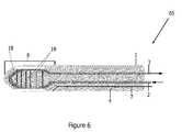
- FIGS. 3-6are side views of various embodiments of a device of the invention.
- FIG. 7is an illustrative embodiment of a product of the present invention.
- FIG. 1 and FIG. 2An external view of a device 15 in accordance with one embodiment of the present invention is shown in FIG. 1 and FIG. 2 .
- the device 15 of an embodimenttakes the form of a catheter 15 having a tube within a tube configuration, and forming the longitudinal body 15 .
- the longitudinal body 15comprises internal tubes, including a supply line 2 and a return line 3 , contained within an outer insulation tube 1 and continuously running through the length of the tubular shaft 10 of the longitudinal body 15 .
- the outer insulation tube 1 , or outer catheter sheath 1defines the size, shape, and dimensions of the longitudinal body 15 which conforms to dimensions that are capable of housing the internal lines 2 , 3 .
- the tubular shafttherefore extends from a proximal end 11 of the longitudinal body 15 to a distal end or tip 8 .
- the outer catheter sheath 1provides a unitary support structure for the flow of liquid cryogen to and from the distal end of the catheter tip 8 ; desirably, the distal end is where a freezing event is initiated.
- the liquid cryogen utilized in one embodimentmay be liquid nitrogen, though any desired liquid cryogen may be utilized and the system adjusted to accommodate for different chemistries.
- the inner supply line 2 and return line 3are maintained in the center of the outer sheath 1 by open configuration insulative spacers 13 placed throughout the catheter 15 .
- the open configurationallows for a catheter lumen 4 to be filled with gas.
- the outer catheter sheath 1is sealed to the connector 6 to create the gaseous lumen 4 .
- the tip 8in combination with the inner supply line 2 and the return line 3 come into contact with the outer sheath 1 at the distal end to develop a freezing region.
- the shaft 10 of the catheter 15is flexible, as facilitated by a deflection wire 7 that runs along the shaft 10 , the shaft of which is insulated by a temperature induced vacuum.
- the deflection wire 7is a control line that runs down the shaft 10 to the tip of the catheter 15 to allow the catheter tip 8 to be moved on an angle, in a finger-like motion to steer and direct the catheter/probe 15 to the target tissue.
- the deflection wire 7guides the device 15 and monitors environmental measures of temperature, pressure, and/or physiological conditions.
- the guide 7may integrate individual components and sensors such as an optical imaging component in connection with the guide or any number of thermocouples, pressure transducers, electrocardiogram monitors, or other electrophysiological sensors, alone or in combination.
- insulative foame.g. styrofoam, plastics, rubberized materials or other such insulative compositions
- insulative foame.g. styrofoam, plastics, rubberized materials or other such insulative compositions
- Various aspects of the inventionaccommodate a catheter tip 8 as designed to be steerable and deflectable to allow for guided targeting to the desired tissue site.
- spacers or insulative foammay be utilized to prevent internal supply and return lines from contacting the outer sheath.
- any freeze zonecan be produced as designated by the configurations of catheter tips 8 . (See FIGS. 3-6 ).
- a condensation based vacuum insulationis temperature dependent and located in the catheter 15 .
- a process of physically marking or chemically etching the surfaces 9enhances nucleation and physical vaporization deposition of saturated gas.
- the surfacemay be roughened, sprayed with any number of powder-like substances like silica, metallic particles and/or a carbon coating.
- the lumen 4 within the outer sheath 1is filled with select vapors, or non-equilibrated phase change gas 14 .
- butaneis utilized which remains in a gaseous state at about room temperature, between about 0° C.
- one embodimentmay interconnect a vacuum line of a cryosystem console with the catheter or probe 15 through a vacuum port 5 of the connector 6 as illustrated in FIGS. 1A and 2A .
- the vacuumis formed upon sealing the lumen at the connector and mechanically drawing a vacuum through vacuum port 5 .
- the vacuum portmay connect via its own vacuum system or in combination with the vacuum pump of the cryosystem.
- a dual insulative barriercan be created in the present invention by either a mechanically drawn vacuum or a spontaneously induced vacuum [via temperature inducement] (the vacuum itself creating the insulation for the internal tubes) in combination with a nucleation enhanced surface modification to enhance deposition of gas crystals onto the designated outer surfaces of the internal tubes.
- the outer walls of the internal tubesare physically or chemically etched at designated sites along the tubular shaft. A region within the distal end or tip 8 can then be configured specifically designated freeze zones.
- nucleation/sublimation in combination with a deposition processforms solid crystals along the supply line 2 and return line 3 outer walls, and spontaneously results in an evacuated space between the inner line 2 and the outer line 3 .
- the evacuated spaceacts as an insulative barrier between the outer catheter sheath and the frost encased inner lines 2 , 3 .
- Film wise deposition along an entire surface of the supply line 2 and return line 3results in crystalline film deposits of low thermal conductivity (Note:
- the ‘x’ marks in FIGS. 1A and 1Bdemonstrate the nucleation enriched supply and return tubular surfaces 9 , the tubular surfaces of which are modified by processes described herein.
- the non-solidified gas crystals 14 , non-equilibrating phase change gas particles 14are illustrated in FIG. 1B .
- Nucleated or solidified particles, as designated by “*”are depicted in FIGS. 2A , 2 B upon the modifications “x” (etching) on the surfaces 9 .
- the nucleated particles 12(marked as “*”) are formed when the gas reaches a freezing temperature.
- any pressuremay be utilized.
- pressure in the devicemay be maintained or controllably elevated or reduced.
- gasmay be maintained at atmospheric or high pressure to support the retention of the vapor state at room temperature.
- gasas either a pure component or as a mixture of various components.
- gaseous compositionsfor exemplary purposes only and not limitation, may comprise butane, carbon dioxide, iodine, camphor, and/or nitrous oxide.
- an enhanced nucleation surface 9 on inner tube/line 2 , 3 surfacesmay result where a process includes treating the walls of the inner lines 2 , 3 to match nucleating efficiency with the chemical characteristics of the gas to be deposited (e.g. marking the surfaces with impurities, utilizing silica, or other powderized material, chemically coating or etching) and thereby create a similar effect.
- Embodiments of the present inventionmanipulate the structural configurations of the tips 8 , as illustrated in FIGS. 3-6 .
- the freeze zoneis created where the internal components 2 / 3 contact the outer sheath 1 at a distal end 8 .
- FIG. 3includes a closed loop coiled supply tube 16 in contact with the outer sheath 1 to affect a cold sink.
- the supply line 2 and return line 3convene at the freezing zone of the tip in the formation of a coil 16 .
- a metallic balloon tip 17is illustrated in which cryogen is circulated in the tip and then returned.
- the supply line 2extends to a distance into the tip 8 beyond the extension of return line 3 such that cryogen pumped into the balloon-like tip 7 circulates within the sealed confines of the inflated region when the catheter is engaged for the procedure.
- the supply line 2can extend any length or distance into the tip.
- the balloon-like tipmay be composed of any flexible or rigid material including metallic, plastic, or ceramic compositions.
- the balloon-like structure within the sheathmay cause the outer sheath 1 to inflate and deflate for cryogenic procedures.
- cryogenic procedures performed within a vesselmay advantageously make use of an inflatable cryogenic element 17 at the distal end of the probe so that the outer sheath expands as the internal inflatable cryogenic element expands.
- the inflatable tipis a sealed within the distal tip 8 in connection with both an individual supply line 2 and an individual return line 3 .
- the needle-like probe 45is a longitudinal tube 45 having a distal end 8 which serves as the freezing region in connection with the tubular shaft 10 (only a portion of which is illustrated here in FIG. 4 ).
- a sealed interface 27ensures that the inflatable area can expand and contract in correspondence with the fill and removal of the cryogenic medium.
- the cryogenic mediumin one embodiment in liquid nitrogen. Any cryogen may be utilized, however, to accommodate the demands of the system and treatment measures.
- the inflatable structure, here, a metallic balloon tipis designed and configured with materials that conform to the use of liquid nitrogen. Without considering the type of cryogen utilized, the inflatable tip may rupture or create undesired effects.
- the tip of the present embodimentis designed to meet the needs of a system and device utilizing liquid nitrogen.
- the sealed interface 27may be a wall or connection component (not illustrated) which seals the freezing region 8 of the tip away from the tubular shaft 10 in a blunt-tip probe.
- the sealed interfaceallows a supply line 2 and a return line 3 to access the freezing tip, the open ends 37 of which allow cryogen to be dispersed within the sealed zone 8 .
- the sealed zoneis the balloon tip, but any size or shape of sealed zone may be utilized in different aspects of the present invention to create similar results.
- the open-ended supply linein one embodiment extends further into the sealed zone toward the distal end and beyond the open end of the return line. Any length of supply line or return line, however, may be utilized; the lengths may be designed having equal lengths or different lengths, as desired.
- FIG. 5is another embodiment of the probe tip which illustrates a closed loop tip 18 .
- the closed loop tipintegrally connects both supply line 2 and return line 3 to form a unitary structure for delivery and return of liquid cryogen to the distal end in the freezing region of the probe.
- FIG. 6illustrates a cryoprobe 65 as a closed loop tip with a finned heat exchanger 19 within the freezing zone or tip 8 .
- the heat exchangerprovides for a more efficient heat extraction from the tissue, thereby providing faster cryotreatment and greater injury/freezing to the tissue site.
- the heat exchangeris also utilized to cool the cryogen prior to return to the console, resulting in increased cryogen recovery.
- Other variations in tip designmay be any size and dimension or take the size or shape of known catheters 15 in the field. Further configurations of the cryoprobe as described infra may also accommodate other structural variations.
- the product for performing cryotherapeutic proceduresis illustrated as an elongated body 75 , about six feet in length.
- a connector 76 at a proximal end 21allows the cryoprobe to be connected with a cryogenic delivery system.
- the freezing region, or tip 18is positioned within the distal end 28 with a flexible tubular shaft 20 positioned between the ends.
- Some of the various embodiments of distal end 28have been depicted in FIGS. 3-6 , embodiments of distal ends 35 , 45 , 55 , 65 which can serve as replacements for the distal end 28 within the elongated product 75 .
- the support structure 75comprises an outer sheath (as illustrated in FIGS.
- the product 75When in use and hooked to a cryogenic delivery system, the product 75 simultaneously produces an insulative vacuum throughout the tubular shaft 20 .
- a dual insulative barrieris formed by a temperature initiated transient vacuum in combination with an enhanced nucleation deposition process along the outer surface of the internal tubes (discussed infra). The nucleation sites are therefore capable of selective placement anywhere throughout the product.
- the distal end 28is a needle-like probe end. In another embodiment, the distal end 28 takes the form of a blunt-tip probe end.
- the distal portion 28may be integral with the tubular shaft or be removably placed in connection therewith. The interconnections of proximal connector, tubular shaft, and distal probe ends thus determines whether or not the individual parts, alone or in combination, may be reused, or disposed of. Further, the length of the distal end 28 may vary according to treatment procedure and may be any size, shape and dimension to correspond to the tissue treated.
- the embodiments of the present inventionare for exemplary purposes only and not limitation.
- this devicecan be utilized for targeted thermal therapies.
- Various cryosurgical devices and procedures to apply freezing temperatures to a target tissuemay be employed for use with the medical device of the invention.
- the medical devicefurther has been developed to enable and improve the approaches used to target or ablate tissue.
- the device in the inventionmay be of any size, shape, or dimension.
- the devicemay be single use disposable or a multi-use/reusable part (and capable of being sterilized between individual patient treatments).
- the longitudinal bodyextends up to about 6-8 feet or more. Any length, however, may be utilized as designed for particular therapies and treatments. Dimensions less than 12 inches, however, may also be better suited where attached tubing, removable, detachable, or disposable parts are integrated in the design.
- the entire longitudinal bodymay incorporate the nucleation enhanced sites on any outer surface of the internal tubes or on any other designated area or specified site within the lumen of the body.
- the tubular shaftcomprises nucleation sites along the outer surfaces of the internal tubes, thereby reserving the distal end as the freeze zone for positioning with the targeted tissue.
- the inventionfacilitates other improvements in cryotherapy, and medical devices or components associated with the treatment.
- the medical device of the inventionallows for the circulation (cooling, delivery, and return) of liquid cryogen to a cryoprobe for the freezing of targeted tissue.
- the inventionfacilitates the eradication of tissue and can thereby decrease hospitalization time; further advantages reduce postoperative morbidities, shorten return to daily functions and work, and further lessen the overall treatment cost.
- the device of the inventionrepresents an approach in the development of cryosurgical devices by allowing for temperature induced transient vacuum insulation along the shaft of a cryoprobe or catheter; including insulating the shaft of a cryoprobe or catheter and delivery of cryogen in targeted thermal therapy. Furthermore, the device has been developed to couple the temperature initiated vacuum with that of a surface modification along the inner tubes to enable enhanced nucleation and deposition of the saturated gas on the surface of the inner tubes and create an additional layer of insulation. In one aspect, the device of the invention allows for the enhanced deposition on the outer surface of the inner tubes through modification of the tube surface, thereby creating an additional insulation barrier. In another aspect, the saturated gas filled lumen of the outer tube at ambient temperature may be either elevated or at atmospheric pressure.
- the embodiments of the present inventionmay be modified to take the shape of any device, container, apparatus, or vessel currently used in industry.
- cylindrical or alternative structural designsmay be utilized in the cryogenic system for improved catheter/probe access to a tissue target.
- any rearrangement of the tubes/lines in combination with the components of the above systemmay take many forms and be of any size, shape, or passageway.
- the multiple embodiments of the present inventionoffer several improvements over standard medical devices currently used in cryogenic industry.
- the improved cryogenic medical devicesremarkably enhance its utilization for the cooling, delivery and return of a liquid cryogen to a cryoprobe for the freezing of targeted tissue.
- the previously unforeseen benefitshave been realized and conveniently offer advantages for the treatment of multiple disease states.
- the improvementsenable construction of the device as designed to enable easy handling, storage, and accessibility.
- the devicemay include any unitary structure or device with the capacity to integrally incorporate any combination of such structures.
Landscapes
- Health & Medical Sciences (AREA)
- Life Sciences & Earth Sciences (AREA)
- Surgery (AREA)
- Public Health (AREA)
- Animal Behavior & Ethology (AREA)
- Engineering & Computer Science (AREA)
- Biomedical Technology (AREA)
- Heart & Thoracic Surgery (AREA)
- Veterinary Medicine (AREA)
- General Health & Medical Sciences (AREA)
- Nuclear Medicine, Radiotherapy & Molecular Imaging (AREA)
- Physics & Mathematics (AREA)
- Thermal Sciences (AREA)
- Vascular Medicine (AREA)
- Otolaryngology (AREA)
- Molecular Biology (AREA)
- Medical Informatics (AREA)
- Surgical Instruments (AREA)
- Thermotherapy And Cooling Therapy Devices (AREA)
Abstract
Description
Claims (23)
Priority Applications (7)
| Application Number | Priority Date | Filing Date | Title |
|---|---|---|---|
| US12/562,301US8439905B2 (en) | 2008-09-19 | 2009-09-18 | Nucleation enhanced surface modification to support physical vapor deposition to create a vacuum |
| EP09812404.3AEP2330995B1 (en) | 2008-09-03 | 2009-11-02 | A cryogenic system and method of use |
| PCT/US2009/062928WO2010028409A1 (en) | 2008-09-03 | 2009-11-02 | A cryogenic system and method of use |
| EP15179592.9AEP3173041B1 (en) | 2009-09-02 | 2009-11-02 | A cryogenic system |
| CA2736221ACA2736221C (en) | 2008-09-03 | 2009-11-02 | A cryogenic system and method of use |
| ES09812404.3TES2551324T3 (en) | 2008-09-03 | 2009-11-02 | A cryogenic system and method of use |
| US16/717,721US20200121498A1 (en) | 2008-09-03 | 2019-12-17 | Cryogenic System and Method of Use |
Applications Claiming Priority (2)
| Application Number | Priority Date | Filing Date | Title |
|---|---|---|---|
| US9824408P | 2008-09-19 | 2008-09-19 | |
| US12/562,301US8439905B2 (en) | 2008-09-19 | 2009-09-18 | Nucleation enhanced surface modification to support physical vapor deposition to create a vacuum |
Related Child Applications (2)
| Application Number | Title | Priority Date | Filing Date |
|---|---|---|---|
| US13/061,171ContinuationUS8784409B2 (en) | 2008-09-03 | 2009-11-02 | Cryogenic system and method of use |
| PCT/US2009/062928ContinuationWO2010028409A1 (en) | 2008-09-03 | 2009-11-02 | A cryogenic system and method of use |
Publications (2)
| Publication Number | Publication Date |
|---|---|
| US20100076421A1 US20100076421A1 (en) | 2010-03-25 |
| US8439905B2true US8439905B2 (en) | 2013-05-14 |
Family
ID=42038406
Family Applications (3)
| Application Number | Title | Priority Date | Filing Date |
|---|---|---|---|
| US12/562,301Active2031-08-18US8439905B2 (en) | 2008-09-03 | 2009-09-18 | Nucleation enhanced surface modification to support physical vapor deposition to create a vacuum |
| US15/445,968AbandonedUS20170172791A1 (en) | 2008-09-03 | 2017-02-28 | Cryogenic System and Method of Use |
| US16/717,721AbandonedUS20200121498A1 (en) | 2008-09-03 | 2019-12-17 | Cryogenic System and Method of Use |
Family Applications After (2)
| Application Number | Title | Priority Date | Filing Date |
|---|---|---|---|
| US15/445,968AbandonedUS20170172791A1 (en) | 2008-09-03 | 2017-02-28 | Cryogenic System and Method of Use |
| US16/717,721AbandonedUS20200121498A1 (en) | 2008-09-03 | 2019-12-17 | Cryogenic System and Method of Use |
Country Status (1)
| Country | Link |
|---|---|
| US (3) | US8439905B2 (en) |
Cited By (1)
| Publication number | Priority date | Publication date | Assignee | Title |
|---|---|---|---|---|
| US11771486B2 (en) | 2017-01-17 | 2023-10-03 | Corfigo, Inc. | Device for ablation of tissue surfaces and related systems and methods |
Families Citing this family (24)
| Publication number | Priority date | Publication date | Assignee | Title |
|---|---|---|---|---|
| ES2864589T3 (en)* | 2011-04-12 | 2021-10-14 | Thermedical Inc | Devices for conformal therapy in fluid-enhanced ablation |
| US9243726B2 (en) | 2012-10-03 | 2016-01-26 | Aarne H. Reid | Vacuum insulated structure with end fitting and method of making same |
| CN109846543B (en)* | 2013-09-24 | 2021-09-21 | 艾达吉欧医疗公司 | Cryoablation catheter based on intravascular near-critical fluid and related methods |
| US9463918B2 (en) | 2014-02-20 | 2016-10-11 | Aarne H. Reid | Vacuum insulated articles and methods of making same |
| US10497908B2 (en) | 2015-08-24 | 2019-12-03 | Concept Group, Llc | Sealed packages for electronic and energy storage devices |
| US10065256B2 (en) | 2015-10-30 | 2018-09-04 | Concept Group Llc | Brazing systems and methods |
| CN109154641B (en) | 2016-03-04 | 2021-09-17 | 概念集团有限责任公司 | Vacuum insulation article with reflective material enhancement |
| WO2018022610A1 (en)* | 2016-07-26 | 2018-02-01 | Csa Medical, Inc. | Apparatus to perform cryotherapy |
| EP3528729A1 (en) | 2016-10-24 | 2019-08-28 | CSA Medical, Inc. | Method&apparatus for performing cryotherapy of distal lung lesions |
| WO2018093773A1 (en) | 2016-11-15 | 2018-05-24 | Reid Aarne H | Multiply-insulated assemblies |
| CA3043915A1 (en) | 2016-11-15 | 2018-05-24 | Concept Group Llc | Enhanced vacuum-insulated articles with microporous insulation |
| US20190380761A1 (en)* | 2017-02-28 | 2019-12-19 | University Of Florida Research Foundation, Inc. | Controlling esophageal temperature during cardiac ablation |
| US11320086B2 (en) | 2017-08-25 | 2022-05-03 | Concept Group Llc | Multiple geometry and multiple material insulated components |
| WO2019083764A1 (en)* | 2017-10-27 | 2019-05-02 | St. Jude Medical, Cardiology Division, Inc. | Cryogenic ablation system |
| EP4013324B1 (en) | 2019-08-14 | 2025-09-24 | Biocompatibles UK Limited | Dual stage cryocooler |
| AU2020330099B2 (en)* | 2019-08-14 | 2024-02-01 | Biocompatibles Uk Limited | Flexible cryoprobe |
| EP3854359A1 (en)* | 2020-01-27 | 2021-07-28 | Jr. Simeon Wall | Tissue eradication methods and systems |
| US11633224B2 (en) | 2020-02-10 | 2023-04-25 | Icecure Medical Ltd. | Cryogen pump |
| US12070526B2 (en) | 2020-05-14 | 2024-08-27 | Cpsi Holdings Llc | Cryogenic disinfection system and method |
| US12426934B2 (en) | 2022-02-28 | 2025-09-30 | Icecure Medical Ltd. | Cryogen flow control |
| US20230298709A1 (en)* | 2022-03-17 | 2023-09-21 | Varian Medical Systems, Inc. | Apparatuses and methods for adaptively controlling cryoablation systems |
| US12376897B2 (en) | 2022-03-17 | 2025-08-05 | Varian Medical Systems, Inc. | Apparatuses and methods for the control and optimization of ice formation during cryoablation treatments |
| US20230381015A1 (en) | 2022-05-31 | 2023-11-30 | Icecure Medical Ltd. | Cryogenic system with multiple submerged pumps |
| US12215811B2 (en) | 2022-07-18 | 2025-02-04 | Icecure Medical Ltd. | Cryogenic system connector |
Citations (41)
| Publication number | Priority date | Publication date | Assignee | Title |
|---|---|---|---|---|
| US3858805A (en)* | 1973-10-31 | 1975-01-07 | Univ Lehigh | Ice nucleation by micas |
| US3971383A (en) | 1974-05-07 | 1976-07-27 | Erbe Elektromedizin Kg | Cryogenic surgical instrument |
| US4082096A (en) | 1973-12-10 | 1978-04-04 | Benson Jerrel W | Cryosurgical system |
| US4243619A (en)* | 1978-03-31 | 1981-01-06 | Union Carbide Corporation | Process for making film from low density ethylene hydrocarbon copolymer |
| US4831846A (en) | 1988-04-12 | 1989-05-23 | The United States Of America As Represented By The United States Department Of Energy | Low temperature cryoprobe |
| US5078713A (en)* | 1988-12-01 | 1992-01-07 | Spembly Medical Limited | Cryosurgical probe |
| US5254116A (en)* | 1991-09-06 | 1993-10-19 | Cryomedical Sciences, Inc. | Cryosurgical instrument with vent holes and method using same |
| US5400602A (en)* | 1993-07-08 | 1995-03-28 | Cryomedical Sciences, Inc. | Cryogenic transport hose |
| US5423807A (en) | 1992-04-16 | 1995-06-13 | Implemed, Inc. | Cryogenic mapping and ablation catheter |
| US5452582A (en) | 1994-07-06 | 1995-09-26 | Apd Cryogenics, Inc. | Cryo-probe |
| US5520682A (en) | 1991-09-06 | 1996-05-28 | Cryomedical Sciences, Inc. | Cryosurgical instrument with vent means and method using same |
| US5674218A (en) | 1990-09-26 | 1997-10-07 | Cryomedical Sciences, Inc. | Cryosurgical instrument and system and method of cryosurgery |
| US5733280A (en) | 1995-11-15 | 1998-03-31 | Avitall; Boaz | Cryogenic epicardial mapping and ablation |
| US5817326A (en)* | 1995-12-01 | 1998-10-06 | The Regents Of The University Of California | Processing of hydroxylapatite coatings on titanium alloy bone prostheses |
| US5869604A (en)* | 1995-11-09 | 1999-02-09 | Georgia Institute Of Technology | Crystallization and purification of polypeptides |
| US5899898A (en)* | 1997-02-27 | 1999-05-04 | Cryocath Technologies Inc. | Cryosurgical linear ablation |
| US5951546A (en) | 1994-12-13 | 1999-09-14 | Lorentzen; Torben | Electrosurgical instrument for tissue ablation, an apparatus, and a method for providing a lesion in damaged and diseased tissue from a mammal |
| US6241722B1 (en)* | 1998-06-17 | 2001-06-05 | Cryogen, Inc. | Cryogenic device, system and method of using same |
| US6468268B1 (en) | 1999-01-25 | 2002-10-22 | Cryocath Technologies Inc. | Cryogenic catheter system |
| US6468269B1 (en) | 1999-03-02 | 2002-10-22 | Nikolai Korpan | Cryogenic system, especially for performing cryosurgical surgery |
| US6485560B1 (en)* | 1999-04-28 | 2002-11-26 | The Trustees Of Princeton University | Methods of protecting concrete from freeze damage |
| US6508814B2 (en) | 1994-03-15 | 2003-01-21 | Proserfina R. Tortal | Method and apparatus for rupturing targeted cells |
| US6547784B1 (en) | 2000-06-23 | 2003-04-15 | Ethicon, Inc. | System and method for placement of a surgical instrument in a body cavity |
| US6551309B1 (en) | 2000-09-14 | 2003-04-22 | Cryoflex, Inc. | Dual action cryoprobe and methods of using the same |
| US6648879B2 (en) | 1999-02-24 | 2003-11-18 | Cryovascular Systems, Inc. | Safety cryotherapy catheter |
| US20040215295A1 (en) | 2003-01-15 | 2004-10-28 | Mediphysics Llp | Cryotherapy system |
| US6875209B2 (en) | 2001-09-27 | 2005-04-05 | Galil Medical Ltd. | Cryoplasty apparatus and method |
| US20060079867A1 (en) | 2003-04-03 | 2006-04-13 | Nir Berzak | Apparatus and method for accurately delimited cryoablation |
| US7156840B2 (en) | 2004-06-29 | 2007-01-02 | Cryocor, Inc. | Pressure monitor for cryoablation catheter |
| US7163535B2 (en) | 2004-06-30 | 2007-01-16 | Cryocor, Inc. | System for detecting leaks and occlusions in a cryoablation catheter |
| US20070244474A1 (en) | 2006-04-18 | 2007-10-18 | Sanarus Medical, Inc. | Cryosurgical system |
| US20070277550A1 (en) | 2000-08-09 | 2007-12-06 | Cryocor, Inc. | Refrigeration source for a cryoablation catheter |
| US7306589B2 (en) | 2003-04-24 | 2007-12-11 | Boston Scientific Scimed, Inc. | Therapeutic apparatus having insulated region at the insertion area |
| US20080009845A1 (en) | 2003-06-25 | 2008-01-10 | Endocare, Inc. | Cryosurgical probe with adjustable sliding apparatus |
| US20080027422A1 (en) | 2006-07-25 | 2008-01-31 | Ams Research Corporation | Closed-Loop Cryosurgical System and Cryoprobe |
| US20080147056A1 (en) | 2006-07-14 | 2008-06-19 | Micrablate | Energy delivery systems and uses thereof |
| US20080173028A1 (en) | 2003-01-15 | 2008-07-24 | Cryodynamics, Llc | Methods and systems for cryogenic cooling |
| US20080255551A1 (en) | 2007-04-16 | 2008-10-16 | Sanarus Medical, Inc. | Cryosurgical System with Low Pressure Cryogenic Fluid Supply |
| US20080300584A1 (en) | 2007-06-01 | 2008-12-04 | Lentz David J | Cryoablation segment for creating linear lesions |
| US20090281533A1 (en) | 2008-05-12 | 2009-11-12 | Boston Scientific Scimed, Inc. | Apparatus and method for chilling cryo-ablation coolant and resulting cryo-ablation system |
| US20100241112A1 (en) | 2009-03-23 | 2010-09-23 | Boston Scientific Scimed, Inc. | Systems apparatus and methods for distributing coolant within a cryo-ablation device |
Family Cites Families (5)
| Publication number | Priority date | Publication date | Assignee | Title |
|---|---|---|---|---|
| KR0144165B1 (en)* | 1995-05-12 | 1998-07-01 | 문정환 | Improved Manufacturing Method of Inverse Tee (T) Transistor |
| US7006874B2 (en)* | 1996-01-05 | 2006-02-28 | Thermage, Inc. | Treatment apparatus with electromagnetic energy delivery device and non-volatile memory |
| US6287326B1 (en)* | 1999-08-02 | 2001-09-11 | Alsius Corporation | Catheter with coiled multi-lumen heat transfer extension |
| US20050026167A1 (en)* | 2001-06-11 | 2005-02-03 | Mark Birch-Machin | Complete mitochondrial genome sequences as a diagnostic tool for the health sciences |
| US7294400B2 (en)* | 2003-03-17 | 2007-11-13 | Hewlett-Packard Development Company, L.P. | Flexible barrier film structure |
- 2009
- 2009-09-18USUS12/562,301patent/US8439905B2/enactiveActive
- 2017
- 2017-02-28USUS15/445,968patent/US20170172791A1/ennot_activeAbandoned
- 2019
- 2019-12-17USUS16/717,721patent/US20200121498A1/ennot_activeAbandoned
Patent Citations (46)
| Publication number | Priority date | Publication date | Assignee | Title |
|---|---|---|---|---|
| US3858805A (en)* | 1973-10-31 | 1975-01-07 | Univ Lehigh | Ice nucleation by micas |
| US4082096A (en) | 1973-12-10 | 1978-04-04 | Benson Jerrel W | Cryosurgical system |
| US3971383A (en) | 1974-05-07 | 1976-07-27 | Erbe Elektromedizin Kg | Cryogenic surgical instrument |
| US4243619A (en)* | 1978-03-31 | 1981-01-06 | Union Carbide Corporation | Process for making film from low density ethylene hydrocarbon copolymer |
| US4831846A (en) | 1988-04-12 | 1989-05-23 | The United States Of America As Represented By The United States Department Of Energy | Low temperature cryoprobe |
| US5078713A (en)* | 1988-12-01 | 1992-01-07 | Spembly Medical Limited | Cryosurgical probe |
| US5674218A (en) | 1990-09-26 | 1997-10-07 | Cryomedical Sciences, Inc. | Cryosurgical instrument and system and method of cryosurgery |
| US5254116A (en)* | 1991-09-06 | 1993-10-19 | Cryomedical Sciences, Inc. | Cryosurgical instrument with vent holes and method using same |
| US5520682A (en) | 1991-09-06 | 1996-05-28 | Cryomedical Sciences, Inc. | Cryosurgical instrument with vent means and method using same |
| US5423807A (en) | 1992-04-16 | 1995-06-13 | Implemed, Inc. | Cryogenic mapping and ablation catheter |
| US5400602A (en)* | 1993-07-08 | 1995-03-28 | Cryomedical Sciences, Inc. | Cryogenic transport hose |
| US6508814B2 (en) | 1994-03-15 | 2003-01-21 | Proserfina R. Tortal | Method and apparatus for rupturing targeted cells |
| US5452582A (en) | 1994-07-06 | 1995-09-26 | Apd Cryogenics, Inc. | Cryo-probe |
| US5951546A (en) | 1994-12-13 | 1999-09-14 | Lorentzen; Torben | Electrosurgical instrument for tissue ablation, an apparatus, and a method for providing a lesion in damaged and diseased tissue from a mammal |
| US5869604A (en)* | 1995-11-09 | 1999-02-09 | Georgia Institute Of Technology | Crystallization and purification of polypeptides |
| US5733280A (en) | 1995-11-15 | 1998-03-31 | Avitall; Boaz | Cryogenic epicardial mapping and ablation |
| US5817326A (en)* | 1995-12-01 | 1998-10-06 | The Regents Of The University Of California | Processing of hydroxylapatite coatings on titanium alloy bone prostheses |
| US5899898A (en)* | 1997-02-27 | 1999-05-04 | Cryocath Technologies Inc. | Cryosurgical linear ablation |
| US6241722B1 (en)* | 1998-06-17 | 2001-06-05 | Cryogen, Inc. | Cryogenic device, system and method of using same |
| US6468268B1 (en) | 1999-01-25 | 2002-10-22 | Cryocath Technologies Inc. | Cryogenic catheter system |
| US6887234B2 (en) | 1999-01-25 | 2005-05-03 | Cryocath Technologies Inc. | Cryogenic catheter system |
| US7404816B2 (en) | 1999-01-25 | 2008-07-29 | Cryocath Technologies Inc. | Leak detection system |
| US6648879B2 (en) | 1999-02-24 | 2003-11-18 | Cryovascular Systems, Inc. | Safety cryotherapy catheter |
| US6468269B1 (en) | 1999-03-02 | 2002-10-22 | Nikolai Korpan | Cryogenic system, especially for performing cryosurgical surgery |
| US6485560B1 (en)* | 1999-04-28 | 2002-11-26 | The Trustees Of Princeton University | Methods of protecting concrete from freeze damage |
| US6547784B1 (en) | 2000-06-23 | 2003-04-15 | Ethicon, Inc. | System and method for placement of a surgical instrument in a body cavity |
| US20090318913A1 (en) | 2000-08-09 | 2009-12-24 | Hong Li | Refrigeration source for a cryoablation catheter |
| US20070277550A1 (en) | 2000-08-09 | 2007-12-06 | Cryocor, Inc. | Refrigeration source for a cryoablation catheter |
| US6551309B1 (en) | 2000-09-14 | 2003-04-22 | Cryoflex, Inc. | Dual action cryoprobe and methods of using the same |
| US6875209B2 (en) | 2001-09-27 | 2005-04-05 | Galil Medical Ltd. | Cryoplasty apparatus and method |
| US20080173028A1 (en) | 2003-01-15 | 2008-07-24 | Cryodynamics, Llc | Methods and systems for cryogenic cooling |
| US20040215295A1 (en) | 2003-01-15 | 2004-10-28 | Mediphysics Llp | Cryotherapy system |
| US20060235375A1 (en) | 2003-01-15 | 2006-10-19 | Cryodynamics, Llc | Cryotherapy system |
| US20060079867A1 (en) | 2003-04-03 | 2006-04-13 | Nir Berzak | Apparatus and method for accurately delimited cryoablation |
| US7306589B2 (en) | 2003-04-24 | 2007-12-11 | Boston Scientific Scimed, Inc. | Therapeutic apparatus having insulated region at the insertion area |
| US7306590B2 (en) | 2003-04-24 | 2007-12-11 | Boston Scientific Scimed, Inc. | Therapeutic apparatus having insulated region at the insertion area |
| US20080009845A1 (en) | 2003-06-25 | 2008-01-10 | Endocare, Inc. | Cryosurgical probe with adjustable sliding apparatus |
| US7156840B2 (en) | 2004-06-29 | 2007-01-02 | Cryocor, Inc. | Pressure monitor for cryoablation catheter |
| US7163535B2 (en) | 2004-06-30 | 2007-01-16 | Cryocor, Inc. | System for detecting leaks and occlusions in a cryoablation catheter |
| US20070244474A1 (en) | 2006-04-18 | 2007-10-18 | Sanarus Medical, Inc. | Cryosurgical system |
| US20080147056A1 (en) | 2006-07-14 | 2008-06-19 | Micrablate | Energy delivery systems and uses thereof |
| US20080027422A1 (en) | 2006-07-25 | 2008-01-31 | Ams Research Corporation | Closed-Loop Cryosurgical System and Cryoprobe |
| US20080255551A1 (en) | 2007-04-16 | 2008-10-16 | Sanarus Medical, Inc. | Cryosurgical System with Low Pressure Cryogenic Fluid Supply |
| US20080300584A1 (en) | 2007-06-01 | 2008-12-04 | Lentz David J | Cryoablation segment for creating linear lesions |
| US20090281533A1 (en) | 2008-05-12 | 2009-11-12 | Boston Scientific Scimed, Inc. | Apparatus and method for chilling cryo-ablation coolant and resulting cryo-ablation system |
| US20100241112A1 (en) | 2009-03-23 | 2010-09-23 | Boston Scientific Scimed, Inc. | Systems apparatus and methods for distributing coolant within a cryo-ablation device |
Non-Patent Citations (1)
| Title |
|---|
| Fladerer et al. "Homogenous nucleation and droplet growth in supersaturated argon vapor: The cryogenic nucleation pulse chamber," Journal of Chemical Physics (2006), vol. 124. 2006 American Institute of Physics. USA. |
Cited By (1)
| Publication number | Priority date | Publication date | Assignee | Title |
|---|---|---|---|---|
| US11771486B2 (en) | 2017-01-17 | 2023-10-03 | Corfigo, Inc. | Device for ablation of tissue surfaces and related systems and methods |
Also Published As
| Publication number | Publication date |
|---|---|
| US20200121498A1 (en) | 2020-04-23 |
| US20100076421A1 (en) | 2010-03-25 |
| US20170172791A1 (en) | 2017-06-22 |
Similar Documents
| Publication | Publication Date | Title |
|---|---|---|
| US8439905B2 (en) | Nucleation enhanced surface modification to support physical vapor deposition to create a vacuum | |
| CA2736221C (en) | A cryogenic system and method of use | |
| US9974592B2 (en) | Cryogenic medical system | |
| US9408655B2 (en) | Cryoablation apparatus with enhanced heat exchange area and related method | |
| JP6413131B2 (en) | Catheter for plaque stabilization | |
| US20180071007A1 (en) | Catheter with jet impingement cooled thermoelectric module | |
| US20150257810A1 (en) | Flexible cryogenic probe tip | |
| EP0680284A1 (en) | Cryogenic catheter | |
| JP2009545365A (en) | Cryogenic probe for treating enlarged parts of tissue | |
| EP3173041B1 (en) | A cryogenic system | |
| WO2007073493A2 (en) | Cryoprobe with exhaust heater |
Legal Events
| Date | Code | Title | Description |
|---|---|---|---|
| AS | Assignment | Owner name:CPSI HOLDINGS LLC, NEW YORK Free format text:ASSIGNMENT OF ASSIGNORS INTEREST;ASSIGNORS:BAUST, JOHN M;ROBILOTTO, ANTHONY;SNYDER, KRISTI K.;AND OTHERS;REEL/FRAME:027154/0778 Effective date:20111031 | |
| AS | Assignment | Owner name:CPSI HOLDINGS LLC, NEW YORK Free format text:CORRECTIVE ASSIGNMENT TO CORRECT THE (REMOVAL) OF AN ASSIGNOR AND CORRECT "CORRESPONDENT NAME" PREVIOUSLY RECORDED ON REEL 027154 FRAME 0778. ASSIGNOR(S) HEREBY CONFIRMS THE ASSIGNMENT;ASSIGNORS:BAUST, JOHN M.;CHEEKS, ROY E.;BAUST, JOHN G.;AND OTHERS;REEL/FRAME:027290/0372 Effective date:20111031 | |
| AS | Assignment | Owner name:ENDO PHARMACEUTICALS INC., PENNSYLVANIA Free format text:ASSIGNMENT OF ASSIGNORS INTEREST;ASSIGNOR:CPSI HOLDINGS LLC;REEL/FRAME:027794/0791 Effective date:20120118 | |
| STCF | Information on status: patent grant | Free format text:PATENTED CASE | |
| AS | Assignment | Owner name:ENDOCARE, INC., TEXAS Free format text:ASSIGNMENT OF ASSIGNORS INTEREST;ASSIGNOR:ENDO PHARMACEUTICALS INC.;REEL/FRAME:030690/0015 Effective date:20130621 | |
| AS | Assignment | Owner name:ENDOCARE, INC., TEXAS Free format text:ASSIGNMENT OF ASSIGNORS INTEREST;ASSIGNOR:ENDO PHARMACEUTICALS INC.;REEL/FRAME:031122/0761 Effective date:20130620 | |
| AS | Assignment | Owner name:REGIONS BANK, TENNESSEE Free format text:SECURITY AGREEMENT;ASSIGNOR:ENDOCARE, INC.;REEL/FRAME:032372/0077 Effective date:20140203 | |
| AS | Assignment | Owner name:MIDCAP FINANCIAL TRUST, AS ADMINISTRATIVE AGENT, MARYLAND Free format text:SECURITY INTEREST;ASSIGNORS:HEALTHTRONICS, INC.;ENDOCARE, INC.;REEL/FRAME:038063/0201 Effective date:20160308 Owner name:MIDCAP FINANCIAL TRUST, AS ADMINISTRATIVE AGENT, M Free format text:SECURITY INTEREST;ASSIGNORS:HEALTHTRONICS, INC.;ENDOCARE, INC.;REEL/FRAME:038063/0201 Effective date:20160308 | |
| FPAY | Fee payment | Year of fee payment:4 | |
| AS | Assignment | Owner name:ENDOCARE, INC., TEXAS Free format text:RELEASE BY SECURED PARTY;ASSIGNOR:MIDCAP FINANCIAL TRUST, AS ADMINISTRATIVE AGENT;REEL/FRAME:046429/0787 Effective date:20180625 | |
| AS | Assignment | Owner name:HEALTHTRONICS, INC., TEXAS Free format text:RELEASE BY SECURED PARTY;ASSIGNOR:REGIONS BANK;REEL/FRAME:046500/0151 Effective date:20160308 Owner name:ENDOCARE, INC., TEXAS Free format text:RELEASE BY SECURED PARTY;ASSIGNOR:REGIONS BANK;REEL/FRAME:046500/0151 Effective date:20160308 | |
| MAFP | Maintenance fee payment | Free format text:PAYMENT OF MAINTENANCE FEE, 8TH YEAR, LARGE ENTITY (ORIGINAL EVENT CODE: M1552); ENTITY STATUS OF PATENT OWNER: LARGE ENTITY Year of fee payment:8 | |
| AS | Assignment | Owner name:VARIAN MEDICAL SYSTEMS, INC., CALIFORNIA Free format text:ASSIGNMENT OF ASSIGNORS INTEREST;ASSIGNOR:ENDOCARE;REEL/FRAME:055740/0029 Effective date:20210308 | |
| MAFP | Maintenance fee payment | Free format text:PAYMENT OF MAINTENANCE FEE, 12TH YEAR, LARGE ENTITY (ORIGINAL EVENT CODE: M1553); ENTITY STATUS OF PATENT OWNER: LARGE ENTITY Year of fee payment:12 |