US8439878B2 - Rheolytic thrombectomy catheter with self-inflating proximal balloon with drug infusion capabilities - Google Patents
Rheolytic thrombectomy catheter with self-inflating proximal balloon with drug infusion capabilitiesDownload PDFInfo
- Publication number
- US8439878B2 US8439878B2US12/338,376US33837608AUS8439878B2US 8439878 B2US8439878 B2US 8439878B2US 33837608 AUS33837608 AUS 33837608AUS 8439878 B2US8439878 B2US 8439878B2
- Authority
- US
- United States
- Prior art keywords
- self
- fluid
- catheter
- balloon
- inflating balloon
- Prior art date
- Legal status (The legal status is an assumption and is not a legal conclusion. Google has not performed a legal analysis and makes no representation as to the accuracy of the status listed.)
- Expired - Fee Related
Links
Images


Classifications
- A—HUMAN NECESSITIES
- A61—MEDICAL OR VETERINARY SCIENCE; HYGIENE
- A61B—DIAGNOSIS; SURGERY; IDENTIFICATION
- A61B17/00—Surgical instruments, devices or methods
- A61B17/32—Surgical cutting instruments
- A61B17/3203—Fluid jet cutting instruments
- A61B17/32037—Fluid jet cutting instruments for removing obstructions from inner organs or blood vessels, e.g. for atherectomy
- A—HUMAN NECESSITIES
- A61—MEDICAL OR VETERINARY SCIENCE; HYGIENE
- A61B—DIAGNOSIS; SURGERY; IDENTIFICATION
- A61B17/00—Surgical instruments, devices or methods
- A61B17/22—Implements for squeezing-off ulcers or the like on inner organs of the body; Implements for scraping-out cavities of body organs, e.g. bones; for invasive removal or destruction of calculus using mechanical vibrations; for removing obstructions in blood vessels, not otherwise provided for
- A61B2017/22051—Implements for squeezing-off ulcers or the like on inner organs of the body; Implements for scraping-out cavities of body organs, e.g. bones; for invasive removal or destruction of calculus using mechanical vibrations; for removing obstructions in blood vessels, not otherwise provided for with an inflatable part, e.g. balloon, for positioning, blocking, or immobilisation
- A61B2017/22062—Implements for squeezing-off ulcers or the like on inner organs of the body; Implements for scraping-out cavities of body organs, e.g. bones; for invasive removal or destruction of calculus using mechanical vibrations; for removing obstructions in blood vessels, not otherwise provided for with an inflatable part, e.g. balloon, for positioning, blocking, or immobilisation to be filled with liquid
- A—HUMAN NECESSITIES
- A61—MEDICAL OR VETERINARY SCIENCE; HYGIENE
- A61B—DIAGNOSIS; SURGERY; IDENTIFICATION
- A61B17/00—Surgical instruments, devices or methods
- A61B17/22—Implements for squeezing-off ulcers or the like on inner organs of the body; Implements for scraping-out cavities of body organs, e.g. bones; for invasive removal or destruction of calculus using mechanical vibrations; for removing obstructions in blood vessels, not otherwise provided for
- A61B2017/22051—Implements for squeezing-off ulcers or the like on inner organs of the body; Implements for scraping-out cavities of body organs, e.g. bones; for invasive removal or destruction of calculus using mechanical vibrations; for removing obstructions in blood vessels, not otherwise provided for with an inflatable part, e.g. balloon, for positioning, blocking, or immobilisation
- A61B2017/22065—Functions of balloons
Definitions
- the present disclosurerelates to a thrombectomy catheter, but more specifically relates to a rheolytic thrombectomy catheter with a self-inflating proximal balloon having drug infusion capabilities and, for purposes of brevity, is alternately referred to herein as a rheolytic thrombectomy catheter.
- a rheolytic thrombectomy catheterwith a self-inflating proximal balloon having drug infusion capabilities and, for purposes of brevity, is alternately referred to herein as a rheolytic thrombectomy catheter.
- the terms used hereinare not intended to be limited to any particular narrow interpretation unless clearly stated otherwise in this document.
- Prior art and its comparison to the devices of the present disclosureare partially set forth herein.
- Flow cessation of prior art devices to minimize hemolysis and for other reasonshas been accomplished via a balloon on a proximally placed guide catheter or by way of proprietary occlusion guidewire technology, such as, but not limited to, the use of balloons on guidewires.
- prior art cross stream jet catheter designshave been described in prior patents by the present inventors or assignees.
- Such prior art cross stream jet catheter designsuse cross stream jets flowing between outflow orifices and inflow orifices located on an exhaust tube to impinge, macerate and carry thrombus debris away from a thrombus site and through the exhaust tube.
- outflow orificesare positioned on the periphery of a self-inflated balloon to provide significantly more effective thrombus removal.
- a peripheral cross stream jet thrombectomy catheter exhaust tubemay have the diameter of 2 mm (6 Fr) and may be treating an 8 mm blood vessel.
- Cross stream jets flowing outwardly from the side outflow orificesare used to liberate debris such that the thrombus may be evacuated by the inflow orifices.
- these side exhaust jetswould typically travel outwardly at an average of 3 mm to impinge and scrub thrombus deposits on a vessel wall.
- the outwardly directed side outflow cross stream jetscould travel up to 6 mm to impinge and scrub thrombus on a vessel wall.
- the side outflow orificesare typically less than 0.66 mm in diameter and as a result the cross stream jet may travel almost 10 diameters to impinge the vessel wall.
- the surrounding fluidslows the cross stream jet, hence, the ability to remove debris is diminished.
- the self-inflating balloon size and catheterare selected by the physician to match the treated vessel size in order that the balloon will always inflate to attempt to be in direct contact with the thrombus.
- the cross stream jetswill travel a very short distance (i.e., less than 10 diameters) substantially unimpeded by surrounding fluids to impinge the thrombus with maximum velocity.
- inflation of the self-inflating balloonensures centering of the device so that the vessel is treated equally in all circumferential directions. This design enables a more effective and greater removal of tougher and more organized thrombus. Furthermore, it enables a greater and more uniform delivery of drugs into this tougher mural thrombus.
- Vessel safetyis improved and enhanced by use of devices of the present disclosure.
- vessel damageis primarily inflicted when the vessel wall is sucked in by the negative pressures at the inflow orifices to the point that the internal high velocity jet streams can damage the vessel wall.
- merely moving the catheter while the inflow orifices have been sucked onto the vessel wallis a likely mechanism for vessel damage from cross stream catheters.
- Vessel damageincreases with the size of the inflow orifices and with the proximity of the high velocity fluid jet stream origin to the inlet orifice.
- an inlet gapinlet orifice
- an inlet gapis positionally located away from the vessel wall by the centering action of the self-inflating balloon.
- the general purpose of the present disclosureis to provide a rheolytic thrombectomy catheter sold under the trademark AngioJet®, to elegantly stop and/or impede blood flow in a vessel while simultaneously increasing the efficacy of thrombus removal.
- Flow cessationoptimizes the effectiveness of thrombectomies, embolization containment, and procedures involving drug infusion, as well as minimizing hemolysis.
- Other issues addressed by the use of devices of the present disclosurerelate to catheter centering, thrombus and/or vessel dilation or a modified embolectomy.
- the main structure and feature of devices of the present disclosureinvolves the use of a proximally placed self-inflating balloon integral to and formed from a thin wall section of the exhaust tube of the rheolytic thrombectomy catheter which is inflatingly deployed using the back pressure created by the operation of the high velocity fluid jet streams used in a thrombectomy catheter, such as an AngioJet® catheter.
- the self-inflating balloonhas a plurality of outflow orifices located about its peripheral circumference. Inflation of the balloon places the outflow orifices in close proximity to the thrombus buildup on a vessel wall.
- High velocity fluid jet streams emitted from an emanatorexit these outflow orifices as uniformly distributed cross stream jets and return through an inflow gap, substantially a large inflow orifice, the function of which is closely related to that of multiple inflow orifices.
- the deviceis a rheolytic enhanced thrombectomy catheter and can be used for removal of thrombus in coronary arteries, peripheral arteries or veins, neurological arteries or veins, or arterial venous conduits.
- the expanded balloon with peripheral circumference outflow orificeswill be more efficacious in removing more organized clots.
- the blockage of blood flow by the inflated balloonalso minimizes hemolysis. Hemolysis formed from a stagnant blood field is dramatically less than that of a flowing blood field.
- the self-inflating balloon of the present disclosurecan also be used to dilate a vascular obstruction or narrowing.
- the present disclosuredescribes the addition of a self-inflating balloon with outflow orifices or perforations to any of the AngioJet® catheter models.
- the self-inflating balloonis proximally located with respect to a high velocity fluid jet stream emanator.
- the self-inflating balloonincludes a plurality of outflow orifices about its peripheral circumference so that when the self-inflating balloon is inflated, the fluid outflow in the form of cross stream jets is closely and intimately directed against the thrombus.
- the devices of the present disclosureprovide a cross stream rheolytic thrombectomy catheter where the outflow orifices are in close or intimate proximity to the vessel wall and/or thrombus. This arrangement minimizes profile, minimizes the number of components and design complexity, minimizes manufacturing costs, and is very easy to use since the self-inflating balloon is deployed automatically when the rheolytic thrombectomy catheter is activated.
- AngioJet® cathetersremove debris more effectively in a stagnant flow
- this devicehas several applications. It could be used with a filter to more effectively remove debris from within and around the filter.
- bench testinghas shown that devices of the present disclosure are substantially more efficacious at clot removal than conventional AngioJet® catheters due to a cross stream jet configuration featuring a large inflow gap (inlet orifice). Cessation of flow and the large “pocket” the self-inflating balloon creates can ultimately increase the recirculated flow rate.
- Devices of the present disclosurecan be used just to increase the amount of debris/thrombus removed from a particular vessel length. With this in mind, it should also minimize any distal or proximal embolization.
- the outflow orifices in the self-inflating ballooncan drive the drugs deeper into the thrombus or even treat or lavage a vessel wall.
- the self-inflating ballooncould also be used for centering or positioning the catheter in a vessel to minimize vessel damage as described above.
- the inlet orifice structure, herein referred to as an inflow gap, for the rheolytic thrombectomy catheteris enlarged to enable maceration of larger and tougher embolic debris.
- the self-inflating ballooncould slightly dilate an occluded section, an obstruction, or a narrowed area due to the pressurized outwardly directed self-inflating balloon structure, thereby providing automatic angioplasty along with debris removal. Finally, the self-inflating balloon could be used to break up clots as it is moved through a blocked vessel, thereby performing a modified embolectomy.
- a rheolytic thrombectomy catheterincluding a manifold, a catheter tube connected to and extending distally from the manifold, a distally located tapered flexible tip spaced distally from the distal end of the catheter tube to form an inflow gap therebetween, a tubular shaped emanator secured at the proximal end of the tapered flexible tip by the use of a marker band, a distally located thin section of the catheter tube comprising a self-inflating balloon having a plurality of outflow orifices about the peripheral circumference thereof, marker bands secured over and about the catheter tube on each end of the self-inflating balloon, and a high pressure tube extending through portions of the manifold, through the catheter tube and self-inflating balloon, and through marker bands and extending further across the inflow gap to communicatingly terminate within the emanator.
- rheolytic thrombectomy catheterincorporate and exemplify many of the features and teachings and include enhancements thereof of a rheolytic thrombectomy catheter sold under the trademark AngioJet®.
- One significant aspect and feature of devices of the present disclosureis a self-inflating proximal balloon with outflow orifices, which is created from the exhaust tube itself.
- One significant aspect and feature of devices of the present disclosureis a self-inflating proximal balloon with outflow orifices, which balloon is deployed by the back pressure created during operation of devices of the present disclosure.
- One significant aspect and feature of devices of the present disclosureis a self-inflating proximal balloon with outflow orifices, which balloon is fixed and positioned between two marker bands with an underlying stabilizing saddle or by another suitable means.
- One significant aspect and feature of devices of the present disclosureis a self-inflating proximal balloon with outflow orifices, which balloon is used for the purpose of impeding fluid flow in a blood vessel or other conduit.
- One significant aspect and feature of devices of the present disclosureis a self-inflating proximal balloon with orifices, which balloon is used for the purpose of cessation of fluid flow in a blood vessel or other conduit in order to maximize the effect of a thrombectomy catheter in terms of debris or tissue removal.
- Another significant aspect and feature of devices of the present disclosureis a self-inflating proximal balloon which is used for the purpose of cessation of fluid flow in a blood vessel or other conduit in order to maximize the effect of a thrombectomy catheter in terms of debris or tissue removal from a distal protection filter wire or a balloon.
- One significant aspect and feature of devices of the present disclosureis a self-inflating proximal balloon used for the purpose of centering the catheter.
- One significant aspect and feature of devices of the present disclosureis a self-inflating proximal balloon used for the purpose of a modified embolectomy.
- One significant aspect and feature of devices of the present disclosureis a self-inflating proximal balloon used for the purpose of dilating a vessel or an occlusion.
- One significant aspect and feature of devices of the present disclosureis a self-inflating proximal balloon used for the purpose of minimizing hemolysis.
- One significant aspect and feature of devices of the present disclosureis a self-inflating proximal balloon used for the purpose of infusing drugs on a vessel wall or into a thrombus.
- One significant aspect and feature of devices of the present disclosureis a self-inflating proximal balloon with outflow orifices used with an inflow gap for removing debris.
- One significant aspect and feature of devices of the present disclosureis a self-inflating proximal balloon with outflow orifices used with one or more inflow orifices for removing debris.
- Another significant aspect and feature of devices of the present disclosureis a self-inflating proximal balloon with outflow orifices used with an inflow gap or one or more inflow orifices for removing debris and used with additional radially directed spray jets emanating from a jet body loop.
- Still another significant aspect and feature of devices of the present disclosureis a self-inflating proximal balloon having a diameter which could range from 2-20 mm.
- Still another significant aspect and feature of devices of the present disclosureis a self-inflating proximal balloon which could range from 2-200 mm in length.
- Still another significant aspect and feature of devices of the present disclosureis a self-inflating proximal balloon which could be compliant, semi-compliant, or noncompliant in nature.
- Still another significant aspect and feature of devices of the present disclosureis a self-inflating proximal balloon having an internal operating pressure up to 20 ATM.
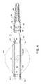
- FIG. 1is a plan view of the visible components of a rheolytic thrombectomy catheter with a self-inflating proximal balloon having drug infusion capabilities;
- FIG. 2is an isometric exploded and segmented view of FIG. 1 showing the rheolytic thrombectomy catheter having an inflow gap;
- FIG. 3is an assembled view in partial cross section of the components of the manifold shown in FIG. 2 and the closely associated components and features thereof including a guidewire;
- FIG. 4is a cross section view of the distal end of the rheolytic thrombectomy catheter
- FIG. 5is an isometric view of a fluid jet emanator having rearwardly aligned jet orifices shown connected to and in communication with a high pressure tube;
- FIG. 6illustrates the rheolytic thrombectomy catheter connected to ancillary devices
- FIG. 7is a side view in partial cross section of the distal portion of the rheolytic thrombectomy catheter
- FIG. 8is a first alternative embodiment similar to FIG. 2 illustrating a rheolytic thrombectomy catheter having a single inflow orifice;
- FIG. 9is an illustration similar to FIG. 4 showing the distal end of the rheolytic thrombectomy catheter and the arrangement of the inflow orifice in relation to the self-inflating balloon;
- FIG. 10is a second alternative embodiment similar to FIG. 8 illustrating a rheolytic thrombectomy catheter which can also emanate radially directed jets from the distal end thereof;
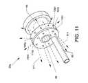
- FIG. 11is an illustration similar to FIG. 5 showing a fluid jet emanator having rearwardly aligned and radially aligned jet orifices shown connected to and in communication with a high pressure tube;
- FIG. 12is an illustration similar to FIG. 9 showing the distal end of a rheolytic thrombectomy catheter and the arrangement of the inflow orifices and the arrangement of the rearwardly and radially aligned jet orifices in relation to the self-inflating balloon; and,
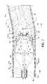
- FIG. 13is an illustration similar to FIG. 7 showing the performance of the method and use of the second alternative embodiment.
- FIG. 1is a plan view of the visible components of a rheolytic thrombectomy catheter 10 .
- the deviceincludes a one-piece manifold 12 having multiple structures extending therefrom or attached thereto, and also includes a flexible catheter tube 14 and other components associated therewith as described herein.
- the visible portion of one-piece manifold 12includes a central tubular body 16 , a threaded exhaust branch 18 , and a high pressure connection branch 20 extending angularly from central tubular body 16 , a partially shown cavity body 22 extending proximally from central tubular body 16 and a threaded connection port 24 extending distally from central tubular body 16 .
- catheter tube 14The proximal end of catheter tube 14 is secured to manifold 12 by the use of a Luer fitting 26 accommodated by threaded connection port 24 .
- the proximal end of catheter tube 14extends through a strain relief tube 28 and through Luer fitting 26 to communicate with manifold 12 .
- a hemostasis nut 30aligned with and threadingly engaged with the proximal region of cavity body 22 .
- a threaded high pressure connection port 32is secured to high pressure connection branch 20 by a Luer connector 34 .
- An introducer 36is also shown.
- Catheter tube 14extends distally to spacingly terminate a short distance from a tapered flexible tip 38 and a fluid jet emanator 52 , not shown in FIG. 1 but shown in FIGS. 4 and 5 , to provide an annular inflow gap 40 .
- a distal section of catheter tube 14includes a self-inflating balloon 42 (shown inflated by dashed lines 42 a ) proximal to inflow gap 40 .
- a plurality of outflow orifices 44 a - 44 nwhich can be arranged in various patterns is distributed about the central outer circumference of self-inflating balloon 42 for the disbursement of cross stream jets therefrom when the balloon is inflated.
- Catheter tube 14functions as an exhaust tube for the evacuation of macerated effluence from the site of a thrombus or lesion.
- catheter tube 14includes a hydrophilic coating to enhance deliverability along the vasculature or other structure.
- Catheter tube 14is made from a flexible plastic material or another suitable flexible material.
- FIG. 2is an isometric exploded and segmented view of rheolytic thrombectomy catheter 10 and FIG. 3 is an assembled view, in partial cross section, of the components of manifold 12 and closely associated components and features thereof.
- a collection of assembled components including a high pressure tube 50 and a fluid jet emanator 52deliver a high pressure saline or other suitable fluid to the distal portion of catheter tube 14 for creation of high velocity jet streams which are directed proximally from fluid jet emanator 52 and which flow as exterior cross stream jets from the plurality of outflow orifices 44 a - 44 n located at the peripheral circumference of self-inflating balloon 42 and return into inflow gap 40 , as later described in detail.
- High pressure tube 50preferably of flexible stainless steel or other suitable material, passes through and is generally distal to strain relief tube 28 and extends along a greater portion of and within a lumen of catheter tube 14 to terminate at fluid jet emanator 52 .
- the distal end of high pressure tube 50including fluid jet emanator 52 , is also shown in greater detail in FIGS. 4 and 5 .
- Manifold 12includes connected and communicating passageways and cavities ( FIG. 3 ) including a high pressure connection branch passageway 54 , an exhaust branch passageway 56 , a tapered central passageway 58 extending from and through threaded connection port 24 and through central tubular body 16 to and communicating with a multiple radius cavity 60 , which preferably is cylindrical and located central to cavity body 22 .
- External threads 62are located about the proximal portion of cavity body 22 at the proximal region of manifold 12 for accommodation of internal threads 64 of hemostasis nut 30 .
- the devices of the present disclosurebenefit from the use of a flexible self-sealing hemostasis valve 66 , and the use of a washer 68 which is located distal to self-sealing hemostasis valve 66 , the shapes and functions of which are described in the referenced U.S. Pat. No. 7,226,433.
- Self-sealing hemostasis valve 66 and washer 68are aligned in and housed in the greater radius portion of multiple radius cavity 60 of cavity body 22 .
- Hemostasis nut 30includes a centrally located cylindrical boss 70 .
- Washer 68 and self-sealing hemostasis valve 66are captured within the greater radius portion of multiple radius cavity 60 by threaded engagement of hemostasis nut 30 to threads 62 at the proximal end of manifold 12 .
- Cylindrical boss 70is brought to bear against the collective self-sealing hemostasis valve 66 and washer 68 to resultingly bring pressure to bear, as required, against self-sealing hemostasis valve 66 , which pressure culminates in a forcible sealing of self-sealing hemostasis valve 66 about guidewire 46 .
- a ferrule 76which is aligned within a passageway 78 of threaded high pressure connection port 32 , the combination of which is partially aligned within an interior passageway 80 of Luer connector 34 .
- the proximal end of flexible high pressure tube 50shown in segmented form in FIG. 2 , can be utilized for the delivery of high pressure ablation liquids or for the delivery of drugs or other liquids and is suitably secured in a central passageway of ferrule 76 to communicate with interior passageway 78 of threaded high pressure connection port 32 , as shown in FIG. 3 .
- the proximal end of high pressure tube 50also extends through high pressure connection branch passageway 54 , through part of tapered central passageway 58 , through strain relief tube 28 and Luer fitting 26 , and through a lumen 82 of catheter tube 14 .
- High pressure tube 50extends through support rings 84 and 86 and is suitably connected thereto, as shown in FIG. 4 , to provide an anchoring and alignment structure for high pressure tube 50 in affixing the distal portion of high pressure tube 50 within the distal region of catheter tube 14 .
- high pressure tube 50also extends through radiopaque marker bands 88 and 90 .
- High pressure tube 50preferably is attached to support rings 84 and 86 , such as by welding or other suitable means, where support rings 84 and 86 function as co-located supports for catheter tube 14 in the region beneath radiopaque marker bands 88 and 90 .
- a short distal section of high pressure tube 50extends across inflow gap 40 and terminates within an internal annular manifold (not shown) of fluid jet emanator 52 , which is suitably attached thereto where fluid jet emanator 52 communicates with the lumen of high pressure tube 50 , such as to a closely related fluid jet emanator described in the previously referenced patent application Ser. No. 11/096,592 or other applications or patents assigned to the assignee.
- Fluid jet emanator 52also shown in FIG. 5 as an isometric view, includes an annular groove 94 which is in coordination use with a radiopaque marker band 92 to secure tapered flexible tip 38 about fluid jet emanator 52 .
- radiopaque marker bands 88 and 90are shown displaced a short distance distal to support rings 84 and 86 and fluid jet emanator 52 is shown displaced proximally a short distance from radiopaque marker band 92 for the purpose of clarity and are shown in frictional engagement in their actual position along and with respect to the distal portion of catheter tube 14 in FIG. 4 .
- radiopaque marker bands 88 , 90 and 92 , support rings 84 and 86 , and fluid jet emanator 52 , respectively, to each other and to catheter tube 14are shown best in FIG. 4 .
- self-inflating balloon 42is shown contiguous with catheter tube 14 , wherein self-inflating balloon 42 has a reduced wall thickness 14 a when compared to the general wall thickness of catheter tube 14 .
- the reduced wall thickness 14 a of self-inflating balloon 42is of a suitable thickness in order to allow the inflation of self-inflating balloon 42 to thereby expand, meet and align against the wall of the vasculature or against the thrombus, whereby a thrombectomy procedure, drug delivery procedure or other procedure can take place.
- self-inflating balloon 42can range in length from 2 mm to 200 mm.
- the central diameter of self-inflating balloon 42can range from 2 mm to 20 mm.
- Inflated balloon 42 acan be expanded, as desired, with an internal pressure up to 20 ATM.
- Radiopaque marker bands 88 and 90 and support rings 84 and 86are shown forcibly contacting the full wall thickness of catheter tube 14 adjacent the ends of self-inflating balloon 42 , thereby allowing substantially the full length of reduced wall thickness 14 a of self-inflating balloon 42 to be utilized for expansion. Expansion of self-inflating balloon 42 is shown in dashed lines by inflated balloon 42 a .
- reduced wall thickness 14 a of self-inflating balloon 40can be formed from other materials, as known in the art, and then bonded or extruded to catheter tube 14 to maintain a continuous structure throughout the length of catheter tube 14 .
- outflow orifices 44 a - ncan have any of a number of different configurations.
- spiral or slotted cutscan be formed that extend from one end of the periphery of self-inflating balloon 42 to the other.
- outflow orificesmay be utilized to effectuate the delivery of fluid for thrombectomies or other procedures as described herein.
- Still other patterns and numbers of outflow orificescan also be utilized on all sections of the periphery of self-inflating balloon 42 without departing from the scope of the present disclosure.
- Tapered flexible tip 38is shown including a multiple radius inner passageway 96 for the accommodation of fluid jet emanator 52 and a guidewire 46 (not shown in FIG. 4 ).
- the distally located radiopaque marker band 92is forcibly applied around the external proximal portion of tapered flexible tip 38 to cause a frictional annular engagement of the proximal portion of tapered flexible tip 38 with all or part of an annular groove 94 of fluid jet emanator 52 .
- radiopaque marker band 92also 88 and 90
- a passageway 98is shown central to fluid jet emanator 52 to accommodate the passage of a guidewire.
- Tapered flexible tip 38as opposed to a rounded and nontapered flexible tip, can part and more easily penetrate thrombotic deposits or lesions during its insertional travel in a distal direction instead of advancing or pushing such thrombotic deposits or lesions distally.
- the decreasing diameter in a distal direction of tapered flexible tip 38also allows for an increased flexibility in negotiating and passing through tortuous paths.
- Exhaust tube support rings 84 and 86 in use with radiopaque marker bands 88 and 90 in the regions surrounding the opposed ends of self-inflating balloon 42are examples of structures offering support or reinforcement along catheter tube 14 in the regions adjacent to the ends of self-inflating balloon 42 .
- Such support ringsallow the use of a thinner wall thickness for catheter tube 14 in order to allow for a larger and more effective and efficiently sized lumen 82 , as well as contributing to a reduced sized outer diameter.
- Such support ringsalso contribute to supportively maintain the diameter and overall shape of catheter tube 14 when catheter tube 14 is pushed or advanced along a vein or vessel, as well as aiding in torsional support.
- FIG. 5is an isometric view of fluid jet emanator 52 shown connected to and in communication with high pressure tube 50 .
- Fluid jet emanator 52includes a plurality of rearwardly aligned orifices 112 a - 112 n paralleling the longitudinal axis of fluid jet emanator 52 , as well as including the previously described annular groove 94 and passageway 98 .
- Fluid jet emanator 52delivers a high pressure saline or other suitable fluid to the distal portion of catheter tube 14 for the creation of high velocity jet streams 114 which are directed proximally from orifices 112 a - 112 n of fluid jet emanator 52 and thence within the confines of self-inflating balloon 42 to contribute in the formation of inflated balloon 42 a and to perform other functions as described herein.
- fluid jet emanator 52is shown, other fluid jet emanators having other configurations, such as those disclosed in U.S. Pat. Nos.
- a normal guidewireis deployed in a vessel requiring treatment or, in the alternative, a filter guidewire or balloon occlusion guidewire could also be used.
- Distally located components of rheolytic thrombectomy catheter 10consisting mainly of catheter tube 14 , high pressure tube 50 , fluid jet emanator 52 , and other components directly associated therewith, are advanced over and/or along a guidewire previously positioned in the vasculature for the purpose of debris/thrombus removal, drug infusion or other procedures and maneuvered into the appropriate position for treatment.
- a guide catheter or sheathcan be incorporated as necessary to offer assistance in placing catheter tube 14 of rheolytic thrombectomy catheter 10 within the desired location of the vasculature.
- Rheolytic thrombectomy catheter 10is then activated, wherein self-inflating balloon 42 is automatically and expandingly deployed reforming as an expanded balloon 42 a , and then thrombus, debris and the like are removed or drugs can be infused by a desired procedure.
- Self-inflating balloon 42can be alternately pressurized and depressurized, wherein rheolytic thrombectomy catheter 10 may be moved proximally or distally during the procedure to maximize the effect of the system.
- self-inflating balloon 42is generally deflated sufficiently under normal arterial pressure to be removed safely, or deflation can be aided with a manual syringe attached to an effluent line, or deflation can be aided by means of a roller pump. Further interventions can be executed as normal over the remaining guidewire or guidewire device.
- FIGS. 6 and 7illustrate the mode of operation, where FIG. 6 illustrates the embodiment connected to ancillary devices, and FIG. 7 illustrates the distal portion of rheolytic thrombectomy catheter 10 in the performance of the method and use of devices of the present disclosure.
- the mode of operationis best understood by referring to FIGS. 6 and 7 , along with the previously described figures.
- rheolytic thrombectomy catheter 10is shown engaged over and about a guidewire 46 , wherein guidewire 46 (previously inserted into a vein or artery) first slidably passes through passageway 96 of tapered flexible tip 38 followed by transiting passageway 98 of fluid jet emanator 52 , inflow gap 40 , the distal end of lumen 82 at the distal end of catheter tube 14 , self-inflating balloon 42 , lumen 82 of catheter tube 14 proximal to inflow gap 40 , strain relief tube 28 , tapered central passageway 58 , slidable within and in sealed engagement with hemostasis valve 66 and to finally exit from hemostasis nut 30 .
- a high pressure fluid source 100 and a high pressure fluid pump 102are connected to the manifold 12 via the threaded high pressure connection port 32 and connector 104 .
- the fluid sourcemay consist of saline, one or more drugs for attacking the thrombus, or a mixture of saline and one or more drugs and the fluid source can be changed dynamically while catheter tube 14 remains in the patient.
- An exhaust regulator 106such as a roller pump or other suitable device, and a collection chamber 108 are connected to the threaded exhaust branch 18 by a connector 110 , as shown.
- FIG. 7is a side view in partial cross section of rheolytic thrombectomy catheter 10 in the performance of the method and use thereof with particular attention given to the distal portion of catheter tube 14 , flexible tapered tip 38 , fluid jet emanator 52 , inflow gap 40 , inflated balloon 42 a , and other closely associated components positioned in a blood vessel 116 at a site of a thrombotic deposit or lesion 118 .
- Multiple high velocity fluid jet streams 114 of saline, for example, or other suitable fluid,are shown being emitted in a proximal direction from jet orifices 112 a - 112 n of fluid jet emanator 52 in order to assist in the inflation of self-inflating balloon 42 for the purposes of, but not limited to, impeding fluid flow to effect a stagnate flow in the thrombectomy region, to provide centering of inflated balloon 42 a , and to ultimately accomplish thrombectomy or drug delivery functions as described herein.
- Use of devices of the present disclosurecan also provide for the performance of a modified embolectomy by breaking up clots as inflated balloon 42 a is moved through a blocked vessel, dilating a vessel or an occlusion with inflated balloon 42 a , infusing drugs on a vessel wall or into a thrombus by the use of inflated balloon 42 a and outflow orifices 44 a - n or to minimize any distal or proximal embolization.
- Self-inflating balloon 42is pressurized by utilizing back pressure along catheter tube 14 in conjunction with the pressure of high velocity fluid jet streams 114 and is automatically and expandingly deployed reforming as an inflated balloon 42 a by means of pressurized high velocity fluid jet streams 114 .
- Inflated balloon 42 acan be compliant, semi-compliant, or noncompliant according to the procedure performed.
- Exhaust regulator 106is used to influence the degree of inflation of expanded balloon 42 a , as well as to influence the outgoing fluidic macerated debris through catheter tube 14 .
- Fluid jet emanator 52 or other fluid jet emanators of appropriate size and/or configurationcan be incorporated within the proximal section of tapered flexible tip 38 as an alternative to emanate or emit one or more high velocity fluid jet streams 114 proximally along or near the longitudinal axis of catheter tube 14 .
- the positioning of the peripheral circumference of inflated balloon 42 aaligns outflow orifices 44 a - 44 n in close proximity to or against either the thrombotic deposit or lesion 118 , or as generally shown in FIG. 7 , in close proximity to or against the wall of blood vessel 116 in order to effect fluid flow reduction or cessation.
- Inflated balloon 42 asubstantially provides uniform centering and positioning of outflow orifices 44 a - 44 n with respect to the surrounding thrombotic deposit or lesion 118 and/or blood vessel 116 , thereby providing equally powered passage and distribution of high velocity fluid jet streams 114 outwardly from outflow orifices 44 a - 44 n as cross stream jets 120 .
- High velocity fluid jet streams 114 of salinepass outwardly through outflow orifices 44 a - 44 n creating cross stream jets 120 (lower velocity jets) directed outwardly toward and for immediate contact first with the thrombotic deposit or lesion 118 , if present, and thence with the wall of blood vessel 116 .
- Cross stream jets 120are influenced by the low pressure at inflow gap 40 to cause cross stream jets 120 to flow circumferentially and distally to impinge on, provide drag forces on, and break up thrombotic deposits or lesions 118 , and to, by entrainment, urge and carry along one or more particles 118 a of thrombotic deposits or lesions 118 through inflow gap 40 , a relatively low pressure region, into high velocity fluid jet streams 114 where thrombus particles 118 a are further macerated into microscopic particles, and then urged along lumen 82 of catheter tube 14 by the action of high velocity fluid jet streams 114 .
- a certain portion of this macerated thrombus debrisis mixed with the fresh saline high velocity fluid jet stream 114 and forcibly removed through lumen 82 of catheter tube 14 and a certain portion of this macerated thrombus flows back out outflow orifices 44 a - 44 n and recirculates to break up more thrombus debris which is returned to inflow gap 40 .
- much more fluid flowcirculates, or recirculates, through the system, than is injected through jet orifices 112 a - 112 n .
- jet orifices 112 a - 112 nFor purposes of illustration and example, three to ten times more fluid flow circulates through the system than is delivered by jet orifices 112 a - 112 n .
- the entrainment of thrombus or debris through inflow gap 40is based on entrainment by high velocity fluid jet streams 114 .
- the outflow of fluid and thrombusis driven proximally through catheter tube 14 by an internal pressure which is created by high velocity fluid jet streams 114 and the fluid entrained through inflow gap 40 .
- An enhanced clot removalis attainable because of the recirculation pattern established between outflow orifices 44 a - 44 n and inflow gap 40 , which creates a flow field that maximizes a drag force on the wall-adhered thrombus.
- the flowmay stop when self-inflating balloon 42 inflates thereby pushing outflow orifices 44 a - 44 n directly against the thrombetic deposits or lesions 118 .
- high velocity fluid jet streams 114drive deeply into thrombetic deposits or lesions 118 and gradually soften and then break apart the thrombetic deposits or lesions 118 . Once broken, the entrained thrombus is macerated into microscopic particles and re-entrained into inflow gap 40 at a high rate.
- FIG. 8a first alternative embodiment, is an illustration similar to FIG. 2 showing a rheolytic thrombectomy catheter 10 a having a single inflow orifice 122 in lieu of inflow gap 40 of the first embodiment, where all numerals correspond to those elements previously described or as otherwise described herein. In the alternative, more than one inflow orifice could be utilized instead of single orifice 122 .
- FIG. 9is an illustration similar to FIG. 4 showing the distal end of rheolytic thrombectomy catheter 10 a and the arrangement of a single inflow orifice 122 in relation to self-inflating balloon 42 .
- catheter tube 14extends across the former location of inflow gap 40 of the first embodiment and is continuous thereacross to form tapered flexible tip 38 in which fluid jet emanator 52 is secured in the manner previously described.
- the mode of operationclosely parallels that of the preferred embodiment of FIG. 1 , whereby inflow orifice 122 , instead of inflow gap 40 , is used to receive cross stream jets 120 .
- FIG. 10a second alternative embodiment, is an illustration similar to FIG. 8 showing a rheolytic thrombectomy catheter 10 b , where all numerals correspond to those elements previously described or as otherwise described herein.
- An additional feature of rheolytic thrombectomy catheter 10 bis a fluid jet emanator 52 a corresponding in general design to that of fluid jet emanator 52 shown in FIG. 11 , but including features which provide for the emanation of outwardly directed high velocity fluid radial jets 124 a - 124 n therefrom.
- FIG. 11is an illustration similar to FIG. 5 showing a fluid jet emanator 52 a , where all numerals correspond to those elements previously described or as otherwise described herein. Additional uniformly aligned and spaced orifices 126 a - 126 n , preferably in radial and perpendicular orientation with respect to the longitudinal axis, are arranged about a peripheral circumference of fluid jet emanator 52 a and are in communication with an internal manifold (not shown) and with jet orifices 112 a - 112 n and provide for outwardly directed emanation of high velocity fluid radial jets 124 a - 124 n therefrom.
- orientation of orifices 126 a - 126 ncan be randomly angulated with respect to perpendicular orientation in order to provide high velocity fluid radial jets 124 a - 124 n at other than perpendicular emanation therefrom and directed as desired.
- FIG. 12is an illustration similar to FIG. 9 showing the distal end of rheolytic thrombectomy catheter 10 b and the arrangement of an inflow orifice 122 and the arrangement of jet orifices 126 a - 126 n of fluid jet emanator 52 a in relation to self-inflating balloon 42 . Also shown is the plurality of holes 128 a - 128 n extending through the wall of the distal portion of catheter tube 14 in corresponding alignment with jet orifices 126 a - 126 n . High velocity fluid radial jets 124 a - 124 n ( FIG.
- FIG. 13is an illustration similar in operation to FIG. 7 showing flexible rheolytic thrombectomy catheter 10 b in the performance of the method and use thereof.
- inflow orifice 122is oriented toward the viewer.
- the use of radially directed high velocity fluid radial jets 124 a - 124 n from radial jet orifices 126 a - 126 nprovides for jet impingement of the thrombotic deposits or lesions 118 adjacent to the region of inflow orifice 122 in order to provide a substantially unrestricted path for the flow of cross stream jets 120 and particulate 118 a into inflow orifice 122 for further maceration and/or carriage of fluids and particulate proximally through inflated balloon 42 a and catheter tube 14 or for recirculation.
- drugs for treatment or for lysing of the thrombotic deposits or lesions 118can also be delivered via radial jet orifices 126 a - 126 n in addition to outflow orifices 44 a - n , in order to soften the thrombotic deposits or lesions 118 in the region adjacent to inflow orifice 122 and outflow orifices 44 a - n , thereby benefiting and making the use of cross stream jets 120 more effective.
- the drugsare delivered through the high pressure tube 50 to the sites of the thrombotic deposits or lesions 118 .
Landscapes
- Health & Medical Sciences (AREA)
- Surgery (AREA)
- Life Sciences & Earth Sciences (AREA)
- Medical Informatics (AREA)
- Nuclear Medicine, Radiotherapy & Molecular Imaging (AREA)
- Engineering & Computer Science (AREA)
- Biomedical Technology (AREA)
- Heart & Thoracic Surgery (AREA)
- Vascular Medicine (AREA)
- Molecular Biology (AREA)
- Animal Behavior & Ethology (AREA)
- General Health & Medical Sciences (AREA)
- Public Health (AREA)
- Veterinary Medicine (AREA)
- Surgical Instruments (AREA)
- Media Introduction/Drainage Providing Device (AREA)
Abstract
Description
Claims (8)
Priority Applications (1)
| Application Number | Priority Date | Filing Date | Title |
|---|---|---|---|
| US12/338,376US8439878B2 (en) | 2007-12-26 | 2008-12-18 | Rheolytic thrombectomy catheter with self-inflating proximal balloon with drug infusion capabilities |
Applications Claiming Priority (2)
| Application Number | Priority Date | Filing Date | Title |
|---|---|---|---|
| US912607P | 2007-12-26 | 2007-12-26 | |
| US12/338,376US8439878B2 (en) | 2007-12-26 | 2008-12-18 | Rheolytic thrombectomy catheter with self-inflating proximal balloon with drug infusion capabilities |
Publications (2)
| Publication Number | Publication Date |
|---|---|
| US20090171267A1 US20090171267A1 (en) | 2009-07-02 |
| US8439878B2true US8439878B2 (en) | 2013-05-14 |
Family
ID=40799369
Family Applications (1)
| Application Number | Title | Priority Date | Filing Date |
|---|---|---|---|
| US12/338,376Expired - Fee RelatedUS8439878B2 (en) | 2007-12-26 | 2008-12-18 | Rheolytic thrombectomy catheter with self-inflating proximal balloon with drug infusion capabilities |
Country Status (3)
| Country | Link |
|---|---|
| US (1) | US8439878B2 (en) |
| EP (1) | EP2227285A4 (en) |
| WO (1) | WO2009082669A1 (en) |
Cited By (5)
| Publication number | Priority date | Publication date | Assignee | Title |
|---|---|---|---|---|
| US9877742B2 (en) | 2013-11-14 | 2018-01-30 | Cook Medical Technologies Llc | Thrombectomy catheter with flow directing mechanism |
| US10314632B2 (en)* | 2016-10-07 | 2019-06-11 | Medtronic Holding Company Sárl | Surgical system and methods of use |
| US11602617B2 (en) | 2019-04-18 | 2023-03-14 | Michael Bonnette | Pumpless thrombectomy system |
| US11679195B2 (en) | 2021-04-27 | 2023-06-20 | Contego Medical, Inc. | Thrombus aspiration system and methods for controlling blood loss |
| US11938288B2 (en) | 2019-11-19 | 2024-03-26 | Arterica Inc. | Vascular closure devices and methods |
Families Citing this family (12)
| Publication number | Priority date | Publication date | Assignee | Title |
|---|---|---|---|---|
| EP2598044B1 (en)* | 2010-07-27 | 2019-03-13 | Incept, LLC | Apparatus for treating neurovascular venous outflow obstruction |
| CN102551842B (en)* | 2010-12-24 | 2016-03-02 | 刘衍民 | Hard mirror stone taking device |
| US20140066966A1 (en)* | 2012-08-30 | 2014-03-06 | Children's National Medical Center | Endopyloric tool and method to treat hypertropic pyloric stenosis |
| JP2015526259A (en)* | 2012-08-30 | 2015-09-10 | バガオイサン,セルソ | Apparatus and method for treating vascular disease |
| US11813416B2 (en) | 2013-04-25 | 2023-11-14 | Hexacath | Catheter systems and methods for performing a destruction of a body obstruction |
| CN115916075A (en) | 2020-01-30 | 2023-04-04 | 尤利耶尔医疗股份公司 | Device and method for neurovascular endoluminal intervention |
| JP2023516439A (en)* | 2020-03-04 | 2023-04-19 | シファメド・ホールディングス・エルエルシー | Thrombectomy system and related methods |
| US11642143B2 (en)* | 2020-04-08 | 2023-05-09 | Covidien Lp | Balloon guiding sheath having an inflation trough |
| JP2023531169A (en)* | 2020-06-10 | 2023-07-21 | エグザカトゥ | Catheter system with both thermodilution and body occlusion disruption and methods for determining blood flow and performing body occlusion disruption |
| WO2022261448A1 (en)* | 2021-06-10 | 2022-12-15 | Shifamed Holdings, Llc | Thrombus removal systems and associated methods |
| EP4351452A4 (en)* | 2021-06-10 | 2025-03-26 | Shifamed Holdings, LLC | THROMBUS REMOVAL SYSTEMS AND ASSOCIATED PROCEDURES |
| US11737767B2 (en) | 2022-01-21 | 2023-08-29 | Julier Medical AG | Neurovascular catheter and method of use |
Citations (215)
| Publication number | Priority date | Publication date | Assignee | Title |
|---|---|---|---|---|
| US3435826A (en) | 1964-05-27 | 1969-04-01 | Edwards Lab Inc | Embolectomy catheter |
| US3752617A (en) | 1969-10-13 | 1973-08-14 | Sherwood Medical Ind Inc | Apparatus for extruding products of plural components of varied proportions with scrap reclamation |
| US3833003A (en) | 1972-07-05 | 1974-09-03 | A Taricco | Intravascular occluding catheter |
| US3930505A (en) | 1974-06-24 | 1976-01-06 | Hydro Pulse Corporation | Surgical apparatus for removal of tissue |
| US4100246A (en) | 1976-06-21 | 1978-07-11 | Dow Corning Corporation | Method of forming a gastrointestinal tube |
| US4168709A (en) | 1975-03-10 | 1979-09-25 | Bentov Itzhak E | Dilator |
| GB1571459A (en) | 1977-12-20 | 1980-07-16 | Instavac Ltd | Vacuum pumps and vacuum pump assemblies |
| US4224943A (en) | 1979-01-24 | 1980-09-30 | Sorenson Research Co., Inc. | Cannula and method for bidirectional blood flow |
| US4248234A (en) | 1979-03-08 | 1981-02-03 | Critikon, Inc. | Catheter with variable flexural modulus and method of using same |
| US4290428A (en) | 1978-09-01 | 1981-09-22 | Durand Alain J M | Catheter with bulb |
| US4328811A (en) | 1980-07-28 | 1982-05-11 | Fogarty Thomas J | Calibrating dilation catheter |
| US4385635A (en) | 1980-04-25 | 1983-05-31 | Ruiz Oscar F | Angiographic catheter with soft tip end |
| US4515592A (en) | 1980-05-13 | 1985-05-07 | Arrow International, Inc. | Catheter shield |
| US4535757A (en) | 1982-03-12 | 1985-08-20 | Webster Wilton W Jr | Autoinflatable catheter |
| DE3421390A1 (en) | 1984-06-08 | 1985-12-12 | Werner Dr.med. 4330 Mülheim Schubert | High-pressure catheter with a cutting and/or abrasion device |
| US4610662A (en) | 1981-11-24 | 1986-09-09 | Schneider Medintag Ag | Method for the elimination or the enlargement of points of constriction in vessels carrying body fluids |
| US4631052A (en) | 1984-01-03 | 1986-12-23 | Intravascular Surgical Instruments, Inc. | Method and apparatus for surgically removing remote deposits |
| US4636346A (en) | 1984-03-08 | 1987-01-13 | Cordis Corporation | Preparing guiding catheter |
| EP0232678A2 (en) | 1985-12-31 | 1987-08-19 | Arnold Neracher | Surgical device |
| US4690672A (en) | 1984-09-06 | 1987-09-01 | Veltrup Elmar M | Apparatus for removing solid structures from body passages |
| EP0251512A1 (en) | 1986-06-09 | 1988-01-07 | The Regents Of The University Of California | Apparatus for removing gallstones |
| US4739768A (en) | 1986-06-02 | 1988-04-26 | Target Therapeutics | Catheter for guide-wire tracking |
| US4747405A (en) | 1984-03-01 | 1988-05-31 | Vaser, Inc. | Angioplasty catheter |
| DE3705339A1 (en) | 1987-02-19 | 1988-09-01 | Siemens Ag | CATHETER FOR TREATING VESSEL NARROWS |
| US4781186A (en) | 1984-05-30 | 1988-11-01 | Devices For Vascular Intervention, Inc. | Atherectomy device having a flexible housing |
| US4782834A (en) | 1987-01-06 | 1988-11-08 | Advanced Cardiovascular Systems, Inc. | Dual lumen dilatation catheter and method of manufacturing the same |
| US4790813A (en) | 1984-12-17 | 1988-12-13 | Intravascular Surgical Instruments, Inc. | Method and apparatus for surgically removing remote deposits |
| US4834710A (en) | 1987-10-08 | 1989-05-30 | Arrow International Investment Corporation | Catheter shield and test structure |
| US4842579A (en) | 1984-05-14 | 1989-06-27 | Surgical Systems & Instruments, Inc. | Atherectomy device |
| US4883459A (en) | 1983-07-29 | 1989-11-28 | Reynaldo Calderon | Retrograde perfusion |
| US4888146A (en) | 1988-05-19 | 1989-12-19 | Dandeneau James V | Method and apparatus of forming extruded article |
| US4898591A (en) | 1988-08-09 | 1990-02-06 | Mallinckrodt, Inc. | Nylon-PEBA copolymer catheter |
| US4898574A (en) | 1986-05-08 | 1990-02-06 | Olympus Optical Co., Ltd. | Lithotomic apparatus |
| US4902276A (en) | 1986-06-09 | 1990-02-20 | The Regents Of The University Of California | Apparatus and method for removing obstructions in bodily organs or cavities |
| US4913698A (en) | 1987-10-26 | 1990-04-03 | Marui Ika Company, Limited | Aqua-stream and aspirator for brain surgery |
| US4917667A (en) | 1988-02-11 | 1990-04-17 | Retroperfusion Systems, Inc. | Retroperfusion balloon catheter and method |
| WO1990005493A1 (en) | 1988-11-15 | 1990-05-31 | Svedman Paal | Surgical instrument |
| US4950238A (en) | 1988-07-07 | 1990-08-21 | Clarence E. Sikes | Hydro-rotary vascular catheter |
| US5011469A (en) | 1988-08-29 | 1991-04-30 | Shiley, Inc. | Peripheral cardiopulmonary bypass and coronary reperfusion system |
| US5015232A (en) | 1989-04-20 | 1991-05-14 | Cook Incorporated | Decompression enteroclysis balloon catheter |
| US5042976A (en) | 1987-01-13 | 1991-08-27 | Terumo Kabushiki Kaisha | Balloon catheter and manufacturing method of the same |
| US5085635A (en) | 1990-05-18 | 1992-02-04 | Cragg Andrew H | Valved-tip angiographic catheter |
| US5085649A (en) | 1990-11-21 | 1992-02-04 | Flynn Vincent J | Torque controlled tubing |
| US5085549A (en) | 1990-12-24 | 1992-02-04 | Ford Motor Company | Three-axis variability compensating fastener |
| US5086842A (en) | 1989-09-07 | 1992-02-11 | Institut Francais Du Petrole | Device and installation for the cleaning of drains, particularly in a petroleum production well |
| US5090960A (en) | 1990-01-12 | 1992-02-25 | Don Michael T Anthony | Regional perfusion dissolution catheter |
| US5092873A (en) | 1990-02-28 | 1992-03-03 | Devices For Vascular Intervention, Inc. | Balloon configuration for atherectomy catheter |
| US5114399A (en) | 1990-10-01 | 1992-05-19 | Intramed Laboratories | Surgical device |
| US5135482A (en) | 1985-12-31 | 1992-08-04 | Arnold Neracher | Hydrodynamic device for the elimination of an organic deposit obstructing a vessel of a human body |
| US5163431A (en) | 1990-04-09 | 1992-11-17 | Cordis Corporation | Angiographic catheter |
| US5171221A (en) | 1991-02-05 | 1992-12-15 | Target Therapeutics | Single lumen low profile valved balloon catheter |
| EP0528181A1 (en) | 1991-08-21 | 1993-02-24 | Mitsubishi Cable Industries, Ltd. | Process and apparatus for producing elongated body elastic modulus changing type |
| US5215614A (en) | 1989-06-29 | 1993-06-01 | Cordis Europa N.V. | Method for manufacturing a catheter |
| US5221270A (en) | 1991-06-28 | 1993-06-22 | Cook Incorporated | Soft tip guiding catheter |
| US5222941A (en) | 1990-01-12 | 1993-06-29 | Don Michael T Anthony | Method of dissolving an obstruction in a vessel |
| US5234416A (en) | 1991-06-06 | 1993-08-10 | Advanced Cardiovascular Systems, Inc. | Intravascular catheter with a nontraumatic distal tip |
| US5250034A (en) | 1990-09-17 | 1993-10-05 | E-Z-Em, Inc. | Pressure responsive valve catheter |
| US5250059A (en) | 1992-01-22 | 1993-10-05 | Devices For Vascular Intervention, Inc. | Atherectomy catheter having flexible nose cone |
| US5254107A (en) | 1991-03-06 | 1993-10-19 | Cordis Corporation | Catheter having extended braid reinforced transitional tip |
| US5259842A (en) | 1992-01-25 | 1993-11-09 | Hp-Media Gesellschaft Mgh Fur Medizintechnische Systeme | High-pressure liquid dispenser for the dispensing of sterile liquid |
| US5267979A (en) | 1990-09-17 | 1993-12-07 | E-Z-Em, Inc. | Pressure responsive valve catheter |
| US5273526A (en) | 1991-06-21 | 1993-12-28 | Lake Region Manufacturing Company, Inc. | Vascular occulusion removal devices and method |
| US5300022A (en) | 1992-11-12 | 1994-04-05 | Martin Klapper | Urinary catheter and bladder irrigation system |
| US5306249A (en) | 1990-01-12 | 1994-04-26 | Don Michel T Anthony | Method of treating body passage walls |
| US5308342A (en) | 1991-08-07 | 1994-05-03 | Target Therapeutics, Inc. | Variable stiffness catheter |
| WO1994010917A1 (en) | 1992-11-13 | 1994-05-26 | Drasler William J | Thrombectomy and tissue removal method and device |
| US5318518A (en) | 1991-08-14 | 1994-06-07 | Hp Medica Gesellschaft Mbh Fur Medizintechnische Systeme | Irrigating catheter |
| USRE34633E (en) | 1987-11-13 | 1994-06-07 | Cook Incorporated | Balloon guide |
| US5320599A (en) | 1990-02-14 | 1994-06-14 | Cordis Corporation | Drainage catheter |
| US5324285A (en) | 1989-04-28 | 1994-06-28 | C.B.A. Moulin De Classe | Laser-catheter |
| US5331679A (en) | 1991-12-09 | 1994-07-19 | Kabushiki Kaisha Toshiba | Fuel spacer for fuel assembly |
| US5342386A (en) | 1992-10-26 | 1994-08-30 | Cordis Corporation | Catheter with multiple flexibilities along the shaft |
| US5356388A (en) | 1992-09-22 | 1994-10-18 | Target Therapeutics, Inc. | Perfusion catheter system |
| US5358485A (en) | 1992-01-13 | 1994-10-25 | Schneider (Usa) Inc. | Cutter for atherectomy catheter |
| US5360379A (en) | 1993-10-25 | 1994-11-01 | Alliedsignal Inc. | Packaging machinery belt with non-directional splice |
| US5370609A (en) | 1990-08-06 | 1994-12-06 | Possis Medical, Inc. | Thrombectomy device |
| US5372601A (en) | 1993-03-30 | 1994-12-13 | Lary; Banning G. | Longitudinal reciprocating incisor |
| US5380307A (en) | 1992-09-30 | 1995-01-10 | Target Therapeutics, Inc. | Catheter with atraumatic drug delivery tip |
| US5385548A (en) | 1993-04-22 | 1995-01-31 | Dlp, Inc. | Balloon catheter for retrograde perfusion |
| US5399164A (en) | 1992-11-02 | 1995-03-21 | Catheter Imaging Systems | Catheter having a multiple durometer |
| WO1995010232A1 (en) | 1993-10-08 | 1995-04-20 | Lake Region Manufacturing Company, Inc. | Rheolytic occlusion removal catheter system and method |
| US5409454A (en) | 1991-02-19 | 1995-04-25 | Arrow International Investment Corp. | Apparatus for atherectomy |
| US5425723A (en) | 1993-12-30 | 1995-06-20 | Boston Scientific Corporation | Infusion catheter with uniform distribution of fluids |
| US5456665A (en) | 1994-03-04 | 1995-10-10 | Arrow International Investment Corp. | Intra-aortic balloon catheter |
| US5456674A (en) | 1993-03-31 | 1995-10-10 | Cordis Corporation | Catheters with variable properties |
| US5478330A (en) | 1992-12-01 | 1995-12-26 | Cardiac Pathways Corporation | Steerable catheter with adjustable bend location and/or radius and method |
| US5492532A (en) | 1989-03-17 | 1996-02-20 | B. Braun Medical, Inc. | Balloon catheter |
| US5496294A (en) | 1994-07-08 | 1996-03-05 | Target Therapeutics, Inc. | Catheter with kink-resistant distal tip |
| US5496267A (en) | 1990-11-08 | 1996-03-05 | Possis Medical, Inc. | Asymmetric water jet atherectomy |
| US5499973A (en) | 1994-09-08 | 1996-03-19 | Saab; Mark A. | Variable stiffness balloon dilatation catheters |
| US5513956A (en) | 1994-01-14 | 1996-05-07 | Arrow International Investment Corp. | Circulatory assisted device with motor driven gas pump |
| US5514092A (en) | 1994-08-08 | 1996-05-07 | Schneider (Usa) Inc. | Drug delivery and dilatation-drug delivery catheters in a rapid exchange configuration |
| US5531685A (en) | 1993-06-11 | 1996-07-02 | Catheter Research, Inc. | Steerable variable stiffness device |
| US5531679A (en) | 1994-03-14 | 1996-07-02 | Schulman; Joseph H. | Fluidic infusion system for catheter or probe |
| US5536242A (en) | 1994-07-01 | 1996-07-16 | Scimed Life Systems, Inc. | Intravascular device utilizing fluid to extract occlusive material |
| US5554121A (en) | 1994-07-25 | 1996-09-10 | Advanced Cardiovascular Systems, Inc. | Intraluminal catheter with high strength proximal shaft |
| US5558642A (en) | 1991-08-02 | 1996-09-24 | Scimed Life Systems, Inc. | Drug delivery catheter |
| US5571094A (en) | 1992-01-09 | 1996-11-05 | Advanced Cardiovascular Systems, Inc. | Guidewire replacement device |
| US5599325A (en) | 1994-05-18 | 1997-02-04 | Schneider (Usa) Inc | Thin wall catheter with reinforcing sleeve |
| US5599299A (en) | 1992-05-11 | 1997-02-04 | Arrow Precision Products, Inc. | Multi-lumen endoscopic catheter |
| US5609574A (en)* | 1992-11-02 | 1997-03-11 | Localmed, Inc. | Intravascular catheter with infusion array |
| US5628730A (en) | 1990-06-15 | 1997-05-13 | Cortrak Medical, Inc. | Phoretic balloon catheter with hydrogel coating |
| US5643279A (en) | 1996-03-12 | 1997-07-01 | Cordis Corporation | Method of catheter balloon manufacture and use |
| US5658263A (en) | 1995-05-18 | 1997-08-19 | Cordis Corporation | Multisegmented guiding catheter for use in medical catheter systems |
| US5662622A (en) | 1995-04-04 | 1997-09-02 | Cordis Corporation | Intravascular catheter |
| US5662608A (en) | 1995-07-26 | 1997-09-02 | Intelliwire, Inc. | Low profile balloon catheter and method |
| US5668702A (en) | 1994-04-21 | 1997-09-16 | Nassimi; Shary | Combination axial and surface mount cylindrical package containing one or more electronic components |
| US5676659A (en) | 1993-11-12 | 1997-10-14 | Medtronic, Inc. | Small diameter, high torque catheter |
| US5681336A (en) | 1995-09-07 | 1997-10-28 | Boston Scientific Corporation | Therapeutic device for treating vien graft lesions |
| US5683345A (en) | 1994-10-27 | 1997-11-04 | Novoste Corporation | Method and apparatus for treating a desired area in the vascular system of a patient |
| US5687714A (en) | 1995-10-10 | 1997-11-18 | The United States Of America As Represented By The Department Of Health And Human Services | Self-cleaning endotracheal tube apparatus |
| US5702439A (en) | 1990-08-28 | 1997-12-30 | Scimed Life Systems, Inc. | Balloon catheter with distal guide wire lumen |
| US5704926A (en) | 1994-11-23 | 1998-01-06 | Navarre Biomedical, Ltd. | Flexible catheter |
| US5713849A (en) | 1994-07-19 | 1998-02-03 | Cordis Corporation | Suction catheter and method |
| US5769828A (en) | 1996-06-13 | 1998-06-23 | Medtronic, Inc. | Two-stage venous cannula with expandable reinforcing member |
| US5792167A (en) | 1996-09-13 | 1998-08-11 | Stryker Corporation | Surgical irrigation pump and tool system |
| US5795322A (en) | 1995-04-10 | 1998-08-18 | Cordis Corporation | Catheter with filter and thrombus-discharge device |
| US5795325A (en) | 1991-07-16 | 1998-08-18 | Heartport, Inc. | Methods and apparatus for anchoring an occluding member |
| US5817046A (en) | 1997-07-14 | 1998-10-06 | Delcath Systems, Inc. | Apparatus and method for isolated pelvic perfusion |
| US5843022A (en) | 1995-10-25 | 1998-12-01 | Scimied Life Systems, Inc. | Intravascular device utilizing fluid to extract occlusive material |
| US5900444A (en) | 1996-10-08 | 1999-05-04 | Zamore; Alan | Irradiation conversion of thermoplastic to thermoset polyurethane |
| US5906590A (en) | 1995-05-22 | 1999-05-25 | Ep Technologies, Inc. | Bidirectional steerable catheter with deflectable distal tip |
| US5919163A (en) | 1997-07-14 | 1999-07-06 | Delcath Systems, Inc. | Catheter with slidable balloon |
| US5928181A (en) | 1997-11-21 | 1999-07-27 | Advanced International Technologies, Inc. | Cardiac bypass catheter system and method of use |
| US5929633A (en) | 1996-11-29 | 1999-07-27 | Fischer; Helmut | Device for measuring the thickness of thin layers |
| US5935501A (en) | 1994-03-18 | 1999-08-10 | Arrow International, Inc. | Method for making a packaging sheath for intra-aortic balloon catheters |
| US5939320A (en) | 1996-05-20 | 1999-08-17 | New York University | G-coupled receptors associated with macrophage-trophic HIV, and diagnostic and therapeutic uses thereof |
| US5944686A (en) | 1995-06-07 | 1999-08-31 | Hydrocision, Inc. | Instrument for creating a fluid jet |
| US5951513A (en) | 1995-02-24 | 1999-09-14 | Advanced Cardiovascular Systems, Inc. | Balloon catheter having non-bonded integral balloon and methods for its manufacture |
| US5957901A (en) | 1997-10-14 | 1999-09-28 | Merit Medical Systems, Inc. | Catheter with improved spray pattern for pharmaco-mechanical thrombolysis therapy |
| US5989210A (en) | 1998-02-06 | 1999-11-23 | Possis Medical, Inc. | Rheolytic thrombectomy catheter and method of using same |
| US5989271A (en)* | 1998-11-09 | 1999-11-23 | Possis Medical, Inc. | Flexible tip rheolytic thrombectomy catheter and method of constructing same |
| US6001078A (en) | 1996-05-29 | 1999-12-14 | Cordis Corporation | Selective positioning drainage catheter |
| US6004269A (en) | 1993-07-01 | 1999-12-21 | Boston Scientific Corporation | Catheters for imaging, sensing electrical potentials, and ablating tissue |
| US6004339A (en) | 1996-11-13 | 1999-12-21 | Angiodynamics Incorporated | Balloon catheter with multiple distensibilities |
| US6022336A (en) | 1996-05-20 | 2000-02-08 | Percusurge, Inc. | Catheter system for emboli containment |
| US6024729A (en) | 1998-03-10 | 2000-02-15 | Vernay Laboratories, Inc. | Hemostasis valve assembly including guide wire seal |
| US6027499A (en) | 1997-05-23 | 2000-02-22 | Fiber-Tech Medical, Inc. (Assignee Of Jennifer B. Cartledge) | Method and apparatus for cryogenic spray ablation of gastrointestinal mucosa |
| US6044845A (en) | 1998-02-03 | 2000-04-04 | Salient Interventional Systems, Inc. | Methods and systems for treating ischemia |
| US6063069A (en) | 1997-05-19 | 2000-05-16 | Micro Therapeutics Inc. | Method and apparatus for power lysis of a thrombus |
| US6062623A (en) | 1998-05-18 | 2000-05-16 | Prince Corporation | Latch for vehicle overhead storage bin |
| US6068623A (en) | 1997-03-06 | 2000-05-30 | Percusurge, Inc. | Hollow medical wires and methods of constructing same |
| US6074374A (en) | 1998-07-31 | 2000-06-13 | Angiodynamics, Inc. | Catheter with lumen occluding means |
| US6099496A (en) | 1998-09-30 | 2000-08-08 | Medtronic Ave, Inc. | Catheter having a variable length shaft segment and method of use |
| US6106642A (en) | 1998-02-19 | 2000-08-22 | Boston Scientific Limited | Process for the improved ductility of nitinol |
| US6129697A (en) | 1990-08-06 | 2000-10-10 | Possis Medical, Inc. | Thrombectomy and tissue removal device |
| US6129698A (en) | 1996-05-24 | 2000-10-10 | Beck; Robert C | Catheter |
| US6135977A (en) | 1994-02-16 | 2000-10-24 | Possis Medical, Inc. | Rheolytic catheter |
| US6165199A (en) | 1999-01-12 | 2000-12-26 | Coaxia, Inc. | Medical device for removing thromboembolic material from cerebral arteries and methods of use |
| USRE37153E1 (en) | 1992-10-13 | 2001-05-01 | Sentry Equipment Corp. | Variable pressure reducing device |
| US6224570B1 (en) | 1998-02-06 | 2001-05-01 | Possis Medical, Inc. | Rheolytic thrombectomy catheter and method of using same |
| US6241744B1 (en) | 1998-08-14 | 2001-06-05 | Fox Hollow Technologies, Inc. | Apparatus for deploying a guidewire across a complex lesion |
| US6273880B1 (en) | 1998-01-21 | 2001-08-14 | St. Jude Medical Anastomotic Technology Group, Inc. | Catheters with integrated lumen and methods of their manufacture and use |
| US6283950B1 (en) | 1998-06-11 | 2001-09-04 | Angiodynamics, Inc. | Occluding wire assembly |
| US20010051785A1 (en) | 1990-08-06 | 2001-12-13 | Possis Medical, Inc. | Thrombectomy catheter and system |
| US6331176B1 (en) | 1999-03-11 | 2001-12-18 | Advanced Cardiovascular Systems, Inc. | Bleed back control assembly and method |
| US20010053920A1 (en) | 2000-03-27 | 2001-12-20 | Wilson-Cook Medical Inc. | Apparatus for measuring esophageal sphincter compliance |
| US20020032408A1 (en) | 2000-07-14 | 2002-03-14 | Cook Incorporated | Medical device including tube having a braid and an expanded coil |
| US6375635B1 (en) | 1999-05-18 | 2002-04-23 | Hydrocision, Inc. | Fluid jet surgical instruments |
| US20020049423A1 (en) | 2000-05-18 | 2002-04-25 | Wilson-Cook Medical Inc. | Medical device with improved wire guide access |
| US6395208B1 (en) | 1999-01-25 | 2002-05-28 | Atrium Medical Corporation | Method of making an expandable fluoropolymer device |
| US20020068895A1 (en) | 1999-12-10 | 2002-06-06 | Beck Robert C. | Interventional device |
| US20020077594A1 (en)* | 2000-12-19 | 2002-06-20 | Scimed Life Systems, Inc. | Drug delivery catheter having a highly compliant balloon with infusion holes |
| US20020120226A1 (en) | 1999-12-10 | 2002-08-29 | Beck Robert C. | Fluidic interventional device and method of distal protection |
| US20020188276A1 (en) | 2000-01-25 | 2002-12-12 | Bacchus Vascular, Inc. | Apparatus and methods for clot dissolution |
| US6524300B2 (en) | 2000-01-03 | 2003-02-25 | Angiodynamics, Inc. | Infusion catheter with non-uniform drug delivery density |
| US6544220B2 (en) | 2001-02-14 | 2003-04-08 | Scimed Life Systems, Inc. | Fluid jet PMR |
| US20030069541A1 (en) | 1999-03-09 | 2003-04-10 | Durect Corporation | Implantable device for access to a treatment site |
| US20030088194A1 (en) | 2001-11-06 | 2003-05-08 | Bonnette Michael J. | Gas Inflation/evacution system for guidewire having occlusive device |
| US6592549B2 (en) | 2001-03-14 | 2003-07-15 | Scimed Life Systems, Inc. | Rapid exchange stent delivery system and associated components |
| US6596818B1 (en) | 1996-10-08 | 2003-07-22 | Alan M. Zamore | Irradiation conversion of thermoplastic to thermoset polymers |
| US20030139751A1 (en) | 2000-01-25 | 2003-07-24 | Bacchus Vascular Inc. | Apparatus and methods for clot dissolution |
| US20030195490A1 (en) | 2000-05-25 | 2003-10-16 | Cook Incorporated | Medical device including unitary, continuous portion of varying durometer |
| US6652548B2 (en) | 2000-03-31 | 2003-11-25 | Bacchus Vascular Inc. | Expansible shearing catheters for thrombus removal |
| US6656550B1 (en)* | 1996-10-08 | 2003-12-02 | Alan M. Zamore | Dilatation device of uniform outer diameter |
| US20040006306A1 (en) | 2002-05-14 | 2004-01-08 | Bacchus Vascular Inc. | Apparatus and method for removing occlusive material within blood vessels |
| US6676637B1 (en)* | 1998-02-06 | 2004-01-13 | Possis Medical, Inc. | Single operator exchange fluid jet thrombectomy method |
| EP1382366A1 (en) | 2002-07-16 | 2004-01-21 | Possis Medical, Inc. | Rapid exchange fluid jet thrombectomy device and method |
| US20040019323A1 (en) | 2002-04-23 | 2004-01-29 | Wilson-Cook Medical, Inc. | Precalibrated inflation device for balloon catheter |
| US20040039306A1 (en) | 2002-08-26 | 2004-02-26 | Mark Eberhart | Crimp and cut tool for sealing and unsealing guide wires and tubular instruments |
| US20040068248A1 (en) | 1999-11-24 | 2004-04-08 | Mooney Charles R. | Vascular access devices having hemostatic safety valve |
| US20040093008A1 (en) | 1996-10-08 | 2004-05-13 | Zamore Alan M. | Reduced profile medical balloon element |
| US6749583B2 (en) | 1996-04-01 | 2004-06-15 | Medtronic, Inc. | Catheter with autoinflating, autoregulating balloon |
| US6790196B2 (en) | 2001-12-18 | 2004-09-14 | Scimed Life Systems, Inc. | Aspirating devices for removal of thrombus/lipid from a body lumen |
| US20040193196A1 (en) | 2003-03-25 | 2004-09-30 | Angiodynamics, Inc, | Device and method for converting a balloon catheter into a cutting ballon catheter |
| US20040210194A1 (en) | 1998-02-06 | 2004-10-21 | Bonnette Michael John | Thrombectomy catheter device having a self-sealing hemostasis valve |
| US6834842B2 (en) | 2002-01-09 | 2004-12-28 | Scimed Life Systems, Inc. | Fluid management valve |
| US20050049574A1 (en) | 2003-09-02 | 2005-03-03 | Velocimed Dmc, Inc. | Devices and methods for crossing a chronic total occlusion |
| US20050059957A1 (en) | 2003-01-17 | 2005-03-17 | Campbell Carey V. | Catheter assembly |
| US20050107738A1 (en) | 2000-07-21 | 2005-05-19 | Slater Charles R. | Occludable intravascular catheter for drug delivery and method of using the same |
| US6939320B2 (en) | 1998-05-18 | 2005-09-06 | Boston Scientific Scimed., Inc. | Localized delivery of drug agents |
| US6942635B2 (en) | 2002-04-04 | 2005-09-13 | Angiodynamics, Inc. | Blood treatment catheter and method |
| US20060047239A1 (en) | 2004-08-26 | 2006-03-02 | Flowcardia, Inc. | Ultrasound catheter devices and methods |
| US20060054123A1 (en) | 2004-03-02 | 2006-03-16 | Ab Skf | Oil separator |
| US20060064123A1 (en) | 1998-02-06 | 2006-03-23 | Possis Medical, Inc. | Rapid exchange fluid jet thrombectomy device and method |
| US7033776B2 (en) | 1999-12-17 | 2006-04-25 | Amgen Inc. | Method for treatment of indwelling catheter occlusion using fibrinolytic metalloproteinases |
| US20060129091A1 (en) | 2004-12-10 | 2006-06-15 | Possis Medical, Inc. | Enhanced cross stream mechanical thrombectomy catheter with backloading manifold |
| US20060217791A1 (en) | 2005-03-23 | 2006-09-28 | Arrow International, Inc. | Multi-lumen catheter having external electrical leads |
| US20070010847A1 (en) | 2005-06-22 | 2007-01-11 | Futurematrix Interventional, Inc. | Balloon dilation catheter having transition from coaxial lumens to non-coaxial multiple lumens |
| US7163533B2 (en) | 2002-04-04 | 2007-01-16 | Angiodynamics, Inc. | Vascular treatment device and method |
| US7182756B2 (en) | 2002-05-29 | 2007-02-27 | Wilson-Cook Medical, Inc. | Device for directing a wire guide |
| US20070073233A1 (en) | 2005-09-28 | 2007-03-29 | Possis Medical, Inc. | Thrombectomy catheter deployment system |
| US7220269B1 (en) | 2003-11-06 | 2007-05-22 | Possis Medical, Inc. | Thrombectomy catheter system with occluder and method of using same |
| US20070282422A1 (en) | 2006-05-10 | 2007-12-06 | Cook Incorporated | Medical devices and methods for local delivery of elastin-stabilizing compounds |
| US20070282303A1 (en) | 2004-04-27 | 2007-12-06 | Nash John E | Thrombectomy and soft debris removal device |
| US20080033350A1 (en) | 2001-01-24 | 2008-02-07 | Arrow International, Inc. | Multi-lumen catheter with attachable hub |
| US7374560B2 (en) | 2001-05-01 | 2008-05-20 | St. Jude Medical, Cardiology Division, Inc. | Emboli protection devices and related methods of use |
| US20080188830A1 (en) | 2007-02-06 | 2008-08-07 | Arrow International, Inc. | Selectively reinforced medical devices |
| US7422579B2 (en) | 2001-05-01 | 2008-09-09 | St. Jude Medical Cardiology Divison, Inc. | Emboli protection devices and related methods of use |
| US20080275393A1 (en) | 2004-08-24 | 2008-11-06 | Bonnette Michael J | Isolation thrombectomy catheter system |
| US20080300576A1 (en) | 2007-06-01 | 2008-12-04 | Arrow International, Inc. | Catheter insertion assembly |
| EP1800708B1 (en) | 2005-12-22 | 2008-12-10 | Cordis Corporation | Guidewire with distal expansion feature |
| US20080306427A1 (en) | 2007-06-05 | 2008-12-11 | Cook Incorporated | Chronic Hemodialysis Catheter with Balloon |
| US7726433B2 (en) | 2005-10-11 | 2010-06-01 | Toyota Jidosha Kabushiki Kaisha | Airbag device for vehicle |
| US8162878B2 (en) | 2005-12-05 | 2012-04-24 | Medrad, Inc. | Exhaust-pressure-operated balloon catheter system |
Family Cites Families (3)
| Publication number | Priority date | Publication date | Assignee | Title |
|---|---|---|---|---|
| US546665A (en)* | 1895-09-24 | Horseshoe-nail cutter and clincher | ||
| US716533A (en)* | 1902-04-08 | 1902-12-23 | Charles O Harker | Poison-holder. |
| WO2003000311A2 (en)* | 2001-06-25 | 2003-01-03 | Possis Medical, Inc. | Single operator exchange fluid jet thrombectomy method |
- 2008
- 2008-12-18EPEP08864074.3Apatent/EP2227285A4/ennot_activeWithdrawn
- 2008-12-18WOPCT/US2008/087422patent/WO2009082669A1/enactiveApplication Filing
- 2008-12-18USUS12/338,376patent/US8439878B2/ennot_activeExpired - Fee Related
Patent Citations (243)
| Publication number | Priority date | Publication date | Assignee | Title |
|---|---|---|---|---|
| US3435826A (en) | 1964-05-27 | 1969-04-01 | Edwards Lab Inc | Embolectomy catheter |
| US3752617A (en) | 1969-10-13 | 1973-08-14 | Sherwood Medical Ind Inc | Apparatus for extruding products of plural components of varied proportions with scrap reclamation |
| US3833003A (en) | 1972-07-05 | 1974-09-03 | A Taricco | Intravascular occluding catheter |
| US3930505A (en) | 1974-06-24 | 1976-01-06 | Hydro Pulse Corporation | Surgical apparatus for removal of tissue |
| US4168709A (en) | 1975-03-10 | 1979-09-25 | Bentov Itzhak E | Dilator |
| US4100246A (en) | 1976-06-21 | 1978-07-11 | Dow Corning Corporation | Method of forming a gastrointestinal tube |
| GB1571459A (en) | 1977-12-20 | 1980-07-16 | Instavac Ltd | Vacuum pumps and vacuum pump assemblies |
| US4290428A (en) | 1978-09-01 | 1981-09-22 | Durand Alain J M | Catheter with bulb |
| US4224943A (en) | 1979-01-24 | 1980-09-30 | Sorenson Research Co., Inc. | Cannula and method for bidirectional blood flow |
| US4248234A (en) | 1979-03-08 | 1981-02-03 | Critikon, Inc. | Catheter with variable flexural modulus and method of using same |
| US4385635A (en) | 1980-04-25 | 1983-05-31 | Ruiz Oscar F | Angiographic catheter with soft tip end |
| US4515592A (en) | 1980-05-13 | 1985-05-07 | Arrow International, Inc. | Catheter shield |
| US4328811A (en) | 1980-07-28 | 1982-05-11 | Fogarty Thomas J | Calibrating dilation catheter |
| US4610662A (en) | 1981-11-24 | 1986-09-09 | Schneider Medintag Ag | Method for the elimination or the enlargement of points of constriction in vessels carrying body fluids |
| US4535757A (en) | 1982-03-12 | 1985-08-20 | Webster Wilton W Jr | Autoinflatable catheter |
| US4883459A (en) | 1983-07-29 | 1989-11-28 | Reynaldo Calderon | Retrograde perfusion |
| US4631052A (en) | 1984-01-03 | 1986-12-23 | Intravascular Surgical Instruments, Inc. | Method and apparatus for surgically removing remote deposits |
| US4747405A (en) | 1984-03-01 | 1988-05-31 | Vaser, Inc. | Angioplasty catheter |
| US4636346A (en) | 1984-03-08 | 1987-01-13 | Cordis Corporation | Preparing guiding catheter |
| US4842579A (en) | 1984-05-14 | 1989-06-27 | Surgical Systems & Instruments, Inc. | Atherectomy device |
| US4842579B1 (en) | 1984-05-14 | 1995-10-31 | Surgical Systems & Instr Inc | Atherectomy device |
| US4781186A (en) | 1984-05-30 | 1988-11-01 | Devices For Vascular Intervention, Inc. | Atherectomy device having a flexible housing |
| DE3421390A1 (en) | 1984-06-08 | 1985-12-12 | Werner Dr.med. 4330 Mülheim Schubert | High-pressure catheter with a cutting and/or abrasion device |
| US4690672A (en) | 1984-09-06 | 1987-09-01 | Veltrup Elmar M | Apparatus for removing solid structures from body passages |
| US4790813A (en) | 1984-12-17 | 1988-12-13 | Intravascular Surgical Instruments, Inc. | Method and apparatus for surgically removing remote deposits |
| US5135482A (en) | 1985-12-31 | 1992-08-04 | Arnold Neracher | Hydrodynamic device for the elimination of an organic deposit obstructing a vessel of a human body |
| EP0232678A2 (en) | 1985-12-31 | 1987-08-19 | Arnold Neracher | Surgical device |
| US4898574A (en) | 1986-05-08 | 1990-02-06 | Olympus Optical Co., Ltd. | Lithotomic apparatus |
| US4739768B2 (en) | 1986-06-02 | 1995-10-24 | Target Therapeutics Inc | Catheter for guide-wire tracking |
| US4739768A (en) | 1986-06-02 | 1988-04-26 | Target Therapeutics | Catheter for guide-wire tracking |
| US4739768B1 (en) | 1986-06-02 | 1994-11-15 | Target Therapeutics Inc | Catheter for guide-wire tracking |
| US4902276A (en) | 1986-06-09 | 1990-02-20 | The Regents Of The University Of California | Apparatus and method for removing obstructions in bodily organs or cavities |
| EP0251512A1 (en) | 1986-06-09 | 1988-01-07 | The Regents Of The University Of California | Apparatus for removing gallstones |
| US4782834A (en) | 1987-01-06 | 1988-11-08 | Advanced Cardiovascular Systems, Inc. | Dual lumen dilatation catheter and method of manufacturing the same |
| US5042976A (en) | 1987-01-13 | 1991-08-27 | Terumo Kabushiki Kaisha | Balloon catheter and manufacturing method of the same |
| DE3705339A1 (en) | 1987-02-19 | 1988-09-01 | Siemens Ag | CATHETER FOR TREATING VESSEL NARROWS |
| US4834710A (en) | 1987-10-08 | 1989-05-30 | Arrow International Investment Corporation | Catheter shield and test structure |
| US4913698A (en) | 1987-10-26 | 1990-04-03 | Marui Ika Company, Limited | Aqua-stream and aspirator for brain surgery |
| USRE34633E (en) | 1987-11-13 | 1994-06-07 | Cook Incorporated | Balloon guide |
| US4917667A (en) | 1988-02-11 | 1990-04-17 | Retroperfusion Systems, Inc. | Retroperfusion balloon catheter and method |
| US4888146A (en) | 1988-05-19 | 1989-12-19 | Dandeneau James V | Method and apparatus of forming extruded article |
| US4950238A (en) | 1988-07-07 | 1990-08-21 | Clarence E. Sikes | Hydro-rotary vascular catheter |
| US4898591A (en) | 1988-08-09 | 1990-02-06 | Mallinckrodt, Inc. | Nylon-PEBA copolymer catheter |
| US5011469A (en) | 1988-08-29 | 1991-04-30 | Shiley, Inc. | Peripheral cardiopulmonary bypass and coronary reperfusion system |
| WO1990005493A1 (en) | 1988-11-15 | 1990-05-31 | Svedman Paal | Surgical instrument |
| US5492532A (en) | 1989-03-17 | 1996-02-20 | B. Braun Medical, Inc. | Balloon catheter |
| US5015232A (en) | 1989-04-20 | 1991-05-14 | Cook Incorporated | Decompression enteroclysis balloon catheter |
| US5242395A (en) | 1989-04-20 | 1993-09-07 | Cook Incorporated | Balloon decompression catheter |
| US5324285A (en) | 1989-04-28 | 1994-06-28 | C.B.A. Moulin De Classe | Laser-catheter |
| US5215614A (en) | 1989-06-29 | 1993-06-01 | Cordis Europa N.V. | Method for manufacturing a catheter |
| US5086842A (en) | 1989-09-07 | 1992-02-11 | Institut Francais Du Petrole | Device and installation for the cleaning of drains, particularly in a petroleum production well |
| US5090960A (en) | 1990-01-12 | 1992-02-25 | Don Michael T Anthony | Regional perfusion dissolution catheter |
| US5222941A (en) | 1990-01-12 | 1993-06-29 | Don Michael T Anthony | Method of dissolving an obstruction in a vessel |
| US5306249A (en) | 1990-01-12 | 1994-04-26 | Don Michel T Anthony | Method of treating body passage walls |
| US5320599A (en) | 1990-02-14 | 1994-06-14 | Cordis Corporation | Drainage catheter |
| US5092873A (en) | 1990-02-28 | 1992-03-03 | Devices For Vascular Intervention, Inc. | Balloon configuration for atherectomy catheter |
| US5163431A (en) | 1990-04-09 | 1992-11-17 | Cordis Corporation | Angiographic catheter |
| US5085635A (en) | 1990-05-18 | 1992-02-04 | Cragg Andrew H | Valved-tip angiographic catheter |
| US5628730A (en) | 1990-06-15 | 1997-05-13 | Cortrak Medical, Inc. | Phoretic balloon catheter with hydrogel coating |
| US6945951B1 (en) | 1990-08-06 | 2005-09-20 | Possis Medical, Inc. | Thrombectomy catheter and system |
| US20010051811A1 (en) | 1990-08-06 | 2001-12-13 | Possis Medical, Inc. | Thrombectomy catheter and system |
| US5370609A (en) | 1990-08-06 | 1994-12-06 | Possis Medical, Inc. | Thrombectomy device |
| US6096001A (en) | 1990-08-06 | 2000-08-01 | Possis Medical, Inc. | Thrombectomy and tissue removal device |
| US6926726B2 (en) | 1990-08-06 | 2005-08-09 | Possis Medical, Inc. | Thrombectomy and tissue removal method |
| US6129697A (en) | 1990-08-06 | 2000-10-10 | Possis Medical, Inc. | Thrombectomy and tissue removal device |
| US20010056257A1 (en) | 1990-08-06 | 2001-12-27 | William J. Drasler | Thrombectomy and tissue removal method and device |
| US6258061B1 (en) | 1990-08-06 | 2001-07-10 | Possis Medical, Inc. | Thrombectomy and tissue removal device |
| US20010051785A1 (en) | 1990-08-06 | 2001-12-13 | Possis Medical, Inc. | Thrombectomy catheter and system |
| US5702439A (en) | 1990-08-28 | 1997-12-30 | Scimed Life Systems, Inc. | Balloon catheter with distal guide wire lumen |
| US5250034A (en) | 1990-09-17 | 1993-10-05 | E-Z-Em, Inc. | Pressure responsive valve catheter |
| US5267979A (en) | 1990-09-17 | 1993-12-07 | E-Z-Em, Inc. | Pressure responsive valve catheter |
| US5114399A (en) | 1990-10-01 | 1992-05-19 | Intramed Laboratories | Surgical device |
| US5496267A (en) | 1990-11-08 | 1996-03-05 | Possis Medical, Inc. | Asymmetric water jet atherectomy |
| US5085649A (en) | 1990-11-21 | 1992-02-04 | Flynn Vincent J | Torque controlled tubing |
| US5085549A (en) | 1990-12-24 | 1992-02-04 | Ford Motor Company | Three-axis variability compensating fastener |
| US5171221A (en) | 1991-02-05 | 1992-12-15 | Target Therapeutics | Single lumen low profile valved balloon catheter |
| US5409454A (en) | 1991-02-19 | 1995-04-25 | Arrow International Investment Corp. | Apparatus for atherectomy |
| US5254107A (en) | 1991-03-06 | 1993-10-19 | Cordis Corporation | Catheter having extended braid reinforced transitional tip |
| US5234416A (en) | 1991-06-06 | 1993-08-10 | Advanced Cardiovascular Systems, Inc. | Intravascular catheter with a nontraumatic distal tip |
| US5273526A (en) | 1991-06-21 | 1993-12-28 | Lake Region Manufacturing Company, Inc. | Vascular occulusion removal devices and method |
| US5221270A (en) | 1991-06-28 | 1993-06-22 | Cook Incorporated | Soft tip guiding catheter |
| US5795325A (en) | 1991-07-16 | 1998-08-18 | Heartport, Inc. | Methods and apparatus for anchoring an occluding member |
| US5558642A (en) | 1991-08-02 | 1996-09-24 | Scimed Life Systems, Inc. | Drug delivery catheter |
| US5308342A (en) | 1991-08-07 | 1994-05-03 | Target Therapeutics, Inc. | Variable stiffness catheter |
| US5318518A (en) | 1991-08-14 | 1994-06-07 | Hp Medica Gesellschaft Mbh Fur Medizintechnische Systeme | Irrigating catheter |
| EP0528181A1 (en) | 1991-08-21 | 1993-02-24 | Mitsubishi Cable Industries, Ltd. | Process and apparatus for producing elongated body elastic modulus changing type |
| US5331679A (en) | 1991-12-09 | 1994-07-19 | Kabushiki Kaisha Toshiba | Fuel spacer for fuel assembly |
| US5571094A (en) | 1992-01-09 | 1996-11-05 | Advanced Cardiovascular Systems, Inc. | Guidewire replacement device |
| US5358485A (en) | 1992-01-13 | 1994-10-25 | Schneider (Usa) Inc. | Cutter for atherectomy catheter |
| US5250059A (en) | 1992-01-22 | 1993-10-05 | Devices For Vascular Intervention, Inc. | Atherectomy catheter having flexible nose cone |
| US5259842A (en) | 1992-01-25 | 1993-11-09 | Hp-Media Gesellschaft Mgh Fur Medizintechnische Systeme | High-pressure liquid dispenser for the dispensing of sterile liquid |
| US5599299A (en) | 1992-05-11 | 1997-02-04 | Arrow Precision Products, Inc. | Multi-lumen endoscopic catheter |
| US5356388A (en) | 1992-09-22 | 1994-10-18 | Target Therapeutics, Inc. | Perfusion catheter system |
| US5380307A (en) | 1992-09-30 | 1995-01-10 | Target Therapeutics, Inc. | Catheter with atraumatic drug delivery tip |
| USRE37153E1 (en) | 1992-10-13 | 2001-05-01 | Sentry Equipment Corp. | Variable pressure reducing device |
| US5342386A (en) | 1992-10-26 | 1994-08-30 | Cordis Corporation | Catheter with multiple flexibilities along the shaft |
| US5624397A (en) | 1992-11-02 | 1997-04-29 | Snoke; Phillip J. | Catheter having a multiple durometer |
| US5609574A (en)* | 1992-11-02 | 1997-03-11 | Localmed, Inc. | Intravascular catheter with infusion array |
| US5542924A (en) | 1992-11-02 | 1996-08-06 | Catheter Imaging Systems | Method of forming a catheter having a multiple durometer |
| US5399164A (en) | 1992-11-02 | 1995-03-21 | Catheter Imaging Systems | Catheter having a multiple durometer |
| US5300022A (en) | 1992-11-12 | 1994-04-05 | Martin Klapper | Urinary catheter and bladder irrigation system |
| WO1994010917A1 (en) | 1992-11-13 | 1994-05-26 | Drasler William J | Thrombectomy and tissue removal method and device |
| US5478330A (en) | 1992-12-01 | 1995-12-26 | Cardiac Pathways Corporation | Steerable catheter with adjustable bend location and/or radius and method |
| US5372601A (en) | 1993-03-30 | 1994-12-13 | Lary; Banning G. | Longitudinal reciprocating incisor |
| US5456674A (en) | 1993-03-31 | 1995-10-10 | Cordis Corporation | Catheters with variable properties |
| US5385548A (en) | 1993-04-22 | 1995-01-31 | Dlp, Inc. | Balloon catheter for retrograde perfusion |
| US5531685A (en) | 1993-06-11 | 1996-07-02 | Catheter Research, Inc. | Steerable variable stiffness device |
| US6004269A (en) | 1993-07-01 | 1999-12-21 | Boston Scientific Corporation | Catheters for imaging, sensing electrical potentials, and ablating tissue |
| WO1995010232A1 (en) | 1993-10-08 | 1995-04-20 | Lake Region Manufacturing Company, Inc. | Rheolytic occlusion removal catheter system and method |
| US5634897A (en) | 1993-10-08 | 1997-06-03 | Lake Region Manufacturing, Inc. | Rheolytic occlusion removal catheter system and method |
| US5360379A (en) | 1993-10-25 | 1994-11-01 | Alliedsignal Inc. | Packaging machinery belt with non-directional splice |
| US5676659A (en) | 1993-11-12 | 1997-10-14 | Medtronic, Inc. | Small diameter, high torque catheter |
| US5425723A (en) | 1993-12-30 | 1995-06-20 | Boston Scientific Corporation | Infusion catheter with uniform distribution of fluids |
| US5513956A (en) | 1994-01-14 | 1996-05-07 | Arrow International Investment Corp. | Circulatory assisted device with motor driven gas pump |
| US6135977A (en) | 1994-02-16 | 2000-10-24 | Possis Medical, Inc. | Rheolytic catheter |
| US5456665A (en) | 1994-03-04 | 1995-10-10 | Arrow International Investment Corp. | Intra-aortic balloon catheter |
| US5456665C1 (en) | 1994-03-04 | 2001-05-22 | Arrow Internat Invest Corp | Intra-aortic balloon catheter |
| US5531679A (en) | 1994-03-14 | 1996-07-02 | Schulman; Joseph H. | Fluidic infusion system for catheter or probe |
| US5935501A (en) | 1994-03-18 | 1999-08-10 | Arrow International, Inc. | Method for making a packaging sheath for intra-aortic balloon catheters |
| US5668702A (en) | 1994-04-21 | 1997-09-16 | Nassimi; Shary | Combination axial and surface mount cylindrical package containing one or more electronic components |
| US5599325A (en) | 1994-05-18 | 1997-02-04 | Schneider (Usa) Inc | Thin wall catheter with reinforcing sleeve |
| US5536242A (en) | 1994-07-01 | 1996-07-16 | Scimed Life Systems, Inc. | Intravascular device utilizing fluid to extract occlusive material |
| US5496294A (en) | 1994-07-08 | 1996-03-05 | Target Therapeutics, Inc. | Catheter with kink-resistant distal tip |
| US5713849A (en) | 1994-07-19 | 1998-02-03 | Cordis Corporation | Suction catheter and method |
| US5554121B1 (en) | 1994-07-25 | 1998-07-14 | Advanced Cardiovascular System | Intraluminal catheter with high strength proximal shaft |
| US5554121A (en) | 1994-07-25 | 1996-09-10 | Advanced Cardiovascular Systems, Inc. | Intraluminal catheter with high strength proximal shaft |
| US5514092A (en) | 1994-08-08 | 1996-05-07 | Schneider (Usa) Inc. | Drug delivery and dilatation-drug delivery catheters in a rapid exchange configuration |
| US5499973A (en) | 1994-09-08 | 1996-03-19 | Saab; Mark A. | Variable stiffness balloon dilatation catheters |
| US5683345A (en) | 1994-10-27 | 1997-11-04 | Novoste Corporation | Method and apparatus for treating a desired area in the vascular system of a patient |
| US5704926A (en) | 1994-11-23 | 1998-01-06 | Navarre Biomedical, Ltd. | Flexible catheter |
| US5951513A (en) | 1995-02-24 | 1999-09-14 | Advanced Cardiovascular Systems, Inc. | Balloon catheter having non-bonded integral balloon and methods for its manufacture |
| US5662622A (en) | 1995-04-04 | 1997-09-02 | Cordis Corporation | Intravascular catheter |
| US5795322A (en) | 1995-04-10 | 1998-08-18 | Cordis Corporation | Catheter with filter and thrombus-discharge device |
| US5658263A (en) | 1995-05-18 | 1997-08-19 | Cordis Corporation | Multisegmented guiding catheter for use in medical catheter systems |
| US5906590A (en) | 1995-05-22 | 1999-05-25 | Ep Technologies, Inc. | Bidirectional steerable catheter with deflectable distal tip |
| US5944686A (en) | 1995-06-07 | 1999-08-31 | Hydrocision, Inc. | Instrument for creating a fluid jet |
| US5662608A (en) | 1995-07-26 | 1997-09-02 | Intelliwire, Inc. | Low profile balloon catheter and method |
| US5681336A (en) | 1995-09-07 | 1997-10-28 | Boston Scientific Corporation | Therapeutic device for treating vien graft lesions |
| US5687714A (en) | 1995-10-10 | 1997-11-18 | The United States Of America As Represented By The Department Of Health And Human Services | Self-cleaning endotracheal tube apparatus |
| US5843022A (en) | 1995-10-25 | 1998-12-01 | Scimied Life Systems, Inc. | Intravascular device utilizing fluid to extract occlusive material |
| US5643279A (en) | 1996-03-12 | 1997-07-01 | Cordis Corporation | Method of catheter balloon manufacture and use |
| US6749583B2 (en) | 1996-04-01 | 2004-06-15 | Medtronic, Inc. | Catheter with autoinflating, autoregulating balloon |
| US5939320A (en) | 1996-05-20 | 1999-08-17 | New York University | G-coupled receptors associated with macrophage-trophic HIV, and diagnostic and therapeutic uses thereof |
| US6022336A (en) | 1996-05-20 | 2000-02-08 | Percusurge, Inc. | Catheter system for emboli containment |
| US6129698A (en) | 1996-05-24 | 2000-10-10 | Beck; Robert C | Catheter |
| US6001078A (en) | 1996-05-29 | 1999-12-14 | Cordis Corporation | Selective positioning drainage catheter |
| US5769828A (en) | 1996-06-13 | 1998-06-23 | Medtronic, Inc. | Two-stage venous cannula with expandable reinforcing member |
| US5792167A (en) | 1996-09-13 | 1998-08-11 | Stryker Corporation | Surgical irrigation pump and tool system |
| US6596818B1 (en) | 1996-10-08 | 2003-07-22 | Alan M. Zamore | Irradiation conversion of thermoplastic to thermoset polymers |
| US5900444A (en) | 1996-10-08 | 1999-05-04 | Zamore; Alan | Irradiation conversion of thermoplastic to thermoset polyurethane |
| US20040093008A1 (en) | 1996-10-08 | 2004-05-13 | Zamore Alan M. | Reduced profile medical balloon element |
| US6656550B1 (en)* | 1996-10-08 | 2003-12-02 | Alan M. Zamore | Dilatation device of uniform outer diameter |
| US6004339A (en) | 1996-11-13 | 1999-12-21 | Angiodynamics Incorporated | Balloon catheter with multiple distensibilities |
| US5929633A (en) | 1996-11-29 | 1999-07-27 | Fischer; Helmut | Device for measuring the thickness of thin layers |
| US6068623A (en) | 1997-03-06 | 2000-05-30 | Percusurge, Inc. | Hollow medical wires and methods of constructing same |
| US6063069A (en) | 1997-05-19 | 2000-05-16 | Micro Therapeutics Inc. | Method and apparatus for power lysis of a thrombus |
| US6027499A (en) | 1997-05-23 | 2000-02-22 | Fiber-Tech Medical, Inc. (Assignee Of Jennifer B. Cartledge) | Method and apparatus for cryogenic spray ablation of gastrointestinal mucosa |
| US5919163A (en) | 1997-07-14 | 1999-07-06 | Delcath Systems, Inc. | Catheter with slidable balloon |
| US5817046A (en) | 1997-07-14 | 1998-10-06 | Delcath Systems, Inc. | Apparatus and method for isolated pelvic perfusion |
| US6179816B1 (en) | 1997-10-14 | 2001-01-30 | Merit Medical Systems, Inc. | Catheter with uniform spray pattern along infusion length |
| US5957901A (en) | 1997-10-14 | 1999-09-28 | Merit Medical Systems, Inc. | Catheter with improved spray pattern for pharmaco-mechanical thrombolysis therapy |
| US5928181A (en) | 1997-11-21 | 1999-07-27 | Advanced International Technologies, Inc. | Cardiac bypass catheter system and method of use |
| US6273880B1 (en) | 1998-01-21 | 2001-08-14 | St. Jude Medical Anastomotic Technology Group, Inc. | Catheters with integrated lumen and methods of their manufacture and use |
| US6044845A (en) | 1998-02-03 | 2000-04-04 | Salient Interventional Systems, Inc. | Methods and systems for treating ischemia |
| US20060064123A1 (en) | 1998-02-06 | 2006-03-23 | Possis Medical, Inc. | Rapid exchange fluid jet thrombectomy device and method |
| US6676637B1 (en)* | 1998-02-06 | 2004-01-13 | Possis Medical, Inc. | Single operator exchange fluid jet thrombectomy method |
| US6224570B1 (en) | 1998-02-06 | 2001-05-01 | Possis Medical, Inc. | Rheolytic thrombectomy catheter and method of using same |
| US5989210A (en) | 1998-02-06 | 1999-11-23 | Possis Medical, Inc. | Rheolytic thrombectomy catheter and method of using same |
| US6875193B1 (en) | 1998-02-06 | 2005-04-05 | Possis Medical, Inc. | Rapid exchange fluid jet thrombectomy device and method |
| US7226433B2 (en) | 1998-02-06 | 2007-06-05 | Possis Medical, Inc. | Thrombectomy catheter device having a self-sealing hemostasis valve |
| US20040210194A1 (en) | 1998-02-06 | 2004-10-21 | Bonnette Michael John | Thrombectomy catheter device having a self-sealing hemostasis valve |
| US6755803B1 (en) | 1998-02-06 | 2004-06-29 | Possis Medical, Inc. | Single operator exchange fluid jet thrombectomy device |
| US6106642A (en) | 1998-02-19 | 2000-08-22 | Boston Scientific Limited | Process for the improved ductility of nitinol |
| US6024729A (en) | 1998-03-10 | 2000-02-15 | Vernay Laboratories, Inc. | Hemostasis valve assembly including guide wire seal |
| US6062623A (en) | 1998-05-18 | 2000-05-16 | Prince Corporation | Latch for vehicle overhead storage bin |
| US6939320B2 (en) | 1998-05-18 | 2005-09-06 | Boston Scientific Scimed., Inc. | Localized delivery of drug agents |
| US6283950B1 (en) | 1998-06-11 | 2001-09-04 | Angiodynamics, Inc. | Occluding wire assembly |
| US6074374A (en) | 1998-07-31 | 2000-06-13 | Angiodynamics, Inc. | Catheter with lumen occluding means |
| US6241744B1 (en) | 1998-08-14 | 2001-06-05 | Fox Hollow Technologies, Inc. | Apparatus for deploying a guidewire across a complex lesion |
| US6099496A (en) | 1998-09-30 | 2000-08-08 | Medtronic Ave, Inc. | Catheter having a variable length shaft segment and method of use |
| US5989271A (en)* | 1998-11-09 | 1999-11-23 | Possis Medical, Inc. | Flexible tip rheolytic thrombectomy catheter and method of constructing same |
| US6165199A (en) | 1999-01-12 | 2000-12-26 | Coaxia, Inc. | Medical device for removing thromboembolic material from cerebral arteries and methods of use |
| US6395208B1 (en) | 1999-01-25 | 2002-05-28 | Atrium Medical Corporation | Method of making an expandable fluoropolymer device |
| US20030069541A1 (en) | 1999-03-09 | 2003-04-10 | Durect Corporation | Implantable device for access to a treatment site |
| US6331176B1 (en) | 1999-03-11 | 2001-12-18 | Advanced Cardiovascular Systems, Inc. | Bleed back control assembly and method |
| US6375635B1 (en) | 1999-05-18 | 2002-04-23 | Hydrocision, Inc. | Fluid jet surgical instruments |
| US20040068248A1 (en) | 1999-11-24 | 2004-04-08 | Mooney Charles R. | Vascular access devices having hemostatic safety valve |
| US20020120226A1 (en) | 1999-12-10 | 2002-08-29 | Beck Robert C. | Fluidic interventional device and method of distal protection |
| US20020068895A1 (en) | 1999-12-10 | 2002-06-06 | Beck Robert C. | Interventional device |
| US7033776B2 (en) | 1999-12-17 | 2006-04-25 | Amgen Inc. | Method for treatment of indwelling catheter occlusion using fibrinolytic metalloproteinases |
| US6524300B2 (en) | 2000-01-03 | 2003-02-25 | Angiodynamics, Inc. | Infusion catheter with non-uniform drug delivery density |
| US20030139751A1 (en) | 2000-01-25 | 2003-07-24 | Bacchus Vascular Inc. | Apparatus and methods for clot dissolution |
| US20020188276A1 (en) | 2000-01-25 | 2002-12-12 | Bacchus Vascular, Inc. | Apparatus and methods for clot dissolution |
| US6929633B2 (en) | 2000-01-25 | 2005-08-16 | Bacchus Vascular, Inc. | Apparatus and methods for clot dissolution |
| US6773452B2 (en) | 2000-03-27 | 2004-08-10 | Wilson-Cook Medical Incorporated | Manometry apparatus for measuring esophageal sphincter compliance |
| US20010053920A1 (en) | 2000-03-27 | 2001-12-20 | Wilson-Cook Medical Inc. | Apparatus for measuring esophageal sphincter compliance |
| US6652548B2 (en) | 2000-03-31 | 2003-11-25 | Bacchus Vascular Inc. | Expansible shearing catheters for thrombus removal |
| US20020049423A1 (en) | 2000-05-18 | 2002-04-25 | Wilson-Cook Medical Inc. | Medical device with improved wire guide access |
| US6533782B2 (en) | 2000-05-18 | 2003-03-18 | Wilson-Cook Medical Incorporated | Medical device with improved wire guide access |
| US20060016064A1 (en) | 2000-05-25 | 2006-01-26 | Cook Incorporated And Sabin Corporation | Medical device including unitary, continuous portion of varying durometer |
| US20030195490A1 (en) | 2000-05-25 | 2003-10-16 | Cook Incorporated | Medical device including unitary, continuous portion of varying durometer |
| US20020032408A1 (en) | 2000-07-14 | 2002-03-14 | Cook Incorporated | Medical device including tube having a braid and an expanded coil |
| US20050107738A1 (en) | 2000-07-21 | 2005-05-19 | Slater Charles R. | Occludable intravascular catheter for drug delivery and method of using the same |
| US20020077594A1 (en)* | 2000-12-19 | 2002-06-20 | Scimed Life Systems, Inc. | Drug delivery catheter having a highly compliant balloon with infusion holes |
| US20080033350A1 (en) | 2001-01-24 | 2008-02-07 | Arrow International, Inc. | Multi-lumen catheter with attachable hub |
| US6544220B2 (en) | 2001-02-14 | 2003-04-08 | Scimed Life Systems, Inc. | Fluid jet PMR |
| US6592549B2 (en) | 2001-03-14 | 2003-07-15 | Scimed Life Systems, Inc. | Rapid exchange stent delivery system and associated components |
| US7374560B2 (en) | 2001-05-01 | 2008-05-20 | St. Jude Medical, Cardiology Division, Inc. | Emboli protection devices and related methods of use |
| US7422579B2 (en) | 2001-05-01 | 2008-09-09 | St. Jude Medical Cardiology Divison, Inc. | Emboli protection devices and related methods of use |
| US20030088194A1 (en) | 2001-11-06 | 2003-05-08 | Bonnette Michael J. | Gas Inflation/evacution system for guidewire having occlusive device |
| US6790196B2 (en) | 2001-12-18 | 2004-09-14 | Scimed Life Systems, Inc. | Aspirating devices for removal of thrombus/lipid from a body lumen |
| US6834842B2 (en) | 2002-01-09 | 2004-12-28 | Scimed Life Systems, Inc. | Fluid management valve |
| US6942635B2 (en) | 2002-04-04 | 2005-09-13 | Angiodynamics, Inc. | Blood treatment catheter and method |
| US7163533B2 (en) | 2002-04-04 | 2007-01-16 | Angiodynamics, Inc. | Vascular treatment device and method |
| US7314461B2 (en) | 2002-04-23 | 2008-01-01 | Wilson-Cook Medical, Inc. | Precalibrated inflation device for balloon catheter |
| US20040019323A1 (en) | 2002-04-23 | 2004-01-29 | Wilson-Cook Medical, Inc. | Precalibrated inflation device for balloon catheter |
| US20040006306A1 (en) | 2002-05-14 | 2004-01-08 | Bacchus Vascular Inc. | Apparatus and method for removing occlusive material within blood vessels |
| US7399307B2 (en) | 2002-05-14 | 2008-07-15 | Bacchus Vascular, Inc. | Apparatus and method for removing occlusive material within blood vessels |
| US7182756B2 (en) | 2002-05-29 | 2007-02-27 | Wilson-Cook Medical, Inc. | Device for directing a wire guide |
| EP1382366A1 (en) | 2002-07-16 | 2004-01-21 | Possis Medical, Inc. | Rapid exchange fluid jet thrombectomy device and method |
| US20040039306A1 (en) | 2002-08-26 | 2004-02-26 | Mark Eberhart | Crimp and cut tool for sealing and unsealing guide wires and tubular instruments |
| US20050059957A1 (en) | 2003-01-17 | 2005-03-17 | Campbell Carey V. | Catheter assembly |
| US7396358B2 (en) | 2003-03-25 | 2008-07-08 | Angiodynamics, Inc. | Device and method for converting a balloon catheter into a cutting balloon catheter |
| US7131981B2 (en) | 2003-03-25 | 2006-11-07 | Angiodynamics, Inc. | Device and method for converting a balloon catheter into a cutting balloon catheter |
| US20040193196A1 (en) | 2003-03-25 | 2004-09-30 | Angiodynamics, Inc, | Device and method for converting a balloon catheter into a cutting ballon catheter |
| US20050049574A1 (en) | 2003-09-02 | 2005-03-03 | Velocimed Dmc, Inc. | Devices and methods for crossing a chronic total occlusion |
| US7220269B1 (en) | 2003-11-06 | 2007-05-22 | Possis Medical, Inc. | Thrombectomy catheter system with occluder and method of using same |
| US20060054123A1 (en) | 2004-03-02 | 2006-03-16 | Ab Skf | Oil separator |
| US20070282303A1 (en) | 2004-04-27 | 2007-12-06 | Nash John E | Thrombectomy and soft debris removal device |
| US20080275393A1 (en) | 2004-08-24 | 2008-11-06 | Bonnette Michael J | Isolation thrombectomy catheter system |
| US20060047239A1 (en) | 2004-08-26 | 2006-03-02 | Flowcardia, Inc. | Ultrasound catheter devices and methods |
| US20060129091A1 (en) | 2004-12-10 | 2006-06-15 | Possis Medical, Inc. | Enhanced cross stream mechanical thrombectomy catheter with backloading manifold |
| US20060217791A1 (en) | 2005-03-23 | 2006-09-28 | Arrow International, Inc. | Multi-lumen catheter having external electrical leads |
| US20070010847A1 (en) | 2005-06-22 | 2007-01-11 | Futurematrix Interventional, Inc. | Balloon dilation catheter having transition from coaxial lumens to non-coaxial multiple lumens |
| US7500982B2 (en) | 2005-06-22 | 2009-03-10 | Futurematrix Interventional, Inc. | Balloon dilation catheter having transition from coaxial lumens to non-coaxial multiple lumens |
| US20070073233A1 (en) | 2005-09-28 | 2007-03-29 | Possis Medical, Inc. | Thrombectomy catheter deployment system |
| US7726433B2 (en) | 2005-10-11 | 2010-06-01 | Toyota Jidosha Kabushiki Kaisha | Airbag device for vehicle |
| US8162878B2 (en) | 2005-12-05 | 2012-04-24 | Medrad, Inc. | Exhaust-pressure-operated balloon catheter system |
| EP1800708B1 (en) | 2005-12-22 | 2008-12-10 | Cordis Corporation | Guidewire with distal expansion feature |
| US20070282422A1 (en) | 2006-05-10 | 2007-12-06 | Cook Incorporated | Medical devices and methods for local delivery of elastin-stabilizing compounds |
| US20080188830A1 (en) | 2007-02-06 | 2008-08-07 | Arrow International, Inc. | Selectively reinforced medical devices |
| US20080300576A1 (en) | 2007-06-01 | 2008-12-04 | Arrow International, Inc. | Catheter insertion assembly |
| US20080306427A1 (en) | 2007-06-05 | 2008-12-11 | Cook Incorporated | Chronic Hemodialysis Catheter with Balloon |
Non-Patent Citations (9)
| Title |
|---|
| ClearWay RX Product Brochure, corporate website (www.atriummed.com), Atrium Medical Corporation, as early as Oct. 2007. |
| Final Rejection from corresponding U.S. Appl. No. 11/294,006, Aug. 6, 2008. |
| Final Rejection Issued Jan. 26, 2010 in Corresponding U.S. Appl. No. 11/294,006. |
| International Search Report from corresponding International Application PCT/US06/46621, Nov. 10, 2008. |
| International Search Report from corresponding International Application PCT/US08/87109, Feb. 11, 2009. |
| International Search Report from corresponding International Application PCT/US08/87422, Feb. 12, 2009. |
| Office Action from related U.S. Appl. No. 12/336,750, dated Jan. 11, 2012. |
| Office Action Issued Aug. 31, 2009 in Corresponding U.S. Appl. No. 11/294,006. |
| Office Action Issued Mar. 17, 2009 in Corresponding U.S. Appl. No. 11/294,006. |
Cited By (9)
| Publication number | Priority date | Publication date | Assignee | Title |
|---|---|---|---|---|
| US9877742B2 (en) | 2013-11-14 | 2018-01-30 | Cook Medical Technologies Llc | Thrombectomy catheter with flow directing mechanism |
| US10314632B2 (en)* | 2016-10-07 | 2019-06-11 | Medtronic Holding Company Sárl | Surgical system and methods of use |
| US11013544B2 (en) | 2016-10-07 | 2021-05-25 | Medtronic Holding Company Sàrl | Surgical system and methods of use |
| US11602617B2 (en) | 2019-04-18 | 2023-03-14 | Michael Bonnette | Pumpless thrombectomy system |
| US11938288B2 (en) | 2019-11-19 | 2024-03-26 | Arterica Inc. | Vascular closure devices and methods |
| US11679195B2 (en) | 2021-04-27 | 2023-06-20 | Contego Medical, Inc. | Thrombus aspiration system and methods for controlling blood loss |
| US11679194B2 (en) | 2021-04-27 | 2023-06-20 | Contego Medical, Inc. | Thrombus aspiration system and methods for controlling blood loss |
| US11717603B2 (en) | 2021-04-27 | 2023-08-08 | Contego Medical, Inc. | Thrombus aspiration system and methods for controlling blood loss |
| US11931502B2 (en) | 2021-04-27 | 2024-03-19 | Contego Medical, Inc. | Thrombus aspiration system and methods for controlling blood loss |
Also Published As
| Publication number | Publication date |
|---|---|
| US20090171267A1 (en) | 2009-07-02 |
| EP2227285A1 (en) | 2010-09-15 |
| EP2227285A4 (en) | 2013-07-31 |
| WO2009082669A1 (en) | 2009-07-02 |
Similar Documents
| Publication | Publication Date | Title |
|---|---|---|
| US8439878B2 (en) | Rheolytic thrombectomy catheter with self-inflating proximal balloon with drug infusion capabilities | |
| US12420060B2 (en) | Direct stream hydrodynamic catheter system | |
| US10321932B2 (en) | Direct stream hydrodynamic catheter system | |
| US8303538B2 (en) | Rheolytic thrombectomy catheter with self-inflating distal balloon | |
| US8162878B2 (en) | Exhaust-pressure-operated balloon catheter system | |
| US20230133123A1 (en) | Torus balloon with energy emitters for intravascular lithotripsy | |
| US8657777B2 (en) | Rapid exchange fluid jet catheter | |
| US6605074B2 (en) | Method for containing and removing occlusions in the carotid arteries | |
| US10188409B2 (en) | Aspiration thrombectomy catheter system, and associated methods | |
| US6454741B1 (en) | Aspiration method | |
| US6719718B2 (en) | Thrombectomy catheter and system | |
| WO1998038930A1 (en) | Catheter system for containing and removing vascular occlusions | |
| US20060200191A1 (en) | Method and apparatuses for treating an intravascular occlusion | |
| WO1998038930A9 (en) | Catheter system for containing and removing vascular occlusions | |
| WO2021225743A1 (en) | Torus balloon with energy emitters for intravascular lithotripsy | |
| US20250312575A1 (en) | Localized Intra-Arterial Drug Delivery Device |
Legal Events
| Date | Code | Title | Description |
|---|---|---|---|
| AS | Assignment | Owner name:MEDRAD, INC., PENNSYLVANIA Free format text:ASSIGNMENT OF ASSIGNORS INTEREST;ASSIGNORS:BONNETTE, MICHAEL J.;THOR, ERIC J.;KOZAK, DEBRA M.;REEL/FRAME:022006/0791;SIGNING DATES FROM 20081211 TO 20081212 Owner name:MEDRAD, INC., PENNSYLVANIA Free format text:ASSIGNMENT OF ASSIGNORS INTEREST;ASSIGNORS:BONNETTE, MICHAEL J.;THOR, ERIC J.;KOZAK, DEBRA M.;SIGNING DATES FROM 20081211 TO 20081212;REEL/FRAME:022006/0791 | |
| STCF | Information on status: patent grant | Free format text:PATENTED CASE | |
| CC | Certificate of correction | ||
| AS | Assignment | Owner name:BAYER MEDICAL CARE INC., PENNSYLVANIA Free format text:CHANGE OF NAME;ASSIGNOR:MEDRAD, INC.;REEL/FRAME:032250/0165 Effective date:20131107 | |
| AS | Assignment | Owner name:BOSTON SCIENTIFIC LIMITED, BERMUDA Free format text:ASSIGNMENT OF ASSIGNORS INTEREST;ASSIGNOR:BAYER MEDICAL CARE INC.;REEL/FRAME:033729/0215 Effective date:20140827 | |
| FPAY | Fee payment | Year of fee payment:4 | |
| MAFP | Maintenance fee payment | Free format text:PAYMENT OF MAINTENANCE FEE, 8TH YEAR, LARGE ENTITY (ORIGINAL EVENT CODE: M1552); ENTITY STATUS OF PATENT OWNER: LARGE ENTITY Year of fee payment:8 | |
| FEPP | Fee payment procedure | Free format text:MAINTENANCE FEE REMINDER MAILED (ORIGINAL EVENT CODE: REM.); ENTITY STATUS OF PATENT OWNER: LARGE ENTITY | |
| LAPS | Lapse for failure to pay maintenance fees | Free format text:PATENT EXPIRED FOR FAILURE TO PAY MAINTENANCE FEES (ORIGINAL EVENT CODE: EXP.); ENTITY STATUS OF PATENT OWNER: LARGE ENTITY | |
| STCH | Information on status: patent discontinuation | Free format text:PATENT EXPIRED DUE TO NONPAYMENT OF MAINTENANCE FEES UNDER 37 CFR 1.362 | |
| FP | Lapsed due to failure to pay maintenance fee | Effective date:20250514 |