US8438851B1 - Combustor assembly for use in a turbine engine and methods of assembling same - Google Patents
Combustor assembly for use in a turbine engine and methods of assembling sameDownload PDFInfo
- Publication number
- US8438851B1 US8438851B1US13/342,303US201213342303AUS8438851B1US 8438851 B1US8438851 B1US 8438851B1US 201213342303 AUS201213342303 AUS 201213342303AUS 8438851 B1US8438851 B1US 8438851B1
- Authority
- US
- United States
- Prior art keywords
- cooling fluid
- plenum
- fuel
- sidewall
- cooling
- Prior art date
- Legal status (The legal status is an assumption and is not a legal conclusion. Google has not performed a legal analysis and makes no representation as to the accuracy of the status listed.)
- Active
Links
Images


Classifications
- F—MECHANICAL ENGINEERING; LIGHTING; HEATING; WEAPONS; BLASTING
- F23—COMBUSTION APPARATUS; COMBUSTION PROCESSES
- F23R—GENERATING COMBUSTION PRODUCTS OF HIGH PRESSURE OR HIGH VELOCITY, e.g. GAS-TURBINE COMBUSTION CHAMBERS
- F23R3/00—Continuous combustion chambers using liquid or gaseous fuel
- F23R3/28—Continuous combustion chambers using liquid or gaseous fuel characterised by the fuel supply
- F—MECHANICAL ENGINEERING; LIGHTING; HEATING; WEAPONS; BLASTING
- F23—COMBUSTION APPARATUS; COMBUSTION PROCESSES
- F23R—GENERATING COMBUSTION PRODUCTS OF HIGH PRESSURE OR HIGH VELOCITY, e.g. GAS-TURBINE COMBUSTION CHAMBERS
- F23R3/00—Continuous combustion chambers using liquid or gaseous fuel
- F23R3/02—Continuous combustion chambers using liquid or gaseous fuel characterised by the air-flow or gas-flow configuration
- F23R3/04—Air inlet arrangements
- F—MECHANICAL ENGINEERING; LIGHTING; HEATING; WEAPONS; BLASTING
- F02—COMBUSTION ENGINES; HOT-GAS OR COMBUSTION-PRODUCT ENGINE PLANTS
- F02C—GAS-TURBINE PLANTS; AIR INTAKES FOR JET-PROPULSION PLANTS; CONTROLLING FUEL SUPPLY IN AIR-BREATHING JET-PROPULSION PLANTS
- F02C3/00—Gas-turbine plants characterised by the use of combustion products as the working fluid
- F02C3/04—Gas-turbine plants characterised by the use of combustion products as the working fluid having a turbine driving a compressor
- F—MECHANICAL ENGINEERING; LIGHTING; HEATING; WEAPONS; BLASTING
- F23—COMBUSTION APPARATUS; COMBUSTION PROCESSES
- F23R—GENERATING COMBUSTION PRODUCTS OF HIGH PRESSURE OR HIGH VELOCITY, e.g. GAS-TURBINE COMBUSTION CHAMBERS
- F23R3/00—Continuous combustion chambers using liquid or gaseous fuel
- F23R3/28—Continuous combustion chambers using liquid or gaseous fuel characterised by the fuel supply
- F23R3/283—Attaching or cooling of fuel injecting means including supports for fuel injectors, stems, or lances
- F—MECHANICAL ENGINEERING; LIGHTING; HEATING; WEAPONS; BLASTING
- F23—COMBUSTION APPARATUS; COMBUSTION PROCESSES
- F23R—GENERATING COMBUSTION PRODUCTS OF HIGH PRESSURE OR HIGH VELOCITY, e.g. GAS-TURBINE COMBUSTION CHAMBERS
- F23R3/00—Continuous combustion chambers using liquid or gaseous fuel
- F23R3/28—Continuous combustion chambers using liquid or gaseous fuel characterised by the fuel supply
- F23R3/286—Continuous combustion chambers using liquid or gaseous fuel characterised by the fuel supply having fuel-air premixing devices
- F—MECHANICAL ENGINEERING; LIGHTING; HEATING; WEAPONS; BLASTING
- F23—COMBUSTION APPARATUS; COMBUSTION PROCESSES
- F23D—BURNERS
- F23D2209/00—Safety arrangements
- F23D2209/10—Flame flashback
- F—MECHANICAL ENGINEERING; LIGHTING; HEATING; WEAPONS; BLASTING
- F23—COMBUSTION APPARATUS; COMBUSTION PROCESSES
- F23D—BURNERS
- F23D2209/00—Safety arrangements
- F23D2209/20—Flame lift-off / stability
- F—MECHANICAL ENGINEERING; LIGHTING; HEATING; WEAPONS; BLASTING
- F23—COMBUSTION APPARATUS; COMBUSTION PROCESSES
- F23R—GENERATING COMBUSTION PRODUCTS OF HIGH PRESSURE OR HIGH VELOCITY, e.g. GAS-TURBINE COMBUSTION CHAMBERS
- F23R2900/00—Special features of, or arrangements for continuous combustion chambers; Combustion processes therefor
- F23R2900/00014—Reducing thermo-acoustic vibrations by passive means, e.g. by Helmholtz resonators
- F—MECHANICAL ENGINEERING; LIGHTING; HEATING; WEAPONS; BLASTING
- F23—COMBUSTION APPARATUS; COMBUSTION PROCESSES
- F23R—GENERATING COMBUSTION PRODUCTS OF HIGH PRESSURE OR HIGH VELOCITY, e.g. GAS-TURBINE COMBUSTION CHAMBERS
- F23R2900/00—Special features of, or arrangements for continuous combustion chambers; Combustion processes therefor
- F23R2900/00018—Manufacturing combustion chamber liners or subparts
Definitions
- the subject matter described hereinrelates generally to turbine engines and more particularly, to combustor assemblies for use in turbine engines.
- At least some known gas turbine enginesignite a fuel-air mixture in a combustor assembly to generate a combustion gas stream that is channeled to a turbine via a hot gas path. Compressed air is delivered to the combustor assembly from a compressor.
- Known combustor assembliesinclude a combustor liner that defines a combustion region, and a plurality of fuel nozzle assemblies that enable fuel and air delivery to the combustion region.
- the turbineconverts the thermal energy of the combustion gas stream to mechanical energy used to rotate a turbine shaft.
- the output of the turbinemay be used to power a machine, for example, an electric generator or a pump.
- At least some known fuel nozzle assembliesinclude tube assemblies or micro-mixers that enable mixing of substances, such as diluents, gases, and/or air with fuel, to generate a fuel mixture for combustion.
- Such fuel mixturesmay include a hydrogen gas (H 2 ) that is mixed with fuel to create a high hydrogen fuel mixture that is channeled to the combustion region.
- H 2hydrogen gas
- At least some known combustorsmay experience flame holding or flashback in which the combustion flame travels upstream towards the fuel nozzle assembly. Such flame holding/flashback events may result in degradation of emissions performance, overheating, and/or damage to the fuel nozzle assembly.
- combustion of high hydrogen fuel mixturesmay create a plurality of eddies adjacent to an outer surface of the fuel nozzle assembly.
- Such eddiesmay increase the temperature within the combustion assembly and/or induce a screech tone frequency that induces vibrations throughout the combustor assembly and fuel nozzle assembly. Over time, continued operation with increased internal temperatures and/or such vibrations may cause wear and/or may shorten the useful life of the combustor assembly.
- a fuel nozzle assemblyfor use with a turbine engine.
- the fuel nozzle assemblyincludes a plurality of fuel nozzles positioned within an air plenum defined by a casing. Each of the plurality of fuel nozzles is coupled to a combustion liner defining a combustion chamber.
- Each of the plurality of fuel nozzlesincludes a housing that includes an inner surface that defines a cooling fluid plenum and a fuel plenum therein, and a plurality of mixing tubes extending through the housing.
- Each of the mixing tubesincludes an inner surface defining a flow channel extending between the air plenum and the combustion chamber.
- At least one mixing tube of the plurality of mixing tubesincludes at least one cooling fluid aperture for channeling a flow of cooling fluid from the cooling fluid plenum to the flow channel.
- At least one cooling conduitis coupled in flow communication with the cooling fluid plenum for channeling a flow of cooling fluid to the cooling fluid plenum.
- a combustor assemblyfor use with a turbine engine.
- the combustor assemblyincludes a casing that includes an air plenum, a combustor liner positioned within the casing and defining a combustion chamber therein, and a fuel nozzle assembly that includes a plurality of fuel nozzles.
- Each of the plurality of fuel nozzlesis coupled to the combustion liner.
- Each of the plurality of fuel nozzlesincludes a housing that includes an inner surface that defines a cooling fluid plenum and a fuel plenum therein.
- a plurality of mixing tubesare coupled in flow communication with the air plenum and extend through the housing.
- Each of the mixing tubesincludes an inner surface that defines a flow channel extending between the air plenum and the combustion chamber.
- At least one mixing tube of the plurality of mixing tubesincludes at least one cooling fluid aperture for channeling a flow of cooling fluid from the cooling fluid plenum to the flow channel.
- a cooling conduitis coupled in flow communication with the cooling fluid plenum for channeling a flow of cooling fluid to the cooling fluid plenum.
- a method of assembling a fuel nozzle assembly for use with a turbine engineincludes coupling a sidewall between a forward endwall and an opposite aft endwall to form a housing having an inner surface that defines a cavity therein.
- An interior wallis coupled to the housing inner surface such that a fuel plenum is defined between the interior wall and the forward endwall, and such that a cooling fluid plenum is defined between the interior wall and the aft endwall.
- a plurality of mixing tubesare coupled to the housing, such that each mixing tube of the plurality of mixing tubes extends through the housing, each of the plurality of mixing tubes including an inner surface that defines a flow channel.
- At least one cooling fluid apertureis defined through the at least one mixing tube to couple the cooling fluid plenum in flow communication with the mixing tube flow channel.
- a cooling conduitis coupled to the housing such that the cooling conduit is coupled in flow communication with the cooling fluid plenum.
- FIG. 1is a schematic illustration of an exemplary turbine engine.
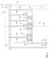
- FIG. 2is a sectional view of an exemplary fuel nozzle assembly that may be used with the turbine engine shown in FIG. 1 .
- FIG. 3is a sectional view of a portion of the fuel nozzle assembly with a simplified tube arrangement shown in FIG. 2 and taken along line 3 - 3 .
- FIG. 4is an enlarged cross-sectional view of a portion of an exemplary fuel nozzle that may be used with the fuel nozzle assembly shown in FIG. 2 and taken along area 4 .
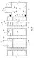
- FIG. 5is a sectional view of an alternative embodiment of the fuel nozzle assembly shown in FIG. 2 .
- FIG. 6is a sectional view of a portion of the fuel nozzle assembly shown in FIG. 5 and taken along line 6 - 6 .
- FIG. 7is an enlarged cross-sectional view of a portion of an alternative embodiment of the fuel nozzle shown in FIG. 5 and taken along area 7 .
- FIGS. 8-10are enlarged cross-sectional views of alternative embodiments of the fuel nozzle that may be used with the fuel nozzle assembly shown in FIG. 5 .
- FIG. 11is an enlarged sectional view of a portion of the fuel nozzle shown in FIG. 4 and taken along area 11 .
- FIG. 12is a sectional view of a portion of the fuel nozzle shown FIG. 11 and taken along line 12 - 12 .
- FIGS. 13-15are enlarged sectional views of alternative embodiments of the fuel nozzle shown in FIG. 11 .
- a fuel nozzle assemblythat includes a mixing tube that is coupled to a cooling fluid plenum that enables cooling fluid to be channeled through and/or around the mixing tube into a combustion chamber to facilitate reducing flame holding/flashback events and reduce NO X emissions.
- the mixing tubeincludes a fuel aperture that enables fuel to be channeled into the mixing tube, and a cooling aperture that is downstream of the fuel aperture to enable cooling fluid to be channeled into the mixing tube such that a boundary layer is formed between the fuel mixture and the mixing tube.
- the mixing tubefacilitates reducing the probability of flame holding/flashback of the fuel nozzle.
- the fuel nozzle assemblyincludes a plurality of openings that are oriented about the mixing tube to enable cooling fluid to be channeled into the combustion chamber to facilitate reducing the formation of eddies that may induce screech tone frequencies within the fuel nozzle assembly. By reducing the formation of such eddies, undesired vibrations that may cause damage to the fuel nozzle assembly are facilitated to be reduced, such that the operating efficiency and useful life of the turbine engine are increased.
- cooling fluidrefers to nitrogen, air, fuel, inert gases, or some combination thereof, and/or any other fluid that enables the fuel nozzle to function as described herein.
- upstreamrefers to a forward end of a turbine engine
- downstreamrefers to an aft end of a turbine engine.
- FIG. 1is a schematic view of an exemplary turbine engine 10 .
- Turbine engine 10includes an intake section 12 , a compressor section 14 that is downstream from intake section 12 , a combustor section 16 downstream from compressor section 14 , a turbine section 18 downstream from combustor section 16 , and an exhaust section 20 downstream from turbine section 18 .
- Turbine section 18is coupled to compressor section 14 via a rotor assembly 22 that includes a shaft 24 that extends along a centerline axis 26 .
- turbine section 18is rotatably coupled to compressor section 14 and to a load 28 such as, but not limited to, an electrical generator and/or a mechanical drive application.
- combustor section 16includes a plurality of combustor assemblies 30 that are each coupled in flow communication with compressor section 14 .
- Each combustor assembly 30includes a fuel nozzle assembly 34 that is coupled to a combustion chamber 36 .
- each fuel nozzle assembly 34includes a plurality of fuel nozzles 38 that are coupled to combustion chamber 36 for delivering a fuel-air mixture to combustion chamber 36 .
- a fuel supply system 40is coupled to each fuel nozzle assembly 34 for channeling a flow of fuel to fuel nozzle assembly 34 .
- a cooling fluid system 42is coupled to each fuel nozzle assembly 34 for channeling a flow of cooling fluid to each fuel nozzle assembly 34 .
- Combustor assembly 30injects fuel, for example, natural gas and/or fuel oil, into the air flow, ignites the fuel-air mixture to expand the fuel-air mixture through combustion, and generates high temperature combustion gases. Combustion gases are discharged from combustor assembly 30 towards turbine section 18 wherein thermal energy in the gases is converted to mechanical rotational energy. Combustion gases impart rotational energy to turbine section 18 and to rotor assembly 22 , which subsequently provides rotational power to compressor section 14 .
- fuelfor example, natural gas and/or fuel oil
- FIG. 2is a sectional view of an exemplary fuel nozzle assembly 34 .
- FIG. 3is a sectional view of a portion of fuel nozzle assembly 34 with simplified tube arrangement taken along line 3 - 3 in FIG. 2 .
- FIG. 4is an enlarged cross-sectional view of a portion of fuel nozzle 38 taken along area 4 in FIG. 2 .
- combustor assembly 30includes a casing 44 that defines a chamber 46 therein.
- An end cover 48is coupled to an outer portion 50 of casing 44 such that an air plenum 52 is defined within chamber 46 .
- Compressor section 14(shown in FIG. 1 ) is coupled in flow communication with chamber 46 to channel compressed air downstream from compressor section 14 to air plenum 52 .
- each combustor assembly 30includes a combustor liner 54 that is positioned within chamber 46 and that is coupled in flow communication with turbine section 18 (shown in FIG. 1 ) through a transition piece (not shown) and with compressor section 14 .
- Combustor liner 54includes a substantially cylindrically-shaped inner surface 56 that defines a combustion chamber 36 that extends axially along a centerline axis 58 .
- Combustor liner 54is coupled to fuel nozzle assembly 34 to enable fuel to be channeled into combustion chamber 36 .
- Combustion chamber 36defines a combustion gas flow path 60 that extends from fuel nozzle assembly 34 to turbine section 18 .
- fuel nozzle assembly 34receives a flow of air from air plenum 52 , receives a flow of fuel from fuel supply system 40 , and channels a mixture of fuel/air into combustion chamber 36 to generate combustion gases.
- Fuel nozzle assembly 34includes a plurality of fuel nozzles 38 that are at least partially positioned within air plenum 52 and that are coupled to combustor liner 54 .
- fuel nozzle assembly 34includes a plurality of outer nozzles 62 that are circumferentially-spaced about a center nozzle 64 .
- Center nozzle 64is oriented along centerline axis 58 .
- an end plate 70is coupled to an outer portion 72 of combustor liner 54 such that combustion chamber 36 is defined between end plate 70 and combustor liner 54 .
- End plate 70includes a plurality of openings 74 that extends through end plate 70 and that are each sized and shaped to receive a fuel nozzle 38 therethrough.
- Each fuel nozzle 38is positioned within a corresponding opening 74 such that nozzle 38 is coupled in flow communication with combustion chamber 36 .
- fuel nozzle assembly 34does not include end plate 70 , and fuel nozzle 34 is coupled to an adjacent fuel nozzle 34 .
- each fuel nozzle 38includes a housing 84 that includes a sidewall 86 that extends between a forward endwall 88 and an opposite aft endwall 90 .
- Aft endwall 90is between forward endwall 88 and combustion chamber 36 , and includes an outer surface 92 that at least partially defines combustion chamber 36 .
- Sidewall 86includes a radially outer surface 94 and a radially inner surface 96 .
- Radially inner surface 96defines a substantially cylindrical cavity 98 that extends between forward endwall 88 and aft endwall 90 , along a longitudinal axis 100 .
- An interior wall 102is positioned within cavity 98 and extends inward from inner surface 96 such that a fuel plenum 104 is defined between interior wall 102 and forward endwall 88 , and such that a cooling fluid plenum 106 is defined between interior wall 102 and aft endwall 90 .
- interior wall 102is oriented such that cooling fluid plenum 106 is downstream from fuel plenum 104 along longitudinal axis 100 .
- interior wall 102may be oriented such that cooling fluid plenum 106 is upstream of fuel plenum 104 .
- a fuel conduit 108is coupled in flow communication with fuel plenum 104 for channeling fuel from fuel supply system 40 to fuel plenum 104 .
- Fuel conduit 108extends between end cover 48 and housing 84 and includes an inner surface 110 that defines a fuel channel 112 that is coupled to fuel plenum 104 .
- fuel conduit 108is coupled to forward endwall 88 and is oriented with respect to an opening 114 that extends through forward endwall 88 to couple fuel channel 112 to fuel plenum 104 .
- a plurality of cooling conduits 116extends between cooling fluid system 42 (shown in FIG. 1 ) and fuel nozzle assembly 34 for channeling cooling fluid to fuel nozzle assembly 34 .
- each cooling conduit 116is coupled to a corresponding fuel nozzle 38 for channeling a flow of cooling fluid 118 to cooling fluid plenum 106 .
- each cooling conduit 116includes an inner surface 122 that defines a cooling channel 124 , and each is coupled to interior wall 102 such that cooling channel 124 is in flow communication with cooling fluid plenum 106 .
- cooling conduit 116is within fuel conduit 108 and extends through fuel plenum 104 to interior wall 102 .
- Cooling conduit 116is oriented with respect to an opening 126 extending through interior wall 102 such that cooling channel 124 is coupled in flow communication with cooling fluid plenum 106 . Moreover, cooling conduit 116 is configured to inject cooling fluid 118 into mixing tubes 128 to facilitate improving flame holding/flashback margin and NO x performance. In addition, cooling conduit 116 channels at least a portion of cooling fluid 118 towards aft endwall 90 , and discharges cooling fluid 118 around an outlet of mixing tubes 128 to facilitate convective cooling of aft endwall 90 .
- fuel nozzle 38includes a plurality of mixing tubes 128 that each extend through housing 84 .
- Mixing tubes 128are oriented in a plurality of rows that extend outwardly from a center portion 130 of fuel nozzle assembly 34 towards an outer surface 132 of housing 84 , and are spaced circumferentially about nozzle center portion 130 .
- Each mixing tube 128includes a substantially cylindrical inner surface 134 that defines a flow channel 136 that extends between forward endwall 88 and aft endwall 90 and along a centerline axis 138 .
- inner surface 134extends between an inlet opening 140 extending through forward endwall 88 , and an outlet opening 142 extending through aft endwall 90 , to couple air plenum 52 to combustion chamber 36 .
- each mixing tube 128extends through a plurality of openings 144 defined in interior wall 102 .
- Flow channel 136is sized and shaped to enable air 146 to be channeled from air plenum 52 into combustion chamber 36 .
- each mixing tube 128is substantially parallel to longitudinal axis 100 .
- at least one mixing tube 128may be oriented obliquely with respect to longitudinal axis 100 .
- At least one mixing tube 128includes at least one fuel aperture 148 , and at least one cooling fluid aperture 150 defined therein.
- Fuel aperture 148extends through mixing tube inner surface 134 to couple fuel plenum 104 to flow channel 136 .
- Fuel aperture 148is configured to enable fuel 152 to be channeled from fuel plenum 104 to flow channel 136 to facilitate mixing fuel 152 with air 146 to form a fuel-air mixture 154 that is channeled to combustion chamber 36 .
- fuel aperture 148extends along a centerline axis 156 that is oriented substantially perpendicular to flow channel axis 138 .
- fuel aperture 148may be oriented obliquely with respect to flow channel axis 138 .
- Cooling fluid aperture 150extends through mixing tube inner surface 134 to couple cooling fluid plenum 106 to flow channel 136 .
- cooling fluid aperture 150extends along a centerline axis 157 that is oriented obliquely with respect to flow channel axis 138 .
- Cooling fluid aperture 150is sized and shaped to discharge cooling fluid 118 into flow channel 136 to facilitate forming a boundary layer 158 between mixing tube inner surface 134 and fuel-air mixture 154 , and to facilitate reducing flame holding/flashback events within mixing tube 128 .
- cooling fluid aperture 150is oriented with respect to flow channel axis 158 such that cooling fluid 118 is discharged obliquely towards outlet opening 142 .
- cooling fluid aperture 150may be oriented substantially perpendicularly with respect to flow channel axis 158 .
- cooling fluid aperture 150may be oriented to discharge cooling fluid 118 towards inlet opening 140 .
- FIG. 5is a sectional view of an alternative embodiment of fuel nozzle assembly 34 .
- FIG. 6is a sectional view of a portion of fuel nozzle assembly 34 and taken along line 6 - 6 .
- FIG. 7is an enlarged cross-sectional view of a portion of fuel nozzle 38 and taken along area 7 shown in FIG. 5 .
- Identical components shown in FIGS. 5-7are labeled with the same reference numbers used in FIGS. 2-4 .
- an impingement plate 159is coupled to end plate 70 and is spaced a distance outwardly from end plate 70 such that a chamber 160 is defined between end plate 70 and impingement plate 159 .
- Sidewall outer surface 94is coupled to end plate 70 and impingement plate 159 such that chamber 160 is defined between outer surface 94 , impingement plate 159 , and end plate 70 .
- Sidewall 86includes at least one opening 161 that extends through sidewall outer surface 94 to coupled cooling fluid plenum 106 with chamber 160 .
- Cooling conduit 116is coupled to sidewall outer surface 94 and oriented with respect to opening 161 to couple cooling channel 124 in flow communication with cooling fluid plenum 106 . More specifically, cooling conduit 116 is coupled to impingement plate 159 such that cooling channel 124 is in flow communication with chamber 160 .
- Opening 161is sized and shaped to enable cooling fluid to be channeled from cooling channel 124 to cooling fluid plenum 106 .
- cooling conduit 116is oriented to channel cooling fluid 118 towards end plate 70 to facilitate convective cooling of end plate 70 .
- each cooling conduit 116is coupled to a cooling manifold 162 that includes a plurality of valves (not shown) that correspond to each cooling conduit 116 to enable cooling fluid to be selectively channeled to each cooling conduit 116 .
- FIGS. 8-10are enlarged cross-sectional views of alternative embodiments of fuel nozzle 38 . Identical components shown in FIGS. 8-10 are labeled with the same reference numbers used in FIG. 7 .
- impingement plate 159includes a plurality of impingement openings 163 that are each sized and shaped to enable air from air plenum 52 to be channeled into chamber 160 to facilitate impingement cooling of end plate 70 .
- end plate 70includes a plurality of effusion openings 164 that extend through end plate 70 and are each sized and shaped to enable air to be channeled from chamber 160 into combustion chamber 36 to facilitate cooling of end plate 70 .
- a separation wall 165extends between cooling conduit 116 and end plate 70 to isolate cooling channel 124 from chamber 160 . Separation wall 165 is sized and shaped to channel cooling fluid 118 from cooling channel 124 to cooling fluid plenum 106 through opening 161 .
- a divider wall 166is coupled to cooling conduit 116 such that divider wall 166 at least partially defines cooling channel 124 .
- Divider wall 166is positioned between cooling conduit 116 and housing 84 such that a chamber 167 is defined between divider wall 166 and sidewall outer surface 94 .
- Divider wall 166includes at least one opening 168 that extends through divider wall 166 to couple cooling channel 124 in flow communication with chamber 167 such that cooling fluid 118 is channeled from cooling channel 124 , through chamber 167 , and to cooling fluid plenum 106 .
- separation wall 165includes at least one opening 169 to coupled cooling channel 124 in flow communication with chamber 160 .
- impingement plate 159 and end plate 70may not include openings 163 and 164 , respectively.
- FIG. 11is an enlarged sectional view of a portion of fuel nozzle 38 and taken along area 11 shown in FIG. 4 .
- FIG. 12is a sectional view of a portion of fuel nozzle 38 taken along line 12 - 12 and shown FIG. 11 .
- Identical components shown in FIGS. 11 and 12are labeled with the same reference numbers used in FIGS. 2-4 .
- aft endwall 90includes a plurality of cooling openings 170 that extend through aft endwall 90 to enable cooling fluid 118 to be channeled from cooling fluid plenum 106 into combustion chamber 36 . Cooling openings 170 are spaced circumferentially about mixing tube 128 .
- fuel nozzle assembly 34includes at least one set 172 of cooling openings 170 that are spaced circumferentially about an outer surface 174 of at least one mixing tube 128 .
- fuel nozzle assembly 34includes a plurality of sets 172 of cooling opening 170 that are each oriented with respect to a corresponding mixing tube 128 .
- Each cooling opening 170is sized and shaped to discharge cooling fluid 118 towards combustion chamber 36 to enable combustion flow dynamics downstream of endwall outer surface 92 to be adjusted such that secondary mixing of fuel and air through opening 170 and outlet opening 142 occurs to facilitate improving fuel and air mixing, and to facilitate reducing an amplitude of screech tone frequency noise generated during operation of combustor assembly 30 .
- each cooling opening 170includes an inner surface 176 that extends along a centerline axis 178 that is oriented substantially parallel to mixing tube axis 138 .
- each cooling opening 170may be oriented obliquely with respect to mixing tube axis 138 .
- each cooling opening 170is oriented such that cooling fluid 118 is discharged towards mixing tube flow channel 136 .
- each cooling opening 170is oriented such that cooling fluid 118 is discharged away from mixing tube 128 .
- FIGS. 13-15are enlarged sectional views of an alternative fuel nozzle 180 . Identical components shown in FIGS. 13-15 are labeled with the same reference numbers used in FIG. 11 .
- mixing tube 128includes an inner surface 134 that extends a distance 181 outwardly from aft endwall outer surface 92 , and towards combustion chamber 36 .
- Mixing tube 128also includes a tip end 182 that includes a tip surface 184 that extends between inner surface 134 and outer surface 174 .
- tip surface 184is oriented at a first oblique angle ⁇ l with respect to aft endwall outer surface 92 .
- Each cooling opening 170is oriented at a second oblique angle ⁇ 2 that is approximately equal to first oblique angle ⁇ 1 such that each cooling channel discharges cooling fluid along tip surface 184 , and towards flow channel 136 .
- mixing tube 128includes at least one slot 186 that is defined along mixing tube outer surface 174 to couple cooling fluid plenum 106 in flow communication with combustion chamber 36 .
- Slot 186is sized and shaped to discharge cooling fluid 118 from cooling fluid plenum 106 to combustion chamber 36 to facilitate forming a jet layer 188 around mixing tube outer surface 174 , and across aft endwall 90 to adjust combustion flow dynamics downstream of endwall outer surface 92 such that secondary mixing of fuel and air through slot 186 and outlet opening 142 occurs to facilitate improving fuel and air mixing, and to reduce an amplitude of screech tone frequency noise generated during operation of combustor assembly 30 .
- slot 186is oriented substantially parallel to flow channel 136 .
- slot 186may be oriented obliquely with respect to flow channel 136 such that slot 186 extends from outer surface 174 towards inner surface 134 .
- mixing tube 128includes a plurality of slots 186 oriented circumferentially about outer surface 174 . In another embodiment, mixing tube 128 extends outwardly from endwall outer surface 92 as shown in FIG. 13 .
- mixing tube 128includes at least one channel 190 extending from outer surface 174 towards mixing tube inner surface 122 .
- Channel 190extends through tip surface 184 to couple cooling fluid plenum 106 in flow communication with combustion chamber 36 .
- Channel 190is sized and shaped to enable cooling fluid to be channeled from cooling fluid 118 from cooling fluid plenum 106 to combustion chamber 36 to facilitate secondary mixing of fuel and air through channel 190 and outlet opening 142 .
- cooling fluid aperture 150are selected to facilitate channeling cooling fluid into mixing tube 128 to facilitate reducing a flame holding/flashback event and to facilitate mixing fuel/air mixture with cooling fluid.
- size, shape, and orientation of cooling openings 170 , slot 186 , and channel 190are selected to facilitate forming a jet layer across aft endwall 90 and within combustion chamber 36 to adjust combustion flow dynamics and to facilitate reducing the amplitude of screech tone frequencies that cause undesired vibrations within fuel nozzle assembly 34 .
- a fuel nozzle assemblythat includes a mixing tube that is coupled to a cooling fluid plenum such that cooling fluid may be channeled into the mixing tube to facilitate forming a boundary layer between a fuel/air mixture and the mixing tube to reduce undesirable flame holding/flashback events.
- the mixing tubeincludes a fuel aperture that enables fuel to be channeled into the mixing tube, and a cooling aperture that is downstream of the fuel aperture to enable cooling fluid to be channeled into the mixing tube such that a boundary layer is formed between the fuel mixture and the mixing tube.
- the fuel nozzle assemblyincludes a plurality of openings that are oriented about the mixing tube to enable cooling fluid to be channeled into the combustion chamber to generate secondary mixing of the fuel/air mixture with cooling fluid to reduce NOx formation, and to facilitate reducing the formation of eddies that may induce screech tone frequencies within the fuel nozzle assembly.
- eddiesthat may induce screech tone frequencies within the fuel nozzle assembly.
- Exemplary embodiments of a combustor assembly for use in a turbine engine and methods for assembling the sameare described above in detail.
- the methods and apparatusare not limited to the specific embodiments described herein, but rather, components of systems and/or steps of the method may be utilized independently and separately from other components and/or steps described herein.
- the methods and apparatusmay also be used in combination with other combustion systems and methods, and are not limited to practice with only the turbine engine assembly as described herein. Rather, the exemplary embodiment can be implemented and utilized in connection with many other combustion system applications.
Landscapes
- Engineering & Computer Science (AREA)
- Chemical & Material Sciences (AREA)
- Combustion & Propulsion (AREA)
- Mechanical Engineering (AREA)
- General Engineering & Computer Science (AREA)
- Turbine Rotor Nozzle Sealing (AREA)
- Gas Burners (AREA)
- Fuel-Injection Apparatus (AREA)
Abstract
Description
Claims (27)
Priority Applications (5)
| Application Number | Priority Date | Filing Date | Title |
|---|---|---|---|
| US13/342,303US8438851B1 (en) | 2012-01-03 | 2012-01-03 | Combustor assembly for use in a turbine engine and methods of assembling same |
| JP2012238466AJP6030919B2 (en) | 2012-01-03 | 2012-10-30 | Combustor assembly used in turbine engine and method of assembling the same |
| EP12190986.5AEP2613083B1 (en) | 2012-01-03 | 2012-11-01 | Fuel nozzle assembly for use in a turbine engine and methods of assembling same |
| RU2012146617/06ARU2605164C2 (en) | 2012-01-03 | 2012-11-02 | Fuel nozzles unit and unit of combustion chamber |
| CN201210431811.8ACN103185353B (en) | 2012-01-03 | 2012-11-02 | Burner assembly in turbogenerator and assemble method thereof |
Applications Claiming Priority (1)
| Application Number | Priority Date | Filing Date | Title |
|---|---|---|---|
| US13/342,303US8438851B1 (en) | 2012-01-03 | 2012-01-03 | Combustor assembly for use in a turbine engine and methods of assembling same |
Publications (1)
| Publication Number | Publication Date |
|---|---|
| US8438851B1true US8438851B1 (en) | 2013-05-14 |
Family
ID=47172450
Family Applications (1)
| Application Number | Title | Priority Date | Filing Date |
|---|---|---|---|
| US13/342,303ActiveUS8438851B1 (en) | 2012-01-03 | 2012-01-03 | Combustor assembly for use in a turbine engine and methods of assembling same |
Country Status (5)
| Country | Link |
|---|---|
| US (1) | US8438851B1 (en) |
| EP (1) | EP2613083B1 (en) |
| JP (1) | JP6030919B2 (en) |
| CN (1) | CN103185353B (en) |
| RU (1) | RU2605164C2 (en) |
Cited By (36)
| Publication number | Priority date | Publication date | Assignee | Title |
|---|---|---|---|---|
| US20130104551A1 (en)* | 2011-10-26 | 2013-05-02 | Jong Ho Uhm | Fuel injection assembly for use in turbine engines and method of assembling same |
| US20130177858A1 (en)* | 2012-01-06 | 2013-07-11 | General Electric Company | Combustor and method for distributing fuel in the combustor |
| US20130241089A1 (en)* | 2012-03-19 | 2013-09-19 | General Electric Company | Micromixer Combustion Head End Assembly |
| US20140190169A1 (en)* | 2013-01-04 | 2014-07-10 | General Electric Company | Coaxial Fuel Supply for a Micromixer |
| US20150167982A1 (en)* | 2013-12-13 | 2015-06-18 | General Electric Company | Bundled tube fuel injector |
| WO2015176887A1 (en)* | 2014-05-19 | 2015-11-26 | Siemens Aktiengesellschaft | Burner arrangement with resonator |
| US20160091207A1 (en)* | 2014-09-29 | 2016-03-31 | Mitsubishi Hitachi Power Systems, Ltd. | Combustor and gas turbine having the same |
| US20160178206A1 (en)* | 2013-10-18 | 2016-06-23 | Mitsubishi Heavy Industries, Ltd. | Fuel injector |
| US9657642B2 (en) | 2014-03-27 | 2017-05-23 | Honeywell International Inc. | Turbine sections of gas turbine engines with dual use of cooling air |
| EP3205939A1 (en)* | 2016-02-09 | 2017-08-16 | General Electric Company | Fuel injectors and methods of fabricating same |
| US20180094815A1 (en)* | 2016-09-30 | 2018-04-05 | Doosan Heavy Industries & Construction Co., Ltd. | Damping Liner Cap and Gas Turbine Combustor |
| US20180172276A1 (en)* | 2016-12-21 | 2018-06-21 | General Electric Company | Fuel Nozzle Assembly with Flange Orifice |
| US10890329B2 (en) | 2018-03-01 | 2021-01-12 | General Electric Company | Fuel injector assembly for gas turbine engine |
| US10935245B2 (en) | 2018-11-20 | 2021-03-02 | General Electric Company | Annular concentric fuel nozzle assembly with annular depression and radial inlet ports |
| US11073114B2 (en) | 2018-12-12 | 2021-07-27 | General Electric Company | Fuel injector assembly for a heat engine |
| US11079113B2 (en) | 2017-04-28 | 2021-08-03 | Mitsubishi Power, Ltd. | Fuel injector and gas turbine |
| US11156360B2 (en) | 2019-02-18 | 2021-10-26 | General Electric Company | Fuel nozzle assembly |
| US11274832B2 (en) | 2017-11-30 | 2022-03-15 | Mitsubishi Power, Ltd. | Fuel injector, combustor, and gas turbine |
| US11286884B2 (en) | 2018-12-12 | 2022-03-29 | General Electric Company | Combustion section and fuel injector assembly for a heat engine |
| US11339969B2 (en)* | 2019-10-01 | 2022-05-24 | Mitsubishi Heavy Industries, Ltd. | Gas turbine combustor |
| EP4027059A1 (en)* | 2021-01-12 | 2022-07-13 | Crosstown Power GmbH | Burner, combustor, and method for retrofitting a combustion appliance |
| US20220243918A1 (en)* | 2021-02-03 | 2022-08-04 | Doosan Heavy Industries & Construction Co., Ltd. | Injection nozzle, combustor including same nozzle, and gas turbine including same combustor |
| US20220260254A1 (en)* | 2021-02-17 | 2022-08-18 | Doosan Heavy Industries & Construction Co., Ltd. | Micro-mixer module and combustor having the same |
| DE102022103746A1 (en) | 2022-02-17 | 2023-08-17 | Deutsches Zentrum für Luft- und Raumfahrt e.V. | Burner system for generating hot gas |
| US11970977B2 (en) | 2022-08-26 | 2024-04-30 | Hamilton Sundstrand Corporation | Variable restriction of a secondary circuit of a fuel injector |
| EP4379263A1 (en)* | 2022-11-30 | 2024-06-05 | Doosan Enerbility Co., Ltd. | Nozzle assembly, combustor, and gas turbine including same |
| US20240271571A1 (en)* | 2023-02-14 | 2024-08-15 | Collins Engine Nozzles, Inc. | Proportional control of cooling circuit of fuel nozzle |
| US20240271790A1 (en)* | 2023-02-14 | 2024-08-15 | Collins Engine Nozzles, Inc. | Variable cooling of secondary circuit of fuel nozzles |
| US12215866B2 (en) | 2022-02-18 | 2025-02-04 | General Electric Company | Combustor for a turbine engine having a fuel-air mixer including a set of mixing passages |
| US12270343B2 (en) | 2022-08-26 | 2025-04-08 | Collins Engine Nozzles, Inc. | Proportional restriction of fuel nozzle with an auxiliary circuit |
| US12281795B1 (en)* | 2024-03-11 | 2025-04-22 | Rtx Corporation | Cluster of swirled mini-mixers for fuel-staged, axially staged combustion |
| US12286931B2 (en) | 2022-08-26 | 2025-04-29 | Collins Engine Nozzles, Inc. | Variable restriction of a fuel circuit of a fuel nozzle |
| US12305581B2 (en) | 2022-08-26 | 2025-05-20 | Collins Engine Nozzles, Inc. | Proportional restriction of a secondary circuit of a fuel injector |
| US12313004B2 (en) | 2022-08-26 | 2025-05-27 | Collins Engine Nozzles, Inc. | Proportional force modification of passive spool for control of secondary nozzle circuits |
| US20250189134A1 (en)* | 2023-12-08 | 2025-06-12 | Doosan Enerbility Co., Ltd. | Combustor nozzle, combustor, and gas turbine including same |
| US12352444B2 (en) | 2023-05-02 | 2025-07-08 | Doosan Enerbility Co., Ltd. | Combustor nozzle, combustor, and gas turbine including same |
Families Citing this family (5)
| Publication number | Priority date | Publication date | Assignee | Title |
|---|---|---|---|---|
| US9267690B2 (en)* | 2012-05-29 | 2016-02-23 | General Electric Company | Turbomachine combustor nozzle including a monolithic nozzle component and method of forming the same |
| US9212822B2 (en)* | 2012-05-30 | 2015-12-15 | General Electric Company | Fuel injection assembly for use in turbine engines and method of assembling same |
| US20150198332A1 (en)* | 2014-01-16 | 2015-07-16 | General Electric Company | Channel defining fuel nozzle of combustion system |
| EP3186559B1 (en)* | 2014-08-26 | 2020-10-14 | Siemens Energy, Inc. | Cooling system for fuel nozzles within combustor in a turbine engine |
| CN115031259B (en)* | 2022-03-18 | 2023-06-02 | 北京航空航天大学 | Combustion chamber of a gas turbine and design method thereof |
Citations (15)
| Publication number | Priority date | Publication date | Assignee | Title |
|---|---|---|---|---|
| US3943705A (en)* | 1974-11-15 | 1976-03-16 | Westinghouse Electric Corporation | Wide range catalytic combustor |
| US4100733A (en)* | 1976-10-04 | 1978-07-18 | United Technologies Corporation | Premix combustor |
| US7513115B2 (en) | 2005-05-23 | 2009-04-07 | Power Systems Mfg., Llc | Flashback suppression system for a gas turbine combustor |
| US20100146984A1 (en) | 2007-05-08 | 2010-06-17 | Richard Carroni | Gas turbine with water injection |
| US20100180564A1 (en) | 2009-01-21 | 2010-07-22 | General Electric Company | Systems and Methods for Mitigating a Flashback Condition in a Premixed Combustor |
| US20100218501A1 (en)* | 2009-02-27 | 2010-09-02 | General Electric Company | Premixed direct injection disk |
| US20100252652A1 (en)* | 2009-04-03 | 2010-10-07 | General Electric Company | Premixing direct injector |
| US20100275601A1 (en)* | 2009-05-01 | 2010-11-04 | General Electric Company | Turbine air flow conditioner |
| US20110083439A1 (en)* | 2009-10-08 | 2011-04-14 | General Electric Corporation | Staged Multi-Tube Premixing Injector |
| US7942038B2 (en) | 2009-01-21 | 2011-05-17 | General Electric Company | Systems and methods of monitoring acoustic pressure to detect a flame condition in a gas turbine |
| US7959880B2 (en) | 2004-04-27 | 2011-06-14 | Velocys, Inc. | Hydrogen peroxide production in microchannel reactors |
| US20120058437A1 (en)* | 2010-09-08 | 2012-03-08 | General Electric Company | Apparatus and method for mixing fuel in a gas turbine nozzle |
| US20120180495A1 (en)* | 2011-01-18 | 2012-07-19 | General Electric Company | System and method for injecting fuel |
| US20120192566A1 (en)* | 2011-01-28 | 2012-08-02 | Jong Ho Uhm | Fuel injection assembly for use in turbine engines and method of assembling same |
| US20120198856A1 (en)* | 2011-02-04 | 2012-08-09 | General Electric Company | Turbine combustor configured for high-frequency dynamics mitigation and related method |
Family Cites Families (5)
| Publication number | Priority date | Publication date | Assignee | Title |
|---|---|---|---|---|
| RU2145039C1 (en)* | 1999-03-18 | 2000-01-27 | Федеральное государственное унитарное предприятие "Исследовательский центр им.М.В.Келдыша" | Method and device for fuel feed to thermal engine chamber |
| US7878000B2 (en)* | 2005-12-20 | 2011-02-01 | General Electric Company | Pilot fuel injector for mixer assembly of a high pressure gas turbine engine |
| US20110162377A1 (en)* | 2010-01-06 | 2011-07-07 | General Electric Company | Turbomachine nozzle |
| JP5372814B2 (en)* | 2010-03-17 | 2013-12-18 | 株式会社日立製作所 | Gas turbine combustor and operation method |
| US8307655B2 (en)* | 2010-05-20 | 2012-11-13 | General Electric Company | System for cooling turbine combustor transition piece |
- 2012
- 2012-01-03USUS13/342,303patent/US8438851B1/enactiveActive
- 2012-10-30JPJP2012238466Apatent/JP6030919B2/enactiveActive
- 2012-11-01EPEP12190986.5Apatent/EP2613083B1/enactiveActive
- 2012-11-02RURU2012146617/06Apatent/RU2605164C2/ennot_activeIP Right Cessation
- 2012-11-02CNCN201210431811.8Apatent/CN103185353B/enactiveActive
Patent Citations (15)
| Publication number | Priority date | Publication date | Assignee | Title |
|---|---|---|---|---|
| US3943705A (en)* | 1974-11-15 | 1976-03-16 | Westinghouse Electric Corporation | Wide range catalytic combustor |
| US4100733A (en)* | 1976-10-04 | 1978-07-18 | United Technologies Corporation | Premix combustor |
| US7959880B2 (en) | 2004-04-27 | 2011-06-14 | Velocys, Inc. | Hydrogen peroxide production in microchannel reactors |
| US7513115B2 (en) | 2005-05-23 | 2009-04-07 | Power Systems Mfg., Llc | Flashback suppression system for a gas turbine combustor |
| US20100146984A1 (en) | 2007-05-08 | 2010-06-17 | Richard Carroni | Gas turbine with water injection |
| US7942038B2 (en) | 2009-01-21 | 2011-05-17 | General Electric Company | Systems and methods of monitoring acoustic pressure to detect a flame condition in a gas turbine |
| US20100180564A1 (en) | 2009-01-21 | 2010-07-22 | General Electric Company | Systems and Methods for Mitigating a Flashback Condition in a Premixed Combustor |
| US20100218501A1 (en)* | 2009-02-27 | 2010-09-02 | General Electric Company | Premixed direct injection disk |
| US20100252652A1 (en)* | 2009-04-03 | 2010-10-07 | General Electric Company | Premixing direct injector |
| US20100275601A1 (en)* | 2009-05-01 | 2010-11-04 | General Electric Company | Turbine air flow conditioner |
| US20110083439A1 (en)* | 2009-10-08 | 2011-04-14 | General Electric Corporation | Staged Multi-Tube Premixing Injector |
| US20120058437A1 (en)* | 2010-09-08 | 2012-03-08 | General Electric Company | Apparatus and method for mixing fuel in a gas turbine nozzle |
| US20120180495A1 (en)* | 2011-01-18 | 2012-07-19 | General Electric Company | System and method for injecting fuel |
| US20120192566A1 (en)* | 2011-01-28 | 2012-08-02 | Jong Ho Uhm | Fuel injection assembly for use in turbine engines and method of assembling same |
| US20120198856A1 (en)* | 2011-02-04 | 2012-08-09 | General Electric Company | Turbine combustor configured for high-frequency dynamics mitigation and related method |
Cited By (54)
| Publication number | Priority date | Publication date | Assignee | Title |
|---|---|---|---|---|
| US8984888B2 (en)* | 2011-10-26 | 2015-03-24 | General Electric Company | Fuel injection assembly for use in turbine engines and method of assembling same |
| US20130104551A1 (en)* | 2011-10-26 | 2013-05-02 | Jong Ho Uhm | Fuel injection assembly for use in turbine engines and method of assembling same |
| US20130177858A1 (en)* | 2012-01-06 | 2013-07-11 | General Electric Company | Combustor and method for distributing fuel in the combustor |
| US9134023B2 (en)* | 2012-01-06 | 2015-09-15 | General Electric Company | Combustor and method for distributing fuel in the combustor |
| US20130241089A1 (en)* | 2012-03-19 | 2013-09-19 | General Electric Company | Micromixer Combustion Head End Assembly |
| US9163839B2 (en)* | 2012-03-19 | 2015-10-20 | General Electric Company | Micromixer combustion head end assembly |
| US20140190169A1 (en)* | 2013-01-04 | 2014-07-10 | General Electric Company | Coaxial Fuel Supply for a Micromixer |
| US9151503B2 (en)* | 2013-01-04 | 2015-10-06 | General Electric Company | Coaxial fuel supply for a micromixer |
| US20160178206A1 (en)* | 2013-10-18 | 2016-06-23 | Mitsubishi Heavy Industries, Ltd. | Fuel injector |
| US11022314B2 (en) | 2013-10-18 | 2021-06-01 | Mitsubishi Heavy Industries, Ltd. | Fuel injector, combustor, and gas turbine |
| US10274200B2 (en)* | 2013-10-18 | 2019-04-30 | Mitsubishi Heavy Industries, Ltd. | Fuel injector, combustor, and gas turbine |
| US9664392B2 (en)* | 2013-12-13 | 2017-05-30 | General Electric Company | Bundled tube fuel injector with outer shroud and outer band connection |
| US20150167982A1 (en)* | 2013-12-13 | 2015-06-18 | General Electric Company | Bundled tube fuel injector |
| US9657642B2 (en) | 2014-03-27 | 2017-05-23 | Honeywell International Inc. | Turbine sections of gas turbine engines with dual use of cooling air |
| US10605457B2 (en) | 2014-05-19 | 2020-03-31 | Siemens Aktiengesellschaft | Burner arrangement with resonator |
| CN106461222A (en)* | 2014-05-19 | 2017-02-22 | 西门子公司 | Burner installation with resonator |
| WO2015176887A1 (en)* | 2014-05-19 | 2015-11-26 | Siemens Aktiengesellschaft | Burner arrangement with resonator |
| CN106461222B (en)* | 2014-05-19 | 2019-03-15 | 西门子公司 | Burner device with resonator |
| US10190775B2 (en)* | 2014-09-29 | 2019-01-29 | Mitsubishi Hitachi Power Systems, Ltd. | Combustor and gas turbine having the same |
| US20160091207A1 (en)* | 2014-09-29 | 2016-03-31 | Mitsubishi Hitachi Power Systems, Ltd. | Combustor and gas turbine having the same |
| EP3205939A1 (en)* | 2016-02-09 | 2017-08-16 | General Electric Company | Fuel injectors and methods of fabricating same |
| US20180094815A1 (en)* | 2016-09-30 | 2018-04-05 | Doosan Heavy Industries & Construction Co., Ltd. | Damping Liner Cap and Gas Turbine Combustor |
| US10670271B2 (en)* | 2016-09-30 | 2020-06-02 | DOOSAN Heavy Industries Construction Co., LTD | Acoustic dampening liner cap and gas turbine combustor including the same |
| US10788215B2 (en)* | 2016-12-21 | 2020-09-29 | General Electric Company | Fuel nozzle assembly with flange orifice |
| US20180172276A1 (en)* | 2016-12-21 | 2018-06-21 | General Electric Company | Fuel Nozzle Assembly with Flange Orifice |
| US11079113B2 (en) | 2017-04-28 | 2021-08-03 | Mitsubishi Power, Ltd. | Fuel injector and gas turbine |
| US11274832B2 (en) | 2017-11-30 | 2022-03-15 | Mitsubishi Power, Ltd. | Fuel injector, combustor, and gas turbine |
| US10890329B2 (en) | 2018-03-01 | 2021-01-12 | General Electric Company | Fuel injector assembly for gas turbine engine |
| US10935245B2 (en) | 2018-11-20 | 2021-03-02 | General Electric Company | Annular concentric fuel nozzle assembly with annular depression and radial inlet ports |
| US11073114B2 (en) | 2018-12-12 | 2021-07-27 | General Electric Company | Fuel injector assembly for a heat engine |
| US11286884B2 (en) | 2018-12-12 | 2022-03-29 | General Electric Company | Combustion section and fuel injector assembly for a heat engine |
| US11156360B2 (en) | 2019-02-18 | 2021-10-26 | General Electric Company | Fuel nozzle assembly |
| US11339969B2 (en)* | 2019-10-01 | 2022-05-24 | Mitsubishi Heavy Industries, Ltd. | Gas turbine combustor |
| EP4027059A1 (en)* | 2021-01-12 | 2022-07-13 | Crosstown Power GmbH | Burner, combustor, and method for retrofitting a combustion appliance |
| US20240060644A1 (en)* | 2021-01-12 | 2024-02-22 | Crosstown H2R Ag | Burner |
| WO2022152622A1 (en)* | 2021-01-12 | 2022-07-21 | Crosstown Power Gmbh | Burner |
| US20220243918A1 (en)* | 2021-02-03 | 2022-08-04 | Doosan Heavy Industries & Construction Co., Ltd. | Injection nozzle, combustor including same nozzle, and gas turbine including same combustor |
| US11846424B2 (en)* | 2021-02-03 | 2023-12-19 | Doosan Enerbility Co., Ltd. | Injection nozzle, combustor including same nozzle, and gas turbine including same combustor |
| US12049844B2 (en)* | 2021-02-17 | 2024-07-30 | Doosan Enerbility Co., Ltd. | Micro-mixer module and combustor having the same |
| US20220260254A1 (en)* | 2021-02-17 | 2022-08-18 | Doosan Heavy Industries & Construction Co., Ltd. | Micro-mixer module and combustor having the same |
| DE102022103746A1 (en) | 2022-02-17 | 2023-08-17 | Deutsches Zentrum für Luft- und Raumfahrt e.V. | Burner system for generating hot gas |
| US12215866B2 (en) | 2022-02-18 | 2025-02-04 | General Electric Company | Combustor for a turbine engine having a fuel-air mixer including a set of mixing passages |
| US11970977B2 (en) | 2022-08-26 | 2024-04-30 | Hamilton Sundstrand Corporation | Variable restriction of a secondary circuit of a fuel injector |
| US12313004B2 (en) | 2022-08-26 | 2025-05-27 | Collins Engine Nozzles, Inc. | Proportional force modification of passive spool for control of secondary nozzle circuits |
| US12305581B2 (en) | 2022-08-26 | 2025-05-20 | Collins Engine Nozzles, Inc. | Proportional restriction of a secondary circuit of a fuel injector |
| US12286931B2 (en) | 2022-08-26 | 2025-04-29 | Collins Engine Nozzles, Inc. | Variable restriction of a fuel circuit of a fuel nozzle |
| US12270343B2 (en) | 2022-08-26 | 2025-04-08 | Collins Engine Nozzles, Inc. | Proportional restriction of fuel nozzle with an auxiliary circuit |
| EP4379263A1 (en)* | 2022-11-30 | 2024-06-05 | Doosan Enerbility Co., Ltd. | Nozzle assembly, combustor, and gas turbine including same |
| US12305859B2 (en) | 2022-11-30 | 2025-05-20 | Doosan Enerbility Co., Ltd. | Nozzle assembly, combustor, and gas turbine including same |
| US20240271790A1 (en)* | 2023-02-14 | 2024-08-15 | Collins Engine Nozzles, Inc. | Variable cooling of secondary circuit of fuel nozzles |
| US20240271571A1 (en)* | 2023-02-14 | 2024-08-15 | Collins Engine Nozzles, Inc. | Proportional control of cooling circuit of fuel nozzle |
| US12352444B2 (en) | 2023-05-02 | 2025-07-08 | Doosan Enerbility Co., Ltd. | Combustor nozzle, combustor, and gas turbine including same |
| US20250189134A1 (en)* | 2023-12-08 | 2025-06-12 | Doosan Enerbility Co., Ltd. | Combustor nozzle, combustor, and gas turbine including same |
| US12281795B1 (en)* | 2024-03-11 | 2025-04-22 | Rtx Corporation | Cluster of swirled mini-mixers for fuel-staged, axially staged combustion |
Also Published As
| Publication number | Publication date |
|---|---|
| EP2613083B1 (en) | 2020-08-12 |
| JP6030919B2 (en) | 2016-11-24 |
| RU2605164C2 (en) | 2016-12-20 |
| EP2613083A3 (en) | 2017-12-20 |
| CN103185353B (en) | 2016-12-21 |
| CN103185353A (en) | 2013-07-03 |
| JP2013139993A (en) | 2013-07-18 |
| EP2613083A2 (en) | 2013-07-10 |
| RU2012146617A (en) | 2014-05-10 |
Similar Documents
| Publication | Publication Date | Title |
|---|---|---|
| US8438851B1 (en) | Combustor assembly for use in a turbine engine and methods of assembling same | |
| US8943832B2 (en) | Fuel nozzle assembly for use in turbine engines and methods of assembling same | |
| EP2669580B1 (en) | Fuel injection assembly for use in turbine engines and method of assembling same | |
| KR102334882B1 (en) | Combustion system with panel fuel injectors | |
| US9222673B2 (en) | Fuel nozzle and method of assembling the same | |
| US8607569B2 (en) | Methods and systems to thermally protect fuel nozzles in combustion systems | |
| US9599343B2 (en) | Fuel nozzle for use in a turbine engine and method of assembly | |
| US9200571B2 (en) | Fuel nozzle assembly for a gas turbine engine | |
| US20080276622A1 (en) | Fuel nozzle and method of fabricating the same | |
| EP2824391A1 (en) | Air-cooled swirler-head | |
| US8555645B2 (en) | Fuel nozzle centerbody and method of assembling the same | |
| EP3290805A1 (en) | Fuel nozzle assembly with resonator | |
| US20120324898A1 (en) | Combustor assembly for use in a turbine engine and methods of assembling same | |
| US20210088216A1 (en) | Combustor and gas turbine including the same | |
| CN105715378A (en) | Separate Feedings Of Cooling And Dilution Air | |
| US20120031099A1 (en) | Combustor assembly for use in a turbine engine and methods of assembling same | |
| US8813501B2 (en) | Combustor assemblies for use in turbine engines and methods of assembling same | |
| US20180340689A1 (en) | Low Profile Axially Staged Fuel Injector | |
| US20130227928A1 (en) | Fuel nozzle assembly for use in turbine engines and method of assembling same | |
| EP2626633B1 (en) | Turbine Engine | |
| US10228135B2 (en) | Combustion liner cooling | |
| WO2023140180A1 (en) | Combustor and gas turbine |
Legal Events
| Date | Code | Title | Description |
|---|---|---|---|
| AS | Assignment | Owner name:GENERAL ELECTRIC COMPANY, NEW YORK Free format text:ASSIGNMENT OF ASSIGNORS INTEREST;ASSIGNORS:UHM, JONG HO;JOHNSON, THOMAS EDWARD;REEL/FRAME:027468/0315 Effective date:20111206 | |
| AS | Assignment | Owner name:UNITED STATE DEPARTMENT OF ENERGY, DISTRICT OF COL Free format text:CONFIRMATORY LICENSE;ASSIGNOR:GENERAL ELECTRIC COMPANY;REEL/FRAME:028466/0665 Effective date:20120222 | |
| FEPP | Fee payment procedure | Free format text:PAYOR NUMBER ASSIGNED (ORIGINAL EVENT CODE: ASPN); ENTITY STATUS OF PATENT OWNER: LARGE ENTITY | |
| STCF | Information on status: patent grant | Free format text:PATENTED CASE | |
| AS | Assignment | Owner name:ENERGY, UNITED STATES DEPARTMENT OF, DISTRICT OF C Free format text:CONFIRMATORY LICENSE;ASSIGNOR:GENERAL ELECTRIC COMPANY;REEL/FRAME:030994/0444 Effective date:20130509 | |
| FPAY | Fee payment | Year of fee payment:4 | |
| MAFP | Maintenance fee payment | Free format text:PAYMENT OF MAINTENANCE FEE, 8TH YEAR, LARGE ENTITY (ORIGINAL EVENT CODE: M1552); ENTITY STATUS OF PATENT OWNER: LARGE ENTITY Year of fee payment:8 | |
| AS | Assignment | Owner name:UNITED STATES DEPARTMENT OF ENERGY, DISTRICT OF COLUMBIA Free format text:CONFIRMATORY LICENSE;ASSIGNOR:GENERAL ELECTRIC COMPANY;REEL/FRAME:058305/0433 Effective date:20130509 | |
| AS | Assignment | Owner name:GE INFRASTRUCTURE TECHNOLOGY LLC, SOUTH CAROLINA Free format text:ASSIGNMENT OF ASSIGNORS INTEREST;ASSIGNOR:GENERAL ELECTRIC COMPANY;REEL/FRAME:065727/0001 Effective date:20231110 | |
| MAFP | Maintenance fee payment | Free format text:PAYMENT OF MAINTENANCE FEE, 12TH YEAR, LARGE ENTITY (ORIGINAL EVENT CODE: M1553); ENTITY STATUS OF PATENT OWNER: LARGE ENTITY Year of fee payment:12 |