US8438135B1 - Mirroring metadata in a continuous data protection environment - Google Patents
Mirroring metadata in a continuous data protection environmentDownload PDFInfo
- Publication number
- US8438135B1 US8438135B1US13/541,198US201213541198AUS8438135B1US 8438135 B1US8438135 B1US 8438135B1US 201213541198 AUS201213541198 AUS 201213541198AUS 8438135 B1US8438135 B1US 8438135B1
- Authority
- US
- United States
- Prior art keywords
- metadata
- data
- data protection
- stream
- protection appliance
- Prior art date
- Legal status (The legal status is an assumption and is not a legal conclusion. Google has not performed a legal analysis and makes no representation as to the accuracy of the status listed.)
- Active
Links
Images


Classifications
- G—PHYSICS
- G06—COMPUTING OR CALCULATING; COUNTING
- G06F—ELECTRIC DIGITAL DATA PROCESSING
- G06F11/00—Error detection; Error correction; Monitoring
- G06F11/07—Responding to the occurrence of a fault, e.g. fault tolerance
- G06F11/14—Error detection or correction of the data by redundancy in operation
- G06F11/1402—Saving, restoring, recovering or retrying
- G06F11/1471—Saving, restoring, recovering or retrying involving logging of persistent data for recovery
- G—PHYSICS
- G06—COMPUTING OR CALCULATING; COUNTING
- G06F—ELECTRIC DIGITAL DATA PROCESSING
- G06F11/00—Error detection; Error correction; Monitoring
- G06F11/07—Responding to the occurrence of a fault, e.g. fault tolerance
- G06F11/16—Error detection or correction of the data by redundancy in hardware
- G06F11/20—Error detection or correction of the data by redundancy in hardware using active fault-masking, e.g. by switching out faulty elements or by switching in spare elements
- G06F11/2053—Error detection or correction of the data by redundancy in hardware using active fault-masking, e.g. by switching out faulty elements or by switching in spare elements where persistent mass storage functionality or persistent mass storage control functionality is redundant
- G06F11/2056—Error detection or correction of the data by redundancy in hardware using active fault-masking, e.g. by switching out faulty elements or by switching in spare elements where persistent mass storage functionality or persistent mass storage control functionality is redundant by mirroring
- G06F11/2069—Management of state, configuration or failover
- G—PHYSICS
- G06—COMPUTING OR CALCULATING; COUNTING
- G06F—ELECTRIC DIGITAL DATA PROCESSING
- G06F11/00—Error detection; Error correction; Monitoring
- G06F11/07—Responding to the occurrence of a fault, e.g. fault tolerance
- G06F11/16—Error detection or correction of the data by redundancy in hardware
- G06F11/20—Error detection or correction of the data by redundancy in hardware using active fault-masking, e.g. by switching out faulty elements or by switching in spare elements
- G06F11/2053—Error detection or correction of the data by redundancy in hardware using active fault-masking, e.g. by switching out faulty elements or by switching in spare elements where persistent mass storage functionality or persistent mass storage control functionality is redundant
- G06F11/2056—Error detection or correction of the data by redundancy in hardware using active fault-masking, e.g. by switching out faulty elements or by switching in spare elements where persistent mass storage functionality or persistent mass storage control functionality is redundant by mirroring
- G06F11/2071—Error detection or correction of the data by redundancy in hardware using active fault-masking, e.g. by switching out faulty elements or by switching in spare elements where persistent mass storage functionality or persistent mass storage control functionality is redundant by mirroring using a plurality of controllers
- G06F11/2079—Bidirectional techniques
Definitions
- Conventional data protection systemsinclude tape backup drives, for storing organizational production site data on a periodic basis. Such systems suffer from several drawbacks. First, they require a system shutdown during backup, since the data being backed up cannot be used during the backup operation. Second, they limit the points in time to which the production site can recover. For example, if data is backed up on a daily basis, there may be several hours of lost data in the event of a disaster. Third, the data recovery process itself takes a long time.
- Another conventional data protection systemuses data replication, by creating a copy of the organization's production site data on a secondary backup storage system, and updating the backup with changes.
- the backup storage systemmay be situated in the same physical location as the production storage system, or in a physically remote location.
- Data replication systemsgenerally operate either at the application level, at the file system level, or at the data block level.
- Continuous data protection systemstry to provide continuous data protection, which enable the organization to roll back to any specified point in time within a recent history.
- Continuous data protection systemsaim to satisfy two conflicting objectives, as best as possible; namely, (i) minimize the down time, in which the organization production site data is unavailable, during a recovery, and (ii) enable recovery as close as possible to any specified point in time within a recent history.
- CDP systemsgenerally include an initialization process when synchronizing first and second volumes. While it is desirable to compare data signatures instead of actual data as much as possible for greater efficiency, there are times when signature comparison could be used but is not available in conventional CDP systems.
- a methodin one aspect, includes providing data protection to data in a first volume at a first data protection appliance by storing a copy of the data in a second volume using a second data protection appliance, tracking changes between data locations in the first volume and the second volume using a delta marking stream (DMS) and receiving, at the first data protection appliance, metadata.
- the metadatais intended to be committed to the DMS.
- the methodfurther includes mirroring the metadata at a third data protection appliance.
- an articlein another aspect, includes a non-transitory machine-readable medium that stores executable instructions to perform mirroring.
- the instructionscause a machine to provide data protection to data in a first volume at a first data protection appliance by storing a copy of the data in a second volume using second data protection appliance, track changes between data locations in the first volume and the second volume using a delta marking stream (DMS) and receive, at the first data protection appliance, metadata.
- DMSdelta marking stream
- the metadataintended to be committed to the DMS.
- the instructionsalso cause the machine to mirror the metadata at a third data protection appliance.
- an apparatus to perform mirroringincludes circuitry to provide data protection to data in a first volume at a first data protection appliance by storing a copy of the data in a second volume, track changes between data locations in the first volume and the second volume using a delta marking stream (DMS) and receive, at the first data protection appliance, metadata.
- the apparatusalso includes circuitry to mirror the metadata at a third data protection appliance.
- the second data protection applianceis the first data protection appliance.
- Mirroring the metadata at the third data protection applianceincludes mirroring the metadata at a third data protection appliance in a same cluster as the first data protection appliance. Committing the metadata to the DMS and removing the metadata from the third data protection appliance if the metadata is committed to the DMS. Mirroring includes storing the metadata at the third data protection appliance until at least one of a predefined amount of time has elapsed or the metadata reaches a predefined size.
- Storing the metadata at the third data protection applianceincludes storing the metadata using a basket system. Receiving a request to recover the metadata and acquiring the metadata at the third data protection appliance.
- Determining if the acquiring of the metadata is successfulmoving the metadata to the DMS if acquiring the metadata is successful moving the system to stable mode and performing a full sweep on the first and second volumes if acquiring the metadata is not successful.
- Receiving a request to recover the metadata and performing a full sweep on the first and second volumescomprises performing a full sweep on the first and second volumes if in a fragile mode. If mirroring fails: moving into a fragile mode if the fragile mode is allowed and moving into a stable mode if the fragile mode is not allowed.
- Establishing a connection between the first data protection appliance and the second data protection applianceconnecting a protection agent to the first data protection appliance if the connection between the first data protection appliance and the second data protection appliance has been established and sending I/Os from the protection agent to the first data protection appliance.
- FIG. 1is a simplified block diagram of a data protection system.
- FIG. 2is a simplified illustration of a journal history of write transactions for a storage system.
- FIG. 3Ais a simplified illustration of a first stage of a journal and four data streams stored therein, after recording three write transactions.
- FIG. 3Bis a simplified illustration of a second stage of a journal and four data streams stored therein, after applying a first write transactions to a storage system.
- FIG. 3Cis a simplified illustration of a third stage of a journal history and four data streams stored therein, after applying a second write transactions to a storage system.
- FIG. 3Dis a simplified illustration of a fourth stage of a journal history and four data streams stored therein, after rolling back a write transaction.
- FIGS. 4A and 4Bare a simplified flowchart of a data protection method during a normal production mode.
- FIGS. 5A and 5Bare a simplified flowchart of a data protection method during a data recovery mode, prior to completion of rollback.
- FIGS. 6A and 6Bare a simplified flowchart of a data protection method during a data recovery mode, after completion of rollback.
- FIG. 7is a simplified illustration of a time-line for tracking new processing of old data.
- FIG. 8is a simplified illustration of a five-stage journaling process for continuous data replication.
- FIG. 9is a simplified illustration of a four-stage journaling process for continuous data replication, for use when an I/O data rate is low.
- FIG. 10is a simplified illustration of a three-stage journaling process for continuous data replication, for use when an I/O data rate is high.
- FIG. 11is a simplified state diagram of transitions between 5-stage, 4-stage and 3-stage journal processing.
- FIG. 12is a simplified illustration of a variant of the three-stage journaling process shown in FIG. 10 .
- FIG. 13is a schematic depiction of a volume synchronization environment.
- FIG. 13Ais a block diagram showing data signature comparison during volume synchronization.
- FIG. 14is a schematic depiction of a distributor for data streams using during volume synchronization.
- FIG. 15is a schematic depiction of dirty location map generation as part of volume synchronization.
- FIG. 16is a flow diagram showing an exemplary sequence of steps for volume synchronization with selective data signature transmission.
- FIG. 17is a simplified block diagram of another embodiment of a data protection system.
- FIGS. 18 and 20are flow diagrams of examples of processes used in mirroring.
- FIGS. 19A and 19Bare flow diagrams of examples of processes used with a delta marking stream.
- FIG. 21is a flow diagram of an example of a process to recover mirrored metadata.
- FIG. 22is a computer on which the processes of FIGS. 18 to 21 may be implemented.
- BACKUP SITEa facility where replicated production site data is stored; the backup site may be located in a remote site or at the same location as the production site;
- DPAa computer or a cluster of computers that serve as a data protection appliance, responsible for data protection services including inter alia data replication of a storage system, and journaling of I/O requests issued by a host computer to the storage system;
- HOSTat least one computer or networks of computers that runs at least one data processing application that issues I/O requests to one or more storage systems; a host is an initiator with a SAN;
- HOST DEVICEan internal interface in a host, to a logical storage unit
- IMAGEa copy of a logical storage unit at a specific point in time
- INITIATORa node in a SAN that issues I/O requests
- JOURNALa record of write transactions issued to a storage system; used to maintain a duplicate storage system, and to rollback the duplicate storage system to a previous point in time;
- LOGICAL UNITa logical entity provided by a storage system for accessing data from the storage system
- LUNa logical unit number for identifying a logical unit
- PHYSICAL STORAGE UNITa physical entity, such as a disk or an array of disks, for storing data in storage locations that can be accessed by address;
- PRODUCTION SITEa facility where one or more host computers run data processing applications that write data to a storage system and read data from the storage system;
- SANa storage area network of nodes that send and receive I/O and other requests, each node in the network being an initiator or a target, or both an initiator and a target;
- SOURCE SIDEa transmitter of data within a data replication workflow, during normal operation a production site is the source side; and during data recovery a backup site is the source side;
- STORAGE SYSTEMa SAN entity that provides multiple logical units for access by multiple SAN initiators
- TARGETa node in a SAN that replies to I/O requests
- TARGET SIDEa receiver of data within a data replication workflow; during normal operation a back site is the target side, and during data recovery a production site is the target side;
- WANa wide area network that connects local networks and enables them to communicate with one another, such as the Internet.
- the methods and apparatus of exemplary embodimentsmay take the form, at least partially, of program code (i.e., instructions) embodied in tangible media, such as disks (element 5 in FIG. 1 ), CD-ROMs 6 , hard drives 7 , random access or read only-memory 8 , or any other machine-readable storage medium, including transmission medium.
- program codei.e., instructions
- tangible mediasuch as disks (element 5 in FIG. 1 ), CD-ROMs 6 , hard drives 7 , random access or read only-memory 8 , or any other machine-readable storage medium, including transmission medium.
- the mediacan include portions in different system components, such as memory in a host, an application instance, and or, a management station.
- the methods and apparatusmay be embodied in the form of program code that may be implemented such that when the program code is received and loaded into and executed by a machine, such as a computer, the machine becomes an apparatus for practicing the embodiments described herein.
- program codeWhen implemented on processor, the program code combines with the processor to provide a unique apparatus that operates analogously to specific logic circuits.
- the program code(software-based logic) for carrying out the method is embodied as part of the system described below.
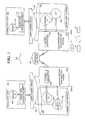
- FIG. 1is a simplified illustration of a data protection system 100 .
- Shown in FIG. 1are two sites; Site I, which is a production site, on the right, and Site II, which is a backup site, on the left.
- the production siteis the source side of system 100
- the backup siteis the target side of the system.
- the backup siteis responsible for replicating production site data. Additionally, the backup site enables rollback of Site I data to an earlier point in time, which may be used in the event of data corruption of a disaster, or alternatively in order to view or to access data from an earlier point in time.
- a failovermay be performed in the event of a disaster at the production site, or for other reasons.
- Site I or Site IIbehaves as a production site for a portion of stored data, and behaves simultaneously as a backup site for another portion of stored data.
- a portion of stored datais replicated to a backup site, and another portion is not.
- the production site and the backup sitemay be remote from one another, or they may both be situated at a common site, local to one another.
- Local data protectionhas the advantage of minimizing data lag between target and source, and remote data protection has the advantage is being robust in the event that a disaster occurs at the source side.
- the source and target sidescommunicate via a wide area network (WAN) 128 , although other types of networks are also adaptable for use.
- WANwide area network
- Each side of system 100includes three major components coupled via a storage area network (SAN); namely, (i) a storage system, (ii) a host computer, and (iii) a data protection appliance (DPA).
- the source side SANincludes a source host computer 104 , a source storage system 108 , and a source DPA 112 .
- the target side SANincludes a target host computer 116 , a target storage system 120 , and a target DPA 124 .
- a SANincludes one or more devices, referred to as “nodes”.
- a node in a SANmay be an “initiator” or a “target”, or both.
- An initiator nodeis a device that is able to initiate requests to one or more other devices; and a target node is a device that is able to reply to requests, such as small computer system interface (SCSI) commands, sent by an initiator node.
- a SANmay also include network switches, such as fiber channel switches.
- the communication links between each host computer and its corresponding storage systemmay be any appropriate medium suitable for data transfer, such as fiber communication channel links.
- the hostcommunicates with its corresponding storage system using small computer system interface (SCSI) commands.
- SCSIsmall computer system interface
- System 100includes source storage system 108 and target storage system 120 .
- Each storage systemincludes physical storage units for storing data, such as disks or arrays of disks.
- storage systems 108 and 120are target nodes.
- storage system 108exposes one or more logical units (LU) to which commands are issued.
- LUlogical units
- storage systems 108 and 120are SAN entities that provide multiple logical units for access by multiple SAN initiators.
- Logical unitsare a logical entity provided by a storage system, for accessing data stored in the storage system.
- a logical unitis identified by a unique logical unit number (LUN).
- LUNunique logical unit number
- storage system 108exposes a logical unit 136 , designated as LU A
- storage system 120exposes a logical unit 156 , designated as LU B.
- LU Bis used for replicating LU A.
- LU Bis generated as a copy of LU A.
- LU Bis configured so that its size is identical to the size of LU A.
- storage system 120serves as a backup for source side storage system 108 .
- some logical units of storage system 120may be used to back up logical units of storage system 108 , and other logical units of storage system 120 may be used for other purposes.
- there is symmetric replicationwhereby some logical units of storage system 108 are used for replicating logical units of storage system 120 , and other logical units of storage system 120 are used for replicating other logical units of storage system 108 .
- System 100includes a source side host computer 104 and a target side host computer 116 .
- a host computermay be one computer, or a plurality of computers, or a network of distributed computers, each computer may include inter alia a conventional CPU, volatile and non-volatile memory, a data bus, an I/O interface, a display interface and a network interface.
- a host computerruns at least one data processing application, such as a database application and an e-mail server.
- an operating system of a host computercreates a host device for each logical unit exposed by a storage system in the host computer SAN.
- a host deviceis a logical entity in a host computer, through which a host computer may access a logical unit.
- host device 104identifies LU A and generates a corresponding host device 140 , designated as Device A, through which it can access LU A.
- host computer 116identifies LU B and generates a corresponding device 160 , designated as Device B.
- host computer 104is a SAN initiator that issues I/O requests (write/read operations) through host device 140 to LU A using, for example, SCSI commands. Such requests are generally transmitted to LU A with an address that includes a specific device identifier, an offset within the device, and a data size. Offsets are generally aligned to 512 byte blocks.
- the average size of a write operation issued by host computer 104may be, for example, 10 kilobytes (KB); i.e., 20 blocks. For an I/O rate of 50 megabytes (MB) per second, this corresponds to approximately 5,000 write transactions per second.
- System 100includes two data protection appliances, a source side DPA 112 and a target side DPA 124 .
- a DPAperforms various data protection services, such as data replication of a storage system, and journaling of I/O requests issued by a host computer to source side storage system data.
- data protection servicessuch as data replication of a storage system, and journaling of I/O requests issued by a host computer to source side storage system data.
- a DPAmay also enable rollback of data to an earlier point in time, and processing of rolled back data at the target site.
- Each DPA 112 and 124is a computer that includes inter alia one or more conventional CPUs and internal memory.
- each DPAis a cluster of such computers.
- Use of a clusterensures that if a DPA computer is down, then the DPA functionality switches over to another computer.
- the DPA computers within a DPA clustercommunicate with one another using at least one communication link suitable for data transfer via fiber channel or IP based protocols, or such other transfer protocol.
- One computer from the DPA clusterserves as the DPA leader.
- the DPA cluster leadercoordinates between the computers in the cluster, and may also perform other tasks that require coordination between the computers, such as load balancing.
- DPA 112 and DPA 124are standalone devices integrated within a SAN.
- each of DPA 112 and DPA 124may be integrated into storage system 108 and storage system 120 , respectively, or integrated into host computer 104 and host computer 116 , respectively.
- Both DPAscommunicate with their respective host computers through communication lines such as fiber channels using, for example, SCSI commands.
- DPAs 112 and 124are configured to act as initiators in the SAN; i.e., they can issue I/O requests using, for example, SCSI commands, to access logical units on their respective storage systems. DPA 112 and DPA 124 are also configured with the necessary functionality to act as targets; i.e., to reply to I/O requests, such as SCSI commands, issued by other initiators in the SAN, including inter alia their respective host computers 104 and 116 . Being target nodes, DPA 112 and DPA 124 may dynamically expose or remove one or more logical units.
- Site I and Site IImay each behave simultaneously as a production site and a backup site for different logical units.
- DPA 112 and DPA 124may each behave as a source DPA for some logical units, and as a target DPA for other logical units, at the same time.
- host computer 104 and host computer 116include protection agents 144 and 164 , respectively.
- Protection agents 144 and 164intercept SCSI commands issued by their respective host computers, via host devices to logical units that are accessible to the host computers.
- a data protection agentmay act on an intercepted SCSI commands issued to a logical unit, in one of the following ways:
- a protection agentmay handle different SCSI commands, differently, according to the type of the command. For example, a SCSI command inquiring about the size of a certain logical unit may be sent directly to that logical unit, while a SCSI write command may be split and sent first to a DPA associated with the agent.
- a protection agentmay also change its behavior for handling SCSI commands, for example as a result of an instruction received from the DPA.
- the behavior of a protection agent for a certain host devicegenerally corresponds to the behavior of its associated DPA with respect to the logical unit of the host device.
- the associated protection agentsplits I/O requests issued by a host computer to the host device corresponding to that logical unit.
- the associated protection agentfails I/O requests issued by host computer to the host device corresponding to that logical unit.
- Protection agentsmay use any protocol suitable for data transfer within a SAN, such as fiber channel, or SCSI over fiber channel.
- the communicationmay be direct, or via a logical unit exposed by the DPA.
- protection agentscommunicate with their respective DPAs by sending SCSI commands over fiber channel.
- protection agents 144 and 164are drivers located in their respective host computers 104 and 116 .
- a protection agentmay also be located in a fiber channel switch, inside the storage system or in any other device situated in a data path between a host computer and a storage system.
- DPA 112acts as a source site DPA for LU A.
- protection agent 144is configured to act as a source side protection agent; i.e., as a splitter for host device A. Specifically, protection agent 144 replicates SCSI I/O requests. A replicated SCSI I/O request is sent to DPA 112 . After receiving an acknowledgement from DPA 124 , protection agent 144 then sends the SCSI I/O request to LU A. Only after receiving a second acknowledgement from storage system 108 will host computer 104 initiate another I/O request.
- DPA 112When DPA 112 receives a replicated SCSI write request from data protection agent 144 , DPA 112 transmits certain I/O information characterizing the write request, packaged as a “write transaction”, over WAN 128 to DPA 124 on the target side, for journaling and for incorporation within target storage system 120 .
- DPA 112may send its write transactions to DPA 124 using a variety of modes of transmission, including inter alia (i) a synchronous mode, (ii) an asynchronous mode, and (iii) a snapshot mode.
- DPA 112sends each write transaction to DPA 124 , receives back an acknowledgement from DPA 124 , and in turns sends an acknowledgement back to protection agent 144 .
- Protection agent 144waits until receipt of such acknowledgement before sending the SCSI write request to LU A.
- DPA 112sends an acknowledgement to protection agent 144 upon receipt of each I/O request, before receiving an acknowledgement back from DPA 124 .
- DPA 112receives several I/O requests and combines them into an aggregate “snapshot” of all write activity performed in the multiple I/O requests, and sends the snapshot to DPA 124 , for journaling and for incorporation in target storage system 120 .
- DPA 112also sends an acknowledgement to protection agent 144 upon receipt of each I/O request, before receiving an acknowledgement back from DPA 124 .
- DPA 124While in production mode, DPA 124 receives replicated data of LU A from DPA 112 , and performs journaling and writing to storage system 120 . When applying write operations to storage system 120 , DPA 124 acts as an initiator, and sends SCSI commands to LU B.
- DPA 124undoes the write transactions in the journal, so as to restore storage system 120 to the state it was at, at an earlier time.
- LU Bis used as a backup of LU A.
- host computer 116should not be sending I/O requests to LU B.
- protection agent 164acts as a target site protection agent for host Device B and fails I/O requests sent from host computer 116 to LU B through host Device B.
- target storage system 120exposes a logical unit 176 , referred to as a “journal LU”, for maintaining a history of write transactions made to LU B, referred to as a “journal”.
- journal LU 176may be striped over several logical units, or may reside within all of or a portion of another logical unit.
- DPA 124includes a journal processor 180 for managing the journal.
- Journal processor 180functions generally to manage the journal entries of LU B. Specifically, journal processor 180 (i) enters write transactions received by DPA 124 from DPA 112 into the journal, by writing them into the journal LU, (ii) applies the journal transactions to LU B, and (iii) updates the journal entries in the journal LU with undo information and removes already-applied transactions from the journal. As described below, with reference to FIGS. 2 and 3 A- 3 D, journal entries include four streams, two of which are written when write transaction are entered into the journal, and two of which are written when write transaction are applied and removed from the journal.
- FIG. 2is a simplified illustration of a write transaction 200 for a journal.
- the journalmay be used to provide an adaptor for access to storage 120 at the state it was in at any specified point in time. Since the journal contains the “undo” information necessary to rollback storage system 120 , data that was stored in specific memory locations at the specified point in time may be obtained by undoing write transactions that occurred subsequent to such point in time.
- Write transaction 200generally includes the following fields:
- time stampwhich is the date & time at which the transaction was received by source side DPA 112 ;
- a write sizewhich is the size of the data block
- journal LU 176a location in journal LU 176 where the data is entered
- Write transaction 200is transmitted from source side DPA 112 to target side DPA 124 .
- DPA 124records the write transaction 200 in four streams.
- a first streamreferred to as a DO stream, includes new data for writing in LU B.
- a second streamreferred to as an DO METADATA stream, includes metadata for the write transaction, such as an identifier, a date & time, a write size, a beginning address in LU B for writing the new data in, and a pointer to the offset in the do stream where the corresponding data is located.
- a third streamreferred to as an UNDO stream
- a fourth streamreferred to as an UNDO METADATA
- an identifiera date & time
- a write sizea beginning address in LU B where data was to be overwritten
- each of the four streamsholds a plurality of write transaction data.
- write transactionsare received dynamically by target DPA 124 , they are recorded at the end of the DO stream and the end of the DO METADATA stream, prior to committing the transaction.
- the various write transactionsare applied to LU B, prior to writing the new DO data into addresses within the storage system, the older data currently located in such addresses is recorded into the UNDO stream.
- journal entryBy recording old data, a journal entry can be used to “undo” a write transaction.
- old datais read from the UNDO stream in a reverse order, from the most recent data to the oldest data, for writing into addresses within LU B. Prior to writing the UNDO data into these addresses, the newer data residing in such addresses is recorded in the DO stream.
- the journal LUis partitioned into segments with a pre-defined size, such as 1 MB segments, with each segment identified by a counter.
- the collection of such segmentsforms a segment pool for the four journaling streams described hereinabove.
- Each such streamis structured as an ordered list of segments, into which the stream data is written, and includes two pointers—a beginning pointer that points to the first segment in the list and an end pointer that points to the last segment in the list.
- write transaction datais appended to the stream either at the end, for a forward direction, or at the beginning, for a backward direction.
- DPA 124As each write transaction is received by DPA 124 , its size is checked to determine if it can fit within available segments. If not, then one or more segments are chosen from the segment pool and appended to the stream's ordered list of segments.
- DO datais written into the DO stream, and the pointer to the appropriate first or last segment is updated. Freeing of segments in the ordered list is performed by simply changing the beginning or the end pointer. Freed segments are returned to the segment pool for re-use.
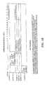
- journalingis thus advanced as indicated in TABLE I below.
- Step 1The new data is written at the end of the DO stream, assuming a forward write direction, and corresponding metadata is written at the end of the DO METADATA stream.
- Step 2Data is read from the beginning of the DO stream, and corresponding metadata is read from the beginning of the DO METADATA stream.
- Step 3Old data to be overwritten is read from LU B. The location and size of such old data is determined from the DO METADATA stream.
- Step 4The old data is written at the end of the UNDO stream, and corresponding metadata is written at the end of the UNDO METADATA stream.
- Step 5The new data read at Step 2 is written into LU B, and the beginning and end pointers of the DO and DO METADATA streams are moved appropriately.
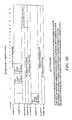
- Step 1Read the data and metadata from the end of the UNDO and UNDO METADATA streams.
- Step 2Read from LU B the data that is to be overwritten. The location and size of such data is determined from the UNDO METADATA stream.
- Step 3Write the data from Step 2 at the beginning of the DO stream, and update the DO METADATA stream accordingly.
- Step 4Write the data from Step 1 to LU B, and update the beginning and end pointers of the UNDO and UNDO metadata streams appropriately.
- a journal volumeincludes a plurality of segments from a segment pool, each segment including 20 data blocks.
- Stage #1Enter the three write transactions as journal entries in the journal LU.
- Stage #2Apply the first write transaction to LU B.
- Stage #3Apply the second write transaction to LU B.
- Stage #4Rollback the second write transaction, to recover data from an earlier point in time.
- the metadata corresponding to this transactionis written to the first block of Segment #2.
- the metadata corresponding to this transactionis written to the second block of Segment #2.
- the metadata corresponding to this transactionis written to the third block of Segment #2.
- the UNDO stream and the UNDO METADATA streamare empty.
- the journal and the four streams at the end of stage #1are illustrated in FIG. 3A .
- New data to be writtenis read from the journal LU at the offset and length indicated in the DO METADATA; namely, 15 blocks of data located in blocks 0 - 14 of journal volume Segment #1.
- old datais read from LU B at the offset and length indicated in the UNDO METADATA; namely, 15 blocks of data located in blocks 57 - 71 of LU B.
- the old datais then written into the UNDO stream in the journal LU, and the associated metadata is written into the UNDO METADATA stream in the journal LU.
- the UNDO datais written into the first 15 blocks of Segment #5, and the UNDO METADATA is written into the first block of Segment #6.
- journal LU Segment #1the new data that was read from blocks 0 - 14 of journal LU Segment #1 is written to blocks 57 - 71 of LU B.
- the beginning pointer for the DO streamis moved forward to block 15 of journal LU Segment #1, and the beginning pointer for the DO METADATA stream is moved forward to block 1 of journal LU Segment #2.
- the journal and the four streams at the end of stage #2are illustrated in FIG. 3B .
- 20 blocks of new dataare read from blocks 15 - 19 of journal LU Segment #1 and from blocks 0 - 14 of journal LU Segment #3.
- 20 blocks of old dataare read from blocks 87 - 106 of LU B.
- the old datais written to the UNDO stream in the last 5 blocks of journal LU Segment #5 and the first 15 blocks of journal LU Segment #7.
- the associated metadatais written to the UNDO METADATA stream in the second block of Segment #6.
- the list of segments in the UNDO streamincludes Segment #5 and Segment #7.
- the end pointer of the UNDO streamis moved to block 15 of Segment #7, and the end pointed of the UNDO METADATA stream is moved to block 2 of Segment #6.
- the 20 blocks of data from area (b)are read from LU B and written to the beginning of the DO stream.
- the end pointer for the DO streamis set to block 15 of Segment #8.
- the list of segments for the DO streamis changed to Segment #3, Segment #4 and Segment #8.
- the metadata associated with the 20 blocks from area (b)is written to block 3 of Segment #2, and the end pointer of the DO METADATA stream is advanced to block 4 of Segment #2.
- journalis thus used to rollback LU B to the state that it was in at a previous point in time.
- the journalis also used to selectively access data from LU B at such previous point in time, without necessarily performing a rollback. Selective access is useful for correcting one or more files that are currently corrupt, or for simply accessing old data.
- FIG. 4is a simplified flowchart of a data protection method corresponding to TABLE IV.
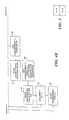
- FIG. 4is divided into four columns. The leftmost column indicates steps performed by source side protection agent 112 , the middle left column indicates steps performed by source side DPA 144 , the middle right column indicates steps performed by target side DPA 124 , and the rightmost column indicates steps performed by target side protection agent 164 .
- Source Side Intercept SCSI commands issued to LU A by Agent 144 source side host via Device A(step 404).
- Replicate write commands, and route write commands to DPA(steps 408 and 412). Wait for first acknowledgement, from DPA (step 416), and then route replicate I/O command to LU A (step 420). Wait for second acknowledgement, from storage system (step 424), and then process next intercepted SCSI command (step 404).
- Source Side Receive write command from agentstep 428).
- DPA 112Format write command as write transaction, and send to target DPA (step 428). In synchronous mode, wait for acknowledgement from target DPA (step 432), and then send acknowledgement to agent (step 436).
- Target Side Receive write transactionfrom source DPA (step DPA 124 444). Enter write transaction in journal DO and DO METADATA streams (step 444), and send back acknowledgement to source DPA (step 448).
- Process journal entriesby applying them to LU B, and enter undo information in UNDO and UNDO METADATA streams (step 440).
- Agent 164
- steps 432 and 436which do not have arrows connecting them, are not necessarily sequential. In synchronous mode these steps are sequential, but in asynchronous mode and in snapshot mode they are not sequential.
- DPA 112may send an acknowledgement to protection agent 144 before receiving an acknowledgement back from DPA 124 .
- steps performed by target side DPA 124include two non-sequential groups; namely, (i) step 440 , and (ii) steps 444 and 448 .
- Recovery modeis generally triggered as a result of a disaster at the source side.
- the source side datamay become corrupt, or may not exist at all.
- a usermay perform a failover operation by switching the roles of the production site and backup site.
- the original backup sitebecomes a current production site, and the original production site becomes a current backup site.
- recovery modecan be triggered without a failover, in order to access data from a previous point in time.
- target site DPA 124While in recovery mode, target site DPA 124 continues to receive new write transactions from DPA 112 and enter them at the ends of the DO and DO METADATA streams. However, unlike production mode behavior, DPA 124 stops applying journal entries received from DPA 112 to LU B. Instead, DPA 124 uses the UNDO stream of the journal to rollback LU B, as described hereinabove.
- protection agent 164stops failing I/O requests issued by host computer 160 and begins redirecting them to DPA 124 .
- the processing of data by host computer 160 during recovery modeis referred to as “target side processing (TSP)”.
- journal processor 180uses two additional data streams, referred to as TSP DO and TSP METADATA streams.
- TSP DOWhen a TSP write command is received by DPA 124 , it is entered at the end of the TSP DO stream and the end of the TSP DO METADATA stream. Since TSP writes relate to the state of LU B after the rollback is complete, the TSP DO stream writes are only applied to LU B after rollback is complete.
- Journal processor 180applies TSP writes to LU B in a way similar to the way it applies write transactions deceiver from DPA 112 ; namely, journal processor 180 maintains the undo information for each write applied to LU B, in TSP UNDO and TSP UNDO METADATA streams.
- DPA 124When TSP read commands are received by target site DPA 124 , DPA 124 returns the data to be read by identifying locations of the read command, and finding the most recent TSP write command or commands that were applied at these locations. The data is searched for (i) first in the TSP DO stream, and (ii) then in the journal UNDO data that was not yet applied to LU B and (iii) finally, if the data was not found in (i) and (ii), then the data is taken from LU B itself. In order to perform such a search efficiently, DPA 124 generates and stores in its memory a virtual image of the UNDO METADATA storage locations by using an efficient data structure, such as a binary search tree.
- an efficient data structuresuch as a binary search tree.
- TSP writes that were performed during the rollbackare applied to LU B, and DPA 124 begins applying TSP writes synchronously; i.e., TSP writes are applied to LU B when they are received by DPA 124 , without keeping them in the TSP DO stream.
- TSP writesare applied to LU B when they are received by DPA 124 , without keeping them in the TSP DO stream.
- a read commandis received after rollback is complete, it is sent directly to LU B instead of being redirected through DPA 124 .
- FIGS. 5A , 5 B, 6 A and 6 Bare simplified flowcharts of data protection methods corresponding to TABLES V and VI, respectively.
- FIGS. 5A , 5 B, 6 A and 6 Bare divided into four columns. The leftmost column indicates steps performed by target side protection agent 164 , the middle left column indicates steps performed by target side DPA 124 , the middle right column indicates steps performed by source side DPA 112 , and the rightmost column indicates steps performed by source side protection agent 144 .
- Target Side Intercept SCSI commands issued to LU B(step Agent 164 576). Redirect commands to DPA (step 580). Target Side Use UNDO stream of journal to roll back target DPA 124 storage system (step 540). Continue receiving write transactions from DPA 112 and enter these transactions into DO and DO METADATA streams without applying them to LU B (step 548). Enter TSP write transactions to TSP DO and TSP DO METADATA streams (step 564). Create a virtual image, to reply to read commands issued during the recovery process (step 572). Source Side As in production mode. DPA 112 Source Side As in production mode. Agent 144
- Target Side Intercept SCSI commands issued to LU B(step Agent 164 664). Redirect write transactions to DPA (step 672), and route read commands directly to LU B (step 680).
- Source SideAs in production mode.
- DPA 112Source Side As in production mode.
- Agent 144Redirect write transactions to DPA (step 672), and route read commands directly to LU B (step 680).
- Target Side Apply TSP write transactions to LU Bin the same DPA 124 manner that write transactions received from DPA 112 are applied in production mode; i.e
- the steps performed by target side DPA 124include three non-sequential groups; namely, (i) step 540 , (i) steps 548 and 552 , and (iii) steps 556 , 560 , 564 , 568 and 572 .
- target side DPAperforms three non-sequential groups of steps; namely, (i) step 640 , (ii) steps 644 and 648 , and (iii) steps 652 , 656 and 660 .
- FIG. 7is a simplified illustration of a time-line for tracking new processing of old data.
- FIG. 7illustrates journal processor 180 bringing the timeline back to a previous time, TOLD, and journal processor 180 applying TSP writes to bring the timeline forward from time TCURRENT to time TNEW.
- current data at time ( 1 )is rolled back to old data at time ( 2 ).
- the rolled back databecomes the image upon which target side processing advances to new data at time ( 3 ); i.e., the target side processing is applied to data ( 2 ) and not to data ( 1 ).
- the data at time ( 1 )is a common image for LU A and LU B at the same point in time, TCURRENT.
- the data at time ( 2 )is a common image for LU A and LU B at time TOLD.
- Rolled back data at time ( 2 )may be processed by TSP writes, while at the same time current data at time ( 1 ) is being processed by source side writes.
- the dataevolves along the path from time ( 2 ) to time ( 3 ) as it is processed by the target side, and along the path from time ( 2 ) to time ( 4 ) as it is processed by the source side.
- the data images at the source and target sides at time TNEWare thus different.
- the usermay (i) return to a normal production mode, or (ii) perform a failover by switching the replication direction.
- LU Bis rolled back to its state at time ( 2 ), and the write transactions along the path from ( 2 ) to ( 4 ) are applied to LU B, so as to bring LU B to the same image as LU A.
- LU Bis maintained at its state at time ( 3 ), and its data is copied from the target side to the source side so as to bring LU A to the same image as LU B.
- the state of the target side storageis substantially identical to the state that LU A was in at an earlier point in time.
- the state of LU Bis then in a new state that is different from the earlier state of LU A.
- DPA 124undoes the TSP writes that were written to LU B using the TSP undo stream, and then returns to its normal production mode and begins applying the data that was written into the DO stream.
- the DO streamincludes all write transactions that were undone while LU B was rolled back.
- the DO streamincludes new journal entries that were received from DPA 112 while DPA was in recovery mode.
- protection agent 164returns to its production mode by beginning to fail I/O requests issued by host 116 .
- the userwant to perform a failover; i.e., to make LU B in its current state a production LU and ensure that LU A is a copy of LU B.
- a failoveri.e., to make LU B in its current state a production LU and ensure that LU A is a copy of LU B.
- the write transactions in the DO stream that correspond to a point in time subsequent to the recovered point in timeare ignored.
- the TSP writes that were applied to LU B during the recovery processare applied to LU A.
- the replication directionchanges. Specifically, DPA 124 and protection agent 164 begin behaving in accordance with source site behavior, and DPA 112 and protection agent 144 begin behaving in accordance with target site behavior.
- the source sidein order to provide failover capability, in which the roles of the production site and the backup site are switched, it is desirable that the source side has the necessary system components to function as a target side, and vice versa.
- the source sideincludes its own journal LU 184 and journal processor 188 , as indicated with dotted lines in FIG. 1 .
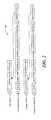
- FIG. 8is a simplified illustration of a 5-stage journaling process for continuous data replication.
- the five steps shown in FIG. 8correspond respectively to the five steps listed in TABLE I.
- FIG. 8only shows three meta-data elements; namely, a size, a journal address and a storage address.
- the meta-data in the DO METADATA and UNDO METADATA streamsincludes an ID, a time, and other attributes.
- the meta-data for each transactionis of a fixed size, typically 30 bytes.
- the raw datavaries in size, typically averaging around 10 KB per transaction.
- step 2may be skipped.
- FIG. 9is a simplified illustration of a 4-stage journaling process for continuous data replication, for use when an I/O data rate is low.
- the first step in FIG. 9copies the write transaction to the end of the DO stream and the end of the DO METADATA stream, as in the 5-stage journaling process.
- the 4-stage journaling processtakes advantage of the fact that the write transaction that was just received at the backup site is still resident in memory. For this write transaction, steps 3-5 are performed, as indicated in FIG. 9 .
- the write transactionis written into the end of a queue in memory.
- the queue in memoryis handled similar to the way the DO stream is handled; namely, each received write is appended to the end of the queue, and when a write transaction is distributed according to steps 3-5, a subsequent write transaction is taken from the beginning of the queue. Effectively, the queue corresponds to a cached DO stream.
- the 4-stage journaling processis used until the queue in memory is full, at which point the normal 5-stage journal processing is resumed. Also in the event of a disaster, the normal 5-stage journal processing is resumed. In order to resume the 5-stage journal processing, it is important to identify the last write in the DO stream that was written. As such, even during the 4-stage journal processing, the pointers to the first and last write transactions in the DO stream are updated.
- the normal 5-stage modemay be switched to a faster 3-stage mode whenever the DO stream reaches a large percentage of its maximum capacity, typically 80%.
- the faster 3-stage modeis switched back to the normal 5-stage mode whenever the DO stream is reduced to a smaller percentage of its maximum capacity, typically 75%.
- the 3-stage modeeliminates steps 3 and 4 from the normal mode; namely, the steps that record the UNDO information. As such, rollback of the backup storage unit to its state at the times of those transactions processed with the 3-stage mode is not possible.
- FIG. 10is a simplified illustration of a 3-stage journaling process for continuous data replication, for use when the DO stream is near its maximum capacity.
- One data replication strategyis the set of automated rules for controlling when a data replication system transitions between 5-stage, 4-stage and 3-stage journal processing.
- transitions from 5-stage to 3-stage journaling, and from 3-stage back to 5-stage journalingmay be controlled based on the current size of the DO stream.
- Transitions from 5-stage to 4-stage journalingmay be automated to occur when the beginning and end of the DO stream are close; and transitions from 4-stage back to 5-stage journaling may be automated to occur when the memory queue reaches its capacity.
- FIG. 11is a simplified state diagram of transitions between 5-stage, 4-stage and 3-stage journal processing. Shown in FIG. 11 are three nodes, representing each of the journaling processes, and directed edges between the nodes corresponding to rules that govern transitions therebetween. As shown in FIG. 11 , a 5-stage to 3-stage transition occurs when the size of the DO stream exceeds 80% of its allotted capacity, and a 3-stage to 5-stage transition occurs when the size of the DO stream falls under 75% of its allotted capacity. Similarly, a 5-stage to 4-stage transition occurs when the beginning and end of the DO stream are close; and a 4-stage to 5-stage transition occurs when the memory queue reaches its capacity.
- 4-stage journalingenables a data replication system to keep pace with higher I/O rates than can be handled when using 5-stage journaling. If the system is currently using 5-stage journaling and the I/O rate is higher than can be handled, a lag increases until the system necessarily transitions to the 3-stage journaling process. However, if the system can catch up with the lag, empty the DO stream and transition to a 4-stage journaling process, then the system can accommodate higher I/O rates before transitioning back to the 5-stage journaling process.
- FIG. 12is a simplified illustration of a variant of the three-stage journaling process shown in FIG. 10 .
- the alternative 3-stage journalingproceeds according to the last three stages of the 4-stage journaling process. That is, the stage of writing to the DO stream is skipped within 4-stage journaling, for the alternative embodiment of 3-stage journaling.
- the backup site DPA(element 124 of FIG. 1 ) can return an acknowledgement to the production site DPA (element 112 of FIG. 1 ) immediately after the first stage, when the write transaction is written to the DO stream.
- the backup site DPAmust wait until the write transaction is written to storage, before it can return an acknowledgement to the production site DPA. Since the last three stages of 4-stage journaling can be performed in a separate thread than the thread that performs the first stage, the alternative 3-stage journaling may result in a longer time lag between the source and target sites.
- a mapis generated to identify changes between a current volume state and the most updated state.
- the mapis used to enable signature testing only on locations where the volume is updated.
- a delta marker streamcontains the locations that may be different between the latest I/O data which arrived to the remote side (the current remote site) and the latest I/O data which arrived at the local side.
- the delta marking streamincludes metadata of the differences between the source side and the target side. For example, every I/O reaching the data protection appliance for the source 112 is written to the delta marking stream and data is freed from the delta marking stream when the data safely arrives at both the source volume of replication 108 and the remote journal 180 (e.g. DO stream). Specifically, during an initialization process no data is freed from the delta marking stream; and only when the initialization process is completed and I/O data has arrived to both local storage and the remote journal data is I/O data from the delta marking stream freed.
- the initialization processstarts by merging delta marking streams of the target and the source so that the delta marking stream includes a list of all different locations between local and remote sites. For example, a delta marking stream at the target might have data too if a user has accessed an image at the target site.
- the initialization processcreates one virtual disk out of all the available user volumes.
- the virtual spaceis divided into a selected number of portions depending upon the amount of data needed to be synchronized.
- a list of ‘dirty’ blocksis read from the delta marker stream that is relevant to the area currently being synchronized to enable creation of a dirty location data structure.
- the systembegins synchronizing units of data, where a unit of data is a constant amount of dirty data, e.g., a data that needs to be synchronized.
- the dirty location data structureprovides a list of dirty location until the amount of dirty location is equal to the unit size or until there is no data left.
- the systembegins a so-called ping pong process to synchronize the data.
- FIG. 13shows an exemplary synchronization environment in accordance with exemplary embodiments.
- a first volume 700such as a local volume (e.g., at the source side) is synchronized with a second volume 602 , such as a remote volume (e.g., at the target side).
- a pinger module 704 on the local appliance 112 and a ponger module 706 on the remote appliance 124examine data and selectively exchange information to efficiently perform initialization for making data in a remote site identical to data in a local site before replicating data in the remote volume.
- the local user volume 700interacts with the pinger module 704 , which is coupled to a WAN 707 .
- the remote user volume 702interacts with the ponger module 706 .
- the pinger module 704reads data from a part of the local user volume 700 , signs the data (i.e. calculates a hash function of the data), and transmits the signature 708 to the ponger module 706 .
- the ponger module 706reads from the same part of the remote user volume 702 , signs the data, and compares the signatures.
- the ponger module 706transmits to the pinger module 704 addresses 710 of the user volume blocks where data differs. If there are differences, the pinger module 704 again reads the data from the local user volume 700 and transmits the data 716 to the distributor 712 on the remote side through a transmitter 711 .
- the distributor 712processes initialization data from the pinger module 704 , which is written to the DO stream 750 while application data arriving in the local site is written to a temporary initialization stream 752 .
- the initialization stream 752 and the DO stream 750are united to create an initialization snapshot and then the data is written to the user volume 700 .
- a signatureis used only if calculation of data reduction shows that signature usage saves bandwidth.
- the signature replacement processcan be layered (i.e., calculate all the signature for the unit but at the beginning send only aggregated signatures from local to remote e.g., send a signature for every 256 blocks, then on the remote if the signature on all 256 block is different, check only for the block signature on one block level).
- signaturescan be used only if remote user volumes are updated with the latest image.
- Conventional systemsdo not use signatures if the remote copy is not updated to the last image.
- the remote copymay not be the latest for a number of reasons, such as a user being mounted on a point in time image at the remote site, a stoppage of the initialization process, and period in which the system could not handle I/Os in five phase distribution so that a gap is created between the latest image in the journal and the latest image in the user volume, as described in detail above.
- a dirty location mapis created to identify locations for which distribution from the DO stream to the UNDO stream has not yet taken place (or data written during logged access mode to the TSP stream).
- the dirty location mapis generated from the DO metadata stream and the TSP metadata stream.
- the systemcan begin using data signatures to compare data between local and remote volumes. Signatures are not used for locations in the dirty location map.
- the dirty location mapis updated with any I/O write operations.
- FIG. 15shows an example of a dirty location map generation.
- a first volume V 1has blocks 1 - 6 and a second volume V 2 has corresponding blocks 1 - 6 . It is determined that blocks 1 , 2 , and 3 of the local and remote volumes have differences that need to be addressed for initialization.
- the DO streamcontains a series of entries including an entry for block 2 , which has not yet been distributed.
- a corresponding entry for block 2is contained in the DO metadata stream.
- only block 2of differing blocks 1 - 3 , has an entry in the DO stream, and thus, signatures should not be used for block 2 .
- a dirty location map(DLM) is generated from the DO metadata stream. Only the entry for block 2 is set for blocks 1 - 6 of the volumes since block 2 is the only block contained in the DO metadata stream. In this example, a logical ONE is set in the dirty location map DLM for locations having entries in the DO stream.
- blocks 1 , 2 , and 3were found to have differences to be addressed during initialization.
- Block 2has an entry in the DO stream, which is reflected in the dirty location bit map DLM.
- a data signature for block 2should not be sent.
- data signaturescan be sent for blocks 1 and 3 .
- FIG. 16shows an exemplary process, an initialization process 790 , for implementing selective signature transmission for initialization in a continuous data protection system in accordance with exemplary embodiments described herein.
- a process step 800the initialization process 790 begins to synchronize first and second volumes from a local (source) and a remote (target) sides.
- process step 802differences between blocks in a first volume and corresponding blocks in a second volume are identified.
- process step 804a data stream containing data that has not been distributed to/from the data volumes is examined to identify locations for data distribution. In an exemplary embodiment, the DO metadata stream is examined to identify the locations.
- a dirty location mapis created in which locations contained in the DO metadata stream are flagged.
- the dirty location mapprovides a bitmap where each bit corresponds to block. In other embodiments, a bit corresponds to a number of disk blocks.
- the dirty location mapis used such that for flagged locations data signatures are not sent during the initialization process. Data signatures can be used for non-flagged locations.
- data signaturesare sent for locations not flagged in the dirty location map as part of the volume synchronization process.
- the initialization processcan occur while a user is currently mounting an old point in time.
- datais distributed from the undo stream to the DO stream, this process can happen while the initialization process is actually running, meaning, the do stream actually grows and contains more data during the initialization.
- the user volumegets less updated and the system needs to add the locations to the dirty location bitmap, so every redo data written to the DO stream updates the bitmap.
- a delta marker streamis a stream of metadata which includes the locations that may be different between the production volume (also described herein as the source side volume) and the replication volume (also described herein as the target side volume) in case of a disaster (e.g., DPA failure, cable failure, WAN failure, temporary storage failure, and so forth).
- DPADPA failure
- cable failurecable failure
- WAN failuretemporary storage failure
- I/Os completed to the source volumewhich have not yet been applied to the replication journal 176 and I/Os applied to the replication journal 176 and have not yet completed to the production volume 108 .
- the delta marker streamis stored persistently on a storage LUN (e.g., DMS 1030 in FIG. 17 ).
- a storage LUNe.g., DMS 1030 in FIG. 17 .
- a first methodis when the DPA sends an acknowledgement message to the protection agent only after the metadata of the I/O is written to the delta marking stream.
- Synchronous markingin general reduces the performance of the system 1000 .
- a second methodis when a cache of the metadata of the latest transactions is held and the cache is flushed periodically.
- asynchronous markingis also problematic. For example, if a DPA fails, the data in the cache is lost.
- a common solutionis to keep a super set of the DPA delta marking cache in the splitter memory (e.g., protection agent); however this complicates the splitter code and the splitter code must be modified each time for newer platforms.
- Another problem with the splitter holding the metadatais that is some cases the splitter and a virtual DPA may actually run on the same physical hardware thus the splitter and the virtual DPA may fail at the same time.
- Described hereinis a process to mirror metadata not yet committed to the delta marking stream. Rather than storing the uncommitted metadata at a protection agent; the uncommitted metadata is stored in a cache (e.g., one of caches 1040 a - 1040 c in FIG. 17 ) at another DPA, for example. With this approach, a protection agent is simplified. While the description focuses on mirroring uncommitted metadata within a data protection environment, the techniques described herein may be used in any data environment to mirror data.
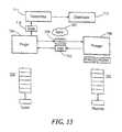
- a data protection system 1000includes a source-side host 104 ′ similar in functionality to the source-side host 104 , for example, but with a less complex protection agent 1010 (e.g., the protection agent 1010 may run on the host on a switch on the storage array or on any other device on the data path).
- the system 1000also includes a source side storage 108 ′, similar to source-side storage 108 , which includes a persistent delta marking stream (DMS) 1030 (e.g., the delta marker stream (DMS) resides on a LUN in the storage volume).
- DMSpersistent delta marking stream
- the data protection system 1000also includes a DPA 112 a similar in functionality to the DPA 112 , for example and includes a journal processor 188 and a mirroring component 1020 used to mirror uncommitted metadata.
- the uncommitted metadatarefers to the metadata for the delta marking stream not yet moved to the persistent storage (DMS 1030 ) and represents the differences in the I/O data between the target and the source side storage.
- the data protection system 1000further includes a cluster of DPAs which includes the DPA 112 a as well as a DPA 112 b and a DPA 112 c . In other examples, there may be two or more than three DPAs.
- Each DPAincludes a cache to store mirrored metadata (e.g., DPA 112 a includes a cache 1040 a , DPA 112 b includes a cache 1040 b and DPA 112 c includes a cache 1040 c ).
- the DPAwill choose a mirror DPA on the same production site which will be used to mirror the uncommitted metadata.
- DPA 112 amay choose DPA 112 b or 112 c
- the DPA 112 bmay choose DPA 112 a or DPA 112 c and so forth.
- cache 1040 astores uncommitted metadata for DPA 112 a but also serves to minor uncommitted metadata from another DPA in the cluster.
- each DPAhas a cache to store its own respective uncommitted metadata and to store mirrored uncommitted metadata from at least one other DPA, one of ordinary skill in the art may clearly separate the cache 1040 into multiple sub-caches with each sub-cache dedicated to at least one DPA.
- the description hereinwill describe the DPA 112 a mirroring on the DPA 112 b .
- the mirroring mechanismmirrors the uncommitted metadata arriving from the DPA 112 a to the DPA 112 b .
- This mirroring protocolassures that if the DPA 112 a fails, the DPA 112 b will have the uncommitted metadata for DPA 112 a stored in its cache 1040 b.
- the metadata mirroring mechanismincludes at least three different modes of operation: a fragile mode, a minor mode and a stable mode.
- a minor modemeans that the uncommitted metadata is mirrored, for example, at another DPA 112 b - 112 c .
- the fragile modemeans that there is no mirroring (e.g., no place to minor the uncommitted metadata). Any failure of the DPA 112 a during the fragile mode will require that the system 1000 perform a complete sweep of the data (since the uncommitted metadata, which is only in the memory of DPA 112 a before the failure, is completely lost).
- the stable modemeans that the system 1000 has all of its uncommitted metadata moved into the persistent DMS 1030 . No new metadata I/Os can be received at the DPA 112 a and the DPA 112 a will fail any new I/Os.
- the protection agent 1010needs only to perform one of the following in the event the DPA 112 a fails:
- implementing a protection agentwhich tracks only I/Os that fail to the DPA 112 a is significantly easier than a protection agent which has to hold the uncommitted metadata of the delta marking stream.
- a protection agente.g., splitter
- implementationis easier to achieve than creating a new splitter (e.g., protection agent) for each new data protection system, and a general mirroring system can be changed to a splitter with no significant effort.
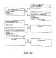
- one example of a process to mirror the uncommitted metadata between two DPAsis a process 1100 .
- Initial processingis performed ( 1102 ).
- a connectionis established between the DPA 112 a and the DPA 112 b and a session ID is opened.
- the data protection agent 1010is also notified to send I/Os.
- Metadata of the I/Ois received at the DPA 112 a ( 1106 ).
- the DPA 112 adetermines if mirroring is activated (e.g., in a mirroring mode) ( 1110 ).
- the DPA 112 awill send an acknowledgement to the protection agent 1010 at the host 104 ′ using a SCSI transfer ready command ( 1140 ) and the protection agent 1010 will be able to complete sending the I/O to the DPA 112 a.
- the uncommitted metadatais put in a cache 1040 a and the I/O is handled (i.e., sent to a remote DPA 124 and so forth) ( 1150 ).
- the host 104starts sending an I/O to the storage 108
- the protection agent 1010intercepts the I/O and sends the I/O to the DPA 112 a .
- the protection agentsends the I/O to storage 108 .
- the uncommitted metadata in the cache 1040 ais periodically moved to the persistent DMS 1030 .
- FIGS. 19A and 19Bdescribes examples of processes (e.g., processes 1200 and 1250 ) used in processing block 1150 .
- the uncommitted metadatais received at the DPA 112 a ( 1202 ) and stored in its cache 1040 a .
- the DPA 112 adetermines if the cache 1040 a reaches a certain size (n elements) ( 1206 ) or a certain time has elapsed (m seconds) ( 1210 ) and if either occurs moves the uncommitted metadata to the DMS 1030 .
- An acknowledgement messageis received from the remote DPA 124 that data has moved to the journal up to I/O with metadata ID x ( 1252 ).
- the data protection agent 1010is requested to synchronize storage ( 1254 ).
- Process 1250waits for local storage to be synchronized ( 1256 ). The synchronization is confirmed when all I/Os currently open from the protection agent 1010 are flushed to local storage. If synchronized, the metadata from delta marking stream until ID x is removed ( 1260 ).
- the I/Osare sent from the protection agent 1010 to the DPA 112 a using a SCSI write command. If mirroring is activated, the metadata received in the CDB of the SCSI write command is sent to the mirror DPA 112 b ( 1120 ). In one example, the mirroring information is send by a SCSI command descriptor block (CDB).
- CDBSCSI command descriptor block
- Process 1100determines whether the metadata transfer is successful ( 1130 ). For example, a SCSI status is received from the DPA 112 b at the DPA 112 a that the metadata arrived successfully.
- the DPA 112 awill send an acknowledgement to the protection agent 1010 using a SCSI transfer ready command ( 1140 ) and the protection agent 1010 will be able to complete sending the I/O to the DPA 112 a ( 1150 ).
- the system 1000is mirroring (e.g., sending uncommitted metadata to the mirror DPA 112 b ) and the mirroring fails (metadata transfer is not successful as determined by the processing block 1130 ), there are at least two options depending on the user configuration.
- the system 1000will write that it is currently in the fragile mode and will store the state to a persistent storage synchronously (meaning before letting any I/Os continue), then perform processing blocks 1140 and 1150 as described previously. If writing the fragile mode to the persistent storage fails then all open I/Os are failed ( 1172 ).
- Process 1300receives a command to perform mirror handling ( 1302 ).
- the DPA 112 areceives a request to perform mirror handling.
- the uncommitted metadatais received at the DPA 112 b ( 1304 ) and put in a basket (not shown) in the cache 1040 b ( 1306 ).
- a basket systemis a list of vectors or a list of lists. The current basket is the last vector/list in the list. New metadata is inserted to the end of the last vector/list. A basket is closed by adding another empty vector/list to the end of the list so that new I/Os will enter a new basket.
- Process 1300determines if an amount of time has expired ( 1310 ). For example, DPA 112 b determines if a specified amount of time (e.g., every 10 seconds) has elapsed using a timer (not shown). In other example, the process 1300 may determine if a specified amount of metadata elements has arrived.
- a specified amount of timee.g., every 10 seconds
- a timernot shown
- the process 1300may determine if a specified amount of metadata elements has arrived.
- the DPA 112 bcontinues to receive metadata from the DPA 112 a . If the amount of time has elapsed, a new basket is opened ( 1320 ) and the I/O of the metadata enters the new vector. The minor DPA 112 b sends a sync delta marker request to the original DPA 112 a ( 1330 ). When the original DPA 112 a gets the sync delta marker request it will make sure all the pending I/Os to the DPA 112 a are moved to the DMS 1030 and only then return an acknowledgement message to the mirror DPA 112 b .
- the minor DPA 112 bcan erase the closed basket in the cache 1040 b since all the relevant metadata was already moved to the DMS 1030 ( 1350 ).
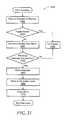
- an example of a process to recover mirrored metadatais a process 1400 .
- the process 1400is used if the production DPA 112 a fails, the replication task will restart at one of the available DPAs (or if DPA 112 a recovers it may start on DPA 112 a ).
- the process 1400will return all the metadata which was not moved to the DMS 1030 .
- a requestis received to recover mirrored metadata ( 1402 ).
- the mirroring component 1020receives a request to recover metadata stored at the cache 1040 b .
- the process 1400determines if the system 1000 is in the fragile mode ( 1410 ).
- the mirroring component 1020determines if the system 1000 is in the fragile mode.
- a full-sweepis performed ( 1450 ).
- a full sweepmeans it is not known which locations are suspected as being different between the source and the target.
- the system 1000rescans all the data, which is a long process.
- the full sweepis done by adding all the volumes in a consistency group as dirty from block 0 to the end of the volume, to the DMS 1030 .
- the mirrored metadatais acquired ( 1420 ).
- the mirrored metadatais retrieved from the cache 1040 b in the mirror DPA 112 b .
- the process 1400determines if the metadata has been received successfully (e.g., verifying meta data is also from the correct session) ( 1440 ).
- the mirroring component 1020determines if the metadata has been received successfully. If the metadata has not been received successfully, a full-sweep is performed ( 1450 ).
- the metadatais moved ( 1460 ) (i.e., written to the persistent delta marking stream), the system 1000 moves to the stable mode ( 1464 ) and the mirror is closed ( 1470 ) so that a new minor may be established (as described in FIG. 18 ).
- the new mirrormay be on a different DPA because the new replication process may run on the same DPA ( 112 b ) as the old mirroring process, thus the minor must run on a different DPA.
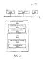
- FIG. 22is an example of a computer 2000 , which may be used to execute all or part of the processes 1100 , 1200 , 1250 , 1300 and 1400 .
- Computer 2000includes a processor 2022 , a volatile memory 2024 , a non-volatile memory 2026 (e.g., hard disk), for example, and a user interface 2028 (e.g., a mouse, a keyboard, a touch screen and so forth).
- a processor 2022includes a processor 2022 , a volatile memory 2024 , a non-volatile memory 2026 (e.g., hard disk), for example, and a user interface 2028 (e.g., a mouse, a keyboard, a touch screen and so forth).
- a user interface 2028e.g., a mouse, a keyboard, a touch screen and so forth.
- Non-volatile memory 2026includes an operating system 2036 ; data 2038 including a delta marking stream 2040 and journal data 2042 including a DO stream, an UNDO stream, a DO METADATA stream, an UNDO METADATA stream and an initialization stream; and computer instructions 2034 which are executed out of volatile memory 2024 to perform all or part of processes.
- the processes described hereinare not limited to use with the hardware and software of FIG. 22 ; they may find applicability in any computing or processing environment and with any type of machine or set of machines that is capable of running a computer program.
- the processesmay be implemented in hardware, software, or a combination of the two.
- the processesmay be implemented in computer programs executed on programmable computers/machines that each includes a processor, a storage medium or other article of manufacture that is readable by the processor (including volatile and non-volatile memory and/or storage elements), at least one input device, and one or more output devices.
- Program codemay be applied to data entered using an input device to perform the processes 1100 , 1200 , 1250 , 1300 and 1400 , for example, and to generate output information.
- the processes 1100 , 1200 , 1250 , 1300 and 1400 described hereinare not limited to the specific embodiments described herein.
- the processesare not limited to the specific processing order of the process blocks in FIGS. 18 to 21 . Rather, any of the process blocks of FIGS. 18 to 21 may be re-ordered, combined or removed, performed in parallel or in serial, as necessary, to achieve the results set forth above.
- Process blocks in FIGS. 18 to 21 associated with implementing the systemmay be performed by one or more programmable processors executing one or more computer programs to perform the functions of the system. All or part of the system may be implemented as, special purpose logic circuitry (e.g., an FPGA (field programmable gate array) and/or an ASIC (application-specific integrated circuit)).
- special purpose logic circuitrye.g., an FPGA (field programmable gate array) and/or an ASIC (application-specific integrated circuit)
Landscapes
- Engineering & Computer Science (AREA)
- Theoretical Computer Science (AREA)
- Quality & Reliability (AREA)
- Physics & Mathematics (AREA)
- General Engineering & Computer Science (AREA)
- General Physics & Mathematics (AREA)
- Information Retrieval, Db Structures And Fs Structures Therefor (AREA)
Abstract
Description
| TABLE I |
| Entering a write transaction in the |
| Step |
| 1 | The new data is written at the end of the DO stream, assuming a |
| forward write direction, and corresponding metadata is written | |
| at the end of the DO METADATA stream. | |
| Data is read from the beginning of the DO stream, and corresponding | |
| metadata is read from the beginning of the DO METADATA stream. | |
| Old data to be overwritten is read from LU B. The location and size | |
| of such old data is determined from the DO METADATA stream. | |
| The old data is written at the end of the UNDO stream, and | |
| corresponding metadata is written at the end of the | |
| UNDO METADATA stream. | |
| The new data read at | |
| beginning and end pointers of the DO and DO METADATA | |
| streams are moved appropriately. | |
| TABLE II |
| Undoing a write transaction in the |
| Step |
| 1 | Read the data and metadata from the end of the UNDO and UNDO |
| METADATA streams. | |
| Read from LU B the data that is to be overwritten. The location and | |
| size of such data is determined from the UNDO METADATA stream. | |
| Write the data from | |
| update the DO METADATA stream accordingly. | |
| Write the data from | |
| end pointers of the UNDO and UNDO metadata | |
| streams appropriately. | |
| TABLE III |
| Example Write Transactions |
| Write | LU B | ||||
| ID | Time | location | Length | ||
| 1 | Dec. 3, 2005 | 15 | Segment | 1, | |
| 10:00:00.00 | offset 57 blocks | offset 0 | |||
| 2 | Dec. 3, 2005 | 20 | Segment | 1, | |
| 10:00:00.05 | offset 87 blocks | offset 15 | |||
| 3 | Dec. 3, 2005 | 20 | Segment | 3, | |
| 10:00:00.18 | offset 12 blocks | Offset 15 | |||
| TABLE IV |
| Normal Production Mode Functionality |
| System | |
| Component | Behavior |
| Source Side | Intercept SCSI commands issued to LU A by |
| source side host via Device A (step 404). Replicate | |
| write commands, and route write commands to DPA | |
| ( | |
| from DPA (step 416), and then route replicate I/O | |
| command to LU A (step 420). Wait for second | |
| acknowledgement, from storage system (step 424), and | |
| then process next intercepted SCSI command (step 404). | |
| Source Side | Receive write command from agent (step 428). |
| Format write command as write transaction, and send to | |
| target DPA (step 428). In synchronous mode, wait for | |
| acknowledgement from target DPA (step 432), | |
| and then send acknowledgement to agent (step 436). | |
| In asynchronous mode and in snapshot mode, send | |
| acknowledgement to agent without waiting for | |
| acknowledgement from target DPA (step 436). | |
| Target Side | Receive write transaction from source DPA (step |
| 444). Enter write transaction in journal DO and DO | |
| METADATA streams (step 444), and send back | |
| acknowledgement to source DPA (step 448). Process | |
| journal entries by applying them to LU B, | |
| and enter undo information in UNDO and | |
| UNDO METADATA streams (step 440). | |
| Target Side | Fail SCSI commands issued to LU B (step 452). |
| TABLE V |
| Recovery Functionality prior to Completion of Rollback |
| System | |
| Component | Behavior |
| Target Side | Intercept SCSI commands issued to LU B ( |
| Agent | |
| 164 | 576). Redirect commands to DPA (step 580). |
| Target Side | Use UNDO stream of journal to roll back |
| DPA | |
| 124 | storage system (step 540). Continue receiving write |
| transactions from | |
| into DO and DO METADATA streams without applying | |
| them to LU B (step 548). Enter TSP write transactions to | |
| TSP DO and TSP DO METADATA streams (step 564). | |
| Create a virtual image, to reply to read | |
| commands issued during the recovery process (step 572). | |
| Source Side | As in production mode. |
| Source Side | As in production mode. |
| TABLE VI |
| Recovery Functionality after Completion of Rollback |
| System | |
| Component | Behavior |
| Target Side | Intercept SCSI commands issued to LU B ( |
| Agent | |
| 164 | 664). Redirect write transactions to DPA (step 672), |
| and route read commands directly to LU B (step 680). | |
| Target Side | Apply TSP write transactions to LU B, in the |
| DPA | |
| 124 | manner that write transactions received from |
| applied in production mode; i.e., by entering data into TSP | |
| UNDO and TSP UNDO METADATA streams (step 640). | |
| Enter DO information and write transactions received | |
| from | |
| without applying them to LU B (step 644). Apply TSP | |
| write transactions to LU B as they are received (step 656). | |
| Source Side | As in production mode. |
| Source Side | As in production mode. |
| TABLE VII |
| Pros and Cons of Journaling Processes |
| Journaling Process | Pros | Cons |
| 3-Stage Journaling | Fastest replication time | Long time to recover to |
| current time | ||
| 4-Stage Journaling | Moderate replication time; | Only able to be used as |
| Full data recovery capability | long as the beginning | |
| and the end of the | ||
| DO stream are close | ||
| 5-Stage Journaling | Full data recovery capability | Slowest replication time |
- 1. Complete the IOs that failed to the
DPA 112aand track the locations that changed in the splitter memory or - 2. Fail the I/Os.
- 1. Complete the IOs that failed to the
Claims (19)
Priority Applications (1)
| Application Number | Priority Date | Filing Date | Title |
|---|---|---|---|
| US13/541,198US8438135B1 (en) | 2010-06-18 | 2012-07-03 | Mirroring metadata in a continuous data protection environment |
Applications Claiming Priority (2)
| Application Number | Priority Date | Filing Date | Title |
|---|---|---|---|
| US12/818,236US8271447B1 (en) | 2010-06-18 | 2010-06-18 | Mirroring metadata in a continuous data protection environment |
| US13/541,198US8438135B1 (en) | 2010-06-18 | 2012-07-03 | Mirroring metadata in a continuous data protection environment |
Related Parent Applications (1)
| Application Number | Title | Priority Date | Filing Date |
|---|---|---|---|
| US12/818,236ContinuationUS8271447B1 (en) | 2010-06-18 | 2010-06-18 | Mirroring metadata in a continuous data protection environment |
Publications (1)
| Publication Number | Publication Date |
|---|---|
| US8438135B1true US8438135B1 (en) | 2013-05-07 |
Family
ID=46800814
Family Applications (2)
| Application Number | Title | Priority Date | Filing Date |
|---|---|---|---|
| US12/818,236Active2030-11-23US8271447B1 (en) | 2010-06-18 | 2010-06-18 | Mirroring metadata in a continuous data protection environment |
| US13/541,198ActiveUS8438135B1 (en) | 2010-06-18 | 2012-07-03 | Mirroring metadata in a continuous data protection environment |
Family Applications Before (1)
| Application Number | Title | Priority Date | Filing Date |
|---|---|---|---|
| US12/818,236Active2030-11-23US8271447B1 (en) | 2010-06-18 | 2010-06-18 | Mirroring metadata in a continuous data protection environment |
Country Status (1)
| Country | Link |
|---|---|
| US (2) | US8271447B1 (en) |
Cited By (90)
| Publication number | Priority date | Publication date | Assignee | Title |
|---|---|---|---|---|
| US9026696B1 (en) | 2010-09-29 | 2015-05-05 | Emc Corporation | Using I/O track information for continuous push with splitter for storage device |
| US9069709B1 (en) | 2013-06-24 | 2015-06-30 | Emc International Company | Dynamic granularity in data replication |
| US9081842B1 (en) | 2013-03-15 | 2015-07-14 | Emc Corporation | Synchronous and asymmetric asynchronous active-active-active data access |
| US9087112B1 (en) | 2013-06-24 | 2015-07-21 | Emc International Company | Consistency across snapshot shipping and continuous replication |
| US9087008B1 (en) | 2013-06-24 | 2015-07-21 | Emc International Company | Replicating a volume using snapshots |
| US9110914B1 (en) | 2013-03-14 | 2015-08-18 | Emc Corporation | Continuous data protection using deduplication-based storage |
| US9146878B1 (en) | 2013-06-25 | 2015-09-29 | Emc Corporation | Storage recovery from total cache loss using journal-based replication |
| US9152814B1 (en) | 2010-03-15 | 2015-10-06 | Emc International Company | Writing and reading encrypted data using time-based encryption keys |
| US9152339B1 (en) | 2013-03-15 | 2015-10-06 | Emc Corporation | Synchronization of asymmetric active-active, asynchronously-protected storage |
| US9158630B1 (en) | 2013-12-19 | 2015-10-13 | Emc Corporation | Testing integrity of replicated storage |
| US9189339B1 (en) | 2014-03-28 | 2015-11-17 | Emc Corporation | Replication of a virtual distributed volume with virtual machine granualarity |
| US9223659B1 (en) | 2012-06-28 | 2015-12-29 | Emc International Company | Generating and accessing a virtual volume snapshot in a continuous data protection system |
| US9244997B1 (en) | 2013-03-15 | 2016-01-26 | Emc Corporation | Asymmetric active-active access of asynchronously-protected data storage |
| US9256605B1 (en) | 2011-08-03 | 2016-02-09 | Emc Corporation | Reading and writing to an unexposed device |
| US9274718B1 (en) | 2014-06-20 | 2016-03-01 | Emc Corporation | Migration in replication system |
| US9286052B1 (en) | 2011-09-15 | 2016-03-15 | Emc Corporation | Upgrading software on a pair of nodes in a clustered environment |
| US9336094B1 (en) | 2012-09-13 | 2016-05-10 | Emc International Company | Scaleout replication of an application |
| US9367260B1 (en) | 2013-12-13 | 2016-06-14 | Emc Corporation | Dynamic replication system |
| US9383937B1 (en) | 2013-03-14 | 2016-07-05 | Emc Corporation | Journal tiering in a continuous data protection system using deduplication-based storage |
| US9405765B1 (en) | 2013-12-17 | 2016-08-02 | Emc Corporation | Replication of virtual machines |
| US9405481B1 (en) | 2014-12-17 | 2016-08-02 | Emc Corporation | Replicating using volume multiplexing with consistency group file |
| US9411535B1 (en) | 2015-03-27 | 2016-08-09 | Emc Corporation | Accessing multiple virtual devices |
| US9501542B1 (en) | 2008-03-11 | 2016-11-22 | Emc Corporation | Methods and apparatus for volume synchronization |
| US9529885B1 (en) | 2014-09-29 | 2016-12-27 | EMC IP Holding Company LLC | Maintaining consistent point-in-time in asynchronous replication during virtual machine relocation |
| US9557921B1 (en) | 2015-03-26 | 2017-01-31 | EMC IP Holding Company LLC | Virtual volume converter |
| US9600377B1 (en) | 2014-12-03 | 2017-03-21 | EMC IP Holding Company LLC | Providing data protection using point-in-time images from multiple types of storage devices |
| US9619543B1 (en) | 2014-06-23 | 2017-04-11 | EMC IP Holding Company LLC | Replicating in virtual desktop infrastructure |
| US9632881B1 (en) | 2015-03-24 | 2017-04-25 | EMC IP Holding Company LLC | Replication of a virtual distributed volume |
| US9665305B1 (en) | 2015-06-26 | 2017-05-30 | EMC IP Holding Company LLC | Tiering data between two deduplication devices |
| US9678680B1 (en) | 2015-03-30 | 2017-06-13 | EMC IP Holding Company LLC | Forming a protection domain in a storage architecture |
| US9684576B1 (en) | 2015-12-21 | 2017-06-20 | EMC IP Holding Company LLC | Replication using a virtual distributed volume |
| US9696939B1 (en) | 2013-03-14 | 2017-07-04 | EMC IP Holding Company LLC | Replicating data using deduplication-based arrays using network-based replication |
| US9910735B1 (en) | 2016-03-30 | 2018-03-06 | EMC IP Holding Company LLC | Generating an application-consistent snapshot |
| US9910621B1 (en) | 2014-09-29 | 2018-03-06 | EMC IP Holding Company LLC | Backlogging I/O metadata utilizing counters to monitor write acknowledgements and no acknowledgements |
| US10019194B1 (en) | 2016-09-23 | 2018-07-10 | EMC IP Holding Company LLC | Eventually consistent synchronous data replication in a storage system |
| US10031703B1 (en) | 2013-12-31 | 2018-07-24 | Emc Corporation | Extent-based tiering for virtual storage using full LUNs |
| US10042751B1 (en) | 2015-09-30 | 2018-08-07 | EMC IP Holding Company LLC | Method and system for multi-tier all-flash array |
| US10055148B1 (en) | 2015-12-22 | 2018-08-21 | EMC IP Holding Company LLC | Storing application data as an enhanced copy |
| US10061666B1 (en) | 2011-12-30 | 2018-08-28 | Emc International Company | Method and apparatus for adding a director to storage with network-based replication without data resynchronization |
| US10067837B1 (en) | 2015-12-28 | 2018-09-04 | EMC IP Holding Company LLC | Continuous data protection with cloud resources |
| US10078459B1 (en) | 2016-09-26 | 2018-09-18 | EMC IP Holding Company LLC | Ransomware detection using I/O patterns |
| US10082980B1 (en) | 2014-06-20 | 2018-09-25 | EMC IP Holding Company LLC | Migration of snapshot in replication system using a log |
| US10101943B1 (en) | 2014-09-25 | 2018-10-16 | EMC IP Holding Company LLC | Realigning data in replication system |
| US10108356B1 (en) | 2016-03-25 | 2018-10-23 | EMC IP Holding Company LLC | Determining data to store in retention storage |
| US10114581B1 (en) | 2016-12-27 | 2018-10-30 | EMC IP Holding Company LLC | Creating a virtual access point in time on an object based journal replication |
| US10133874B1 (en) | 2015-12-28 | 2018-11-20 | EMC IP Holding Company LLC | Performing snapshot replication on a storage system not configured to support snapshot replication |
| US10140039B1 (en) | 2016-12-15 | 2018-11-27 | EMC IP Holding Company LLC | I/O alignment for continuous replication in a storage system |
| US10146961B1 (en) | 2016-09-23 | 2018-12-04 | EMC IP Holding Company LLC | Encrypting replication journals in a storage system |
| US10152267B1 (en) | 2016-03-30 | 2018-12-11 | Emc Corporation | Replication data pull |
| US10191687B1 (en) | 2016-12-15 | 2019-01-29 | EMC IP Holding Company LLC | Adaptive snap-based replication in a storage system |
| US10210073B1 (en) | 2016-09-23 | 2019-02-19 | EMC IP Holding Company, LLC | Real time debugging of production replicated data with data obfuscation in a storage system |
| US10223023B1 (en) | 2016-09-26 | 2019-03-05 | EMC IP Holding Company LLC | Bandwidth reduction for multi-level data replication |
| US10229006B1 (en) | 2015-12-28 | 2019-03-12 | EMC IP Holding Company LLC | Providing continuous data protection on a storage array configured to generate snapshots |
| US10235064B1 (en) | 2016-12-27 | 2019-03-19 | EMC IP Holding Company LLC | Optimized data replication using special NVME protocol and running in a friendly zone of storage array |
| US10235088B1 (en) | 2016-03-30 | 2019-03-19 | EMC IP Holding Company LLC | Global replication policy for multi-copy replication |
| US10235145B1 (en) | 2012-09-13 | 2019-03-19 | Emc International Company | Distributed scale-out replication |
| US10235247B1 (en) | 2016-09-26 | 2019-03-19 | EMC IP Holding Company LLC | Compressing memory snapshots |
| US10235092B1 (en) | 2016-12-15 | 2019-03-19 | EMC IP Holding Company LLC | Independent parallel on demand recovery of data replicas in a storage system |
| US10235087B1 (en) | 2016-03-30 | 2019-03-19 | EMC IP Holding Company LLC | Distributing journal data over multiple journals |
| US10235060B1 (en) | 2016-04-14 | 2019-03-19 | EMC IP Holding Company, LLC | Multilevel snapshot replication for hot and cold regions of a storage system |
| US10235061B1 (en) | 2016-09-26 | 2019-03-19 | EMC IP Holding Company LLC | Granular virtual machine snapshots |
| US10235196B1 (en) | 2015-12-28 | 2019-03-19 | EMC IP Holding Company LLC | Virtual machine joining or separating |
| US10235090B1 (en) | 2016-09-23 | 2019-03-19 | EMC IP Holding Company LLC | Validating replication copy consistency using a hash function in a storage system |
| US10235091B1 (en) | 2016-09-23 | 2019-03-19 | EMC IP Holding Company LLC | Full sweep disk synchronization in a storage system |
| US10296419B1 (en) | 2015-03-27 | 2019-05-21 | EMC IP Holding Company LLC | Accessing a virtual device using a kernel |
| US10324798B1 (en) | 2014-09-25 | 2019-06-18 | EMC IP Holding Company LLC | Restoring active areas of a logical unit |
| US10324637B1 (en) | 2016-12-13 | 2019-06-18 | EMC IP Holding Company LLC | Dual-splitter for high performance replication |
| US10353603B1 (en) | 2016-12-27 | 2019-07-16 | EMC IP Holding Company LLC | Storage container based replication services |
| US10366011B1 (en) | 2018-05-03 | 2019-07-30 | EMC IP Holding Company LLC | Content-based deduplicated storage having multilevel data cache |
| US10409986B1 (en) | 2016-09-26 | 2019-09-10 | EMC IP Holding Company LLC | Ransomware detection in a continuous data protection environment |
| US10409629B1 (en) | 2016-09-26 | 2019-09-10 | EMC IP Holding Company LLC | Automated host data protection configuration |
| US10409787B1 (en) | 2015-12-22 | 2019-09-10 | EMC IP Holding Company LLC | Database migration |
| US10423634B1 (en) | 2016-12-27 | 2019-09-24 | EMC IP Holding Company LLC | Temporal queries on secondary storage |
| US10437783B1 (en) | 2014-09-25 | 2019-10-08 | EMC IP Holding Company LLC | Recover storage array using remote deduplication device |
| US10467102B1 (en) | 2016-12-15 | 2019-11-05 | EMC IP Holding Company LLC | I/O score-based hybrid replication in a storage system |
| US10489321B1 (en) | 2018-07-31 | 2019-11-26 | EMC IP Holding Company LLC | Performance improvement for an active-active distributed non-ALUA system with address ownerships |
| US10496487B1 (en) | 2014-12-03 | 2019-12-03 | EMC IP Holding Company LLC | Storing snapshot changes with snapshots |
| US10579282B1 (en) | 2016-03-30 | 2020-03-03 | EMC IP Holding Company LLC | Distributed copy in multi-copy replication where offset and size of I/O requests to replication site is half offset and size of I/O request to production volume |
| US10592166B2 (en) | 2018-08-01 | 2020-03-17 | EMC IP Holding Company LLC | Fast input/output in a content-addressable storage architecture with paged metadata |
| US10628268B1 (en) | 2016-12-15 | 2020-04-21 | EMC IP Holding Company LLC | Proof of data replication consistency using blockchain |
| US10713221B2 (en) | 2018-07-30 | 2020-07-14 | EMC IP Holding Company LLC | Dual layer deduplication for a file system running over a deduplicated block storage |
| US10747606B1 (en) | 2016-12-21 | 2020-08-18 | EMC IP Holding Company LLC | Risk based analysis of adverse event impact on system availability |
| US10747667B2 (en) | 2018-11-02 | 2020-08-18 | EMC IP Holding Company LLC | Memory management of multi-level metadata cache for content-based deduplicated storage |
| US10776211B1 (en) | 2016-12-27 | 2020-09-15 | EMC IP Holding Company LLC | Methods, systems, and apparatuses to update point in time journal using map reduce to create a highly parallel update |
| US10853209B2 (en) | 2018-04-28 | 2020-12-01 | EMC IP Holding Company LLC | Method, apparatus and computer program product for data synchronization |
| US10853181B1 (en) | 2015-06-29 | 2020-12-01 | EMC IP Holding Company LLC | Backing up volumes using fragment files |
| US11003554B2 (en) | 2019-04-24 | 2021-05-11 | EMC IP Holding Company LLC | RAID schema for providing metadata protection in a data storage system |
| US11093158B2 (en) | 2019-01-29 | 2021-08-17 | EMC IP Holding Company LLC | Sub-lun non-deduplicated tier in a CAS storage to reduce mapping information and improve memory efficiency |
| US11592994B2 (en) | 2020-10-29 | 2023-02-28 | EMC IP Holding Company LLC | Providing preferential treatment to metadata over user data |
| US12164480B2 (en) | 2019-03-28 | 2024-12-10 | EMC IP Holding Company LLC | Optimizing file system defrag for deduplicated block storage |
Families Citing this family (37)
| Publication number | Priority date | Publication date | Assignee | Title |
|---|---|---|---|---|
| US8478955B1 (en) | 2010-09-27 | 2013-07-02 | Emc International Company | Virtualized consistency group using more than one data protection appliance |
| US8433869B1 (en) | 2010-09-27 | 2013-04-30 | Emc International Company | Virtualized consistency group using an enhanced splitter |
| US8589403B2 (en)* | 2011-02-28 | 2013-11-19 | Splunk Inc. | Compressed journaling in event tracking files for metadata recovery and replication |
| US8935498B1 (en)* | 2011-09-29 | 2015-01-13 | Emc Corporation | Splitter based hot migration |
| US8806161B1 (en)* | 2011-09-29 | 2014-08-12 | Emc Corporation | Mirroring splitter meta data |
| US9805052B2 (en)* | 2013-01-28 | 2017-10-31 | Netapp, Inc. | Coalescing metadata for mirroring to a remote storage node in a cluster storage system |
| US8996460B1 (en) | 2013-03-14 | 2015-03-31 | Emc Corporation | Accessing an image in a continuous data protection using deduplication-based storage |
| CN103814360B (en) | 2013-12-12 | 2016-03-30 | 华为技术有限公司 | Data replication method and storage system |
| US9785510B1 (en) | 2014-05-09 | 2017-10-10 | Amazon Technologies, Inc. | Variable data replication for storage implementing data backup |
| US9619172B1 (en)* | 2014-09-22 | 2017-04-11 | EMC IP Holding Company LLC | Method and system for managing changed block tracking and continuous data protection replication |
| US9432183B1 (en)* | 2015-12-08 | 2016-08-30 | International Business Machines Corporation | Encrypted data exchange between computer systems |
| US10936713B2 (en) | 2015-12-17 | 2021-03-02 | The Charles Stark Draper Laboratory, Inc. | Techniques for metadata processing |
| US10235176B2 (en)* | 2015-12-17 | 2019-03-19 | The Charles Stark Draper Laboratory, Inc. | Techniques for metadata processing |
| US10423493B1 (en)* | 2015-12-21 | 2019-09-24 | Amazon Technologies, Inc. | Scalable log-based continuous data protection for distributed databases |
| US10848554B2 (en)* | 2017-03-30 | 2020-11-24 | Oracle International Corporation | Memory efficient asynchronous high availability replication |
| US10572355B2 (en) | 2017-07-27 | 2020-02-25 | International Business Machines Corporation | Transfer track format information for tracks in cache at a primary storage system to a secondary storage system to which tracks are mirrored to use after a failover or failback |
| US10540246B2 (en) | 2017-07-27 | 2020-01-21 | International Business Machines Corporation | Transfer track format information for tracks in cache at a first processor node to a second process node to which the first processor node is failing over |
| US10579296B2 (en) | 2017-08-01 | 2020-03-03 | International Business Machines Corporation | Providing track format information when mirroring updated tracks from a primary storage system to a secondary storage system |
| JP6782210B2 (en) | 2017-09-01 | 2020-11-11 | 株式会社日立製作所 | Computer system, data management method, and data management program |
| US10496601B1 (en)* | 2017-10-09 | 2019-12-03 | EMC IP Holding Company LLC | Efficient file system parsing using snap based replication |
| US11182372B1 (en) | 2017-11-08 | 2021-11-23 | Amazon Technologies, Inc. | Tracking database partition change log dependencies |
| US11269731B1 (en) | 2017-11-22 | 2022-03-08 | Amazon Technologies, Inc. | Continuous data protection |
| KR20200116970A (en) | 2018-02-02 | 2020-10-13 | 도버 마이크로시스템즈, 인크. | System and method for converting instructions for metadata processing |
| WO2019152772A1 (en) | 2018-02-02 | 2019-08-08 | The Charles Stark Draper Laboratory, Inc. | Systems and methods for policy execution processing |
| US20210042100A1 (en) | 2018-02-02 | 2021-02-11 | Dover Microsystems, Inc. | System and method for translating mapping policy into code |
| WO2019213061A1 (en) | 2018-04-30 | 2019-11-07 | Dover Microsystems, Inc. | Systems and methods for checking safety properties |
| US11468014B2 (en) | 2018-08-09 | 2022-10-11 | Netapp Inc. | Resynchronization to a filesystem synchronous replication relationship endpoint |
| TW202022679A (en) | 2018-11-06 | 2020-06-16 | 美商多佛微系統公司 | Systems and methods for stalling host processor |
| EP3881190A1 (en) | 2018-11-12 | 2021-09-22 | Dover Microsystems, Inc. | Systems and methods for metadata encoding |
| US11841956B2 (en) | 2018-12-18 | 2023-12-12 | Dover Microsystems, Inc. | Systems and methods for data lifecycle protection |
| US12393677B2 (en) | 2019-01-18 | 2025-08-19 | Dover Microsystems, Inc. | Systems and methods for metadata classification |
| CN110851144B (en)* | 2019-09-06 | 2023-09-29 | 北京京东尚科信息技术有限公司 | Cloud host deployment method and device and computer storage medium |
| WO2021076871A1 (en) | 2019-10-18 | 2021-04-22 | Dover Microsystems, Inc. | Systems and methods for updating metadata |
| US11204845B2 (en) | 2019-11-11 | 2021-12-21 | International Business Machines Corporation | Workload coordination on disaster recovery site |
| US11314604B2 (en)* | 2019-11-11 | 2022-04-26 | International Business Machines Corporation | Workload coordination on disaster recovery site |
| WO2021178493A1 (en) | 2020-03-03 | 2021-09-10 | Dover Microsystems, Inc. | Systems and methods for caching metadata |
| US12124576B2 (en) | 2020-12-23 | 2024-10-22 | Dover Microsystems, Inc. | Systems and methods for policy violation processing |
Citations (34)
| Publication number | Priority date | Publication date | Assignee | Title |
|---|---|---|---|---|
| US5524205A (en)* | 1990-06-29 | 1996-06-04 | Oracle Corporation | Methods and apparatus for optimizing undo log usage |
| US5581750A (en)* | 1993-03-15 | 1996-12-03 | International Business Machines Corporation | System and method for improving data recovery performance |
| US5638509A (en) | 1994-06-10 | 1997-06-10 | Exabyte Corporation | Data storage and protection system |
| US5799141A (en) | 1995-06-09 | 1998-08-25 | Qualix Group, Inc. | Real-time data protection system and method |
| US20020056031A1 (en) | 1997-07-18 | 2002-05-09 | Storactive, Inc. | Systems and methods for electronic data storage management |
| US20020103816A1 (en)* | 2001-01-31 | 2002-08-01 | Shivaji Ganesh | Recreation of archives at a disaster recovery site |
| US20020133714A1 (en) | 2001-01-16 | 2002-09-19 | Gateway, Inc. | Host protected area( HPA) duplication process |
| US6732125B1 (en) | 2000-09-08 | 2004-05-04 | Storage Technology Corporation | Self archiving log structured volume with intrinsic data protection |
| US6839819B2 (en) | 2001-12-28 | 2005-01-04 | Storage Technology Corporation | Data management appliance |
| US20050039069A1 (en) | 2003-04-03 | 2005-02-17 | Anand Prahlad | Remote disaster data recovery system and method |
| US20050073887A1 (en)* | 2003-06-27 | 2005-04-07 | Hitachi, Ltd. | Storage system |
| US6889228B1 (en) | 2001-03-29 | 2005-05-03 | Network Appliance, Inc. | Cascading support for mirrored volumes |
| US20050182910A1 (en)* | 2004-02-04 | 2005-08-18 | Alacritus, Inc. | Method and system for adding redundancy to a continuous data protection system |
| US20050193272A1 (en) | 2004-02-04 | 2005-09-01 | Alacritus, Inc. | Method and system for storing data using a continuous data protection system |
| US20060075294A1 (en)* | 2004-09-22 | 2006-04-06 | International Business Machines Coproration | System and Method for Reliably Storing Data and ProvidingEfficient Incremental Backup and Asynchronous Mirroring by Preferentially Handling New Data |
| US7096331B1 (en) | 2003-09-29 | 2006-08-22 | Emc Corporation | System and method for managing data associated with copying and replication procedures in a data storage environment |
| US20060230082A1 (en)* | 2005-03-30 | 2006-10-12 | Emc Corporation | Asynchronous detection of local event based point-in-time state of local-copy in the remote-copy in a delta-set asynchronous remote replication |
| US20070022264A1 (en) | 2005-07-14 | 2007-01-25 | Yottayotta, Inc. | Maintaining write order fidelity on a multi-writer system |
| US20070027936A1 (en)* | 2005-07-28 | 2007-02-01 | Stakutis Christopher J | Determining changes made to a source file to transmit to a target location providing a mirror copy of the source file |
| US20070088975A1 (en) | 2005-10-18 | 2007-04-19 | Dot Hill Systems Corp. | Method and apparatus for mirroring customer data and metadata in paired controllers |
| US20070130214A1 (en) | 2005-12-07 | 2007-06-07 | Boyd Kenneth W | Apparatus, system, and method for continuously protecting data |
| US20070143096A1 (en) | 2005-10-12 | 2007-06-21 | Storage Appliance Corporation | Data backup system including a data protection component |
| US20070156793A1 (en) | 2005-02-07 | 2007-07-05 | D Souza Roy P | Synthetic full copies of data and dynamic bulk-to-brick transformation |
| US20070220309A1 (en) | 2006-02-10 | 2007-09-20 | Andre Jeffrey A | Continuous data protection of block-level volumes |
| US20070245107A1 (en) | 2006-04-14 | 2007-10-18 | Hitachi, Ltd. | System and method for processing a plurality kinds of event markers of a continuous data protection |
| US20070266053A1 (en)* | 2005-12-22 | 2007-11-15 | Shlomo Ahal | Methods and apparatus for multiple point in time data access |
| US20070300033A1 (en) | 2006-06-21 | 2007-12-27 | Hitachi, Ltd. | System and method for reconfiguring continuous data protection system upon volume size change |
| US20080082591A1 (en) | 2006-09-28 | 2008-04-03 | Shlomo Ahal | Methods and apparatus for managing data flow in a continuous data replication system having journaling |
| US7552358B1 (en) | 2005-04-22 | 2009-06-23 | Symantec Operating Corporation | Efficient backup and restore using metadata mapping |
| US20100235326A1 (en) | 2009-03-11 | 2010-09-16 | International Business Machines Corporation | Method for mirroring a log file by threshold driven synchronization |
| US7827366B1 (en) | 2006-10-31 | 2010-11-02 | Network Appliance, Inc. | Method and system for providing continuous and long-term data protection for a dataset in a storage system |
| US7831639B1 (en) | 2004-12-22 | 2010-11-09 | Symantec Operating Corporation | System and method for providing data protection by using sparse files to represent images of data stored in block devices |
| US7860836B1 (en) | 2007-12-26 | 2010-12-28 | Emc (Benelux) B.V., S.A.R.L. | Method and apparatus to recover data in a continuous data protection environment using a journal |
| US7996718B1 (en) | 2009-02-12 | 2011-08-09 | Symantec Corporation | Techniques for continuous data protection |
- 2010
- 2010-06-18USUS12/818,236patent/US8271447B1/enactiveActive
- 2012
- 2012-07-03USUS13/541,198patent/US8438135B1/enactiveActive
Patent Citations (34)
| Publication number | Priority date | Publication date | Assignee | Title |
|---|---|---|---|---|
| US5524205A (en)* | 1990-06-29 | 1996-06-04 | Oracle Corporation | Methods and apparatus for optimizing undo log usage |
| US5581750A (en)* | 1993-03-15 | 1996-12-03 | International Business Machines Corporation | System and method for improving data recovery performance |
| US5638509A (en) | 1994-06-10 | 1997-06-10 | Exabyte Corporation | Data storage and protection system |
| US5799141A (en) | 1995-06-09 | 1998-08-25 | Qualix Group, Inc. | Real-time data protection system and method |
| US20020056031A1 (en) | 1997-07-18 | 2002-05-09 | Storactive, Inc. | Systems and methods for electronic data storage management |
| US6732125B1 (en) | 2000-09-08 | 2004-05-04 | Storage Technology Corporation | Self archiving log structured volume with intrinsic data protection |
| US20020133714A1 (en) | 2001-01-16 | 2002-09-19 | Gateway, Inc. | Host protected area( HPA) duplication process |
| US20020103816A1 (en)* | 2001-01-31 | 2002-08-01 | Shivaji Ganesh | Recreation of archives at a disaster recovery site |
| US6889228B1 (en) | 2001-03-29 | 2005-05-03 | Network Appliance, Inc. | Cascading support for mirrored volumes |
| US6839819B2 (en) | 2001-12-28 | 2005-01-04 | Storage Technology Corporation | Data management appliance |
| US20050039069A1 (en) | 2003-04-03 | 2005-02-17 | Anand Prahlad | Remote disaster data recovery system and method |
| US20050073887A1 (en)* | 2003-06-27 | 2005-04-07 | Hitachi, Ltd. | Storage system |
| US7096331B1 (en) | 2003-09-29 | 2006-08-22 | Emc Corporation | System and method for managing data associated with copying and replication procedures in a data storage environment |
| US20050182910A1 (en)* | 2004-02-04 | 2005-08-18 | Alacritus, Inc. | Method and system for adding redundancy to a continuous data protection system |
| US20050193272A1 (en) | 2004-02-04 | 2005-09-01 | Alacritus, Inc. | Method and system for storing data using a continuous data protection system |
| US20060075294A1 (en)* | 2004-09-22 | 2006-04-06 | International Business Machines Coproration | System and Method for Reliably Storing Data and ProvidingEfficient Incremental Backup and Asynchronous Mirroring by Preferentially Handling New Data |
| US7831639B1 (en) | 2004-12-22 | 2010-11-09 | Symantec Operating Corporation | System and method for providing data protection by using sparse files to represent images of data stored in block devices |
| US20070156793A1 (en) | 2005-02-07 | 2007-07-05 | D Souza Roy P | Synthetic full copies of data and dynamic bulk-to-brick transformation |
| US20060230082A1 (en)* | 2005-03-30 | 2006-10-12 | Emc Corporation | Asynchronous detection of local event based point-in-time state of local-copy in the remote-copy in a delta-set asynchronous remote replication |
| US7552358B1 (en) | 2005-04-22 | 2009-06-23 | Symantec Operating Corporation | Efficient backup and restore using metadata mapping |
| US20070022264A1 (en) | 2005-07-14 | 2007-01-25 | Yottayotta, Inc. | Maintaining write order fidelity on a multi-writer system |
| US20070027936A1 (en)* | 2005-07-28 | 2007-02-01 | Stakutis Christopher J | Determining changes made to a source file to transmit to a target location providing a mirror copy of the source file |
| US20070143096A1 (en) | 2005-10-12 | 2007-06-21 | Storage Appliance Corporation | Data backup system including a data protection component |
| US20070088975A1 (en) | 2005-10-18 | 2007-04-19 | Dot Hill Systems Corp. | Method and apparatus for mirroring customer data and metadata in paired controllers |
| US20070130214A1 (en) | 2005-12-07 | 2007-06-07 | Boyd Kenneth W | Apparatus, system, and method for continuously protecting data |
| US20070266053A1 (en)* | 2005-12-22 | 2007-11-15 | Shlomo Ahal | Methods and apparatus for multiple point in time data access |
| US20070220309A1 (en) | 2006-02-10 | 2007-09-20 | Andre Jeffrey A | Continuous data protection of block-level volumes |
| US20070245107A1 (en) | 2006-04-14 | 2007-10-18 | Hitachi, Ltd. | System and method for processing a plurality kinds of event markers of a continuous data protection |
| US20070300033A1 (en) | 2006-06-21 | 2007-12-27 | Hitachi, Ltd. | System and method for reconfiguring continuous data protection system upon volume size change |
| US20080082591A1 (en) | 2006-09-28 | 2008-04-03 | Shlomo Ahal | Methods and apparatus for managing data flow in a continuous data replication system having journaling |
| US7827366B1 (en) | 2006-10-31 | 2010-11-02 | Network Appliance, Inc. | Method and system for providing continuous and long-term data protection for a dataset in a storage system |
| US7860836B1 (en) | 2007-12-26 | 2010-12-28 | Emc (Benelux) B.V., S.A.R.L. | Method and apparatus to recover data in a continuous data protection environment using a journal |
| US7996718B1 (en) | 2009-02-12 | 2011-08-09 | Symantec Corporation | Techniques for continuous data protection |
| US20100235326A1 (en) | 2009-03-11 | 2010-09-16 | International Business Machines Corporation | Method for mirroring a log file by threshold driven synchronization |
Non-Patent Citations (1)
| Title |
|---|
| A fast algorithm for online placement and reorganization of replicated data, Honicky et al, Proceedings of the International Parallel and Distributed Processing Symposium (IPDPS'03), 2003.* |
Cited By (93)
| Publication number | Priority date | Publication date | Assignee | Title |
|---|---|---|---|---|
| US9501542B1 (en) | 2008-03-11 | 2016-11-22 | Emc Corporation | Methods and apparatus for volume synchronization |
| US9152814B1 (en) | 2010-03-15 | 2015-10-06 | Emc International Company | Writing and reading encrypted data using time-based encryption keys |
| US9026696B1 (en) | 2010-09-29 | 2015-05-05 | Emc Corporation | Using I/O track information for continuous push with splitter for storage device |
| US9256605B1 (en) | 2011-08-03 | 2016-02-09 | Emc Corporation | Reading and writing to an unexposed device |
| US9286052B1 (en) | 2011-09-15 | 2016-03-15 | Emc Corporation | Upgrading software on a pair of nodes in a clustered environment |
| US10061666B1 (en) | 2011-12-30 | 2018-08-28 | Emc International Company | Method and apparatus for adding a director to storage with network-based replication without data resynchronization |
| US9223659B1 (en) | 2012-06-28 | 2015-12-29 | Emc International Company | Generating and accessing a virtual volume snapshot in a continuous data protection system |
| US10235145B1 (en) | 2012-09-13 | 2019-03-19 | Emc International Company | Distributed scale-out replication |
| US9336094B1 (en) | 2012-09-13 | 2016-05-10 | Emc International Company | Scaleout replication of an application |
| US9696939B1 (en) | 2013-03-14 | 2017-07-04 | EMC IP Holding Company LLC | Replicating data using deduplication-based arrays using network-based replication |
| US9110914B1 (en) | 2013-03-14 | 2015-08-18 | Emc Corporation | Continuous data protection using deduplication-based storage |
| US9383937B1 (en) | 2013-03-14 | 2016-07-05 | Emc Corporation | Journal tiering in a continuous data protection system using deduplication-based storage |
| US9244997B1 (en) | 2013-03-15 | 2016-01-26 | Emc Corporation | Asymmetric active-active access of asynchronously-protected data storage |
| US9081842B1 (en) | 2013-03-15 | 2015-07-14 | Emc Corporation | Synchronous and asymmetric asynchronous active-active-active data access |
| US9152339B1 (en) | 2013-03-15 | 2015-10-06 | Emc Corporation | Synchronization of asymmetric active-active, asynchronously-protected storage |
| US9087008B1 (en) | 2013-06-24 | 2015-07-21 | Emc International Company | Replicating a volume using snapshots |
| US9087112B1 (en) | 2013-06-24 | 2015-07-21 | Emc International Company | Consistency across snapshot shipping and continuous replication |
| US9069709B1 (en) | 2013-06-24 | 2015-06-30 | Emc International Company | Dynamic granularity in data replication |
| US9146878B1 (en) | 2013-06-25 | 2015-09-29 | Emc Corporation | Storage recovery from total cache loss using journal-based replication |
| US9367260B1 (en) | 2013-12-13 | 2016-06-14 | Emc Corporation | Dynamic replication system |
| US9405765B1 (en) | 2013-12-17 | 2016-08-02 | Emc Corporation | Replication of virtual machines |
| US9158630B1 (en) | 2013-12-19 | 2015-10-13 | Emc Corporation | Testing integrity of replicated storage |
| US10031703B1 (en) | 2013-12-31 | 2018-07-24 | Emc Corporation | Extent-based tiering for virtual storage using full LUNs |
| US9189339B1 (en) | 2014-03-28 | 2015-11-17 | Emc Corporation | Replication of a virtual distributed volume with virtual machine granualarity |
| US9274718B1 (en) | 2014-06-20 | 2016-03-01 | Emc Corporation | Migration in replication system |
| US10082980B1 (en) | 2014-06-20 | 2018-09-25 | EMC IP Holding Company LLC | Migration of snapshot in replication system using a log |
| US9619543B1 (en) | 2014-06-23 | 2017-04-11 | EMC IP Holding Company LLC | Replicating in virtual desktop infrastructure |
| US10101943B1 (en) | 2014-09-25 | 2018-10-16 | EMC IP Holding Company LLC | Realigning data in replication system |
| US10437783B1 (en) | 2014-09-25 | 2019-10-08 | EMC IP Holding Company LLC | Recover storage array using remote deduplication device |
| US10324798B1 (en) | 2014-09-25 | 2019-06-18 | EMC IP Holding Company LLC | Restoring active areas of a logical unit |
| US9910621B1 (en) | 2014-09-29 | 2018-03-06 | EMC IP Holding Company LLC | Backlogging I/O metadata utilizing counters to monitor write acknowledgements and no acknowledgements |
| US9529885B1 (en) | 2014-09-29 | 2016-12-27 | EMC IP Holding Company LLC | Maintaining consistent point-in-time in asynchronous replication during virtual machine relocation |
| US10496487B1 (en) | 2014-12-03 | 2019-12-03 | EMC IP Holding Company LLC | Storing snapshot changes with snapshots |
| US9600377B1 (en) | 2014-12-03 | 2017-03-21 | EMC IP Holding Company LLC | Providing data protection using point-in-time images from multiple types of storage devices |
| US9405481B1 (en) | 2014-12-17 | 2016-08-02 | Emc Corporation | Replicating using volume multiplexing with consistency group file |
| US9632881B1 (en) | 2015-03-24 | 2017-04-25 | EMC IP Holding Company LLC | Replication of a virtual distributed volume |
| US9557921B1 (en) | 2015-03-26 | 2017-01-31 | EMC IP Holding Company LLC | Virtual volume converter |
| US9411535B1 (en) | 2015-03-27 | 2016-08-09 | Emc Corporation | Accessing multiple virtual devices |
| US10296419B1 (en) | 2015-03-27 | 2019-05-21 | EMC IP Holding Company LLC | Accessing a virtual device using a kernel |
| US9678680B1 (en) | 2015-03-30 | 2017-06-13 | EMC IP Holding Company LLC | Forming a protection domain in a storage architecture |
| US9665305B1 (en) | 2015-06-26 | 2017-05-30 | EMC IP Holding Company LLC | Tiering data between two deduplication devices |
| US10853181B1 (en) | 2015-06-29 | 2020-12-01 | EMC IP Holding Company LLC | Backing up volumes using fragment files |
| US10042751B1 (en) | 2015-09-30 | 2018-08-07 | EMC IP Holding Company LLC | Method and system for multi-tier all-flash array |
| US9684576B1 (en) | 2015-12-21 | 2017-06-20 | EMC IP Holding Company LLC | Replication using a virtual distributed volume |
| US10409787B1 (en) | 2015-12-22 | 2019-09-10 | EMC IP Holding Company LLC | Database migration |
| US10055148B1 (en) | 2015-12-22 | 2018-08-21 | EMC IP Holding Company LLC | Storing application data as an enhanced copy |
| US10133874B1 (en) | 2015-12-28 | 2018-11-20 | EMC IP Holding Company LLC | Performing snapshot replication on a storage system not configured to support snapshot replication |
| US10067837B1 (en) | 2015-12-28 | 2018-09-04 | EMC IP Holding Company LLC | Continuous data protection with cloud resources |
| US10229006B1 (en) | 2015-12-28 | 2019-03-12 | EMC IP Holding Company LLC | Providing continuous data protection on a storage array configured to generate snapshots |
| US10235196B1 (en) | 2015-12-28 | 2019-03-19 | EMC IP Holding Company LLC | Virtual machine joining or separating |
| US10108356B1 (en) | 2016-03-25 | 2018-10-23 | EMC IP Holding Company LLC | Determining data to store in retention storage |
| US10235087B1 (en) | 2016-03-30 | 2019-03-19 | EMC IP Holding Company LLC | Distributing journal data over multiple journals |
| US10152267B1 (en) | 2016-03-30 | 2018-12-11 | Emc Corporation | Replication data pull |
| US10579282B1 (en) | 2016-03-30 | 2020-03-03 | EMC IP Holding Company LLC | Distributed copy in multi-copy replication where offset and size of I/O requests to replication site is half offset and size of I/O request to production volume |
| US10235088B1 (en) | 2016-03-30 | 2019-03-19 | EMC IP Holding Company LLC | Global replication policy for multi-copy replication |
| US9910735B1 (en) | 2016-03-30 | 2018-03-06 | EMC IP Holding Company LLC | Generating an application-consistent snapshot |
| US10235060B1 (en) | 2016-04-14 | 2019-03-19 | EMC IP Holding Company, LLC | Multilevel snapshot replication for hot and cold regions of a storage system |
| US10146961B1 (en) | 2016-09-23 | 2018-12-04 | EMC IP Holding Company LLC | Encrypting replication journals in a storage system |
| US10235090B1 (en) | 2016-09-23 | 2019-03-19 | EMC IP Holding Company LLC | Validating replication copy consistency using a hash function in a storage system |
| US10235091B1 (en) | 2016-09-23 | 2019-03-19 | EMC IP Holding Company LLC | Full sweep disk synchronization in a storage system |
| US10210073B1 (en) | 2016-09-23 | 2019-02-19 | EMC IP Holding Company, LLC | Real time debugging of production replicated data with data obfuscation in a storage system |
| US10019194B1 (en) | 2016-09-23 | 2018-07-10 | EMC IP Holding Company LLC | Eventually consistent synchronous data replication in a storage system |
| US10409629B1 (en) | 2016-09-26 | 2019-09-10 | EMC IP Holding Company LLC | Automated host data protection configuration |
| US10235247B1 (en) | 2016-09-26 | 2019-03-19 | EMC IP Holding Company LLC | Compressing memory snapshots |
| US10235061B1 (en) | 2016-09-26 | 2019-03-19 | EMC IP Holding Company LLC | Granular virtual machine snapshots |
| US10223023B1 (en) | 2016-09-26 | 2019-03-05 | EMC IP Holding Company LLC | Bandwidth reduction for multi-level data replication |
| US10078459B1 (en) | 2016-09-26 | 2018-09-18 | EMC IP Holding Company LLC | Ransomware detection using I/O patterns |
| US10409986B1 (en) | 2016-09-26 | 2019-09-10 | EMC IP Holding Company LLC | Ransomware detection in a continuous data protection environment |
| US11016677B2 (en) | 2016-12-13 | 2021-05-25 | EMC IP Holding Company LLC | Dual-splitter for high performance replication |
| US10324637B1 (en) | 2016-12-13 | 2019-06-18 | EMC IP Holding Company LLC | Dual-splitter for high performance replication |
| US10467102B1 (en) | 2016-12-15 | 2019-11-05 | EMC IP Holding Company LLC | I/O score-based hybrid replication in a storage system |
| US10191687B1 (en) | 2016-12-15 | 2019-01-29 | EMC IP Holding Company LLC | Adaptive snap-based replication in a storage system |
| US10140039B1 (en) | 2016-12-15 | 2018-11-27 | EMC IP Holding Company LLC | I/O alignment for continuous replication in a storage system |
| US10235092B1 (en) | 2016-12-15 | 2019-03-19 | EMC IP Holding Company LLC | Independent parallel on demand recovery of data replicas in a storage system |
| US10628268B1 (en) | 2016-12-15 | 2020-04-21 | EMC IP Holding Company LLC | Proof of data replication consistency using blockchain |
| US10747606B1 (en) | 2016-12-21 | 2020-08-18 | EMC IP Holding Company LLC | Risk based analysis of adverse event impact on system availability |
| US10114581B1 (en) | 2016-12-27 | 2018-10-30 | EMC IP Holding Company LLC | Creating a virtual access point in time on an object based journal replication |
| US10235064B1 (en) | 2016-12-27 | 2019-03-19 | EMC IP Holding Company LLC | Optimized data replication using special NVME protocol and running in a friendly zone of storage array |
| US10353603B1 (en) | 2016-12-27 | 2019-07-16 | EMC IP Holding Company LLC | Storage container based replication services |
| US10423634B1 (en) | 2016-12-27 | 2019-09-24 | EMC IP Holding Company LLC | Temporal queries on secondary storage |
| US10776211B1 (en) | 2016-12-27 | 2020-09-15 | EMC IP Holding Company LLC | Methods, systems, and apparatuses to update point in time journal using map reduce to create a highly parallel update |
| US10853209B2 (en) | 2018-04-28 | 2020-12-01 | EMC IP Holding Company LLC | Method, apparatus and computer program product for data synchronization |
| US10366011B1 (en) | 2018-05-03 | 2019-07-30 | EMC IP Holding Company LLC | Content-based deduplicated storage having multilevel data cache |
| US10713221B2 (en) | 2018-07-30 | 2020-07-14 | EMC IP Holding Company LLC | Dual layer deduplication for a file system running over a deduplicated block storage |
| US10853286B2 (en) | 2018-07-31 | 2020-12-01 | EMC IP Holding Company LLC | Performance improvement for an active-active distributed non-ALUA system with address ownerships |
| US10489321B1 (en) | 2018-07-31 | 2019-11-26 | EMC IP Holding Company LLC | Performance improvement for an active-active distributed non-ALUA system with address ownerships |
| US10592166B2 (en) | 2018-08-01 | 2020-03-17 | EMC IP Holding Company LLC | Fast input/output in a content-addressable storage architecture with paged metadata |
| US11144247B2 (en) | 2018-08-01 | 2021-10-12 | EMC IP Holding Company LLC | Fast input/output in a content-addressable storage architecture with paged metadata |
| US10747667B2 (en) | 2018-11-02 | 2020-08-18 | EMC IP Holding Company LLC | Memory management of multi-level metadata cache for content-based deduplicated storage |
| US11093158B2 (en) | 2019-01-29 | 2021-08-17 | EMC IP Holding Company LLC | Sub-lun non-deduplicated tier in a CAS storage to reduce mapping information and improve memory efficiency |
| US12164480B2 (en) | 2019-03-28 | 2024-12-10 | EMC IP Holding Company LLC | Optimizing file system defrag for deduplicated block storage |
| US11003554B2 (en) | 2019-04-24 | 2021-05-11 | EMC IP Holding Company LLC | RAID schema for providing metadata protection in a data storage system |
| US11592994B2 (en) | 2020-10-29 | 2023-02-28 | EMC IP Holding Company LLC | Providing preferential treatment to metadata over user data |
Also Published As
| Publication number | Publication date |
|---|---|
| US8271447B1 (en) | 2012-09-18 |
Similar Documents
| Publication | Publication Date | Title |
|---|---|---|
| US8438135B1 (en) | Mirroring metadata in a continuous data protection environment | |
| US9501542B1 (en) | Methods and apparatus for volume synchronization | |
| US7882286B1 (en) | Synchronizing volumes for replication | |
| US8060714B1 (en) | Initializing volumes in a replication system | |
| US8694700B1 (en) | Using I/O track information for continuous push with splitter for storage device | |
| US8335761B1 (en) | Replicating in a multi-copy environment | |
| US8108634B1 (en) | Replicating a thin logical unit | |
| US8332687B1 (en) | Splitter used in a continuous data protection environment | |
| US8335771B1 (en) | Storage array snapshots for logged access replication in a continuous data protection system | |
| US7860836B1 (en) | Method and apparatus to recover data in a continuous data protection environment using a journal | |
| US7840536B1 (en) | Methods and apparatus for dynamic journal expansion | |
| US8745004B1 (en) | Reverting an old snapshot on a production volume without a full sweep | |
| US7516287B2 (en) | Methods and apparatus for optimal journaling for continuous data replication | |
| US7627612B2 (en) | Methods and apparatus for optimal journaling for continuous data replication | |
| US7797358B1 (en) | Methods and apparatus for continuous data protection system having journal compression | |
| US9740572B1 (en) | Replication of xcopy command | |
| US8521694B1 (en) | Leveraging array snapshots for immediate continuous data protection | |
| US8380885B1 (en) | Handling abort commands in replication | |
| US7934262B1 (en) | Methods and apparatus for virus detection using journal data | |
| US8214612B1 (en) | Ensuring consistency of replicated volumes | |
| US9588703B1 (en) | Method and apparatus for replicating the punch command | |
| US7577867B2 (en) | Cross tagging to data for consistent recovery | |
| US9563517B1 (en) | Cloud snapshots | |
| US9471579B1 (en) | Replicating selected snapshots from one storage array to another, with minimal data transmission | |
| US9710177B1 (en) | Creating and maintaining clones in continuous data protection |
Legal Events
| Date | Code | Title | Description |
|---|---|---|---|
| AS | Assignment | Owner name:EMC INTERNATIONAL COMPANY, BERMUDA Free format text:ASSIGNMENT OF ASSIGNORS INTEREST;ASSIGNORS:NATANZON, ASSAF;COHEN, SAAR;VITEK, SHARON;SIGNING DATES FROM 20120704 TO 20120705;REEL/FRAME:028526/0698 | |
| AS | Assignment | Owner name:EMC INTERNATIONAL COMPANY, BERMUDA Free format text:EMPLOYEE AGREEMENT;ASSIGNOR:KULIK, ARIEL;REEL/FRAME:029698/0150 Effective date:20060613 | |
| STCF | Information on status: patent grant | Free format text:PATENTED CASE | |
| FPAY | Fee payment | Year of fee payment:4 | |
| AS | Assignment | Owner name:THE BANK OF NEW YORK MELLON TRUST COMPANY, N.A., T Free format text:SECURITY AGREEMENT;ASSIGNORS:CREDANT TECHNOLOGIES, INC.;DELL INTERNATIONAL L.L.C.;DELL MARKETING L.P.;AND OTHERS;REEL/FRAME:049452/0223 Effective date:20190320 Owner name:THE BANK OF NEW YORK MELLON TRUST COMPANY, N.A., TEXAS Free format text:SECURITY AGREEMENT;ASSIGNORS:CREDANT TECHNOLOGIES, INC.;DELL INTERNATIONAL L.L.C.;DELL MARKETING L.P.;AND OTHERS;REEL/FRAME:049452/0223 Effective date:20190320 | |
| AS | Assignment | Owner name:THE BANK OF NEW YORK MELLON TRUST COMPANY, N.A., TEXAS Free format text:SECURITY AGREEMENT;ASSIGNORS:CREDANT TECHNOLOGIES INC.;DELL INTERNATIONAL L.L.C.;DELL MARKETING L.P.;AND OTHERS;REEL/FRAME:053546/0001 Effective date:20200409 | |
| MAFP | Maintenance fee payment | Free format text:PAYMENT OF MAINTENANCE FEE, 8TH YEAR, LARGE ENTITY (ORIGINAL EVENT CODE: M1552); ENTITY STATUS OF PATENT OWNER: LARGE ENTITY Year of fee payment:8 | |
| AS | Assignment | Owner name:DELL MARKETING L.P. (ON BEHALF OF ITSELF AND AS SUCCESSOR-IN-INTEREST TO CREDANT TECHNOLOGIES, INC.), TEXAS Free format text:RELEASE OF SECURITY INTEREST IN PATENTS PREVIOUSLY RECORDED AT REEL/FRAME (053546/0001);ASSIGNOR:THE BANK OF NEW YORK MELLON TRUST COMPANY, N.A., AS NOTES COLLATERAL AGENT;REEL/FRAME:071642/0001 Effective date:20220329 Owner name:DELL INTERNATIONAL L.L.C., TEXAS Free format text:RELEASE OF SECURITY INTEREST IN PATENTS PREVIOUSLY RECORDED AT REEL/FRAME (053546/0001);ASSIGNOR:THE BANK OF NEW YORK MELLON TRUST COMPANY, N.A., AS NOTES COLLATERAL AGENT;REEL/FRAME:071642/0001 Effective date:20220329 Owner name:DELL PRODUCTS L.P., TEXAS Free format text:RELEASE OF SECURITY INTEREST IN PATENTS PREVIOUSLY RECORDED AT REEL/FRAME (053546/0001);ASSIGNOR:THE BANK OF NEW YORK MELLON TRUST COMPANY, N.A., AS NOTES COLLATERAL AGENT;REEL/FRAME:071642/0001 Effective date:20220329 Owner name:DELL USA L.P., TEXAS Free format text:RELEASE OF SECURITY INTEREST IN PATENTS PREVIOUSLY RECORDED AT REEL/FRAME (053546/0001);ASSIGNOR:THE BANK OF NEW YORK MELLON TRUST COMPANY, N.A., AS NOTES COLLATERAL AGENT;REEL/FRAME:071642/0001 Effective date:20220329 Owner name:EMC CORPORATION, MASSACHUSETTS Free format text:RELEASE OF SECURITY INTEREST IN PATENTS PREVIOUSLY RECORDED AT REEL/FRAME (053546/0001);ASSIGNOR:THE BANK OF NEW YORK MELLON TRUST COMPANY, N.A., AS NOTES COLLATERAL AGENT;REEL/FRAME:071642/0001 Effective date:20220329 Owner name:DELL MARKETING CORPORATION (SUCCESSOR-IN-INTEREST TO FORCE10 NETWORKS, INC. AND WYSE TECHNOLOGY L.L.C.), TEXAS Free format text:RELEASE OF SECURITY INTEREST IN PATENTS PREVIOUSLY RECORDED AT REEL/FRAME (053546/0001);ASSIGNOR:THE BANK OF NEW YORK MELLON TRUST COMPANY, N.A., AS NOTES COLLATERAL AGENT;REEL/FRAME:071642/0001 Effective date:20220329 Owner name:EMC IP HOLDING COMPANY LLC, TEXAS Free format text:RELEASE OF SECURITY INTEREST IN PATENTS PREVIOUSLY RECORDED AT REEL/FRAME (053546/0001);ASSIGNOR:THE BANK OF NEW YORK MELLON TRUST COMPANY, N.A., AS NOTES COLLATERAL AGENT;REEL/FRAME:071642/0001 Effective date:20220329 | |
| MAFP | Maintenance fee payment | Free format text:PAYMENT OF MAINTENANCE FEE, 12TH YEAR, LARGE ENTITY (ORIGINAL EVENT CODE: M1553); ENTITY STATUS OF PATENT OWNER: LARGE ENTITY Year of fee payment:12 |