US8437383B2 - Method and apparatus for digitally equalizing a signal in a distributed antenna system - Google Patents
Method and apparatus for digitally equalizing a signal in a distributed antenna systemDownload PDFInfo
- Publication number
- US8437383B2 US8437383B2US13/411,926US201213411926AUS8437383B2US 8437383 B2US8437383 B2US 8437383B2US 201213411926 AUS201213411926 AUS 201213411926AUS 8437383 B2US8437383 B2US 8437383B2
- Authority
- US
- United States
- Prior art keywords
- signal path
- filter
- reception signal
- signal
- right arrow
- Prior art date
- Legal status (The legal status is an assumption and is not a legal conclusion. Google has not performed a legal analysis and makes no representation as to the accuracy of the status listed.)
- Expired - Fee Related
Links
Images
Classifications
- H—ELECTRICITY
- H04—ELECTRIC COMMUNICATION TECHNIQUE
- H04L—TRANSMISSION OF DIGITAL INFORMATION, e.g. TELEGRAPHIC COMMUNICATION
- H04L27/00—Modulated-carrier systems
- H04L27/01—Equalisers
- H—ELECTRICITY
- H04—ELECTRIC COMMUNICATION TECHNIQUE
- H04B—TRANSMISSION
- H04B1/00—Details of transmission systems, not covered by a single one of groups H04B3/00 - H04B13/00; Details of transmission systems not characterised by the medium used for transmission
- H04B1/06—Receivers
- H04B1/10—Means associated with receiver for limiting or suppressing noise or interference
- H04B1/12—Neutralising, balancing, or compensation arrangements
- H—ELECTRICITY
- H04—ELECTRIC COMMUNICATION TECHNIQUE
- H04L—TRANSMISSION OF DIGITAL INFORMATION, e.g. TELEGRAPHIC COMMUNICATION
- H04L25/00—Baseband systems
- H04L25/02—Details ; arrangements for supplying electrical power along data transmission lines
- H04L25/03—Shaping networks in transmitter or receiver, e.g. adaptive shaping networks
- H04L25/03891—Spatial equalizers
- H—ELECTRICITY
- H04—ELECTRIC COMMUNICATION TECHNIQUE
- H04L—TRANSMISSION OF DIGITAL INFORMATION, e.g. TELEGRAPHIC COMMUNICATION
- H04L25/00—Baseband systems
- H04L25/02—Details ; arrangements for supplying electrical power along data transmission lines
- H04L25/0202—Channel estimation
- H04L25/0224—Channel estimation using sounding signals
- H04L25/0228—Channel estimation using sounding signals with direct estimation from sounding signals
- H04L25/023—Channel estimation using sounding signals with direct estimation from sounding signals with extension to other symbols
- H04L25/0232—Channel estimation using sounding signals with direct estimation from sounding signals with extension to other symbols by interpolation between sounding signals
- H—ELECTRICITY
- H04—ELECTRIC COMMUNICATION TECHNIQUE
- H04L—TRANSMISSION OF DIGITAL INFORMATION, e.g. TELEGRAPHIC COMMUNICATION
- H04L25/00—Baseband systems
- H04L25/02—Details ; arrangements for supplying electrical power along data transmission lines
- H04L25/03—Shaping networks in transmitter or receiver, e.g. adaptive shaping networks
- H04L25/03006—Arrangements for removing intersymbol interference
- H04L25/03012—Arrangements for removing intersymbol interference operating in the time domain
- H04L25/03114—Arrangements for removing intersymbol interference operating in the time domain non-adaptive, i.e. not adjustable, manually adjustable, or adjustable only during the reception of special signals
- H04L25/03133—Arrangements for removing intersymbol interference operating in the time domain non-adaptive, i.e. not adjustable, manually adjustable, or adjustable only during the reception of special signals with a non-recursive structure
Definitions
- a Distributed Antenna Systemis a network of spatially separated antenna nodes connected to a common node via a transport medium that provides wireless service within a geographic area or structure.
- Common wireless communication system configurationsemploy a host unit as the common node, which is located at a centralized location (for example, at a facility that is controlled by a wireless service provider).
- the antenna nodes and related broadcasting and receiving equipment, located at a location that is remote from the host unitare also referred to as “remote units.”
- Radio frequency (RF) signalsare communicated between the host unit and one or more remote units.
- the host unitis typically communicatively coupled to one or more base stations (for example, via wired connection or via wireless connection) which allow bidirectional communications between wireless subscriber units within the DAS service area and communication networks such as, but not limited to, cellular phone networks, the public switch telephone network (PSTN) and the Internet.
- base stationsfor example, via wired connection or via wireless connection
- PSTNpublic switch telephone network
- a DAScan thus provide, by its nature, an infrastructure within a community that can scatter remote units across a geographic area thus providing wireless services across that area.
- a DAS having a digital transport for the downlink and uplink transport signals sent between the host unit and the remote unitshas many advantages over a DAS having an analog transport. Digitizing the downlink and uplink RF signals, however, may introduce unwanted effects into the RF signal.
- a signal processing device within a distributed antenna systemcomprises a signal path within a signal processing board, the signal path having an uncompensated distortion function of G( ⁇ ) with a system response represented by y(n); and a compensator coupled to the signal path, the compensator having a finite impulse response (FIR) filter with an impulse response function represented by H( ⁇ ), the compensator having an FIR filter parameter vector ⁇ right arrow over (h) ⁇ determined from an estimated system response y(n) of the signal path to an input comb signal x(n), wherein y(n) is estimated from interpolated measured output responses of the signal path to a plurality of frequency sweep signal test inputs.
- FIRfinite impulse response
- FIG. 1is a block diagram of one embodiment of a distributed antenna system (DAS) including a host unit and a plurality of remote units;
- DASdistributed antenna system
- FIG. 2is a block diagram of one embodiment of a remote unit of FIG. 1 ;
- FIG. 3is a block diagram of one embodiment of a host unit of FIG. 1
- FIG. 4illustrates a schematic view of one embodiment of a DART module for using in either the host unit of FIG. 2 or the remote unit of FIG. 3 ;
- FIG. 5Ais a block diagram illustrating distortion in a signal path through the DAS shown in FIG. 1 ;
- FIG. 5Bis a block diagram illustrating a test system for a receiving path of the DART module shown in FIG. 4 ;
- FIG. 5Cis a block diagram illustrating a test system for a transmission path of the DART module shown in FIG. 4 ;
- FIG. 6is a block diagram of a method of determining a filter response
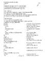
- FIG. 7provides a MATLAB code of one embodiment of the present invention.
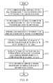
- FIG. 8is a flow chart illustrating a method of one embodiment of the present invention for calibrating a signal processing board.
- the present disclosureis directed towards a method and apparatus for equalizing an RF signal when the transmitted RF signal is converted between a stream of digitized RF samples and an analog RF signal.
- the RF signalis equalized to smooth a frequency response of the RF signal.
- RF signals on a given frequency within a bandare made similar in power to RF signals on other frequencies within the band, in order to achieve (ideally) a flat response across the frequency band.
- the RF signalis digitally equalized with a finite impulse response (FIR) filter.
- FIRfinite impulse response
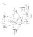
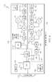
- FIG. 1is a block diagram of one embodiment of a distributed antenna system (DAS) 100 .
- DAS 100includes a host unit 102 and a plurality of remote units 106 .
- host units 102 and remote units 106are communicatively coupled via a communication link 130 to form a bidirectional communication network comprising a plurality of point-to-point communication links 130 .
- one or more of communication links 130are fiber optic cable as indicated in FIG. 1 .
- host units 102 and remote units 106may be interconnected via coaxial cable, or a combination of both coaxial cable and fiber optic cable.
- one or more of communication links 130are wireless millimeter wave links (e.g. E Band/70 GHz radio).
- a millimeter signal transceiveris coupled to host unit 102 and each remote unit 106 on each end of communication link 130 .
- one or more of communication links 130a microwave radio links where microwave radio transceivers are coupled to host unit 102 and remote units 106 .
- Remote units 106each house electronic devices and systems used for wirelessly transmitting and receiving modulated radio frequency (RF) communications via antenna 107 with one or more mobile subscriber units 108 .
- Host unit 102is coupled to at least one base transceiver station (BTS) 110 often referred to as a base station.
- BTS 110communicates voice and other data signals between the respective host unit 102 and a larger communication network via a gateway 124 coupled to a telephone system network 122 (for example, the public switched telephone network and/or wireless service provider networks) and an internet protocol (IP) network 120 , such as the Internet.
- IPinternet protocol
- DAS 100comprises part of a cellular telephone network and subscriber units 108 are cellular telephones.
- Downlink RF signalsare received from the BTS 110 at the host unit 102 , which the host unit 102 uses to generate one or more downlink transport signals for transmitting to one or more of the remote units 106 .
- Each such remote unit 106receives at least one downlink transport and reconstructs the downlink RF signals from the downlink transport signal and causes the reconstructed downlink RF signals to be radiated from a remote antenna 107 coupled to or included in that remote unit 106 .
- a similar processis performed in the uplink direction.
- Uplink RF signals received at one or more remote units 106 from subscriber 108are used to generate respective uplink transport signals that are transmitted from the respective remote units 106 to the host unit 102 .
- the host unit 102receives and combines the uplink transport signals transmitted from the multiple remote units 106 .
- the host unit 102communicates the combined uplink RF signals to the BTS 110 over a broadband signal.
- DAS 100comprises a digital DAS transport meaning that the downlink and uplink transport signals transmitted between host unit 102 and remote units 106 over communication links 130 are generated by digitizing the downlink and uplink RF signals, respectively.
- the downlink and uplink transport signalsare not analog RF signals but instead are digital data signals representing digital RF samples of a modulated RF signal.
- host unit 102will generate baseband digital samples of the modulated 900 MHz RF signal from BTS 110 , which are then distributed by host unit 102 to the remote units 106 .
- an all-digital BTSmay generate baseband digital samples directly.
- the digital samples of the modulated RF signalare converted from digital into an analog RF signal to be wirelessly radiated from the antennas 107 .
- the uplink analog RF signals received at remote unit 106are digitally sampled to generate digital RF data samples for the uplink transport signals.
- BTS 110 , host unit 102 and remote units 106each accommodate processing communication signals for multiple bands and multiple modulate schemes simultaneously.
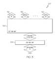
- FIG. 2is a block diagram of one embodiment of a remote unit 106 .
- Remote unit 106includes a serial radio frequency (SeRF) module 220 , a digital to analog radio frequency transceiver (DART) module 208 , a remote DART interface board (RDI) 224 , a linear power amplifier 210 , antenna 212 , a duplexer 211 , a low noise amplifier 214 .
- SeRF modules and DART modules described hereinare realized using FPGAs, ASICs, digital signal processing (DSP) boards, or similar devices.
- DART module 208provides bi-directional conversion between analog RF signals and digital sampled RF for the downlink and uplink transport signals transmitted between host unit 102 and remote units 106 .
- antenna 212receives a wireless RF signal from subscriber 208 and passes the RF signal to DART module 208 via low noise amplifier 214 .
- DART module 208receives the incoming analog RF signal and samples the analog RF signal to generate a digital data signal for use by SeRF module 220 .
- DART module 208receives digital sampled RF data from SeRF module 220 , up converts the sampled RF data to a broadcast frequency, and converts the digital RF samples to analog RF for wireless transmission.
- DART module 208After a signal is converted to an analog RF signal by DART module 208 , the analog RF signal is sent to power amplifier 210 for broadcast via antenna 212 .
- Power amplifier 210amplifies the RF signal received from DART module 208 for output through duplexer 211 to antenna 212 .
- Duplexer 211provides duplexing of the signal which is necessary to connect transmit and receive signals to a common antenna 212 .
- low noise amplifier 214is integrated into duplexer 211 .
- DART modulesmay function to optionally convert the digital RF samples into intermediate frequency (IF) samples instead of, or in addition to, baseband digital samples.
- IFintermediate frequency
- DART modules in a remote unitare specific for a particular frequency band.
- a single DART moduleoperates over a defined FDD band regardless of the modulation technology being used.
- frequency band adjustments in a remote unitcan be made by replacing a DART module covering one frequency band with a DART module covering a different frequency band.
- DART module 208is designed to transmit 850 MHz cellular transmissions.
- DART module 208transmits 1900 MHz PCS signals.
- Some of the other options for a DART module 208include Nextel 800 band, Nextel 900 band, PCS full band, PCS half band, BRS, WiMax, Long Term Evolution (LTE), and the European GSM 900, GSM 1800, and UMTS 2100.
- remote unit 106is configurable to any of the above frequency bands and technologies as well as any new technologies or frequency bands that are developed.
- SeRF module 220provides bi-directional conversion between a digital data stream and a high speed optical serial data stream.
- SeRF module 220receives incoming digital data streams from DART module 208 and sends a serial optical data stream over communication link 130 to host unit 102 .
- SeRF module 202receives an optical serial data stream from host unit 102 and provides a digital data stream to DART module 208 .
- SeRF module 220is coupled to RDI 224 .
- RDI 224has a plurality of connectors each of which is configured to receive a pluggable DART module 208 and couple DART module 208 to SeRF module 220 .
- RDI 224is a common interface that is configured to allow communication between SeRF module 220 and different varieties of DART modules 208 .
- RDI 204is a passive host backplane to which SeRF module 220 also connects.
- RDI 224is integrated with SeRF module 220 .
- FIG. 2illustrates a single DART module coupled to a SeRF module
- a single remote unit housingmay operate over multiple bands by possessing multiple DART modules.
- RDI 224provides separate connection interfaces allowing each DART module to communicate RF data samples with SeRF module 220 .
- SeRF module 220allows multiple DART modules to operate in parallel to communicate high speed optical serial data streams over a communication link with the host unit.
- a SeRF moduleactively multiplexes the signals from multiple DART modules (each DART module processing a different RF band) such that they are sent simultaneously over a single transport communication link.
- a SeRF modulepresents a clock signal to each DART module to which it is coupled to ensure synchronization.
- FIG. 2illustrates a single SeRF module connected to a single RDI
- a SeRF modulemay connect to multiple RDIs, each of which can connect to multiple DARTS.
- a SeRF modulecan connect to up to 3 RDIs, each of which can connect to up to 2 DARTs.
- SeRF module 220provides bi-directional conversion between a serial stream of RF, IF or baseband data samples (a SeRF stream) and a high speed optical serial data stream. In the uplink direction, SeRF module 220 receives an incoming SeRF stream from DART modules 208 and sends a serial optical data stream over communication links 130 to host unit 102 .
- SeRF module 220receives an optical serial data stream from host unit 102 and provides a SeRF stream to DART modules 208 .
- the present discussionapplies to such multiple band remote units, even though the present examples focus on the operation of a single DART module for simplicity.
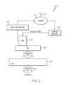
- FIG. 3is a block diagram illustrating one embodiment of a host unit (shown generally at 102 ).
- Host unit 102is communicatively coupled to multiple remote units 106 via communication links 130 , as described with respect to FIG. 1 , to form a digital DAS.
- Host unit 102includes a host unit digital to analog radio frequency transceiver (DART) module 308 and a host unit serial radio frequency (SeRF) module 320 .
- SeRF module 320provides bi-directional conversion between a digital RF data samples and the multiple high speed optical serial data streams to and from the remote units 106 .
- DARTdigital to analog radio frequency transceiver
- SeRFserial radio frequency
- SeRF module 320receives incoming serial optical data streams from a plurality of remote units and converts each into a stream of digitized baseband RF data samples, which are summed into a broadband stream of RF data samples.
- DART module 308provides a bi-directional interface between SeRF module 320 and one or more base stations, such as BTS 110 . As with remote units 106 , when host unit 320 operates over multiple bands with multiple base stations, a separate DART module 308 is provided for each frequency band.
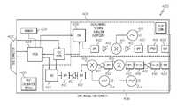
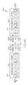
- FIG. 4is a block diagram of one embodiment of a DART module 400 for use in either host unit 102 (DART module 308 ) or remote units 106 (DART module 208 ).
- DART module 400has two main signal paths; a transmission path 404 and a reception path 406 .
- DART module 400forms parallel digital RF data from the incoming data stream, if needed, at FPGA 403 .
- FPGA 403is a logic device that is programmed to convert serial digital data into RF sampled data and programmed to convert RF sampled data into serial digital data.
- DART module 400then converts the digital RF data to an analog signal with digital to analog converter (DAC) 408 .
- DACdigital to analog converter
- Transmission path 404continues as DART module 400 filters, amplifies and up-converts the analog signal for RF transmission with an assortment of filters 410 , amplifiers 412 , an oscillator 414 , and an attenuator 416 .
- the transmission pathexits DART module 400 at a subminiature version A RF coaxial connector (SMA) connector 420 .
- SMAsubminiature version A RF coaxial connector
- the signalstravel in the opposite direction down reception path 406 , where they are converted from analog to digital and sent to a SeRF module.
- First signalsare received at SMA connector 420 .
- DART module 400then amplifies, down-converts, filters the incoming RF signal with a plurality of filters 410 , amplifiers 412 , oscillators 414 , and attenuators 416 .
- DART module 400then digitizes the signal with analog to digital converter 422 .
- FPGA 403then provides the data stream as parallel digital RF sampled data to a SeRF module. More detail regarding DAS 100 , host unit 102 , remote units 106 , or DART modules 400 is provided in co-pending U.S. application Ser. No. 11/627,251 which is hereby incorporated herein by reference.
- FPGA 403also digitally equalizes the signals propagating through DART module 400 by applying a filter to transmission and receive signals.
- a filterIn one embodiment, a finite impulse response (FIR) filter is used, and the FIR filter response is set to closely resemble an inverse frequency response of DART module 400 . The FIR filter therefore compensates for signal distortion caused by the DART module 400 .
- FPGA 403applies a filter to both the transmission and the reception signals within DART module 400 . Transmission signals are pre-compensated for by applying a filter to compensate for distortion caused by DAC 408 , band pass filters (BPF) 410 , amplifiers 412 and up-converter 411 .
- BPFband pass filters
- Reception signalsare post-compensated for by applying a filter to compensate for distortion cause by BPFs 410 , amplifiers 412 , and down-converters 413 .
- the filtersattempt to set transmission and reception signals to unity gain across the frequency band covered by DART module 400 .
- the filterequalizes across a 35 MHz band of signals.
- DAS 100comprises multiple pluggable and removable DART modules 400 .
- Each DART module 400is individually equalized to compensate for distortion caused by that particular DART module 400 .
- Thisenables any DART module 400 to be placed in a signal path with any other DART module 400 while providing adequate equalization to the signal path. Since a given signal path through DAS 100 travels through two DART modules 400 (one in the remote unit 106 and one in the host unit 102 ), and since the particular DART modules 400 that operate together on the given signal path are unknown prior to installation of DAS 100 , it is difficult to compensate for the specific distortion in the specific signal path prior to installation. Thus, individually equalizing the DART modules 400 enables the DART modules to be equalized prior to installation.
- DART modules 400can be plugged in any location, or replaced by any other DART module 400 while adequate equalization to the signal path.
- individually equalizing DART modules 400enables multicasting/simulcasting within DAS 100 . Accordingly, within a given DAS signal path, a portion of the equalizing is done at host unit DART module 208 and another portion is done at remote unit DART module 308 . This is true of both uplink and downlink signals.
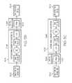
- FIG. 5Aillustrates one embodiment of a RF signal path 500 through DAS 100 .
- An analog RF signal 502is input into signal path 500 .
- the analog RF signalis filtered with a surface acoustic wave (SAW) filter (BPF 410 of FIG. 4 ), down-converted (down-converters 413 of FIG. 4 ), and filtered again before being converted to digital RF samples.
- SAWsurface acoustic wave
- each DART module 400The distortion in each DART module 400 is equalized by FPGA 403 in each DART module 400 .
- Each FPGA 403 in each DART module 400applies a filter (referred to herein as H( ⁇ )) to the signal.
- H( ⁇ )a filter
- G 1 ( ⁇ ) distortionis compensated for by the H 1 ( ⁇ ) filter
- G 2 ( ⁇ ) distortionis compensated for by the H 2 ( ⁇ ) filter.
- FIG. 5Billustrates one method for determining the filter coefficients for a receive path filter (H 1 ( ⁇ )).
- 5 Cillustrates one method for determining the filter coefficients for a transmission path filter (H 2 ( ⁇ )).
- test signalsare input into the DART module and output signals are measured to determine the distortion caused by the DART module. Based on the measured output signals filter coefficients are determined. The filter coefficients are then set such that the filter applies the inverse of the distortion introduced by the DART module.
- a frequency sweep test signal from a signal generator 502is applied to receive path 404 of a DART module 400 .
- the test signalscan be generated with any suitable signal generator.
- FPGA 403applies a flat filter response.
- the output signal at edge connector 402 of DART module 400 that results from the test signalis then measured with a spectrum analyzer 504 .
- H 1 ( ⁇ )an analog RF test signal is applied to the receive path 404 and a digitized signal output at the edge connector 402 is analyzed using a spectral estimation algorithm to determine the amplitude response of the system.
- the input test signalsare all input with equal amplitude, thus variations in the amplitude of output signals are the result of distortion in receive path 404 of DART module 400 .
- the filter coefficientsare then set such that the filter cancels out the distortion caused by receive path 404 in DART module 400 .
- future signals input into receive path 404will be distorted by receive path 404 and equalized by FPGA 403 such that the output signals will (ideally) have the same relative amplitude (amplitude relative to other output signals) as the amplitude of input signals relative to other input signals.
- the H 2 ( ⁇ ) filter coefficients for DART module 400are determined in a similar manner except test signals are input into the edge connector 402 of DART module 400 and the resulting output signals are measured with a spectrum analyzer 504 at an SMA connector 420 .
- a digitized signalis applied to the transmit path at the edge connector 402 and the resulting analog RF output signal measured at the SMA connector 420 with an RF spectrum analyzer or RF detector to determine the signal amplitude.
- the output signalsare measured with an RF detector.
- the digitized signalis generated within the FPGA 403 rather than applied from an external device.
- the input test signals for determining H 1 ( ⁇ ) and H 2 ( ⁇ )are referred to as frequency sweep signals.
- Table 1provides an arrangement of parameters for measured amplitude response of a component of a distributed antenna system such as a DART module.
- Ge ⁇ ( ⁇ )Gm ⁇ ( n ) + ( ⁇ - Fm ⁇ ( n ) ) ⁇ Gm ⁇ ( n + 1 ) - Gm ⁇ ( n ) Fm ⁇ ( n + 1 ) - Fm ⁇ ( n ) ⁇ ⁇ for ⁇ ⁇ 0 ⁇ Fm ⁇ ( n ) ⁇ ⁇ ⁇ Fm ⁇ ( n + 1 ) ⁇ 0.5 ( 1 )
- a frequency comb test signalconsisting of a series of sinusoids of equal amplitude spaced evenly across the digital spectrum will allow determination of an inverse FIR filter to equalize the amplitude response of the system.
- Table 2describes the relationship between a frequency comb signal x(n) and an approximation y(n) of a system response output.
- the frequency comb signal x(n)is applied to a model of the system described by the approximation of the overall system response Ge( ⁇ ), which is based on an interpolation of the K measurements of the amplitude made with the frequency sweep signal.
- the purpose of the frequency combis merely for calculation and consists of C tones which, in general, can be greater than the number K.
- frequency comb signal x(n)is generated and resides within a computer used to calculate estimates of an H( ⁇ ) which could be H 1 ( ⁇ ) or H 2 ( ⁇ ).
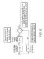
- FIG. 6illustrates a signal model (shown generally at 600 ) for determining an FIR filter H( ⁇ ) that estimates the inverse of a linear channel response. Determination of the FIR filter H( ⁇ ) is based on a least squares fit and will find the parameters of an FIR filter that will equalize a channel G( ⁇ ) that has linear distortion.
- d(n)represents the desired system response, which in one embodiment, is a delayed version of the input.
- ⁇ circumflex over (d) ⁇ (n)is the equalized system response resulting from the cascade of the channel distortion G( ⁇ ) and the approximated system inverse filter H( ⁇ ).
- the error term e(n)can be expressed in terms of the channel output y(n) and the desired channel output d(n) as
- An optimal solution to equationcan be found using the least squares method which minimizes the sum of the square of the error terms e(n).
- FIG. 7provides a MATLAB code generally at 700 that can be used to perform the least squares estimate of the inverse filter.
- Table 3summarizes the calculation used therein for deriving the inverse FIR filter.
- the filter coefficientsare stored in a memory 424 on DART module 400 . Once the coefficients are determined as described above, the coefficients are stored in memory 424 and accessed by FPGA 403 when FPGA 403 applies a filter to a signal. Since, each DART module 400 has two signal paths (transmission and receive) with differing distortions, each signal path has its own set of coefficients stored in memory 424 . Thus, when FPGA 403 is processing transmission path signals, FPGA 403 accesses the transmission path filter coefficients and applies a filter having those coefficients to the transmission path signal Likewise, when FPGA 403 is processing receive path signals, FPGA 403 accesses the receive path filter coefficients and applies a filter having those coefficients to the receive path signal.
- DART module 400is equalized in the factory after manufacture of DART module 400 .
- a signal generator in the factoryinputs signals into DART module 400 and a spectrum analyzer analyzes the output signal.
- a bufferis used to capture the output signal.
- a fast Fourier transform (FFT)is then used to convert the output signal to the frequency domain. Once in the frequency domain, the output signal power at each frequency is easily determined.
- the coefficients for the filterare stored in memory 424 .
- Memory 424is separate from FPGA 403 , such that the coefficients can be stored in memory 424 without having to integrate the coefficients into FPGA 403 . Accordingly, FPGA 403 can be programmed separately, or at a later time as desired with a more generic function. In this way, the filter response can be individualized for each DART module 400 without having to individualize the FPGA programming.
- DART module 400comprises a self-calibration module 426 .
- Self-calibration module 426performs the steps listed above to generate test signals and analyze output signals to determine the appropriate filter coefficients for DART module 400 .
- Self-calibration module 426could be programmed to calibrate DART module 400 at regular intervals, or could be manually initiated when, for example, DART module 400 is tuned to a different frequency band.
- FIG. 8is a flow chart illustrating a method of one embodiment of the present invention for calibrating a signal processing board such as a DART module.
- the methodbegins as 810 with setting a compensator within a first signal path of a signal processing board to have a flat response across a first pass band of the signal processing board.
- the first signal pathmay include components such as, but not limited to digital-to-analog converters (DACs), analog-to-digital converters (ADCs), SAW filters, and frequency up-converters and down-converters.
- DACsdigital-to-analog converters
- ADCsanalog-to-digital converters
- SAW filtersSAW filters
- frequency up-converters and down-convertersand frequency up-converters and down-converters.
- the plurality of test signalscomprises a plurality frequency sweep signals consisting of a series of sinusoids of equal amplitude spaced evenly across a digital spectrum of the first pass band.
- the methodproceeds to 830 with determining a gain value for each of the plurality of test signals based on an output of the signal processing board.
- the methodproceeds to 840 with estimating a system response function y(n) for the signal processing board based on the gain value for each of the plurality of test signals.
- amplitude gain values Gm(n)are measured through application of the frequency sweep signal on the physical system. There are K such measurements plus two end points, so n is an index variable from 0 to K+1. Therefore, this frequency sweep can actually take course steps across the channel band.
- Ge( ⁇ ), defined above at Equation (1)represents an estimation of the amplitude response of the system as a function of normalized frequency in units of samples. That is, Ge( ⁇ ) is an interpolation of Gm(n) and the corresponding frequencies Fm(n) where Gm(n) was measured.
- G(m), defined above in Table 2represents C samples of Ge( ⁇ ) taken at each of the C frequencies of the tones contained in the frequency comb test signal x(n). There are C samples, so m is an index that can range from 0 to C ⁇ 1.
- the function y(n)is thus the estimated system output that would be produced for an input frequency comb test signal x(n) and an approximation Ge( ⁇ ) of the system response.
- the methodproceeds to 850 with solving for coefficients of a vector h(n) based on a difference between a vector d(n) and a convolution h(n)*y(n), wherein d(n) represents an input to the system response function y(n) subject to a delay. It is, in other words, a delayed version of the frequency comb test signal x(n).
- the vector h(n)is determined such that the squared error between d(n) and h(n)*y(n) is minimized with respect to h(n).
- the methodproceeds to 850 with solving for coefficients of a vector h(n) based on a difference between a vector d(n) and a convolution h(n)*y(n), wherein d(n) represents an input to the system response function y(n) subject to a delay.
- the difference between the vector d(n) and the convolution h(n)*y(n)is zero.
- the methodproceed to 860 with setting coefficients of a finite impulse response (FIR) filter within the compensator based on the coefficients of the vector h(n).
- FIRfinite impulse response
Landscapes
- Engineering & Computer Science (AREA)
- Computer Networks & Wireless Communication (AREA)
- Signal Processing (AREA)
- Power Engineering (AREA)
- Radar Systems Or Details Thereof (AREA)
- Digital Transmission Methods That Use Modulated Carrier Waves (AREA)
- Cable Transmission Systems, Equalization Of Radio And Reduction Of Echo (AREA)
Abstract
Description
| TABLE 1 | ||
| Parameter | Symbol | Value |
| Start of pass band | Fa | Given normalized start frequency of pass band. |
| (units of samples) | ||
| End of pass band | Fb | Given normalized end frequency of pass band. |
| (units of samples) | ||
| Pass band width | bw | bw = Fb − Fa |
| Number of measured | K | Given, K = 11 for example |
| data points | ||
| Frequency points of measurement | Fm | |
| Measured gain values | Gm | |
| TABLE 2 |
| Input and output frequency comb test signals. |
| Parameter | Symbol | Value |
| Number of tones | C | Given, C = 128 in example |
| System gain response | G | |
| Length of test signals | M | Given, M = 16C in example |
| Input comb signal | x | |
| Output comb signal | y | |
where h(n)*y(n) is the convolution operation. Taking M consecutive samples of y(n) and d(n), and setting e(n)=0, equation (2) can be expressed in matrix form as a set of M+N−1 over determined linear equations:
or more concisely as
{right arrow over (Y)}{right arrow over (h)}={right arrow over (d)} (4)
where {right arrow over (Y)} is the convolution matrix of the channel output samples, {right arrow over (h)} is the vector of FIR filter parameters (the unit pulse response of the FIR filter), and {right arrow over (d)} is a vector of the desired channel output samples (a delayed version of the input). An optimal solution to equation can be found using the least squares method which minimizes the sum of the square of the error terms e(n). The least squares solution is found by solving the set of linear equations
({right arrow over (Y)}H{right arrow over (Y)}){right arrow over (h)}={right arrow over (Y)}H{right arrow over (d)} (5)
or
{right arrow over (h)}=({right arrow over (Y)}H{right arrow over (Y)})−1{right arrow over (Y)}H{right arrow over (d)} (6)
| TABLE 3 | ||
| Parameter | Symbol | Value |
| Number of FIR | N | Given, N = 11 for example |
| Taps | ||
| Channel delay | n0 | Given, n0 = 5 for example |
| Desired channel | d | d(n) = x(n − n0] for 0 ≦ n ≦ M + N − 2 |
| output | ||
| Convolution matrix | Ycm | Ycm(r, c) = {right arrow over (Y)}r, cfor 1 ≦ r ≦ N + M − 1 |
| of the system | and 1 ≦ c ≦ N | |
| impulse response | (see equations (3)-(6) above) | |
| Inverse FIR | h | h(n) = {right arrow over (h)}n+1for 0 ≦ n ≦ N − 1 |
| filter taps | (see equations (3)-(6) above) | |
| Squared error | E | E = ({right arrow over (Y)} {right arrow over (h)} − d)H· ({right arrow over (Y)} {right arrow over (h)} − d) |
Claims (13)
Priority Applications (1)
| Application Number | Priority Date | Filing Date | Title |
|---|---|---|---|
| US13/411,926US8437383B2 (en) | 2009-01-27 | 2012-03-05 | Method and apparatus for digitally equalizing a signal in a distributed antenna system |
Applications Claiming Priority (3)
| Application Number | Priority Date | Filing Date | Title |
|---|---|---|---|
| US14756009P | 2009-01-27 | 2009-01-27 | |
| US12/643,410US8135102B2 (en) | 2009-01-27 | 2009-12-21 | Method and apparatus for digitally equalizing a signal in a distributed antenna system |
| US13/411,926US8437383B2 (en) | 2009-01-27 | 2012-03-05 | Method and apparatus for digitally equalizing a signal in a distributed antenna system |
Related Parent Applications (1)
| Application Number | Title | Priority Date | Filing Date |
|---|---|---|---|
| US12/643,410ContinuationUS8135102B2 (en) | 2009-01-27 | 2009-12-21 | Method and apparatus for digitally equalizing a signal in a distributed antenna system |
Publications (2)
| Publication Number | Publication Date |
|---|---|
| US20120163431A1 US20120163431A1 (en) | 2012-06-28 |
| US8437383B2true US8437383B2 (en) | 2013-05-07 |
Family
ID=42354140
Family Applications (2)
| Application Number | Title | Priority Date | Filing Date |
|---|---|---|---|
| US12/643,410Active2030-11-02US8135102B2 (en) | 2009-01-27 | 2009-12-21 | Method and apparatus for digitally equalizing a signal in a distributed antenna system |
| US13/411,926Expired - Fee RelatedUS8437383B2 (en) | 2009-01-27 | 2012-03-05 | Method and apparatus for digitally equalizing a signal in a distributed antenna system |
Family Applications Before (1)
| Application Number | Title | Priority Date | Filing Date |
|---|---|---|---|
| US12/643,410Active2030-11-02US8135102B2 (en) | 2009-01-27 | 2009-12-21 | Method and apparatus for digitally equalizing a signal in a distributed antenna system |
Country Status (7)
| Country | Link |
|---|---|
| US (2) | US8135102B2 (en) |
| EP (1) | EP2392075A4 (en) |
| JP (1) | JP2012516635A (en) |
| KR (1) | KR101355501B1 (en) |
| CN (1) | CN102301606B (en) |
| AU (1) | AU2009338702B2 (en) |
| WO (1) | WO2010087919A2 (en) |
Cited By (163)
| Publication number | Priority date | Publication date | Assignee | Title |
|---|---|---|---|---|
| US9525210B2 (en) | 2014-10-21 | 2016-12-20 | At&T Intellectual Property I, L.P. | Guided-wave transmission device with non-fundamental mode propagation and methods for use therewith |
| US9531427B2 (en) | 2014-11-20 | 2016-12-27 | At&T Intellectual Property I, L.P. | Transmission device with mode division multiplexing and methods for use therewith |
| US9564947B2 (en) | 2014-10-21 | 2017-02-07 | At&T Intellectual Property I, L.P. | Guided-wave transmission device with diversity and methods for use therewith |
| US9577306B2 (en) | 2014-10-21 | 2017-02-21 | At&T Intellectual Property I, L.P. | Guided-wave transmission device and methods for use therewith |
| US9596001B2 (en) | 2014-10-21 | 2017-03-14 | At&T Intellectual Property I, L.P. | Apparatus for providing communication services and methods thereof |
| US9608692B2 (en) | 2015-06-11 | 2017-03-28 | At&T Intellectual Property I, L.P. | Repeater and methods for use therewith |
| US9608740B2 (en) | 2015-07-15 | 2017-03-28 | At&T Intellectual Property I, L.P. | Method and apparatus for launching a wave mode that mitigates interference |
| US9615269B2 (en) | 2014-10-02 | 2017-04-04 | At&T Intellectual Property I, L.P. | Method and apparatus that provides fault tolerance in a communication network |
| US9628116B2 (en) | 2015-07-14 | 2017-04-18 | At&T Intellectual Property I, L.P. | Apparatus and methods for transmitting wireless signals |
| US9628854B2 (en) | 2014-09-29 | 2017-04-18 | At&T Intellectual Property I, L.P. | Method and apparatus for distributing content in a communication network |
| US9640850B2 (en) | 2015-06-25 | 2017-05-02 | At&T Intellectual Property I, L.P. | Methods and apparatus for inducing a non-fundamental wave mode on a transmission medium |
| US9653770B2 (en) | 2014-10-21 | 2017-05-16 | At&T Intellectual Property I, L.P. | Guided wave coupler, coupling module and methods for use therewith |
| US9654173B2 (en) | 2014-11-20 | 2017-05-16 | At&T Intellectual Property I, L.P. | Apparatus for powering a communication device and methods thereof |
| US9661505B2 (en) | 2013-11-06 | 2017-05-23 | At&T Intellectual Property I, L.P. | Surface-wave communications and methods thereof |
| US9667317B2 (en) | 2015-06-15 | 2017-05-30 | At&T Intellectual Property I, L.P. | Method and apparatus for providing security using network traffic adjustments |
| US9680670B2 (en) | 2014-11-20 | 2017-06-13 | At&T Intellectual Property I, L.P. | Transmission device with channel equalization and control and methods for use therewith |
| US9685992B2 (en) | 2014-10-03 | 2017-06-20 | At&T Intellectual Property I, L.P. | Circuit panel network and methods thereof |
| US9692101B2 (en) | 2014-08-26 | 2017-06-27 | At&T Intellectual Property I, L.P. | Guided wave couplers for coupling electromagnetic waves between a waveguide surface and a surface of a wire |
| US9699785B2 (en) | 2012-12-05 | 2017-07-04 | At&T Intellectual Property I, L.P. | Backhaul link for distributed antenna system |
| US9705571B2 (en) | 2015-09-16 | 2017-07-11 | At&T Intellectual Property I, L.P. | Method and apparatus for use with a radio distributed antenna system |
| US9705561B2 (en) | 2015-04-24 | 2017-07-11 | At&T Intellectual Property I, L.P. | Directional coupling device and methods for use therewith |
| US9705610B2 (en) | 2014-10-21 | 2017-07-11 | At&T Intellectual Property I, L.P. | Transmission device with impairment compensation and methods for use therewith |
| US9722318B2 (en) | 2015-07-14 | 2017-08-01 | At&T Intellectual Property I, L.P. | Method and apparatus for coupling an antenna to a device |
| US9729197B2 (en) | 2015-10-01 | 2017-08-08 | At&T Intellectual Property I, L.P. | Method and apparatus for communicating network management traffic over a network |
| US9735833B2 (en) | 2015-07-31 | 2017-08-15 | At&T Intellectual Property I, L.P. | Method and apparatus for communications management in a neighborhood network |
| US9742462B2 (en) | 2014-12-04 | 2017-08-22 | At&T Intellectual Property I, L.P. | Transmission medium and communication interfaces and methods for use therewith |
| US9748626B2 (en) | 2015-05-14 | 2017-08-29 | At&T Intellectual Property I, L.P. | Plurality of cables having different cross-sectional shapes which are bundled together to form a transmission medium |
| US9749053B2 (en) | 2015-07-23 | 2017-08-29 | At&T Intellectual Property I, L.P. | Node device, repeater and methods for use therewith |
| US9749013B2 (en) | 2015-03-17 | 2017-08-29 | At&T Intellectual Property I, L.P. | Method and apparatus for reducing attenuation of electromagnetic waves guided by a transmission medium |
| US9762289B2 (en) | 2014-10-14 | 2017-09-12 | At&T Intellectual Property I, L.P. | Method and apparatus for transmitting or receiving signals in a transportation system |
| US9768833B2 (en) | 2014-09-15 | 2017-09-19 | At&T Intellectual Property I, L.P. | Method and apparatus for sensing a condition in a transmission medium of electromagnetic waves |
| US9769020B2 (en) | 2014-10-21 | 2017-09-19 | At&T Intellectual Property I, L.P. | Method and apparatus for responding to events affecting communications in a communication network |
| US9769128B2 (en) | 2015-09-28 | 2017-09-19 | At&T Intellectual Property I, L.P. | Method and apparatus for encryption of communications over a network |
| US9780834B2 (en) | 2014-10-21 | 2017-10-03 | At&T Intellectual Property I, L.P. | Method and apparatus for transmitting electromagnetic waves |
| US9787412B2 (en) | 2015-06-25 | 2017-10-10 | At&T Intellectual Property I, L.P. | Methods and apparatus for inducing a fundamental wave mode on a transmission medium |
| US9793955B2 (en) | 2015-04-24 | 2017-10-17 | At&T Intellectual Property I, Lp | Passive electrical coupling device and methods for use therewith |
| US9793954B2 (en) | 2015-04-28 | 2017-10-17 | At&T Intellectual Property I, L.P. | Magnetic coupling device and methods for use therewith |
| US9793951B2 (en) | 2015-07-15 | 2017-10-17 | At&T Intellectual Property I, L.P. | Method and apparatus for launching a wave mode that mitigates interference |
| US9794003B2 (en) | 2013-12-10 | 2017-10-17 | At&T Intellectual Property I, L.P. | Quasi-optical coupler |
| US9800327B2 (en) | 2014-11-20 | 2017-10-24 | At&T Intellectual Property I, L.P. | Apparatus for controlling operations of a communication device and methods thereof |
| US9820146B2 (en) | 2015-06-12 | 2017-11-14 | At&T Intellectual Property I, L.P. | Method and apparatus for authentication and identity management of communicating devices |
| US9838896B1 (en) | 2016-12-09 | 2017-12-05 | At&T Intellectual Property I, L.P. | Method and apparatus for assessing network coverage |
| US9838078B2 (en) | 2015-07-31 | 2017-12-05 | At&T Intellectual Property I, L.P. | Method and apparatus for exchanging communication signals |
| US9836957B2 (en) | 2015-07-14 | 2017-12-05 | At&T Intellectual Property I, L.P. | Method and apparatus for communicating with premises equipment |
| US9847850B2 (en) | 2014-10-14 | 2017-12-19 | At&T Intellectual Property I, L.P. | Method and apparatus for adjusting a mode of communication in a communication network |
| US9847566B2 (en) | 2015-07-14 | 2017-12-19 | At&T Intellectual Property I, L.P. | Method and apparatus for adjusting a field of a signal to mitigate interference |
| US9853342B2 (en) | 2015-07-14 | 2017-12-26 | At&T Intellectual Property I, L.P. | Dielectric transmission medium connector and methods for use therewith |
| US9860075B1 (en) | 2016-08-26 | 2018-01-02 | At&T Intellectual Property I, L.P. | Method and communication node for broadband distribution |
| US9866276B2 (en) | 2014-10-10 | 2018-01-09 | At&T Intellectual Property I, L.P. | Method and apparatus for arranging communication sessions in a communication system |
| US9865911B2 (en) | 2015-06-25 | 2018-01-09 | At&T Intellectual Property I, L.P. | Waveguide system for slot radiating first electromagnetic waves that are combined into a non-fundamental wave mode second electromagnetic wave on a transmission medium |
| US9866309B2 (en) | 2015-06-03 | 2018-01-09 | At&T Intellectual Property I, Lp | Host node device and methods for use therewith |
| US9871282B2 (en) | 2015-05-14 | 2018-01-16 | At&T Intellectual Property I, L.P. | At least one transmission medium having a dielectric surface that is covered at least in part by a second dielectric |
| US9871283B2 (en) | 2015-07-23 | 2018-01-16 | At&T Intellectual Property I, Lp | Transmission medium having a dielectric core comprised of plural members connected by a ball and socket configuration |
| US9876264B2 (en) | 2015-10-02 | 2018-01-23 | At&T Intellectual Property I, Lp | Communication system, guided wave switch and methods for use therewith |
| US9876571B2 (en) | 2015-02-20 | 2018-01-23 | At&T Intellectual Property I, Lp | Guided-wave transmission device with non-fundamental mode propagation and methods for use therewith |
| US9876605B1 (en) | 2016-10-21 | 2018-01-23 | At&T Intellectual Property I, L.P. | Launcher and coupling system to support desired guided wave mode |
| US9882257B2 (en) | 2015-07-14 | 2018-01-30 | At&T Intellectual Property I, L.P. | Method and apparatus for launching a wave mode that mitigates interference |
| US9882277B2 (en) | 2015-10-02 | 2018-01-30 | At&T Intellectual Property I, Lp | Communication device and antenna assembly with actuated gimbal mount |
| US9887447B2 (en) | 2015-05-14 | 2018-02-06 | At&T Intellectual Property I, L.P. | Transmission medium having multiple cores and methods for use therewith |
| US9893795B1 (en) | 2016-12-07 | 2018-02-13 | At&T Intellectual Property I, Lp | Method and repeater for broadband distribution |
| US9906269B2 (en) | 2014-09-17 | 2018-02-27 | At&T Intellectual Property I, L.P. | Monitoring and mitigating conditions in a communication network |
| US9904535B2 (en) | 2015-09-14 | 2018-02-27 | At&T Intellectual Property I, L.P. | Method and apparatus for distributing software |
| US9912381B2 (en) | 2015-06-03 | 2018-03-06 | At&T Intellectual Property I, Lp | Network termination and methods for use therewith |
| US9913139B2 (en) | 2015-06-09 | 2018-03-06 | At&T Intellectual Property I, L.P. | Signal fingerprinting for authentication of communicating devices |
| US9912027B2 (en) | 2015-07-23 | 2018-03-06 | At&T Intellectual Property I, L.P. | Method and apparatus for exchanging communication signals |
| US9911020B1 (en) | 2016-12-08 | 2018-03-06 | At&T Intellectual Property I, L.P. | Method and apparatus for tracking via a radio frequency identification device |
| US9912419B1 (en) | 2016-08-24 | 2018-03-06 | At&T Intellectual Property I, L.P. | Method and apparatus for managing a fault in a distributed antenna system |
| US9917341B2 (en) | 2015-05-27 | 2018-03-13 | At&T Intellectual Property I, L.P. | Apparatus and method for launching electromagnetic waves and for modifying radial dimensions of the propagating electromagnetic waves |
| US9930668B2 (en) | 2013-05-31 | 2018-03-27 | At&T Intellectual Property I, L.P. | Remote distributed antenna system |
| US9927517B1 (en) | 2016-12-06 | 2018-03-27 | At&T Intellectual Property I, L.P. | Apparatus and methods for sensing rainfall |
| US9948354B2 (en) | 2015-04-28 | 2018-04-17 | At&T Intellectual Property I, L.P. | Magnetic coupling device with reflective plate and methods for use therewith |
| US9948333B2 (en) | 2015-07-23 | 2018-04-17 | At&T Intellectual Property I, L.P. | Method and apparatus for wireless communications to mitigate interference |
| US9954287B2 (en) | 2014-11-20 | 2018-04-24 | At&T Intellectual Property I, L.P. | Apparatus for converting wireless signals and electromagnetic waves and methods thereof |
| US9967173B2 (en) | 2015-07-31 | 2018-05-08 | At&T Intellectual Property I, L.P. | Method and apparatus for authentication and identity management of communicating devices |
| US9973940B1 (en) | 2017-02-27 | 2018-05-15 | At&T Intellectual Property I, L.P. | Apparatus and methods for dynamic impedance matching of a guided wave launcher |
| US9991580B2 (en) | 2016-10-21 | 2018-06-05 | At&T Intellectual Property I, L.P. | Launcher and coupling system for guided wave mode cancellation |
| US9997819B2 (en) | 2015-06-09 | 2018-06-12 | At&T Intellectual Property I, L.P. | Transmission medium and method for facilitating propagation of electromagnetic waves via a core |
| US9999038B2 (en) | 2013-05-31 | 2018-06-12 | At&T Intellectual Property I, L.P. | Remote distributed antenna system |
| US9998870B1 (en) | 2016-12-08 | 2018-06-12 | At&T Intellectual Property I, L.P. | Method and apparatus for proximity sensing |
| US10009901B2 (en) | 2015-09-16 | 2018-06-26 | At&T Intellectual Property I, L.P. | Method, apparatus, and computer-readable storage medium for managing utilization of wireless resources between base stations |
| US10009065B2 (en) | 2012-12-05 | 2018-06-26 | At&T Intellectual Property I, L.P. | Backhaul link for distributed antenna system |
| US10009067B2 (en) | 2014-12-04 | 2018-06-26 | At&T Intellectual Property I, L.P. | Method and apparatus for configuring a communication interface |
| US10009063B2 (en) | 2015-09-16 | 2018-06-26 | At&T Intellectual Property I, L.P. | Method and apparatus for use with a radio distributed antenna system having an out-of-band reference signal |
| US10020587B2 (en) | 2015-07-31 | 2018-07-10 | At&T Intellectual Property I, L.P. | Radial antenna and methods for use therewith |
| US10020844B2 (en) | 2016-12-06 | 2018-07-10 | T&T Intellectual Property I, L.P. | Method and apparatus for broadcast communication via guided waves |
| US10027397B2 (en) | 2016-12-07 | 2018-07-17 | At&T Intellectual Property I, L.P. | Distributed antenna system and methods for use therewith |
| US10033107B2 (en) | 2015-07-14 | 2018-07-24 | At&T Intellectual Property I, L.P. | Method and apparatus for coupling an antenna to a device |
| US10033108B2 (en) | 2015-07-14 | 2018-07-24 | At&T Intellectual Property I, L.P. | Apparatus and methods for generating an electromagnetic wave having a wave mode that mitigates interference |
| US10044409B2 (en) | 2015-07-14 | 2018-08-07 | At&T Intellectual Property I, L.P. | Transmission medium and methods for use therewith |
| US10051483B2 (en) | 2015-10-16 | 2018-08-14 | At&T Intellectual Property I, L.P. | Method and apparatus for directing wireless signals |
| US10051629B2 (en) | 2015-09-16 | 2018-08-14 | At&T Intellectual Property I, L.P. | Method and apparatus for use with a radio distributed antenna system having an in-band reference signal |
| US10069535B2 (en) | 2016-12-08 | 2018-09-04 | At&T Intellectual Property I, L.P. | Apparatus and methods for launching electromagnetic waves having a certain electric field structure |
| US10074890B2 (en) | 2015-10-02 | 2018-09-11 | At&T Intellectual Property I, L.P. | Communication device and antenna with integrated light assembly |
| US10079661B2 (en) | 2015-09-16 | 2018-09-18 | At&T Intellectual Property I, L.P. | Method and apparatus for use with a radio distributed antenna system having a clock reference |
| US10090606B2 (en) | 2015-07-15 | 2018-10-02 | At&T Intellectual Property I, L.P. | Antenna system with dielectric array and methods for use therewith |
| US10090594B2 (en) | 2016-11-23 | 2018-10-02 | At&T Intellectual Property I, L.P. | Antenna system having structural configurations for assembly |
| US10103801B2 (en) | 2015-06-03 | 2018-10-16 | At&T Intellectual Property I, L.P. | Host node device and methods for use therewith |
| US10103422B2 (en) | 2016-12-08 | 2018-10-16 | At&T Intellectual Property I, L.P. | Method and apparatus for mounting network devices |
| US10116376B2 (en) | 2014-08-12 | 2018-10-30 | Kathrein-Werke Kg | Method and system for relaying telecommunications signals |
| US10135145B2 (en) | 2016-12-06 | 2018-11-20 | At&T Intellectual Property I, L.P. | Apparatus and methods for generating an electromagnetic wave along a transmission medium |
| US10135146B2 (en) | 2016-10-18 | 2018-11-20 | At&T Intellectual Property I, L.P. | Apparatus and methods for launching guided waves via circuits |
| US10136434B2 (en) | 2015-09-16 | 2018-11-20 | At&T Intellectual Property I, L.P. | Method and apparatus for use with a radio distributed antenna system having an ultra-wideband control channel |
| US10135147B2 (en) | 2016-10-18 | 2018-11-20 | At&T Intellectual Property I, L.P. | Apparatus and methods for launching guided waves via an antenna |
| US10142086B2 (en) | 2015-06-11 | 2018-11-27 | At&T Intellectual Property I, L.P. | Repeater and methods for use therewith |
| US10139820B2 (en) | 2016-12-07 | 2018-11-27 | At&T Intellectual Property I, L.P. | Method and apparatus for deploying equipment of a communication system |
| US10148466B2 (en) | 2014-12-11 | 2018-12-04 | Corning Optical Communications Wireless Ltd. | Broad band and narrow band frequency response equalization |
| US10148016B2 (en) | 2015-07-14 | 2018-12-04 | At&T Intellectual Property I, L.P. | Apparatus and methods for communicating utilizing an antenna array |
| US10144036B2 (en) | 2015-01-30 | 2018-12-04 | At&T Intellectual Property I, L.P. | Method and apparatus for mitigating interference affecting a propagation of electromagnetic waves guided by a transmission medium |
| US10154493B2 (en) | 2015-06-03 | 2018-12-11 | At&T Intellectual Property I, L.P. | Network termination and methods for use therewith |
| US10168695B2 (en) | 2016-12-07 | 2019-01-01 | At&T Intellectual Property I, L.P. | Method and apparatus for controlling an unmanned aircraft |
| US10170840B2 (en) | 2015-07-14 | 2019-01-01 | At&T Intellectual Property I, L.P. | Apparatus and methods for sending or receiving electromagnetic signals |
| US10178445B2 (en) | 2016-11-23 | 2019-01-08 | At&T Intellectual Property I, L.P. | Methods, devices, and systems for load balancing between a plurality of waveguides |
| US10205655B2 (en) | 2015-07-14 | 2019-02-12 | At&T Intellectual Property I, L.P. | Apparatus and methods for communicating utilizing an antenna array and multiple communication paths |
| US10225025B2 (en) | 2016-11-03 | 2019-03-05 | At&T Intellectual Property I, L.P. | Method and apparatus for detecting a fault in a communication system |
| US10224634B2 (en) | 2016-11-03 | 2019-03-05 | At&T Intellectual Property I, L.P. | Methods and apparatus for adjusting an operational characteristic of an antenna |
| US10243270B2 (en) | 2016-12-07 | 2019-03-26 | At&T Intellectual Property I, L.P. | Beam adaptive multi-feed dielectric antenna system and methods for use therewith |
| US10243784B2 (en) | 2014-11-20 | 2019-03-26 | At&T Intellectual Property I, L.P. | System for generating topology information and methods thereof |
| US10264586B2 (en) | 2016-12-09 | 2019-04-16 | At&T Mobility Ii Llc | Cloud-based packet controller and methods for use therewith |
| US10291311B2 (en) | 2016-09-09 | 2019-05-14 | At&T Intellectual Property I, L.P. | Method and apparatus for mitigating a fault in a distributed antenna system |
| US10291334B2 (en) | 2016-11-03 | 2019-05-14 | At&T Intellectual Property I, L.P. | System for detecting a fault in a communication system |
| US10298293B2 (en) | 2017-03-13 | 2019-05-21 | At&T Intellectual Property I, L.P. | Apparatus of communication utilizing wireless network devices |
| US10305190B2 (en) | 2016-12-01 | 2019-05-28 | At&T Intellectual Property I, L.P. | Reflecting dielectric antenna system and methods for use therewith |
| US10312567B2 (en) | 2016-10-26 | 2019-06-04 | At&T Intellectual Property I, L.P. | Launcher with planar strip antenna and methods for use therewith |
| US10320586B2 (en) | 2015-07-14 | 2019-06-11 | At&T Intellectual Property I, L.P. | Apparatus and methods for generating non-interfering electromagnetic waves on an insulated transmission medium |
| US10326689B2 (en) | 2016-12-08 | 2019-06-18 | At&T Intellectual Property I, L.P. | Method and system for providing alternative communication paths |
| US10326494B2 (en) | 2016-12-06 | 2019-06-18 | At&T Intellectual Property I, L.P. | Apparatus for measurement de-embedding and methods for use therewith |
| US10340601B2 (en) | 2016-11-23 | 2019-07-02 | At&T Intellectual Property I, L.P. | Multi-antenna system and methods for use therewith |
| US10340603B2 (en) | 2016-11-23 | 2019-07-02 | At&T Intellectual Property I, L.P. | Antenna system having shielded structural configurations for assembly |
| US10340600B2 (en) | 2016-10-18 | 2019-07-02 | At&T Intellectual Property I, L.P. | Apparatus and methods for launching guided waves via plural waveguide systems |
| US10341142B2 (en) | 2015-07-14 | 2019-07-02 | At&T Intellectual Property I, L.P. | Apparatus and methods for generating non-interfering electromagnetic waves on an uninsulated conductor |
| US10340573B2 (en) | 2016-10-26 | 2019-07-02 | At&T Intellectual Property I, L.P. | Launcher with cylindrical coupling device and methods for use therewith |
| US10340983B2 (en) | 2016-12-09 | 2019-07-02 | At&T Intellectual Property I, L.P. | Method and apparatus for surveying remote sites via guided wave communications |
| US10348391B2 (en) | 2015-06-03 | 2019-07-09 | At&T Intellectual Property I, L.P. | Client node device with frequency conversion and methods for use therewith |
| US10355367B2 (en) | 2015-10-16 | 2019-07-16 | At&T Intellectual Property I, L.P. | Antenna structure for exchanging wireless signals |
| US10361489B2 (en) | 2016-12-01 | 2019-07-23 | At&T Intellectual Property I, L.P. | Dielectric dish antenna system and methods for use therewith |
| US10359749B2 (en) | 2016-12-07 | 2019-07-23 | At&T Intellectual Property I, L.P. | Method and apparatus for utilities management via guided wave communication |
| US10374316B2 (en) | 2016-10-21 | 2019-08-06 | At&T Intellectual Property I, L.P. | System and dielectric antenna with non-uniform dielectric |
| US10382976B2 (en) | 2016-12-06 | 2019-08-13 | At&T Intellectual Property I, L.P. | Method and apparatus for managing wireless communications based on communication paths and network device positions |
| US10389029B2 (en) | 2016-12-07 | 2019-08-20 | At&T Intellectual Property I, L.P. | Multi-feed dielectric antenna system with core selection and methods for use therewith |
| US10389037B2 (en) | 2016-12-08 | 2019-08-20 | At&T Intellectual Property I, L.P. | Apparatus and methods for selecting sections of an antenna array and use therewith |
| US10411356B2 (en) | 2016-12-08 | 2019-09-10 | At&T Intellectual Property I, L.P. | Apparatus and methods for selectively targeting communication devices with an antenna array |
| US10439675B2 (en) | 2016-12-06 | 2019-10-08 | At&T Intellectual Property I, L.P. | Method and apparatus for repeating guided wave communication signals |
| US10446936B2 (en) | 2016-12-07 | 2019-10-15 | At&T Intellectual Property I, L.P. | Multi-feed dielectric antenna system and methods for use therewith |
| US10498044B2 (en) | 2016-11-03 | 2019-12-03 | At&T Intellectual Property I, L.P. | Apparatus for configuring a surface of an antenna |
| US10530505B2 (en) | 2016-12-08 | 2020-01-07 | At&T Intellectual Property I, L.P. | Apparatus and methods for launching electromagnetic waves along a transmission medium |
| US10535928B2 (en) | 2016-11-23 | 2020-01-14 | At&T Intellectual Property I, L.P. | Antenna system and methods for use therewith |
| US10547348B2 (en) | 2016-12-07 | 2020-01-28 | At&T Intellectual Property I, L.P. | Method and apparatus for switching transmission mediums in a communication system |
| US10601494B2 (en) | 2016-12-08 | 2020-03-24 | At&T Intellectual Property I, L.P. | Dual-band communication device and method for use therewith |
| US10637149B2 (en) | 2016-12-06 | 2020-04-28 | At&T Intellectual Property I, L.P. | Injection molded dielectric antenna and methods for use therewith |
| US10650940B2 (en) | 2015-05-15 | 2020-05-12 | At&T Intellectual Property I, L.P. | Transmission medium having a conductive material and methods for use therewith |
| US10665942B2 (en) | 2015-10-16 | 2020-05-26 | At&T Intellectual Property I, L.P. | Method and apparatus for adjusting wireless communications |
| US10679767B2 (en) | 2015-05-15 | 2020-06-09 | At&T Intellectual Property I, L.P. | Transmission medium having a conductive material and methods for use therewith |
| US10694379B2 (en) | 2016-12-06 | 2020-06-23 | At&T Intellectual Property I, L.P. | Waveguide system with device-based authentication and methods for use therewith |
| US10727599B2 (en) | 2016-12-06 | 2020-07-28 | At&T Intellectual Property I, L.P. | Launcher with slot antenna and methods for use therewith |
| US10755542B2 (en) | 2016-12-06 | 2020-08-25 | At&T Intellectual Property I, L.P. | Method and apparatus for surveillance via guided wave communication |
| US10777873B2 (en) | 2016-12-08 | 2020-09-15 | At&T Intellectual Property I, L.P. | Method and apparatus for mounting network devices |
| US10784670B2 (en) | 2015-07-23 | 2020-09-22 | At&T Intellectual Property I, L.P. | Antenna support for aligning an antenna |
| US10797781B2 (en) | 2015-06-03 | 2020-10-06 | At&T Intellectual Property I, L.P. | Client node device and methods for use therewith |
| US10811767B2 (en) | 2016-10-21 | 2020-10-20 | At&T Intellectual Property I, L.P. | System and dielectric antenna with convex dielectric radome |
| US10819035B2 (en) | 2016-12-06 | 2020-10-27 | At&T Intellectual Property I, L.P. | Launcher with helical antenna and methods for use therewith |
| US10916969B2 (en) | 2016-12-08 | 2021-02-09 | At&T Intellectual Property I, L.P. | Method and apparatus for providing power using an inductive coupling |
| US10938108B2 (en) | 2016-12-08 | 2021-03-02 | At&T Intellectual Property I, L.P. | Frequency selective multi-feed dielectric antenna system and methods for use therewith |
| US11032819B2 (en) | 2016-09-15 | 2021-06-08 | At&T Intellectual Property I, L.P. | Method and apparatus for use with a radio distributed antenna system having a control channel reference signal |
Families Citing this family (61)
| Publication number | Priority date | Publication date | Assignee | Title |
|---|---|---|---|---|
| WO2009053910A2 (en) | 2007-10-22 | 2009-04-30 | Mobileaccess Networks Ltd. | Communication system using low bandwidth wires |
| WO2010083182A2 (en) | 2009-01-13 | 2010-07-22 | Adc Telecommunications, Inc. | Systems and methods for improved digital rf transport in distributed antenna systems |
| CN102301606B (en) | 2009-01-27 | 2014-08-27 | Adc长途电讯有限公司 | Method And Apparatus For Digitally Equalizing A Signal In A Distributed Antenna System |
| US9673904B2 (en) | 2009-02-03 | 2017-06-06 | Corning Optical Communications LLC | Optical fiber-based distributed antenna systems, components, and related methods for calibration thereof |
| AU2010210771B2 (en) | 2009-02-03 | 2015-09-17 | Corning Cable Systems Llc | Optical fiber-based distributed antenna systems, components, and related methods for calibration thereof |
| AU2010210766A1 (en) | 2009-02-03 | 2011-09-15 | Corning Cable Systems Llc | Optical fiber-based distributed antenna systems, components, and related methods for monitoring and configuring thereof |
| US8346091B2 (en) | 2009-04-29 | 2013-01-01 | Andrew Llc | Distributed antenna system for wireless network systems |
| US8280259B2 (en) | 2009-11-13 | 2012-10-02 | Corning Cable Systems Llc | Radio-over-fiber (RoF) system for protocol-independent wired and/or wireless communication |
| US8275265B2 (en) | 2010-02-15 | 2012-09-25 | Corning Cable Systems Llc | Dynamic cell bonding (DCB) for radio-over-fiber (RoF)-based networks and communication systems and related methods |
| US9525488B2 (en) | 2010-05-02 | 2016-12-20 | Corning Optical Communications LLC | Digital data services and/or power distribution in optical fiber-based distributed communications systems providing digital data and radio frequency (RF) communications services, and related components and methods |
| US20110268446A1 (en) | 2010-05-02 | 2011-11-03 | Cune William P | Providing digital data services in optical fiber-based distributed radio frequency (rf) communications systems, and related components and methods |
| EP2606707A1 (en) | 2010-08-16 | 2013-06-26 | Corning Cable Systems LLC | Remote antenna clusters and related systems, components, and methods supporting digital data signal propagation between remote antenna units |
| US9252874B2 (en) | 2010-10-13 | 2016-02-02 | Ccs Technology, Inc | Power management for remote antenna units in distributed antenna systems |
| EP2678972B1 (en) | 2011-02-21 | 2018-09-05 | Corning Optical Communications LLC | Providing digital data services as electrical signals and radio-frequency (rf) communications over optical fiber in distributed communications systems, and related components and methods |
| CN103548290B (en) | 2011-04-29 | 2016-08-31 | 康宁光缆系统有限责任公司 | Judge the communication propagation delays in distributing antenna system and associated component, System and method for |
| EP2702780A4 (en) | 2011-04-29 | 2014-11-12 | Corning Cable Sys Llc | Systems, methods, and devices for increasing radio frequency (rf) power in distributed antenna systems |
| KR101588986B1 (en)* | 2011-07-28 | 2016-02-12 | 엠파이어 테크놀로지 디벨롭먼트 엘엘씨 | User-focusing technique for wireless communication systems |
| EP3422589B1 (en)* | 2012-02-02 | 2024-07-24 | CommScope Technologies LLC | Optimized telecommunications distribution system |
| WO2013142662A2 (en) | 2012-03-23 | 2013-09-26 | Corning Mobile Access Ltd. | Radio-frequency integrated circuit (rfic) chip(s) for providing distributed antenna system functionalities, and related components, systems, and methods |
| EP2832012A1 (en) | 2012-03-30 | 2015-02-04 | Corning Optical Communications LLC | Reducing location-dependent interference in distributed antenna systems operating in multiple-input, multiple-output (mimo) configuration, and related components, systems, and methods |
| WO2013162988A1 (en) | 2012-04-25 | 2013-10-31 | Corning Cable Systems Llc | Distributed antenna system architectures |
| KR101295897B1 (en)* | 2012-05-08 | 2013-08-12 | 주식회사 케이티 | Apparatus for processing digital signal and system for processing signal comprising the same |
| WO2014024192A1 (en) | 2012-08-07 | 2014-02-13 | Corning Mobile Access Ltd. | Distribution of time-division multiplexed (tdm) management services in a distributed antenna system, and related components, systems, and methods |
| KR101541262B1 (en) | 2012-08-09 | 2015-07-31 | 악셀 와이어리스 리미티드 | A digital capactiy centric distributed antenna system |
| US9455784B2 (en) | 2012-10-31 | 2016-09-27 | Corning Optical Communications Wireless Ltd | Deployable wireless infrastructures and methods of deploying wireless infrastructures |
| KR102031630B1 (en) | 2012-10-31 | 2019-10-14 | 콤스코프 테크놀로지스, 엘엘씨 | Digital baseband transport in telecommunications distribution systems |
| EP2926466A1 (en) | 2012-11-29 | 2015-10-07 | Corning Optical Communications LLC | HYBRID INTRA-CELL / INTER-CELL REMOTE UNIT ANTENNA BONDING IN MULTIPLE-INPUT, MULTIPLE-OUTPUT (MIMO) DISTRIBUTED ANTENNA SYSTEMS (DASs) |
| US9647758B2 (en) | 2012-11-30 | 2017-05-09 | Corning Optical Communications Wireless Ltd | Cabling connectivity monitoring and verification |
| WO2014199380A1 (en) | 2013-06-12 | 2014-12-18 | Corning Optical Communications Wireless, Ltd. | Time-division duplexing (tdd) in distributed communications systems, including distributed antenna systems (dass) |
| EP3008515A1 (en) | 2013-06-12 | 2016-04-20 | Corning Optical Communications Wireless, Ltd | Voltage controlled optical directional coupler |
| US9247543B2 (en) | 2013-07-23 | 2016-01-26 | Corning Optical Communications Wireless Ltd | Monitoring non-supported wireless spectrum within coverage areas of distributed antenna systems (DASs) |
| US9661781B2 (en) | 2013-07-31 | 2017-05-23 | Corning Optical Communications Wireless Ltd | Remote units for distributed communication systems and related installation methods and apparatuses |
| US9385810B2 (en) | 2013-09-30 | 2016-07-05 | Corning Optical Communications Wireless Ltd | Connection mapping in distributed communication systems |
| US9178635B2 (en) | 2014-01-03 | 2015-11-03 | Corning Optical Communications Wireless Ltd | Separation of communication signal sub-bands in distributed antenna systems (DASs) to reduce interference |
| TWI548210B (en) | 2014-01-13 | 2016-09-01 | 財團法人工業技術研究院 | Charge domain filter apparatus and operation method thereof |
| WO2015126730A1 (en)* | 2014-02-18 | 2015-08-27 | Commscope Technologies Llc | Distributed antenna system measurement receiver |
| US9775123B2 (en) | 2014-03-28 | 2017-09-26 | Corning Optical Communications Wireless Ltd. | Individualized gain control of uplink paths in remote units in a distributed antenna system (DAS) based on individual remote unit contribution to combined uplink power |
| CN103973346B (en)* | 2014-05-23 | 2017-03-15 | 大连海事大学 | A Distributed Antenna Control System |
| US9357551B2 (en) | 2014-05-30 | 2016-05-31 | Corning Optical Communications Wireless Ltd | Systems and methods for simultaneous sampling of serial digital data streams from multiple analog-to-digital converters (ADCS), including in distributed antenna systems |
| US9525472B2 (en) | 2014-07-30 | 2016-12-20 | Corning Incorporated | Reducing location-dependent destructive interference in distributed antenna systems (DASS) operating in multiple-input, multiple-output (MIMO) configuration, and related components, systems, and methods |
| CN104198810A (en)* | 2014-08-14 | 2014-12-10 | 深圳市爱普泰科电子有限公司 | Measuring method for system frequency response |
| US9730228B2 (en) | 2014-08-29 | 2017-08-08 | Corning Optical Communications Wireless Ltd | Individualized gain control of remote uplink band paths in a remote unit in a distributed antenna system (DAS), based on combined uplink power level in the remote unit |
| US10396917B2 (en) | 2014-09-23 | 2019-08-27 | Axell Wireless Ltd. | Automatic mapping and handling PIM and other uplink interferences in digital distributed antenna systems |
| US9602210B2 (en) | 2014-09-24 | 2017-03-21 | Corning Optical Communications Wireless Ltd | Flexible head-end chassis supporting automatic identification and interconnection of radio interface modules and optical interface modules in an optical fiber-based distributed antenna system (DAS) |
| US10659163B2 (en) | 2014-09-25 | 2020-05-19 | Corning Optical Communications LLC | Supporting analog remote antenna units (RAUs) in digital distributed antenna systems (DASs) using analog RAU digital adaptors |
| US9420542B2 (en) | 2014-09-25 | 2016-08-16 | Corning Optical Communications Wireless Ltd | System-wide uplink band gain control in a distributed antenna system (DAS), based on per band gain control of remote uplink paths in remote units |
| US9184960B1 (en) | 2014-09-25 | 2015-11-10 | Corning Optical Communications Wireless Ltd | Frequency shifting a communications signal(s) in a multi-frequency distributed antenna system (DAS) to avoid or reduce frequency interference |
| WO2016071902A1 (en) | 2014-11-03 | 2016-05-12 | Corning Optical Communications Wireless Ltd. | Multi-band monopole planar antennas configured to facilitate improved radio frequency (rf) isolation in multiple-input multiple-output (mimo) antenna arrangement |
| US9860863B2 (en) | 2014-11-06 | 2018-01-02 | Commscope Technologies Llc | Static delay compensation in a telecommunications system |
| WO2016075696A1 (en) | 2014-11-13 | 2016-05-19 | Corning Optical Communications Wireless Ltd. | Analog distributed antenna systems (dass) supporting distribution of digital communications signals interfaced from a digital signal source and analog radio frequency (rf) communications signals |
| CN105744538B (en)* | 2014-12-09 | 2019-07-30 | 联芯科技有限公司 | The modification method and system of power spectrum during down-going synchronous frequency sweep |
| US9729267B2 (en) | 2014-12-11 | 2017-08-08 | Corning Optical Communications Wireless Ltd | Multiplexing two separate optical links with the same wavelength using asymmetric combining and splitting |
| WO2016098111A1 (en) | 2014-12-18 | 2016-06-23 | Corning Optical Communications Wireless Ltd. | Digital- analog interface modules (da!ms) for flexibly.distributing digital and/or analog communications signals in wide-area analog distributed antenna systems (dass) |
| EP3235336A1 (en) | 2014-12-18 | 2017-10-25 | Corning Optical Communications Wireless Ltd. | Digital interface modules (dims) for flexibly distributing digital and/or analog communications signals in wide-area analog distributed antenna systems (dass) |
| AU2015371287A1 (en) | 2014-12-23 | 2017-06-08 | Axell Wireless Ltd. | Harmonizing noise aggregation and noise management in distributed antenna system |
| US20160249365A1 (en) | 2015-02-19 | 2016-08-25 | Corning Optical Communications Wireless Ltd. | Offsetting unwanted downlink interference signals in an uplink path in a distributed antenna system (das) |
| US9681313B2 (en) | 2015-04-15 | 2017-06-13 | Corning Optical Communications Wireless Ltd | Optimizing remote antenna unit performance using an alternative data channel |
| US9948349B2 (en) | 2015-07-17 | 2018-04-17 | Corning Optical Communications Wireless Ltd | IOT automation and data collection system |
| US10560214B2 (en) | 2015-09-28 | 2020-02-11 | Corning Optical Communications LLC | Downlink and uplink communication path switching in a time-division duplex (TDD) distributed antenna system (DAS) |
| US10236924B2 (en) | 2016-03-31 | 2019-03-19 | Corning Optical Communications Wireless Ltd | Reducing out-of-channel noise in a wireless distribution system (WDS) |
| KR102022342B1 (en)* | 2018-01-11 | 2019-09-18 | (주)에이디알에프코리아 | BTS apparatus for Licensed-assisted access |
Citations (24)
| Publication number | Priority date | Publication date | Assignee | Title |
|---|---|---|---|---|
| US4183054A (en) | 1977-09-30 | 1980-01-08 | Harris Corporation | Digital, frequency-translated, plural-channel, vestigial sideband television communication system |
| US4611323A (en) | 1983-05-24 | 1986-09-09 | Ant Nachrichtentechnik Gmbh | Method for transmitting digitally coded analog signals |
| US4628501A (en) | 1983-12-29 | 1986-12-09 | The United States Of America As Represented By The Secretary Of The Army | Optical communications systems |
| US4654843A (en) | 1982-09-17 | 1987-03-31 | U.S. Philips Corporation | Signal distribution system |
| US4691292A (en) | 1983-04-13 | 1987-09-01 | Rca Corporation | System for digital multiband filtering |
| EP0391597A2 (en) | 1989-04-04 | 1990-10-10 | AT&T Corp. | Optical fiber microcellular mobile radio |
| US4999831A (en) | 1989-10-19 | 1991-03-12 | United Telecommunications, Inc. | Synchronous quantized subcarrier multiplexer for digital transport of video, voice and data |
| WO1991015927A1 (en) | 1990-04-10 | 1991-10-17 | British Telecommunications Public Limited Company | Signal distribution |
| US5193109A (en) | 1989-02-06 | 1993-03-09 | Pactel Corporation | Zoned microcell with sector scanning for cellular telephone system |
| US5243598A (en) | 1991-04-02 | 1993-09-07 | Pactel Corporation | Microcell system in digital cellular |
| US5321849A (en) | 1991-05-22 | 1994-06-14 | Southwestern Bell Technology Resources, Inc. | System for controlling signal level at both ends of a transmission link based on a detected valve |
| US5339184A (en) | 1992-06-15 | 1994-08-16 | Gte Laboratories Incorporated | Fiber optic antenna remoting for multi-sector cell sites |
| US5859874A (en)* | 1994-05-09 | 1999-01-12 | Globalstar L.P. | Multipath communication system optimizer |
| US6134282A (en) | 1997-06-18 | 2000-10-17 | Lsi Logic Corporation | Method for lowpass filter calibration in a satellite receiver |
| US6313703B1 (en) | 1998-06-19 | 2001-11-06 | Datum Telegraphic, Inc | Use of antiphase signals for predistortion training within an amplifier system |
| US20050144650A1 (en) | 2001-06-26 | 2005-06-30 | Microsoft Corporation | Simultaneous tuning of multiple channels using intermediate frequency sub-sampling |
| US20060276156A1 (en) | 2005-05-17 | 2006-12-07 | Advantest Corporation | Filter coefficient generating device, filter, multipath simulator and filter coefficient generating method, program, and recording medium |
| US20070135056A1 (en) | 2005-12-14 | 2007-06-14 | Adc Telecommunications, Inc. | System and method to monitor broadband radio frequency transport systems |
| US20070161374A1 (en)* | 2006-01-11 | 2007-07-12 | Airnet Communications Corporation | Co-channel handover in a cellular network |
| US20070273567A1 (en) | 2006-05-26 | 2007-11-29 | Lecroy Corporation | Adaptive interpolation |
| US20080242232A1 (en) | 2007-03-27 | 2008-10-02 | Adc Telecommunications, Inc. | Digitized reverse link monitor |
| US20080279318A1 (en) | 2007-05-11 | 2008-11-13 | Sunil Bharitkar | Combined multirate-based and fir-based filtering technique for room acoustic equalization |
| US20080291971A1 (en)* | 2004-01-20 | 2008-11-27 | Agency For Science, Technology And Research | Method and Transmitter, Receiver and Transceiver Systems for Ultra Wideband Communication |
| US8135102B2 (en) | 2009-01-27 | 2012-03-13 | Adc Telecommunications, Inc. | Method and apparatus for digitally equalizing a signal in a distributed antenna system |
Family Cites Families (6)
| Publication number | Priority date | Publication date | Assignee | Title |
|---|---|---|---|---|
| US3733564A (en)* | 1972-02-22 | 1973-05-15 | Bell Telephone Labor Inc | Adjustable equalizer control apparatus |
| US4789952A (en)* | 1986-12-29 | 1988-12-06 | Tektronix, Inc. | Method and apparatus for digital compensation and digital equalization |
| US6490535B1 (en)* | 1999-04-15 | 2002-12-03 | Tektronix, Inc. | Method and apparatus for calibrating an instrument |
| DE602006003065D1 (en)* | 2006-03-24 | 2008-11-20 | Via Tech Inc | Spread spectrum receiver and associated channel compensation methods |
| US8055226B2 (en)* | 2006-10-18 | 2011-11-08 | Tektronix, Inc. | Frequency response correction for a receiver having a frequency translation device |
| US8737454B2 (en)* | 2007-01-25 | 2014-05-27 | Adc Telecommunications, Inc. | Modular wireless communications platform |
- 2009
- 2009-12-21CNCN200980155533.4Apatent/CN102301606B/enactiveActive
- 2009-12-21KRKR1020117017590Apatent/KR101355501B1/ennot_activeExpired - Fee Related
- 2009-12-21WOPCT/US2009/068978patent/WO2010087919A2/enactiveApplication Filing
- 2009-12-21USUS12/643,410patent/US8135102B2/enactiveActive
- 2009-12-21EPEP09839471.1Apatent/EP2392075A4/ennot_activeWithdrawn
- 2009-12-21AUAU2009338702Apatent/AU2009338702B2/enactiveActive
- 2009-12-21JPJP2011547940Apatent/JP2012516635A/enactivePending
- 2012
- 2012-03-05USUS13/411,926patent/US8437383B2/ennot_activeExpired - Fee Related
Patent Citations (24)
| Publication number | Priority date | Publication date | Assignee | Title |
|---|---|---|---|---|
| US4183054A (en) | 1977-09-30 | 1980-01-08 | Harris Corporation | Digital, frequency-translated, plural-channel, vestigial sideband television communication system |
| US4654843A (en) | 1982-09-17 | 1987-03-31 | U.S. Philips Corporation | Signal distribution system |
| US4691292A (en) | 1983-04-13 | 1987-09-01 | Rca Corporation | System for digital multiband filtering |
| US4611323A (en) | 1983-05-24 | 1986-09-09 | Ant Nachrichtentechnik Gmbh | Method for transmitting digitally coded analog signals |
| US4628501A (en) | 1983-12-29 | 1986-12-09 | The United States Of America As Represented By The Secretary Of The Army | Optical communications systems |
| US5193109A (en) | 1989-02-06 | 1993-03-09 | Pactel Corporation | Zoned microcell with sector scanning for cellular telephone system |
| EP0391597A2 (en) | 1989-04-04 | 1990-10-10 | AT&T Corp. | Optical fiber microcellular mobile radio |
| US4999831A (en) | 1989-10-19 | 1991-03-12 | United Telecommunications, Inc. | Synchronous quantized subcarrier multiplexer for digital transport of video, voice and data |
| WO1991015927A1 (en) | 1990-04-10 | 1991-10-17 | British Telecommunications Public Limited Company | Signal distribution |
| US5243598A (en) | 1991-04-02 | 1993-09-07 | Pactel Corporation | Microcell system in digital cellular |
| US5321849A (en) | 1991-05-22 | 1994-06-14 | Southwestern Bell Technology Resources, Inc. | System for controlling signal level at both ends of a transmission link based on a detected valve |
| US5339184A (en) | 1992-06-15 | 1994-08-16 | Gte Laboratories Incorporated | Fiber optic antenna remoting for multi-sector cell sites |
| US5859874A (en)* | 1994-05-09 | 1999-01-12 | Globalstar L.P. | Multipath communication system optimizer |
| US6134282A (en) | 1997-06-18 | 2000-10-17 | Lsi Logic Corporation | Method for lowpass filter calibration in a satellite receiver |
| US6313703B1 (en) | 1998-06-19 | 2001-11-06 | Datum Telegraphic, Inc | Use of antiphase signals for predistortion training within an amplifier system |
| US20050144650A1 (en) | 2001-06-26 | 2005-06-30 | Microsoft Corporation | Simultaneous tuning of multiple channels using intermediate frequency sub-sampling |
| US20080291971A1 (en)* | 2004-01-20 | 2008-11-27 | Agency For Science, Technology And Research | Method and Transmitter, Receiver and Transceiver Systems for Ultra Wideband Communication |
| US20060276156A1 (en) | 2005-05-17 | 2006-12-07 | Advantest Corporation | Filter coefficient generating device, filter, multipath simulator and filter coefficient generating method, program, and recording medium |
| US20070135056A1 (en) | 2005-12-14 | 2007-06-14 | Adc Telecommunications, Inc. | System and method to monitor broadband radio frequency transport systems |
| US20070161374A1 (en)* | 2006-01-11 | 2007-07-12 | Airnet Communications Corporation | Co-channel handover in a cellular network |
| US20070273567A1 (en) | 2006-05-26 | 2007-11-29 | Lecroy Corporation | Adaptive interpolation |
| US20080242232A1 (en) | 2007-03-27 | 2008-10-02 | Adc Telecommunications, Inc. | Digitized reverse link monitor |
| US20080279318A1 (en) | 2007-05-11 | 2008-11-13 | Sunil Bharitkar | Combined multirate-based and fir-based filtering technique for room acoustic equalization |
| US8135102B2 (en) | 2009-01-27 | 2012-03-13 | Adc Telecommunications, Inc. | Method and apparatus for digitally equalizing a signal in a distributed antenna system |
Non-Patent Citations (6)
Cited By (207)
| Publication number | Priority date | Publication date | Assignee | Title |
|---|---|---|---|---|
| US9699785B2 (en) | 2012-12-05 | 2017-07-04 | At&T Intellectual Property I, L.P. | Backhaul link for distributed antenna system |
| US10009065B2 (en) | 2012-12-05 | 2018-06-26 | At&T Intellectual Property I, L.P. | Backhaul link for distributed antenna system |
| US9788326B2 (en) | 2012-12-05 | 2017-10-10 | At&T Intellectual Property I, L.P. | Backhaul link for distributed antenna system |
| US10194437B2 (en) | 2012-12-05 | 2019-01-29 | At&T Intellectual Property I, L.P. | Backhaul link for distributed antenna system |
| US10051630B2 (en) | 2013-05-31 | 2018-08-14 | At&T Intellectual Property I, L.P. | Remote distributed antenna system |
| US9999038B2 (en) | 2013-05-31 | 2018-06-12 | At&T Intellectual Property I, L.P. | Remote distributed antenna system |
| US9930668B2 (en) | 2013-05-31 | 2018-03-27 | At&T Intellectual Property I, L.P. | Remote distributed antenna system |
| US10091787B2 (en) | 2013-05-31 | 2018-10-02 | At&T Intellectual Property I, L.P. | Remote distributed antenna system |
| US9674711B2 (en) | 2013-11-06 | 2017-06-06 | At&T Intellectual Property I, L.P. | Surface-wave communications and methods thereof |
| US9661505B2 (en) | 2013-11-06 | 2017-05-23 | At&T Intellectual Property I, L.P. | Surface-wave communications and methods thereof |
| US9794003B2 (en) | 2013-12-10 | 2017-10-17 | At&T Intellectual Property I, L.P. | Quasi-optical coupler |
| US9876584B2 (en) | 2013-12-10 | 2018-01-23 | At&T Intellectual Property I, L.P. | Quasi-optical coupler |
| US10116376B2 (en) | 2014-08-12 | 2018-10-30 | Kathrein-Werke Kg | Method and system for relaying telecommunications signals |
| US10096881B2 (en) | 2014-08-26 | 2018-10-09 | At&T Intellectual Property I, L.P. | Guided wave couplers for coupling electromagnetic waves to an outer surface of a transmission medium |
| US9692101B2 (en) | 2014-08-26 | 2017-06-27 | At&T Intellectual Property I, L.P. | Guided wave couplers for coupling electromagnetic waves between a waveguide surface and a surface of a wire |
| US9768833B2 (en) | 2014-09-15 | 2017-09-19 | At&T Intellectual Property I, L.P. | Method and apparatus for sensing a condition in a transmission medium of electromagnetic waves |
| US9906269B2 (en) | 2014-09-17 | 2018-02-27 | At&T Intellectual Property I, L.P. | Monitoring and mitigating conditions in a communication network |
| US10063280B2 (en) | 2014-09-17 | 2018-08-28 | At&T Intellectual Property I, L.P. | Monitoring and mitigating conditions in a communication network |
| US9628854B2 (en) | 2014-09-29 | 2017-04-18 | At&T Intellectual Property I, L.P. | Method and apparatus for distributing content in a communication network |
| US9973416B2 (en) | 2014-10-02 | 2018-05-15 | At&T Intellectual Property I, L.P. | Method and apparatus that provides fault tolerance in a communication network |
| US9998932B2 (en) | 2014-10-02 | 2018-06-12 | At&T Intellectual Property I, L.P. | Method and apparatus that provides fault tolerance in a communication network |
| US9615269B2 (en) | 2014-10-02 | 2017-04-04 | At&T Intellectual Property I, L.P. | Method and apparatus that provides fault tolerance in a communication network |
| US9685992B2 (en) | 2014-10-03 | 2017-06-20 | At&T Intellectual Property I, L.P. | Circuit panel network and methods thereof |
| US9866276B2 (en) | 2014-10-10 | 2018-01-09 | At&T Intellectual Property I, L.P. | Method and apparatus for arranging communication sessions in a communication system |
| US9762289B2 (en) | 2014-10-14 | 2017-09-12 | At&T Intellectual Property I, L.P. | Method and apparatus for transmitting or receiving signals in a transportation system |
| US9847850B2 (en) | 2014-10-14 | 2017-12-19 | At&T Intellectual Property I, L.P. | Method and apparatus for adjusting a mode of communication in a communication network |
| US9973299B2 (en) | 2014-10-14 | 2018-05-15 | At&T Intellectual Property I, L.P. | Method and apparatus for adjusting a mode of communication in a communication network |
| US9948355B2 (en) | 2014-10-21 | 2018-04-17 | At&T Intellectual Property I, L.P. | Apparatus for providing communication services and methods thereof |
| US9912033B2 (en) | 2014-10-21 | 2018-03-06 | At&T Intellectual Property I, Lp | Guided wave coupler, coupling module and methods for use therewith |
| US9705610B2 (en) | 2014-10-21 | 2017-07-11 | At&T Intellectual Property I, L.P. | Transmission device with impairment compensation and methods for use therewith |
| US9876587B2 (en) | 2014-10-21 | 2018-01-23 | At&T Intellectual Property I, L.P. | Transmission device with impairment compensation and methods for use therewith |
| US9871558B2 (en) | 2014-10-21 | 2018-01-16 | At&T Intellectual Property I, L.P. | Guided-wave transmission device and methods for use therewith |
| US9564947B2 (en) | 2014-10-21 | 2017-02-07 | At&T Intellectual Property I, L.P. | Guided-wave transmission device with diversity and methods for use therewith |
| US9577306B2 (en) | 2014-10-21 | 2017-02-21 | At&T Intellectual Property I, L.P. | Guided-wave transmission device and methods for use therewith |
| US9577307B2 (en) | 2014-10-21 | 2017-02-21 | At&T Intellectual Property I, L.P. | Guided-wave transmission device and methods for use therewith |
| US9525210B2 (en) | 2014-10-21 | 2016-12-20 | At&T Intellectual Property I, L.P. | Guided-wave transmission device with non-fundamental mode propagation and methods for use therewith |
| US9596001B2 (en) | 2014-10-21 | 2017-03-14 | At&T Intellectual Property I, L.P. | Apparatus for providing communication services and methods thereof |
| US9954286B2 (en) | 2014-10-21 | 2018-04-24 | At&T Intellectual Property I, L.P. | Guided-wave transmission device with non-fundamental mode propagation and methods for use therewith |
| US9769020B2 (en) | 2014-10-21 | 2017-09-19 | At&T Intellectual Property I, L.P. | Method and apparatus for responding to events affecting communications in a communication network |
| US9627768B2 (en) | 2014-10-21 | 2017-04-18 | At&T Intellectual Property I, L.P. | Guided-wave transmission device with non-fundamental mode propagation and methods for use therewith |
| US9780834B2 (en) | 2014-10-21 | 2017-10-03 | At&T Intellectual Property I, L.P. | Method and apparatus for transmitting electromagnetic waves |
| US9960808B2 (en) | 2014-10-21 | 2018-05-01 | At&T Intellectual Property I, L.P. | Guided-wave transmission device and methods for use therewith |
| US9653770B2 (en) | 2014-10-21 | 2017-05-16 | At&T Intellectual Property I, L.P. | Guided wave coupler, coupling module and methods for use therewith |
| US9544006B2 (en) | 2014-11-20 | 2017-01-10 | At&T Intellectual Property I, L.P. | Transmission device with mode division multiplexing and methods for use therewith |
| US9531427B2 (en) | 2014-11-20 | 2016-12-27 | At&T Intellectual Property I, L.P. | Transmission device with mode division multiplexing and methods for use therewith |
| US9954287B2 (en) | 2014-11-20 | 2018-04-24 | At&T Intellectual Property I, L.P. | Apparatus for converting wireless signals and electromagnetic waves and methods thereof |
| US9654173B2 (en) | 2014-11-20 | 2017-05-16 | At&T Intellectual Property I, L.P. | Apparatus for powering a communication device and methods thereof |
| US9800327B2 (en) | 2014-11-20 | 2017-10-24 | At&T Intellectual Property I, L.P. | Apparatus for controlling operations of a communication device and methods thereof |
| US9680670B2 (en) | 2014-11-20 | 2017-06-13 | At&T Intellectual Property I, L.P. | Transmission device with channel equalization and control and methods for use therewith |
| US9712350B2 (en) | 2014-11-20 | 2017-07-18 | At&T Intellectual Property I, L.P. | Transmission device with channel equalization and control and methods for use therewith |
| US10243784B2 (en) | 2014-11-20 | 2019-03-26 | At&T Intellectual Property I, L.P. | System for generating topology information and methods thereof |
| US9742521B2 (en) | 2014-11-20 | 2017-08-22 | At&T Intellectual Property I, L.P. | Transmission device with mode division multiplexing and methods for use therewith |
| US9749083B2 (en) | 2014-11-20 | 2017-08-29 | At&T Intellectual Property I, L.P. | Transmission device with mode division multiplexing and methods for use therewith |
| US9742462B2 (en) | 2014-12-04 | 2017-08-22 | At&T Intellectual Property I, L.P. | Transmission medium and communication interfaces and methods for use therewith |
| US10009067B2 (en) | 2014-12-04 | 2018-06-26 | At&T Intellectual Property I, L.P. | Method and apparatus for configuring a communication interface |
| US10148466B2 (en) | 2014-12-11 | 2018-12-04 | Corning Optical Communications Wireless Ltd. | Broad band and narrow band frequency response equalization |
| US10144036B2 (en) | 2015-01-30 | 2018-12-04 | At&T Intellectual Property I, L.P. | Method and apparatus for mitigating interference affecting a propagation of electromagnetic waves guided by a transmission medium |
| US9876571B2 (en) | 2015-02-20 | 2018-01-23 | At&T Intellectual Property I, Lp | Guided-wave transmission device with non-fundamental mode propagation and methods for use therewith |
| US9876570B2 (en) | 2015-02-20 | 2018-01-23 | At&T Intellectual Property I, Lp | Guided-wave transmission device with non-fundamental mode propagation and methods for use therewith |
| US9749013B2 (en) | 2015-03-17 | 2017-08-29 | At&T Intellectual Property I, L.P. | Method and apparatus for reducing attenuation of electromagnetic waves guided by a transmission medium |
| US9793955B2 (en) | 2015-04-24 | 2017-10-17 | At&T Intellectual Property I, Lp | Passive electrical coupling device and methods for use therewith |
| US10224981B2 (en) | 2015-04-24 | 2019-03-05 | At&T Intellectual Property I, Lp | Passive electrical coupling device and methods for use therewith |
| US9705561B2 (en) | 2015-04-24 | 2017-07-11 | At&T Intellectual Property I, L.P. | Directional coupling device and methods for use therewith |
| US9831912B2 (en) | 2015-04-24 | 2017-11-28 | At&T Intellectual Property I, Lp | Directional coupling device and methods for use therewith |
| US9948354B2 (en) | 2015-04-28 | 2018-04-17 | At&T Intellectual Property I, L.P. | Magnetic coupling device with reflective plate and methods for use therewith |
| US9793954B2 (en) | 2015-04-28 | 2017-10-17 | At&T Intellectual Property I, L.P. | Magnetic coupling device and methods for use therewith |
| US9887447B2 (en) | 2015-05-14 | 2018-02-06 | At&T Intellectual Property I, L.P. | Transmission medium having multiple cores and methods for use therewith |
| US9871282B2 (en) | 2015-05-14 | 2018-01-16 | At&T Intellectual Property I, L.P. | At least one transmission medium having a dielectric surface that is covered at least in part by a second dielectric |
| US9748626B2 (en) | 2015-05-14 | 2017-08-29 | At&T Intellectual Property I, L.P. | Plurality of cables having different cross-sectional shapes which are bundled together to form a transmission medium |
| US10679767B2 (en) | 2015-05-15 | 2020-06-09 | At&T Intellectual Property I, L.P. | Transmission medium having a conductive material and methods for use therewith |
| US10650940B2 (en) | 2015-05-15 | 2020-05-12 | At&T Intellectual Property I, L.P. | Transmission medium having a conductive material and methods for use therewith |
| US9917341B2 (en) | 2015-05-27 | 2018-03-13 | At&T Intellectual Property I, L.P. | Apparatus and method for launching electromagnetic waves and for modifying radial dimensions of the propagating electromagnetic waves |
| US10812174B2 (en) | 2015-06-03 | 2020-10-20 | At&T Intellectual Property I, L.P. | Client node device and methods for use therewith |
| US10348391B2 (en) | 2015-06-03 | 2019-07-09 | At&T Intellectual Property I, L.P. | Client node device with frequency conversion and methods for use therewith |
| US10797781B2 (en) | 2015-06-03 | 2020-10-06 | At&T Intellectual Property I, L.P. | Client node device and methods for use therewith |
| US9866309B2 (en) | 2015-06-03 | 2018-01-09 | At&T Intellectual Property I, Lp | Host node device and methods for use therewith |
| US9912381B2 (en) | 2015-06-03 | 2018-03-06 | At&T Intellectual Property I, Lp | Network termination and methods for use therewith |
| US9967002B2 (en) | 2015-06-03 | 2018-05-08 | At&T Intellectual I, Lp | Network termination and methods for use therewith |
| US9912382B2 (en) | 2015-06-03 | 2018-03-06 | At&T Intellectual Property I, Lp | Network termination and methods for use therewith |
| US10103801B2 (en) | 2015-06-03 | 2018-10-16 | At&T Intellectual Property I, L.P. | Host node device and methods for use therewith |
| US9935703B2 (en) | 2015-06-03 | 2018-04-03 | At&T Intellectual Property I, L.P. | Host node device and methods for use therewith |
| US10154493B2 (en) | 2015-06-03 | 2018-12-11 | At&T Intellectual Property I, L.P. | Network termination and methods for use therewith |
| US10050697B2 (en) | 2015-06-03 | 2018-08-14 | At&T Intellectual Property I, L.P. | Host node device and methods for use therewith |
| US9997819B2 (en) | 2015-06-09 | 2018-06-12 | At&T Intellectual Property I, L.P. | Transmission medium and method for facilitating propagation of electromagnetic waves via a core |
| US9913139B2 (en) | 2015-06-09 | 2018-03-06 | At&T Intellectual Property I, L.P. | Signal fingerprinting for authentication of communicating devices |
| US10142010B2 (en) | 2015-06-11 | 2018-11-27 | At&T Intellectual Property I, L.P. | Repeater and methods for use therewith |
| US10142086B2 (en) | 2015-06-11 | 2018-11-27 | At&T Intellectual Property I, L.P. | Repeater and methods for use therewith |
| US9608692B2 (en) | 2015-06-11 | 2017-03-28 | At&T Intellectual Property I, L.P. | Repeater and methods for use therewith |
| US10027398B2 (en) | 2015-06-11 | 2018-07-17 | At&T Intellectual Property I, Lp | Repeater and methods for use therewith |
| US9820146B2 (en) | 2015-06-12 | 2017-11-14 | At&T Intellectual Property I, L.P. | Method and apparatus for authentication and identity management of communicating devices |
| US9667317B2 (en) | 2015-06-15 | 2017-05-30 | At&T Intellectual Property I, L.P. | Method and apparatus for providing security using network traffic adjustments |
| US9865911B2 (en) | 2015-06-25 | 2018-01-09 | At&T Intellectual Property I, L.P. | Waveguide system for slot radiating first electromagnetic waves that are combined into a non-fundamental wave mode second electromagnetic wave on a transmission medium |
| US9882657B2 (en) | 2015-06-25 | 2018-01-30 | At&T Intellectual Property I, L.P. | Methods and apparatus for inducing a fundamental wave mode on a transmission medium |
| US10069185B2 (en) | 2015-06-25 | 2018-09-04 | At&T Intellectual Property I, L.P. | Methods and apparatus for inducing a non-fundamental wave mode on a transmission medium |
| US10090601B2 (en) | 2015-06-25 | 2018-10-02 | At&T Intellectual Property I, L.P. | Waveguide system and methods for inducing a non-fundamental wave mode on a transmission medium |
| US9640850B2 (en) | 2015-06-25 | 2017-05-02 | At&T Intellectual Property I, L.P. | Methods and apparatus for inducing a non-fundamental wave mode on a transmission medium |
| US9787412B2 (en) | 2015-06-25 | 2017-10-10 | At&T Intellectual Property I, L.P. | Methods and apparatus for inducing a fundamental wave mode on a transmission medium |
| US9836957B2 (en) | 2015-07-14 | 2017-12-05 | At&T Intellectual Property I, L.P. | Method and apparatus for communicating with premises equipment |
| US10044409B2 (en) | 2015-07-14 | 2018-08-07 | At&T Intellectual Property I, L.P. | Transmission medium and methods for use therewith |
| US10170840B2 (en) | 2015-07-14 | 2019-01-01 | At&T Intellectual Property I, L.P. | Apparatus and methods for sending or receiving electromagnetic signals |
| US10148016B2 (en) | 2015-07-14 | 2018-12-04 | At&T Intellectual Property I, L.P. | Apparatus and methods for communicating utilizing an antenna array |
| US9853342B2 (en) | 2015-07-14 | 2017-12-26 | At&T Intellectual Property I, L.P. | Dielectric transmission medium connector and methods for use therewith |
| US9847566B2 (en) | 2015-07-14 | 2017-12-19 | At&T Intellectual Property I, L.P. | Method and apparatus for adjusting a field of a signal to mitigate interference |
| US10320586B2 (en) | 2015-07-14 | 2019-06-11 | At&T Intellectual Property I, L.P. | Apparatus and methods for generating non-interfering electromagnetic waves on an insulated transmission medium |
| US9929755B2 (en) | 2015-07-14 | 2018-03-27 | At&T Intellectual Property I, L.P. | Method and apparatus for coupling an antenna to a device |
| US9628116B2 (en) | 2015-07-14 | 2017-04-18 | At&T Intellectual Property I, L.P. | Apparatus and methods for transmitting wireless signals |
| US10341142B2 (en) | 2015-07-14 | 2019-07-02 | At&T Intellectual Property I, L.P. | Apparatus and methods for generating non-interfering electromagnetic waves on an uninsulated conductor |
| US9722318B2 (en) | 2015-07-14 | 2017-08-01 | At&T Intellectual Property I, L.P. | Method and apparatus for coupling an antenna to a device |
| US9882257B2 (en) | 2015-07-14 | 2018-01-30 | At&T Intellectual Property I, L.P. | Method and apparatus for launching a wave mode that mitigates interference |
| US10205655B2 (en) | 2015-07-14 | 2019-02-12 | At&T Intellectual Property I, L.P. | Apparatus and methods for communicating utilizing an antenna array and multiple communication paths |
| US10033108B2 (en) | 2015-07-14 | 2018-07-24 | At&T Intellectual Property I, L.P. | Apparatus and methods for generating an electromagnetic wave having a wave mode that mitigates interference |
| US10033107B2 (en) | 2015-07-14 | 2018-07-24 | At&T Intellectual Property I, L.P. | Method and apparatus for coupling an antenna to a device |
| US9947982B2 (en) | 2015-07-14 | 2018-04-17 | At&T Intellectual Property I, Lp | Dielectric transmission medium connector and methods for use therewith |
| US9793951B2 (en) | 2015-07-15 | 2017-10-17 | At&T Intellectual Property I, L.P. | Method and apparatus for launching a wave mode that mitigates interference |
| US10090606B2 (en) | 2015-07-15 | 2018-10-02 | At&T Intellectual Property I, L.P. | Antenna system with dielectric array and methods for use therewith |
| US9608740B2 (en) | 2015-07-15 | 2017-03-28 | At&T Intellectual Property I, L.P. | Method and apparatus for launching a wave mode that mitigates interference |
| US9912027B2 (en) | 2015-07-23 | 2018-03-06 | At&T Intellectual Property I, L.P. | Method and apparatus for exchanging communication signals |
| US9871283B2 (en) | 2015-07-23 | 2018-01-16 | At&T Intellectual Property I, Lp | Transmission medium having a dielectric core comprised of plural members connected by a ball and socket configuration |
| US10074886B2 (en) | 2015-07-23 | 2018-09-11 | At&T Intellectual Property I, L.P. | Dielectric transmission medium comprising a plurality of rigid dielectric members coupled together in a ball and socket configuration |
| US9948333B2 (en) | 2015-07-23 | 2018-04-17 | At&T Intellectual Property I, L.P. | Method and apparatus for wireless communications to mitigate interference |
| US10784670B2 (en) | 2015-07-23 | 2020-09-22 | At&T Intellectual Property I, L.P. | Antenna support for aligning an antenna |
| US9749053B2 (en) | 2015-07-23 | 2017-08-29 | At&T Intellectual Property I, L.P. | Node device, repeater and methods for use therewith |
| US9806818B2 (en) | 2015-07-23 | 2017-10-31 | At&T Intellectual Property I, Lp | Node device, repeater and methods for use therewith |
| US9838078B2 (en) | 2015-07-31 | 2017-12-05 | At&T Intellectual Property I, L.P. | Method and apparatus for exchanging communication signals |
| US10020587B2 (en) | 2015-07-31 | 2018-07-10 | At&T Intellectual Property I, L.P. | Radial antenna and methods for use therewith |
| US9967173B2 (en) | 2015-07-31 | 2018-05-08 | At&T Intellectual Property I, L.P. | Method and apparatus for authentication and identity management of communicating devices |
| US9735833B2 (en) | 2015-07-31 | 2017-08-15 | At&T Intellectual Property I, L.P. | Method and apparatus for communications management in a neighborhood network |
| US9904535B2 (en) | 2015-09-14 | 2018-02-27 | At&T Intellectual Property I, L.P. | Method and apparatus for distributing software |
| US10009063B2 (en) | 2015-09-16 | 2018-06-26 | At&T Intellectual Property I, L.P. | Method and apparatus for use with a radio distributed antenna system having an out-of-band reference signal |
| US10225842B2 (en) | 2015-09-16 | 2019-03-05 | At&T Intellectual Property I, L.P. | Method, device and storage medium for communications using a modulated signal and a reference signal |
| US9705571B2 (en) | 2015-09-16 | 2017-07-11 | At&T Intellectual Property I, L.P. | Method and apparatus for use with a radio distributed antenna system |
| US10051629B2 (en) | 2015-09-16 | 2018-08-14 | At&T Intellectual Property I, L.P. | Method and apparatus for use with a radio distributed antenna system having an in-band reference signal |
| US10079661B2 (en) | 2015-09-16 | 2018-09-18 | At&T Intellectual Property I, L.P. | Method and apparatus for use with a radio distributed antenna system having a clock reference |
| US10136434B2 (en) | 2015-09-16 | 2018-11-20 | At&T Intellectual Property I, L.P. | Method and apparatus for use with a radio distributed antenna system having an ultra-wideband control channel |
| US10009901B2 (en) | 2015-09-16 | 2018-06-26 | At&T Intellectual Property I, L.P. | Method, apparatus, and computer-readable storage medium for managing utilization of wireless resources between base stations |
| US10349418B2 (en) | 2015-09-16 | 2019-07-09 | At&T Intellectual Property I, L.P. | Method and apparatus for managing utilization of wireless resources via use of a reference signal to reduce distortion |
| US9769128B2 (en) | 2015-09-28 | 2017-09-19 | At&T Intellectual Property I, L.P. | Method and apparatus for encryption of communications over a network |
| US9729197B2 (en) | 2015-10-01 | 2017-08-08 | At&T Intellectual Property I, L.P. | Method and apparatus for communicating network management traffic over a network |
| US9882277B2 (en) | 2015-10-02 | 2018-01-30 | At&T Intellectual Property I, Lp | Communication device and antenna assembly with actuated gimbal mount |
| US9876264B2 (en) | 2015-10-02 | 2018-01-23 | At&T Intellectual Property I, Lp | Communication system, guided wave switch and methods for use therewith |
| US10074890B2 (en) | 2015-10-02 | 2018-09-11 | At&T Intellectual Property I, L.P. | Communication device and antenna with integrated light assembly |
| US10355367B2 (en) | 2015-10-16 | 2019-07-16 | At&T Intellectual Property I, L.P. | Antenna structure for exchanging wireless signals |
| US10665942B2 (en) | 2015-10-16 | 2020-05-26 | At&T Intellectual Property I, L.P. | Method and apparatus for adjusting wireless communications |
| US10051483B2 (en) | 2015-10-16 | 2018-08-14 | At&T Intellectual Property I, L.P. | Method and apparatus for directing wireless signals |
| US10680729B2 (en) | 2016-08-24 | 2020-06-09 | At&T Intellectual Property I, L.P. | Method and apparatus for managing a fault in a distributed antenna system |
| US10284312B2 (en) | 2016-08-24 | 2019-05-07 | At&T Intellectual Property I, L.P. | Method and apparatus for managing a fault in a distributed antenna system |
| US9912419B1 (en) | 2016-08-24 | 2018-03-06 | At&T Intellectual Property I, L.P. | Method and apparatus for managing a fault in a distributed antenna system |
| US9860075B1 (en) | 2016-08-26 | 2018-01-02 | At&T Intellectual Property I, L.P. | Method and communication node for broadband distribution |
| US10291311B2 (en) | 2016-09-09 | 2019-05-14 | At&T Intellectual Property I, L.P. | Method and apparatus for mitigating a fault in a distributed antenna system |
| US11032819B2 (en) | 2016-09-15 | 2021-06-08 | At&T Intellectual Property I, L.P. | Method and apparatus for use with a radio distributed antenna system having a control channel reference signal |
| US10135147B2 (en) | 2016-10-18 | 2018-11-20 | At&T Intellectual Property I, L.P. | Apparatus and methods for launching guided waves via an antenna |
| US10135146B2 (en) | 2016-10-18 | 2018-11-20 | At&T Intellectual Property I, L.P. | Apparatus and methods for launching guided waves via circuits |
| US10340600B2 (en) | 2016-10-18 | 2019-07-02 | At&T Intellectual Property I, L.P. | Apparatus and methods for launching guided waves via plural waveguide systems |
| US9991580B2 (en) | 2016-10-21 | 2018-06-05 | At&T Intellectual Property I, L.P. | Launcher and coupling system for guided wave mode cancellation |
| US9876605B1 (en) | 2016-10-21 | 2018-01-23 | At&T Intellectual Property I, L.P. | Launcher and coupling system to support desired guided wave mode |
| US10374316B2 (en) | 2016-10-21 | 2019-08-06 | At&T Intellectual Property I, L.P. | System and dielectric antenna with non-uniform dielectric |
| US10811767B2 (en) | 2016-10-21 | 2020-10-20 | At&T Intellectual Property I, L.P. | System and dielectric antenna with convex dielectric radome |
| US10312567B2 (en) | 2016-10-26 | 2019-06-04 | At&T Intellectual Property I, L.P. | Launcher with planar strip antenna and methods for use therewith |
| US10340573B2 (en) | 2016-10-26 | 2019-07-02 | At&T Intellectual Property I, L.P. | Launcher with cylindrical coupling device and methods for use therewith |
| US10224634B2 (en) | 2016-11-03 | 2019-03-05 | At&T Intellectual Property I, L.P. | Methods and apparatus for adjusting an operational characteristic of an antenna |
| US10291334B2 (en) | 2016-11-03 | 2019-05-14 | At&T Intellectual Property I, L.P. | System for detecting a fault in a communication system |
| US10225025B2 (en) | 2016-11-03 | 2019-03-05 | At&T Intellectual Property I, L.P. | Method and apparatus for detecting a fault in a communication system |
| US10498044B2 (en) | 2016-11-03 | 2019-12-03 | At&T Intellectual Property I, L.P. | Apparatus for configuring a surface of an antenna |
| US10090594B2 (en) | 2016-11-23 | 2018-10-02 | At&T Intellectual Property I, L.P. | Antenna system having structural configurations for assembly |
| US10178445B2 (en) | 2016-11-23 | 2019-01-08 | At&T Intellectual Property I, L.P. | Methods, devices, and systems for load balancing between a plurality of waveguides |
| US10340601B2 (en) | 2016-11-23 | 2019-07-02 | At&T Intellectual Property I, L.P. | Multi-antenna system and methods for use therewith |
| US10340603B2 (en) | 2016-11-23 | 2019-07-02 | At&T Intellectual Property I, L.P. | Antenna system having shielded structural configurations for assembly |
| US10535928B2 (en) | 2016-11-23 | 2020-01-14 | At&T Intellectual Property I, L.P. | Antenna system and methods for use therewith |
| US10361489B2 (en) | 2016-12-01 | 2019-07-23 | At&T Intellectual Property I, L.P. | Dielectric dish antenna system and methods for use therewith |
| US10305190B2 (en) | 2016-12-01 | 2019-05-28 | At&T Intellectual Property I, L.P. | Reflecting dielectric antenna system and methods for use therewith |
| US9927517B1 (en) | 2016-12-06 | 2018-03-27 | At&T Intellectual Property I, L.P. | Apparatus and methods for sensing rainfall |
| US10382976B2 (en) | 2016-12-06 | 2019-08-13 | At&T Intellectual Property I, L.P. | Method and apparatus for managing wireless communications based on communication paths and network device positions |
| US10819035B2 (en) | 2016-12-06 | 2020-10-27 | At&T Intellectual Property I, L.P. | Launcher with helical antenna and methods for use therewith |
| US10326494B2 (en) | 2016-12-06 | 2019-06-18 | At&T Intellectual Property I, L.P. | Apparatus for measurement de-embedding and methods for use therewith |
| US10020844B2 (en) | 2016-12-06 | 2018-07-10 | T&T Intellectual Property I, L.P. | Method and apparatus for broadcast communication via guided waves |
| US10135145B2 (en) | 2016-12-06 | 2018-11-20 | At&T Intellectual Property I, L.P. | Apparatus and methods for generating an electromagnetic wave along a transmission medium |
| US10694379B2 (en) | 2016-12-06 | 2020-06-23 | At&T Intellectual Property I, L.P. | Waveguide system with device-based authentication and methods for use therewith |
| US10439675B2 (en) | 2016-12-06 | 2019-10-08 | At&T Intellectual Property I, L.P. | Method and apparatus for repeating guided wave communication signals |
| US10727599B2 (en) | 2016-12-06 | 2020-07-28 | At&T Intellectual Property I, L.P. | Launcher with slot antenna and methods for use therewith |
| US10637149B2 (en) | 2016-12-06 | 2020-04-28 | At&T Intellectual Property I, L.P. | Injection molded dielectric antenna and methods for use therewith |
| US10755542B2 (en) | 2016-12-06 | 2020-08-25 | At&T Intellectual Property I, L.P. | Method and apparatus for surveillance via guided wave communication |
| US10389029B2 (en) | 2016-12-07 | 2019-08-20 | At&T Intellectual Property I, L.P. | Multi-feed dielectric antenna system with core selection and methods for use therewith |
| US9893795B1 (en) | 2016-12-07 | 2018-02-13 | At&T Intellectual Property I, Lp | Method and repeater for broadband distribution |
| US10359749B2 (en) | 2016-12-07 | 2019-07-23 | At&T Intellectual Property I, L.P. | Method and apparatus for utilities management via guided wave communication |
| US10446936B2 (en) | 2016-12-07 | 2019-10-15 | At&T Intellectual Property I, L.P. | Multi-feed dielectric antenna system and methods for use therewith |
| US10243270B2 (en) | 2016-12-07 | 2019-03-26 | At&T Intellectual Property I, L.P. | Beam adaptive multi-feed dielectric antenna system and methods for use therewith |
| US10139820B2 (en) | 2016-12-07 | 2018-11-27 | At&T Intellectual Property I, L.P. | Method and apparatus for deploying equipment of a communication system |
| US10168695B2 (en) | 2016-12-07 | 2019-01-01 | At&T Intellectual Property I, L.P. | Method and apparatus for controlling an unmanned aircraft |
| US10547348B2 (en) | 2016-12-07 | 2020-01-28 | At&T Intellectual Property I, L.P. | Method and apparatus for switching transmission mediums in a communication system |
| US10027397B2 (en) | 2016-12-07 | 2018-07-17 | At&T Intellectual Property I, L.P. | Distributed antenna system and methods for use therewith |
| US10601494B2 (en) | 2016-12-08 | 2020-03-24 | At&T Intellectual Property I, L.P. | Dual-band communication device and method for use therewith |
| US10326689B2 (en) | 2016-12-08 | 2019-06-18 | At&T Intellectual Property I, L.P. | Method and system for providing alternative communication paths |
| US10069535B2 (en) | 2016-12-08 | 2018-09-04 | At&T Intellectual Property I, L.P. | Apparatus and methods for launching electromagnetic waves having a certain electric field structure |
| US10530505B2 (en) | 2016-12-08 | 2020-01-07 | At&T Intellectual Property I, L.P. | Apparatus and methods for launching electromagnetic waves along a transmission medium |
| US9998870B1 (en) | 2016-12-08 | 2018-06-12 | At&T Intellectual Property I, L.P. | Method and apparatus for proximity sensing |
| US9911020B1 (en) | 2016-12-08 | 2018-03-06 | At&T Intellectual Property I, L.P. | Method and apparatus for tracking via a radio frequency identification device |
| US10411356B2 (en) | 2016-12-08 | 2019-09-10 | At&T Intellectual Property I, L.P. | Apparatus and methods for selectively targeting communication devices with an antenna array |
| US10389037B2 (en) | 2016-12-08 | 2019-08-20 | At&T Intellectual Property I, L.P. | Apparatus and methods for selecting sections of an antenna array and use therewith |
| US10777873B2 (en) | 2016-12-08 | 2020-09-15 | At&T Intellectual Property I, L.P. | Method and apparatus for mounting network devices |
| US10938108B2 (en) | 2016-12-08 | 2021-03-02 | At&T Intellectual Property I, L.P. | Frequency selective multi-feed dielectric antenna system and methods for use therewith |
| US10103422B2 (en) | 2016-12-08 | 2018-10-16 | At&T Intellectual Property I, L.P. | Method and apparatus for mounting network devices |
| US10916969B2 (en) | 2016-12-08 | 2021-02-09 | At&T Intellectual Property I, L.P. | Method and apparatus for providing power using an inductive coupling |
| US10264586B2 (en) | 2016-12-09 | 2019-04-16 | At&T Mobility Ii Llc | Cloud-based packet controller and methods for use therewith |
| US10340983B2 (en) | 2016-12-09 | 2019-07-02 | At&T Intellectual Property I, L.P. | Method and apparatus for surveying remote sites via guided wave communications |
| US9838896B1 (en) | 2016-12-09 | 2017-12-05 | At&T Intellectual Property I, L.P. | Method and apparatus for assessing network coverage |
| US9973940B1 (en) | 2017-02-27 | 2018-05-15 | At&T Intellectual Property I, L.P. | Apparatus and methods for dynamic impedance matching of a guided wave launcher |
| US10298293B2 (en) | 2017-03-13 | 2019-05-21 | At&T Intellectual Property I, L.P. | Apparatus of communication utilizing wireless network devices |
Also Published As
| Publication number | Publication date |
|---|---|
| KR20110107820A (en) | 2011-10-04 |
| US8135102B2 (en) | 2012-03-13 |
| CN102301606B (en) | 2014-08-27 |
| KR101355501B1 (en) | 2014-01-28 |
| CN102301606A (en) | 2011-12-28 |
| US20100189170A1 (en) | 2010-07-29 |
| EP2392075A2 (en) | 2011-12-07 |
| WO2010087919A2 (en) | 2010-08-05 |
| EP2392075A4 (en) | 2013-08-07 |
| AU2009338702B2 (en) | 2013-07-18 |
| WO2010087919A3 (en) | 2010-09-16 |
| US20120163431A1 (en) | 2012-06-28 |
| JP2012516635A (en) | 2012-07-19 |
| AU2009338702A1 (en) | 2011-08-18 |
Similar Documents
| Publication | Publication Date | Title |
|---|---|---|
| US8437383B2 (en) | Method and apparatus for digitally equalizing a signal in a distributed antenna system | |
| US20220286266A1 (en) | Zero division duplexing mimo radio with adaptable rf and/or baseband cancellation | |
| US11695467B2 (en) | Reconfigurable and modular active repeater device | |
| US8306563B2 (en) | Method and apparatus for muting a digital link in a distributed antenna system | |
| US8818299B2 (en) | Broadband distributed antenna system with non-duplexer isolator sub-system | |
| US7460831B2 (en) | System and method for excluding narrow band noise from a communication channel | |
| CN100459441C (en) | Transmitter and transmission method | |
| US8351551B2 (en) | Opportunistic intermediate frequency selection for communication receivers | |
| US20090046003A1 (en) | Method and Apparatus for Beamforming of Multi-Input-Multi-Output (MIMO) Orthogonol Frequency Division Multiplexing (OFDM) Transceivers | |
| CN105591656A (en) | Transceiver gain flatness compensation method | |
| EP4107864A1 (en) | Systems and methods for digital interference cancellation | |
| WO2007015349A1 (en) | Relay transmitter apparatus | |
| US12126414B2 (en) | Pre-equalization using beamforming functionality | |
| EP2659597A1 (en) | Signal processing for diversity combining radio receiver | |
| Chiurco et al. | FPGA design and performance evaluation of a pulse-based echo canceller for DVB-T/H | |
| CA2553753A1 (en) | Apparatus and method for modulating of on-channel repeater | |
| KR101569726B1 (en) | Method and Device for Canceling Passive Intermodulation Signal | |
| GB2449167A (en) | Wireless communication unit and method for filtering using an adaptive root raised cosine filter |
Legal Events
| Date | Code | Title | Description |
|---|---|---|---|
| AS | Assignment | Owner name:ADC TELECOMMUNICATIONS, INC., MINNESOTA Free format text:ASSIGNMENT OF ASSIGNORS INTEREST;ASSIGNORS:WIWEL, BERNARD K.;BRENNAN, JEFFREY O.;WALA, PHILIP M.;AND OTHERS;SIGNING DATES FROM 20091211 TO 20091213;REEL/FRAME:027805/0034 | |
| STCF | Information on status: patent grant | Free format text:PATENTED CASE | |
| AS | Assignment | Owner name:TYCO ELECTRONICS SERVICES GMBH, SWITZERLAND Free format text:ASSIGNMENT OF ASSIGNORS INTEREST;ASSIGNORS:ADC TELECOMMUNICATIONS, INC.;TE CONNECTIVITY SOLUTIONS GMBH;REEL/FRAME:036908/0443 Effective date:20150825 | |
| AS | Assignment | Owner name:COMMSCOPE EMEA LIMITED, IRELAND Free format text:ASSIGNMENT OF ASSIGNORS INTEREST;ASSIGNOR:TYCO ELECTRONICS SERVICES GMBH;REEL/FRAME:036956/0001 Effective date:20150828 | |
| AS | Assignment | Owner name:COMMSCOPE TECHNOLOGIES LLC, NORTH CAROLINA Free format text:ASSIGNMENT OF ASSIGNORS INTEREST;ASSIGNOR:COMMSCOPE EMEA LIMITED;REEL/FRAME:037012/0001 Effective date:20150828 | |
| AS | Assignment | Owner name:JPMORGAN CHASE BANK, N.A., AS COLLATERAL AGENT, ILLINOIS Free format text:PATENT SECURITY AGREEMENT (TERM);ASSIGNOR:COMMSCOPE TECHNOLOGIES LLC;REEL/FRAME:037513/0709 Effective date:20151220 Owner name:JPMORGAN CHASE BANK, N.A., AS COLLATERAL AGENT, ILLINOIS Free format text:PATENT SECURITY AGREEMENT (ABL);ASSIGNOR:COMMSCOPE TECHNOLOGIES LLC;REEL/FRAME:037514/0196 Effective date:20151220 Owner name:JPMORGAN CHASE BANK, N.A., AS COLLATERAL AGENT, IL Free format text:PATENT SECURITY AGREEMENT (TERM);ASSIGNOR:COMMSCOPE TECHNOLOGIES LLC;REEL/FRAME:037513/0709 Effective date:20151220 Owner name:JPMORGAN CHASE BANK, N.A., AS COLLATERAL AGENT, IL Free format text:PATENT SECURITY AGREEMENT (ABL);ASSIGNOR:COMMSCOPE TECHNOLOGIES LLC;REEL/FRAME:037514/0196 Effective date:20151220 | |
| FPAY | Fee payment | Year of fee payment:4 | |
| AS | Assignment | Owner name:COMMSCOPE TECHNOLOGIES LLC, NORTH CAROLINA Free format text:RELEASE BY SECURED PARTY;ASSIGNOR:JPMORGAN CHASE BANK, N.A.;REEL/FRAME:048840/0001 Effective date:20190404 Owner name:COMMSCOPE, INC. OF NORTH CAROLINA, NORTH CAROLINA Free format text:RELEASE BY SECURED PARTY;ASSIGNOR:JPMORGAN CHASE BANK, N.A.;REEL/FRAME:048840/0001 Effective date:20190404 Owner name:ALLEN TELECOM LLC, ILLINOIS Free format text:RELEASE BY SECURED PARTY;ASSIGNOR:JPMORGAN CHASE BANK, N.A.;REEL/FRAME:048840/0001 Effective date:20190404 Owner name:ANDREW LLC, NORTH CAROLINA Free format text:RELEASE BY SECURED PARTY;ASSIGNOR:JPMORGAN CHASE BANK, N.A.;REEL/FRAME:048840/0001 Effective date:20190404 Owner name:REDWOOD SYSTEMS, INC., NORTH CAROLINA Free format text:RELEASE BY SECURED PARTY;ASSIGNOR:JPMORGAN CHASE BANK, N.A.;REEL/FRAME:048840/0001 Effective date:20190404 Owner name:REDWOOD SYSTEMS, INC., NORTH CAROLINA Free format text:RELEASE BY SECURED PARTY;ASSIGNOR:JPMORGAN CHASE BANK, N.A.;REEL/FRAME:049260/0001 Effective date:20190404 Owner name:ANDREW LLC, NORTH CAROLINA Free format text:RELEASE BY SECURED PARTY;ASSIGNOR:JPMORGAN CHASE BANK, N.A.;REEL/FRAME:049260/0001 Effective date:20190404 Owner name:ALLEN TELECOM LLC, ILLINOIS Free format text:RELEASE BY SECURED PARTY;ASSIGNOR:JPMORGAN CHASE BANK, N.A.;REEL/FRAME:049260/0001 Effective date:20190404 Owner name:COMMSCOPE TECHNOLOGIES LLC, NORTH CAROLINA Free format text:RELEASE BY SECURED PARTY;ASSIGNOR:JPMORGAN CHASE BANK, N.A.;REEL/FRAME:049260/0001 Effective date:20190404 Owner name:COMMSCOPE, INC. OF NORTH CAROLINA, NORTH CAROLINA Free format text:RELEASE BY SECURED PARTY;ASSIGNOR:JPMORGAN CHASE BANK, N.A.;REEL/FRAME:049260/0001 Effective date:20190404 | |
| AS | Assignment | Owner name:JPMORGAN CHASE BANK, N.A., NEW YORK Free format text:ABL SECURITY AGREEMENT;ASSIGNORS:COMMSCOPE, INC. OF NORTH CAROLINA;COMMSCOPE TECHNOLOGIES LLC;ARRIS ENTERPRISES LLC;AND OTHERS;REEL/FRAME:049892/0396 Effective date:20190404 Owner name:JPMORGAN CHASE BANK, N.A., NEW YORK Free format text:TERM LOAN SECURITY AGREEMENT;ASSIGNORS:COMMSCOPE, INC. OF NORTH CAROLINA;COMMSCOPE TECHNOLOGIES LLC;ARRIS ENTERPRISES LLC;AND OTHERS;REEL/FRAME:049905/0504 Effective date:20190404 Owner name:WILMINGTON TRUST, NATIONAL ASSOCIATION, AS COLLATE Free format text:PATENT SECURITY AGREEMENT;ASSIGNOR:COMMSCOPE TECHNOLOGIES LLC;REEL/FRAME:049892/0051 Effective date:20190404 Owner name:WILMINGTON TRUST, NATIONAL ASSOCIATION, AS COLLATERAL AGENT, CONNECTICUT Free format text:PATENT SECURITY AGREEMENT;ASSIGNOR:COMMSCOPE TECHNOLOGIES LLC;REEL/FRAME:049892/0051 Effective date:20190404 | |
| FEPP | Fee payment procedure | Free format text:MAINTENANCE FEE REMINDER MAILED (ORIGINAL EVENT CODE: REM.); ENTITY STATUS OF PATENT OWNER: LARGE ENTITY | |
| LAPS | Lapse for failure to pay maintenance fees | Free format text:PATENT EXPIRED FOR FAILURE TO PAY MAINTENANCE FEES (ORIGINAL EVENT CODE: EXP.); ENTITY STATUS OF PATENT OWNER: LARGE ENTITY | |
| STCH | Information on status: patent discontinuation | Free format text:PATENT EXPIRED DUE TO NONPAYMENT OF MAINTENANCE FEES UNDER 37 CFR 1.362 | |
| FP | Lapsed due to failure to pay maintenance fee | Effective date:20210507 | |
| AS | Assignment | Owner name:BISON PATENT LICENSING, LLC, GEORGIA Free format text:ASSIGNMENT OF ASSIGNORS INTEREST;ASSIGNOR:COMMSCOPE TECHNOLOGIES LLC;REEL/FRAME:060641/0312 Effective date:20220628 | |
| AS | Assignment | Owner name:PROCOMM INTERNATIONAL PTE. LTD., SINGAPORE Free format text:ASSIGNMENT OF ASSIGNORS INTEREST;ASSIGNOR:BISON PATENT LICENSING, LLC;REEL/FRAME:064187/0897 Effective date:20230512 | |
| AS | Assignment | Owner name:RUCKUS WIRELESS, LLC (F/K/A RUCKUS WIRELESS, INC.), NORTH CAROLINA Free format text:RELEASE OF SECURITY INTEREST AT REEL/FRAME 049905/0504;ASSIGNOR:JPMORGAN CHASE BANK, N.A., AS COLLATERAL AGENT;REEL/FRAME:071477/0255 Effective date:20241217 Owner name:COMMSCOPE TECHNOLOGIES LLC, NORTH CAROLINA Free format text:RELEASE OF SECURITY INTEREST AT REEL/FRAME 049905/0504;ASSIGNOR:JPMORGAN CHASE BANK, N.A., AS COLLATERAL AGENT;REEL/FRAME:071477/0255 Effective date:20241217 Owner name:COMMSCOPE, INC. OF NORTH CAROLINA, NORTH CAROLINA Free format text:RELEASE OF SECURITY INTEREST AT REEL/FRAME 049905/0504;ASSIGNOR:JPMORGAN CHASE BANK, N.A., AS COLLATERAL AGENT;REEL/FRAME:071477/0255 Effective date:20241217 Owner name:ARRIS SOLUTIONS, INC., NORTH CAROLINA Free format text:RELEASE OF SECURITY INTEREST AT REEL/FRAME 049905/0504;ASSIGNOR:JPMORGAN CHASE BANK, N.A., AS COLLATERAL AGENT;REEL/FRAME:071477/0255 Effective date:20241217 Owner name:ARRIS TECHNOLOGY, INC., NORTH CAROLINA Free format text:RELEASE OF SECURITY INTEREST AT REEL/FRAME 049905/0504;ASSIGNOR:JPMORGAN CHASE BANK, N.A., AS COLLATERAL AGENT;REEL/FRAME:071477/0255 Effective date:20241217 Owner name:ARRIS ENTERPRISES LLC (F/K/A ARRIS ENTERPRISES, INC.), NORTH CAROLINA Free format text:RELEASE OF SECURITY INTEREST AT REEL/FRAME 049905/0504;ASSIGNOR:JPMORGAN CHASE BANK, N.A., AS COLLATERAL AGENT;REEL/FRAME:071477/0255 Effective date:20241217 |