US8437284B2 - Systems and methods for additional retransmissions of dropped packets - Google Patents
Systems and methods for additional retransmissions of dropped packetsDownload PDFInfo
- Publication number
- US8437284B2 US8437284B2US11/685,181US68518107AUS8437284B2US 8437284 B2US8437284 B2US 8437284B2US 68518107 AUS68518107 AUS 68518107AUS 8437284 B2US8437284 B2US 8437284B2
- Authority
- US
- United States
- Prior art keywords
- packet
- network
- appliance
- loss rate
- client
- Prior art date
- Legal status (The legal status is an assumption and is not a legal conclusion. Google has not performed a legal analysis and makes no representation as to the accuracy of the status listed.)
- Active, expires
Links
Images


Classifications
- H—ELECTRICITY
- H04—ELECTRIC COMMUNICATION TECHNIQUE
- H04L—TRANSMISSION OF DIGITAL INFORMATION, e.g. TELEGRAPHIC COMMUNICATION
- H04L1/00—Arrangements for detecting or preventing errors in the information received
- H04L1/12—Arrangements for detecting or preventing errors in the information received by using return channel
- H04L1/16—Arrangements for detecting or preventing errors in the information received by using return channel in which the return channel carries supervisory signals, e.g. repetition request signals
- H04L1/18—Automatic repetition systems, e.g. Van Duuren systems
- H04L1/1867—Arrangements specially adapted for the transmitter end
- H04L1/1887—Scheduling and prioritising arrangements
- H—ELECTRICITY
- H04—ELECTRIC COMMUNICATION TECHNIQUE
- H04L—TRANSMISSION OF DIGITAL INFORMATION, e.g. TELEGRAPHIC COMMUNICATION
- H04L1/00—Arrangements for detecting or preventing errors in the information received
- H04L1/12—Arrangements for detecting or preventing errors in the information received by using return channel
- H04L1/16—Arrangements for detecting or preventing errors in the information received by using return channel in which the return channel carries supervisory signals, e.g. repetition request signals
- H04L1/18—Automatic repetition systems, e.g. Van Duuren systems
- H04L1/1867—Arrangements specially adapted for the transmitter end
- H04L1/189—Transmission or retransmission of more than one copy of a message
- H—ELECTRICITY
- H04—ELECTRIC COMMUNICATION TECHNIQUE
- H04L—TRANSMISSION OF DIGITAL INFORMATION, e.g. TELEGRAPHIC COMMUNICATION
- H04L41/00—Arrangements for maintenance, administration or management of data switching networks, e.g. of packet switching networks
- H—ELECTRICITY
- H04—ELECTRIC COMMUNICATION TECHNIQUE
- H04L—TRANSMISSION OF DIGITAL INFORMATION, e.g. TELEGRAPHIC COMMUNICATION
- H04L41/00—Arrangements for maintenance, administration or management of data switching networks, e.g. of packet switching networks
- H04L41/12—Discovery or management of network topologies
- H—ELECTRICITY
- H04—ELECTRIC COMMUNICATION TECHNIQUE
- H04L—TRANSMISSION OF DIGITAL INFORMATION, e.g. TELEGRAPHIC COMMUNICATION
- H04L47/00—Traffic control in data switching networks
- H04L47/10—Flow control; Congestion control
- H04L47/24—Traffic characterised by specific attributes, e.g. priority or QoS
- H04L47/2466—Traffic characterised by specific attributes, e.g. priority or QoS using signalling traffic
- H—ELECTRICITY
- H04—ELECTRIC COMMUNICATION TECHNIQUE
- H04L—TRANSMISSION OF DIGITAL INFORMATION, e.g. TELEGRAPHIC COMMUNICATION
- H04L67/00—Network arrangements or protocols for supporting network services or applications
- H04L67/2866—Architectures; Arrangements
- H04L67/2876—Pairs of inter-processing entities at each side of the network, e.g. split proxies
- H—ELECTRICITY
- H04—ELECTRIC COMMUNICATION TECHNIQUE
- H04L—TRANSMISSION OF DIGITAL INFORMATION, e.g. TELEGRAPHIC COMMUNICATION
- H04L67/00—Network arrangements or protocols for supporting network services or applications
- H04L67/50—Network services
- H04L67/56—Provisioning of proxy services
- H—ELECTRICITY
- H04—ELECTRIC COMMUNICATION TECHNIQUE
- H04L—TRANSMISSION OF DIGITAL INFORMATION, e.g. TELEGRAPHIC COMMUNICATION
- H04L69/00—Network arrangements, protocols or services independent of the application payload and not provided for in the other groups of this subclass
- H04L69/16—Implementation or adaptation of Internet protocol [IP], of transmission control protocol [TCP] or of user datagram protocol [UDP]
- H04L69/166—IP fragmentation; TCP segmentation
- H—ELECTRICITY
- H04—ELECTRIC COMMUNICATION TECHNIQUE
- H04L—TRANSMISSION OF DIGITAL INFORMATION, e.g. TELEGRAPHIC COMMUNICATION
- H04L1/00—Arrangements for detecting or preventing errors in the information received
- H04L2001/0092—Error control systems characterised by the topology of the transmission link
Definitions
- the present inventiongenerally relates to data communication networks.
- the present inventionrelates to systems and methods for dynamically controlling bandwidth by a proxy of one or more connections.
- QoSQuality of service
- bandwidth-allocation methods of QoSmay ensure that a certain amount of interactive traffic has the bandwidth to pass through a network, but the bandwidth allocation may have no guarantee of latency.
- interactive trafficmay be difficult to identify. Many ports and applications carry a mix of interactive, streaming, and bulk traffic. Thus, simply prioritizing packets based on a port or underlying application may not properly identify latency sensitive traffic. There exists a need for methods of identifying and prioritizing network traffic based on the latency sensitivity of the traffic.
- Dropped packetscan impose additional costs on traffic containing, such as interactive or streaming traffic, which may contain significant gaps between transmitted packets. Where these gaps occur, a receiver may not be able to identify if a packet immediately preceding the gap was lost since there are no subsequent packets to inform the receiver that the last packet existed.
- Many protocolssuch as TCP, may use a retransmission timeout (RTO) to discover and correct cases such as this where the last packet of a group has been dropped.
- RTOsmay provide only coarse control over delays induced by packet losses.
- RTOscan be very expensive, such as TCP, where the RTO is by default a full second. There exists a need for methods of avoiding these retransmission timeouts to improve connection performance.
- retransmissionsas one means for providing a reliable data stream.
- extra delaysmay be incurred when a retransmitted packet is also dropped.
- the dropping of a retransmitted packetmay cause a delay equal to a full round trip time. This delay may have severe effects on time-sensitive network traffic.
- the present inventionis directed towards systems and methods for utilizing transaction boundary detection methods in queuing and retransmission decisions relating to network traffic.
- a client, server, or intermediary devicemay prioritize based on transaction sizes in queuing decisions, giving precedence to smaller transactions which may represent interactive and/or latency-sensitive traffic.
- a devicemay retransmit one or more additional packets prompting acknowledgements, in order to ensure timely notification if the last packet of the transaction has been dropped.
- the present inventionis also directed to other retransmission systems and methods for potentially improving network latency, including retransmitting a dropped packet twice or more in order to avoid incurring additional delays due to a retransmitted packet being lost.
- a methodcomprises: receiving, by an intermediary, a first packet and a second packet.
- the intermediarymay then determine a first transaction size corresponding to the first packet or an average transaction size corresponding to a connection from which the first packet was received.
- the intermediarymay assign a first transmission priority to the first packet, the transmission priority determined responsive to the determined first transaction size.
- the intermediarymay then transmit the first packet and the second packet, wherein the transmission order is determined according to the first assigned transmission priority.
- a systemcomprises: a packet processor receiving a first packet and a second packet; and a flow controller determining a first transaction size associated with the first packet; assigning to the first packet a transmission priority responsive to the determined first transaction size; and transmitting, the first packet and the second packet according to the assigned transmission priority.
- the present inventionrelates to methods for reducing transmission timeouts by selectively transmitting additional packets from an intermediary device based on identifying transaction boundaries.
- the methodcomprises: receiving, by a device via a transport layer connection between a sender and a receiver, a first packet from the sender via the first transport layer connection; transmitting, by the device, the first packet to the receiver; determining, by the device, that the first packet is smaller than a maximum packet size of the transport layer connection; generating, by the device in response to the determination, at least one additional packet; and transmitting, by the device after the first packet has been transmitted to the receiver, the at least one additional packet to the receiver via the transport layer connection.
- a systemcomprises: a device which serves as an intermediary for a transport layer connection between a sender and a receiver, the device comprising: a packet processor which receives a first packet from the sender via the first transport layer connection; and transmits the first packet to the receiver; and a flow controller which determines that the first packet is smaller than a maximum packet size of the transport layer connection, in response to the determination, at least one additional packet; and transmits, after the first packet has been transmitted to the receiver, the at least one additional packet to the receiver via the transport layer connection.
- a methodcomprises: receiving, by a device, an indication that a network packet transmitted via a transport layer connection was not received by the receiver; retransmitting, by the device, the network packet to the receiver in response to the indication; determining, by the device, a packet loss rate associated with the transport layer connection; determining, by the device in response to the determined packet loss rate, a number of additional retransmissions; and retransmitting, by the device, the network packet in accordance with the determined number of additional retransmissions.
- a systemcomprises: a packet processor which receives an indication that a network packet transmitted via a transport layer connection was not received by the receiver; and retransmits the network packet to the receiver in response to the indication; and a flow controller in communication with the packet processor which determines a packet loss rate associated with the transport layer connection; determines, in response to the determined packet loss rate, a number of additional retransmissions; and retransmits the network packet in accordance with the determined number of additional retransmissions.
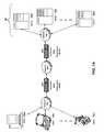
- FIG. 1Ais a block diagram of an embodiment of a network environment for a client to access a server via one or more network optimization appliances;
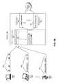
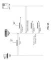
- FIG. 1Bis a block diagram of another embodiment of a network environment for a client to access a server via one or more network optimization appliances in conjunction with other network appliances;
- FIG. 1Cis a block diagram of another embodiment of a network environment for a client to access a server via a single network optimization appliance deployed stand-alone or in conjunction with other network appliances;
- FIGS. 1D and 1Eare block diagrams of embodiments of a computing device
- FIG. 2Ais a block diagram of an embodiment of an appliance for processing communications between a client and a server;
- FIG. 2Bis a block diagram of another embodiment of a client and/or server deploying the network optimization features of the appliance
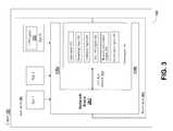
- FIG. 3is a block diagram of an embodiment of a client for communicating with a server using the network optimization feature
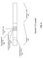
- FIG. 4is a block diagram of a sample TCP packet
- FIG. 4illustrates a sample TCP packet
- FIG. 5is an illustration of a number of clients transmitting packet groups which may classified as transactions
- FIG. 6is a flow diagram of a method for prioritizing, based on transaction size, packets awaiting transmission from an intermediary device
- FIGS. 7A and 7Bdepict systems and methods for using transaction boundaries to reduce timeout penalties
- FIGS. 8A and 8Bdepict systems and methods for retransmitting network packets between a sender and a receiver to reduce retransmission costs associated with a transport layer connection
- the network environmenthas one or more clients 102 a - 102 n (also generally referred to as local machine(s) 102 , or client(s) 102 ) in communication with one or more servers 106 a - 106 n (also generally referred to as server(s) 106 , or remote machine(s) 106 ) via one or more networks 104 , 104 ′, 104 ′′.
- clients 102 a - 102 nalso generally referred to as local machine(s) 102 , or client(s) 102
- servers 106 a - 106 nalso generally referred to as server(s) 106 , or remote machine(s) 106
- a client 102communicates with a server 106 via one or more network optimization appliances 200 , 200 ′ (generally referred to as appliance 200 ).
- the network optimization appliance 200is designed, configured or adapted to optimize Wide Area Network (WAN) network traffic.
- WANWide Area Network
- a first appliance 200works in conjunction or cooperation with a second appliance 200 ′ to optimize network traffic.
- a first appliance 200may be located between a branch office and a WAN connection while the second appliance 200 ′ is located between the WAN and a corporate Local Area Network (LAN).
- the appliances 200 and 200 ′may work together to optimize the WAN related network traffic between a client in the branch office and a server on the corporate LAN.
- FIG. 1Ashows a network 104 , network 104 ′ and network 104 ′′ (generally referred to as network(s) 104 ) between the clients 102 and the servers 106
- the networks 104 , 104 ′, 104 ′′can be the same type of network or different types of networks.
- the network 104can be a local-area network (LAN), such as a company Intranet, a metropolitan area network (MAN), or a wide area network (WAN), such as the Internet or the World Wide Web.
- the networks 104 , 104 ′, 104 ′′can be a private or public network.
- network 104 ′ or network 104 ′′may be a private network and network 104 may be a public network.
- network 104may be a private network and network 104 ′ and/or network 104 ′′ a public network.
- networks 104 , 104 ′, 104 ′′may be private networks.
- clients 102may be located at a branch office of a corporate enterprise communicating via a WAN connection over the network 104 to the servers 106 located on a corporate LAN in a corporate data center.
- the network 104may be any type and/or form of network and may include any of the following: a point to point network, a broadcast network, a wide area network, a local area network, a telecommunications network, a data communication network, a computer network, an ATM (Asynchronous Transfer Mode) network, a SONET (Synchronous Optical Network) network, a SDH (Synchronous Digital Hierarchy) network, a wireless network and a wireline network.
- the network 104may comprise a wireless link, such as an infrared channel or satellite band.
- the topology of the network 104may be a bus, star, or ring network topology.
- the network 104 and network topologymay be of any such network or network topology as known to those ordinarily skilled in the art capable of supporting the operations described herein.
- a first network optimization appliance 200is shown between networks 104 and 104 ′ and a second network optimization appliance 200 ′ is also between networks 104 ′ and 104 ′′.
- the appliance 200may be located on network 104 .
- a corporate enterprisemay deploy an appliance 200 at the branch office.
- the appliance 200may be located on network 104 ′.
- the appliance 200 ′may be located on network 104 ′ or network 104 ′′.
- an appliance 200may be located at a corporate data center.
- the appliance 200 and 200 ′are on the same network.
- the appliance 200 and 200 ′are on different networks.
- the appliance 200is a device for accelerating, optimizing or otherwise improving the performance, operation, or quality of service of any type and form of network traffic.
- the appliance 200is a performance enhancing proxy.
- the appliance 200is any type and form of WAN optimization or acceleration device, sometimes also referred to as a WAN optimization controller.
- the appliance 200is any of the product embodiments referred to as WANScaler manufactured by Citrix Systems, Inc. of Ft. Lauderdale, Fla.
- the appliance 200includes any of the product embodiments referred to as BIG-IP link controller and WANjet manufactured by F5 Networks, Inc. of Seattle, Wash.
- the appliance 200includes any of the WX and WXC WAN acceleration device platforms manufactured by Juniper Networks, Inc. of Sunnyvale, Calif. In some embodiments, the appliance 200 includes any of the steelhead line of WAN optimization appliances manufactured by Riverbed Technology of San Francisco, Calif. In other embodiments, the appliance 200 includes any of the WAN related devices manufactured by Expand Networks Inc. of Roseland, N.J. In one embodiment, the appliance 200 includes any of the WAN related appliances manufactured by Packeteer Inc. of Cupertino, Calif., such as the PacketShaper, iShared, and SkyX product embodiments provided by Packeteer. In yet another embodiment, the appliance 200 includes any WAN related appliances and/or software manufactured by Cisco Systems, Inc. of San Jose, Calif., such as the Cisco Wide Area Network Application Services software and network modules, and Wide Area Network engine appliances.
- the appliance 200provides application and data acceleration services for branch-office or remote offices.
- the appliance 200includes optimization of Wide Area File Services (WAFS).
- WAFSWide Area File Services
- the appliance 200accelerates the delivery of files, such as via the Common Internet File System (CIFS) protocol.
- CIFSCommon Internet File System
- the appliance 200provides caching in memory and/or storage to accelerate delivery of applications and data.
- the appliance 205provides compression of network traffic at any level of the network stack or at any protocol or network layer.
- the appliance 200provides transport layer protocol optimizations, flow control, performance enhancements or modifications and/or management to accelerate delivery of applications and data over a WAN connection.
- the appliance 200provides Transport Control Protocol (TCP) optimizations.
- TCPTransport Control Protocol
- the appliance 200provides optimizations, flow control, performance enhancements or modifications and/or management for any session or application layer protocol. Further details of the optimization techniques, operations and architecture of the appliance 200 are discussed below in Section B.
- the network environmentmay include multiple, logically-grouped servers 106 .
- the logical group of serversmay be referred to as a server farm 38 .
- the servers 106may be geographically dispersed.
- a farm 38may be administered as a single entity.
- the server farm 38comprises a plurality of server farms 38 .
- the server farmexecutes one or more applications on behalf of one or more clients 102 .
- the servers 106 within each farm 38can be heterogeneous. One or more of the servers 106 can operate according to one type of operating system platform (e.g., WINDOWS NT, manufactured by Microsoft Corp. of Redmond, Wash.), while one or more of the other servers 106 can operate on according to another type of operating system platform (e.g., Unix or Linux).
- the servers 106 of each farm 38do not need to be physically proximate to another server 106 in the same farm 38 .
- the group of servers 106 logically grouped as a farm 38may be interconnected using a wide-area network (WAN) connection or metropolitan-area network (MAN) connection.
- WANwide-area network
- MANmetropolitan-area network
- a farm 38may include servers 106 physically located in different continents or different regions of a continent, country, state, city, campus, or room. Data transmission speeds between servers 106 in the farm 38 can be increased if the servers 106 are connected using a local-area network (LAN) connection or some form of direct connection.
- LANlocal-area network
- Servers 106may be file servers, application servers, web servers, proxy servers, and/or gateway servers.
- a server 106may have the capacity to function as either an application server or as a master application server.
- a server 106may include an Active Directory.
- the clients 102may also be referred to as client nodes or endpoints.
- a client 102has the capacity to function as both a client node seeking access to applications on a server and as an application server providing access to hosted applications for other clients 102 a - 102 n.
- a client 102communicates with a server 106 .
- the client 102communicates directly with one of the servers 106 in a farm 38 .
- the client 102executes a program neighborhood application to communicate with a server 106 in a farm 38 .
- the server 106provides the functionality of a master node.
- the client 102communicates with the server 106 in the farm 38 through a network 104 . Over the network 104 , the client 102 can, for example, request execution of various applications hosted by the servers 106 a - 106 n in the farm 38 and receive output of the results of the application execution for display.
- only the master nodeprovides the functionality required to identify and provide address information associated with a server 106 ′ hosting a requested application.
- a server 106provides functionality of a web server.
- the server 106 areceives requests from the client 102 , forwards the requests to a second server 106 b and responds to the request by the client 102 with a response to the request from the server 106 b .
- the server 106acquires an enumeration of applications available to the client 102 and address information associated with a server 106 hosting an application identified by the enumeration of applications.
- the server 106presents the response to the request to the client 102 using a web interface.
- the client 102communicates directly with the server 106 to access the identified application.
- the client 102receives application output data, such as display data, generated by an execution of the identified application on the server 106 .
- FIG. 1Banother embodiment of a network environment is depicted in which the network optimization appliance 200 is deployed with one or more other appliances 205 , 205 ′ (generally referred to as appliance 205 or second appliance 205 ) such as a gateway, firewall or acceleration appliance.
- appliance 205is a firewall or security appliance while appliance 205 ′ is a LAN acceleration device.
- a client 102may communicate to a server 106 via one or more of the first appliances 200 and one or more second appliances 205 .
- One or more appliances 200 and 205may be located at any point in the network or network communications path between a client 102 and a server 106 .
- a second appliance 205may be located on the same network 104 as the first appliance 200 .
- the second appliance 205may be located on a different network 104 as the first appliance 200 .
- a first appliance 200 and second appliance 205is on the same network, for example network 104
- the first appliance 200 ′ and second appliance 205 ′is on the same network, such as network 104 ′′.
- the second appliance 205includes any type and form of transport control protocol or transport later terminating device, such as a gateway or firewall device.
- the appliance 205terminates the transport control protocol by establishing a first transport control protocol connection with the client and a second transport control connection with the second appliance or server.
- the appliance 205terminates the transport control protocol by changing, managing or controlling the behavior of the transport control protocol connection between the client and the server or second appliance. For example, the appliance 205 may change, queue, forward or transmit network packets in manner to effectively terminate the transport control protocol connection or to act or simulate as terminating the connection.
- the second appliance 205is a performance enhancing proxy.
- the appliance 205provides a virtual private network (VPN) connection.
- the appliance 205provides a Secure Socket Layer VPN (SSL VPN) connection.
- the appliance 205provides an IPsec (Internet Protocol Security) based VPN connection.
- the appliance 205provides any one or more of the following functionality: compression, acceleration, load-balancing, switching/routing, caching, and Transport Control Protocol (TCP) acceleration.
- VPNvirtual private network
- SSL VPNSecure Socket Layer VPN
- IPsecInternet Protocol Security
- TCPTransport Control Protocol
- the appliance 205is any of the product embodiments referred to as Access Gateway, Application Firewall, Application Gateway, or NetScaler manufactured by Citrix Systems, Inc. of Ft. Lauderdale, Fla. As such, in some embodiments, the appliance 205 includes any logic, functions, rules, or operations to perform services or functionality such as SSL VPN connectivity, SSL offloading, switching/load balancing, Domain Name Service resolution, LAN acceleration and an application firewall.
- the appliance 205provides a SSL VPN connection between a client 102 and a server 106 .
- a client 102 on a first network 104requests to establish a connection to a server 106 on a second network 104 ′.
- the second network 104 ′′is not routable from the first network 104 .
- the client 102is on a public network 104 and the server 106 is on a private network 104 ′, such as a corporate network.
- a client agentintercepts communications of the client 102 on the first network 104 , encrypts the communications, and transmits the communications via a first transport layer connection to the appliance 205 .
- the appliance 205associates the first transport layer connection on the first network 104 to a second transport layer connection to the server 106 on the second network 104 .
- the appliance 205receives the intercepted communication from the client agent, decrypts the communications, and transmits the communication to the server 106 on the second network 104 via the second transport layer connection.
- the second transport layer connectionmay be a pooled transport layer connection.
- the appliance 205provides an end-to-end secure transport layer connection for the client 102 between the two networks 104 , 104 ′
- the appliance 205hosts an intranet internet protocol or intranetIP address of the client 102 on the virtual private network 104 .
- the client 102has a local network identifier, such as an internet protocol (IP) address and/or host name on the first network 104 .
- IPinternet protocol
- the appliance 205When connected to the second network 104 ′ via the appliance 205 , the appliance 205 establishes, assigns or otherwise provides an IntranetIP, which is a network identifier, such as IP address and/or host name, for the client 102 on the second network 104 ′.
- the appliance 205listens for and receives on the second or private network 104 ′ for any communications directed towards the client 102 using the client's established IntranetIP.
- the appliance 205acts as or on behalf of the client 102 on the second private network 104 .
- the appliance 205has an encryption engine providing logic, business rules, functions or operations for handling the processing of any security related protocol, such as SSL or TLS, or any function related thereto.
- the encryption engineencrypts and decrypts network packets, or any portion thereof, communicated via the appliance 205 .
- the encryption enginemay also setup or establish SSL or TLS connections on behalf of the client 102 a - 102 n , server 106 a - 106 n , or appliance 200 , 205 .
- the encryption engineprovides offloading and acceleration of SSL processing.
- the encryption engineuses a tunneling protocol to provide a virtual private network between a client 102 a - 102 n and a server 106 a - 106 n .
- the encryption engineuses an encryption processor.
- the encryption engineincludes executable instructions running on an encryption processor.
- the appliance 205provides one or more of the following acceleration techniques to communications between the client 102 and server 106 : 1) compression, 2) decompression, 3) Transmission Control Protocol pooling, 4) Transmission Control Protocol multiplexing, 5) Transmission Control Protocol buffering, and 6) caching.
- the appliance 200relieves servers 106 of much of the processing load caused by repeatedly opening and closing transport layers connections to clients 102 by opening one or more transport layer connections with each server 106 and maintaining these connections to allow repeated data accesses by clients via the Internet. This technique is referred to herein as “connection pooling”.
- the appliance 205in order to seamlessly splice communications from a client 102 to a server 106 via a pooled transport layer connection, the appliance 205 translates or multiplexes communications by modifying sequence number and acknowledgment numbers at the transport layer protocol level. This is referred to as “connection multiplexing”. In some embodiments, no application layer protocol interaction is required. For example, in the case of an in-bound packet (that is, a packet received from a client 102 ), the source network address of the packet is changed to that of an output port of appliance 205 , and the destination network address is changed to that of the intended server.
- the source network addressis changed from that of the server 106 to that of an output port of appliance 205 and the destination address is changed from that of appliance 205 to that of the requesting client 102 .
- the sequence numbers and acknowledgment numbers of the packetare also translated to sequence numbers and acknowledgement expected by the client 102 on the appliance's 205 transport layer connection to the client 102 .
- the packet checksum of the transport layer protocolis recalculated to account for these translations.
- the appliance 205provides switching or load-balancing functionality for communications between the client 102 and server 106 .
- the appliance 205distributes traffic and directs client requests to a server 106 based on layer 4 payload or application-layer request data.
- the appliance 205determines the server 106 to distribute the network packet by application information and data carried as payload of the transport layer packet.
- a health monitoring program of the appliance 205monitors the health of servers to determine the server 106 for which to distribute a client's request.
- the appliance 205can direct or distribute client requests to another server 106 .
- the appliance 205acts as a Domain Name Service (DNS) resolver or otherwise provides resolution of a DNS request from clients 102 .
- DNSDomain Name Service
- the applianceintercepts' a DNS request transmitted by the client 102 .
- the appliance 205responds to a client's DNS request with an IP address of or hosted by the appliance 205 .
- the client 102transmits network communication for the domain name to the appliance 200 .
- the appliance 200responds to a client's DNS request with an IP address of or hosted by a second appliance 200 ′.
- the appliance 205responds to a client's DNS request with an IP address of a server 106 determined by the appliance 200 .
- the appliance 205provides application firewall functionality for communications between the client 102 and server 106 .
- a policy engine 295 ′provides rules for detecting and blocking illegitimate requests.
- the application firewallprotects against denial of service (DoS) attacks.
- the applianceinspects the content of intercepted requests to identify and block application-based attacks.
- DoSdenial of service
- the rules/policy engineincludes one or more application firewall or security control policies for providing protections against various classes and types of web or Internet based vulnerabilities, such as one or more of the following: 1) buffer overflow, 2) CGI-BIN parameter manipulation, 3) form/hidden field manipulation, 4) forceful browsing, 5) cookie or session poisoning, 6) broken access control list (ACLs) or weak passwords, 7) cross-site scripting (XSS), 8) command injection, 9) SQL injection, 10) error triggering sensitive information leak, 11) insecure use of cryptography, 12) server misconfiguration, 13) back doors and debug options, 14) website defacement, 15) platform or operating systems vulnerabilities, and 16) zero-day exploits.
- application firewall or security control policiesfor providing protections against various classes and types of web or Internet based vulnerabilities, such as one or more of the following: 1) buffer overflow, 2) CGI-BIN parameter manipulation, 3) form/hidden field manipulation, 4) forceful browsing, 5) cookie or session poisoning, 6) broken access control list (ACL
- the application firewall of the applianceprovides HTML form field protection in the form of inspecting or analyzing the network communication for one or more of the following: 1) required fields are returned, 2) no added field allowed, 3) read-only and hidden field enforcement, 4) drop-down list and radio button field conformance, and 5) form-field max-length enforcement.
- the application firewall of the appliance 205ensures cookies are not modified. In other embodiments, the appliance 205 protects against forceful browsing by enforcing legal URLs.
- the application firewall appliance 205protects any confidential information contained in the network communication.
- the appliance 205may inspect or analyze any network communication in accordance with the rules or polices of the policy engine to identify any confidential information in any field of the network packet.
- the application firewallidentifies in the network communication one or more occurrences of a credit card number, password, social security number, name, patient code, contact information, and age.
- the encoded portion of the network communicationmay include these occurrences or the confidential information.
- the application firewallmay take a policy action on the network communication, such as prevent transmission of the network communication.
- the application firewallmay rewrite, remove or otherwise mask such identified occurrence or confidential information.
- the first appliance 200 and second appliance 205may be the same type and form of appliance.
- the second appliance 205may perform the same functionality, or portion thereof, as the first appliance 200 , and vice-versa.
- the first appliance 200 and second appliance 205may both provide acceleration techniques.
- the first appliancemay perform LAN acceleration while the second appliance performs WAN acceleration, or vice-versa.
- the first appliance 200may also be a transport control protocol terminating device as with the second appliance 205 .
- appliances 200 and 205are shown as separate devices on the network, the appliance 200 and/or 205 could be a part of any client 102 or server 106 .
- the appliance 200may be deployed as a single appliance or single proxy on the network 104 .
- the appliance 200may be designed, constructed or adapted to perform WAN optimization techniques discussed herein without a second cooperating appliance 200 ′.
- a single appliance 200may be deployed with one or more second appliances 205 .
- a WAN acceleration first appliance 200such as a Citrix WANScaler appliance
- a LAN accelerating or Application Firewall second appliance 205such as a Citrix NetScaler appliance.
- FIGS. 1C and 1Ddepict block diagrams of a computing device 100 useful for practicing an embodiment of the client 102 , server 106 or appliance 200 .
- each computing device 100includes a central processing unit 101 , and a main memory unit 122 .
- a computing device 100may include a visual display device 124 , a keyboard 126 and/or a pointing device 127 , such as a mouse.
- Each computing device 100may also include additional optional elements, such as one or more input/output devices 130 a - 130 b (generally referred to using reference numeral 130 ), and a cache memory 140 in communication with the central processing unit 101 .
- the central processing unit 101is any logic circuitry that responds to and processes instructions fetched from the main memory unit 122 .
- the central processing unitis provided by a microprocessor unit, such as: those manufactured by Intel Corporation of Mountain View, Calif.; those manufactured by Motorola Corporation of Schaumburg, Ill.; those manufactured by Transmeta Corporation of Santa Clara, Calif.; the RS/6000 processor, those manufactured by International Business Machines of White Plains, N.Y.; or those manufactured by Advanced Micro Devices of Sunnyvale, Calif.
- the computing device 100may be based on any of these processors, or any other processor capable of operating as described herein.
- Main memory unit 122may be one or more memory chips capable of storing data and allowing any storage location to be directly accessed by the microprocessor 101 , such as Static random access memory (SRAM), Burst SRAM or SynchBurst SRAM (BSRAM), Dynamic random access memory (DRAM), Fast Page Mode DRAM (FPM DRAM), Enhanced DRAM (EDRAM), Extended Data Output RAM (EDO RAM), Extended Data Output DRAM (EDO DRAM), Burst Extended Data Output DRAM (BEDO DRAM), Enhanced DRAM (EDRAM), synchronous DRAM (SDRAM), JEDEC SRAM, PC 100 SDRAM, Double Data Rate SDRAM (DDR SDRAM), Enhanced SDRAM (ESDRAM), SyncLink DRAM (SLDRAM), Direct Rambus DRAM (DRDRAM), or Ferroelectric RAM (FRAM).
- SRAMStatic random access memory
- BSRAMSynchBurst SRAM
- DRAMDynamic random access memory
- FPM DRAMFast Page Mode DRAM
- EDRAMEnhanced D
- the main memory 122may be based on any of the above described memory chips, or any other available memory chips capable of operating as described herein.
- the processor 101communicates with main memory 122 via a system bus 150 (described in more detail below).
- FIG. 1Cdepicts an embodiment of a computing device 100 in which the processor communicates directly with main memory 122 via a memory port 103 .
- the main memory 122may be DRDRAM.
- FIG. 1Ddepicts an embodiment in which the main processor 101 communicates directly with cache memory 140 via a secondary bus, sometimes referred to as a backside bus.
- the main processor 101communicates with cache memory 140 using the system bus 150 .
- Cache memory 140typically has a faster response time than main memory 122 and is typically provided by SRAM, BSRAM, or EDRAM.
- the processor 101communicates with various I/O devices 130 via a local system bus 150 .
- FIG. 1Ddepicts an embodiment of a computer 100 in which the main processor 101 communicates directly with I/O device 130 via HyperTransport, Rapid I/O, or InfiniBand.
- FIG. 1Dalso depicts an embodiment in which local busses and direct communication are mixed: the processor 101 communicates with I/O device 130 using a local interconnect bus while communicating with I/O device 130 directly.
- the computing device 100may support any suitable installation device 116 , such as a floppy disk drive for receiving floppy disks such as 3.5-inch, 5.25-inch disks or ZIP disks, a CD-ROM drive, a CD-R/RW drive, a DVD-ROM drive, tape drives of various formats, USB device, hard-drive or any other device suitable for installing software and programs such as any client agent 120 , or portion thereof.
- the computing device 100may further comprise a storage device 128 , such as one or more hard disk drives or redundant arrays of independent disks, for storing an operating system and other related software, and for storing application software programs such as any program related to the client agent 120 .
- any of the installation devices 116could also be used as the storage device 128 .
- the operating system and the softwarecan be run from a bootable medium, for example, a bootable CD, such as KNOPPIX®, a bootable CD for GNU/Linux that is available as a GNU/Linux distribution from knoppix.net.
- a bootable CDsuch as KNOPPIX®
- KNOPPIX®a bootable CD for GNU/Linux that is available as a GNU/Linux distribution from knoppix.net.
- the computing device 100may include a network interface 118 to interface to a Local Area Network (LAN), Wide Area Network (WAN) or the Internet through a variety of connections including, but not limited to, standard telephone lines, LAN or WAN links (e.g., 802.11, T1, T3, 56 kb, X.25), broadband connections (e.g., ISDN, Frame Relay, ATM), wireless connections, or some combination of any or all of the above.
- the network interface 118may comprise a built-in network adapter, network interface card, PCMCIA network card, card bus network adapter, wireless network adapter, USB network adapter, modem or any other device suitable for interfacing the computing device 100 to any type of network capable of communication and performing the operations described herein.
- I/O devices 130 a - 130 nmay be present in the computing device 100 .
- Input devicesinclude keyboards, mice, trackpads, trackballs, microphones, and drawing tablets.
- Output devicesinclude video displays, speakers, inkjet printers, laser printers, and dye-sublimation printers.
- the I/O devices 130may be controlled by an I/O controller 123 as shown in FIG. 1C .
- the I/O controllermay control one or more I/O devices such as a keyboard 126 and a pointing device 127 , e.g., a mouse or optical pen.
- an I/O devicemay also provide storage 128 and/or an installation medium 116 for the computing device 100 .
- the computing device 100may provide USB connections to receive handheld USB storage devices such as the USB Flash Drive line of devices manufactured by Twintech Industry, Inc. of Los Alamitos, Calif.
- the computing device 100may comprise or be connected to multiple display devices 124 a - 124 n , which each may be of the same or different type and/or form.
- any of the I/O devices 130 a - 130 n and/or the I/O controller 123may comprise any type and/or form of suitable hardware, software, or combination of hardware and software to support, enable or provide for the connection and use of multiple display devices 124 a - 124 n by the computing device 100 .
- the computing device 100may include any type and/or form of video adapter, video card, driver, and/or library to interface, communicate, connect or otherwise use the display devices 124 a - 124 n .
- a video adaptermay comprise multiple connectors to interface to multiple display devices 124 a - 124 n .
- the computing device 100may include multiple video adapters, with each video adapter connected to one or more of the display devices 124 a - 124 n .
- any portion of the operating system of the computing device 100may be configured for using multiple displays 124 a - 124 n .
- one or more of the display devices 124 a - 124 nmay be provided by one or more other computing devices, such as computing devices 100 a and 100 b connected to the computing device 100 , for example, via a network.
- These embodimentsmay include any type of software designed and constructed to use another computer's display device as a second display device 124 a for the computing device 100 .
- a computing device 100may be configured to have multiple display devices 124 a - 124 n.
- an I/O device 130may be a bridge 170 between the system bus 150 and an external communication bus, such as a USB bus, an Apple Desktop Bus, an RS-232 serial connection, a SCSI bus, a FireWire bus, a FireWire 800 bus, an Ethernet bus, an AppleTalk bus, a Gigabit Ethernet bus, an Asynchronous Transfer Mode bus, a HIPPI bus, a Super HIPPI bus, a SerialPlus bus, a SCI/LAMP bus, a FibreChannel bus, or a Serial Attached small computer system interface bus.
- an external communication bussuch as a USB bus, an Apple Desktop Bus, an RS-232 serial connection, a SCSI bus, a FireWire bus, a FireWire 800 bus, an Ethernet bus, an AppleTalk bus, a Gigabit Ethernet bus, an Asynchronous Transfer Mode bus, a HIPPI bus, a Super HIPPI bus, a SerialPlus bus, a SCI/LAMP bus, a FibreChannel bus, or
- a computing device 100 of the sort depicted in FIGS. 1C and 1Dtypically operate under the control of operating systems, which control scheduling of tasks and access to system resources.
- the computing device 100can be running any operating system such as any of the versions of the Microsoft® Windows operating systems, the different releases of the Unix and Linux operating systems, any version of the Mac OS® or OS X for Macintosh computers, any embedded operating system, any real-time operating system, any open source operating system, any proprietary operating system, any operating systems for mobile computing devices, or any other operating system capable of running on the computing device and performing the operations described herein.
- Typical operating systemsinclude: WINDOWS 3.x, WINDOWS 95, WINDOWS 98, WINDOWS 2000, WINDOWS NT 3.51, WINDOWS NT 4.0, WINDOWS CE, WINDOWS 2003, WINDOWS XP, and WINDOWS VISTA all of which are manufactured by Microsoft Corporation of Redmond, Wash.; MacOS and OS X, manufactured by Apple Computer of Cupertino, Calif.; OS/2, manufactured by International Business Machines of Armonk, N.Y.; and Linux, a freely-available operating system distributed by Caldera Corp.
- Unix operating systemany type and/or form of a Unix operating system, (such as those versions of Unix referred to as Solaris/Sparc, Solaris/x86, AIX IBM, HP UX, and SGI (Silicon Graphics)), among others.
- the computing device 100may have different processors, operating systems, and input devices consistent with the device.
- the computer 100is a Treo 180 , 270 , 1060 , 600 or 650 smart phone manufactured by Palm, Inc.
- the Treo smart phoneis operated under the control of the PalmOS operating system and includes a stylus input device as well as a five-way navigator device.
- the computing device 100may be a WinCE or PocketPC device with an ARM (Advanced RISC Machine) type of processor.
- the computing device 100includes a Series 80 (Nokia 9500 or Nokia 9300) type of smart phone manufactured by Nokia of Finland, which may run the Symbian OS or EPOC mobile operating system manufactured by Symbian Software Limited of London, United Kingdom.
- the computing device 100may include a FOMA M100 brand smart phone manufactured by Motorola, Inc. of Schaumburg, Ill., and operating the EPOC or Symbian OS operating system.
- the computing device 100includes a Sony Ericsson P800, P900 or P910 Alpha model phone manufactured by Sony Ericsson Mobile Communications (USA) Inc. of Research Triangle Park, N.C.
- the computing device 100can be any workstation, desktop computer, laptop or notebook computer, server, handheld computer, mobile telephone, smart phone, any other computer, or other form of computing or telecommunications device that is capable of communication and that has sufficient processor power and memory capacity to perform the operations described herein.
- a server 106includes an application delivery system 290 for delivering a computing environment or an application and/or data file to one or more clients 102 .
- a client 102is in communication with a server 106 via network 104 and appliance 200 .
- the client 102may reside in a remote office of a company, e.g., a branch office, and the server 106 may reside at a corporate data center.
- the client 102has a client agent 120 , and a computing environment 215 .
- the computing environment 215may execute or operate an application that accesses, processes or uses a data file.
- the computing environment 215 , application and/or data filemay be delivered via the appliance 200 and/or the server 106 .
- the appliance 200accelerates delivery of a computing environment 215 , or any portion thereof, to a client 102 .
- the appliance 200accelerates the delivery of the computing environment 215 by the application delivery system 290 .
- the embodiments described hereinmay be used to accelerate delivery of a streaming application and data file processable by the application from a central corporate data center to a remote user location, such as a branch office of the company.
- the appliance 200accelerates transport layer traffic between a client 102 and a server 106 .
- the appliance 200controls, manages, or adjusts the transport layer protocol to accelerate delivery of the computing environment.
- the appliance 200uses caching and/or compression techniques to accelerate delivery of a computing environment.
- the application delivery management system 290provides application delivery techniques to deliver a computing environment to a desktop of a user, remote or otherwise, based on a plurality of execution methods and based on any authentication and authorization policies applied via a policy engine 295 . With these techniques, a remote user may obtain a computing environment and access to server stored applications and data files from any network connected device 100 .
- the application delivery system 290may reside or execute on a server 106 . In another embodiment, the application delivery system 290 may reside or execute on a plurality of servers 106 a - 106 n . In some embodiments, the application delivery system 290 may execute in a server farm 38 .
- the server 106 executing the application delivery system 290may also store or provide the application and data file.
- a first set of one or more servers 106may execute the application delivery system 290
- a different server 106 nmay store or provide the application and data file.
- each of the application delivery system 290 , the application, and data filemay reside or be located on different servers.
- any portion of the application delivery system 290may reside, execute or be stored on or distributed to the appliance 200 , or a plurality of appliances.
- the client 102may include a computing environment 215 for executing an application that uses or processes a data file.
- the client 102 via networks 104 , 104 ′ and appliance 200may request an application and data file from the server 106 .
- the appliance 200may forward a request from the client 102 to the server 106 .
- the client 102may not have the application and data file stored or accessible locally.
- the application delivery system 290 and/or server 106may deliver the application and data file to the client 102 .
- the server 106may transmit the application as an application stream to operate in computing environment 215 on client 102 .
- the application delivery system 290comprises any portion of the Citrix Access SuiteTM by Citrix Systems, Inc., such as the MetaFrame or Citrix Presentation ServerTM and/or any of the Microsoft® Windows Terminal Services manufactured by the Microsoft Corporation.
- the application delivery system 290may deliver one or more applications to clients 102 or users via a remote-display protocol or otherwise via remote-based or server-based computing.
- the application delivery system 290may deliver one or more applications to clients or users via steaming of the application.
- the application delivery system 290includes a policy engine 295 for controlling and managing the access to applications, selection of application execution methods and the delivery of applications.
- the policy engine 295determines the one or more applications a user or client 102 may access.
- the policy engine 295determines how the application should be delivered to the user or client 102 , e.g., the method of execution.
- the application delivery system 290provides a plurality of delivery techniques from which to select a method of application execution, such as a server-based computing, streaming or delivering the application locally to the client 120 for local execution.
- a client 102requests execution of an application program and the application delivery system 290 comprising a server 106 selects a method of executing the application program.
- the server 106receives credentials from the client 102 .
- the server 106receives a request for an enumeration of available applications from the client 102 .
- the application delivery system 290enumerates a plurality of application programs available to the client 102 .
- the application delivery system 290receives a request to execute an enumerated application.
- the application delivery system 290selects one of a predetermined number of methods for executing the enumerated application, for example, responsive to a policy of a policy engine.
- the application delivery system 290may select a method of execution of the application enabling the client 102 to receive application-output data generated by execution of the application program on a server 106 .
- the application delivery system 290may select a method of execution of the application enabling the client or local machine 102 to execute the application program locally after retrieving a plurality of application files comprising the application.
- the application delivery system 290may select a method of execution of the application to stream the application via the network 104 to the client 102 .
- a client 102may execute, operate or otherwise provide an application, which can be any type and/or form of software, program, or executable instructions such as any type and/or form of web browser, web-based client, client-server application, a thin-client computing client, an ActiveX control, or a Java applet, or any other type and/or form of executable instructions capable of executing on client 102 .
- the applicationmay be a server-based or a remote-based application executed on behalf of the client 102 on a server 106 .
- the server 106may display output to the client 102 using any thin-client or remote-display protocol, such as the Independent Computing Architecture (ICA) protocol manufactured by Citrix Systems, Inc. of Ft. Lauderdale, Fla.
- ICAIndependent Computing Architecture
- the applicationcan use any type of protocol and it can be, for example, an HTTP client, an FTP client, an Oscar client, or a Telnet client.
- the applicationcomprises any type of software related to VoIP communications, such as a soft IP telephone.
- the applicationcomprises any application related to real-time data communications, such as applications for streaming video and/or audio.
- the server 106 or a server farm 38may be running one or more applications, such as an application providing a thin-client computing or remote display presentation application.
- the server 106 or server farm 38executes, as an application, any portion of the Citrix Access SuiteTM by Citrix Systems, Inc., such as the MetaFrame or Citrix Presentation ServerTM, and/or any of the Microsoft® Windows Terminal Services manufactured by the Microsoft Corporation.
- the applicationis an ICA client, developed by Citrix Systems, Inc. of Fort Lauderdale, Fla.
- the applicationincludes a Remote Desktop (RDP) client, developed by Microsoft Corporation of Redmond, Wash.
- RDPRemote Desktop
- the server 106may run an application, which for example, may be an application server providing email services such as Microsoft Exchange manufactured by the Microsoft Corporation of Redmond, Wash., a web or Internet server, or a desktop sharing server, or a collaboration server.
- any of the applicationsmay comprise any type of hosted service or products, such as GoToMeetingTM provided by Citrix Online Division, Inc. of Santa Barbara, Calif., WebExTM provided by WebEx, Inc. of Santa Clara, Calif., or Microsoft Office Live Meeting provided by Microsoft Corporation of Redmond, Wash.
- FIG. 2Aalso illustrates an example embodiment of the appliance 200 .
- the architecture of the appliance 200 in FIG. 2Ais provided by way of illustration only and is not intended to be limiting in any manner.
- the appliance 200may include any type and form of computing device 100 , such as any element or portion described in conjunction with FIGS. 1D and 1E above.
- the appliance 200has one or more network ports 266 A- 226 N and one or more networks stacks 267 A- 267 N for receiving and/or transmitting communications via networks 104 .
- the appliance 200also has a network optimization engine 250 for optimizing, accelerating or otherwise improving the performance, operation, or quality of any network traffic or communications traversing the appliance 200 .
- the appliance 200includes or is under the control of an operating system.
- the operating system of the appliance 200may be any type and/or form of Unix operating system although the invention is not so limited.
- the appliance 200can be running any operating system such as any of the versions of the Microsoft® Windows operating systems, the different releases of the Unix and Linux operating systems, any version of the Mac OS® for Macintosh computers, any embedded operating system, any network operating system, any real-time operating system, any open source operating system, any proprietary operating system, any operating systems for mobile computing devices or network devices, or any other operating system capable of running on the appliance 200 and performing the operations described herein.
- the operating system of appliance 200allocates, manages, or otherwise segregates the available system memory into what is referred to as kernel or system space, and user or application space.
- the kernel spaceis typically reserved for running the kernel, including any device drivers, kernel extensions or other kernel related software.
- the kernelis the core of the operating system, and provides access, control, and management of resources and hardware-related elements of the appliance 200 .
- the kernel spacealso includes a number of network services or processes working in conjunction with the network optimization engine 250 , or any portion thereof. Additionally, the embodiment of the kernel will depend on the embodiment of the operating system installed, configured, or otherwise used by the device 200 .
- user spaceis the memory area or portion of the operating system used by user mode applications or programs otherwise running in user mode.
- a user mode applicationmay not access kernel space directly and uses service calls in order to access kernel services.
- the operating systemuses the user or application space for executing or running applications and provisioning of user level programs, services, processes and/or tasks.
- the appliance 200has one or more network ports 266 for transmitting and receiving data over a network 104 .
- the network port 266provides a physical and/or logical interface between the computing device and a network 104 or another device 100 for transmitting and receiving network communications.
- the type and form of network port 266depends on the type and form of network and type of medium for connecting to the network.
- any software of, provisioned for or used by the network port 266 and network stack 267may run in either kernel space or user space.
- the appliance 200has one network stack 267 , such as a TCP/IP based stack, for communicating on a network 105 , such with the client 102 and/or the server 106 .
- the network stack 267is used to communicate with a first network, such as network 104 , and also with a second network 104 ′.
- the appliance 200has two or more network stacks, such as first network stack 267 A and a second network stack 267 N.
- the first network stack 267 Amay be used in conjunction with a first port 266 A to communicate on a first network 104 .
- the second network stack 267 Nmay be used in conjunction with a second port 266 N to communicate on a second network 104 ′.
- the network stack(s) 267has one or more buffers for queuing one or more network packets for transmission by the appliance 200 .
- the network stack 267includes any type and form of software, or hardware, or any combinations thereof, for providing connectivity to and communications with a network.
- the network stack 267includes a software implementation for a network protocol suite.
- the network stack 267may have one or more network layers, such as any networks layers of the Open Systems Interconnection (OSI) communications model as those skilled in the art recognize and appreciate.
- OSIOpen Systems Interconnection
- the network stack 267may have any type and form of protocols for any of the following layers of the OSI model: 1) physical link layer, 2) data link layer, 3) network layer, 4) transport layer, 5) session layer, 6) presentation layer, and 7) application layer.
- the network stack 267includes a transport control protocol (TCP) over the network layer protocol of the internet protocol (IP), generally referred to as TCP/IP.
- TCP/IPtransport control protocol
- IPinternet protocol
- the TCP/IP protocolmay be carried over the Ethernet protocol, which may comprise any of the family of IEEE wide-area-network (WAN) or local-area-network (LAN) protocols, such as those protocols covered by the IEEE 802.3.
- the network stack 267has any type and form of a wireless protocol, such as IEEE 802.11 and/or mobile internet protocol.
- any TCP/IP based protocolmay be used, including Messaging Application Programming Interface (MAPI) (email), File Transfer Protocol (FTP), HyperText Transfer Protocol (HTTP), Common Internet File System (CIFS) protocol (file transfer), Independent Computing Architecture (ICA) protocol, Remote Desktop Protocol (RDP), Wireless Application Protocol (WAP), Mobile IP protocol, and Voice Over IP (VoIP) protocol.
- MAPIMessaging Application Programming Interface
- FTPFile Transfer Protocol
- HTTPHyperText Transfer Protocol
- CIFSCommon Internet File System
- ICAIndependent Computing Architecture
- RDPRemote Desktop Protocol
- WAPWireless Application Protocol
- VoIPVoice Over IP
- the network stack 267comprises any type and form of transport control protocol, such as a modified transport control protocol, for example a Transaction TCP (T/TCP), TCP with selection acknowledgements (TCP-SACK), TCP with large windows (TCP-LW), a congestion prediction protocol such as the TCP-Vegas protocol, and a TCP spoofing protocol.
- a modified transport control protocolfor example a Transaction TCP (T/TCP), TCP with selection acknowledgements (TCP-SACK), TCP with large windows (TCP-LW), a congestion prediction protocol such as the TCP-Vegas protocol, and a TCP spoofing protocol.
- T/TCPTransaction TCP
- TCP-SACKTCP with selection acknowledgements
- TCP-LWTCP with large windows
- congestion prediction protocolsuch as the TCP-Vegas protocol
- TCP spoofing protocola congestion prediction protocol
- UDPuser datagram protocol
- the network stack 267may include one or more network drivers supporting the one or more layers, such as a TCP driver or a network layer driver.
- the network driversmay be included as part of the operating system of the computing device 100 or as part of any network interface cards or other network access components of the computing device 100 .
- any of the network drivers of the network stack 267may be customized, modified or adapted to provide a custom or modified portion of the network stack 267 in support of any of the techniques described herein.
- the appliance 200provides for or maintains a transport layer connection between a client 102 and server 106 using a single network stack 267 .
- the appliance 200effectively terminates the transport layer connection by changing, managing or controlling the behavior of the transport control protocol connection between the client and the server.
- the appliance 200may use a single network stack 267 .
- the appliance 200terminates a first transport layer connection, such as a TCP connection of a client 102 , and establishes a second transport layer connection to a server 106 for use by or on behalf of the client 102 , e.g., the second transport layer connection is terminated at the appliance 200 and the server 106 .
- the first and second transport layer connectionsmay be established via a single network stack 267 .
- the appliance 200may use multiple network stacks, for example 267 A and 267 N.
- the first transport layer connectionmay be established or terminated at one network stack 267 A
- the second transport layer connectionmay be established or terminated on the second network stack 267 N.
- one network stackmay be for receiving and transmitting network packets on a first network
- another network stackfor receiving and transmitting network packets on a second network.
- the network optimization engine 250includes one or more of the following elements, components or modules: network packet processing engine 240 , LAN/WAN detector 210 , flow controller 220 , QoS engine 236 , protocol accelerator 234 , compression engine 238 , cache manager 232 and policy engine 295 ′.
- the network optimization engine 250may include software, hardware or any combination of software and hardware.
- any software of, provisioned for or used by the network optimization engine 250may run in either kernel space or user space.
- the network optimization engine 250may run in kernel space.
- the network optimization engine 250may run in user space.
- a first portion of the network optimization engine 250runs in kernel space while a second portion of the network optimization engine 250 runs in user space.
- the network packet engine 240also generally referred to as a packet processing engine or packet engine, is responsible for controlling and managing the processing of packets received and transmitted by appliance 200 via network ports 266 and network stack(s) 267 .
- the network packet engine 240may operate at any layer of the network stack 267 .
- the network packet engine 240operates at layer 2 or layer 3 of the network stack 267 .
- the packet engine 240intercepts or otherwise receives packets at the network layer, such as the IP layer in a TCP/IP embodiment.
- the packet engine 240operates at layer 4 of the network stack 267 .
- the packet engine 240intercepts or otherwise receives packets at the transport layer, such as intercepting packets as the TCP layer in a TCP/IP embodiment. In other embodiments, the packet engine 240 operates at any session or application layer above layer 4 . For example, in one embodiment, the packet engine 240 intercepts or otherwise receives network packets above the transport layer protocol layer, such as the payload of a TCP packet in a TCP embodiment.
- the packet engine 240may include a buffer for queuing one or more network packets during processing, such as for receipt of a network packet or transmission of a network packet. Additionally, the packet engine 240 is in communication with one or more network stacks 267 to send and receive network packets via network ports 266 .
- the packet engine 240may include a packet processing timer. In one embodiment, the packet processing timer provides one or more time intervals to trigger the processing of incoming, i.e., received, or outgoing, i.e., transmitted, network packets. In some embodiments, the packet engine 240 processes network packets responsive to the timer.
- the packet processing timerprovides any type and form of signal to the packet engine 240 to notify, trigger, or communicate a time related event, interval or occurrence. In many embodiments, the packet processing timer operates in the order of milliseconds, such as for example 100 ms, 50 ms, 25 ms, 10 ms, 5 ms or 1 ms.
- the packet engine 240may be interfaced, integrated or be in communication with any portion of the network optimization engine 250 , such as the LAN/WAN detector 210 , flow controller 220 , QoS engine 236 , protocol accelerator 234 , compression engine 238 , cache manager 232 and/or policy engine 295 ′.
- the network optimization engine 250such as the LAN/WAN detector 210 , flow controller 220 , QoS engine 236 , protocol accelerator 234 , compression engine 238 , cache manager 232 and/or policy engine 295 ′.
- any of the logic, functions, or operations of the LAN/WAN detector 210 , flow controller 220 , QoS engine 236 , protocol accelerator 234 , compression engine 238 , cache manager 232 and policy engine 295 'may be performed responsive to the packet processing timer and/or the packet engine 240 .
- any of the logic, functions, or operations of the encryption engine 234 , cache manager 232 , policy engine 236 and multi-protocol compression logic 238may be performed at the granularity of time intervals provided via the packet processing timer, for example, at a time interval of less than or equal to 10 ms.
- the cache manager 232may perform expiration of any cached objects responsive to the integrated packet engine 240 and/or the packet processing timer 242 .
- the expiry or invalidation time of a cached objectcan be set to the same order of granularity as the time interval of the packet processing timer, such as at every 10 ms.
- the cache manager 232may include software, hardware or any combination of software and hardware to store data, information and objects to a cache in memory or storage, provide cache access, and control and manage the cache.
- the data, objects or content processed and stored by the cache manager 232may include data in any format, such as a markup language, or any type of data communicated via any protocol.
- the cache manager 232duplicates original data stored elsewhere or data previously computed, generated or transmitted, in which the original data may require longer access time to fetch, compute or otherwise obtain relative to reading a cache memory or storage element. Once the data is stored in the cache, future use can be made by accessing the cached copy rather than refetching or recomputing the original data, thereby reducing the access time.
- the cachemay comprise a data object in memory of the appliance 200 .
- the cachemay comprise any type and form of storage element of the appliance 200 , such as a portion of a hard disk.
- the processing unit of the devicemay provide cache memory for use by the cache manager 232 .
- the cache manager 232may use any portion and combination of memory, storage, or the processing unit for caching data, objects, and other content.
- the cache manager 232includes any logic, functions, rules, or operations to perform any caching techniques of the appliance 200 .
- the cache manager 232may operate as an application, library, program, service, process, thread or task.
- the cache manager 232can comprise any type of general purpose processor (GPP), or any other type of integrated circuit, such as a Field Programmable Gate Array (FPGA), Programmable Logic Device (PLD), or Application Specific Integrated Circuit (ASIC).
- GPPgeneral purpose processor
- FPGAField Programmable Gate Array
- PLDProgrammable Logic Device
- ASICApplication Specific Integrated Circuit
- the policy engine 295 ′includes any logic, function or operations for providing and applying one or more policies or rules to the function, operation or configuration of any portion of the appliance 200 .
- the policy engine 295 ′may include, for example, an intelligent statistical engine or other programmable application(s).
- the policy engine 295provides a configuration mechanism to allow a user to identify, specify, define or configure a policy for the network optimization engine 250 , or any portion thereof.
- the policy engine 295may provide policies for what data to cache, when to cache the data, for whom to cache the data, when to expire an object in cache or refresh the cache.
- the policy engine 236may include any logic, rules, functions or operations to determine and provide access, control and management of objects, data or content being cached by the appliance 200 in addition to access, control and management of security, network traffic, network access, compression or any other function or operation performed by the appliance 200 .
- the policy engine 295 ′provides and applies one or more policies based on any one or more of the following: a user, identification of the client, identification of the server, the type of connection, the time of the connection, the type of network, or the contents of the network traffic.
- the policy engine 295 ′provides and applies a policy based on any field or header at any protocol layer of a network packet.
- the policy engine 295 ′provides and applies a policy based on any payload of a network packet.
- the policy engine 295 ′applies a policy based on identifying a certain portion of content of an application layer protocol carried as a payload of a transport layer packet.
- the policy engine 295 ′applies a policy based on any information identified by a client, server or user certificate. In yet another embodiment, the policy engine 295 ′ applies a policy based on any attributes or characteristics obtained about a client 102 , such as via any type and form of endpoint detection (see for example the collection agent of the client agent discussed below).
- the policy engine 295 ′works in conjunction or cooperation with the policy engine 295 of the application delivery system 290 .
- the policy engine 295 ′is a distributed portion of the policy engine 295 of the application delivery system 290 .
- the policy engine 295 of the application delivery system 290is deployed on or executed on the appliance 200 .
- the policy engines 295 , 295 ′both operate on the appliance 200 .
- the policy engine 295 ′, or a portion thereof, of the appliance 200operates on a server 106 .
- the compression engine 238includes any logic, business rules, function or operations for compressing one or more protocols of a network packet, such as any of the protocols used by the network stack 267 of the appliance 200 .
- the compression engine 238may also be referred to as a multi-protocol compression engine 238 in that it may be designed, constructed or capable of compressing a plurality of protocols.
- the compression engine 238applies context insensitive compression, which is compression applied to data without knowledge of the type of data.
- the compression engine 238applies context-sensitive compression.
- the compression engine 238utilizes knowledge of the data type to select a specific compression algorithm from a suite of suitable algorithms. In some embodiments, knowledge of the specific protocol is used to perform context-sensitive compression.
- the appliance 200 or compression engine 238can use port numbers (e.g., well-known ports), as well as data from the connection itself to determine the appropriate compression algorithm to use.
- port numberse.g., well-known ports
- Some protocolsuse only a single type of data, requiring only a single compression algorithm that can be selected when the connection is established.
- Other protocolscontain different types of data at different times. For example, POP, IMAP, SMTP, and HTTP all move files of arbitrary types interspersed with other protocol data.
- the compression engine 238uses a delta-type compression algorithm. In another embodiment, the compression engine 238 uses first site compression as well as searching for repeated patterns among data stored in cache, memory or disk. In some embodiments, the compression engine 238 uses a lossless compression algorithm. In other embodiments, the compression engine uses a lossy compression algorithm. In some cases, knowledge of the data type and, sometimes, permission from the user are required to use a lossy compression algorithm. In some embodiments, compression is not limited to the protocol payload. The control fields of the protocol itself may be compressed. In some embodiments, the compression engine 238 uses a different algorithm for control fields than that used for the payload.
- the compression engine 238compresses at one or more layers of the network stack 267 . In one embodiment, the compression engine 238 compresses at a transport layer protocol. In another embodiment, the compression engine 238 compresses at an application layer protocol. In some embodiments, the compression engine 238 compresses at a layer 2 - 4 protocol. In other embodiments, the compression engine 238 compresses at a layer 5 - 7 protocol. In yet another embodiment, the compression engine compresses a transport layer protocol and an application layer protocol. In some embodiments, the compression engine 238 compresses a layer 2 - 4 protocol and a layer 5 - 7 protocol.
- the compression engine 238uses memory-based compression, cache-based compression or disk-based compression or any combination thereof. As such, the compression engine 238 may be referred to as a multi-layer compression engine. In one embodiment, the compression engine 238 uses a history of data stored in memory, such as RAM. In another embodiment, the compression engine 238 uses a history of data stored in a cache, such as L2 cache of the processor. In other embodiments, the compression engine 238 uses a history of data stored to a disk or storage location. In some embodiments, the compression engine 238 uses a hierarchy of cache-based, memory-based and disk-based data history.
- the compression engine 238may first use the cache-based data to determine one or more data matches for compression, and then may check the memory-based data to determine one or more data matches for compression. In another case, the compression engine 238 may check disk storage for data matches for compression after checking either the cache-based and/or memory-based data history.
- multi-protocol compression engine 238compresses bi-directionally between clients 102 a - 102 n and servers 106 a - 106 n any TCP/IP based protocol, including Messaging Application Programming Interface (MAPI) (email), File Transfer Protocol (FTP), HyperText Transfer Protocol (HTTP), Common Internet File System (CIFS) protocol (file transfer), Independent Computing Architecture (ICA) protocol, Remote Desktop Protocol (RDP), Wireless Application Protocol (WAP), Mobile IP protocol, and Voice Over IP (VoIP) protocol.
- MMIMessaging Application Programming Interface
- FTPFile Transfer Protocol
- HTTPCommon Internet File System
- ICAIndependent Computing Architecture
- RDPRemote Desktop Protocol
- WAPWireless Application Protocol
- VoIPVoice Over IP
- multi-protocol compression engine 238provides compression of HyperText Markup Language (HTML) based protocols and in some embodiments, provides compression of any markup languages, such as the Extensible Markup Language (XML).
- HTMLHyperText Markup Language
- the multi-protocol compression engine 238provides compression of any high-performance protocol, such as any protocol designed for appliance 200 to appliance 200 communications.
- the multi-protocol compression engine 238compresses any payload of or any communication using a modified transport control protocol, such as Transaction TCP (T/TCP), TCP with selection acknowledgements (TCP-SACK), TCP with large windows (TCP-LW), a congestion prediction protocol such as the TCP-Vegas protocol, and a TCP spoofing protocol.
- the multi-protocol compression engine 238may accelerate performance for users accessing applications via desktop clients, e.g., Microsoft Outlook and non-Web thin clients, such as any client launched by popular enterprise applications like Oracle, SAP and Siebel, and even mobile clients, such as the Pocket PC.
- the multi-protocol compression engine by integrating with packet processing engine 240 accessing the network stack 267is able to compress any of the protocols carried by a transport layer protocol, such as any application layer protocol.
- the LAN/WAN detector 238includes any logic, business rules, function or operations for automatically detecting a slow side connection (e.g., a wide area network (WAN) connection such as an Intranet) and associated port 267 , and a fast side connection (e.g., a local area network (LAN) connection) and an associated port 267 .
- a slow side connectione.g., a wide area network (WAN) connection such as an Intranet
- a fast side connectione.g., a local area network (LAN) connection
- the LAN/WAN detector 238monitors network traffic on the network ports 267 of the appliance 200 to detect a synchronization packet, sometimes referred to as a “tagged” network packet.
- the synchronization packetidentifies a type or speed of the network traffic. In one embodiment, the synchronization packet identifies a WAN speed or WAN type connection.
- the LAN/WAN detector 238also identifies receipt of an acknowledgement packet to a tagged synchronization packet and on which port it is received.
- the appliance 200then configures itself to operate the identified port on which the tagged synchronization packet arrived so that the speed on that port is set to be the speed associated with the network connected to that port.
- the other portis then set to the speed associated with the network connected to that port.
- slow sidewill be made with respect to connection with a wide area network (WAN), e.g., the Internet, and operating at a network speed of the WAN.
- WANwide area network
- fast sidewill be made with respect to connection with a local area network (LAN) and operating at a network speed the LAN.
- LANlocal area network
- fast and slow sides in a networkcan change on a per-connection basis and are relative terms to the speed of the network connections or to the type of network topology. Such configurations are useful in complex network topologies, where a network is “fast” or “slow” only when compared to adjacent networks and not in any absolute sense.
- the LAN/WAN detector 238may be used to allow for auto-discovery by an appliance 200 of a network to which it connects.
- the LAN/WAN detector 238may be used to detect the existence or presence of a second appliance 200 ′ deployed in the network 104 .
- an auto-discovery mechanism in operation in accordance with FIG. 1Afunctions as follows: appliance 200 and 200 ′ are placed in line with the connection linking client 102 and server 106 .
- the appliances 200 and 200 ′are at the ends of a low-speed link, e.g., Internet, connecting two LANs.
- appliances 200 and 200 ′each include two ports—one to connect with the “lower” speed link and the other to connect with a “higher” speed link, e.g., a LAN. Any packet arriving at one port is copied to the other port.
- appliance 200 and 200 ′are each configured to function as a bridge between the two networks 104 .
- an end nodesuch as the client 102
- the client 102sends a TCP packet with a synchronization (SYN) header bit set, or a SYN packet, to the server 106 .
- SYNsynchronization
- client 102opens a transport layer connection to server 106 .
- the appliance 200inserts, attaches or otherwise provides a characteristic TCP header option to the packet, which announces its presence. If the packet passes through a second appliance, in this example appliance 200 ′ the second appliance notes the header option on the SYN packet.
- the server 106responds to the SYN packet with a synchronization acknowledgment (SYN-ACK) packet.
- SYN-ACKsynchronization acknowledgment
- a TCP header optionis tagged (e.g., attached, inserted or added) to the SYN-ACK packet to announce appliance 200 ′ presence to appliance 200 .
- appliance 200receives this packet, both appliances 200 , 200 ′ are now aware of each other and the connection can be appropriately accelerated.
- the appliance 200via the LAN/WAN detector 238 determines whether the SYN packet is tagged with an acknowledgement (ACK). If it is tagged, the appliance 200 identifies or configures the port receiving the tagged SYN packet (SYN-ACK) as the “slow” side. In one embodiment, the appliance 200 optionally removes the ACK tag from the packet before copying the packet to the other port.
- ACKacknowledgement
- the appliance 200identifies or configure the port receiving the untagged packet as the “fast” side. The appliance 200 then tags the SYN packet with an ACK and copies the packet to the other port.
- the LAN/WAN detector 238detects fast and slow sides of a network using a SYN-ACK packet.
- the appliance 200via the LAN/WAN detector 238 determines whether the SYN-ACK packet is tagged with an acknowledgement (ACK). If it is tagged, the appliance 200 identifies or configures the port receiving the tagged SYN packet (SYN-ACK) as the “slow” side. In one embodiment, the appliance 200 optionally removes the ACK tag from the packet before copying the packet to the other port. If the LAN/WAN detector 238 determines that the packet is not tagged, the appliance 200 identifies or configures the port receiving the untagged packet as the “fast” side.
- ACKacknowledgement
- the appliance 200optionally removes the ACK tag from the packet before copying the packet to the other port. If the LAN/WAN detector 238 determines that the packet is not tagged, the appliance 200 identifies or configures the port receiving the untagged packet as the “fast” side.
- the LAN/WAN detector 238determines whether the SYN packet was tagged. If the SYN packet was not tagged, the appliance 200 copied the packet to the other port. If the SYN packet was tagged, the appliance tags the SYN-ACK packet before copying it to the other port.
- the appliance 200 , 200 ′may add, insert, modify, attach or otherwise provide any information or data in the TCP option header to provide any information, data or characteristics about the network connection, network traffic flow, or the configuration or operation of the appliance 200 .
- the appliance 200provides additional information and data via the TCP option headers about the appliance or the connection.
- the TCP option header informationmay be useful to or used by an appliance in controlling, managing, optimizing, acceleration or improving the network traffic flow traversing the appliance 200 , or to otherwise configure itself or operation of a network port.
- the LAN/WAN detector 238can be used for applying any type of function, logic or operation of the appliance 200 to a port, connection or flow of network traffic.
- automated assignment of portscan occur whenever a device performs different functions on different ports, where the assignment of a port to a task can be made during the unit's operation, and/or the nature of the network segment on each port is discoverable by the appliance 200 .
- the flow controller 220includes any logic, business rules, function or operations for optimizing, accelerating or otherwise improving the performance, operation or quality of service of transport layer communications of network packets or the delivery of packets at the transport layer.
- a flow controlleralso sometimes referred to as a flow control module, regulates, manages and controls data transfer rates.
- the flow controller 220is deployed at or connected at a bandwidth bottleneck in the network 104 .
- the flow controller 220effectively regulates, manages and controls bandwidth usage or utilization.
- the flow control modulesmay also be deployed at points on the network of latency transitions (low latency to high latency) and on links with media losses (such as wireless or satellite links).
- a flow controller 220may include a receiver-side flow control module for controlling the rate of receipt of network transmissions and a sender-side flow control module for the controlling the rate of transmissions of network packets.
- a first flow controller 220includes a receiver-side flow control module and a second flow controller 220 ′ includes a sender-side flow control module.
- a first flow controller 220is deployed on a first appliance 200 and a second flow controller 220 ′ is deployed on a second appliance 200 ′.
- a first appliance 200controls the flow of data on the receiver side and a second appliance 200 ′ controls the data flow from the sender side.
- a single appliance 200includes flow control for both the receiver-side and sender-side of network communications traversing the appliance 200 .
- a flow control module 220is configured to allow bandwidth at the bottleneck to be more fully utilized, and in some embodiments, not overutilized.
- the flow control module 220transparently buffers (or rebuffers data already buffered by, for example, the sender) network sessions that pass between nodes having associated flow control modules 220 .
- the flow control modulescontrols a rate of the session(s).
- the flow control module 200is configured with predetermined data relating to bottleneck bandwidth. In another embodiment, the flow control module 220 may be configured to detect the bottleneck bandwidth or data associated therewith.
- a receiver-side flow control module 220may control the data transmission rate.
- the receiver-side flow control modulecontrols 220 the sender-side flow control module, e.g., 220 , data transmission rate by forwarding transmission rate limits to the sender-side flow control module 220 .
- the receiver-side flow control module 220piggybacks these transmission rate limits on acknowledgement (ACK) packets (or signals) sent to the sender, e.g., client 102 , by the receiver, e.g., server 106 .
- ACKacknowledgement
- the receiver-side flow control module 220does this in response to rate control requests that are sent by the sender side flow control module 220 ′.
- the requests from the sender-side flow control module 220 ′may be “piggybacked” on data packets sent by the sender 106 .
- the flow controller 220manipulates, adjusts, simulates, changes, improves or otherwise adapts the behavior of the transport layer protocol to provide improved performance or operations of delivery, data rates and/or bandwidth utilization of the transport layer.
- the flow controller 220may implement a plurality of data flow control techniques at the transport layer, including but not limited to 1) pre-acknowledgements, 2) window virtualization, 3) recongestion techniques, 3) local retransmission techniques, 4) wavefront detection and disambiguation, 5) transport control protocol selective acknowledgements, 6) transaction boundary detection techniques and 7) repacketization.
- a sendermay be generally described herein as a client 102 and a receiver as a server 106
- a sendermay be any end point such as a server 106 or any computing device 100 on the network 104 .
- a receivermay be a client 102 or any other computing device on the network 104 .
- the flow controller 220handles the acknowledgements and retransmits for a sender, effectively terminating the sender's connection with the downstream portion of a network connection.
- FIG. 1Bone possible deployment of an appliance 200 into a network architecture to implement this feature is depicted.
- a sending computer or client 102transmits data on network 104 , for example, via a switch, which determines that the data is destined for VPN appliance 205 . Because of the chosen network topology, all data destined for VPN appliance 205 traverses appliance 200 , so the appliance 200 can apply any necessary algorithms to this data.
- the client 102transmits a packet, which is received by the appliance 200 .
- the appliance 200receives the packet, which is transmitted from the client 102 to a recipient via the VPN appliance 205 , the appliance 200 retains a copy of the packet and forwards the packet downstream to the VPN appliance 205 .
- the appliance 200then generates an acknowledgement packet (ACK) and sends the ACK packet back to the client 102 or sending endpoint.
- ACKacknowledgement packet
- This ACKa pre-acknowledgment, causes the sender 102 to believe that the packet has been delivered successfully, freeing the sender's resources for subsequent processing.
- the appliance 200retains the copy of the packet data in the event that a retransmission of the packet is required, so that the sender 102 does not have to handle retransmissions of the data. This early generation of acknowledgements may be called “preacking.”
- the appliance 200retransmits the packet to the sender.
- the appliance 200may determine whether retransmission is required as a sender would in a traditional system, for example, determining that a packet is lost if an acknowledgement has not been received for the packet after a predetermined amount of time. To this end, the appliance 200 monitors acknowledgements generated by the receiving endpoint, e.g., server 106 (or any other downstream network entity) so that it can determine whether the packet has been successfully delivered or needs to be retransmitted. If the appliance 200 determines that the packet has been successfully delivered, the appliance 200 is free to discard the saved packet data. The appliance 200 may also inhibit forwarding acknowledgements for packets that have already been received by the sending endpoint.
- the appliance 200via the flow controller 220 controls the sender 102 through the delivery of pre-acknowledgements, also referred to as “preacks”, as though the appliance 200 was a receiving endpoint itself. Since the appliance 200 is not an endpoint and does not actually consume the data, the appliance 200 includes a mechanism for providing overflow control to the sending endpoint. Without overflow control, the appliance 200 could run out of memory because the appliance 200 stores packets that have been preacked to the sending endpoint but not yet acknowledged as received by the receiving endpoint. Therefore, in a situation in which the sender 102 transmits packets to the appliance 200 faster than the appliance 200 can forward the packets downstream, the memory available in the appliance 200 to store unacknowledged packet data can quickly fill. A mechanism for overflow control allows the appliance 200 to control transmission of the packets from the sender 102 to avoid this problem.
- preacksalso referred to as “preacks”
- the appliance 200 or flow controller 220includes an inherent “self-clocking” overflow control mechanism. This self-clocking is due to the order in which the appliance 200 may be designed to transmit packets downstream and send ACKs to the sender 102 or 106 . In some embodiments, the appliance 200 does not preack the packet until after it transmits the packet downstream. In this way, the sender 102 will receive the ACKs at the rate at which the appliance 200 is able to transmit packets rather than the rate at which the appliance 200 receives packets from the sender 100 . This helps to regulate the transmission of packets from a sender 102 .
- Another overflow control mechanism that the appliance 200 may implementis to use the TCP window size parameter, which tells a sender how much buffer the receiver is permitting the sender to fill up.
- a nonzero window sizee.g., a size of at least one Maximum Segment Size (MSS)
- MSSMaximum Segment Size
- the appliance 200may regulate the flow of packets from the sender, for example when the appliance's 200 buffer is becoming full, by appropriately setting the TCP window size in each preack.
- the overflow control mechanism in the appliance 200can require that a minimum amount of space be available before sending a nonzero window advertisement to the sender.
- the appliance 200waits until there is a minimum of a predetermined number of packets, such as four packets, of space available before sending a nonzero window packet, such as a packet indicating a window size of four packets. This may reduce the overhead by approximately a factor of four, since only two ACK packets are sent for each group of four data packets, instead of eight ACK packets for four data packets.
- TCP delayed ACKAnother technique the appliance 200 or flow controller 220 may use for overflow control is the TCP delayed ACK mechanism, which skips ACKs to reduce network traffic.
- the TCP delayed ACKsautomatically delay the sending of an ACK, either until two packets are received or until a fixed timeout has occurred. This mechanism alone can result in cutting the overhead in half; moreover, by increasing the numbers of packets above two, additional overhead reduction is realized. But merely delaying the ACK itself may be insufficient to control overflow, and the appliance 200 may also use the advertised window mechanism on the ACKs to control the sender. When doing this, the appliance 200 in one embodiment avoids triggering the timeout mechanism of the sender by delaying the ACK too long.
- the flow controller 220does not preack the last packet of a group of packets.
- the applianceavoids a false acknowledgement for a group of packets. For example, if the appliance were to send a preack for a last packet and the packet were subsequently lost, the sender would have been tricked into thinking that the packet is delivered when it was not. Thinking that the packet had been delivered, the sender could discard that data. If the appliance also lost the packet, there would be no way to retransmit the packet to the recipient. By not preacking the last packet of a group of packets, the sender will not discard the packet until it has been delivered.
- the flow controller 220may use a window virtualization technique to control the rate of flow or bandwidth utilization of a network connection.
- a send windowfor transport layer protocols such as TCP.
- the send windowis similar to the receive window, in that it consumes buffer space (though on the sender).
- the sender's send windowconsists of all data sent by the application that has not been acknowledged by the receiver. This data must be retained in memory in case retransmission is required. Since memory is a shared resource, some TCP stack implementations limit the size of this data.
- This window sizeis known as the socket buffer size in some TCP implementations.
- the flow control module 220is configured to provide access to increased window (or buffer) sizes. This configuration may also be referenced to as window virtualization.
- the TCP headermay include a bit string corresponding to a window scale.
- “window”may be referenced in a context of send, receive, or both.
- window virtualizationis to insert a preacking appliance 200 into a TCP session.
- initiation of a data communication session between a source node, e.g., client 102 (for ease of discussion, now referenced as source node 102 ), and a destination node, e.g., server 106 (for ease of discussion, now referenced as destination node 106 )is established.
- the source node 102initially transmits a synchronization signal (“SYN”) through its local area network 104 to first flow control module 220 .
- the first flow control module 220inserts a configuration identifier into the TCP header options area.
- the configuration identifieridentifies this point in the data path as a flow control module.
- the appliances 200 via a flow control module 220provide window (or buffer) to allow increasing data buffering capabilities within a session despite having end nodes with small buffer sizes, e.g., typically 16 k bytes.
- RFC 1323requires window scaling for any buffer sizes greater than 64 k bytes, which must be set at the time of session initialization (SYN, SYN-ACK signals).
- the window scalingcorresponds to the lowest common denominator in the data path, often an end node with small buffer size.
- This window scaleoften is a scale of 0 or 1, which corresponds to a buffer size of up to 64 k or 128 k bytes. Note that because the window size is defined as the window field in each packet shifted over by the window scale, the window scale establishes an upper limit for the buffer, but does not guarantee the buffer is actually that large.
- Each packetindicates the current available buffer space at the receiver in the window field.
- the flow control module 220stores the windows scale of the source node 102 (which is the previous node) or stores a 0 for window scale if the scale of the previous node is missing.
- the first flow control module 220also modifies the scale, e.g., increases the scale to 4 from 0 or 1, in the SYN-FCM signal.
- the second flow control module 220When the second flow control module 220 receives the SYN signal, it stores the increased scale from the first flow control signal and resets the scale in the SYN signal back to the source node 103 scale value for transmission to the destination node 106 .
- the second flow controller 220receives the SYN-ACK signal from the destination node 106 , it stores the scale from the destination node 106 scale, e.g., 0 or 1, and modifies it to an increased scale that is sent with the SYN-ACK-FCM signal.
- the first flow control node 220receives and notes the received window scale and revises the windows scale sent back to the source node 102 back down to the original scale, e.g., 0 or 1. Based on the above window shift conversation during connection establishment, the window field in every subsequent packet, e.g., TCP packet, of the session must be shifted according to the window shift conversion.
- the window scaleexpresses buffer sizes of over 64 k and may not be required for window virtualization.
- shifts for window scalemay be used to express increased buffer capacity in each flow control module 220 .
- This increase in buffer capacity inmay be referenced as window (or buffer) virtualization.
- the increase in buffer sizeallows greater packet throughput from and to the respective end nodes 102 and 106 .
- buffer sizes in TCPare typically expressed in terms of bytes, but for ease of discussion “packets” may be used in the description herein as it relates to virtualization.
- a window (or buffer) virtualization performed by the flow controller 220is described.
- the source node 102 and the destination node 106are configured similar to conventional end nodes having a limited buffer capacity of 16 k bytes, which equals approximately 10 packets of data.
- an end node 102 , 106must wait until the packet is transmitted and confirmation is received before a next group of packets can be transmitted.
- the first flow control module 220when the source node 103 transmits its data packets, the first flow control module 220 receives the packets, stores it in its larger capacity buffer, e.g., 512 packet capacity, and immediately sends back an acknowledgement signal indicating receipt of the packets (“REC-ACK”) back to the source node 102 .
- the source node 102can then “flush” its current buffer, load the buffer with 10 new data packets, and transmit those onto the first flow control module 220 .
- the first flow control module 220transmits a REC-ACK signal back to the source node 102 and the source node 102 flushes its buffer and loads it with 10 more new packets for transmission.
- the first flow control module 220receives the data packets from the source nodes, it loads up its buffer accordingly. When it is ready the first flow control module 220 can begin transmitting the data packets to the second flow control module 230 , which also has an increased buffer size, for example, to receive 512 packets.
- the second flow control module 220 ′receives the data packets and begins to transmit 10 packets at a time to the destination node 106 .
- Each REC-ACK received at the second flow control node 220 from the destination node 106results in 10 more packets being transmitted to the destination node 106 until all the data packets are transferred.
- the present inventionis able to increase data transmission throughput between the source node (sender) 102 and the destination node (receiver) 106 by taking advantage of the larger buffer in the flow control modules 220 , 220 ′ between the devices.
- a senderor source node 102
- this techniqueis effective when the flow control module 220 , 220 ′ is located “near” a node (e.g., source node 102 or destination node 106 ) that lacks large windows.
- recongestionAnother technique or algorithm of the flow controller 220 is referred to as recongestion.
- the standard TCP congestion avoidance algorithmsare known to perform poorly in the face of certain network conditions, including: large RTTs (round trip times), high packet loss rates, and others.
- the appliance 200detects a congestion condition such as long round trip times or high packet loss, the appliance 200 intervenes, substituting an alternate congestion avoidance algorithm that better suits the particular network condition.
- the recongestion algorithmuses preacks to effectively terminate the connection between the sender and the receiver.
- the appliance 200then resends the packets from itself to the receiver, using a different congestion avoidance algorithm.
- Recongestion algorithmsmay be dependent on the characteristics of the TCP connection.
- the appliance 200monitors each TCP connection, characterizing it with respect to the different dimensions, selecting a recongestion algorithm that is appropriate for the current characterization.
- a recongestion algorithmupon detecting a TCP connection that is limited by round trip times (RTT), a recongestion algorithm is applied which behaves as multiple TCP connections. Each TCP connection operates within its own performance limit but the aggregate bandwidth achieves a higher performance level.
- One parameter in this mechanismis the number of parallel connections that are applied (N). Too large a value of N and the connection bundle achieves more than its fair share of bandwidth. Too small a value of N and the connection bundle achieves less than its fair share of bandwidth.
- One method of establishing “N”relies on the appliance 200 monitoring the packet loss rate, RTT, and packet size of the actual connection. These numbers are plugged into a TCP response curve formula to provide an upper limit on the performance of a single TCP connection in the present configuration.
- connection bundleis achieving substantially the same performance as that computed to be the upper limit, then additional parallel connections are applied. If the current bundle is achieving less performance than the upper limit, the number of parallel connections is reduced. In this manner, the overall fairness of the system is maintained since individual connection bundles contain no more parallelism than is required to eliminate the restrictions imposed by the protocol itself. Furthermore, each individual connection retains TCP compliance.
- Another method of establishing “N”is to utilize a parallel flow control algorithm such as the TCP “Vegas” algorithm or the TCP “Stabilized Vegas” algorithm.
- the network information associated with the connections in the connection bundlee.g., RTT, loss rate, average packet size, etc.
- the results of this algorithmare in turn distributed among the connections of the bundle controlling their number (i.e., N).
- each connection within the bundlecontinues using the standard TCP congestion avoidance algorithm.
- the individual connections within a parallel bundleare virtualized, i.e., actual individual TCP connections are not established. Instead the congestion avoidance algorithm is modified to behave as though there were N parallel connections. This method has the advantage of appearing to transiting network nodes as a single connection. Thus the QOS, security and other monitoring methods of these nodes are unaffected by the recongestion algorithm.
- the individual connections within a parallel bundleare real, i.e., a separate. TCP connection is established for each of the parallel connections within a bundle. The congestion avoidance algorithm for each TCP connection need not be modified.
- the flow controller 220may apply a local retransmission technique.
- One reason for implementing preacksis to prepare to transmit to a high-loss link (e.g., wireless).
- the preacking appliance 200 or flow control module 220is located most beneficially “before” the wireless link. This allows retransmissions to be performed closer to the high loss link, removing the retransmission burden from the remainder of the network.
- the appliance 200may provide local retransmission, in which case, packets dropped due to failures of the link are retransmitted directly by the appliance 200 . This is advantageous because it eliminates the retransmission burden upon an end node, such as server 106 , and infrastructure of any of the networks 104 . With appliance 200 providing local retransmissions, the dropped packet can be retransmitted across the high loss link without necessitating a retransmit by an end node and a corresponding decrease in the rate of data transmission from the end node.
- the appliance 200uses a retransmit and timeout algorithm is avoid premature RTOs.
- the appliance 200 or flow controller 220maintains a count of retransmissions is maintained on a per-packet basis. Each time that a packet is retransmitted, the count is incremented by one and the appliance 200 continues to transmit packets. In some embodiments, only if a packet has been retransmitted a predetermined number of times is an RTO declared.
- the appliance 200 or flow controller 220uses wavefront detection and disambiguation techniques in managing and controlling flow of network traffic.
- the flow controller 220uses transmit identifiers or numbers to determine whether particular data packets need to be retransmitted.
- a sendertransmits data packets over a network, where each instance of a transmitted data packet is associated with a transmit number.
- the transmit number for a packetis not the same as the packet's sequence number, since a sequence number references the data in the packet while the transmit number references an instance of a transmission of that data.
- the transmit numbercan be any information usable for this purpose, including a timestamp associated with a packet or simply an increasing number (similar to a sequence number or a packet number). Because a data segment may be retransmitted, different transmit numbers may be associated with a particular sequence number.
- the senderAs the sender transmits data packets, the sender maintains a data structure of acknowledged instances of data packet transmissions. Each instance of a data packet transmission is referenced by its sequence number and transmit number. By maintaining a transmit number for each packet, the sender retains the ordering of the transmission of data packets. When the sender receives an ACK or a SACK, the sender determines the highest transmit number associated with packets that the receiver indicated has arrived (in the received acknowledgement). Any outstanding unacknowledged packets with lower transmit numbers are presumed lost.
- the senderis presented with an ambiguous situation when the arriving packet has been retransmitted: a standard ACK/SACK does not contain enough information to allow the sender to determine which transmission of the arriving packet has triggered the acknowledgement. After receiving an ambiguous acknowledgement, therefore, the sender disambiguates the acknowledgement to associate it with a transmit number. In various embodiments, one or a combination of several techniques may be used to resolve this ambiguity.
- the senderincludes an identifier with a transmitted data packet, and the receiver returns that identifier or a function thereof with the acknowledgement.
- the identifiermay be a timestamp (e.g., a TCP timestamp as described in RFC 1323), a sequential number, or any other information that can be used to resolve between two or more instances of a packet's transmission.
- a timestampe.g., a TCP timestamp as described in RFC 1323
- each packetis tagged with up to 32-bits of unique information.
- the receiverechoes this unique information back to the sender with the acknowledgement.
- the senderensures that the originally sent packet and its retransmitted version or versions contain different values for the timestamp option, allowing it to unambiguously eliminate the ACK ambiguity.
- the sendermay maintain this unique information, for example, in the data structure in which it stores the status of sent data packets.
- This techniqueis advantageous because it complies with industry standards and is thus likely to encounter little or no interoperability issues. However, this technique may require ten bytes of TCP header space in some implementations, reducing the effective throughput rate on the network and reducing space available for other TCP options.
- another field in the packetsuch as the IP ID field
- the senderarranges for the ID field values of the original and the retransmitted version or versions of the packet to have different ID fields in the IP header.
- the receiversets the ID field of the ACK packet to a function of the ID field of the packet that triggers the ACK.
- This methodis advantageous, as it requires no additional data to be sent, preserving the efficiency of the network and TCP header space.
- the function chosenshould provide a high degree of likelihood of providing disambiguation.
- the senderselects IP ID values with the most significant bit set to 0. When the receiver responds, the IP ID value is set to the same IP ID value with the most significant bit set to a one.
- the transmit numbers associated with non-ambiguous acknowledgementsare used to disambiguate an ambiguous acknowledgement.
- This techniqueis based on the principle that acknowledgements for two packets will tend to be received closer in time as the packets are transmitted closer in time. Packets that are not retransmitted will not result in ambiguity, as the acknowledgements received for such packets can be readily associated with a transmit number. Therefore, these known transmit numbers are compared to the possible transmit numbers for an ambiguous acknowledgement received near in time to the known acknowledgement. The sender compares the transmit numbers of the ambiguous acknowledgement against the last known received transmit number, selecting the one closest to the known received transmit number. For example, if an acknowledgement for data packet 1 is received and the last received acknowledgement was for data packet 5 , the sender resolves the ambiguity by assuming that the third instance of data packet 1 caused the acknowledgement.
- Another technique of the appliance 200 or flow controller 220is to implement an embodiment of transport control protocol selective acknowledgements, or TCP SACK, to determine what packets have or have not been received.
- TCP SACKtransport control protocol selective acknowledgements
- This techniqueallows the sender to determine unambiguously a list of packets that have been received by the receiver as well as an accurate list of packets not received.
- This functionalitymay be implemented by modifying the sender and/or receiver, or by inserting sender- and receiver-side flow control modules 220 in the network path between the sender and receiver.
- a sendere.g., client 102
- the receivere.g., server 106
- the receiverreturns a TCP Selective Acknowledgment option, referred to as SACK packet to the sender.
- the communicationis bi-directional, although only one direction of communication is discussed here for simplicity.
- the receivermaintains a list, or other suitable data structure, that contains a group of ranges of sequence numbers for data packets that the receiver has actually received. In some embodiments, the list is sorted by sequence number in an ascending or descending order.
- the receiveralso maintains a left-off pointer, which comprises a reference into the list and indicates the left-off point from the previously generated SACK packet.
- the receiverUpon reception of a data packet, the receiver generates and transmits a SACK packet back to the sender.
- the SACK packetincludes a number of fields, each of which can hold a range of sequence numbers to indicate a set of received data packets.
- the receiverfills this first field of the SACK packet with a range of sequence numbers that includes the landing packet that triggered the SACK packet.
- the remaining available SACK fieldsare filled with ranges of sequence numbers from the list of received packets. As there are more ranges in the list than can be loaded into the SACK packet, the receiver uses the left-off pointer to determine which ranges are loaded into the SACK packet.
- the receiverinserts the SACK ranges consecutively from the sorted list, starting from the range referenced by the pointer and continuing down the list until the available SACK range space in the TCP header of the SACK packet is consumed.
- the receiverwraps around to the start of the list if it reaches the end. In some embodiments, two or three additional SACK ranges can be added to the SACK range information.
- the receiversends the acknowledgement back to the sender.
- the receiveradvances the left-off pointer by one or more SACK range entries in the list. If the receiver inserts four SACK ranges, for example, the left-off pointer may be advanced two SACK ranges in the list. When the advanced left-off pointer reaches at the end of the list, the pointer is reset to the start of the list, effectively wrapping around the list of known received ranges. Wrapping around the list enables the system to perform well, even in the presence of large losses of SACK packets, since the SACK information that is not communicated due to a lost SACK packet will eventually be communicated once the list is wrapped around.
- a SACK packetmay communicate several details about the condition of the receiver.
- the SACK packetindicates that, upon generation of the SACK packet, the receiver had just received a data packet that is within the first field of the SACK information.
- the second and subsequent fields of the SACK informationindicate that the receiver has received the data packets within those ranges.
- the SACK informationalso implies that the receiver had not, at the time of the SACK packet's generation, received any of the data packets that fall between the second and subsequent fields of the SACK information.
- the ranges between the second and subsequent ranges in the SACK informationare “holes” in the received data, the data therein known not to have been delivered. Using this method, therefore, when a SACK packet has sufficient space to include more than two SACK ranges, the receiver may indicate to the sender a range of data packets that have not yet been received by the receiver.
- the senderuses the SACK packet described above in combination with the retransmit technique described above to make assumptions about which data packets have been delivered to the receiver. For example, when the retransmit algorithm (using the transmit numbers) declares a packet lost, the sender considers the packet to be only conditionally lost, as it is possible that the SACK packet identifying the reception of this packet was lost rather than the data packet itself. The sender thus adds this packet to a list of potentially lost packets, called the presumed lost list. Each time a SACK packet arrives, the known missing ranges of data from the SACK packet are compared to the packets in the presumed lost list. Packets that contain data known to be missing are declared actually lost and are subsequently retransmitted. In this way, the two schemes are combined to give the sender better information about which packets have been lost and need to be retransmitted.
- the appliance 200 or flow controller 220applies a technique referred to as transaction boundary detection.
- the techniquepertains to ping-pong behaved connections.
- ping-pong behavioris when one communicant—a sender- sends data and then waits for a response from the other communicant—the receiver.
- Examples of ping-pong behaviorinclude remote procedure call, HTTP and others.
- the algorithms described aboveuse retransmission timeout (RTO) to recover from the dropping of the last packet or packets associated with the transaction. Since the TCP RTO mechanism is extremely coarse in some embodiments, for example requiring a minimum one second value in all cases), poor application behavior may be seen in these situations.
- RTOretransmission timeout
- the sender of data or a flow control module 220 coupled to the senderdetects a transaction boundary in the data being sent. Upon detecting a transaction boundary, the sender or a flow control module 220 sends additional packets, whose reception generates additional ACK or SACK responses from the receiver. Insertion of the additional packets is preferably limited to balance between improved application response time and network capacity utilization. The number of additional packets that is inserted may be selected according to the current loss rate associated with that connection, with more packets selected for connections having a higher loss rate.
- One method of detecting a transaction boundaryis time based. If the sender has been sending data and ceases, then after a period of time the sender or flow control module 200 declares a transaction boundary. This may be combined with other techniques. For example, the setting of the PSH (TCP Push) bit by the sender in the TCP header may indicate a transaction boundary. Accordingly, combining the time-based approach with these additional heuristics can provide for more accurate detection of a transaction boundary. In another technique, if the sender or flow control module 220 understands the application protocol, it can parse the protocol data stream and directly determine transaction boundaries. In some embodiment, this last behavior can be used independent of any time-based mechanism.
- PSHTCP Push
- the sender or flow control module 220transmits additional data packets to the receiver to cause acknowledgements therefrom.
- the additional data packetsshould therefore be such that the receiver will at least generate an ACK or SACK in response to receiving the data packet.
- the last packet or packets of the transactionare simply retransmitted. This has the added benefit of retransmitting needed data if the last packet or packets had been dropped, as compared to merely sending dummy data packets.
- fractions of the last packet or packetsare sent, allowing the sender to disambiguate the arrival of these packets from their original packets. This allows the receiver to avoid falsely confusing any reordering adaptation algorithms.
- any of a number of well-known forward error correction techniquescan be used to generate additional data for the inserted packets, allowing for the reconstruction of dropped or otherwise missing data at the receiver.
- the boundary detection technique described hereinhelps to avoid a timeout when the acknowledgements for the last data packets in a transaction are dropped.
- the sender or flow control module 220receives the acknowledgements for these additional data packets, the sender can determine from these additional acknowledgements whether the last data packets have been received or need to be retransmitted, thus avoiding a timeout.
- a flow control module 220if the last packets have been received but their acknowledgements were dropped, a flow control module 220 generates an acknowledgement for the data packets and sends the acknowledgement to the sender, thus communicating to the sender that the data packets have been delivered.
- a flow control module 200sends a packet to the sender to cause the sender to retransmit the dropped data packets.
- the appliance 200 or flow controller 220applies a repacketization technique for improving the flow of transport layer network traffic.
- performance of TCPis proportional to packet size.
- packet sizeis proportional to packet size.
- wired mediasuch as copper or fibre optics
- the packet sizemay lead to lower transmission rates, as media-induced errors cause an entire packet to be dropped (i.e., media-induced errors beyond the capability of the standard error correcting code for that media), increasing the packet loss rate.
- a sufficiently large increase in the packet loss ratewill actually negate any performance benefit of increasing packet size.
- the optimal packet sizemay vary across the transmission path, depending on the nature of each link.
- the flow controller 220monitors characteristics of the link and repacketizes according to determined link characteristics. In one embodiment, an appliance 200 or flow controller 220 repacketizes packets with sequential data into a smaller number of larger packets. In another embodiment, an appliance 200 or flow controller 220 repacketizes packets by breaking part a sequence of large packets into a larger number of smaller packets. In other embodiments, an appliance 200 or flow controller 220 monitors the link characteristics and adjusts the packet sizes through recombination to improve throughput.
- the flow controller 220may include a QoS Engine 236 , also referred to as a QoS controller.
- the appliance 200 and/or network optimization engine 250includes the QoS engine 236 , for example, separately but in communication with the flow controller 220 .
- the QoS Engine 236includes any logic, business rules, function or operations for performing one or more Quality of Service (QoS) techniques improving the performance, operation or quality of service of any of the network connections.
- QoS engine 236includes network traffic control and management mechanisms that provide different priorities to different users, applications, data flows or connections.
- the QoS engine 236controls, maintains, or assures a certain level of performance to a user, application, data flow or connection. In one embodiment, the QoS engine 236 controls, maintains or assures a certain portion of bandwidth or network capacity for a user, application, data flow or connection. In some embodiments, the QoS engine 236 monitors the achieved level of performance or the quality of service corresponding to a user, application, data flow or connection, for example, the data rate and delay. In response to monitoring, the QoS engine 236 dynamically controls or adjusts scheduling priorities of network packets to achieve the desired level of performance or quality of service.
- the QoS engine 236prioritizes, schedules and transmits network packets according to one or more classes or levels of services.
- the class or level servicemay include: 1) best efforts, 2) controlled load, 3) guaranteed or 4) qualitative.
- the appliance 200makes reasonable effort to deliver packets (a standard service level).
- the appliance 200 or QoS engine 236approximates the standard packet error loss of the transmission medium or approximates the behavior of best-effort service in lightly loaded network conditions.
- the appliance 200 or QoS engine 236guarantees the ability to transmit data at a determined rate for the duration of the connection.
- the appliance 200 or QoS engine 236determines the class of service or prioritization based on any logic or configuration of the QoS engine 236 or based on business rules or policies. For example, in one embodiment, the QoS engine 236 prioritizes, schedules and transmits network packets according to one or more policies as specified by the policy engine 295 , 295 ′.
- the protocol accelerator 234includes any logic, business rules, function or operations for optimizing, accelerating, or otherwise improving the performance, operation or quality of service of one or more protocols. In one embodiment, the protocol accelerator 234 accelerates any application layer protocol or protocols at layers 5 - 7 of the network stack. In other embodiments, the protocol accelerator 234 accelerates a transport layer or a layer 4 protocol. In one embodiment, the protocol accelerator 234 accelerates layer 2 or layer 3 protocols. In some embodiments, the protocol accelerator 234 is configured, constructed or designed to optimize or accelerate each of one or more protocols according to the type of data, characteristics and/or behavior of the protocol. In another embodiment, the protocol accelerator 234 is configured, constructed or designed to improve a user experience, response times, network or computer load, and/or network or bandwidth utilization with respect to a protocol.
- the protocol accelerator 234is configured, constructed or designed to minimize the effect of WAN latency on file system access. In some embodiments, the protocol accelerator 234 optimizes or accelerates the use of the CIFS (Common Internet File System) protocol to improve file system access times or access times to data and files. In some embodiments, the protocol accelerator 234 optimizes or accelerates the use of the NFS (Network File System) protocol. In another embodiment, the protocol accelerator 234 optimizes or accelerates the use of the File Transfer protocol (FTP).
- CIFSCommon Internet File System
- NFSNetwork File System
- FTPFile Transfer protocol
- the protocol accelerator 234is configured, constructed or designed to optimize or accelerate a protocol carrying as a payload or using any type and form of markup language. In other embodiments, the protocol accelerator 234 is configured, constructed or designed to optimize or accelerate a HyperText Transfer Protocol (HTTP). In another embodiment, the protocol accelerator 234 is configured, constructed or designed to optimize or accelerate a protocol carrying as a payload or otherwise using XML (eXtensible Markup Language).
- HTTPHyperText Transfer Protocol
- XMLeXtensible Markup Language
- the appliance 200 and/or network optimization engine 250is transparent to any data flowing across a network connection or link, such as a WAN link.
- the appliance 200 and/or network optimization engine 250operates in such a manner that the data flow across the WAN is recognizable by any network monitoring, QOS management or network analysis tools.
- the appliance 200 and/or network optimization engine 250does not create any tunnels or streams for transmitting data that may hide, obscure or otherwise make the network traffic not transparent.
- the appliance 200operates transparently in that the appliance does not change any of the source and/or destination address information or port information of a network packet, such as internet protocol addresses or port numbers.
- the appliance 200 and/or network optimization engine 250is considered to operate or behave transparently to the network, an application, client, server or other appliances or computing device in the network infrastructure. That is, in some embodiments, the appliance is transparent in that network related configuration of any device or appliance on the network does not need to be modified to support the appliance 200 .
- the appliance 200may be deployed in any of the following deployment configurations: 1) in-line of traffic, 2) in proxy mode, or 3) in a virtual in-line mode.
- the appliance 200may be deployed inline to one or more of the following: a router, a client, a server or another network device or appliance.
- the appliance 200may be deployed in parallel to one or more of the following: a router, a client, a server or another network device or appliance.
- a client, server, router or other network appliancemay be configured to forward, transfer or transmit networks to or via the appliance 200 .
- the appliance 200is deployed inline with a WAN link of a router. In this way, all traffic from the WAN passes through the appliance before arriving at a destination of a LAN.
- the appliance 200is deployed as a proxy device between a client and a server.
- the appliance 200allows clients to make indirect connections to a resource on a network.
- a clientconnects to a resource via the appliance 200 , and the appliance provides the resource either by connecting to the resource, a different resource, or by serving the resource from a cache.
- the appliancemay alter the client's request or the server's response for various purposes, such as for any of the optimization techniques discussed herein.
- the client 102send requests addressed to the proxy.
- the proxyresponds to the client in place of or acting as a server 106 .
- the appliance 200behaves as a transparent proxy, by intercepting and forwarding requests and responses transparently to a client and/or server. Without client-side configuration, the appliance 200 may redirect client requests to different servers or networks. In some embodiments, the appliance 200 may perform any type and form of network address translation, referred to as NAT, on any network traffic traversing the appliance.
- NATnetwork address translation
- the appliance 200is deployed in a virtual in-line mode configuration.
- a router or a network device with routing or switching functionalityis configured to forward, reroute or otherwise provide network packets destined to a network to the appliance 200 .
- the appliance 200then performs any desired processing on the network packets, such as any of the WAN optimization techniques discussed herein.
- the appliance 200forwards the processed network packet to the router to transmit to the destination on the network.
- the appliance 200can be coupled to the router in parallel but still operate as it if the appliance 200 were inline.
- This deployment modealso provides transparency in that the source and destination addresses and port information are preserved as the packet is processed and transmitted via the appliance through the network.
- the network optimization engine 250is generally described above in conjunction with an appliance 200 , the network optimization engine 250 , or any portion thereof, may be deployed, distributed or otherwise operated on any end node, such as a client 102 and/or server 106 . As such, a client or server may provide any of the systems and methods of the network optimization engine 250 described herein in conjunction with one or more appliances 200 or without an appliance 200 .
- the client 102may include a first network optimization engine 250 ′ and the server 106 may include a second network optimization engine 250 ′′.
- the client 102 and server 106may establish a transport layer connection and exchange communications with or without traversing an appliance 200 .
- the network optimization engine 250 ′ of the client 102performs the techniques described herein to optimize, accelerate or otherwise improve the performance, operation or quality of service of network traffic communicated with the server 106 .
- the network optimization engine 250 ′′ of the server 106performs the techniques described herein to optimize, accelerate or otherwise improve the performance, operation or quality of service of network traffic communicated with the client 102 .
- the network optimization engine 250 ′ of the client 102 and the network optimization engine 250 ′′ of the server 106perform the techniques described herein to optimize, accelerate or otherwise improve the performance, operation or quality of service of network traffic communicated between the client 102 and the server 106 .
- the network optimization engine 250 ′ of the client 102performs the techniques described herein in conjunction with an appliance 200 to optimize, accelerate or otherwise improve the performance, operation or quality of service of network traffic communicated with the client 102 .
- the network optimization engine 250 ′′ of the server 106performs the techniques described herein in conjunction with an appliance 200 to optimize, accelerate or otherwise improve the performance, operation or quality of service of network traffic communicated with the server 106 .
- a client deployed in the system or with an appliance 200 or 205may include a client agent 120 .
- the client agent 120is used to facilitate communications with one or more appliances 200 or 205 .
- any of the systems and methods of the appliance 200 or 205 described hereinmay be deployed, implemented or embodied in a client, such as via a client agent 120 .
- the client agent 120may include applications, programs, or agents providing additional functionality such as end point detection and authorization, virtual private network connectivity, and application streaming.
- end point detection and authorizationvirtual private network connectivity
- application streamingPrior to discussing other embodiments of systems and methods of the appliance 200 , embodiments of the client agent 120 will be described.
- the client 102has a client agent 120 for establishing, exchanging, managing or controlling communications with the appliance 200 , appliance 205 and/or server 106 via a network 104 .
- the client agent 120which may also be referred to as a WAN client, accelerates WAN network communications and/or is used to communicate via appliance 200 on a network.
- the client 102operates on computing device 100 having an operating system with a kernel mode 302 and a user mode 303 , and a network stack 267 with one or more layers 310 a - 310 b .
- the client 102may have installed and/or execute one or more applications.
- one or more applicationsmay communicate via the network stack 267 to a network 104 .
- One of the applicationssuch as a web browser, may also include a first program 322 .
- the first program 322may be used in some embodiments to install and/or execute the client agent 120 , or any portion thereof.
- the client agent 120includes an interception mechanism, or interceptor 350 , for intercepting network communications from the network stack 267 from the one or more applications.
- the clienthas a network stack 267 including any type and form of software, hardware, or any combinations thereof, for providing connectivity to and communications with a network 104 .
- the network stack 267 of the client 102includes any of the network stack embodiments described above in conjunction with the appliance 200 .
- the client agent 120or any portion thereof, is designed and constructed to operate with or work in conjunction with the network stack 267 installed or otherwise provided by the operating system of the client 102 .
- the network stack 267 of the client 102 or appliance 200may include any type and form of interfaces for receiving, obtaining, providing or otherwise accessing any information and data related to network communications of the client 102 .
- an interface to the network stack 267includes an application programming interface (API).
- APIapplication programming interface
- the interfacemay also have any function call, hooking or filtering mechanism, event or call back mechanism, or any type of interfacing technique.
- the network stack 267 via the interfacemay receive or provide any type and form of data structure, such as an object, related to functionality or operation of the network stack 267 .
- the data structuremay include information and data related to a network packet or one or more network packets.
- the data structureincludes, references or identifies a portion of the network packet processed at a protocol layer of the network stack 267 , such as a network packet of the transport layer.
- the data structure 325is a kernel-level data structure, while in other embodiments, the data structure 325 is a user-mode data structure.
- a kernel-level data structuremay have a data structure obtained or related to a portion of the network stack 267 operating in kernel-mode 302 , or a network driver or other software running in kernel-mode 302 , or any data structure obtained or received by a service, process, task, thread or other executable instructions running or operating in kernel-mode of the operating system.
- some portions of the network stack 267may execute or operate in kernel-mode 302 , for example, the data link or network layer, while other portions execute or operate in user-mode 303 , such as an application layer of the network stack 267 .
- a first portion 310 a of the network stackmay provide user-mode access to the network stack 267 to an application while a second portion 310 a of the network stack 267 provides access to a network.
- a first portion 310 a of the network stackhas one or more upper layers of the network stack 267 , such as any of layers 5 - 7 .
- a second portion 310 b of the network stack 267includes one or more lower layers, such as any of layers 1 - 4 .
- Each of the first portion 310 a and second portion 310 b of the network stack 267may include any portion of the network stack 267 , at any one or more network layers, in user-mode 303 , kernel-mode, 302 , or combinations thereof, or at any portion of a network layer or interface point to a network layer or any portion of or interface point to the user-mode 302 and kernel-mode 203 .
- the interceptor 350may include software, hardware, or any combination of software and hardware.
- the interceptor 350intercepts or otherwise receives a network communication at any point in the network stack 267 , and redirects or transmits the network communication to a destination desired, managed or controlled by the interceptor 350 or client agent 120 .
- the interceptor 350may intercept a network communication of a network stack 267 of a first network and transmit the network communication to the appliance 200 for transmission on a second network 104 .
- the interceptor 350includes or is a driver, such as a network driver constructed and designed to interface and work with the network stack 267 .
- the client agent 120 and/or interceptor 350operates at one or more layers of the network stack 267 , such as at the transport layer.
- the interceptor 350includes a filter driver, hooking mechanism, or any form and type of suitable network driver interface that interfaces to the transport layer of the network stack, such as via the transport driver interface (TDI).
- the interceptor 350interfaces to a first protocol layer, such as the transport layer and another protocol layer, such as any layer above the transport protocol layer, for example, an application protocol layer.
- the interceptor 350includes a driver complying with the Network Driver Interface Specification (NDIS), or a NDIS driver.
- the interceptor 350may be a min-filter or a mini-port driver.
- the interceptor 350operates in kernel-mode 202 . In another embodiment, the interceptor 350 , or portion thereof, operates in user-mode 203 . In some embodiments, a portion of the interceptor 350 operates in kernel-mode 202 while another portion of the interceptor 350 operates in user-mode 203 . In other embodiments, the client agent 120 operates in user-mode 203 but interfaces via the interceptor 350 to a kernel-mode driver, process, service, task or portion of the operating system, such as to obtain a kernel-level data structure 225 . In further embodiments, the interceptor 350 is a user-mode application or program, such as application.
- the interceptor 350intercepts or receives any transport layer connection requests.
- the interceptor 350executes transport layer application programming interface (API) calls to set the destination information, such as destination IP address and/or port to a desired location for the location.
- APIapplication programming interface
- the interceptor 350intercepts and redirects the transport layer connection to an IP address and port controlled or managed by the interceptor 350 or client agent 120 .
- the interceptor 350sets the destination information for the connection to a local IP address and port of the client 102 on which the client agent 120 is listening.
- the client agent 120may comprise a proxy service listening on a local IP address and port for redirected transport layer communications.
- the client agent 120then communicates the redirected transport layer communication to the appliance 200 .
- the interceptor 350intercepts a Domain Name Service (DNS) request.
- DNSDomain Name Service
- the client agent 120 and/or interceptor 350resolves the DNS request.
- the interceptortransmits the intercepted DNS request to the appliance 200 for DNS resolution.
- the appliance 200resolves the DNS request and communicates the DNS response to the client agent 120 .
- the appliance 200resolves the DNS request via another appliance 200 ′ or a DNS server 106 .
- the client agent 120may include two agents 120 and 120 ′.
- a first agent 120may include an interceptor 350 operating at the network layer of the network stack 267 .
- the first agent 120intercepts network layer requests such as Internet Control Message Protocol (ICMP) requests (e.g., ping and traceroute).
- ICMPInternet Control Message Protocol
- the second agent 120 ′may operate at the transport layer and intercept transport layer communications.
- the first agent 120intercepts communications at one layer of the network stack 210 and interfaces with or communicates the intercepted communication to the second agent 120 ′.
- the client agent 120 and/or interceptor 350may operate at or interface with a protocol layer in a manner transparent to any other protocol layer of the network stack 267 .
- the interceptor 350operates or interfaces with the transport layer of the network stack 267 transparently to any protocol layer below the transport layer, such as the network layer, and any protocol layer above the transport layer, such as the session, presentation or application layer protocols. This allows the other protocol layers of the network stack 267 to operate as desired and without modification for using the interceptor 350 .
- the client agent 120 and/or interceptor 350interfaces with or operates at the level of the transport layer to secure, optimize, accelerate, route or load-balance any communications provided via any protocol carried by the transport layer, such as any application layer protocol over TCP/IP.
- the client agent 120 and/or interceptor 350may operate at or interface with the network stack 267 in a manner transparent to any application, a user of the client 102 , the client 102 and/or any other computing device 100 , such as a server or appliance 200 , 206 , in communications with the client 102 .
- the client agent 120or any portion thereof, may be installed and/or executed on the client 102 in a manner without modification of an application.
- the client agent 120 , or any portion thereofis installed and/or executed in a manner transparent to any network configuration of the client 102 , appliance 200 , 205 or server 106 .
- the client agent 120is installed and/or executed with modification to any network configuration of the client 102 , appliance 200 , 205 or server 106 .
- the user of the client 102 or a computing device in communications with the client 102are not aware of the existence, execution or operation of the client agent 12 , or any portion thereof.
- the client agent 120 and/or interceptor 350is installed, executed, and/or operated transparently to an application, user of the client 102 , the client 102 , another computing device, such as a server or appliance 200 , 2005 , or any of the protocol layers above and/or below the protocol layer interfaced to by the interceptor 350 .
- the client agent 120includes a streaming client 306 , a collection agent 304 , SSL VPN agent 308 , a network optimization engine 250 , and/or acceleration program 302 .
- the client agent 120is an Independent Computing Architecture (ICA) client, or any portion thereof, developed by Citrix Systems, Inc. of Fort Lauderdale, Fla., and is also referred to as an ICA client.
- the client agent 120has an application streaming client 306 for streaming an application from a server 106 to a client 102 .
- the client agent 120includes a collection agent 304 for performing end-point detection/scanning and collecting end-point information for the appliance 200 and/or server 106 .
- the client agent 120has one or more network accelerating or optimizing programs or agents, such as a network optimization engine 250 and an acceleration program 302 .
- the acceleration program 302accelerates communications between client 102 and server 106 via appliance 205 ′.
- the network optimization engine 250provides WAN optimization techniques as discussed herein.
- the streaming client 306is an application, program, process, service, task or set of executable instructions for receiving and executing a streamed application from a server 106 .
- a server 106may stream one or more application data files to the streaming client 306 for playing, executing or otherwise causing to be executed the application on the client 102 .
- the server 106transmits a set of compressed or packaged application data files to the streaming client 306 .
- the plurality of application filesare compressed and stored on a file server within an archive file such as a CAB, ZIP, SIT, TAR, JAR or other archives.
- the server 106decompresses, unpackages or unarchives the application files and transmits the files to the client 102 .
- the client 102decompresses, unpackages or unarchives the application files.
- the streaming client 306dynamically installs the application, or portion thereof, and executes the application.
- the streaming client 306may be an executable program. In some embodiments, the streaming client 306 may be able to launch another executable program.
- the collection agent 304is an application, program, process, service, task or set of executable instructions for identifying, obtaining and/or collecting information about the client 102 .
- the appliance 200transmits the collection agent 304 to the client 102 or client agent 120 .
- the collection agent 304may be configured according to one or more policies of the policy engine 236 of the appliance.
- the collection agent 304transmits collected information on the client 102 to the appliance 200 .
- the policy engine 236 of the appliance 200uses the collected information to determine and provide access, authentication and authorization control of the client's connection to a network 104 .
- the collection agent 304is an end-point detection and scanning program, which identifies and determines one or more attributes or characteristics of the client. For example, the collection agent 304 may identify and determine any one or more of the following client-side attributes: 1) the operating system an/or a version of an operating system, 2) a service pack of the operating system, 3) a running service, 4) a running process, and 5) a file. The collection agent 304 may also identify and determine the presence or version of any one or more of the following on the client: 1) antivirus software, 2) personal firewall software, 3) anti-spam software, and 4) internet security software. The policy engine 236 may have one or more policies based on any one or more of the attributes or characteristics of the client or client-side attributes.
- the SSL VPN agent 308is an application, program, process, service, task or set of executable instructions for establishing a Secure Socket Layer (SSL) virtual private network (VPN) connection from a first network 104 to a second network 104 ′, 104 ′′, or a SSL VPN connection from a client 102 to a server 106 .
- the SSL VPN agent 308establishes a SSL VPN connection from a public network 104 to a private network 104 ′ or 104 ′′.
- the SSL VPN agent 308works in conjunction with appliance 205 to provide the SSL VPN connection.
- the SSL VPN agent 308establishes a first transport layer connection with appliance 205 .
- the appliance 205establishes a second transport layer connection with a server 106 .
- the SSL VPN agent 308establishes a first transport layer connection with an application on the client, and a second transport layer connection with the appliance 205 .
- the SSL VPN agent 308works in conjunction with WAN optimization appliance 200 to provide SSL VPN connectivity.
- the acceleration program 302is a client-side acceleration program for performing one or more acceleration techniques to accelerate, enhance or otherwise improve a client's communications with and/or access to a server 106 , such as accessing an application provided by a server 106 .
- the logic, functions, and/or operations of the executable instructions of the acceleration program 302may perform one or more of the following acceleration techniques: 1) multi-protocol compression, 2) transport control protocol pooling, 3) transport control protocol multiplexing, 4) transport control protocol buffering, and 5) caching via a cache manager.
- the acceleration program 302may perform encryption and/or decryption of any communications received and/or transmitted by the client 102 .
- the acceleration program 302performs one or more of the acceleration techniques in an integrated manner or fashion. Additionally, the acceleration program 302 can perform compression on any of the protocols, or multiple-protocols, carried as a payload of a network packet of the transport layer protocol.
- the acceleration program 302is designed, constructed or configured to work with appliance 205 to provide LAN side acceleration or to provide acceleration techniques provided via appliance 205 .
- the acceleration program 302includes a NetScaler client.
- the acceleration program 302provides NetScaler acceleration techniques stand-alone in a remote device, such as in a branch office.
- the acceleration program 302works in conjunction with one or more NetScaler appliances 205 .
- the acceleration program 302provides LAN-side or LAN based acceleration or optimization of network traffic.
- the network optimization engine 250may be designed, constructed or configured to work with WAN optimization appliance 200 . In other embodiments, network optimization engine 250 may be designed, constructed or configured to provide the WAN optimization techniques of appliance 200 , with or without an appliance 200 .
- the network optimization engine 250includes the WANscaler client.
- the network optimization engine 250provides WANScaler acceleration techniques stand-alone in a remote location, such as a branch office. In other embodiments, the network optimization engine 250 works in conjunction with one or more WANScaler appliances 200 .
- the network optimization engine 250includes the acceleration program 302 , or the function, operations and logic of the acceleration program 302 .
- the acceleration program 302includes the network optimization engine 250 or the function, operations and logic of the network optimization engine 250 .
- the network optimization engine 250is provided or installed as a separate program or set of executable instructions from the acceleration program 302 .
- the network optimization engine 250 and acceleration program 302are included in the same program or same set of executable instructions.
- a first program 322may be used to install and/or execute the client agent 120 , or any portion thereof, automatically, silently, transparently, or otherwise.
- the first program 322is a plugin component, such an ActiveX control or Java control or script that is loaded into and executed by an application.
- the first programcomprises an ActiveX control loaded and run by a web browser application, such as in the memory space or context of the application.
- the first program 322comprises a set of executable instructions loaded into and run by the application, such as a browser.
- the first program 322is designed and constructed to install the client agent 120 .
- the first program 322obtains, downloads, or receives the client agent 120 via the network from another computing device.
- the first program 322is an installer program or a plug and play manager for installing programs, such as network drivers and the client agent 120 , or any portion thereof, on the operating system of the client 102 .
- each or any of the portions of the client agent 120may be installed, executed, configured or operated as a separate application, program, process, service, task or set of executable instructions.
- each or any of the portions of the client agent 120may be installed, executed, configured or operated together as a single client agent 120 .
- a TCP packetcomprises a header 410 and payload 490 .
- the header 410comprises a number of indications which may be used to indicate transmission events related to data communications and network congestion, including an ACK number 460 , Explicit Congestion Notification Echo (ECE flag), ACK flag 440 , and Push (PSH) flag 420 .
- ECE flagExplicit Congestion Notification Echo
- ACK flagACK flag 440
- PSHPush
- the sample TCP packetis shown to graphically illustrate some of the information that may be included in a TCP packet.
- the sample shownreflects a particular embodiment of a TCP packet
- persons of ordinary skill in the artwill recognize that many implementations and variations of TCP and other network protocols may be applicable to the systems and methods described herein, including the TCP implementations specified in RFC 793, RFC 1122, and specifically RFC 2581 and RFC 3168 relating to congestion control and avoidance.
- an ECE flagmay be utilized to notify the packet recipient that network congestion is occurring. The packet recipient may then elect to slow down their rate of transmission or adopt any other congestion control or avoidance tactics.
- This ECE flagmay also be used in combination with other signaling bits which negotiate with a recipient whether Explicit Congestion Notification (ECN) is supported. Any bits in any protocol used in the negotiation or signaling of explicit congestion may be referred to as ECN bits.
- ECN bitsExplicit Congestion Notification
- each client 102is transmitting a number of packets via a connection 520 .
- the packetsmay comprise any type of packet and may comprise any protocol or protocols.
- the packetsmay comprise network-layer packets, such as IP packets.
- the packetsmay comprise transport layer packets, such as TCP or UDP packets.
- the connectionsmay comprise any type of connection and may be transmitted via any network.
- the packetsmay be divided into groups corresponding to transactions, as previously discussed herein, using any method.
- a transactioncomprises a set of packets for which receipt of the entire set of packets is required before a subsequent transmission can begin.
- a transactionmay comprise a set of packets which must be successfully received before the recipient can begin sending a response.
- An example of this casemay be an HTTP request where a server must receive the entire HTTP request before the server can begin transmitting the HTTP response.
- a transactionmay comprise a set of packets which must be successfully received before the sender of the packets can send a subsequent transmission.
- a transaction-heavy communication streammay exhibit “ping pong” behavior, in that each side must wait for a response from the other side before beginning a next transmission.
- a devicemay detect a transaction and/or transaction boundary using any technique.
- the devicemay have specific knowledge of one or more application protocols which allow a device to detect transaction boundaries.
- the devicemay detect a transaction boundary without specific knowledge of the application generating the transactions.
- a devicemay use time-based methods for detecting a transaction boundary. If the sender has been sending data and ceases then, after a period of time of inactivity, the device may decide that a transaction boundary has been indicated. A device may require any time interval to pass before declaring a transaction boundary.
- the time intervalmay be an absolute time interval, including without limitation 1 ms, 2 ms, 5 ms, 10 ms, 20 ms, 30 ms, 50 ms, 100 ms, 200 ms, 500 ms and 1 second. In other embodiments, the time interval may be a time interval relative to previous packet delays.
- connection 520 aif a connection has an average packet spacing of 5 ms, a spacing of greater than 10 ms may indicate a transaction boundary.
- connection 520 athe long delay between the group of packets 500 b and 500 a may indicate a transaction boundary. This time-based method may be used to identify transaction boundaries in connections using an unknown or encrypted protocol.
- a devicemay use explicit signals contained in the packets to determine transaction boundaries. For example, the setting of the PSH (TCP Push) bit by the sender in a TCP header of a packet may indicate a transaction boundary. Or for example, opening and closing of a TCP connection may also mark transaction boundaries. In some cases, a device may combine the time-based approach with these additional heuristics for detection of a transaction boundary. In another technique, if the device 220 understands the application protocol, it can parse the protocol data stream and directly determine transaction boundaries. In some embodiments, this last behavior can be used independent of any time-based mechanism. For example, a device may identify that a given packet is the last packet (or only packet) of a remote procedure call. Or a device may identify that a packet is the last packet of an HTTP request.
- PSHTCP Push
- a devicemay detect a transaction boundary by comparing a packet to a maximum packet size for the connection. If a packet size is below the maximum packet size for the connection, it may indicate that the sender is not transmitting a full size packet because the sender cannot send any more data until that smaller packet is received and/or responded to.
- a devicemay determine the maximum packet size for a connection via any means, including prior configuration and analysis of one or more previous packets sent via the connection. For example, in connection 520 b , a device may detect a transaction 500 c after receiving a number of full size packets followed by a shorter packet. In still other embodiments, a device may detect a case where a packet is smaller than a preceding packet and mark those cases as indicating transaction boundaries.
- these methodsmay allow detection of transaction boundaries before a device can determine whether the shorter packet is followed by a delay in transmission. These methods may also be used to identify transaction boundaries in connections using an unknown or encrypted protocol. In other embodiments, these techniques may be combined with one or more of the other techniques for determining transaction boundaries.
- a devicemay detect a transaction boundary by detecting whether one or more buffers corresponding to the connection have transitioned from full to empty. For example, a device may have a number of input buffers corresponding to data received via a number of connections. If one of the input buffers becomes empty, the device may determine that the last packet received via the connection is the last packet of a transaction.
- monitoring buffer statesmay serve as a method of detecting gaps in packet arrival times, and thus provide similar functionality to the time-based method of transaction boundary detection. Buffer transitions from empty to full can also be used to demarcate the beginnings of transactions.
- FIG. 5Ba block diagram of a system for prioritizing, based on transaction size, packets awaiting transmission from an intermediary device is shown.
- an appliance 200receives packet streams from a number of clients 102 via a number of connections 515 .
- a flow controller 220 and QoS engine 236sort the received packets into a number of transmission queues of high or low priority where they await transmission out via network 104 .
- the appliancemay prioritize packets corresponding to smaller transaction sizes higher than packets corresponding to larger transaction sizes.
- FIG. 6depicts a method that may be used by the system shown.
- the methodcomprises receiving, by an intermediary, a first packet (step 601 ); and receiving, by the intermediary, a second packet (step 603 ).
- the intermediarymay then determine a first transaction size of a transaction (step 605 ); and assigning, a first transmission priority to the first packet, the transmission priority determined responsive to the determined first transaction size (step 607 ).
- the intermediarymay then transmit the first packet and the second packet, wherein the transmission order is determined according to the first assigned transmission priority (step 609 ).
- an intermediarymay receive a first packet in any manner (step 601 ).
- the intermediarymay comprise one of a client 102 , client agent 120 , server 106 , server agent, or network appliance.
- an intermediary for a plurality of transport layer connectionsmay receive a first packet via a first transport layer connection of the plurality of transport layer connections.
- the plurality of transport layer connectionsmay all comprise the same transport layer protocol.
- the plurality of transport layer connectionsmay comprise a plurality of transport layer protocols.
- the intermediarymay be a client agent serving as an intermediary for a number of TCP connections from a client to a server.
- the intermediarymay be a network appliance serving as a transparent proxy for a number of TCP connections from a number of clients to a number of servers.
- the received first packetmay comprise any transport layer protocol including, without limitation, TCP and UDP.
- the intermediarymay receive a second packet in any manner (step 603 ).
- the intermediarymay receive the second packet via a second transport layer connection of a plurality of transport layer connections.
- the second packetmay be received before, after, or simultaneously with the first packet.
- the second packetmay share a source and/or destination with the first packet.
- the second packetmay comprise a different source and destination.
- the intermediarymay determine a first transaction size of a transaction in any manner (step 605 ).
- the first transaction sizemay be the transaction size of a transaction comprising the first packet.
- the first transaction sizemay be a transaction size of another transaction related to the first packet, such as a transaction immediately preceding the first packet via the same connection as the first packet.
- the intermediarymay use one or more of any of the transaction and transaction boundary detection techniques described herein including, without limitation, time-based methods, PSH bit detection, packet size analysis, and buffer monitoring.
- a transaction sizemay be measured by any metric, including, without limitation, the total number of bytes comprising the transaction, the total number of packets comprising the transaction, or the elapsed time from the beginning to the end of the transaction.
- an intermediarymay determine a transaction size by storing, with respect to a given connection, a value which is set to zero at the start of each transaction. As more packets are received via the connection, the value may then be incremented with the number of bytes sent via the connection until a transaction boundary ending is detected.
- an intermediarymay determine a transaction size by storing, with respect to a given connection, a timestamp of a transaction start.
- the intermediarymay compute the elapsed time between the ending boundary and the timestamp. In some embodiments, the intermediary may cap transaction sizes at a given amount. For example, an intermediary may treat all transactions of longer than 10 KB as if they were 10 KB transactions. Or for example, an intermediary may treat all transactions of longer than 1 second as 1 second transactions.
- the intermediarymay determine an average transaction size for the first transport layer connection. This average may comprise any type of average, including, without limitation, a mean, median, or mode. An average transaction size may be computed in any manner. In some embodiments, an intermediary may maintain a rolling average of transaction sizes for a given connections. In other embodiments, an intermediary may compute an average transaction size for a connection by computing an average transaction size for a sample set of the data sent via the connection. For example, an intermediary may compute an average transaction size for transactions sent during the first minute of a connection. This average may be periodically updated with later samples as well. In another embodiment, an intermediary may track the total number of bytes sent via a connection and divide this total by the total number of detected transactions to determine an average transaction size.
- the intermediarymay also determine a second transaction size of a transaction comprising the second packet in any manner. This transaction size may be determined using any of the above techniques. In one embodiment, the intermediary may determine an average transaction size with respect to the second connection. In some embodiments, the same method may be used to determine the first and second transaction sizes.
- the intermediarymay assign, to the first packet, a transmission priority based on the determined first transaction size in any manner (step 607 ). In one embodiment, higher transmission priorities may be assigned to packets corresponding to smaller transaction sizes. This embodiment may be used to provide QoS to one or more bursty connections, such as VoIP or videoconferencing traffic. In one example, an intermediary may assign high priority to transactions less than 256 bytes long, normal priority to transactions between 257 and 1280 bytes long, and high priority to transactions above 1280 bytes. In some embodiments, the transmission priority may be responsive to both a transaction size and a pre-existing priority. For example, an intermediary may compute a packet priority by incrementing a connection priority in response to the determined transaction size.
- the transmission prioritymay be responsive to both a determined transaction size and a predetermined bandwidth threshold. For example, an intermediary may prioritize high priority to smaller transactions unless or until the connection sending the small transaction has exceeded a given bandwidth limit. The intermediary may then reduce the priority of subsequent small transaction sent via the connection until the bandwidth used by the connection drops below an acceptable threshold.
- the intermediarymay assign a priority to the second packet in a similar manner to the assigning of priority to the first packet. In other embodiments, no priority may be assigned to the second packet.
- the intermediarymay then transmit the first and second packet in any manner, wherein the transmission order is determined according to an assigned transmission priority (step 609 ).
- the intermediarymay place the first and second packet into prioritized transmission queues as depicted in FIG. 5B .
- the packets sent via connections 515 a and 515 bare placed in a high priority queue as they correspond to smaller transaction sizes.
- the packets corresponding to connection 515 nare placed in a low priority queue as they correspond to a single, longer transaction.
- the packetsmay then be sent in the order C B B A A A A.
- the first and second packetsmay be placed in a single queue, and the order within the queue may be determined by the relative priority of the packets.
- a transmission queuemay be reordered in response to receiving a subsequent transaction.
- an intermediarymay insert a newly received transaction ahead of larger transactions waiting to be transmitted. For example, if a transmission queue currently comprises D E E E F F F F, where D, E, and F are packets from transactions of 1, 3, and 4 bytes, respectively, and a transaction G G is received, the queue may be modified to D G G E E F F F F.
- a single queuemay be combined with one or more timers so that packets corresponding to longer transmissions are not held up by shorter transactions indefinitely.
- an intermediarymay maintain multiple queues according to given priorities, and order packets within each queue according to relative priorities within the queue. For example, an intermediary may maintain a high priority queue for transactions of less than 200 bytes, and a normal priority queue for all other transactions. Within each queue, the transaction may then be ordered according to their respective sizes.
- any of the above methodsmay be used to provide QoS.
- the above methodsmay be used to prioritize real-time traffic, which may be characterized by short bursty transactions, over file downloading, which may be characterized by long, continuous transactions.
- the above methodsmay be used to prioritize remote procedure calls and other interactive applications over non-interactive traffic.
- a devicemay generate and transmit an additional packet following the transmission of the transaction.
- the additional packetmay be configured to generate an ACK from the receiver which will indicate whether the last packet of the transaction was successfully received.
- Many protocolssuch as TCP, may use a retransmission timeout (RTO) to discover and correct cases where the last packet of a transaction has been dropped.
- RTOsmay provide only coarse control over delays induced by packet losses.
- RTOscan be very expensive, such as TCP, where the RTO is by default a full second.
- the systems and methods of FIGS. 7A and 7Bmay be used to attempt to avoid such RTO delays by early discovery of dropped last packets.
- the methodcomprises receiving, by a first device, a first packet from a sender (step 701 ).
- the first devicetransmits the first packet to a receiver (step 703 ), and determines that the first packet is likely to be the last packet of a transaction (step 705 ).
- the first devicethen generates, responsive to the determination, at least one additional packet (step 707 ); and transmits the additional packet to the receiver after the first packet has been transmitted (step 709 ).
- the first devicemay then receive an acknowledgement corresponding to the additional packet (step 711 ), determine that a previously transmitted data packet has not been received (step 709 ), and retransmit the data packets not received (step 711 ).
- a devicemay receive a first packet from a sender via any means (step 701 ).
- the devicemay comprise any computing device, including a client, server, client agent, server agent, or appliance.
- the sendermay also comprise any computing device.
- the sendermay be a client and the device may be a client agent executing on the client.
- the first packetmay be received by any connection, including without limitation a transport layer connection such as a TCP or UDP connection.
- the devicemay be serving as a transparent proxy for the connection.
- the devicemay be performing one or more acceleration functions for the connection.
- the first devicemay then transmit the first packet to a receiver via any means (step 703 ).
- the first devicemay transmit the first packet via a transport layer connection such as a TCP or UDP connection.
- the receivermay also comprise any computing device.
- either the sender or the receivermay be connected to the device by a WAN.
- the appliancemay determine to use the method shown based on a determination that one of the sender or receiver is connected to the device via a WAN.
- the first devicemay determine that the first packet is likely to be the last packet of a transaction via any means (step 705 ).
- the first devicemay use any one or more of the transaction boundary techniques described herein.
- the first devicemay determine that the first packet is smaller than a previously transmitted packet or a maximum packet size.
- the first devicemay detect that a buffer corresponding to the connection has transitioned from non-empty to empty.
- the first devicemay then send, in response to the determination, at least one additional packet (step 707 ).
- the additional packetmay comprise any type of packet and may comprise any payload.
- the additional packetmay comprise a duplicate of the first packet.
- the additional packetmay comprise a duplicate of a portion of the first packet.
- the additional packetmay be generated according to any forward error-correction techniques.
- the devicemay send multiple additional packets. For example, if the connection has a high loss rate, the device may send a plurality of duplicate packets.
- the devicemay include any additional factors in the decision to transmit one or more additional factors. These factors may include, without limitation the connection loss rate, latency, available bandwidth, current load on the device, and a priority or QoS level assigned to the connection.
- the first devicemay transmit, after the first packet has been transmitted to the receiver, the at least one additional packet to the receiver via the connection in any manner (step 709 ).
- the devicemay wait any time interval after the transmission of the first packet before sending the additional packet.
- the devicemay transmit the additional packet immediately following the first packet.
- the devicemay wait a period of time such that the first packet and the additional packet are unlikely to both be lost in a single loss event.
- the additional packetmay be configured in any way to generate an acknowledgement from the receiver.
- the additional packetmay comprise a TCP packet intended to provoke a TCP acknowledgement.
- the first devicemay then receive an acknowledgement corresponding to the additional packet (step 711 ) and determine that one or more previously transmitted data packets have not been received (step 713 ).
- the received acknowledgementmay comprise any type of acknowledgement and may contain any indication that a data packet has not been received.
- the received acknowledgementmay comprise a duplicate TCP acknowledgement.
- the received acknowledgementmay indicate that the first data packet was not received. In other cases, the received acknowledgement may indicate that one or more other data packets was not received.
- the first devicemay then retransmit the packet or packets that were not received (step 715 ). In some embodiments, the first device may also transmit one or more additional packets after the retransmissions. In other embodiments, the first device may transmit an indication to the sender indicating the dropped packets so that the sender can retransmit the dropped packets.
- FIGS. 8A and 8Bsystems and methods for retransmitting network packets between a sender and a receiver to reduce retransmission costs associated with a connection are depicted.
- TCPuse retransmissions as one means for providing a reliable data stream.
- extra delaysmay be incurred when a retransmitted packet is also dropped.
- the dropping of a retransmitted packetmay cause a delay equal to a full RTT.
- the systems and methods shownmay be used to reduce the likelihood of these additional performance penalties.
- a devicewhich may be an appliance 200 , receives and forwards a packet.
- the applianceUpon receiving an indication that the packet was not received, the appliance retransmits the packet and also determines whether the loss rate of the connection exceeds a given threshold. If the loss rate does exceed the threshold, the appliance may then re-retransmit the dropped packet. This re-retransmission may be performed prior to receiving any indication that the retransmitted packet was lost.
- the methodcomprises receiving, by a device, an indication that a network packet transmitted via a connection was not received by the receiver (step 801 ); and retransmitting, by the device, the network packet to the receiver in response to the indication (step 803 ).
- the devicemay determine a packet loss rate associated with the connection (step 805 ).
- the devicemay then determine, in response to the determined packet loss rate, a number of additional retransmissions (step 807 ); and retransmit the network packet in accordance with the determined number of additional retransmissions (step 809 ).
- a devicemay receive an indication that a packet transmitted via the transport layer connection was not received by the receiver (step 801 ).
- the devicemay comprise any computing device, including a client, server, client agent, server agent, or appliance.
- the receivermay also comprise any computing device.
- the connectionmay comprise a transport layer connection.
- the connectionmay comprise a TCP connection and the packet may comprise a TCP packet.
- the indicationmay comprise one or more duplicate acknowledgements indicating that the packet was not received.
- the devicemay receive any other type of indication.
- the devicemay then retransmit the network packet to the receiver in any manner (step 803 ).
- the devicemay retransmit the network packet via any protocol or protocols.
- the devicemay also send an indication to the sender of the packet indicating the packet loss event.
- the devicemay determine a packet loss rate associated with the connection in any manner (step 805 ).
- a packet loss ratemay reflect any packet loss events, including packets dropped, lost, corrupted, or otherwise unsuccessfully received.
- the packet loss ratemay be computed based on statistics relating to the individual connection.
- the devicemay compute a loss rate based on a total of packets sent via the connection divided by the total number of packet losses.
- the devicemay compute a packet loss rate by computing a packet loss rate for a subset or a number of subsets of packets transmitted via the connection.
- the packet loss ratemay be computed with respect to a number of connections traveling over a similar network.
- an appliance connected to a WANmay compute an average packet loss rate for all traffic over the WAN.
- an appliance connected to a wireless networkmay compute an average loss rate for all traffic traversing the wireless network.
- the packet loss ratemay be manually configured.
- the devicemay determine, in response to the determined loss rate, a number of additional retransmissions. Additional retransmissions indicate the number of extra times the packet will be retransmitted before receiving an indication that the first retransmitted packet was not received. In some embodiments, if the loss rate is above a given threshold, the device may determine an additional retransmission is necessary. For example, if the packet loss rate is above 5%, the device may determine to use 1 additional retransmission. Or, for example, if the packet loss rate is above 10%, the device may determine to use 2 additional retransmissions. The device may determine and use any number of additional retransmissions, including 0, 1, 2, 3, 4, and 5.
- the loss rate thresholdmay comprise any number or percentage of packets lost, including without limitation 1%, 2%, 3%, 5%, 8%, 10% and 20%.
- the devicemay determine the number of additional retransmissions in response to one or more factors in addition to the loss rate. These additional factors may include, without limitation connection bandwidth, connection latency, a transaction size associated with the connection, a protocol associated with the connection, and/or a priority or QoS associated with the connection. For example, the device may determine that for low priority connections, no additional retransmissions will be done regardless of loss rate. Or, for example, the device may determine that for normal priority connections the connection loss rate must exceed 8% for an additional retransmission to be used, while for high priority connections the loss rate must only exceed 2% before an additional retransmission is used. In another example, protocols with low latency tolerances may be accorded higher numbers of additional retransmissions.
- protocols associated with VoIP or other real-time applicationsmay be prioritized so that the extra delays associated with traditional methods of retransmitting may be avoided.
- the devicemay determine a transaction size associated with the dropped packet, and compute the number of retransmissions accordingly. In this example, smaller transaction sizes may be accorded more additional retransmissions as they may be more likely to contain time-sensitive data.
- the devicemay then retransmit the packet in accordance with the determined number of additional retransmissions.
- the devicemay re-retransmit the packet in any manner.
- the devicemay space the transmission of the additional retransmission(s) so that they are unlikely to all be lost in a single network loss event.
- the devicemay halt the transmission of one or more of the additional retransmissions upon receiving an indication that the packet has been successfully received.
Landscapes
- Engineering & Computer Science (AREA)
- Computer Networks & Wireless Communication (AREA)
- Signal Processing (AREA)
- Computer Security & Cryptography (AREA)
- Data Exchanges In Wide-Area Networks (AREA)
Abstract
Description
- Section A describes a network environment and computing environment useful for practicing an embodiment of the present invention;
- Section B describes embodiments of a system and appliance architecture for accelerating delivery of a computing environment to a remote user;
- Section C describes embodiments of a client agent for accelerating communications between a client and a server;
- Section D describes embodiments of systems and methods for using transaction boundaries to determine transmission priorities; and
- Section E describes embodiments of systems and methods for reducing timeout penalties and costs associated with network connections
A. Network and Computing Environment
Claims (23)
Priority Applications (8)
| Application Number | Priority Date | Filing Date | Title |
|---|---|---|---|
| US11/685,181US8437284B2 (en) | 2003-07-29 | 2007-03-12 | Systems and methods for additional retransmissions of dropped packets |
| CA002679951ACA2679951A1 (en) | 2007-03-12 | 2008-03-12 | Systems and methods for dynamic bandwidth control by proxy |
| EP08732021AEP2119134B1 (en) | 2007-03-12 | 2008-03-12 | Systems and methods for dynamic bandwidth control by proxy |
| CN200880015762.1ACN101682565B (en) | 2007-03-12 | 2008-03-12 | Systems and methods for dynamic bandwidth control through proxies |
| PCT/US2008/056684WO2008112779A2 (en) | 2007-03-12 | 2008-03-12 | Systems and methods for dynamic bandwidth control by proxy |
| AU2008225072AAU2008225072B2 (en) | 2007-03-12 | 2008-03-12 | Systems and methods for dynamic bandwidth control by proxy |
| IL200812AIL200812A0 (en) | 2007-03-12 | 2009-09-08 | Systems and methods for dynamic bandwidth control by proxy |
| US13/856,263US9071543B2 (en) | 2003-07-29 | 2013-04-03 | Systems and methods for additional retransmissions of dropped packets |
Applications Claiming Priority (4)
| Application Number | Priority Date | Filing Date | Title |
|---|---|---|---|
| US49069403P | 2003-07-29 | 2003-07-29 | |
| US10/696,507US7542471B2 (en) | 2002-10-30 | 2003-10-29 | Method of determining path maximum transmission unit |
| US10/901,940US8233392B2 (en) | 2003-07-29 | 2004-07-28 | Transaction boundary detection for reduction in timeout penalties |
| US11/685,181US8437284B2 (en) | 2003-07-29 | 2007-03-12 | Systems and methods for additional retransmissions of dropped packets |
Related Parent Applications (1)
| Application Number | Title | Priority Date | Filing Date |
|---|---|---|---|
| US10/901,940Continuation-In-PartUS8233392B2 (en) | 2002-10-30 | 2004-07-28 | Transaction boundary detection for reduction in timeout penalties |
Related Child Applications (1)
| Application Number | Title | Priority Date | Filing Date |
|---|---|---|---|
| US13/856,263ContinuationUS9071543B2 (en) | 2003-07-29 | 2013-04-03 | Systems and methods for additional retransmissions of dropped packets |
Publications (2)
| Publication Number | Publication Date |
|---|---|
| US20070206497A1 US20070206497A1 (en) | 2007-09-06 |
| US8437284B2true US8437284B2 (en) | 2013-05-07 |
Family
ID=46327481
Family Applications (2)
| Application Number | Title | Priority Date | Filing Date |
|---|---|---|---|
| US11/685,181Active2027-09-27US8437284B2 (en) | 2003-07-29 | 2007-03-12 | Systems and methods for additional retransmissions of dropped packets |
| US13/856,263Expired - LifetimeUS9071543B2 (en) | 2003-07-29 | 2013-04-03 | Systems and methods for additional retransmissions of dropped packets |
Family Applications After (1)
| Application Number | Title | Priority Date | Filing Date |
|---|---|---|---|
| US13/856,263Expired - LifetimeUS9071543B2 (en) | 2003-07-29 | 2013-04-03 | Systems and methods for additional retransmissions of dropped packets |
Country Status (1)
| Country | Link |
|---|---|
| US (2) | US8437284B2 (en) |
Cited By (9)
| Publication number | Priority date | Publication date | Assignee | Title |
|---|---|---|---|---|
| US20130166982A1 (en)* | 2010-09-10 | 2013-06-27 | Huawei Technologies Co., Ltd. | Method, apparatus and system for sending and receiving a media stream |
| US20130347043A1 (en)* | 2009-03-30 | 2013-12-26 | Broadcom Corporation | Systems and methods for retransmitting packets over a network of communication channels |
| US20140112148A1 (en)* | 2012-10-18 | 2014-04-24 | Telefonaktiebolaget L M Ericsson (Publ) | Method and an apparatus for determining the presence of a rate limiting mechanism in a network |
| US9496991B2 (en) | 2002-10-30 | 2016-11-15 | Citrix Systems, Inc. | Systems and methods of using packet boundaries for reduction in timeout prevention |
| US9680905B2 (en) | 2013-12-23 | 2017-06-13 | David Arthur Yost | System for intelligible audio conversation over unreliable digital transmission media |
| US10466397B2 (en) | 2015-11-04 | 2019-11-05 | Nitto Denko Corporation | Method of producing polarizing plate |
| US10606777B2 (en) | 2018-08-27 | 2020-03-31 | International Business Machines Corporation | Dropped command truncation for efficient queue utilization in multiprocessor data processing system |
| US20210266107A1 (en)* | 2018-11-15 | 2021-08-26 | Shenzhen Heytap Technology Corp., Ltd. | Method for Data Transmission and Related Products |
| US20240362031A1 (en)* | 2023-04-27 | 2024-10-31 | Hewlett Packard Enterprise Development Lp | Self-adaptable accelerators having alternating production/optimizing modes |
Families Citing this family (62)
| Publication number | Priority date | Publication date | Assignee | Title |
|---|---|---|---|---|
| JP4575265B2 (en)* | 2005-09-29 | 2010-11-04 | 株式会社東芝 | Wireless communication device |
| US7555570B2 (en)* | 2006-02-17 | 2009-06-30 | Avocent Huntsville Corporation | Device and method for configuring a target device |
| US8718147B2 (en)* | 2006-02-17 | 2014-05-06 | Avocent Huntsville Corporation | Video compression algorithm |
| US7873047B2 (en)* | 2006-04-19 | 2011-01-18 | Motorola, Inc. | Method and apparatus for quality of service for packet communications |
| US8677007B2 (en) | 2006-08-03 | 2014-03-18 | Citrix Systems, Inc. | Systems and methods for bypassing an appliance |
| US7953889B2 (en)* | 2006-08-03 | 2011-05-31 | Citrix Systems, Inc. | Systems and methods for routing VPN traffic around network disruption |
| US8180029B2 (en) | 2007-06-28 | 2012-05-15 | Voxer Ip Llc | Telecommunication and multimedia management method and apparatus |
| US7715417B2 (en)* | 2007-07-10 | 2010-05-11 | Avaya Inc. | Creating a telecommunications channel from multiple channels that have differing signal-quality guarantees |
| US8014400B2 (en)* | 2007-08-10 | 2011-09-06 | Sharp Laboratories Of America, Inc. | Method for allocating data packet transmission among multiple links of a network, and network device and computer program product implementing the method |
| US20090106395A1 (en)* | 2007-10-18 | 2009-04-23 | Gilat Satellite Networks, Inc. | Satellite Data Network Acceleration |
| US8321581B2 (en)* | 2007-10-19 | 2012-11-27 | Voxer Ip Llc | Telecommunication and multimedia management method and apparatus |
| US8090867B2 (en) | 2007-10-19 | 2012-01-03 | Voxer Ip Llc | Telecommunication and multimedia management method and apparatus |
| US8380874B2 (en)* | 2007-10-19 | 2013-02-19 | Voxer Ip Llc | Telecommunication and multimedia management method and apparatus |
| US8145780B2 (en)* | 2007-10-19 | 2012-03-27 | Voxer Ip Llc | Telecommunication and multimedia management method and apparatus |
| US8391312B2 (en) | 2007-10-19 | 2013-03-05 | Voxer Ip Llc | Telecommunication and multimedia management method and apparatus |
| US8111713B2 (en) | 2007-10-19 | 2012-02-07 | Voxer Ip Llc | Telecommunication and multimedia management method and apparatus |
| US8682336B2 (en)* | 2007-10-19 | 2014-03-25 | Voxer Ip Llc | Telecommunication and multimedia management method and apparatus |
| US8699678B2 (en) | 2007-10-19 | 2014-04-15 | Voxer Ip Llc | Telecommunication and multimedia management method and apparatus |
| US8706907B2 (en)* | 2007-10-19 | 2014-04-22 | Voxer Ip Llc | Telecommunication and multimedia management method and apparatus |
| EP2066063A1 (en)* | 2007-11-30 | 2009-06-03 | Nokia Siemens Networks Oy | Method and system for data transmission in a data network |
| US8752102B2 (en)* | 2008-01-03 | 2014-06-10 | Microsoft Corporation | Intelligent retransmission of data stream segments |
| US8837296B2 (en)* | 2008-03-07 | 2014-09-16 | Fluke Corporation | Method and apparatus of transaction determination for non-TCP protocols |
| US20090296592A1 (en)* | 2008-05-28 | 2009-12-03 | Fluke Corporation | Method and apparatus of measuring and reporting data gap from within an analysis tool |
| US9270477B2 (en)* | 2008-05-28 | 2016-02-23 | Airmagnet, Inc. | Method and apparatus of measuring and reporting data gap from within an analysis tool |
| US20110029337A1 (en)* | 2009-07-30 | 2011-02-03 | Kai Li | Providing a policy topology model that interconnects policies at different layers |
| KR101734835B1 (en)* | 2010-01-28 | 2017-05-19 | 톰슨 라이센싱 | A method and apparatus for retransmission decision making |
| JP2011223567A (en)* | 2010-03-24 | 2011-11-04 | Yamaha Corp | Audio network system and display method |
| CN102209021A (en)* | 2010-03-31 | 2011-10-05 | 西门子公司 | Packet polymerization transmission method and apparatus thereof |
| US9400851B2 (en) | 2011-06-23 | 2016-07-26 | Incapsula, Inc. | Dynamic content caching |
| US9419910B2 (en)* | 2011-09-13 | 2016-08-16 | Nec Corporation | Communication system, control apparatus, and communication method |
| US9025475B1 (en)* | 2012-01-16 | 2015-05-05 | Amazon Technologies, Inc. | Proactively retransmitting data packets in a low latency packet data network |
| US11961147B1 (en)* | 2012-04-15 | 2024-04-16 | K. Shane Cupp | Cards, devices, systems, and methods for financial management services |
| US20130278384A1 (en)* | 2012-04-21 | 2013-10-24 | Irena Jozic McDowell | Appliance, device, and system for home energy management |
| JP6021487B2 (en)* | 2012-07-18 | 2016-11-09 | キヤノン株式会社 | Information processing system, control method, server, information processing apparatus, and computer program |
| CN104509043A (en)* | 2012-07-31 | 2015-04-08 | 华为技术有限公司 | Phase-based packet prioritization |
| JP5942706B2 (en)* | 2012-08-29 | 2016-06-29 | 富士通株式会社 | Monitoring device, monitoring program, and monitoring method |
| US8966487B1 (en)* | 2012-10-16 | 2015-02-24 | Sprint Communications Company L.P. | Application transaction wait time dynamic adjustment |
| US9577791B2 (en)* | 2012-12-05 | 2017-02-21 | Intel Corporation | Notification by network element of packet drops |
| US9154468B2 (en)* | 2013-01-09 | 2015-10-06 | Netronome Systems, Inc. | Efficient forwarding of encrypted TCP retransmissions |
| CN106105164B (en)* | 2013-12-11 | 2020-06-05 | 瑞典爱立信有限公司 | Agent interception |
| US9495312B2 (en)* | 2013-12-20 | 2016-11-15 | International Business Machines Corporation | Determining command rate based on dropped commands |
| EP3108631B1 (en) | 2014-02-20 | 2020-01-01 | Teclo Networks AG | Buffer bloat control |
| US9397939B2 (en)* | 2014-06-24 | 2016-07-19 | International Business Machines Corporation | Hybrid approach for performance enhancing proxies |
| EP4407999A3 (en) | 2014-12-08 | 2024-09-04 | Umbra Technologies Ltd. | System and method for content retrieval from remote network regions |
| JP2018508067A (en) | 2015-01-06 | 2018-03-22 | アンブラ テクノロジーズ リミテッドUmbra Technologies Ltd. | System and method for neutral application programming interface |
| US10630505B2 (en) | 2015-01-28 | 2020-04-21 | Umbra Technologies Ltd. | System and method for a global virtual network |
| CN107637037B (en) | 2015-04-07 | 2021-09-28 | 安博科技有限公司 | System and method for virtual interfaces and advanced intelligent routing in a global virtual network |
| US11558347B2 (en) | 2015-06-11 | 2023-01-17 | Umbra Technologies Ltd. | System and method for network tapestry multiprotocol integration |
| US10999345B2 (en)* | 2015-10-19 | 2021-05-04 | At&T Intellectual Property I, L.P. | Real-time video delivery for connected home applications |
| EP4236264A3 (en) | 2015-12-11 | 2023-11-08 | Umbra Technologies Ltd. | System and method for information slingshot over a network tapestry and granularity of a tick |
| US10171777B2 (en) | 2015-12-31 | 2019-01-01 | Amazon Technologies, Inc. | Streaming and storing video content captured by an audio/video recording and communication device |
| CN109479068B (en)* | 2016-04-26 | 2021-09-28 | 安博科技有限公司 | Network ejection via tapestry slingshot |
| CN107634908B (en)* | 2016-07-19 | 2021-06-08 | 华为技术有限公司 | A method and device for data transmission |
| EP3416450A1 (en) | 2017-06-14 | 2018-12-19 | Fraunhofer-Gesellschaft zur Förderung der angewandten Forschung e.V. | Joint resource pools for uplink communications |
| EP3416322A1 (en)* | 2017-06-14 | 2018-12-19 | Fraunhofer-Gesellschaft zur Förderung der angewandten Forschung e.V. | Reliable ultra-low latency communications |
| US10728163B2 (en)* | 2017-07-06 | 2020-07-28 | Citrix Systems, Inc. | Application and network aware adaptive compression for better QoE of latency sensitive applications |
| CN112748991B (en)* | 2019-10-30 | 2024-09-13 | 伊姆西Ip控股有限责任公司 | Method, apparatus and computer program product for backing up data |
| DE102019220248A1 (en)* | 2019-12-19 | 2021-06-24 | Siemens Mobility GmbH | Transmission device for transmitting data |
| US11902207B2 (en)* | 2020-12-01 | 2024-02-13 | Texas Instruments Incorporated | TCP power optimization protocol for connected and low throughput devices |
| US11784933B2 (en) | 2020-12-08 | 2023-10-10 | Google Llc | Traffic shaping offload on a network interface controller |
| CN114500682B (en)* | 2021-12-27 | 2023-08-08 | 天翼云科技有限公司 | A data packet processing method, device and edge device |
| US20240214123A1 (en)* | 2022-12-22 | 2024-06-27 | Microsoft Technology Licensing, Llc | Dynamically configuring retry policies of network functions |
Citations (412)
| Publication number | Priority date | Publication date | Assignee | Title |
|---|---|---|---|---|
| US4438511A (en) | 1980-11-10 | 1984-03-20 | Telebit Corporation | Packetized ensemble modem |
| US4701745A (en) | 1985-03-06 | 1987-10-20 | Ferranti, Plc | Data compression system |
| US4736369A (en) | 1986-06-13 | 1988-04-05 | International Business Machines Corp. | Adaptive session-level pacing |
| US4750171A (en) | 1986-07-11 | 1988-06-07 | Tadiran Electronics Industries Ltd. | Data switching system and method |
| US4768190A (en) | 1986-04-30 | 1988-08-30 | Og Corporation | Packet switching network |
| US4893307A (en) | 1988-02-29 | 1990-01-09 | International Business Machines Corporation | Method and apparatus for linking SNA terminals to an SNA host over a packet switched communications network |
| US4922486A (en) | 1988-03-31 | 1990-05-01 | American Telephone And Telegraph Company | User to network interface protocol for packet communications networks |
| US4928247A (en) | 1987-08-13 | 1990-05-22 | Digital Equipment Corporation | Method and apparatus for the continuous and asynchronous traversal and processing of graphics data structures |
| US4941089A (en) | 1986-12-12 | 1990-07-10 | Datapoint Corporation | Input/output network for computer system |
| US4953159A (en) | 1989-01-03 | 1990-08-28 | American Telephone And Telegraph Company | Audiographics conferencing arrangement |
| US5014221A (en) | 1988-01-29 | 1991-05-07 | Digital Equipment Corporation | Mechanism for arbitrating client access to a networked print server |
| US5029164A (en) | 1990-04-13 | 1991-07-02 | Digital Equipment Corporation | Congestion avoidance in high-speed network carrying bursty traffic |
| US5159592A (en) | 1990-10-29 | 1992-10-27 | International Business Machines Corporation | Network address management for a wired network supporting wireless communication to a plurality of mobile users |
| US5181200A (en) | 1990-10-29 | 1993-01-19 | International Business Machines Corporation | Handoff method and apparatus for mobile wireless workstation |
| US5241625A (en) | 1990-11-27 | 1993-08-31 | Farallon Computing, Inc. | Screen image sharing among heterogeneous computers |
| US5258983A (en) | 1990-12-19 | 1993-11-02 | Ouest Standard Telematique S.A. | System of transmission by packets with data compression, corresponding method and apparatus |
| US5307456A (en) | 1990-12-04 | 1994-04-26 | Sony Electronics, Inc. | Integrated multi-media production and authoring system |
| US5315698A (en) | 1991-08-21 | 1994-05-24 | Digital Equipment Corporation | Method and apparatus for varying command length in a computer graphics system |
| US5345588A (en) | 1989-09-08 | 1994-09-06 | Digital Equipment Corporation | Thread private memory storage of multi-thread digital data processors using access descriptors for uniquely identifying copies of data created on an as-needed basis |
| US5392223A (en) | 1992-07-29 | 1995-02-21 | International Business Machines Corp. | Audio/video communications processor |
| US5410543A (en) | 1993-01-04 | 1995-04-25 | Apple Computer, Inc. | Method for connecting a mobile computer to a computer network by using an address server |
| US5446736A (en) | 1993-10-07 | 1995-08-29 | Ast Research, Inc. | Method and apparatus for connecting a node to a wireless network using a standard protocol |
| US5517617A (en) | 1994-06-29 | 1996-05-14 | Digital Equipment Corporation | Automatic assignment of addresses in a computer communications network |
| US5541927A (en) | 1994-08-24 | 1996-07-30 | At&T Corp. | Method of multicasting |
| US5564070A (en) | 1993-07-30 | 1996-10-08 | Xerox Corporation | Method and system for maintaining processing continuity to mobile computers in a wireless network |
| US5566225A (en) | 1994-11-21 | 1996-10-15 | Lucent Technologies Inc. | Wireless data communications system for detecting a disabled condition and simulating a functioning mode in response to detection |
| US5572674A (en) | 1993-01-07 | 1996-11-05 | Bmc Software, Inc. | Method of dynamically adjusting SNA network control program parameters |
| US5623603A (en) | 1994-11-02 | 1997-04-22 | Fls Acquistion Corporation | Method of transferring data at adjustable levels of priorities to provide optimum response to user demands |
| US5655081A (en) | 1995-03-08 | 1997-08-05 | Bmc Software, Inc. | System for monitoring and managing computer resources and applications across a distributed computing environment using an intelligent autonomous agent architecture |
| US5657390A (en) | 1995-08-25 | 1997-08-12 | Netscape Communications Corporation | Secure socket layer application program apparatus and method |
| US5734825A (en) | 1994-07-18 | 1998-03-31 | Digital Equipment Corporation | Traffic control system having distributed rate calculation and link by link flow control |
| US5737416A (en) | 1994-04-25 | 1998-04-07 | International Business Machines Corporation | Method and apparatus for enabling trial period use of software products: method and apparatus for utilizing a decryption stub |
| US5757795A (en) | 1996-04-25 | 1998-05-26 | Compaq Computer Corporation | Method and apparatus for hashing addresses in a network switch |
| US5758085A (en) | 1994-08-23 | 1998-05-26 | International Business Machines Corporation | Semiconductor memory based server for providing multimedia information on demand over wide area networks |
| US5764915A (en) | 1996-03-08 | 1998-06-09 | International Business Machines Corporation | Object-oriented communication interface for network protocol access using the selected newly created protocol interface object and newly created protocol layer objects in the protocol stack |
| US5793768A (en) | 1996-08-13 | 1998-08-11 | At&T Corp | Method and apparatus for collapsing TCP ACKs on asymmetrical connections |
| US5809235A (en) | 1996-03-08 | 1998-09-15 | International Business Machines Corporation | Object oriented network event management framework |
| US5822543A (en) | 1996-07-08 | 1998-10-13 | International Business Machines Corporation | Gathering data handling statistics in non-synchronous data communication networks |
| US5838682A (en) | 1995-11-28 | 1998-11-17 | Bell Atlantic Network Services, Inc. | Method and apparatus for establishing communications with a remote node on a switched network based on hypertext dialing information received from a packet network |
| US5838920A (en) | 1995-08-10 | 1998-11-17 | Advanced System Technologies, Inc. | Method and apparatus for identifying transactions |
| US5864678A (en) | 1996-05-08 | 1999-01-26 | Apple Computer, Inc. | System for detecting and reporting data flow imbalance between computers using grab rate outflow rate arrival rate and play rate |
| US5898674A (en) | 1995-11-14 | 1999-04-27 | Paradyne Corporation | System and method for performing non-disruptive diagnostics through a frame relay circuit |
| US5920701A (en) | 1995-01-19 | 1999-07-06 | Starburst Communications Corporation | Scheduling data transmission |
| US5933412A (en) | 1994-10-17 | 1999-08-03 | Lucent Technologies Inc. | Parallel connection control |
| US5937169A (en) | 1997-10-29 | 1999-08-10 | 3Com Corporation | Offload of TCP segmentation to a smart adapter |
| US5936940A (en) | 1996-08-22 | 1999-08-10 | International Business Machines Corporation | Adaptive rate-based congestion control in packet networks |
| US5938733A (en) | 1996-03-08 | 1999-08-17 | International Business Machines Corporation | Object oriented representation of network requests in a client server model |
| US5959974A (en) | 1996-12-02 | 1999-09-28 | International Business Machines Corporation | System and method for discovering path MTU of internet paths |
| US5968176A (en) | 1997-05-29 | 1999-10-19 | 3Com Corporation | Multilayer firewall system |
| US5974028A (en) | 1997-02-24 | 1999-10-26 | At&T Corp. | System and method for improving transport protocol performance in communication networks having lossy links |
| US5978848A (en) | 1997-03-14 | 1999-11-02 | International Business Machines Corporation | Web browser method and system for backgrounding a link access during slow link access time periods |
| US5983227A (en) | 1997-06-12 | 1999-11-09 | Yahoo, Inc. | Dynamic page generator |
| US6003030A (en) | 1995-06-07 | 1999-12-14 | Intervu, Inc. | System and method for optimized storage and retrieval of data on a distributed computer network |
| US6005843A (en) | 1996-07-19 | 1999-12-21 | Nec Corporation | Virtual source/virtual destination device of asynchronous transfer mode network |
| US6058480A (en) | 1996-06-03 | 2000-05-02 | Cranberry Properties, Llc | System for remote pass-phase authentication |
| US6061796A (en) | 1997-08-26 | 2000-05-09 | V-One Corporation | Multi-access virtual private network |
| US6076113A (en) | 1997-04-11 | 2000-06-13 | Hewlett-Packard Company | Method and system for evaluating user-perceived network performance |
| US6078582A (en) | 1996-12-18 | 2000-06-20 | Bell Atlantic Network Services, Inc. | Internet long distance telephone service |
| US6085252A (en)* | 1996-04-23 | 2000-07-04 | Motorola Inc. | Device, system and method for real-time multimedia streaming |
| US6101543A (en) | 1996-10-25 | 2000-08-08 | Digital Equipment Corporation | Pseudo network adapter for frame capture, encapsulation and encryption |
| US6108697A (en) | 1997-10-06 | 2000-08-22 | Powerquest Corporation | One-to-many disk imaging transfer over a network |
| US6112085A (en) | 1995-11-30 | 2000-08-29 | Amsc Subsidiary Corporation | Virtual network configuration and management system for satellite communication system |
| US6131110A (en) | 1997-07-11 | 2000-10-10 | International Business Machines Corporation | System and method for predicting user interest in unaccessed site by counting the number of links to the unaccessed sites in previously accessed sites |
| US6147986A (en) | 1998-03-06 | 2000-11-14 | Lucent Technologies Inc. | Address updating of wireless mobile terminal hosts affiliated with a wired network |
| US6158007A (en) | 1997-09-17 | 2000-12-05 | Jahanshah Moreh | Security system for event based middleware |
| US6167449A (en) | 1997-11-19 | 2000-12-26 | Apple Computer, Inc. | System and method for identifying and locating services on multiple heterogeneous networks using a query by type |
| US6170075B1 (en) | 1997-12-18 | 2001-01-02 | 3Com Corporation | Data and real-time media communication over a lossy network |
| US6181711B1 (en) | 1997-06-26 | 2001-01-30 | Cisco Systems, Inc. | System and method for transporting a compressed video and data bit stream over a communication channel |
| US6198920B1 (en) | 1995-06-01 | 2001-03-06 | Padcom, Inc. | Apparatus and method for intelligent routing of data between a remote device and a host system |
| US6236643B1 (en) | 1997-02-14 | 2001-05-22 | Advanced Micro Devices, Inc. | Multiport data switch having variable maximum packet length |
| US6253326B1 (en) | 1998-05-29 | 2001-06-26 | Palm, Inc. | Method and system for secure communications |
| US6252851B1 (en) | 1997-03-27 | 2001-06-26 | Massachusetts Institute Of Technology | Method for regulating TCP flow over heterogeneous networks |
| US6253188B1 (en) | 1996-09-20 | 2001-06-26 | Thomson Newspapers, Inc. | Automated interactive classified ad system for the internet |
| US6256673B1 (en) | 1998-12-17 | 2001-07-03 | Intel Corp. | Cyclic multicasting or asynchronous broadcasting of computer files |
| US20010007137A1 (en) | 1999-12-31 | 2001-07-05 | Nokia Mobile Phones Ltd. | Method for making data transmission more effective and a data transmission protocol |
| US6259705B1 (en) | 1997-09-22 | 2001-07-10 | Fujitsu Limited | Network service server load balancing device, network service server load balancing method and computer-readable storage medium recorded with network service server load balancing program |
| US6282172B1 (en) | 1997-04-01 | 2001-08-28 | Yipes Communications, Inc. | Generating acknowledgement signals in a data communication system |
| US6289382B1 (en) | 1999-08-31 | 2001-09-11 | Andersen Consulting, Llp | System, method and article of manufacture for a globally addressable interface in a communication services patterns environment |
| US6289054B1 (en)* | 1998-05-15 | 2001-09-11 | North Carolina University | Method and systems for dynamic hybrid packet loss recovery for video transmission over lossy packet-based network |
| US6292172B1 (en) | 1998-03-20 | 2001-09-18 | Samir B. Makhlouf | System and method for controlling and integrating various media devices in a universally controlled system |
| US20010030970A1 (en) | 1999-12-21 | 2001-10-18 | Santa Wiryaman | Integrated access point network device |
| US6308213B1 (en) | 1996-07-29 | 2001-10-23 | Cisco Technology, Inc. | Virtual dial-up protocol for network communication |
| US6314406B1 (en) | 1996-06-26 | 2001-11-06 | Telxon Corporation | Customer information network |
| US6324582B1 (en) | 1997-07-01 | 2001-11-27 | Sitara Networks, Inc. | Enhanced network communication |
| US20010049717A1 (en) | 2000-05-08 | 2001-12-06 | Freeman Thomas D. | Method and apparatus for communicating among a network of servers |
| US6332163B1 (en) | 1999-09-01 | 2001-12-18 | Accenture, Llp | Method for providing communication services over a computer network system |
| US6333931B1 (en) | 1998-12-28 | 2001-12-25 | Cisco Technology, Inc. | Method and apparatus for interconnecting a circuit-switched telephony network and a packet-switched data network, and applications thereof |
| US6339832B1 (en) | 1999-08-31 | 2002-01-15 | Accenture Llp | Exception response table in environment services patterns |
| US20020006790A1 (en) | 1998-10-21 | 2002-01-17 | Werner Blumenstock | System and method for remote maintenance and/or remote diagnosis of an automation system by means of electronic mail |
| US20020010866A1 (en) | 1999-12-16 | 2002-01-24 | Mccullough David J. | Method and apparatus for improving peer-to-peer bandwidth between remote networks by combining multiple connections which use arbitrary data paths |
| US6343318B1 (en) | 1998-05-29 | 2002-01-29 | Palm, Inc. | Method and apparatus for communicating information over low bandwidth communications networks |
| US20020016827A1 (en) | 1999-11-11 | 2002-02-07 | Mccabe Ron | Flexible remote data mirroring |
| US20020016851A1 (en) | 2000-07-21 | 2002-02-07 | John Border | Method and system for providing buffer management in a perormance enhancing proxy architecture |
| US6359882B1 (en) | 1997-04-01 | 2002-03-19 | Yipes Communications, Inc. | Method and apparatus for transmitting data |
| US20020035683A1 (en) | 2000-09-07 | 2002-03-21 | Kaashoek Marinus Frans | Architecture to thwart denial of service attacks |
| US6363429B1 (en) | 1999-04-20 | 2002-03-26 | 3Com Corporation | Method and system for automatic determination of priority data streams on computer networks |
| US20020042839A1 (en) | 2000-10-10 | 2002-04-11 | Christopher Peiffer | HTTP multiplexor/demultiplexor |
| US6374300B2 (en) | 1999-07-15 | 2002-04-16 | F5 Networks, Inc. | Method and system for storing load balancing information with an HTTP cookie |
| US20020049608A1 (en) | 2000-03-03 | 2002-04-25 | Hartsell Neal D. | Systems and methods for providing differentiated business services in information management environments |
| US20020054570A1 (en) | 2000-11-09 | 2002-05-09 | Kenji Takeda | Data communication system, data communication method, and recording medium with data communication program recorded thereon |
| US20020059622A1 (en) | 2000-07-10 | 2002-05-16 | Grove Adam J. | Method for network discovery using name servers |
| US6397259B1 (en) | 1998-05-29 | 2002-05-28 | Palm, Inc. | Method, system and apparatus for packet minimized communications |
| US20020065864A1 (en) | 2000-03-03 | 2002-05-30 | Hartsell Neal D. | Systems and method for resource tracking in information management environments |
| US6400996B1 (en) | 1999-02-01 | 2002-06-04 | Steven M. Hoffberg | Adaptive pattern recognition based control system and method |
| US6405252B1 (en) | 1999-11-22 | 2002-06-11 | Speedera Networks, Inc. | Integrated point of presence server network |
| US20020071438A1 (en) | 2000-07-25 | 2002-06-13 | Singh Amit P. | Network architecture and methods for transparent on-line cross-sessional encoding and transport of network communications data |
| US20020073167A1 (en) | 1999-12-08 | 2002-06-13 | Powell Kyle E. | Internet content delivery acceleration system employing a hybrid content selection scheme |
| US20020071434A1 (en) | 2000-11-06 | 2002-06-13 | Minoru Furukawa | Data transmitting apparatus, data transmitting method, and program recording medium |
| US6411986B1 (en) | 1998-11-10 | 2002-06-25 | Netscaler, Inc. | Internet client-server multiplexer |
| US20020083205A1 (en) | 2000-09-28 | 2002-06-27 | David Leon | Enhanced header compression profile |
| US20020080721A1 (en) | 2000-12-22 | 2002-06-27 | Tobagi Fouad A. | System and method for controlling data transfer rates on a network |
| US20020080806A1 (en) | 1999-06-23 | 2002-06-27 | Jonas Haggard Ljungqvist | Method for flow control |
| US20020091884A1 (en) | 2000-11-17 | 2002-07-11 | Andrew Chang | Method and system for translating data formats |
| US20020089972A1 (en) | 2000-11-17 | 2002-07-11 | Andrew Chang | High-performance network switch |
| US20020089977A1 (en) | 2000-11-17 | 2002-07-11 | Andrew Chang | Network switch cross point |
| US20020089930A1 (en) | 2000-08-31 | 2002-07-11 | The Regents Of The University Of California | Method for improving TCP performance over wireless links |
| US20020090006A1 (en) | 2000-11-17 | 2002-07-11 | Andrew Chang | Method and system for encoding wide striped cells |
| US6421726B1 (en) | 1997-03-14 | 2002-07-16 | Akamai Technologies, Inc. | System and method for selection and retrieval of diverse types of video data on a computer network |
| US20020095400A1 (en) | 2000-03-03 | 2002-07-18 | Johnson Scott C | Systems and methods for managing differentiated service in information management environments |
| US20020095511A1 (en) | 1998-12-29 | 2002-07-18 | Walker Ted W. | Optimized performance for transaction-oriented communications using stream-based network protocols |
| US20020098840A1 (en) | 1998-10-09 | 2002-07-25 | Hanson Aaron D. | Method and apparatus for providing mobile and other intermittent connectivity in a computing environment |
| US20020099851A1 (en) | 2001-01-22 | 2002-07-25 | Shah Hemal V. | Decoupling TCP/IP processing in system area networks |
| US20020097713A1 (en) | 2000-11-17 | 2002-07-25 | Andrew Chang | Backplane interface adapter |
| US20020101860A1 (en) | 1999-11-10 | 2002-08-01 | Thornton Timothy R. | Application for a voice over IP (VoIP) telephony gateway and methods for use therein |
| US20020107989A1 (en) | 2000-03-03 | 2002-08-08 | Johnson Scott C. | Network endpoint system with accelerated data path |
| US20020107962A1 (en) | 2000-11-07 | 2002-08-08 | Richter Roger K. | Single chassis network endpoint system with network processor for load balancing |
| US20020107971A1 (en) | 2000-11-07 | 2002-08-08 | Bailey Brian W. | Network transport accelerator |
| US20020108059A1 (en) | 2000-03-03 | 2002-08-08 | Canion Rodney S. | Network security accelerator |
| US20020107990A1 (en) | 2000-03-03 | 2002-08-08 | Surgient Networks, Inc. | Network connected computing system including network switch |
| US20020107903A1 (en) | 2000-11-07 | 2002-08-08 | Richter Roger K. | Methods and systems for the order serialization of information in a network processing environment |
| US20020105972A1 (en) | 2000-03-03 | 2002-08-08 | Richter Roger K. | Interprocess communications within a network node using switch fabric |
| US6434628B1 (en) | 1999-08-31 | 2002-08-13 | Accenture Llp | Common interface for handling exception interface name with additional prefix and suffix for handling exceptions in environment services patterns |
| US6434568B1 (en) | 1999-08-31 | 2002-08-13 | Accenture Llp | Information services patterns in a netcentric environment |
| US20020112152A1 (en) | 2001-02-12 | 2002-08-15 | Vanheyningen Marc D. | Method and apparatus for providing secure streaming data transmission facilities using unreliable protocols |
| US6438594B1 (en) | 1999-08-31 | 2002-08-20 | Accenture Llp | Delivering service to a client via a locally addressable interface |
| US20020116452A1 (en) | 2000-03-03 | 2002-08-22 | Surgient Networks, Inc. | Network connected computing system including storage system |
| US20020115407A1 (en) | 1997-05-07 | 2002-08-22 | Broadcloud Communications, Inc. | Wireless ASP systems and methods |
| US6442748B1 (en) | 1999-08-31 | 2002-08-27 | Accenture Llp | System, method and article of manufacture for a persistent state and persistent object separator in an information services patterns environment |
| US6449283B1 (en) | 1998-05-15 | 2002-09-10 | Polytechnic University | Methods and apparatus for providing a fast ring reservation arbitration |
| US6452915B1 (en) | 1998-07-10 | 2002-09-17 | Malibu Networks, Inc. | IP-flow classification in a wireless point to multi-point (PTMP) transmission system |
| US20020133596A1 (en) | 2000-02-10 | 2002-09-19 | John Border | Selective spoofer and method of performing selective spoofing |
| US6457052B1 (en) | 1998-06-23 | 2002-09-24 | At&T Corp | Method and apparatus for providing multimedia buffering capabilities based on assignment weights |
| US20020138618A1 (en) | 2000-03-21 | 2002-09-26 | F5 Networks, Inc. | Simplified method for processing multiple connections from the same client |
| US20020138551A1 (en) | 2001-02-13 | 2002-09-26 | Aventail Corporation | Distributed cache for state transfer operations |
| US20020141339A1 (en) | 2001-03-30 | 2002-10-03 | Ryohei Konuma | Prioritization method and apparatus measuring individual flow properties |
| US20020141418A1 (en) | 1999-03-19 | 2002-10-03 | Avner Ben-Dor | Tunneling between a bus and a network |
| US6463470B1 (en) | 1998-10-26 | 2002-10-08 | Cisco Technology, Inc. | Method and apparatus of storing policies for policy-based management of quality of service treatments of network data traffic flows |
| US6466984B1 (en) | 1999-07-02 | 2002-10-15 | Cisco Technology, Inc. | Method and apparatus for policy-based management of quality of service treatments of network data traffic flows by integrating policies with application programs |
| US20020150048A1 (en) | 2001-04-12 | 2002-10-17 | Sungwon Ha | Data transport acceleration and management within a network communication system |
| US20020150064A1 (en) | 2001-03-16 | 2002-10-17 | Thierry Lucidarme | Unit for transmitting data blocks in acknowledged mode on a channel featuring a radio link with a mobile station |
| US6473794B1 (en) | 1999-05-27 | 2002-10-29 | Accenture Llp | System for establishing plan to test components of web based framework by displaying pictorial representation and conveying indicia coded components of existing network framework |
| US6477580B1 (en) | 1999-08-31 | 2002-11-05 | Accenture Llp | Self-described stream in a communication services patterns environment |
| US6477665B1 (en) | 1999-08-31 | 2002-11-05 | Accenture Llp | System, method, and article of manufacture for environment services patterns in a netcentic environment |
| US20020186661A1 (en) | 2001-05-04 | 2002-12-12 | Terago Communications, Inc. | System and method for hierarchical policing of flows and subflows of a data stream |
| US6496856B1 (en) | 1995-06-07 | 2002-12-17 | Akamai Technologies, Inc. | Video storage and retrieval system |
| US6496520B1 (en) | 2000-01-21 | 2002-12-17 | Broadcloud Communications, Inc. | Wireless network system and method |
| US6496481B1 (en) | 1998-07-16 | 2002-12-17 | Industrial Technology Research Institute | Data transfer method for wire real-time communications |
| US6496850B1 (en) | 1999-08-31 | 2002-12-17 | Accenture Llp | Clean-up of orphaned server contexts |
| US20020191612A1 (en) | 2001-01-26 | 2002-12-19 | Placeware, Inc. | Method and apparatus for automatically determining an appropriate transmission method in a network |
| US20020191600A1 (en) | 2001-05-09 | 2002-12-19 | Shah Hemal V. | Method and apparatus for communicating using labeled data packets in a network |
| US6499107B1 (en) | 1998-12-29 | 2002-12-24 | Cisco Technology, Inc. | Method and system for adaptive network security using intelligent packet analysis |
| US6502102B1 (en) | 2000-03-27 | 2002-12-31 | Accenture Llp | System, method and article of manufacture for a table-driven automated scripting architecture |
| US6502213B1 (en) | 1999-08-31 | 2002-12-31 | Accenture Llp | System, method, and article of manufacture for a polymorphic exception handler in environment services patterns |
| US6502135B1 (en) | 1998-10-30 | 2002-12-31 | Science Applications International Corporation | Agile network protocol for secure communications with assured system availability |
| US20030002484A1 (en) | 2001-06-06 | 2003-01-02 | Freedman Avraham T. | Content delivery network map generation using passive measurement data |
| US20030014628A1 (en) | 2001-07-06 | 2003-01-16 | Michael Freed | Secure sockets layer proxy architecture |
| US20030014625A1 (en) | 2001-07-06 | 2003-01-16 | Michael Freed | Bufferless secure sockets layer architecture |
| US20030014623A1 (en) | 2001-07-06 | 2003-01-16 | Michael Freed | Secure sockets layer cut through architecture |
| US20030023746A1 (en) | 2001-07-26 | 2003-01-30 | Koninklijke Philips Electronics N.V. | Method for reliable and efficient support of congestion control in nack-based protocols |
| US6516315B1 (en) | 1998-11-05 | 2003-02-04 | Neuvis, Inc. | Method for controlling access to information |
| US20030026241A1 (en) | 2001-04-27 | 2003-02-06 | Hideaki Ono | Packet transfer method for hierarchical packet network, hierarchical packet communication system, and gate node, edge node and mobile terminal for use with hierarchical packet communication system, as well as handover method and routing node for packet network |
| US6519571B1 (en) | 1999-05-27 | 2003-02-11 | Accenture Llp | Dynamic customer profile management |
| US20030033520A1 (en) | 2000-10-10 | 2003-02-13 | Christopher Peiffer | HTTP multiplexor/demultiplexor system for use in secure transactions |
| US6523027B1 (en) | 1999-07-30 | 2003-02-18 | Accenture Llp | Interfacing servers in a Java based e-commerce architecture |
| US20030035370A1 (en) | 2001-08-16 | 2003-02-20 | Brustoloni Jose?Apos; C. | Method and apparatus for protecting web sites from distributed denial-of-service attacks |
| US20030035413A1 (en) | 2001-08-15 | 2003-02-20 | Samsung Electronics Co., Ltd. | Intelligent IP relay |
| US6529948B1 (en) | 1999-08-31 | 2003-03-04 | Accenture Llp | Multi-object fetch component |
| US6529909B1 (en) | 1999-08-31 | 2003-03-04 | Accenture Llp | Method for translating an object attribute converter in an information services patterns environment |
| US6536037B1 (en) | 1999-05-27 | 2003-03-18 | Accenture Llp | Identification of redundancies and omissions among components of a web based architecture |
| US6539396B1 (en) | 1999-08-31 | 2003-03-25 | Accenture Llp | Multi-object identifier system and method for information service pattern environment |
| US6539429B2 (en) | 1995-08-22 | 2003-03-25 | Backweb Technologies Ltd. | Method and apparatus for transmitting and displaying information between a remote network and a local computer |
| US6542077B2 (en) | 1993-06-08 | 2003-04-01 | Raymond Anthony Joao | Monitoring apparatus for a vehicle and/or a premises |
| US6546425B1 (en) | 1998-10-09 | 2003-04-08 | Netmotion Wireless, Inc. | Method and apparatus for providing mobile and other intermittent connectivity in a computing environment |
| US6550057B1 (en) | 1999-08-31 | 2003-04-15 | Accenture Llp | Piecemeal retrieval in an information services patterns environment |
| US6549949B1 (en) | 1999-08-31 | 2003-04-15 | Accenture Llp | Fixed format stream in a communication services patterns environment |
| US20030072271A1 (en) | 2001-09-17 | 2003-04-17 | Simmons Steve M. | System and method for router data distribution |
| US6560243B1 (en) | 1999-04-30 | 2003-05-06 | Hewlett-Packard Development Company | System and method for receiver based allocation of network bandwidth |
| US20030086403A1 (en) | 2001-11-08 | 2003-05-08 | Harris John M. | Method for dynamically adjusting the number of retransmissions and NAKs in a communications system implementing TCP/IP |
| US20030093691A1 (en) | 2001-11-13 | 2003-05-15 | Reefedge, Inc., A Delaware Corporation | Enabling secure communication in a clustered or distributed architecture |
| US6571282B1 (en) | 1999-08-31 | 2003-05-27 | Accenture Llp | Block-based communication in a communication services patterns environment |
| US6573907B1 (en) | 1997-07-03 | 2003-06-03 | Obvious Technology | Network distribution and management of interactive video and multi-media containers |
| US20030105977A1 (en) | 2001-12-05 | 2003-06-05 | International Business Machines Corporation | Offload processing for secure data transfer |
| US20030103472A1 (en)* | 2001-09-30 | 2003-06-05 | Ronald Taylor | RF wireless access control for locking system |
| US6578068B1 (en) | 1999-08-31 | 2003-06-10 | Accenture Llp | Load balancer in environment services patterns |
| US20030115338A1 (en) | 2001-08-31 | 2003-06-19 | Ramkumar Jayam | Apparatus and methods for receiving data at high speed using TCP/IP |
| US20030112809A1 (en) | 2001-08-24 | 2003-06-19 | Bharali Anupam A. | Efficient method and system for automatic discovery and verification of optimal paths through a dynamic multi-point meshed overlay network |
| US20030115331A1 (en) | 2001-12-17 | 2003-06-19 | Qiaobing Xie | Method and apparatus for data transmission |
| US6584569B2 (en) | 2000-03-03 | 2003-06-24 | Sanctum Ltd. | System for determining web application vulnerabilities |
| US20030117992A1 (en) | 2001-12-26 | 2003-06-26 | Kim Yun Joo | Method and apparatus for transmitting packet by using indirect acknowledgement timer in wired/wireless integrated network |
| US20030120802A1 (en) | 2001-12-04 | 2003-06-26 | Michinari Kohno | Data communication system, data transmission apparatus, data reception apparatus, data communication method, and computer program |
| US20030119556A1 (en) | 2001-12-24 | 2003-06-26 | Irfan Khan | Method of balancing backhaul delays for a series of daisy chained radio base stations |
| US6587437B1 (en) | 1998-05-28 | 2003-07-01 | Alcatel Canada Inc. | ER information acceleration in ABR traffic |
| US20030123481A1 (en) | 2001-11-13 | 2003-07-03 | Ems Technologies, Inc. | Enhancements for TCP performance enhancing proxies |
| US6590588B2 (en) | 1998-05-29 | 2003-07-08 | Palm, Inc. | Wireless, radio-frequency communications using a handheld computer |
| US20030131263A1 (en) | 2001-03-22 | 2003-07-10 | Opeanreach, Inc. | Methods and systems for firewalling virtual private networks |
| US20030128704A1 (en) | 2001-09-06 | 2003-07-10 | Shay Mizrachi | TCP/IP reordering |
| US6601234B1 (en) | 1999-08-31 | 2003-07-29 | Accenture Llp | Attribute dictionary in a business logic services environment |
| US6601107B1 (en) | 1998-02-02 | 2003-07-29 | Hughes Electronics Corporation | Adaptive fuzzy control of data acquisition and broadcasting |
| US6601192B1 (en) | 1999-08-31 | 2003-07-29 | Accenture Llp | Assertion component in environment services patterns |
| US6601233B1 (en) | 1999-07-30 | 2003-07-29 | Accenture Llp | Business components framework |
| US20030143959A1 (en) | 2002-01-25 | 2003-07-31 | Harris John M. | Method and apparatus for data transmission within a communication system |
| US20030149715A1 (en) | 2000-07-24 | 2003-08-07 | Jussi Ruutu | Flow control |
| US6606660B1 (en) | 1999-08-31 | 2003-08-12 | Accenture Llp | Stream-based communication in a communication services patterns environment |
| US6606744B1 (en) | 1999-11-22 | 2003-08-12 | Accenture, Llp | Providing collaborative installation management in a network-based supply chain environment |
| US6609128B1 (en) | 1999-07-30 | 2003-08-19 | Accenture Llp | Codes table framework design in an E-commerce architecture |
| US6611522B1 (en) | 1998-06-19 | 2003-08-26 | Juniper Networks, Inc. | Quality of service facility in a device for performing IP forwarding and ATM switching |
| US6615199B1 (en) | 1999-08-31 | 2003-09-02 | Accenture, Llp | Abstraction factory in a base services pattern environment |
| US6615253B1 (en) | 1999-08-31 | 2003-09-02 | Accenture Llp | Efficient server side data retrieval for execution of client side applications |
| US6615166B1 (en) | 1999-05-27 | 2003-09-02 | Accenture Llp | Prioritizing components of a network framework required for implementation of technology |
| US6622172B1 (en) | 1999-05-08 | 2003-09-16 | Kent Ridge Digital Labs | Dynamically delayed acknowledgement transmission system |
| US6624766B1 (en) | 2001-05-09 | 2003-09-23 | Kestrel Solutions, Inc. | Recovery and transmission of return-to-zero formatted data using non-return-to-zero devices |
| US20030188195A1 (en) | 2002-04-01 | 2003-10-02 | Abdo Nadim Y. | Automatic re-authentication |
| US20030187975A1 (en) | 2002-03-28 | 2003-10-02 | International Business Machines Corporation | Apparatus and method of reducing dataflow disruption when detecting path maximum transmission unit (PMTU) |
| US20030188001A1 (en) | 2002-03-27 | 2003-10-02 | Eisenberg Alfred J. | System and method for traversing firewalls, NATs, and proxies with rich media communications and other application protocols |
| US20030191799A1 (en) | 2000-03-14 | 2003-10-09 | Netilla Networks, Inc. | Apparatus and accompanying methods for providing, through a centralized server site, a secure, cost-effective, web-enabled, integrated virtual office environment remotely accessible through a network-connected web browser |
| US6633878B1 (en) | 1999-07-30 | 2003-10-14 | Accenture Llp | Initializing an ecommerce database framework |
| US20030193893A1 (en) | 2000-03-30 | 2003-10-16 | Wen Han C. | Method for accelerating TCP flows in communication networks with dynamic control |
| US6636242B2 (en) | 1999-08-31 | 2003-10-21 | Accenture Llp | View configurer in a presentation services patterns environment |
| US20030200290A1 (en) | 2002-04-18 | 2003-10-23 | Myron Zimmerman | System for and method of streaming data to a computer in a network |
| US20030200284A1 (en) | 2002-04-22 | 2003-10-23 | Alacritech, Inc. | Freeing transmit memory on a network interface device prior to receiving an acknowledgement that transmit data has been received by a remote device |
| US6640249B1 (en) | 1999-08-31 | 2003-10-28 | Accenture Llp | Presentation services patterns in a netcentric environment |
| US6640238B1 (en) | 1999-08-31 | 2003-10-28 | Accenture Llp | Activity component in a presentation services patterns environment |
| US6640244B1 (en) | 1999-08-31 | 2003-10-28 | Accenture Llp | Request batcher in a transaction services patterns environment |
| US6640248B1 (en) | 1998-07-10 | 2003-10-28 | Malibu Networks, Inc. | Application-aware, quality of service (QoS) sensitive, media access control (MAC) layer |
| US20030202480A1 (en) | 2002-04-30 | 2003-10-30 | Swami Yogesh Prem | Method and system for throughput and efficiency enhancement of a packet based protocol in a wireless network |
| US6657954B1 (en) | 1999-03-31 | 2003-12-02 | International Business Machines Corporation | Adapting receiver thresholds to improve rate-based flow control |
| US6658624B1 (en) | 1996-09-24 | 2003-12-02 | Ricoh Company, Ltd. | Method and system for processing documents controlled by active documents with embedded instructions |
| US20030223361A1 (en) | 2002-06-04 | 2003-12-04 | Zahid Hussain | System and method for hierarchical metering in a virtual router based network switch |
| US20030226038A1 (en) | 2001-12-31 | 2003-12-04 | Gil Raanan | Method and system for dynamic refinement of security policies |
| US20030229718A1 (en) | 2002-06-06 | 2003-12-11 | Neoteris, Inc. | Method and system for providing secure access to private networks |
| US20030236837A1 (en) | 2000-03-03 | 2003-12-25 | Johnson Scott C. | Content delivery system providing accelerate content delivery |
| US20030236919A1 (en) | 2000-03-03 | 2003-12-25 | Johnson Scott C. | Network connected computing system |
| US20030235196A1 (en)* | 2002-06-21 | 2003-12-25 | Kumar Balachandran | Methods and systems for provision of streaming data services in an internet protocol network |
| US20030236887A1 (en) | 2002-06-21 | 2003-12-25 | Check Point Software Technologies Ltd. | Cluster bandwidth management algorithms |
| US6671818B1 (en) | 1999-11-22 | 2003-12-30 | Accenture Llp | Problem isolation through translating and filtering events into a standard object format in a network based supply chain |
| US20040001691A1 (en) | 2002-06-27 | 2004-01-01 | Shipeng Li | Congestion control mechanism for streaming media |
| US20040006643A1 (en) | 2002-06-26 | 2004-01-08 | Sandvine Incorporated | TCP proxy providing application layer modifications |
| US20040008693A1 (en) | 2002-03-25 | 2004-01-15 | Grove Adam J. | System for fast recovery from losses for reliable data communication protocols |
| US6680976B1 (en)* | 1997-07-28 | 2004-01-20 | The Board Of Trustees Of The University Of Illinois | Robust, reliable compression and packetization scheme for transmitting video |
| US20040015591A1 (en) | 2002-07-18 | 2004-01-22 | Wang Frank Xiao-Dong | Collective TCP control for improved wireless network performance |
| US6683873B1 (en) | 1999-12-27 | 2004-01-27 | Cisco Technology, Inc. | Methods and apparatus for redirecting network traffic |
| US6687732B1 (en) | 1998-09-28 | 2004-02-03 | Inktomi Corporation | Adaptive traffic bypassing in an intercepting network driver |
| US6687745B1 (en) | 1999-09-14 | 2004-02-03 | Droplet, Inc | System and method for delivering a graphical user interface of remote applications over a thin bandwidth connection |
| US6687227B1 (en) | 2000-03-13 | 2004-02-03 | Nortel Networks Limited | Systems and methods for requesting packets for transmission over a wirless channel having a dynamically changing capacity due to a highly varibale delay |
| US20040022263A1 (en) | 2002-08-02 | 2004-02-05 | Xiaodong Zhao | Cross point switch with out-of-band parameter fine tuning |
| US6691232B1 (en) | 1999-08-05 | 2004-02-10 | Sun Microsystems, Inc. | Security architecture with environment sensitive credential sufficiency evaluation |
| US20040030790A1 (en) | 2002-08-07 | 2004-02-12 | Khiem Le | Data communication method, system, and transmitter and receiver constituting the system |
| US20040031058A1 (en) | 2002-05-10 | 2004-02-12 | Richard Reisman | Method and apparatus for browsing using alternative linkbases |
| US6701514B1 (en) | 2000-03-27 | 2004-03-02 | Accenture Llp | System, method, and article of manufacture for test maintenance in an automated scripting framework |
| US6704873B1 (en) | 1999-07-30 | 2004-03-09 | Accenture Llp | Secure gateway interconnection in an e-commerce based environment |
| US6711164B1 (en) | 1999-11-05 | 2004-03-23 | Nokia Corporation | Method and apparatus for performing IP-ID regeneration to improve header compression efficiency |
| US6711166B1 (en) | 1997-12-10 | 2004-03-23 | Radvision Ltd. | System and method for packet network trunking |
| US6715145B1 (en) | 1999-08-31 | 2004-03-30 | Accenture Llp | Processing pipeline in a base services pattern environment |
| US6714536B1 (en) | 1998-07-21 | 2004-03-30 | Eric M. Dowling | Method and apparatus for cosocket telephony |
| US6718535B1 (en) | 1999-07-30 | 2004-04-06 | Accenture Llp | System, method and article of manufacture for an activity framework design in an e-commerce based environment |
| US6721713B1 (en) | 1999-05-27 | 2004-04-13 | Andersen Consulting Llp | Business alliance identification in a web architecture framework |
| US20040078465A1 (en) | 2002-10-17 | 2004-04-22 | Coates Joshua L. | Methods and apparatus for load balancing storage nodes in a distributed stroage area network system |
| US20040085902A1 (en) | 2002-11-05 | 2004-05-06 | Pierre Miller | Method and system for extending the reach of a data communication channel using a flow control interception device |
| US6742015B1 (en) | 1999-08-31 | 2004-05-25 | Accenture Llp | Base services patterns in a netcentric environment |
| US20040103438A1 (en) | 2002-11-27 | 2004-05-27 | Yong Yan | Methods and systems for transferring events including multimedia data |
| US6745360B1 (en) | 2000-04-13 | 2004-06-01 | Microsoft Corporation | Method and system for controlling the rate of acknowledgment of communication packets |
| US20040107360A1 (en) | 2002-12-02 | 2004-06-03 | Zone Labs, Inc. | System and Methodology for Policy Enforcement |
| US6751673B2 (en) | 2001-01-03 | 2004-06-15 | Akamai Technologies, Inc. | Streaming media subscription mechanism for a content delivery network |
| US6751453B2 (en) | 2001-01-23 | 2004-06-15 | Openwave Systems, Inc. | Seamless message retrieval and transmittal during wireless application protocol session |
| US6754228B1 (en) | 1998-03-31 | 2004-06-22 | Telefonaktiebolaget Lm Ericsson (Publ) | Method and device for data flow control |
| US20040127131A1 (en) | 2002-12-31 | 2004-07-01 | Potnis Prasad Shrikirshna | Breathable, extensible films made with two-component single resins |
| US20040141525A1 (en) | 2003-01-21 | 2004-07-22 | Naga Bhushan | Power boosting in a wireless communication system |
| US6788682B1 (en) | 2000-08-02 | 2004-09-07 | 3Com Corporation | Mapping of packets between links of trunk groups using Mux/Demux devices |
| US20040174886A1 (en) | 1996-11-01 | 2004-09-09 | Packer Robert L. | Method for explicit data rate control in a packet communication environment without data rate supervision |
| US6792615B1 (en) | 1999-05-19 | 2004-09-14 | New Horizons Telecasting, Inc. | Encapsulated, streaming media automation and distribution system |
| US6799221B1 (en) | 1997-06-18 | 2004-09-28 | Akamai Technologies, Inc. | System and method for server-side optimization of data delivery on a distributed computer network |
| US6801499B1 (en) | 1999-08-10 | 2004-10-05 | Texas Instruments Incorporated | Diversity schemes for packet communications |
| US20040196785A1 (en) | 2003-04-01 | 2004-10-07 | Gopalakrishnan Janakiraman | Congestion notification process and system |
| US6816963B1 (en) | 2000-01-31 | 2004-11-09 | Intel Corporation | Platform level initialization using an image generated automatically by a remote server based upon description automatically generated and transmitted thereto by a processor-based system |
| US6820133B1 (en) | 2000-02-07 | 2004-11-16 | Netli, Inc. | System and method for high-performance delivery of web content using high-performance communications protocol between the first and second specialized intermediate nodes to optimize a measure of communications performance between the source and the destination |
| US6826616B2 (en) | 1998-10-30 | 2004-11-30 | Science Applications International Corp. | Method for establishing secure communication link between computers of virtual private network |
| US20040250124A1 (en) | 2003-05-19 | 2004-12-09 | Vsecure Technologies (Us) Inc. | Dynamic network protection |
| US6834297B1 (en) | 2000-10-06 | 2004-12-21 | Redline Networks, Inc. | Web resource transfer acceleration system and method |
| US20040258003A1 (en) | 2003-06-20 | 2004-12-23 | Mathias Kokot | Controlling data link layer elements with network layer elements |
| US20040264433A1 (en) | 2001-11-06 | 2004-12-30 | Diego Melpignano | Wireless communication arrangements with header compression |
| US20040264377A1 (en)* | 2001-11-23 | 2004-12-30 | Kalevi Kilkki | Method and system for handling network congestion |
| US6842906B1 (en) | 1999-08-31 | 2005-01-11 | Accenture Llp | System and method for a refreshable proxy pool in a communication services patterns environment |
| US20050013280A1 (en) | 2003-07-14 | 2005-01-20 | Buddhikot Milind M. | Method and system for mobility across heterogeneous address spaces |
| US6847892B2 (en) | 2001-10-29 | 2005-01-25 | Digital Angel Corporation | System for localizing and sensing objects and providing alerts |
| US20050021864A1 (en) | 2003-01-21 | 2005-01-27 | Itay Sherman | 4X design for wireless local area network throughput enhancement |
| US20050022089A1 (en) | 2003-07-25 | 2005-01-27 | Nokia Corporation | System and method for a communication network |
| US6850252B1 (en) | 1999-10-05 | 2005-02-01 | Steven M. Hoffberg | Intelligent electronic appliance system and method |
| US6850491B1 (en) | 2000-08-21 | 2005-02-01 | Nortel Networks Limited | Modeling link throughput in IP networks |
| US6856651B2 (en) | 2000-07-25 | 2005-02-15 | Peribit Networks, Inc. | System and method for incremental and continuous data compression |
| US6859776B1 (en) | 1998-12-01 | 2005-02-22 | Nuance Communications | Method and apparatus for optimizing a spoken dialog between a person and a machine |
| US6877043B2 (en) | 2000-04-07 | 2005-04-05 | Broadcom Corporation | Method for distributing sets of collision resolution parameters in a frame-based communications network |
| US6880086B2 (en) | 2000-05-20 | 2005-04-12 | Ciena Corporation | Signatures for facilitating hot upgrades of modular software components |
| US20050078171A1 (en) | 2003-10-08 | 2005-04-14 | Cisco Technology, Inc. A California Corporation | System and method for performing distributed video conferencing |
| US6882624B1 (en) | 1998-04-09 | 2005-04-19 | Nokia Networks Oy | Congestion and overload control in a packet switched network |
| US20050089004A1 (en) | 2001-08-16 | 2005-04-28 | Lorenzo Casaccia | Method and apparatus for time-based reception of transmissions in a wireless communication system |
| US20050089049A1 (en) | 2001-05-15 | 2005-04-28 | Foundry Networks, Inc. | High-performance network switch |
| US6888927B1 (en) | 1998-12-28 | 2005-05-03 | Nortel Networks Limited | Graphical message notification |
| US20050097358A1 (en) | 2003-10-29 | 2005-05-05 | Boris Yanovsky | Method and apparatus for datastream |
| US6891799B1 (en) | 1998-11-30 | 2005-05-10 | Matsushita Electric Industrial Co., Ltd. | Data transmission method |
| US20050111371A1 (en)* | 2003-11-20 | 2005-05-26 | Tsuyoshi Miura | Apparatus and method for packet error correction |
| US6901072B1 (en) | 2003-05-15 | 2005-05-31 | Foundry Networks, Inc. | System and method for high speed packet transmission implementing dual transmit and receive pipelines |
| US6901075B1 (en) | 1998-03-12 | 2005-05-31 | Whale Communications Ltd. | Techniques for protection of data-communication networks |
| US6907546B1 (en) | 2000-03-27 | 2005-06-14 | Accenture Llp | Language-driven interface for an automated testing framework |
| US20050135250A1 (en) | 2003-11-05 | 2005-06-23 | Balraj Singh | Transparent optimization for transmission control protocol initial session establishment |
| US20050135252A1 (en) | 2003-11-05 | 2005-06-23 | Balraj Singh | Transparent optimization for transmission control protocol flow control |
| US20050144186A1 (en) | 1999-12-02 | 2005-06-30 | Lambertus Hesselink | Managed peer-to-peer applications, systems and methods for distributed data access and storage |
| US6914886B2 (en) | 2001-05-03 | 2005-07-05 | Radware Ltd. | Controlling traffic on links between autonomous systems |
| US20050149481A1 (en) | 1999-12-02 | 2005-07-07 | Lambertus Hesselink | Managed peer-to-peer applications, systems and methods for distributed data access and storage |
| US6928473B1 (en) | 2000-09-26 | 2005-08-09 | Microsoft Corporation | Measuring network jitter on application packet flows |
| US20050180415A1 (en)* | 2002-03-06 | 2005-08-18 | Gene Cheung | Medium streaming distribution system |
| US6934288B2 (en) | 2000-04-28 | 2005-08-23 | Nec Corporation | Fragmentation processing device and fragmentation processing apparatus using thereof |
| US20050195835A1 (en) | 2004-03-02 | 2005-09-08 | Savage Donnie V. | Router configured for outputting update messages specifying a detected attribute change of a connected active path according to a prescribed routing protocol |
| US20050223114A1 (en) | 1998-10-09 | 2005-10-06 | Netmotion Wireless, Inc. | Method and apparatus for providing mobile and other intermittent connectivity in a computing environment |
| US20050220086A1 (en) | 1998-07-21 | 2005-10-06 | Dowling Eric M | Method and apparatus for co-socket telephony |
| US20050223115A1 (en) | 1998-10-09 | 2005-10-06 | Netmotion Wireless, Inc. | Method and apparatus for providing mobile and other intermittent connectivity in a computing environment |
| US6954801B1 (en) | 2001-11-30 | 2005-10-11 | Cisco Technology, Inc. | Method and system for reducing data volume transferred over a wireless communications network |
| US20050229237A1 (en) | 2004-04-07 | 2005-10-13 | Fortinet, Inc. | Systems and methods for passing network traffic content |
| US6957186B1 (en) | 1999-05-27 | 2005-10-18 | Accenture Llp | System method and article of manufacture for building, managing, and supporting various components of a system |
| US20050232161A1 (en) | 2004-04-19 | 2005-10-20 | Maufer Thomas A | Method and apparatus for reducing TCP frame transmit latency |
| US6970552B1 (en) | 2000-03-22 | 2005-11-29 | Sbc Properties, L.P. | Web-based network monitoring tool |
| US20050265353A1 (en) | 2004-05-05 | 2005-12-01 | Somenath Sengupta | Sub-segment based transport layer protocol for wireless medium |
| US6973097B1 (en) | 2000-08-29 | 2005-12-06 | Nortel Networks Limited | Modifying message size indications in communications over data networks |
| US6981180B1 (en) | 2000-03-16 | 2005-12-27 | Akamai Technologies, Inc. | Method and apparatus for testing request-response service using live connection traffic |
| US6981143B2 (en) | 2001-11-28 | 2005-12-27 | International Business Machines Corporation | System and method for providing connection orientation based access authentication |
| US6980543B1 (en) | 1998-06-19 | 2005-12-27 | Juniper Networks, Inc. | Interconnect network for operation within a communication node |
| US6981087B1 (en) | 2001-01-02 | 2005-12-27 | Juniper Networks, Inc. | Multi-master and diverse serial bus in a complex electrical system |
| US6982963B2 (en) | 2000-07-12 | 2006-01-03 | Juniper Networks, Inc. | Communication system between a radio communication network and a connectionless network and interworking apparatus for use in the communication system |
| US6990070B1 (en) | 1999-12-17 | 2006-01-24 | Nortel Networks Limited | Method and apparatus for adjusting packet transmission volume from a source |
| US6999419B2 (en) | 1997-10-23 | 2006-02-14 | Kabushiki Kaisha Toshiba | Communication resource management method and node control device using priority control and admission control |
| US7003777B2 (en) | 2000-06-23 | 2006-02-21 | Intel Corporation | Coordination-centric framework for software design in a distributed environment |
| US20060039287A1 (en) | 2004-08-23 | 2006-02-23 | Nec Corporation | Communication apparatus and data communication method |
| US7016973B1 (en) | 1999-11-19 | 2006-03-21 | At&T Corp. | Apparatus and methods for providing translucent proxies in a communications network |
| US7016367B1 (en) | 2000-03-24 | 2006-03-21 | Juniper Networks, Inc. | Systems and methods for allocating bandwidth for processing of packets |
| US20060064716A1 (en) | 2000-07-24 | 2006-03-23 | Vivcom, Inc. | Techniques for navigating multiple video streams |
| US7020719B1 (en) | 2000-03-24 | 2006-03-28 | Netli, Inc. | System and method for high-performance delivery of Internet messages by selecting first and second specialized intermediate nodes to optimize a measure of communications performance between the source and the destination |
| US7023979B1 (en) | 2002-03-07 | 2006-04-04 | Wai Wu | Telephony control system with intelligent call routing |
| US7027975B1 (en) | 2000-08-08 | 2006-04-11 | Object Services And Consulting, Inc. | Guided natural language interface system and method |
| US7028083B2 (en) | 2000-05-26 | 2006-04-11 | Akomai Technologies, Inc. | Method for extending a network map |
| US7025209B2 (en) | 1998-05-29 | 2006-04-11 | Palmsource, Inc. | Method and apparatus for wireless internet access |
| US7032153B1 (en)* | 2000-11-28 | 2006-04-18 | Nortel Networks Limited | Dynamic automatic retransmission request in wireless access networks |
| US7031315B2 (en) | 2000-10-13 | 2006-04-18 | Juniper Networks,Inc. | Transmission scheduling based on time slot positions |
| US7035914B1 (en) | 1996-01-26 | 2006-04-25 | Simpleair Holdings, Inc. | System and method for transmission of data |
| US7039828B1 (en) | 2002-02-28 | 2006-05-02 | Network Appliance, Inc. | System and method for clustered failover without network support |
| US7043225B1 (en) | 2000-02-25 | 2006-05-09 | Cisco Technology, Inc. | Method and system for brokering bandwidth in a wireless communications network |
| US7050396B1 (en) | 2000-11-30 | 2006-05-23 | Cisco Technology, Inc. | Method and apparatus for automatically establishing bi-directional differentiated services treatment of flows in a network |
| US7062645B2 (en) | 1998-06-04 | 2006-06-13 | Gateway Inc. | Build to order personal computer manufacturing fast boot method |
| US20060126616A1 (en) | 2004-12-13 | 2006-06-15 | Alcatel | Tagging rules for hybrid ports |
| US7068641B1 (en) | 1999-05-05 | 2006-06-27 | Nortel Networks Limited | Telephony and data network services at a telephone |
| US7075887B2 (en)* | 1999-12-24 | 2006-07-11 | Agilent Technologies, Inc. | Measuring efficiency of data transmission |
| US7092502B2 (en) | 1998-11-17 | 2006-08-15 | Callvision, Inc. | System and method for reporting and delivering calls |
| US7100195B1 (en) | 1999-07-30 | 2006-08-29 | Accenture Llp | Managing user information on an e-commerce system |
| US7103068B1 (en) | 1999-05-04 | 2006-09-05 | Sprint Communication Company L.P. | System and method for configuring bandwidth transmission rates for call connections |
| US20060206931A1 (en) | 2005-03-14 | 2006-09-14 | Microsoft Corporation | Access control policy engine controlling access to resource based on any of multiple received types of security tokens |
| US20060215684A1 (en) | 2005-03-08 | 2006-09-28 | Capone Jeffrey M | Protocol and system for firewall and NAT traversal for TCP connections |
| US20060215556A1 (en) | 2005-03-23 | 2006-09-28 | Haitao Wu | Systems and methods for coordinating wireless traffic for heterogeneous wireless devices |
| US7116894B1 (en) | 2002-05-24 | 2006-10-03 | Digeo, Inc. | System and method for digital multimedia stream conversion |
| US7124101B1 (en) | 1999-11-22 | 2006-10-17 | Accenture Llp | Asset tracking in a network-based supply chain environment |
| US7123613B1 (en) | 2000-04-07 | 2006-10-17 | Sun Microsystems, Inc. | Apparatus and method for providing a transparent proxy server |
| US20060233178A1 (en)* | 2003-02-21 | 2006-10-19 | Koninkljke Philips Electronics N.V. C/O Waxler, Aaron | Method and system for power efficient transmission of scalable video over wireless networks |
| US7126913B1 (en) | 1999-03-01 | 2006-10-24 | Cisco Technology, Inc. | Method and system for managing transmission resources in a wireless communications network |
| US7130807B1 (en) | 1999-11-22 | 2006-10-31 | Accenture Llp | Technology sharing during demand and supply planning in a network-based supply chain environment |
| US7143153B1 (en) | 2000-11-09 | 2006-11-28 | Ciena Corporation | Internal network device dynamic health monitoring |
| US7150017B1 (en) | 2000-08-29 | 2006-12-12 | International Business Machines Corporation | System and method for scheduling digital information transmission and retransmission on a network during time slots |
| US20070008883A1 (en) | 2003-07-11 | 2007-01-11 | Nec Corporation | Transport layer relay method, transport layer relay device, and program |
| US7165041B1 (en) | 1999-05-27 | 2007-01-16 | Accenture, Llp | Web-based architecture sales tool |
| US7171440B2 (en) | 2001-07-17 | 2007-01-30 | The Boeing Company | System and method for virtual packet reassembly |
| US7174126B2 (en) | 2002-05-03 | 2007-02-06 | Time Warner Interactive Video Group Inc. | Technique for effectively accessing programming listing information in an entertainment delivery system |
| US20070060152A1 (en)* | 2003-04-16 | 2007-03-15 | Sharp Kabushiki Kaisha | Wireless terminal, base device, wireless system, wireless terminal control method, wireless terminal control program, and computer-readable storage medium storing same program |
| US7197751B2 (en) | 2003-03-12 | 2007-03-27 | Oracle International Corp. | Real-time collaboration client |
| US7197234B1 (en) | 2002-05-24 | 2007-03-27 | Digeo, Inc. | System and method for processing subpicture data |
| US7200153B2 (en) | 2001-09-20 | 2007-04-03 | Intel Corporation | Method and apparatus for autosensing LAN vs WAN to determine port type |
| US7206811B2 (en) | 2003-03-13 | 2007-04-17 | Oracle International Corp. | System and method for facilitating real-time collaborating by collapsing a queue for a slow client |
| US7206805B1 (en) | 1999-09-09 | 2007-04-17 | Oracle International Corporation | Asynchronous transcription object management system |
| US7209437B1 (en) | 1998-10-15 | 2007-04-24 | British Telecommunications Public Limited Company | Computer communication providing quality of service |
| US20070106681A1 (en) | 2000-06-28 | 2007-05-10 | Mci, Llc. | Method and system for providing a personal video recorder utilizing network-based digital media content |
| US7219127B2 (en) | 2003-03-13 | 2007-05-15 | Oracle International Corporation | Control unit operations in a real-time collaboration server |
| US7222305B2 (en) | 2003-03-13 | 2007-05-22 | Oracle International Corp. | Method of sharing a desktop with attendees of a real-time collaboration |
| US7225244B2 (en) | 2000-05-20 | 2007-05-29 | Ciena Corporation | Common command interface |
| US7227872B1 (en) | 2002-06-28 | 2007-06-05 | Cisco Technology, Inc. | Mechanisms for providing stateful NAT support in redundant and asymetric routing environments |
| US20070160063A1 (en) | 2006-01-10 | 2007-07-12 | Mynam Satish K | Approaches for switching transport protocol connection keys |
| US7260840B2 (en) | 2003-06-06 | 2007-08-21 | Microsoft Corporation | Multi-layer based method for implementing network firewalls |
| US7280547B2 (en) | 2002-12-16 | 2007-10-09 | Microsoft Corporation | Dynamic WAN port detection |
| US20070245203A1 (en)* | 2006-03-24 | 2007-10-18 | Samsung Electronics Co., Ltd. | Apparatus and method for performing HARQ transmission in a wireless communication system |
| US7310336B2 (en) | 2001-05-18 | 2007-12-18 | Esa Malkamaki | Hybrid automatic repeat request (HARQ) scheme with in-sequence delivery of packets |
| US7318100B2 (en) | 2003-04-14 | 2008-01-08 | Riverbed Technology, Inc. | Cooperative proxy auto-discovery and connection interception |
| US7352702B2 (en) | 2000-12-22 | 2008-04-01 | Mitsubishi Denki Kabushiki Kaisha | Method for transmitting data between at least one transmitter and at least one receiver, transmitter, receiver, and transmission system thereof |
| US20080151917A1 (en) | 2002-01-28 | 2008-06-26 | Hughes Network Systems | Method and system for adaptively applying performance enhancing functions |
| US7499452B2 (en) | 2004-12-28 | 2009-03-03 | International Business Machines Corporation | Self-healing link sequence counts within a circular buffer |
| US7502860B1 (en) | 2001-07-09 | 2009-03-10 | Cisco Technology, Inc. | Method and apparatus for client-side flow control in a transport protocol |
| US7536473B2 (en) | 2001-08-24 | 2009-05-19 | Intel Corporation | General input/output architecture, protocol and related methods to implement flow control |
| US7539130B2 (en) | 2000-03-28 | 2009-05-26 | Nokia Corporation | Method and system for transmitting and receiving packets |
| US7542472B1 (en) | 1999-11-17 | 2009-06-02 | Nokia Corporation | Data transmission |
| US20090185485A1 (en) | 2003-02-21 | 2009-07-23 | Yogesh Prem Swami | System and method for movement detection and congestion response for transport layer protocol |
| US7603606B1 (en) | 1999-07-02 | 2009-10-13 | Nokia Corporation | Method and system for data reception acknowledgement |
| US7609640B2 (en) | 2003-12-19 | 2009-10-27 | Nokia Corporation | Methods and applications for avoiding slow-start restart in transmission control protocol network communications |
| US7616638B2 (en) | 2003-07-29 | 2009-11-10 | Orbital Data Corporation | Wavefront detection and disambiguation of acknowledgments |
| US7630305B2 (en) | 2003-07-29 | 2009-12-08 | Orbital Data Corporation | TCP selective acknowledgements for communicating delivered and missed data packets |
| US7656799B2 (en) | 2003-07-29 | 2010-02-02 | Citrix Systems, Inc. | Flow control system architecture |
| US7673074B1 (en) | 2002-10-24 | 2010-03-02 | Emulex Design & Manufacturing Corporation | Avoiding port collisions in hardware-accelerated network protocol |
| US7706369B2 (en) | 2002-03-01 | 2010-04-27 | Enterasys Networks, Inc. | Location discovery in a data network |
| US7782758B2 (en)* | 2005-05-06 | 2010-08-24 | California Institute Of Technology | Efficient loss recovery architecture for loss-decoupled TCP |
| US7924881B2 (en) | 2006-04-10 | 2011-04-12 | Rateze Remote Mgmt. L.L.C. | Datagram identifier management |
Family Cites Families (18)
| Publication number | Priority date | Publication date | Assignee | Title |
|---|---|---|---|---|
| US67453A (en)* | 1867-08-06 | John f | ||
| US5021949A (en) | 1988-02-29 | 1991-06-04 | International Business Machines Corporation | Method and apparatus for linking an SNA host to a remote SNA host over a packet switched communications network |
| US5151899A (en) | 1991-02-11 | 1992-09-29 | Digital Equipment Corporation | Tracking sequence numbers in packet data communication system |
| US6473793B1 (en) | 1994-06-08 | 2002-10-29 | Hughes Electronics Corporation | Method and apparatus for selectively allocating and enforcing bandwidth usage requirements on network users |
| US6205120B1 (en) | 1998-03-13 | 2001-03-20 | Packeteer, Inc. | Method for transparently determining and setting an optimal minimum required TCP window size |
| FI106417B (en) | 1998-12-08 | 2001-01-31 | Nokia Mobile Phones Ltd | Procedure for optimizing data transfer |
| US7020714B2 (en)* | 2000-04-06 | 2006-03-28 | Rensselaer Polytechnic Institute | System and method of source based multicast congestion control |
| JP3846695B2 (en) | 2001-07-30 | 2006-11-15 | 日立オムロンターミナルソリューションズ株式会社 | Banknote automatic transaction device |
| US7389537B1 (en) | 2001-10-09 | 2008-06-17 | Juniper Networks, Inc. | Rate limiting data traffic in a network |
| US20030110379A1 (en) | 2001-12-07 | 2003-06-12 | Tatu Ylonen | Application gateway system, and method for maintaining security in a packet-switched information network |
| EP1337061B1 (en) | 2002-02-13 | 2006-12-20 | Matsushita Electric Industrial Co., Ltd. | Method of dynamically transmitting data packets using RTP and RTCP protocols |
| US7277449B2 (en) | 2002-07-29 | 2007-10-02 | Freescale Semiconductor, Inc. | On chip network |
| US8270423B2 (en) | 2003-07-29 | 2012-09-18 | Citrix Systems, Inc. | Systems and methods of using packet boundaries for reduction in timeout prevention |
| US7443845B2 (en) | 2002-12-06 | 2008-10-28 | Cisco Technology, Inc. | Apparatus and method for a lightweight, reliable, packet-based transport protocol |
| US7349400B2 (en) | 2003-04-29 | 2008-03-25 | Narus, Inc. | Method and system for transport protocol reconstruction and timer synchronization for non-intrusive capturing and analysis of packets on a high-speed distributed network |
| US8238241B2 (en) | 2003-07-29 | 2012-08-07 | Citrix Systems, Inc. | Automatic detection and window virtualization for flow control |
| US20050213586A1 (en) | 2004-02-05 | 2005-09-29 | David Cyganski | System and method to increase network throughput |
| US7512066B2 (en) | 2004-03-30 | 2009-03-31 | Hewlett-Packard Development Company, L.P. | Congestion control system |
- 2007
- 2007-03-12USUS11/685,181patent/US8437284B2/enactiveActive
- 2013
- 2013-04-03USUS13/856,263patent/US9071543B2/ennot_activeExpired - Lifetime
Patent Citations (455)
| Publication number | Priority date | Publication date | Assignee | Title |
|---|---|---|---|---|
| US4438511A (en) | 1980-11-10 | 1984-03-20 | Telebit Corporation | Packetized ensemble modem |
| US4701745A (en) | 1985-03-06 | 1987-10-20 | Ferranti, Plc | Data compression system |
| US4768190A (en) | 1986-04-30 | 1988-08-30 | Og Corporation | Packet switching network |
| US4736369A (en) | 1986-06-13 | 1988-04-05 | International Business Machines Corp. | Adaptive session-level pacing |
| US4750171A (en) | 1986-07-11 | 1988-06-07 | Tadiran Electronics Industries Ltd. | Data switching system and method |
| US4941089A (en) | 1986-12-12 | 1990-07-10 | Datapoint Corporation | Input/output network for computer system |
| US4928247A (en) | 1987-08-13 | 1990-05-22 | Digital Equipment Corporation | Method and apparatus for the continuous and asynchronous traversal and processing of graphics data structures |
| US5014221A (en) | 1988-01-29 | 1991-05-07 | Digital Equipment Corporation | Mechanism for arbitrating client access to a networked print server |
| US4893307A (en) | 1988-02-29 | 1990-01-09 | International Business Machines Corporation | Method and apparatus for linking SNA terminals to an SNA host over a packet switched communications network |
| US4922486A (en) | 1988-03-31 | 1990-05-01 | American Telephone And Telegraph Company | User to network interface protocol for packet communications networks |
| US4953159A (en) | 1989-01-03 | 1990-08-28 | American Telephone And Telegraph Company | Audiographics conferencing arrangement |
| US5345588A (en) | 1989-09-08 | 1994-09-06 | Digital Equipment Corporation | Thread private memory storage of multi-thread digital data processors using access descriptors for uniquely identifying copies of data created on an as-needed basis |
| US5029164A (en) | 1990-04-13 | 1991-07-02 | Digital Equipment Corporation | Congestion avoidance in high-speed network carrying bursty traffic |
| US5159592A (en) | 1990-10-29 | 1992-10-27 | International Business Machines Corporation | Network address management for a wired network supporting wireless communication to a plurality of mobile users |
| US5181200A (en) | 1990-10-29 | 1993-01-19 | International Business Machines Corporation | Handoff method and apparatus for mobile wireless workstation |
| US5241625A (en) | 1990-11-27 | 1993-08-31 | Farallon Computing, Inc. | Screen image sharing among heterogeneous computers |
| US5307456A (en) | 1990-12-04 | 1994-04-26 | Sony Electronics, Inc. | Integrated multi-media production and authoring system |
| US5258983A (en) | 1990-12-19 | 1993-11-02 | Ouest Standard Telematique S.A. | System of transmission by packets with data compression, corresponding method and apparatus |
| US5315698A (en) | 1991-08-21 | 1994-05-24 | Digital Equipment Corporation | Method and apparatus for varying command length in a computer graphics system |
| US5392223A (en) | 1992-07-29 | 1995-02-21 | International Business Machines Corp. | Audio/video communications processor |
| US5410543A (en) | 1993-01-04 | 1995-04-25 | Apple Computer, Inc. | Method for connecting a mobile computer to a computer network by using an address server |
| US5572674A (en) | 1993-01-07 | 1996-11-05 | Bmc Software, Inc. | Method of dynamically adjusting SNA network control program parameters |
| US6542077B2 (en) | 1993-06-08 | 2003-04-01 | Raymond Anthony Joao | Monitoring apparatus for a vehicle and/or a premises |
| US5564070A (en) | 1993-07-30 | 1996-10-08 | Xerox Corporation | Method and system for maintaining processing continuity to mobile computers in a wireless network |
| US5446736A (en) | 1993-10-07 | 1995-08-29 | Ast Research, Inc. | Method and apparatus for connecting a node to a wireless network using a standard protocol |
| US5737416A (en) | 1994-04-25 | 1998-04-07 | International Business Machines Corporation | Method and apparatus for enabling trial period use of software products: method and apparatus for utilizing a decryption stub |
| US5517617A (en) | 1994-06-29 | 1996-05-14 | Digital Equipment Corporation | Automatic assignment of addresses in a computer communications network |
| US5734825A (en) | 1994-07-18 | 1998-03-31 | Digital Equipment Corporation | Traffic control system having distributed rate calculation and link by link flow control |
| US5758085A (en) | 1994-08-23 | 1998-05-26 | International Business Machines Corporation | Semiconductor memory based server for providing multimedia information on demand over wide area networks |
| US5541927A (en) | 1994-08-24 | 1996-07-30 | At&T Corp. | Method of multicasting |
| US5933412A (en) | 1994-10-17 | 1999-08-03 | Lucent Technologies Inc. | Parallel connection control |
| US5623603A (en) | 1994-11-02 | 1997-04-22 | Fls Acquistion Corporation | Method of transferring data at adjustable levels of priorities to provide optimum response to user demands |
| US5566225A (en) | 1994-11-21 | 1996-10-15 | Lucent Technologies Inc. | Wireless data communications system for detecting a disabled condition and simulating a functioning mode in response to detection |
| US5920701A (en) | 1995-01-19 | 1999-07-06 | Starburst Communications Corporation | Scheduling data transmission |
| US5655081A (en) | 1995-03-08 | 1997-08-05 | Bmc Software, Inc. | System for monitoring and managing computer resources and applications across a distributed computing environment using an intelligent autonomous agent architecture |
| US6198920B1 (en) | 1995-06-01 | 2001-03-06 | Padcom, Inc. | Apparatus and method for intelligent routing of data between a remote device and a host system |
| US6418324B1 (en) | 1995-06-01 | 2002-07-09 | Padcom, Incorporated | Apparatus and method for transparent wireless communication between a remote device and host system |
| US6665706B2 (en) | 1995-06-07 | 2003-12-16 | Akamai Technologies, Inc. | System and method for optimized storage and retrieval of data on a distributed computer network |
| US6502125B1 (en) | 1995-06-07 | 2002-12-31 | Akamai Technologies, Inc. | System and method for optimized storage and retrieval of data on a distributed computer network |
| US6003030A (en) | 1995-06-07 | 1999-12-14 | Intervu, Inc. | System and method for optimized storage and retrieval of data on a distributed computer network |
| US6496856B1 (en) | 1995-06-07 | 2002-12-17 | Akamai Technologies, Inc. | Video storage and retrieval system |
| US5838920A (en) | 1995-08-10 | 1998-11-17 | Advanced System Technologies, Inc. | Method and apparatus for identifying transactions |
| US6539429B2 (en) | 1995-08-22 | 2003-03-25 | Backweb Technologies Ltd. | Method and apparatus for transmitting and displaying information between a remote network and a local computer |
| US5657390A (en) | 1995-08-25 | 1997-08-12 | Netscape Communications Corporation | Secure socket layer application program apparatus and method |
| US5898674A (en) | 1995-11-14 | 1999-04-27 | Paradyne Corporation | System and method for performing non-disruptive diagnostics through a frame relay circuit |
| US5838682A (en) | 1995-11-28 | 1998-11-17 | Bell Atlantic Network Services, Inc. | Method and apparatus for establishing communications with a remote node on a switched network based on hypertext dialing information received from a packet network |
| US6112085A (en) | 1995-11-30 | 2000-08-29 | Amsc Subsidiary Corporation | Virtual network configuration and management system for satellite communication system |
| US7035914B1 (en) | 1996-01-26 | 2006-04-25 | Simpleair Holdings, Inc. | System and method for transmission of data |
| US5764915A (en) | 1996-03-08 | 1998-06-09 | International Business Machines Corporation | Object-oriented communication interface for network protocol access using the selected newly created protocol interface object and newly created protocol layer objects in the protocol stack |
| US5938733A (en) | 1996-03-08 | 1999-08-17 | International Business Machines Corporation | Object oriented representation of network requests in a client server model |
| US5809235A (en) | 1996-03-08 | 1998-09-15 | International Business Machines Corporation | Object oriented network event management framework |
| US6085252A (en)* | 1996-04-23 | 2000-07-04 | Motorola Inc. | Device, system and method for real-time multimedia streaming |
| US5757795A (en) | 1996-04-25 | 1998-05-26 | Compaq Computer Corporation | Method and apparatus for hashing addresses in a network switch |
| US5864678A (en) | 1996-05-08 | 1999-01-26 | Apple Computer, Inc. | System for detecting and reporting data flow imbalance between computers using grab rate outflow rate arrival rate and play rate |
| US6058480A (en) | 1996-06-03 | 2000-05-02 | Cranberry Properties, Llc | System for remote pass-phase authentication |
| US6314406B1 (en) | 1996-06-26 | 2001-11-06 | Telxon Corporation | Customer information network |
| US6595417B2 (en) | 1996-06-26 | 2003-07-22 | Telxon Corporation | Electronic shopping system |
| US5822543A (en) | 1996-07-08 | 1998-10-13 | International Business Machines Corporation | Gathering data handling statistics in non-synchronous data communication networks |
| US6005843A (en) | 1996-07-19 | 1999-12-21 | Nec Corporation | Virtual source/virtual destination device of asynchronous transfer mode network |
| US6308213B1 (en) | 1996-07-29 | 2001-10-23 | Cisco Technology, Inc. | Virtual dial-up protocol for network communication |
| US6487598B1 (en) | 1996-07-29 | 2002-11-26 | Cisco Technology, Inc. | Virtual dial-up protocol for network communication |
| US5793768A (en) | 1996-08-13 | 1998-08-11 | At&T Corp | Method and apparatus for collapsing TCP ACKs on asymmetrical connections |
| US5936940A (en) | 1996-08-22 | 1999-08-10 | International Business Machines Corporation | Adaptive rate-based congestion control in packet networks |
| US6253188B1 (en) | 1996-09-20 | 2001-06-26 | Thomson Newspapers, Inc. | Automated interactive classified ad system for the internet |
| US6658624B1 (en) | 1996-09-24 | 2003-12-02 | Ricoh Company, Ltd. | Method and system for processing documents controlled by active documents with embedded instructions |
| US6101543A (en) | 1996-10-25 | 2000-08-08 | Digital Equipment Corporation | Pseudo network adapter for frame capture, encapsulation and encryption |
| US20040174886A1 (en) | 1996-11-01 | 2004-09-09 | Packer Robert L. | Method for explicit data rate control in a packet communication environment without data rate supervision |
| US5959974A (en) | 1996-12-02 | 1999-09-28 | International Business Machines Corporation | System and method for discovering path MTU of internet paths |
| US6078582A (en) | 1996-12-18 | 2000-06-20 | Bell Atlantic Network Services, Inc. | Internet long distance telephone service |
| US6236643B1 (en) | 1997-02-14 | 2001-05-22 | Advanced Micro Devices, Inc. | Multiport data switch having variable maximum packet length |
| US5974028A (en) | 1997-02-24 | 1999-10-26 | At&T Corp. | System and method for improving transport protocol performance in communication networks having lossy links |
| US5978848A (en) | 1997-03-14 | 1999-11-02 | International Business Machines Corporation | Web browser method and system for backgrounding a link access during slow link access time periods |
| US6421726B1 (en) | 1997-03-14 | 2002-07-16 | Akamai Technologies, Inc. | System and method for selection and retrieval of diverse types of video data on a computer network |
| US6252851B1 (en) | 1997-03-27 | 2001-06-26 | Massachusetts Institute Of Technology | Method for regulating TCP flow over heterogeneous networks |
| US6282172B1 (en) | 1997-04-01 | 2001-08-28 | Yipes Communications, Inc. | Generating acknowledgement signals in a data communication system |
| US6359882B1 (en) | 1997-04-01 | 2002-03-19 | Yipes Communications, Inc. | Method and apparatus for transmitting data |
| US6076113A (en) | 1997-04-11 | 2000-06-13 | Hewlett-Packard Company | Method and system for evaluating user-perceived network performance |
| US20020115407A1 (en) | 1997-05-07 | 2002-08-22 | Broadcloud Communications, Inc. | Wireless ASP systems and methods |
| US5968176A (en) | 1997-05-29 | 1999-10-19 | 3Com Corporation | Multilayer firewall system |
| US5983227A (en) | 1997-06-12 | 1999-11-09 | Yahoo, Inc. | Dynamic page generator |
| US6799221B1 (en) | 1997-06-18 | 2004-09-28 | Akamai Technologies, Inc. | System and method for server-side optimization of data delivery on a distributed computer network |
| US6181711B1 (en) | 1997-06-26 | 2001-01-30 | Cisco Systems, Inc. | System and method for transporting a compressed video and data bit stream over a communication channel |
| US6324582B1 (en) | 1997-07-01 | 2001-11-27 | Sitara Networks, Inc. | Enhanced network communication |
| US6573907B1 (en) | 1997-07-03 | 2003-06-03 | Obvious Technology | Network distribution and management of interactive video and multi-media containers |
| US6131110A (en) | 1997-07-11 | 2000-10-10 | International Business Machines Corporation | System and method for predicting user interest in unaccessed site by counting the number of links to the unaccessed sites in previously accessed sites |
| US6680976B1 (en)* | 1997-07-28 | 2004-01-20 | The Board Of Trustees Of The University Of Illinois | Robust, reliable compression and packetization scheme for transmitting video |
| US6061796A (en) | 1997-08-26 | 2000-05-09 | V-One Corporation | Multi-access virtual private network |
| US6158007A (en) | 1997-09-17 | 2000-12-05 | Jahanshah Moreh | Security system for event based middleware |
| US6259705B1 (en) | 1997-09-22 | 2001-07-10 | Fujitsu Limited | Network service server load balancing device, network service server load balancing method and computer-readable storage medium recorded with network service server load balancing program |
| US6108697A (en) | 1997-10-06 | 2000-08-22 | Powerquest Corporation | One-to-many disk imaging transfer over a network |
| US6999419B2 (en) | 1997-10-23 | 2006-02-14 | Kabushiki Kaisha Toshiba | Communication resource management method and node control device using priority control and admission control |
| US5937169A (en) | 1997-10-29 | 1999-08-10 | 3Com Corporation | Offload of TCP segmentation to a smart adapter |
| US6167449A (en) | 1997-11-19 | 2000-12-26 | Apple Computer, Inc. | System and method for identifying and locating services on multiple heterogeneous networks using a query by type |
| US6711166B1 (en) | 1997-12-10 | 2004-03-23 | Radvision Ltd. | System and method for packet network trunking |
| US6170075B1 (en) | 1997-12-18 | 2001-01-02 | 3Com Corporation | Data and real-time media communication over a lossy network |
| US6601107B1 (en) | 1998-02-02 | 2003-07-29 | Hughes Electronics Corporation | Adaptive fuzzy control of data acquisition and broadcasting |
| US6147986A (en) | 1998-03-06 | 2000-11-14 | Lucent Technologies Inc. | Address updating of wireless mobile terminal hosts affiliated with a wired network |
| US6901075B1 (en) | 1998-03-12 | 2005-05-31 | Whale Communications Ltd. | Techniques for protection of data-communication networks |
| US6292172B1 (en) | 1998-03-20 | 2001-09-18 | Samir B. Makhlouf | System and method for controlling and integrating various media devices in a universally controlled system |
| US6754228B1 (en) | 1998-03-31 | 2004-06-22 | Telefonaktiebolaget Lm Ericsson (Publ) | Method and device for data flow control |
| US6882624B1 (en) | 1998-04-09 | 2005-04-19 | Nokia Networks Oy | Congestion and overload control in a packet switched network |
| US6289054B1 (en)* | 1998-05-15 | 2001-09-11 | North Carolina University | Method and systems for dynamic hybrid packet loss recovery for video transmission over lossy packet-based network |
| US6449283B1 (en) | 1998-05-15 | 2002-09-10 | Polytechnic University | Methods and apparatus for providing a fast ring reservation arbitration |
| US6587437B1 (en) | 1998-05-28 | 2003-07-01 | Alcatel Canada Inc. | ER information acceleration in ABR traffic |
| US6253326B1 (en) | 1998-05-29 | 2001-06-26 | Palm, Inc. | Method and system for secure communications |
| US6397259B1 (en) | 1998-05-29 | 2002-05-28 | Palm, Inc. | Method, system and apparatus for packet minimized communications |
| US7025209B2 (en) | 1998-05-29 | 2006-04-11 | Palmsource, Inc. | Method and apparatus for wireless internet access |
| US6590588B2 (en) | 1998-05-29 | 2003-07-08 | Palm, Inc. | Wireless, radio-frequency communications using a handheld computer |
| US6343318B1 (en) | 1998-05-29 | 2002-01-29 | Palm, Inc. | Method and apparatus for communicating information over low bandwidth communications networks |
| US7062645B2 (en) | 1998-06-04 | 2006-06-13 | Gateway Inc. | Build to order personal computer manufacturing fast boot method |
| US6980543B1 (en) | 1998-06-19 | 2005-12-27 | Juniper Networks, Inc. | Interconnect network for operation within a communication node |
| US6611522B1 (en) | 1998-06-19 | 2003-08-26 | Juniper Networks, Inc. | Quality of service facility in a device for performing IP forwarding and ATM switching |
| US6658021B1 (en) | 1998-06-19 | 2003-12-02 | Juniper Networks, Inc. | Method and system for encapsulating/decapsulating data on a per channel basis in hardware |
| US6457052B1 (en) | 1998-06-23 | 2002-09-24 | At&T Corp | Method and apparatus for providing multimedia buffering capabilities based on assignment weights |
| US6640248B1 (en) | 1998-07-10 | 2003-10-28 | Malibu Networks, Inc. | Application-aware, quality of service (QoS) sensitive, media access control (MAC) layer |
| US6452915B1 (en) | 1998-07-10 | 2002-09-17 | Malibu Networks, Inc. | IP-flow classification in a wireless point to multi-point (PTMP) transmission system |
| US6496481B1 (en) | 1998-07-16 | 2002-12-17 | Industrial Technology Research Institute | Data transfer method for wire real-time communications |
| US6714536B1 (en) | 1998-07-21 | 2004-03-30 | Eric M. Dowling | Method and apparatus for cosocket telephony |
| US20050220086A1 (en) | 1998-07-21 | 2005-10-06 | Dowling Eric M | Method and apparatus for co-socket telephony |
| US6687732B1 (en) | 1998-09-28 | 2004-02-03 | Inktomi Corporation | Adaptive traffic bypassing in an intercepting network driver |
| US6981047B2 (en) | 1998-10-09 | 2005-12-27 | Netmotion Wireless, Inc. | Method and apparatus for providing mobile and other intermittent connectivity in a computing environment |
| US20050223115A1 (en) | 1998-10-09 | 2005-10-06 | Netmotion Wireless, Inc. | Method and apparatus for providing mobile and other intermittent connectivity in a computing environment |
| US6546425B1 (en) | 1998-10-09 | 2003-04-08 | Netmotion Wireless, Inc. | Method and apparatus for providing mobile and other intermittent connectivity in a computing environment |
| US7136645B2 (en) | 1998-10-09 | 2006-11-14 | Netmotion Wireless, Inc. | Method and apparatus for providing mobile and other intermittent connectivity in a computing environment |
| US20020098840A1 (en) | 1998-10-09 | 2002-07-25 | Hanson Aaron D. | Method and apparatus for providing mobile and other intermittent connectivity in a computing environment |
| US20050223114A1 (en) | 1998-10-09 | 2005-10-06 | Netmotion Wireless, Inc. | Method and apparatus for providing mobile and other intermittent connectivity in a computing environment |
| US20030120811A1 (en) | 1998-10-09 | 2003-06-26 | Netmotion Wireless, Inc. | Method and apparatus for providing mobile and other intermittent connectivity in a computing environment |
| US7209437B1 (en) | 1998-10-15 | 2007-04-24 | British Telecommunications Public Limited Company | Computer communication providing quality of service |
| US20020006790A1 (en) | 1998-10-21 | 2002-01-17 | Werner Blumenstock | System and method for remote maintenance and/or remote diagnosis of an automation system by means of electronic mail |
| US6463470B1 (en) | 1998-10-26 | 2002-10-08 | Cisco Technology, Inc. | Method and apparatus of storing policies for policy-based management of quality of service treatments of network data traffic flows |
| US6718380B1 (en) | 1998-10-26 | 2004-04-06 | Cisco Technology, Inc. | Method and apparatus for storing policies for policy-based management of network quality of service |
| US6826616B2 (en) | 1998-10-30 | 2004-11-30 | Science Applications International Corp. | Method for establishing secure communication link between computers of virtual private network |
| US6907473B2 (en) | 1998-10-30 | 2005-06-14 | Science Applications International Corp. | Agile network protocol for secure communications with assured system availability |
| US7188180B2 (en) | 1998-10-30 | 2007-03-06 | Vimetx, Inc. | Method for establishing secure communication link between computers of virtual private network |
| US6839759B2 (en) | 1998-10-30 | 2005-01-04 | Science Applications International Corp. | Method for establishing secure communication link between computers of virtual private network without user entering any cryptographic information |
| US6502135B1 (en) | 1998-10-30 | 2002-12-31 | Science Applications International Corporation | Agile network protocol for secure communications with assured system availability |
| US6618761B2 (en) | 1998-10-30 | 2003-09-09 | Science Applications International Corp. | Agile network protocol for secure communications with assured system availability |
| US6834310B2 (en) | 1998-10-30 | 2004-12-21 | Science Applications International Corp. | Preventing packet flooding of a computer on a computer network |
| US6516315B1 (en) | 1998-11-05 | 2003-02-04 | Neuvis, Inc. | Method for controlling access to information |
| US20020147822A1 (en) | 1998-11-10 | 2002-10-10 | Netscaler, Inc. | Internet client-server multiplexer |
| US6411986B1 (en) | 1998-11-10 | 2002-06-25 | Netscaler, Inc. | Internet client-server multiplexer |
| US7092502B2 (en) | 1998-11-17 | 2006-08-15 | Callvision, Inc. | System and method for reporting and delivering calls |
| US6891799B1 (en) | 1998-11-30 | 2005-05-10 | Matsushita Electric Industrial Co., Ltd. | Data transmission method |
| US6859776B1 (en) | 1998-12-01 | 2005-02-22 | Nuance Communications | Method and apparatus for optimizing a spoken dialog between a person and a machine |
| US6256673B1 (en) | 1998-12-17 | 2001-07-03 | Intel Corp. | Cyclic multicasting or asynchronous broadcasting of computer files |
| US6333931B1 (en) | 1998-12-28 | 2001-12-25 | Cisco Technology, Inc. | Method and apparatus for interconnecting a circuit-switched telephony network and a packet-switched data network, and applications thereof |
| US6888927B1 (en) | 1998-12-28 | 2005-05-03 | Nortel Networks Limited | Graphical message notification |
| US20020095511A1 (en) | 1998-12-29 | 2002-07-18 | Walker Ted W. | Optimized performance for transaction-oriented communications using stream-based network protocols |
| US6499107B1 (en) | 1998-12-29 | 2002-12-24 | Cisco Technology, Inc. | Method and system for adaptive network security using intelligent packet analysis |
| US6400996B1 (en) | 1999-02-01 | 2002-06-04 | Steven M. Hoffberg | Adaptive pattern recognition based control system and method |
| US7126913B1 (en) | 1999-03-01 | 2006-10-24 | Cisco Technology, Inc. | Method and system for managing transmission resources in a wireless communications network |
| US20020141418A1 (en) | 1999-03-19 | 2002-10-03 | Avner Ben-Dor | Tunneling between a bus and a network |
| US6657954B1 (en) | 1999-03-31 | 2003-12-02 | International Business Machines Corporation | Adapting receiver thresholds to improve rate-based flow control |
| US6363429B1 (en) | 1999-04-20 | 2002-03-26 | 3Com Corporation | Method and system for automatic determination of priority data streams on computer networks |
| US6560243B1 (en) | 1999-04-30 | 2003-05-06 | Hewlett-Packard Development Company | System and method for receiver based allocation of network bandwidth |
| US7103068B1 (en) | 1999-05-04 | 2006-09-05 | Sprint Communication Company L.P. | System and method for configuring bandwidth transmission rates for call connections |
| US7068641B1 (en) | 1999-05-05 | 2006-06-27 | Nortel Networks Limited | Telephony and data network services at a telephone |
| US6622172B1 (en) | 1999-05-08 | 2003-09-16 | Kent Ridge Digital Labs | Dynamically delayed acknowledgement transmission system |
| US6792615B1 (en) | 1999-05-19 | 2004-09-14 | New Horizons Telecasting, Inc. | Encapsulated, streaming media automation and distribution system |
| US6957186B1 (en) | 1999-05-27 | 2005-10-18 | Accenture Llp | System method and article of manufacture for building, managing, and supporting various components of a system |
| US7149698B2 (en) | 1999-05-27 | 2006-12-12 | Accenture, Llp | Business alliance identification in a web architecture Framework |
| US6473794B1 (en) | 1999-05-27 | 2002-10-29 | Accenture Llp | System for establishing plan to test components of web based framework by displaying pictorial representation and conveying indicia coded components of existing network framework |
| US6615166B1 (en) | 1999-05-27 | 2003-09-02 | Accenture Llp | Prioritizing components of a network framework required for implementation of technology |
| US6536037B1 (en) | 1999-05-27 | 2003-03-18 | Accenture Llp | Identification of redundancies and omissions among components of a web based architecture |
| US7165041B1 (en) | 1999-05-27 | 2007-01-16 | Accenture, Llp | Web-based architecture sales tool |
| US6721713B1 (en) | 1999-05-27 | 2004-04-13 | Andersen Consulting Llp | Business alliance identification in a web architecture framework |
| US6519571B1 (en) | 1999-05-27 | 2003-02-11 | Accenture Llp | Dynamic customer profile management |
| US20020080806A1 (en) | 1999-06-23 | 2002-06-27 | Jonas Haggard Ljungqvist | Method for flow control |
| US7603606B1 (en) | 1999-07-02 | 2009-10-13 | Nokia Corporation | Method and system for data reception acknowledgement |
| US6466984B1 (en) | 1999-07-02 | 2002-10-15 | Cisco Technology, Inc. | Method and apparatus for policy-based management of quality of service treatments of network data traffic flows by integrating policies with application programs |
| US6473802B2 (en) | 1999-07-15 | 2002-10-29 | F5 Networks, Inc. | Method and system for storing load balancing information with an HTTP cookie |
| US6374300B2 (en) | 1999-07-15 | 2002-04-16 | F5 Networks, Inc. | Method and system for storing load balancing information with an HTTP cookie |
| US7100195B1 (en) | 1999-07-30 | 2006-08-29 | Accenture Llp | Managing user information on an e-commerce system |
| US6609128B1 (en) | 1999-07-30 | 2003-08-19 | Accenture Llp | Codes table framework design in an E-commerce architecture |
| US6704873B1 (en) | 1999-07-30 | 2004-03-09 | Accenture Llp | Secure gateway interconnection in an e-commerce based environment |
| US6523027B1 (en) | 1999-07-30 | 2003-02-18 | Accenture Llp | Interfacing servers in a Java based e-commerce architecture |
| US6601233B1 (en) | 1999-07-30 | 2003-07-29 | Accenture Llp | Business components framework |
| US6633878B1 (en) | 1999-07-30 | 2003-10-14 | Accenture Llp | Initializing an ecommerce database framework |
| US6718535B1 (en) | 1999-07-30 | 2004-04-06 | Accenture Llp | System, method and article of manufacture for an activity framework design in an e-commerce based environment |
| US6691232B1 (en) | 1999-08-05 | 2004-02-10 | Sun Microsystems, Inc. | Security architecture with environment sensitive credential sufficiency evaluation |
| US6801499B1 (en) | 1999-08-10 | 2004-10-05 | Texas Instruments Incorporated | Diversity schemes for packet communications |
| US6550057B1 (en) | 1999-08-31 | 2003-04-15 | Accenture Llp | Piecemeal retrieval in an information services patterns environment |
| US6571282B1 (en) | 1999-08-31 | 2003-05-27 | Accenture Llp | Block-based communication in a communication services patterns environment |
| US6289382B1 (en) | 1999-08-31 | 2001-09-11 | Andersen Consulting, Llp | System, method and article of manufacture for a globally addressable interface in a communication services patterns environment |
| US6502213B1 (en) | 1999-08-31 | 2002-12-31 | Accenture Llp | System, method, and article of manufacture for a polymorphic exception handler in environment services patterns |
| US6529948B1 (en) | 1999-08-31 | 2003-03-04 | Accenture Llp | Multi-object fetch component |
| US6529909B1 (en) | 1999-08-31 | 2003-03-04 | Accenture Llp | Method for translating an object attribute converter in an information services patterns environment |
| US6496850B1 (en) | 1999-08-31 | 2002-12-17 | Accenture Llp | Clean-up of orphaned server contexts |
| US6539396B1 (en) | 1999-08-31 | 2003-03-25 | Accenture Llp | Multi-object identifier system and method for information service pattern environment |
| US6601192B1 (en) | 1999-08-31 | 2003-07-29 | Accenture Llp | Assertion component in environment services patterns |
| US6477665B1 (en) | 1999-08-31 | 2002-11-05 | Accenture Llp | System, method, and article of manufacture for environment services patterns in a netcentic environment |
| US6477580B1 (en) | 1999-08-31 | 2002-11-05 | Accenture Llp | Self-described stream in a communication services patterns environment |
| US6339832B1 (en) | 1999-08-31 | 2002-01-15 | Accenture Llp | Exception response table in environment services patterns |
| US6549949B1 (en) | 1999-08-31 | 2003-04-15 | Accenture Llp | Fixed format stream in a communication services patterns environment |
| US6742015B1 (en) | 1999-08-31 | 2004-05-25 | Accenture Llp | Base services patterns in a netcentric environment |
| US6640244B1 (en) | 1999-08-31 | 2003-10-28 | Accenture Llp | Request batcher in a transaction services patterns environment |
| US6842906B1 (en) | 1999-08-31 | 2005-01-11 | Accenture Llp | System and method for a refreshable proxy pool in a communication services patterns environment |
| US6640238B1 (en) | 1999-08-31 | 2003-10-28 | Accenture Llp | Activity component in a presentation services patterns environment |
| US6601234B1 (en) | 1999-08-31 | 2003-07-29 | Accenture Llp | Attribute dictionary in a business logic services environment |
| US6640249B1 (en) | 1999-08-31 | 2003-10-28 | Accenture Llp | Presentation services patterns in a netcentric environment |
| US6715145B1 (en) | 1999-08-31 | 2004-03-30 | Accenture Llp | Processing pipeline in a base services pattern environment |
| US6442748B1 (en) | 1999-08-31 | 2002-08-27 | Accenture Llp | System, method and article of manufacture for a persistent state and persistent object separator in an information services patterns environment |
| US6578068B1 (en) | 1999-08-31 | 2003-06-10 | Accenture Llp | Load balancer in environment services patterns |
| US6636242B2 (en) | 1999-08-31 | 2003-10-21 | Accenture Llp | View configurer in a presentation services patterns environment |
| US6606660B1 (en) | 1999-08-31 | 2003-08-12 | Accenture Llp | Stream-based communication in a communication services patterns environment |
| US6434628B1 (en) | 1999-08-31 | 2002-08-13 | Accenture Llp | Common interface for handling exception interface name with additional prefix and suffix for handling exceptions in environment services patterns |
| US6615253B1 (en) | 1999-08-31 | 2003-09-02 | Accenture Llp | Efficient server side data retrieval for execution of client side applications |
| US6438594B1 (en) | 1999-08-31 | 2002-08-20 | Accenture Llp | Delivering service to a client via a locally addressable interface |
| US6615199B1 (en) | 1999-08-31 | 2003-09-02 | Accenture, Llp | Abstraction factory in a base services pattern environment |
| US6434568B1 (en) | 1999-08-31 | 2002-08-13 | Accenture Llp | Information services patterns in a netcentric environment |
| US6332163B1 (en) | 1999-09-01 | 2001-12-18 | Accenture, Llp | Method for providing communication services over a computer network system |
| US7206805B1 (en) | 1999-09-09 | 2007-04-17 | Oracle International Corporation | Asynchronous transcription object management system |
| US6687745B1 (en) | 1999-09-14 | 2004-02-03 | Droplet, Inc | System and method for delivering a graphical user interface of remote applications over a thin bandwidth connection |
| US6850252B1 (en) | 1999-10-05 | 2005-02-01 | Steven M. Hoffberg | Intelligent electronic appliance system and method |
| US6711164B1 (en) | 1999-11-05 | 2004-03-23 | Nokia Corporation | Method and apparatus for performing IP-ID regeneration to improve header compression efficiency |
| US20020101860A1 (en) | 1999-11-10 | 2002-08-01 | Thornton Timothy R. | Application for a voice over IP (VoIP) telephony gateway and methods for use therein |
| US20020016827A1 (en) | 1999-11-11 | 2002-02-07 | Mccabe Ron | Flexible remote data mirroring |
| US7542472B1 (en) | 1999-11-17 | 2009-06-02 | Nokia Corporation | Data transmission |
| US7016973B1 (en) | 1999-11-19 | 2006-03-21 | At&T Corp. | Apparatus and methods for providing translucent proxies in a communications network |
| US7124101B1 (en) | 1999-11-22 | 2006-10-17 | Accenture Llp | Asset tracking in a network-based supply chain environment |
| US6606744B1 (en) | 1999-11-22 | 2003-08-12 | Accenture, Llp | Providing collaborative installation management in a network-based supply chain environment |
| US7130807B1 (en) | 1999-11-22 | 2006-10-31 | Accenture Llp | Technology sharing during demand and supply planning in a network-based supply chain environment |
| US6405252B1 (en) | 1999-11-22 | 2002-06-11 | Speedera Networks, Inc. | Integrated point of presence server network |
| US6671818B1 (en) | 1999-11-22 | 2003-12-30 | Accenture Llp | Problem isolation through translating and filtering events into a standard object format in a network based supply chain |
| US20050149481A1 (en) | 1999-12-02 | 2005-07-07 | Lambertus Hesselink | Managed peer-to-peer applications, systems and methods for distributed data access and storage |
| US20050144186A1 (en) | 1999-12-02 | 2005-06-30 | Lambertus Hesselink | Managed peer-to-peer applications, systems and methods for distributed data access and storage |
| US20020073167A1 (en) | 1999-12-08 | 2002-06-13 | Powell Kyle E. | Internet content delivery acceleration system employing a hybrid content selection scheme |
| US20020010866A1 (en) | 1999-12-16 | 2002-01-24 | Mccullough David J. | Method and apparatus for improving peer-to-peer bandwidth between remote networks by combining multiple connections which use arbitrary data paths |
| US6990070B1 (en) | 1999-12-17 | 2006-01-24 | Nortel Networks Limited | Method and apparatus for adjusting packet transmission volume from a source |
| US20010030970A1 (en) | 1999-12-21 | 2001-10-18 | Santa Wiryaman | Integrated access point network device |
| US7075887B2 (en)* | 1999-12-24 | 2006-07-11 | Agilent Technologies, Inc. | Measuring efficiency of data transmission |
| US6683873B1 (en) | 1999-12-27 | 2004-01-27 | Cisco Technology, Inc. | Methods and apparatus for redirecting network traffic |
| US20010007137A1 (en) | 1999-12-31 | 2001-07-05 | Nokia Mobile Phones Ltd. | Method for making data transmission more effective and a data transmission protocol |
| US6496520B1 (en) | 2000-01-21 | 2002-12-17 | Broadcloud Communications, Inc. | Wireless network system and method |
| US6816963B1 (en) | 2000-01-31 | 2004-11-09 | Intel Corporation | Platform level initialization using an image generated automatically by a remote server based upon description automatically generated and transmitted thereto by a processor-based system |
| US6820133B1 (en) | 2000-02-07 | 2004-11-16 | Netli, Inc. | System and method for high-performance delivery of web content using high-performance communications protocol between the first and second specialized intermediate nodes to optimize a measure of communications performance between the source and the destination |
| US20020133596A1 (en) | 2000-02-10 | 2002-09-19 | John Border | Selective spoofer and method of performing selective spoofing |
| US7043225B1 (en) | 2000-02-25 | 2006-05-09 | Cisco Technology, Inc. | Method and system for brokering bandwidth in a wireless communications network |
| US20020049608A1 (en) | 2000-03-03 | 2002-04-25 | Hartsell Neal D. | Systems and methods for providing differentiated business services in information management environments |
| US6584569B2 (en) | 2000-03-03 | 2003-06-24 | Sanctum Ltd. | System for determining web application vulnerabilities |
| US20030233581A1 (en) | 2000-03-03 | 2003-12-18 | Eran Reshef | System for determining web application vulnerabilities |
| US20020107989A1 (en) | 2000-03-03 | 2002-08-08 | Johnson Scott C. | Network endpoint system with accelerated data path |
| US20020116452A1 (en) | 2000-03-03 | 2002-08-22 | Surgient Networks, Inc. | Network connected computing system including storage system |
| US20020065864A1 (en) | 2000-03-03 | 2002-05-30 | Hartsell Neal D. | Systems and method for resource tracking in information management environments |
| US20030236919A1 (en) | 2000-03-03 | 2003-12-25 | Johnson Scott C. | Network connected computing system |
| US20020108059A1 (en) | 2000-03-03 | 2002-08-08 | Canion Rodney S. | Network security accelerator |
| US20020095400A1 (en) | 2000-03-03 | 2002-07-18 | Johnson Scott C | Systems and methods for managing differentiated service in information management environments |
| US20020107990A1 (en) | 2000-03-03 | 2002-08-08 | Surgient Networks, Inc. | Network connected computing system including network switch |
| US20020105972A1 (en) | 2000-03-03 | 2002-08-08 | Richter Roger K. | Interprocess communications within a network node using switch fabric |
| US20030236837A1 (en) | 2000-03-03 | 2003-12-25 | Johnson Scott C. | Content delivery system providing accelerate content delivery |
| US6687227B1 (en) | 2000-03-13 | 2004-02-03 | Nortel Networks Limited | Systems and methods for requesting packets for transmission over a wirless channel having a dynamically changing capacity due to a highly varibale delay |
| US20030191799A1 (en) | 2000-03-14 | 2003-10-09 | Netilla Networks, Inc. | Apparatus and accompanying methods for providing, through a centralized server site, a secure, cost-effective, web-enabled, integrated virtual office environment remotely accessible through a network-connected web browser |
| US6981180B1 (en) | 2000-03-16 | 2005-12-27 | Akamai Technologies, Inc. | Method and apparatus for testing request-response service using live connection traffic |
| US20020138618A1 (en) | 2000-03-21 | 2002-09-26 | F5 Networks, Inc. | Simplified method for processing multiple connections from the same client |
| US6970552B1 (en) | 2000-03-22 | 2005-11-29 | Sbc Properties, L.P. | Web-based network monitoring tool |
| US7020719B1 (en) | 2000-03-24 | 2006-03-28 | Netli, Inc. | System and method for high-performance delivery of Internet messages by selecting first and second specialized intermediate nodes to optimize a measure of communications performance between the source and the destination |
| US7016367B1 (en) | 2000-03-24 | 2006-03-21 | Juniper Networks, Inc. | Systems and methods for allocating bandwidth for processing of packets |
| US6907546B1 (en) | 2000-03-27 | 2005-06-14 | Accenture Llp | Language-driven interface for an automated testing framework |
| US6502102B1 (en) | 2000-03-27 | 2002-12-31 | Accenture Llp | System, method and article of manufacture for a table-driven automated scripting architecture |
| US6701514B1 (en) | 2000-03-27 | 2004-03-02 | Accenture Llp | System, method, and article of manufacture for test maintenance in an automated scripting framework |
| US7539130B2 (en) | 2000-03-28 | 2009-05-26 | Nokia Corporation | Method and system for transmitting and receiving packets |
| US20030193893A1 (en) | 2000-03-30 | 2003-10-16 | Wen Han C. | Method for accelerating TCP flows in communication networks with dynamic control |
| US6882634B2 (en) | 2000-04-07 | 2005-04-19 | Broadcom Corporation | Method for selecting frame encoding parameters to improve transmission performance in a frame-based communications network |
| US6993101B2 (en) | 2000-04-07 | 2006-01-31 | Broadcom Corporation | Method of determining a start of a transmitted frame in a frame-based communications network |
| US6975655B2 (en) | 2000-04-07 | 2005-12-13 | Broadcom Corporation | Method of controlling data sampling clocking of asynchronous network nodes in a frame-based communications network |
| US6988236B2 (en) | 2000-04-07 | 2006-01-17 | Broadcom Corporation | Method for selecting frame encoding parameters in a frame-based communications network |
| US6877043B2 (en) | 2000-04-07 | 2005-04-05 | Broadcom Corporation | Method for distributing sets of collision resolution parameters in a frame-based communications network |
| US7123613B1 (en) | 2000-04-07 | 2006-10-17 | Sun Microsystems, Inc. | Apparatus and method for providing a transparent proxy server |
| US6888844B2 (en) | 2000-04-07 | 2005-05-03 | Broadcom Corporation | Method for selecting an operating mode for a frame-based communications network |
| US6954800B2 (en) | 2000-04-07 | 2005-10-11 | Broadcom Corporation | Method of enhancing network transmission on a priority-enabled frame-based communications network |
| US6891881B2 (en) | 2000-04-07 | 2005-05-10 | Broadcom Corporation | Method of determining an end of a transmitted frame in a frame-based communications network |
| US7035285B2 (en) | 2000-04-07 | 2006-04-25 | Broadcom Corporation | Transceiver method and signal therefor embodied in a carrier wave for a frame-based communications network |
| US7000031B2 (en) | 2000-04-07 | 2006-02-14 | Broadcom Corporation | Method of providing synchronous transport of packets between asynchronous network nodes in a frame-based communications network |
| US6898204B2 (en) | 2000-04-07 | 2005-05-24 | Broadcom Corporation | Method of determining a collision between a plurality of transmitting stations in a frame-based communications network |
| US6745360B1 (en) | 2000-04-13 | 2004-06-01 | Microsoft Corporation | Method and system for controlling the rate of acknowledgment of communication packets |
| US6934288B2 (en) | 2000-04-28 | 2005-08-23 | Nec Corporation | Fragmentation processing device and fragmentation processing apparatus using thereof |
| US20010049717A1 (en) | 2000-05-08 | 2001-12-06 | Freeman Thomas D. | Method and apparatus for communicating among a network of servers |
| US7225244B2 (en) | 2000-05-20 | 2007-05-29 | Ciena Corporation | Common command interface |
| US6880086B2 (en) | 2000-05-20 | 2005-04-12 | Ciena Corporation | Signatures for facilitating hot upgrades of modular software components |
| US7028083B2 (en) | 2000-05-26 | 2006-04-11 | Akomai Technologies, Inc. | Method for extending a network map |
| US7003777B2 (en) | 2000-06-23 | 2006-02-21 | Intel Corporation | Coordination-centric framework for software design in a distributed environment |
| US20070106681A1 (en) | 2000-06-28 | 2007-05-10 | Mci, Llc. | Method and system for providing a personal video recorder utilizing network-based digital media content |
| US20020059622A1 (en) | 2000-07-10 | 2002-05-16 | Grove Adam J. | Method for network discovery using name servers |
| US6982963B2 (en) | 2000-07-12 | 2006-01-03 | Juniper Networks, Inc. | Communication system between a radio communication network and a connectionless network and interworking apparatus for use in the communication system |
| US20020038373A1 (en) | 2000-07-21 | 2002-03-28 | John Border | Method and system for improving network performance enhancing proxy architecture with gateway redundancy |
| US20020016851A1 (en) | 2000-07-21 | 2002-02-07 | John Border | Method and system for providing buffer management in a perormance enhancing proxy architecture |
| US20020071436A1 (en) | 2000-07-21 | 2002-06-13 | John Border | Method and system for providing connection handling |
| US20020034173A1 (en) | 2000-07-21 | 2002-03-21 | John Border | Method and system for using a backbone protocol to improve network performance |
| US20030149715A1 (en) | 2000-07-24 | 2003-08-07 | Jussi Ruutu | Flow control |
| US20060064716A1 (en) | 2000-07-24 | 2006-03-23 | Vivcom, Inc. | Techniques for navigating multiple video streams |
| US20020071438A1 (en) | 2000-07-25 | 2002-06-13 | Singh Amit P. | Network architecture and methods for transparent on-line cross-sessional encoding and transport of network communications data |
| US6856651B2 (en) | 2000-07-25 | 2005-02-15 | Peribit Networks, Inc. | System and method for incremental and continuous data compression |
| US6788682B1 (en) | 2000-08-02 | 2004-09-07 | 3Com Corporation | Mapping of packets between links of trunk groups using Mux/Demux devices |
| US7027975B1 (en) | 2000-08-08 | 2006-04-11 | Object Services And Consulting, Inc. | Guided natural language interface system and method |
| US6850491B1 (en) | 2000-08-21 | 2005-02-01 | Nortel Networks Limited | Modeling link throughput in IP networks |
| US7150017B1 (en) | 2000-08-29 | 2006-12-12 | International Business Machines Corporation | System and method for scheduling digital information transmission and retransmission on a network during time slots |
| US6973097B1 (en) | 2000-08-29 | 2005-12-06 | Nortel Networks Limited | Modifying message size indications in communications over data networks |
| US20020089930A1 (en) | 2000-08-31 | 2002-07-11 | The Regents Of The University Of California | Method for improving TCP performance over wireless links |
| US20020035683A1 (en) | 2000-09-07 | 2002-03-21 | Kaashoek Marinus Frans | Architecture to thwart denial of service attacks |
| US6928473B1 (en) | 2000-09-26 | 2005-08-09 | Microsoft Corporation | Measuring network jitter on application packet flows |
| US20020083205A1 (en) | 2000-09-28 | 2002-06-27 | David Leon | Enhanced header compression profile |
| US6834297B1 (en) | 2000-10-06 | 2004-12-21 | Redline Networks, Inc. | Web resource transfer acceleration system and method |
| US20050080876A1 (en) | 2000-10-06 | 2005-04-14 | Redline Networks, Inc. | Network data transfer acceleration system and method |
| US20020042839A1 (en) | 2000-10-10 | 2002-04-11 | Christopher Peiffer | HTTP multiplexor/demultiplexor |
| US20030033520A1 (en) | 2000-10-10 | 2003-02-13 | Christopher Peiffer | HTTP multiplexor/demultiplexor system for use in secure transactions |
| US7055028B2 (en) | 2000-10-10 | 2006-05-30 | Juniper Networks, Inc. | HTTP multiplexor/demultiplexor system for use in secure transactions |
| US20020052931A1 (en) | 2000-10-10 | 2002-05-02 | Christopher Peiffer | HTTP multiplexor/demultiplexor |
| US7031315B2 (en) | 2000-10-13 | 2006-04-18 | Juniper Networks,Inc. | Transmission scheduling based on time slot positions |
| US20020071434A1 (en) | 2000-11-06 | 2002-06-13 | Minoru Furukawa | Data transmitting apparatus, data transmitting method, and program recording medium |
| US20020107903A1 (en) | 2000-11-07 | 2002-08-08 | Richter Roger K. | Methods and systems for the order serialization of information in a network processing environment |
| US20020107962A1 (en) | 2000-11-07 | 2002-08-08 | Richter Roger K. | Single chassis network endpoint system with network processor for load balancing |
| US20020107971A1 (en) | 2000-11-07 | 2002-08-08 | Bailey Brian W. | Network transport accelerator |
| US7143153B1 (en) | 2000-11-09 | 2006-11-28 | Ciena Corporation | Internal network device dynamic health monitoring |
| US20020054570A1 (en) | 2000-11-09 | 2002-05-09 | Kenji Takeda | Data communication system, data communication method, and recording medium with data communication program recorded thereon |
| US20020097713A1 (en) | 2000-11-17 | 2002-07-25 | Andrew Chang | Backplane interface adapter |
| US20020090006A1 (en) | 2000-11-17 | 2002-07-11 | Andrew Chang | Method and system for encoding wide striped cells |
| US20020089977A1 (en) | 2000-11-17 | 2002-07-11 | Andrew Chang | Network switch cross point |
| US6735218B2 (en) | 2000-11-17 | 2004-05-11 | Foundry Networks, Inc. | Method and system for encoding wide striped cells |
| US20020089972A1 (en) | 2000-11-17 | 2002-07-11 | Andrew Chang | High-performance network switch |
| US20020091884A1 (en) | 2000-11-17 | 2002-07-11 | Andrew Chang | Method and system for translating data formats |
| US6697368B2 (en) | 2000-11-17 | 2004-02-24 | Foundry Networks, Inc. | High-performance network switch |
| US7032153B1 (en)* | 2000-11-28 | 2006-04-18 | Nortel Networks Limited | Dynamic automatic retransmission request in wireless access networks |
| US7050396B1 (en) | 2000-11-30 | 2006-05-23 | Cisco Technology, Inc. | Method and apparatus for automatically establishing bi-directional differentiated services treatment of flows in a network |
| US20020080721A1 (en) | 2000-12-22 | 2002-06-27 | Tobagi Fouad A. | System and method for controlling data transfer rates on a network |
| US7352702B2 (en) | 2000-12-22 | 2008-04-01 | Mitsubishi Denki Kabushiki Kaisha | Method for transmitting data between at least one transmitter and at least one receiver, transmitter, receiver, and transmission system thereof |
| US6981087B1 (en) | 2001-01-02 | 2005-12-27 | Juniper Networks, Inc. | Multi-master and diverse serial bus in a complex electrical system |
| US6751673B2 (en) | 2001-01-03 | 2004-06-15 | Akamai Technologies, Inc. | Streaming media subscription mechanism for a content delivery network |
| US20020099851A1 (en) | 2001-01-22 | 2002-07-25 | Shah Hemal V. | Decoupling TCP/IP processing in system area networks |
| US6751453B2 (en) | 2001-01-23 | 2004-06-15 | Openwave Systems, Inc. | Seamless message retrieval and transmittal during wireless application protocol session |
| US20020191612A1 (en) | 2001-01-26 | 2002-12-19 | Placeware, Inc. | Method and apparatus for automatically determining an appropriate transmission method in a network |
| US6891830B2 (en) | 2001-01-26 | 2005-05-10 | Placeware, Inc. | Method and apparatus for automatically determining an appropriate transmission method in a network |
| US20050141507A1 (en) | 2001-01-26 | 2005-06-30 | Placeware, Inc. | Method and apparatus for automatically determining an appropriate transmission method in a network |
| US20020112152A1 (en) | 2001-02-12 | 2002-08-15 | Vanheyningen Marc D. | Method and apparatus for providing secure streaming data transmission facilities using unreliable protocols |
| US20020138551A1 (en) | 2001-02-13 | 2002-09-26 | Aventail Corporation | Distributed cache for state transfer operations |
| US20020150064A1 (en) | 2001-03-16 | 2002-10-17 | Thierry Lucidarme | Unit for transmitting data blocks in acknowledged mode on a channel featuring a radio link with a mobile station |
| US20030131263A1 (en) | 2001-03-22 | 2003-07-10 | Opeanreach, Inc. | Methods and systems for firewalling virtual private networks |
| US20020141339A1 (en) | 2001-03-30 | 2002-10-03 | Ryohei Konuma | Prioritization method and apparatus measuring individual flow properties |
| US20020150048A1 (en) | 2001-04-12 | 2002-10-17 | Sungwon Ha | Data transport acceleration and management within a network communication system |
| US20030026241A1 (en) | 2001-04-27 | 2003-02-06 | Hideaki Ono | Packet transfer method for hierarchical packet network, hierarchical packet communication system, and gate node, edge node and mobile terminal for use with hierarchical packet communication system, as well as handover method and routing node for packet network |
| US6914886B2 (en) | 2001-05-03 | 2005-07-05 | Radware Ltd. | Controlling traffic on links between autonomous systems |
| US20020186661A1 (en) | 2001-05-04 | 2002-12-12 | Terago Communications, Inc. | System and method for hierarchical policing of flows and subflows of a data stream |
| US6624766B1 (en) | 2001-05-09 | 2003-09-23 | Kestrel Solutions, Inc. | Recovery and transmission of return-to-zero formatted data using non-return-to-zero devices |
| US20020191600A1 (en) | 2001-05-09 | 2002-12-19 | Shah Hemal V. | Method and apparatus for communicating using labeled data packets in a network |
| US20050089049A1 (en) | 2001-05-15 | 2005-04-28 | Foundry Networks, Inc. | High-performance network switch |
| US7310336B2 (en) | 2001-05-18 | 2007-12-18 | Esa Malkamaki | Hybrid automatic repeat request (HARQ) scheme with in-sequence delivery of packets |
| US7007089B2 (en) | 2001-06-06 | 2006-02-28 | Akarnai Technologies, Inc. | Content delivery network map generation using passive measurement data |
| US20030002484A1 (en) | 2001-06-06 | 2003-01-02 | Freedman Avraham T. | Content delivery network map generation using passive measurement data |
| US20030014623A1 (en) | 2001-07-06 | 2003-01-16 | Michael Freed | Secure sockets layer cut through architecture |
| US20030014628A1 (en) | 2001-07-06 | 2003-01-16 | Michael Freed | Secure sockets layer proxy architecture |
| US20030014625A1 (en) | 2001-07-06 | 2003-01-16 | Michael Freed | Bufferless secure sockets layer architecture |
| US7502860B1 (en) | 2001-07-09 | 2009-03-10 | Cisco Technology, Inc. | Method and apparatus for client-side flow control in a transport protocol |
| US7171440B2 (en) | 2001-07-17 | 2007-01-30 | The Boeing Company | System and method for virtual packet reassembly |
| US20030023746A1 (en) | 2001-07-26 | 2003-01-30 | Koninklijke Philips Electronics N.V. | Method for reliable and efficient support of congestion control in nack-based protocols |
| US20030035413A1 (en) | 2001-08-15 | 2003-02-20 | Samsung Electronics Co., Ltd. | Intelligent IP relay |
| US20050089004A1 (en) | 2001-08-16 | 2005-04-28 | Lorenzo Casaccia | Method and apparatus for time-based reception of transmissions in a wireless communication system |
| US20030035370A1 (en) | 2001-08-16 | 2003-02-20 | Brustoloni Jose?Apos; C. | Method and apparatus for protecting web sites from distributed denial-of-service attacks |
| US20030112809A1 (en) | 2001-08-24 | 2003-06-19 | Bharali Anupam A. | Efficient method and system for automatic discovery and verification of optimal paths through a dynamic multi-point meshed overlay network |
| US7536473B2 (en) | 2001-08-24 | 2009-05-19 | Intel Corporation | General input/output architecture, protocol and related methods to implement flow control |
| US20030115338A1 (en) | 2001-08-31 | 2003-06-19 | Ramkumar Jayam | Apparatus and methods for receiving data at high speed using TCP/IP |
| US20030128704A1 (en) | 2001-09-06 | 2003-07-10 | Shay Mizrachi | TCP/IP reordering |
| US20030072271A1 (en) | 2001-09-17 | 2003-04-17 | Simmons Steve M. | System and method for router data distribution |
| US7200153B2 (en) | 2001-09-20 | 2007-04-03 | Intel Corporation | Method and apparatus for autosensing LAN vs WAN to determine port type |
| US20030103472A1 (en)* | 2001-09-30 | 2003-06-05 | Ronald Taylor | RF wireless access control for locking system |
| US6847892B2 (en) | 2001-10-29 | 2005-01-25 | Digital Angel Corporation | System for localizing and sensing objects and providing alerts |
| US20040264433A1 (en) | 2001-11-06 | 2004-12-30 | Diego Melpignano | Wireless communication arrangements with header compression |
| US20030086403A1 (en) | 2001-11-08 | 2003-05-08 | Harris John M. | Method for dynamically adjusting the number of retransmissions and NAKs in a communications system implementing TCP/IP |
| US20030093691A1 (en) | 2001-11-13 | 2003-05-15 | Reefedge, Inc., A Delaware Corporation | Enabling secure communication in a clustered or distributed architecture |
| US20030123481A1 (en) | 2001-11-13 | 2003-07-03 | Ems Technologies, Inc. | Enhancements for TCP performance enhancing proxies |
| US20030131079A1 (en) | 2001-11-13 | 2003-07-10 | Ems Technologies, Inc. | Performance enhancing proxy techniques for internet protocol traffic |
| US20030123394A1 (en) | 2001-11-13 | 2003-07-03 | Ems Technologies, Inc. | Flow control between performance enhancing proxies over variable bandwidth split links |
| US20040264377A1 (en)* | 2001-11-23 | 2004-12-30 | Kalevi Kilkki | Method and system for handling network congestion |
| US6981143B2 (en) | 2001-11-28 | 2005-12-27 | International Business Machines Corporation | System and method for providing connection orientation based access authentication |
| US6954801B1 (en) | 2001-11-30 | 2005-10-11 | Cisco Technology, Inc. | Method and system for reducing data volume transferred over a wireless communications network |
| US20030120802A1 (en) | 2001-12-04 | 2003-06-26 | Michinari Kohno | Data communication system, data transmission apparatus, data reception apparatus, data communication method, and computer program |
| US20030105977A1 (en) | 2001-12-05 | 2003-06-05 | International Business Machines Corporation | Offload processing for secure data transfer |
| US20030115331A1 (en) | 2001-12-17 | 2003-06-19 | Qiaobing Xie | Method and apparatus for data transmission |
| US20030119556A1 (en) | 2001-12-24 | 2003-06-26 | Irfan Khan | Method of balancing backhaul delays for a series of daisy chained radio base stations |
| US20030117992A1 (en) | 2001-12-26 | 2003-06-26 | Kim Yun Joo | Method and apparatus for transmitting packet by using indirect acknowledgement timer in wired/wireless integrated network |
| US20030226038A1 (en) | 2001-12-31 | 2003-12-04 | Gil Raanan | Method and system for dynamic refinement of security policies |
| US20030143959A1 (en) | 2002-01-25 | 2003-07-31 | Harris John M. | Method and apparatus for data transmission within a communication system |
| US20080151917A1 (en) | 2002-01-28 | 2008-06-26 | Hughes Network Systems | Method and system for adaptively applying performance enhancing functions |
| US7039828B1 (en) | 2002-02-28 | 2006-05-02 | Network Appliance, Inc. | System and method for clustered failover without network support |
| US7706369B2 (en) | 2002-03-01 | 2010-04-27 | Enterasys Networks, Inc. | Location discovery in a data network |
| US20050180415A1 (en)* | 2002-03-06 | 2005-08-18 | Gene Cheung | Medium streaming distribution system |
| US7023979B1 (en) | 2002-03-07 | 2006-04-04 | Wai Wu | Telephony control system with intelligent call routing |
| US20040008693A1 (en) | 2002-03-25 | 2004-01-15 | Grove Adam J. | System for fast recovery from losses for reliable data communication protocols |
| US20030188001A1 (en) | 2002-03-27 | 2003-10-02 | Eisenberg Alfred J. | System and method for traversing firewalls, NATs, and proxies with rich media communications and other application protocols |
| US20030187975A1 (en) | 2002-03-28 | 2003-10-02 | International Business Machines Corporation | Apparatus and method of reducing dataflow disruption when detecting path maximum transmission unit (PMTU) |
| US20030188195A1 (en) | 2002-04-01 | 2003-10-02 | Abdo Nadim Y. | Automatic re-authentication |
| US20030200290A1 (en) | 2002-04-18 | 2003-10-23 | Myron Zimmerman | System for and method of streaming data to a computer in a network |
| US7321936B2 (en) | 2002-04-18 | 2008-01-22 | Ardence, Inc. | System for and method of streaming data to a computer in a network |
| US20030200284A1 (en) | 2002-04-22 | 2003-10-23 | Alacritech, Inc. | Freeing transmit memory on a network interface device prior to receiving an acknowledgement that transmit data has been received by a remote device |
| US20030202480A1 (en) | 2002-04-30 | 2003-10-30 | Swami Yogesh Prem | Method and system for throughput and efficiency enhancement of a packet based protocol in a wireless network |
| US7174126B2 (en) | 2002-05-03 | 2007-02-06 | Time Warner Interactive Video Group Inc. | Technique for effectively accessing programming listing information in an entertainment delivery system |
| US20040031058A1 (en) | 2002-05-10 | 2004-02-12 | Richard Reisman | Method and apparatus for browsing using alternative linkbases |
| US7116894B1 (en) | 2002-05-24 | 2006-10-03 | Digeo, Inc. | System and method for digital multimedia stream conversion |
| US7197234B1 (en) | 2002-05-24 | 2007-03-27 | Digeo, Inc. | System and method for processing subpicture data |
| US20030223361A1 (en) | 2002-06-04 | 2003-12-04 | Zahid Hussain | System and method for hierarchical metering in a virtual router based network switch |
| US20030229718A1 (en) | 2002-06-06 | 2003-12-11 | Neoteris, Inc. | Method and system for providing secure access to private networks |
| US20030235196A1 (en)* | 2002-06-21 | 2003-12-25 | Kumar Balachandran | Methods and systems for provision of streaming data services in an internet protocol network |
| US20030236887A1 (en) | 2002-06-21 | 2003-12-25 | Check Point Software Technologies Ltd. | Cluster bandwidth management algorithms |
| US20040006643A1 (en) | 2002-06-26 | 2004-01-08 | Sandvine Incorporated | TCP proxy providing application layer modifications |
| US20040001691A1 (en) | 2002-06-27 | 2004-01-01 | Shipeng Li | Congestion control mechanism for streaming media |
| US7227872B1 (en) | 2002-06-28 | 2007-06-05 | Cisco Technology, Inc. | Mechanisms for providing stateful NAT support in redundant and asymetric routing environments |
| US20040015591A1 (en) | 2002-07-18 | 2004-01-22 | Wang Frank Xiao-Dong | Collective TCP control for improved wireless network performance |
| US20040022263A1 (en) | 2002-08-02 | 2004-02-05 | Xiaodong Zhao | Cross point switch with out-of-band parameter fine tuning |
| US20040030790A1 (en) | 2002-08-07 | 2004-02-12 | Khiem Le | Data communication method, system, and transmitter and receiver constituting the system |
| US20040078465A1 (en) | 2002-10-17 | 2004-04-22 | Coates Joshua L. | Methods and apparatus for load balancing storage nodes in a distributed stroage area network system |
| US7673074B1 (en) | 2002-10-24 | 2010-03-02 | Emulex Design & Manufacturing Corporation | Avoiding port collisions in hardware-accelerated network protocol |
| US20040085902A1 (en) | 2002-11-05 | 2004-05-06 | Pierre Miller | Method and system for extending the reach of a data communication channel using a flow control interception device |
| US20040103438A1 (en) | 2002-11-27 | 2004-05-27 | Yong Yan | Methods and systems for transferring events including multimedia data |
| US20040107360A1 (en) | 2002-12-02 | 2004-06-03 | Zone Labs, Inc. | System and Methodology for Policy Enforcement |
| US7280547B2 (en) | 2002-12-16 | 2007-10-09 | Microsoft Corporation | Dynamic WAN port detection |
| US20040127131A1 (en) | 2002-12-31 | 2004-07-01 | Potnis Prasad Shrikirshna | Breathable, extensible films made with two-component single resins |
| US20040141525A1 (en) | 2003-01-21 | 2004-07-22 | Naga Bhushan | Power boosting in a wireless communication system |
| US20050021864A1 (en) | 2003-01-21 | 2005-01-27 | Itay Sherman | 4X design for wireless local area network throughput enhancement |
| US20060233178A1 (en)* | 2003-02-21 | 2006-10-19 | Koninkljke Philips Electronics N.V. C/O Waxler, Aaron | Method and system for power efficient transmission of scalable video over wireless networks |
| US20090185485A1 (en) | 2003-02-21 | 2009-07-23 | Yogesh Prem Swami | System and method for movement detection and congestion response for transport layer protocol |
| US7197751B2 (en) | 2003-03-12 | 2007-03-27 | Oracle International Corp. | Real-time collaboration client |
| US7219127B2 (en) | 2003-03-13 | 2007-05-15 | Oracle International Corporation | Control unit operations in a real-time collaboration server |
| US7222305B2 (en) | 2003-03-13 | 2007-05-22 | Oracle International Corp. | Method of sharing a desktop with attendees of a real-time collaboration |
| US7206811B2 (en) | 2003-03-13 | 2007-04-17 | Oracle International Corp. | System and method for facilitating real-time collaborating by collapsing a queue for a slow client |
| US20040196785A1 (en) | 2003-04-01 | 2004-10-07 | Gopalakrishnan Janakiraman | Congestion notification process and system |
| US7318100B2 (en) | 2003-04-14 | 2008-01-08 | Riverbed Technology, Inc. | Cooperative proxy auto-discovery and connection interception |
| US20070060152A1 (en)* | 2003-04-16 | 2007-03-15 | Sharp Kabushiki Kaisha | Wireless terminal, base device, wireless system, wireless terminal control method, wireless terminal control program, and computer-readable storage medium storing same program |
| US6901072B1 (en) | 2003-05-15 | 2005-05-31 | Foundry Networks, Inc. | System and method for high speed packet transmission implementing dual transmit and receive pipelines |
| US20040250124A1 (en) | 2003-05-19 | 2004-12-09 | Vsecure Technologies (Us) Inc. | Dynamic network protection |
| US7260840B2 (en) | 2003-06-06 | 2007-08-21 | Microsoft Corporation | Multi-layer based method for implementing network firewalls |
| US20040258003A1 (en) | 2003-06-20 | 2004-12-23 | Mathias Kokot | Controlling data link layer elements with network layer elements |
| US20070008883A1 (en) | 2003-07-11 | 2007-01-11 | Nec Corporation | Transport layer relay method, transport layer relay device, and program |
| US20050013280A1 (en) | 2003-07-14 | 2005-01-20 | Buddhikot Milind M. | Method and system for mobility across heterogeneous address spaces |
| US20050022089A1 (en) | 2003-07-25 | 2005-01-27 | Nokia Corporation | System and method for a communication network |
| US7616638B2 (en) | 2003-07-29 | 2009-11-10 | Orbital Data Corporation | Wavefront detection and disambiguation of acknowledgments |
| US7630305B2 (en) | 2003-07-29 | 2009-12-08 | Orbital Data Corporation | TCP selective acknowledgements for communicating delivered and missed data packets |
| US7656799B2 (en) | 2003-07-29 | 2010-02-02 | Citrix Systems, Inc. | Flow control system architecture |
| US20050078171A1 (en) | 2003-10-08 | 2005-04-14 | Cisco Technology, Inc. A California Corporation | System and method for performing distributed video conferencing |
| US20050097358A1 (en) | 2003-10-29 | 2005-05-05 | Boris Yanovsky | Method and apparatus for datastream |
| US20050135250A1 (en) | 2003-11-05 | 2005-06-23 | Balraj Singh | Transparent optimization for transmission control protocol initial session establishment |
| US20050135252A1 (en) | 2003-11-05 | 2005-06-23 | Balraj Singh | Transparent optimization for transmission control protocol flow control |
| US20050111371A1 (en)* | 2003-11-20 | 2005-05-26 | Tsuyoshi Miura | Apparatus and method for packet error correction |
| US7609640B2 (en) | 2003-12-19 | 2009-10-27 | Nokia Corporation | Methods and applications for avoiding slow-start restart in transmission control protocol network communications |
| US20050195835A1 (en) | 2004-03-02 | 2005-09-08 | Savage Donnie V. | Router configured for outputting update messages specifying a detected attribute change of a connected active path according to a prescribed routing protocol |
| US20050229237A1 (en) | 2004-04-07 | 2005-10-13 | Fortinet, Inc. | Systems and methods for passing network traffic content |
| US20050232161A1 (en) | 2004-04-19 | 2005-10-20 | Maufer Thomas A | Method and apparatus for reducing TCP frame transmit latency |
| US20050265353A1 (en) | 2004-05-05 | 2005-12-01 | Somenath Sengupta | Sub-segment based transport layer protocol for wireless medium |
| US20060039287A1 (en) | 2004-08-23 | 2006-02-23 | Nec Corporation | Communication apparatus and data communication method |
| US20060126616A1 (en) | 2004-12-13 | 2006-06-15 | Alcatel | Tagging rules for hybrid ports |
| US7499452B2 (en) | 2004-12-28 | 2009-03-03 | International Business Machines Corporation | Self-healing link sequence counts within a circular buffer |
| US20060215684A1 (en) | 2005-03-08 | 2006-09-28 | Capone Jeffrey M | Protocol and system for firewall and NAT traversal for TCP connections |
| US20060206931A1 (en) | 2005-03-14 | 2006-09-14 | Microsoft Corporation | Access control policy engine controlling access to resource based on any of multiple received types of security tokens |
| US20060215556A1 (en) | 2005-03-23 | 2006-09-28 | Haitao Wu | Systems and methods for coordinating wireless traffic for heterogeneous wireless devices |
| US7782758B2 (en)* | 2005-05-06 | 2010-08-24 | California Institute Of Technology | Efficient loss recovery architecture for loss-decoupled TCP |
| US20070160063A1 (en) | 2006-01-10 | 2007-07-12 | Mynam Satish K | Approaches for switching transport protocol connection keys |
| US20070245203A1 (en)* | 2006-03-24 | 2007-10-18 | Samsung Electronics Co., Ltd. | Apparatus and method for performing HARQ transmission in a wireless communication system |
| US7924881B2 (en) | 2006-04-10 | 2011-04-12 | Rateze Remote Mgmt. L.L.C. | Datagram identifier management |
Non-Patent Citations (83)
| Title |
|---|
| Australian Examination Report on 2008225072 dated Nov. 17, 2011. |
| Border, J. et al.. PILC: Performance Enhancing Prodes (PEPS). 46th IETF, Nov. 10, 1999, pp. 1-17. |
| Border, J. et at.. Performance Enhancing Proxies Intended to Mitigate Link Related Degradations. PILC-Performance Enhancing Proxies. Jun. 2001, pp. 1-45, RFC 3135. |
| Chinese Office Action on 200880015762.1 dated Aug. 4, 2011. |
| Cooper et al. "Web Proxy Auto-Discovery Protocol", Nov. 15, 2000, pp. 1-24. |
| Davison, B. et at., 'A Split Stack Approach to Mobility Providing Performance-Enhancing Proxies,' Lehigh University, Nov. 2002, pp. 1-13. Bethlehem, PA. |
| Dutta D. et al., An Active Proxy Based Architecture for TCP in Heterogeneous Variable Bandwidth Networks, Proceedings of IEEE Globecom 2001, vol. 4, p. 2316-2320, Nov. 2001. |
| Ehsan, N. et al., Evaluation of Performance Enhancing Proxies in Internet Over Satellite, International Journal of Communication Systems, Sep. 17, 2002. 22 pages. |
| EPO Communication under Rule 71(3) EPC on 08732021.4 dated Dec. 19, 2011. |
| European Examination Report on 08732021.4 dated Jul. 13, 2011. |
| European Examination Report on 08732021.4 dated Sep. 3, 2010. |
| Feighery P., Frequently Asked Questions (FAQ) for Performance Enhancing Proxies (PEPS). Hints on How to Configure PEPs, Online document, Jun. 27, 2005. |
| Fendick et al., ACM SIGCOMM Computer Communication Review, vol. 22 , Issue 4, pp. 136-148, Oct. 1992. |
| Final Office Action, USPTO, U.S. Appl. No. 10/901,952, Apr. 24, 2008. 9 pages. |
| IETF, Transmission Control Protocol, Darpa Internet Program Protocol Specification, Sep. 1, 1981. |
| International Preliminary Report on Patentability, PCT/US2004/024655, Feb. 9, 2006, 7 pages. |
| International Preliminary Report on Patentability, Written Opinion and International Search Report, PCT/US2004/024655, 7 pages, Jun. 23, 2005. |
| International Search Report for PCT/US08/56528 mailed Oct. 10, 2008. |
| International Search Report for PCT/US2008/051993, mailed on Oct. 1, 2008. |
| International Search Report for PCT/US2008/056684, mailed on Jan. 28, 2009. |
| Ishac J. et al., Proceedings of IEEE MILCOM 2001, vol. 1, pp. 700-704, 2001. |
| Jacobson et. al., "TCP Extensions for High Performance", May 1, 1992. |
| Jing J. et al., Client Server Computing in Mobile Environments, ACM Computing Surveys, vol. 31, No. 2, pp. 117-157 Jun. 1999. |
| Kalampoukas et al., Improving {TCP} Throughput over Two-Way Asymmetric Links: Analysis and Solutions, In Proc. of Sigmetrics, pp. 78-89, 1998. |
| Mathis et al., RFC 2018-TCP Selective Acknowledgement Options, Oct. 1996, http://www.faqs.org/rfcs/rfc2018.html. |
| Mathis et al., TCP Selective Acknowledgement Options, Oct. 1996, Network Working Group, RFC 2018. |
| Mogul, Jeffrey and Deering, Steve, "Path MTU Discovery", RFC 1191, Nov. 1990. |
| Non Final Office Action, USPTO, U.S. Appl. No. 10/901,691, Mar. 20, 2008. 15 pages. |
| Non Final Office Action. USPTO, U.S. Appl. No. 10/696,507, Apr. 1, 2008. 17 pages. |
| Non Final Office Action. USPTO, U.S. Appl. No. 10/902,509, Mar. 18, 2008. 14 pages. |
| Non-Final Office Action, USPTO, U.S. Appl. No. 10/696,507, Nov. 14, 2007. |
| Non-Final Office Action, USPTO, U.S. Appl. No. 10/901,952, Sep. 14, 2007. |
| Non-Final Office Action, USPTO, U.S. Appl. No. 10/902,491, Dec. 28, 2007. |
| Non-Final Office Action, USPTO, U.S. Appl. No. 10/902,493, Jan. 7, 2008. |
| Non-Final Office Action. USPTO, U.S. Appl. No. 10/901,940, Feb. 20, 2008. 12 pages. |
| Notice of Allowance for U.S. Appl. No. 12/429,774 dated Feb. 18, 2011. |
| Notice of Allowance on U.S. Appl. No. 10/901,691 dated Feb. 15, 2012. |
| Notice of Allowance on U.S. Appl. No. 10/901,940 dated Mar. 29, 2012. |
| Notice of Allowance on U.S. Appl. No. 11/301,825 dated Aug. 15, 2011. |
| Notice of Allowance on U.S. Appl. No. 11/685,183 dated Apr. 9, 2012. |
| Notice of Allowance on U.S. Appl. No. 12/567,402 dated Apr. 27, 2012. |
| Office Action for U.S. Appl. No. 11/301,825 dated Aug. 26, 2008. |
| Office Action on U.S. Appl. No. 10/901,691 dated Oct. 28, 2010. |
| Office Action on U.S. Appl. No. 10/901,691 dated Sep. 13, 2011. |
| Office Action on U.S. Appl. No. 10/901,940 dated Jan. 25, 2011. |
| Office Action on U.S. Appl. No. 10/901,940 dated Jul. 20, 2011. |
| Office Action on U.S. Appl. No. 10/901,940 dated Sep. 3, 2010. |
| Office Action on U.S. Appl. No. 11/301,825 dated Feb. 28, 2011. |
| Office Action on U.S. Appl. No. 11/685,156 dated Oct. 6, 2010. |
| Office Action on U.S. Appl. No. 11/685,183 dated Apr. 26, 2011. |
| Office Action on U.S. Appl. No. 11/685,183 dated Nov. 19, 2010. |
| Office Action on U.S. Appl. No. 11/685,183 dated Oct. 20, 2011. |
| Office Action on U.S. Appl. No. 12/567,402 dated Jan. 12, 2012. |
| Office Action on U.S. Appl. No. 12/607,365 dated Mar. 19, 2012. |
| Office Action on U.S. Appl. No. 12/634,496 dated Mar. 9, 2011. |
| Office Action on U.S. Appl. No. 12/634,496 dated Oct. 4, 2010. |
| Office Action, USPTO, U.S. Appl. No. 10/696,507, mailed on Nov. 13, 2008. |
| Office Action, USPTO, U.S. Appl. No. 10/901,691, mailed on Feb. 27, 2009. |
| Office Action, USPTO, U.S. Appl. No. 10/901,691, mailed on Sep. 29, 2008. |
| Office Action, USPTO, U.S. Appl. No. 10/901,940, Aug. 18, 2009. |
| Office Action, USPTO, U.S. Appl. No. 10/901,940, mailed on Aug. 5, 2008. |
| Office Action, USPTO, U.S. Appl. No. 10/901,940, mailed on Jan. 8, 2009. |
| Office Action, USPTO, U.S. Appl. No. 10/901,952, mailed on Oct. 16, 2008. |
| Office Action, USPTO, U.S. Appl. No. 10/901,952, Mar. 16, 2009. |
| Office Action, USPTO, U.S. Appl. No. 10/902,491, Jan. 5, 2009. |
| Office Action, USPTO, U.S. Appl. No. 10/902,491, Jul. 22, 2008. |
| Office Action, USPTO, U.S. Appl. No. 10/902,493, Aug. 20, 2008. |
| Office Action, USPTO, U.S. Appl. No. 10/902,493, mailed on Jan. 21, 2009. |
| Office Action, USPTO, U.S. Appl. No. 10/902,509, Aug. 13, 2008. |
| Office Action, USPTO, U.S. Appl. No. 10/902,509, Nov. 18, 2008. |
| Office Action, USPTO, U.S. Appl. No. 11/658,183 May 26, 2009. |
| Restriction Requirement on U.S. Appl. No. 12/567,402 dated Oct. 27, 2011. |
| RFC 3040-Internet Web Replication and Caching Taxonomy, Jan. 2001. |
| RFC 3135-Performance Enhancing Proxies Intended to Mitigate Link-Related Degradations, available online at: http://www.faqs.org/rfcs/rfc3135.html, Jun. 2001. |
| Samaraweera, Return link optimization for internet service provision using DVB-S networks, ACM SIGCOMM Computer Communication Review, vol. 29 , Issue 3, pp. 4-13, Jul. 1999. |
| Santos J. et al., Increasing Effective Link Bandwidth by Suppressing Replicated Data, Proceedings of the Annual Technical Conference on USENIX, pp. 213-224, Jun. 1998. |
| Spatcheck, O. et al., "Optimizing TCP Forwarder Performance", IEEE/ACM Transactions on Networking, Apr. 1, 2000. |
| Spring N. et al., A Protocol Independent Technique for Eliminating Redundant Network Traffic, Proceedings of SIGCOMM 2000, Aug. 2000. |
| Vangala, S. et al., Performance of TCP Over Wireless Networks With the Snoop Protocol, University of South Florida, Tampa. FL. 2 pages, Nov. 2002. |
| Written Opinion for PCT/US08/56528 mailed Oct. 10, 2008. |
| Written Opinion of the ISA for PCT/US04/24655, mailed on Jun. 21, 2005. |
| Written Opinion of the ISA for PCT/US2008/051993, mailed on Oct. 1, 2008. |
| Yamanegi K. et al., "Implementation Experiments of the TCP Proxy Mechanism", Nov. 9, 2005. |
Cited By (15)
| Publication number | Priority date | Publication date | Assignee | Title |
|---|---|---|---|---|
| US9496991B2 (en) | 2002-10-30 | 2016-11-15 | Citrix Systems, Inc. | Systems and methods of using packet boundaries for reduction in timeout prevention |
| US20130347043A1 (en)* | 2009-03-30 | 2013-12-26 | Broadcom Corporation | Systems and methods for retransmitting packets over a network of communication channels |
| US9554177B2 (en)* | 2009-03-30 | 2017-01-24 | Broadcom Corporation | Systems and methods for retransmitting packets over a network of communication channels |
| US9094200B2 (en)* | 2010-09-10 | 2015-07-28 | Huawei Technologies Co., Ltd. | Method, apparatus and system for sending and receiving a media stream |
| US20130166982A1 (en)* | 2010-09-10 | 2013-06-27 | Huawei Technologies Co., Ltd. | Method, apparatus and system for sending and receiving a media stream |
| US9270568B2 (en)* | 2012-10-18 | 2016-02-23 | Telefonaktiebolaget L M Ericsson (Publ) | Method and an apparatus for determining the presence of a rate limiting mechanism in a network |
| US20140112148A1 (en)* | 2012-10-18 | 2014-04-24 | Telefonaktiebolaget L M Ericsson (Publ) | Method and an apparatus for determining the presence of a rate limiting mechanism in a network |
| US9680905B2 (en) | 2013-12-23 | 2017-06-13 | David Arthur Yost | System for intelligible audio conversation over unreliable digital transmission media |
| US10466397B2 (en) | 2015-11-04 | 2019-11-05 | Nitto Denko Corporation | Method of producing polarizing plate |
| US11022735B2 (en) | 2015-11-04 | 2021-06-01 | Nitto Denko Corporation | Method of producing polarizing plate |
| US10606777B2 (en) | 2018-08-27 | 2020-03-31 | International Business Machines Corporation | Dropped command truncation for efficient queue utilization in multiprocessor data processing system |
| US20210266107A1 (en)* | 2018-11-15 | 2021-08-26 | Shenzhen Heytap Technology Corp., Ltd. | Method for Data Transmission and Related Products |
| US11804931B2 (en)* | 2018-11-15 | 2023-10-31 | Shenzhen Heytap Technology Corp., Ltd. | Method for data transmission based on number of retransmission adjustment, electronic device, and storage medium |
| US20240362031A1 (en)* | 2023-04-27 | 2024-10-31 | Hewlett Packard Enterprise Development Lp | Self-adaptable accelerators having alternating production/optimizing modes |
| US12360778B2 (en)* | 2023-04-27 | 2025-07-15 | Hewlett Packard Enterprise Development Lp | Self-adaptable accelerators having alternating production/optimizing modes |
Also Published As
| Publication number | Publication date |
|---|---|
| US20130286835A1 (en) | 2013-10-31 |
| US9071543B2 (en) | 2015-06-30 |
| US20070206497A1 (en) | 2007-09-06 |
Similar Documents
| Publication | Publication Date | Title |
|---|---|---|
| US9071543B2 (en) | Systems and methods for additional retransmissions of dropped packets | |
| US9496991B2 (en) | Systems and methods of using packet boundaries for reduction in timeout prevention | |
| US8432800B2 (en) | Systems and methods for stochastic-based quality of service | |
| US10164895B2 (en) | Systems and methods of QoS for and single stream ICA | |
| US7760642B2 (en) | Systems and methods for providing quality of service precedence in TCP congestion control | |
| US8531944B2 (en) | Systems and methods for providing virtual fair queuing of network traffic | |
| US8184534B2 (en) | Systems and methods of providing proxy-based quality of service | |
| EP2182686B1 (en) | Systems and methods for providing quality of service precedence in tcp congestion control | |
| US9210081B2 (en) | Systems and methods for bridging a WAN accelerator with a security gateway | |
| AU2008225072B2 (en) | Systems and methods for dynamic bandwidth control by proxy |
Legal Events
| Date | Code | Title | Description |
|---|---|---|---|
| AS | Assignment | Owner name:CITRIX SYSTEMS, INC., FLORIDA Free format text:ASSIGNMENT OF ASSIGNORS INTEREST;ASSIGNORS:PLAMONDON, ROBERT;OVSIANNIKOV, MICHAEL;SAMUELS, ALLEN;SIGNING DATES FROM 20070502 TO 20070503;REEL/FRAME:019380/0220 Owner name:CITRIX SYSTEMS, INC., FLORIDA Free format text:ASSIGNMENT OF ASSIGNORS INTEREST;ASSIGNORS:PLAMONDON, ROBERT;OVSIANNIKOV, MICHAEL;SAMUELS, ALLEN;REEL/FRAME:019380/0220;SIGNING DATES FROM 20070502 TO 20070503 | |
| STCF | Information on status: patent grant | Free format text:PATENTED CASE | |
| CC | Certificate of correction | ||
| FPAY | Fee payment | Year of fee payment:4 | |
| MAFP | Maintenance fee payment | Free format text:PAYMENT OF MAINTENANCE FEE, 8TH YEAR, LARGE ENTITY (ORIGINAL EVENT CODE: M1552); ENTITY STATUS OF PATENT OWNER: LARGE ENTITY Year of fee payment:8 | |
| AS | Assignment | Owner name:WILMINGTON TRUST, NATIONAL ASSOCIATION, DELAWARE Free format text:SECURITY INTEREST;ASSIGNOR:CITRIX SYSTEMS, INC.;REEL/FRAME:062079/0001 Effective date:20220930 | |
| AS | Assignment | Owner name:BANK OF AMERICA, N.A., AS COLLATERAL AGENT, NORTH CAROLINA Free format text:PATENT SECURITY AGREEMENT;ASSIGNORS:TIBCO SOFTWARE INC.;CITRIX SYSTEMS, INC.;REEL/FRAME:062112/0262 Effective date:20220930 Owner name:WILMINGTON TRUST, NATIONAL ASSOCIATION, AS NOTES COLLATERAL AGENT, DELAWARE Free format text:PATENT SECURITY AGREEMENT;ASSIGNORS:TIBCO SOFTWARE INC.;CITRIX SYSTEMS, INC.;REEL/FRAME:062113/0470 Effective date:20220930 Owner name:GOLDMAN SACHS BANK USA, AS COLLATERAL AGENT, NEW YORK Free format text:SECOND LIEN PATENT SECURITY AGREEMENT;ASSIGNORS:TIBCO SOFTWARE INC.;CITRIX SYSTEMS, INC.;REEL/FRAME:062113/0001 Effective date:20220930 | |
| AS | Assignment | Owner name:CLOUD SOFTWARE GROUP, INC. (F/K/A TIBCO SOFTWARE INC.), FLORIDA Free format text:RELEASE AND REASSIGNMENT OF SECURITY INTEREST IN PATENT (REEL/FRAME 062113/0001);ASSIGNOR:GOLDMAN SACHS BANK USA, AS COLLATERAL AGENT;REEL/FRAME:063339/0525 Effective date:20230410 Owner name:CITRIX SYSTEMS, INC., FLORIDA Free format text:RELEASE AND REASSIGNMENT OF SECURITY INTEREST IN PATENT (REEL/FRAME 062113/0001);ASSIGNOR:GOLDMAN SACHS BANK USA, AS COLLATERAL AGENT;REEL/FRAME:063339/0525 Effective date:20230410 Owner name:WILMINGTON TRUST, NATIONAL ASSOCIATION, AS NOTES COLLATERAL AGENT, DELAWARE Free format text:PATENT SECURITY AGREEMENT;ASSIGNORS:CLOUD SOFTWARE GROUP, INC. (F/K/A TIBCO SOFTWARE INC.);CITRIX SYSTEMS, INC.;REEL/FRAME:063340/0164 Effective date:20230410 | |
| AS | Assignment | Owner name:WILMINGTON TRUST, NATIONAL ASSOCIATION, AS NOTES COLLATERAL AGENT, DELAWARE Free format text:SECURITY INTEREST;ASSIGNORS:CLOUD SOFTWARE GROUP, INC. (F/K/A TIBCO SOFTWARE INC.);CITRIX SYSTEMS, INC.;REEL/FRAME:067662/0568 Effective date:20240522 | |
| MAFP | Maintenance fee payment | Free format text:PAYMENT OF MAINTENANCE FEE, 12TH YEAR, LARGE ENTITY (ORIGINAL EVENT CODE: M1553); ENTITY STATUS OF PATENT OWNER: LARGE ENTITY Year of fee payment:12 |