US8435304B2 - Adjustable knee tibial trial insert - Google Patents
Adjustable knee tibial trial insertDownload PDFInfo
- Publication number
- US8435304B2 US8435304B2US12/619,980US61998009AUS8435304B2US 8435304 B2US8435304 B2US 8435304B2US 61998009 AUS61998009 AUS 61998009AUS 8435304 B2US8435304 B2US 8435304B2
- Authority
- US
- United States
- Prior art keywords
- insert
- coupled
- lower plate
- height
- plate
- Prior art date
- Legal status (The legal status is an assumption and is not a legal conclusion. Google has not performed a legal analysis and makes no representation as to the accuracy of the status listed.)
- Active, expires
Links
- 210000003127kneeAnatomy0.000titledescription4
- 230000007246mechanismEffects0.000claimsabstractdescription65
- 210000002303tibiaAnatomy0.000description4
- 230000008901benefitEffects0.000description3
- 239000007943implantSubstances0.000description3
- 238000004891communicationMethods0.000description2
- 238000000034methodMethods0.000description2
- 230000009467reductionEffects0.000description2
- 210000000988bone and boneAnatomy0.000description1
- 230000008878couplingEffects0.000description1
- 238000010168coupling processMethods0.000description1
- 238000005859coupling reactionMethods0.000description1
- 230000003247decreasing effectEffects0.000description1
- 238000002513implantationMethods0.000description1
- 238000013150knee replacementMethods0.000description1
- 238000012986modificationMethods0.000description1
- 230000004048modificationEffects0.000description1
- 230000008569processEffects0.000description1
- 125000006850spacer groupChemical group0.000description1
- 238000001356surgical procedureMethods0.000description1
- 230000000007visual effectEffects0.000description1
Images


Classifications
- A—HUMAN NECESSITIES
- A61—MEDICAL OR VETERINARY SCIENCE; HYGIENE
- A61F—FILTERS IMPLANTABLE INTO BLOOD VESSELS; PROSTHESES; DEVICES PROVIDING PATENCY TO, OR PREVENTING COLLAPSING OF, TUBULAR STRUCTURES OF THE BODY, e.g. STENTS; ORTHOPAEDIC, NURSING OR CONTRACEPTIVE DEVICES; FOMENTATION; TREATMENT OR PROTECTION OF EYES OR EARS; BANDAGES, DRESSINGS OR ABSORBENT PADS; FIRST-AID KITS
- A61F2/00—Filters implantable into blood vessels; Prostheses, i.e. artificial substitutes or replacements for parts of the body; Appliances for connecting them with the body; Devices providing patency to, or preventing collapsing of, tubular structures of the body, e.g. stents
- A61F2/02—Prostheses implantable into the body
- A61F2/30—Joints
- A61F2/46—Special tools for implanting artificial joints
- A61F2/4657—Measuring instruments used for implanting artificial joints
- A—HUMAN NECESSITIES
- A61—MEDICAL OR VETERINARY SCIENCE; HYGIENE
- A61B—DIAGNOSIS; SURGERY; IDENTIFICATION
- A61B90/00—Instruments, implements or accessories specially adapted for surgery or diagnosis and not covered by any of the groups A61B1/00 - A61B50/00, e.g. for luxation treatment or for protecting wound edges
- A—HUMAN NECESSITIES
- A61—MEDICAL OR VETERINARY SCIENCE; HYGIENE
- A61F—FILTERS IMPLANTABLE INTO BLOOD VESSELS; PROSTHESES; DEVICES PROVIDING PATENCY TO, OR PREVENTING COLLAPSING OF, TUBULAR STRUCTURES OF THE BODY, e.g. STENTS; ORTHOPAEDIC, NURSING OR CONTRACEPTIVE DEVICES; FOMENTATION; TREATMENT OR PROTECTION OF EYES OR EARS; BANDAGES, DRESSINGS OR ABSORBENT PADS; FIRST-AID KITS
- A61F2/00—Filters implantable into blood vessels; Prostheses, i.e. artificial substitutes or replacements for parts of the body; Appliances for connecting them with the body; Devices providing patency to, or preventing collapsing of, tubular structures of the body, e.g. stents
- A61F2/02—Prostheses implantable into the body
- A61F2/30—Joints
- A61F2/46—Special tools for implanting artificial joints
- A61F2/4684—Trial or dummy prostheses
- A—HUMAN NECESSITIES
- A61—MEDICAL OR VETERINARY SCIENCE; HYGIENE
- A61F—FILTERS IMPLANTABLE INTO BLOOD VESSELS; PROSTHESES; DEVICES PROVIDING PATENCY TO, OR PREVENTING COLLAPSING OF, TUBULAR STRUCTURES OF THE BODY, e.g. STENTS; ORTHOPAEDIC, NURSING OR CONTRACEPTIVE DEVICES; FOMENTATION; TREATMENT OR PROTECTION OF EYES OR EARS; BANDAGES, DRESSINGS OR ABSORBENT PADS; FIRST-AID KITS
- A61F2/00—Filters implantable into blood vessels; Prostheses, i.e. artificial substitutes or replacements for parts of the body; Appliances for connecting them with the body; Devices providing patency to, or preventing collapsing of, tubular structures of the body, e.g. stents
- A61F2/02—Prostheses implantable into the body
- A61F2/30—Joints
- A61F2/38—Joints for elbows or knees
- A61F2/389—Tibial components
- A—HUMAN NECESSITIES
- A61—MEDICAL OR VETERINARY SCIENCE; HYGIENE
- A61F—FILTERS IMPLANTABLE INTO BLOOD VESSELS; PROSTHESES; DEVICES PROVIDING PATENCY TO, OR PREVENTING COLLAPSING OF, TUBULAR STRUCTURES OF THE BODY, e.g. STENTS; ORTHOPAEDIC, NURSING OR CONTRACEPTIVE DEVICES; FOMENTATION; TREATMENT OR PROTECTION OF EYES OR EARS; BANDAGES, DRESSINGS OR ABSORBENT PADS; FIRST-AID KITS
- A61F2/00—Filters implantable into blood vessels; Prostheses, i.e. artificial substitutes or replacements for parts of the body; Appliances for connecting them with the body; Devices providing patency to, or preventing collapsing of, tubular structures of the body, e.g. stents
- A61F2/02—Prostheses implantable into the body
- A61F2/30—Joints
- A61F2002/30001—Additional features of subject-matter classified in A61F2/28, A61F2/30 and subgroups thereof
- A61F2002/30316—The prosthesis having different structural features at different locations within the same prosthesis; Connections between prosthetic parts; Special structural features of bone or joint prostheses not otherwise provided for
- A61F2002/30535—Special structural features of bone or joint prostheses not otherwise provided for
- A61F2002/30537—Special structural features of bone or joint prostheses not otherwise provided for adjustable
- A61F2002/3055—Special structural features of bone or joint prostheses not otherwise provided for adjustable for adjusting length
- A—HUMAN NECESSITIES
- A61—MEDICAL OR VETERINARY SCIENCE; HYGIENE
- A61F—FILTERS IMPLANTABLE INTO BLOOD VESSELS; PROSTHESES; DEVICES PROVIDING PATENCY TO, OR PREVENTING COLLAPSING OF, TUBULAR STRUCTURES OF THE BODY, e.g. STENTS; ORTHOPAEDIC, NURSING OR CONTRACEPTIVE DEVICES; FOMENTATION; TREATMENT OR PROTECTION OF EYES OR EARS; BANDAGES, DRESSINGS OR ABSORBENT PADS; FIRST-AID KITS
- A61F2/00—Filters implantable into blood vessels; Prostheses, i.e. artificial substitutes or replacements for parts of the body; Appliances for connecting them with the body; Devices providing patency to, or preventing collapsing of, tubular structures of the body, e.g. stents
- A61F2/02—Prostheses implantable into the body
- A61F2/30—Joints
- A61F2002/30001—Additional features of subject-matter classified in A61F2/28, A61F2/30 and subgroups thereof
- A61F2002/30316—The prosthesis having different structural features at different locations within the same prosthesis; Connections between prosthetic parts; Special structural features of bone or joint prostheses not otherwise provided for
- A61F2002/30535—Special structural features of bone or joint prostheses not otherwise provided for
- A61F2002/30617—Visible markings for adjusting, locating or measuring
- A—HUMAN NECESSITIES
- A61—MEDICAL OR VETERINARY SCIENCE; HYGIENE
- A61F—FILTERS IMPLANTABLE INTO BLOOD VESSELS; PROSTHESES; DEVICES PROVIDING PATENCY TO, OR PREVENTING COLLAPSING OF, TUBULAR STRUCTURES OF THE BODY, e.g. STENTS; ORTHOPAEDIC, NURSING OR CONTRACEPTIVE DEVICES; FOMENTATION; TREATMENT OR PROTECTION OF EYES OR EARS; BANDAGES, DRESSINGS OR ABSORBENT PADS; FIRST-AID KITS
- A61F2/00—Filters implantable into blood vessels; Prostheses, i.e. artificial substitutes or replacements for parts of the body; Appliances for connecting them with the body; Devices providing patency to, or preventing collapsing of, tubular structures of the body, e.g. stents
- A61F2/02—Prostheses implantable into the body
- A61F2/30—Joints
- A61F2/46—Special tools for implanting artificial joints
- A61F2/4657—Measuring instruments used for implanting artificial joints
- A61F2002/4658—Measuring instruments used for implanting artificial joints for measuring dimensions, e.g. length
- A—HUMAN NECESSITIES
- A61—MEDICAL OR VETERINARY SCIENCE; HYGIENE
- A61F—FILTERS IMPLANTABLE INTO BLOOD VESSELS; PROSTHESES; DEVICES PROVIDING PATENCY TO, OR PREVENTING COLLAPSING OF, TUBULAR STRUCTURES OF THE BODY, e.g. STENTS; ORTHOPAEDIC, NURSING OR CONTRACEPTIVE DEVICES; FOMENTATION; TREATMENT OR PROTECTION OF EYES OR EARS; BANDAGES, DRESSINGS OR ABSORBENT PADS; FIRST-AID KITS
- A61F2250/00—Special features of prostheses classified in groups A61F2/00 - A61F2/26 or A61F2/82 or A61F9/00 or A61F11/00 or subgroups thereof
- A61F2250/0058—Additional features; Implant or prostheses properties not otherwise provided for
- A61F2250/0096—Markers and sensors for detecting a position or changes of a position of an implant, e.g. RF sensors, ultrasound markers
- A61F2250/0097—Visible markings, e.g. indicia
Definitions
- the present disclosurerelates generally to orthopaedic surgical trial implants, and more particularly to an orthopaedic tibial insert or tray trial.
- tibial trialssuch as tibial trial trays and tibial trial inserts, are used to assist a surgeon in preparing the tibial surface for implantation of the tibial portion of the artificial knee.
- a surgeonoften uses a tibial insert to determine the tibial implant size, to make the appropriate cuts and reams in the bone, and to ensure a proper alignment and tibial component thickness prior to implanting the tibial components themselves, for example.
- Such a proceduretypically entails making an initial cut on the proximal tibial portion of the knee; determining a preferred size trial tray and/or insert; placing the selected trial tray and/or insert over the tibial surface; and performing a trial reduction to ensure proper tibial component thickness and alignment. If, for example, after performing the trial reduction, the surgeon or other technician determines that the trial insert and/or tray is not of the proper thickness, the trial insert and/or is often removed and replaced with a different trial insert and/or tray having a different thickness. In other applications, one or more spacers or other modular components of the tibial trial insert may be inserted into the trial insert to adjust the thickness. These processes may continue until the appropriate thickness of the trial insert and/or tray is determined.
- An adjustable tibial trial insertincludes an upper plate having an upper articular surface and a lower plate.
- the tibial trial insertmay be used with a tibial tray; therefore, the lower plate may include a lower surface configured to engage a top surface of the tibial tray.
- a height-adjustment mechanism of the insertis coupled to and positioned generally between the upper plate and the lower plate. The height-adjustment mechanism is configured to move between a closed position where the upper and lower plates are adjacent each other and an opened position where the upper and lower plates are spaced-apart from each other.
- the height-adjustment mechanismincludes drive means coupled to the upper plate and the lower plate and an actuator coupled to the drive means and to one of the upper and lower plates.
- the actuatormay include a lever pivotably coupled to one of the upper plate and the lower plate.
- the height-adjustment mechanismmay also include a height-adjustment lever pivotably coupled to one of the upper plate and the lower plate at a pivot point.
- a tie-rodmay be coupled to the height-adjustment lever at a distance spaced-apart from the pivot point of the height-adjustment lever such that pivoting movement of the height-adjustment lever about the pivot point moves the tie-rod in a generally lateral direction.
- the actuatormay also include a knob and a link pivotably coupled to the drive means and coupled to the knob for rotation with the knob.
- the drive means of the height-adjustment mechanismmay include a first linkage pivotably coupled to the upper plate and the lower plate and a second linkage pivotably coupled to the upper plate and the lower plate.
- the drive meansmay include a wedge having a first angled surface and a second angled surface.
- the upper platemay include a lower angled surface slidingly engaged with the first angled surface of the wedge and the lower plate may include an upper angled surface slidingly engaged with the second angled surface of the wedge.
- the drive meansmay include a first crossbar coupled to the actuator, pivotably coupled to the upper plate, and pivotably coupled to the lower plate.
- the drive meansmay further include a second crossbar pivotably coupled to the upper plate and pivotably coupled to the lower plate.
- the upper platemay include an upper channel and the lower plate may includes a lower channel such that the first crossbar may be received within the upper channel for sliding movement within the upper channel and the second crossbar may be received within the lower channel for sliding movement within the lower channel.
- the drive meansmay also include a third crossbar pivotably coupled to the upper plate, pivotably coupled to the lower plate, and spaced-apart from and generally parallel to the first crossbar.
- the second crossbarmay be positioned between the first and third crossbars.
- one of the upper and lower platesmay include a calibrated scale to visually indicate a height of the adjustable tibial trial.
- one of the upper plate and the lower platemay include a cavity and at least a portion of the height-adjustment mechanism may be positioned within the cavity.
- a slotmay be formed in a front surface of one of the upper and the lower plate for communication with the respective cavity. The height-adjustment lever may be received through the slot. Further, the slot may include a plurality of detents formed to receive the height-adjustment lever to lock the height-adjustment lever in a particular position.
- an adjustable tibial trial insertin other embodiments, includes an upper plate having an upper articular surface, a lower plate, and a height-adjustment mechanism including drive means coupled to the upper plate and the lower plate for moving the upper plate and the lower plate away from each other.
- the height-adjustment mechanismalso includes a tie-rod pivotably coupled to the drive means and an actuator pivotably coupled at a first pivot point to one of the upper plate and the lower plate and pivotably coupled to the tie-rod at a second pivot point spaced-apart from the first pivot point.
- an adjustable tibial trial insertin still other embodiment, includes an upper plate having an upper articular surface, a lower plate, and a non-threaded height-adjustment mechanism including drive means coupled to the upper plate and the lower plate.
- the drive meansis movable between a closed position and an opened position to adjust a height of the insert.
- the height-adjustment mechanismfurther includes an actuator coupled to the drive means and to one of the upper and lower plates to move the drive means between the closed and opened positions.
- FIG. 1is a perspective view of the tibial trial insert of the present disclosure shown in a closed position
- FIG. 2is a perspective view of the tibial trial insert of FIG. 1 in an opened position and showing a scissors-type height-adjustment mechanism of the insert for adjusting an overall thickness or height of the insert;
- FIG. 3is a front view of the insert of FIGS. 1 and 2 shown in the closed position;
- FIG. 4is a top view of the insert of FIGS. 1-3 with an upper plate of the insert having been removed and showing the adjustment mechanism of the insert in the closed position;
- FIG. 5is a front view, similar to FIG. 3 , showing the insert in the opened position;
- FIG. 6is a top view similar to FIG. 4 showing the adjustment mechanism of the insert in the opened position
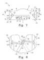
- FIG. 7is a front view of another tibial trial insert of the present disclosure showing a sliding-wedge-type height-adjustment mechanism of the insert for adjusting an overall thickness or height of the insert;
- FIG. 8is a top view of the insert of FIG. 7 with an upper plate of the insert having been removed and showing the adjustment mechanism of the insert in the closed position;
- FIG. 9is a front view of the insert of FIGS. 7 and 8 showing the insert in the opened position
- FIG. 10is a top view of the insert similar to FIG. 8 showing the adjustment mechanism of the insert in the opened position;
- FIG. 11is a front view of yet another tibial trial insert of the present disclosure showing the insert in the closed position
- FIG. 12is a top view of the insert of FIG. 11 with an upper plate of the insert having been removed to reveal a linkage-type height-adjustment mechanism of the insert for adjusting an overall thickness or height of the insert;
- FIG. 13is a front view of the insert of FIGS. 11 and 12 showing the insert in the opened position;
- FIG. 14is a top view of the insert similar to FIG. 12 showing the adjustment mechanism in the fully opened position.
- FIG. 15is a schematic front view of any one of the tibial insert trials disclosed in FIGS. 1-14 showing an alternative rotatable knob actuator of the height-adjustment mechanism.
- An orthopaedic tibial trial insert 10includes an upper plate 12 having an upper articular surface 13 including right and left concave portions 14 and 16 and a lower plate 18 coupled to upper plate 12 and including a lower surface 20 for placement on and engagement with a top surface of an implanted tibial trial tray (not shown), for example. In certain circumstances, the insert 10 may also be placed directly on a surface of the patient's tibia, for example. Insert 10 further includes a height-adjustment mechanism 22 (shown in FIG.
- the height 24 of the insertis measured from the lower surface 20 of the insert 10 to a low point of the upper articular surface 13 .
- the height-adjustment mechanism 22includes drive means or a drive mechanism movable between a closed position and an opened position for adjusting the height of the insert 10 and an actuator coupled to the drive means.
- the actuatoris activated by the surgeon or other technician to move the drive means between the opened and closed positions.
- the drive meansis coupled to the upper plate 12 and the lower plate 18 and the actuator is coupled to the lower plate 18 .
- the actuatormay be coupled to the upper plate 12 as well.
- the insert 10is generally provided for cooperative use with a tibial trial tray (not shown) or a tibial tray implant (not shown).
- Tibial traysoftentimes include a plate and a stem coupled to the plate and received within a pre-drilled hole in the tibia.
- the lower surface 20 of the lower plate 18 of the insert 10is specifically configured to matingly engage and cooperate with an upper surface (not shown) of the tray (not shown). It is the lower surface (not shown) of the plate of the tray, therefore, which is configured to engage and cooperate with a proximal end of the tibia. In some circumstances, however, the lower surface 20 of the lower plate 18 of the insert may be configured to engage and cooperate with the proximal end of the tibia.
- the drive means of the adjustment mechanism 22is a scissors-type drive means which allows the insert 10 to be moved between a closed position, shown in FIGS. 1 , 3 , and 4 , where the upper and lower plates 12 , 18 are generally adjacent to and engaged with each other and an opened position, shown in FIGS. 2 , 5 , and 6 , where the upper and lower plates 12 , 18 are spaced-apart from each other.
- the closed positionthe upper and lower plates 12 , 18 may be engaged with each other as is illustratively shown in FIGS. 1 , 3 , and 4 .
- the upper and lower plates 12 , 18may be spaced-apart from each other in the closed position a distance smaller than the spaced-apart distance of the upper and lower plates 12 , 18 in the opened position.
- the adjustment mechanism 22allows the surgeon and/or other technicians to adjust an overall height 24 of the insert 10 after the insert 10 has been inserted into the knee of a patient.
- the insert 10may remain implanted within the patient while the height 24 of the insert 10 is adjusted.
- the adjustment mechanism 22includes first and second outer crossbars 30 , 32 each having a first end 34 coupled to the lower plate 18 and a second end 36 coupled to the upper plate 12 .
- a pivot pin 38is coupled to the first end 34 each of the first and second outer crossbars 30 , 32 and is secured to two opposite, inner walls 40 of the lower plate 18 which define a cavity 42 of lower plate 18 , as shown in FIG. 2 .
- the cavity 42is formed in an upper surface 26 of the lower plate 18 to receive and stow a portion of the adjustment mechanism 22 when the insert 10 is in the closed position to allow the upper surface 26 of the lower plate 18 and a lower surface 28 of the upper plate 12 to engage each other, as shown in FIG. 1 .
- Another cavityis formed in lower surface 28 of the upper plate 12 to also receive a portion of the adjustment mechanism 22 .
- the adjustment mechanism 22is received within the cavity 42 of the lower plate 18 and the cavity (not shown) of the upper plate 12 when the insert 10 is in the opened position as well.
- a sliding pin 50is coupled to the second end 36 of each of the first and second outer crossbars 30 , 32 , as shown in phantom in FIGS. 3-6 .
- each end of the pin 50is received within a channel 52 formed within each of two opposite, inner walls (not shown) of the upper plate 12 which define the cavity (not shown) formed in the upper plate 12 .
- the sliding pin 50slides within the channels 52 as the adjustment mechanism 22 is moved between the closed and opened positions.
- the adjustment mechanism 22also includes a center crossbar 54 positioned between the first and second outer crossbars 30 , 32 .
- the center crossbar 54similarly includes a first end 56 and a second end 58 .
- the first end 56 of the center crossbar 54is coupled to the upper plate 12 by a pivot pin 60 of the adjustment mechanism 22 , as shown in phantom in FIG. 5 .
- the second end 58 of the center crossbar 54is coupled to the lower plate 18 by sliding pin 62 of the adjustment mechanism 22 , as shown in FIGS. 3-6 .
- each end of the sliding pin 62is received within a channel 64 formed in each of the opposite inner walls 40 defining the cavity 42 formed in the lower plate 18 , as shown in FIG. 2 . Further, the sliding pin 62 slides within the channels 64 as the adjustment mechanism 22 is moved between the closed and opened positions.
- the center crossbar 54further includes a cut-out portion 66 formed at the second end 58 of the center cross bar 54 to provide two arms 68 of the second end 58 which are each attached to the sliding pin 62 .
- a tie-rod 70 of the adjustment mechanism 22is positioned between the arms 68 of the center crossbar 54 , as shown in FIGS. 4 and 6 and is coupled at one end to the sliding pin 62 .
- the other end of the tie-rod 70is coupled to a height-adjustment lever 72 which acts as the user-activated actuator to move the adjustment mechanism 22 between the closed and opened positions.
- the height-adjustment lever 72is positioned within the cavity 42 of the lower plate 18 and is pivotably coupled at one end by a pivot pin 74 to the lower plate 18 .
- a free end of the height-adjustment lever 72is received through a slot 76 formed in a front face 78 of the lower plate 18 , as shown in FIGS. 1-3 and 5 .
- the slot 76is in communication with the cavity 42 of the lower plate 18 .
- the lever 72is coupled to the lower plate 18 at a first pivot point and the tie-rod 70 is pivotably coupled to the lever 72 at a second pivot point spaced-apart from the first pivot point.
- the second pivot point of the second end of the tie-rod 70 and the lever 72is positioned between the first pivot point of the lever 72 and the free end of the lever 72 . Therefore, as the lever 72 is moved counter-clockwise within the slot 76 , the tie-rod 70 is pulled to the right and as the lever 72 is moved clockwise within the slot 76 , the tie-rod 70 is pushed to the left.
- the lever 72is coupled to the lower plate 18 and the slot 76 is formed in the lower plate 18 , it should be appreciated that the lever 72 may be coupled to the upper plate 12 and the slot 76 may be formed in the upper plate 12 to receive the lever 72 therein.
- the height-adjustment lever 72may be moved within the slot 76 of the lower plate 18 by the surgeon or other technician.
- the slot 76is calibrated at two millimeter intervals between ten and twenty millimeters.
- the calibrated scale of the slot 76is calibrated to reflect a combined height of both the height 24 of the insert 10 and a pre-known height or thickness of a tray (not shown) upon which the insert 10 may rest. By knowing the thickness of the tray, therefore, the calibrated scale also visually indicates the height 24 of the insert 10 .
- the insert 10When the height-adjustment lever 72 is aligned with the ten millimeter mark, for example, the insert 10 is in the closed position, as shown in FIGS. 3 and 4 , and the height 24 of the insert 10 plus a height or thickness of a corresponding tray is approximately ten millimeters.
- the illustrative calibrated scale of insert 10is calibrated to reflect a height or thickness of the insert 10 as well as the pre-known height or thickness of the corresponding tray upon which the insert 10 may rest.
- the thickness of a traymay be approximately four millimeters and the scale of the insert 10 is calibrated as such; however, trays having other thickness may be used as well.
- a recalibrated scalemay be used in such circumstances, for example.
- the calibrated scaleis indicative of the height 24 of the insert 10 . Further, it is within the scope of the disclosure for the calibrated scale to refer only to the height of the insert 10 .
- sliding pins 50 and 62are positioned at a left-side of each of their respective channels 52 , 64 when viewing the insert 10 from the front, as shown in phantom in FIG. 3 .
- the tie-rod 70is pulled (because of its point of attachment to the height-adjustment lever 72 at pivot pin 80 ) from the left to the right, as shown in FIG. 4 .
- the tie-bar 70is moved to the right, the sliding pin 62 within the channel 64 of the lower plate 18 is pulled with the tie-bar 70 to the right as well.
- the sliding pin 62is urged to move to the right, the second end 58 of the center crossbar 54 is urged to move to the right as well.
- the first end 56 of the center crossbar 54is therefore urged to pivot about the pivot pin 60 to allow the first end 56 of the center crossbar 54 to move upwardly and raise the upper plate 12 relative to the lower plate 18 , as shown in FIGS. 5 and 6 , to increase the height 24 of the insert 10 .
- the second end 36 of each of the outer crossbars 30 , 32(which is coupled to the upper plate 12 ) is urged to move upwardly with the upper plate 12 as well.
- the sliding pin 50 coupled to the second end 36 of the outer crossbars 30 , 32moves to the right within the channel 52 while the first end 34 of the outer crossbars 30 , 32 pivots about pivot pin 38 to remain coupled to the lower plate 18 .
- This movementpulls the second end 58 of the center crossbar 54 to the right, thus driving the scissors-type drive means of the adjustment mechanism 22 open and raising the upper articular surface 13 of the upper plate 12 .
- adjustment of the insert 10is provided by sliding the lever 72 to the appropriate thickness setting.
- the sliding pin 62is pulled to the right within the channel 64 via its connection through the tie-rod 70 .
- This movementpulls the second end 58 of the center crossbar 54 to the right, thus driving the scissors-type drive means of the adjustment mechanism 22 open to raise the upper articular surface 13 of the upper plate 12 .
- a detent or a plurality of detentsmay be provided within the slot 76 of the lower plate 18 to receive the height-adjustment lever 72 in a locked position.
- a detentmay be formed within the slot 76 at each of the 10, 12, 14, 16, and 20 millimeter thickness settings to receive the lever 72 and secure the insert 10 at the desired height.
- FIGS. 7-10another tibial trial insert 110 is provided which is also adjustable between a closed position, shown in FIGS. 7 and 8 , and an opened position, shown in FIGS. 9 and 10 , in order to adjust the overall height or thickness 24 of the insert 110 .
- Portions of insert 110are the same as or similar to portions of insert 10 ; as such, like reference numerals have been used to correspond to like components.
- the insert 110includes an alternative upper plate 112 having an upper articular surface 13 including concave portions 14 , 16 and an alternative lower plate 118 .
- An adjustment mechanism 122 of the insert 110is positioned between and coupled to both the upper and lower plates 112 , 118 .
- the adjustment mechanism 122 shown in FIGS. 7-10includes a sliding-wedge drive means and an actuator, or lever 172 , to move the drive means between the opened and closed positions.
- the drive means of the adjustment mechanism 122includes two sliding wedges 130 , 132 .
- Each sliding wedge 130 , 132includes an angled top surface 134 and an angled bottom surface 136 .
- the angled top surface 134 of each of the sliding wedges 130 , 132matingly engages and cooperates with respective outer or lower angled surfaces 138 of the upper plate 112 .
- the angled bottom surface 136 of each of the sliding wedges 130 , 132matingly engages and cooperates with respective outer or upper angled surfaces 140 of the lower plate 118 , as shown in FIGS. 7 and 9 .
- each of the sliding wedges 130 , 132are slidable relative to the upper and lower plates 112 , 118 along angled surfaces 138 and 140 of the upper and lower plates 112 , 118 .
- the adjustment mechanism 122 of the insert 110further includes a first tie-rod 142 coupled to the first sliding wedge 130 and a second tie-rod 144 coupled to the second sliding wedge 132 .
- each tie-rod 142 , 144includes a first end pivotably coupled to the respective wedge 130 , 132 by a pin 146 and a second end coupled to a height-adjustment lever 172 of the adjustment mechanism 122 .
- the height-adjustment lever 172is pivotably coupled to the bottom plate 118 by the pivot pin 74 .
- the lower plate 118includes a cavity (not shown) formed therein and the adjustment lever is coupled to a bottom wall of the cavity.
- the first tie-rod 142is pivotably coupled to the lever 172 by a pivot pin 150 at a pivot point spaced-apart from and behind the pivot point of the lever 172 .
- the second tie-rod 144is pivotably coupled to the lever 172 by a pivot pin 152 at a pivot point spaced-apart from and in front of the pivot point of the lever 172 . Therefore, as the lever 172 is pivoted about the pivot point 74 in a counter-clockwise direction, as shown in FIG. 8 , the first tie-rod 142 is pulled to the left or toward the center of the insert 110 while the second tie-rod 144 is pulled to the right or toward the center of the insert 110 .
- each of the respective tie-rods 142 , 144are pulled toward the center of the insert 110 , the respective first and second sliding wedges 130 , 132 to which each tie-rod 142 , 144 is attached are also pulled toward the center of the insert 110 .
- each sliding wedge 130 , 132acts against the respective angled surfaces 138 , 140 of the upper and lower plates 112 , 118 to force the upper and lower plates 112 , 118 to move away from each other as the sliding wedges 130 , 132 are pulled inwardly toward the center of the insert 110 .
- the tie-rods 142 , 144 and the respective sliding wedges 130 , 132are moved away from each other or away from the center of the insert 110 to reduce the distance between the upper and lower plates 112 , 118 and thus reduce the overall height 24 of the insert 110 .
- the lower plate 118includes a slot 76 for receiving the height-adjustment lever 172 .
- the slot 76is also calibrated at two millimeter intervals between ten and twenty millimeters. The calibrations provide a visual indication of the overall height 24 of the insert 110 .
- the slot 76may include detents (not shown) at each calibrated interval (i.e., at 10 millimeters, at 12 millimeters, at 14 millimeters, etc.) to receive the height-adjustment lever 172 and lock the height-adjustment lever 172 at that location and maintain the insert 110 at the desired thickness or height 24 .
- the insert 110is in the closed position such that the upper and lower plates 112 , 118 are adjacent each other and the combined thickness 24 of the insert 110 and the tray (not shown) upon which the insert 110 may rest is illustratively 10 millimeters as shown by the height-adjustment lever 172 .
- the insert 110is in the opened position such that the upper and lower plates 112 , 118 are spaced-apart from each other and the thickness 24 of the insert 110 is set to the largest setting.
- the height-adjustment lever 172is positioned at the twenty millimeter mark to represent an overall height including the height 24 of the insert 110 and the height of a tray (not shown) of twenty millimeters.
- each of the sliding wedges 130 , 132may be coupled to the upper and lower plates 112 , 118 via a tongue-and-groove connection (not shown), for example, between the angled surfaces 134 , 136 of the wedges 130 , 132 and the angled surfaces 138 , 140 of the respective upper and lower plates 112 , 118 .
- the adjustment mechanism 122may also include a leaf spring 156 to provide a compressive force between the upper plate 112 and the lower plate 118 , as shown in phantom in FIG. 9 .
- the wedges 130 , 132are coupled to the lower plate 118 (although the wedges 130 , 132 may also be coupled to the upper plate 112 ). Therefore, the spring 156 provides a compressive force between the upper plate 112 and the lower plate 118 to couple the upper and lower plates 112 , 118 together. As such, the spring 156 operates the couple the sliding wedges 130 , 132 to both the upper and the lower plates 112 , 118 .
- the lower plate 118includes two pins or posts 158 spaced-apart from each other and the upper plate 112 includes a single pin or post 154 positioned generally between the posts 158 of the lower plate 118 .
- the leaf spring 156is threaded under the posts 158 of the lower plate 118 and over the post 154 of the upper plate 112 to urge the upper and lower plates 112 , 118 toward each other.
- the leaf spring 156 or another suitable springmay be provided for the insert 10 shown in FIGS. 1-6 as well to provide a compressive force between the upper and lower plates 12 , 18 .
- the adjustment mechanism 122therefore, acts against the compressive force of the leaf spring 156 when the surgeon or other technician is increasing the thickness 24 of the insert 110 , but works with the leaf spring 156 when decreasing the thickness 24 of the insert 110 .
- tibial trial insert 210Similar to insert 10 , tibial trial insert 210 includes the upper plate 12 and the lower plate 18 . Each of the upper and lower plates 12 , 18 include cavities (not shown) formed therein to house an adjustment mechanism 222 of the insert 210 for adjusting an overall height of the insert 210 .
- the adjustment mechanism 222illustratively includes a linkage-style drive means and an actuator to operate the drive means.
- the adjustment mechanism 222includes the height-adjustment lever 172 pivotably coupled to the lower plate 12 by the pivot pin 74 , first and second tie-rods 142 , 144 coupled to the lever 172 , and a first and second linkage 230 , 232 coupled to one of the respective tie-rods 142 , 144 . As shown in FIGS. 12-14 , the adjustment mechanism 222 includes the height-adjustment lever 172 pivotably coupled to the lower plate 12 by the pivot pin 74 , first and second tie-rods 142 , 144 coupled to the lever 172 , and a first and second linkage 230 , 232 coupled to one of the respective tie-rods 142 , 144 . As shown in FIGS.
- the first tie-rod 142is coupled at its second end by the pivot pin 152 at a pivot point on the lever 172 spaced-apart from and in front of the pivot point 74 of the lever 172 and the second tie-rod 144 is coupled at its second end by the pivot pin 150 at a pivot point on the lever 172 spaced-apart from and behind the pivot point of the lever 172 as viewed from above.
- the attachment point of the tie-rods 142 , 144 to the lever 172 of the adjustment mechanism 222differs from the attachment point of the tie-rods 142 , 144 to the lever 172 of the sliding-wedge adjustment mechanism 122 of the insert 110 .
- each tie-rod 142 , 144is pivotably coupled to one of the respective linkages 230 , 232 .
- Each linkage 230 , 232includes a first link 234 pivotably coupled to the lower plate 18 and a second link 236 pivotably coupled to the upper plate 12 .
- the first and second links 234 , 236 of each linkage 230 , 232are also pivotably coupled to each other by a central pin 240 .
- Each tie-rod 142 , 144is also coupled to the central pin 240 of each respective linkage 230 , 232 .
- each linkage 230 , 232is moved from a collapsed position toward an expanded position, as shown in FIG. 13 , to move the upper plate 12 and the lower plate 18 away from each other, thus increasing the overall thickness 24 of the insert 210 .
- the lower plate 18 of the insert 210may include detents (not shown) formed in the slot 76 of the lower plate 18 which correspond to a particular height or thickness 24 of the insert 210 to receive the lever 172 therein and secure the insert 210 at that particular desired height.
- each of adjustment mechanisms 22 , 122 , 222 described aboveis the lever 72 , 172
- other actuatorsmay be used.
- an alternative actuatorsuch as a knob 372 is shown in FIG. 15 .
- the knob 372may be used to replace the levers 72 , 172 of the adjustment mechanisms 22 , 122 , 222 described above, for example, to drive the various scissors-type, wedge, and linkage mechanisms of each adjustment mechanism.
- the knob 372is mounted to a shaft (not shown) which may extend through the upper or lower plates of the insert.
- the shaftis then coupled to a vertical bar 274 , as shown in FIG. 15 , and the second ends of each tie-rod 142 , 144 of the adjustment mechanisms 122 , 222 or the second end of the tie-rod 70 of the adjustment mechanism 22 are then coupled to one end of the vertical bar 274 .
- Rotation of the knob 372causes the tie-rods 70 , 142 , 144 to pull in or push out depending on the direction of rotation and whether the tie-rods 70 , 142 , 144 are coupled to the vertical bar 274 above or below its pivot point.
- first tie-rod 142is coupled to the bottom of the vertical bar 274 below the pivot point of the vertical bar 274 and the second tie-rod 144 is coupled to the top of the vertical bar 274 above the pivot point of the vertical bar 274
- clockwise rotation of the knob 372pulls the tie-rods 142 , 144 toward the center of the insert and counterclockwise rotation of the knob pushes the tie-rods 142 , 144 away from the center of the insert.
- the connection between the tie-rods 142 , 144 and the vertical bar 274may also be switched such that clockwise rotation of the knob 372 pushes the tie-rods 142 , 144 away from each other.
- the orientation of the tie-rods 142 , 144 with respect to the vertical bar 274may be configured for use with either the sliding wedges 130 , 132 and/or the linkages 230 , 232 .
- the knob actuator 372may also be used with the scissors-type drive means of the adjustment mechanism 22 shown in FIGS. 1-6 .
- the tie-rod 70may be coupled to the vertical bar 274 at a point spaced away from the pivot point of the vertical bar 274 such that rotation of the knob causes the tie-rod 70 to move generally laterally and thus move the center crossbar 54 .
- the knob 372may also be calibrated to indicate a particular overall height of the trial.
Landscapes
- Health & Medical Sciences (AREA)
- Life Sciences & Earth Sciences (AREA)
- Orthopedic Medicine & Surgery (AREA)
- Transplantation (AREA)
- Oral & Maxillofacial Surgery (AREA)
- General Health & Medical Sciences (AREA)
- Engineering & Computer Science (AREA)
- Biomedical Technology (AREA)
- Heart & Thoracic Surgery (AREA)
- Veterinary Medicine (AREA)
- Public Health (AREA)
- Animal Behavior & Ethology (AREA)
- Surgery (AREA)
- Physical Education & Sports Medicine (AREA)
- Vascular Medicine (AREA)
- Cardiology (AREA)
- Nuclear Medicine, Radiotherapy & Molecular Imaging (AREA)
- Biophysics (AREA)
- Pathology (AREA)
- Medical Informatics (AREA)
- Molecular Biology (AREA)
- Prostheses (AREA)
Abstract
Description
Claims (3)
Priority Applications (2)
| Application Number | Priority Date | Filing Date | Title |
|---|---|---|---|
| US12/619,980US8435304B2 (en) | 2004-11-24 | 2009-11-17 | Adjustable knee tibial trial insert |
| US13/835,904US9277965B2 (en) | 2004-11-24 | 2013-03-15 | Adjustable knee tibial trial insert |
Applications Claiming Priority (3)
| Application Number | Priority Date | Filing Date | Title |
|---|---|---|---|
| US10/997,493US7309363B2 (en) | 2004-11-24 | 2004-11-24 | Adjustable knee tibial trial insert |
| US11/935,827US7632314B2 (en) | 2004-11-24 | 2007-11-06 | Adjustable knee tibial trial insert |
| US12/619,980US8435304B2 (en) | 2004-11-24 | 2009-11-17 | Adjustable knee tibial trial insert |
Related Parent Applications (1)
| Application Number | Title | Priority Date | Filing Date |
|---|---|---|---|
| US11/935,827DivisionUS7632314B2 (en) | 2004-11-24 | 2007-11-06 | Adjustable knee tibial trial insert |
Related Child Applications (1)
| Application Number | Title | Priority Date | Filing Date |
|---|---|---|---|
| US13/835,904ContinuationUS9277965B2 (en) | 2004-11-24 | 2013-03-15 | Adjustable knee tibial trial insert |
Publications (2)
| Publication Number | Publication Date |
|---|---|
| US20100063595A1 US20100063595A1 (en) | 2010-03-11 |
| US8435304B2true US8435304B2 (en) | 2013-05-07 |
Family
ID=36461930
Family Applications (4)
| Application Number | Title | Priority Date | Filing Date |
|---|---|---|---|
| US10/997,493Active2025-12-13US7309363B2 (en) | 2004-11-24 | 2004-11-24 | Adjustable knee tibial trial insert |
| US11/935,827Expired - LifetimeUS7632314B2 (en) | 2004-11-24 | 2007-11-06 | Adjustable knee tibial trial insert |
| US12/619,980Active2026-02-03US8435304B2 (en) | 2004-11-24 | 2009-11-17 | Adjustable knee tibial trial insert |
| US13/835,904Expired - LifetimeUS9277965B2 (en) | 2004-11-24 | 2013-03-15 | Adjustable knee tibial trial insert |
Family Applications Before (2)
| Application Number | Title | Priority Date | Filing Date |
|---|---|---|---|
| US10/997,493Active2025-12-13US7309363B2 (en) | 2004-11-24 | 2004-11-24 | Adjustable knee tibial trial insert |
| US11/935,827Expired - LifetimeUS7632314B2 (en) | 2004-11-24 | 2007-11-06 | Adjustable knee tibial trial insert |
Family Applications After (1)
| Application Number | Title | Priority Date | Filing Date |
|---|---|---|---|
| US13/835,904Expired - LifetimeUS9277965B2 (en) | 2004-11-24 | 2013-03-15 | Adjustable knee tibial trial insert |
Country Status (1)
| Country | Link |
|---|---|
| US (4) | US7309363B2 (en) |
Cited By (6)
| Publication number | Priority date | Publication date | Assignee | Title |
|---|---|---|---|---|
| US20130103160A1 (en)* | 2010-04-22 | 2013-04-25 | Depuy (Ireland) | Composite trial prosthesis |
| US8968412B2 (en) | 2011-06-30 | 2015-03-03 | Depuy (Ireland) | Trialing system for a knee prosthesis and method of use |
| US9277965B2 (en) | 2004-11-24 | 2016-03-08 | DePuy Synthes Products, Inc. | Adjustable knee tibial trial insert |
| US9861491B2 (en) | 2014-04-30 | 2018-01-09 | Depuy Ireland Unlimited Company | Tibial trial system for a knee prosthesis |
| US10195056B2 (en) | 2015-10-19 | 2019-02-05 | Depuy Ireland Unlimited Company | Method for preparing a patient's tibia to receive an implant |
| US10537445B2 (en) | 2015-10-19 | 2020-01-21 | Depuy Ireland Unlimited Company | Surgical instruments for preparing a patient's tibia to receive an implant |
Families Citing this family (78)
| Publication number | Priority date | Publication date | Assignee | Title |
|---|---|---|---|---|
| US7217291B2 (en)* | 2003-12-08 | 2007-05-15 | St. Francis Medical Technologies, Inc. | System and method for replacing degenerated spinal disks |
| US8303597B2 (en) | 2005-02-08 | 2012-11-06 | Rasmussen G Lynn | Systems and methods for guiding cuts to a femur and tibia during a knee arthroplasty |
| US8317797B2 (en) | 2005-02-08 | 2012-11-27 | Rasmussen G Lynn | Arthroplasty systems and methods for optimally aligning and tensioning a knee prosthesis |
| US20060184176A1 (en)* | 2005-02-17 | 2006-08-17 | Zimmer Technology, Inc. | Tibial trialing assembly and method of trialing a tibial implant |
| DE102005049851A1 (en)* | 2005-10-18 | 2007-04-26 | Plus Orthopedics Ag | StrapsTie device |
| US8231631B2 (en)* | 2006-03-20 | 2012-07-31 | Perception Raisonnement Action En Medecine | Distractor system |
| US8070823B2 (en) | 2006-11-07 | 2011-12-06 | Biomedflex Llc | Prosthetic ball-and-socket joint |
| US9005307B2 (en) | 2006-11-07 | 2015-04-14 | Biomedflex, Llc | Prosthetic ball-and-socket joint |
| US20110166671A1 (en) | 2006-11-07 | 2011-07-07 | Kellar Franz W | Prosthetic joint |
| WO2008058205A1 (en) | 2006-11-07 | 2008-05-15 | Biomedflex, Llc | Medical implants |
| US8512413B2 (en) | 2006-11-07 | 2013-08-20 | Biomedflex, Llc | Prosthetic knee joint |
| US8308812B2 (en) | 2006-11-07 | 2012-11-13 | Biomedflex, Llc | Prosthetic joint assembly and joint member therefor |
| US8029574B2 (en) | 2006-11-07 | 2011-10-04 | Biomedflex Llc | Prosthetic knee joint |
| DE102007032150B4 (en)* | 2007-07-04 | 2013-10-31 | Aesculap Ag | Artificial meniscus part and knee joint prosthesis |
| US8128703B2 (en) | 2007-09-28 | 2012-03-06 | Depuy Products, Inc. | Fixed-bearing knee prosthesis having interchangeable components |
| US8632600B2 (en) | 2007-09-25 | 2014-01-21 | Depuy (Ireland) | Prosthesis with modular extensions |
| US9204967B2 (en) | 2007-09-28 | 2015-12-08 | Depuy (Ireland) | Fixed-bearing knee prosthesis having interchangeable components |
| CN101977570B (en)* | 2008-02-11 | 2013-08-14 | 精密技术公司 | Knee prosthesis system with slope |
| US8377073B2 (en) | 2008-04-21 | 2013-02-19 | Ray Wasielewski | Method of designing orthopedic implants using in vivo data |
| US8197489B2 (en)* | 2008-06-27 | 2012-06-12 | Depuy Products, Inc. | Knee ligament balancer |
| US8337498B2 (en) | 2008-08-13 | 2012-12-25 | Rasmussen G Lynn | Systems and methods for providing a bone milling device |
| EP2158879A1 (en)* | 2008-09-01 | 2010-03-03 | MMK Consulting GmbH | Trial Prosthesis for total knee arthroplasty |
| US8784490B2 (en) | 2008-11-18 | 2014-07-22 | Ray C. Wasielewski | Method of designing orthopedic implants using in vivo data |
| US20100250276A1 (en)* | 2009-03-26 | 2010-09-30 | Jay Pierce | System and method for an orthopedic dynamic data repository and registry for clinical |
| US9011547B2 (en) | 2010-01-21 | 2015-04-21 | Depuy (Ireland) | Knee prosthesis system |
| ES2632995T3 (en) | 2010-07-24 | 2017-09-18 | Zimmer, Inc. | Asymmetric tibia components for a knee prosthesis |
| US8764840B2 (en) | 2010-07-24 | 2014-07-01 | Zimmer, Inc. | Tibial prosthesis |
| WO2012020460A1 (en)* | 2010-08-13 | 2012-02-16 | Johnson & Johnson Kabushiki Kaisha | Real time knee balancer |
| US8591594B2 (en) | 2010-09-10 | 2013-11-26 | Zimmer, Inc. | Motion facilitating tibial components for a knee prosthesis |
| US8317870B2 (en) | 2010-09-30 | 2012-11-27 | Depuy Products, Inc. | Tibial component of a knee prosthesis having an angled cement pocket |
| US8287601B2 (en) | 2010-09-30 | 2012-10-16 | Depuy Products, Inc. | Femoral component of a knee prosthesis having an angled cement pocket |
| US8603101B2 (en)* | 2010-12-17 | 2013-12-10 | Zimmer, Inc. | Provisional tibial prosthesis system |
| US9597090B2 (en) | 2010-12-17 | 2017-03-21 | Zimmer, Inc. | Cut guide attachment for use in tibial prosthesis systems |
| US8591593B2 (en) | 2011-04-15 | 2013-11-26 | Biomet Manufacturing, Llc | Pivoting tibial tray |
| GB201114059D0 (en) | 2011-08-16 | 2011-09-28 | Depuy Ireland | Attachment mechanism |
| GB201115411D0 (en)* | 2011-09-07 | 2011-10-19 | Depuy Ireland | Surgical instrument |
| EP3175824B1 (en) | 2011-11-18 | 2019-01-02 | Zimmer, Inc. | Tibial bearing component for a knee prosthesis with improved articular characteristics |
| ES2585838T3 (en) | 2011-11-21 | 2016-10-10 | Zimmer, Inc. | Tibial base plate with asymmetric placement of fixing structures |
| US10258477B2 (en) | 2011-12-07 | 2019-04-16 | Smith & Nephew, Inc. | Tibial insert with resistance-actuated post |
| EP3492044A1 (en) | 2011-12-07 | 2019-06-05 | Smith & Nephew, Inc | Posterior stabilized insert trial with adjustable post |
| IN2014DN07145A (en) | 2012-01-30 | 2015-04-24 | Zimmer Inc | |
| US9216086B2 (en)* | 2012-02-01 | 2015-12-22 | Zimmer, Inc. | Adjustable provisional component of a medical device |
| US20130261759A1 (en) | 2012-03-30 | 2013-10-03 | Zimmer, Inc. | Tibial prosthesis systems, kits, and methods |
| US10206792B2 (en) | 2012-03-31 | 2019-02-19 | Depuy Ireland Unlimited Company | Orthopaedic surgical system for determining joint forces of a patients knee joint |
| US10130480B2 (en) | 2013-03-13 | 2018-11-20 | Howmedica Osteonics Corp. | Modular patella trials |
| US9408557B2 (en)* | 2013-03-18 | 2016-08-09 | Orthosensor Inc. | System and method to change a contact point of the muscular-skeletal system |
| FR3008301B1 (en)* | 2013-07-11 | 2016-12-23 | Biotechni | DEVICE FOR DISTRACTING A FABRIC |
| DE102013213831B4 (en)* | 2013-07-15 | 2015-01-29 | Heraeus Medical Gmbh | Knee spacer for temporary replacement of an artificial knee joint |
| US9925052B2 (en) | 2013-08-30 | 2018-03-27 | Zimmer, Inc. | Method for optimizing implant designs |
| US9592133B2 (en) | 2013-09-23 | 2017-03-14 | Zimmer, Inc. | Spacer block |
| CN103598934B (en)* | 2013-10-30 | 2015-12-30 | 嘉思特华剑医疗器材(天津)有限公司 | A kind of knee-joint prosthesis fill-in pad |
| JP6521671B2 (en)* | 2014-02-27 | 2019-05-29 | 京セラ株式会社 | Total knee arthroplasty tibial trial |
| TWM479734U (en)* | 2014-02-27 | 2014-06-11 | United Orthopedic Corp | Stack-up assembly for tibial insert trial |
| US20180206649A1 (en)* | 2015-03-27 | 2018-07-26 | Skip Hop, Inc. | Baby Bouncer with Adjustable Height Mechanism |
| CN104799981B (en)* | 2015-05-22 | 2016-10-05 | 北京爱康宜诚医疗器材股份有限公司 | Joint prosthesis platform gasket assembly |
| US20170065438A1 (en)* | 2015-09-08 | 2017-03-09 | Brian G. Burnikel | Adjustable tibial trial |
| WO2017053196A1 (en) | 2015-09-21 | 2017-03-30 | Zimmer, Inc. | Prosthesis system including tibial bearing component |
| WO2017185108A2 (en)* | 2016-04-28 | 2017-11-02 | Medfit Beratungs-Und Beteiligunges.M.B.H | Dynamic ligament balancing system (dlb) |
| US10470900B2 (en)* | 2016-06-17 | 2019-11-12 | Paragon 28, Inc. | Implants, devices, systems, kits and methods of implanting |
| JP2020500600A (en) | 2016-11-30 | 2020-01-16 | ジー リン ラスムッセン | System and method for providing a tibial baseplate |
| US12414862B2 (en) | 2016-11-30 | 2025-09-16 | G. Lynn Rasmussen | Systems and methods for providing a tibial baseplate system |
| CN106726023B (en)* | 2016-12-30 | 2019-09-20 | 北京爱康宜诚医疗器材有限公司 | Joint Position Calibration Device |
| EP3592298B1 (en)* | 2017-03-07 | 2023-12-13 | DSB Co Pty Ltd | Surgical spacer device with sensor |
| US10675153B2 (en) | 2017-03-10 | 2020-06-09 | Zimmer, Inc. | Tibial prosthesis with tibial bearing component securing feature |
| WO2018208612A1 (en) | 2017-05-12 | 2018-11-15 | Zimmer, Inc. | Femoral prostheses with upsizing and downsizing capabilities |
| CN107595357A (en)* | 2017-09-29 | 2018-01-19 | 北京爱康宜诚医疗器材有限公司 | Osteotomy adjustable shim |
| CN107647948A (en)* | 2017-09-29 | 2018-02-02 | 北京爱康宜诚医疗器材有限公司 | Ankle joint fusion device |
| US11426282B2 (en) | 2017-11-16 | 2022-08-30 | Zimmer, Inc. | Implants for adding joint inclination to a knee arthroplasty |
| US11678894B2 (en) | 2017-12-15 | 2023-06-20 | Jonathan P. Cabot | Knee balancing instrument |
| EP3773277A4 (en)* | 2018-04-11 | 2021-12-29 | Vivek Mohan | A haptic based system for bone gap measurement and distraction |
| US10835380B2 (en) | 2018-04-30 | 2020-11-17 | Zimmer, Inc. | Posterior stabilized prosthesis system |
| WO2021048202A1 (en) | 2019-09-10 | 2021-03-18 | Depuy Ireland Unlimited Company | Adjustable tibial trial instrument and orthopaedic surgical method of using the same |
| DE102020208501A1 (en) | 2020-07-07 | 2022-01-13 | Aesculap Ag | Tibial trial implant |
| EP4011334B1 (en) | 2020-12-09 | 2025-10-01 | Aesculap AG | Adjustable tibial trial insert |
| US11612421B1 (en)* | 2021-09-20 | 2023-03-28 | Little Engine, LLC | Tensioner-balancer for knee joint |
| US20230329876A1 (en)* | 2022-04-15 | 2023-10-19 | Exactech, Inc. | Mechanical ligament balancing devices, kits, and methods |
| CN115919515B (en)* | 2023-03-14 | 2023-05-26 | 中国人民解放军总医院第一医学中心 | Intervertebral prosthesis |
| WO2024206534A1 (en)* | 2023-03-27 | 2024-10-03 | Assini Joseph B | Devices for setting thickness during total knee arthroplasty |
Citations (22)
| Publication number | Priority date | Publication date | Assignee | Title |
|---|---|---|---|---|
| US5522899A (en) | 1988-06-28 | 1996-06-04 | Sofamor Danek Properties, Inc. | Artificial spinal fusion implants |
| US5569263A (en) | 1995-01-12 | 1996-10-29 | Orthopaedic Innovations, Inc. | Adjustable provisional articulating device |
| WO1997009939A1 (en) | 1995-09-15 | 1997-03-20 | Midwest Orthopedic Research Foundation | Arthroplasty trial prosthesis, alignment devices and associated methods |
| US5702464A (en) | 1996-02-20 | 1997-12-30 | Smith & Nephew Inc. | Modular trial tibial insert |
| US5782832A (en) | 1996-10-01 | 1998-07-21 | Surgical Dynamics, Inc. | Spinal fusion implant and method of insertion thereof |
| US6206928B1 (en) | 1999-04-29 | 2001-03-27 | Depuy Orthpaedics, Inc. | Orthopaedic tray trial |
| US6258126B1 (en) | 1997-09-09 | 2001-07-10 | Depuy Orthopaedics, Inc. | Cushioned joint prosthesis |
| US20020128716A1 (en) | 1999-07-26 | 2002-09-12 | Howard Cohen | Spinal surgical prosthesis |
| US6641614B1 (en) | 1997-05-01 | 2003-11-04 | Spinal Concepts, Inc. | Multi-variable-height fusion device |
| US6692495B1 (en)* | 1999-10-14 | 2004-02-17 | Fred Zacouto | Vertebral fixator and articulation |
| US6875235B2 (en) | 1999-10-08 | 2005-04-05 | Bret A. Ferree | Prosthetic joints with contained compressible resilient members |
| US6893464B2 (en)* | 2002-03-05 | 2005-05-17 | The Regents Of The University Of California | Method and apparatus for providing an expandable spinal fusion cage |
| US20050234555A1 (en)* | 2004-04-16 | 2005-10-20 | Depuy Spine, Inc. | Intervertebral disc with monitoring and adjusting capabilities |
| US20050261683A1 (en)* | 2001-07-02 | 2005-11-24 | Veldhuizen Albert G | Collapsible and expandable instrument for insertion in a dorsal vertebra |
| US20060069436A1 (en) | 2004-09-30 | 2006-03-30 | Depuy Spine, Inc. | Trial disk implant |
| US20060069447A1 (en) | 2004-09-30 | 2006-03-30 | Disilvestro Mark R | Adjustable, remote-controllable orthopaedic prosthesis and associated method |
| US20060149277A1 (en)* | 2003-02-27 | 2006-07-06 | Philippe Cinquin | Knee distractor |
| US7083650B2 (en) | 2004-05-13 | 2006-08-01 | Moskowitz Nathan C | Artificial expansile total lumbar and thoracic discs for posterior placement without supplemental instrumentation and its adaptation for anterior placement of artificial cervical, thoracic and lumbar discs |
| US7087055B2 (en)* | 2002-06-25 | 2006-08-08 | Sdgi Holdings, Inc. | Minimally invasive expanding spacer and method |
| US7217291B2 (en) | 2003-12-08 | 2007-05-15 | St. Francis Medical Technologies, Inc. | System and method for replacing degenerated spinal disks |
| US20100249933A1 (en)* | 2002-11-21 | 2010-09-30 | Warsaw Orthopedic, Inc. | Systems and techniques for intravertebral spinal stabilization with expandable devices |
| US20110307066A1 (en)* | 2004-02-13 | 2011-12-15 | Warsaw Orthopedic, Inc. | Spacer with Height and Angle Adjustments for Spacing Vertebral Members |
Family Cites Families (2)
| Publication number | Priority date | Publication date | Assignee | Title |
|---|---|---|---|---|
| DE19850100A1 (en)* | 1998-10-29 | 2000-05-04 | Henkel Kgaa | Polymer granules through fluidized bed granulation |
| US7309363B2 (en) | 2004-11-24 | 2007-12-18 | Depuy Products, Inc. | Adjustable knee tibial trial insert |
- 2004
- 2004-11-24USUS10/997,493patent/US7309363B2/enactiveActive
- 2007
- 2007-11-06USUS11/935,827patent/US7632314B2/ennot_activeExpired - Lifetime
- 2009
- 2009-11-17USUS12/619,980patent/US8435304B2/enactiveActive
- 2013
- 2013-03-15USUS13/835,904patent/US9277965B2/ennot_activeExpired - Lifetime
Patent Citations (23)
| Publication number | Priority date | Publication date | Assignee | Title |
|---|---|---|---|---|
| US5522899A (en) | 1988-06-28 | 1996-06-04 | Sofamor Danek Properties, Inc. | Artificial spinal fusion implants |
| US5569263A (en) | 1995-01-12 | 1996-10-29 | Orthopaedic Innovations, Inc. | Adjustable provisional articulating device |
| WO1997009939A1 (en) | 1995-09-15 | 1997-03-20 | Midwest Orthopedic Research Foundation | Arthroplasty trial prosthesis, alignment devices and associated methods |
| US5733292A (en) | 1995-09-15 | 1998-03-31 | Midwest Orthopaedic Research Foundation | Arthroplasty trial prosthesis alignment devices and associated methods |
| US5702464A (en) | 1996-02-20 | 1997-12-30 | Smith & Nephew Inc. | Modular trial tibial insert |
| US5782832A (en) | 1996-10-01 | 1998-07-21 | Surgical Dynamics, Inc. | Spinal fusion implant and method of insertion thereof |
| US6641614B1 (en) | 1997-05-01 | 2003-11-04 | Spinal Concepts, Inc. | Multi-variable-height fusion device |
| US6258126B1 (en) | 1997-09-09 | 2001-07-10 | Depuy Orthopaedics, Inc. | Cushioned joint prosthesis |
| US6206928B1 (en) | 1999-04-29 | 2001-03-27 | Depuy Orthpaedics, Inc. | Orthopaedic tray trial |
| US20020128716A1 (en) | 1999-07-26 | 2002-09-12 | Howard Cohen | Spinal surgical prosthesis |
| US6875235B2 (en) | 1999-10-08 | 2005-04-05 | Bret A. Ferree | Prosthetic joints with contained compressible resilient members |
| US6692495B1 (en)* | 1999-10-14 | 2004-02-17 | Fred Zacouto | Vertebral fixator and articulation |
| US20050261683A1 (en)* | 2001-07-02 | 2005-11-24 | Veldhuizen Albert G | Collapsible and expandable instrument for insertion in a dorsal vertebra |
| US6893464B2 (en)* | 2002-03-05 | 2005-05-17 | The Regents Of The University Of California | Method and apparatus for providing an expandable spinal fusion cage |
| US7087055B2 (en)* | 2002-06-25 | 2006-08-08 | Sdgi Holdings, Inc. | Minimally invasive expanding spacer and method |
| US20100249933A1 (en)* | 2002-11-21 | 2010-09-30 | Warsaw Orthopedic, Inc. | Systems and techniques for intravertebral spinal stabilization with expandable devices |
| US20060149277A1 (en)* | 2003-02-27 | 2006-07-06 | Philippe Cinquin | Knee distractor |
| US7217291B2 (en) | 2003-12-08 | 2007-05-15 | St. Francis Medical Technologies, Inc. | System and method for replacing degenerated spinal disks |
| US20110307066A1 (en)* | 2004-02-13 | 2011-12-15 | Warsaw Orthopedic, Inc. | Spacer with Height and Angle Adjustments for Spacing Vertebral Members |
| US20050234555A1 (en)* | 2004-04-16 | 2005-10-20 | Depuy Spine, Inc. | Intervertebral disc with monitoring and adjusting capabilities |
| US7083650B2 (en) | 2004-05-13 | 2006-08-01 | Moskowitz Nathan C | Artificial expansile total lumbar and thoracic discs for posterior placement without supplemental instrumentation and its adaptation for anterior placement of artificial cervical, thoracic and lumbar discs |
| US20060069436A1 (en) | 2004-09-30 | 2006-03-30 | Depuy Spine, Inc. | Trial disk implant |
| US20060069447A1 (en) | 2004-09-30 | 2006-03-30 | Disilvestro Mark R | Adjustable, remote-controllable orthopaedic prosthesis and associated method |
Non-Patent Citations (1)
| Title |
|---|
| Graichen, F. et al., "Inductively Powered Telemetry System for in Vivo Measurement with Orthopaedic Implants," Biotelemetry XIII, Mar. 26-31, 1995, Williamsburg, VA, pp. 75-80. |
Cited By (12)
| Publication number | Priority date | Publication date | Assignee | Title |
|---|---|---|---|---|
| US9277965B2 (en) | 2004-11-24 | 2016-03-08 | DePuy Synthes Products, Inc. | Adjustable knee tibial trial insert |
| US20130103160A1 (en)* | 2010-04-22 | 2013-04-25 | Depuy (Ireland) | Composite trial prosthesis |
| US8945231B2 (en)* | 2010-04-22 | 2015-02-03 | Depuy (Ireland) | Composite trial prosthesis |
| US8968412B2 (en) | 2011-06-30 | 2015-03-03 | Depuy (Ireland) | Trialing system for a knee prosthesis and method of use |
| US9861491B2 (en) | 2014-04-30 | 2018-01-09 | Depuy Ireland Unlimited Company | Tibial trial system for a knee prosthesis |
| US10265183B2 (en) | 2014-04-30 | 2019-04-23 | Depuy Ireland Unlimited Company | Tibial trial system for a knee prosthesis and method |
| US10952863B2 (en) | 2014-04-30 | 2021-03-23 | Depuy Ireland Unlimited Company | Tibial trial system for a knee prosthesis and method |
| US11684479B2 (en) | 2014-04-30 | 2023-06-27 | Depuy Ireland Unlimited Company | Tibial trial system for a knee prosthesis and method |
| US10195056B2 (en) | 2015-10-19 | 2019-02-05 | Depuy Ireland Unlimited Company | Method for preparing a patient's tibia to receive an implant |
| US10537445B2 (en) | 2015-10-19 | 2020-01-21 | Depuy Ireland Unlimited Company | Surgical instruments for preparing a patient's tibia to receive an implant |
| US10952874B2 (en) | 2015-10-19 | 2021-03-23 | Depuy Ireland Unlimited Company | Method for preparing a patient's tibia to receive an implant |
| US11806252B2 (en) | 2015-10-19 | 2023-11-07 | Depuy Ireland Unlimited Company | Surgical instruments for preparing a patient's tibia to receive an implant |
Also Published As
| Publication number | Publication date |
|---|---|
| US20080058946A1 (en) | 2008-03-06 |
| US20060111790A1 (en) | 2006-05-25 |
| US7309363B2 (en) | 2007-12-18 |
| US7632314B2 (en) | 2009-12-15 |
| US20100063595A1 (en) | 2010-03-11 |
| US9277965B2 (en) | 2016-03-08 |
| US20130204267A1 (en) | 2013-08-08 |
Similar Documents
| Publication | Publication Date | Title |
|---|---|---|
| US8435304B2 (en) | Adjustable knee tibial trial insert | |
| AU2022200958B2 (en) | System and method for preparing a patient's femur in an orthopaedic joint replacement procedure | |
| US9763807B2 (en) | Provisional tibial prosthesis system | |
| JP6271668B2 (en) | Surgical instrument for patella clamp and drill guided surgery | |
| US9775724B2 (en) | Prosthetic inserter | |
| JP5800253B2 (en) | Alignment tool | |
| AU2013200734B2 (en) | Intervertebral Implant with Improved Fastening System for the Fixing Plate | |
| EP1845869B1 (en) | Distal femoral trial with removable cutting guide | |
| EP2668916B1 (en) | Femoral orthopaedic surgical instrument | |
| DK2668932T3 (en) | Orthopedic Surgical Tibia Instrument | |
| US8435295B2 (en) | System and method for intervertebral implant delivery and removal | |
| US20060200162A1 (en) | Total knee arthroplasty instruments | |
| US20100249792A1 (en) | Instruments and techniques for separating bony structures | |
| EP2772231A1 (en) | Orthopaedic surgical instrument | |
| WO2012004580A1 (en) | A surgical instrument |
Legal Events
| Date | Code | Title | Description |
|---|---|---|---|
| AS | Assignment | Owner name:DEPUY PRODUCTS, INC., INDIANA Free format text:ASSIGNMENT OF ASSIGNORS INTEREST;ASSIGNOR:DIETZ, TERRY L.;REEL/FRAME:025542/0260 Effective date:20041124 | |
| STCF | Information on status: patent grant | Free format text:PATENTED CASE | |
| AS | Assignment | Owner name:DEPUY SPINE, LLC, MASSACHUSETTS Free format text:ASSIGNMENT OF ASSIGNORS INTEREST;ASSIGNOR:DEPUY PRODUCTS, INC.;REEL/FRAME:030352/0370 Effective date:20121230 Owner name:DEPUY SYNTHES PRODUCTS, LLC, MASSACHUSETTS Free format text:CHANGE OF NAME;ASSIGNOR:HAND INNOVATIONS LLC;REEL/FRAME:030352/0536 Effective date:20121231 Owner name:HAND INNOVATIONS LLC, FLORIDA Free format text:ASSIGNMENT OF ASSIGNORS INTEREST;ASSIGNOR:DEPUY SPINE, LLC;REEL/FRAME:030352/0518 Effective date:20121230 | |
| AS | Assignment | Owner name:DEPUY SYNTHES PRODUCTS, INC., MASSACHUSETTS Free format text:CHANGE OF NAME;ASSIGNOR:DEPUY SYNTHES PRODUCTS, LLC;REEL/FRAME:037156/0500 Effective date:20141219 | |
| FPAY | Fee payment | Year of fee payment:4 | |
| MAFP | Maintenance fee payment | Free format text:PAYMENT OF MAINTENANCE FEE, 8TH YEAR, LARGE ENTITY (ORIGINAL EVENT CODE: M1552); ENTITY STATUS OF PATENT OWNER: LARGE ENTITY Year of fee payment:8 | |
| MAFP | Maintenance fee payment | Free format text:PAYMENT OF MAINTENANCE FEE, 12TH YEAR, LARGE ENTITY (ORIGINAL EVENT CODE: M1553); ENTITY STATUS OF PATENT OWNER: LARGE ENTITY Year of fee payment:12 |