US8435296B2 - Hydraulically actuated expanding spine cage with extendable locking anchor - Google Patents
Hydraulically actuated expanding spine cage with extendable locking anchorDownload PDFInfo
- Publication number
- US8435296B2 US8435296B2US12/548,260US54826009AUS8435296B2US 8435296 B2US8435296 B2US 8435296B2US 54826009 AUS54826009 AUS 54826009AUS 8435296 B2US8435296 B2US 8435296B2
- Authority
- US
- United States
- Prior art keywords
- implant
- spinal implant
- locking
- support
- piston
- Prior art date
- Legal status (The legal status is an assumption and is not a legal conclusion. Google has not performed a legal analysis and makes no representation as to the accuracy of the status listed.)
- Active, expires
Links
Images


Classifications
- A—HUMAN NECESSITIES
- A61—MEDICAL OR VETERINARY SCIENCE; HYGIENE
- A61F—FILTERS IMPLANTABLE INTO BLOOD VESSELS; PROSTHESES; DEVICES PROVIDING PATENCY TO, OR PREVENTING COLLAPSING OF, TUBULAR STRUCTURES OF THE BODY, e.g. STENTS; ORTHOPAEDIC, NURSING OR CONTRACEPTIVE DEVICES; FOMENTATION; TREATMENT OR PROTECTION OF EYES OR EARS; BANDAGES, DRESSINGS OR ABSORBENT PADS; FIRST-AID KITS
- A61F2/00—Filters implantable into blood vessels; Prostheses, i.e. artificial substitutes or replacements for parts of the body; Appliances for connecting them with the body; Devices providing patency to, or preventing collapsing of, tubular structures of the body, e.g. stents
- A61F2/02—Prostheses implantable into the body
- A61F2/30—Joints
- A61F2/44—Joints for the spine, e.g. vertebrae, spinal discs
- A61F2/442—Intervertebral or spinal discs, e.g. resilient
- A—HUMAN NECESSITIES
- A61—MEDICAL OR VETERINARY SCIENCE; HYGIENE
- A61F—FILTERS IMPLANTABLE INTO BLOOD VESSELS; PROSTHESES; DEVICES PROVIDING PATENCY TO, OR PREVENTING COLLAPSING OF, TUBULAR STRUCTURES OF THE BODY, e.g. STENTS; ORTHOPAEDIC, NURSING OR CONTRACEPTIVE DEVICES; FOMENTATION; TREATMENT OR PROTECTION OF EYES OR EARS; BANDAGES, DRESSINGS OR ABSORBENT PADS; FIRST-AID KITS
- A61F2/00—Filters implantable into blood vessels; Prostheses, i.e. artificial substitutes or replacements for parts of the body; Appliances for connecting them with the body; Devices providing patency to, or preventing collapsing of, tubular structures of the body, e.g. stents
- A61F2/02—Prostheses implantable into the body
- A61F2/30—Joints
- A61F2/44—Joints for the spine, e.g. vertebrae, spinal discs
- A61F2/4455—Joints for the spine, e.g. vertebrae, spinal discs for the fusion of spinal bodies, e.g. intervertebral fusion of adjacent spinal bodies, e.g. fusion cages
- A—HUMAN NECESSITIES
- A61—MEDICAL OR VETERINARY SCIENCE; HYGIENE
- A61F—FILTERS IMPLANTABLE INTO BLOOD VESSELS; PROSTHESES; DEVICES PROVIDING PATENCY TO, OR PREVENTING COLLAPSING OF, TUBULAR STRUCTURES OF THE BODY, e.g. STENTS; ORTHOPAEDIC, NURSING OR CONTRACEPTIVE DEVICES; FOMENTATION; TREATMENT OR PROTECTION OF EYES OR EARS; BANDAGES, DRESSINGS OR ABSORBENT PADS; FIRST-AID KITS
- A61F2/00—Filters implantable into blood vessels; Prostheses, i.e. artificial substitutes or replacements for parts of the body; Appliances for connecting them with the body; Devices providing patency to, or preventing collapsing of, tubular structures of the body, e.g. stents
- A61F2/02—Prostheses implantable into the body
- A61F2/48—Operating or control means, e.g. from outside the body, control of sphincters
- A61F2/484—Fluid means, i.e. hydraulic or pneumatic
- A—HUMAN NECESSITIES
- A61—MEDICAL OR VETERINARY SCIENCE; HYGIENE
- A61F—FILTERS IMPLANTABLE INTO BLOOD VESSELS; PROSTHESES; DEVICES PROVIDING PATENCY TO, OR PREVENTING COLLAPSING OF, TUBULAR STRUCTURES OF THE BODY, e.g. STENTS; ORTHOPAEDIC, NURSING OR CONTRACEPTIVE DEVICES; FOMENTATION; TREATMENT OR PROTECTION OF EYES OR EARS; BANDAGES, DRESSINGS OR ABSORBENT PADS; FIRST-AID KITS
- A61F2/00—Filters implantable into blood vessels; Prostheses, i.e. artificial substitutes or replacements for parts of the body; Appliances for connecting them with the body; Devices providing patency to, or preventing collapsing of, tubular structures of the body, e.g. stents
- A61F2/02—Prostheses implantable into the body
- A61F2/30—Joints
- A61F2/30721—Accessories
- A61F2/30742—Bellows or hose-like seals; Sealing membranes
- A—HUMAN NECESSITIES
- A61—MEDICAL OR VETERINARY SCIENCE; HYGIENE
- A61F—FILTERS IMPLANTABLE INTO BLOOD VESSELS; PROSTHESES; DEVICES PROVIDING PATENCY TO, OR PREVENTING COLLAPSING OF, TUBULAR STRUCTURES OF THE BODY, e.g. STENTS; ORTHOPAEDIC, NURSING OR CONTRACEPTIVE DEVICES; FOMENTATION; TREATMENT OR PROTECTION OF EYES OR EARS; BANDAGES, DRESSINGS OR ABSORBENT PADS; FIRST-AID KITS
- A61F2/00—Filters implantable into blood vessels; Prostheses, i.e. artificial substitutes or replacements for parts of the body; Appliances for connecting them with the body; Devices providing patency to, or preventing collapsing of, tubular structures of the body, e.g. stents
- A61F2/02—Prostheses implantable into the body
- A61F2/48—Operating or control means, e.g. from outside the body, control of sphincters
- A61F2/482—Electrical means
- A—HUMAN NECESSITIES
- A61—MEDICAL OR VETERINARY SCIENCE; HYGIENE
- A61F—FILTERS IMPLANTABLE INTO BLOOD VESSELS; PROSTHESES; DEVICES PROVIDING PATENCY TO, OR PREVENTING COLLAPSING OF, TUBULAR STRUCTURES OF THE BODY, e.g. STENTS; ORTHOPAEDIC, NURSING OR CONTRACEPTIVE DEVICES; FOMENTATION; TREATMENT OR PROTECTION OF EYES OR EARS; BANDAGES, DRESSINGS OR ABSORBENT PADS; FIRST-AID KITS
- A61F2/00—Filters implantable into blood vessels; Prostheses, i.e. artificial substitutes or replacements for parts of the body; Appliances for connecting them with the body; Devices providing patency to, or preventing collapsing of, tubular structures of the body, e.g. stents
- A61F2/02—Prostheses implantable into the body
- A61F2/30—Joints
- A61F2002/30001—Additional features of subject-matter classified in A61F2/28, A61F2/30 and subgroups thereof
- A61F2002/30003—Material related properties of the prosthesis or of a coating on the prosthesis
- A61F2002/3006—Properties of materials and coating materials
- A61F2002/30079—Properties of materials and coating materials magnetic
- A—HUMAN NECESSITIES
- A61—MEDICAL OR VETERINARY SCIENCE; HYGIENE
- A61F—FILTERS IMPLANTABLE INTO BLOOD VESSELS; PROSTHESES; DEVICES PROVIDING PATENCY TO, OR PREVENTING COLLAPSING OF, TUBULAR STRUCTURES OF THE BODY, e.g. STENTS; ORTHOPAEDIC, NURSING OR CONTRACEPTIVE DEVICES; FOMENTATION; TREATMENT OR PROTECTION OF EYES OR EARS; BANDAGES, DRESSINGS OR ABSORBENT PADS; FIRST-AID KITS
- A61F2/00—Filters implantable into blood vessels; Prostheses, i.e. artificial substitutes or replacements for parts of the body; Appliances for connecting them with the body; Devices providing patency to, or preventing collapsing of, tubular structures of the body, e.g. stents
- A61F2/02—Prostheses implantable into the body
- A61F2/30—Joints
- A61F2002/30001—Additional features of subject-matter classified in A61F2/28, A61F2/30 and subgroups thereof
- A61F2002/30003—Material related properties of the prosthesis or of a coating on the prosthesis
- A61F2002/3006—Properties of materials and coating materials
- A61F2002/3008—Properties of materials and coating materials radio-opaque, e.g. radio-opaque markers
- A—HUMAN NECESSITIES
- A61—MEDICAL OR VETERINARY SCIENCE; HYGIENE
- A61F—FILTERS IMPLANTABLE INTO BLOOD VESSELS; PROSTHESES; DEVICES PROVIDING PATENCY TO, OR PREVENTING COLLAPSING OF, TUBULAR STRUCTURES OF THE BODY, e.g. STENTS; ORTHOPAEDIC, NURSING OR CONTRACEPTIVE DEVICES; FOMENTATION; TREATMENT OR PROTECTION OF EYES OR EARS; BANDAGES, DRESSINGS OR ABSORBENT PADS; FIRST-AID KITS
- A61F2/00—Filters implantable into blood vessels; Prostheses, i.e. artificial substitutes or replacements for parts of the body; Appliances for connecting them with the body; Devices providing patency to, or preventing collapsing of, tubular structures of the body, e.g. stents
- A61F2/02—Prostheses implantable into the body
- A61F2/30—Joints
- A61F2002/30001—Additional features of subject-matter classified in A61F2/28, A61F2/30 and subgroups thereof
- A61F2002/30108—Shapes
- A61F2002/3011—Cross-sections or two-dimensional shapes
- A61F2002/30112—Rounded shapes, e.g. with rounded corners
- A61F2002/30133—Rounded shapes, e.g. with rounded corners kidney-shaped or bean-shaped
- A—HUMAN NECESSITIES
- A61—MEDICAL OR VETERINARY SCIENCE; HYGIENE
- A61F—FILTERS IMPLANTABLE INTO BLOOD VESSELS; PROSTHESES; DEVICES PROVIDING PATENCY TO, OR PREVENTING COLLAPSING OF, TUBULAR STRUCTURES OF THE BODY, e.g. STENTS; ORTHOPAEDIC, NURSING OR CONTRACEPTIVE DEVICES; FOMENTATION; TREATMENT OR PROTECTION OF EYES OR EARS; BANDAGES, DRESSINGS OR ABSORBENT PADS; FIRST-AID KITS
- A61F2/00—Filters implantable into blood vessels; Prostheses, i.e. artificial substitutes or replacements for parts of the body; Appliances for connecting them with the body; Devices providing patency to, or preventing collapsing of, tubular structures of the body, e.g. stents
- A61F2/02—Prostheses implantable into the body
- A61F2/30—Joints
- A61F2002/30001—Additional features of subject-matter classified in A61F2/28, A61F2/30 and subgroups thereof
- A61F2002/30316—The prosthesis having different structural features at different locations within the same prosthesis; Connections between prosthetic parts; Special structural features of bone or joint prostheses not otherwise provided for
- A61F2002/30329—Connections or couplings between prosthetic parts, e.g. between modular parts; Connecting elements
- A61F2002/30331—Connections or couplings between prosthetic parts, e.g. between modular parts; Connecting elements made by longitudinally pushing a protrusion into a complementarily-shaped recess, e.g. held by friction fit
- A61F2002/30362—Connections or couplings between prosthetic parts, e.g. between modular parts; Connecting elements made by longitudinally pushing a protrusion into a complementarily-shaped recess, e.g. held by friction fit with possibility of relative movement between the protrusion and the recess
- A61F2002/30364—Rotation about the common longitudinal axis
- A61F2002/30365—Rotation about the common longitudinal axis with additional means for limiting said rotation
- A—HUMAN NECESSITIES
- A61—MEDICAL OR VETERINARY SCIENCE; HYGIENE
- A61F—FILTERS IMPLANTABLE INTO BLOOD VESSELS; PROSTHESES; DEVICES PROVIDING PATENCY TO, OR PREVENTING COLLAPSING OF, TUBULAR STRUCTURES OF THE BODY, e.g. STENTS; ORTHOPAEDIC, NURSING OR CONTRACEPTIVE DEVICES; FOMENTATION; TREATMENT OR PROTECTION OF EYES OR EARS; BANDAGES, DRESSINGS OR ABSORBENT PADS; FIRST-AID KITS
- A61F2/00—Filters implantable into blood vessels; Prostheses, i.e. artificial substitutes or replacements for parts of the body; Appliances for connecting them with the body; Devices providing patency to, or preventing collapsing of, tubular structures of the body, e.g. stents
- A61F2/02—Prostheses implantable into the body
- A61F2/30—Joints
- A61F2002/30001—Additional features of subject-matter classified in A61F2/28, A61F2/30 and subgroups thereof
- A61F2002/30316—The prosthesis having different structural features at different locations within the same prosthesis; Connections between prosthetic parts; Special structural features of bone or joint prostheses not otherwise provided for
- A61F2002/30329—Connections or couplings between prosthetic parts, e.g. between modular parts; Connecting elements
- A61F2002/30405—Connections or couplings between prosthetic parts, e.g. between modular parts; Connecting elements made by screwing complementary threads machined on the parts themselves
- A—HUMAN NECESSITIES
- A61—MEDICAL OR VETERINARY SCIENCE; HYGIENE
- A61F—FILTERS IMPLANTABLE INTO BLOOD VESSELS; PROSTHESES; DEVICES PROVIDING PATENCY TO, OR PREVENTING COLLAPSING OF, TUBULAR STRUCTURES OF THE BODY, e.g. STENTS; ORTHOPAEDIC, NURSING OR CONTRACEPTIVE DEVICES; FOMENTATION; TREATMENT OR PROTECTION OF EYES OR EARS; BANDAGES, DRESSINGS OR ABSORBENT PADS; FIRST-AID KITS
- A61F2/00—Filters implantable into blood vessels; Prostheses, i.e. artificial substitutes or replacements for parts of the body; Appliances for connecting them with the body; Devices providing patency to, or preventing collapsing of, tubular structures of the body, e.g. stents
- A61F2/02—Prostheses implantable into the body
- A61F2/30—Joints
- A61F2002/30001—Additional features of subject-matter classified in A61F2/28, A61F2/30 and subgroups thereof
- A61F2002/30316—The prosthesis having different structural features at different locations within the same prosthesis; Connections between prosthetic parts; Special structural features of bone or joint prostheses not otherwise provided for
- A61F2002/30329—Connections or couplings between prosthetic parts, e.g. between modular parts; Connecting elements
- A61F2002/30476—Connections or couplings between prosthetic parts, e.g. between modular parts; Connecting elements locked by an additional locking mechanism
- A61F2002/30484—Mechanically expandable devices located on the first prosthetic part for locking into or onto the second prosthetic part
- A—HUMAN NECESSITIES
- A61—MEDICAL OR VETERINARY SCIENCE; HYGIENE
- A61F—FILTERS IMPLANTABLE INTO BLOOD VESSELS; PROSTHESES; DEVICES PROVIDING PATENCY TO, OR PREVENTING COLLAPSING OF, TUBULAR STRUCTURES OF THE BODY, e.g. STENTS; ORTHOPAEDIC, NURSING OR CONTRACEPTIVE DEVICES; FOMENTATION; TREATMENT OR PROTECTION OF EYES OR EARS; BANDAGES, DRESSINGS OR ABSORBENT PADS; FIRST-AID KITS
- A61F2/00—Filters implantable into blood vessels; Prostheses, i.e. artificial substitutes or replacements for parts of the body; Appliances for connecting them with the body; Devices providing patency to, or preventing collapsing of, tubular structures of the body, e.g. stents
- A61F2/02—Prostheses implantable into the body
- A61F2/30—Joints
- A61F2002/30001—Additional features of subject-matter classified in A61F2/28, A61F2/30 and subgroups thereof
- A61F2002/30316—The prosthesis having different structural features at different locations within the same prosthesis; Connections between prosthetic parts; Special structural features of bone or joint prostheses not otherwise provided for
- A61F2002/30329—Connections or couplings between prosthetic parts, e.g. between modular parts; Connecting elements
- A61F2002/30476—Connections or couplings between prosthetic parts, e.g. between modular parts; Connecting elements locked by an additional locking mechanism
- A61F2002/30495—Connections or couplings between prosthetic parts, e.g. between modular parts; Connecting elements locked by an additional locking mechanism using a locking ring
- A—HUMAN NECESSITIES
- A61—MEDICAL OR VETERINARY SCIENCE; HYGIENE
- A61F—FILTERS IMPLANTABLE INTO BLOOD VESSELS; PROSTHESES; DEVICES PROVIDING PATENCY TO, OR PREVENTING COLLAPSING OF, TUBULAR STRUCTURES OF THE BODY, e.g. STENTS; ORTHOPAEDIC, NURSING OR CONTRACEPTIVE DEVICES; FOMENTATION; TREATMENT OR PROTECTION OF EYES OR EARS; BANDAGES, DRESSINGS OR ABSORBENT PADS; FIRST-AID KITS
- A61F2/00—Filters implantable into blood vessels; Prostheses, i.e. artificial substitutes or replacements for parts of the body; Appliances for connecting them with the body; Devices providing patency to, or preventing collapsing of, tubular structures of the body, e.g. stents
- A61F2/02—Prostheses implantable into the body
- A61F2/30—Joints
- A61F2002/30001—Additional features of subject-matter classified in A61F2/28, A61F2/30 and subgroups thereof
- A61F2002/30316—The prosthesis having different structural features at different locations within the same prosthesis; Connections between prosthetic parts; Special structural features of bone or joint prostheses not otherwise provided for
- A61F2002/30329—Connections or couplings between prosthetic parts, e.g. between modular parts; Connecting elements
- A61F2002/30476—Connections or couplings between prosthetic parts, e.g. between modular parts; Connecting elements locked by an additional locking mechanism
- A61F2002/30505—Connections or couplings between prosthetic parts, e.g. between modular parts; Connecting elements locked by an additional locking mechanism spring biased
- A—HUMAN NECESSITIES
- A61—MEDICAL OR VETERINARY SCIENCE; HYGIENE
- A61F—FILTERS IMPLANTABLE INTO BLOOD VESSELS; PROSTHESES; DEVICES PROVIDING PATENCY TO, OR PREVENTING COLLAPSING OF, TUBULAR STRUCTURES OF THE BODY, e.g. STENTS; ORTHOPAEDIC, NURSING OR CONTRACEPTIVE DEVICES; FOMENTATION; TREATMENT OR PROTECTION OF EYES OR EARS; BANDAGES, DRESSINGS OR ABSORBENT PADS; FIRST-AID KITS
- A61F2/00—Filters implantable into blood vessels; Prostheses, i.e. artificial substitutes or replacements for parts of the body; Appliances for connecting them with the body; Devices providing patency to, or preventing collapsing of, tubular structures of the body, e.g. stents
- A61F2/02—Prostheses implantable into the body
- A61F2/30—Joints
- A61F2002/30001—Additional features of subject-matter classified in A61F2/28, A61F2/30 and subgroups thereof
- A61F2002/30316—The prosthesis having different structural features at different locations within the same prosthesis; Connections between prosthetic parts; Special structural features of bone or joint prostheses not otherwise provided for
- A61F2002/30329—Connections or couplings between prosthetic parts, e.g. between modular parts; Connecting elements
- A61F2002/30476—Connections or couplings between prosthetic parts, e.g. between modular parts; Connecting elements locked by an additional locking mechanism
- A61F2002/30514—Connections or couplings between prosthetic parts, e.g. between modular parts; Connecting elements locked by an additional locking mechanism using a locking washer
- A—HUMAN NECESSITIES
- A61—MEDICAL OR VETERINARY SCIENCE; HYGIENE
- A61F—FILTERS IMPLANTABLE INTO BLOOD VESSELS; PROSTHESES; DEVICES PROVIDING PATENCY TO, OR PREVENTING COLLAPSING OF, TUBULAR STRUCTURES OF THE BODY, e.g. STENTS; ORTHOPAEDIC, NURSING OR CONTRACEPTIVE DEVICES; FOMENTATION; TREATMENT OR PROTECTION OF EYES OR EARS; BANDAGES, DRESSINGS OR ABSORBENT PADS; FIRST-AID KITS
- A61F2/00—Filters implantable into blood vessels; Prostheses, i.e. artificial substitutes or replacements for parts of the body; Appliances for connecting them with the body; Devices providing patency to, or preventing collapsing of, tubular structures of the body, e.g. stents
- A61F2/02—Prostheses implantable into the body
- A61F2/30—Joints
- A61F2002/30001—Additional features of subject-matter classified in A61F2/28, A61F2/30 and subgroups thereof
- A61F2002/30316—The prosthesis having different structural features at different locations within the same prosthesis; Connections between prosthetic parts; Special structural features of bone or joint prostheses not otherwise provided for
- A61F2002/30329—Connections or couplings between prosthetic parts, e.g. between modular parts; Connecting elements
- A61F2002/30518—Connections or couplings between prosthetic parts, e.g. between modular parts; Connecting elements with possibility of relative movement between the prosthetic parts
- A61F2002/3052—Connections or couplings between prosthetic parts, e.g. between modular parts; Connecting elements with possibility of relative movement between the prosthetic parts unrestrained in only one direction, e.g. moving unidirectionally
- A61F2002/30522—Connections or couplings between prosthetic parts, e.g. between modular parts; Connecting elements with possibility of relative movement between the prosthetic parts unrestrained in only one direction, e.g. moving unidirectionally releasable, e.g. using a releasable ratchet
- A—HUMAN NECESSITIES
- A61—MEDICAL OR VETERINARY SCIENCE; HYGIENE
- A61F—FILTERS IMPLANTABLE INTO BLOOD VESSELS; PROSTHESES; DEVICES PROVIDING PATENCY TO, OR PREVENTING COLLAPSING OF, TUBULAR STRUCTURES OF THE BODY, e.g. STENTS; ORTHOPAEDIC, NURSING OR CONTRACEPTIVE DEVICES; FOMENTATION; TREATMENT OR PROTECTION OF EYES OR EARS; BANDAGES, DRESSINGS OR ABSORBENT PADS; FIRST-AID KITS
- A61F2/00—Filters implantable into blood vessels; Prostheses, i.e. artificial substitutes or replacements for parts of the body; Appliances for connecting them with the body; Devices providing patency to, or preventing collapsing of, tubular structures of the body, e.g. stents
- A61F2/02—Prostheses implantable into the body
- A61F2/30—Joints
- A61F2002/30001—Additional features of subject-matter classified in A61F2/28, A61F2/30 and subgroups thereof
- A61F2002/30316—The prosthesis having different structural features at different locations within the same prosthesis; Connections between prosthetic parts; Special structural features of bone or joint prostheses not otherwise provided for
- A61F2002/30329—Connections or couplings between prosthetic parts, e.g. between modular parts; Connecting elements
- A61F2002/30518—Connections or couplings between prosthetic parts, e.g. between modular parts; Connecting elements with possibility of relative movement between the prosthetic parts
- A61F2002/30523—Connections or couplings between prosthetic parts, e.g. between modular parts; Connecting elements with possibility of relative movement between the prosthetic parts by means of meshing gear teeth
- A61F2002/30525—Worm gears
- A—HUMAN NECESSITIES
- A61—MEDICAL OR VETERINARY SCIENCE; HYGIENE
- A61F—FILTERS IMPLANTABLE INTO BLOOD VESSELS; PROSTHESES; DEVICES PROVIDING PATENCY TO, OR PREVENTING COLLAPSING OF, TUBULAR STRUCTURES OF THE BODY, e.g. STENTS; ORTHOPAEDIC, NURSING OR CONTRACEPTIVE DEVICES; FOMENTATION; TREATMENT OR PROTECTION OF EYES OR EARS; BANDAGES, DRESSINGS OR ABSORBENT PADS; FIRST-AID KITS
- A61F2/00—Filters implantable into blood vessels; Prostheses, i.e. artificial substitutes or replacements for parts of the body; Appliances for connecting them with the body; Devices providing patency to, or preventing collapsing of, tubular structures of the body, e.g. stents
- A61F2/02—Prostheses implantable into the body
- A61F2/30—Joints
- A61F2002/30001—Additional features of subject-matter classified in A61F2/28, A61F2/30 and subgroups thereof
- A61F2002/30316—The prosthesis having different structural features at different locations within the same prosthesis; Connections between prosthetic parts; Special structural features of bone or joint prostheses not otherwise provided for
- A61F2002/30535—Special structural features of bone or joint prostheses not otherwise provided for
- A61F2002/30537—Special structural features of bone or joint prostheses not otherwise provided for adjustable
- A61F2002/3055—Special structural features of bone or joint prostheses not otherwise provided for adjustable for adjusting length
- A—HUMAN NECESSITIES
- A61—MEDICAL OR VETERINARY SCIENCE; HYGIENE
- A61F—FILTERS IMPLANTABLE INTO BLOOD VESSELS; PROSTHESES; DEVICES PROVIDING PATENCY TO, OR PREVENTING COLLAPSING OF, TUBULAR STRUCTURES OF THE BODY, e.g. STENTS; ORTHOPAEDIC, NURSING OR CONTRACEPTIVE DEVICES; FOMENTATION; TREATMENT OR PROTECTION OF EYES OR EARS; BANDAGES, DRESSINGS OR ABSORBENT PADS; FIRST-AID KITS
- A61F2/00—Filters implantable into blood vessels; Prostheses, i.e. artificial substitutes or replacements for parts of the body; Appliances for connecting them with the body; Devices providing patency to, or preventing collapsing of, tubular structures of the body, e.g. stents
- A61F2/02—Prostheses implantable into the body
- A61F2/30—Joints
- A61F2002/30001—Additional features of subject-matter classified in A61F2/28, A61F2/30 and subgroups thereof
- A61F2002/30316—The prosthesis having different structural features at different locations within the same prosthesis; Connections between prosthetic parts; Special structural features of bone or joint prostheses not otherwise provided for
- A61F2002/30535—Special structural features of bone or joint prostheses not otherwise provided for
- A61F2002/30579—Special structural features of bone or joint prostheses not otherwise provided for with mechanically expandable devices, e.g. fixation devices
- A—HUMAN NECESSITIES
- A61—MEDICAL OR VETERINARY SCIENCE; HYGIENE
- A61F—FILTERS IMPLANTABLE INTO BLOOD VESSELS; PROSTHESES; DEVICES PROVIDING PATENCY TO, OR PREVENTING COLLAPSING OF, TUBULAR STRUCTURES OF THE BODY, e.g. STENTS; ORTHOPAEDIC, NURSING OR CONTRACEPTIVE DEVICES; FOMENTATION; TREATMENT OR PROTECTION OF EYES OR EARS; BANDAGES, DRESSINGS OR ABSORBENT PADS; FIRST-AID KITS
- A61F2/00—Filters implantable into blood vessels; Prostheses, i.e. artificial substitutes or replacements for parts of the body; Appliances for connecting them with the body; Devices providing patency to, or preventing collapsing of, tubular structures of the body, e.g. stents
- A61F2/02—Prostheses implantable into the body
- A61F2/30—Joints
- A61F2002/30001—Additional features of subject-matter classified in A61F2/28, A61F2/30 and subgroups thereof
- A61F2002/30316—The prosthesis having different structural features at different locations within the same prosthesis; Connections between prosthetic parts; Special structural features of bone or joint prostheses not otherwise provided for
- A61F2002/30535—Special structural features of bone or joint prostheses not otherwise provided for
- A61F2002/30581—Special structural features of bone or joint prostheses not otherwise provided for having a pocket filled with fluid, e.g. liquid
- A—HUMAN NECESSITIES
- A61—MEDICAL OR VETERINARY SCIENCE; HYGIENE
- A61F—FILTERS IMPLANTABLE INTO BLOOD VESSELS; PROSTHESES; DEVICES PROVIDING PATENCY TO, OR PREVENTING COLLAPSING OF, TUBULAR STRUCTURES OF THE BODY, e.g. STENTS; ORTHOPAEDIC, NURSING OR CONTRACEPTIVE DEVICES; FOMENTATION; TREATMENT OR PROTECTION OF EYES OR EARS; BANDAGES, DRESSINGS OR ABSORBENT PADS; FIRST-AID KITS
- A61F2/00—Filters implantable into blood vessels; Prostheses, i.e. artificial substitutes or replacements for parts of the body; Appliances for connecting them with the body; Devices providing patency to, or preventing collapsing of, tubular structures of the body, e.g. stents
- A61F2/02—Prostheses implantable into the body
- A61F2/30—Joints
- A61F2002/30001—Additional features of subject-matter classified in A61F2/28, A61F2/30 and subgroups thereof
- A61F2002/30316—The prosthesis having different structural features at different locations within the same prosthesis; Connections between prosthetic parts; Special structural features of bone or joint prostheses not otherwise provided for
- A61F2002/30535—Special structural features of bone or joint prostheses not otherwise provided for
- A61F2002/30589—Sealing means
- A—HUMAN NECESSITIES
- A61—MEDICAL OR VETERINARY SCIENCE; HYGIENE
- A61F—FILTERS IMPLANTABLE INTO BLOOD VESSELS; PROSTHESES; DEVICES PROVIDING PATENCY TO, OR PREVENTING COLLAPSING OF, TUBULAR STRUCTURES OF THE BODY, e.g. STENTS; ORTHOPAEDIC, NURSING OR CONTRACEPTIVE DEVICES; FOMENTATION; TREATMENT OR PROTECTION OF EYES OR EARS; BANDAGES, DRESSINGS OR ABSORBENT PADS; FIRST-AID KITS
- A61F2/00—Filters implantable into blood vessels; Prostheses, i.e. artificial substitutes or replacements for parts of the body; Appliances for connecting them with the body; Devices providing patency to, or preventing collapsing of, tubular structures of the body, e.g. stents
- A61F2/02—Prostheses implantable into the body
- A61F2/30—Joints
- A61F2002/30001—Additional features of subject-matter classified in A61F2/28, A61F2/30 and subgroups thereof
- A61F2002/30316—The prosthesis having different structural features at different locations within the same prosthesis; Connections between prosthetic parts; Special structural features of bone or joint prostheses not otherwise provided for
- A61F2002/30535—Special structural features of bone or joint prostheses not otherwise provided for
- A61F2002/30601—Special structural features of bone or joint prostheses not otherwise provided for telescopic
- A—HUMAN NECESSITIES
- A61—MEDICAL OR VETERINARY SCIENCE; HYGIENE
- A61F—FILTERS IMPLANTABLE INTO BLOOD VESSELS; PROSTHESES; DEVICES PROVIDING PATENCY TO, OR PREVENTING COLLAPSING OF, TUBULAR STRUCTURES OF THE BODY, e.g. STENTS; ORTHOPAEDIC, NURSING OR CONTRACEPTIVE DEVICES; FOMENTATION; TREATMENT OR PROTECTION OF EYES OR EARS; BANDAGES, DRESSINGS OR ABSORBENT PADS; FIRST-AID KITS
- A61F2/00—Filters implantable into blood vessels; Prostheses, i.e. artificial substitutes or replacements for parts of the body; Appliances for connecting them with the body; Devices providing patency to, or preventing collapsing of, tubular structures of the body, e.g. stents
- A61F2/02—Prostheses implantable into the body
- A61F2/30—Joints
- A61F2/30767—Special external or bone-contacting surface, e.g. coating for improving bone ingrowth
- A61F2/30771—Special external or bone-contacting surface, e.g. coating for improving bone ingrowth applied in original prostheses, e.g. holes or grooves
- A61F2002/30841—Sharp anchoring protrusions for impaction into the bone, e.g. sharp pins, spikes
- A—HUMAN NECESSITIES
- A61—MEDICAL OR VETERINARY SCIENCE; HYGIENE
- A61F—FILTERS IMPLANTABLE INTO BLOOD VESSELS; PROSTHESES; DEVICES PROVIDING PATENCY TO, OR PREVENTING COLLAPSING OF, TUBULAR STRUCTURES OF THE BODY, e.g. STENTS; ORTHOPAEDIC, NURSING OR CONTRACEPTIVE DEVICES; FOMENTATION; TREATMENT OR PROTECTION OF EYES OR EARS; BANDAGES, DRESSINGS OR ABSORBENT PADS; FIRST-AID KITS
- A61F2210/00—Particular material properties of prostheses classified in groups A61F2/00 - A61F2/26 or A61F2/82 or A61F9/00 or A61F11/00 or subgroups thereof
- A61F2210/009—Particular material properties of prostheses classified in groups A61F2/00 - A61F2/26 or A61F2/82 or A61F9/00 or A61F11/00 or subgroups thereof magnetic
- A—HUMAN NECESSITIES
- A61—MEDICAL OR VETERINARY SCIENCE; HYGIENE
- A61F—FILTERS IMPLANTABLE INTO BLOOD VESSELS; PROSTHESES; DEVICES PROVIDING PATENCY TO, OR PREVENTING COLLAPSING OF, TUBULAR STRUCTURES OF THE BODY, e.g. STENTS; ORTHOPAEDIC, NURSING OR CONTRACEPTIVE DEVICES; FOMENTATION; TREATMENT OR PROTECTION OF EYES OR EARS; BANDAGES, DRESSINGS OR ABSORBENT PADS; FIRST-AID KITS
- A61F2220/00—Fixations or connections for prostheses classified in groups A61F2/00 - A61F2/26 or A61F2/82 or A61F9/00 or A61F11/00 or subgroups thereof
- A61F2220/0025—Connections or couplings between prosthetic parts, e.g. between modular parts; Connecting elements
- A61F2220/0033—Connections or couplings between prosthetic parts, e.g. between modular parts; Connecting elements made by longitudinally pushing a protrusion into a complementary-shaped recess, e.g. held by friction fit
- A—HUMAN NECESSITIES
- A61—MEDICAL OR VETERINARY SCIENCE; HYGIENE
- A61F—FILTERS IMPLANTABLE INTO BLOOD VESSELS; PROSTHESES; DEVICES PROVIDING PATENCY TO, OR PREVENTING COLLAPSING OF, TUBULAR STRUCTURES OF THE BODY, e.g. STENTS; ORTHOPAEDIC, NURSING OR CONTRACEPTIVE DEVICES; FOMENTATION; TREATMENT OR PROTECTION OF EYES OR EARS; BANDAGES, DRESSINGS OR ABSORBENT PADS; FIRST-AID KITS
- A61F2230/00—Geometry of prostheses classified in groups A61F2/00 - A61F2/26 or A61F2/82 or A61F9/00 or A61F11/00 or subgroups thereof
- A61F2230/0002—Two-dimensional shapes, e.g. cross-sections
- A61F2230/0004—Rounded shapes, e.g. with rounded corners
- A61F2230/0015—Kidney-shaped, e.g. bean-shaped
- A—HUMAN NECESSITIES
- A61—MEDICAL OR VETERINARY SCIENCE; HYGIENE
- A61F—FILTERS IMPLANTABLE INTO BLOOD VESSELS; PROSTHESES; DEVICES PROVIDING PATENCY TO, OR PREVENTING COLLAPSING OF, TUBULAR STRUCTURES OF THE BODY, e.g. STENTS; ORTHOPAEDIC, NURSING OR CONTRACEPTIVE DEVICES; FOMENTATION; TREATMENT OR PROTECTION OF EYES OR EARS; BANDAGES, DRESSINGS OR ABSORBENT PADS; FIRST-AID KITS
- A61F2250/00—Special features of prostheses classified in groups A61F2/00 - A61F2/26 or A61F2/82 or A61F9/00 or A61F11/00 or subgroups thereof
- A61F2250/0004—Special features of prostheses classified in groups A61F2/00 - A61F2/26 or A61F2/82 or A61F9/00 or A61F11/00 or subgroups thereof adjustable
- A61F2250/0007—Special features of prostheses classified in groups A61F2/00 - A61F2/26 or A61F2/82 or A61F9/00 or A61F11/00 or subgroups thereof adjustable for adjusting length
- A—HUMAN NECESSITIES
- A61—MEDICAL OR VETERINARY SCIENCE; HYGIENE
- A61F—FILTERS IMPLANTABLE INTO BLOOD VESSELS; PROSTHESES; DEVICES PROVIDING PATENCY TO, OR PREVENTING COLLAPSING OF, TUBULAR STRUCTURES OF THE BODY, e.g. STENTS; ORTHOPAEDIC, NURSING OR CONTRACEPTIVE DEVICES; FOMENTATION; TREATMENT OR PROTECTION OF EYES OR EARS; BANDAGES, DRESSINGS OR ABSORBENT PADS; FIRST-AID KITS
- A61F2250/00—Special features of prostheses classified in groups A61F2/00 - A61F2/26 or A61F2/82 or A61F9/00 or A61F11/00 or subgroups thereof
- A61F2250/0058—Additional features; Implant or prostheses properties not otherwise provided for
- A61F2250/0069—Sealing means
- A—HUMAN NECESSITIES
- A61—MEDICAL OR VETERINARY SCIENCE; HYGIENE
- A61F—FILTERS IMPLANTABLE INTO BLOOD VESSELS; PROSTHESES; DEVICES PROVIDING PATENCY TO, OR PREVENTING COLLAPSING OF, TUBULAR STRUCTURES OF THE BODY, e.g. STENTS; ORTHOPAEDIC, NURSING OR CONTRACEPTIVE DEVICES; FOMENTATION; TREATMENT OR PROTECTION OF EYES OR EARS; BANDAGES, DRESSINGS OR ABSORBENT PADS; FIRST-AID KITS
- A61F2250/00—Special features of prostheses classified in groups A61F2/00 - A61F2/26 or A61F2/82 or A61F9/00 or A61F11/00 or subgroups thereof
- A61F2250/0058—Additional features; Implant or prostheses properties not otherwise provided for
- A61F2250/0096—Markers and sensors for detecting a position or changes of a position of an implant, e.g. RF sensors, ultrasound markers
- A61F2250/0098—Markers and sensors for detecting a position or changes of a position of an implant, e.g. RF sensors, ultrasound markers radio-opaque, e.g. radio-opaque markers
- A—HUMAN NECESSITIES
- A61—MEDICAL OR VETERINARY SCIENCE; HYGIENE
- A61F—FILTERS IMPLANTABLE INTO BLOOD VESSELS; PROSTHESES; DEVICES PROVIDING PATENCY TO, OR PREVENTING COLLAPSING OF, TUBULAR STRUCTURES OF THE BODY, e.g. STENTS; ORTHOPAEDIC, NURSING OR CONTRACEPTIVE DEVICES; FOMENTATION; TREATMENT OR PROTECTION OF EYES OR EARS; BANDAGES, DRESSINGS OR ABSORBENT PADS; FIRST-AID KITS
- A61F2310/00—Prostheses classified in A61F2/28 or A61F2/30 - A61F2/44 being constructed from or coated with a particular material
- A61F2310/00005—The prosthesis being constructed from a particular material
- A61F2310/00011—Metals or alloys
- A61F2310/00017—Iron- or Fe-based alloys, e.g. stainless steel
- A—HUMAN NECESSITIES
- A61—MEDICAL OR VETERINARY SCIENCE; HYGIENE
- A61F—FILTERS IMPLANTABLE INTO BLOOD VESSELS; PROSTHESES; DEVICES PROVIDING PATENCY TO, OR PREVENTING COLLAPSING OF, TUBULAR STRUCTURES OF THE BODY, e.g. STENTS; ORTHOPAEDIC, NURSING OR CONTRACEPTIVE DEVICES; FOMENTATION; TREATMENT OR PROTECTION OF EYES OR EARS; BANDAGES, DRESSINGS OR ABSORBENT PADS; FIRST-AID KITS
- A61F2310/00—Prostheses classified in A61F2/28 or A61F2/30 - A61F2/44 being constructed from or coated with a particular material
- A61F2310/00005—The prosthesis being constructed from a particular material
- A61F2310/00011—Metals or alloys
- A61F2310/00023—Titanium or titanium-based alloys, e.g. Ti-Ni alloys
Definitions
- the inventionrelates to devices and methods for stabilizing the vertebral motion segment. More specifically, the field of the invention relates to an expandable spinal implant with locking elements configured to lock the implant in an expanded configuration within an intervertebral space to provide controlled spinal correction in three dimensions for improved spinal intervertebral body distraction and fusion.
- a conventional spine cage or implantis characterized by a kidney bean shaped body which is typically inserted posteriorly through the neuroforamen of the distracted spine after a trial implant creates a pathway.
- Existing devices for interbody stabilizationhave important and significant limitations, including inability to expand and distract the endplates or to fix the device in place to prevent relative movement between the device and an adjacent vertebral body.
- Current devices for interbody stabilizationinclude static spacers composed of titanium, PEEK, and high performance thermoplastic polymer produced by VICTREX, (Victrex USA Inc, 3A Caledon Court; Greenville, S.C. 29615), carbon fiber, or resorbable polymers.
- interbody spacersdo not maintain interbody lordosis and can contribute to the formation of a straight or even kyphotic segment and the clinical problem of “flatback syndrome.”
- Separation of vertebral endplatesincreases space available for the neural elements, specifically the neural foramen.
- Existing static cagesdo not reliably improve space for the neural elements. Therefore, what is needed is a spinal implant that will provide space for the neural elements posteriorly between the vertebral bodies, or at least maintain the natural bone contours to avoid neuropraxia (nerve stretch) or encroachment.
- Conventional devices for intervertebral body stabilizationincludes poor interface between bone and the biomaterial of the device.
- Conventional static interbody spacersform a weak interface between bone and biomaterial.
- the surface of such implantsis typically provided with a series of ridges or coated with hydroxyapetite, the ridges may be in parallel with applied horizontal vectors or side-to-side motion. That is, the ridges or coatings on the implant offer little resistance to movement applied to either side of the endplates.
- nonunionis common in allograft, titanium and polymer spacers, due to motion between the implant and host bone.
- This inventionis generally directed to a spinal implant for insertion between superior and second vertebral end plates after partial or total removal of a spinal disc.
- the spinal implant embodying features of the inventionhas a contracted configuration for easy installation between adjacent vertebral bodies and an expanded configuration to support the vertebrae in a desirable position. More specifically, the implant has a plurality of inter-engagable elements which locks the implant in an expanded configuration to hold the vertebral or joint sections in the desired positions.
- the inventionis particularly directed to a spinal implant suitable for placement between superior and interior vertebral bodies.
- the spinal implanthas a first member or top plate for engaging an end of the superior vertebral body and a second member or base for engaging an end of the inferior vertebral body and has one or more extendable support elements preferably with one or more top end plates that engage vertebral bodies in the expanded configuration.
- the one or more extendable support elementshave a first contracted configuration to facilitate deployment of the implant between the superior and inferior vertebral bodies and safely past sensitive neural elements and a second or an extended configuration to engage the end plates of the vertebral bodies.
- the implanthas a locking system which has a locking element that mechanically engages or interlocks with the extendable support element or the first member to lock the implant between the superior and inferior vertebral bodies in an expanded configuration.
- the extendable support element(s)may be extended in a variety of ways such as with fluid pressure, e.g. hydraulic fluid or gas, by mechanical force, such as a threaded connection with a rotating driving member or other suitable means. Fluidic displacement is preferred.
- the extendable support element(s)are disposed in cylinders which support and guide the extendable support elements when they are extended.
- the locking systemis separate from the extendable support member and cylinder receiving the supporter member, although the extending support member may initiate the locking system and the support member and cylinder may have lock support members attached thereto.
- the spinal implant having features of the inventioncomprises an inferior pressure applying member or base with a first bone engaging surface, one or more extendable support members cooperating with the base and a superior pressure applying member such as a top end plate with a second bone engaging surface that is coupled to the at least one extendable member.
- the spinal implantpreferably has a plurality of engaging locking elements that are configured to independently lock one or more of the extendable support members or pressure applying members in an extended configuration to thereby provide desired disc height between adjacent vertebrae and in some instances to provide a desired corrective spinal alignment in a plurality of dimensions.
- the spinal implant or selectively expanding spine cage (SEC) embodying features of the inventionis particularly suitable for posterior or transforaminal insertion between superior and inferior vertebral end plates as described in copending application Ser. No. 11/535,432, filed Sep. 26, 2006, and Ser. No. 11/692,800, filed Mar. 28, 2007.
- the implanthas a contracted or unexpanded configuration which allows easy deployment and is typically about 0.5 to about 1 cm in maximum short transverse dimension so as to enable minimally invasive insertion posteriorly between vertebral pedicles through a working space of approximately 1 cm in diameter.
- the spinal implant for placement between adjacent vertebral bodies as described abovehas an upper locking member with stepped supporting surfaces on the underside thereof and a lower locking member with stepped supporting surfaces on the top side thereof which are configured to engage the stepped supporting surface of the upper locking member to lock the implant in an extended configuration.
- Extension of the expandable members or pistons to raise the superior pressure applying memberincreases longitudinal spacing between the upper and lower locking members.
- Relative motion, rotational or linear, between the upper and lower locking memberscauses the stepped supporting surfaces of the lower locking members and the stepped supporting surfaces of the upper locking members to re-engage to fix the locking members in an increased spaced apart relationship and thereby lock the implant in the extended configuration.
- the amount of vertical expansioncan be adjusted to create the desired anterior/posterior correction angle.
- Each extendable membermay be independently controlled by a master cylinder or syringe located ex vivo (away from the patient) for moving the pistons and attached top plate vertical for correcting spinal deformities anteriorly or posteriorly, medial or lateral, thus available to provide spinal correction in three dimensions. See for example U.S. applications copending application Ser. No. 11/535,432, filed Sep. 26, 2006, and Ser. No. 11/692,800, filed Mar. 28, 2007.
- a minimally invasive downsized insertion toolsuch as described in the above referenced applications, both inserts the unexpanded implant posteriorly and provides the hydraulic or mechanical lines communicating with the interior of the implant.
- the insertion toolmay also provide a line for communicating the liquid or slurry bone graft material into the intervertebral space for subsequent fusion.
- hydraulic linesare small size tubing to allow for high hydraulic pressure without danger of the lines bursting.
- the implantDue to the mechanical advantage provided by a hydraulic system or a proximally operated mechanical system, the implant has minimized size and diameter in its unexpanded state that is smaller than the diameter of a prepared neuroforamen.
- the implantthus can be inserted transforaminally and engaged between the endplates of the adjacent vertebra to effectively distract the intervertebral area, restore space for neural elements, stabilize the motion segment and eliminate pathologic segmental motion.
- the implantenhances spine arthrodesis by creating a rigid spine segment.
- the implantis preferably provided with a hollow interior to enable a comparatively large quantity of bone growth conductive or inductive agents to be contained therein that through openings communicate directly to adjacent bone. Importantly, this results in fixation forces greater than adjacent bone and soft tissue failure forces.
- the implantcan be used to promote fusion, and/or to correct deformities such as scoliosis, kyphosis, and spondylolisthesis.
- the clinical goals of the implant and the method for its insertionprovide a minimally invasive risk of trauma to nerve roots, reduce pain, improve function, and permit early mobilization of the patient after fusion surgery.
- the fixation elementsmaintain the implant in a desired position until healing (fusion or arthrodesis) occurs. At this point, the implant is incorporated inside bone and its role becomes quiescent.
- an implantcan be inserted posteriorly between vertebral pedicles in only a working space of about 1 ⁇ 2 cm and then be expanded to about 100% to about 200%, typically about 160%, of its original insertion size and locked in that position to provide a closely controlled full range of permanent spinal correction in three dimensions.
- extendable, locking, bone engaging anchorsare provided to ensure that the implant is positively engaged with the bone after insertion.
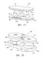
- FIG. 1is a perspective view of an intervertebral implant in a contracted configuration embodying features of the invention.
- FIG. 2a perspective view of the implant shown in FIG. 1 in an expanded configuration.
- FIG. 3is an exploded perspective view of the implant shown in FIG. 1 .
- FIG. 4Ais a top view of the implant shown in FIG. 1 .
- FIG. 4Bis a side cross-sectional view through line 4 B- 4 B of the implant shown in FIG. 4A .
- FIG. 5Ais a perspective view of a lower part of the implant shown in FIG. 1 with upper portions and bottom face removed.
- FIG. 5Bis a bottom view of the lower portion shown in FIG. 5A .
- FIG. 6Ais a perspective view of the upper portion of the implant shown in FIG. 1 with the lower portion removed.
- FIG. 6Bis an enlarged perspective view of the staircase-like lower lock support shown in FIG. 3 .
- FIG. 7is a partial side view of one of the locking mechanisms of the implant shown in FIG. 2 .
- FIGS. 8A-9Bare partial side views of the locking mechanism in FIG. 7 shown in different expanded and locked configurations.
- FIGS. 10A and 10B of the locking mechanismillustrate the expanded but unlocked configuration in FIG. 10A and the expanded and locked configuration in FIG. 10B .
- FIGS. 11A and 11Bare perspective views of the lower lock support and spring locking actuator illustrating the operation thereof.
- FIG. 11Cis a perspective view of an alternate locking mechanism and locking actuator embodying features of the invention.
- FIGS. 12A-12Care perspective views of alternate lower lock support designs embodying features of the invention.
- FIGS. 13A-13Bare perspective and side views respectively of an alternative implant embodying features of the invention which has an articulating top end plate.
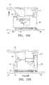
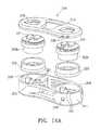
- FIG. 14Ais an exploded perspective view of yet another alternative implant embodying features of the invention which has the lower lock supports within the extendable pistons.
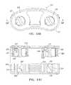
- FIG. 14Bis a top view of the implant shown in FIG. 14A .
- FIG. 14Cis a side cross-sectional view through line 13 C- 13 C of the implant shown in FIG. 14B .
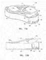
- FIG. 15is a perspective view of an alternate implant design having features of the invention wherein the locking mechanism surrounds a central opening in the top end plate.
- FIG. 16is a perspective view of an alternate implant design having features of the invention wherein the expanding piston is centrally located and locking mechanisms are provided on both sides of the expanding piston.
- FIG. 17is a simplified schematic illustration of an alternate implant design having ratchet and pawl locking members between the top and bottom plates of the implant.
- FIG. 18is a perspective view of an alternative implant design with ratchet and pawl locking members between the top and bottom plates of the implant.
- FIG. 19is a cross sectional perspective view of an implant design with ratchet and cantilevered spring members between the top and bottom plates of the implant.
- FIGS. 20-29schematically illustrate various means for locking an expanding member of implants in extended configurations embodying features of the invention.
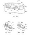
- FIG. 30is a perspective view of yet another alternate implant design having features of the invention wherein the locking mechanism has straight upper and lower interfitting lock supports.
- FIG. 31A-31Gillustrate an alternative implant locking mechanism in which a wire-form surrounds a pair of upper support members with grooves configured to receive the wire-form.
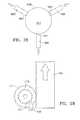
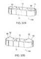
- FIGS. 32A and 32Bare perspective views of a further alternative embodiment of the present invention including locking, conical bone engaging anchors.
- FIGS. 33A-Care perspective views showing alternative bone engaging anchors.
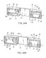
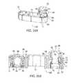
- FIGS. 34A and 34Bare perspective cross sectional views of another alternative embodiment of the present invention including locking, screw-threaded bone engaging anchors.
- FIGS. 35A and 35Bare perspective views of yet another embodiment of the present invention including locking, telescoping bone engaging surfaces.
- FIGS. 1-10BIllustrate an example of an intervertebral implant 10 , a Selectively Expandable Cage (SEC), having features of the invention.
- the implant 10generally includes a housing 11 , a housing base 12 , an interlocking top endplate 13 , a bottom endplate 14 , an interior cavity 15 within the housing 11 and a pair of cylinders 16 .
- Upper lock supports 17are attached to the underside of the top endplate 13 and have multi-stepped lower support surfaces 18 much like an inverted staircase.
- Lower lock supports 20having multi-stepped upper support surfaces 21 surround cylinders 16 much like an upright staircase.
- Pistons 22are secured to the under surface of top endplate 13 .
- Seal members 23are slidably disposed within the cylinders 16 and are mounted on pistons 22 .
- the upper surface 24 of bottom end plate 14is provided with locking actuator channels 25 which partially receive spring locking actuators 26 .
- the base 12 of the housing 11has arcuate slots 27 which are configured to slidably receive the depending elements 28 or locking actuator transfer element of the lower lock supports 20 and partially receive the spring locking actuators 26 .
- Depending elements 28engage the forward end 30 of spring locking actuators 26 .
- the spring locking actuators 26are initially in a compressed configuration so that upon the extension of the top endplate 13 and the attached upper lock supports 17 , the lower lock supports 20 rotate about the cylinders 16 due to the force applied by the biased spring locking actuator 26 .
- the support surfaces 18 of the upper lock supports 17 and the support surfaces 21 of the lower lock supports 20are tiered with multiple steps so that the implant 10 can be locked at several different expanded heights.
- the underside stepped support surfaces 18 of the upper lock support 17may be provided with increasing riser height (alignment faces 46 ) in the upward direction to provide smaller incremental expansion near the end of the piston expansion.
- the stepped support surfaces 21 of the lower lock support 20may be provided with decreasing riser height in the upward direction for the same reason.
- a variety of riser heights of the upper lock support 17 or lower lock support 20can be provided.
- the lowermost stepped support surface 18 of the upper lock support 17 and the uppermost stepped support surface 21 of the lower lock support 20may be provided with various lengths and widths to ensure better support.
- FIG. 2there are two sets of upper lock supports 17 attached to the top endplate 13 and there are two sets of lower lock supports 20 in this embodiment, but a single set or more than two sets of upper and lower lock supports can also be used to lock the implant 10 in the expanded state.
- the implant 10is configured to be implanted between opposing vertebral bodies in the spine to facilitate bony fusion between those vertebral bodies.
- the implant 10is shown in its collapsed or contracted configuration in FIG. 1 and in one example of its expanded configuration in FIG. 2 .
- the implant 10can be inserted easily into the intervertebral body space through a minimal incision and with minimal tissue removal. Once in that space, the implant 10 can be expanded against the two opposing vertebral bodies to distract them and thereby restore height to the intervertebral space. This provides stable opposition of the implant 10 to both vertebral bodies and optimizes the bony fusion process.
- the fusion processcan also be enhanced by filling the interior cavity 15 with autologous bone graft, a bone growth enabling matrix, and/or bone growth stimulating substances prior to and/or after insertion into the body.
- FIGS. 3 , 4 A and 4 BFurther details of individual parts of the implant 10 are depicted in FIGS. 3 , 4 A and 4 B.
- Pistons 22are attached to the underside of the top endplate 13 which are configured to support seal members 23 which run inside of cylinders 16 located in the housing 11 .
- seal members 23which run inside of cylinders 16 located in the housing 11 .
- the seals 23 running inside the cylinders 16 and pistons 22 slidably disposed within the sealsare vertically displaced, translating the top endplate 13 vertically above the housing 11 .
- Lower lock supports 20are located around the outer wall of the cylinders 16 .
- the housing 11comprises an outer wall 31 and cylinders 16 which are secured to housing base 12 .
- the outer wall 31supports a leading nose 32 on the distal end and a delivery boss 33 on the proximal end.
- the leading nose 32has inwardly directed side tapered faces 34 and top tapered face 35 and bottom tapered face 36 . These tapered faces 34 , 35 and 36 enable non-traumatic insertion of the implant 10 passed neural elements and between the vertebral bodies.
- the delivery boss 33contains a delivery tool anchor 37 which allows secure attachment of the implant 10 to a delivery tool (not shown), which is illustrated in copending application Ser. No. 11/535,432, filed Sep. 26, 2006, and Ser. No.
- the delivery boss 33also contains pressure input ports 38 which are used to deliver a pressurized fluid to the interiors of cylinders 16 .
- the outer wall 31 of the housing 11also provides side openings 40 which provide space for bony in-growth into central cavity 15 in the housing 11 and provide radiolucent openings for the radiographic imaging of the process of bony in-growth.
- the housing base 12also contains pressure channels 41 which deliver pressurized fluid from the pressure input ports 38 to the interior of cylinders 16 .
- the housing base 12 of implant 10is depicted with independent pressure channel 41 for each cylinder 16 , other embodiments can contain one or more branching pressure channels for delivering pressurized fluid to two or more cylinders 16 .
- the housing base 12also has locking actuator slots 27 which hold and guide the locking actuators 26 .
- the locking actuator slots 27contain a wider portion, locking actuator opening 42 , to enable insertion of the locking actuator 26 into the channels defined by the locking actuator slots 27 in housing base 12 and the locking actuator channels 25 in the bottom end plate 14 .
- the housing base 12also has optional alignment bosses 19 which align the bottom endplate 14 to the housing 11 via optional alignment holes 9 .
- FIGS. 6A and 6Billustrate further details of the top endplate 13 and the lower lock support 20 .
- the two sets of pistons 22 and upper lock supports 17are joined by connecting members or struts 44 .
- the pistons 22have seal bosses 45 on which the seals 23 are mounted.
- the upper lock supports 17have tiered lower support surfaces 18 and risers or alignment faces 46 .
- the tiered or stepped support surfaces 18 of the upper lock supports 17engage the stepped or tiered support surfaces 21 of the lower lock supports 20 .
- the alignment faces 46 of the upper lock supportare configured to engage the alignment faces 47 of the lower lock supports 20 .
- the uppermost support surface of the lower lock support 20has a lock support stop 50 which engages with the lower most alignment faces 46 of the upper lock support to prevent the lower lock support 20 from over rotating as it engages the upper lock support 17 .
- the bottom of the lower lock support 20also has the locking actuator transfer element 28 which engages the forward end 30 of the spring locking actuator 26 to transfer the actuation force from the locking actuator 26 to the lower lock support 20 .
- FIGS. 7 through 10Bshow details of the selectively expanding locking sequence of implant 10 with the housing 11 removed.
- the collapsed configurationis shown in FIG. 7 with the support surfaces 18 of the upper lock support 17 resting on the support surfaces 21 of the lower lock support 20 .
- the locking actuator 26is a biasing element, such as a spring, that engages the depending element or locking actuator transfer element 28 to urge the alignment faces of the lock supports in a direction where they contact.
- the alignment faces 47 of the lower lock support 17are forced against the alignment faces 46 of the upper lock support 17 .
- the lock support stops 50fit within the lower lock stop relief 52 (shown best in FIG. 6A ) on the top endplate 13 .
- the pistons 22raise the top endplate 13 and attached upper lock supports 17 (straight arrow) moving the support surfaces 18 of the upper lock support 17 off of the support surfaces 21 and moving the lower alignment faces 46 passed the upper alignment faces 47 .
- the locking actuators 26in this embodiment a compressed coiled spring engaging the locking actuator transfer element 28 force the lower lock supports 20 to rotate (curved arrow in FIGS. 8B and 9B ).
- the support surfaces 21 of the rotating lower lock supports 20move to the next lower level of the support surfaces 18 of the raised upper lock supports 17 until the alignment faces 47 of the lower lock supports 20 engage the next level of the alignment faces 46 of the upper lock supports 17 .
- the lower lock support 20 and upper lock support 17then lock the top endplate 13 at this expanded level. This process repeats itself at each locking level ( FIGS. 8A , 8 B, 9 A, 9 B and 10 A) until the top level (or somewhere between) is reached as shown in FIG. 10B .
- the locking actuators 26engage the locking actuator transfer elements 28 and the lower lock supports 20 are rotated so the lowermost alignment surface 46 of the upper lock support 17 engages lock support stop 50 of the uppermost support surface 21 of the lower lock support 20 .
- the lowest support surfaces 18 of the upper lock supports 17 and the highest support surfaces 21are engaged providing all of the locking support.
- the lowest support surfaces 18 of the upper lock supports 17 and the highest support surfaces 21 of the lower lock supports 20can be wider than the other support faces to provide sufficient support material when only these two faces are engaged.
- FIGS. 11A and 11Billustrate the operation of locking actuator 26 .
- the spring locking actuator 26is compressed into an arc beneath the lower lock support 20 .
- One end of the spring locking actuator 26is constrained by the housing 11 (not shown) and the other is engaged with the locking actuator transfer element 28 .
- the locking actuator 26pushes against the locking actuator transfer element 28 and rotates the lower lock support 20 in a clockwise direction (arrow) as viewed from above.
- the angular orientation of the tiered upper and lower support surfaces 18 and 21can vary when there is more than one set of supports. As shown in FIG. 3 the proximal lower support surfaces 21 are oriented clockwise as viewed from above and the distal lower support surfaces 21 are oriented counter-clockwise. This opposite orientation provides enhanced locking support for rotational forces applied to the implant.
- FIG. 11CAn alternate locking actuator 26 a is shown in FIG. 11C as a torsion spring.
- This locking actuator 26 ahas constraining tab 53 secured to the lower lock support 20 and constraining tab 54 secured to the housing 11 a .
- the torsion spring in FIG. 11Cdoes the same.
- An extension springwould work equally as well as a locking actuator 26 a .
- Spring actuatorscan be made of an appropriate biocompatible material such as stainless steel, NITINOL, titanium or a suitable polymer. Locking actuators are not limited to springs.
- a wide variety of mechanismscan be used to actuate the lower lock supports 20 , including but not limited to, a linear drive, an externally actuated tensile member, a worm gear, an inflated member such as a balloon or bellows, a magnet, a rotational drive such as a micro motor, a super elastic shape memory element, and the like.
- FIG. 12A through 12Cshow variations of the lower lock support 20 described above.
- a tri-set lock support 20 ais shown whereby there is are three sets of upper support surfaces 21 a , upper alignment surfaces 47 a and lock support stops 50 rather than the 2 sets described above.
- This tri-set lower lock support 20 ahas two advantages over the 2 sets design, 1) there are three support columns rather than two locking the implant 10 in an expanded state thereby creating a more stable lock and 2) the tri-set lower lock support— 20 a has to move or rotate much less for each locking level.
- This last advantageis significant when the locking actuator is a spring such as spring locking actuator 26 as this places less strain on the spring to achieve the required locking force at each step.
- Each lower lock support columnwill have a corresponding upper lock support column (not shown).
- the upper support surfaces 21 and lower support surfaces 18are not limited to 2 or 3 sets of surfaces. Any number of sets of support surfaces including a single set may be employed.
- FIG. 12Bshows an inter-digitating lower lock support 20 b .
- Each of the inter-digitating upper support surfaces 21 b on the inter-digitating lock support 20 bis paired with an inter-digitating stop 50 b which when paired with matching inter-digitating support surfaces and stops of an upper lock support (not shown) prevents the inter-digitating support surfaces 21 b from moving relative to the inter-digitating support surfaces of an upper lock support to unlock the implant 10 b without the inter-digitating lower support faces first lifting above the inter-digitating stop 50 b .
- This designprovides an enhanced locking feature.
- the locking support 20 c shown in FIG. 12Cprovides an enhanced locking feature by providing inclined support surfaces 21 c which have a slope relative to the horizontal which requires matching inclined lower support surfaces on the upper lock supports (not shown) to be lifted above the inclined upper support surfaces 21 c before the upper lock support can be rotated to unlock the implant 10 c.
- FIGS. 12A and 12Cshow various lengths of locking actuator transfer elements or depending elements 28 .
- the locking actuator transfer element 28can vary in length depending on how much engagement is desired between the locking actuator transfer element 28 and the locking actuator slots 27 .
- the locking actuator transfer element 28includes one or more transfer element tabs 29 a and 29 c which vertically constrain the lower lock support 20 to the locking actuator slots 27 in the housing 11 .
- the wider locking actuator opening 42 described aboveenables insertion of the locking actuator transfer element 28 with transfer element tabs 29 a and 29 c into the locking actuator slots 27 in housing base 12 at the rotational position where the locking actuator transfer element 28 is aligned with the locking actuator opening 42 . In other rotational positions the transfer element tabs are constrained by lateral extensions 49 (shown in FIG.
- the locking actuator transfer element 28provides both the function of transferring force from the locking actuator 26 to the lower lock support 20 as well as constraining the lower lock support 20 to the housing 11 .
- This later functionprevents the frictional forces between the lower alignment faces 46 and the upper alignment faces 47 created by the biased spring locking actuator 26 from lifting the lower lock support 20 along with the upper lock support 17 when the upper lock support 17 is lifted by the piston 22 .
- FIG. 12Bdepicts a locking actuator guide channel 80 .
- This locking actuator guide channel 80engages a tensile member (not shown) which transfers actuation force from the locking actuator 26 to the lower lock support 20 .
- Tensile memberscan be an of a number of known elements such as sutures made of polymers or natural materials, metal cable, plastic or metal rod and the like.
- FIGS. 13A and 13Billustrate an alternate design of an implant 110 embodying features of the invention.
- the implant 110has independent actuation of the distal piston 122 a and proximal piston 122 b .
- the two pistons 122 a and 122 bare interconnected by an articulating top endplate 113 which allows independent lift and locking of each side of the implant 110 .
- This independent lift and locking of both ends of the implant 110enables the implant to conform to intervertebral endplates that have uneven lateral heights between them. Further, this independent lift and locking allows the implant 110 to be used to create varying lateral heights between vertebral endplates which can be useful to compensate for a scoliosis in the spine.
- Implant 110has a housing 111 which has an alternate delivery tool anchor 160 located in it as well as alternate pressure input ports 137 .
- a variety of anchor design or pressure portscan be used with any of the embodiments of the current device without departing from the scope of this invention.
- Lock and unlock access ports 138are also located on this housing 111 . These ports are used to guide lock and unlock mechanisms (not shown) which can be manipulated externally to the implant 110 to actuate the lower lock support 120 to not only move it under the upper lock support 117 to hold the piston 122 b and articulating endplate 113 in an expanded position, but also to move the lower lock support 120 away from the upper lock support 117 to allow the piston 122 b and articulating endplate 113 to collapse back into the housing 110 .
- lock/unlock mechanismcan be used with the current invention such as but not limited by, a tensile member including suture thread and metallic cable, a compressive member such as a metallic or polymer rod, pressurized fluid, a rotating drive, a super elastic shape memory element, and the like.
- FIGS. 14A-14Cdepict yet another alternate implant 210 that embodies features of the invention.
- Implant 210has an interfacing top plate 213 which connects to separate and freely rotating pistons 222 via the piston capture plate 270 on the interfacing top plate 213 and the piston heads 318 on the rotating pistons 222 ab .
- the rotating pistons 222 abalso interiorly contain upper lock supports 217 with support faces 218 and alignment faces 246 .
- Seals 223are mounted on the rotating pistons 222 ab and the seals 223 and rotating pistons 222 ab fit into internal cylinders 216 that are located on the housing 211 .
- the internal cylinders 216have lower lock supports 220 with support surfaces 221 and alignment faces 247 as well as lower retaining features 273 .
- the housing 211also contains one or more pressure input ports 238 .
- the implant 210is inserted into the intervertebral body space in a collapsed state and fluid pressure is delivered through the pressure input port(s) 238 to the internal cylinder(s) 216 to raise the seal(s) 223 and rotating piston(s) 222 ab out of the internal cylinder(s) thereby raising the interfacing top plate 213 and expanding the implant 210 .
- an actuatorrotates the rotating pistons 222 ab such that the lower support surfaces 218 of the upper lock supports 217 are moved above the upper support surfaces 221 of the lower lock supports 220 , to thereby lock the implant 210 in the expanded configuration.
- the actuatorcan be one or more tensile members such as suture threads or cables that extend from the user into the implant 210 through the lock and unlock access ports 238 on the interfacing top plate 213 to the piston head 271 .
- Applying tension to one or more tensile members when the piston is in an extended configurationwill rotate the piston heads 271 such that the support surfaces 218 of upper lock supports 217 are moved above the support surfaces 221 of the lower lock supports 220 thereby locking the implant 210 .
- apply tension to one or more tensile memberswill rotate the piston heads 271 such that the lower support surfaces 218 are moved away from the upper support surfaces 221 thereby unlocking the implant 210 and allowing the rotating pistons 22 ab 2 to seat back into the internal cylinders 216 such that the implant 210 is once again in a collapsed configuration.
- FIG. 15illustrates an alternate implant design 310 embodying features of the invention which has a housing 311 , top end plate 313 and pistons 322 similar to the prior embodiments.
- This implant 310has upper lock supports 317 and lower lock supports 320 within a central portion of the implant.
- the upper lock supports 317are secured to the top end plate 313 and the lower lock supports 320 are secured to the base 314 with depending elements (not shown) as was described above and are moved as in the prior embodiments.
- FIG. 16illustrates an alternate implant design 410 embodying features of the invention which has a housing 411 , top end plate 413 and a centrally located piston 422 similar to the prior embodiments.
- This implant 410has upper lock supports 417 and lower lock supports 420 distal and proximal to the centrally located cylinder 416 and piston 422 .
- the upper lock supports 417are secured to the top end plate 413 and the lower lock supports 420 are secured to the base 412 and are moved as in the prior embodiments via depending elements (not shown) as was described above.
- FIG. 17shows another alternate implant 510 which has a pair of pistons 522 and which has a locking support system which includes ratchets 520 on the base 512 and pawls 517 pivotally mounted to and depending from the top end plate 513 . Expansion of the pistons 522 causes the free ends 518 of pawls 517 to engage recesses 520 in the ratchets 521 so as to lock the top end plate 513 in an extended configuration.
- FIG. 18illustrates another alternative implant design 610 which is similar to that shown in FIG. 17 .
- the free end of the pawl 617has a plurality of teeth 618 to provide greater effective contact between the pawl 617 and the ratchet 621 for locking of the implant 610 .
- FIG. 19is the cross section of another embodiment of implant 710 embodying features of the invention.
- the pistons 722are surrounded by upper lock support 717 which has at least one cantilever extension ending at the support surface 718 .
- the support surfaces 718are captured by the recessed support surfaces 721 which are located on the inner wall of the housing 711 .
- the support surfaces 718 of the upper lock support 717engages the recessed support faces 721 locking the implant 710 in place.
- the upper lock support 717can be rotated relative to the piston 722 and housing 711 to disengage the support surfaces 718 from the support faces 721 to unlock the implant 710 and lower the pistons 722 as needed.
- the implant 710can be unlocked by rotating the upper lock support constraints 775 relative to the upper lock support 717 to press on the cantilever extensions and disengage the support surfaces 718 from the support surfaces 721 .
- FIGS. 20A-31illustrate a variety of suitable means for locking extendable members such as pistons in extended configurations.
- FIGS. 20A , 20 B, 21 A, 21 B, and 22 - 31show variations of lower lock supports and upper lock supports. In each of these variations there are support surfaces on the lower lock supports which engage support surfaces on the upper lock supports.
- support surfaces 818comprise grooves set into the upper lock support 817 .
- the lower lock support 820is a U-shaped tong which is configured to advance (as indicated by the arrow in FIG. 20A ) towards the upper lock support 817 and to engage one of the grooves with its upper support surface 821 for locking an implant not shown in these drawings.
- Lower lock support 820is withdrawn (as indicated by the arrow in FIG. 20B ) from the groove to disengage the lower lock support and unlock the implant.
- the lower lock support 920is a plate with an upper lock clearance opening 970 that is shaped to allow passage of the cylindrical flat sided upper lock support 917 through the lower lock support 920 (arrow).
- FIG. 21Bonce the lower lock support 920 is positioned at the desired location it can be rotated approximately 90° (arrow) to engage the support faces of the lower lock support 920 with the support surfaces 918 of the upper lock support 917 .
- the shape of the upper lock support 917 and mating upper lock clearance opening 970 on the lower lock support 920are not restricted to the profile shown in FIGS. 21A and 21B nor is the locking actuation restricted to 90° rotation of one of the elements but can vary to any number of shapes that allow passage in one configuration but constraint when one of the elements is moved to another configuration.
- the upper lock support 1017is a cylinder with notches cut to create support surfaces 1018 .
- the lower lock support 1020is a pivoting pin 1070 with a pawl 1071 for the lower support surface 1021 .
- the support surfaceis biased as indicated by the arrow 1072 to allow the upper lock support 1017 to rise with an expandable member of an implant and to prevent the upper lock support from dropping. This allows the device to lock at each level when the subsequent support surface 1018 of the upper lock support 1017 engages the support surface 1021 of the lower lock support 1020 .
- the upper lock support 1017can also be lowered by moving the pivoting pin 1070 of the lower lock support 1020 away from the upper lock support 1017 to disengage the support surface 1021 from the support surface 1018 .
- FIG. 23shows yet another embodiment having features of the invention where the lower lock support 1120 is a pin configured to engage (arrow) support surfaces 1118 located in the upper lock support 1117 .
- the lower lock support 1120does not have to engage the full thickness of the upper lock support 1117 as shown in this figure, nor does the support surface 1118 have to extend through the entire thickness of the upper lock support 1117 but rather can engage any portion of the upper lock support 1117 that is sufficient to lock an implant in position.
- This embodimentalso allows a variety of shapes of pins 1120 and matching support surfaces 1118 .
- the lower lock support 1220is a grip with two pivoting jaws 1270 , the ends of which have support surfaces 1221 .
- the upper lock support 1217has a series of notches 1271 which have the support surfaces 1218 .
- a lock actuatorsuch as a compressive spring (not shown) can apply force (as shown by the arrows 1272 ) to the grip base extensions 1273 to lock the device.
- This variationhaving features of the invention allows the upper lock support 1217 to move upwards but prevents downward motion thereof. Downward motion of the upper lock support 1217 can be allowed by reversing the force on grip base extensions 1273 .
- the upper lock support 1317has one or more flat faces as the support surfaces 1318 .
- the lower lock support 1320has one or more pivoting pawls that have a support surface 1321 that engage the support surface 1318 and supports a load (arrow).
- the upper lock support 1417has an exterior support face 1418 which is gripped by the support face 1421 on the inner diameter of the wrapped lower lock support 1420 .
- This lower lock support 1420can be a torsion spring that in its free state grips the upper lock support 1417 and releases the upper lock support when a force (arrows) is applied to one or more of its ends 1470 as shown to increase the spring's inner diameter. The reverse is possible where in its free state the lower lock support 1420 allows movement of the upper lock support 1417 inside the inner diameter. When a tensile force is applied to the ends 1470 to reduce the inner diameter, the lower lock support grips the support surface 1418 of the upper lock support 1417 to lock the implant.
- FIGS. 27A and 27Bshow another variation which can be described as a canted washer type device.
- the lower lock support 1520is a plate with an upper lock clearance opening 1570 which allows relative movement of the upper lock support 1517 as shown in FIG. 27A .
- the edge of the upper lock clearance opening 1570comprises a lower support surface 1521 which engages the upper support surface 1518 which is the outer surface of the upper lock support 1517 locking it relative to the lower lock support 1520 .
- FIG. 28Yet another variation of the gripping lock of the current invention is shown in FIG. 28 .
- the lower lock support 1620comprises of one or more jaws which have support surfaces 1621 that are configure to be forced against the support surface 1618 of the upper lock support 1617 to produce friction to lock the device in place.
- FIG. 29illustrates a lower lock support 1720 which comprises a pivot and pawl as has been detailed above.
- the end of the pawlcomprises a lower support surface 1721 which engages an upper support surface 1718 on the upper lock support 1717 .
- the upper lock support 1717is rotated counter clockwise by an expanding element (not shown). This rotation in turn raises the piston 1722 which expands the implant.
- the upper lock support 1817is integrated into the lifting mechanism to engage the lower lock support 1720 and lock the implant as it expands.
- FIG. 30illustrates yet another alternative implant 1810 , similar to that shown in FIG. 1 except that the upper locking member 1817 and lower locking member 1818 have a linear shape rather than the arcuate shape of the prior embodiments.
- the implant 1810generally has a housing 1811 , a top plate 1813 , a bottom plate 1814 , pistons 1822 and cylinders 1816 .
- the upper locking member 1817has support surfaces 1818 and the lower locking member 1820 has support surfaces 1821 .
- the implant 1810has a locking actuator (not shown).
- FIGS. 31A-31Gillustrates another implant 1910 embodying features of the invention which has upper locking members 1917 with grooves 1970 having support surfaces 1918 and lower locking member 1920 with locking surfaces 1921 .
- the lower locking member 1920is a wire-form which encircles the exterior of both upper locking members 1917 and is configured to seat within the grooves 1970 . Expansion of the lower locking member 1920 (arrows in FIG. 31B ) by the locking actuator (not shown) causes the lower locking member 1920 to be pulled out of the groove 1970 and allows the upper locking member 1917 to rise with the expansion of the implant. Release of this expansion of the lower locking member 1920 (arrows in FIG. 31A ) allows the lower locking member 1920 to seat back into the groove 1970 locking the implant 1910 .
- FIG. 31Gillustrates a detail of an alternate implant 1910 a embodying features of the invention which has upper locking members 1917 a with grooves 1970 a having support surfaces 1918 a and lower locking member 1920 a with locking surfaces 1921 a .
- the lower locking member 1920 ais a wire-form which encircles the exterior of both upper locking members 1917 a and is configured to seat within the grooves 1970 a .
- the support surface 1918 alocks on the supports surface 1921 a when there is a compressive or downward force (hollow arrow) on the upper locking member 1917 a locking the implant 1910 a .
- Upward force or extension (solid arrow) of the upper locking member 1917 acauses the lower locking member 1920 a to ride on the disengaging surface 1919 a and out of the groove 1970 a allowing the upper locking member 1917 a to rise with the expansion of the implant 1910 a.
- a piston/cylinder and locking arrangement as described abovemay be used to deploy extendable bone anchors.
- implant 10 A with conical bone engaging anchors 60 as shown in FIGS. 32A and 32Bmay be constructed with pistons 22 and cylinders 16 as described above in connection with implant 10 and shown, for example, in FIGS. 2 , 3 and 4 B.
- Implant 10 Ahas a housing 11 as previously described and may include other previously described features such as interior cavity 15 for bone growth stimulating substances.
- the two pistons 22instead of upper interlocking endplate 13 , individually terminate with conical bone engaging anchors 60 .
- the bone engaging anchors, including sharp leading tip 62form surface for engaging the vertebral body.
- bone engaging anchors 60are in a contracted configuration, within housing 11 , to facilitate insertion of implant 10 A.
- bone engaging anchors 60are moved to an extended configuration as shown in FIG. 32B , wherein at least leading tip 62 extends beyond housing 11 to engage and anchor in the bone.
- locking mechanismsincluding multi-stepped upper and lower lock supports 17 , 20 as previously described in connection with implant 10 and shown, e.g. in FIGS. 6A-12C , are provided to support each anchor 60 in the extended configuration. With this arrangement, the extended and locked anchor 60 helps to retain the implant in place.
- implant 10 B in FIG. 33Aincludes bone engaging anchors formed as spike 60 A and blade 60 B.
- Blade 60 Bcan be particularly effective in preventing motion along the insertion path after deployment.
- the length of the Blade 60 Bis aligned in the direction shown by arrow A. This is substantially orthogonal to the direction of implantation (arrow B) and would resist movement in that direction.
- Implant 10 F, shown in FIG. 33Bincludes further possible variations.
- the bone engaging anchorsare formed as barbed spikes 60 C.
- lateral anchor 63for anchoring in laterally oriented tissue.
- lateral anchor 63includes a plain spike 60 A.
- Lateral anchor 63is formed in the same manner and with the same components, i.e. piston, cylinder, locking mechanism, etc. as elsewhere described in this application, except that the components are oriented laterally as shown.
- housing 11includes a central member 11 A that divides interior cavity 15 into two portions.
- FIG. 33Cshows a further alternative implant 10 G, including anchors 65 extending obliquely from housing 11 , rather than orthogonally. This oblique arrangement is helpful in resisting side to side rotational forces (for example when the patient/spine bends towards the side) and expansion forces.
- obliquely extending anchors 65are essentially identical to other bone engaging anchors described herein except for the oblique orientation.
- holes 68are provided in top endplate 66 for the spikes to pass through.
- bone engaging anchors according to embodiments of the inventionshould have a relatively small termination (e.g.
- implant 10 Cincludes screw-threaded members 64 as bone engaging anchors.
- Implant 10 Calso illustrates a further alternative wherein the bone engaging surfaces, such as the anchors, extend from opposite sides of the implant.
- interlocking endplate 13is replaced with an integrated top endplate 66 .
- Holes 68are provided for threaded member 64 to pass through. Persons of ordinary skill in the art will appreciate that holes 68 will be located as needed; in the illustrated embodiment one is in endplate 66 and the other in bottom endplate 14 .
- Threaded bone engaging anchors 64extend outwardly from pistons 22 .
- the inner wall of housing 11is provided with a screw-threaded surface 70 that mates with corresponding threads 71 cooperating with pistons 22 .
- seals 23act between the pistons 22 and cylinders 16 to prevent leakage of hydraulic fluid.
- locking mechanismsas previously described and shown, for example, in FIGS. 6A-12C , may be employed to prevent the bone engaging anchors from becoming unengaged from the bone.
- upper and lower lock supports 17 , 20are visible around the outside of the piston and cylinders.
- use of a separate locking mechanismmay not be required.
- the configuration of the threads alonemay be sufficient to prevent the anchors from backing out.
- FIGS. 35A and 35Billustrate a further aspect of the present invention wherein locking mechanisms as described are utilized to secure telescoping bone engaging surfaces in place.
- telescopingrefers to nested, extendable members including at least one intermediate member between a base and bone engaging member.
- implant 10 Dhas substantially planar bone engaging members 72 .
- Bone engaging members 72are thus similar to the bone engaging members of implant 10 , but instead individually actuated without interlocking endplate 13 .
- the piston/cylinder arrangementis also similar to that previously described except that here upper piston 74 is received in intermediate piston 80 .
- Intermediate pistonis in turn received in cylinder 16 as was previously described for piston 22 .
- Upper piston 74is sealed against intermediate cylinder 78 of intermediate piston by upper piston seals 76 (see FIG. 35B ).
- the telescoping bone engaging members 72are secured by locking mechanisms in a similar manner to the earlier described embodiments, with the addition of an upper lock support 82 for the upper piston.
- Intermediate piston 80is supported by upper lock support 17 and lower lock support 20 as previously described.
- Upper lock support 82includes upper and lower lock supports 84 , 86 .
- upper piston 74is secured to upper lock support 84 of the upper lock set.
- Lower lock support 86 of the upper lock setis mounted on top of upper lock support 17 of the lower lock set.
- One difference from the earlier described embodimentsis that separate spring actuators 26 are not required for the upper lock set as they may be rotated along with the lower lock set by actuators 26 .
- Implant 10 Eas shown in FIG. 35B includes a further variation in which the planar portion of upper bone engaging surface 88 is effectively annular with a conical anchor 90 at the center.
- Advantages of embodiments of the present invention including bone engaging anchorsinclude the ability of the anchors to be extended lateral from the long axis of the implant (i.e., the insertion axis) with a relatively high force using the relatively small connection to the implant of the hydraulic line. This is an advantage over other methods that require larger access or larger connections to the implant for lager tools or non-hydraulic extension forces to extend the anchors into the hard, bony tissue.
- a lateral cage implantas illustrated for exemplary embodiments of the present invention herein, is particularly advantaged by the use of anchors as described herein because the lateral approach to the spine is a long and narrow approach, which limits the ability of the surgeon to use other instrumentation to extend anchors from the cage (as can be done more readily, for example, with an anterior approach where the access is not as narrow).
- anchors according to embodiments of the present inventionare advantageous for any approach as they can produce the required extension forces regardless of patient anatomy or other restrictions on the use of alternate extension means by the surgeon.
- the description hereinfocused on the manner in which the locking elements are configured to lock the implant in extended configurations. Although this locking action resists the forces placed on the implant that would tend to force it back into a collapsed configuration that is not the only force the locking elements address. Once inserted between vertebral bodies the implant is subject to lateral forces and torsion moments as well as compressive forces.
- the locking features along with the other elements of the inventionare designed to resist all of these forces to provide an implant that provides stable fixation and distraction.
- a partial or complete discectomyis usually performed prior to the insertion of the spinal implant having features of the invention between vertebral bodies.
- the implantis introduced in its unexpanded state to enable it to be inserted posteriorly with minimal trauma to the patient and risk of injury to nerve roots. Once in place the implant can be expanded to provide both medial and lateral spinal correction.
- the implanthas an unexpanded height of about 5 to about 15 mm, typically about 7 mm and is expandable to at least 130% to about 180% of the unexpanded height.
- the implantis about 9 to about 15 mm wide, typically about 12 mm wide and about 25 to about 55 mm long, typically about 35 mm long to facilitate minimally invasive insertion and thereby minimize trauma to the patient and risk of injury to nerve roots.
- the implantincluding its various components should be formed of biocompatible, substantially incompressible material such as PEEK or titanium, and preferably type 6-4 titanium alloy or other suitable materials which will allow for long term deployment within a patient.
- extendable members or pistonsmay be individually controlled so that the physician is able to provide a controlled angle of the corrective implant surface. While only two extendable members or pistons are described herein, the implant may be provided with three or more individually extendable members so that the physician can exercise three-dimensional control of the implant extension.
- the implants described hereinare expanded by hydraulic fluid.
- Other expansion meansmay be employed.
- a screw mechanismmay be employed to expand the implant into engagement with adjacent vertebral surfaces.
- the implantcan be provided with load or pressure sensors that register differential pressure and pressure intensity exerted on the engaging surfaces of the SEC by the patient's vertebrae end plates to generate corrective signals, for example by computer control, that are used, e.g. by the surgeon or by a computer controlled mechanism to realign the patient's spine.
- the inventionmay further include a system that makes these adjustments, responsive to sensor signals, in real time and on a continual basis, such that the shapes of the implant changes to realign the patient's spine or mechanism.
- such systemis contemplated for use in setting the positions of the pistons during installation of the implant.
Landscapes
- Health & Medical Sciences (AREA)
- Engineering & Computer Science (AREA)
- Biomedical Technology (AREA)
- Orthopedic Medicine & Surgery (AREA)
- Neurology (AREA)
- Heart & Thoracic Surgery (AREA)
- Oral & Maxillofacial Surgery (AREA)
- Transplantation (AREA)
- Cardiology (AREA)
- Vascular Medicine (AREA)
- Life Sciences & Earth Sciences (AREA)
- Animal Behavior & Ethology (AREA)
- General Health & Medical Sciences (AREA)
- Public Health (AREA)
- Veterinary Medicine (AREA)
- Prostheses (AREA)
- Surgical Instruments (AREA)
Abstract
Description
Claims (59)
Priority Applications (13)
| Application Number | Priority Date | Filing Date | Title |
|---|---|---|---|
| US12/548,260US8435296B2 (en) | 2008-02-22 | 2009-08-26 | Hydraulically actuated expanding spine cage with extendable locking anchor |
| JP2011540880AJP5814794B2 (en) | 2008-12-10 | 2009-12-10 | Lockable expanding spine retainer |
| EP09832515.2AEP2370026B1 (en) | 2008-12-10 | 2009-12-10 | Lockable expanding spine cage |
| EP15179587.9AEP3009106B1 (en) | 2008-12-10 | 2009-12-10 | Lockable expanding spine cage |
| CN200980156465.3ACN102316827B (en) | 2008-12-10 | 2009-12-10 | Lockable expanding spine cage |
| AU2009324608AAU2009324608B2 (en) | 2008-12-10 | 2009-12-10 | Lockable expanding spine cage |
| PCT/US2009/067446WO2010068725A2 (en) | 2008-12-10 | 2009-12-10 | Lockable expanding spine cage |
| US13/858,360US8956413B2 (en) | 2008-02-22 | 2013-04-08 | Hydraulically actuated expanding spine cage with extendable locking anchor |
| US14/644,969US9545316B2 (en) | 2008-02-22 | 2015-03-11 | Adjustable distraction cage with linked locking mechanisms |
| JP2015184855AJP6032447B2 (en) | 2008-12-10 | 2015-09-18 | Lockable expanding spine retainer |
| US15/377,377US10342673B2 (en) | 2008-02-22 | 2016-12-13 | Adjustable distraction cage with linked locking mechanisms |
| US16/504,495US11191647B2 (en) | 2008-02-22 | 2019-07-08 | Adjustable distraction cage with linked locking mechanisms |
| US17/535,148US12232975B2 (en) | 2008-02-22 | 2021-11-24 | Lockable spinal implant |
Applications Claiming Priority (4)
| Application Number | Priority Date | Filing Date | Title |
|---|---|---|---|
| US12/072,044US8932355B2 (en) | 2008-02-22 | 2008-02-22 | Spinal implant with expandable fixation |
| US20151808P | 2008-12-10 | 2008-12-10 | |
| US12/380,840US20100145455A1 (en) | 2008-12-10 | 2009-03-04 | Lockable spinal implant |
| US12/548,260US8435296B2 (en) | 2008-02-22 | 2009-08-26 | Hydraulically actuated expanding spine cage with extendable locking anchor |
Related Parent Applications (2)
| Application Number | Title | Priority Date | Filing Date |
|---|---|---|---|
| US12/072,044Continuation-In-PartUS8932355B2 (en) | 2008-02-22 | 2008-02-22 | Spinal implant with expandable fixation |
| US12/380,840Continuation-In-PartUS20100145455A1 (en) | 2008-02-22 | 2009-03-04 | Lockable spinal implant |
Related Child Applications (2)
| Application Number | Title | Priority Date | Filing Date |
|---|---|---|---|
| PCT/US2009/067446ContinuationWO2010068725A2 (en) | 2008-02-22 | 2009-12-10 | Lockable expanding spine cage |
| US13/858,360DivisionUS8956413B2 (en) | 2008-02-22 | 2013-04-08 | Hydraulically actuated expanding spine cage with extendable locking anchor |
Publications (2)
| Publication Number | Publication Date |
|---|---|
| US20100057204A1 US20100057204A1 (en) | 2010-03-04 |
| US8435296B2true US8435296B2 (en) | 2013-05-07 |
Family
ID=42231957
Family Applications (5)
| Application Number | Title | Priority Date | Filing Date |
|---|---|---|---|
| US12/380,840AbandonedUS20100145455A1 (en) | 2008-02-22 | 2009-03-04 | Lockable spinal implant |
| US12/384,622Expired - Fee RelatedUS8192495B2 (en) | 2008-12-10 | 2009-04-07 | Lockable spinal implant |
| US12/548,260Active2029-10-13US8435296B2 (en) | 2008-02-22 | 2009-08-26 | Hydraulically actuated expanding spine cage with extendable locking anchor |
| US13/486,679Active2029-04-07US8894710B2 (en) | 2008-12-10 | 2012-06-01 | Lockable spinal implant |
| US13/858,360ActiveUS8956413B2 (en) | 2008-02-22 | 2013-04-08 | Hydraulically actuated expanding spine cage with extendable locking anchor |
Family Applications Before (2)
| Application Number | Title | Priority Date | Filing Date |
|---|---|---|---|
| US12/380,840AbandonedUS20100145455A1 (en) | 2008-02-22 | 2009-03-04 | Lockable spinal implant |
| US12/384,622Expired - Fee RelatedUS8192495B2 (en) | 2008-12-10 | 2009-04-07 | Lockable spinal implant |
Family Applications After (2)
| Application Number | Title | Priority Date | Filing Date |
|---|---|---|---|
| US13/486,679Active2029-04-07US8894710B2 (en) | 2008-12-10 | 2012-06-01 | Lockable spinal implant |
| US13/858,360ActiveUS8956413B2 (en) | 2008-02-22 | 2013-04-08 | Hydraulically actuated expanding spine cage with extendable locking anchor |
Country Status (6)
| Country | Link |
|---|---|
| US (5) | US20100145455A1 (en) |
| EP (2) | EP3009106B1 (en) |
| JP (2) | JP5814794B2 (en) |
| CN (1) | CN102316827B (en) |
| AU (1) | AU2009324608B2 (en) |
| WO (1) | WO2010068725A2 (en) |
Cited By (99)
| Publication number | Priority date | Publication date | Assignee | Title |
|---|---|---|---|---|
| US20100286779A1 (en)* | 2009-05-06 | 2010-11-11 | Thibodeau Lee L | Expandable spinal implant apparatus and method of use |
| US20130253650A1 (en)* | 2008-12-10 | 2013-09-26 | Coalign Innovations, Inc. | Adjustable Distraction Cage With Linked Locking Mechanisms |
| US20140135933A1 (en)* | 2008-02-07 | 2014-05-15 | K2M, Inc. | Expandable vertebral device with cam lock |
| US9149364B2 (en) | 2008-03-07 | 2015-10-06 | DePuy Synthes Products, Inc. | Expandable interbody spacer device |
| US9211195B2 (en) | 2009-10-13 | 2015-12-15 | Nicholas Poulos | Expandable interbody implant and method |
| US9216096B2 (en) | 2010-03-16 | 2015-12-22 | Pinnacle Spine Group, Llc | Intervertebral implants and related tools |
| US20160022342A1 (en)* | 2014-07-23 | 2016-01-28 | Renovis Surgical Technologies, Inc. | Modular surgical tool assembly |
| US9320610B2 (en) | 2011-08-16 | 2016-04-26 | Stryker European Holdings I, Llc | Expandable implant |
| US9380932B1 (en) | 2011-11-02 | 2016-07-05 | Pinnacle Spine Group, Llc | Retractor devices for minimally invasive access to the spine |
| US9393130B2 (en) | 2013-05-20 | 2016-07-19 | K2M, Inc. | Adjustable implant and insertion tool |
| US9445914B2 (en) | 2010-09-30 | 2016-09-20 | Stryker European Holdings I, Llc | Surgical implant with guiding rail |
| US9707100B2 (en) | 2015-06-25 | 2017-07-18 | Institute for Musculoskeletal Science and Education, Ltd. | Interbody fusion device and system for implantation |
| US9717604B2 (en) | 2008-03-31 | 2017-08-01 | Stryker European Holdings I, Llc | Spinal implant apparatus and methods |
| US9782271B2 (en) | 2008-02-28 | 2017-10-10 | Stryker European Holdings I, Llc | Expandable intervertebral implant |
| US9814600B2 (en) | 2005-09-26 | 2017-11-14 | Howmedica Osteonics Corp. | Selectively expanding spine cage with enhanced bone graft infusion |
| US9931222B2 (en) | 2008-02-22 | 2018-04-03 | Howmedica Osteonics Corp. | Spinal implant with expandable fixation |
| US9974662B2 (en) | 2016-06-29 | 2018-05-22 | Globus Medical, Inc. | Expandable fusion device and method of installation thereof |
| US10052215B2 (en) | 2016-06-29 | 2018-08-21 | Globus Medical, Inc. | Expandable fusion device and method of installation thereof |
| US10070970B2 (en) | 2013-03-14 | 2018-09-11 | Pinnacle Spine Group, Llc | Interbody implants and graft delivery systems |
| US10219914B2 (en) | 2015-11-10 | 2019-03-05 | Globus Medical, Inc. | Stabilized expandable intervertebral spacer |
| US10292833B2 (en) | 2013-11-27 | 2019-05-21 | Howmedica Osteonics Corp. | Structurally supporting insert for spinal fusion cage |
| US10314718B2 (en)* | 2016-09-22 | 2019-06-11 | Loubert S. Suddaby | Expandable intervertebral fusion implant |
| US10342675B2 (en) | 2013-03-11 | 2019-07-09 | Stryker European Holdings I, Llc | Expandable implant |
| US10470891B2 (en) | 2016-09-12 | 2019-11-12 | Howmedica Osteonics Corp. | Interbody implant with independent control of expansion at multiple locations |
| US10485675B2 (en) | 2016-10-26 | 2019-11-26 | Howmedica Osteonics Corp. | Expandable interbody implant with lateral articulation |
| US10548743B2 (en) | 2014-12-16 | 2020-02-04 | Globus Medical, Inc. | Expandable fusion devices and methods of installation thereof |
| US10548738B2 (en) | 2016-04-07 | 2020-02-04 | Howmedica Osteonics Corp. | Expandable interbody implant |
| US10596010B2 (en) | 2017-09-18 | 2020-03-24 | Loubert S. Suddaby | Stand-alone expandable interbody spinal fusion device with locking mechanism |
| US10729553B2 (en) | 2017-09-15 | 2020-08-04 | Stryker European Operations Holdings Llc | Intervertebral body fusion device expanded with hardening material |
| US10864086B2 (en) | 2010-02-24 | 2020-12-15 | Globus Medical, Inc. | Expandable intervertebral spacer and method of posterior insertion thereof |
| US10940018B2 (en) | 2016-05-20 | 2021-03-09 | Howmedica Osteonics Corp. | Expandable interbody implant with lordosis correction |
| USRE48719E1 (en) | 2014-10-09 | 2021-09-07 | K2M, Inc. | Expandable spinal interbody spacer and method of use |
| US11191650B2 (en) | 2020-02-03 | 2021-12-07 | Globus Medical Inc. | Expandable fusions devices, instruments, and methods thereof |
| US11207192B2 (en) | 2017-01-26 | 2021-12-28 | Loubert S. Suddaby | Stand-alone expandable interbody spinal fusion device with integrated fixation mechanism |
| US11219532B2 (en) | 2017-09-18 | 2022-01-11 | Loubert S. Suddaby | Stand-alone expandable interbody spinal fusion device with locking mechanism |
| US11298240B2 (en) | 2020-06-16 | 2022-04-12 | Globus Medical, Inc. | Expanding intervertebral implants |
| US11357640B2 (en) | 2020-07-08 | 2022-06-14 | Globus Medical Inc. | Expandable interbody fusions devices |
| US11491020B2 (en) | 2020-07-09 | 2022-11-08 | Globus Medical, Inc. | Articulating and expandable interbody fusions devices |
| US11491028B2 (en) | 2016-02-26 | 2022-11-08 | K2M, Inc. | Insertion instrument for expandable spinal implants |
| US11628068B2 (en) | 2013-03-15 | 2023-04-18 | Globus Medical, Inc. | Expandable intervertebral implant |
| US11666457B2 (en) | 2009-10-15 | 2023-06-06 | Globus Medical Inc. | Expandable fusion device and method of installation thereof |
| US11690733B2 (en) | 2009-10-15 | 2023-07-04 | Globus Medical Inc. | Expandable fusion device and method of installation thereof |
| US11701236B2 (en) | 2013-03-01 | 2023-07-18 | Globus Medical, Inc. | Articulating expandable intervertebral implant |
| US11701239B2 (en) | 2017-01-26 | 2023-07-18 | Loubert S. Suddaby | Stand-alone expandable interbody spinal fusion device with integrated fixation mechanism |
| US11717420B2 (en) | 2011-09-30 | 2023-08-08 | Globus Medical, Inc. | Expandable fusion device and method of installation thereof |
| US11723780B2 (en) | 2015-07-17 | 2023-08-15 | Globus Medical, Inc. | Intervertebral spacer and plate |
| US11744714B2 (en) | 2015-05-21 | 2023-09-05 | Globus Medical Inc. | Device and method for deployment of an anchoring device for intervertebral spinal fusion |
| US11759328B2 (en) | 2019-09-06 | 2023-09-19 | Globus Medical Inc. | Expandable motion preservation spacer |
| US11766340B2 (en) | 2013-03-01 | 2023-09-26 | Globus Medical, Inc. | Articulating expandable intervertebral implant |
| US11771564B2 (en) | 2013-02-15 | 2023-10-03 | Globus Medical Inc. | Articulating and expandable vertebral implant |
| US11801148B2 (en) | 2010-06-25 | 2023-10-31 | Globus Medical, Inc. | Expandable fusion device and method of installation thereof |
| US11813175B2 (en) | 2012-12-31 | 2023-11-14 | Globus Medical, Inc. | Spinous process fixation system and methods thereof |
| US11826263B2 (en) | 2010-09-03 | 2023-11-28 | Globus Medical, Inc. | Expandable fusion device and method of installation thereof |
| US11844703B2 (en) | 2010-06-25 | 2023-12-19 | Globus Medical Inc. | Expandable fusion device and method of installation thereof |
| US11857437B2 (en) | 2010-09-03 | 2024-01-02 | Globus Medical, Inc. | Expandable fusion device and method of installation thereof |
| US11872143B2 (en) | 2016-10-25 | 2024-01-16 | Camber Spine Technologies, LLC | Spinal fusion implant |
| US11877935B2 (en) | 2016-10-18 | 2024-01-23 | Camber Spine Technologies, LLC | Implant with deployable blades |
| US11883080B1 (en) | 2022-07-13 | 2024-01-30 | Globus Medical, Inc | Reverse dynamization implants |
| US11890203B2 (en) | 2009-10-15 | 2024-02-06 | Globus Medical, Inc | Expandable fusion device and method of installation thereof |
| US11896492B2 (en) | 2013-03-15 | 2024-02-13 | Globus Medical, Inc. | Expandable intervertebral implant |
| US11896493B2 (en) | 2015-12-16 | 2024-02-13 | Globus Medical, Inc | Expandable intervertebral spacer |
| US11896496B2 (en) | 2015-05-21 | 2024-02-13 | Globus Medical, Inc. | Device and method for deployment of an anchoring device for intervertebral spinal fusion |
| US11896499B2 (en) | 2021-12-02 | 2024-02-13 | Globus Medical, Inc | Expandable fusion device with integrated deployable retention spikes |
| US11903844B2 (en) | 2015-05-21 | 2024-02-20 | Globus Medical, Inc. | Device and method for deployment of an anchoring device for intervertebral spinal fusion |
| US11911291B2 (en) | 2015-09-02 | 2024-02-27 | Globus Medical, Inc. | Implantable systems, devices and related methods |
| US11925565B2 (en) | 2014-02-07 | 2024-03-12 | Globus Medical Inc. | Variable lordosis spacer and related methods of use |
| US11944551B2 (en) | 2012-12-11 | 2024-04-02 | Globus Medical, Inc. | Expandable vertebral implant |
| US11998455B2 (en) | 2016-09-14 | 2024-06-04 | Globus Medical, Inc. | Systems and methods for expandable corpectomy spacer implantation |
| US12011368B2 (en) | 2015-05-14 | 2024-06-18 | Globus Medical, Inc | Expandable inter vertebral implants and methods of installation thereof |
| US12011369B2 (en) | 2010-09-03 | 2024-06-18 | Globus Medical Inc. | Expandable interspinous process fixation device |
| US12011364B2 (en) | 2022-06-15 | 2024-06-18 | Globus Medical, Inc | Expandable footprint implant |
| US12016785B2 (en) | 2015-09-02 | 2024-06-25 | Globus Medical Inc | Expandable intervertebral fusion devices and methods of installation thereof |
| US12029658B2 (en) | 2020-07-09 | 2024-07-09 | Globus Medical, Inc. | Intradiscal fixation systems |
| US12029659B2 (en) | 2015-12-15 | 2024-07-09 | Globus Medical, Inc. | Stabilized intervertebral spacer |
| US12059179B2 (en) | 2016-02-02 | 2024-08-13 | Globus Medical, Inc. | Expandable spinal fixation system |
| US12059358B2 (en) | 2010-09-03 | 2024-08-13 | Globus Medical Inc. | Expandable fusion device and method of installation thereof |
| US12138177B2 (en) | 2017-11-09 | 2024-11-12 | Globus Medical Inc. | Expandable intervertebral implant |
| US12161563B2 (en) | 2016-09-14 | 2024-12-10 | Globus Medical, Inc. | Systems and methods for expandable corpectomy spacer implantation |
| US12167970B2 (en) | 2013-03-15 | 2024-12-17 | Globus Medical, Inc. | Expandable inter vertebral implant |
| US12213890B2 (en) | 2015-07-17 | 2025-02-04 | Globus Medical, Inc. | Intervertebral spacer and plate |
| US12220323B2 (en) | 2019-07-18 | 2025-02-11 | Globus Medical, Inc. | Expanding intervertebral implants |
| US12232975B2 (en) | 2008-02-22 | 2025-02-25 | Howmedica Osteonics Corp. | Lockable spinal implant |
| US12232976B2 (en) | 2010-09-03 | 2025-02-25 | Globus Medical, Inc. | Expandable fusion device and method of installation thereof |
| US12251317B2 (en) | 2010-09-03 | 2025-03-18 | Globus Medical, Inc. | Expandable fusion device and method of installation thereof |
| US12251321B2 (en) | 2013-02-25 | 2025-03-18 | Globus Medical, Inc. | Expandable intervertebral implant |
| US12263092B2 (en) | 2019-12-20 | 2025-04-01 | Globus Medical Inc. | Stabilizing vertebrae with articulating implants |
| US12279971B2 (en) | 2010-04-12 | 2025-04-22 | Globus Medical, Inc. | Angling inserter tool for expandable vertebral implant |
| US12318307B2 (en) | 2021-07-16 | 2025-06-03 | Blue Ocean Spine Gmbh | Adjustable spinal implants, associated instruments and methods |
| US12324745B2 (en) | 2020-01-23 | 2025-06-10 | Globus Medical Inc. | Articulating expandable interbody fusions devices |
| US12324748B2 (en) | 2021-12-02 | 2025-06-10 | Globus Medical, Inc. | Expandable fusion device with integrated deployable retention spikes |
| US12350170B2 (en) | 2013-03-15 | 2025-07-08 | Globus Medical, Inc. | Expandable intervertebral implant |
| US12376967B2 (en) | 2010-09-03 | 2025-08-05 | Globus Medical, Inc. | Expandable fusion device and method of installation thereof |
| US12390341B2 (en) | 2014-02-07 | 2025-08-19 | Globus Medical, Inc. | Variable lordosis spacer and related methods of use |
| US12390339B2 (en) | 2012-05-30 | 2025-08-19 | Globus Medical Inc. | Expandable interbody spacer |
| US12396867B2 (en) | 2023-03-21 | 2025-08-26 | Globus Medical, Inc. | Expandable footprint implant |
| US12396866B2 (en) | 2023-09-27 | 2025-08-26 | Globus Medical, Inc. | Expandable anterior lumbar implants |
| US12427038B2 (en) | 2023-06-27 | 2025-09-30 | Globus Medical Inc. | Expandable intervertebral interbody implants |
| US12427037B2 (en) | 2010-09-03 | 2025-09-30 | Globus Medical, Inc. | Expandable fusion device and method of installation thereof |
| US12440348B2 (en) | 2024-05-10 | 2025-10-14 | Globus Medical Inc. | Expandable fusion device and method of installation thereof |
Families Citing this family (216)
| Publication number | Priority date | Publication date | Assignee | Title |
|---|---|---|---|---|
| US7041309B2 (en) | 2002-06-13 | 2006-05-09 | Neuropro Technologies, Inc. | Spinal fusion using an HMG-CoA reductase inhibitor |
| US6793678B2 (en) | 2002-06-27 | 2004-09-21 | Depuy Acromed, Inc. | Prosthetic intervertebral motion disc having dampening |
| AU2004212942A1 (en) | 2003-02-14 | 2004-09-02 | Depuy Spine, Inc. | In-situ formed intervertebral fusion device |
| US20040267367A1 (en) | 2003-06-30 | 2004-12-30 | Depuy Acromed, Inc | Intervertebral implant with conformable endplate |
| US8636802B2 (en) | 2004-03-06 | 2014-01-28 | DePuy Synthes Products, LLC | Dynamized interspinal implant |
| US8114158B2 (en)* | 2004-08-03 | 2012-02-14 | Kspine, Inc. | Facet device and method |
| US8597360B2 (en) | 2004-11-03 | 2013-12-03 | Neuropro Technologies, Inc. | Bone fusion device |
| US7985256B2 (en) | 2005-09-26 | 2011-07-26 | Coalign Innovations, Inc. | Selectively expanding spine cage, hydraulically controllable in three dimensions for enhanced spinal fusion |
| US8070813B2 (en)* | 2005-09-26 | 2011-12-06 | Coalign Innovations, Inc. | Selectively expanding spine cage, hydraulically controllable in three dimensions for vertebral body replacement |
| US8568487B2 (en) | 2006-02-27 | 2013-10-29 | Biomet Manufacturing, Llc | Patient-specific hip joint devices |
| US8535387B2 (en) | 2006-02-27 | 2013-09-17 | Biomet Manufacturing, Llc | Patient-specific tools and implants |
| US8092465B2 (en) | 2006-06-09 | 2012-01-10 | Biomet Manufacturing Corp. | Patient specific knee alignment guide and associated method |
| US8241293B2 (en) | 2006-02-27 | 2012-08-14 | Biomet Manufacturing Corp. | Patient specific high tibia osteotomy |
| US8603180B2 (en) | 2006-02-27 | 2013-12-10 | Biomet Manufacturing, Llc | Patient-specific acetabular alignment guides |
| US9345548B2 (en) | 2006-02-27 | 2016-05-24 | Biomet Manufacturing, Llc | Patient-specific pre-operative planning |
| US9173661B2 (en) | 2006-02-27 | 2015-11-03 | Biomet Manufacturing, Llc | Patient specific alignment guide with cutting surface and laser indicator |
| US8377066B2 (en) | 2006-02-27 | 2013-02-19 | Biomet Manufacturing Corp. | Patient-specific elbow guides and associated methods |
| US8133234B2 (en) | 2006-02-27 | 2012-03-13 | Biomet Manufacturing Corp. | Patient specific acetabular guide and method |
| US8608748B2 (en) | 2006-02-27 | 2013-12-17 | Biomet Manufacturing, Llc | Patient specific guides |
| US9289253B2 (en) | 2006-02-27 | 2016-03-22 | Biomet Manufacturing, Llc | Patient-specific shoulder guide |
| US8864769B2 (en) | 2006-02-27 | 2014-10-21 | Biomet Manufacturing, Llc | Alignment guides with patient-specific anchoring elements |
| US9918740B2 (en) | 2006-02-27 | 2018-03-20 | Biomet Manufacturing, Llc | Backup surgical instrument system and method |
| US10278711B2 (en) | 2006-02-27 | 2019-05-07 | Biomet Manufacturing, Llc | Patient-specific femoral guide |
| US7967868B2 (en) | 2007-04-17 | 2011-06-28 | Biomet Manufacturing Corp. | Patient-modified implant and associated method |
| US9339278B2 (en) | 2006-02-27 | 2016-05-17 | Biomet Manufacturing, Llc | Patient-specific acetabular guides and associated instruments |
| US8407067B2 (en) | 2007-04-17 | 2013-03-26 | Biomet Manufacturing Corp. | Method and apparatus for manufacturing an implant |
| US8858561B2 (en) | 2006-06-09 | 2014-10-14 | Blomet Manufacturing, LLC | Patient-specific alignment guide |
| US8591516B2 (en) | 2006-02-27 | 2013-11-26 | Biomet Manufacturing, Llc | Patient-specific orthopedic instruments |
| US20150335438A1 (en) | 2006-02-27 | 2015-11-26 | Biomet Manufacturing, Llc. | Patient-specific augments |
| US8608749B2 (en) | 2006-02-27 | 2013-12-17 | Biomet Manufacturing, Llc | Patient-specific acetabular guides and associated instruments |
| US9907659B2 (en) | 2007-04-17 | 2018-03-06 | Biomet Manufacturing, Llc | Method and apparatus for manufacturing an implant |
| US9113971B2 (en) | 2006-02-27 | 2015-08-25 | Biomet Manufacturing, Llc | Femoral acetabular impingement guide |
| US9795399B2 (en) | 2006-06-09 | 2017-10-24 | Biomet Manufacturing, Llc | Patient-specific knee alignment guide and associated method |
| US9526525B2 (en) | 2006-08-22 | 2016-12-27 | Neuropro Technologies, Inc. | Percutaneous system for dynamic spinal stabilization |
| GB2442441B (en) | 2006-10-03 | 2011-11-09 | Biomet Uk Ltd | Surgical instrument |
| WO2008070863A2 (en) | 2006-12-07 | 2008-06-12 | Interventional Spine, Inc. | Intervertebral implant |
| US20100204794A1 (en)* | 2007-06-06 | 2010-08-12 | Peter Jarzem | Prosthetic vertebral body |
| US8900307B2 (en) | 2007-06-26 | 2014-12-02 | DePuy Synthes Products, LLC | Highly lordosed fusion cage |
| EP2237748B1 (en) | 2008-01-17 | 2012-09-05 | Synthes GmbH | An expandable intervertebral implant |
| US20100145455A1 (en)* | 2008-12-10 | 2010-06-10 | Innvotec Surgical, Inc. | Lockable spinal implant |
| US8696751B2 (en)* | 2008-12-10 | 2014-04-15 | Coalign Innovations, Inc. | Adjustable distraction cage with linked locking mechanisms |
| US8936641B2 (en) | 2008-04-05 | 2015-01-20 | DePuy Synthes Products, LLC | Expandable intervertebral implant |
| US8545566B2 (en)* | 2008-10-13 | 2013-10-01 | Globus Medical, Inc. | Articulating spacer |
| US8147554B2 (en)* | 2008-10-13 | 2012-04-03 | Globus Medical, Inc. | Intervertebral spacer |
| BRPI0923322A2 (en)* | 2008-12-22 | 2016-01-12 | Synthes Gmbh | expandable vertebral body replacement method and device. |
| BRPI0921108A2 (en)* | 2008-12-22 | 2016-02-16 | Synthes Gmbh | expandable vertebral body replacement method and system |
| US8523944B2 (en) | 2008-12-31 | 2013-09-03 | Spinex Tec, Llc | Methods and apparatus for vertebral body distraction and fusion employing flexure members |
| US8628577B1 (en) | 2009-03-19 | 2014-01-14 | Ex Technology, Llc | Stable device for intervertebral distraction and fusion |
| US9526620B2 (en) | 2009-03-30 | 2016-12-27 | DePuy Synthes Products, Inc. | Zero profile spinal fusion cage |
| KR20120047231A (en)* | 2009-06-17 | 2012-05-11 | 트리니티 올쏘피딕스, 엘엘씨 | Expanding intervertebral device and methods of use |
| KR101687435B1 (en) | 2009-07-06 | 2016-12-19 | 신세스 게엠바하 | Expandable fixation assemblies |
| WO2011011626A2 (en)* | 2009-07-22 | 2011-01-27 | Spinex Tec, Llc | Coaxial screw gear sleeve mechanism |
| DE102009028503B4 (en) | 2009-08-13 | 2013-11-14 | Biomet Manufacturing Corp. | Resection template for the resection of bones, method for producing such a resection template and operation set for performing knee joint surgery |
| US9393129B2 (en) | 2009-12-10 | 2016-07-19 | DePuy Synthes Products, Inc. | Bellows-like expandable interbody fusion cage |
| US8636746B2 (en) | 2009-12-31 | 2014-01-28 | Spinex Tec, Llc | Methods and apparatus for insertion of vertebral body distraction and fusion devices |
| US8353963B2 (en)* | 2010-01-12 | 2013-01-15 | Globus Medical | Expandable spacer and method for use thereof |
| US9381045B2 (en) | 2010-01-13 | 2016-07-05 | Jcbd, Llc | Sacroiliac joint implant and sacroiliac joint instrument for fusing a sacroiliac joint |
| WO2014015309A1 (en) | 2012-07-20 | 2014-01-23 | Jcbd, Llc | Orthopedic anchoring system and methods |
| US9421109B2 (en) | 2010-01-13 | 2016-08-23 | Jcbd, Llc | Systems and methods of fusing a sacroiliac joint |
| CA3002234C (en) | 2010-01-13 | 2020-07-28 | Jcbd, Llc | Sacroiliac joint fixation fusion system |
| US9333090B2 (en)* | 2010-01-13 | 2016-05-10 | Jcbd, Llc | Systems for and methods of fusing a sacroiliac joint |
| US8632547B2 (en) | 2010-02-26 | 2014-01-21 | Biomet Sports Medicine, Llc | Patient-specific osteotomy devices and methods |
| DE102010018379B4 (en)* | 2010-04-26 | 2018-10-18 | Peter Metz-Stavenhagen | Spine implant and tool for this |
| US8979860B2 (en) | 2010-06-24 | 2015-03-17 | DePuy Synthes Products. LLC | Enhanced cage insertion device |
| US9907560B2 (en) | 2010-06-24 | 2018-03-06 | DePuy Synthes Products, Inc. | Flexible vertebral body shavers |
| US8623091B2 (en) | 2010-06-29 | 2014-01-07 | DePuy Synthes Products, LLC | Distractible intervertebral implant |
| US11446162B2 (en) | 2010-09-03 | 2022-09-20 | Globus Medical, Inc. | Expandable fusion device and method of installation thereof |
| US20120078372A1 (en) | 2010-09-23 | 2012-03-29 | Thomas Gamache | Novel implant inserter having a laterally-extending dovetail engagement feature |
| US9271744B2 (en) | 2010-09-29 | 2016-03-01 | Biomet Manufacturing, Llc | Patient-specific guide for partial acetabular socket replacement |
| US9402732B2 (en) | 2010-10-11 | 2016-08-02 | DePuy Synthes Products, Inc. | Expandable interspinous process spacer implant |
| US8425611B2 (en) | 2010-10-26 | 2013-04-23 | Warsaw Orthopedic, Inc. | Expandable orthopedic implant system and method |
| US9968376B2 (en) | 2010-11-29 | 2018-05-15 | Biomet Manufacturing, Llc | Patient-specific orthopedic instruments |
| US9241745B2 (en) | 2011-03-07 | 2016-01-26 | Biomet Manufacturing, Llc | Patient-specific femoral version guide |
| US8715289B2 (en) | 2011-04-15 | 2014-05-06 | Biomet Manufacturing, Llc | Patient-specific numerically controlled instrument |
| US9675400B2 (en) | 2011-04-19 | 2017-06-13 | Biomet Manufacturing, Llc | Patient-specific fracture fixation instrumentation and method |
| DE102011018692B4 (en) | 2011-04-26 | 2016-06-23 | Peter Metz-Stavenhagen | Spinal implant, tool and method of distraction of the spinal implant |
| US8956364B2 (en) | 2011-04-29 | 2015-02-17 | Biomet Manufacturing, Llc | Patient-specific partial knee guides and other instruments |
| US8668700B2 (en) | 2011-04-29 | 2014-03-11 | Biomet Manufacturing, Llc | Patient-specific convertible guides |
| US8532807B2 (en) | 2011-06-06 | 2013-09-10 | Biomet Manufacturing, Llc | Pre-operative planning and manufacturing method for orthopedic procedure |
| US9084618B2 (en) | 2011-06-13 | 2015-07-21 | Biomet Manufacturing, Llc | Drill guides for confirming alignment of patient-specific alignment guides |
| EP2720628B1 (en) | 2011-06-17 | 2021-08-11 | Jcbd, Llc | Sacroiliac joint implant system |
| US8690886B2 (en)* | 2011-06-30 | 2014-04-08 | Blackston Medical, Inc. | Posterior insertion instrument for an expandable support device |
| US8585763B2 (en) | 2011-06-30 | 2013-11-19 | Blackstone Medical, Inc. | Spring device for locking an expandable support device |
| US8764760B2 (en) | 2011-07-01 | 2014-07-01 | Biomet Manufacturing, Llc | Patient-specific bone-cutting guidance instruments and methods |
| US20130001121A1 (en) | 2011-07-01 | 2013-01-03 | Biomet Manufacturing Corp. | Backup kit for a patient-specific arthroplasty kit assembly |
| US8597365B2 (en) | 2011-08-04 | 2013-12-03 | Biomet Manufacturing, Llc | Patient-specific pelvic implants for acetabular reconstruction |
| US9358123B2 (en) | 2011-08-09 | 2016-06-07 | Neuropro Spinal Jaxx, Inc. | Bone fusion device, apparatus and method |
| US10420654B2 (en) | 2011-08-09 | 2019-09-24 | Neuropro Technologies, Inc. | Bone fusion device, system and method |
| WO2013023096A1 (en) | 2011-08-09 | 2013-02-14 | Neuropro Technologies, Inc. | Bone fusion device, system and method |
| US9295497B2 (en) | 2011-08-31 | 2016-03-29 | Biomet Manufacturing, Llc | Patient-specific sacroiliac and pedicle guides |
| US9066734B2 (en) | 2011-08-31 | 2015-06-30 | Biomet Manufacturing, Llc | Patient-specific sacroiliac guides and associated methods |
| US9277946B2 (en) | 2011-09-06 | 2016-03-08 | Amendia, Inc. | Spinal fusion system |
| US9248028B2 (en) | 2011-09-16 | 2016-02-02 | DePuy Synthes Products, Inc. | Removable, bone-securing cover plate for intervertebral fusion cage |
| US9386993B2 (en) | 2011-09-29 | 2016-07-12 | Biomet Manufacturing, Llc | Patient-specific femoroacetabular impingement instruments and methods |
| US9451973B2 (en) | 2011-10-27 | 2016-09-27 | Biomet Manufacturing, Llc | Patient specific glenoid guide |
| WO2013062848A1 (en) | 2011-10-27 | 2013-05-02 | Biomet Manufacturing Corporation | Patient-specific glenoid guides |
| US9301812B2 (en) | 2011-10-27 | 2016-04-05 | Biomet Manufacturing, Llc | Methods for patient-specific shoulder arthroplasty |
| KR20130046337A (en) | 2011-10-27 | 2013-05-07 | 삼성전자주식회사 | Multi-view device and contol method thereof, display apparatus and contol method thereof, and display system |
| US9554910B2 (en) | 2011-10-27 | 2017-01-31 | Biomet Manufacturing, Llc | Patient-specific glenoid guide and implants |
| US8632593B2 (en) | 2011-11-23 | 2014-01-21 | Globus Medical, Inc. | Stabilizing vertebrae with expandable spacers |
| US8628578B2 (en)* | 2011-12-19 | 2014-01-14 | Warsaw Orthopedic, Inc. | Expandable interbody implant and methods of use |
| US9237950B2 (en) | 2012-02-02 | 2016-01-19 | Biomet Manufacturing, Llc | Implant with patient-specific porous structure |
| US9693876B1 (en) | 2012-03-30 | 2017-07-04 | Ali H. MESIWALA | Spinal fusion implant and related methods |
| US10159583B2 (en) | 2012-04-13 | 2018-12-25 | Neuropro Technologies, Inc. | Bone fusion device |
| US9532883B2 (en) | 2012-04-13 | 2017-01-03 | Neuropro Technologies, Inc. | Bone fusion device |
| EP2838452B1 (en) | 2012-04-16 | 2019-05-08 | BioSpine, LLC | Multiple spindle adjustable interbody fusion devices |
| EP2849686B1 (en) | 2012-05-18 | 2019-06-26 | Trinity Orthopedics, LLC | Articulating interbody cage |
| EP2674133A1 (en)* | 2012-06-14 | 2013-12-18 | WALDEMAR LINK GmbH & Co. KG | Intervertebral fusion implant |
| EP2877127B1 (en) | 2012-07-26 | 2019-08-21 | Synthes GmbH | Expandable implant |
| US9757247B2 (en)* | 2012-10-01 | 2017-09-12 | DePuy Synthes Products, Inc. | Interbody fusion implant |
| US9144503B2 (en)* | 2012-10-12 | 2015-09-29 | Warsaw Orthopedic, Inc. | Expandable spinal implant system and method |
| US9204977B2 (en) | 2012-12-11 | 2015-12-08 | Biomet Manufacturing, Llc | Patient-specific acetabular guide for anterior approach |
| US9060788B2 (en) | 2012-12-11 | 2015-06-23 | Biomet Manufacturing, Llc | Patient-specific acetabular guide for anterior approach |
| US8920512B2 (en) | 2012-12-19 | 2014-12-30 | Biomet Sports Medicine, Llc | Method and apparatus for pre-forming a high tibial osteotomy |
| CN103006356B (en)* | 2013-01-07 | 2018-03-16 | 刘小勇 | A kind of bionic type hydraulic movable artificial vertebral body |
| EP2948106B1 (en) | 2013-01-24 | 2021-05-26 | BioSpine, LLC | Adjustable interbody fusion device |
| US9717601B2 (en) | 2013-02-28 | 2017-08-01 | DePuy Synthes Products, Inc. | Expandable intervertebral implant, system, kit and method |
| US9522070B2 (en) | 2013-03-07 | 2016-12-20 | Interventional Spine, Inc. | Intervertebral implant |
| US9839438B2 (en) | 2013-03-11 | 2017-12-12 | Biomet Manufacturing, Llc | Patient-specific glenoid guide with a reusable guide holder |
| DE102013102451A1 (en)* | 2013-03-12 | 2014-09-18 | Heinrich Böhm | Spreadable implant for the spine |
| US9579107B2 (en) | 2013-03-12 | 2017-02-28 | Biomet Manufacturing, Llc | Multi-point fit for patient specific guide |
| US9826981B2 (en) | 2013-03-13 | 2017-11-28 | Biomet Manufacturing, Llc | Tangential fit of patient-specific guides |
| US9498233B2 (en) | 2013-03-13 | 2016-11-22 | Biomet Manufacturing, Llc. | Universal acetabular guide and associated hardware |
| CA2845613C (en)* | 2013-03-13 | 2018-04-24 | Coalign Innovations, Inc. | Selectively expanding spine cage with enhanced bone graft infusion |
| US9517145B2 (en) | 2013-03-15 | 2016-12-13 | Biomet Manufacturing, Llc | Guide alignment system and method |
| US9826986B2 (en) | 2013-07-30 | 2017-11-28 | Jcbd, Llc | Systems for and methods of preparing a sacroiliac joint for fusion |
| CA2906531C (en) | 2013-03-15 | 2020-10-06 | Neuropro Technologies, Inc. | Bodiless bone fusion device, apparatus and method |
| WO2014146018A1 (en) | 2013-03-15 | 2014-09-18 | Jcbd, Llc | Systems and methods for fusing a sacroiliac joint and anchoring an orthopedic appliance |
| US10245087B2 (en) | 2013-03-15 | 2019-04-02 | Jcbd, Llc | Systems and methods for fusing a sacroiliac joint and anchoring an orthopedic appliance |
| US9717539B2 (en) | 2013-07-30 | 2017-08-01 | Jcbd, Llc | Implants, systems, and methods for fusing a sacroiliac joint |
| US9700356B2 (en) | 2013-07-30 | 2017-07-11 | Jcbd, Llc | Systems for and methods of fusing a sacroiliac joint |
| ES2923640T3 (en)* | 2013-03-15 | 2022-09-29 | Spectrum Spine Ip Holdings Llc | Expandable Vertebral Body Replacement Device |
| EP2777632B1 (en)* | 2013-03-15 | 2020-04-22 | Howmedica Osteonics Corp. | Adjustable distraction cage with linked locking mechanisms. |
| US10265192B2 (en) | 2013-07-03 | 2019-04-23 | Spine Innovation, Llc | Methods and apparatus for implanting an interbody device |
| US9283090B2 (en) | 2013-07-19 | 2016-03-15 | Warsaw Orthopedic, Inc. | Spinal construct and method |
| US9566167B2 (en) | 2013-08-22 | 2017-02-14 | K2M, Inc. | Expandable spinal implant |
| JP6664324B2 (en) | 2013-08-29 | 2020-03-13 | スパインイーエックス・インコーポレーテッド | Expandable and adjustable lordosis interbody fusion system |
| US11452614B2 (en) | 2013-08-29 | 2022-09-27 | Adcura, Inc. | Expandable and adjustable lordosis interbody fusion system |
| WO2015057814A1 (en)* | 2013-10-15 | 2015-04-23 | XpandOrtho, Inc. | Actuated positioning device for arthroplasty and methods of use |
| US20150112349A1 (en) | 2013-10-21 | 2015-04-23 | Biomet Manufacturing, Llc | Ligament Guide Registration |
| US9668876B2 (en) | 2013-12-05 | 2017-06-06 | Spinal Elements, Inc. | Expandable interbody device |
| US9980715B2 (en) | 2014-02-05 | 2018-05-29 | Trinity Orthopedics, Llc | Anchor devices and methods of use |
| US9486328B2 (en) | 2014-04-01 | 2016-11-08 | Ex Technology, Llc | Expandable intervertebral cage |
| US8940049B1 (en) | 2014-04-01 | 2015-01-27 | Ex Technology, Llc | Expandable intervertebral cage |
| US9456817B2 (en)* | 2014-04-08 | 2016-10-04 | DePuy Synthes Products, Inc. | Methods and devices for spinal correction |
| US10282488B2 (en) | 2014-04-25 | 2019-05-07 | Biomet Manufacturing, Llc | HTO guide with optional guided ACL/PCL tunnels |
| US9408616B2 (en) | 2014-05-12 | 2016-08-09 | Biomet Manufacturing, Llc | Humeral cut guide |
| US9801546B2 (en) | 2014-05-27 | 2017-10-31 | Jcbd, Llc | Systems for and methods of diagnosing and treating a sacroiliac joint disorder |
| US9561040B2 (en) | 2014-06-03 | 2017-02-07 | Biomet Manufacturing, Llc | Patient-specific glenoid depth control |
| US9839436B2 (en) | 2014-06-03 | 2017-12-12 | Biomet Manufacturing, Llc | Patient-specific glenoid depth control |
| CN105287058B (en)* | 2014-07-24 | 2020-09-11 | 温州医科大学附属第二医院、温州医科大学附属育英儿童医院 | Adapted transpedicular intervertebral disc oblique screw interbody fusion cage |
| US9833245B2 (en) | 2014-09-29 | 2017-12-05 | Biomet Sports Medicine, Llc | Tibial tubercule osteotomy |
| US9826994B2 (en) | 2014-09-29 | 2017-11-28 | Biomet Manufacturing, Llc | Adjustable glenoid pin insertion guide |
| US10363142B2 (en) | 2014-12-11 | 2019-07-30 | K2M, Inc. | Expandable spinal implants |
| US11426290B2 (en) | 2015-03-06 | 2022-08-30 | DePuy Synthes Products, Inc. | Expandable intervertebral implant, system, kit and method |
| US9820868B2 (en) | 2015-03-30 | 2017-11-21 | Biomet Manufacturing, Llc | Method and apparatus for a pin apparatus |
| US10226262B2 (en) | 2015-06-25 | 2019-03-12 | Biomet Manufacturing, Llc | Patient-specific humeral guide designs |
| US10568647B2 (en) | 2015-06-25 | 2020-02-25 | Biomet Manufacturing, Llc | Patient-specific humeral guide designs |
| US9913727B2 (en) | 2015-07-02 | 2018-03-13 | Medos International Sarl | Expandable implant |
| US10610376B2 (en) | 2015-10-16 | 2020-04-07 | Warsaw Orthopedic, Inc. | Expandable spinal implant system and method |
| WO2017074277A1 (en)* | 2015-10-26 | 2017-05-04 | Tobb Ekonomi Ve Teknoloji Universitesi | An expandable cage |
| US11484706B2 (en) | 2015-12-29 | 2022-11-01 | Discure Technologies Ltd | Disc therapy |
| US9770591B2 (en) | 2015-12-29 | 2017-09-26 | Rainbow Medical Ltd. | Disc therapy |
| US10137006B2 (en) | 2016-01-28 | 2018-11-27 | Warsaw Orthopedic, Inc. | Geared cam expandable interbody implant and method of implanting same |
| EP3474784A2 (en) | 2016-06-28 | 2019-05-01 | Eit Emerging Implant Technologies GmbH | Expandable and angularly adjustable intervertebral cages with articulating joint |
| US11510788B2 (en) | 2016-06-28 | 2022-11-29 | Eit Emerging Implant Technologies Gmbh | Expandable, angularly adjustable intervertebral cages |
| LU93170B1 (en)* | 2016-08-11 | 2018-03-28 | Ulrich Gmbh & Co Kg | Attachment of tracking elements to surgical instruments |
| US10238503B2 (en) | 2016-11-01 | 2019-03-26 | Warsaw Orthopedic, Inc. | Expandable spinal implant system with a biased tip and method of using same |
| US10537436B2 (en) | 2016-11-01 | 2020-01-21 | DePuy Synthes Products, Inc. | Curved expandable cage |
| US10888433B2 (en) | 2016-12-14 | 2021-01-12 | DePuy Synthes Products, Inc. | Intervertebral implant inserter and related methods |
| US10973657B2 (en) | 2017-01-18 | 2021-04-13 | Neuropro Technologies, Inc. | Bone fusion surgical system and method |
| US10213321B2 (en) | 2017-01-18 | 2019-02-26 | Neuropro Technologies, Inc. | Bone fusion system, device and method including delivery apparatus |
| US10111760B2 (en) | 2017-01-18 | 2018-10-30 | Neuropro Technologies, Inc. | Bone fusion system, device and method including a measuring mechanism |
| US10729560B2 (en) | 2017-01-18 | 2020-08-04 | Neuropro Technologies, Inc. | Bone fusion system, device and method including an insertion instrument |
| US10722310B2 (en) | 2017-03-13 | 2020-07-28 | Zimmer Biomet CMF and Thoracic, LLC | Virtual surgery planning system and method |
| EP3614975B1 (en)* | 2017-04-25 | 2024-11-27 | Life Spine, Inc. | Expandable spinal interbody assembly |
| US10398563B2 (en) | 2017-05-08 | 2019-09-03 | Medos International Sarl | Expandable cage |
| US11344424B2 (en) | 2017-06-14 | 2022-05-31 | Medos International Sarl | Expandable intervertebral implant and related methods |
| US10940016B2 (en) | 2017-07-05 | 2021-03-09 | Medos International Sarl | Expandable intervertebral fusion cage |
| US10441430B2 (en) | 2017-07-24 | 2019-10-15 | K2M, Inc. | Expandable spinal implants |
| CN107485470B (en)* | 2017-09-12 | 2019-07-12 | 张坤 | A medical orthopedic cervical intervertebral space dynamic stabilization implant device |
| US10603055B2 (en) | 2017-09-15 | 2020-03-31 | Jcbd, Llc | Systems for and methods of preparing and fusing a sacroiliac joint |
| CA3114320A1 (en)* | 2017-09-29 | 2019-04-04 | Musc Foundation For Research Development | Expandable device |
| CN109171850B (en)* | 2018-10-18 | 2021-01-15 | 吉林大学 | Intervertebral spreader for lumbar vertebra treatment |
| US11446156B2 (en) | 2018-10-25 | 2022-09-20 | Medos International Sarl | Expandable intervertebral implant, inserter instrument, and related methods |
| US11497622B2 (en) | 2019-03-05 | 2022-11-15 | Ex Technology, Llc | Transversely expandable minimally invasive intervertebral cage and insertion and extraction device |
| US11234835B2 (en) | 2019-03-05 | 2022-02-01 | Octagon Spine Llc | Transversely expandable minimally invasive intervertebral cage |
| DE102019110385A1 (en)* | 2019-04-18 | 2020-10-22 | Karl Leibinger Medizintechnik Gmbh & Co. Kg | Implant set and method for preparing for insertion of an implant |
| US10905567B2 (en)* | 2019-04-26 | 2021-02-02 | Warsaw Orthopedic, Inc. | Spinal implant system and method |
| KR102195236B1 (en) | 2019-06-21 | 2020-12-28 | (주)엘앤케이바이오메드 | Anterior To Psoas Fusion Cage for Lumbar Spine Surgery |
| EP4013357B1 (en) | 2019-08-15 | 2025-04-23 | Adcura, Inc. | Dual-axis adjustable spinal systems and interbody fusion devices with fixation |
| WO2021030644A1 (en) | 2019-08-15 | 2021-02-18 | Spineex, Inc. | Translating dual axis adjustable interbody fusion spinal system |
| US11123197B2 (en)* | 2019-09-03 | 2021-09-21 | Rainbow Medical Ltd. | Hydropneumatic artificial intervertebral disc |
| US11648132B2 (en) | 2019-09-24 | 2023-05-16 | Adcura, Inc | Surgical instrument for operating spinal implant system with dual axis adjustability and method of operating same |
| WO2021062068A1 (en)* | 2019-09-24 | 2021-04-01 | Astura Medical Inc. | Standalone anterior lumber interbody spacer |
| US11426286B2 (en) | 2020-03-06 | 2022-08-30 | Eit Emerging Implant Technologies Gmbh | Expandable intervertebral implant |
| US11911282B2 (en)* | 2020-04-24 | 2024-02-27 | Warsaw Orthopedic, Inc. | Spinal implant system and method |
| CN111714167A (en)* | 2020-06-15 | 2020-09-29 | 中国人民解放军总医院 | A split-body lumbar interbody fusion system with lateral approach |
| US11166825B1 (en) | 2020-07-01 | 2021-11-09 | Warsaw Orthopedic, Inc. | Spinal implant |
| US20220008221A1 (en)* | 2020-07-13 | 2022-01-13 | Mazor Robotics Ltd. | Interbody tool, systems, and methods |
| US11517446B2 (en)* | 2020-10-27 | 2022-12-06 | Loubert S. Suddaby | Expandable intervertebral fusion implant |
| CN112674916B (en)* | 2020-12-17 | 2022-12-27 | 湖南华翔医疗科技有限公司 | Intervertebral fusion cage |
| US11458024B2 (en)* | 2021-02-02 | 2022-10-04 | Bret Michael Berry | Expandable implant |
| US11850160B2 (en) | 2021-03-26 | 2023-12-26 | Medos International Sarl | Expandable lordotic intervertebral fusion cage |
| EP4312890A1 (en) | 2021-04-02 | 2024-02-07 | Nuvasive, Inc. | Expansion driver |
| JP2024514536A (en) | 2021-04-04 | 2024-04-02 | ニューヴェイジヴ,インコーポレイテッド | expandable implant |
| US11752009B2 (en) | 2021-04-06 | 2023-09-12 | Medos International Sarl | Expandable intervertebral fusion cage |
| US11298530B1 (en) | 2021-05-03 | 2022-04-12 | Discure Technologies Ltd. | Synergistic therapies for intervertebral disc degeneration |
| US11344721B1 (en) | 2021-08-16 | 2022-05-31 | Rainbow Medical Ltd. | Cartilage treatment |
| WO2023055783A1 (en)* | 2021-09-29 | 2023-04-06 | Ex Technology, Llc | Expandable intervertebral cage |
| US12090064B2 (en) | 2022-03-01 | 2024-09-17 | Medos International Sarl | Stabilization members for expandable intervertebral implants, and related systems and methods |
| US12370058B2 (en) | 2022-04-05 | 2025-07-29 | Spine Wave, Inc. | Belt driven expandable interbody fusion device |
| CN114948016A (en)* | 2022-06-21 | 2022-08-30 | 四川大学华西医院 | Array type program-controlled spine end plate self-adaptive intervertebral distraction device |
| US12011365B2 (en) | 2022-07-18 | 2024-06-18 | Octagon Spine Llc | Transversely expandable minimally invasive inter vertebral cage |
| CN115429497B (en)* | 2022-08-29 | 2025-08-26 | 四川大学华西医院 | Artificial cervical intervertebral disc barb fixation device and artificial cervical intervertebral disc prosthesis |
| US20250221822A1 (en)* | 2024-01-04 | 2025-07-10 | Arthrex, Inc. | Hydraulic taper separator for orthopaedic implant systems and methods of disassembly |
Citations (95)
| Publication number | Priority date | Publication date | Assignee | Title |
|---|---|---|---|---|
| US3875595A (en) | 1974-04-15 | 1975-04-08 | Edward C Froning | Intervertebral disc prosthesis and instruments for locating same |
| US4932975A (en) | 1989-10-16 | 1990-06-12 | Vanderbilt University | Vertebral prosthesis |
| US4969888A (en) | 1989-02-09 | 1990-11-13 | Arie Scholten | Surgical protocol for fixation of osteoporotic bone using inflatable device |
| US5236460A (en) | 1990-02-12 | 1993-08-17 | Midas Rex Pneumatic Tools, Inc. | Vertebral body prosthesis |
| US5653763A (en) | 1996-03-29 | 1997-08-05 | Fastenetix, L.L.C. | Intervertebral space shape conforming cage device |
| US5665122A (en) | 1995-01-31 | 1997-09-09 | Kambin; Parviz | Expandable intervertebral cage and surgical method |
| US5827328A (en) | 1996-11-22 | 1998-10-27 | Buttermann; Glenn R. | Intervertebral prosthetic device |
| US5865848A (en) | 1997-09-12 | 1999-02-02 | Artifex, Ltd. | Dynamic intervertebral spacer and method of use |
| US5980522A (en) | 1994-07-22 | 1999-11-09 | Koros; Tibor | Expandable spinal implants |
| US6039761A (en) | 1997-02-12 | 2000-03-21 | Li Medical Technologies, Inc. | Intervertebral spacer and tool and method for emplacement thereof |
| US6102950A (en) | 1999-01-19 | 2000-08-15 | Vaccaro; Alex | Intervertebral body fusion device |
| US6127597A (en) | 1997-03-07 | 2000-10-03 | Discotech N.V. | Systems for percutaneous bone and spinal stabilization, fixation and repair |
| US6176881B1 (en) | 1997-04-15 | 2001-01-23 | Synthes | Telescopic vertebral prosthesis |
| US6193756B1 (en) | 1997-09-30 | 2001-02-27 | Sulzer Orthopaedie Ag | Tubular support body for bridging two vertebrae |
| US6296665B1 (en) | 2000-03-20 | 2001-10-02 | Electro-Biology, Inc. | Method and apparatus for spinal fixation |
| US6371989B1 (en) | 1996-09-13 | 2002-04-16 | Jean-Luc Chauvin | Method of providing proper vertebral spacing |
| US6375683B1 (en)* | 1997-05-02 | 2002-04-23 | Stryker France S.A. | Implant in particular for replacing a vertebral body in surgery of the spine |
| US6375682B1 (en) | 2001-08-06 | 2002-04-23 | Lewis W. Fleischmann | Collapsible, rotatable and expandable spinal hydraulic prosthetic device |
| US6395032B1 (en) | 1998-12-11 | 2002-05-28 | Dimso (Distribution Medicale Du Sud-Ouest) | Intervertebral disc prosthesis with liquid chamber |
| US20020128716A1 (en) | 1999-07-26 | 2002-09-12 | Howard Cohen | Spinal surgical prosthesis |
| US6454806B1 (en) | 1999-07-26 | 2002-09-24 | Advanced Prosthetic Technologies, Inc. | Spinal surgical prosthesis |
| US20020138146A1 (en) | 2000-04-18 | 2002-09-26 | Jackson Roger P. | Anterior expandable spinal fusion cage system |
| US20020151976A1 (en) | 1998-10-29 | 2002-10-17 | Kevin Foley | Expandable intervertebral spacers |
| US20030114899A1 (en) | 1999-07-27 | 2003-06-19 | Woods Carla Mann | Patient programmer for implantable devices |
| US6692495B1 (en) | 1999-10-14 | 2004-02-17 | Fred Zacouto | Vertebral fixator and articulation |
| WO2004016250A1 (en) | 2002-08-19 | 2004-02-26 | Orchid Health Care | Sustained release pharmaceutical composition of a cephalosporin antibiotic |
| US6723126B1 (en) | 2002-11-01 | 2004-04-20 | Sdgi Holdings, Inc. | Laterally expandable cage |
| US6730088B2 (en) | 2001-08-29 | 2004-05-04 | Chung-Chun Yeh | Device for fixing spinal column under treatment |
| US20040133273A1 (en) | 2002-11-15 | 2004-07-08 | Cox Daniel L. | Apparatuses and methods for heart valve repair |
| US6764491B2 (en) | 1999-10-21 | 2004-07-20 | Sdgi Holdings, Inc. | Devices and techniques for a posterior lateral disc space approach |
| US20050043800A1 (en) | 2003-07-31 | 2005-02-24 | Paul David C. | Prosthetic spinal disc replacement |
| US6875235B2 (en) | 1999-10-08 | 2005-04-05 | Bret A. Ferree | Prosthetic joints with contained compressible resilient members |
| US20050085910A1 (en) | 2003-10-16 | 2005-04-21 | Sweeney Patrick J. | Vertebral prosthesis |
| US20050113842A1 (en) | 2002-05-06 | 2005-05-26 | Rudolf Bertagnoli | Instrumentation and methods for preparation of an intervertebral space |
| US20050197702A1 (en) | 2002-08-15 | 2005-09-08 | Coppes Justin K. | Intervertebral disc implant |
| US20050216084A1 (en) | 2003-04-22 | 2005-09-29 | Fleischmann Lewis W | Collapsible, rotatable, and tiltable hydraulic spinal disc prosthesis system with selectable modular components |
| US20050229433A1 (en) | 2004-03-03 | 2005-10-20 | Cachia Victor V | Catheter deliverable foot implant and method of delivering the same |
| US20050273169A1 (en) | 2004-02-23 | 2005-12-08 | Thomas Purcell | Artificial intervertebral disc assembly |
| US20050273171A1 (en) | 2003-08-05 | 2005-12-08 | Gordon Charles R | Method of inserting an expandable intervertebral implant without overdistraction |
| US20050273170A1 (en) | 2004-06-08 | 2005-12-08 | Navarro Richard R | Prosthetic intervertebral spinal disc with integral microprocessor |
| US6981989B1 (en) | 2003-04-22 | 2006-01-03 | X-Pantu-Flex Drd Limited Liability Company | Rotatable and reversibly expandable spinal hydraulic prosthetic device |
| US20060036259A1 (en) | 2004-08-03 | 2006-02-16 | Carl Allen L | Spine treatment devices and methods |
| US7001431B2 (en) | 1994-05-06 | 2006-02-21 | Disc Dynamics, Inc. | Intervertebral disc prosthesis |
| US7018415B1 (en) | 2002-09-23 | 2006-03-28 | Sdgi Holdings, Inc. | Expandable spinal fusion device and methods of promoting spinal fusion |
| US7018416B2 (en) | 2000-07-06 | 2006-03-28 | Zimmer Spine, Inc. | Bone implants and methods |
| US20060085073A1 (en) | 2004-10-18 | 2006-04-20 | Kamshad Raiszadeh | Medical device systems for the spine |
| EP1415624B1 (en) | 2002-10-30 | 2006-05-17 | Mauricio Rodolfo Carrasco | Implant for vertebral replacement and restoration of the normal spinal curvature |
| US20060106416A1 (en) | 2004-10-29 | 2006-05-18 | Douglas Raymond | Expandable ports and methods for minimally invasive surgery |
| US20060116767A1 (en) | 2002-11-14 | 2006-06-01 | Sepitec Foundation | Implant Used in Procedures for Stiffening the Vertebral Column |
| US7060073B2 (en) | 1999-10-21 | 2006-06-13 | Sdgi Holdings, Inc. | Devices and techniques for a posterior lateral disc space approach |
| US20060149377A1 (en) | 2003-04-04 | 2006-07-06 | Theken Disc, Llc | Artificial disc prosthesis |
| US20060167547A1 (en) | 2005-01-21 | 2006-07-27 | Loubert Suddaby | Expandable intervertebral fusion implants having hinged sidewalls |
| US7094257B2 (en) | 2003-02-14 | 2006-08-22 | Zimmer Spine, Inc. | Expandable intervertebral implant cage |
| US20060200244A1 (en) | 2003-02-05 | 2006-09-07 | Richard Assaker | Vertebral replacement and distraction device for placing said implant |
| US20060235426A1 (en) | 2005-04-15 | 2006-10-19 | Sdgi Holdings, Inc. | Instruments, implants and methods for positioning implants into a spinal disc space |
| US20060235535A1 (en) | 1999-10-08 | 2006-10-19 | Ferree Bret A | Artificial disc and joint replacements with modular cushioning components |
| US7166110B2 (en) | 2004-01-09 | 2007-01-23 | Yundt Kent D | Method, system and apparatus for interbody fusion |
| US20070050030A1 (en) | 2005-08-23 | 2007-03-01 | Kim Richard C | Expandable implant device with interchangeable spacer |
| US20070050033A1 (en) | 2005-09-01 | 2007-03-01 | Reo Michael L | Prosthetic intervertebral discs |
| US20070073395A1 (en) | 2003-04-11 | 2007-03-29 | Daniel Baumgartner | Anchoring means for intervertebral implants |
| US7204853B2 (en) | 2003-08-05 | 2007-04-17 | Flexuspine, Inc. | Artificial functional spinal unit assemblies |
| US20070093901A1 (en) | 2005-09-26 | 2007-04-26 | Thomas Grotz | Selectively Expanding Spine Cage, Hydraulically Controllable in Three Dimensions for Enhanced Spinal Fusion |
| US20070093903A1 (en) | 2003-10-08 | 2007-04-26 | Cheng David M | Spine replacement system for the treatment of spine instability and degenerative disc disease |
| US7214243B2 (en) | 2002-10-21 | 2007-05-08 | 3Hbfm, Llc | Intervertebral disk prosthesis |
| US7217293B2 (en) | 2003-11-21 | 2007-05-15 | Warsaw Orthopedic, Inc. | Expandable spinal implant |
| US20070123987A1 (en) | 2005-11-02 | 2007-05-31 | Bernstein Avi J | Curvilinear cervical interbody device |
| EP1442715B1 (en) | 2003-01-30 | 2007-07-04 | Surgical Navigation Technologies, Inc. | Tunable spinal implant and apparatus for its post-operative tuning |
| US20070179611A1 (en) | 2005-12-22 | 2007-08-02 | Dipoto Gene P | Methods and devices for replacement of intervertebral discs |
| US20070233254A1 (en) | 2005-09-26 | 2007-10-04 | Thomas Grotz | Selectively expanding spine cage, hydraulically controllable in three dimensions for vertebral body replacement |
| US20070255409A1 (en) | 2006-04-27 | 2007-11-01 | Sdgi Holdings, Inc. | Expandable implant, instrument, and method |
| US20070255413A1 (en) | 2006-04-27 | 2007-11-01 | Sdgi Holdings, Inc. | Expandable intervertebral spacers and methods of use |
| US20070255415A1 (en) | 2006-05-01 | 2007-11-01 | Sdgi Holdings, Inc. | Expandable intervertebral spacers and methods of use |
| US7291158B2 (en) | 2004-11-12 | 2007-11-06 | Boston Scientific Scimed, Inc. | Cutting balloon catheter having a segmented blade |
| US7291150B2 (en) | 1999-12-01 | 2007-11-06 | Sdgi Holdings, Inc. | Intervertebral stabilising device |
| US20070288092A1 (en) | 2006-06-01 | 2007-12-13 | Bambakidis Nicholas | Expandable intervertebral implant and method |
| US7316686B2 (en) | 1999-08-26 | 2008-01-08 | Warsaw Orthopedic, Inc. | Devices and methods for implanting fusion cages |
| US7316714B2 (en) | 2003-08-05 | 2008-01-08 | Flexuspine, Inc. | Artificial functional spinal unit assemblies |
| WO2008011371A2 (en) | 2006-07-21 | 2008-01-24 | Warsaw Orthopedic, Inc. | Implant with nested members and methods of use |
| US20080065082A1 (en) | 2006-09-08 | 2008-03-13 | Narissa Chang | Steerable rasp/trial inserter |
| US20080077150A1 (en) | 2006-09-22 | 2008-03-27 | Linh Nguyen | Steerable rasp/trial member inserter and method of use |
| US7351261B2 (en) | 2004-06-30 | 2008-04-01 | Depuy Spine, Inc. | Multi-joint implant |
| US20080103601A1 (en) | 1999-07-26 | 2008-05-01 | Ladislau Biro | Corpectomy vertebral body replacement implant system |
| US20080114467A1 (en) | 2006-11-09 | 2008-05-15 | Warsaw Orthopedic, Inc. | Expanding Vertebral Body Implant |
| US20080177387A1 (en) | 2006-11-01 | 2008-07-24 | Warsaw Orthopedic, Inc. | Implants and Related Devices for Monitoring Bony Fusion |
| US20080281424A1 (en) | 2006-11-29 | 2008-11-13 | John Parry | Orthopaedic Implants and Prostheses |
| US20080300598A1 (en) | 2007-05-31 | 2008-12-04 | Spine Wave, Inc. | Expandable Interbody Fusion Device |
| US20090043312A1 (en) | 2007-08-06 | 2009-02-12 | Koulisis Christo | Articulating Transforaminal Lumbar Interbody Fusion Inserter Device and Associated Method of Use |
| US20090204215A1 (en) | 2008-02-07 | 2009-08-13 | K2M, Inc. | Expandable vertebral device with cam lock |
| US20090216331A1 (en) | 2008-02-22 | 2009-08-27 | Innvotec Surgicals, Inc. | Spinal Implant with expandable fixation |
| US20090222100A1 (en) | 2008-02-28 | 2009-09-03 | Stryker Spine | Tool for implanting expandable intervertebral implant |
| US20090270987A1 (en) | 2008-04-24 | 2009-10-29 | Warsaw Orthopedic, Inc. | Expandable vertebral implants and methods of use |
| US20100057204A1 (en) | 2008-02-22 | 2010-03-04 | Murali Kadaba | Hydraulically Actuated Expanding Spine Cage With Extendable Locking Anchor |
| US7722674B1 (en) | 2005-08-12 | 2010-05-25 | Innvotec Surgical Inc. | Linearly expanding spine cage for enhanced spinal fusion |
| US7854766B2 (en) | 2004-05-13 | 2010-12-21 | Moskowitz Nathan C | Artificial total lumbar disc for unilateral safe and simple posterior placement in the lumbar spine, and removable bifunctional screw which drives vertical sliding expansile plate expansion, and interplate widening, and angled traction spikes |
| US20110130835A1 (en) | 2008-12-10 | 2011-06-02 | Innvotec Surgical, Inc. | Adjustable Distraction Cage With Linked Locking Mechanisms |
Family Cites Families (72)
| Publication number | Priority date | Publication date | Assignee | Title |
|---|---|---|---|---|
| US4599086A (en)* | 1985-06-07 | 1986-07-08 | Doty James R | Spine stabilization device and method |
| US7452359B1 (en) | 1988-06-13 | 2008-11-18 | Warsaw Orthopedic, Inc. | Apparatus for inserting spinal implants |
| FR2730158B1 (en) | 1995-02-06 | 1999-11-26 | Jbs Sa | DEVICE FOR MAINTAINING A NORMAL SPACING BETWEEN VERTEBRES AND FOR THE REPLACEMENT OF MISSING VERTEBRES |
| US5782919A (en) | 1995-03-27 | 1998-07-21 | Sdgi Holdings, Inc. | Interbody fusion device and method for restoration of normal spinal anatomy |
| DE19519101B4 (en) | 1995-05-24 | 2009-04-23 | Harms, Jürgen, Prof. Dr. | Height adjustable vertebral body replacement |
| US6835207B2 (en) | 1996-07-22 | 2004-12-28 | Fred Zacouto | Skeletal implant |
| US5916267A (en) | 1997-04-07 | 1999-06-29 | Arthit Sitiso | Anterior spinal implant system for vertebral body prosthesis |
| DE69917026T2 (en) | 1998-06-23 | 2004-10-28 | Dimso Distribution Medicale Du Sud Ouest | INTERSOMATIC SPINE IMPLANT WITH ANCHORING ELEMENTS |
| US6214012B1 (en) | 1998-11-13 | 2001-04-10 | Harrington Arthritis Research Center | Method and apparatus for delivering material to a desired location |
| US6866682B1 (en) | 1999-09-02 | 2005-03-15 | Stryker Spine | Distractable corpectomy device |
| US6830570B1 (en) | 1999-10-21 | 2004-12-14 | Sdgi Holdings, Inc. | Devices and techniques for a posterior lateral disc space approach |
| AR027685A1 (en) | 2000-03-22 | 2003-04-09 | Synthes Ag | METHOD AND METHOD FOR CARRYING OUT |
| US6585699B2 (en) | 2000-04-13 | 2003-07-01 | Nna/S | Drug delivery device provided with a one-way mechanism |
| US20020026244A1 (en) | 2000-08-30 | 2002-02-28 | Trieu Hai H. | Intervertebral disc nucleus implants and methods |
| US6582467B1 (en) | 2000-10-31 | 2003-06-24 | Vertelink Corporation | Expandable fusion cage |
| NL1018438C1 (en)* | 2001-07-02 | 2003-01-08 | Baat Medical Engineering B V | Foldable and foldable tools for placement in a spine. |
| US6648917B2 (en) | 2001-10-17 | 2003-11-18 | Medicinelodge, Inc. | Adjustable bone fusion implant and method |
| US6960232B2 (en) | 2002-04-25 | 2005-11-01 | Blackstone Medical, Inc. | Artificial intervertebral disc |
| US7060037B2 (en) | 2002-05-08 | 2006-06-13 | Medport, Llc | Digital thermometer for measuring body temperature |
| US7066958B2 (en) | 2002-05-10 | 2006-06-27 | Ferree Bret A | Prosthetic components with partially contained compressible resilient members |
| US8388684B2 (en)* | 2002-05-23 | 2013-03-05 | Pioneer Signal Technology, Inc. | Artificial disc device |
| EP1542626B1 (en) | 2002-08-15 | 2012-09-26 | Synthes GmbH | Controlled artificial intervertebral disc implant |
| US7828849B2 (en) | 2003-02-03 | 2010-11-09 | Warsaw Orthopedic, Inc. | Expanding interbody implant and articulating inserter and method |
| US20050049590A1 (en) | 2003-03-07 | 2005-03-03 | Neville Alleyne | Spinal implant with securement spikes |
| US7824444B2 (en) | 2003-03-20 | 2010-11-02 | Spineco, Inc. | Expandable spherical spinal implant |
| US20090005874A1 (en) | 2003-04-22 | 2009-01-01 | Fleischmann Lewis W | Compressible, rotatable, and tiltable hydraulic spinal disc prosthesis system with selectable modular components |
| US7407513B2 (en) | 2003-05-02 | 2008-08-05 | Smart Disc, Inc. | Artificial spinal disk |
| US7153325B2 (en) | 2003-08-01 | 2006-12-26 | Ultra-Kinetics, Inc. | Prosthetic intervertebral disc and methods for using the same |
| EP1651150B1 (en) | 2003-08-07 | 2021-03-24 | Dynamic Spine, Inc. | Intervertebral prosthetic device and associated devices and methods for implanting the intervertebral prosthetic device |
| US7423539B2 (en) | 2004-03-31 | 2008-09-09 | Impinj, Inc. | RFID tags combining signals received from multiple RF ports |
| US7507241B2 (en) | 2004-04-05 | 2009-03-24 | Expanding Orthopedics Inc. | Expandable bone device |
| US20050256576A1 (en)* | 2004-05-13 | 2005-11-17 | Moskowitz Nathan C | Artificial expansile total lumbar and thoracic discs for posterior placement without supplemental instrumentation and its adaptation for anterior placement of artificial cervical, thoracic and lumbar discs |
| US7470273B2 (en) | 2004-06-25 | 2008-12-30 | Ebi, Llc | Tool for intervertebral implant manipulation |
| US7883543B2 (en) | 2004-10-01 | 2011-02-08 | Spinal Generations, Llc | Vertebral prosthesis and spinal fixation system |
| US8025680B2 (en) | 2004-10-20 | 2011-09-27 | Exactech, Inc. | Systems and methods for posterior dynamic stabilization of the spine |
| US20060089719A1 (en) | 2004-10-21 | 2006-04-27 | Trieu Hai H | In situ formation of intervertebral disc implants |
| US9034041B2 (en) | 2005-03-31 | 2015-05-19 | Life Spine, Inc. | Expandable spinal interbody and intravertebral body devices |
| US8236058B2 (en) | 2005-09-27 | 2012-08-07 | Fabian Henry F | Spine surgery method and implant |
| US20070270952A1 (en)* | 2006-04-19 | 2007-11-22 | Spinal Kinetics, Inc. | Prosthetic intervertebral discs implantable by minimally invasive surgical techniques |
| US20070270961A1 (en) | 2006-04-25 | 2007-11-22 | Sdgi Holdings, Inc. | Spinal implant with deployable and retractable barbs |
| US8187331B2 (en) | 2006-04-27 | 2012-05-29 | Warsaw Orthopedic, Inc. | Expandable vertebral implant and methods of use |
| US7862618B2 (en) | 2006-07-19 | 2011-01-04 | Warsaw Orthopedic, Inc. | Expandable vertebral body implants and methods of use |
| US20080021556A1 (en) | 2006-07-21 | 2008-01-24 | Edie Jason A | Expandable vertebral implant and methods of use |
| US20080058931A1 (en) | 2006-07-21 | 2008-03-06 | John White | Expandable vertebral implant and methods of use |
| JP4917485B2 (en) | 2006-10-10 | 2012-04-18 | 株式会社堀場製作所 | Stress component measurement method |
| EP1925272B1 (en) | 2006-11-23 | 2010-01-13 | BIEDERMANN MOTECH GmbH | Expandable intervertebral implant |
| GB0623801D0 (en) | 2006-11-29 | 2007-01-10 | Surgicraft Ltd | Orthopaedic implants and prosthesis |
| WO2008070863A2 (en) | 2006-12-07 | 2008-06-12 | Interventional Spine, Inc. | Intervertebral implant |
| US20100087924A1 (en) | 2007-01-05 | 2010-04-08 | University Of Virginia Patent Foundation | Expandable Intervertebral Prosthesis Device for Posterior Implantation and Related Method Thereof |
| WO2008112607A2 (en) | 2007-03-09 | 2008-09-18 | Blue Fury Consulting, Llc | Spinal implant |
| KR101453961B1 (en) | 2007-03-13 | 2014-10-21 | 신세스 게엠바하 | adjustable intervertebral implant |
| US20080271424A1 (en)* | 2007-05-01 | 2008-11-06 | Alliss George E | Top unloading fixed line trimmer head |
| US8273124B2 (en) | 2007-05-17 | 2012-09-25 | Depuy Spine, Inc. | Self-distracting cage |
| EP1994900A1 (en) | 2007-05-22 | 2008-11-26 | Flexismed SA | Interspinous vertebral implant |
| US20100204794A1 (en) | 2007-06-06 | 2010-08-12 | Peter Jarzem | Prosthetic vertebral body |
| US20110196492A1 (en) | 2007-09-07 | 2011-08-11 | Intrinsic Therapeutics, Inc. | Bone anchoring systems |
| WO2009064787A2 (en) | 2007-11-12 | 2009-05-22 | Synthes (U.S.A.) | Adjustable height intervertebral implant |
| US7985231B2 (en) | 2007-12-31 | 2011-07-26 | Kyphon Sarl | Bone fusion device and methods |
| US8992620B2 (en) | 2008-12-10 | 2015-03-31 | Coalign Innovations, Inc. | Adjustable distraction cage with linked locking mechanisms |
| EP2249747B1 (en) | 2008-03-07 | 2013-12-25 | Synthes GmbH | Expandable interbody spacer device |
| US8172902B2 (en) | 2008-07-17 | 2012-05-08 | Spinemedica, Llc | Spinal interbody spacers |
| CN102481187B (en) | 2009-03-31 | 2016-06-08 | 医学嵌入公司暨Imds共同创新公司 | Double bundle acl is repaired |
| US8535377B2 (en) | 2009-03-31 | 2013-09-17 | Imds Corporation | Double bundle ACL repair system |
| US8153785B2 (en) | 2009-04-06 | 2012-04-10 | Cheminpharma LLC | Stabilizing ligands for regulation of protein function |
| US8998924B2 (en) | 2009-04-16 | 2015-04-07 | Coalign Innovations, Inc. | Insertion handle for surgical implants |
| WO2011011626A2 (en) | 2009-07-22 | 2011-01-27 | Spinex Tec, Llc | Coaxial screw gear sleeve mechanism |
| DE102010047901B4 (en) | 2010-10-11 | 2019-01-10 | Heinrich Böhm | Implant for the spine and operating instrument |
| US8968402B2 (en) | 2011-10-18 | 2015-03-03 | Arthrocare Corporation | ACL implants, instruments, and methods |
| US8663329B2 (en) | 2012-01-28 | 2014-03-04 | Mark J Ernst | Expandable implant for mammalian bony segment stabilization |
| US9060870B2 (en) | 2012-02-05 | 2015-06-23 | Michael J. Milella, Jr. | In-situ formed spinal implant |
| US9090029B2 (en) | 2012-02-06 | 2015-07-28 | Warsaw Orthopedic, Inc. | Pultrusion process for preparing composites having low percentage of fibers and articles made from same |
| US9233007B2 (en) | 2012-02-13 | 2016-01-12 | Blue Tip Biologics, Llc | Expandable self-anchoring interbody cage for orthopedic applications |
- 2009
- 2009-03-04USUS12/380,840patent/US20100145455A1/ennot_activeAbandoned
- 2009-04-07USUS12/384,622patent/US8192495B2/ennot_activeExpired - Fee Related
- 2009-08-26USUS12/548,260patent/US8435296B2/enactiveActive
- 2009-12-10WOPCT/US2009/067446patent/WO2010068725A2/enactiveApplication Filing
- 2009-12-10JPJP2011540880Apatent/JP5814794B2/ennot_activeExpired - Fee Related
- 2009-12-10AUAU2009324608Apatent/AU2009324608B2/ennot_activeCeased
- 2009-12-10EPEP15179587.9Apatent/EP3009106B1/enactiveActive
- 2009-12-10EPEP09832515.2Apatent/EP2370026B1/enactiveActive
- 2009-12-10CNCN200980156465.3Apatent/CN102316827B/ennot_activeExpired - Fee Related
- 2012
- 2012-06-01USUS13/486,679patent/US8894710B2/enactiveActive
- 2013
- 2013-04-08USUS13/858,360patent/US8956413B2/enactiveActive
- 2015
- 2015-09-18JPJP2015184855Apatent/JP6032447B2/ennot_activeExpired - Fee Related
Patent Citations (115)
| Publication number | Priority date | Publication date | Assignee | Title |
|---|---|---|---|---|
| US3875595A (en) | 1974-04-15 | 1975-04-08 | Edward C Froning | Intervertebral disc prosthesis and instruments for locating same |
| US4969888A (en) | 1989-02-09 | 1990-11-13 | Arie Scholten | Surgical protocol for fixation of osteoporotic bone using inflatable device |
| US4932975A (en) | 1989-10-16 | 1990-06-12 | Vanderbilt University | Vertebral prosthesis |
| US5236460A (en) | 1990-02-12 | 1993-08-17 | Midas Rex Pneumatic Tools, Inc. | Vertebral body prosthesis |
| US7001431B2 (en) | 1994-05-06 | 2006-02-21 | Disc Dynamics, Inc. | Intervertebral disc prosthesis |
| US5980522A (en) | 1994-07-22 | 1999-11-09 | Koros; Tibor | Expandable spinal implants |
| US5665122A (en) | 1995-01-31 | 1997-09-09 | Kambin; Parviz | Expandable intervertebral cage and surgical method |
| US5653763A (en) | 1996-03-29 | 1997-08-05 | Fastenetix, L.L.C. | Intervertebral space shape conforming cage device |
| US6371989B1 (en) | 1996-09-13 | 2002-04-16 | Jean-Luc Chauvin | Method of providing proper vertebral spacing |
| US5827328A (en) | 1996-11-22 | 1998-10-27 | Buttermann; Glenn R. | Intervertebral prosthetic device |
| US6039761A (en) | 1997-02-12 | 2000-03-21 | Li Medical Technologies, Inc. | Intervertebral spacer and tool and method for emplacement thereof |
| US6127597A (en) | 1997-03-07 | 2000-10-03 | Discotech N.V. | Systems for percutaneous bone and spinal stabilization, fixation and repair |
| US6176881B1 (en) | 1997-04-15 | 2001-01-23 | Synthes | Telescopic vertebral prosthesis |
| US6375683B1 (en)* | 1997-05-02 | 2002-04-23 | Stryker France S.A. | Implant in particular for replacing a vertebral body in surgery of the spine |
| US5865848A (en) | 1997-09-12 | 1999-02-02 | Artifex, Ltd. | Dynamic intervertebral spacer and method of use |
| US6193756B1 (en) | 1997-09-30 | 2001-02-27 | Sulzer Orthopaedie Ag | Tubular support body for bridging two vertebrae |
| US20020151976A1 (en) | 1998-10-29 | 2002-10-17 | Kevin Foley | Expandable intervertebral spacers |
| US6395032B1 (en) | 1998-12-11 | 2002-05-28 | Dimso (Distribution Medicale Du Sud-Ouest) | Intervertebral disc prosthesis with liquid chamber |
| US6102950A (en) | 1999-01-19 | 2000-08-15 | Vaccaro; Alex | Intervertebral body fusion device |
| US7282063B2 (en) | 1999-07-26 | 2007-10-16 | Advanced Prosthetic Technologies, Inc. | Artificial disc spinal surgical prosthesis |
| US6454806B1 (en) | 1999-07-26 | 2002-09-24 | Advanced Prosthetic Technologies, Inc. | Spinal surgical prosthesis |
| US20020128716A1 (en) | 1999-07-26 | 2002-09-12 | Howard Cohen | Spinal surgical prosthesis |
| US20080103601A1 (en) | 1999-07-26 | 2008-05-01 | Ladislau Biro | Corpectomy vertebral body replacement implant system |
| US6719796B2 (en) | 1999-07-26 | 2004-04-13 | Advanced Prosthetic Technologies, Inc. | Spinal surgical prosthesis |
| US20030114899A1 (en) | 1999-07-27 | 2003-06-19 | Woods Carla Mann | Patient programmer for implantable devices |
| US7316686B2 (en) | 1999-08-26 | 2008-01-08 | Warsaw Orthopedic, Inc. | Devices and methods for implanting fusion cages |
| US20060235535A1 (en) | 1999-10-08 | 2006-10-19 | Ferree Bret A | Artificial disc and joint replacements with modular cushioning components |
| US6875235B2 (en) | 1999-10-08 | 2005-04-05 | Bret A. Ferree | Prosthetic joints with contained compressible resilient members |
| US6692495B1 (en) | 1999-10-14 | 2004-02-17 | Fred Zacouto | Vertebral fixator and articulation |
| US20060264968A1 (en) | 1999-10-21 | 2006-11-23 | George Frey | Devices and techniques for a posterior lateral disc space approach |
| US7060073B2 (en) | 1999-10-21 | 2006-06-13 | Sdgi Holdings, Inc. | Devices and techniques for a posterior lateral disc space approach |
| US6764491B2 (en) | 1999-10-21 | 2004-07-20 | Sdgi Holdings, Inc. | Devices and techniques for a posterior lateral disc space approach |
| US7291150B2 (en) | 1999-12-01 | 2007-11-06 | Sdgi Holdings, Inc. | Intervertebral stabilising device |
| US6296665B1 (en) | 2000-03-20 | 2001-10-02 | Electro-Biology, Inc. | Method and apparatus for spinal fixation |
| US20020138146A1 (en) | 2000-04-18 | 2002-09-26 | Jackson Roger P. | Anterior expandable spinal fusion cage system |
| US7018416B2 (en) | 2000-07-06 | 2006-03-28 | Zimmer Spine, Inc. | Bone implants and methods |
| US6375682B1 (en) | 2001-08-06 | 2002-04-23 | Lewis W. Fleischmann | Collapsible, rotatable and expandable spinal hydraulic prosthetic device |
| US6730088B2 (en) | 2001-08-29 | 2004-05-04 | Chung-Chun Yeh | Device for fixing spinal column under treatment |
| US20050113842A1 (en) | 2002-05-06 | 2005-05-26 | Rudolf Bertagnoli | Instrumentation and methods for preparation of an intervertebral space |
| US20050197702A1 (en) | 2002-08-15 | 2005-09-08 | Coppes Justin K. | Intervertebral disc implant |
| WO2004016250A1 (en) | 2002-08-19 | 2004-02-26 | Orchid Health Care | Sustained release pharmaceutical composition of a cephalosporin antibiotic |
| US7018415B1 (en) | 2002-09-23 | 2006-03-28 | Sdgi Holdings, Inc. | Expandable spinal fusion device and methods of promoting spinal fusion |
| US7214243B2 (en) | 2002-10-21 | 2007-05-08 | 3Hbfm, Llc | Intervertebral disk prosthesis |
| EP1415624B1 (en) | 2002-10-30 | 2006-05-17 | Mauricio Rodolfo Carrasco | Implant for vertebral replacement and restoration of the normal spinal curvature |
| US20040088054A1 (en) | 2002-11-01 | 2004-05-06 | Bret Berry | Laterally expandable cage |
| US6723126B1 (en) | 2002-11-01 | 2004-04-20 | Sdgi Holdings, Inc. | Laterally expandable cage |
| US20060116767A1 (en) | 2002-11-14 | 2006-06-01 | Sepitec Foundation | Implant Used in Procedures for Stiffening the Vertebral Column |
| US20040133273A1 (en) | 2002-11-15 | 2004-07-08 | Cox Daniel L. | Apparatuses and methods for heart valve repair |
| EP1442715B1 (en) | 2003-01-30 | 2007-07-04 | Surgical Navigation Technologies, Inc. | Tunable spinal implant and apparatus for its post-operative tuning |
| US20060200244A1 (en) | 2003-02-05 | 2006-09-07 | Richard Assaker | Vertebral replacement and distraction device for placing said implant |
| US7094257B2 (en) | 2003-02-14 | 2006-08-22 | Zimmer Spine, Inc. | Expandable intervertebral implant cage |
| US20060149377A1 (en) | 2003-04-04 | 2006-07-06 | Theken Disc, Llc | Artificial disc prosthesis |
| US20070073395A1 (en) | 2003-04-11 | 2007-03-29 | Daniel Baumgartner | Anchoring means for intervertebral implants |
| US6981989B1 (en) | 2003-04-22 | 2006-01-03 | X-Pantu-Flex Drd Limited Liability Company | Rotatable and reversibly expandable spinal hydraulic prosthetic device |
| US20050216084A1 (en) | 2003-04-22 | 2005-09-29 | Fleischmann Lewis W | Collapsible, rotatable, and tiltable hydraulic spinal disc prosthesis system with selectable modular components |
| US20050043800A1 (en) | 2003-07-31 | 2005-02-24 | Paul David C. | Prosthetic spinal disc replacement |
| US7316714B2 (en) | 2003-08-05 | 2008-01-08 | Flexuspine, Inc. | Artificial functional spinal unit assemblies |
| US7204853B2 (en) | 2003-08-05 | 2007-04-17 | Flexuspine, Inc. | Artificial functional spinal unit assemblies |
| US20050273171A1 (en) | 2003-08-05 | 2005-12-08 | Gordon Charles R | Method of inserting an expandable intervertebral implant without overdistraction |
| US20070093903A1 (en) | 2003-10-08 | 2007-04-26 | Cheng David M | Spine replacement system for the treatment of spine instability and degenerative disc disease |
| US20050085910A1 (en) | 2003-10-16 | 2005-04-21 | Sweeney Patrick J. | Vertebral prosthesis |
| US7217293B2 (en) | 2003-11-21 | 2007-05-15 | Warsaw Orthopedic, Inc. | Expandable spinal implant |
| US7166110B2 (en) | 2004-01-09 | 2007-01-23 | Yundt Kent D | Method, system and apparatus for interbody fusion |
| US7670359B2 (en) | 2004-01-09 | 2010-03-02 | Yundt Kent D | Method, system and apparatus for interbody fusion |
| US20050273169A1 (en) | 2004-02-23 | 2005-12-08 | Thomas Purcell | Artificial intervertebral disc assembly |
| US20050229433A1 (en) | 2004-03-03 | 2005-10-20 | Cachia Victor V | Catheter deliverable foot implant and method of delivering the same |
| US7854766B2 (en) | 2004-05-13 | 2010-12-21 | Moskowitz Nathan C | Artificial total lumbar disc for unilateral safe and simple posterior placement in the lumbar spine, and removable bifunctional screw which drives vertical sliding expansile plate expansion, and interplate widening, and angled traction spikes |
| US20050273170A1 (en) | 2004-06-08 | 2005-12-08 | Navarro Richard R | Prosthetic intervertebral spinal disc with integral microprocessor |
| US7351261B2 (en) | 2004-06-30 | 2008-04-01 | Depuy Spine, Inc. | Multi-joint implant |
| US20060036259A1 (en) | 2004-08-03 | 2006-02-16 | Carl Allen L | Spine treatment devices and methods |
| US20060085073A1 (en) | 2004-10-18 | 2006-04-20 | Kamshad Raiszadeh | Medical device systems for the spine |
| US20060106416A1 (en) | 2004-10-29 | 2006-05-18 | Douglas Raymond | Expandable ports and methods for minimally invasive surgery |
| US7291158B2 (en) | 2004-11-12 | 2007-11-06 | Boston Scientific Scimed, Inc. | Cutting balloon catheter having a segmented blade |
| US20060167547A1 (en) | 2005-01-21 | 2006-07-27 | Loubert Suddaby | Expandable intervertebral fusion implants having hinged sidewalls |
| US20060235426A1 (en) | 2005-04-15 | 2006-10-19 | Sdgi Holdings, Inc. | Instruments, implants and methods for positioning implants into a spinal disc space |
| US7819921B2 (en) | 2005-08-12 | 2010-10-26 | Coalign Innovations, Inc. | Linearly expanding spine cage for enhanced spinal fusion |
| US7722674B1 (en) | 2005-08-12 | 2010-05-25 | Innvotec Surgical Inc. | Linearly expanding spine cage for enhanced spinal fusion |
| US20070050030A1 (en) | 2005-08-23 | 2007-03-01 | Kim Richard C | Expandable implant device with interchangeable spacer |
| US20070050033A1 (en) | 2005-09-01 | 2007-03-01 | Reo Michael L | Prosthetic intervertebral discs |
| US20070233254A1 (en) | 2005-09-26 | 2007-10-04 | Thomas Grotz | Selectively expanding spine cage, hydraulically controllable in three dimensions for vertebral body replacement |
| US20080161933A1 (en) | 2005-09-26 | 2008-07-03 | Innvotec Surgical, Inc. | Selectively expanding spine cage, hydraulically controllable in three dimensions for vertebral body replacement |
| US20080147194A1 (en) | 2005-09-26 | 2008-06-19 | Innvotec Srgical, Inc. | Selectively expanding spine cage, hydraulically controllable in three dimensions for enhanced spinal fusion |
| US20070093901A1 (en) | 2005-09-26 | 2007-04-26 | Thomas Grotz | Selectively Expanding Spine Cage, Hydraulically Controllable in Three Dimensions for Enhanced Spinal Fusion |
| US20110270398A1 (en) | 2005-09-26 | 2011-11-03 | Coalign Innovations, Inc. | Selectively Expanding Spine Cage, Hydraulically Controllable In Three Dimensions For Enhanced Spinal Fusion |
| US7985256B2 (en) | 2005-09-26 | 2011-07-26 | Coalign Innovations, Inc. | Selectively expanding spine cage, hydraulically controllable in three dimensions for enhanced spinal fusion |
| US20070123987A1 (en) | 2005-11-02 | 2007-05-31 | Bernstein Avi J | Curvilinear cervical interbody device |
| US20070179611A1 (en) | 2005-12-22 | 2007-08-02 | Dipoto Gene P | Methods and devices for replacement of intervertebral discs |
| US20110288646A1 (en) | 2006-04-04 | 2011-11-24 | Nathan Moskowitz | Artificial total lumbar disc for unilateral safe and simple posterior placement in the lumbar spine, and removeable bifunctional screw which drives vertical sliding expansile plate expansion, and interplate widening, and angled traction spikes |
| US20070255409A1 (en) | 2006-04-27 | 2007-11-01 | Sdgi Holdings, Inc. | Expandable implant, instrument, and method |
| US20070255413A1 (en) | 2006-04-27 | 2007-11-01 | Sdgi Holdings, Inc. | Expandable intervertebral spacers and methods of use |
| US7794501B2 (en)* | 2006-04-27 | 2010-09-14 | Wasaw Orthopedic, Inc. | Expandable intervertebral spacers and methods of use |
| US20070255415A1 (en) | 2006-05-01 | 2007-11-01 | Sdgi Holdings, Inc. | Expandable intervertebral spacers and methods of use |
| US20070288092A1 (en) | 2006-06-01 | 2007-12-13 | Bambakidis Nicholas | Expandable intervertebral implant and method |
| US20080058930A1 (en) | 2006-07-21 | 2008-03-06 | Edie Jason A | Implant with nested members and methods of use |
| WO2008011371A2 (en) | 2006-07-21 | 2008-01-24 | Warsaw Orthopedic, Inc. | Implant with nested members and methods of use |
| US20080065082A1 (en) | 2006-09-08 | 2008-03-13 | Narissa Chang | Steerable rasp/trial inserter |
| US20080077150A1 (en) | 2006-09-22 | 2008-03-27 | Linh Nguyen | Steerable rasp/trial member inserter and method of use |
| WO2008039811A2 (en) | 2006-09-26 | 2008-04-03 | Innvotec Surgical, Inc. | Selectively expanding spine cage, hydraulically controllable in three dimensions for enhanced spinal fusion |
| US20080177387A1 (en) | 2006-11-01 | 2008-07-24 | Warsaw Orthopedic, Inc. | Implants and Related Devices for Monitoring Bony Fusion |
| US20080114467A1 (en) | 2006-11-09 | 2008-05-15 | Warsaw Orthopedic, Inc. | Expanding Vertebral Body Implant |
| US20080281424A1 (en) | 2006-11-29 | 2008-11-13 | John Parry | Orthopaedic Implants and Prostheses |
| WO2008121251A2 (en) | 2007-03-28 | 2008-10-09 | Innvotec Surgical, Inc. | Selectively expanding spine cage, hydraulically controllable in three dimensions for vertebral body replacement |
| US20080300598A1 (en) | 2007-05-31 | 2008-12-04 | Spine Wave, Inc. | Expandable Interbody Fusion Device |
| US20090043312A1 (en) | 2007-08-06 | 2009-02-12 | Koulisis Christo | Articulating Transforaminal Lumbar Interbody Fusion Inserter Device and Associated Method of Use |
| US20090204215A1 (en) | 2008-02-07 | 2009-08-13 | K2M, Inc. | Expandable vertebral device with cam lock |
| WO2009105182A1 (en) | 2008-02-22 | 2009-08-27 | Innvotec Surgical, Inc. | Spinal implant with expandable fixation |
| US20100057204A1 (en) | 2008-02-22 | 2010-03-04 | Murali Kadaba | Hydraulically Actuated Expanding Spine Cage With Extendable Locking Anchor |
| US20090216331A1 (en) | 2008-02-22 | 2009-08-27 | Innvotec Surgicals, Inc. | Spinal Implant with expandable fixation |
| US20090222100A1 (en) | 2008-02-28 | 2009-09-03 | Stryker Spine | Tool for implanting expandable intervertebral implant |
| US20090270987A1 (en) | 2008-04-24 | 2009-10-29 | Warsaw Orthopedic, Inc. | Expandable vertebral implants and methods of use |
| US20100145455A1 (en) | 2008-12-10 | 2010-06-10 | Innvotec Surgical, Inc. | Lockable spinal implant |
| US20110130835A1 (en) | 2008-12-10 | 2011-06-02 | Innvotec Surgical, Inc. | Adjustable Distraction Cage With Linked Locking Mechanisms |
| WO2010068725A2 (en) | 2008-12-10 | 2010-06-17 | Innvotec Surgical, Inc. | Lockable expanding spine cage |
| US20120245695A1 (en) | 2008-12-10 | 2012-09-27 | Coalign Innovations, Inc. | Lockable Spinal Implant |
| WO2011150077A1 (en) | 2010-05-25 | 2011-12-01 | Coalign Innovations, Inc. | Adjustable distraction cage with linked locking mechanisms |
Non-Patent Citations (76)
| Title |
|---|
| Advisory Action dated Mar. 12, 2012, in related U.S. Appl. No. 12/072,044, filed Feb. 22, 2008. |
| Advisory Action dated May 19, 2011, in related U.S. Appl. No. 11/692,800, entitled "Selectively Expanding Spine Cage, Hydraulically Controllable in Three Dimensions for Vertebral Body Replacement." |
| Amendment After Final Office Action dated Jul. 5, 2011, in related U.S. Appl. No. 11/692,800, entitled "Selectively Expanding Spine Cage, Hydraulically Controllable in Three Dimensions for Vertebral Body Replacement." |
| Amendment and Response to Restriction Requirement dated Jan. 27, 2011, in related U.S. Appl. No. 12/072,044 entitled "Spinal Implant With Expandable Fixation." |
| Examination Report dated Jul. 17, 2012, in European Patent Application No. 09712948.0. |
| Examination Report dated Oct. 18, 2011 in related EU Application No. 08727082.3 in the name of CoAlign Innovations, Inc. |
| Final Office Action dated Feb. 1, 2011, in related U.S. Appl. No. 11/535,432 entitled "Selectively Expanding Spine Cage, Hydraulically Controllable in Three Dimensions for Enhanced Spinal Fusion." |
| Final Office Action dated Jan. 2, 2013, in connection with related U.S. Appl. No. 12/787,281, filed May 25, 2010. |
| Final Office Action dated Jun. 19, 2012, in related U.S. Appl. No. 11/981,150, filed Oct. 31, 2007. |
| Final Office Action dated Mar. 2, 2011, in related U.S. Appl. No. 11/692,800 entitled "Selectively Expanding Spine Cage, Hydraulically Controllable in Three Dimensions for Vertebral Body Replacement." |
| Final Office Action dated Nov. 18, 2011 in related U.S. Appl. No. 12/072,044, filed Feb. 22, 2008. |
| Final Office Action dated Nov. 19, 2012, in connection with related U.S. Appl. No. 12/072,044, filed Feb. 22, 2008. |
| International Search Report and Written Opinion dated Apr. 10, 2008, in related International Application No. PCT/ US2007/079474. |
| International Search Report and Written Opinion dated Aug. 13, 2010, in related International Application No. PCT/US2009/067446 filed Dec. 10, 2009. |
| International Search Report and Written Opinion dated Jun. 30, 2009, in related International Application No. PCT/US2008/003776 filed Mar. 21, 2008. |
| International Search Report and Written Opinion dated May 6, 2009, in related International Application No. PCT/US2009/000974 filed Feb. 17, 2009. |
| International Search Report and Written Opinion dated Nov. 11, 2010, in International Application No. PCT/US2010/031247 entitled "Insertion Handle for Implant." |
| International Search Report and Written Opinion dated Sep. 22, 2011 in related International Application No. PCT/US2011/037929. |
| Notice of Allowance dated Apr. 13, 2011, in related U.S. Appl. No. 11/535,432, entitled "Selectively Expanding Spine Cage, Hydraulically Controllable in Three Dimensions for Enhanced Spinal Fusion." |
| Notice of Allowance dated Aug. 3, 2011, in related U.S. Appl. No. 11/692,800, entitled "Selectively Expanding Spine Cage, Hydraulically Controllable in Three Dimensions for Vertebral Body Replacement." |
| Notice of Allowance dated Feb. 23, 2012, in related U.S. Appl. No. 12/384,622, filed Apr. 7, 2009. |
| Notice of Allowance dated Nov. 9, 2012, in connection with related U.S. Appl. No. 11/981,150, filed Oct. 31, 2007. |
| Office Action dated Apr. 26, 2011, in related CN Application No. 200880016846.7, entitled "Selectively Expanding Spine Cage, Hydraulically Controllable in Three Dimensions for Vertebral Body Replacement." |
| Office Action dated Apr. 5, 2011, in related U.S. Appl. No. 11/981,150 entitled "Selectively Expanding Spine Cage, Hydraulically Controllable in Three Dimensions for Enhanced Spinal Fusion." |
| Office Action dated Apr. 9, 2012, in related U.S. Appl. No. 12/787,281, filed May 25, 2010. |
| Office Action dated Aug. 31, 2011, in related U.S. Appl. No. 12/384,622, entitled "Lockable Spinal Implant." |
| Office Action dated Jul. 9, 2010 in related U.S. Appl. No. 11/535,432, titled "Selectively Expanding Spine Cage, Hydraulically Controllable in Three Dimensions for Enhanced Spinal Fusion." |
| Office Action dated Jun. 20, 2012, in related U.S. Appl. No. 13/183,080, filed Jul. 14, 2011. |
| Office Action dated Jun. 20, 2012, in related U.S. Appl. No. 13/311,487, filed Dec. 5, 2011. |
| Office Action dated Mar. 29, 2012, in related U.S. Appl. No. 12/072,044, filed Feb. 22, 2008. |
| Office Action dated Mar. 31, 2011, in related U.S. Appl. No. 11/981,452 entitled "Selectively Expanding Spine Cage, Hydraulically Controllable in Three Dimensions for Vertebral Body Replacement." |
| Office Action dated May 9, 2011, in related U.S. Appl. No. 12/072,044 entitled "Spinal Implant With Expandable Fixation." |
| Office Action dated Sep. 16, 2010 in related U.S. Appl. No. 11/692,800, filed Mar. 28, 2007, in the name of R. Thomas Grotz et al., titled "Selectively Expanding Spine Cage, Hydraulically Controllable in Three Dimensions for Vertebral Body Replacement.". |
| Preliminary Amendment dated Dec. 4, 2007 in related U.S. Appl. No. 11/535,432, titled "Selectively Expanding Spine Cage, Hydraulically Controllable in Three Dimensions for Enhanced Spinal Fusion." |
| Preliminary Amendment dated Oct. 31, 2007 in related U.S. Appl. No. 11/981,150, filed Oct. 31, 2007, titled "Selectively Expanding Spine Cage, Hydraulically Controllable in Three Dimensions for Vertebral Body Replacement." |
| Preliminary Amendment dated Oct. 31, 2007 in related U.S. Appl. No. 11/981,452, filed Oct. 31, 2007, titled "Selectively Expanding Spine Cage, Hydraulically Controllable in Three Dimensions for Vertebral Body Replacement." |
| Related International Application No. PCT/US2008/003776 filed Mar. 21, 2008, in the name of Innvotec Surgical, Inc., titled "Selectively Expanding Spine Cage, Hydraulically Controllable in Three Dimensions for Vertebral Body Replacement." |
| Related International Application No. PCT/US2009/00974 filed Feb. 17, 2009, in the name of Innvotec Surgical, Inc., titled "Spinal Implant with Expandable Fixation." |
| Related International Application No. PCT/US2009/067446 filed Dec. 10, 2009, in the name of Innvotec Surgical, Inc., titled "Lockable Expanding Spine Cage." |
| Related International Application No. PCT/US2011/037929 filed May 25, 2011, entitled "Adjustable Distraction Cage With Linked Locking Mechanisms." |
| Related U.S. Appl. No. 11/535,432, filed Sep. 26, 2006, in the name of Thomas Grotz et al., titled ,"Selectively Expanding Spine Cage, Hydraulically Controllable in Three Dimensions for Enhanced Spinal Fusion." |
| Related U.S. Appl. No. 11/692,800, filed Mar. 28, 2007, in the name of R. Thomas Grotz et al., titled "Selectively Expanding Spine Cage, Hydraulically Controllable in Three Dimensions for Vertebral Body Replacement." |
| Related U.S. Appl. No. 11/981,150, filed Oct. 31, 2007, in the name of R. Thomas Grotz et al., titled "Selectively Expanding Spine Cage, Hydraulically Controllable in Three Dimensions for Vertebral Body Replacement." |
| Related U.S. Appl. No. 11/981,452, filed Oct. 31, 2007, in the name of R. Thomas Grotz et al., titled "Selectively Expanding Spine Cage, Hydraulically Controllable in Three Dimensions for Vertebral Body Replacement." |
| Related U.S. Appl. No. 12/072,044, filed Feb. 22, 2008, in the name of R. Thomas Grotz et al., titled "Spinal Implant with Expandable Fixation." |
| Related U.S. Appl. No. 12/380,840, filed Mar. 4, 2009, in the name of Philip J. Simpson et al., titled "Lockable Spinal Implant." |
| Related U.S. Appl. No. 12/384,622, filed Apr. 7, 2009, in the name of Philip J. Simpson et al., titled "Lockable Spinal Implant." |
| Related U.S. Appl. No. 12/787,281, filed, May 25, 2010, in the name of John E. Ashley et al., titled "Adjustable Distraction Cage with Linked Locking Mechanism." |
| Related U.S. Appl. No. 13/183,080, filed Jul. 14, 2011, in the name of Thomas Grotz et al., entitled "Selectively Expanding Spine Cage, Hydraulically Controllable in Three Dimensions for Enhanced Spinal Fusion." |
| Response to Final Office Action dated Mar. 19, 2012, in related U.S. Appl. No. 12/072,044, filed Feb. 22, 2008. |
| Response to Final Office Action dated Mar. 23, 2011, in related U.S. Appl. No. 11/535,432 entitled "Selectively Expanding Spine Cage, Hydraulically Controllable in Three Dimensions for Enhanced Spinal Fusion." |
| Response to Final Office Action dated May 2, 2011, in related U.S. Appl. No. 11/692,800 entitled "Selectively Expanding Spine Cage, Hydraulically Controllable in Three Dimensions for Vertebral Body Replacement." |
| Response to Final Office Action dated Oct. 18, 2012, in connection with related U.S. Appl. No. 11/981,150, filed Oct. 31, 2007. |
| Response to Office Action dated Aug. 9, 2011, in related U.S. Appl. No. 12/072,044, entitled "Spinal Implant With Expandable Fixation." |
| Response to Office Action dated Dec. 16, 2010, in related U.S. Appl. No. 11/692,800 entitled "Selectively Expanding Spine Cage, Hydraulically Controllable in Three Dimensions for Vertebral Body Replacement." |
| Response to Office Action dated Feb. 17, 2012, in related U.S. Appl. No. 12/072,044, filed Feb. 22, 2008. |
| Response to Office Action dated Jul. 30, 2012, in related U.S. Appl. No. 12/072,044, filed Feb. 22, 2008. |
| Response to Office Action dated Jul. 5, 2011, in related U.S. Appl. No. 11/981,150, entitled "Selectively Expanding Spine Cage, Hydraulically Controllable in Three Dimensions for Enhanced Spinal Fusion." |
| Response to Office Action dated Oct. 22, 2012, in connection with related U.S. Appl. No. 13/183,080, filed Jul. 14, 2011. |
| Response to Office Action dated Oct. 22, 2012, in connection with related U.S. Appl. No. 13/311,487, filed Dec. 5, 2011. |
| Response to Office Action dated Oct. 4, 2010 in related U.S. Appl. No. 11/535,432, titled "Selectively Expanding Spine Cage, Hydraulically Controllable in Three Dimensions for Enhanced Spinal Fusion." |
| Response to Office Action dated Oct. 9, 2012, in connection with related U.S. Appl. No. 12/787,281, filed May 25, 2010. |
| Response to Office Action dated Oct. 9, 2012, in related U.S. Appl. No. 12/787,281, filed May 25, 2010. |
| Response to Office Action filed Nov. 18, 2011 in related U.S. Appl. No. 12/384,622, filed Apr. 7, 2009. |
| Response to Restriction Requirement dated Jun. 6, 2011, in related U.S. Appl. No. 12/384,622 entitled "Lockable Spinal Implant." |
| Response to Restriction Requirement dated Mar. 27, 2012, in related U.S. Appl. No. 12/787,281, filed May 25, 2010. |
| Response to Restriction Requirement dated Mar. 31, 2010 in related U.S. Appl. No. 11/535,432, titled "Selectively Expanding Spine Cage, Hydraulically Controllabe in Three Dimensions For Enhanced Spinal Fusion." |
| Restriction Requirement dated Apr. 4, 2011, in related U.S. Appl. No. 12/384,622 entitled "Lockable Spinal Implant." |
| Restriction Requirement dated Dec. 27, 2010, in related U.S. Appl. No. 12/072,044 entitled "Spinal Implant With Expandable Fixation." |
| Restriction Requirement dated Feb. 27, 2012, in related U.S. Appl. No. 12/787,281, filed May 25, 2010. |
| Restriction Requirement dated Mar. 17, 2010 in related U.S. Appl. No. 11/535,432, titled "Selectively Expanding Spine Cage, Hydraulically Controllable in Three Dimensions for Enhanced Spinal Fusion." |
| Restriction Requirement dated May 2, 2011, in related U.S. Appl. No. 12/380,840 entitled "Lockable Spinal Implant." |
| Second Preliminary Amendment dated Mar. 18, 2008 in related U.S. Appl. No. 11/535,432, titled "Selectively Expanding Spine Cage, Hydraulically Controllable in Three Dimensions for Enhanced Spinal Fusion." |
| Terminal Disclaimer dated Dec. 16, 2010, in related U.S. Appl. No. 11/692,800 entitled "Selectively Expanding Spine Cage, Hydraulically Controllable in Three Dimensions for Vertebral Body Replacement." |
| Third Preliminary Amendment dated Aug. 7, 2008 in related U.S. Appl. No. 11/535,432, titled "Selectively Expanding Spine Cage, Hydraulically Controllable in Three Dimensions for Enhanced Spinal Fusion." |
| Translated Second Office Action dated Apr. 26, 2012 in related China Application No. 200880016846.7. |
Cited By (163)
| Publication number | Priority date | Publication date | Assignee | Title |
|---|---|---|---|---|
| US11564806B2 (en) | 2005-09-26 | 2023-01-31 | Howmedica Osteonics Corp. | Selectively expanding spine cage with enhanced bone graft infusion |
| US10610374B2 (en) | 2005-09-26 | 2020-04-07 | Howmedica Osteonics Corp. | Selectively expanding spine cage with enhanced bone graft infusion |
| US9814600B2 (en) | 2005-09-26 | 2017-11-14 | Howmedica Osteonics Corp. | Selectively expanding spine cage with enhanced bone graft infusion |
| US20140135933A1 (en)* | 2008-02-07 | 2014-05-15 | K2M, Inc. | Expandable vertebral device with cam lock |
| US8882840B2 (en)* | 2008-02-07 | 2014-11-11 | K2M, Inc. | Expandable vertebral device with cam lock |
| US11191647B2 (en) | 2008-02-22 | 2021-12-07 | Howmedica Osteonics Corp. | Adjustable distraction cage with linked locking mechanisms |
| US9545316B2 (en) | 2008-02-22 | 2017-01-17 | Howmedica Osteonics Corp. | Adjustable distraction cage with linked locking mechanisms |
| US9931222B2 (en) | 2008-02-22 | 2018-04-03 | Howmedica Osteonics Corp. | Spinal implant with expandable fixation |
| US10342673B2 (en) | 2008-02-22 | 2019-07-09 | Howmedica Osteonics Corp. | Adjustable distraction cage with linked locking mechanisms |
| US10405988B2 (en) | 2008-02-22 | 2019-09-10 | Howmedica Osteonics Corp. | Spinal implant with expandable fixation |
| US12232975B2 (en) | 2008-02-22 | 2025-02-25 | Howmedica Osteonics Corp. | Lockable spinal implant |
| US11202712B2 (en) | 2008-02-22 | 2021-12-21 | Howmedica Osteonics Corp. | Spinal implant with expandable fixation |
| US9782271B2 (en) | 2008-02-28 | 2017-10-10 | Stryker European Holdings I, Llc | Expandable intervertebral implant |
| US9844445B2 (en) | 2008-03-07 | 2017-12-19 | DePuy Synthes Products, Inc. | Expandable interbody spacer device |
| US9149364B2 (en) | 2008-03-07 | 2015-10-06 | DePuy Synthes Products, Inc. | Expandable interbody spacer device |
| US9717604B2 (en) | 2008-03-31 | 2017-08-01 | Stryker European Holdings I, Llc | Spinal implant apparatus and methods |
| US8992620B2 (en)* | 2008-12-10 | 2015-03-31 | Coalign Innovations, Inc. | Adjustable distraction cage with linked locking mechanisms |
| US20130253650A1 (en)* | 2008-12-10 | 2013-09-26 | Coalign Innovations, Inc. | Adjustable Distraction Cage With Linked Locking Mechanisms |
| US9603715B2 (en) | 2009-05-06 | 2017-03-28 | Stryker European Holdings I, Llc | Expandable spinal implant apparatus and method of use |
| US10413419B2 (en) | 2009-05-06 | 2019-09-17 | Stryker European Holdings I, Llc | Expandable spinal implant apparatus and method of use |
| US9050194B2 (en)* | 2009-05-06 | 2015-06-09 | Stryker Spine | Expandable spinal implant apparatus and method of use |
| US11464646B2 (en) | 2009-05-06 | 2022-10-11 | Stryker European Operations Holdings Llc | Expandable spinal implant apparatus and method of use |
| US20100286779A1 (en)* | 2009-05-06 | 2010-11-11 | Thibodeau Lee L | Expandable spinal implant apparatus and method of use |
| US9211195B2 (en) | 2009-10-13 | 2015-12-15 | Nicholas Poulos | Expandable interbody implant and method |
| US11690733B2 (en) | 2009-10-15 | 2023-07-04 | Globus Medical Inc. | Expandable fusion device and method of installation thereof |
| US11666457B2 (en) | 2009-10-15 | 2023-06-06 | Globus Medical Inc. | Expandable fusion device and method of installation thereof |
| US12310860B2 (en) | 2009-10-15 | 2025-05-27 | Globus Medical, Inc. | Expandable fusion device and method of installation thereof |
| US11957603B2 (en) | 2009-10-15 | 2024-04-16 | Globus Medical Inc. | Expandable fusion device and method of installation thereof |
| US12023260B2 (en) | 2009-10-15 | 2024-07-02 | Globus Medical, Inc | Expandable fusion device and method of installation thereof |
| US11890203B2 (en) | 2009-10-15 | 2024-02-06 | Globus Medical, Inc | Expandable fusion device and method of installation thereof |
| US10864086B2 (en) | 2010-02-24 | 2020-12-15 | Globus Medical, Inc. | Expandable intervertebral spacer and method of posterior insertion thereof |
| US9216096B2 (en) | 2010-03-16 | 2015-12-22 | Pinnacle Spine Group, Llc | Intervertebral implants and related tools |
| US9788973B2 (en) | 2010-03-16 | 2017-10-17 | Pinnacle Spine Group, Llc | Spinal implant |
| US9649203B2 (en) | 2010-03-16 | 2017-05-16 | Pinnacle Spine Group, Llc | Methods of post-filling an intervertebral implant |
| US12279971B2 (en) | 2010-04-12 | 2025-04-22 | Globus Medical, Inc. | Angling inserter tool for expandable vertebral implant |
| US11801148B2 (en) | 2010-06-25 | 2023-10-31 | Globus Medical, Inc. | Expandable fusion device and method of installation thereof |
| US12070396B2 (en) | 2010-06-25 | 2024-08-27 | Globus Medical Inc. | Expandable fusion device and method of installation thereof |
| US11844703B2 (en) | 2010-06-25 | 2023-12-19 | Globus Medical Inc. | Expandable fusion device and method of installation thereof |
| US11857437B2 (en) | 2010-09-03 | 2024-01-02 | Globus Medical, Inc. | Expandable fusion device and method of installation thereof |
| US12376967B2 (en) | 2010-09-03 | 2025-08-05 | Globus Medical, Inc. | Expandable fusion device and method of installation thereof |
| US12059358B2 (en) | 2010-09-03 | 2024-08-13 | Globus Medical Inc. | Expandable fusion device and method of installation thereof |
| US12427037B2 (en) | 2010-09-03 | 2025-09-30 | Globus Medical, Inc. | Expandable fusion device and method of installation thereof |
| US11826263B2 (en) | 2010-09-03 | 2023-11-28 | Globus Medical, Inc. | Expandable fusion device and method of installation thereof |
| US12059359B2 (en) | 2010-09-03 | 2024-08-13 | Globus Medical Inc. | Expandable fusion device and method of installation thereof |
| US12343265B2 (en) | 2010-09-03 | 2025-07-01 | Globus Medical, Inc. | Expandable fusion device and method of installation thereof |
| US12232976B2 (en) | 2010-09-03 | 2025-02-25 | Globus Medical, Inc. | Expandable fusion device and method of installation thereof |
| US12011369B2 (en) | 2010-09-03 | 2024-06-18 | Globus Medical Inc. | Expandable interspinous process fixation device |
| US12251317B2 (en) | 2010-09-03 | 2025-03-18 | Globus Medical, Inc. | Expandable fusion device and method of installation thereof |
| US12370057B2 (en) | 2010-09-03 | 2025-07-29 | Globus Medical, Inc. | Expandable fusion device and method of installation thereof |
| US9867713B2 (en) | 2010-09-30 | 2018-01-16 | Stryker European Holdings I, Llc | Surgical implant with guiding rail |
| US9445914B2 (en) | 2010-09-30 | 2016-09-20 | Stryker European Holdings I, Llc | Surgical implant with guiding rail |
| US10182919B2 (en) | 2010-09-30 | 2019-01-22 | Stryker European Holdings I, Llc | Surgical implant with guiding rail |
| US11850159B2 (en) | 2010-09-30 | 2023-12-26 | Stryker European Operations Holdings Llc | Surgical implant with guiding rail |
| US11076965B2 (en) | 2010-09-30 | 2021-08-03 | Stryker European Operations Holdings Llc | Surgical implant with guiding rail |
| US9962270B2 (en) | 2011-08-16 | 2018-05-08 | Stryker European Holdings I, Llc | Expandable implant |
| US11648131B2 (en) | 2011-08-16 | 2023-05-16 | Stryker European Operations Holdings Llc | Expandable implant |
| US9320610B2 (en) | 2011-08-16 | 2016-04-26 | Stryker European Holdings I, Llc | Expandable implant |
| US10898344B2 (en) | 2011-08-16 | 2021-01-26 | Stryker European Operations Holdings Llc | Expandable implant |
| US12171671B2 (en) | 2011-09-30 | 2024-12-24 | Globus Medical Inc. | Expandable fusion device and method of installation thereof |
| US11717420B2 (en) | 2011-09-30 | 2023-08-08 | Globus Medical, Inc. | Expandable fusion device and method of installation thereof |
| US9380932B1 (en) | 2011-11-02 | 2016-07-05 | Pinnacle Spine Group, Llc | Retractor devices for minimally invasive access to the spine |
| US12390339B2 (en) | 2012-05-30 | 2025-08-19 | Globus Medical Inc. | Expandable interbody spacer |
| US11944551B2 (en) | 2012-12-11 | 2024-04-02 | Globus Medical, Inc. | Expandable vertebral implant |
| US11813175B2 (en) | 2012-12-31 | 2023-11-14 | Globus Medical, Inc. | Spinous process fixation system and methods thereof |
| US11771564B2 (en) | 2013-02-15 | 2023-10-03 | Globus Medical Inc. | Articulating and expandable vertebral implant |
| US12251321B2 (en) | 2013-02-25 | 2025-03-18 | Globus Medical, Inc. | Expandable intervertebral implant |
| US11766340B2 (en) | 2013-03-01 | 2023-09-26 | Globus Medical, Inc. | Articulating expandable intervertebral implant |
| US11701236B2 (en) | 2013-03-01 | 2023-07-18 | Globus Medical, Inc. | Articulating expandable intervertebral implant |
| US10342675B2 (en) | 2013-03-11 | 2019-07-09 | Stryker European Holdings I, Llc | Expandable implant |
| US10070970B2 (en) | 2013-03-14 | 2018-09-11 | Pinnacle Spine Group, Llc | Interbody implants and graft delivery systems |
| US11628068B2 (en) | 2013-03-15 | 2023-04-18 | Globus Medical, Inc. | Expandable intervertebral implant |
| US12350170B2 (en) | 2013-03-15 | 2025-07-08 | Globus Medical, Inc. | Expandable intervertebral implant |
| US12268612B2 (en) | 2013-03-15 | 2025-04-08 | Globus Medical Inc. | Expandable intervertebral implant |
| US12178718B2 (en) | 2013-03-15 | 2024-12-31 | Globus Medical, Inc. | Expandable inter vertebral implant |
| US11896492B2 (en) | 2013-03-15 | 2024-02-13 | Globus Medical, Inc. | Expandable intervertebral implant |
| US12167970B2 (en) | 2013-03-15 | 2024-12-17 | Globus Medical, Inc. | Expandable inter vertebral implant |
| US9393130B2 (en) | 2013-05-20 | 2016-07-19 | K2M, Inc. | Adjustable implant and insertion tool |
| US9808353B2 (en) | 2013-05-20 | 2017-11-07 | K2M, Inc. | Adjustable implant and insertion tool |
| USRE49753E1 (en) | 2013-05-20 | 2023-12-12 | K2M, Inc. | Adjustable implant and insertion tool |
| US11229527B2 (en) | 2013-11-27 | 2022-01-25 | Howmedica Osteonics Corp. | Structurally supporting insert for spinal fusion cage |
| US10292833B2 (en) | 2013-11-27 | 2019-05-21 | Howmedica Osteonics Corp. | Structurally supporting insert for spinal fusion cage |
| US11925565B2 (en) | 2014-02-07 | 2024-03-12 | Globus Medical Inc. | Variable lordosis spacer and related methods of use |
| US12390341B2 (en) | 2014-02-07 | 2025-08-19 | Globus Medical, Inc. | Variable lordosis spacer and related methods of use |
| US12350171B2 (en) | 2014-02-07 | 2025-07-08 | Globus Medical, Inc. | Variable lordosis spacer and related methods of use |
| US20160022342A1 (en)* | 2014-07-23 | 2016-01-28 | Renovis Surgical Technologies, Inc. | Modular surgical tool assembly |
| US9801735B2 (en)* | 2014-07-23 | 2017-10-31 | Renovis Surgical Technologies, Inc. | Modular surgical tool assembly |
| USRE50360E1 (en) | 2014-10-09 | 2025-04-08 | K2M, Inc. | Expandable spinal interbody spacer and method of use |
| USRE48719E1 (en) | 2014-10-09 | 2021-09-07 | K2M, Inc. | Expandable spinal interbody spacer and method of use |
| US12178715B2 (en) | 2014-12-16 | 2024-12-31 | Globus Medical, Inc. | Expandable fusion devices and methods of installation thereof |
| US10548743B2 (en) | 2014-12-16 | 2020-02-04 | Globus Medical, Inc. | Expandable fusion devices and methods of installation thereof |
| US11484414B2 (en) | 2014-12-16 | 2022-11-01 | Globus Medical Inc. | Expandable fusion devices and methods of installation thereof |
| US12011368B2 (en) | 2015-05-14 | 2024-06-18 | Globus Medical, Inc | Expandable inter vertebral implants and methods of installation thereof |
| US12004965B2 (en) | 2015-05-21 | 2024-06-11 | Globus Medical, Inc | Device and method for deployment of an anchoring device for intervertebral spinal fusion |
| US11903844B2 (en) | 2015-05-21 | 2024-02-20 | Globus Medical, Inc. | Device and method for deployment of an anchoring device for intervertebral spinal fusion |
| US11744714B2 (en) | 2015-05-21 | 2023-09-05 | Globus Medical Inc. | Device and method for deployment of an anchoring device for intervertebral spinal fusion |
| US11896496B2 (en) | 2015-05-21 | 2024-02-13 | Globus Medical, Inc. | Device and method for deployment of an anchoring device for intervertebral spinal fusion |
| US9707100B2 (en) | 2015-06-25 | 2017-07-18 | Institute for Musculoskeletal Science and Education, Ltd. | Interbody fusion device and system for implantation |
| US12232977B2 (en) | 2015-07-17 | 2025-02-25 | Globus Medical, Inc. | Intervertebral spacer and plate |
| US12295863B2 (en) | 2015-07-17 | 2025-05-13 | Globus Medical, Inc. | Intervertebral spacer and plate |
| US12213890B2 (en) | 2015-07-17 | 2025-02-04 | Globus Medical, Inc. | Intervertebral spacer and plate |
| US11723780B2 (en) | 2015-07-17 | 2023-08-15 | Globus Medical, Inc. | Intervertebral spacer and plate |
| US11911291B2 (en) | 2015-09-02 | 2024-02-27 | Globus Medical, Inc. | Implantable systems, devices and related methods |
| US12016785B2 (en) | 2015-09-02 | 2024-06-25 | Globus Medical Inc | Expandable intervertebral fusion devices and methods of installation thereof |
| US10219914B2 (en) | 2015-11-10 | 2019-03-05 | Globus Medical, Inc. | Stabilized expandable intervertebral spacer |
| US11759331B2 (en) | 2015-11-10 | 2023-09-19 | Globus Medical, Inc. | Stabilized expandable intervertebral spacer |
| US12029659B2 (en) | 2015-12-15 | 2024-07-09 | Globus Medical, Inc. | Stabilized intervertebral spacer |
| US11896493B2 (en) | 2015-12-16 | 2024-02-13 | Globus Medical, Inc | Expandable intervertebral spacer |
| US12433759B2 (en) | 2015-12-16 | 2025-10-07 | Globus Medical Inc. | Expandable intervertebral spacer |
| US12059179B2 (en) | 2016-02-02 | 2024-08-13 | Globus Medical, Inc. | Expandable spinal fixation system |
| US11491028B2 (en) | 2016-02-26 | 2022-11-08 | K2M, Inc. | Insertion instrument for expandable spinal implants |
| US11583407B2 (en) | 2016-04-07 | 2023-02-21 | Howmedica Osteonics Corp. | Expandable interbody implant |
| US10548738B2 (en) | 2016-04-07 | 2020-02-04 | Howmedica Osteonics Corp. | Expandable interbody implant |
| US11806249B2 (en) | 2016-05-20 | 2023-11-07 | Howmedica Osteonics Corp. | Expandable interbody implant with lordosis correction |
| US10940018B2 (en) | 2016-05-20 | 2021-03-09 | Howmedica Osteonics Corp. | Expandable interbody implant with lordosis correction |
| US10314719B2 (en) | 2016-06-29 | 2019-06-11 | Globus Medical Inc. | Expandable fusion device and method of installation thereof |
| US10758371B2 (en) | 2016-06-29 | 2020-09-01 | Globus Medical, Inc. | Expandable fusion device and method of installation thereof |
| US9974662B2 (en) | 2016-06-29 | 2018-05-22 | Globus Medical, Inc. | Expandable fusion device and method of installation thereof |
| US10052215B2 (en) | 2016-06-29 | 2018-08-21 | Globus Medical, Inc. | Expandable fusion device and method of installation thereof |
| US10470891B2 (en) | 2016-09-12 | 2019-11-12 | Howmedica Osteonics Corp. | Interbody implant with independent control of expansion at multiple locations |
| US11058547B2 (en) | 2016-09-12 | 2021-07-13 | Howmedica Osteonics Corp. | Interbody implant with independent control of expansion at multiple locations |
| US11998455B2 (en) | 2016-09-14 | 2024-06-04 | Globus Medical, Inc. | Systems and methods for expandable corpectomy spacer implantation |
| US12161563B2 (en) | 2016-09-14 | 2024-12-10 | Globus Medical, Inc. | Systems and methods for expandable corpectomy spacer implantation |
| US10314718B2 (en)* | 2016-09-22 | 2019-06-11 | Loubert S. Suddaby | Expandable intervertebral fusion implant |
| US12329656B2 (en) | 2016-10-18 | 2025-06-17 | Camber Spine Technologies, LLC | Implant with deployable blades |
| US11877935B2 (en) | 2016-10-18 | 2024-01-23 | Camber Spine Technologies, LLC | Implant with deployable blades |
| US11872143B2 (en) | 2016-10-25 | 2024-01-16 | Camber Spine Technologies, LLC | Spinal fusion implant |
| US10485675B2 (en) | 2016-10-26 | 2019-11-26 | Howmedica Osteonics Corp. | Expandable interbody implant with lateral articulation |
| US11992418B2 (en) | 2016-10-26 | 2024-05-28 | Howmedica Osteonics Corp. | Expandable interbody implant with lateral articulation |
| US11071633B2 (en) | 2016-10-26 | 2021-07-27 | Howmedica Osteonics Corp. | Expandable interbody implant with lateral articulation |
| US11701239B2 (en) | 2017-01-26 | 2023-07-18 | Loubert S. Suddaby | Stand-alone expandable interbody spinal fusion device with integrated fixation mechanism |
| US11207192B2 (en) | 2017-01-26 | 2021-12-28 | Loubert S. Suddaby | Stand-alone expandable interbody spinal fusion device with integrated fixation mechanism |
| US10729553B2 (en) | 2017-09-15 | 2020-08-04 | Stryker European Operations Holdings Llc | Intervertebral body fusion device expanded with hardening material |
| US11712348B2 (en) | 2017-09-15 | 2023-08-01 | Stryker European Operations Holdings Llc | Intervertebral body fusion device expanded with hardening material |
| US10596010B2 (en) | 2017-09-18 | 2020-03-24 | Loubert S. Suddaby | Stand-alone expandable interbody spinal fusion device with locking mechanism |
| US11219532B2 (en) | 2017-09-18 | 2022-01-11 | Loubert S. Suddaby | Stand-alone expandable interbody spinal fusion device with locking mechanism |
| US12138177B2 (en) | 2017-11-09 | 2024-11-12 | Globus Medical Inc. | Expandable intervertebral implant |
| US12220323B2 (en) | 2019-07-18 | 2025-02-11 | Globus Medical, Inc. | Expanding intervertebral implants |
| US11759328B2 (en) | 2019-09-06 | 2023-09-19 | Globus Medical Inc. | Expandable motion preservation spacer |
| US12144740B2 (en) | 2019-09-06 | 2024-11-19 | Globus Medical Inc. | Expandable motion preservation spacer |
| US12263092B2 (en) | 2019-12-20 | 2025-04-01 | Globus Medical Inc. | Stabilizing vertebrae with articulating implants |
| US12324745B2 (en) | 2020-01-23 | 2025-06-10 | Globus Medical Inc. | Articulating expandable interbody fusions devices |
| US11737891B2 (en) | 2020-02-03 | 2023-08-29 | Globus Medical, Inc. | Expandable fusions devices, instruments, and methods thereof |
| US12295862B2 (en) | 2020-02-03 | 2025-05-13 | Globus Medical Inc. | Expandable fusions devices, instruments, and methods thereof |
| US11191650B2 (en) | 2020-02-03 | 2021-12-07 | Globus Medical Inc. | Expandable fusions devices, instruments, and methods thereof |
| US11298240B2 (en) | 2020-06-16 | 2022-04-12 | Globus Medical, Inc. | Expanding intervertebral implants |
| US11850161B2 (en) | 2020-06-16 | 2023-12-26 | Globus Medical, Inc. | Expanding intervertebral implants |
| US12076250B2 (en) | 2020-06-16 | 2024-09-03 | Globus Medical, Inc. | Expanding intervertebral implants |
| US11357640B2 (en) | 2020-07-08 | 2022-06-14 | Globus Medical Inc. | Expandable interbody fusions devices |
| US12083022B2 (en) | 2020-07-08 | 2024-09-10 | Globus Medical Inc. | Expandable interbody fusions devices |
| US12178713B2 (en) | 2020-07-08 | 2024-12-31 | Globus Medical, Inc. | Expandable interbody fusions devices |
| US12343263B2 (en) | 2020-07-09 | 2025-07-01 | Globus Medical, Inc. | Articulating and expandable interbody fusions devices |
| US12029658B2 (en) | 2020-07-09 | 2024-07-09 | Globus Medical, Inc. | Intradiscal fixation systems |
| US11491020B2 (en) | 2020-07-09 | 2022-11-08 | Globus Medical, Inc. | Articulating and expandable interbody fusions devices |
| US12318307B2 (en) | 2021-07-16 | 2025-06-03 | Blue Ocean Spine Gmbh | Adjustable spinal implants, associated instruments and methods |
| US11896499B2 (en) | 2021-12-02 | 2024-02-13 | Globus Medical, Inc | Expandable fusion device with integrated deployable retention spikes |
| US12324748B2 (en) | 2021-12-02 | 2025-06-10 | Globus Medical, Inc. | Expandable fusion device with integrated deployable retention spikes |
| US12011364B2 (en) | 2022-06-15 | 2024-06-18 | Globus Medical, Inc | Expandable footprint implant |
| US11883080B1 (en) | 2022-07-13 | 2024-01-30 | Globus Medical, Inc | Reverse dynamization implants |
| US12396867B2 (en) | 2023-03-21 | 2025-08-26 | Globus Medical, Inc. | Expandable footprint implant |
| US12403017B2 (en) | 2023-03-21 | 2025-09-02 | Globus Medical, Inc. | Expandable footprint implant |
| US12427038B2 (en) | 2023-06-27 | 2025-09-30 | Globus Medical Inc. | Expandable intervertebral interbody implants |
| US12396866B2 (en) | 2023-09-27 | 2025-08-26 | Globus Medical, Inc. | Expandable anterior lumbar implants |
| US12440348B2 (en) | 2024-05-10 | 2025-10-14 | Globus Medical Inc. | Expandable fusion device and method of installation thereof |
Also Published As
| Publication number | Publication date |
|---|---|
| US20100057204A1 (en) | 2010-03-04 |
| AU2009324608A1 (en) | 2011-07-07 |
| US20120245695A1 (en) | 2012-09-27 |
| EP3009106B1 (en) | 2021-11-10 |
| WO2010068725A3 (en) | 2010-10-14 |
| US20130261748A1 (en) | 2013-10-03 |
| EP3009106A1 (en) | 2016-04-20 |
| WO2010068725A2 (en) | 2010-06-17 |
| CN102316827B (en) | 2014-10-01 |
| EP2370026A2 (en) | 2011-10-05 |
| JP2015226849A (en) | 2015-12-17 |
| US20100145455A1 (en) | 2010-06-10 |
| JP6032447B2 (en) | 2016-11-30 |
| CN102316827A (en) | 2012-01-11 |
| US8894710B2 (en) | 2014-11-25 |
| EP2370026A4 (en) | 2013-05-22 |
| JP2012511408A (en) | 2012-05-24 |
| AU2009324608B2 (en) | 2015-04-09 |
| EP2370026B1 (en) | 2015-08-05 |
| US8956413B2 (en) | 2015-02-17 |
| JP5814794B2 (en) | 2015-11-17 |
| US20100145456A1 (en) | 2010-06-10 |
| US8192495B2 (en) | 2012-06-05 |
Similar Documents
| Publication | Publication Date | Title |
|---|---|---|
| US8435296B2 (en) | Hydraulically actuated expanding spine cage with extendable locking anchor | |
| US11191647B2 (en) | Adjustable distraction cage with linked locking mechanisms | |
| US8696751B2 (en) | Adjustable distraction cage with linked locking mechanisms | |
| US11202712B2 (en) | Spinal implant with expandable fixation | |
| AU2020200014B2 (en) | Adjustable distraction cage with linked locking mechanisms | |
| US12232975B2 (en) | Lockable spinal implant |
Legal Events
| Date | Code | Title | Description |
|---|---|---|---|
| AS | Assignment | Owner name:INNVOTEC SURGICAL, INC.,CALIFORNIA Free format text:ASSIGNMENT OF ASSIGNORS INTEREST;ASSIGNORS:KADABA, MURALI;SIMPSON, PHILIP J.;ASHLEY, JOHN E.;AND OTHERS;SIGNING DATES FROM 20090928 TO 20091016;REEL/FRAME:023517/0303 Owner name:INNVOTEC SURGICAL, INC., CALIFORNIA Free format text:ASSIGNMENT OF ASSIGNORS INTEREST;ASSIGNORS:KADABA, MURALI;SIMPSON, PHILIP J.;ASHLEY, JOHN E.;AND OTHERS;SIGNING DATES FROM 20090928 TO 20091016;REEL/FRAME:023517/0303 | |
| AS | Assignment | Owner name:COALIGN INNOVATIONS, INC., CALIFORNIA Free format text:CHANGE OF NAME;ASSIGNOR:INNVOTEC SURGICAL, INC.;REEL/FRAME:024686/0021 Effective date:20100517 | |
| STCF | Information on status: patent grant | Free format text:PATENTED CASE | |
| FEPP | Fee payment procedure | Free format text:PAYOR NUMBER ASSIGNED (ORIGINAL EVENT CODE: ASPN); ENTITY STATUS OF PATENT OWNER: LARGE ENTITY | |
| AS | Assignment | Owner name:HOWMEDICA OSTEONICS CORP., NEW JERSEY Free format text:MERGER;ASSIGNOR:COALIGN INNOVATIONS, INC.;REEL/FRAME:035667/0165 Effective date:20141216 | |
| FEPP | Fee payment procedure | Free format text:PAT HOLDER NO LONGER CLAIMS SMALL ENTITY STATUS, ENTITY STATUS SET TO UNDISCOUNTED (ORIGINAL EVENT CODE: STOL); ENTITY STATUS OF PATENT OWNER: LARGE ENTITY | |
| FPAY | Fee payment | Year of fee payment:4 | |
| MAFP | Maintenance fee payment | Free format text:PAYMENT OF MAINTENANCE FEE, 8TH YEAR, LARGE ENTITY (ORIGINAL EVENT CODE: M1552); ENTITY STATUS OF PATENT OWNER: LARGE ENTITY Year of fee payment:8 | |
| MAFP | Maintenance fee payment | Free format text:PAYMENT OF MAINTENANCE FEE, 12TH YEAR, LARGE ENTITY (ORIGINAL EVENT CODE: M1553); ENTITY STATUS OF PATENT OWNER: LARGE ENTITY Year of fee payment:12 | |
| AS | Assignment | Owner name:VB SPINE US OPCO LLC, DELAWARE Free format text:ASSIGNMENT OF ASSIGNORS INTEREST;ASSIGNOR:HOWMEDICA OSTEONICS CORP.;REEL/FRAME:071224/0768 Effective date:20250328 | |
| AS | Assignment | Owner name:ANKURA TRUST COMPANY, LLC, AS COLLATERAL AGENT, CONNECTICUT Free format text:PATENT SECURITY AGREEMENT;ASSIGNORS:K2M, INC.;VB SPINE US OPCO LLC;VB SPINE LLC;REEL/FRAME:071682/0116 Effective date:20250616 | |
| AS | Assignment | Owner name:TEXAS CAPITAL BANK, AS COLLATERAL AGENT, TEXAS Free format text:SECURITY INTEREST;ASSIGNORS:K2M, INC.;VB SPINE US OPCO LLC;REEL/FRAME:072340/0397 Effective date:20250401 |