US8435294B2 - Devices, systems and methods for material fixation - Google Patents
Devices, systems and methods for material fixationDownload PDFInfo
- Publication number
- US8435294B2 US8435294B2US12/634,581US63458109AUS8435294B2US 8435294 B2US8435294 B2US 8435294B2US 63458109 AUS63458109 AUS 63458109AUS 8435294 B2US8435294 B2US 8435294B2
- Authority
- US
- United States
- Prior art keywords
- bone
- tendon
- anchor
- direct
- implant
- Prior art date
- Legal status (The legal status is an assumption and is not a legal conclusion. Google has not performed a legal analysis and makes no representation as to the accuracy of the status listed.)
- Expired - Fee Related, expires
Links
Images


Classifications
- A—HUMAN NECESSITIES
- A61—MEDICAL OR VETERINARY SCIENCE; HYGIENE
- A61B—DIAGNOSIS; SURGERY; IDENTIFICATION
- A61B17/00—Surgical instruments, devices or methods
- A61B17/04—Surgical instruments, devices or methods for suturing wounds; Holders or packages for needles or suture materials
- A61B17/0401—Suture anchors, buttons or pledgets, i.e. means for attaching sutures to bone, cartilage or soft tissue; Instruments for applying or removing suture anchors
- A—HUMAN NECESSITIES
- A61—MEDICAL OR VETERINARY SCIENCE; HYGIENE
- A61F—FILTERS IMPLANTABLE INTO BLOOD VESSELS; PROSTHESES; DEVICES PROVIDING PATENCY TO, OR PREVENTING COLLAPSING OF, TUBULAR STRUCTURES OF THE BODY, e.g. STENTS; ORTHOPAEDIC, NURSING OR CONTRACEPTIVE DEVICES; FOMENTATION; TREATMENT OR PROTECTION OF EYES OR EARS; BANDAGES, DRESSINGS OR ABSORBENT PADS; FIRST-AID KITS
- A61F2/00—Filters implantable into blood vessels; Prostheses, i.e. artificial substitutes or replacements for parts of the body; Appliances for connecting them with the body; Devices providing patency to, or preventing collapsing of, tubular structures of the body, e.g. stents
- A61F2/02—Prostheses implantable into the body
- A61F2/08—Muscles; Tendons; Ligaments
- A61F2/0811—Fixation devices for tendons or ligaments
- A—HUMAN NECESSITIES
- A61—MEDICAL OR VETERINARY SCIENCE; HYGIENE
- A61B—DIAGNOSIS; SURGERY; IDENTIFICATION
- A61B17/00—Surgical instruments, devices or methods
- A61B2017/00831—Material properties
- A61B2017/00862—Material properties elastic or resilient
- A—HUMAN NECESSITIES
- A61—MEDICAL OR VETERINARY SCIENCE; HYGIENE
- A61B—DIAGNOSIS; SURGERY; IDENTIFICATION
- A61B17/00—Surgical instruments, devices or methods
- A61B17/04—Surgical instruments, devices or methods for suturing wounds; Holders or packages for needles or suture materials
- A61B17/0401—Suture anchors, buttons or pledgets, i.e. means for attaching sutures to bone, cartilage or soft tissue; Instruments for applying or removing suture anchors
- A61B2017/0409—Instruments for applying suture anchors
- A—HUMAN NECESSITIES
- A61—MEDICAL OR VETERINARY SCIENCE; HYGIENE
- A61B—DIAGNOSIS; SURGERY; IDENTIFICATION
- A61B17/00—Surgical instruments, devices or methods
- A61B17/04—Surgical instruments, devices or methods for suturing wounds; Holders or packages for needles or suture materials
- A61B17/0401—Suture anchors, buttons or pledgets, i.e. means for attaching sutures to bone, cartilage or soft tissue; Instruments for applying or removing suture anchors
- A61B2017/0412—Suture anchors, buttons or pledgets, i.e. means for attaching sutures to bone, cartilage or soft tissue; Instruments for applying or removing suture anchors having anchoring barbs or pins extending outwardly from suture anchor body
- A—HUMAN NECESSITIES
- A61—MEDICAL OR VETERINARY SCIENCE; HYGIENE
- A61B—DIAGNOSIS; SURGERY; IDENTIFICATION
- A61B17/00—Surgical instruments, devices or methods
- A61B17/04—Surgical instruments, devices or methods for suturing wounds; Holders or packages for needles or suture materials
- A61B17/0401—Suture anchors, buttons or pledgets, i.e. means for attaching sutures to bone, cartilage or soft tissue; Instruments for applying or removing suture anchors
- A61B2017/0414—Suture anchors, buttons or pledgets, i.e. means for attaching sutures to bone, cartilage or soft tissue; Instruments for applying or removing suture anchors having a suture-receiving opening, e.g. lateral opening
- A—HUMAN NECESSITIES
- A61—MEDICAL OR VETERINARY SCIENCE; HYGIENE
- A61B—DIAGNOSIS; SURGERY; IDENTIFICATION
- A61B17/00—Surgical instruments, devices or methods
- A61B17/04—Surgical instruments, devices or methods for suturing wounds; Holders or packages for needles or suture materials
- A61B17/0401—Suture anchors, buttons or pledgets, i.e. means for attaching sutures to bone, cartilage or soft tissue; Instruments for applying or removing suture anchors
- A61B2017/0427—Suture anchors, buttons or pledgets, i.e. means for attaching sutures to bone, cartilage or soft tissue; Instruments for applying or removing suture anchors having anchoring barbs or pins extending outwardly from the anchor body
- A61B2017/0435—Suture anchors, buttons or pledgets, i.e. means for attaching sutures to bone, cartilage or soft tissue; Instruments for applying or removing suture anchors having anchoring barbs or pins extending outwardly from the anchor body the barbs being separate elements mechanically linked to the anchor, e.g. by pivots
- A—HUMAN NECESSITIES
- A61—MEDICAL OR VETERINARY SCIENCE; HYGIENE
- A61B—DIAGNOSIS; SURGERY; IDENTIFICATION
- A61B17/00—Surgical instruments, devices or methods
- A61B17/04—Surgical instruments, devices or methods for suturing wounds; Holders or packages for needles or suture materials
- A61B17/0401—Suture anchors, buttons or pledgets, i.e. means for attaching sutures to bone, cartilage or soft tissue; Instruments for applying or removing suture anchors
- A61B2017/0427—Suture anchors, buttons or pledgets, i.e. means for attaching sutures to bone, cartilage or soft tissue; Instruments for applying or removing suture anchors having anchoring barbs or pins extending outwardly from the anchor body
- A61B2017/0437—Suture anchors, buttons or pledgets, i.e. means for attaching sutures to bone, cartilage or soft tissue; Instruments for applying or removing suture anchors having anchoring barbs or pins extending outwardly from the anchor body the barbs being resilient or spring-like
- A—HUMAN NECESSITIES
- A61—MEDICAL OR VETERINARY SCIENCE; HYGIENE
- A61F—FILTERS IMPLANTABLE INTO BLOOD VESSELS; PROSTHESES; DEVICES PROVIDING PATENCY TO, OR PREVENTING COLLAPSING OF, TUBULAR STRUCTURES OF THE BODY, e.g. STENTS; ORTHOPAEDIC, NURSING OR CONTRACEPTIVE DEVICES; FOMENTATION; TREATMENT OR PROTECTION OF EYES OR EARS; BANDAGES, DRESSINGS OR ABSORBENT PADS; FIRST-AID KITS
- A61F2/00—Filters implantable into blood vessels; Prostheses, i.e. artificial substitutes or replacements for parts of the body; Appliances for connecting them with the body; Devices providing patency to, or preventing collapsing of, tubular structures of the body, e.g. stents
- A61F2/02—Prostheses implantable into the body
- A61F2/08—Muscles; Tendons; Ligaments
- A61F2/0805—Implements for inserting tendons or ligaments
- A—HUMAN NECESSITIES
- A61—MEDICAL OR VETERINARY SCIENCE; HYGIENE
- A61F—FILTERS IMPLANTABLE INTO BLOOD VESSELS; PROSTHESES; DEVICES PROVIDING PATENCY TO, OR PREVENTING COLLAPSING OF, TUBULAR STRUCTURES OF THE BODY, e.g. STENTS; ORTHOPAEDIC, NURSING OR CONTRACEPTIVE DEVICES; FOMENTATION; TREATMENT OR PROTECTION OF EYES OR EARS; BANDAGES, DRESSINGS OR ABSORBENT PADS; FIRST-AID KITS
- A61F2/00—Filters implantable into blood vessels; Prostheses, i.e. artificial substitutes or replacements for parts of the body; Appliances for connecting them with the body; Devices providing patency to, or preventing collapsing of, tubular structures of the body, e.g. stents
- A61F2/02—Prostheses implantable into the body
- A61F2/08—Muscles; Tendons; Ligaments
- A61F2/0811—Fixation devices for tendons or ligaments
- A61F2002/0847—Mode of fixation of anchor to tendon or ligament
- A61F2002/0852—Fixation of a loop or U-turn, e.g. eyelets, anchor having multiple holes
- A—HUMAN NECESSITIES
- A61—MEDICAL OR VETERINARY SCIENCE; HYGIENE
- A61F—FILTERS IMPLANTABLE INTO BLOOD VESSELS; PROSTHESES; DEVICES PROVIDING PATENCY TO, OR PREVENTING COLLAPSING OF, TUBULAR STRUCTURES OF THE BODY, e.g. STENTS; ORTHOPAEDIC, NURSING OR CONTRACEPTIVE DEVICES; FOMENTATION; TREATMENT OR PROTECTION OF EYES OR EARS; BANDAGES, DRESSINGS OR ABSORBENT PADS; FIRST-AID KITS
- A61F2/00—Filters implantable into blood vessels; Prostheses, i.e. artificial substitutes or replacements for parts of the body; Appliances for connecting them with the body; Devices providing patency to, or preventing collapsing of, tubular structures of the body, e.g. stents
- A61F2/02—Prostheses implantable into the body
- A61F2/08—Muscles; Tendons; Ligaments
- A61F2/0811—Fixation devices for tendons or ligaments
- A61F2002/0847—Mode of fixation of anchor to tendon or ligament
- A61F2002/0858—Fixation of tendon or ligament between anchor and bone, e.g. interference screws, wedges
- A—HUMAN NECESSITIES
- A61—MEDICAL OR VETERINARY SCIENCE; HYGIENE
- A61F—FILTERS IMPLANTABLE INTO BLOOD VESSELS; PROSTHESES; DEVICES PROVIDING PATENCY TO, OR PREVENTING COLLAPSING OF, TUBULAR STRUCTURES OF THE BODY, e.g. STENTS; ORTHOPAEDIC, NURSING OR CONTRACEPTIVE DEVICES; FOMENTATION; TREATMENT OR PROTECTION OF EYES OR EARS; BANDAGES, DRESSINGS OR ABSORBENT PADS; FIRST-AID KITS
- A61F2/00—Filters implantable into blood vessels; Prostheses, i.e. artificial substitutes or replacements for parts of the body; Appliances for connecting them with the body; Devices providing patency to, or preventing collapsing of, tubular structures of the body, e.g. stents
- A61F2/02—Prostheses implantable into the body
- A61F2/08—Muscles; Tendons; Ligaments
- A61F2/0811—Fixation devices for tendons or ligaments
- A61F2002/0876—Position of anchor in respect to the bone
- A61F2002/0882—Anchor in or on top of a bone tunnel, i.e. a hole running through the entire bone
- A—HUMAN NECESSITIES
- A61—MEDICAL OR VETERINARY SCIENCE; HYGIENE
- A61F—FILTERS IMPLANTABLE INTO BLOOD VESSELS; PROSTHESES; DEVICES PROVIDING PATENCY TO, OR PREVENTING COLLAPSING OF, TUBULAR STRUCTURES OF THE BODY, e.g. STENTS; ORTHOPAEDIC, NURSING OR CONTRACEPTIVE DEVICES; FOMENTATION; TREATMENT OR PROTECTION OF EYES OR EARS; BANDAGES, DRESSINGS OR ABSORBENT PADS; FIRST-AID KITS
- A61F2/00—Filters implantable into blood vessels; Prostheses, i.e. artificial substitutes or replacements for parts of the body; Appliances for connecting them with the body; Devices providing patency to, or preventing collapsing of, tubular structures of the body, e.g. stents
- A61F2/02—Prostheses implantable into the body
- A61F2/08—Muscles; Tendons; Ligaments
- A61F2/0811—Fixation devices for tendons or ligaments
- A61F2002/0876—Position of anchor in respect to the bone
- A61F2002/0888—Anchor in or on a blind hole or on the bone surface without formation of a tunnel
Definitions
- the present inventionrelates generally to devices, systems and methods for material fixation. More specifically, the present invention relates to a technique that can be used to firmly hold a soft tissue or graft against bone tissue within a bone tunnel.
- tenodesisThe fixation of diseased tendons into a modified position is called tenodesis and is commonly required in patients with injury to the long head of the biceps tendon in the shoulder.
- tendons which are torn from their insertion site into bonealso frequently require repair. This includes distal biceps tendon tears, rotator cuff tears, and torn flexor tendons in the hand.
- Tendonsare also frequently used in the reconstruction of unstable joints. Common examples include anterior cruciate ligament and collateral ligament reconstructions of the knee, medial and lateral elbow collateral ligament reconstructions, ankle collateral ligament reconstruction, finger and hand collateral ligament reconstructions and the like.
- tendon fixationis the use of the “pull-out stitch.” With this technique, sutures attached to the tendon end are passed through bone tunnels and tied over a post or button on the opposite side of the joint. This technique has lost favor in recent years due to a host of associated complications, which include wound problems, weak fixation strength, and potential injury to adjacent structures.
- ENDOBUTTONallows the fixation of tendon into a bone tunnel by creating an internally deployed post against a bony wall. While this technique eliminates the need for secondary incisions to place the post, the fixation strength is limited to suture strength alone. This technique does not provide direct tendon to bone compression; as such this technique may slow healing and lead to graft tunnel widening due to the “bungee effect” and “windshield wiper effect”. As a result, this technique has limited clinical applications and is used primarily for salvage when bone tunnels break or backup fixation is important.
- the use of the interference screwis the most notable advance in the fixation of tendon to bone.
- the screwis inserted adjacent to a tendon in a bone tunnel, providing axial compression between the screw threads and the bony wall.
- Advantagesinclude acceptable pull-out strength and relative ease of use.
- Aperture fixationthe ability to fix the tendon to bone at its entrance site, is a valuable adjunct to this technique as it minimizes graft motion and subsequent tunnel widening.
- the newest generation interference screwallows the ability to provide tendon to bone fixation with limited exposure.
- BIO-TENODESIS SCREW(Arthrex, Inc.) allows the tensioning and insertion of tendon into bone, followed by insertion of an adjacent soft tissue interference screw. While this screw system provides advantages in the insertion of tendon into bone in cases when a pull through stitch is not available, it is still limited by the potential for tendon rotation or disruption as the screw compresses the tendon.
- the surgical techniqueis also complicated, typically requiring two or more hands for insertion, making it difficult to use the system without assistance during arthroscopic or open procedures.
- the use of the screwrequires preparation of the tendon end, which can be difficult, time consuming, and can also require conversion of an arthroscopic procedure to open.
- the present inventionprovides techniques for direct soft material to hard material fixation. As shown and explained throughout the present disclosure, frequent use is made of a tendon that is to be attached to a bone as an example. However, such a tendon-bone example is used throughout this disclosure for sake of simplicity only, and the present invention is not limited to only tendon to bone fixation.
- the scope of the present inventionis applicable to any soft material to hard material fixation.
- the soft materialmay be biological (e.g., tendon) as well as artificial materials (e.g., grafts).
- the hard materialmay also be biological (e.g., bone) as well as artificial materials (e.g., hard plastic or metal). Examples of such biological and artificial, as well as soft and hard, materials are apparent to one having ordinary skill in the art.
- the use of “tendon” through this disclosureshould be read as “any soft material” and the use of “bone” throughout this disclosure should be read as “any hard material.”
- the present inventionis shown as a tendon to bone fixation using a device that is easy to manufacture and use.
- the present inventionis a modified anchor.
- the elegant simplicity of this inventioneases the complexity of tenodesis procedures and its basic but effective design and use will make it readily adopted by the orthopedic community.
- inventions and anchorare often used interchangeably for sake of simplicity.
- anchorshould not limit the embodiments of the present invention to only those devices that resemble or act as traditional anchors.
- the full scope of the present inventioncovers all concepts and designs that function in the same manner as the exemplary embodiments described herein and throughout this disclosure to assist in the fixation of tendon to bone.
- the present inventionhas applications to both open and arthroscopic procedures.
- the anchorhas different versions, which allows it to be used for a wide array of fixation techniques. It is also available in different sizes, which allows the device to be used for the fixation of tendons of different diameters and for different applications.
- the anchor deployment instrumentsallow placement and attachment of the anchor with a single hand. The dimensions of the device are tailored for orthopedic access with standard arthroscopic equipment and can be used equally well with open procedures as well.
- Exemplary anchor embodiments of the present inventionprovide for a substantially non-cylindrical shape having a substantially non-circular cross-section to enable compression of the graft directly against bone and securing the anchor within the bone tunnel.
- the substantially non-cylindrical geometryapplies differential forces to compress the graft against bone tissue versus affixing the anchor within the bone tunnel.
- the substantially non-cylindrical anchor embodimentsare able to urge the graft directly against bone tissue without damaging, abrading, or tearing the graft while maintaining sufficient pull-out forces by engaging the bone tissue directly to prevent dislodgement of the anchor relative to the bone. This separation of applied forces results from the non-cylindrical geometry of the substantially non-cylindrical anchor embodiments.
- Exemplary device embodiments of the present inventionoffer distinct advantages over current techniques. Compared to other conventional devices, such as, for example, ones described above, the present devices offer, for example, ease of insertion (no preparation of tendon end required, single handed trigger deployment), minimization of graft trauma (no rotation of tendon upon insertion, no cutting of graft with screw threads, no cutting sutures), a substantially non-cylindrical cross-section to improve fixation and graft compression, and facilitation of graft tensioning.
- the embodiments of the inventionallow direct fixation of the tendon, or other graft within the bone tunnel without a pull-through stitch needed to seat the tendon into the bone tunnel and hold tension during fixation.
- the present deviceeliminate the need for bone tunnel preparation and the subsequent need to thread sutures and tendon through these bone tunnels.
- the embodiments of the inventionminimize graft motion in the tunnels, thereby eliminating the “bungee effect” and “windshield wiper effect”.
- theyprovide direct tendon to bone compression, which facilitates healing, and provides a single point of fixation, which allows for more isometric graft positioning.
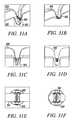
- FIGS. 1A and 1Bshow a side view and side-sectional view of a femur and tibia with an ACL graft secured to the bones using exemplary tendon anchor embodiments according to the present invention.
- FIG. 2shows a frontal view of a femur and tibia with an ACL graft secured to the bones using exemplary tendon anchor embodiments according to the present invention.
- FIGS. 3A to 3Dshow isometric and rear views of an exemplary direct tendon anchor embodiment according to the present invention.
- FIGS. 4A to 4Fshow isometric views, side sectional view, side view, rear view, and front view of an exemplary deployment system embodiment according to the present invention with an exemplary direct tendon anchor embodiment.
- FIGS. 5A and 5Bshow isometric views of the exemplary deployment system embodiment in FIGS. 4A to 4F with a dilator mechanism retracted to expand the direct tendon anchor.
- FIG. 6shows an isometric view of an exemplary direct tendon anchor embodiment according to the present invention.
- FIG. 7shows an isometric view of a substantially non-cylindrical direct tendon anchor according to the present invention.
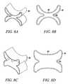
- FIGS. 8A and 8Bshow isometric and top view of a substantially non-cylindrical direct tendon anchor embodiment in an unexpanded orientation according to the present invention.
- FIGS. 8C and 8Dshow isometric and top view of the substantially non-cylindrical direct tendon anchor embodiment in FIGS. 8A and 8B in an expanded orientation.
- FIGS. 9A and 9Bshow side view and front view of the substantially non-cylindrical direct tendon anchor embodiment in FIGS. 8A to 8D securing an ACL graft to the femur.
- FIGS. 9C and 9Dshow a side view and front view of the substantially non-cylindrical direct tendon anchor embodiment in FIGS. 8A to 8D with an ACL graft positioned around the anchor.
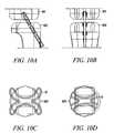
- FIGS. 10A to 10Dshow a side view, front view, and end views of the substantially non-cylindrical direct tendon anchor embodiments of FIGS. 8A to 8D securing an ACL graft to the femur and tibia.
- FIGS. 11A to 11Cshow side views of the steps for securing an ACL graft to the femur with an exemplary deployment instrument embodiment and a substantially non-cylindrical direct tendon anchor embodiment according to the present invention.
- FIGS. 12A to 12Dshow isometric view, side view, end view, and side-sectional view of the exemplary deployment instrument embodiment in FIGS. 11A to 11 C securing the substantially non-cylindrical direct tendon anchor embodiment in FIGS. 8A to 8D to the tibia.
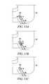
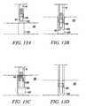
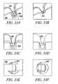
- FIGS. 13A to 13Dshow side views of the steps for securing a tendon to bone with an exemplary deployment instrument embodiment and a substantially non-cylindrical direct tendon anchor embodiment according to the present invention.
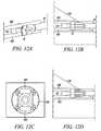
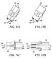
- FIGS. 14A to 14Dshow isometric views and side views of an alternative deployment instrument embodiment according to the present invention.
- FIGS. 15A to 15Dshow side views showing the steps for securing a tendon to bone with a substantially non-cylindrical direct tendon anchor and the deployment instrument in FIGS. 14A to 14D .
- FIGS. 16A to 16Dshow isometrics views, side view, and end view of a substantially non-cylindrical direct tendon anchor with another exemplary deployment instrument embodiment according to the present invention.
- FIG. 16Eshows an isometric view of the deployment instrument in FIGS. 16A to 16E with a tendon or graft engaged with the grasping mechanism.
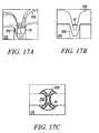
- FIGS. 17A to 17Cshow an isometric view, side-sectional view, and top view of the substantially non-cylindrical direct tendon anchor embodiment in FIGS. 8A to 8D securing a section of tendon to bone.
- FIGS. 18A to 18Dshow side view, isometric view, side-sectional view, and top view of the substantially non-cylindrical direct tendon anchor embodiment in FIGS. 8A to 8D securing the end of a tendon to bone.
- FIGS. 19A and 19Bshow isometric view and top view of an alternative substantially non-cylindrical direct tendon anchor embodiment in an unexpanded orientation.
- FIGS. 19C and 19Dshow isometric view and top view of the substantially non-cylindrical direct tendon anchor embodiment in FIGS. 19A and 19B in an expanded orientation.
- FIGS. 20A to 20Dshow isometric views and top view of two exemplary direct tendon anchor embodiments of the invention in an unexpanded orientation.
- FIGS. 20E & 20Fshow isometric view and top view of the direct tendon anchor embodiments in FIGS. 20A to 20D in an expanded orientation.
- FIGS. 21A to 21Dshow side-sectional view, and cross-sectional views of the direct tendon anchor embodiment in FIGS. 20A to 20F securing the strands of a tendon to bone.
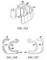
- FIGS. 22A and 22Bshow isometric views of a substantially non-cylindrical suture anchor embodiment according to the present invention.
- FIGS. 22C and 22Dshow isometric view and top view of an alternative substantially non-cylindrical suture anchor embodiment in an unexpanded orientation.
- FIGS. 22E and 22Fshow isometric view and top view of the substantially non-cylindrical suture anchor embodiment in FIGS. 22C and 22D in an expanded orientation.
- FIGS. 23A to 23Can show isometric view, bottom view and top view of an alternative substantially non-cylindrical direct tendon anchor embodiment according to the present invention.
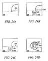
- FIGS. 24A to 24Dshow side views, side-sectional view, and top view of the substantially non-cylindrical direct tendon anchor embodiment in FIGS. 23A to 23D securing the end of a tendon to bone.
- FIGS. 25A to 25Fshow top views, isometric view, cross-sectional view, side view, and side-sectional view of the substantially non-cylindrical direct tendon anchor in FIGS. 23A to 23D securing a segment of tendon to bone.
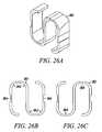
- FIGS. 26A to 26Cshow an isometric view, bottom view, and top view of an alternative direct tendon anchor embodiment of the invention.
- FIGS. 27A to 27Fshow isometric view, side view, isometric shaded view, side-sectional view, top view, and cross-sectional view of the direct tendon anchor embodiment in FIGS. 26A to 26D securing a segment of tendon to bone.
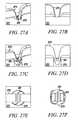
- FIGS. 28A and 28Bshow isometric view and side view of an alternative substantially non-cylindrical direct tendon anchor embodiment according to the present invention.
- FIGS. 28C and 28Dshow isometric view and side view of the substantially non-cylindrical direct tendon anchor embodiment in FIGS. 28A and 28B in an open orientation for grasping the tendon according to the present invention.
- FIGS. 28E & 28Fshow isometric view and side view of the substantially non-cylindrical direct tendon anchor embodiment in FIGS. 28A and 28B in a deployed orientation for securing the tendon to bone.
- FIGS. 30A to 30Cshow isometric view, top view, and side view of an alternative substantially non-cylindrical direct tendon anchor embodiment according to the present invention.
- FIGS. 30D to 30Fshow isometric view, top view, and side shaded view of the substantially non-cylindrical direct tendon anchor embodiment in FIGS. 30A and 30B in an expanded orientation.
- FIGS. 31A to 31Fshow isometric views, side view, side-sectional view, top view, and cross-sectional view of the substantially non-cylindrical direct anchor embodiment in FIGS. 30A to 30F securing a tendon to bone.
- FIGS. 32A to 32Cshow isometric view, side view, and top view of an alternative direct tendon anchor embodiment according to the present invention.
- FIGS. 33A to 33Fshow isometric views, side view, side-sectional view, top view, and cross-sectional view of the direct tendon anchor embodiment in FIGS. 32A to 32C securing a tendon to bone.
- FIGS. 34A to 34Dshow isometric view, top view, side view, and side-sectional view of an alternative substantially non-cylindrical direct tendon anchor embodiment securing the end of a tendon to bone.
- FIGS. 35A to 35Dshow isometric views, side view, and top view of an exemplary multiple component tendon anchor embodiment according to the present invention.
- FIGS. 36A and 36Bshow side view and top view of the multiple component tendon anchor embodiment in FIGS. 35A to 35D securing a tendon to bone.
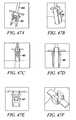
- FIGS. 37A to 37Dshow front view, isometric view, side view, and end view of an alternative multiple component tendon anchor embodiment and an exemplary deployment instrument embodiment according to the present invention.
- FIGS. 38A and 38Bshow side view and isometric view of the multiple component tendon anchor embodiment in FIGS. 37A to 37D positioning a tendon into a drilled bone hole.
- FIGS. 39A to 39Fshow isometric views, side view, and top view of a substantially non-cylindrical multiple component tendon anchor embodiment according to the present invention.
- FIGS. 40A to 40Fshow isometric views, side view, and top view of a substantially non-cylindrical multiple component tendon anchor embodiment according to the present invention.
- FIGS. 41A to 41Dshow isometric views, side view, and top view of a substantially non-cylindrical multiple component tendon anchor embodiment according to the present invention.
- FIGS. 42A to 42Dshow isometric views, side view, and top view of a substantially non-cylindrical multiple component tendon anchor embodiment according to the present invention.
- FIGS. 43A to 43Dshow isometric views, side view, and top view of a substantially non-cylindrical multiple component tendon anchor embodiment according to the present invention.
- FIGS. 44A to 44Dshow isometric views, side view, and top view of a substantially non-cylindrical multiple component tendon anchor embodiment according to the present invention.
- FIGS. 45A to 45Dshow side view of anchor delivery, inner wedge advancement and deployment of the substantially non-cylindrical tendon anchoring embodiment shown in FIGS. 44A to 44D .
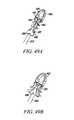
- FIGS. 46A to 46Dshow isometric views, side view, and top view of a substantially non-cylindrical multiple component tendon anchor embodiment according to the present invention.
- FIGS. 47A to 47Fshow side view of anchor delivery, inner wedge advancement and deployment of the substantially non-cylindrical tendon anchoring embodiment shown in FIGS. 46A to 46D .
- FIGS. 48A to 48Dshow isometric views, side view, and top view of a substantially non-cylindrical multiple component tendon anchor embodiment of the invention with two levels of expanding sections.
- FIGS. 49A and 49Bshow perspective views of a tendon anchor embodiment according to the present invention with pivoting arms and a wedge deployment mechanism disengaged and engaged with the anchor.
- FIG. 50shows an exemplary deployment mechanism used for the deployment of tendon anchor embodiment shown in FIGS. 49A and B.
- the present inventionrelates to devices, systems and methods that enable the direct fixation of tendons, and/or soft tissues to bone for the repair of torn or diseased tendons, or the reconstruction of unstable joints.
- the various embodimentsare applicable to surgical procedures that require direct fixation of tendon to bone. This includes a wide array of procedures including, but not limited to, the shoulder, elbow, wrist, hand, knee, ankle, and foot.
- the exemplary device embodiments of the inventionprovide a variety of bone anchors that allow fixation of tendon or other soft tissues directly to bone without requiring suture fixation of the tendon to the bone.
- Conventional bone anchorshave typically been tacks, which allow the pinning of adjacent tissues to bone; or suture anchors, which attach a suture to bone and the suture to the soft tissue to indirectly attach soft tissue to bone.
- the implant embodiments of the present inventionprovide direct attachment approaches that use the anchor itself (rather than attached sutures) to directly hold and stabilize the tendon or other soft tissue into bone tunnels or holes.
- Direct anchor embodimentsinclude uniquely shaped implants that hold a tendon or other soft tissue, and fix it directly to bone.
- the direct anchorcan, but does not always have to, be substantially non-cylindrical anchors having a non-circular cross-section, for example, bi-lobed (e.g., “butterfly” shaped), “clover-leaf” shaped, rectangular, and/or shaped with grooves or openings configured to differentially compress the tendon, or other soft tissue, directly against bone, and affix the anchor within the bone channel.
- the direct anchorcan incorporate expandable arms that compress the tendon or other soft tissue directly against bone while directly contacting the bone to provide anchoring of the implant.
- These direct anchor embodimentsmay be single or multi-component implants that allow for implant expansion by use of wedge elements. They can further include features such as grasping tines to prevent tendon (or other soft tissue) slippage during deployment and after attachment, and attachment tabs to prevent migration of the anchor from the bone hole or tunnel once positioned and secured in place.
- Some classes of anchorsare substantially symmetrical but have the characteristic of expanding wall portions or pivoting arms that aid in the press fit of the anchor within a hole in a bone. These anchors also typically have tabs or other gripping portions that serve to lock the anchor in place within the bone hole.
- direct anchor embodimentscan incorporate “docking slots” which allow sutures to augment or replace the direct attachment of the tendon, or other soft tissue, to bone.
- These direct anchor embodimentscan also incorporate groves to secure and align the tendon along the implant prior and during implant deployment. This alignment feature minimizes or prevents the tendon from interfering with the anchor to bone contact needed for optimal anchoring of the implant.
- the insertion of the direct anchormay be standardized with the use of a corresponding equipment tray.
- the initial procedural stepmay involve the use of a guide pin which allows the accurate localization and directionality of the bone hole, through which the tendon, or other soft tissue, is inserted and secured with the direct anchor.
- a cannulated drillof appropriate size can be used to create a drill hole over the guide pin.
- the drillhas a depth stop to allow accurate depth for the anchor.
- the traycan hold a variety of drill sizes ranging from 3 mm to 12 mm in diameter.
- the traymay have a device used to determine the diameter of the tendon that will be directly secured to the bone within the drilled hole.
- the exemplary methods and devices described hereinstandard surgical preparation of the site and/or arthroscopic portals for access of the region are performed.
- the jointis dilated with arthroscopic fluid if the procedure is to be performed arthroscopically.
- the deviceWith open procedures, the device may easily be manipulated and deployed with a single hand.
- the deployment deviceis introduced through a standard 5, 6 or 8 mm cannula placed into the joint. A range of cannula sizes would be 2-11 mm.
- the direct anchor devices as described in the present inventionmay be used with a variety of techniques.
- the specific details of the techniquewill vary depending on the anatomic structure being repaired and the device embodiments of the invention.
- An example of four specific useswill be described to demonstrate the versatility of the present implant embodiments according to the present invention.
- the techniquesrelate to classes of procedures rather than individual procedures. They are generally described here and will be presented in more detail below:
- Double tendon strand techniqueThis technique is used when the available tendon is abundant, or when a tendon requires fixation at its mid-point;
- Rotator cuff repair techniqueThis technique uses the shape of the implant to act as a pulley to draw the rotator cuff margin into a bone tunnel.
- the tenodesis of some tendonsis limited by the length of the tendon. Repair of the distal biceps of the elbow is an example of this type of procedure. In this situation, the tendon may not be long enough to achieve two-point compression between the deployed anchor and the tendon. Two-point compression is achieved by other techniques using the embodiments of the present invention, as described below, by looping the tendon around the anchor such that two segments of tendon are engaged by the direct anchor and compressed directly against bone tissue.
- the repaircan be reinforced by suturing the tendon to the anchor prior to or after insertion. This serves to minimize tendon slippage during insertion, and provides a second point of fixation after anchor deployment.
- the procedurestarts with preparation of the tenodesis site, which is initially prepared by dissecting the soft tissues from the region. This can be done with an open technique or arthroscopically depending on the procedure performed. A guide pin is then placed into the bone to the depth and direction desired for the bone tunnel. A cannulated drill is drilled over the top of the guide pin to create the tenodesis hole.
- the next stepinvolves exposing the tendon end that is in need of repair.
- a non-absorbable grasping stitchis placed at the end of the tendon, which can be used for traction and repair.
- the tendonis traditionally prepared with an open or limited open exposure, but can be prepared arthroscopically in some instances.
- the grasping sutureis then applied to the lateral margins of the anchor, seating them firmly into the “docking” slots. With the tendon pulled tight against the anchor, the tendon is wrapped around the tip of the anchor where grasping tines help prevent slippage.
- the sutureis then tied over the top of the tendon body, creating two points of fixation onto the anchor.
- the tendonmay be inserted into the pre-drilled bone hole.
- the tendon-anchor assemblywill fit snugly into the hole and should be inserted to the level of the stop placed on the anchor deployment device.
- the anchoris deployed by squeezing the hand-held trigger mechanism.
- Anchor deploymentresults in compression of the anchor against the surrounding bone, and also compresses the tendon against the bone.
- the deployment instrumentis simultaneously released from the anchor, leaving only the tendon-anchor construct firmly attached to bone.
- a trailing suturecan be attached to the anchor and be used to reinforce the repair if needed.
- Two tendon armscan be fixed simultaneously by using an implant that straddles and supports the tendon into its bone tunnel. This technique can be used in most scenarios that would traditionally use a bone bridge to fix the tendon into position.
- This type of fixationinclude the distal fixation for elbow collateral ligament reconstructions, proximal fixation of hamstring reconstructions, and the fixation of the long head of the biceps tendon in the shoulder.
- tendon to bone compressionoccurs on two surfaces simultaneously, direct tendon compression to bone is sufficient to prevent tendon slippage during insertion. As a result, the tendon does not need to be sutured to the anchor prior to or after insertion.
- the procedurestarts with preparation of the tenodesis site, which is initially prepared by dissecting the soft tissues from the region. This can be done with an open technique or arthroscopically, depending on the procedure performed.
- a guide pinis placed into the bone to the depth and direction desired for the bone tunnel.
- a cannulated drillis drilled over the top of the guide pin to create the tenodesis hole.
- the end of the tendondoes not need to be prepared, though some type of traction suture may be placed to facilitate tensioning and positioning of the tendon.
- the anchorWith the tendon positioned and tensioned over the bone hole, the anchor is placed over the top of the tendon. The arms at the tip of the anchor then straddle the tendon, supporting it as it is pushed into the bone tunnel. The tendon-anchor-tendon assembly fits snugly into the hole and should be inserted to the level of the stop placed on the anchor deployment device.
- the anchorOnce seated, the anchor is deployed by actuating a hand-held trigger mechanism. Anchor deployment results in compression of the anchor against the surrounding bone, and direct compression of the two tendon strands against bone. Once deployed, the deployment instrument is simultaneously released from the anchor, leaving only the tendon-anchor-tendon construct firmly attached to bone. A trailing suture attached to the anchor can be used to reinforce the repair if needed.
- Some surgical proceduresrequire the fixation of tendon strands within and/or as they extend from a bone tunnel.
- the tendonshave been placed from the opposite side and need fixation from a different direction.
- a modified anchorsliding anchor
- Examples where this type of fixation is neededare the tibial fixation of hamstring anterior cruciate ligament reconstructions and the humeral fixation of elbow collateral ligament reconstructions.
- the sliding anchoris similar to the standard tenodesis anchor except that it does not expose grasping tines, which prevent the anchor from sliding, during insertion. These anchor embodiments need to slide between the tendon, or graft, strands into a position that is desired before deployment.
- the bone tunnelhas already been created and the tendon strand(s) are already either seated into the tunnel, or are protruding from the tunnel. Traction is pulled on the tendon arms, either with direct pull or via traction sutures placed at the tendon end.
- the free anchoris then positioned to slide between the tendon arms into its desired position. At times, this is at the most external position in the tunnel, and at other times advanced deep into the tunnel.
- the anchoris deployed manually by actuating the single-hand trigger mechanism of a deployment instrument. As the anchor is deployed it is expelled from the deployment instrument, leaving the deployed direct anchor implant behind. The result is an anchor providing direct lateral compression of the tendon strands into the bony tunnel.
- a trailing suture attached to the anchorcan be used to reinforce the repair if needed.
- the repair of rotator cuff tearscan be performed utilizing the unique shape of this implant. Repairing a rotator cuff tear into a trough is a technique often used during open procedures but difficult to perform arthroscopically. The shape of this anchor facilitates rotator cuff repair into a trough utilizing a sliding suture technique.
- the greater tuberosityis debrided with a mechanical shaver down to bone.
- a round burris then used to create a bone trough in the tuberosity in an area that allows the cuff tissue to be repaired with minimal tension.
- a drill holeis placed in the depth of the trough at its lateral margin.
- a mattress sutureis then passed into the lateral margin of the rotator cuff with the suture strands exiting superiorly.
- suturesare then pulled out the lateral portal and threaded through tunnels in the anchor.
- the anchorWith traction placed on the rotator cuff stitch, the anchor is inserted into the joint and positioned adjacent to the rotator cuff margin. With various amounts of traction, the anchor is pushed into the drill hole, pulling the cuff margin into the trough. With the correct amount of traction, the rotator cuff margin is pulled into the trough just above the anchor. The anchor is then deployed and the sutures wedged into the anchor, creating a knotless rotator cuff repair.
- This techniqueutilizes the anchor to grasp the suture and fix it to bone, eliminating the need for arthroscopic knot tying.
- the primary strength of the repairis related to the anchor grasping the suture. The most difficult step in fixation is then made knotless.
- the tenodesis anchorcan be used for other indications involving the fixation of soft tissue to bone.
- the embodiments of this invention as presented herein and in the figuresare tailored to human anatomy. Additionally, the present invention may also be tailored for use in other species such as horses, dogs, sheep, and pigs as well as invertebrates.
- One having ordinary skill in the artcould reconform the exemplary embodiments described herein without undue experimentation to fit or be suitable for animals other than humans. Such new configurations for use in non-human subjects are also within the scope and spirit of the present invention.
- the size and scope of the invention describedprovides additional advantages that include, but are not limited to: providing an arthroscopic approach for the tenodesis of tendons; reduction in the visible scars associated with open surgical procedures by using small port access allowed by the deployment device; reducing the complexity associated with arthroscopic knot tying; and reducing the required surgical time as well as the level of complexity associated with these procedures.
- the use of devices according to the present inventionmay be applied to virtually all orthopedic procedures requiring fixation of tendon, or other soft tissue, to bone.
- the inventionis useful for procedures whether performed with open dissection or with arthroscopic techniques.
- Non-limiting examplesinclude, but are not limited to: (a) shoulder (rotator cuff repair, long head of biceps tenodesis); (b) elbow (distal biceps tendon repairs, medial (ulnar) collateral ligament reconstruction—the “Tommy John Procedure”, lateral ulnar collateral ligament reconstruction—for posterolateral rotatory instability of the elbow); (c) wrist (carpal instability—scapholunate and lunotriquetral ligament reconstructions, Blatt Capsulodesis, thumb carpometacarpal arthroplasty (ligament reconstruction with tendon interposition—LRTI)); (d) hand (chronic thumb ulnar collateral ligament reconstruction (Gamekeeper's thumb), chronic thumb radial collateral ligament reconstruction, finger metacarpophalangeal ligament reconstruction); (
- FIGS. 1A and 1Bshow a side view and a side-sectional view of a hamstring anterior cruciate ligament (ACL) reconstruction with exemplary direct tendon anchor embodiments used to secure the ACL graft proximal to the femur 11 and distal to the tibia 12 .
- FIG. 2shows a front view of the ACL reconstruction shown in FIGS. 1A and 1B .
- one exemplary direct tendon anchor 17is used to secure the wrapped two strand hamstring graft 13 to the femur 11 by inserting the anchor through a drilled bone hole 18 created completely through the tibia 12 and partially through the femur 11 .
- Three direct tendon anchors 15are shown to secure the free ends of the hamstring graft strands 13 to the tibia 12 . It should be noted than any number of direct tendon anchors ( 1 to 5 ) can be utilized to secure the graft within the drilled bone hole.
- FIGS. 3A to 3Dshow an isometric view, an end view, a shaded isometric view, and an isometric view, respectively, from the opposing end for one exemplary direct tendon anchor device 31 embodiment of the invention.
- This direct anchor embodiment 31can be utilized to separately secure all discrete four strand ends of the hamstring ACL graft within a bone.
- the exemplary direct anchor embodiment 31can be utilized to secure two strand tendons or single strand tendons, or grafts, within a drilled bone hole.
- one end 32 of the exemplary direct anchor embodimentis flared at the “clover leaf” extensions to partially penetrate into bone and increase the surface area of the contacting segment between the direct anchor embodiment and the surface of the bone defined by the drilled hole.
- the mid-section 33 between these “clover leaf” extensionsare not flared to ensure the direct anchor is able to expand into a radially enlarged orientation during deployment, ensuring the direct anchor compresses the tendon against the bone surface defined by the drilled hole.
- the opposite end of the direct anchor embodiment 31can incorporate an inward radius 36 to increase the surface area of contact between the tendon and direct anchor 31 , and provide an atraumatic surface between the direct anchor 31 and tendon strands that loop around this end 35 of the direct anchor 31 .
- This anchor embodiment 31can be used to secure the proximal, looping end of the hamstring ACL graft within the femoral drilled bone hole or other sliding anchor applications where a tendon or graft is looped around the anchor.
- this anchor embodiment 31can be used to secure tendon or grafts within drilled bone holes using the double tendon strand technique, as described above. During the double tendon strand technique, the tendon strand loops around this end of the direct tendon anchor wherein the radiused end 35 prevents damage to the tendon or graft caused by contact with the direct anchor 31 .
- FIG. 4Ashows an isometric view of an exemplary deployment instrument 41 according to the present invention.
- FIGS. 4B to 4Fshow an isometric view, a side-sectional view, a side view, a rear end view, and a front view, respectively, of the exemplary deployment instrument in FIG. 4A with a direct anchor 42 supported for deployment.
- This exemplary deployment instrument 41includes a movable anvil 43 that incorporates a transition from the pull rod 44 to the distal expanding dilator 45 .
- the distal end of the dilatorcontains a radius 46 to prevent trauma to the tendon as the instrument 41 positions the direct anchor 42 and secures the tendon within the drilled bone hole while expanding the direct anchor 42 .
- the deployment instrument 41incorporates a holding shaft 47 to support the direct anchor 42 while the dilator 45 is actuated thereby expanding the direct anchor 42 into an enlarged orientation.
- the holding shaft 47incorporates protrusions 48 that fit inside the “clover leaf” extensions of the direct anchor 42 .
- FIGS. 5A and 5Bshow the exemplary deployment instrument 41 in FIGS. 4A to 4F with the dilator 45 retracted.
- FIG. 5Bshows a four strand tendon graft 51 (commonly used during the hamstring ACL reconstruction) positioned with each strand 51 held within a groove 49 of the direct anchor 41 .
- two strands or a single strand looped or with one end freecan be supported within the grooves 49 of the direct anchor 41 .
- the innermost grooves 49 of the direct anchor 41are deformed outwardly thereby compressing the tendons 51 supported within the grooves 49 against the surface defined by the drilled bone hole.
- the “clover leaf” extensionsare further expanded outward into engagement with the bone thereby securing the direct anchor 41 thus the supported tendon within the drilled bone hole.
- FIG. 6shows an alternative direct anchor embodiment 61 where one end 62 of the direct anchor is flared throughout one edge.
- the opposite end 63 of the direct anchor 61is straight.
- the flared end 62can be flared along the entire periphery of the direct anchor 61 , as shown; or it could be flared only at the “clover leaf” extensions as shown in FIGS. 3A to 3C with the mid region defined by the grooves straight to facilitate expansion of the direct anchor.
- the direct anchor embodiment 61is expanded into an enlarged orientation, the tendon is compressed against the bone-drilled surface and the “clover leaf” extensions are pressed into the surface of the bone defined by the drilled bone hole.
- the flared end 62increases the bond strength between the direct anchor 61 and the bone surface by increasing the surface area of contact between the bone and the anchor 61 and ensuring any tension applied to the bone anchor 61 is distributed over a large surface that deflects the applied forces in a non-axial direction to increase contact upon further deflection of the bone anchor.
- FIG. 7shows an isometric view of a substantially non-cylindrical direct anchor embodiment 71 designed to secure a single strand looped around the direct anchor 71 , two strands looped around the direct anchor 71 , or one or two tendon free ends to the surface defined by the drilled bone hole.
- This direct anchor embodiment 71incorporates an inward radius along one end 72 to prevent trauma to looping tendon, or graft, segments.
- this anchor embodiment 71enables the change of applied forces that compress the graft (e.g., tendon) against bone tissue versus the forces that the anchor 71 applies against the bone tissue required to ensure the pull-out forces are high enough that the anchor 71 , thus the compressed graft, will not dislodge from the bone channel.
- These variable forcesprevent abrading, tearing, or otherwise damaging the graft while deploying the anchor 71 or supporting the graft once the anchor 71 is affixed within the bone channel.
- FIGS. 8A and 8Bshow an isometric view and a top view of another substantially non-cylindrical direct anchor embodiment 81 of the present invention.
- FIGS. 8C and 8Dshow an isometric view and a top view of the direct anchor embodiment 81 shown in FIGS. 8A and 8B in an expanded orientation.
- the inner grooves 82 and 83 of the direct anchor 81are expanded radially thereby causing the “butterfly” extensions to deform radially outward into engagement with the bone surface defined by the drilled hole.
- FIGS. 9A and 9Bshow a side and front view of a femur 91 with two strands 92 of a hamstring ACL graft looped around the exemplary substantially non-cylindrical direct anchor 71 of FIG. 7 .
- the substantially non-cylindrical direct anchor embodiment of FIG. 7can be used to connect any looping (or free end) tendon or graft to the bone surface defined by the drilled hole 94 .
- FIGS. 10A to 10Dshow a side view, a front view, an end view, and a cross-sectional view of the substantially non-cylindrical direct anchors in FIGS. 7 and/or 8 used to secure an ACL graft at the femoral end 101 and the tibial end 102 .
- the “butterfly” extensions of the direct anchor 71are deflected into the surface 103 of the bone defined by the drilled hole to ensure engagement between the direct anchor 71 and the bone 101 or 102 as the direct anchor 71 is expanded with the deployment instrument 41 .
- FIGS. 11A to 11Cshow side-sectional views of exemplary steps that may be taken in positioning and securing an ACL graft 113 within a hole 112 drilled into the femur 111 using substantially non-cylindrical direct anchor embodiments 71 or 81 shown in FIGS. 7 and 8 .
- the ACL graft strands 113are looped around the distal end of the direct anchor 71 and inserted through the bone hole 112 of the femur 111 .
- the dilator 45is actuated to expand the direct anchor 71 into the drilled bone hole 112 .
- the direct bone anchor 71compresses the tendon 113 against the surface of the femur 111 defined by the drilled hole 112 and engages the securing extensions of the direct anchor 71 against the bone surface to ensure the tendon 113 is secured in place as tension is applied.
- FIGS. 12A to 12Dshow an isometric view, a side view, a cross-sectional view, and a side-sectional view of the deployment instrument 41 in FIG. 4A with the substantially non-cylindrical direct anchor embodiment 71 of FIGS. 7 and 8 positioned for placement.
- the deployment instrument 41is positioned between the strands 122 of the ACL graft free ends to secure the ACL graft 122 to the tibia 121 .
- the dilator 45is actuated thereby expanding the direct anchor 71 inside the drilled bone hole 123 , compressing the tendon free ends 122 against the bone surface defined by the drilled hole 123 and engaging the securing extensions of the direct anchor 71 against the bone 121 .
- FIGS. 13A to 13Dshow exemplary steps for deploying and attaching a strand of tendon or graft within a drilled bone hole.
- the deployment instrument 41 of FIG. 4Ais used to insert the looping strand 132 of tendon and the direct anchor 139 into a pre-drilled bone hole 133 in a bone 131 .
- the dilator 45is actuated, expanding the direct anchor 139 into engagement with the bone surface defined by the drilled hole 133 and compressing the tendon 132 against the bone.
- the deployment instrument 41is removed, as shown in FIG. 13C , leaving the tendon 132 , or graft, secured within the bone hole 133 via the direct anchor 139 , as shown in FIG. 13D .
- FIGS. 14A to 14Dshow two isometric views, a side view, and a side-sectional view, respectively, of an alternative deployment instrument embodiment 141 according to the present invention.
- This deployment instrument 141uses an anvil 142 to support the direct anchor 143 while a shaft 144 incorporating an expansion transition is actuated and advanced relative to the direct anchor 143 .
- the expansion shaft 144is used to expand the direct anchor 143 into a radially enlarged orientation.
- the anvil 142releases from the central lumen of the direct anchor 143 signaling full expansion of the direct anchor 143 thus completing attachment of the tendon(s) to the surface of the bone defined by the drilled hole.
- the anvil 142supports the direct anchor 143 as the expansion shaft 144 continues to move axially further expanding the direct anchor 143 .
- This exemplary deployment instrument embodiment 141further incorporates a tendon positioner 145 that aids in placement of the tendon into the bone hole.
- this positioner 145is a needle tip that punctures into the tendon and holds the tendon while it and the direct anchor 143 are placed into the bone hole.
- the anvil 142may incorporate a central lumen through which a clamp or snare can be manipulated to grasp the tendon.
- two opposing metal clamping ribbonsare spring loaded to engage and compress around the tendon while grasping the tendon for placement.
- a single wire or ribbonis looped outside the central lumen. As the snare is advanced, the loop opens and as the snare is retracted, the loop compresses against the tendon placed within the snare opening. Once secured, the grasping mechanism is release from the tendon and removed from the bone hole.
- FIGS. 15A to 15Dshow the exemplary deployment instrument 141 in FIGS. 14A to 14D used to place a segment of tendon 153 into a bone hole 152 and secure it by expanding the direct anchor 143 thereby engaging the anchor 143 to the surface of the bone 151 defined by the drilled hole 152 and compressing the tendon 153 against this surface to promote healing of the tendon 153 to the bone 151 .
- FIGS. 16A to 16Dshow isometric views, a side view, and an end view, respectively, of the deployment instrument 141 in FIGS. 14A to 14D with the needle tip tendon engagement mechanism modified to a two ribbon wire 146 and 147 clamping mechanism.
- the spring-loaded clamping mechanism 146 and 147As the spring-loaded clamping mechanism 146 and 147 is advanced beyond the central lumen of the anvil 142 it expands into an enlarged opening between the two distal ends of the clamping mechanism 146 and 147 .
- the clamping mechanism 146 and 147is placed over a tendon 145 or graft, as shown in FIG. 16E , the clamping mechanism 146 and 147 is retracted thereby clamping the tendon 145 and engaging it to enable positioning the clamp 146 and 147 along with the supported direct anchor 143 into the drilled bone hole for attachment.
- FIGS. 17A to 17Cshow an isometric view, a side-sectional view, and a top view, respectively, of the substantially non-cylindrical direct anchor embodiment 71 in FIGS. 7 and 8 securing a segment of tendon 173 within a bone hole 172 of a bone 171 .
- the tendon segment 173loops around the distal end of the substantially non-cylindrical direct anchor 71 and fits within the opposing grooves.
- the groovesare deflected outward compressing the tendon 173 against the surface of the bone 171 defined by the drilled hole 172 , and engaging the butterfly extensions of the direct anchor 71 to the bone surface thereby attaching the tendon 173 within the bone hole 172 .
- FIGS. 18A to 18Dshow a side view, an isometric view, a side-sectional view, and a top view, respectively, of the substantially non-cylindrical direct anchor embodiment 71 shown in FIGS. 7 and 8 securing the free end of a tendon 183 , or graft, within a bone hole 182 of a bone 181 .
- the deployment instrument described aboveincorporates a grasping mechanism to grasp the free end of the tendon 183 and place the free end into the bone hole 182 such that the tendon 183 passes along one of the grooves in the direct anchor 71 .
- the direct anchor 71is expanded into the bone hole 182 to compress the tendon 183 against the surface of the bone 181 defined by the drilled hole and engage this surface with the extensions of the direct anchor.
- FIGS. 19A and 19Bshow an isometric and a top view of an alternative substantially non-cylindrical direct anchor embodiment 191 that incorporates “butterfly” extensions 192 that engage the surface of the bone defined by the drilled hole, and slots 193 that create flaps 194 that, once positioned and actuated, engage either the tendon and/or the surface of the bone defined by the drilled hole to increase the bond strength between the substantially non-cylindrical direct anchor 191 and the tendon to the bone.
- FIGS. 19C and 19Dshow an isometric view and a top view of the substantially non-cylindrical direct anchor embodiment 191 in FIGS. 19A and 19B in an expanded orientation with the substantially non-cylindrical direct anchor 191 fully deformed to compress tendon against the surface of the bone defined by the drilled hole and engage the bone anchor to that surface.
- FIGS. 20A and 20Bshow isometric views of two alternative direct anchor embodiments 201 and 205 that incorporate a “clover leaf” proximal end 202 transitioning to a cone distal end 203 .
- the embodiment of FIG. 20Afurther incorporates loops 204 that are either connected to the distal end 203 or pass through the central lumen where they connect to another component of the anchor 201 or are incorporated as one or more snares to the deployment instrument, previously described.
- FIGS. 20C and 20Dshow an isometric view and a top view of the direct anchor embodiment 205 of FIG. 20B in an unexpanded orientation.
- FIGS. 20E and 20Fshow an isometric view and a top view of the direct anchor embodiment 205 in FIGS. 20B to 20D in an expanded orientation.
- the proximal end 202 of the embodiment in FIG. 20Awould expand similar to that for the embodiment shown in FIGS. 20E and 20F .
- the inner grooves 208are deflected outward whereby they partially straighten into a larger radius of curvature, as shown in FIGS. 20D and 20F .
- the “clover leaf” extensions 209are radially expanded into engagement with the surface of the bone defined by the drilled hold. These extensions 209 also open up while the direct anchor 205 is deployed, however their preshaped radii of curvature are less than that for the grooves 208 ; therefore, any expansion of the direct anchor 205 straightens the grooves 208 before the extensions 209 open up. That way, the extensions 209 maintain their ability to engage the bone surface defined by the drilled hole.
- FIGS. 21A to 21Dshow a side-sectional view, a cross-sectional view oriented away from the bone axis, a cross-sectional view oriented towards the bone axis, and a top view, respectively, of the direct anchor 205 in FIG. 20B to 20F with four strands 213 of tendon supported by the grooves 208 of the direct anchor 205 .
- the four strand 213 engagementis common with the hamstring ACL reconstruction at a bone hole 212 in the tibial 211 attachment side.
- this direct anchor embodiment 205may alternatively be used to secure one or two strands of tendon 213 , or graft during double tendon strand or sliding anchor techniques.
- FIGS. 22A and 22B , and 22 C and 22 Dshow two substantially non-cylindrical direct anchor embodiments 221 capable of being used during double tendon strand or sliding anchor techniques described above, as well as rotator cuff repair and suturing the tendon to the implant techniques.
- This substantially non-cylindrical direct anchor embodiment 221incorporates offset openings 222 through which one or more suture strands can be inserted.
- the sutureis secured to the direct anchor 221 as the openings 222 are deformed closed locking the suture in place.
- the grooves 223are expanded outward thereby compressing any tendon positioned along the groove 222 against the surface of the bone defined by the drilled hole.
- the “butterfly” extensions 224are expanded radially outward into engagement with this bone surface thereby securing the direct anchor 221 to the bone.
- FIGS. 23A to 23Cshow an isometric view, a bottom view and a top view, respectively, of an alternative substantially non-cylindrical direct anchor embodiment 231 according to the present invention.
- the substantially non-cylindrical direct anchor 231incorporates a flex region 232 along which the substantially non-cylindrical direct anchor 231 (in this case fabricated from a resilient elastic member) can be compressed into a small diameter for insertion into the bone. Once positioned, this direct anchor 231 is released to expand towards its preformed configuration where it locks to the bone surface defined by the drilled hole and compresses the tendon against that surface.
- the substantially non-cylindrical direct anchor 231may alternatively be deformable and manually expanded, via actuation with a deployment clamp, into an enlarged, deformed orientation whereby the direct anchor 231 engages the bone surface.
- Two notches 233are incorporated in the direct anchor 231 for a clamp to temporarily engage the direct anchor 231 and enable manipulating the direct anchor 231 into a compressed or enlarged orientation.
- the cross-section of the direct anchor 231resembles the cross-section of a cone such that the proximal wider edge can engage the surface of the bone defined by the drilled hole along the periphery of the direct anchor.
- FIGS. 24A to 24Dshow two side views, a side-sectional view, and a top view, respectively, of the substantially non-cylindrical direct anchor embodiment 231 in FIGS. 23A to 23C securing the free end of a tendon 243 , or graft, within a bone hole 242 of a bone 241 .
- This embodiment 231enables clamping the tendon 243 , or graft, in the central opening 238 defined by the “C” link and the outer link of the integrated direct anchor 231 .
- the clamp deployment mechanismis used to enlarge this central opening 238 for positioning around the free end of the tendon 243 such that once positioned, the clamp is relaxed compressing the tendon 243 between the opposing links thereby engaging the tendon 243 to the direct anchor 231 for placement.
- the tendon 243is positioned within the lumen 238 of the “C” link such that it can be compressed against the bone surface defined by the drilled hole 242 once deployed.
- FIGS. 25A to 25Fshow two top views, an isometric view, a cross-sectional view, a side view, and a side-sectional view, respectively, of the substantially non-cylindrical direct anchor embodiment 231 in FIGS. 23A to 23D securing an in-line segment of tendon 253 within a bone hole 252 of a bone 251 .
- this substantially non-cylindrical direct anchor embodiment 231is enlarged to engage a segment of tendon 253 such that the tendon 253 loops around the distal end of the direct anchor 231 .
- the substantially non-cylindrical direct anchor 231is compressed into a small diameter for positioning into a bone hole 252 .
- the substantially non-cylindrical direct anchor 231is released or manually enlarged to secure the substantially non-cylindrical direct anchor 231 to the surface of the bone 251 defined by the drilled hole 252 and compress the tendon 253 against that surface.
- FIGS. 26A to 26Cshow an isometric view, a bottom view, and a top view, respectively, of an alternative direct anchor embodiment 261 .
- This embodimentalso incorporates flex regions 262 along which the direct anchor 261 can be compressed or enlarged.
- the direct anchor 261incorporates openings 263 through which tendon can be engaged during actuation of the direct anchor 261 .
- opposing notches 264 along the outer “S” linksare configured for a clamp to engage the “S” direct anchor 261 for compressing or expanding the direct anchor 261 .
- FIGS. 27A to 27Fshow an isometric view, a side view, a shaded isometric view, a side-sectional view, a top view, a cross-sectional view, respectively, of the direct anchor embodiment 261 shown in FIGS. 26A to 26C with a tendon 273 looped around the distal link of the “S” direct anchor 261 positioned in a bone hole 272 of a bone 271 .
- FIGS. 28A and 28Bshow an isometric view and a side view of another exemplary substantially non-cylindrical direct anchor embodiment 281 that may also function as a clamp.
- This substantially non-cylindrical direct anchor embodiment 281incorporates opposing engagement ears 282 through which a deployment actuator can engage the base of the direct anchor 281 for manipulation.
- clamp legs 283are incorporated in the substantially non-cylindrical direct anchor 281 for engaging the tendon.
- This substantially non-cylindrical direct anchor 281further incorporates a central flex region along which the base 284 of the direct anchor 281 can be compressed or expanded, thereby expanding or compressing the clamp legs 283 .
- FIGS. 28C and 28Dshow the substantially non-cylindrical direct anchor embodiment 281 in FIGS. 28A and 28B in a compressed orientation where the base is actuated into a compressed orientation such that the clamp legs 283 enlarge for grasping a tendon.
- the base 284is expanded, as shown in FIGS. 28E and 28F .
- the direct anchor 281increases compression of the tendon securing the tendon to the direct anchor 281 and the base 284 expands into engagement with the surface of the bone defined by the drilled hole.
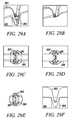
- FIGS. 29A to 29Fshow two isometric views, two top views, a cross-sectional view, and a side-sectional view, respectively, of the substantially non-cylindrical direct anchor embodiment 281 in FIGS. 28A to 28F securing a segment of tendon 293 , or graft, within a bone hole 292 of a bone 291 .
- FIGS. 30A to 30Cshow an isometric view, a top view, and a side view, respectively, of an alternative substantially non-cylindrical direct anchor embodiment 301 according to the present invention.
- This substantially non-cylindrical direct anchor 301incorporates a central opening 302 through which a dilation mechanism can be advanced to expand the direct anchor 301 into engagement with the surface of the bone defined by the drilled hole.
- Tabs 303 and 304are also included in the direct anchor 301 to ensure attachment of the tendon to the anchor 301 and the anchor 301 to the bone hole.
- the central tabs 303prevent movement of the tendon relative to the substantially non-cylindrical direct anchor 301 once positioned and expanded into engagement.
- the reverse tabs 304prevent dislodgement of the substantially non-cylindrical direct anchor 301 from the bone hole once positioned and secured.
- Clamp legs 308define an opening into which the tendon can be placed and supported during positioning of the tendon and direct anchor into the bone hole.
- Grooves 309provide openings into which tendon strands can be placed and compressed against the surface of the bone defined by the drilled hole once the substantially non-cylindrical direct anchor 301 is expanded with the deployment instrument.
- FIGS. 30D to 30Fshow an isometric view, a top view, and a side view, respectively, of the embodiment shown in FIGS. 30A to 30C in an expanded orientation.
- FIGS. 31A to 31Fshow two isometric views, a side view, a side-sectional view, a top view, and a cross-sectional view, respectively, of the substantially non-cylindrical direct anchor embodiment 301 shown in FIGS. 30A to 30F securing a segment of tendon 313 within a bone hole 312 of a bone 311 .
- FIGS. 32A to 32Cshow an isometric view, a side view, and a top view of another exemplary direct anchor embodiment 321 for securing a segment of tendon within a bone hole.
- Tabs 322 extending from the direct anchor 321engage the surface of the bone defined by the drilled hole to secure the tendon and the direct anchor 321 within the bone hole.
- FIGS. 33A to 33Fshow two isometric views, a side view, a side-sectional view, a top view, and a cross-sectional view, respectively, of the direct anchor 321 shown in FIGS. 32A to 32C securing a segment of tendon 333 within a bone hole 332 of a bone 331 .
- FIGS. 34A to 34Dshow an isometric view, a top view, a side view, and a side-sectional view of another substantially non-cylindrical direct anchor 341 securing a free end of tendon 343 within a bone hole 342 of a bone 341 .
- FIGS. 35A to 35Dshow two isometric views, a side view, and a top view of an exemplary multiple component direct anchor embodiment 351 according to the present invention.
- This multiple component direct anchor 351incorporates a central tip 352 around which the tendon loops and a proximal, radially expanding base 353 that expands as tension is applied to the central tip 352 thereby further expanding into engagement with the surface of bone defined by the drilled hole. Therefore, as tension is applied to the tendon, the central tip 352 is retracted thereby enlarging the diameter of the proximal base 353 which further engages the bone surface ensuring the tendon does not pull free from the bone hole.
- the proximal base 353can consist of two mating pieces that are free moving, slide radially relative to each other, are hinged at one end with the other free to move so the base can radially expand, or otherwise define a radially expansion mechanism that enlarges in diameter as the central tip is retracted.
- FIGS. 36A and 36Bshow a side view and a top view of the direct anchor embodiment 351 shown in FIGS. 35A to 35D securing a segment of tendon 363 within a bone hole 362 of a bone 361 .
- the tendon 363loops inside the proximal base 353 and around the central tip 352 thereby securing the tendon 363 to the direct anchor 351 and ensuring that any tension on the tendon 363 causes the proximal base 353 to enlarge thus increasing the engagement of the direct anchor 351 to the bone 361 and ensuring integrity of the bone 361 to anchor 353 to tendon 363 bond.
- FIGS. 37A to 37Dshow a front view, an isometric view, a side view, and an end view of an alternative multiple component direct anchor embodiment 371 with a deployment instrument 375 .
- the tendonloops around the central tip after passing within the lumen of the base.
- the deployment instrument 375engages the proximal base and defines space along which the tendon can pass.
- FIGS. 38A and 38Bshow a side view and an isometric view of the deployment of the direct anchor embodiment 371 in FIGS. 37A to 37D .
- the deployment instrument 375is used to position the tendon 383 and direct anchor 371 , in an unstressed low profile orientation, into the bone hole 382 .
- tensionis applied either to the central tip 372 or to the tendon 383 thereby enlarging the proximal base 373 into engagement with the surface of the bone 381 defined by the drilled hole 382 .
- the proximal base 373secures the direct anchor 371 and the attached tendon 383 within the bone hole 382 such that any additional tension applied to the tendon 383 increases the engagement between the multiple component direct anchor 371 and the bone 381 .
- FIGS. 39A to 39Fshow isometric views, side view, and top view of an exemplary substantially non-cylindrical, multiple component tendon anchor embodiment 391 according to the present invention.
- the outer anchor component's four side walls (arms) 393can be deflected both inward and outward during deployment. Inward deflection may be allowed to make advancement of the device 391 into the bone hole easier, while outward deflection will anchor the implant 391 to the bone.
- the center arms 394are in direct contact with a tendon which is aligned and looped around the distal end of the implant 391 .
- the flattened or curvilinear shape of the center arms 394is designed to optimize the implant to tendon contact area, which in turn increases the tendon to bone contact area.
- the extended distal elements (anchor claw) 396are included to aid in the alignment of the tendon.
- the lateral arms 397directly contact the bone surface and can have various protrusions or extensions 398 that anchor the implant 391 into the bone.
- the slots 399 between each of the arms 397allow each arm to function and deflect independently to the adjacent arm. Moreover, these slots 399 allow for the adjustable expansion of the implant.
- the wedge piece component 395 of the implantincludes a taper design with tabs 3951 that engage the outer anchor component 392 when inserted and advanced.
- the wedge shape of the component 395expands the outer anchor arms 397 radially outward as it is advanced distally, simultaneously pushing the tendon against the bone surface and anchoring the implant 391 to the bone by expanding the lateral walls 397 into the bone. Procedurally, the tendon is looped around and positioned over the implant 391 . After the tendon has been engaged, the tendon—implant is advanced through the bone hole. Once in position, the anchor 391 is deployed by advancing the wedge 395 to secure the anchor 391 to the bone surface and compress the tendon to the bone surface as defined by the bone hole.
- FIGS. 40A to 40Fshow isometric views, side view, and top view of an exemplary substantially non-cylindrical, multiple component tendon anchor embodiment 401 according to the present invention, including an outer anchor 402 and a wedge 403 .
- This embodiment 401is a derivative of that described in FIGS. 39A to 39F with a smaller variation in the distal anchor claw 406 used for positioning and alignment of the tendon.
- Variation in the position, shape, and number of tabs or facets on the arms of the implantcan be used to optimize the anchoring of the implant to the bone as well as improve the tendon to bone surface contact.
- the profile of the implant armsmay also be an embodiment that has an “I” beam cross section as compared to a rectangular cross section shown.
- This “I” beam shapewould allow a deeper center channel for the positioning and alignment of the tendon as well as provide a larger surface area contact between the bone and the anchor surface.
- the lateral arms of the implantneed not be limited to rectangular cross section, but other embodiments may also have a curvilinear shape similar to that of the bone hole. The intention of this curvilinear shape variation would be to increase the surface area contact of the bone to the implant.
- FIGS. 41-44show different variations of the outer implant. Variations in the angle and shape of the anchor arm slot can be achieved with different embodiments. In these embodiments, the angle of the slot will affect the stress distribution along the outer anchor and at the base of the arms of the outer anchor. Various embodiments can include different slot angles to minimize the stresses on the implant during expansion and well as pullout. By orienting the slot angles or tapering the slots, one can optimize the axial force transfer of the implant, resulting in potentially higher pullout strength by reducing the failure of the system due to fracture of the anchor implant. The embodiments included in this application include optimization of design with respect to the thickness of the arms, the expandability of the implant, the strength of fixation required for the anchor, the fracture resistance of the anchor, manufacturability and overall size.
- FIGS. 45A to 45Cshow side view of anchor delivery, inner wedge advancement and deployment of the substantially non-cylindrical tendon anchoring embodiment shown in FIGS. 42A to 42D .
- the mechanism for deployment of this embodiment, as well as the other exemplary embodiments shown in FIGS. 41-44closely relate to the mechanism shown with respect to FIGS. 39 and 40 .
- FIGS. 46A to 46Dshow isometric views, side view, and top view of an exemplary substantially non-cylindrical, multiple component tendon anchor embodiment 461 according to the present invention.
- Exemplary uses for this embodimentinclude cortical bone shell and trabecular bone interface as an anchoring advantage. All elements of this embodiment 461 include those described in FIGS. 40-45 .
- the variation described hereinclude an expanded lateral flange 462 , which is intended to abut the outer surface of the cortical bone at the bone hole surface, and a lower profile lateral flange 463 just distal to the expanded lateral flange 462 , which is intended to abut the inner surface of the cortical bone surface.
- the gap between the two flanges 464can vary between implant embodiments to include the range of cortical bone thicknesses expected at each implant site. Note that the lower profile flange 463 need not abut the inner surface of the cortical bone, but may act as described in previous embodiment wherein the arm extension is expanded into the bone surface, anchoring the implant into position.
- the basic premise of this designis to use the cortical bone cortex to provide additional fixation support.
- FIGS. 47A to 47Fshow side view of anchor delivery, inner wedge advancement and deployment of the tendon anchoring embodiment 461 shown in FIGS. 46A to 46D .
- Such mode of delivery using a deployment device 465 and technique usedis substantially similar to that described with respect to FIGS. 39 and 40 .
- FIGS. 48A to 48Dshow isometric views, side view, and top view of an exemplary substantially non-cylindrical, multiple component tendon anchor embodiment 481 of the invention with two levels of expanding sections.
- the proximal end 482 of the anchor implantis a similar embodiment to that described in FIGS. 40-47 .
- An additional embodimentis included here with a mid-section 483 which is expandable upon deployment of the implant. Specifically, once the implant 481 is in position and as the wedge is advanced to expand the lateral arms, the center section 483 will collapse and expand outward. Additional facets can be added on the surface of the mid-section 483 to promote anchoring in the bone.
- the resulting implant structure 481 in this embodimentis intended to provide two levels of implant fixation in the bone hole.
- FIGS. 49A and 49Bshow another exemplary embodiment of the present invention as a multi-piece anchor unit 491 .
- An anchor portion 492has a tendon receiving portion 493 and a pair of pivoting arms 494 .
- the pivoting arms 494may include tabs 495 that assist in the securing of the anchor portion 492 within a bone hole.
- a separating wedge 496is shaped to fit and separate the pair of pivoting arms 494 and can be made thicker or bulbous in the middle so that the tendons can be compressed more against the bone wall.
- Locking tabs 497 positioned on the exterior portion of the separating wedge 496assist in the locking of the separating wedge 496 with mating tabs located inside of the pivoting arms 494 .
- a deployment device 501may be used to deploy the anchor unit 491 within a bone hole in a bone.
- the deployment device 501includes a trigger 502 that is used to push the tube 503 into the separating wedge 496 .
- deploymentis achieved by having a threaded rod screw into a threaded hole 499 in the body of the wedge 492 , while the tube 503 pushes the wedge 496 into place by using the trigger 502 , thus spreading the pivoting arms 494 outward and into the bone.
- Anchor and deployment instrument componentscan incorporate elastic properties or be deformable.
- the anchor or deployment instrument componentscan be fabricated from various materials [e.g., shape memory alloys (e.g., nickel titanium (Nitinol)), shape memory polymers, polymers (e.g., PTFE, polyurethane, urethane, silicone, polyimide, polypropylene, Polylactic Acid, Polyglycolic Acid, or other thermoset or thermoplastic, or elastomeric materials), and metal or alloys (e.g., titanium, CoCrMo, stainless steel, etc)].
- the device anchor componentscan be resorbable, in other embodiments, the device components will have limited or no resorption characteristics.
- the anchor components described hereinbe made in part or solely of one material.
- the components of the anchors or deployment instrumentscan be composed of metal and/or polymer components fabricated into composite devices.
- low surface area and thin metal or metal alloy componentscan be insert molded with a polymer (e.g., polypropylene) to produce a composite device.
- Some embodimentsmay include parts that are resorbable and some that are not. Fabrication of these components can be performed using techniques familiar with manufacturing methods by those skilled in the art of metals, polymers, shape memory alloys, shape memory polymers, or composite materials. Sample techniques will include but are not limited to extrusion, casting, press-forging, rolling, or pressing methods for the fabrication of parts for the above materials.
- the use of techniques related to modification of polymer chemistry to adjust the shape memory characteristics related to thermal conditions and elastic properties of the polymerwill be utilized.
- shape memory metal materialsone having ordinary skill in the art will utilize the thermal characteristics of the specified composition to fabricate components with the geometry and features required for the device component. Proper thermal forming and quenching is required to process the material and is generally known to someone skilled in the art of using, processing, and fabricating components out of shape memory materials.
- several componentsmay require parts using standard machining techniques typically known to someone skilled in the art of machining. For example, use of CNC, EDM, laser cutting, water jet cutting, polishing methods, and other machining techniques.
- Several embodimentsmay also require bonding or welding of components and include adhesives, laser welding, soldering, or other means of attachment.
- Anchor components that include spikes or tabscan be fabricated from any stock materials typically known to those having ordinary skill in the art of medical device manufacturing. Attachment of other components to these embodiments can be performed by tying, welding, bonding, clamping, embedding, or use of other such means. In some embodiments, these anchors can be mechanically polished or electropolished to produce smooth surfaces.
- Various embodiments of the clip components describedcan be coated with or encapsulated with a covering of a polymer material that can allow for the use of anti-proliferative, antibiotic, angiogenic, growth factors, anti-cancer, or other pharmacological substances that may provide a benefit related to inhibiting or promoting biological proliferation. These substances would be loaded into the encapsulating coatings and be allowed to elute into the surrounding matrix, tissues, or space that it sits. The time course of delivery can be tailored to the intended application by varying the polymer or the characteristics of the coating. Such coatings with pharmacological substances can act as anti-proliferative treatments or can aid in the healing response of the tissue being treated. Furthermore, these coatings can act to reduce the local coagulation or hyperplastic response near the anchor.
- the specificationmay have presented the method and/or process of the present invention as a particular sequence of steps. However, to the extent that the method or process does not rely on the particular order of steps set forth herein, the method or process should not be limited to the particular sequence of steps described. As one of ordinary skill in the art would appreciate, other sequences of steps may be possible. Therefore, the particular order of the steps set forth in the specification should not be construed as limitations on the claims. In addition, the claims directed to the method and/or process of the present invention should not be limited to the performance of their steps in the order written, and one skilled in the art can readily appreciate that the sequences may be varied and still remain within the spirit and scope of the present invention.
Landscapes
- Health & Medical Sciences (AREA)
- Life Sciences & Earth Sciences (AREA)
- Animal Behavior & Ethology (AREA)
- General Health & Medical Sciences (AREA)
- Veterinary Medicine (AREA)
- Engineering & Computer Science (AREA)
- Biomedical Technology (AREA)
- Heart & Thoracic Surgery (AREA)
- Public Health (AREA)
- Surgery (AREA)
- Rheumatology (AREA)
- Molecular Biology (AREA)
- Medical Informatics (AREA)
- Nuclear Medicine, Radiotherapy & Molecular Imaging (AREA)
- Orthopedic Medicine & Surgery (AREA)
- Rehabilitation Therapy (AREA)
- Cardiology (AREA)
- Oral & Maxillofacial Surgery (AREA)
- Transplantation (AREA)
- Vascular Medicine (AREA)
- Surgical Instruments (AREA)
- Prostheses (AREA)
Abstract
Description
Claims (18)
Priority Applications (1)
| Application Number | Priority Date | Filing Date | Title |
|---|---|---|---|
| US12/634,581US8435294B2 (en) | 2004-11-18 | 2009-12-09 | Devices, systems and methods for material fixation |
Applications Claiming Priority (4)
| Application Number | Priority Date | Filing Date | Title |
|---|---|---|---|
| US62877404P | 2004-11-18 | 2004-11-18 | |
| US67151005P | 2005-04-15 | 2005-04-15 | |
| US11/281,566US7651528B2 (en) | 2004-11-18 | 2005-11-18 | Devices, systems and methods for material fixation |
| US12/634,581US8435294B2 (en) | 2004-11-18 | 2009-12-09 | Devices, systems and methods for material fixation |
Related Parent Applications (1)
| Application Number | Title | Priority Date | Filing Date |
|---|---|---|---|
| US11/281,566ContinuationUS7651528B2 (en) | 2004-11-18 | 2005-11-18 | Devices, systems and methods for material fixation |
Publications (2)
| Publication Number | Publication Date |
|---|---|
| US20100152850A1 US20100152850A1 (en) | 2010-06-17 |
| US8435294B2true US8435294B2 (en) | 2013-05-07 |
Family
ID=36407790
Family Applications (2)
| Application Number | Title | Priority Date | Filing Date |
|---|---|---|---|
| US11/281,566Expired - Fee RelatedUS7651528B2 (en) | 2004-11-18 | 2005-11-18 | Devices, systems and methods for material fixation |
| US12/634,581Expired - Fee RelatedUS8435294B2 (en) | 2004-11-18 | 2009-12-09 | Devices, systems and methods for material fixation |
Family Applications Before (1)
| Application Number | Title | Priority Date | Filing Date |
|---|---|---|---|
| US11/281,566Expired - Fee RelatedUS7651528B2 (en) | 2004-11-18 | 2005-11-18 | Devices, systems and methods for material fixation |
Country Status (5)
| Country | Link |
|---|---|
| US (2) | US7651528B2 (en) |
| EP (1) | EP1824395B1 (en) |
| JP (2) | JP4603047B2 (en) |
| AU (1) | AU2005306450B9 (en) |
| WO (1) | WO2006055823A2 (en) |
Cited By (22)
| Publication number | Priority date | Publication date | Assignee | Title |
|---|---|---|---|---|
| US20100249930A1 (en)* | 2009-03-31 | 2010-09-30 | Medicinelodge, Inc. Dba Imds Co-Innovation | Double bundle acl repair |
| US8535377B2 (en) | 2009-03-31 | 2013-09-17 | Imds Corporation | Double bundle ACL repair system |
| US20140135926A1 (en)* | 2011-01-05 | 2014-05-15 | Millux Holding S.A. | Knee joint device |
| US8840677B2 (en)* | 2008-06-19 | 2014-09-23 | DePuy Synthes Products, LLC | Allograft bone plugs, systems and techniques |
| US8968402B2 (en) | 2011-10-18 | 2015-03-03 | Arthrocare Corporation | ACL implants, instruments, and methods |
| WO2016191416A1 (en)* | 2015-05-27 | 2016-12-01 | Marino James F | Anchor devces and methods of use |
| US9693856B2 (en) | 2015-04-22 | 2017-07-04 | DePuy Synthes Products, LLC | Biceps repair device |
| US9706984B2 (en) | 2009-01-30 | 2017-07-18 | Conmed Corporation | System and method for attaching soft tissue to bone |
| US9775597B2 (en) | 2011-10-04 | 2017-10-03 | Conmed Corporation | Dual expansion anchor |
| US9826970B2 (en) | 2009-10-13 | 2017-11-28 | Conmed Corporation | System and method for securing tissue to bone |
| US9925036B2 (en) | 2013-03-15 | 2018-03-27 | Conmed Corporation | System and method for securing tissue to bone |
| US9968349B2 (en) | 2011-04-13 | 2018-05-15 | Conmed Corporation | System and method for securing tissue to bone |
| US9980715B2 (en) | 2014-02-05 | 2018-05-29 | Trinity Orthopedics, Llc | Anchor devices and methods of use |
| US10034742B2 (en) | 2014-10-23 | 2018-07-31 | Medos International Sarl | Biceps tenodesis implants and delivery tools |
| US10076374B2 (en) | 2014-10-23 | 2018-09-18 | Medos International Sárl | Biceps tenodesis delivery tools |
| US10080647B2 (en) | 2010-10-08 | 2018-09-25 | Conmed Corporation | System and method for securing tissue to bone |
| US10149751B2 (en) | 2013-03-14 | 2018-12-11 | Conmed Corporation | Tissue capturing bone anchor |
| US10231823B2 (en) | 2016-04-08 | 2019-03-19 | Medos International Sarl | Tenodesis implants and tools |
| US10231824B2 (en) | 2016-04-08 | 2019-03-19 | Medos International Sárl | Tenodesis anchoring systems and tools |
| US10729419B2 (en) | 2014-10-23 | 2020-08-04 | Medos International Sarl | Biceps tenodesis implants and delivery tools |
| US10751161B2 (en) | 2014-10-23 | 2020-08-25 | Medos International Sárl | Biceps tenodesis anchor implants |
| US10856966B2 (en) | 2014-10-23 | 2020-12-08 | Medos International Sarl | Biceps tenodesis implants and delivery tools |
Families Citing this family (100)
| Publication number | Priority date | Publication date | Assignee | Title |
|---|---|---|---|---|
| US7195642B2 (en)* | 2001-03-13 | 2007-03-27 | Mckernan Daniel J | Method and apparatus for fixing a graft in a bone tunnel |
| IL164591A0 (en) | 2004-10-14 | 2005-12-18 | Hernia repair device | |
| US7749250B2 (en) | 2006-02-03 | 2010-07-06 | Biomet Sports Medicine, Llc | Soft tissue repair assembly and associated method |
| US8137382B2 (en) | 2004-11-05 | 2012-03-20 | Biomet Sports Medicine, Llc | Method and apparatus for coupling anatomical features |
| US8840645B2 (en) | 2004-11-05 | 2014-09-23 | Biomet Sports Medicine, Llc | Method and apparatus for coupling soft tissue to a bone |
| US8128658B2 (en) | 2004-11-05 | 2012-03-06 | Biomet Sports Medicine, Llc | Method and apparatus for coupling soft tissue to bone |
| US8118836B2 (en) | 2004-11-05 | 2012-02-21 | Biomet Sports Medicine, Llc | Method and apparatus for coupling soft tissue to a bone |
| US8361113B2 (en) | 2006-02-03 | 2013-01-29 | Biomet Sports Medicine, Llc | Method and apparatus for coupling soft tissue to a bone |
| US8088130B2 (en) | 2006-02-03 | 2012-01-03 | Biomet Sports Medicine, Llc | Method and apparatus for coupling soft tissue to a bone |
| US9017381B2 (en) | 2007-04-10 | 2015-04-28 | Biomet Sports Medicine, Llc | Adjustable knotless loops |
| US8303604B2 (en) | 2004-11-05 | 2012-11-06 | Biomet Sports Medicine, Llc | Soft tissue repair device and method |
| US7905904B2 (en) | 2006-02-03 | 2011-03-15 | Biomet Sports Medicine, Llc | Soft tissue repair device and associated methods |
| US7658751B2 (en) | 2006-09-29 | 2010-02-09 | Biomet Sports Medicine, Llc | Method for implanting soft tissue |
| US9801708B2 (en) | 2004-11-05 | 2017-10-31 | Biomet Sports Medicine, Llc | Method and apparatus for coupling soft tissue to a bone |
| US8298262B2 (en) | 2006-02-03 | 2012-10-30 | Biomet Sports Medicine, Llc | Method for tissue fixation |
| US7909851B2 (en) | 2006-02-03 | 2011-03-22 | Biomet Sports Medicine, Llc | Soft tissue repair device and associated methods |
| US8998949B2 (en) | 2004-11-09 | 2015-04-07 | Biomet Sports Medicine, Llc | Soft tissue conduit device |
| JP4603047B2 (en) | 2004-11-18 | 2010-12-22 | カイエン メディカル インコーポレイテッド | Material fixing device |
| CN101170966A (en)* | 2005-04-01 | 2008-04-30 | 科罗拉多州立大学董事会 | Graft fixation devices and methods |
| US9538998B2 (en) | 2006-02-03 | 2017-01-10 | Biomet Sports Medicine, Llc | Method and apparatus for fracture fixation |
| US9468433B2 (en) | 2006-02-03 | 2016-10-18 | Biomet Sports Medicine, Llc | Method and apparatus for forming a self-locking adjustable loop |
| US8562647B2 (en) | 2006-09-29 | 2013-10-22 | Biomet Sports Medicine, Llc | Method and apparatus for securing soft tissue to bone |
| US11259792B2 (en) | 2006-02-03 | 2022-03-01 | Biomet Sports Medicine, Llc | Method and apparatus for coupling anatomical features |
| US10517587B2 (en) | 2006-02-03 | 2019-12-31 | Biomet Sports Medicine, Llc | Method and apparatus for forming a self-locking adjustable loop |
| US8652172B2 (en) | 2006-02-03 | 2014-02-18 | Biomet Sports Medicine, Llc | Flexible anchors for tissue fixation |
| US8771352B2 (en) | 2011-05-17 | 2014-07-08 | Biomet Sports Medicine, Llc | Method and apparatus for tibial fixation of an ACL graft |
| US8968364B2 (en) | 2006-02-03 | 2015-03-03 | Biomet Sports Medicine, Llc | Method and apparatus for fixation of an ACL graft |
| US8562645B2 (en) | 2006-09-29 | 2013-10-22 | Biomet Sports Medicine, Llc | Method and apparatus for forming a self-locking adjustable loop |
| US11311287B2 (en) | 2006-02-03 | 2022-04-26 | Biomet Sports Medicine, Llc | Method for tissue fixation |
| US9149267B2 (en) | 2006-02-03 | 2015-10-06 | Biomet Sports Medicine, Llc | Method and apparatus for coupling soft tissue to a bone |
| US8251998B2 (en) | 2006-08-16 | 2012-08-28 | Biomet Sports Medicine, Llc | Chondral defect repair |
| US8506597B2 (en) | 2011-10-25 | 2013-08-13 | Biomet Sports Medicine, Llc | Method and apparatus for interosseous membrane reconstruction |
| US8574235B2 (en) | 2006-02-03 | 2013-11-05 | Biomet Sports Medicine, Llc | Method for trochanteric reattachment |
| US8652171B2 (en) | 2006-02-03 | 2014-02-18 | Biomet Sports Medicine, Llc | Method and apparatus for soft tissue fixation |
| US8597327B2 (en) | 2006-02-03 | 2013-12-03 | Biomet Manufacturing, Llc | Method and apparatus for sternal closure |
| US9078644B2 (en) | 2006-09-29 | 2015-07-14 | Biomet Sports Medicine, Llc | Fracture fixation device |
| US8801783B2 (en) | 2006-09-29 | 2014-08-12 | Biomet Sports Medicine, Llc | Prosthetic ligament system for knee joint |
| JP5204755B2 (en) | 2006-03-20 | 2013-06-05 | カイエン メディカル インコーポレイテッド | Apparatus, system, and method for material fixation |
| US11259794B2 (en) | 2006-09-29 | 2022-03-01 | Biomet Sports Medicine, Llc | Method for implanting soft tissue |
| US9918826B2 (en) | 2006-09-29 | 2018-03-20 | Biomet Sports Medicine, Llc | Scaffold for spring ligament repair |
| US8500818B2 (en) | 2006-09-29 | 2013-08-06 | Biomet Manufacturing, Llc | Knee prosthesis assembly with ligament link |
| US8672969B2 (en) | 2006-09-29 | 2014-03-18 | Biomet Sports Medicine, Llc | Fracture fixation device |
| WO2008073588A2 (en)* | 2006-10-24 | 2008-06-19 | Cayenne Medical, Inc. | Methods and systems for material fixation |
| EP2099385B1 (en) | 2006-11-27 | 2021-02-24 | Davol Inc. | A device especially useful for hernia repair surgeries |
| US8617185B2 (en)* | 2007-02-13 | 2013-12-31 | P Tech, Llc. | Fixation device |
| US20100318085A1 (en)* | 2007-03-13 | 2010-12-16 | Smith & Nephew, Inc. | Internal fixation devices |
| US9308300B2 (en)* | 2007-04-19 | 2016-04-12 | Smith & Nephew, Inc. | Prosthetic implants |
| EP2995276B1 (en) | 2007-10-17 | 2017-07-05 | Davol, Inc. | Fixating means between a mesh and mesh deployment means especially useful for hernia repair surgeries |
| US20090281581A1 (en) | 2008-05-06 | 2009-11-12 | Berg Jeffery H | Method and device for securing sutures to bones |
| US8920445B2 (en) | 2008-05-07 | 2014-12-30 | Davol, Inc. | Method and apparatus for repairing a hernia |
| US8858565B1 (en) | 2008-05-08 | 2014-10-14 | Cayenne Medical, Inc. | Inserter for soft tissue or bone-to-bone fixation device and methods |
| US8123806B1 (en) | 2008-05-09 | 2012-02-28 | Cayenne Medical, Inc | Method of tensioning a tissue graft having suture bundles using a cleated bar |
| US20100170521A1 (en)* | 2008-07-24 | 2010-07-08 | Medshape Solutions, Inc. | Method and apparatus for deploying a shape memory polymer |
| US8069858B2 (en)* | 2008-07-24 | 2011-12-06 | Medshape Solutions, Inc. | Method and apparatus for deploying a shape memory polymer |
| US8430933B2 (en)* | 2008-07-24 | 2013-04-30 | MedShape Inc. | Method and apparatus for deploying a shape memory polymer |
| US12245759B2 (en) | 2008-08-22 | 2025-03-11 | Biomet Sports Medicine, Llc | Method and apparatus for coupling soft tissue to bone |
| US12419632B2 (en) | 2008-08-22 | 2025-09-23 | Biomet Sports Medicine, Llc | Method and apparatus for coupling anatomical features |
| WO2010028324A2 (en)* | 2008-09-08 | 2010-03-11 | Revolutionary Surgical Device, Llc | Knotless suture anchors |
| CA2744206C (en) | 2008-11-21 | 2019-05-21 | C.R. Bard, Inc. | Soft tissue repair prosthesis, expandable device, and method of soft tissue repair |
| US20100145451A1 (en) | 2008-12-04 | 2010-06-10 | Derek Dee | Joint support and subchondral support system |
| US10610364B2 (en) | 2008-12-04 | 2020-04-07 | Subchondral Solutions, Inc. | Method for ameliorating joint conditions and diseases and preventing bone hypertrophy |
| US8206446B1 (en) | 2009-03-10 | 2012-06-26 | Cayenne Medical, Inc. | Method for surgically repairing a damaged ligament |
| US8845725B2 (en)* | 2009-04-17 | 2014-09-30 | Lumaca Orthopaedics Pty Ltd | Tenodesis system |
| US8343227B2 (en) | 2009-05-28 | 2013-01-01 | Biomet Manufacturing Corp. | Knee prosthesis assembly with ligament link |
| US12096928B2 (en) | 2009-05-29 | 2024-09-24 | Biomet Sports Medicine, Llc | Method and apparatus for coupling soft tissue to a bone |
| AU2010271431B2 (en)* | 2009-07-09 | 2015-12-24 | Smith & Nephew, Inc. | Tissue graft anchor assembly and instrumentation for use therewith |
| US9364276B2 (en) | 2009-07-09 | 2016-06-14 | Smith & Nephew, Inc | Tissue graft anchor assembly and instrumentation for use therewith |
| US20110112558A1 (en)* | 2009-10-02 | 2011-05-12 | OC2, LLC, a Massachusetts limited liability company | Tissue fixation system with single component anchor |
| US8449612B2 (en) | 2009-11-16 | 2013-05-28 | Arthrocare Corporation | Graft pulley and methods of use |
| WO2012047414A1 (en) | 2010-10-05 | 2012-04-12 | C.R. Bard, Inc. | Soft tissue repair prosthesis and expandable device |
| US9427493B2 (en) | 2011-03-07 | 2016-08-30 | The Regents Of The University Of Colorado | Shape memory polymer intraocular lenses |
| WO2012125704A2 (en)* | 2011-03-14 | 2012-09-20 | Topsfield Medical Gmbh | Implantable glenoid prostheses |
| GB201106434D0 (en) | 2011-04-15 | 2011-06-01 | Xiros Ltd | Implantable surgical cord anchor manufactured by rapid processing |
| US12329373B2 (en) | 2011-05-02 | 2025-06-17 | Biomet Sports Medicine, Llc | Method and apparatus for soft tissue fixation |
| US9357991B2 (en) | 2011-11-03 | 2016-06-07 | Biomet Sports Medicine, Llc | Method and apparatus for stitching tendons |
| US9370350B2 (en) | 2011-11-10 | 2016-06-21 | Biomet Sports Medicine, Llc | Apparatus for coupling soft tissue to a bone |
| US9314241B2 (en) | 2011-11-10 | 2016-04-19 | Biomet Sports Medicine, Llc | Apparatus for coupling soft tissue to a bone |
| US9381013B2 (en) | 2011-11-10 | 2016-07-05 | Biomet Sports Medicine, Llc | Method for coupling soft tissue to a bone |
| EP2790599B1 (en) | 2011-12-14 | 2016-08-10 | DePuy Synthes Products, LLC | Device for compression across fractures |
| US9192369B2 (en) | 2012-03-30 | 2015-11-24 | Depuy Mitek, Llc | Stacked plate suture anchor |
| WO2014055765A1 (en)* | 2012-10-05 | 2014-04-10 | Kfx Medical Corporation | System and method for tissue capture & anchoring |
| EP2911613B1 (en) | 2012-10-23 | 2017-03-15 | Cayenne Medical, Inc. | Methods and systems for material fixation |
| US9056003B2 (en)* | 2013-01-25 | 2015-06-16 | Smith & Nephew, Inc. | Tissue graft fixation |
| US9757119B2 (en) | 2013-03-08 | 2017-09-12 | Biomet Sports Medicine, Llc | Visual aid for identifying suture limbs arthroscopically |
| US9918827B2 (en) | 2013-03-14 | 2018-03-20 | Biomet Sports Medicine, Llc | Scaffold for spring ligament repair |
| US9301832B2 (en) | 2013-08-01 | 2016-04-05 | Christopher Sterling Pallia | Tendon anchor and method of using same |
| US10136886B2 (en) | 2013-12-20 | 2018-11-27 | Biomet Sports Medicine, Llc | Knotless soft tissue devices and techniques |
| CA2949060A1 (en) | 2014-05-12 | 2015-11-19 | DePuy Synthes Products, Inc. | Sacral fixation system |
| US10064670B2 (en) | 2014-05-12 | 2018-09-04 | DePuy Synthes Products, Inc. | Sacral fixation system |
| US9615822B2 (en) | 2014-05-30 | 2017-04-11 | Biomet Sports Medicine, Llc | Insertion tools and method for soft anchor |
| US9700291B2 (en) | 2014-06-03 | 2017-07-11 | Biomet Sports Medicine, Llc | Capsule retractor |
| US10039543B2 (en) | 2014-08-22 | 2018-08-07 | Biomet Sports Medicine, Llc | Non-sliding soft anchor |
| US9955980B2 (en) | 2015-02-24 | 2018-05-01 | Biomet Sports Medicine, Llc | Anatomic soft tissue repair |
| US9974534B2 (en) | 2015-03-31 | 2018-05-22 | Biomet Sports Medicine, Llc | Suture anchor with soft anchor of electrospun fibers |
| EP3380025B1 (en) | 2015-11-25 | 2021-01-27 | Subchondral Solutions, Inc. | Devices for repairing anatomical joint conditions |
| US10722343B2 (en) | 2017-02-22 | 2020-07-28 | Stryker Corporation | Fixation member with separate eyelet and methods of use thereof |
| EP3833303A1 (en)* | 2018-08-10 | 2021-06-16 | CONMED Corporation | Tenodesis fixation device |
| US11903813B2 (en) | 2019-04-15 | 2024-02-20 | Kevin L. Harreld | Intraosseous screw with cortical window and system and method for associating soft tissue with bone |
| US12433738B2 (en) | 2021-03-22 | 2025-10-07 | Drew Miller | Tendon surgery nail knot systems and methods |
| US12064156B2 (en) | 2023-01-09 | 2024-08-20 | John F. Krumme | Dynamic compression fixation devices |
Citations (143)
| Publication number | Priority date | Publication date | Assignee | Title |
|---|---|---|---|---|
| US3708883A (en) | 1971-01-04 | 1973-01-09 | S Flander | Dental implant and method for using the same |
| US3832931A (en) | 1971-12-21 | 1974-09-03 | M Talan | Device for fastening objects to walls or other supports |
| US4311421A (en) | 1979-06-12 | 1982-01-19 | Kato Hatsujou Kabushiki Kaisha | Fastener |
| US4711232A (en) | 1985-07-12 | 1987-12-08 | Artur Fischer | Bone fastener and method of installing same |
| US4716893A (en) | 1985-03-11 | 1988-01-05 | Artur Fischer | Bone fastener |
| US4738255A (en) | 1986-04-07 | 1988-04-19 | Biotron Labs, Inc. | Suture anchor system |
| US4744793A (en) | 1985-09-06 | 1988-05-17 | Zimmer, Inc. | Prosthetic ligament connection assembly |
| US4772286A (en) | 1987-02-17 | 1988-09-20 | E. Marlowe Goble | Ligament attachment method and apparatus |
| US4778468A (en) | 1980-09-25 | 1988-10-18 | South African Invention Development Corporation | Surgical implant |
| US4828562A (en) | 1988-02-04 | 1989-05-09 | Pfizer Hospital Products Group, Inc. | Anterior cruciate ligament prosthesis |
| EP0232049B1 (en) | 1986-01-24 | 1990-03-21 | Pfizer Hospital Products Group, Inc. | Fixation device for a ligament or tendon prosthesis |
| US4955910A (en) | 1989-07-17 | 1990-09-11 | Boehringer Mannheim Corporation | Fixation system for an elongated prosthesis |
| US5004474A (en) | 1989-11-28 | 1991-04-02 | Baxter International Inc. | Prosthetic anterior cruciate ligament design |
| US5037422A (en) | 1990-07-02 | 1991-08-06 | Acufex Microsurgical, Inc. | Bone anchor and method of anchoring a suture to a bone |
| FR2671717A1 (en) | 1991-01-17 | 1992-07-24 | Asa Laboratoires Prothaid | Expansion bolt for the fixation of a ligament prosthesis on the cortical wall of a bone |
| US5139520A (en) | 1990-01-31 | 1992-08-18 | American Cyanamid Company | Method for acl reconstruction |
| WO1992016167A1 (en) | 1991-03-21 | 1992-10-01 | Bahaa Botros Seedhom | Implantable fixing device for knee ligament prosthesis |
| US5176709A (en) | 1989-04-25 | 1993-01-05 | Medevelop Ab | Method for inserting an anchoring element within a bone |
| EP0528573A1 (en) | 1991-08-08 | 1993-02-24 | Howmedica International Inc. | Fastener for securing an orthopaedic device to a bone |
| US5211647A (en) | 1992-02-19 | 1993-05-18 | Arthrex Inc. | Interference screw and cannulated sheath for endosteal fixation of ligaments |
| US5234430A (en) | 1991-12-18 | 1993-08-10 | Huebner Randall J | Orthopedic fixation screw and method |
| US5236445A (en) | 1990-07-02 | 1993-08-17 | American Cyanamid Company | Expandable bone anchor and method of anchoring a suture to a bone |
| US5258016A (en) | 1990-07-13 | 1993-11-02 | American Cyanamid Company | Suture anchor and driver assembly |
| US5268001A (en) | 1990-09-25 | 1993-12-07 | Innovasive Devices, Inc. | Bone fastener |
| FR2696925A1 (en) | 1992-10-19 | 1994-04-22 | Sanouiller Jean Louis | Bone screw fastening set for locating prosthetic tendon in knee etc. - has driver tool with sliding protective sleeve, cooperating with screw with shaped thread profile, with auxiliary longitudinal guide shaft |
| US5336240A (en) | 1991-03-04 | 1994-08-09 | Liebscherkunststofftechnik | Bone-dowel assembly for anchoring a suture |
| US5354298A (en) | 1991-03-22 | 1994-10-11 | United States Surgical Corporation | Suture anchor installation system |
| US5356435A (en) | 1991-05-13 | 1994-10-18 | Cendis Medical | Element for fixing ligaments |
| US5383878A (en) | 1990-09-04 | 1995-01-24 | Hip Developments Pty Ltd. | Surgical screw |
| US5411523A (en) | 1994-04-11 | 1995-05-02 | Mitek Surgical Products, Inc. | Suture anchor and driver combination |
| WO1995015726A1 (en) | 1993-12-06 | 1995-06-15 | Innovasive Devices, Inc. | Bone fastener |
| US5431651A (en) | 1993-02-08 | 1995-07-11 | Goble; E. Marlowe | Cross pin and set screw femoral and tibial fixation method |
| US5456685A (en) | 1994-02-14 | 1995-10-10 | Smith & Nephew Dyonics, Inc. | Interference screw having a tapered back root |
| US5464427A (en) | 1994-10-04 | 1995-11-07 | Synthes (U.S.A.) | Expanding suture anchor |
| US5466237A (en) | 1993-11-19 | 1995-11-14 | Cross Medical Products, Inc. | Variable locking stabilizer anchor seat and screw |
| US5474555A (en) | 1990-04-26 | 1995-12-12 | Cross Medical Products | Spinal implant system |
| US5480403A (en) | 1991-03-22 | 1996-01-02 | United States Surgical Corporation | Suture anchoring device and method |
| US5486197A (en) | 1994-03-24 | 1996-01-23 | Ethicon, Inc. | Two-piece suture anchor with barbs |
| US5571184A (en) | 1995-06-07 | 1996-11-05 | Wright Medical Technology, Inc. | Graft fixation device and method of using |
| US5571104A (en) | 1993-06-10 | 1996-11-05 | Mitek Surgical Products, Inc. | Surgical anchor and method for using the same |
| US5575819A (en) | 1986-09-19 | 1996-11-19 | Imperial College Of Science And Technology | Artificial ligaments |
| US5601562A (en) | 1995-02-14 | 1997-02-11 | Arthrex, Inc. | Forked insertion tool and metnod of arthroscopic surgery using the same |
| US5603716A (en) | 1995-02-16 | 1997-02-18 | Arthrex Inc. | Method of ligament reconstruction using double socket graft placement and fixation |
| US5618314A (en) | 1993-12-13 | 1997-04-08 | Harwin; Steven F. | Suture anchor device |
| US5632748A (en) | 1993-06-14 | 1997-05-27 | Linvatec Corporation | Endosteal anchoring device for urging a ligament against a bone surface |
| US5645589A (en) | 1994-08-22 | 1997-07-08 | Li Medical Technologies, Inc. | Anchor and method for securement into a bore |
| US5702397A (en) | 1996-02-20 | 1997-12-30 | Medicinelodge, Inc. | Ligament bone anchor and method for its use |
| US5702215A (en)* | 1995-06-05 | 1997-12-30 | Li Medical Technologies, Inc. | Retractable fixation device |
| US5707395A (en) | 1997-01-16 | 1998-01-13 | Li Medical Technologies, Inc. | Surgical fastener and method and apparatus for ligament repair |
| US5713903A (en) | 1991-03-22 | 1998-02-03 | United States Surgical Corporation | Orthopedic fastener |
| US5718706A (en) | 1993-06-04 | 1998-02-17 | Hip Developments Pty. Ltd. | Surgical screw and washer |
| US5720753A (en)* | 1991-03-22 | 1998-02-24 | United States Surgical Corporation | Orthopedic fastener |
| US5725541A (en) | 1996-01-22 | 1998-03-10 | The Anspach Effort, Inc. | Soft tissue fastener device |
| US5728136A (en) | 1995-06-06 | 1998-03-17 | Thal; Raymond | Knotless suture anchor assembly |
| WO1998012991A1 (en) | 1996-09-26 | 1998-04-02 | Neoligaments Limited | Attachment device for use in the implantation of prosthetic ligament |
| US5741300A (en) | 1996-09-10 | 1998-04-21 | Li Medical Technologies, Inc. | Surgical anchor and package and cartridge for surgical anchor |
| US5743912A (en) | 1995-08-23 | 1998-04-28 | Biomat | Upper femoral epiphysis osteosynthesis implant |
| JPH10155820A (en) | 1996-12-02 | 1998-06-16 | Ryohei Takeuchi | Plug for fixing reconstructive ligament into bone hole |
| US5769894A (en) | 1997-02-05 | 1998-06-23 | Smith & Nephew, Inc. | Graft attachment device and method of attachment |
| US5782865A (en) | 1995-08-25 | 1998-07-21 | Grotz; Robert Thomas | Stabilizer for human joints |
| US5814073A (en) | 1996-12-13 | 1998-09-29 | Bonutti; Peter M. | Method and apparatus for positioning a suture anchor |
| US5845645A (en) | 1993-05-14 | 1998-12-08 | Bonutti; Peter M. | Method of anchoring a suture |
| US5871504A (en) | 1997-10-21 | 1999-02-16 | Eaton; Katulle Koco | Anchor assembly and method for securing ligaments to bone |
| US5899938A (en) | 1996-11-27 | 1999-05-04 | Joseph H. Sklar | Graft ligament anchor and method for attaching a graft ligament to a bone |
| US5902303A (en) | 1997-01-23 | 1999-05-11 | Aesculap Ag & Co. Kg | Pin-type holding element for an orthopaedic holding system |
| US5928244A (en)* | 1996-10-04 | 1999-07-27 | United States Surgical Corporation | Tissue fastener implantation apparatus and method |
| US5931869A (en) | 1997-07-23 | 1999-08-03 | Arthrotek, Inc. | Apparatus and method for tibial fixation of soft tissue |
| US5935129A (en)* | 1997-03-07 | 1999-08-10 | Innovasive Devices, Inc. | Methods and apparatus for anchoring objects to bone |
| US5941901A (en) | 1998-04-16 | 1999-08-24 | Axya Medical, Inc. | Bondable expansion plug for soft tissue fixation |
| USRE36289E (en) | 1993-12-13 | 1999-08-31 | Ethicon, Inc. | Umbrella shaped suture anchor device with actuating ring member |
| US5957953A (en) | 1996-02-16 | 1999-09-28 | Smith & Nephew, Inc. | Expandable suture anchor |
| US5964764A (en) | 1998-03-24 | 1999-10-12 | Hugh S. West, Jr. | Apparatus and methods for mounting a ligament graft to a bone |
| CA2235354A1 (en) | 1997-02-07 | 1999-10-20 | Fabio Conteduca | Retainer for tendons used in the reconstruction of the anterior cruciate ligament of the knee |
| US5993459A (en)* | 1996-10-04 | 1999-11-30 | Larsen; Scott | Suture anchor installation system with insertion tool |
| US6017346A (en) | 1997-07-18 | 2000-01-25 | Ultraortho, Inc. | Wedge for fastening tissue to bone |
| US6086608A (en) | 1996-02-22 | 2000-07-11 | Smith & Nephew, Inc. | Suture collet |
| US6099530A (en) | 1998-04-09 | 2000-08-08 | Smith & Nephew, Inc. | Soft-tissue intra-tunnel fixation device |
| EP1033115A2 (en) | 1999-03-02 | 2000-09-06 | Ethicon, Inc. | Ligament fixation device and method |
| US6117173A (en) | 1995-12-07 | 2000-09-12 | Aesculap Ag & Co., Kg | Orthopaedic fixing system |
| US6132433A (en) | 1997-02-12 | 2000-10-17 | Arthrex, Inc. | Apparatus of loading tendons into the knee |
| US6146406A (en) | 1998-02-12 | 2000-11-14 | Smith & Nephew, Inc. | Bone anchor |
| US6187008B1 (en) | 1999-07-07 | 2001-02-13 | Bristol-Myers Squibb | Device for temporarily fixing bones |
| US6190411B1 (en) | 1996-04-01 | 2001-02-20 | Kokbing Lo | Fixing element and ligament fixed with fixing element |
| US6214007B1 (en) | 1999-06-01 | 2001-04-10 | David G. Anderson | Surgical fastener for fixation of a soft tissue graft to a bone tunnel |
| US6221107B1 (en) | 1998-08-03 | 2001-04-24 | Mark E. Steiner | Ligament fixation device and method |
| WO2001030253A1 (en) | 1999-10-26 | 2001-05-03 | Dr S. Fine & Dr G. Shar Pty Ltd | Orthopaedic ligament fixation system |
| US6325804B1 (en) | 2000-06-28 | 2001-12-04 | Ethicon, Inc. | Method for fixing a graft in a bone tunnel |
| US6328758B1 (en) | 1998-04-21 | 2001-12-11 | Tornier Sa | Suture anchor with reversible expansion |
| US6355066B1 (en) | 1998-08-19 | 2002-03-12 | Andrew C. Kim | Anterior cruciate ligament reconstruction hamstring tendon fixation system |
| EP1199035A1 (en) | 2000-10-18 | 2002-04-24 | Ethicon, Inc. | Knotless bioabsorbable suture anchor system and method |
| US6387129B2 (en) | 1998-03-18 | 2002-05-14 | Arthrex, Inc. | Bicortical tibial fixation of ACL grafts |
| US6461373B2 (en) | 2000-05-26 | 2002-10-08 | Arthrex, Inc. | Biointerference screw fixation technique |
| WO2002085256A1 (en) | 2001-04-20 | 2002-10-31 | Synthes (U.S.A) | Graft fixation system and method |
| US6482210B1 (en) | 1998-11-12 | 2002-11-19 | Orthopaedic Biosystems, Ltd., Inc. | Soft tissue/ligament to bone fixation device with inserter |
| US6517579B1 (en) | 2000-09-06 | 2003-02-11 | Lonnie E. Paulos | Method and apparatus for securing a soft tissue graft to bone during an ACL reconstruction |
| US6533816B2 (en) | 1999-02-09 | 2003-03-18 | Joseph H. Sklar | Graft ligament anchor and method for attaching a graft ligament to a bone |
| US20030065391A1 (en) | 2001-10-01 | 2003-04-03 | Scandius Biomedical, Inc. | Apparatus and method for reconstructing a ligament |
| US6554862B2 (en) | 1996-11-27 | 2003-04-29 | Ethicon, Inc. | Graft ligament anchor and method for attaching a graft ligament to a bone |
| US6554833B2 (en)* | 1998-10-26 | 2003-04-29 | Expanding Orthopedics, Inc. | Expandable orthopedic device |
| US20030083662A1 (en) | 2001-11-01 | 2003-05-01 | Middleton Lance M. | Orthopaedic implant fixation using an in-situ formed anchor |
| US6562071B2 (en) | 2000-06-14 | 2003-05-13 | Jaervinen Teppo | Fixation anchor |
| US20030109900A1 (en) | 2000-09-15 | 2003-06-12 | Jonathan Martinek | Knotless tissue anchor |
| US6616694B1 (en) | 1996-11-21 | 2003-09-09 | Ethicon, Inc. | Apparatus for anchoring autologous or artificial tendon grafts in bone |
| US6623524B2 (en) | 2000-06-09 | 2003-09-23 | Arthrex, Inc. | Method for anterior cruciate ligament reconstruction using cross-pin implant with eyelet |
| US20030199877A1 (en) | 2000-09-07 | 2003-10-23 | Peter Steiger | Device for fixing surgical implants |
| US20030204204A1 (en) | 2000-05-03 | 2003-10-30 | Bonutti Peter M. | Method of securing body tissue |
| US6648890B2 (en) | 1996-11-12 | 2003-11-18 | Triage Medical, Inc. | Bone fixation system with radially extendable anchor |
| US6656183B2 (en) | 2001-11-08 | 2003-12-02 | Smith & Nephew, Inc. | Tissue repair system |
| US20030233095A1 (en) | 2002-06-12 | 2003-12-18 | Urbanski Mark G. | Device and method for attaching soft tissue to bone |
| US6685706B2 (en)* | 2001-11-19 | 2004-02-03 | Triage Medical, Inc. | Proximal anchors for bone fixation system |
| EP0762850B1 (en) | 1994-04-28 | 2004-02-04 | Ethicon, Inc. | Umbrella-shaped suture anchor device with actuating ring member |
| US20040024456A1 (en) | 2000-03-16 | 2004-02-05 | Brown Charles H. | Sheaths for implantable fixation devices |
| EP0688185B1 (en) | 1994-01-11 | 2004-03-17 | Mitek Surgical Products, Inc. | Surgical anchor |
| US6736829B1 (en) | 1999-11-11 | 2004-05-18 | Linvatec Corporation | Toggle anchor and tool for insertion thereof |
| US6736847B2 (en) | 2001-07-07 | 2004-05-18 | Arthrocare Corporation | Anchoring device |
| US20040098052A1 (en) | 2000-11-28 | 2004-05-20 | West Hugh Sloan | Knotless suture anchor and method for knotlessly securing tissues |
| US6752831B2 (en) | 2000-12-08 | 2004-06-22 | Osteotech, Inc. | Biocompatible osteogenic band for repair of spinal disorders |
| US6770073B2 (en) | 1999-07-23 | 2004-08-03 | Depuy Mitek, Inc. | System and method for attaching soft tissue to bone |
| US20040153153A1 (en) | 2001-05-31 | 2004-08-05 | Elson Robert J. | Anterior cruciate ligament reconstruction system and method of implementing same |
| US6780188B2 (en) | 1997-09-24 | 2004-08-24 | Ethicon, Inc. | ACL fixation pin |
| US20040181240A1 (en) | 2002-03-14 | 2004-09-16 | Tseng Scheffer C.G. | Amniotic membrane covering for a tissue surface and devices facilitating fastening of membranes |
| US20040180308A1 (en) | 2003-02-05 | 2004-09-16 | Daniel Ebi | Extension piece for a dental implant, transfer aid for transferring the position of an implant and of an extension piece, and method for producing a basis for a retention element |
| US6796977B2 (en) | 2001-09-28 | 2004-09-28 | Depuy Mitek, Inc. | Variable graft tensioner |
| EP0739185B1 (en) | 1994-01-13 | 2004-09-29 | McGuire, David A. | Allogenic or synthetic composite bone graft |
| US6802862B1 (en) | 1995-01-24 | 2004-10-12 | Smith & Nephew, Inc. | Method for soft tissue reconstruction |
| US20040230194A1 (en) | 2002-06-12 | 2004-11-18 | Urbanski Mark G. | Device and method for attaching soft tissue to bone |
| US6833005B1 (en) | 2001-02-02 | 2004-12-21 | John P. Mantas | Ligament graft system and method |
| US20040267362A1 (en) | 2003-06-30 | 2004-12-30 | Julia Hwang | Scaffold for connective tissue repair |
| US20050033289A1 (en) | 2003-05-06 | 2005-02-10 | Christopher Warren | Proximal anchors for bone fixation system |
| US6887271B2 (en)* | 2001-09-28 | 2005-05-03 | Ethicon, Inc. | Expanding ligament graft fixation system and method |
| US6890354B2 (en) | 2002-03-08 | 2005-05-10 | Musculoskeletal Transplant Foundation | Bone-tendon-bone assembly with allograft bone block and method for inserting same |
| US6942666B2 (en) | 2002-03-29 | 2005-09-13 | Ethicon, Inc. | Expandable cable anchor |
| US20050251260A1 (en) | 2002-08-15 | 2005-11-10 | David Gerber | Controlled artificial intervertebral disc implant |
| EP1011535B1 (en) | 1997-02-25 | 2005-12-14 | Philip Stuart Esnouf | Surgical aid for connective tissue grafting |
| US20060155287A1 (en) | 2004-11-18 | 2006-07-13 | Montgomery Kenneth D | Devices, systems and methods for material fixation |
| US7201754B2 (en) | 2002-02-08 | 2007-04-10 | Kenneth Stewart | Device for installing an anchor in a bone |
| US7309355B2 (en) | 2003-06-27 | 2007-12-18 | Depuy Mitek, Inc. | Flexible tibial sheath |
| US7326247B2 (en) | 2003-10-30 | 2008-02-05 | Arthrex, Inc. | Method for creating a double bundle ligament orientation in a single bone tunnel during knee ligament reconstruction |
| US7556640B2 (en) | 2001-02-12 | 2009-07-07 | Arthrocare Corporation | Bone anchor device having toggle member for attaching connective tissues to bone |
| US7556629B2 (en) | 2001-03-30 | 2009-07-07 | Interventional Spine, Inc. | Method and apparatus for bone fixation with secondary compression |
| US7867251B2 (en)* | 2001-11-08 | 2011-01-11 | Smith & Nephew, Inc. | Reattachment of tissue to base tissue |
| US7879094B2 (en)* | 2006-10-24 | 2011-02-01 | Cayenne Medical, Inc. | Systems for material fixation |
| US8057524B2 (en)* | 2004-12-07 | 2011-11-15 | Biomet Sports Medicine, Llc | Soft tissue rivet and method of use |
Family Cites Families (10)
| Publication number | Priority date | Publication date | Assignee | Title |
|---|---|---|---|---|
| US5239650A (en) | 1990-05-21 | 1993-08-24 | International Business Machines Corporation | Preemptive demount in an automated storage library |
| US7074203B1 (en)* | 1990-09-25 | 2006-07-11 | Depuy Mitek, Inc. | Bone anchor and deployment device therefor |
| FR2678823B1 (en)* | 1991-07-11 | 1995-07-07 | Legrand Jean Jacques | DEVICE FOR REINFORCING A LIGAMENT DURING A LIGAMENT PLASTY. |
| US5176682A (en)* | 1992-06-01 | 1993-01-05 | Chow James C Y | Surgical implement |
| SE501621C2 (en)* | 1992-06-22 | 1995-03-27 | Volvo Penta Ab | Boat propeller drive with combined control, trim and tipping device |
| US5417712A (en)* | 1994-02-17 | 1995-05-23 | Mitek Surgical Products, Inc. | Bone anchor |
| US6113609A (en)* | 1998-05-26 | 2000-09-05 | Scimed Life Systems, Inc. | Implantable tissue fastener and system for treating gastroesophageal reflux disease |
| US6214050B1 (en)* | 1999-05-11 | 2001-04-10 | Donald R. Huene | Expandable implant for inter-bone stabilization and adapted to extrude osteogenic material, and a method of stabilizing bones while extruding osteogenic material |
| US6179840B1 (en)* | 1999-07-23 | 2001-01-30 | Ethicon, Inc. | Graft fixation device and method |
| US7083638B2 (en)* | 2001-02-12 | 2006-08-01 | Arthrocare Corporation | Method and apparatus for attaching connective tissues to bone using a knotless suture anchoring device |
- 2005
- 2005-11-18JPJP2007543300Apatent/JP4603047B2/ennot_activeExpired - Fee Related
- 2005-11-18WOPCT/US2005/041924patent/WO2006055823A2/enactiveApplication Filing
- 2005-11-18USUS11/281,566patent/US7651528B2/ennot_activeExpired - Fee Related
- 2005-11-18EPEP05851848.1Apatent/EP1824395B1/ennot_activeNot-in-force
- 2005-11-18AUAU2005306450Apatent/AU2005306450B9/ennot_activeCeased
- 2009
- 2009-12-09USUS12/634,581patent/US8435294B2/ennot_activeExpired - Fee Related
- 2010
- 2010-08-17JPJP2010182424Apatent/JP4589457B1/ennot_activeExpired - Fee Related
Patent Citations (161)
| Publication number | Priority date | Publication date | Assignee | Title |
|---|---|---|---|---|
| US3708883A (en) | 1971-01-04 | 1973-01-09 | S Flander | Dental implant and method for using the same |
| US3832931A (en) | 1971-12-21 | 1974-09-03 | M Talan | Device for fastening objects to walls or other supports |
| US4311421A (en) | 1979-06-12 | 1982-01-19 | Kato Hatsujou Kabushiki Kaisha | Fastener |
| US4778468A (en) | 1980-09-25 | 1988-10-18 | South African Invention Development Corporation | Surgical implant |
| US4716893A (en) | 1985-03-11 | 1988-01-05 | Artur Fischer | Bone fastener |
| US4711232A (en) | 1985-07-12 | 1987-12-08 | Artur Fischer | Bone fastener and method of installing same |
| US4744793A (en) | 1985-09-06 | 1988-05-17 | Zimmer, Inc. | Prosthetic ligament connection assembly |
| EP0232049B1 (en) | 1986-01-24 | 1990-03-21 | Pfizer Hospital Products Group, Inc. | Fixation device for a ligament or tendon prosthesis |
| US4738255A (en) | 1986-04-07 | 1988-04-19 | Biotron Labs, Inc. | Suture anchor system |
| US5575819A (en) | 1986-09-19 | 1996-11-19 | Imperial College Of Science And Technology | Artificial ligaments |
| US4772286A (en) | 1987-02-17 | 1988-09-20 | E. Marlowe Goble | Ligament attachment method and apparatus |
| US4828562A (en) | 1988-02-04 | 1989-05-09 | Pfizer Hospital Products Group, Inc. | Anterior cruciate ligament prosthesis |
| US5176709A (en) | 1989-04-25 | 1993-01-05 | Medevelop Ab | Method for inserting an anchoring element within a bone |
| US4955910A (en) | 1989-07-17 | 1990-09-11 | Boehringer Mannheim Corporation | Fixation system for an elongated prosthesis |
| US5004474A (en) | 1989-11-28 | 1991-04-02 | Baxter International Inc. | Prosthetic anterior cruciate ligament design |
| US5374269A (en) | 1990-01-31 | 1994-12-20 | American Cyanamid Company | Method and instruments for ACL reconstruction |
| US5139520A (en) | 1990-01-31 | 1992-08-18 | American Cyanamid Company | Method for acl reconstruction |
| US5474555A (en) | 1990-04-26 | 1995-12-12 | Cross Medical Products | Spinal implant system |
| US5236445A (en) | 1990-07-02 | 1993-08-17 | American Cyanamid Company | Expandable bone anchor and method of anchoring a suture to a bone |
| US5037422A (en) | 1990-07-02 | 1991-08-06 | Acufex Microsurgical, Inc. | Bone anchor and method of anchoring a suture to a bone |
| US5258016A (en) | 1990-07-13 | 1993-11-02 | American Cyanamid Company | Suture anchor and driver assembly |
| US5383878A (en) | 1990-09-04 | 1995-01-24 | Hip Developments Pty Ltd. | Surgical screw |
| US5911721A (en) | 1990-09-25 | 1999-06-15 | Innovasive Devices, Inc. | Bone fastener |
| US5268001A (en) | 1990-09-25 | 1993-12-07 | Innovasive Devices, Inc. | Bone fastener |
| US5725529A (en) | 1990-09-25 | 1998-03-10 | Innovasive Devices, Inc. | Bone fastener |
| FR2671717A1 (en) | 1991-01-17 | 1992-07-24 | Asa Laboratoires Prothaid | Expansion bolt for the fixation of a ligament prosthesis on the cortical wall of a bone |
| US5336240A (en) | 1991-03-04 | 1994-08-09 | Liebscherkunststofftechnik | Bone-dowel assembly for anchoring a suture |
| WO1992016167A1 (en) | 1991-03-21 | 1992-10-01 | Bahaa Botros Seedhom | Implantable fixing device for knee ligament prosthesis |
| US5354298A (en) | 1991-03-22 | 1994-10-11 | United States Surgical Corporation | Suture anchor installation system |
| US5713903A (en) | 1991-03-22 | 1998-02-03 | United States Surgical Corporation | Orthopedic fastener |
| US5720753A (en)* | 1991-03-22 | 1998-02-24 | United States Surgical Corporation | Orthopedic fastener |
| US5480403A (en) | 1991-03-22 | 1996-01-02 | United States Surgical Corporation | Suture anchoring device and method |
| US5356435A (en) | 1991-05-13 | 1994-10-18 | Cendis Medical | Element for fixing ligaments |
| EP0528573A1 (en) | 1991-08-08 | 1993-02-24 | Howmedica International Inc. | Fastener for securing an orthopaedic device to a bone |
| US5234430A (en) | 1991-12-18 | 1993-08-10 | Huebner Randall J | Orthopedic fixation screw and method |
| US5211647A (en) | 1992-02-19 | 1993-05-18 | Arthrex Inc. | Interference screw and cannulated sheath for endosteal fixation of ligaments |
| FR2696925A1 (en) | 1992-10-19 | 1994-04-22 | Sanouiller Jean Louis | Bone screw fastening set for locating prosthetic tendon in knee etc. - has driver tool with sliding protective sleeve, cooperating with screw with shaped thread profile, with auxiliary longitudinal guide shaft |
| US5431651A (en) | 1993-02-08 | 1995-07-11 | Goble; E. Marlowe | Cross pin and set screw femoral and tibial fixation method |
| US5845645A (en) | 1993-05-14 | 1998-12-08 | Bonutti; Peter M. | Method of anchoring a suture |
| US5718706A (en) | 1993-06-04 | 1998-02-17 | Hip Developments Pty. Ltd. | Surgical screw and washer |
| US5571104A (en) | 1993-06-10 | 1996-11-05 | Mitek Surgical Products, Inc. | Surgical anchor and method for using the same |
| US5632748A (en) | 1993-06-14 | 1997-05-27 | Linvatec Corporation | Endosteal anchoring device for urging a ligament against a bone surface |
| US5961520A (en) | 1993-06-14 | 1999-10-05 | Beck, Jr.; Charles L. | Endosteal anchoring device for urging a ligament against a bone surface |
| US6379361B1 (en) | 1993-06-14 | 2002-04-30 | Charles L. Beck, Jr. | Endosteal anchoring device for urging a ligament against a bone surface |
| US5466237A (en) | 1993-11-19 | 1995-11-14 | Cross Medical Products, Inc. | Variable locking stabilizer anchor seat and screw |
| WO1995015726A1 (en) | 1993-12-06 | 1995-06-15 | Innovasive Devices, Inc. | Bone fastener |
| US5618314A (en) | 1993-12-13 | 1997-04-08 | Harwin; Steven F. | Suture anchor device |
| USRE36289E (en) | 1993-12-13 | 1999-08-31 | Ethicon, Inc. | Umbrella shaped suture anchor device with actuating ring member |
| EP0688185B1 (en) | 1994-01-11 | 2004-03-17 | Mitek Surgical Products, Inc. | Surgical anchor |
| EP0739185B1 (en) | 1994-01-13 | 2004-09-29 | McGuire, David A. | Allogenic or synthetic composite bone graft |
| US5456685A (en) | 1994-02-14 | 1995-10-10 | Smith & Nephew Dyonics, Inc. | Interference screw having a tapered back root |
| US5486197A (en) | 1994-03-24 | 1996-01-23 | Ethicon, Inc. | Two-piece suture anchor with barbs |
| US5411523A (en) | 1994-04-11 | 1995-05-02 | Mitek Surgical Products, Inc. | Suture anchor and driver combination |
| EP0762850B1 (en) | 1994-04-28 | 2004-02-04 | Ethicon, Inc. | Umbrella-shaped suture anchor device with actuating ring member |
| US5645589A (en) | 1994-08-22 | 1997-07-08 | Li Medical Technologies, Inc. | Anchor and method for securement into a bore |
| US5464427A (en) | 1994-10-04 | 1995-11-07 | Synthes (U.S.A.) | Expanding suture anchor |
| US6802862B1 (en) | 1995-01-24 | 2004-10-12 | Smith & Nephew, Inc. | Method for soft tissue reconstruction |
| US5601562A (en) | 1995-02-14 | 1997-02-11 | Arthrex, Inc. | Forked insertion tool and metnod of arthroscopic surgery using the same |
| US5603716A (en) | 1995-02-16 | 1997-02-18 | Arthrex Inc. | Method of ligament reconstruction using double socket graft placement and fixation |
| US5702215A (en)* | 1995-06-05 | 1997-12-30 | Li Medical Technologies, Inc. | Retractable fixation device |
| US5728136A (en) | 1995-06-06 | 1998-03-17 | Thal; Raymond | Knotless suture anchor assembly |
| US5571184A (en) | 1995-06-07 | 1996-11-05 | Wright Medical Technology, Inc. | Graft fixation device and method of using |
| US5743912A (en) | 1995-08-23 | 1998-04-28 | Biomat | Upper femoral epiphysis osteosynthesis implant |
| US5968078A (en) | 1995-08-25 | 1999-10-19 | Ultraortho, Inc. | Stabilizer for human joints |
| US5782865A (en) | 1995-08-25 | 1998-07-21 | Grotz; Robert Thomas | Stabilizer for human joints |
| US6117173A (en) | 1995-12-07 | 2000-09-12 | Aesculap Ag & Co., Kg | Orthopaedic fixing system |
| US5725541A (en) | 1996-01-22 | 1998-03-10 | The Anspach Effort, Inc. | Soft tissue fastener device |
| US5957953A (en) | 1996-02-16 | 1999-09-28 | Smith & Nephew, Inc. | Expandable suture anchor |
| US5702397A (en) | 1996-02-20 | 1997-12-30 | Medicinelodge, Inc. | Ligament bone anchor and method for its use |
| US6086608A (en) | 1996-02-22 | 2000-07-11 | Smith & Nephew, Inc. | Suture collet |
| US6190411B1 (en) | 1996-04-01 | 2001-02-20 | Kokbing Lo | Fixing element and ligament fixed with fixing element |
| US5741300A (en) | 1996-09-10 | 1998-04-21 | Li Medical Technologies, Inc. | Surgical anchor and package and cartridge for surgical anchor |
| WO1998012991A1 (en) | 1996-09-26 | 1998-04-02 | Neoligaments Limited | Attachment device for use in the implantation of prosthetic ligament |
| US5993459A (en)* | 1996-10-04 | 1999-11-30 | Larsen; Scott | Suture anchor installation system with insertion tool |
| US5928244A (en)* | 1996-10-04 | 1999-07-27 | United States Surgical Corporation | Tissue fastener implantation apparatus and method |
| US20040199165A1 (en) | 1996-11-12 | 2004-10-07 | Culbert Brad S. | Bone fixation system with radially extendable anchor |
| US6648890B2 (en) | 1996-11-12 | 2003-11-18 | Triage Medical, Inc. | Bone fixation system with radially extendable anchor |
| US6616694B1 (en) | 1996-11-21 | 2003-09-09 | Ethicon, Inc. | Apparatus for anchoring autologous or artificial tendon grafts in bone |
| US20040097943A1 (en) | 1996-11-21 | 2004-05-20 | Hart Rickey D. | Apparatus for anchoring autologous or artificial tendon grafts in bone |
| US6932841B2 (en) | 1996-11-27 | 2005-08-23 | Joseph H. Sklar | Graft ligament anchor and method for attaching a graft ligament to a bone |
| US20030135274A1 (en) | 1996-11-27 | 2003-07-17 | Jo Hays | Graft ligament anchor and method for attaching a graft ligament to a bone |
| US5899938A (en) | 1996-11-27 | 1999-05-04 | Joseph H. Sklar | Graft ligament anchor and method for attaching a graft ligament to a bone |
| US6554862B2 (en) | 1996-11-27 | 2003-04-29 | Ethicon, Inc. | Graft ligament anchor and method for attaching a graft ligament to a bone |
| JPH10155820A (en) | 1996-12-02 | 1998-06-16 | Ryohei Takeuchi | Plug for fixing reconstructive ligament into bone hole |
| US5814073A (en) | 1996-12-13 | 1998-09-29 | Bonutti; Peter M. | Method and apparatus for positioning a suture anchor |
| US5707395A (en) | 1997-01-16 | 1998-01-13 | Li Medical Technologies, Inc. | Surgical fastener and method and apparatus for ligament repair |
| US5902303A (en) | 1997-01-23 | 1999-05-11 | Aesculap Ag & Co. Kg | Pin-type holding element for an orthopaedic holding system |
| US5769894A (en) | 1997-02-05 | 1998-06-23 | Smith & Nephew, Inc. | Graft attachment device and method of attachment |
| CA2235354A1 (en) | 1997-02-07 | 1999-10-20 | Fabio Conteduca | Retainer for tendons used in the reconstruction of the anterior cruciate ligament of the knee |
| US6132433A (en) | 1997-02-12 | 2000-10-17 | Arthrex, Inc. | Apparatus of loading tendons into the knee |
| EP1011535B1 (en) | 1997-02-25 | 2005-12-14 | Philip Stuart Esnouf | Surgical aid for connective tissue grafting |
| US5935129A (en)* | 1997-03-07 | 1999-08-10 | Innovasive Devices, Inc. | Methods and apparatus for anchoring objects to bone |
| US6017346A (en) | 1997-07-18 | 2000-01-25 | Ultraortho, Inc. | Wedge for fastening tissue to bone |
| US5931869A (en) | 1997-07-23 | 1999-08-03 | Arthrotek, Inc. | Apparatus and method for tibial fixation of soft tissue |
| US6780188B2 (en) | 1997-09-24 | 2004-08-24 | Ethicon, Inc. | ACL fixation pin |
| US5871504A (en) | 1997-10-21 | 1999-02-16 | Eaton; Katulle Koco | Anchor assembly and method for securing ligaments to bone |
| US6146406A (en) | 1998-02-12 | 2000-11-14 | Smith & Nephew, Inc. | Bone anchor |
| US6387129B2 (en) | 1998-03-18 | 2002-05-14 | Arthrex, Inc. | Bicortical tibial fixation of ACL grafts |
| US5964764A (en) | 1998-03-24 | 1999-10-12 | Hugh S. West, Jr. | Apparatus and methods for mounting a ligament graft to a bone |
| US6099530A (en) | 1998-04-09 | 2000-08-08 | Smith & Nephew, Inc. | Soft-tissue intra-tunnel fixation device |
| US5941901A (en) | 1998-04-16 | 1999-08-24 | Axya Medical, Inc. | Bondable expansion plug for soft tissue fixation |
| US6328758B1 (en) | 1998-04-21 | 2001-12-11 | Tornier Sa | Suture anchor with reversible expansion |
| US6221107B1 (en) | 1998-08-03 | 2001-04-24 | Mark E. Steiner | Ligament fixation device and method |
| US6355066B1 (en) | 1998-08-19 | 2002-03-12 | Andrew C. Kim | Anterior cruciate ligament reconstruction hamstring tendon fixation system |
| US6632245B2 (en) | 1998-08-19 | 2003-10-14 | Andrew C. Kim | Anterior cruciate ligament reconstruction hamstring tendon fixation system |
| US6554833B2 (en)* | 1998-10-26 | 2003-04-29 | Expanding Orthopedics, Inc. | Expandable orthopedic device |
| US6482210B1 (en) | 1998-11-12 | 2002-11-19 | Orthopaedic Biosystems, Ltd., Inc. | Soft tissue/ligament to bone fixation device with inserter |
| US6939379B2 (en) | 1999-02-09 | 2005-09-06 | Joseph H. Sklar | Graft ligament anchor and method for attaching a graft ligament to a bone |
| US6533816B2 (en) | 1999-02-09 | 2003-03-18 | Joseph H. Sklar | Graft ligament anchor and method for attaching a graft ligament to a bone |
| US6152928A (en) | 1999-03-02 | 2000-11-28 | Ethicon, Inc. | Ligament fixation device and method |
| EP1033115A2 (en) | 1999-03-02 | 2000-09-06 | Ethicon, Inc. | Ligament fixation device and method |
| US6214007B1 (en) | 1999-06-01 | 2001-04-10 | David G. Anderson | Surgical fastener for fixation of a soft tissue graft to a bone tunnel |
| US6187008B1 (en) | 1999-07-07 | 2001-02-13 | Bristol-Myers Squibb | Device for temporarily fixing bones |
| US6770073B2 (en) | 1999-07-23 | 2004-08-03 | Depuy Mitek, Inc. | System and method for attaching soft tissue to bone |
| WO2001030253A1 (en) | 1999-10-26 | 2001-05-03 | Dr S. Fine & Dr G. Shar Pty Ltd | Orthopaedic ligament fixation system |
| US6736829B1 (en) | 1999-11-11 | 2004-05-18 | Linvatec Corporation | Toggle anchor and tool for insertion thereof |
| US20040024456A1 (en) | 2000-03-16 | 2004-02-05 | Brown Charles H. | Sheaths for implantable fixation devices |
| US20030204204A1 (en) | 2000-05-03 | 2003-10-30 | Bonutti Peter M. | Method of securing body tissue |
| US6461373B2 (en) | 2000-05-26 | 2002-10-08 | Arthrex, Inc. | Biointerference screw fixation technique |
| US6623524B2 (en) | 2000-06-09 | 2003-09-23 | Arthrex, Inc. | Method for anterior cruciate ligament reconstruction using cross-pin implant with eyelet |
| US6562071B2 (en) | 2000-06-14 | 2003-05-13 | Jaervinen Teppo | Fixation anchor |
| US6325804B1 (en) | 2000-06-28 | 2001-12-04 | Ethicon, Inc. | Method for fixing a graft in a bone tunnel |
| US6517579B1 (en) | 2000-09-06 | 2003-02-11 | Lonnie E. Paulos | Method and apparatus for securing a soft tissue graft to bone during an ACL reconstruction |
| US20030199877A1 (en) | 2000-09-07 | 2003-10-23 | Peter Steiger | Device for fixing surgical implants |
| US7037324B2 (en)* | 2000-09-15 | 2006-05-02 | United States Surgical Corporation | Knotless tissue anchor |
| US20030109900A1 (en) | 2000-09-15 | 2003-06-12 | Jonathan Martinek | Knotless tissue anchor |
| EP1199035A1 (en) | 2000-10-18 | 2002-04-24 | Ethicon, Inc. | Knotless bioabsorbable suture anchor system and method |
| US20040098052A1 (en) | 2000-11-28 | 2004-05-20 | West Hugh Sloan | Knotless suture anchor and method for knotlessly securing tissues |
| US6752831B2 (en) | 2000-12-08 | 2004-06-22 | Osteotech, Inc. | Biocompatible osteogenic band for repair of spinal disorders |
| US6833005B1 (en) | 2001-02-02 | 2004-12-21 | John P. Mantas | Ligament graft system and method |
| US7556640B2 (en) | 2001-02-12 | 2009-07-07 | Arthrocare Corporation | Bone anchor device having toggle member for attaching connective tissues to bone |
| US7556629B2 (en) | 2001-03-30 | 2009-07-07 | Interventional Spine, Inc. | Method and apparatus for bone fixation with secondary compression |
| WO2002085256A1 (en) | 2001-04-20 | 2002-10-31 | Synthes (U.S.A) | Graft fixation system and method |
| US20040153153A1 (en) | 2001-05-31 | 2004-08-05 | Elson Robert J. | Anterior cruciate ligament reconstruction system and method of implementing same |
| US6736847B2 (en) | 2001-07-07 | 2004-05-18 | Arthrocare Corporation | Anchoring device |
| US20060095131A1 (en) | 2001-09-28 | 2006-05-04 | Ethicon, Inc. | Expanding ligament graft fixation system and method |
| US6796977B2 (en) | 2001-09-28 | 2004-09-28 | Depuy Mitek, Inc. | Variable graft tensioner |
| US6887271B2 (en)* | 2001-09-28 | 2005-05-03 | Ethicon, Inc. | Expanding ligament graft fixation system and method |
| US7008451B2 (en) | 2001-09-28 | 2006-03-07 | Ethicon, Inc. | Expanding ligament graft fixation system and method |
| US20030065391A1 (en) | 2001-10-01 | 2003-04-03 | Scandius Biomedical, Inc. | Apparatus and method for reconstructing a ligament |
| US20030083662A1 (en) | 2001-11-01 | 2003-05-01 | Middleton Lance M. | Orthopaedic implant fixation using an in-situ formed anchor |
| US6656183B2 (en) | 2001-11-08 | 2003-12-02 | Smith & Nephew, Inc. | Tissue repair system |
| US7867251B2 (en)* | 2001-11-08 | 2011-01-11 | Smith & Nephew, Inc. | Reattachment of tissue to base tissue |
| US6685706B2 (en)* | 2001-11-19 | 2004-02-03 | Triage Medical, Inc. | Proximal anchors for bone fixation system |
| US6942668B2 (en) | 2001-11-19 | 2005-09-13 | Triage Medical, Inc. | Proximal anchors for bone fixation system |
| US7201754B2 (en) | 2002-02-08 | 2007-04-10 | Kenneth Stewart | Device for installing an anchor in a bone |
| US6890354B2 (en) | 2002-03-08 | 2005-05-10 | Musculoskeletal Transplant Foundation | Bone-tendon-bone assembly with allograft bone block and method for inserting same |
| US20040181240A1 (en) | 2002-03-14 | 2004-09-16 | Tseng Scheffer C.G. | Amniotic membrane covering for a tissue surface and devices facilitating fastening of membranes |
| US6942666B2 (en) | 2002-03-29 | 2005-09-13 | Ethicon, Inc. | Expandable cable anchor |
| US20040230194A1 (en) | 2002-06-12 | 2004-11-18 | Urbanski Mark G. | Device and method for attaching soft tissue to bone |
| US20030233095A1 (en) | 2002-06-12 | 2003-12-18 | Urbanski Mark G. | Device and method for attaching soft tissue to bone |
| US20050251260A1 (en) | 2002-08-15 | 2005-11-10 | David Gerber | Controlled artificial intervertebral disc implant |
| US20040180308A1 (en) | 2003-02-05 | 2004-09-16 | Daniel Ebi | Extension piece for a dental implant, transfer aid for transferring the position of an implant and of an extension piece, and method for producing a basis for a retention element |
| US20050033289A1 (en) | 2003-05-06 | 2005-02-10 | Christopher Warren | Proximal anchors for bone fixation system |
| US7309355B2 (en) | 2003-06-27 | 2007-12-18 | Depuy Mitek, Inc. | Flexible tibial sheath |
| US20040267362A1 (en) | 2003-06-30 | 2004-12-30 | Julia Hwang | Scaffold for connective tissue repair |
| US7326247B2 (en) | 2003-10-30 | 2008-02-05 | Arthrex, Inc. | Method for creating a double bundle ligament orientation in a single bone tunnel during knee ligament reconstruction |
| US20060155287A1 (en) | 2004-11-18 | 2006-07-13 | Montgomery Kenneth D | Devices, systems and methods for material fixation |
| US7651528B2 (en)* | 2004-11-18 | 2010-01-26 | Cayenne Medical, Inc. | Devices, systems and methods for material fixation |
| US8057524B2 (en)* | 2004-12-07 | 2011-11-15 | Biomet Sports Medicine, Llc | Soft tissue rivet and method of use |
| US7879094B2 (en)* | 2006-10-24 | 2011-02-01 | Cayenne Medical, Inc. | Systems for material fixation |
Non-Patent Citations (1)
| Title |
|---|
| International Search Report corresponding to PCT/US05/41924, International Searching Authority, Jun. 14, 2006. |
Cited By (43)
| Publication number | Priority date | Publication date | Assignee | Title |
|---|---|---|---|---|
| US8840677B2 (en)* | 2008-06-19 | 2014-09-23 | DePuy Synthes Products, LLC | Allograft bone plugs, systems and techniques |
| US9706984B2 (en) | 2009-01-30 | 2017-07-18 | Conmed Corporation | System and method for attaching soft tissue to bone |
| US9549811B2 (en) | 2009-03-31 | 2017-01-24 | Imds Llc | Double bundle ACL repair |
| US20110137416A1 (en)* | 2009-03-31 | 2011-06-09 | Thomas H. Myers | Double bundle acl repair |
| US8535377B2 (en) | 2009-03-31 | 2013-09-17 | Imds Corporation | Double bundle ACL repair system |
| US8579975B2 (en) | 2009-03-31 | 2013-11-12 | Imds Corporation | Double bundle ACL repair |
| US8617241B2 (en) | 2009-03-31 | 2013-12-31 | Imds Corporation | Double bundle ACL repair |
| US8702796B2 (en) | 2009-03-31 | 2014-04-22 | Imds Corporation | Double bundle ACL repair |
| US20100249930A1 (en)* | 2009-03-31 | 2010-09-30 | Medicinelodge, Inc. Dba Imds Co-Innovation | Double bundle acl repair |
| US9216079B2 (en) | 2009-03-31 | 2015-12-22 | Imds Llc | Double bundle ACL repair |
| US9826970B2 (en) | 2009-10-13 | 2017-11-28 | Conmed Corporation | System and method for securing tissue to bone |
| US10080647B2 (en) | 2010-10-08 | 2018-09-25 | Conmed Corporation | System and method for securing tissue to bone |
| US11000381B2 (en)* | 2011-01-05 | 2021-05-11 | Peter Forsell | Knee joint device and method |
| US20140135926A1 (en)* | 2011-01-05 | 2014-05-15 | Millux Holding S.A. | Knee joint device |
| US20190298534A1 (en)* | 2011-01-05 | 2019-10-03 | Peter Forsell | Knee joint device and method |
| US10251754B2 (en)* | 2011-01-05 | 2019-04-09 | Peter Forsell | Knee joint device |
| US9968349B2 (en) | 2011-04-13 | 2018-05-15 | Conmed Corporation | System and method for securing tissue to bone |
| US9775597B2 (en) | 2011-10-04 | 2017-10-03 | Conmed Corporation | Dual expansion anchor |
| US8968402B2 (en) | 2011-10-18 | 2015-03-03 | Arthrocare Corporation | ACL implants, instruments, and methods |
| US11020218B2 (en) | 2013-03-14 | 2021-06-01 | Conmed Corporation | Tissue capturing bone anchor |
| US10149751B2 (en) | 2013-03-14 | 2018-12-11 | Conmed Corporation | Tissue capturing bone anchor |
| US9925036B2 (en) | 2013-03-15 | 2018-03-27 | Conmed Corporation | System and method for securing tissue to bone |
| US11020217B2 (en) | 2013-03-15 | 2021-06-01 | Conmed Corporation | System and method for securing tissue to bone |
| US9980715B2 (en) | 2014-02-05 | 2018-05-29 | Trinity Orthopedics, Llc | Anchor devices and methods of use |
| US10076374B2 (en) | 2014-10-23 | 2018-09-18 | Medos International Sárl | Biceps tenodesis delivery tools |
| US11284877B2 (en) | 2014-10-23 | 2022-03-29 | Medos International Sarl | Biceps tenodesis implants and delivery tools |
| US10034742B2 (en) | 2014-10-23 | 2018-07-31 | Medos International Sarl | Biceps tenodesis implants and delivery tools |
| US10709488B2 (en) | 2014-10-23 | 2020-07-14 | Medos International Sárl | Biceps tenodesis delivery tools |
| US10729419B2 (en) | 2014-10-23 | 2020-08-04 | Medos International Sarl | Biceps tenodesis implants and delivery tools |
| US10751161B2 (en) | 2014-10-23 | 2020-08-25 | Medos International Sárl | Biceps tenodesis anchor implants |
| US11576769B2 (en) | 2014-10-23 | 2023-02-14 | Medos International Sarl | Method for anchoring biceps tenodesis |
| US10856966B2 (en) | 2014-10-23 | 2020-12-08 | Medos International Sarl | Biceps tenodesis implants and delivery tools |
| US10869751B2 (en) | 2014-10-23 | 2020-12-22 | Medos International Sarl | Biceps tenodesis implants and delivery tools |
| US11622848B2 (en) | 2014-10-23 | 2023-04-11 | Medos International Sarl | Biceps tenodesis anchor implants |
| US10758337B2 (en) | 2015-04-22 | 2020-09-01 | Medos International Sarl | Biceps repair device |
| US9693856B2 (en) | 2015-04-22 | 2017-07-04 | DePuy Synthes Products, LLC | Biceps repair device |
| US11672647B2 (en) | 2015-04-22 | 2023-06-13 | Medos International Sarl | Biceps repair device |
| WO2016191416A1 (en)* | 2015-05-27 | 2016-12-01 | Marino James F | Anchor devces and methods of use |
| US10231824B2 (en) | 2016-04-08 | 2019-03-19 | Medos International Sárl | Tenodesis anchoring systems and tools |
| US11065104B2 (en) | 2016-04-08 | 2021-07-20 | Medos International Sarl | Tenodesis anchoring systems and tools |
| US11071621B2 (en) | 2016-04-08 | 2021-07-27 | Medos International Sarl | Tenodesis implants and tools |
| US10231823B2 (en) | 2016-04-08 | 2019-03-19 | Medos International Sarl | Tenodesis implants and tools |
| US11793624B2 (en) | 2016-04-08 | 2023-10-24 | Medos International Sarl | Tenodesis implants and tools |
Also Published As
| Publication number | Publication date |
|---|---|
| WO2006055823A2 (en) | 2006-05-26 |
| US20060155287A1 (en) | 2006-07-13 |
| JP2010279731A (en) | 2010-12-16 |
| US20100152850A1 (en) | 2010-06-17 |
| AU2005306450B9 (en) | 2012-02-02 |
| JP2008520372A (en) | 2008-06-19 |
| JP4589457B1 (en) | 2010-12-01 |
| EP1824395A2 (en) | 2007-08-29 |
| US7651528B2 (en) | 2010-01-26 |
| EP1824395B1 (en) | 2019-07-03 |
| EP1824395A4 (en) | 2012-07-18 |
| WO2006055823A3 (en) | 2006-09-08 |
| AU2005306450B2 (en) | 2011-09-29 |
| JP4603047B2 (en) | 2010-12-22 |
| AU2005306450A1 (en) | 2006-05-26 |
Similar Documents
| Publication | Publication Date | Title |
|---|---|---|
| US8435294B2 (en) | Devices, systems and methods for material fixation | |
| US8465545B2 (en) | Devices, systems, and methods for material fixation | |
| US7674274B2 (en) | Method and apparatus for attaching connective tissues to bone using a cortical bone anchoring device | |
| EP1378202B1 (en) | Suture anchor | |
| CA2386288C (en) | Apparatus and methods for tendon or ligament repair | |
| AU2007333475B2 (en) | Methods and systems for material fixation | |
| US8657854B2 (en) | Knotless suture anchoring device having deforming section to accommodate sutures of various diameters | |
| US20040024420A1 (en) | Apparatus and methods for securing tendons or ligaments to bone | |
| JP2001505107A (en) | Apparatus and method for securing a self or artificial tendon graft to bone | |
| US20200315605A1 (en) | Bone anchor having deformable members | |
| AU2013200756B2 (en) | Devices, systems, and methods for material fixation | |
| ZA200202697B (en) | Apparatus and methods for tendon or ligament repair. |
Legal Events
| Date | Code | Title | Description |
|---|---|---|---|
| AS | Assignment | Owner name:VENTURE LENDING & LEASING VI, INC., CALIFORNIA Free format text:SECURITY AGREEMENT;ASSIGNOR:CAYENNE MEDICAL, INC.;REEL/FRAME:025626/0518 Effective date:20110112 Owner name:VENTURE LENDING & LEASING V, INC., CALIFORNIA Free format text:SECURITY AGREEMENT;ASSIGNOR:CAYENNE MEDICAL, INC.;REEL/FRAME:025626/0518 Effective date:20110112 | |
| AS | Assignment | Owner name:CAYENNE MEDICAL, INC., ARIZONA Free format text:RELEASE BY SECURED PARTY;ASSIGNORS:VENTURE LENDING & LEASING V, INC.;VENTURE LENDING & LEASING VI, INC.;REEL/FRAME:028292/0812 Effective date:20120525 | |
| STCF | Information on status: patent grant | Free format text:PATENTED CASE | |
| AS | Assignment | Owner name:VENTURE LENDING & LEASING VI, INC., CALIFORNIA Free format text:SECURITY INTEREST;ASSIGNOR:CAYENNE MEDICAL, INC.;REEL/FRAME:032841/0715 Effective date:20140211 Owner name:VENTURE LENDING & LEASING VII, INC., CALIFORNIA Free format text:SECURITY INTEREST;ASSIGNOR:CAYENNE MEDICAL, INC.;REEL/FRAME:032841/0715 Effective date:20140211 | |
| IPR | Aia trial proceeding filed before the patent and appeal board: inter partes review | Free format text:TRIAL NO: IPR2015-00848 Opponent name:MEDSHAPE, INC. Effective date:20150305 | |
| AS | Assignment | Owner name:CAYENNE MEDICAL, INC., ARIZONA Free format text:RELEASE BY SECURED PARTY;ASSIGNORS:VENTURE LENDING & LEASING VI, INC.;VENTURE LENDING & LEASING VII, INC.;REEL/FRAME:036071/0863 Effective date:20150519 | |
| FEPP | Fee payment procedure | Free format text:PAT HOLDER NO LONGER CLAIMS SMALL ENTITY STATUS, ENTITY STATUS SET TO UNDISCOUNTED (ORIGINAL EVENT CODE: STOL); ENTITY STATUS OF PATENT OWNER: LARGE ENTITY | |
| FPAY | Fee payment | Year of fee payment:4 | |
| SULP | Surcharge for late payment | ||
| MAFP | Maintenance fee payment | Free format text:PAYMENT OF MAINTENANCE FEE, 8TH YEAR, LARGE ENTITY (ORIGINAL EVENT CODE: M1552); ENTITY STATUS OF PATENT OWNER: LARGE ENTITY Year of fee payment:8 | |
| FEPP | Fee payment procedure | Free format text:MAINTENANCE FEE REMINDER MAILED (ORIGINAL EVENT CODE: REM.); ENTITY STATUS OF PATENT OWNER: LARGE ENTITY | |
| LAPS | Lapse for failure to pay maintenance fees | Free format text:PATENT EXPIRED FOR FAILURE TO PAY MAINTENANCE FEES (ORIGINAL EVENT CODE: EXP.); ENTITY STATUS OF PATENT OWNER: LARGE ENTITY | |
| STCH | Information on status: patent discontinuation | Free format text:PATENT EXPIRED DUE TO NONPAYMENT OF MAINTENANCE FEES UNDER 37 CFR 1.362 | |
| FP | Lapsed due to failure to pay maintenance fee | Effective date:20250507 |