US8435267B2 - Spine fixation method and apparatus - Google Patents
Spine fixation method and apparatusDownload PDFInfo
- Publication number
- US8435267B2 US8435267B2US11/738,126US73812607AUS8435267B2US 8435267 B2US8435267 B2US 8435267B2US 73812607 AUS73812607 AUS 73812607AUS 8435267 B2US8435267 B2US 8435267B2
- Authority
- US
- United States
- Prior art keywords
- bone anchor
- mounting
- spinal stabilization
- spine fixation
- assembly
- Prior art date
- Legal status (The legal status is an assumption and is not a legal conclusion. Google has not performed a legal analysis and makes no representation as to the accuracy of the status listed.)
- Active - Reinstated, expires
Links
- 238000000034methodMethods0.000titleclaimsdescription28
- 230000006641stabilisationEffects0.000claimsabstractdescription95
- 238000011105stabilizationMethods0.000claimsabstractdescription95
- 210000000988bone and boneAnatomy0.000claimsabstractdescription82
- 230000000712assemblyEffects0.000claimsabstractdescription16
- 238000000429assemblyMethods0.000claimsabstractdescription16
- PXHVJJICTQNCMI-UHFFFAOYSA-NNickelChemical compound[Ni]PXHVJJICTQNCMI-UHFFFAOYSA-N0.000claimsdescription6
- 239000000463materialSubstances0.000claimsdescription4
- BQCADISMDOOEFD-UHFFFAOYSA-NSilverChemical compound[Ag]BQCADISMDOOEFD-UHFFFAOYSA-N0.000claimsdescription3
- RTAQQCXQSZGOHL-UHFFFAOYSA-NTitaniumChemical compound[Ti]RTAQQCXQSZGOHL-UHFFFAOYSA-N0.000claimsdescription3
- 229910045601alloyInorganic materials0.000claimsdescription3
- 239000000956alloySubstances0.000claimsdescription3
- 239000000919ceramicSubstances0.000claimsdescription3
- 239000002131composite materialSubstances0.000claimsdescription3
- PCHJSUWPFVWCPO-UHFFFAOYSA-NgoldChemical compound[Au]PCHJSUWPFVWCPO-UHFFFAOYSA-N0.000claimsdescription3
- 239000010931goldSubstances0.000claimsdescription3
- 229910052737goldInorganic materials0.000claimsdescription3
- 229910052759nickelInorganic materials0.000claimsdescription3
- 239000004033plasticSubstances0.000claimsdescription3
- 229910052709silverInorganic materials0.000claimsdescription3
- 239000004332silverSubstances0.000claimsdescription3
- 239000010935stainless steelSubstances0.000claimsdescription3
- 229910001220stainless steelInorganic materials0.000claimsdescription3
- 229910052719titaniumInorganic materials0.000claimsdescription3
- 239000010936titaniumSubstances0.000claimsdescription3
- 229920000642polymerPolymers0.000claimsdescription2
- 230000008901benefitEffects0.000description3
- 238000002513implantationMethods0.000description3
- 238000004873anchoringMethods0.000description2
- 210000004872soft tissueAnatomy0.000description2
- 238000001356surgical procedureMethods0.000description2
- 241001269524DuraSpecies0.000description1
- 206010063395Dural tearDiseases0.000description1
- 208000028389Nerve injuryDiseases0.000description1
- 208000020339Spinal injuryDiseases0.000description1
- 238000010276constructionMethods0.000description1
- 230000004927fusionEffects0.000description1
- 229910052751metalInorganic materials0.000description1
- 239000002184metalSubstances0.000description1
- 238000012978minimally invasive surgical procedureMethods0.000description1
- 238000012986modificationMethods0.000description1
- 230000004048modificationEffects0.000description1
- 230000008764nerve damageEffects0.000description1
- 230000001537neural effectEffects0.000description1
- 230000007170pathologyEffects0.000description1
- 210000000278spinal cordAnatomy0.000description1
- 230000000451tissue damageEffects0.000description1
- 231100000827tissue damageToxicity0.000description1
Images


Classifications
- A—HUMAN NECESSITIES
- A61—MEDICAL OR VETERINARY SCIENCE; HYGIENE
- A61B—DIAGNOSIS; SURGERY; IDENTIFICATION
- A61B17/00—Surgical instruments, devices or methods
- A61B17/56—Surgical instruments or methods for treatment of bones or joints; Devices specially adapted therefor
- A61B17/58—Surgical instruments or methods for treatment of bones or joints; Devices specially adapted therefor for osteosynthesis, e.g. bone plates, screws or setting implements
- A61B17/68—Internal fixation devices, including fasteners and spinal fixators, even if a part thereof projects from the skin
- A61B17/70—Spinal positioners or stabilisers, e.g. stabilisers comprising fluid filler in an implant
- A61B17/7001—Screws or hooks combined with longitudinal elements which do not contact vertebrae
- A61B17/7002—Longitudinal elements, e.g. rods
- A61B17/7004—Longitudinal elements, e.g. rods with a cross-section which varies along its length
- A61B17/7005—Parts of the longitudinal elements, e.g. their ends, being specially adapted to fit in the screw or hook heads
- A—HUMAN NECESSITIES
- A61—MEDICAL OR VETERINARY SCIENCE; HYGIENE
- A61B—DIAGNOSIS; SURGERY; IDENTIFICATION
- A61B17/00—Surgical instruments, devices or methods
- A61B17/56—Surgical instruments or methods for treatment of bones or joints; Devices specially adapted therefor
- A61B17/58—Surgical instruments or methods for treatment of bones or joints; Devices specially adapted therefor for osteosynthesis, e.g. bone plates, screws or setting implements
- A61B17/68—Internal fixation devices, including fasteners and spinal fixators, even if a part thereof projects from the skin
- A61B17/70—Spinal positioners or stabilisers, e.g. stabilisers comprising fluid filler in an implant
- A61B17/7001—Screws or hooks combined with longitudinal elements which do not contact vertebrae
- A61B17/7002—Longitudinal elements, e.g. rods
- A61B17/7004—Longitudinal elements, e.g. rods with a cross-section which varies along its length
- A61B17/7007—Parts of the longitudinal elements, e.g. their ends, being specially adapted to fit around the screw or hook heads
- A—HUMAN NECESSITIES
- A61—MEDICAL OR VETERINARY SCIENCE; HYGIENE
- A61B—DIAGNOSIS; SURGERY; IDENTIFICATION
- A61B17/00—Surgical instruments, devices or methods
- A61B17/56—Surgical instruments or methods for treatment of bones or joints; Devices specially adapted therefor
- A61B17/58—Surgical instruments or methods for treatment of bones or joints; Devices specially adapted therefor for osteosynthesis, e.g. bone plates, screws or setting implements
- A61B17/68—Internal fixation devices, including fasteners and spinal fixators, even if a part thereof projects from the skin
- A61B17/70—Spinal positioners or stabilisers, e.g. stabilisers comprising fluid filler in an implant
- A61B17/7001—Screws or hooks combined with longitudinal elements which do not contact vertebrae
- A61B17/7035—Screws or hooks, wherein a rod-clamping part and a bone-anchoring part can pivot relative to each other
- A—HUMAN NECESSITIES
- A61—MEDICAL OR VETERINARY SCIENCE; HYGIENE
- A61B—DIAGNOSIS; SURGERY; IDENTIFICATION
- A61B17/00—Surgical instruments, devices or methods
- A61B17/56—Surgical instruments or methods for treatment of bones or joints; Devices specially adapted therefor
- A61B17/58—Surgical instruments or methods for treatment of bones or joints; Devices specially adapted therefor for osteosynthesis, e.g. bone plates, screws or setting implements
- A61B17/68—Internal fixation devices, including fasteners and spinal fixators, even if a part thereof projects from the skin
- A61B17/70—Spinal positioners or stabilisers, e.g. stabilisers comprising fluid filler in an implant
- A61B17/7049—Connectors, not bearing on the vertebrae, for linking longitudinal elements together
- A61B17/705—Connectors, not bearing on the vertebrae, for linking longitudinal elements together for linking adjacent ends of longitudinal elements
- A—HUMAN NECESSITIES
- A61—MEDICAL OR VETERINARY SCIENCE; HYGIENE
- A61B—DIAGNOSIS; SURGERY; IDENTIFICATION
- A61B17/00—Surgical instruments, devices or methods
- A61B17/56—Surgical instruments or methods for treatment of bones or joints; Devices specially adapted therefor
- A61B17/58—Surgical instruments or methods for treatment of bones or joints; Devices specially adapted therefor for osteosynthesis, e.g. bone plates, screws or setting implements
- A61B17/68—Internal fixation devices, including fasteners and spinal fixators, even if a part thereof projects from the skin
- A61B17/70—Spinal positioners or stabilisers, e.g. stabilisers comprising fluid filler in an implant
- A61B17/7001—Screws or hooks combined with longitudinal elements which do not contact vertebrae
- A61B17/7032—Screws or hooks with U-shaped head or back through which longitudinal rods pass
Definitions
- the present inventionrelates to an improved spine fixation method and apparatus, and more particularly to a spine fixation method and apparatus that utilizes adjustable, multi-axial mounting assemblies for receiving segments of stabilization elements with various geometries.
- prior art spine fixation assembliesutilize rods and/or plates as connecting and stabilization elements between vertebral elements.
- the rodsare secured to vertebral bones left and right the spinal midline via screws.
- the screws in some of the prior art assembliesare capable of pivoting around a fixed axis of the stabilization rods to achieve variable angular positions relative to the rods. This limited range of relative angular positioning is acceptable for many spinal pathologies. However, in some cases it is preferred to have screws that provide multi-axial positioning relative to the stabilization rods.
- Single or multilevel segmental posterior fusionsare most commonly achieved by contouring a rigid 1 ⁇ 4 inch cylindrical rod and attaching it to adjacent pedicle screws on each side of the spine using various connecting assemblies.
- This longitudinal constructioncan be made more rigid by connecting the rods to each other to form an “H” configuration.
- the rod systemrequires contouring of each rod across several vertebras in many cases. The contouring of each rod depends on the configuration of the pedicle screws and varies from side to side in the same patient and among patients. This may add considerable time to an operation.
- Recent generations of pedicle screws and rod connectorsseek to diminish this drawback by allowing variable axes of movements in the pedicle screw recess for the rod or in the rod connectors.
- the inventionfeatures a spine fixation assembly for connecting a first vertebra to a second vertebra including first and second mounting assemblies and a first spinal stabilization component.
- the first mounting assemblyis configured to be attached to a first location of the first vertebra and includes a first bone anchor housing and first and second spinal stabilization component housings extending from the first bone anchor housing.
- the second mounting assemblyis configured to be attached to a first location of the second vertebra and includes a second bone anchor housing and third and fourth spinal stabilization component housings extending from the second housing.
- the first spinal stabilization componentincludes an elongated body having a first end and a second end and is configured to connect the first mounting assembly to the second mounting assembly.
- the first spinal stabilization component housingis adapted to receive and connect to the first end of the spinal stabilization component and the third spinal stabilization component housing is adapted to receive and connect to the second end of the spinal stabilization component.
- the spinal stabilization component housingcomprises a mounting plate extending from the bone anchor housing and a mounting element configured to be removable attached to the mounting plate.
- the spinal stabilization component housingis rotatable around an axis passing through the center of the bone anchor housing. Any of the bone anchor housings comprise a multi-axial bone anchor housing.
- the spinal stabilization componentmay be rods, plates, cables or wires.
- the geometric configuration of the first and second ends of the elongated bodymay be a sphere, cylinder, hemisphere, flat plate, cup, hammer, sphere with flat opposite surfaces, circular plate, semicircular plate, polyhedron, ring-shaped and cannulated shape.
- any of the mounting assembliesis attached to the vertebral location via a bone anchor configured to be received within the bone anchor housing.
- the bone anchorsmay be screws, hooks, pins or poly-axial screws.
- the mounting elementscomprise a seat having a bottom configured to be removable attached to the corresponding mounting plate and a top configured to receive any of the elongated body's ends and comprising a side portion having an opening through which the elongated body extends.
- First and second locking elementsmay secure the first end to the first mounting element and the second end to the third mounting element, respectively.
- a bone anchor locking elementmay secure a bone anchor head to any of the bone anchor housings.
- the spine fixation assemblymay further include a second spinal stabilization component configured to connect the second mounting assembly to a third mounting assembly configured to be attached to a first location of a third vertebra.
- the spine fixation assemblymay also include a third spinal stabilization component configured to connect the third mounting assembly to a fourth mounting assembly configured to be attached to a first location of a fourth vertebra.
- the first and second vertebrasare adjacent vertebras or not adjacent vertebras.
- the locations of the vertebras where the mounting assemblies are attachedinclude a pedicle, transverse processes, pars, lamina, vertebral body, sacrum, lateral mass, and occiput.
- the components of the spine fixation assemblymay be made of stainless steel, titanium, gold, silver, nickel, alloys thereof, bone, polymer, composites, ceramics, plastic, absorbable material or combination thereof.
- the spinal stabilization componentsmay have adjustable lengths.
- the inventionfeatures a mounting assembly configured to be attached to a vertebra including a bone anchor housing and first and second spinal stabilization component housings.
- the bone anchor housingis configured to receive a bone anchor for attaching the assembly to the vertebra.
- the first and second spinal stabilization component housingsextend from the first bone anchor housing and are adapted to receive and connect to first and second spinal stabilization components, respectively, and thereby to connect the mounting assembly to other mounting assemblies configured to be attached to other vertebras.
- the bone anchormay be a poly-axial screw. Any of the spinal stabilization component housings may be rotatable around an axis passing through the center of the bone anchor housing.
- the mounting assemblymay further include locking elements for securing the bone anchor to the bone anchor housing and the spinal stabilization components to the spinal stabilization housings, respectively.
- the inventionfeatures a method for connecting a first vertebra to a second vertebra including the following steps. First, providing a first mounting assembly comprising a first bone anchor housing and first and second spinal stabilization component housings extending from the first bone anchor housing and attaching the first mounting assembly to a first location of the first vertebra. Next, providing a second mounting assembly comprising a second bone anchor housing and third and fourth spinal stabilization component housings extending from the second housing and attaching the second mounting assembly to a first location of the second vertebra.
- first spinal stabilization componentcomprising an elongated body having a first end and a second end and being dimensioned to span the distance between the first mounting assembly and the second mounting assembly and then attaching the first end of the spinal stabilization component to the first spinal stabilization component housing and the second end of the spinal stabilization component to the third spinal stabilization component housing.
- the improved spinal fixation systemallows segmented fixation of the spine in all three directions and multi-axial anchoring of the fixation elements.
- the use of multiple fixation locationsenhances stability and reduces the operating time and risk for spinal injury during surgery.
- the multi-axial screw housings with the rod stabilization attachmentsare easy to use and can be easily adjusted before or after implantation.
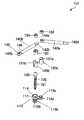
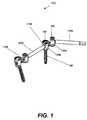
- FIG. 1is a perspective view of a first embodiment of an improved spine fixation apparatus that utilizes multi-axial screw assemblies according to this invention
- FIG. 2is an exploded view of the spine fixation apparatus of FIG. 1 ;
- FIG. 3is a side view of the spine fixation apparatus of FIG. 1 ;
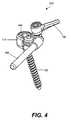
- FIG. 4is a perspective view of another embodiment of an improved spine fixation apparatus that utilizes a multi-axial screw assembly that accommodates both stabilization rods and plates;
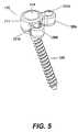
- FIG. 5is a perspective view of the multi-axial screw assembly of FIG. 4 ;
- FIG. 6is a partially exploded view of the spine fixation apparatus of FIG. 4 ;
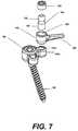
- FIG. 7is another partially exploded view of the spine fixation apparatus of FIG. 4 ;
- FIG. 8is a perspective view of another embodiment of an improved spine fixation apparatus that utilizes a multi-axial screw assembly
- FIG. 9is a perspective view of the multi-axial screw assembly of FIG. 8 with the mounting plates arranged at 180 degrees relative to each other;
- FIG. 10is an exploded view of the spine fixation apparatus of FIG. 8 ;
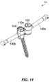
- FIG. 11is a perspective view of another embodiment of an improved spine fixation apparatus that utilizes a multi-axial screw assembly.
- FIG. 12is an exploded view of the spine fixation apparatus of FIG. 1 .
- the inventionprovides a spine fixation apparatus with a multi-axial screw assembly that utilizes a multi-axial screw housing and adjustable, mounting elements for receiving stabilization elements with various geometries
- a spine fixation assembly 100includes mounting assemblies 110 a , 110 b and stabilization rods 140 a , 140 b .
- Stabilization rod 140 bis placed and secured in the mounting assemblies 110 a , 110 b and thereby connects them.
- the mounting assembly 110includes a multiaxial screw housing 111 , two mounting plates 112 a , 112 b extending from the housing 111 and two mounting elements 130 a , 130 b .
- the screw housing 111includes a through opening 114 for receiving a bone screw 120 . Opening 114 extends from the top surface of the screw housing 111 to the bottom surface and has a diameter at the top larger than the diameter at the bottom.
- the bone screw 120has a body 121 with outer threads and a spherical head 122 .
- the body 121is inserted through the opening 114 and is threaded into a vertebral bone (not shown).
- the spherical head 122sits in the opening 114 of the screw housing 111 and the bone screw 120 is oriented at an angle 125 relative to the housing 111 .
- This orientation of the screw 120 relative to the screw housing 111is secured by a setscrew 150 .
- Set screw 150has outer threads that cooperate with inner threads of the opening 114 .
- mounting plates 112 a , 112 bare fixed relative to the screw housing 111 and relative to each other.
- the mounting elements 130 a , 130 bhave a cylindrical shape and slot openings 131 a , 131 b , respectively, shaped and dimensioned to accommodate the ends 144 a , 142 b of the stabilization rods 140 a , 140 b .
- Each stabilization rod 140 a , 140 bhas an elongated cylindrical body, a spherical end 144 a , 144 b and a slotted flat end 142 a , 142 b , respectively.
- the spherical end 144 ahas a flat top 145 a with a concave dimple 146 a .
- the slotted end 142 b of rod 140 bis placed in the slot opening 131 b of the mounting element 130 b and the spherical end 144 a of rod 140 a is placed in the slot opening 131 a of the mounting element 130 a .
- the flat top 145 a with the concave dimple 146 a of end 144 afaces the same side as the flat surface of end 142 b .
- the slotted end 142 bis secured in the opening of the mounting element 130 b with a set screw 154 that has a flat bottom that sits directly onto the flat surface of the slotted end 142 b .
- the spherical end 144 ais secured in the opening of the mounting element 130 a with a set screw 152 that has a pointed bottom that sits directly into the dimple 146 a of the spherical end 144 a .
- Set screws 152 , 154secure the angular position of the rods 140 a , 140 b relative to the mounting elements 130 a , 130 b and therefore relative to the screw housing 111 .
- a spine fixation assembly 102includes a mounting assembly 110 a stabilization rod 140 attached to the mounting assembly 110 and a stabilization plate 160 , also attached to the mounting assembly 110 .
- the mounting assembly 110includes a screw housing 111 and two fixed mounting elements 130 a , 113 b extending from the housing 111 .
- the screw housing 111includes a through opening 114 for receiving a bone screw 120 . Opening 114 extends from the top surface of the screw housing 111 to the bottom surface and has a diameter at the top larger than the diameter at the bottom.
- the bone screw 120has a body 121 with outer threads and a spherical head 122 .
- the body 121is inserted through the opening 114 and is threaded into a vertebral bone (not shown).
- the spherical head 122sits in the opening 114 of the screw housing 111 and the bone screw 120 is oriented at an angle 125 relative to the housing 111 , as shown in FIG. 3 .
- This orientation of the screw 120 relative to the screw housing 111is secured by a setscrew 150 .
- Set screw 150has outer threads that cooperate with inner threads of the opening 114 .
- the mounting elements 130 a , 130 bare fixed relative to the screw housing 111 and relative to each other.
- the mounting elements 130 a , 130 bhave a cylindrical shape and threaded openings 131 a , 131 b , respectively.
- end 149 of the stabilization rod 140is inserted in a bracket 170 that has a cylindrically shaped body 173 for receiving the cylindrically shaped rod end 149 , and a loop 171 extending from the side of the cylindrical body 173 .
- the loop 171is placed onto the mounting element 130 b and is attached to it by inserting a set screw 172 through the loop 171 and screwing it into the opening 131 b .
- a cup shaped end 162 of the stabilization plate 160is placed onto the mounting element 130 a and is attached to it with a plate screw 164 .
- Plate screw 164has a spherical head 165 and a threaded cylindrical bottom 167 .
- the plate screw 164is inserted through the cup opening 163 and the cylindrical bottom is screwed into the threaded opening 131 a .
- the spherical head 165sits in the cup opening 163 .
- the plate 160is positioned at a desired angle relative to the screw housing 111 and the position is locked with a set screw 166 placed on top of the spherical head 165 and tightened down into the cup opening 163 .
- the set screw surface that interfaces with the spherical heard 165 of the plate screw 164is concave and concentric with the spherical head 165 .
- the spine fixation assembly 103includes mounting assemblies 110 a , 110 b (not shown) and stabilization rods 140 a , 140 b .
- Stabilization rods 140 a , 140 bare placed and secured in the mounting assembly 110 a .
- the mounting assembly 110 aincludes a multiaxial screw housing 111 , a fixed mounting plate 112 b extending from the housing 111 and a movable mounting plate 112 a .
- the movable mounting plate 112 ahas an end 115 that is inserted in a side opening 119 of the housing 111 and is allowed to swivel around axis 118 of the housing 111 thereby allowing the angle 126 between the mounting plates 112 a , 112 b to be adjusted.
- Axis 118passes through the center of housing 111 . In other embodiments axis 118 may pass through any other location of the mounting plate 112 a . In the example of FIG. 8 the angle 126 is set to 90 degrees and in the example of FIG. 9 , the angle 126 is set to 180 degrees.
- the screw housing 111includes a through opening 114 for receiving a bone screw 120 .
- Opening 114extends from the top surface of the screw housing 111 to the bottom surface and has a diameter at the top larger than the diameter at the bottom.
- the end 115 of the movable mounting plate 112 that is inserted in the side opening 119 of the housing 111also has a through opening 117 that is concentric with the opening 114 .
- the bone screw 120has a body 121 with outer threads and a spherical head 122 .
- the body 121is inserted through the openings 114 and 117 and is threaded into a vertebral bone (not shown).
- the spherical head 122sits in the opening 114 of the screw housing 111 and the bone screw 120 is oriented at an angle 125 relative to the housing 111 .
- This orientation of the screw 120 relative to the screw housing 111is secured by a setscrew 150 .
- Set screw 150also secures the angle and positioning of the mounting plates 112 a , 112 b relative to each other and the housing 111 .
- the mounting plates 112 a , 112 bhave receiving elements 113 a , 113 b , that are used to attach the mounting elements 130 a , 130 b to the mounting plates 112 a , 112 b , respectively.
- the mounting elements 130 a , 130 bhave a cylindrical shape and side slot openings 132 a , 132 b , respectively, shaped and dimensioned to accommodate the ends 149 a , 148 b of the stabilization rods 140 a , 140 b , respectively. Mounting elements 130 a , 130 b may also rotate around an axis passing through their center.
- Each stabilization rod 140 a , 140 bhas an elongated cylindrical body, and spherical ends 148 a , 149 a , 148 b , 149 b , respectively.
- the spherical ends 148 a , 149 a , 148 b , 149 bhave flat sides 173 a , 173 b opposite to each other.
- the spherical end 149 a of rod 140 ais placed in the slot opening 132 a of the mounting element 130 a and the spherical end 148 b of rod 140 b is placed in the side slot opening 131 b of the mounting element 130 b and are secured with set screws 152 , 154 , respectively.
- the flat sides 177 a , 177 bare oriented parallel to walls of the side slot openings.
- Set screws 152 , 154secure the angular position of the rods 140 a , 140 b relative to the mounting elements 130 a , 130 b and therefore relative to the screw housing 111 .
- the stabilization rodshave hammer shaped rod ends 181 a , 182 a , 181 b , 182 b .
- the mounting elements 130 a , 130 bhave a cylindrical shape, side slot openings 132 a , 132 b , respectively, and accommodate nesting seats 191 a , 191 b , respectively, shaped and dimensioned to accommodate the hammer shaped ends 182 a , 181 b of the stabilization rods 140 a , 140 b , respectively.
- the screws 120may be inserted in any location of adjacent vertebras or even in the same vertebra.
- Typical vertebral location for inserting screwsinclude the pedicles, the vertebral body, the spinous process, the transverse processes the lamina, the sacrum, lateral mass, pars and the occiput.
- spine fixation assembly 100is made of titanium metal. In other examples the spine fixation assembly 100 is made of stainless steel, nickel, gold, silver or alloys thereof, composites, ceramics, plastic, bone, absorbable material or combination thereof.
- bone screw 120has a length of 57 millimeters and a diameter of 6.5 millimeters.
- the stabilization rodsmay have a length in the range of 20 millimeters to 200 millimeters. Other embodiments include the following.
- a hookmay be used instead for a bone screw.
- Rotation axis 118may be perpendicular to plate 112 a and pass through a location of plate 112 a between the receiving element 113 a and end 115 .
- receiving elementmay connect to plate 112 a via a hinge mechanism or any other connection mechanism that allows rotational motion.
- Spine fixation assembly 100may be implanted via a minimally invasive surgical procedure or an open surgery procedure. Spine fixation assembly 100 my be assembled before surgical implantation or after surgical implantation of the components.
Landscapes
- Health & Medical Sciences (AREA)
- Orthopedic Medicine & Surgery (AREA)
- Life Sciences & Earth Sciences (AREA)
- Neurology (AREA)
- Surgery (AREA)
- Heart & Thoracic Surgery (AREA)
- Engineering & Computer Science (AREA)
- Biomedical Technology (AREA)
- Nuclear Medicine, Radiotherapy & Molecular Imaging (AREA)
- Medical Informatics (AREA)
- Molecular Biology (AREA)
- Animal Behavior & Ethology (AREA)
- General Health & Medical Sciences (AREA)
- Public Health (AREA)
- Veterinary Medicine (AREA)
- Surgical Instruments (AREA)
- Prostheses (AREA)
Abstract
Description
Claims (41)
Priority Applications (5)
| Application Number | Priority Date | Filing Date | Title |
|---|---|---|---|
| US11/738,126US8435267B2 (en) | 2006-04-24 | 2007-04-20 | Spine fixation method and apparatus |
| JP2009507911AJP5209607B2 (en) | 2006-04-24 | 2007-04-23 | Improved spinal fixation method and apparatus |
| CN2007800143588ACN101426433B (en) | 2006-04-24 | 2007-04-23 | Improved spinal fixation method and apparatus |
| EP07761085.5AEP2012687B1 (en) | 2006-04-24 | 2007-04-23 | Improved spine fixation apparatus |
| PCT/US2007/067172WO2007127687A2 (en) | 2006-04-24 | 2007-04-23 | Improved spine fixation method and apparatus |
Applications Claiming Priority (2)
| Application Number | Priority Date | Filing Date | Title |
|---|---|---|---|
| US79435506P | 2006-04-24 | 2006-04-24 | |
| US11/738,126US8435267B2 (en) | 2006-04-24 | 2007-04-20 | Spine fixation method and apparatus |
Related Parent Applications (1)
| Application Number | Title | Priority Date | Filing Date |
|---|---|---|---|
| US79435506PContinuation | 2006-04-24 | 2006-04-24 |
Publications (2)
| Publication Number | Publication Date |
|---|---|
| US20070250061A1 US20070250061A1 (en) | 2007-10-25 |
| US8435267B2true US8435267B2 (en) | 2013-05-07 |
Family
ID=38620432
Family Applications (1)
| Application Number | Title | Priority Date | Filing Date |
|---|---|---|---|
| US11/738,126Active - Reinstated2031-06-16US8435267B2 (en) | 2006-04-24 | 2007-04-20 | Spine fixation method and apparatus |
Country Status (5)
| Country | Link |
|---|---|
| US (1) | US8435267B2 (en) |
| EP (1) | EP2012687B1 (en) |
| JP (1) | JP5209607B2 (en) |
| CN (1) | CN101426433B (en) |
| WO (1) | WO2007127687A2 (en) |
Cited By (6)
| Publication number | Priority date | Publication date | Assignee | Title |
|---|---|---|---|---|
| US20140277163A1 (en)* | 2013-03-15 | 2014-09-18 | Ryan Kretzer | Reinforcement systems for spine stabilization constructs |
| US8992579B1 (en)* | 2011-03-08 | 2015-03-31 | Nuvasive, Inc. | Lateral fixation constructs and related methods |
| US9060815B1 (en) | 2012-03-08 | 2015-06-23 | Nuvasive, Inc. | Systems and methods for performing spine surgery |
| US9517089B1 (en) | 2013-10-08 | 2016-12-13 | Nuvasive, Inc. | Bone anchor with offset rod connector |
| US9820780B2 (en) | 2015-09-30 | 2017-11-21 | Amendia, Inc. | Angled offset tulip assembly |
| US20230240724A1 (en)* | 2019-05-22 | 2023-08-03 | Nuvasive, Inc. | Posterior spinal fixation screws |
Families Citing this family (124)
| Publication number | Priority date | Publication date | Assignee | Title |
|---|---|---|---|---|
| US7833250B2 (en) | 2004-11-10 | 2010-11-16 | Jackson Roger P | Polyaxial bone screw with helically wound capture connection |
| US8292926B2 (en) | 2005-09-30 | 2012-10-23 | Jackson Roger P | Dynamic stabilization connecting member with elastic core and outer sleeve |
| US7862587B2 (en) | 2004-02-27 | 2011-01-04 | Jackson Roger P | Dynamic stabilization assemblies, tool set and method |
| US10729469B2 (en) | 2006-01-09 | 2020-08-04 | Roger P. Jackson | Flexible spinal stabilization assembly with spacer having off-axis core member |
| US10258382B2 (en) | 2007-01-18 | 2019-04-16 | Roger P. Jackson | Rod-cord dynamic connection assemblies with slidable bone anchor attachment members along the cord |
| US8353932B2 (en) | 2005-09-30 | 2013-01-15 | Jackson Roger P | Polyaxial bone anchor assembly with one-piece closure, pressure insert and plastic elongate member |
| US8876868B2 (en) | 2002-09-06 | 2014-11-04 | Roger P. Jackson | Helical guide and advancement flange with radially loaded lip |
| WO2006052796A2 (en) | 2004-11-10 | 2006-05-18 | Jackson Roger P | Helical guide and advancement flange with break-off extensions |
| US6716214B1 (en) | 2003-06-18 | 2004-04-06 | Roger P. Jackson | Polyaxial bone screw with spline capture connection |
| US7621918B2 (en) | 2004-11-23 | 2009-11-24 | Jackson Roger P | Spinal fixation tool set and method |
| US7377923B2 (en) | 2003-05-22 | 2008-05-27 | Alphatec Spine, Inc. | Variable angle spinal screw assembly |
| US8257398B2 (en) | 2003-06-18 | 2012-09-04 | Jackson Roger P | Polyaxial bone screw with cam capture |
| US7776067B2 (en) | 2005-05-27 | 2010-08-17 | Jackson Roger P | Polyaxial bone screw with shank articulation pressure insert and method |
| US7766915B2 (en) | 2004-02-27 | 2010-08-03 | Jackson Roger P | Dynamic fixation assemblies with inner core and outer coil-like member |
| US8926670B2 (en) | 2003-06-18 | 2015-01-06 | Roger P. Jackson | Polyaxial bone screw assembly |
| US7967850B2 (en) | 2003-06-18 | 2011-06-28 | Jackson Roger P | Polyaxial bone anchor with helical capture connection, insert and dual locking assembly |
| US8137386B2 (en) | 2003-08-28 | 2012-03-20 | Jackson Roger P | Polyaxial bone screw apparatus |
| US8398682B2 (en) | 2003-06-18 | 2013-03-19 | Roger P. Jackson | Polyaxial bone screw assembly |
| US8377102B2 (en) | 2003-06-18 | 2013-02-19 | Roger P. Jackson | Polyaxial bone anchor with spline capture connection and lower pressure insert |
| US7179261B2 (en) | 2003-12-16 | 2007-02-20 | Depuy Spine, Inc. | Percutaneous access devices and bone anchor assemblies |
| US11419642B2 (en) | 2003-12-16 | 2022-08-23 | Medos International Sarl | Percutaneous access devices and bone anchor assemblies |
| US7527638B2 (en) | 2003-12-16 | 2009-05-05 | Depuy Spine, Inc. | Methods and devices for minimally invasive spinal fixation element placement |
| US11241261B2 (en) | 2005-09-30 | 2022-02-08 | Roger P Jackson | Apparatus and method for soft spinal stabilization using a tensionable cord and releasable end structure |
| JP2007525274A (en) | 2004-02-27 | 2007-09-06 | ロジャー・ピー・ジャクソン | Orthopedic implant rod reduction instrument set and method |
| US8152810B2 (en) | 2004-11-23 | 2012-04-10 | Jackson Roger P | Spinal fixation tool set and method |
| US7160300B2 (en) | 2004-02-27 | 2007-01-09 | Jackson Roger P | Orthopedic implant rod reduction tool set and method |
| US7651502B2 (en) | 2004-09-24 | 2010-01-26 | Jackson Roger P | Spinal fixation tool set and method for rod reduction and fastener insertion |
| US8926672B2 (en) | 2004-11-10 | 2015-01-06 | Roger P. Jackson | Splay control closure for open bone anchor |
| US8444681B2 (en) | 2009-06-15 | 2013-05-21 | Roger P. Jackson | Polyaxial bone anchor with pop-on shank, friction fit retainer and winged insert |
| US9168069B2 (en) | 2009-06-15 | 2015-10-27 | Roger P. Jackson | Polyaxial bone anchor with pop-on shank and winged insert with lower skirt for engaging a friction fit retainer |
| US9980753B2 (en) | 2009-06-15 | 2018-05-29 | Roger P Jackson | pivotal anchor with snap-in-place insert having rotation blocking extensions |
| US9216041B2 (en) | 2009-06-15 | 2015-12-22 | Roger P. Jackson | Spinal connecting members with tensioned cords and rigid sleeves for engaging compression inserts |
| WO2006057837A1 (en) | 2004-11-23 | 2006-06-01 | Jackson Roger P | Spinal fixation tool attachment structure |
| US8308782B2 (en) | 2004-11-23 | 2012-11-13 | Jackson Roger P | Bone anchors with longitudinal connecting member engaging inserts and closures for fixation and optional angulation |
| US7875065B2 (en) | 2004-11-23 | 2011-01-25 | Jackson Roger P | Polyaxial bone screw with multi-part shank retainer and pressure insert |
| US7901437B2 (en) | 2007-01-26 | 2011-03-08 | Jackson Roger P | Dynamic stabilization member with molded connection |
| US10076361B2 (en) | 2005-02-22 | 2018-09-18 | Roger P. Jackson | Polyaxial bone screw with spherical capture, compression and alignment and retention structures |
| US8105368B2 (en) | 2005-09-30 | 2012-01-31 | Jackson Roger P | Dynamic stabilization connecting member with slitted core and outer sleeve |
| US8100946B2 (en) | 2005-11-21 | 2012-01-24 | Synthes Usa, Llc | Polyaxial bone anchors with increased angulation |
| US20080058808A1 (en) | 2006-06-14 | 2008-03-06 | Spartek Medical, Inc. | Implant system and method to treat degenerative disorders of the spine |
| CA2670988C (en) | 2006-12-08 | 2014-03-25 | Roger P. Jackson | Tool system for dynamic spinal implants |
| US8366745B2 (en) | 2007-05-01 | 2013-02-05 | Jackson Roger P | Dynamic stabilization assembly having pre-compressed spacers with differential displacements |
| US8475498B2 (en) | 2007-01-18 | 2013-07-02 | Roger P. Jackson | Dynamic stabilization connecting member with cord connection |
| US10792074B2 (en) | 2007-01-22 | 2020-10-06 | Roger P. Jackson | Pivotal bone anchor assemly with twist-in-place friction fit insert |
| US10383660B2 (en) | 2007-05-01 | 2019-08-20 | Roger P. Jackson | Soft stabilization assemblies with pretensioned cords |
| US8979904B2 (en) | 2007-05-01 | 2015-03-17 | Roger P Jackson | Connecting member with tensioned cord, low profile rigid sleeve and spacer with torsion control |
| US8083772B2 (en) | 2007-06-05 | 2011-12-27 | Spartek Medical, Inc. | Dynamic spinal rod assembly and method for dynamic stabilization of the spine |
| US8114134B2 (en) | 2007-06-05 | 2012-02-14 | Spartek Medical, Inc. | Spinal prosthesis having a three bar linkage for motion preservation and dynamic stabilization of the spine |
| US8109970B2 (en) | 2007-06-05 | 2012-02-07 | Spartek Medical, Inc. | Deflection rod system with a deflection contouring shield for a spine implant and method |
| US8092501B2 (en) | 2007-06-05 | 2012-01-10 | Spartek Medical, Inc. | Dynamic spinal rod and method for dynamic stabilization of the spine |
| US8052722B2 (en) | 2007-06-05 | 2011-11-08 | Spartek Medical, Inc. | Dual deflection rod system for a dynamic stabilization and motion preservation spinal implantation system and method |
| US8048128B2 (en) | 2007-06-05 | 2011-11-01 | Spartek Medical, Inc. | Revision system and method for a dynamic stabilization and motion preservation spinal implantation system and method |
| US8048115B2 (en) | 2007-06-05 | 2011-11-01 | Spartek Medical, Inc. | Surgical tool and method for implantation of a dynamic bone anchor |
| US8048123B2 (en) | 2007-06-05 | 2011-11-01 | Spartek Medical, Inc. | Spine implant with a deflection rod system and connecting linkages and method |
| US8021396B2 (en) | 2007-06-05 | 2011-09-20 | Spartek Medical, Inc. | Configurable dynamic spinal rod and method for dynamic stabilization of the spine |
| US9439681B2 (en) | 2007-07-20 | 2016-09-13 | DePuy Synthes Products, Inc. | Polyaxial bone fixation element |
| US8057517B2 (en) | 2008-02-26 | 2011-11-15 | Spartek Medical, Inc. | Load-sharing component having a deflectable post and centering spring and method for dynamic stabilization of the spine |
| US8083775B2 (en) | 2008-02-26 | 2011-12-27 | Spartek Medical, Inc. | Load-sharing bone anchor having a natural center of rotation and method for dynamic stabilization of the spine |
| US8333792B2 (en) | 2008-02-26 | 2012-12-18 | Spartek Medical, Inc. | Load-sharing bone anchor having a deflectable post and method for dynamic stabilization of the spine |
| US8337536B2 (en) | 2008-02-26 | 2012-12-25 | Spartek Medical, Inc. | Load-sharing bone anchor having a deflectable post with a compliant ring and method for stabilization of the spine |
| US8267979B2 (en) | 2008-02-26 | 2012-09-18 | Spartek Medical, Inc. | Load-sharing bone anchor having a deflectable post and axial spring and method for dynamic stabilization of the spine |
| US8211155B2 (en) | 2008-02-26 | 2012-07-03 | Spartek Medical, Inc. | Load-sharing bone anchor having a durable compliant member and method for dynamic stabilization of the spine |
| US8048125B2 (en)* | 2008-02-26 | 2011-11-01 | Spartek Medical, Inc. | Versatile offset polyaxial connector and method for dynamic stabilization of the spine |
| US8097024B2 (en) | 2008-02-26 | 2012-01-17 | Spartek Medical, Inc. | Load-sharing bone anchor having a deflectable post and method for stabilization of the spine |
| US8007518B2 (en) | 2008-02-26 | 2011-08-30 | Spartek Medical, Inc. | Load-sharing component having a deflectable post and method for dynamic stabilization of the spine |
| AU2010260521C1 (en) | 2008-08-01 | 2013-08-01 | Roger P. Jackson | Longitudinal connecting member with sleeved tensioned cords |
| JP5815407B2 (en) | 2008-09-12 | 2015-11-17 | ジンテス ゲゼルシャフト ミット ベシュレンクテル ハフツング | Spinal stabilization and guided fixation system |
| KR20110081208A (en) | 2008-09-29 | 2011-07-13 | 신세스 게엠바하 | Multi-Axis Bottom-Loading Screw and Rod Assemblies |
| US20140012322A1 (en)* | 2008-10-10 | 2014-01-09 | Brian Gayvey | Bone Screw |
| EP2370011B1 (en)* | 2008-10-15 | 2013-04-10 | Zimmer Spine | A spinal construction assembly comprising an interconnecting device |
| CA2742399A1 (en) | 2008-11-03 | 2010-06-03 | Dustin M. Harvey | Uni-planar bone fixation assembly |
| WO2010108655A2 (en)* | 2009-03-26 | 2010-09-30 | Franz Copf | Spine fixation system |
| KR20120013312A (en) | 2009-04-15 | 2012-02-14 | 신세스 게엠바하 | Orthodontic Connectors for Spinal Structures |
| US8372120B2 (en) | 2009-05-20 | 2013-02-12 | Spine Wave, Inc. | Multi-axial cross connector |
| US8430913B2 (en)* | 2009-06-10 | 2013-04-30 | Spine Wave, Inc. | Devices and methods for adding an additional level of fixation to an existing construct |
| CN103826560A (en) | 2009-06-15 | 2014-05-28 | 罗杰.P.杰克逊 | Polyaxial Bone Anchor with Socket Stem and Winged Inserts with Friction Fit Compression Collars |
| US9668771B2 (en) | 2009-06-15 | 2017-06-06 | Roger P Jackson | Soft stabilization assemblies with off-set connector |
| US8998959B2 (en) | 2009-06-15 | 2015-04-07 | Roger P Jackson | Polyaxial bone anchors with pop-on shank, fully constrained friction fit retainer and lock and release insert |
| US11229457B2 (en) | 2009-06-15 | 2022-01-25 | Roger P. Jackson | Pivotal bone anchor assembly with insert tool deployment |
| CA2764841A1 (en)* | 2009-06-17 | 2010-12-23 | Synthes Usa, Llc | Revision connector for spinal constructs |
| US8529609B2 (en) | 2009-12-01 | 2013-09-10 | Osteomed Llc | Polyaxial facet fixation screw system |
| EP2485654B1 (en) | 2009-10-05 | 2021-05-05 | Jackson P. Roger | Polyaxial bone anchor with non-pivotable retainer and pop-on shank, some with friction fit |
| US9078707B2 (en) | 2009-12-01 | 2015-07-14 | Osteomed Llc | Polyaxial facet fixation screw system with cannula inserter |
| US8998966B2 (en) | 2009-12-01 | 2015-04-07 | Osteomed, Llc | Polyaxial facet fixation screw system with fixation augmentation |
| CN102695465A (en) | 2009-12-02 | 2012-09-26 | 斯帕泰克医疗股份有限公司 | Low profile spinal prosthesis incorporating a bone anchor having a deflectable post and a compound spinal rod |
| US12383311B2 (en) | 2010-05-14 | 2025-08-12 | Roger P. Jackson | Pivotal bone anchor assembly and method for use thereof |
| US20110307015A1 (en) | 2010-06-10 | 2011-12-15 | Spartek Medical, Inc. | Adaptive spinal rod and methods for stabilization of the spine |
| AU2011299558A1 (en) | 2010-09-08 | 2013-05-02 | Roger P. Jackson | Dynamic stabilization members with elastic and inelastic sections |
| AU2011324058A1 (en) | 2010-11-02 | 2013-06-20 | Roger P. Jackson | Polyaxial bone anchor with pop-on shank and pivotable retainer |
| US9387013B1 (en) | 2011-03-01 | 2016-07-12 | Nuvasive, Inc. | Posterior cervical fixation system |
| US9247964B1 (en) | 2011-03-01 | 2016-02-02 | Nuasive, Inc. | Spinal Cross-connector |
| JP5865479B2 (en) | 2011-03-24 | 2016-02-17 | ロジャー・ピー・ジャクソン | Multiaxial bone anchor with compound joint and pop-mounted shank |
| US8740950B2 (en) | 2011-12-08 | 2014-06-03 | Spine Wave, Inc. | Methods for percutaneously attaching a cross connector to contralateral spinal constructs |
| US8911479B2 (en) | 2012-01-10 | 2014-12-16 | Roger P. Jackson | Multi-start closures for open implants |
| US8430916B1 (en) | 2012-02-07 | 2013-04-30 | Spartek Medical, Inc. | Spinal rod connectors, methods of use, and spinal prosthesis incorporating spinal rod connectors |
| US9023087B2 (en)* | 2012-11-09 | 2015-05-05 | Blackstone Medical, Inc. | Percutaneous modular head-to-head cross connector |
| US8911478B2 (en) | 2012-11-21 | 2014-12-16 | Roger P. Jackson | Splay control closure for open bone anchor |
| US10058354B2 (en) | 2013-01-28 | 2018-08-28 | Roger P. Jackson | Pivotal bone anchor assembly with frictional shank head seating surfaces |
| US8852239B2 (en) | 2013-02-15 | 2014-10-07 | Roger P Jackson | Sagittal angle screw with integral shank and receiver |
| US9775650B2 (en)* | 2013-03-11 | 2017-10-03 | Dynamic Spine, Llc | Screw clamp orthopedic device and methods of implementation |
| WO2015023420A2 (en) | 2013-07-25 | 2015-02-19 | Latitude Holdings, Llc | Percutaneous pedicle screw revision system |
| US20150094769A1 (en) | 2013-10-01 | 2015-04-02 | Hamid Abbasi | System and method for lengthening an existing spinal support structure |
| US9566092B2 (en) | 2013-10-29 | 2017-02-14 | Roger P. Jackson | Cervical bone anchor with collet retainer and outer locking sleeve |
| US9717533B2 (en) | 2013-12-12 | 2017-08-01 | Roger P. Jackson | Bone anchor closure pivot-splay control flange form guide and advancement structure |
| US9451993B2 (en) | 2014-01-09 | 2016-09-27 | Roger P. Jackson | Bi-radial pop-on cervical bone anchor |
| US9597119B2 (en) | 2014-06-04 | 2017-03-21 | Roger P. Jackson | Polyaxial bone anchor with polymer sleeve |
| US10064658B2 (en) | 2014-06-04 | 2018-09-04 | Roger P. Jackson | Polyaxial bone anchor with insert guides |
| US9603634B1 (en) | 2015-11-13 | 2017-03-28 | Amendia, Inc. | Percutaneous rod-to-rod cross connector |
| ES2878182T3 (en)* | 2015-12-17 | 2021-11-18 | Ali Fahir Ozer | Double-headed pedicle screw |
| US10321939B2 (en) | 2016-05-18 | 2019-06-18 | Medos International Sarl | Implant connectors and related methods |
| US10517647B2 (en) | 2016-05-18 | 2019-12-31 | Medos International Sarl | Implant connectors and related methods |
| US10786285B2 (en) | 2016-06-06 | 2020-09-29 | Stryker European Holdings I, Llc | Paraxial revision rod-to-rod connector |
| EP3278751B1 (en) | 2016-07-15 | 2024-03-06 | Stryker European Operations Holdings LLC | Spinal fixation assembly |
| US10398476B2 (en) | 2016-12-13 | 2019-09-03 | Medos International Sàrl | Implant adapters and related methods |
| US10492835B2 (en) | 2016-12-19 | 2019-12-03 | Medos International Sàrl | Offset rods, offset rod connectors, and related methods |
| US10238432B2 (en)* | 2017-02-10 | 2019-03-26 | Medos International Sàrl | Tandem rod connectors and related methods |
| US20180228516A1 (en)* | 2017-02-14 | 2018-08-16 | Warsaw Orthopedic, Inc. | Spinal implant system and method |
| US10736665B2 (en) | 2017-02-24 | 2020-08-11 | Warsaw Orthopedic, Inc. | Spinal implant system and method |
| US10966761B2 (en) | 2017-03-28 | 2021-04-06 | Medos International Sarl | Articulating implant connectors and related methods |
| US10561454B2 (en) | 2017-03-28 | 2020-02-18 | Medos International Sarl | Articulating implant connectors and related methods |
| US11076890B2 (en) | 2017-12-01 | 2021-08-03 | Medos International Sàrl | Rod-to-rod connectors having robust rod closure mechanisms and related methods |
| WO2020154435A1 (en)* | 2019-01-22 | 2020-07-30 | Life Spine, Inc | Polyaxial spine screw rod holder having a second, offset rod holder |
| US11311317B2 (en) | 2019-09-25 | 2022-04-26 | Stelios KOUTSOUMBELIS | Spinal fixation device with rotatable connector |
| JP2025529435A (en)* | 2022-09-13 | 2025-09-04 | メドス・インターナショナル・エスエイアールエル | Modular Connector Assembly |
Citations (31)
| Publication number | Priority date | Publication date | Assignee | Title |
|---|---|---|---|---|
| US5645599A (en) | 1994-07-26 | 1997-07-08 | Fixano | Interspinal vertebral implant |
| US5728097A (en) | 1992-03-17 | 1998-03-17 | Sdgi Holding, Inc. | Method for subcutaneous suprafascial internal fixation |
| US5882344A (en) | 1995-10-18 | 1999-03-16 | Stouder, Jr.; Albert E. | Adjustable length cannula and trocar |
| US5938663A (en) | 1995-03-06 | 1999-08-17 | Stryker France, S.A. | Spinal instruments, particularly for a rod |
| US6440137B1 (en)* | 2000-04-18 | 2002-08-27 | Andres A. Horvath | Medical fastener cap system |
| US6482207B1 (en) | 2000-07-13 | 2002-11-19 | Fastenetix, Llc | Efficient assembling modular locking pedicle screw |
| US20030040746A1 (en) | 2001-07-20 | 2003-02-27 | Mitchell Margaret E. | Spinal stabilization system and method |
| US20030216736A1 (en) | 2002-05-17 | 2003-11-20 | Robinson James C. | Device for fixation of spinous processes |
| US6685705B1 (en) | 2000-10-23 | 2004-02-03 | Sdgi Holdings, Inc. | Six-axis and seven-axis adjustable connector |
| US20040039384A1 (en) | 2002-08-21 | 2004-02-26 | Boehm Frank H. | Device and method for pertcutaneous placement of lumbar pedicle screws and connecting rods |
| US6802844B2 (en) | 2001-03-26 | 2004-10-12 | Nuvasive, Inc | Spinal alignment apparatus and methods |
| US7090674B2 (en) | 2003-11-03 | 2006-08-15 | Spinal, Llc | Bone fixation system with low profile fastener |
| US20060247640A1 (en) | 2005-04-29 | 2006-11-02 | Sdgi Holdings, Inc. | Spinous process stabilization devices and methods |
| US20060293662A1 (en) | 2005-06-13 | 2006-12-28 | Boyer Michael L Ii | Spinous process spacer |
| WO2007000020A1 (en) | 2005-06-29 | 2007-01-04 | Compumedics Limited | Sensor assembly with conductive bridge |
| US7166109B2 (en) | 2001-10-23 | 2007-01-23 | Biedermann Motech Gmbh | Bone fixation device and screw therefor |
| WO2007070819A2 (en) | 2005-12-14 | 2007-06-21 | Spinefrontier Lls | Spinous process fixation implant |
| US7303563B2 (en)* | 2004-06-17 | 2007-12-04 | Sdgi Holdings, Inc. | Orthopedic fixation system and method of use |
| US20080167655A1 (en) | 2007-01-05 | 2008-07-10 | Jeffrey Chun Wang | Interspinous implant, tools and methods of implanting |
| US20080183211A1 (en) | 2007-01-11 | 2008-07-31 | Lanx, Llc | Spinous process implants and associated methods |
| US7618443B2 (en)* | 2004-06-14 | 2009-11-17 | Abdou M Samy | Occipito fixation system and method of use |
| WO2010000020A1 (en) | 2008-06-30 | 2010-01-07 | Cathrx Ltd | A catheter |
| WO2010016949A1 (en) | 2008-08-08 | 2010-02-11 | Alphatec Spine, Inc. | Spinous process device and method of use |
| US20100087860A1 (en) | 2006-12-12 | 2010-04-08 | Spinefrontier, Inc | Spinous process fixation implant |
| US20100087869A1 (en) | 2008-08-18 | 2010-04-08 | Abdou M Samy | Devices and methods to limit aberrant movement of the vertebral bones |
| US7722651B2 (en)* | 2005-10-21 | 2010-05-25 | Depuy Spine, Inc. | Adjustable bone screw assembly |
| US7740649B2 (en)* | 2004-02-26 | 2010-06-22 | Pioneer Surgical Technology, Inc. | Bone plate system and methods |
| WO2011000020A1 (en) | 2009-06-12 | 2011-01-06 | Sbc Research Pty Ltd | Enhanced method of detection |
| US20110022090A1 (en) | 2009-06-23 | 2011-01-27 | Osteomed, L.P. | Spinous process fusion implants |
| WO2011031924A2 (en) | 2009-09-11 | 2011-03-17 | Globus Medical, Inc. | Spinous process fusion devices |
| US20110144692A1 (en) | 2008-08-13 | 2011-06-16 | Synthes Usa, Llc | Interspinous spacer assembly |
Family Cites Families (9)
| Publication number | Priority date | Publication date | Assignee | Title |
|---|---|---|---|---|
| US5261909A (en)* | 1992-02-18 | 1993-11-16 | Danek Medical, Inc. | Variable angle screw for spinal implant system |
| US5437669A (en)* | 1993-08-12 | 1995-08-01 | Amei Technologies Inc. | Spinal fixation systems with bifurcated connectors |
| US5545166A (en)* | 1994-07-14 | 1996-08-13 | Advanced Spine Fixation Systems, Incorporated | Spinal segmental reduction derotational fixation system |
| FR2784282B1 (en)* | 1998-10-09 | 2001-03-23 | Dimso Sa | SPINAL OSTEOSYNTHESIS SYSTEM WITH IMPROVED RIGIDITY |
| WO2000015125A1 (en)* | 1998-09-11 | 2000-03-23 | Synthes Ag Chur | Variable angle spinal fixation system |
| US6524315B1 (en)* | 2000-08-08 | 2003-02-25 | Depuy Acromed, Inc. | Orthopaedic rod/plate locking mechanism |
| US20060064092A1 (en)* | 2001-05-17 | 2006-03-23 | Howland Robert S | Selective axis serrated rod low profile spinal fixation system |
| US7648520B2 (en)* | 2004-04-16 | 2010-01-19 | Kyphon Sarl | Pedicle screw assembly |
| BG65395B1 (en)* | 2004-10-13 | 2008-06-30 | Станислав Несторов | System for spinal column stabilization |
- 2007
- 2007-04-20USUS11/738,126patent/US8435267B2/enactiveActive - Reinstated
- 2007-04-23JPJP2009507911Apatent/JP5209607B2/ennot_activeExpired - Fee Related
- 2007-04-23CNCN2007800143588Apatent/CN101426433B/ennot_activeExpired - Fee Related
- 2007-04-23EPEP07761085.5Apatent/EP2012687B1/ennot_activeNot-in-force
- 2007-04-23WOPCT/US2007/067172patent/WO2007127687A2/enactiveApplication Filing
Patent Citations (37)
| Publication number | Priority date | Publication date | Assignee | Title |
|---|---|---|---|---|
| US6793656B1 (en) | 1992-03-17 | 2004-09-21 | Sdgi Holdings, Inc. | Systems and methods for fixation of adjacent vertebrae |
| US5728097A (en) | 1992-03-17 | 1998-03-17 | Sdgi Holding, Inc. | Method for subcutaneous suprafascial internal fixation |
| US5645599A (en) | 1994-07-26 | 1997-07-08 | Fixano | Interspinal vertebral implant |
| US5938663A (en) | 1995-03-06 | 1999-08-17 | Stryker France, S.A. | Spinal instruments, particularly for a rod |
| US5882344A (en) | 1995-10-18 | 1999-03-16 | Stouder, Jr.; Albert E. | Adjustable length cannula and trocar |
| US6440137B1 (en)* | 2000-04-18 | 2002-08-27 | Andres A. Horvath | Medical fastener cap system |
| US6482207B1 (en) | 2000-07-13 | 2002-11-19 | Fastenetix, Llc | Efficient assembling modular locking pedicle screw |
| US6685705B1 (en) | 2000-10-23 | 2004-02-03 | Sdgi Holdings, Inc. | Six-axis and seven-axis adjustable connector |
| US6802844B2 (en) | 2001-03-26 | 2004-10-12 | Nuvasive, Inc | Spinal alignment apparatus and methods |
| US20030040746A1 (en) | 2001-07-20 | 2003-02-27 | Mitchell Margaret E. | Spinal stabilization system and method |
| US7166109B2 (en) | 2001-10-23 | 2007-01-23 | Biedermann Motech Gmbh | Bone fixation device and screw therefor |
| EP1418854A1 (en) | 2002-05-17 | 2004-05-19 | SDGI Holdings, Inc. | Device for fixation of spinous processes |
| US20030216736A1 (en) | 2002-05-17 | 2003-11-20 | Robinson James C. | Device for fixation of spinous processes |
| US20040039384A1 (en) | 2002-08-21 | 2004-02-26 | Boehm Frank H. | Device and method for pertcutaneous placement of lumbar pedicle screws and connecting rods |
| US7090674B2 (en) | 2003-11-03 | 2006-08-15 | Spinal, Llc | Bone fixation system with low profile fastener |
| US7740649B2 (en)* | 2004-02-26 | 2010-06-22 | Pioneer Surgical Technology, Inc. | Bone plate system and methods |
| US7618443B2 (en)* | 2004-06-14 | 2009-11-17 | Abdou M Samy | Occipito fixation system and method of use |
| US7303563B2 (en)* | 2004-06-17 | 2007-12-04 | Sdgi Holdings, Inc. | Orthopedic fixation system and method of use |
| US20060247640A1 (en) | 2005-04-29 | 2006-11-02 | Sdgi Holdings, Inc. | Spinous process stabilization devices and methods |
| US20060293662A1 (en) | 2005-06-13 | 2006-12-28 | Boyer Michael L Ii | Spinous process spacer |
| WO2007000020A1 (en) | 2005-06-29 | 2007-01-04 | Compumedics Limited | Sensor assembly with conductive bridge |
| US7722651B2 (en)* | 2005-10-21 | 2010-05-25 | Depuy Spine, Inc. | Adjustable bone screw assembly |
| WO2007070819A2 (en) | 2005-12-14 | 2007-06-21 | Spinefrontier Lls | Spinous process fixation implant |
| US20070179500A1 (en) | 2005-12-14 | 2007-08-02 | Spinefrontier Lls | Spinous process fixation implant |
| US20070233082A1 (en) | 2005-12-14 | 2007-10-04 | Spinefrontier Lls | Spinous process fixation implant |
| US20070162001A1 (en) | 2005-12-14 | 2007-07-12 | Spinefrontier Lls | Spinous process fixation implant |
| US20100087860A1 (en) | 2006-12-12 | 2010-04-08 | Spinefrontier, Inc | Spinous process fixation implant |
| US20080167655A1 (en) | 2007-01-05 | 2008-07-10 | Jeffrey Chun Wang | Interspinous implant, tools and methods of implanting |
| US20080183211A1 (en) | 2007-01-11 | 2008-07-31 | Lanx, Llc | Spinous process implants and associated methods |
| WO2010000020A1 (en) | 2008-06-30 | 2010-01-07 | Cathrx Ltd | A catheter |
| WO2010016949A1 (en) | 2008-08-08 | 2010-02-11 | Alphatec Spine, Inc. | Spinous process device and method of use |
| US20110144692A1 (en) | 2008-08-13 | 2011-06-16 | Synthes Usa, Llc | Interspinous spacer assembly |
| US20100087869A1 (en) | 2008-08-18 | 2010-04-08 | Abdou M Samy | Devices and methods to limit aberrant movement of the vertebral bones |
| WO2010068829A2 (en) | 2008-12-12 | 2010-06-17 | Spinefrontier, Inc. | Improved spinous process fixation implant |
| WO2011000020A1 (en) | 2009-06-12 | 2011-01-06 | Sbc Research Pty Ltd | Enhanced method of detection |
| US20110022090A1 (en) | 2009-06-23 | 2011-01-27 | Osteomed, L.P. | Spinous process fusion implants |
| WO2011031924A2 (en) | 2009-09-11 | 2011-03-17 | Globus Medical, Inc. | Spinous process fusion devices |
Cited By (7)
| Publication number | Priority date | Publication date | Assignee | Title |
|---|---|---|---|---|
| US8992579B1 (en)* | 2011-03-08 | 2015-03-31 | Nuvasive, Inc. | Lateral fixation constructs and related methods |
| US9060815B1 (en) | 2012-03-08 | 2015-06-23 | Nuvasive, Inc. | Systems and methods for performing spine surgery |
| US9579131B1 (en) | 2012-03-08 | 2017-02-28 | Nuvasive, Inc. | Systems and methods for performing spine surgery |
| US20140277163A1 (en)* | 2013-03-15 | 2014-09-18 | Ryan Kretzer | Reinforcement systems for spine stabilization constructs |
| US9517089B1 (en) | 2013-10-08 | 2016-12-13 | Nuvasive, Inc. | Bone anchor with offset rod connector |
| US9820780B2 (en) | 2015-09-30 | 2017-11-21 | Amendia, Inc. | Angled offset tulip assembly |
| US20230240724A1 (en)* | 2019-05-22 | 2023-08-03 | Nuvasive, Inc. | Posterior spinal fixation screws |
Also Published As
| Publication number | Publication date |
|---|---|
| WO2007127687A3 (en) | 2008-07-17 |
| EP2012687A4 (en) | 2012-04-18 |
| US20070250061A1 (en) | 2007-10-25 |
| JP2009534167A (en) | 2009-09-24 |
| EP2012687B1 (en) | 2013-06-26 |
| JP5209607B2 (en) | 2013-06-12 |
| EP2012687A2 (en) | 2009-01-14 |
| CN101426433A (en) | 2009-05-06 |
| WO2007127687A2 (en) | 2007-11-08 |
| CN101426433B (en) | 2013-08-21 |
Similar Documents
| Publication | Publication Date | Title |
|---|---|---|
| US8435267B2 (en) | Spine fixation method and apparatus | |
| US11992245B2 (en) | Adjustable implant assembly | |
| US7175622B2 (en) | Spinal rod system | |
| US8845700B2 (en) | Adjustable bone screw assembly | |
| US9532811B2 (en) | Jointed rod | |
| US8313515B2 (en) | Multi-level spinal stabilization system | |
| JP4981689B2 (en) | Spinal fixation device | |
| AU680209B2 (en) | Spinal rod transverse connector for supporting vertebral fixation elements | |
| US8690924B2 (en) | Spinal screw assembly | |
| EP2410934B1 (en) | Spine fixation system | |
| US20060089645A1 (en) | Internal fixation system for spine surgery | |
| JP2016120310A (en) | Spine stabilization system | |
| US20090125067A1 (en) | In-line occipital plate and method of use | |
| US20240180594A1 (en) | Monoaxial - uniplanar hybrid screw |
Legal Events
| Date | Code | Title | Description |
|---|---|---|---|
| REMI | Maintenance fee reminder mailed | ||
| LAPS | Lapse for failure to pay maintenance fees | ||
| FP | Lapsed due to failure to pay maintenance fee | Effective date:20170507 | |
| FEPP | Fee payment procedure | Free format text:SURCHARGE, PETITION TO ACCEPT PYMT AFTER EXP, UNINTENTIONAL. (ORIGINAL EVENT CODE: M2558); ENTITY STATUS OF PATENT OWNER: SMALL ENTITY Free format text:PETITION RELATED TO MAINTENANCE FEES GRANTED (ORIGINAL EVENT CODE: PMFG) Free format text:PETITION RELATED TO MAINTENANCE FEES FILED (ORIGINAL EVENT CODE: PMFP) | |
| MAFP | Maintenance fee payment | Free format text:PAYMENT OF MAINTENANCE FEE, 4TH YR, SMALL ENTITY (ORIGINAL EVENT CODE: M2551) Year of fee payment:4 | |
| PRDP | Patent reinstated due to the acceptance of a late maintenance fee | Effective date:20180430 | |
| STCF | Information on status: patent grant | Free format text:PATENTED CASE | |
| AS | Assignment | Owner name:KIC VENTURES, LLC, MASSACHUSETTS Free format text:ASSIGNMENT OF ASSIGNORS INTEREST;ASSIGNOR:SPINEFRONTIER, INC;REEL/FRAME:053972/0737 Effective date:20190701 | |
| AS | Assignment | Owner name:KIC VENTURES, LLC, MASSACHUSETTS Free format text:ASSIGNMENT OF ASSIGNORS INTEREST;ASSIGNOR:SPINEFRONTIER, LLS;REEL/FRAME:054027/0319 Effective date:20190701 | |
| FEPP | Fee payment procedure | Free format text:MAINTENANCE FEE REMINDER MAILED (ORIGINAL EVENT CODE: REM.); ENTITY STATUS OF PATENT OWNER: SMALL ENTITY | |
| FEPP | Fee payment procedure | Free format text:7.5 YR SURCHARGE - LATE PMT W/IN 6 MO, SMALL ENTITY (ORIGINAL EVENT CODE: M2555); ENTITY STATUS OF PATENT OWNER: SMALL ENTITY | |
| MAFP | Maintenance fee payment | Free format text:PAYMENT OF MAINTENANCE FEE, 8TH YR, SMALL ENTITY (ORIGINAL EVENT CODE: M2552); ENTITY STATUS OF PATENT OWNER: SMALL ENTITY Year of fee payment:8 | |
| FEPP | Fee payment procedure | Free format text:MAINTENANCE FEE REMINDER MAILED (ORIGINAL EVENT CODE: REM.); ENTITY STATUS OF PATENT OWNER: SMALL ENTITY | |
| FEPP | Fee payment procedure | Free format text:11.5 YR SURCHARGE- LATE PMT W/IN 6 MO, SMALL ENTITY (ORIGINAL EVENT CODE: M2556); ENTITY STATUS OF PATENT OWNER: SMALL ENTITY | |
| MAFP | Maintenance fee payment | Free format text:PAYMENT OF MAINTENANCE FEE, 12TH YR, SMALL ENTITY (ORIGINAL EVENT CODE: M2553); ENTITY STATUS OF PATENT OWNER: SMALL ENTITY Year of fee payment:12 |