US8435174B2 - Methods and devices for accessing a body cavity - Google Patents
Methods and devices for accessing a body cavityDownload PDFInfo
- Publication number
- US8435174B2 US8435174B2US12/635,990US63599009AUS8435174B2US 8435174 B2US8435174 B2US 8435174B2US 63599009 AUS63599009 AUS 63599009AUS 8435174 B2US8435174 B2US 8435174B2
- Authority
- US
- United States
- Prior art keywords
- cannula
- obturator
- access device
- housing
- surgical access
- Prior art date
- Legal status (The legal status is an assumption and is not a legal conclusion. Google has not performed a legal analysis and makes no representation as to the accuracy of the status listed.)
- Expired - Fee Related, expires
Links
- 238000000034methodMethods0.000titleabstractdescription37
- 238000003780insertionMethods0.000claimsabstractdescription58
- 230000037431insertionEffects0.000claimsabstractdescription58
- 230000007246mechanismEffects0.000claimsdescription26
- 230000008859changeEffects0.000claimsdescription11
- 230000000295complement effectEffects0.000claimsdescription11
- 238000004873anchoringMethods0.000claimsdescription9
- 230000000670limiting effectEffects0.000description14
- 239000000463materialSubstances0.000description13
- 238000001356surgical procedureMethods0.000description10
- 230000007704transitionEffects0.000description7
- 210000000683abdominal cavityAnatomy0.000description6
- 230000008878couplingEffects0.000description6
- 238000010168coupling processMethods0.000description6
- 238000005859coupling reactionMethods0.000description6
- 238000005520cutting processMethods0.000description5
- 230000037361pathwayEffects0.000description5
- 230000001012protectorEffects0.000description4
- 230000005855radiationEffects0.000description4
- 238000012800visualizationMethods0.000description4
- 241000405070PercophidaeSpecies0.000description3
- 239000004696Poly ether ether ketoneSubstances0.000description3
- 208000002847Surgical WoundDiseases0.000description3
- 210000001015abdomenAnatomy0.000description3
- 238000004140cleaningMethods0.000description3
- 229920001971elastomerPolymers0.000description3
- 239000004033plasticSubstances0.000description3
- 229920003023plasticPolymers0.000description3
- 229920002530polyetherether ketonePolymers0.000description3
- 230000001681protective effectEffects0.000description3
- 238000007789sealingMethods0.000description3
- 229920002725thermoplastic elastomerPolymers0.000description3
- 210000001113umbilicusAnatomy0.000description3
- RTAQQCXQSZGOHL-UHFFFAOYSA-NTitaniumChemical compound[Ti]RTAQQCXQSZGOHL-UHFFFAOYSA-N0.000description2
- 230000008901benefitEffects0.000description2
- 230000006835compressionEffects0.000description2
- 238000007906compressionMethods0.000description2
- 239000000806elastomerSubstances0.000description2
- 239000012530fluidSubstances0.000description2
- 239000007789gasSubstances0.000description2
- 238000013110gastrectomyMethods0.000description2
- 230000014759maintenance of locationEffects0.000description2
- 229910052751metalInorganic materials0.000description2
- 239000002184metalSubstances0.000description2
- 150000002739metalsChemical class0.000description2
- 230000035515penetrationEffects0.000description2
- 229920001195polyisoprenePolymers0.000description2
- 229920001296polysiloxanePolymers0.000description2
- 230000002829reductive effectEffects0.000description2
- 239000005060rubberSubstances0.000description2
- 229910001220stainless steelInorganic materials0.000description2
- 239000010935stainless steelSubstances0.000description2
- 239000000126substanceSubstances0.000description2
- 239000010936titaniumSubstances0.000description2
- 241000894006BacteriaSpecies0.000description1
- 241001631457CannulaSpecies0.000description1
- 229920000049Carbon (fiber)Polymers0.000description1
- JOYRKODLDBILNP-UHFFFAOYSA-NEthyl urethaneChemical compoundCCOC(N)=OJOYRKODLDBILNP-UHFFFAOYSA-N0.000description1
- IAYPIBMASNFSPL-UHFFFAOYSA-NEthylene oxideChemical compoundC1CO1IAYPIBMASNFSPL-UHFFFAOYSA-N0.000description1
- RYECOJGRJDOGPP-UHFFFAOYSA-NEthylureaChemical compoundCCNC(N)=ORYECOJGRJDOGPP-UHFFFAOYSA-N0.000description1
- 229910001200FerrotitaniumInorganic materials0.000description1
- 241001465754MetazoaSpecies0.000description1
- 208000004550Postoperative PainDiseases0.000description1
- 206010036410Postoperative wound infectionDiseases0.000description1
- 208000031650Surgical Wound InfectionDiseases0.000description1
- 239000004775TyvekSubstances0.000description1
- 229920000690TyvekPolymers0.000description1
- 206010052428WoundDiseases0.000description1
- 206010053692Wound complicationDiseases0.000description1
- 208000027418Wounds and injuryDiseases0.000description1
- 210000003815abdominal wallAnatomy0.000description1
- 239000000853adhesiveSubstances0.000description1
- 230000001070adhesive effectEffects0.000description1
- 210000001367arteryAnatomy0.000description1
- 230000000712assemblyEffects0.000description1
- 238000000429assemblyMethods0.000description1
- 210000004204blood vesselAnatomy0.000description1
- 239000004917carbon fiberSubstances0.000description1
- 229910010293ceramic materialInorganic materials0.000description1
- 239000011248coating agentSubstances0.000description1
- 238000000576coating methodMethods0.000description1
- 239000002131composite materialSubstances0.000description1
- 230000008602contractionEffects0.000description1
- 239000002537cosmeticSubstances0.000description1
- 230000003247decreasing effectEffects0.000description1
- 230000010339dilationEffects0.000description1
- 239000004744fabricSubstances0.000description1
- 239000006260foamSubstances0.000description1
- 210000001308heart ventricleAnatomy0.000description1
- 238000003384imaging methodMethods0.000description1
- 230000002262irrigationEffects0.000description1
- 238000003973irrigationMethods0.000description1
- 239000007788liquidSubstances0.000description1
- 238000004519manufacturing processMethods0.000description1
- 230000013011matingEffects0.000description1
- VNWKTOKETHGBQD-UHFFFAOYSA-NmethaneChemical compoundCVNWKTOKETHGBQD-UHFFFAOYSA-N0.000description1
- 230000000813microbial effectEffects0.000description1
- 238000002324minimally invasive surgeryMethods0.000description1
- 238000012986modificationMethods0.000description1
- 230000004048modificationEffects0.000description1
- 210000000056organAnatomy0.000description1
- 230000036961partial effectEffects0.000description1
- 230000000149penetrating effectEffects0.000description1
- 210000003281pleural cavityAnatomy0.000description1
- 239000004417polycarbonateSubstances0.000description1
- 229920000515polycarbonatePolymers0.000description1
- 229920000642polymerPolymers0.000description1
- 229920002635polyurethanePolymers0.000description1
- 239000004814polyurethaneSubstances0.000description1
- 230000002980postoperative effectEffects0.000description1
- 238000011084recoveryMethods0.000description1
- 230000000284resting effectEffects0.000description1
- 238000010079rubber tappingMethods0.000description1
- 229920003031santoprenePolymers0.000description1
- 229920002379silicone rubberPolymers0.000description1
- 238000007682sleeve gastrectomyMethods0.000description1
- 239000000779smokeSubstances0.000description1
- 239000007787solidSubstances0.000description1
- 230000001954sterilising effectEffects0.000description1
- 238000004659sterilization and disinfectionMethods0.000description1
- 210000002330subarachnoid spaceAnatomy0.000description1
- 229910052719titaniumInorganic materials0.000description1
- 238000002604ultrasonographyMethods0.000description1
- 210000003462veinAnatomy0.000description1
- 238000009423ventilationMethods0.000description1
- 238000003466weldingMethods0.000description1
Images


Classifications
- A—HUMAN NECESSITIES
- A61—MEDICAL OR VETERINARY SCIENCE; HYGIENE
- A61B—DIAGNOSIS; SURGERY; IDENTIFICATION
- A61B17/00—Surgical instruments, devices or methods
- A61B17/34—Trocars; Puncturing needles
- A61B17/3417—Details of tips or shafts, e.g. grooves, expandable, bendable; Multiple coaxial sliding cannulas, e.g. for dilating
- A61B17/3421—Cannulas
- A—HUMAN NECESSITIES
- A61—MEDICAL OR VETERINARY SCIENCE; HYGIENE
- A61B—DIAGNOSIS; SURGERY; IDENTIFICATION
- A61B17/00—Surgical instruments, devices or methods
- A61B17/34—Trocars; Puncturing needles
- A61B17/3417—Details of tips or shafts, e.g. grooves, expandable, bendable; Multiple coaxial sliding cannulas, e.g. for dilating
- A61B17/3421—Cannulas
- A61B17/3431—Cannulas being collapsible, e.g. made of thin flexible material
- A—HUMAN NECESSITIES
- A61—MEDICAL OR VETERINARY SCIENCE; HYGIENE
- A61B—DIAGNOSIS; SURGERY; IDENTIFICATION
- A61B17/00—Surgical instruments, devices or methods
- A61B17/34—Trocars; Puncturing needles
- A61B17/3417—Details of tips or shafts, e.g. grooves, expandable, bendable; Multiple coaxial sliding cannulas, e.g. for dilating
- A61B17/3421—Cannulas
- A61B2017/3443—Cannulas with means for adjusting the length of a cannula
- A—HUMAN NECESSITIES
- A61—MEDICAL OR VETERINARY SCIENCE; HYGIENE
- A61B—DIAGNOSIS; SURGERY; IDENTIFICATION
- A61B17/00—Surgical instruments, devices or methods
- A61B17/34—Trocars; Puncturing needles
- A61B17/3417—Details of tips or shafts, e.g. grooves, expandable, bendable; Multiple coaxial sliding cannulas, e.g. for dilating
- A61B2017/3454—Details of tips
- A61B2017/346—Details of tips with wings
- A—HUMAN NECESSITIES
- A61—MEDICAL OR VETERINARY SCIENCE; HYGIENE
- A61B—DIAGNOSIS; SURGERY; IDENTIFICATION
- A61B17/00—Surgical instruments, devices or methods
- A61B17/34—Trocars; Puncturing needles
- A61B2017/347—Locking means, e.g. for locking instrument in cannula
- A—HUMAN NECESSITIES
- A61—MEDICAL OR VETERINARY SCIENCE; HYGIENE
- A61B—DIAGNOSIS; SURGERY; IDENTIFICATION
- A61B17/00—Surgical instruments, devices or methods
- A61B17/34—Trocars; Puncturing needles
- A61B2017/348—Means for supporting the trocar against the body or retaining the trocar inside the body
- A61B2017/3482—Means for supporting the trocar against the body or retaining the trocar inside the body inside
- A61B2017/3484—Anchoring means, e.g. spreading-out umbrella-like structure
Definitions
- the present inventionrelates to methods and devices for accessing a surgical site.
- Access portsare widely used in medical procedures to gain access to anatomical cavities ranging in size from the abdomen to small blood vessels, such as veins and arteries, epidural, pleural and subarachnoid spaces, heart ventricles, and spinal and synovial cavities.
- the use of access portshas become common as they provide minimally invasive techniques for establishing a portal for a number of procedures, such as those involving the abdominal cavity.
- Reduced postoperative recovery time, markedly decreased post-operative pain and wound infection, and improved cosmetic outcomeare well established benefits of minimally invasive surgery, derived mainly from the ability of surgeons to perform an operation utilizing smaller incisions of the body cavity wall.
- a trocaris one type of access port that is commonly used to provide a minimally invasive pathway for accessing a surgical site.
- Trocarsgenerally include a cutting assembly or obturator that is disposed within an outer cannula. The sharp distal end of the cutting assembly, with the cannula disposed therearound, is urged through the skin until it enters the anatomical cavity being penetrated. Because the umbilicus is well-hidden and the thinnest and least vascularized area of the abdominal wall, the umbilicus is generally a preferred choice of abdominal cavity entry in laparoscopic procedures. Further, an umbilical incision can be easily enlarged (in order to eviscerate a larger specimen) without significantly compromising cosmesis and without increasing the chances of wound complications.
- the abdominal cavityis typically insufflated with CO 2 gas to a pressure of around 15 mm Hg.
- the cutting assemblyis then withdrawn from the cannula, which remains in place to provide a passageway through which access to the anatomical cavity is provided for other surgical devices, e.g., laparoscopic instruments such as graspers, dissectors, scissors, retractors, etc.
- trocarsinhibit movement of surgical instruments inserted therethrough, due to the long, rigid, and narrow lumen defined therein.
- a surgeonmust tilt the entire rigid access device in order manipulate the instruments, while avoiding damage to non-target organs of the abdominal cavity.
- such devicescan be accidentally moved and/or removed during surgery, which could affect insufflation as well as interfere with proper positioning of the instruments.
- the present inventiongenerally provides methods and devices for surgically accessing a body cavity.
- a surgical access devicecan include a housing and a cannula extending distally therefrom.
- the cannula and the housingcan define a working channel extending longitudinally therethrough.
- the cannulacan be movable between an insertion configuration and a deployed configuration, and the cannula can include a distal anchoring element having a maximum outer diameter in the deployed configuration that is greater than a maximum outer diameter of the cannula in the insertion configuration.
- the access devicecan also include an obturator insertable through the working channel.
- the obturatorcan have an engagement feature configured to mate with a complementary engagement feature formed on the cannula such that rotation of the obturator is effective to cause corresponding rotation of the cannula.
- the obturatorcan be configured to move proximally relative to a proximal end of the cannula when the engagement features are engaged to move the cannula from the insertion configuration to the deployed configuration.
- Axial movement of the obturator within the cannulacan be effective to change a distance between the distal end of the cannula and a proximal end of the cannula.
- the engagement featurescan be formed, for example, on a distal end of the obturator and cannula. In one exemplary embodiment, rotation of the obturator relative to the cannula can be effective to cause the engagement features to engage with and disengage from one another.
- the engagement featurescan be a protrusion extending from one of the cannula and the obturator and an opening formed in another one of the cannula and the obturator. The opening can be configured to receive the protrusion.
- the surgical access devicecan include an actuation mechanism formed on the obturator.
- the actuation mechanismcan be effective to change a length of the obturator extending distal to the housing, wherein changing the length of the obturator can be effective to move the cannula between the insertion configuration and the deployed configuration.
- the cannulacan include an elastically deformable and extendible outer sheath and first and second telescoping inner tubes.
- the access devicecan also include other features, such as at least one seal element disposed within the working channel.
- the seal elementcan be configured to form at least one of a seal around an instrument disposed through the working channel and a seal across the working channel when no instrument is disposed therethrough.
- a surgical access devicein another exemplary embodiment, includes a housing and a cannula extending distally from the housing.
- the cannula and the housingcan define a working channel extending therethrough.
- the cannulacan include an expandable anchor formed on a distal portion thereof.
- the access devicecan also include an obturator disposable within the working channel and a rotatable actuation mechanism operatively associated with the obturator.
- the rotatable actuation mechanismcan be effective to expand the expandable anchor on the distal portion of the cannula when the obturator is fully disposed within the cannula such that a distal tip of the obturator extends beyond a distal end of the cannula.
- the rotatable actuation mechanismcan be a rotatable knob coupled to the obturator.
- the rotatable knobcan be effective to rotate to change a length of the obturator extending distal to the housing.
- the obturatorcan include inner and outer tubes that are axially movable relative to one another. Rotation of the rotatable knob can be effective to move the inner tube relative to the outer tube.
- one of the inner and outer tubescan include a guide channel formed therein, and the other one of the inner and outer tubes can include a detent formed therein. The detent can be, for example, slidably disposed within the guide channel.
- the guide channel and detentcan cause axial movement of the inner tube relative to the outer tube upon rotation of the rotatable knob.
- a distal end of the inner tubecan be configured to engage a distal end of the expandable anchor, and a distal end of the outer tube can be configured to engage a proximal end of the expandable anchor.
- the expandable anchorcan be configured to expand upon movement of a distal end of the expandable anchor toward a proximal end of the expandable anchor.
- the obturatorcan be configured to engage the proximal and distal ends of the expandable anchor and can move the proximal and distal ends of the expandable anchor toward one another to expand the expandable anchor.
- the obturatorcan include a keying element formed on a distal end thereof.
- the keying elementcan be configured to mate with a complementary keying element formed on a distal end the cannula such that rotation of the obturator can cause the corresponding rotation of the cannula.
- a surgical access devicehaving a housing and a cannula extending distally from the housing.
- the cannula and the housingcan define a working channel extending therethrough.
- the cannulacan have an expandable anchor formed on a distal end thereof and it can be movable between an insertion configuration and an expanded deployed configuration.
- An obturator insertable through the working channelcan be configured to move the expandable anchor between the insertion and deployed configurations.
- the obturatorcan be configured to selectively mate with the cannula such that rotation of the obturator can be effective to cause corresponding rotation of the cannula.
- the access devicecan include a rotatable member coupled to the obturator such that rotation of the rotatable member can be effective to cause the obturator to move the expandable anchor between the insertion and deployed configurations.
- FIG. 1is a perspective view of one embodiment of a surgical access device having a housing, a cannula, and an obturator, with the cannula shown in an insertion configuration;
- FIG. 2is a perspective view of the access device of FIG. 1 with the cannula in the deployed configuration
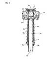
- FIG. 3is a perspective view of the obturator of FIG. 1 ;
- FIG. 4is a cross-sectional view of the access device of FIG. 1 with the cannula in the insertion configuration
- FIG. 5is a cross-sectional view of the access device of FIG. 1 with the cannula in the deployed configuration
- FIG. 6is a partial cross-sectional view of another embodiment of a surgical access device
- FIG. 7Ais a perspective view of cannula of the access device of FIG. 6 in a deployed configuration
- FIG. 7Bis a perspective view of the access device of FIG. 6 with the cannula in an insertion configuration
- FIG. 7Cis a perspective view of the access device of FIG. 6 extending through a body wall with the cannula in an insertion configuration
- FIG. 7Dis a perspective view of the access device of FIG. 7C with the cannula moved to a deployed configuration
- FIG. 7Eis a perspective view of the cannula of the access device of FIG. 7D engaged with the body wall in a deployed configuration.
- the various surgical access devicescan include a housing configured to be at least partially disposed outside a patient's body and an elongate tubular member such as a cannula, wound protector, retractor, or other member for forming a pathway through tissue (hereinafter generally referred to as a cannula).
- the cannulacan extend distally from the housing and it can be configured to be positioned within an opening in a patient's body, such as through skin.
- One or more surgical instrumentscan be inserted through the housing and the cannula to access a surgical site within the body.
- the access devices described hereincan be configured to move between an insertion configuration and a deployed configuration following penetration of the body wall to help securely position the device within the tissue and/or to provide active retraction of the opening formed in the tissue. All or a portion of the cannula can radially expand when the access device is moved from the insertion configuration to the deployed configuration. Such secure positioning can help form a better seal between the tissue and the device and it can help retain the device in a more stable position relative to the tissue.
- the devicecan also optionally dilate the tissue when positioned therein to help improve the seal integrity between the device and the tissue. Such dilation of the tissue by the device can increase a size and/or change the shape of the opening in the tissue to increase working space available through the tissue opening.
- Having more working space through the tissuecan help reduce interference between multiple surgical instruments inserted therethrough and/or allow larger and/or a greater number of surgical instruments to be inserted therethrough.
- the configuration of the surgical access devicescan allow for use with a variety of tissue thicknesses and can reduce the extension of the surgical access devices into the body cavity where the surgical access devices could harm structures within the body cavity and/or interfere with instruments performing a surgical procedure.
- FIGS. 1-5illustrate one exemplary embodiment of an access device.
- the access device 10generally includes a housing 20 having a cannula 40 extending distally therefrom, and an obturator 80 disposable through the housing 20 and cannula 40 .
- the housing 20 and the cannula 40can define a working channel extending through the access device 10 for slidably and removably receiving the obturator 80 and/or any number of other surgical instruments therein.
- a distal tip 82 of the obturator 80can extend through and beyond a distal end of the cannula 40 to penetrate the body wall and to aid in inserting the cannula 40 through tissue.
- the cannula 40can be configured to transition from an insertion configuration, as shown in FIG. 1 , to a deployed configuration, as shown in FIG. 2 , to securely position the access device within the tissue. While any portion of the cannula 40 can change when the cannula 40 is moved between the insertion and deployed configurations, in an exemplary embodiment the cannula 40 includes a distal anchoring element 46 that expands radially outward when the cannula is moved from the insertion configuration to the deployed configuration.
- the access device 10can also include an engagement feature for locking the obturator 80 and the cannula 40 in a fixed position relative to one another.
- the access device 10can also include any number of other features including, by way of non-limiting example, an insufflation port 12 , one or more seal elements 14 , and an actuation mechanism as will be discussed below.
- the housing 20can have a variety of sizes, shapes, and configurations. Generally, the housing can be configured to be positioned external to the patient's body cavity and it can be configured to provide a pathway for receiving a surgical instrument. A distal surface of the housing can be configured to rest on or engage the exterior surface of a body wall to prevent the access device from being pushed into the body cavity. Although not shown, one skilled in the art will appreciate that the housing can include any number of features to facilitate securely engaging the housing to the exterior surface of the body wall such as, by way of non-limiting example, surface features formed on the distal surface of the housing or suture anchors coupled to the housing to aid in securing the housing to the body wall.
- the housingcan include zero, one, or multiple seal elements to receive one or more instruments extending through the working channel.
- Exemplary housing configurationsare described in more detail in U.S. Pat. No. 6,017,356 entitled “Method For Using A Trocar For Penetration And Skin Incision”, issued on Jan. 25, 2000, U.S. Patent Publication No. 2004/0230161 entitled “Trocar Seal Assembly,” filed on Mar. 31, 2004, and in U.S. Patent Publication No. 2007/0185453 entitled “Conical Trocar Seal,” filed on Oct. 15, 2003, which are hereby incorporated by reference in their entireties.
- the housing 20is generally in the form of an annular disc having a central opening 22 , a proximal surface 20 p , and a distal surface 20 d .
- the proximal surface 20 pcan be configured to engage an obturator.
- the proximal surface 20 p of the housing 20can include any coupling mechanism known in the art (e.g., snap rings, bores, etc.) to allow the housing 20 to removably couple to an obturator.
- One or more seal elements 14can be disposed across the working channel of the housing 20 .
- the cannulacan have a variety of sizes, shapes, and configurations. Generally, the cannula extends distally from the housing and is positionable within an opening in a patient's body, whether through a natural opening or a surgical incision. By way of non-limiting example, the cannula can be inserted through the umbilicus.
- the cannulacan be integral with or fixedly or removably coupled to the housing in any manner known in the art (e.g., welded, snap-fit, threads, ball and socket elements, male-female couplings, etc.).
- a distal portion of the cannulacan extend into a body cavity, for example within the abdominal cavity, while a proximal portion of the cannula is positioned within the tissue opening.
- a lumen in the cannulacan define a working channel and form a pathway through the opening so that surgical instruments can be inserted from outside the body through the housing and cannula and into an interior body cavity.
- the cannulacan be substantially flexible so that it can be easily maneuvered into and within tissue as needed.
- the cannulacan be substantially rigid or substantially semi-rigid.
- the cannulacan be formed of any suitable material known in the art, e.g., silicone, urethane, thermoplastic elastomer, and rubber.
- the cannulacan include any number of additional features to facilitate providing access through a body wall. Although the cannula need not include any seal elements, one or more seal elements can be disposed across the working channel of the cannula to seal one or more instruments extending therethrough.
- the cannulais movable between an insertion configuration for insertion through tissue, and a deployed configuration for anchoring within the tissue.
- the cannulacan have an elongated configuration in the insertion position in which a maximum outer diameter of the cannula is reduced to ease insertion through a body wall, and it can have a radially expanded and/or axially contracted configuration in the deployed position to aid in the retention of the access device within the tissue opening and/or to reduce the length of the cannula extending into the body cavity.
- the cannulahas a length in the insertion configuration that is greater than the length of the cannula in the deployed configuration, and/or the cannula has a maximum outer diameter in the insertion configuration that is less than the maximum outer diameter of the cannula in the deployed configuration.
- the cannulacan also be configured to have a biased configuration.
- the cannulacan be biased to the insertion configuration such that a proximally-directed force is required to transition the cannula to the deployed configuration.
- the cannulais biased to the deployed configuration such that a distally-directed force is required to maintain the cannula in the insertion configuration.
- the distal portion of the cannulacan act as an anchor to engage the interior surface of the tissue wall.
- the anchorcan help securely retain the access device within the tissue opening and prevent the access device from being accidentally removed during surgery.
- the distal portion of the cannulacan have a variety of sizes, shapes, and configurations but generally has a maximum outer diameter that is greater than a maximum outer diameter of the proximal portion of the cannula when the cannula is in the deployed configuration.
- Exemplary embodiments of cannula anchorsare described in more detail in U.S. patent application Ser. No. 12/636,174 entitled “Methods and Devices for Providing Access Through Tissue to a Surgical Site,” filed Dec. 11, 2009, and in U.S. patent application Ser. No. 12/636,205 entitled “Methods And Devices For Providing Access Through Tissue To A Surgical Site,” filed Dec. 11, 2009, which are hereby incorporated by reference in their entireties.
- the cannula 40extends distally from the housing 20 and defines a working channel 42 for passage of a surgical instrument.
- the cannula 40can include a telescoping inner tube 48 a , an outer tube 48 b that slidably receives the inner tube 48 a , and an elastically-deformable outer sleeve 44 .
- the telescoping inner tube 48 acan be axially movable relative to the outer tube 48 b .
- the proximal end of the outer tube 48 bcan extend from or be coupled to the housing 20 and the distal end of the inner tube 48 a can extend from or be coupled to the distal end of the outer sleeve 44 .
- the inner tube 48 acan be freely slidable relative to the outer tube 48 b .
- the inner tube 48 acan alternatively be coupled to or extend from the housing, and the outer tube 48 b can be coupled to the distal end of the sleeve 44 , and be freely slidable relative to the inner tube 48 a.
- the outer sleeve 44can have a substantially cylindrical shape in the insertion configuration, as shown in FIGS. 1 and 4 , and a radially-expanded, outwardly tapering shape in the deployed configuration, as shown in FIGS. 2 and 5 .
- the distal portion of the outer sleeve 44can radially expand to form an anchor 46 a for securing the access device 10 against the interior surface of the body wall.
- the surface of the outer sleeve 44can also include a plurality of additional surface features 46 b , 46 c to aid in the retention of the cannula 40 within the tissue opening and to prevent movement of the cannula 40 in the proximal direction when the cannula 40 is in the deployed configuration.
- the sleeve 44can be configured to be biased as shown in FIG. 5 , such that the sleeve 44 in a resting configuration has a longitudinally contracted and radially expanded configuration, with the inner tube 48 a withdrawn into the outer tube 48 b .
- the cannula 40can be transitioned to the insertion configuration, as shown in FIG. 4 , with a distally-directed force on the distal end of cannula 40 , thereby longitudinally extending the deformable sleeve 44 and sliding the inner tube 48 a distally relative to the outer tube 48 b .
- the sleeve 44can be formed from a variety of materials known in the art, including for example various plastics, silicone, polyisoprene, other elastomers or rubbers, and/or any combination thereof.
- the material or materials chosen for the sleeve 44can have a combination of optimal attributes such as flexibility, strength, durability, breathability, microbial resistance, etc.
- the sleeve 44can be formed as a mesh or an impermeable sheath.
- the obturatorcan also have a variety of shapes, sizes, and configurations.
- the obturatorcan include an elongate shaft having a proximal handle configured to be disposed outside a patient's body and a distal end with a tip configured to be inserted through tissue.
- the obturatorcan be a solid member or it can be substantially hollow.
- the shaft of the obturatorcan be substantially flexible or rigid.
- the shaftcan be formed from a flexible material, and/or it can include one or more features formed therein to facilitate flexibility, such as a plurality of cut-outs or slots.
- the shaftcan also include regions that vary in flexibility.
- Varying flexibility of the shaftcan be achieved in a variety of ways as will be appreciated by a person skilled in the art, such as by forming the shaft from different materials, varying the diameter or thickness of the shaft, etc.
- the shaftcan also include other features to facilitate use, such as one or more spiral wires embedded therein and configured to preventing kinking of the shaft.
- the size and shape of the obturatorcan vary, but as shown in one exemplary embodiment depicted in FIGS. 1-3 , the shaft 86 of the obturator 80 can have a longitudinal length greater than a longitudinal length of the access device 10 in the insertion configuration such that the obturator 80 can be inserted through the working channel with the handle 88 located just proximal to the housing 20 and the distal tip 82 located distal to the distal end of the cannula 40 .
- the handle 88can have a maximum diameter greater than a diameter of at least a proximal-most opening in the working channel of the housing 20 , thereby preventing the handle 88 from passing through the housing 20 .
- the obturator 80can be configured to rotate about its longitudinal access, but it can also be selectively fixed relative to the housing 20 and cannula 40 such that rotation of the obturator 80 causes corresponding rotation of the housing 20 and cannula 40 .
- the distal tip 82 of the obturator 80can have a variety of shapes, sizes, and configurations. Generally, the tip 82 can be configured to penetrate tissue. The tip 82 can be formed from one or more flexible and/or rigid materials, such as stainless steel, titanium, etc., to help the tip 82 penetrate tissue. In an exemplary embodiment, the obturator 80 can be hollow and the tip 82 can be transparent to allow visualization therethrough. By way of non-limiting example, an endoscope (not shown) can be proximally inserted into the obturator 80 to provide visualization through a transparent distal tip 82 . The tip 82 can have a variety of shapes and sizes, e.g., conical (as shown in FIG.
- the tip 82can be integrally formed with the shaft 86 , or can be removably or fixedly attached to the shaft 86 , e.g., through an interference fit, an adhesive, ultrasonic welding, etc.
- the tip 82can also be set substantially off-center of the longitudinal axis of the shaft 86 such that the tip 82 is self-tapping to ease insertion and minimize damage to the tissue.
- the tip 82can include one or more features to help penetrate tissue, e.g., tissue-separators, a tapered shape, a beveled edge (including a chamfered edge), a pointed needle, an electronic cutter, a sharp cutting blade, etc.
- the tip 82can include one or more tissue-separating wings that extend radially outward from the tip 82 to assist in moving the tip 82 through tissue and to help minimize damage to the tissue.
- Exemplary configurations for the tip 82are described in U.S. Patent Application No. 2007/0260121 entitled “Endoscopic Translumenal Surgical Systems,” filed May 8, 2006, U.S. patent application Ser. No. 12/478,882 entitled “Multiplanar Obturator with Foldable Retractor,” filed Jun. 5, 2009, and U.S. Patent Application No. 2007/0260273 entitled “Endoscopic Translumenal Surgical Systems,” filed May 8, 2006, which are hereby incorporated by reference in their entireties.
- the distal end of the cannulacan include one or more engagement features formed thereon or coupled thereto for releasably mating with one or more complementary engagement features formed on an obturator. As shown in FIGS. 1-5 , the distal end of the obturator 80 can be configured to engage the distal end of the cannula 40 .
- the obturator 80includes a protrusion 84 extending radially outward from an outer perimeter of the obturator 80 , e.g., from an outer sidewall of the obturator 80 , and at least one corresponding opening 50 is formed in the distal end of the cannula 40 .
- the opening 50can include a longitudinally-extending portion in which the protrusion 84 can be inserted into and/or removed from the opening 50 in a proximal-distal direction, and a radially-extending portion in which the protrusion 84 can laterally slide to lock and unlock the protrusion in the opening.
- the protrusion 84 and opening 50can have any shape and size that allow the protrusion 84 to be inserted into the longitudinal portion of the opening 50 and to slide within the circumferential portion of the opening 50 .
- the obturator 80with the cannula 40 keyed thereto through engagement of the protrusion 84 and the opening 50 , can be rotated in a first direction, e.g., a clockwise direction, relative to the cannula 40 , thereby causing the protrusion 84 to travel laterally within the opening 50 to a position in which the protrusion 84 abuts the terminal end of the circumferential portion of the opening 50 , thereby locking the distal end of the obturator 80 to the cannula 40 .
- a first directione.g., a clockwise direction
- the opening 50can angle proximally or distally (not shown) at its terminal end such that the protrusion 84 can proximally or distally slide and snap into the terminal end to help ensure that the protrusion 84 is fully engaged with the opening 50 .
- the protrusion 84can move in only one direction (e.g., clockwise) to lock the obturator 80 to the cannula 40 because the circumferential portion of the opening 50 extends in a single direction from the longitudinal portion of the opening 50 .
- the longitudinal portion of the opening 50extends proximally from the circumferential portion such that the protrusion 84 can be removed proximally from the opening 50 formed in the distal end of the cannula 40 when the protrusion 84 is longitudinally aligned with the longitudinal portion of the opening 50 .
- the circumferential portion of the opening 50can extend in both directions from the longitudinal portion of the opening 50 such that rotation of the obturator 80 in either direction (i.e., clockwise or counter-clockwise) can be effective to lock the obturator 80 relative to the distal end of the cannula 40 .
- the surgical access device 10can provide access to a patient's body cavity.
- the cannula 40is positionable within an opening in a patient's body such that a distal portion of the cannula 40 extends into a patient's body cavity and a proximal portion of the cannula is positioned within the tissue opening.
- a lumen in the cannula 40can define a working channel and form a pathway through the opening in a patient's body so that surgical instruments can be inserted from outside the body to an interior body cavity.
- the obturator 80Prior to insertion of the access device 10 through a patient's body wall, and with the cannula 40 biased in the deployed configuration, as shown in FIG. 2 , the obturator 80 can be inserted into the working channel of the housing 20 and cannula 40 such that the distal end of the obturator 80 engages the distal end of the cannula 40 .
- the distal end of the obturatorcan be keyed to the distal end of the cannula 40 through the coupling of the complementary engagement features of the distal ends of the obturator 80 and cannula 40 .
- the protrusion 84may be aligned with and inserted into the longitudinal portion of the opening 50 , and the obturator 80 can be rotated relative to the cannula 40 such that the protrusion 84 slides along the circumferential portion of the opening 50 to fully engage the complementary engagement mechanisms. Subsequent distal extension of the obturator 80 relative to the housing 20 can be effective to transition the cannula 40 from the deployed configuration to the insertion configuration.
- the obturator housingcan include a latch or other feature that engages a corresponding feature formed on the housing of the cannula to thereby lock the obturator within the cannula when the obturator is fully deployed into the cannula and the cannula is in the insertion configuration.
- the cannula 40can be inserted through a natural opening, a surgical incision, or can be configured to penetrate the body wall.
- the surgeoncan pierce the body wall with the obturator tip 82 and provide a distally-directed force to force the cannula 40 through the body wall.
- rotation of the obturator 80can be effective to aid in penetrating the cannula 40 through the body wall and into the body cavity.
- the keying of the distal end of the cannula 40 to the obturator 80can lock the two components together causing the cannula 40 and obturator 80 to rotate as a unit. That is, the obturator 80 and the cannula 40 are fixed relative to one another when the complementary engagement features are mated such that rotation of the obturator 80 can be effective to cause corresponding rotation of the cannula 40 .
- the cannula 40can be transitioned from the insertion configuration to the deployed configuration.
- the obturator 80can be pulled distally relative to the cannula 40 to cause or allow the expandable sleeve 44 to revert to its biased configuration, thereby withdrawing the inner tube 48 a within the outer tube 48 b and expanding the distal anchoring element 46 .
- the distal end of the cannula 40is pulled toward the proximal end of the cannula 40 , causing the expandable sleeve 44 to decrease in length and causing the distal anchoring element 46 to expand radially outward and engage the interior surface of the body wall to lock the access device within the tissue wall. Expansion can occur as a result of the folding or accordion-type configuration of the sidewalls of the sleeve 44 .
- the obturator 80can then be rotated to un-key the obturator from the cannula 40 .
- the obturator 80can be rotated to align the protrusion 84 with the longitudinal portion of the opening 50 such that the obturator 80 can be pulled proximally to disengage the protrusion 84 from the opening 50 and to remove the obturator 80 from the access device 10 .
- Various tools/instrumentscan then be inserted through the cannula 40 .
- the obturator 80can be reinserted into the cannula 40 , rotated to cause the engagement mechanisms to mate, and then moved further distally within the cannula to cause the cannula to move to the insertion configuration.
- the access device 10can then be removed from the tissue wall.
- the obturator 80can be operatively associated with an actuation mechanism that is effective to transition the cannula 40 between the insertion configuration to the deployed configuration.
- the access device 210is similar to access device 10 and generally includes a housing 220 and a cannula 240 extending distally from the housing 220 .
- the housing 220 and the cannula 240can define a working channel extending through the access device 210 .
- the distal portion of the cannula 240can include an expandable anchor 246 that is configured to transition from an insertion configuration, as shown in FIG. 7B , to a deployed configuration as shown in FIG. 7A .
- the access device 210can also include an obturator 280 .
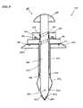
- the obturator 280has an inner tube 286 and an outer tube 292 with a proximal head 290 formed thereon.
- the obturator 280also includes a rotatable actuation mechanism 260 operatively associated with the inner and outer tubes 286 , 292 and effective to move the inner tube 286 relative to the outer tube 292 to cause the expandable anchor 246 to expand.
- the housing 220can be configured to be positioned external to the patient's body cavity and can have a variety of shapes, sizes, and configurations.
- the housing 220is generally in the form of an annular disc having a central opening 222 , a proximal surface 220 p , and a distal surface 220 d .
- the distal surface 220 d of the housing 220can be configured to rest on or engage the exterior surface of a body wall when the access device 210 is positioned within a tissue opening.
- the proximal surface 220 pcan be configured to engage an obturator 280 and can include any variety of coupling mechanisms known in the art to allow the housing 220 to removably couple to the obturator 280 .
- the proximal surface 220 pcan include a plurality of bores 224 for receiving latches or pins 297 extending distally from the head 290 of the obturator 280 .
- the cannula 240extends distally from the housing 220 and can provide a working channel through a tissue opening.
- the distal portion of the cannula 240includes an expandable anchor 246 and an annular member 254 having a keying element for coupling to a complementary keying element of the obturator 280 .
- the anchor 246can generally be configured to transition from an insertion configuration in which the anchor 246 has a first outer diameter to a deployed configuration in which the anchor 246 has a second outer diameter that is greater than the first outer diameter.
- the expandable anchor 246preferably has a diameter that is the same as the diameter of the proximal portion of the cannula 240 , and in the deployed configuration, the expandable anchor 246 can have a diameter greater than the diameter of the proximal portion of the cannula 240 .
- the anchor 246can have virtually any configuration.
- the anchor 246can be in the form of, for example, a plurality of flexible cables, strings, threads, bands, ribbons, strips, or wires, generally referred to as “wires”, spaced apart from one another and configured to longitudinally collapse and radially expand when the anchor 246 moves from the insertion configuration to the deployed configuration.
- a protective sleevecan be disposed around the anchor 246 to protect the wires and prevent the wires from snagging on tissue or other matter.
- the protective sleevecan optionally include gripping features (not shown), e.g., a textured surface, a non-slip coating, etc., configured to help grip tissue and reduce slippage of the anchor 246 when the anchor 246 is deployed and abuts the interior surface of the body wall.
- the cannula 240can include an annular shoulder 256 formed on an inner surface thereof for engaging the distal end of the outer tube 292 of the obturator 280 . The annular shoulder 256 can be located, for example, just proximal to the anchor 246 .
- the obturator 280which can be disposed in the working channel defined by the housing 220 and the cannula 240 , generally includes an outer tube 292 and inner tube 286 .
- the inner tube 286is generally an elongate member and can include a proximal handle 288 and a distal tip 282 .
- a keying elementcan be formed on the distal portion of the inner tube 286 for engagement with a corresponding keying element on the distal end of the cannula 240 , and in particular on the distal end of the anchor 246 of the cannula 240 .
- a protrusion 284can extend radially outward from the distal portion of the inner tube 286 for keying with an opening 250 formed in the annular member 254 .
- the tip 282can also include various features as previously described with respect to tip 82 .
- tip 282can include one or more tissue-separating wings 283 a , 283 b that extend radially outward from the tip 282 to assist in moving the tip 282 through tissue and to help minimize damage to the tissue.
- the tip 282can also in other embodiments be transparent to allow viewing through the tip 282 , e.g., with an endoscope.
- the inner tube 286can have a sufficient longitudinal length such that, when the cannula 240 is in the insertion configuration, the inner tube 286 can be disposed through the lumen of the outer tube 292 and through the working channel of the housing 220 and cannula 240 with the handle 288 located proximal to the housing 220 and the distal tip 282 located distal to the distal end of the cannula 240 .
- At least a portion of the inner tube 286can include a groove or guide channel 296 formed on an outer surface thereof for threadingly receiving a detent 262 of the rotatable knob 260 , as will be discussed in more detail below.
- the guide channel 296extends radially around an outer surface of the inner tube 286 at an angle relative to a longitudinal axis of the inner tube 286 .
- the guide channel 296can have any length, for example, it can extend 30 degrees, 60 degrees, 90 degrees, etc. around the inner tube 286 .
- the length of the guide channel 296preferably corresponds to the distance that the outer tube 292 needs to move relative to the inner tube 286 to cause expansion of the distal anchor.
- the terminal ends of the guide channel 296can include a stop feature for preventing further rotational movement of the detent 262 along the guide channel 296 and for frictionally engaging the detent 262 to maintain the detent 262 therein by interference fit, thereby maintaining the inner and outer tubes in a fixed axial position relative to one another.
- a dimple (not shown) formed in the proximal terminal end of the guide channel 296can engage the detent 262 such that further motion of the inner tube 286 relative to the outer tube 292 can be restricted.
- a dimple (not shown) formed in the distal terminal end of the guide channel 296can engage the detent 262 such that further motion of the inner tube 286 relative to the outer tube 292 can be restricted.
- the inner tube 286can alternatively include a detent or raised threads and the rotatable knob 260 could include a corresponding guide channel or complementary threads for axially translating the inner member 286 with rotation of the rotatable knob 260 .
- the outer tube 292is configured to be disposed within the working channel defined by the housing 220 and the cannula 240 , and it can be a generally cylindrical member having a lumen formed therein.
- the distal end of the outer tube 292can include an engagement feature for engaging the annular shoulder 256 of the cannula 240 .
- a grommet 298can be disposed around an outer surface of the distal portion of the outer tube 292 for forming an interference or friction fit with the annular shoulder 256 .
- the outer tube 292can also include a proximal head 290 that is configured to engage a proximal surface 220 p of the housing 220 . As shown in FIG.
- the head 290includes a snap ring 294 extending proximally from its proximal surface 290 p that is configured to be received within an annular recess 264 formed within a distal surface of the rotatable knob 260 such that the rotatable knob 262 can be freely rotated relative to the outer tube 292 .
- the distal surface 290 d of the headcan include an engagement mechanism for removably coupling the obturator 280 to the housing 220 .
- pins 297can extend distally from the distal surface 290 d of the head to removably engage bores 224 formed in the proximal surface 220 p of the housing 220 by compression fit, snap-fit, etc.
- the actuation mechanismcan also have a variety of shapes, sizes, and configurations.
- the actuation mechanismis operatively associated with the obturator and can be effective to move the cannula from the insertion configuration to the deployed configuration when the obturator is disposed within the cannula.
- the actuation mechanismcan be a rotatable knob 260 freely rotatably coupled to the proximal surface of the head 290 of the outer tube 292 and in engagement with the inner tube 286 .
- the rotatable knob 260can be generally shaped as an annular disc having a proximal surface, a distal surface, and an inner wall defining a central opening through which the inner tube 286 can be disposed.
- the distal surface of the rotatable knob 260can include an annular recess 264 configured to receive the snap ring 294 formed on the proximal surface of the head 290 of the outer tube 292 , as discussed above, such that the rotatable knob 260 is freely rotatable relative to the head 290 and outer tube 292 .
- the rotatable knob 260also includes a detent 262 that extends radially inward from the inner wall of the rotatable knob 260 .
- the detent 262can be configured to extend into and engage the guide channel 296 formed in the inner tube 286 of the obturator such that rotation of the knob 260 is effective to axially translate the inner member 286 in a proximal/distal direction relative to the outer member 290 as the detent 262 moves through the guide channel 296 .
- the rotatable knob 260can include additional features (e.g., rotation locks) to selectively restrict the rotatable knob 260 from rotating relative to the obturator 280 .
- FIG. 7Aillustrates the access device 210 with the anchor 246 biased in the deployed configuration, prior to the inserting the obturator 280 through the cannula.
- the obturator 280is inserted into the cannula 240 , as shown in FIG. 7B , the inner tube 286 and outer tube 292 will extend through the working channel.
- the head 290 on the outer tube 292can be advanced into engagement with the housing 220 , e.g., through engagement of the pins 297 with the bores 224 .
- the grommet 298 at the distal end of the outer tube 292will engage the annular shoulder 256 of the cannula 240 to stretch the cannula distally, thereby moving the cannula into the insertion configuration, as shown in FIG. 7B .
- the inner tube 286can similarly move the distal anchor into the insertion configuration.
- the engagement feature 284 on the distal end of the inner tube 286can engage the engagement feature 250 formed in the annular member 254 . In this position, the distal tip 282 of the inner tube 292 will extend beyond the distal end of the cannula 240 .
- the inner tube 286can optionally be rotated to key the corresponding engagement features 250 , 284 .
- the cannula 240can be inserted through a natural opening, penetrated through tissue, or inserted through a surgical incision.
- the surgeoncan pierce the body wall with the distal tip 282 of the inner tube 286 and provide a distally-directed force to the access device 210 to force the cannula 240 through the body wall.
- rotation of the head 290 on the outer tube 292can also be effective to cause corresponding rotation of the cannula 240 to facilitate insertion through the body wall and into the body cavity.
- the keying of the distal end of the inner tube 286 of the obturator 280 to the cannula 240can prevent independent rotation of the cannula 240 .
- the anchor 240When the housing 220 is seated on the exterior surface of the body wall, the anchor 240 can be transitioned from the insertion configuration to the deployed configuration. As shown in FIG. 9 , rotation of the rotatable knob 260 about the proximal end of the outer tube 292 can be effective to axially move the inner tube 286 in a proximal direction relative to the outer tube 292 . As a result, the distal end of the anchor 246 is moved proximally toward the proximal end of the anchor 246 , thereby causing the anchor to collapse radially outward into its deployed configuration as shown in FIG. 7D .
- the distal end of the inner tube 286can be disengaged from the distal end of the cannula 240 .
- the handle 288can be rotated to disengage the engagement feature 284 on the inner tube 286 from the engagement feature 250 on the cannula 240 .
- the engagement of the grommet 298 on the outer tube 292 with the annular shoulder 256 on the cannula 240can be effective to retain the cannula 240 in an axially extended configuration.
- the obturator 280can be used to deploy the anchor 246 while the obturator is still fully disposed within the cannula 240 , and thus without the need to remove the obturator from the cannula. Such a configuration will ensure engagement of the inner wall of the tissue by the anchor before removal of the obturator.
- the head 290 of the outer tube 292can be pulled proximally to disengage the pins 297 from the bores 224 .
- the entire anchor 246can move proximally toward the housing 220 , resulting in axial compression or contraction of the cannula 240 , as shown in FIG. 7E .
- the anchor 246is thus pulled into further engagement with the interior surface of the body wall, thus capturing the tissue wall between the anchor 246 and the housing 220 .
- the cannula and/or anchorcan return to its insertion configuration to ease removal of the access device following completion of the surgical procedure.
- the access devicecan be prepared for removal by re-engaging the obturator with the distal end of the cannula (e.g., re-keying the complementary engagement features).
- the obturatorcan then be extended distally such that distal end of the cannula 40 extends distally and assumes its insertion configuration.
- the housing and obturatorcan then be pulled proximally to remove the access device 10 from the tissue opening.
- a separate removal devicecan also be provided to remove the access device.
- the housing, cannula, actuation mechanism, and obturatorcan be formed from a variety of materials known in the art, including but not limited to various polymers, including polycarbonates and polyetheretherketone (PEEK), metals such as titanium or stainless steel, composites such as carbon-fiber reinforced PEEK, various ceramic materials, and/or any combination thereof.
- various polymersincluding polycarbonates and polyetheretherketone (PEEK), metals such as titanium or stainless steel, composites such as carbon-fiber reinforced PEEK, various ceramic materials, and/or any combination thereof.
- These structurescan also be formed of various semi-rigid/flexible materials, including polyurethanes such as Pellethane (available from The Dow Chemical Company of Midland, Mich., USA), thermoplastic elastomers such as Santoprene (available from ExxonMobil Chemical of Houston, Tex., USA), polyisoprene elastomers, medium to high durometer silicone elastomers, and/or any combination thereof.
- polyurethanessuch as Pellethane (available from The Dow Chemical Company of Midland, Mich., USA)
- thermoplastic elastomerssuch as Santoprene (available from ExxonMobil Chemical of Houston, Tex., USA)
- polyisoprene elastomerssuch as Teryrenelastomers
- medium to high durometer silicone elastomersand/or any combination thereof.
- any other suitable materialsuch as fabrics, foams, plastics, and/or metals, can be used to form the structures and devices disclosed herein and that each of the structures and devices
- an exemplary surgical access device kitcould include multiple housings, cannulas, and actuation mechanisms.
- an engagement and/or release mechanismcan be included to allow certain components of the surgical access device to be removable as needed.
- Any engagement and release mechanism known in the arte.g., a snap-lock mechanism, corresponding threads, etc., can be used to releasably mate components of the device. Exemplary embodiments of an engagement and release mechanisms are described in more detail in U.S. patent application Ser. No. 12/242,765 entitled “Surgical Access Device” filed on Sep.
- a component of the devicesuch as a seal, housing, cannula, etc.
- a component of the devicecan have one or more lights formed thereon or around a circumference thereof to enable better visualization when inserted within a patient.
- any wavelength of lightcan be used for various applications, whether visible or invisible.
- Any portion of the access devicecan also be opaque, semi-transparent, or optically clear.
- the distal tip of the obturatorcan be optically clear such that a scope inserted into a hollow obturator can provide visualization through the transparent tip.
- the obturator tipcan include one or more features to help penetrate tissue, e.g., tissue-separators, a tapered shape, a beveled edge (including a chamfered edge), a pointed needle, an electronic cutter, a sharp cutting blade, etc.
- the tipcan include one or more tissue-separating wings which extend radially outward from the tip and converge to a lateral edge to assist in moving the tip through tissue and to help minimize damage to the tissue. Exemplary tip configurations are discussed in U.S. Patent Application No. 2007/0260121 entitled “Endoscopic Translumenal Surgical Systems,” filed May 8, 2006, which is hereby incorporated by reference in its entirety.
- any number of portscan also be included on and/or through the surgical access devices to enable the use of various surgical techniques and devices as needed in a particular procedure.
- openings and portscan allow for the introduction of pressurized gases, vacuum systems, energy sources such as radiofrequency and ultrasound, irrigation, imaging, etc.
- energy sourcessuch as radiofrequency and ultrasound, irrigation, imaging, etc.
- any of these techniques and devicescan be removably attachable to the surgical access device and can be exchanged and manipulated as needed.
- insufflation fluidis provided through an access device to expand the body cavity to facilitate the surgical procedure.
- Any and all of the surgical access devices described hereincan also include various other features, such as one or more ventilation ports to allow evacuation of smoke during procedures that utilize cautery, and/or one or more insufflation ports through which the surgeon can insufflate the abdomen to cause pneumoperitenium, as described by way of non-limiting example in U.S. Patent Application No. 2006/0247673 entitled “Multi-port Laparoscopic Access Device” filed Nov. 2, 2006, which is hereby incorporated by reference in its entirety.
- the insufflation portcan be located anywhere on the device, can have any size, and can accept a leur lock or a needle, as will be appreciated by those skilled in the art.
- the access devices disclosed hereincan include at least one seal element.
- seal elementsare known in the art, but typically the surgical access device can include at least one instrument seal that forms a seal around an instrument disposed therethrough, but otherwise does not form a seal when no instrument is disposed therethrough; at least one channel seal or zero-closure seal that seals the working channel created by the sealing port when no instrument is disposed therethrough; or a combination instrument seal and channel seal that is effective to both form a seal around an instrument disposed therethrough and to form a seal in the working channel when no instrument is disposed therethrough.
- seals known in the artcan be used including, e.g., duckbill seals, cone seals, flapper valves, gel seals, diaphragm seals, lip seals, iris seals, etc.
- seal elementscan be disposed at various locations within the access devices described herein, by way of non-limiting example, positioned within sealing ports formed in the housing and/or the cannula. Seal elements can be formed integrally with the housing or cannula or can be selectively coupled thereto using a variety of means known in the art.
- the seal elementscan be fixed relative to the housing and/or cannula or can be rotatable or movable.
- the seal elements used in the surgical access devicecan also be removable, replaceable, and interchangeable.
- Exemplary instrument seal configurationsare described in more detail in U.S. patent application Ser. No. 12/399,482 entitled “Methods And Devices For Providing Access Into A Body Cavity,” filed Mar. 6, 2009, U.S. Patent Publication No. 2004/0230161 entitled “Trocar Seal Assembly,” filed on Mar. 31, 2004, and U.S. Patent Publication No. 2007/0185453 entitled “Conical Trocar Seal,” filed on Oct. 15, 2003, which are hereby incorporated by reference in their entireties.
- Zero-closure sealscan also include various other features, as described in more detail in U.S. Patent Publication No. 2009/0005799, entitled “Duckbill Seal with Fluid Drainage Feature,” filed on Jun. 29, 2007, and U.S. Pat. No. 5,330,437, entitled “Self Sealing Flexible Elastomeric Valve and Trocar Assembly for Incorporating Same,” filed Nov. 12, 1993, which are hereby incorporated by reference in their entirety.
- a surgical access devicecan also include one or more safety shields positioned through, in, and around any of the components and/or tissue to protect the components against puncture or tear by surgical instruments being inserted through the device.
- safety shieldsare described in more detail in U.S. Patent Publication No. 2006/0247673 entitled “Multi-port Laparoscopic Access Device” filed Nov. 2, 2006, U.S. patent application Ser. No. 12/399,625 entitled “Methods and Devices for Providing Access to a Body Cavity” filed on Mar. 6, 2009, U.S. patent application Ser. No. 12/399,482 entitled “Methods and Devices for Providing Access to a Body Cavity” filed on Mar.
- any of the embodiments described hereincan be used in performing a sleeve gastrectomy and/or a gastroplasty, as described in U.S. application Ser. No. 12/242,765 entitled “Surgical Access Device” filed on Sep. 30, 2008; U.S. application Ser. No. 12/242,711 entitled “Surgical Access Device with Protective Element” filed on Sep. 30, 2008; U.S. application Ser. No.
- the devices disclosed hereincan be designed to be disposed of after a single use, or they can be designed to be used multiple times. In either case, however, the device can be reconditioned for reuse after at least one use. Reconditioning can include any combination of the steps of disassembly of the device, followed by cleaning or replacement of particular pieces, and subsequent reassembly.
- the devicecan be disassembled, and any number of the particular pieces or parts of the device can be selectively replaced or removed in any combination, e.g., seal, housing, cannula, etc.
- the devicecan be reassembled for subsequent use either at a reconditioning facility, or by a surgical team immediately prior to a surgical procedure.
- reconditioning of a devicecan utilize a variety of techniques for disassembly, cleaning/replacement, and reassembly. Use of such techniques, and the resulting reconditioned device, are all within the scope of the present application.
- the invention described hereinwill be processed before surgery.
- a new or used instrumentis obtained and if necessary cleaned.
- the instrumentcan then be sterilized. This can be done by any number of ways known to those skilled in the art including beta or gamma radiation, ethylene oxide, steam, and a liquid bath (e.g., cold soak).
- the instrumentis placed in a closed and sealed container, such as a plastic or TYVEK bag.
- the container and instrumentare then placed in a field of radiation that can penetrate the container, such as gamma radiation, x-rays, or high-energy electrons.
- the radiationkills bacteria on the instrument and in the container.
- the sterilized instrumentcan then be stored in the sterile container.
- the sealed containerkeeps the instrument sterile until it is opened in the medical facility.
Landscapes
- Health & Medical Sciences (AREA)
- Surgery (AREA)
- Life Sciences & Earth Sciences (AREA)
- Biomedical Technology (AREA)
- Nuclear Medicine, Radiotherapy & Molecular Imaging (AREA)
- Engineering & Computer Science (AREA)
- Pathology (AREA)
- Heart & Thoracic Surgery (AREA)
- Medical Informatics (AREA)
- Molecular Biology (AREA)
- Animal Behavior & Ethology (AREA)
- General Health & Medical Sciences (AREA)
- Public Health (AREA)
- Veterinary Medicine (AREA)
- Surgical Instruments (AREA)
Abstract
Description
Claims (19)
Priority Applications (2)
| Application Number | Priority Date | Filing Date | Title |
|---|---|---|---|
| US12/635,990US8435174B2 (en) | 2009-12-11 | 2009-12-11 | Methods and devices for accessing a body cavity |
| PCT/US2010/059633WO2011072102A1 (en) | 2009-12-11 | 2010-12-09 | Methods and devices for accessing a body cavity |
Applications Claiming Priority (1)
| Application Number | Priority Date | Filing Date | Title |
|---|---|---|---|
| US12/635,990US8435174B2 (en) | 2009-12-11 | 2009-12-11 | Methods and devices for accessing a body cavity |
Publications (2)
| Publication Number | Publication Date |
|---|---|
| US20110144440A1 US20110144440A1 (en) | 2011-06-16 |
| US8435174B2true US8435174B2 (en) | 2013-05-07 |
Family
ID=43662267
Family Applications (1)
| Application Number | Title | Priority Date | Filing Date |
|---|---|---|---|
| US12/635,990Expired - Fee RelatedUS8435174B2 (en) | 2009-12-11 | 2009-12-11 | Methods and devices for accessing a body cavity |
Country Status (2)
| Country | Link |
|---|---|
| US (1) | US8435174B2 (en) |
| WO (1) | WO2011072102A1 (en) |
Cited By (41)
| Publication number | Priority date | Publication date | Assignee | Title |
|---|---|---|---|---|
| US20110028791A1 (en)* | 2009-07-28 | 2011-02-03 | Marino James F | Arcuate surgical guidance system and methods |
| US20110172494A1 (en)* | 2010-01-12 | 2011-07-14 | Tedan Surgical | Surgical retractor with curved rotating blades |
| US20140180015A1 (en)* | 2002-10-07 | 2014-06-26 | Apollo Camera, L.L.C. | Trocar cannula anchor and seal |
| US20150327886A1 (en)* | 2011-11-01 | 2015-11-19 | Zhenquan Shen | Method for manufacturing disposable endoscopic puncture outfit for laparoscopy operations and a puncture outfit using the method |
| US9427257B2 (en) | 2014-07-08 | 2016-08-30 | Applied Medical Resources Corporation | Highly responsive instrument seal |
| US9675379B2 (en) | 2013-03-08 | 2017-06-13 | Cannuflow, Inc. | Arthroscopic flexible portal cannula device and delivery system |
| WO2017173231A1 (en)* | 2016-03-31 | 2017-10-05 | Vigor Medical Technologies, Ltd. | Reversibly removable self-adjusting port |
| US9808282B2 (en) | 2015-06-04 | 2017-11-07 | Medos International Sarl | Surgical cannula system and method of use |
| US9924979B2 (en) | 2014-09-09 | 2018-03-27 | Medos International Sarl | Proximal-end securement of a minimally invasive working channel |
| US9980737B2 (en) | 2014-08-04 | 2018-05-29 | Medos International Sarl | Flexible transport auger |
| US10111712B2 (en) | 2014-09-09 | 2018-10-30 | Medos International Sarl | Proximal-end securement of a minimally invasive working channel |
| US10264959B2 (en) | 2014-09-09 | 2019-04-23 | Medos International Sarl | Proximal-end securement of a minimally invasive working channel |
| US10299838B2 (en) | 2016-02-05 | 2019-05-28 | Medos International Sarl | Method and instruments for interbody fusion and posterior fixation through a single incision |
| US10682130B2 (en) | 2015-09-04 | 2020-06-16 | Medos International Sarl | Surgical access port stabilization |
| US10786264B2 (en) | 2015-03-31 | 2020-09-29 | Medos International Sarl | Percutaneous disc clearing device |
| USRE48534E1 (en) | 2012-04-16 | 2021-04-27 | DePuy Synthes Products, Inc. | Detachable dilator blade |
| US11013530B2 (en) | 2019-03-08 | 2021-05-25 | Medos International Sarl | Surface features for device retention |
| US11045324B2 (en) | 2006-12-08 | 2021-06-29 | DePuy Synthes Products, Inc. | Method of implanting a curable implant material |
| US11051862B2 (en) | 2001-11-03 | 2021-07-06 | DePuy Synthes Products, Inc. | Device for straightening and stabilizing the vertebral column |
| US11129727B2 (en) | 2019-03-29 | 2021-09-28 | Medos International Sari | Inflatable non-distracting intervertebral implants and related methods |
| US11134987B2 (en) | 2011-10-27 | 2021-10-05 | DePuy Synthes Products, Inc. | Method and devices for a sub-splenius/supra-levator scapulae surgical access technique |
| US11172957B2 (en) | 2018-02-07 | 2021-11-16 | Stryker Corporation | Surgical cannula and methods of use |
| US11219439B2 (en) | 2012-09-26 | 2022-01-11 | DePuy Synthes Products, Inc. | NIR/RED light for lateral neuroprotection |
| US11241252B2 (en) | 2019-03-22 | 2022-02-08 | Medos International Sarl | Skin foundation access portal |
| US20220110515A1 (en)* | 2020-10-13 | 2022-04-14 | Baylor College Of Medicine | Radially adjustable surgical dilator for remote access surgical procedures |
| US11337603B2 (en)* | 2017-05-08 | 2022-05-24 | Platform Imaging, LLC | Laparoscopic device implantation and fixation system and method |
| US11439380B2 (en) | 2015-09-04 | 2022-09-13 | Medos International Sarl | Surgical instrument connectors and related methods |
| US20220287813A1 (en)* | 2019-08-29 | 2022-09-15 | Selcuklu Veteriner Hayvancilik Ith. Ihra. Tic. San. Ltd. Sti. | Fixable degassing trocar |
| US11559328B2 (en) | 2015-09-04 | 2023-01-24 | Medos International Sarl | Multi-shield spinal access system |
| US11660082B2 (en) | 2011-11-01 | 2023-05-30 | DePuy Synthes Products, Inc. | Dilation system |
| US11672562B2 (en) | 2015-09-04 | 2023-06-13 | Medos International Sarl | Multi-shield spinal access system |
| US20230225759A1 (en)* | 2020-05-01 | 2023-07-20 | Cilag Gmbh International | Balancing feature for reusable trocar |
| US11737743B2 (en) | 2007-10-05 | 2023-08-29 | DePuy Synthes Products, Inc. | Dilation system and method of using the same |
| US11744447B2 (en) | 2015-09-04 | 2023-09-05 | Medos International | Surgical visualization systems and related methods |
| US11771517B2 (en) | 2021-03-12 | 2023-10-03 | Medos International Sarl | Camera position indication systems and methods |
| US11813026B2 (en) | 2019-04-05 | 2023-11-14 | Medos International Sarl | Systems, devices, and methods for providing surgical trajectory guidance |
| WO2024062472A1 (en)* | 2022-09-23 | 2024-03-28 | T.A.G. Medical Products Corporation Ltd. | Trocar including cannula |
| US12035941B2 (en) | 2020-05-01 | 2024-07-16 | Cilag Gmbh International | Airflow channels and patterns in lumen for cannula |
| US12150636B2 (en) | 2015-09-04 | 2024-11-26 | Medos International Sárl | Surgical instrument connectors and related methods |
| US12329410B2 (en) | 2020-08-12 | 2025-06-17 | Mazor Robotics Ltd. | Cannulation devices, systems, and methods |
| US12426868B2 (en) | 2007-09-28 | 2025-09-30 | DePuy Synthes Products, Inc. | Balloon with shape control for spinal procedures |
Families Citing this family (59)
| Publication number | Priority date | Publication date | Assignee | Title |
|---|---|---|---|---|
| US7740641B2 (en) | 2005-04-14 | 2010-06-22 | Ethicon Endo-Surgery, Inc. | Clip applier with migrational resistance features |
| US7297149B2 (en) | 2005-04-14 | 2007-11-20 | Ethicon Endo-Surgery, Inc. | Surgical clip applier methods |
| US7686820B2 (en) | 2005-04-14 | 2010-03-30 | Ethicon Endo-Surgery, Inc. | Surgical clip applier ratchet mechanism |
| US8038686B2 (en) | 2005-04-14 | 2011-10-18 | Ethicon Endo-Surgery, Inc. | Clip applier configured to prevent clip fallout |
| US8262679B2 (en) | 2009-10-09 | 2012-09-11 | Ethicon Endo-Surgery, Inc. | Clip advancer |
| US8267945B2 (en) | 2009-10-09 | 2012-09-18 | Ethicon Endo-Surgery, Inc. | Clip advancer with lockout mechanism |
| US8414483B2 (en) | 2009-12-11 | 2013-04-09 | Ethicon Endo-Surgery, Inc. | Methods and devices for providing access into a body cavity |
| US8282546B2 (en) | 2009-12-11 | 2012-10-09 | Ethicon Endo-Surgery, Inc. | Inverted conical expandable retractor with coil spring |
| US8435174B2 (en) | 2009-12-11 | 2013-05-07 | Ethicon Endo-Surgery, Inc. | Methods and devices for accessing a body cavity |
| US8231570B2 (en) | 2009-12-11 | 2012-07-31 | Ethicon Endo-Surgery, Inc. | Inverted conical expandable retractor |
| US20110196205A1 (en)* | 2010-02-05 | 2011-08-11 | Tyco Healthcare Group Lp | Surgical portal locking system |
| US20120277757A1 (en)* | 2011-04-13 | 2012-11-01 | Curax, Llc | Multi-function cannulated surgical device |
| US8486045B2 (en)* | 2011-08-25 | 2013-07-16 | Ethicon Endo-Surgery, Inc. | Surgical access device with adjustable cannula |
| US8491545B2 (en)* | 2011-08-25 | 2013-07-23 | Ethicon Endo-Surgery, Inc. | Surgical access device with adjustable cannula |
| US8496633B2 (en)* | 2011-08-25 | 2013-07-30 | Ethicon Endo-Surgery, Inc. | Surgical access device with adjustable cannula |
| US8496632B2 (en)* | 2011-08-25 | 2013-07-30 | Ethicon Endo-Surgery, Inc. | Surgical access device with adjustable cannula |
| KR20140069254A (en) | 2011-09-23 | 2014-06-09 | 인뷰이티, 인코포레이티드 | Illuminated and modular soft tissue retractor |
| US20130190573A1 (en)* | 2012-01-19 | 2013-07-25 | Covidien Lp | Wound protector including flexible and rigid liners |
| US9572970B2 (en)* | 2012-06-04 | 2017-02-21 | Medtronic, Inc. | Transcutaneous implant tools, systems and methods |
| US20150209078A1 (en)* | 2012-08-13 | 2015-07-30 | Tel-Hashomer-Medical Research, Infrastructure And Services Ltd. | Veress needle |
| WO2014079807A2 (en)* | 2012-11-20 | 2014-05-30 | Trokasure Gbr | Trocar device and use thereof |
| US9119663B2 (en)* | 2013-01-24 | 2015-09-01 | Hybrid Cannula LP | Hybrid cannula and methods for manufacturing the same |
| US9149294B2 (en) | 2013-01-24 | 2015-10-06 | Hybrid Cannula LP | Hybrid cannula and methods for manufacturing the same |
| US9480574B2 (en) | 2013-03-14 | 2016-11-01 | Benvenue Medical, Inc. | Spinal fusion implants and devices and methods for deploying such implants |
| US9987817B2 (en)* | 2013-12-13 | 2018-06-05 | Sumitomo Bakelite Company Limited | Metal-resin composite body |
| US9687413B2 (en) | 2014-02-18 | 2017-06-27 | Covidien Lp | Compression garment inflation |
| US10314605B2 (en) | 2014-07-08 | 2019-06-11 | Benvenue Medical, Inc. | Apparatus and methods for disrupting intervertebral disc tissue |
| CN104188713B (en)* | 2014-09-11 | 2016-12-07 | 常州健瑞宝医疗器械有限公司 | Puncturing lever and there is the perforator of described puncturing lever |
| US10448939B2 (en)* | 2014-10-01 | 2019-10-22 | Brainchild Surgical Devices Llc | Fascial closure device |
| US9801656B2 (en)* | 2015-01-30 | 2017-10-31 | Surgiquest, Inc. | Self-adjusting pneumatically sealed trocar |
| US10022243B2 (en) | 2015-02-06 | 2018-07-17 | Benvenue Medical, Inc. | Graft material injector system and method |
| EP3320866A4 (en)* | 2015-07-09 | 2019-02-06 | Olympus Corporation | Medical instrument introduction device |
| US9724502B2 (en)* | 2015-07-10 | 2017-08-08 | Coloplast A/S | Dilator and method for penile prosthetic implantation |
| DE102015012964B4 (en)* | 2015-10-08 | 2018-12-27 | Karl Storz Se & Co. Kg | Access system for endoscopic operations |
| KR101725235B1 (en)* | 2015-12-01 | 2017-04-11 | 충남대학교산학협력단 | Surgical Trocar |
| US11006941B2 (en) | 2016-01-29 | 2021-05-18 | Boston Scientific Limited | Access device having an anchoring feature and methods of using the same |
| US10327809B2 (en) | 2016-02-29 | 2019-06-25 | Covidien Lp | Clip collar advanced fixation |
| US10390814B2 (en)* | 2016-04-20 | 2019-08-27 | Medos International Sarl | Meniscal repair devices, systems, and methods |
| US10485582B2 (en)* | 2016-07-22 | 2019-11-26 | Intuitive Surgical Operations, Inc. | Cannulas having body wall retention features, and related systems and methods |
| US10758286B2 (en)* | 2017-03-22 | 2020-09-01 | Benvenue Medical, Inc. | Minimal impact access system to disc space |
| US10478265B2 (en)* | 2017-03-31 | 2019-11-19 | Integra Lifesciences Corporation | Cranial fixation device |
| JP6979525B2 (en)* | 2017-12-13 | 2021-12-15 | コンメッド コーポレーション | Lumbar Access Portal Saver |
| WO2019148083A1 (en) | 2018-01-29 | 2019-08-01 | Benvenue Medical, Inc. | Minimally invasive interbody fusion |
| CN108261174B (en)* | 2018-03-13 | 2024-06-07 | 南微医学科技股份有限公司 | Endoscope end cap |
| WO2019178575A1 (en) | 2018-03-16 | 2019-09-19 | Benvenue Medical, Inc. | Articulated instrumentation and methods of using the same |
| CN112533528B (en)* | 2018-09-07 | 2025-02-21 | 波士顿科学国际有限公司 | Device and method for measuring portal vein pressure |
| CN109907784A (en)* | 2019-04-04 | 2019-06-21 | 微至(苏州)医疗科技有限公司 | A new type of tissue hanger |
| US11464540B2 (en) | 2020-01-17 | 2022-10-11 | Covidien Lp | Surgical access device with fixation mechanism |
| US11931070B1 (en) | 2020-01-30 | 2024-03-19 | Hybrid Cannula LP | Half pipe cannula and methods of manufacturing and using half pipe cannula |
| US11672563B2 (en) | 2020-02-07 | 2023-06-13 | Covidien Lp | Surgical access device with rotatably actuated fixation mechanism |
| US12268414B2 (en)* | 2020-02-26 | 2025-04-08 | Covidien Lp | Retention anchor for surgical access devices |
| US12402782B2 (en)* | 2020-04-30 | 2025-09-02 | Ambu A/S | Endoscope control system |
| US11350817B2 (en)* | 2020-07-28 | 2022-06-07 | Chris N. Conteas | Water cycling colonoscopy system and method for using same |
| US11471189B2 (en)* | 2020-10-29 | 2022-10-18 | Covidien Lp | Surgical access device with fixation mechanism and illumination mechanism |
| US11583315B2 (en)* | 2020-11-09 | 2023-02-21 | Covidien Lp | Surgical access device including variable length cannula |
| US20220211263A1 (en)* | 2021-03-23 | 2022-07-07 | Axcess Instruments Inc. | Multi-piece access port imaging systems |
| CN113749738B (en)* | 2021-08-05 | 2023-02-03 | 温州医科大学附属第二医院(温州医科大学附属育英儿童医院) | Puncture outfit for cardiothoracic surgery |
| US11864761B2 (en) | 2021-09-14 | 2024-01-09 | Covidien Lp | Surgical instrument with illumination mechanism |
| CN115708720B (en)* | 2022-11-01 | 2025-09-26 | 香港中文大学深圳研究院 | Device for controlling casing movement and method for controlling casing movement |
Citations (129)
| Publication number | Priority date | Publication date | Assignee | Title |
|---|---|---|---|---|
| US3397699A (en) | 1966-05-05 | 1968-08-20 | Gerald C. Kohl | Retaining catheter having resiliently biased wing flanges |
| US4022191A (en) | 1976-06-04 | 1977-05-10 | Khosrow Jamshidi | Biopsy needle guard and guide |
| US4608977A (en) | 1979-08-29 | 1986-09-02 | Brown Russell A | System using computed tomography as for selective body treatment |
| US4809694A (en) | 1987-05-19 | 1989-03-07 | Ferrara Vincent L | Biopsy guide |
| US5031634A (en) | 1990-01-19 | 1991-07-16 | Beth Israel Hospital Assoc., Inc. | Adjustable biopsy needle-guide device |
| US5053042A (en) | 1990-01-16 | 1991-10-01 | Bidwell Clifford D | Biopsy needle guide for use with CT scanner |
| US5100387A (en) | 1990-07-02 | 1992-03-31 | Ng Raymond C | Disposable universal needle guide apparatus (for amniocentesis) |
| US5201742A (en) | 1991-04-16 | 1993-04-13 | Hasson Harrith M | Support jig for a surgical instrument |
| US5235987A (en) | 1991-02-22 | 1993-08-17 | Dymax Corporation | Needle guide |
| US5312417A (en) | 1992-07-29 | 1994-05-17 | Wilk Peter J | Laparoscopic cannula assembly and associated method |
| US5316014A (en) | 1992-02-07 | 1994-05-31 | Livingston Products, Inc. | Biopsy locator and guide |
| US5320111A (en) | 1992-02-07 | 1994-06-14 | Livingston Products, Inc. | Light beam locator and guide for a biopsy needle |
| US5330437A (en) | 1993-11-12 | 1994-07-19 | Ethicon Endo-Surgery | Self sealing flexible elastomeric valve and trocar assembly for incorporating same |
| US5330497A (en)* | 1989-11-22 | 1994-07-19 | Dexide, Inc. | Locking trocar sleeve |
| US5342315A (en) | 1993-04-12 | 1994-08-30 | Ethicon, Inc. | Trocar seal/protector assemblies |
| US5431676A (en) | 1993-03-05 | 1995-07-11 | Innerdyne Medical, Inc. | Trocar system having expandable port |
| US5494039A (en) | 1993-07-16 | 1996-02-27 | Cryomedical Sciences, Inc. | Biopsy needle insertion guide and method of use in prostate cryosurgery |
| US5496289A (en)* | 1994-02-23 | 1996-03-05 | Mitek Surgical Products, Inc. | Surgical cannula system |
| US5569205A (en) | 1994-07-14 | 1996-10-29 | Hart; Charles C. | Multiport trocar |
| WO1996036283A1 (en) | 1995-05-19 | 1996-11-21 | General Surgical Innovations, Inc. | Skin seal with inflatable membrane |
| US5628732A (en) | 1996-01-19 | 1997-05-13 | Ethicon Endo-Surgery, Inc. | Trocar with improved universal seal |
| US5647373A (en) | 1993-11-07 | 1997-07-15 | Ultra-Guide Ltd. | Articulated needle guide for ultrasound imaging and method of using same |
| US5707359A (en) | 1995-11-14 | 1998-01-13 | Bufalini; Bruno | Expanding trocar assembly |
| US5857999A (en) | 1995-05-05 | 1999-01-12 | Imagyn Medical Technologies, Inc. | Small diameter introducer for laparoscopic instruments |
| US5868673A (en) | 1995-03-28 | 1999-02-09 | Sonometrics Corporation | System for carrying out surgery, biopsy and ablation of a tumor or other physical anomaly |
| US5882340A (en) | 1992-04-15 | 1999-03-16 | Yoon; Inbae | Penetrating instrument having an expandable anchoring portion for triggering protrusion of a safety member and/or retraction of a penetrating member |
| US5911707A (en) | 1997-04-09 | 1999-06-15 | Datascope Investment Corp. | Needle guide |
| US5916175A (en) | 1996-01-26 | 1999-06-29 | Allegiance Corporation | Biopsy needle appliance and inserting guide with adjustable sample length and/or needle cutting stroke |
| US5941889A (en) | 1997-10-14 | 1999-08-24 | Civco Medical Instruments Inc. | Multiple angle disposable needle guide system |
| US5954670A (en) | 1994-10-05 | 1999-09-21 | Baker; Gary H. | Mandrel-guided tandem multiple channel biopsy guide device and method of use |
| US5984930A (en) | 1996-09-30 | 1999-11-16 | George S. Allen | Biopsy guide |
| US6017356A (en) | 1997-09-19 | 2000-01-25 | Ethicon Endo-Surgery Inc. | Method for using a trocar for penetration and skin incision |
| US6048321A (en) | 1997-10-10 | 2000-04-11 | William E. McPherson | Guide assembly for a biopsy device |
| USD422706S (en) | 1997-04-30 | 2000-04-11 | Surgical Navigation Technologies | Biopsy guide tube |
| WO2000041759A1 (en) | 1999-01-13 | 2000-07-20 | A-Med Systems, Inc. | Sealing cannula device |
| US6110182A (en) | 1998-06-22 | 2000-08-29 | Ohio Medical Instruments Company, Inc. | Target socket |
| WO2000062689A1 (en) | 1999-04-21 | 2000-10-26 | Bisgaard Therkel | A trocar with expandable point |
| US6162196A (en) | 1994-07-14 | 2000-12-19 | Applied Medical Resources Corporation | Multiport access device |
| WO2001008563A2 (en) | 1999-07-30 | 2001-02-08 | Gaya Limited | A surgical access device |
| US6195577B1 (en) | 1998-10-08 | 2001-02-27 | Regents Of The University Of Minnesota | Method and apparatus for positioning a device in a body |
| US6203499B1 (en) | 1998-10-05 | 2001-03-20 | Atl Ultrasound Inc. | Multiple angle needle guide |
| US6216029B1 (en) | 1995-07-16 | 2001-04-10 | Ultraguide Ltd. | Free-hand aiming of a needle guide |
| US6231565B1 (en) | 1997-06-18 | 2001-05-15 | United States Surgical Corporation | Robotic arm DLUs for performing surgical tasks |
| US6231585B1 (en) | 1997-11-20 | 2001-05-15 | Medivas, Llc | Device for stabilizing a treatment site and method of use |
| US6236875B1 (en) | 1994-10-07 | 2001-05-22 | Surgical Navigation Technologies | Surgical navigation systems including reference and localization frames |
| US6245028B1 (en) | 1999-11-24 | 2001-06-12 | Marconi Medical Systems, Inc. | Needle biopsy system |
| US6283942B1 (en) | 1997-12-30 | 2001-09-04 | Volunteers For Medical Engineering | Needle insertion guide apparatus and method |
| US6361499B1 (en) | 1998-09-16 | 2002-03-26 | Civco Medical Instruments Inc. | Multiple angle needle guide |
| US6379307B1 (en) | 1998-09-16 | 2002-04-30 | Roy Filly | Adjustable needle guide apparatus and method |
| US6400979B1 (en) | 1997-02-20 | 2002-06-04 | Johns Hopkins University | Friction transmission with axial loading and a radiolucent surgical needle driver |
| US6445943B1 (en) | 1994-09-15 | 2002-09-03 | Visualization Technology, Inc. | Position tracking and imaging system for use in medical applications |
| US6443960B1 (en) | 2000-11-24 | 2002-09-03 | Neorad A/S | Apparatus for light beam guided biopsy |
| US6468226B1 (en) | 2000-11-22 | 2002-10-22 | Mcintyre, Iv John J. | Remote tissue biopsy apparatus and associated methods |
| US6475152B1 (en) | 2000-03-13 | 2002-11-05 | Koninklijke Philips Electronics N.V. | Biopsy needle guide for attachment to an ultrasound transducer |
| US6501981B1 (en) | 1999-03-16 | 2002-12-31 | Accuray, Inc. | Apparatus and method for compensating for respiratory and patient motions during treatment |
| US6529765B1 (en) | 1998-04-21 | 2003-03-04 | Neutar L.L.C. | Instrumented and actuated guidance fixture for sterotactic surgery |
| US6535756B1 (en) | 2000-04-07 | 2003-03-18 | Surgical Navigation Technologies, Inc. | Trajectory storage apparatus and method for surgical navigation system |
| US6539121B1 (en) | 1997-02-14 | 2003-03-25 | At&T Corp. | Method and apparatus to prioritize video information during coding and decoding |
| US6546279B1 (en) | 2001-10-12 | 2003-04-08 | University Of Florida | Computer controlled guidance of a biopsy needle |
| US6547786B1 (en) | 1999-05-21 | 2003-04-15 | Gyrus Medical | Electrosurgery system and instrument |
| US6551270B1 (en) | 2000-08-30 | 2003-04-22 | Snowden Pencer, Inc. | Dual lumen access port |
| US20030100814A1 (en) | 2001-11-23 | 2003-05-29 | Johann Kindlein | Self controlled image guided device and method for inserting a needle in an animal body for effecting radiation therapy in said body |
| US20030208207A1 (en) | 2002-05-02 | 2003-11-06 | Gmp Surgical Solutions, Inc. | Apparatus for positioning a medical instrument relative to a patient |
| US20030229338A1 (en) | 2000-11-03 | 2003-12-11 | Irion Klaus M. | Device for holding and positioning an endoscopic instrument |
| US6665554B1 (en) | 1998-11-18 | 2003-12-16 | Steve T. Charles | Medical manipulator for use with an imaging device |
| US6687531B1 (en) | 1994-09-15 | 2004-02-03 | Ge Medical Systems Global Technology Company, Llc | Position tracking and imaging system for use in medical applications |
| US6723106B1 (en) | 1998-11-23 | 2004-04-20 | Microdexterity Systems, Inc. | Surgical manipulator |
| US20040082969A1 (en) | 2002-10-23 | 2004-04-29 | Stephen Kerr | Laparoscopic direct vision dissecting port |
| US6731966B1 (en) | 1997-03-04 | 2004-05-04 | Zachary S. Spigelman | Systems and methods for targeting a lesion |
| US6752812B1 (en) | 1997-05-15 | 2004-06-22 | Regent Of The University Of Minnesota | Remote actuation of trajectory guide |
| US6770027B2 (en) | 2001-10-05 | 2004-08-03 | Scimed Life Systems, Inc. | Robotic endoscope with wireless interface |
| US6785572B2 (en) | 2001-11-21 | 2004-08-31 | Koninklijke Philips Electronics, N.V. | Tactile feedback and display in a CT image guided robotic system for interventional procedures |
| US6783524B2 (en) | 2001-04-19 | 2004-08-31 | Intuitive Surgical, Inc. | Robotic surgical tool with ultrasound cauterizing and cutting instrument |
| US20040185453A1 (en) | 2003-03-21 | 2004-09-23 | Joel Myerson | Affinity based methods for separating homologous parental genetic material and uses thereof |
| US6808492B2 (en) | 2002-08-16 | 2004-10-26 | Linvatec Corporation | Endoscopic cannula fixation system |
| US20040230161A1 (en) | 2003-03-21 | 2004-11-18 | Zeiner Mark S. | Trocar seal assembly |
| US20040254426A1 (en) | 2003-04-25 | 2004-12-16 | Thomas Wenchell | Surgical hand access apparatus |
| US20050222582A1 (en) | 2004-04-05 | 2005-10-06 | Thomas Wenchell | Surgical hand access apparatus |
| WO2005097234A2 (en) | 2004-04-05 | 2005-10-20 | Tyco Healthcare Group Lp | Surgical hand access apparatus |
| US7021173B2 (en) | 2002-02-06 | 2006-04-04 | The John Hopkins University | Remote center of motion robotic system and method |
| WO2006057982A2 (en) | 2004-11-24 | 2006-06-01 | Edrich Health Technologies, Inc. | Gel based laparoscopic trocar |
| US20060149137A1 (en) | 2005-01-05 | 2006-07-06 | Applied Medical Resources Corporation | Easily placeable and removable wound retractor |
| US7083626B2 (en) | 2002-10-04 | 2006-08-01 | Applied Medical Resources Corporation | Surgical access device with pendent valve |
| US20060247499A1 (en) | 1998-12-01 | 2006-11-02 | John Butler | Apparatus for inserting a surgical device at least partially through a wond opening |
| US20060247673A1 (en) | 2005-04-08 | 2006-11-02 | Voegele James W | Multi-port laparoscopic access device |
| US7163525B2 (en) | 2004-12-17 | 2007-01-16 | Ethicon Endo-Surgery, Inc. | Duckbill seal protector |
| US20070185453A1 (en) | 2003-03-21 | 2007-08-09 | Michael Cropper S | Conical trocar seal |
| US20070260121A1 (en) | 2006-05-08 | 2007-11-08 | Ethicon Endo-Surgery, Inc. | Endoscopic Translumenal Surgical Systems |
| US20070260273A1 (en) | 2006-05-08 | 2007-11-08 | Ethicon Endo-Surgery, Inc. | Endoscopic Translumenal Surgical Systems |
| US20080086080A1 (en) | 2006-10-06 | 2008-04-10 | Surgiquest, Incorporated | Elastically deformable surgical access device having telescoping guide tube |
| US20080086167A1 (en) | 2006-10-06 | 2008-04-10 | Dominick Mastri | Elastically deformable surgical access device |
| US7371227B2 (en) | 2004-12-17 | 2008-05-13 | Ethicon Endo-Surgery, Inc. | Trocar seal assembly |
| US20080242930A1 (en) | 2007-03-29 | 2008-10-02 | Frantz Medical Development, Ltd. | Securable cannula and method |
| US20080255519A1 (en) | 2007-03-30 | 2008-10-16 | Pnavel Systems, Inc. | Laparoscopic port assembly |
| US20090005799A1 (en) | 2007-06-29 | 2009-01-01 | Ethicon Endo-Surgery, Inc. | Duckbill seal with fluid drainage feature |
| EP1623693B1 (en) | 2003-04-28 | 2009-03-25 | Sumitomo Bakelite Company Limited | Catheter kit for burrow |
| US20090105659A1 (en) | 2007-10-17 | 2009-04-23 | Tyco Healthcare Group Lp | Anchoring cannula |
| WO2009076188A2 (en) | 2007-12-05 | 2009-06-18 | Donahue John R | Retractor and sealing system for surgical/non-surgical instruments |
| US20100081883A1 (en) | 2008-09-30 | 2010-04-01 | Ethicon Endo-Surgery, Inc. | Methods and devices for performing gastroplasties using a multiple port access device |
| US20100081880A1 (en) | 2008-09-30 | 2010-04-01 | Ethicon Endo-Surgery, Inc. | Surgical Access Device |
| US20100081995A1 (en) | 2008-09-30 | 2010-04-01 | Ethicon Endo-Surgery, Inc. | Variable Surgical Access Device |
| US20100081882A1 (en) | 2008-09-30 | 2010-04-01 | Ethicon Endo-Surgery, Inc. | Multiple Port Surgical Access Device |
| US20100081881A1 (en) | 2008-09-30 | 2010-04-01 | Ethicon Endo-Surgery, Inc. | Surgical Access Device with Protective Element |
| US20100081864A1 (en) | 2008-09-30 | 2010-04-01 | Ethicon Endo-Surgery, Inc. | Methods and devices for performing gastrectomies and gastroplasties |
| US20100118830A1 (en) | 2008-11-10 | 2010-05-13 | Cisco Technology, Inc. | Mobile Intelligent Roaming Using Multi-Modal Access Point Devices |
| US20100228092A1 (en) | 2009-03-06 | 2010-09-09 | Ethicon Endo-Surgery, Inc. | Surgical access devices and methods providing seal movement in predefined paths |
| US20100228091A1 (en) | 2009-03-06 | 2010-09-09 | Ethicon Endo-Surgery, Inc. | Methods and devices for providing access into a body cavity |
| US20100228096A1 (en) | 2009-03-06 | 2010-09-09 | Ethicon Endo-Surgery, Inc. | Methods and devices for providing access into a body cavity |
| US20100261974A1 (en) | 2009-04-08 | 2010-10-14 | Ethicon Endo-Surgery, Inc. | Methods and devices for providing access into a body cavity |
| US20100268162A1 (en) | 2009-04-15 | 2010-10-21 | Ethicon Endo-Surgery, Inc. | Cannula with sealing elements |
| US20100312189A1 (en) | 2009-06-05 | 2010-12-09 | Ethicon Endo-Surgery, Inc. | Flexible cannula devices and methods |
| US20100312063A1 (en) | 2009-06-05 | 2010-12-09 | Ethicon Endo-Surgery, Inc. | Methods and devices for accessing a body cavity using a surgical access device with modular seal components |
| US20100312061A1 (en) | 2009-06-05 | 2010-12-09 | Ethicon Endo-Surgery, Inc. | Methods and devices for providing access through tissue to a surgical site |
| US20100312062A1 (en) | 2009-06-05 | 2010-12-09 | Ethicon Endo-Surgery, Inc. | Multi-planar obturator with foldable retractor |
| US20100312060A1 (en) | 2009-06-05 | 2010-12-09 | Ethicon Endo-Surgery, Inc. | Interlocking seal components |
| US20100312064A1 (en) | 2009-06-05 | 2010-12-09 | Ethicon Endo-Surgery, Inc. | Retractor with integrated wound closure |
| US20110028793A1 (en) | 2009-07-30 | 2011-02-03 | Ethicon Endo-Surgery, Inc. | Methods and devices for providing access into a body cavity |
| US20110028794A1 (en) | 2009-07-30 | 2011-02-03 | Ethicon Endo-Surgery, Inc. | Methods and devices for providing access into a body cavity |
| US20110124967A1 (en) | 2009-11-20 | 2011-05-26 | Ethicon Endo-Surgery, Inc. | Discrete flexion head for single port device |
| US20110144449A1 (en) | 2009-12-11 | 2011-06-16 | Ethicon Endo-Surgery, Inc. | Methods and devices for providing access through tissue to a surgical site |
| US20110144440A1 (en) | 2009-12-11 | 2011-06-16 | Ethicon Endo-Surgery, Inc. | Methods and devices for accessing a body cavity |
| US20110144442A1 (en) | 2009-12-11 | 2011-06-16 | Ethicon Endo-Surgery, Inc. | Methods and Devices for Providing Access into a Body Cavity |
| US20110144443A1 (en) | 2009-12-11 | 2011-06-16 | Ethicon Endo-Surgery, Inc. | Inverted conical expandable retractor with coil spring |
| US20110144447A1 (en) | 2009-12-11 | 2011-06-16 | Ethicon Endo-Surgery, Inc. | Methods and devices for providing access through tissue to a surgical site |
| US20110144590A1 (en) | 2009-12-11 | 2011-06-16 | Ethicon Endo-Surgery, Inc. | Methods and devices for providing access through tissue to a surgical site |
| US20110144589A1 (en) | 2009-12-11 | 2011-06-16 | Ethicon Endo-Surgery, Inc. | Inverted conical expandable retractor |
| US20110144444A1 (en) | 2009-12-11 | 2011-06-16 | Ethicon Endo-Surgery, Inc. | Methods and devices for providing access through tissue to a surgical site |
| US20110144437A1 (en) | 2009-12-11 | 2011-06-16 | Ethicon Endo-Surgery, Inc. | Methods and devices for providing surgical access through tissue to a surgical site |
| US20110144448A1 (en) | 2009-12-11 | 2011-06-16 | Ethicon Endo-Surgery, Inc. | Methods and Devices for Providing Access into a Body Cavity |
Family Cites Families (5)
| Publication number | Priority date | Publication date | Assignee | Title |
|---|---|---|---|---|
| USRE28807E (en) | 1972-02-04 | 1976-05-11 | American Cyanamid Company | Polyquaternary flocculants |
| US5084189A (en) | 1990-09-21 | 1992-01-28 | Richter Systems, Inc. | Method and apparatus for separating fluids having different specific gravities |
| US5279309A (en)* | 1991-06-13 | 1994-01-18 | International Business Machines Corporation | Signaling device and method for monitoring positions in a surgical operation |
| US6248231B1 (en) | 2000-03-13 | 2001-06-19 | Alberto Di Bella | Apparatus with voraxial separator and analyzer |
| US9994767B2 (en) | 2005-10-14 | 2018-06-12 | Aquero Company, Llc | Amino acid, carbohydrate and acrylamide polymers useful as flocculants in agricultural and industrial settings |
- 2009
- 2009-12-11USUS12/635,990patent/US8435174B2/ennot_activeExpired - Fee Related
- 2010
- 2010-12-09WOPCT/US2010/059633patent/WO2011072102A1/enactiveApplication Filing
Patent Citations (137)
| Publication number | Priority date | Publication date | Assignee | Title |
|---|---|---|---|---|
| US3397699A (en) | 1966-05-05 | 1968-08-20 | Gerald C. Kohl | Retaining catheter having resiliently biased wing flanges |
| US4022191A (en) | 1976-06-04 | 1977-05-10 | Khosrow Jamshidi | Biopsy needle guard and guide |
| US4608977A (en) | 1979-08-29 | 1986-09-02 | Brown Russell A | System using computed tomography as for selective body treatment |
| US4809694A (en) | 1987-05-19 | 1989-03-07 | Ferrara Vincent L | Biopsy guide |
| US5330497A (en)* | 1989-11-22 | 1994-07-19 | Dexide, Inc. | Locking trocar sleeve |
| US5053042A (en) | 1990-01-16 | 1991-10-01 | Bidwell Clifford D | Biopsy needle guide for use with CT scanner |
| US5031634A (en) | 1990-01-19 | 1991-07-16 | Beth Israel Hospital Assoc., Inc. | Adjustable biopsy needle-guide device |
| US5100387A (en) | 1990-07-02 | 1992-03-31 | Ng Raymond C | Disposable universal needle guide apparatus (for amniocentesis) |
| US6490467B1 (en) | 1990-10-19 | 2002-12-03 | Surgical Navigation Technologies, Inc. | Surgical navigation systems including reference and localization frames |
| US5235987A (en) | 1991-02-22 | 1993-08-17 | Dymax Corporation | Needle guide |
| US5201742A (en) | 1991-04-16 | 1993-04-13 | Hasson Harrith M | Support jig for a surgical instrument |
| US5316014A (en) | 1992-02-07 | 1994-05-31 | Livingston Products, Inc. | Biopsy locator and guide |
| US5320111A (en) | 1992-02-07 | 1994-06-14 | Livingston Products, Inc. | Light beam locator and guide for a biopsy needle |
| US5882340A (en) | 1992-04-15 | 1999-03-16 | Yoon; Inbae | Penetrating instrument having an expandable anchoring portion for triggering protrusion of a safety member and/or retraction of a penetrating member |
| US5312417A (en) | 1992-07-29 | 1994-05-17 | Wilk Peter J | Laparoscopic cannula assembly and associated method |
| US5431676A (en) | 1993-03-05 | 1995-07-11 | Innerdyne Medical, Inc. | Trocar system having expandable port |
| US5342315A (en) | 1993-04-12 | 1994-08-30 | Ethicon, Inc. | Trocar seal/protector assemblies |
| US5494039A (en) | 1993-07-16 | 1996-02-27 | Cryomedical Sciences, Inc. | Biopsy needle insertion guide and method of use in prostate cryosurgery |
| US5647373A (en) | 1993-11-07 | 1997-07-15 | Ultra-Guide Ltd. | Articulated needle guide for ultrasound imaging and method of using same |
| US5330437A (en) | 1993-11-12 | 1994-07-19 | Ethicon Endo-Surgery | Self sealing flexible elastomeric valve and trocar assembly for incorporating same |
| US5496289A (en)* | 1994-02-23 | 1996-03-05 | Mitek Surgical Products, Inc. | Surgical cannula system |
| US5569205A (en) | 1994-07-14 | 1996-10-29 | Hart; Charles C. | Multiport trocar |
| US6162196A (en) | 1994-07-14 | 2000-12-19 | Applied Medical Resources Corporation | Multiport access device |
| US6687531B1 (en) | 1994-09-15 | 2004-02-03 | Ge Medical Systems Global Technology Company, Llc | Position tracking and imaging system for use in medical applications |
| US6445943B1 (en) | 1994-09-15 | 2002-09-03 | Visualization Technology, Inc. | Position tracking and imaging system for use in medical applications |
| US5954670A (en) | 1994-10-05 | 1999-09-21 | Baker; Gary H. | Mandrel-guided tandem multiple channel biopsy guide device and method of use |
| US6236875B1 (en) | 1994-10-07 | 2001-05-22 | Surgical Navigation Technologies | Surgical navigation systems including reference and localization frames |
| US5868673A (en) | 1995-03-28 | 1999-02-09 | Sonometrics Corporation | System for carrying out surgery, biopsy and ablation of a tumor or other physical anomaly |
| US5857999A (en) | 1995-05-05 | 1999-01-12 | Imagyn Medical Technologies, Inc. | Small diameter introducer for laparoscopic instruments |
| WO1996036283A1 (en) | 1995-05-19 | 1996-11-21 | General Surgical Innovations, Inc. | Skin seal with inflatable membrane |
| US6216029B1 (en) | 1995-07-16 | 2001-04-10 | Ultraguide Ltd. | Free-hand aiming of a needle guide |
| US5707359A (en) | 1995-11-14 | 1998-01-13 | Bufalini; Bruno | Expanding trocar assembly |
| US5628732A (en) | 1996-01-19 | 1997-05-13 | Ethicon Endo-Surgery, Inc. | Trocar with improved universal seal |
| US5916175A (en) | 1996-01-26 | 1999-06-29 | Allegiance Corporation | Biopsy needle appliance and inserting guide with adjustable sample length and/or needle cutting stroke |
| US5984930A (en) | 1996-09-30 | 1999-11-16 | George S. Allen | Biopsy guide |
| US7076106B2 (en) | 1997-02-14 | 2006-07-11 | Barin Geoffry Haskell | Video objects coded by keyregions |
| US6539121B1 (en) | 1997-02-14 | 2003-03-25 | At&T Corp. | Method and apparatus to prioritize video information during coding and decoding |
| US6400979B1 (en) | 1997-02-20 | 2002-06-04 | Johns Hopkins University | Friction transmission with axial loading and a radiolucent surgical needle driver |
| US6731966B1 (en) | 1997-03-04 | 2004-05-04 | Zachary S. Spigelman | Systems and methods for targeting a lesion |
| US5911707A (en) | 1997-04-09 | 1999-06-15 | Datascope Investment Corp. | Needle guide |
| USD422706S (en) | 1997-04-30 | 2000-04-11 | Surgical Navigation Technologies | Biopsy guide tube |
| US6752812B1 (en) | 1997-05-15 | 2004-06-22 | Regent Of The University Of Minnesota | Remote actuation of trajectory guide |
| US6231565B1 (en) | 1997-06-18 | 2001-05-15 | United States Surgical Corporation | Robotic arm DLUs for performing surgical tasks |
| US6017356A (en) | 1997-09-19 | 2000-01-25 | Ethicon Endo-Surgery Inc. | Method for using a trocar for penetration and skin incision |
| US6048321A (en) | 1997-10-10 | 2000-04-11 | William E. McPherson | Guide assembly for a biopsy device |
| US5941889A (en) | 1997-10-14 | 1999-08-24 | Civco Medical Instruments Inc. | Multiple angle disposable needle guide system |
| US6231585B1 (en) | 1997-11-20 | 2001-05-15 | Medivas, Llc | Device for stabilizing a treatment site and method of use |
| US6283942B1 (en) | 1997-12-30 | 2001-09-04 | Volunteers For Medical Engineering | Needle insertion guide apparatus and method |
| US6529765B1 (en) | 1998-04-21 | 2003-03-04 | Neutar L.L.C. | Instrumented and actuated guidance fixture for sterotactic surgery |
| US6110182A (en) | 1998-06-22 | 2000-08-29 | Ohio Medical Instruments Company, Inc. | Target socket |
| US6361499B1 (en) | 1998-09-16 | 2002-03-26 | Civco Medical Instruments Inc. | Multiple angle needle guide |
| US6379307B1 (en) | 1998-09-16 | 2002-04-30 | Roy Filly | Adjustable needle guide apparatus and method |
| US6203499B1 (en) | 1998-10-05 | 2001-03-20 | Atl Ultrasound Inc. | Multiple angle needle guide |
| US6195577B1 (en) | 1998-10-08 | 2001-02-27 | Regents Of The University Of Minnesota | Method and apparatus for positioning a device in a body |
| US6782288B2 (en) | 1998-10-08 | 2004-08-24 | Regents Of The University Of Minnesota | Method and apparatus for positioning a device in a body |
| US6665554B1 (en) | 1998-11-18 | 2003-12-16 | Steve T. Charles | Medical manipulator for use with an imaging device |
| US6723106B1 (en) | 1998-11-23 | 2004-04-20 | Microdexterity Systems, Inc. | Surgical manipulator |
| US20060247499A1 (en) | 1998-12-01 | 2006-11-02 | John Butler | Apparatus for inserting a surgical device at least partially through a wond opening |
| WO2000041759A1 (en) | 1999-01-13 | 2000-07-20 | A-Med Systems, Inc. | Sealing cannula device |
| US6501981B1 (en) | 1999-03-16 | 2002-12-31 | Accuray, Inc. | Apparatus and method for compensating for respiratory and patient motions during treatment |
| WO2000062689A1 (en) | 1999-04-21 | 2000-10-26 | Bisgaard Therkel | A trocar with expandable point |
| US6547786B1 (en) | 1999-05-21 | 2003-04-15 | Gyrus Medical | Electrosurgery system and instrument |
| WO2001008563A2 (en) | 1999-07-30 | 2001-02-08 | Gaya Limited | A surgical access device |
| US6245028B1 (en) | 1999-11-24 | 2001-06-12 | Marconi Medical Systems, Inc. | Needle biopsy system |
| US6475152B1 (en) | 2000-03-13 | 2002-11-05 | Koninklijke Philips Electronics N.V. | Biopsy needle guide for attachment to an ultrasound transducer |
| US6535756B1 (en) | 2000-04-07 | 2003-03-18 | Surgical Navigation Technologies, Inc. | Trajectory storage apparatus and method for surgical navigation system |
| US6551270B1 (en) | 2000-08-30 | 2003-04-22 | Snowden Pencer, Inc. | Dual lumen access port |
| US20030229338A1 (en) | 2000-11-03 | 2003-12-11 | Irion Klaus M. | Device for holding and positioning an endoscopic instrument |
| US6468226B1 (en) | 2000-11-22 | 2002-10-22 | Mcintyre, Iv John J. | Remote tissue biopsy apparatus and associated methods |
| US6443960B1 (en) | 2000-11-24 | 2002-09-03 | Neorad A/S | Apparatus for light beam guided biopsy |
| US6783524B2 (en) | 2001-04-19 | 2004-08-31 | Intuitive Surgical, Inc. | Robotic surgical tool with ultrasound cauterizing and cutting instrument |
| US6770027B2 (en) | 2001-10-05 | 2004-08-03 | Scimed Life Systems, Inc. | Robotic endoscope with wireless interface |
| US6546279B1 (en) | 2001-10-12 | 2003-04-08 | University Of Florida | Computer controlled guidance of a biopsy needle |
| US6785572B2 (en) | 2001-11-21 | 2004-08-31 | Koninklijke Philips Electronics, N.V. | Tactile feedback and display in a CT image guided robotic system for interventional procedures |
| US20030100814A1 (en) | 2001-11-23 | 2003-05-29 | Johann Kindlein | Self controlled image guided device and method for inserting a needle in an animal body for effecting radiation therapy in said body |
| US7021173B2 (en) | 2002-02-06 | 2006-04-04 | The John Hopkins University | Remote center of motion robotic system and method |
| US20030208207A1 (en) | 2002-05-02 | 2003-11-06 | Gmp Surgical Solutions, Inc. | Apparatus for positioning a medical instrument relative to a patient |
| US6808492B2 (en) | 2002-08-16 | 2004-10-26 | Linvatec Corporation | Endoscopic cannula fixation system |
| US7083626B2 (en) | 2002-10-04 | 2006-08-01 | Applied Medical Resources Corporation | Surgical access device with pendent valve |
| US20040082969A1 (en) | 2002-10-23 | 2004-04-29 | Stephen Kerr | Laparoscopic direct vision dissecting port |
| US7056329B2 (en) | 2002-10-23 | 2006-06-06 | Intellimed Surgical Solutions, Llc | Laparoscopic direct vision dissecting port |
| US20070185453A1 (en) | 2003-03-21 | 2007-08-09 | Michael Cropper S | Conical trocar seal |
| US20040230161A1 (en) | 2003-03-21 | 2004-11-18 | Zeiner Mark S. | Trocar seal assembly |
| US20040185453A1 (en) | 2003-03-21 | 2004-09-23 | Joel Myerson | Affinity based methods for separating homologous parental genetic material and uses thereof |
| US20040254426A1 (en) | 2003-04-25 | 2004-12-16 | Thomas Wenchell | Surgical hand access apparatus |
| EP1623693B1 (en) | 2003-04-28 | 2009-03-25 | Sumitomo Bakelite Company Limited | Catheter kit for burrow |
| WO2005097234A2 (en) | 2004-04-05 | 2005-10-20 | Tyco Healthcare Group Lp | Surgical hand access apparatus |
| WO2005097019A2 (en) | 2004-04-05 | 2005-10-20 | Tyco Healthcare Group Lp | Surgical hand access apparatus |
| US20050222582A1 (en) | 2004-04-05 | 2005-10-06 | Thomas Wenchell | Surgical hand access apparatus |
| US20080249373A1 (en) | 2004-04-05 | 2008-10-09 | Tyco Healthcare Group Lp | Surgical hand access apparatus |
| WO2006057982A2 (en) | 2004-11-24 | 2006-06-01 | Edrich Health Technologies, Inc. | Gel based laparoscopic trocar |
| US7371227B2 (en) | 2004-12-17 | 2008-05-13 | Ethicon Endo-Surgery, Inc. | Trocar seal assembly |
| US7163525B2 (en) | 2004-12-17 | 2007-01-16 | Ethicon Endo-Surgery, Inc. | Duckbill seal protector |
| US20060149137A1 (en) | 2005-01-05 | 2006-07-06 | Applied Medical Resources Corporation | Easily placeable and removable wound retractor |
| US20060247673A1 (en) | 2005-04-08 | 2006-11-02 | Voegele James W | Multi-port laparoscopic access device |
| US20070260121A1 (en) | 2006-05-08 | 2007-11-08 | Ethicon Endo-Surgery, Inc. | Endoscopic Translumenal Surgical Systems |
| US20070260273A1 (en) | 2006-05-08 | 2007-11-08 | Ethicon Endo-Surgery, Inc. | Endoscopic Translumenal Surgical Systems |
| US20080086080A1 (en) | 2006-10-06 | 2008-04-10 | Surgiquest, Incorporated | Elastically deformable surgical access device having telescoping guide tube |
| US20080086167A1 (en) | 2006-10-06 | 2008-04-10 | Dominick Mastri | Elastically deformable surgical access device |
| US20080242930A1 (en) | 2007-03-29 | 2008-10-02 | Frantz Medical Development, Ltd. | Securable cannula and method |
| US20080255519A1 (en) | 2007-03-30 | 2008-10-16 | Pnavel Systems, Inc. | Laparoscopic port assembly |
| US20090005799A1 (en) | 2007-06-29 | 2009-01-01 | Ethicon Endo-Surgery, Inc. | Duckbill seal with fluid drainage feature |
| US20090105659A1 (en) | 2007-10-17 | 2009-04-23 | Tyco Healthcare Group Lp | Anchoring cannula |
| WO2009076188A2 (en) | 2007-12-05 | 2009-06-18 | Donahue John R | Retractor and sealing system for surgical/non-surgical instruments |
| US20100081883A1 (en) | 2008-09-30 | 2010-04-01 | Ethicon Endo-Surgery, Inc. | Methods and devices for performing gastroplasties using a multiple port access device |
| US20100081880A1 (en) | 2008-09-30 | 2010-04-01 | Ethicon Endo-Surgery, Inc. | Surgical Access Device |
| US20100081995A1 (en) | 2008-09-30 | 2010-04-01 | Ethicon Endo-Surgery, Inc. | Variable Surgical Access Device |
| US20100081882A1 (en) | 2008-09-30 | 2010-04-01 | Ethicon Endo-Surgery, Inc. | Multiple Port Surgical Access Device |
| US20100081881A1 (en) | 2008-09-30 | 2010-04-01 | Ethicon Endo-Surgery, Inc. | Surgical Access Device with Protective Element |
| US20100081864A1 (en) | 2008-09-30 | 2010-04-01 | Ethicon Endo-Surgery, Inc. | Methods and devices for performing gastrectomies and gastroplasties |
| US20100081863A1 (en) | 2008-09-30 | 2010-04-01 | Ethicon Endo-Surgery, Inc. | Methods and devices for performing gastrectomies and gastroplasties |
| US20100118830A1 (en) | 2008-11-10 | 2010-05-13 | Cisco Technology, Inc. | Mobile Intelligent Roaming Using Multi-Modal Access Point Devices |
| US8204029B2 (en) | 2008-11-10 | 2012-06-19 | Cisco Technology, Inc. | Mobile intelligent roaming using multi-modal access point devices |
| US20100228096A1 (en) | 2009-03-06 | 2010-09-09 | Ethicon Endo-Surgery, Inc. | Methods and devices for providing access into a body cavity |
| US20100228091A1 (en) | 2009-03-06 | 2010-09-09 | Ethicon Endo-Surgery, Inc. | Methods and devices for providing access into a body cavity |
| US20100228092A1 (en) | 2009-03-06 | 2010-09-09 | Ethicon Endo-Surgery, Inc. | Surgical access devices and methods providing seal movement in predefined paths |
| US20100261974A1 (en) | 2009-04-08 | 2010-10-14 | Ethicon Endo-Surgery, Inc. | Methods and devices for providing access into a body cavity |
| US20100268162A1 (en) | 2009-04-15 | 2010-10-21 | Ethicon Endo-Surgery, Inc. | Cannula with sealing elements |
| US20100312189A1 (en) | 2009-06-05 | 2010-12-09 | Ethicon Endo-Surgery, Inc. | Flexible cannula devices and methods |
| US20100312063A1 (en) | 2009-06-05 | 2010-12-09 | Ethicon Endo-Surgery, Inc. | Methods and devices for accessing a body cavity using a surgical access device with modular seal components |
| US20100312061A1 (en) | 2009-06-05 | 2010-12-09 | Ethicon Endo-Surgery, Inc. | Methods and devices for providing access through tissue to a surgical site |
| US20100312062A1 (en) | 2009-06-05 | 2010-12-09 | Ethicon Endo-Surgery, Inc. | Multi-planar obturator with foldable retractor |
| US20100312060A1 (en) | 2009-06-05 | 2010-12-09 | Ethicon Endo-Surgery, Inc. | Interlocking seal components |
| US20100312064A1 (en) | 2009-06-05 | 2010-12-09 | Ethicon Endo-Surgery, Inc. | Retractor with integrated wound closure |
| US20110028794A1 (en) | 2009-07-30 | 2011-02-03 | Ethicon Endo-Surgery, Inc. | Methods and devices for providing access into a body cavity |
| US20110028793A1 (en) | 2009-07-30 | 2011-02-03 | Ethicon Endo-Surgery, Inc. | Methods and devices for providing access into a body cavity |
| US20110124967A1 (en) | 2009-11-20 | 2011-05-26 | Ethicon Endo-Surgery, Inc. | Discrete flexion head for single port device |
| US20110144449A1 (en) | 2009-12-11 | 2011-06-16 | Ethicon Endo-Surgery, Inc. | Methods and devices for providing access through tissue to a surgical site |
| US20110144440A1 (en) | 2009-12-11 | 2011-06-16 | Ethicon Endo-Surgery, Inc. | Methods and devices for accessing a body cavity |
| US20110144442A1 (en) | 2009-12-11 | 2011-06-16 | Ethicon Endo-Surgery, Inc. | Methods and Devices for Providing Access into a Body Cavity |
| US20110144443A1 (en) | 2009-12-11 | 2011-06-16 | Ethicon Endo-Surgery, Inc. | Inverted conical expandable retractor with coil spring |
| US20110144447A1 (en) | 2009-12-11 | 2011-06-16 | Ethicon Endo-Surgery, Inc. | Methods and devices for providing access through tissue to a surgical site |
| US20110144590A1 (en) | 2009-12-11 | 2011-06-16 | Ethicon Endo-Surgery, Inc. | Methods and devices for providing access through tissue to a surgical site |
| US20110144589A1 (en) | 2009-12-11 | 2011-06-16 | Ethicon Endo-Surgery, Inc. | Inverted conical expandable retractor |
| US20110144444A1 (en) | 2009-12-11 | 2011-06-16 | Ethicon Endo-Surgery, Inc. | Methods and devices for providing access through tissue to a surgical site |
| US20110144437A1 (en) | 2009-12-11 | 2011-06-16 | Ethicon Endo-Surgery, Inc. | Methods and devices for providing surgical access through tissue to a surgical site |
| US20110144448A1 (en) | 2009-12-11 | 2011-06-16 | Ethicon Endo-Surgery, Inc. | Methods and Devices for Providing Access into a Body Cavity |
Non-Patent Citations (25)
| Title |
|---|
| International Search Report, PCT/US2010/059633, Mar. 24, 2011. |
| U.S. Appl. No. 12/339,473, filed Mar. 6, 2009,Methods and Devices for Providing Access Into a Body Cavity. |
| U.S. Appl. No. 12/399,482, filed Mar. 6, 2009, Methods and Devices for Providing Access Into a Body Cavity. |
| U.S. Appl. No. 12/399,547, filed Mar. 6, 2009, Surgical Access Devices and Methods Providing Seal Movement in Predefined Paths. |
| U.S. Appl. No. 12/399,625, filed Mar. 6, 2009, Methods and Devices for Providing Access Into a Body Cavity. |
| U.S. Appl. No. 12/420,146, filed Apr. 8, 2009,Methods and Devices for Providing Access Into a Body Cavity. |
| U.S. Appl. No. 12/424,213, filed Apr. 15, 2009, Cannula With Sealing Elements. |
| U.S. Appl. No. 12/478,862, filed Jun. 5, 2009, Flexible Cannula Devices and Methods. |
| U.S. Appl. No. 12/478,882, filed Jun. 5, 2009, Multi-Planar Obturator With Foldable Retractor. |
| U.S. Appl. No. 12/479,030, filed Jun. 5, 2009, Retractor With Integrated Wound Closure. |
| U.S. Appl. No. 12/479,096, filed Jun. 5, 2009, Interlocking Seal Components. |
| U.S. Appl. No. 12/479,293, filed Jun. 5, 2009, Methods and Devices for Providing Access Through Tissue to Surgical Site. |
| U.S. Appl. No. 12/479,395, filed Jun. 5, 2009, Methods and Devices for Accessing a Body Cavity Using Surgical Access Device With Modular Seal Components. |
| U.S. Appl. No. 12/512,542, filed Jul. 30, 2009, Methods and Devices for Providing Access Into a Body Cavity. |
| U.S. Appl. No. 12/512,568, filed Jun. 30, 2009,Methods and Devices for Providing Access Into a Body Cavity. |
| U.S. Appl. No. 12/623,018, filed Nov. 20, 2009, Discrete Flexion Head for Single Port Device. |
| U.S. Appl. No. 12/635,754, filed Dec. 11, 2009, Methods and Devices for Providing Access Into a Body Cavity. |
| U.S. Appl. No. 12/635,762, filed Dec. 11, 2009, Methods and Devices for Providing Access Into a Body Cavity. |
| U.S. Appl. No. 12/636,020, filed Dec. 11, 2009, Inverted Conical Expandable Retractor. |
| U.S. Appl. No. 12/636,023, filed Dec. 11, 2009,Inverted Concical Expandable Retractor With Coil Spring. |
| U.S. Appl. No. 12/636,174, filed 12/11/09, Methods and Devices for Providing Access Through Tissue to a Surgical Site. |
| U.S. Appl. No. 12/636,184, filed Dec. 11, 2009,Methods and Devices for Providing Access Through Tissue to a Surgical Site. |
| U.S. Appl. No. 12/636,191, filed Dec. 11, 2009, Methods and Devices for Providing Access Through Tissue to a Surgical Site. |
| U.S. Appl. No. 12/636,205, filed Dec. 11, 2009, Methods and Devices for Providing Access Through Tissue to a Surgical Site. |
| U.S. Appl. No. 12/636,232, filed Dec. 11, 2009, Methods and Devices for Providing Access Through Tissue to a Surgical Site. |
Cited By (89)
| Publication number | Priority date | Publication date | Assignee | Title |
|---|---|---|---|---|
| US11051862B2 (en) | 2001-11-03 | 2021-07-06 | DePuy Synthes Products, Inc. | Device for straightening and stabilizing the vertebral column |
| US9662139B2 (en) | 2002-10-07 | 2017-05-30 | Apollo Camera, L.L.C. | Method for anchoring and sealing a cannula assembly to the body of a patient |
| US10231754B2 (en) | 2002-10-07 | 2019-03-19 | Apollo Camera, L.L.C. | Method for anchoring and sealing a cannula assembly to the body of a patient |
| US20140180015A1 (en)* | 2002-10-07 | 2014-06-26 | Apollo Camera, L.L.C. | Trocar cannula anchor and seal |
| US9155550B2 (en)* | 2002-10-07 | 2015-10-13 | Apollo Camera, L.L.C. | Trocar cannula anchor and seal |
| US10751086B2 (en) | 2002-10-07 | 2020-08-25 | Apollo Camera, L.L.C. | Method for anchoring and sealing a cannula assembly to the body of a patient |
| US11045324B2 (en) | 2006-12-08 | 2021-06-29 | DePuy Synthes Products, Inc. | Method of implanting a curable implant material |
| US12426868B2 (en) | 2007-09-28 | 2025-09-30 | DePuy Synthes Products, Inc. | Balloon with shape control for spinal procedures |
| US11737743B2 (en) | 2007-10-05 | 2023-08-29 | DePuy Synthes Products, Inc. | Dilation system and method of using the same |
| US20110028791A1 (en)* | 2009-07-28 | 2011-02-03 | Marino James F | Arcuate surgical guidance system and methods |
| US8721536B2 (en)* | 2009-07-28 | 2014-05-13 | Trinity Orthopedics, Llc | Arcuate surgical guidance system and methods |
| US8945003B2 (en)* | 2010-01-12 | 2015-02-03 | Tedan Surgical | Surgical retractor with curved rotating blades |
| US20110172494A1 (en)* | 2010-01-12 | 2011-07-14 | Tedan Surgical | Surgical retractor with curved rotating blades |
| US11134987B2 (en) | 2011-10-27 | 2021-10-05 | DePuy Synthes Products, Inc. | Method and devices for a sub-splenius/supra-levator scapulae surgical access technique |
| US11278323B2 (en) | 2011-10-27 | 2022-03-22 | DePuy Synthes Products, Inc. | Method and devices for a sub-splenius/supra-levator scapulae surgical access technique |
| US11937797B2 (en) | 2011-10-27 | 2024-03-26 | DePuy Synthes Products, Inc. | Method and devices for a sub-splenius/supra-levator scapulae surgical access technique |
| US11241255B2 (en) | 2011-10-27 | 2022-02-08 | DePuy Synthes Products, Inc. | Method and devices for a sub-splenius/supra-levator scapulae surgical access technique |
| US11234736B2 (en) | 2011-10-27 | 2022-02-01 | DePuy Synthes Products, Inc. | Method and devices for a sub-splenius/supra-levator scapulae surgical access technique |
| US11911017B2 (en) | 2011-10-27 | 2024-02-27 | DePuy Synthes Products, Inc. | Method and devices for a sub-splenius/supra-levator scapulae surgical access technique |
| US11660082B2 (en) | 2011-11-01 | 2023-05-30 | DePuy Synthes Products, Inc. | Dilation system |
| US20150327886A1 (en)* | 2011-11-01 | 2015-11-19 | Zhenquan Shen | Method for manufacturing disposable endoscopic puncture outfit for laparoscopy operations and a puncture outfit using the method |
| USRE48534E1 (en) | 2012-04-16 | 2021-04-27 | DePuy Synthes Products, Inc. | Detachable dilator blade |
| US11559295B2 (en) | 2012-09-26 | 2023-01-24 | DePuy Synthes Products, Inc. | NIR/red light for lateral neuroprotection |
| US11219439B2 (en) | 2012-09-26 | 2022-01-11 | DePuy Synthes Products, Inc. | NIR/RED light for lateral neuroprotection |
| US9675379B2 (en) | 2013-03-08 | 2017-06-13 | Cannuflow, Inc. | Arthroscopic flexible portal cannula device and delivery system |
| US9724125B2 (en) | 2014-07-08 | 2017-08-08 | Applied Medical Resources Corporation | Highly responsive instrument seal |
| US10492828B2 (en) | 2014-07-08 | 2019-12-03 | Applied Medical Resources Corporation | Highly responsive instrument seal |
| US9427257B2 (en) | 2014-07-08 | 2016-08-30 | Applied Medical Resources Corporation | Highly responsive instrument seal |
| US10863994B2 (en) | 2014-08-04 | 2020-12-15 | Medos International Sàrl | Flexible transport auger |
| US12433610B2 (en) | 2014-08-04 | 2025-10-07 | Medos International Sarl | Flexible transport auger |
| US9980737B2 (en) | 2014-08-04 | 2018-05-29 | Medos International Sarl | Flexible transport auger |
| US11712252B2 (en) | 2014-08-04 | 2023-08-01 | Medos International Sarl | Flexible transport auger |
| US9924979B2 (en) | 2014-09-09 | 2018-03-27 | Medos International Sarl | Proximal-end securement of a minimally invasive working channel |
| US10264959B2 (en) | 2014-09-09 | 2019-04-23 | Medos International Sarl | Proximal-end securement of a minimally invasive working channel |
| US10111712B2 (en) | 2014-09-09 | 2018-10-30 | Medos International Sarl | Proximal-end securement of a minimally invasive working channel |
| US10786330B2 (en) | 2014-09-09 | 2020-09-29 | Medos International Sarl | Proximal-end securement of a minimally invasive working channel |
| US11213196B2 (en) | 2014-09-09 | 2022-01-04 | Medos International Sarl | Proximal-end securement of a minimally invasive working channel |
| US11464523B2 (en) | 2015-03-31 | 2022-10-11 | Medos International Sarl | Percutaneous disc clearing device |
| US12343021B2 (en) | 2015-03-31 | 2025-07-01 | Medos International Sàrl | Percutaneous disc clearing device |
| US12042158B2 (en) | 2015-03-31 | 2024-07-23 | Medos International Sarl | Percutaneous disc clearing device |
| US10786264B2 (en) | 2015-03-31 | 2020-09-29 | Medos International Sarl | Percutaneous disc clearing device |
| US10357282B2 (en) | 2015-06-04 | 2019-07-23 | Medos International Sarl | Orburator for expandable catheter |
| US9808282B2 (en) | 2015-06-04 | 2017-11-07 | Medos International Sarl | Surgical cannula system and method of use |
| US10682130B2 (en) | 2015-09-04 | 2020-06-16 | Medos International Sarl | Surgical access port stabilization |
| US10779810B2 (en) | 2015-09-04 | 2020-09-22 | Medos International Sarl | Devices and methods for surgical retraction |
| US12402909B2 (en) | 2015-09-04 | 2025-09-02 | Medos International Sàrl | Multi-shield spinal access system |
| US12383302B2 (en) | 2015-09-04 | 2025-08-12 | Medos International Sàrl | Surgical visualization systems and related methods |
| US10758220B2 (en) | 2015-09-04 | 2020-09-01 | Medos International Sarl | Devices and methods for providing surgical access |
| US11331090B2 (en) | 2015-09-04 | 2022-05-17 | Medos International Sarl | Surgical visualization systems and related methods |
| US12193704B2 (en) | 2015-09-04 | 2025-01-14 | Medos International Sàrl | Multi-shield spinal access system |
| US11344190B2 (en) | 2015-09-04 | 2022-05-31 | Medos International Sarl | Surgical visualization systems and related methods |
| US11439380B2 (en) | 2015-09-04 | 2022-09-13 | Medos International Sarl | Surgical instrument connectors and related methods |
| US12150636B2 (en) | 2015-09-04 | 2024-11-26 | Medos International Sárl | Surgical instrument connectors and related methods |
| US11950766B2 (en) | 2015-09-04 | 2024-04-09 | Medos International Sàrl | Surgical visualization systems and related methods |
| US11559328B2 (en) | 2015-09-04 | 2023-01-24 | Medos International Sarl | Multi-shield spinal access system |
| US10869659B2 (en) | 2015-09-04 | 2020-12-22 | Medos International Sarl | Surgical instrument connectors and related methods |
| US11000312B2 (en) | 2015-09-04 | 2021-05-11 | Medos International Sarl | Multi-shield spinal access system |
| US11672562B2 (en) | 2015-09-04 | 2023-06-13 | Medos International Sarl | Multi-shield spinal access system |
| US11883064B2 (en) | 2015-09-04 | 2024-01-30 | Medos International Sarl | Multi-shield spinal access system |
| US11712264B2 (en) | 2015-09-04 | 2023-08-01 | Medos International Sarl | Multi-shield spinal access system |
| US10987129B2 (en) | 2015-09-04 | 2021-04-27 | Medos International Sarl | Multi-shield spinal access system |
| US10874425B2 (en) | 2015-09-04 | 2020-12-29 | Medos International Sarl | Multi-shield spinal access system |
| US11744447B2 (en) | 2015-09-04 | 2023-09-05 | Medos International | Surgical visualization systems and related methods |
| US11806043B2 (en) | 2015-09-04 | 2023-11-07 | Medos International Sarl | Devices and methods for providing surgical access |
| US11793546B2 (en) | 2015-09-04 | 2023-10-24 | Medos International Sarl | Surgical visualization systems and related methods |
| US11801070B2 (en) | 2015-09-04 | 2023-10-31 | Medos International Sarl | Surgical access port stabilization |
| US10299838B2 (en) | 2016-02-05 | 2019-05-28 | Medos International Sarl | Method and instruments for interbody fusion and posterior fixation through a single incision |
| US12144527B2 (en) | 2016-02-05 | 2024-11-19 | Medos International Sarl | Method and instruments for interbody fusion and posterior fixation through a single incision |
| US11020153B2 (en) | 2016-02-05 | 2021-06-01 | Medos International Sarl | Method and instruments for interbody fusion and posterior fixation through a single incision |
| US10857341B2 (en)* | 2016-03-31 | 2020-12-08 | Vigor Medical Technologies, Ltd | Reversibly removable self-adjusting port |
| WO2017173231A1 (en)* | 2016-03-31 | 2017-10-05 | Vigor Medical Technologies, Ltd. | Reversibly removable self-adjusting port |
| US11337603B2 (en)* | 2017-05-08 | 2022-05-24 | Platform Imaging, LLC | Laparoscopic device implantation and fixation system and method |
| US11172957B2 (en) | 2018-02-07 | 2021-11-16 | Stryker Corporation | Surgical cannula and methods of use |
| US11903610B2 (en) | 2018-02-07 | 2024-02-20 | Stryker Corporation | Surgical cannula and methods of use |
| US11013530B2 (en) | 2019-03-08 | 2021-05-25 | Medos International Sarl | Surface features for device retention |
| US11241252B2 (en) | 2019-03-22 | 2022-02-08 | Medos International Sarl | Skin foundation access portal |
| US12089873B2 (en) | 2019-03-22 | 2024-09-17 | Medos International Sàrl | Skin foundation access portal |
| US11129727B2 (en) | 2019-03-29 | 2021-09-28 | Medos International Sari | Inflatable non-distracting intervertebral implants and related methods |
| US11813026B2 (en) | 2019-04-05 | 2023-11-14 | Medos International Sarl | Systems, devices, and methods for providing surgical trajectory guidance |
| US20220287813A1 (en)* | 2019-08-29 | 2022-09-15 | Selcuklu Veteriner Hayvancilik Ith. Ihra. Tic. San. Ltd. Sti. | Fixable degassing trocar |
| US12035941B2 (en) | 2020-05-01 | 2024-07-16 | Cilag Gmbh International | Airflow channels and patterns in lumen for cannula |
| US12023067B2 (en)* | 2020-05-01 | 2024-07-02 | Cilag Gmbh International | Balancing feature for reusable trocar |
| US20230225759A1 (en)* | 2020-05-01 | 2023-07-20 | Cilag Gmbh International | Balancing feature for reusable trocar |
| US12329410B2 (en) | 2020-08-12 | 2025-06-17 | Mazor Robotics Ltd. | Cannulation devices, systems, and methods |
| US20220110515A1 (en)* | 2020-10-13 | 2022-04-14 | Baylor College Of Medicine | Radially adjustable surgical dilator for remote access surgical procedures |
| US11950768B2 (en)* | 2020-10-13 | 2024-04-09 | Baylor College Of Medicine | Radially adjustable surgical dilator for remote access surgical procedures |
| US11771517B2 (en) | 2021-03-12 | 2023-10-03 | Medos International Sarl | Camera position indication systems and methods |
| US12303341B2 (en) | 2021-03-12 | 2025-05-20 | Medos International Srl | Camera position indication systems and methods |
| WO2024062472A1 (en)* | 2022-09-23 | 2024-03-28 | T.A.G. Medical Products Corporation Ltd. | Trocar including cannula |
Also Published As
| Publication number | Publication date |
|---|---|
| US20110144440A1 (en) | 2011-06-16 |
| WO2011072102A1 (en) | 2011-06-16 |
Similar Documents
| Publication | Publication Date | Title |
|---|---|---|
| US8435174B2 (en) | Methods and devices for accessing a body cavity | |
| US8257251B2 (en) | Methods and devices for providing access into a body cavity | |
| US8414483B2 (en) | Methods and devices for providing access into a body cavity | |
| US8357088B2 (en) | Methods and devices for providing access into a body cavity | |
| US8419635B2 (en) | Surgical access device having removable and replaceable components | |
| US9737334B2 (en) | Methods and devices for accessing a body cavity | |
| US8821392B2 (en) | Surgical retention port and method of use | |
| US8475490B2 (en) | Methods and devices for providing access through tissue to a surgical site | |
| US8282546B2 (en) | Inverted conical expandable retractor with coil spring | |
| CA2079505C (en) | Tissue gripping apparatus for use with a cannula or trocar assembly | |
| US8353873B2 (en) | Methods and devices for providing access through tissue to a surgical site | |
| US8231570B2 (en) | Inverted conical expandable retractor | |
| US8361109B2 (en) | Multi-planar obturator with foldable retractor | |
| US20110028793A1 (en) | Methods and devices for providing access into a body cavity | |
| US8517932B2 (en) | Methods and devices for providing access through tissue to a surgical site | |
| US20100280327A1 (en) | Methods and devices for providing access through tissue to a surgical site | |
| EP2952146B1 (en) | Trocars and obturators | |
| JP2011251134A (en) | Radially expandable access system including trocar seal | |
| US20110144437A1 (en) | Methods and devices for providing surgical access through tissue to a surgical site | |
| US20210228198A1 (en) | Surgical access device with adjustable length | |
| WO2011072098A2 (en) | Inverted conical expandable retractor | |
| US11583315B2 (en) | Surgical access device including variable length cannula | |
| US20210299416A1 (en) | Balloon cannula including a plurality of balloons | |
| WO2011072100A2 (en) | Methods and devices for providing access into a body cavity | |
| US20210315607A1 (en) | Detachably mountable camera assembly for a cannula assembly |
Legal Events
| Date | Code | Title | Description |
|---|---|---|---|
| AS | Assignment | Owner name:ETHICON ENDO-SURGERY, INC., OHIO Free format text:ASSIGNMENT OF ASSIGNORS INTEREST;ASSIGNORS:CROPPER, MICHAEL S.;SCHLEITWEILER, PATRICK M.;CALDARISE, SALVATORE G.;SIGNING DATES FROM 20100212 TO 20100223;REEL/FRAME:024005/0070 | |
| STCF | Information on status: patent grant | Free format text:PATENTED CASE | |
| AS | Assignment | Owner name:ETHICON ENDO-SURGERY, LLC, PUERTO RICO Free format text:ASSIGNMENT OF ASSIGNORS INTEREST;ASSIGNOR:ETHICON ENDO-SURGERY INC.;REEL/FRAME:037219/0612 Effective date:20151106 | |
| FPAY | Fee payment | Year of fee payment:4 | |
| AS | Assignment | Owner name:ETHICON LLC, PUERTO RICO Free format text:CHANGE OF NAME;ASSIGNOR:ETHICON ENDO-SURGERY, LLC;REEL/FRAME:042941/0565 Effective date:20161230 | |
| FEPP | Fee payment procedure | Free format text:MAINTENANCE FEE REMINDER MAILED (ORIGINAL EVENT CODE: REM.); ENTITY STATUS OF PATENT OWNER: LARGE ENTITY | |
| AS | Assignment | Owner name:CILAG GMBH INTERNATIONAL, SWITZERLAND Free format text:ASSIGNMENT OF ASSIGNORS INTEREST;ASSIGNOR:ETHICON LLC;REEL/FRAME:056601/0339 Effective date:20210405 | |
| LAPS | Lapse for failure to pay maintenance fees | Free format text:PATENT EXPIRED FOR FAILURE TO PAY MAINTENANCE FEES (ORIGINAL EVENT CODE: EXP.); ENTITY STATUS OF PATENT OWNER: LARGE ENTITY | |
| STCH | Information on status: patent discontinuation | Free format text:PATENT EXPIRED DUE TO NONPAYMENT OF MAINTENANCE FEES UNDER 37 CFR 1.362 | |
| FP | Lapsed due to failure to pay maintenance fee | Effective date:20210507 |