US8434914B2 - Lens generating a batwing-shaped beam distribution, and method therefor - Google Patents
Lens generating a batwing-shaped beam distribution, and method thereforDownload PDFInfo
- Publication number
- US8434914B2 US8434914B2US13/023,571US201113023571AUS8434914B2US 8434914 B2US8434914 B2US 8434914B2US 201113023571 AUS201113023571 AUS 201113023571AUS 8434914 B2US8434914 B2US 8434914B2
- Authority
- US
- United States
- Prior art keywords
- lens
- incident
- exiting
- angle
- light
- Prior art date
- Legal status (The legal status is an assumption and is not a legal conclusion. Google has not performed a legal analysis and makes no representation as to the accuracy of the status listed.)
- Active, expires
Links
- 238000009826distributionMethods0.000titleclaimsabstractdescription29
- 238000000034methodMethods0.000titleclaimsdescription12
- 230000002093peripheral effectEffects0.000claimsdescription27
- 230000003247decreasing effectEffects0.000claimsdescription2
- 240000003380Passiflora rubraSpecies0.000description97
- 239000000463materialSubstances0.000description23
- 238000003860storageMethods0.000description11
- 239000006185dispersionSubstances0.000description10
- 238000005057refrigerationMethods0.000description8
- 239000000243solutionSubstances0.000description5
- 238000013461designMethods0.000description4
- 238000004519manufacturing processMethods0.000description4
- 230000003287optical effectEffects0.000description4
- 238000007493shaping processMethods0.000description4
- 239000007787solidSubstances0.000description4
- NIXOWILDQLNWCW-UHFFFAOYSA-Nacrylic acid groupChemical groupC(C=C)(=O)ONIXOWILDQLNWCW-UHFFFAOYSA-N0.000description3
- 239000000853adhesiveSubstances0.000description3
- 230000001070adhesive effectEffects0.000description3
- 230000000694effectsEffects0.000description3
- 230000007246mechanismEffects0.000description3
- 239000004593EpoxySubstances0.000description2
- 230000008901benefitEffects0.000description2
- 239000004033plasticSubstances0.000description2
- 239000004417polycarbonateSubstances0.000description2
- 229920000515polycarbonatePolymers0.000description2
- 230000008569processEffects0.000description2
- 238000009827uniform distributionMethods0.000description2
- NCGICGYLBXGBGN-UHFFFAOYSA-N3-morpholin-4-yl-1-oxa-3-azonia-2-azanidacyclopent-3-en-5-imine;hydrochlorideChemical compoundCl.[N-]1OC(=N)C=[N+]1N1CCOCC1NCGICGYLBXGBGN-UHFFFAOYSA-N0.000description1
- 230000001154acute effectEffects0.000description1
- 229910052782aluminiumInorganic materials0.000description1
- XAGFODPZIPBFFR-UHFFFAOYSA-NaluminiumChemical compound[Al]XAGFODPZIPBFFR-UHFFFAOYSA-N0.000description1
- 230000009286beneficial effectEffects0.000description1
- 235000013361beverageNutrition0.000description1
- 230000000903blocking effectEffects0.000description1
- 230000008859changeEffects0.000description1
- 239000003086colorantSubstances0.000description1
- 239000004020conductorSubstances0.000description1
- 238000007796conventional methodMethods0.000description1
- 238000009792diffusion processMethods0.000description1
- 230000004313glareEffects0.000description1
- 239000011521glassSubstances0.000description1
- 238000005286illuminationMethods0.000description1
- 238000002347injectionMethods0.000description1
- 239000007924injectionSubstances0.000description1
- 238000009434installationMethods0.000description1
- 230000005923long-lasting effectEffects0.000description1
- 238000012423maintenanceMethods0.000description1
- 229910052751metalInorganic materials0.000description1
- 239000002184metalSubstances0.000description1
- 238000012986modificationMethods0.000description1
- 230000004048modificationEffects0.000description1
- 238000000465mouldingMethods0.000description1
- 229920000642polymerPolymers0.000description1
- 230000003334potential effectEffects0.000description1
- 230000008439repair processEffects0.000description1
- 239000004065semiconductorSubstances0.000description1
Images


Classifications
- F—MECHANICAL ENGINEERING; LIGHTING; HEATING; WEAPONS; BLASTING
- F21—LIGHTING
- F21V—FUNCTIONAL FEATURES OR DETAILS OF LIGHTING DEVICES OR SYSTEMS THEREOF; STRUCTURAL COMBINATIONS OF LIGHTING DEVICES WITH OTHER ARTICLES, NOT OTHERWISE PROVIDED FOR
- F21V5/00—Refractors for light sources
- F21V5/04—Refractors for light sources of lens shape
- F—MECHANICAL ENGINEERING; LIGHTING; HEATING; WEAPONS; BLASTING
- F21—LIGHTING
- F21K—NON-ELECTRIC LIGHT SOURCES USING LUMINESCENCE; LIGHT SOURCES USING ELECTROCHEMILUMINESCENCE; LIGHT SOURCES USING CHARGES OF COMBUSTIBLE MATERIAL; LIGHT SOURCES USING SEMICONDUCTOR DEVICES AS LIGHT-GENERATING ELEMENTS; LIGHT SOURCES NOT OTHERWISE PROVIDED FOR
- F21K9/00—Light sources using semiconductor devices as light-generating elements, e.g. using light-emitting diodes [LED] or lasers
- F21K9/20—Light sources comprising attachment means
- F21K9/27—Retrofit light sources for lighting devices with two fittings for each light source, e.g. for substitution of fluorescent tubes
- F—MECHANICAL ENGINEERING; LIGHTING; HEATING; WEAPONS; BLASTING
- F21—LIGHTING
- F21K—NON-ELECTRIC LIGHT SOURCES USING LUMINESCENCE; LIGHT SOURCES USING ELECTROCHEMILUMINESCENCE; LIGHT SOURCES USING CHARGES OF COMBUSTIBLE MATERIAL; LIGHT SOURCES USING SEMICONDUCTOR DEVICES AS LIGHT-GENERATING ELEMENTS; LIGHT SOURCES NOT OTHERWISE PROVIDED FOR
- F21K9/00—Light sources using semiconductor devices as light-generating elements, e.g. using light-emitting diodes [LED] or lasers
- F21K9/60—Optical arrangements integrated in the light source, e.g. for improving the colour rendering index or the light extraction
- F21K9/69—Details of refractors forming part of the light source
- F—MECHANICAL ENGINEERING; LIGHTING; HEATING; WEAPONS; BLASTING
- F21—LIGHTING
- F21S—NON-PORTABLE LIGHTING DEVICES; SYSTEMS THEREOF; VEHICLE LIGHTING DEVICES SPECIALLY ADAPTED FOR VEHICLE EXTERIORS
- F21S4/00—Lighting devices or systems using a string or strip of light sources
- F21S4/20—Lighting devices or systems using a string or strip of light sources with light sources held by or within elongate supports
- F21S4/28—Lighting devices or systems using a string or strip of light sources with light sources held by or within elongate supports rigid, e.g. LED bars
- F—MECHANICAL ENGINEERING; LIGHTING; HEATING; WEAPONS; BLASTING
- F21—LIGHTING
- F21V—FUNCTIONAL FEATURES OR DETAILS OF LIGHTING DEVICES OR SYSTEMS THEREOF; STRUCTURAL COMBINATIONS OF LIGHTING DEVICES WITH OTHER ARTICLES, NOT OTHERWISE PROVIDED FOR
- F21V5/00—Refractors for light sources
- F21V5/08—Refractors for light sources producing an asymmetric light distribution
- F—MECHANICAL ENGINEERING; LIGHTING; HEATING; WEAPONS; BLASTING
- F21—LIGHTING
- F21V—FUNCTIONAL FEATURES OR DETAILS OF LIGHTING DEVICES OR SYSTEMS THEREOF; STRUCTURAL COMBINATIONS OF LIGHTING DEVICES WITH OTHER ARTICLES, NOT OTHERWISE PROVIDED FOR
- F21V7/00—Reflectors for light sources
- F21V7/0091—Reflectors for light sources using total internal reflection
- G—PHYSICS
- G02—OPTICS
- G02B—OPTICAL ELEMENTS, SYSTEMS OR APPARATUS
- G02B19/00—Condensers, e.g. light collectors or similar non-imaging optics
- G02B19/0004—Condensers, e.g. light collectors or similar non-imaging optics characterised by the optical means employed
- G02B19/0028—Condensers, e.g. light collectors or similar non-imaging optics characterised by the optical means employed refractive and reflective surfaces, e.g. non-imaging catadioptric systems
- G—PHYSICS
- G02—OPTICS
- G02B—OPTICAL ELEMENTS, SYSTEMS OR APPARATUS
- G02B19/00—Condensers, e.g. light collectors or similar non-imaging optics
- G02B19/0033—Condensers, e.g. light collectors or similar non-imaging optics characterised by the use
- G02B19/0047—Condensers, e.g. light collectors or similar non-imaging optics characterised by the use for use with a light source
- G02B19/0061—Condensers, e.g. light collectors or similar non-imaging optics characterised by the use for use with a light source the light source comprising a LED
- G02B19/0066—Condensers, e.g. light collectors or similar non-imaging optics characterised by the use for use with a light source the light source comprising a LED in the form of an LED array
- F—MECHANICAL ENGINEERING; LIGHTING; HEATING; WEAPONS; BLASTING
- F21—LIGHTING
- F21V—FUNCTIONAL FEATURES OR DETAILS OF LIGHTING DEVICES OR SYSTEMS THEREOF; STRUCTURAL COMBINATIONS OF LIGHTING DEVICES WITH OTHER ARTICLES, NOT OTHERWISE PROVIDED FOR
- F21V29/00—Protecting lighting devices from thermal damage; Cooling or heating arrangements specially adapted for lighting devices or systems
- F21V29/50—Cooling arrangements
- F21V29/502—Cooling arrangements characterised by the adaptation for cooling of specific components
- F21V29/507—Cooling arrangements characterised by the adaptation for cooling of specific components of means for protecting lighting devices from damage, e.g. housings
- F—MECHANICAL ENGINEERING; LIGHTING; HEATING; WEAPONS; BLASTING
- F21—LIGHTING
- F21V—FUNCTIONAL FEATURES OR DETAILS OF LIGHTING DEVICES OR SYSTEMS THEREOF; STRUCTURAL COMBINATIONS OF LIGHTING DEVICES WITH OTHER ARTICLES, NOT OTHERWISE PROVIDED FOR
- F21V29/00—Protecting lighting devices from thermal damage; Cooling or heating arrangements specially adapted for lighting devices or systems
- F21V29/85—Protecting lighting devices from thermal damage; Cooling or heating arrangements specially adapted for lighting devices or systems characterised by the material
- F21V29/89—Metals
- F—MECHANICAL ENGINEERING; LIGHTING; HEATING; WEAPONS; BLASTING
- F21—LIGHTING
- F21V—FUNCTIONAL FEATURES OR DETAILS OF LIGHTING DEVICES OR SYSTEMS THEREOF; STRUCTURAL COMBINATIONS OF LIGHTING DEVICES WITH OTHER ARTICLES, NOT OTHERWISE PROVIDED FOR
- F21V9/00—Elements for modifying spectral properties, polarisation or intensity of the light emitted, e.g. filters
- F21V9/08—Elements for modifying spectral properties, polarisation or intensity of the light emitted, e.g. filters for producing coloured light, e.g. monochromatic; for reducing intensity of light
- F—MECHANICAL ENGINEERING; LIGHTING; HEATING; WEAPONS; BLASTING
- F21—LIGHTING
- F21W—INDEXING SCHEME ASSOCIATED WITH SUBCLASSES F21K, F21L, F21S and F21V, RELATING TO USES OR APPLICATIONS OF LIGHTING DEVICES OR SYSTEMS
- F21W2131/00—Use or application of lighting devices or systems not provided for in codes F21W2102/00-F21W2121/00
- F21W2131/30—Lighting for domestic or personal use
- F21W2131/305—Lighting for domestic or personal use for refrigerators
- F—MECHANICAL ENGINEERING; LIGHTING; HEATING; WEAPONS; BLASTING
- F21—LIGHTING
- F21Y—INDEXING SCHEME ASSOCIATED WITH SUBCLASSES F21K, F21L, F21S and F21V, RELATING TO THE FORM OR THE KIND OF THE LIGHT SOURCES OR OF THE COLOUR OF THE LIGHT EMITTED
- F21Y2103/00—Elongate light sources, e.g. fluorescent tubes
- F21Y2103/10—Elongate light sources, e.g. fluorescent tubes comprising a linear array of point-like light-generating elements
- F—MECHANICAL ENGINEERING; LIGHTING; HEATING; WEAPONS; BLASTING
- F21—LIGHTING
- F21Y—INDEXING SCHEME ASSOCIATED WITH SUBCLASSES F21K, F21L, F21S and F21V, RELATING TO THE FORM OR THE KIND OF THE LIGHT SOURCES OR OF THE COLOUR OF THE LIGHT EMITTED
- F21Y2115/00—Light-generating elements of semiconductor light sources
- F21Y2115/10—Light-emitting diodes [LED]
Definitions
- the present inventionrelates to lamps, and more specifically, to retrofit-style lamps incorporating a lens.
- Enclosed storage structuressuch as refrigeration cases, have long had light sources and light fixtures disposed within to provide light to anyone accessing an item or items stored within the structure.
- a fixtureuses one or more fluorescent bulbs, usually in the shape of a tube, to disperse light within the enclosed space defined by the storage structure.
- fluorescent bulbsusually in the shape of a tube
- Such fixturesmay be located along the front corners of a vertically-elongated storage structure, such as on either side of a door that opens to the left or right, or may be located along a top corner or a front edge, when the storage structure is horizontally-elongated.
- fluorescent tubesare reasonably low in cost, and maintenance of fixtures including fluorescent tubes is reasonably easy and also low cost, a typical fluorescent-based bulb is not as energy-efficient or as long-lasting as a typical light emitting diode (LED) light source.
- LEDlight emitting diode
- a conventional LED-based fixturetypically requires a 1:1 ratio between the LED sources and the optics used, and thus the optics is typically injection molded. That is, each LED chip has its own optic (i.e., lens). This is due, in part, to attempting to compensate for the less-than uniform distribution of light a conventional LED-based fixture provides, compared to a conventional fluorescent-based fixture. For a typical fixture measuring four feet in length, there may be ten or twelve lenses present. In some configurations, should a lens break or otherwise need to be replaced, it is not possible to simply replace the single lens, but rather the entire fixture must be replaced.
- the 1:1 ratio between the LEDs/LED chips and the opticsmeans that a retrofit-style option replacement of a conventional light source is impossible.
- a retrofit-style optionis one where a conventional light source in an existing fixture is replaced by an LED-based light source and appropriate changes are further made to the ballast and/or the power supply of the existing fixture, so as to allow the fixture to properly power and operate the LEDs.
- a retrofit-style replacementmay result in the replacement of not only the light source, but also the existing ballast and/or power supply of the existing fixture.
- a true retrofit optionwould replace the conventional light source in an existing fixture with an LED-based light source, but would not require any changes to the already-existing ballast and/or power supply.
- the 1:1 ratiomakes it impossible to add an LED-based light source and its related optics to an already-existing fixture, where they would replace the conventional fluorescent tube (leaving aside the issue of whether the current ballast and/or power supply used by the already-existing fixture would be capable of supporting the LEDs).
- the entire fixturemust be removed and replaced, adding to installation costs in comparison to a retrofit-style solution.
- conventional LED-based fixtures for refrigeration cases and similar structuresare typically larger and bulkier in terms of space occupied than conventional fluorescent fixtures for the same structures. In some structures, the conventional LED-based fixture will not fit into the structure properly. In other structures, even if the conventional LED-based fixture does fit, it takes up more space than a conventional fluorescent fixture, leaving less space for products within the case or structure.
- Embodiments of the present inventionprovide a retrofit-style solution for use with fixtures already located within enclosed storage structures, such as but not limited to refrigeration cases and other similar structures.
- the retrofit-style solution lamp described hereinmay use LED-based light sources, making it more energy-efficient and having a longer life than conventional light sources, such as conventional fluorescent tube lamps, and has its own incorporated optic that produces a dispersion of light that better illuminates an enclosed storage structure, such as a refrigeration case.
- the solutionWhen configured as a retrofit-style lamp, the solution replaces a conventional fluorescent tube lamp, providing the energy-efficiency and long life benefits of LED-based light sources.
- the solutionreplaces existing conventional fluorescent fixtures as well as existing conventional LED-based fixtures with a fixture that provides energy efficiency, longer life, and a better dispersion of light, as well as being easier and less expensive to maintain and repair.
- a lens to redirect light from at least one light sourceThe light has an angular distribution centered around a left-right symmetry plane.
- the lensincludes an incident face facing the at least one light source, the incident face including at least one incident corner at which the local surface slope changes abruptly, the at least one incident corner dividing the incident face into an incident inner zone and an incident outer zone, the at least one incident corner being concave and forming an obtuse angle in air.
- the lensalso includes an exiting face opposite the incident face and including at least one exiting corner at which the local surface slope changes abruptly, the at least one exiting corner dividing the exiting face into an exiting inner zone and an exiting outer zone.
- the rayFor each ray of the light from the at least one light source that strikes the incident inner zone and transmits through the lens, the ray strikes the exiting inner zone. For each ray of the light from the at least one light source that strikes the incident outer zone and transmits through the lens, the ray strikes the exiting outer zone. For each ray of the light from the at least one light source that strikes the incident face, transmits through the lens, strikes the exiting face, and refracts out of the lens, the ray has initial and final propagation angles formed with respect to the left-right symmetry plane, and the final propagation angle is greater than the initial propagation angle.
- the lensmay be symmetric about the left-right symmetric plane.
- the lightmay have a two-dimensional angular distribution centered about a symmetry axis, and the lens may be rotationally symmetric about the symmetry axis.
- the lensmay be asymmetric about the left-right symmetry plane.
- the lensmay have a uniform cross-section along its entire longitudinal length.
- the incident inner zonemay be essentially planar.
- the exiting inner zonemay include a pair of surfaces that form a convex wedge.
- the incident outer zonemay be concave.
- the exiting outer zonemay be convex.
- a method of redirecting light from at least one light sourcethe light having an angular distribution centered around a left-right symmetry plane.
- the methodincludes: refracting a central portion of the angular distribution through a proximal surface of a lens; transmitting the refracted central portion through the lens; totally internally reflecting the refracted central portion from a distal surface of the lens; refracting the totally internally reflected central portion through the distal surface of the lens to exit the lens; refracting a peripheral portion of the angular distribution through the proximal surface of the lens; transmitting the refracted peripheral portion through the lens; and refracting the transmitted peripheral portion through the distal surface of the lens to exit the lens; wherein the distal surface of the lens includes at least one generally flat portion that does not receive any light from the angular distribution; and wherein the central portion and the peripheral portion of the angular distribution refract through the distal surface on opposite sides of the generally flat portion.
- the central portionmay refract through an incident inner zone on the proximal surface of the lens, then may transmit through the lens, then may totally internally reflect off a central surface on the distal surface of the lens, then may transmit to a high-incident-angle surface on the distal surface of the lens, then may refract through the high-incident-angle surface to exit the lens.
- the central portionmay refract through an incident inner zone on the proximal surface of the lens, then may transmit through the lens, then may totally internally reflect off a high-incident-angle surface on the distal surface of the lens, then may transmit to a central surface on the distal surface of the lens, then may totally internally reflect off the central surface on the distal surface of the lens, then may transmit to the high-incident-angle surface on the distal surface of the lens, then may refract through the high-incident-angle surface to exit the lens.
- the peripheral portionmay refract through an incident outer zone on the proximal surface of the lens, then may transmit through the lens, then may refract through an exiting outer zone on the distal surface of the lens to exit the lens.
- a lens to redirect light from at least one light sourcethe light having an angular distribution centered around a longitudinal axis.
- the lensincludes: an incident face facing the at least one light source, wherein a planar half-cross-section of the incident face, taken perpendicular to the longitudinal axis and extending away from the longitudinal axis, includes: a central portion that straddles the longitudinal axis; and a peripheral portion extending away from the central portion, the peripheral portion forming a corner with the central portion at which the local surface slope changes abruptly, the peripheral portion forming an obtuse angle in air with the central portion; and an exiting face opposite the incident face and facing away from the at least one light source, wherein a planar half-cross-section of the exiting face, taken perpendicular to the longitudinal axis and extending away from the longitudinal axis, includes: a central surface forming a concave corner at the longitudinal axis; a high-incident-angle surface extending from
- the incident and exiting facesmay be generalized cylinders. In another related embodiment, the incident and exiting faces may be rotationally symmetric around the longitudinal axis. In still another related embodiment, the partially curved surface may have a flat or monotonically decreasing surface height at each point on the partially curved surface, with respect to observation planes taken perpendicular to the longitudinal axis. In yet another related embodiment, the incident face of the lens may include a generally flat planar portion at its periphery, the generally flat planar portion being perpendicular to the longitudinal axis, and the partially curved surface may be farthest away from the generally flat planar portion at the corner between the partially curved surface and the high-incident-angle surface.
- the partially curved surfacemay have a generally flat portion proximate the corner between the partially curved surface and the high-incident-angle surface, and no light rays leaving the at least one light source and refracting through the incident face of the lens directly strike the generally flat portion.
- FIG. 1shows a retrofit-style lamp including a one-dimensional linear batwing lens according to embodiments disclosed herein.
- FIG. 2illustrates a sectional cross-view of a housing including attached light sources and an attached one-dimensional linear batwing leans.
- FIG. 3shows a profile view of an open-ended light fixture having a housing including attached light sources and an attached one-dimensional linear batwing lens, wherein the light sources are not powered and the interior of the housing is visible though the lens.
- FIG. 4shows a profile view of a section of a light fixture having a housing including attached light sources and an attached one-dimensional linear batwing lens, wherein the light sources are powered and the interior of the housing is not visible though the lens.
- FIG. 5is a planar cross-section of a one-dimensional linear lens according to embodiments disclosed herein, oriented such that the plane of the page is perpendicular to the line of light sources.
- FIG. 6is a cross-sectional drawing of the lens of FIG. 5 , superimposed with traced rays from the central portion of the emergent cone from the source.
- FIG. 7is a cross-sectional drawing of the lens of FIG. 5 , superimposed with traced rays from an intermediate portion of the emergent cone from the source.
- FIG. 8is a cross-sectional drawing of the lens of FIG. 5 , superimposed with traced rays from an outer portion of the emergent cone from the source.
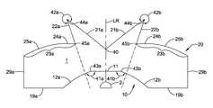
- FIG. 9is a cross-sectional drawing of the lens of FIG. 5 , with element numbers denoting the pertinent corners and zones of the incident and exiting surfaces.
- FIG. 10shows a rotationally symmetric version of the lens of FIG. 5 , according to embodiments described herein.
- FIGS. 11-13show various rotationally asymmetric versions of the lens of FIG. 5 , according to embodiments described herein.
- Embodiments described hereinshow a novel retrofit-style lamp suitable for use in storage units such as refrigeration cases.
- the retrofit-style lampincorporates its own lens instead of relying on a lens attached to the fixture in which the lamp is placed.
- the lensis a one-dimensional linear batwing lens, which produces a batwing type of beam pattern by beam shaping light from a plurality of light sources, which may include LED-based light sources.
- the lensis extruded and is able to be used with any number of light sources.
- the lampalso includes a housing to which the light sources and the lens are attached, with endcaps including electrical pin connectors affixed to each end of the housing.
- the endcapsthrough the electrical pin connectors, allow the light sources to receive power and produce light, which the incorporated one-dimensional linear batwing lens spreads in a substantially uniform pattern through the storage unit.
- the endcapsallow the lamp to be placed in any type of fixture that accepts fluorescent lamp tubes.
- the retrofit-style lampmay also be modified by removing the endcaps and adding covers with appropriate electrical connectors so as to be used as a fixture, directly attached to a storage unit in replacement of a conventional fluorescent lamp fixture.
- FIG. 1shows a retrofit-style lamp 100 (including and corresponding to a cross-sectional view 200 in FIG. 2 and a profile sectional view 300 in FIG. 3 ) including a plurality of light sources 102 , a one-dimensional linear batwing lens 104 , a housing 106 , a pair of endcaps 108 and 110 , and a pair of electrical connectors 112 and 114 .
- the one-dimensional linear batwing lens 104is incorporated into the retrofit-style lamp 100 , such that the fixture (not shown) into which the retrofit-style lamp 100 is placed does not need to have an optic or optics (i.e., lens/lenses) of its own.
- the retrofit-style lamp 100is suitable for placement in any type of fixture, such as but not limited to a conventional fluorescent tube lamp fixture (not shown).
- the one-dimensional linear batwing lens 104is coupled to the housing 106 , as seen most easily in FIG. 2 , to form an outer body of the retrofit-style lamp 100 .
- the one-dimensional linear batwing lens 104may be coupled to the housing 106 in any known way.
- the one-dimensional linear batwing lens 104 and the housing 106are each shaped so as to form as interlocking connection. An example of such an interlocking connection is shown in FIG.
- the one-dimensional linear batwing lens 104 and the housing 106each include a tab 220 N attached to a post 222 N , such that the tabs 220 3 and 220 4 on the one-dimensional linear batwing lens 104 may be slid into the two cavities created by the tabs 220 1 and 220 2 and the posts 222 1 and 222 2 of the housing 106 , keeping the one-dimensional linear batwing lens 104 and the housing 106 connected.
- the tabs 220 N and the posts 222 Nare created from the same material as the housing 106 and/or the one-dimensional linear batwing lens 104 and are a solid part of the housing 106 and/or the one-dimensional linear batwing lens 104 , such that the tabs 220 N and the posts 222 N are created when the housing 106 and/or the one-dimensional linear batwing lens 104 is created (i.e., shaped).
- the tabs 220 N and the posts 222 Nare separate from the housing 106 and/or the one-dimensional linear batwing lens 104 and must be connected or otherwise attached thereto (e.g., by use of an epoxy or other adhesive material, or through use of a mechanical connection).
- the posts 222 Nare a solid part of the housing 106 and/or the one-dimensional linear batwing lens 104 , as described above, and the tabs 220 N are separate and must be connected or otherwise attached to the corresponding posts 222 N (e.g., by use of an epoxy or other adhesive material, or through use of a mechanical connection).
- connection of the housing 106 and the one-dimensional linear batwing lens 104is outside of the active optical field of the one-dimensional linear batwing lens 104 , so that the housing 106 retains and supports the one-dimensional linear batwing lens 104 without disturbing the beam pattern created by the beam shaping of the one-dimensional linear batwing lens 104 , acting on light from the plurality of light sources 102 .
- the housing 106may be made of any material that serves a thermal management function. Thus, in some embodiments, the housing 106 serves as a heat sink for any heat created by the retrofit-style lamp 100 and/or any of its components, such as heat created by, for example, the plurality of light sources 102 ).
- the housing 106is also extrudable (i.e., may be formed having a desired cross-section by being forced through a die).
- the housing 106is made of aluminum.
- the housing 106may be made of, for example but not limited to, sheet metal, a plastic material, and the like.
- the housing 106may be of any shape that allows the retrofit-style lamp 100 to fit into a lighting fixture.
- the housing 106must be able to be connected to the one-dimensional linear batwing lens 104 , using, for example, any of the connection mechanisms described above.
- the housing 106has a low profile, which allows the retrofit-style lamp 100 to be placed into, for example, conventional fluorescent tube fixtures.
- upper walls 240 of the housing 106(seen most easily in FIG. 2 ) provide a precise mechanical cutoff at edges 242 of the housing 106 to eliminate reverse glare from the plurality of light sources 102 .
- the pair of electrical connectors 112 and 114are located, respectively, on either end of the retrofit-style lamp 100 .
- the first of the pair of electrical connectors 112is attached to a first end 182 of the housing 106
- the second of the pair of electrical connectors 114is attached to a second end 184 of the retrofit-style lamp 100 .
- the pair of electrical connectors 112 and 114may be any known type of electrical connector, such as but not limited to a pair of two-pin connector as is typically used on conventional fluorescent lamp tubes.
- the pair of electrical connectors 112 and 114provide the retrofit-style lamp 100 with power received from the fixture (not shown) into which the retrofit-style lamp 100 is placed.
- the power received by the pair of electrical connectors 112 and 114is sent to the plurality of light sources 102 through any power-conducting material, such as but not limited to wire, or pin connectors located on a printed circuit board (PCB) that includes any number of the plurality of light sources 102 .
- the pair of electrical connectors 112 and 114are connected to the joined one-dimensional linear batwing lens 104 and housing 106 (which may be considered to be a lens-housing combination). In some embodiments, the pair of electrical connectors 112 and 114 are directly connected to the lens-housing combination. Alternatively, as is shown in FIG.
- the pair of endcaps 108 and 110is interposed between the lens-housing combination and the pair of electrical connectors 112 and 114 . That is, either of the pair of endcaps 108 and 110 is connectable between one of the pair of electrical connectors 112 and 114 , and the lens-housing combination.
- a first of the pair of endcaps 108is connected between the first of the pair of electrical connectors 112 and the interconnected one-dimensional linear batwing lens 104 and the housing 106
- the second of the pair of endcaps 110is connected between the second of the pair of electrical connectors 114 and the interconnected one-dimensional linear batwing lens 104 and the housing 106 .
- any electrical connection between either or both of the pair of electrical connectors 112 and 114 and the plurality of light sources 102must be maintained (i.e., not interrupted, severed, or otherwise blocked by) the pair of endcaps 108 and 110 .
- the pair of endcaps 108 and 110with the exception of an electrical connection to the pair of electrical connectors 112 and 114 , seal off the interior of the interconnected one-dimensional linear batwing lens 104 and the housing 106 (i.e., the lens-housing combination).
- the pair of endcaps 108 and 110may be made of any material that is able to withstand any heat generated by the retrofit-style lamp 100 without becoming deformed, and without either of the pair of endcaps 108 and 110 becoming disengaged or otherwise disconnected from the other components of the retrofit-style lamp 100 .
- an endcap and an electrical connectormay be a single component, while alternatively, in other embodiments, an endcap and an electrical connector may be discrete components that must be connected in some manner.
- Both the pair of endcaps 108 and 110 and the pair of electrical connectors 112 and 114may be joined to other components of the retrofit-style lamp 100 using any available connection mechanisms and/or materials (for example, but not limited to, mechanical connections, adhesive-based connections, combinations thereof, and so on).
- one or both of the pair of endcaps 108 and 110may be shaped or otherwise formed so that, when the retrofit-style lamp 100 is placed into a fixture, proper engagement of the retrofit-style lamp 100 with the fixture results in the endcap/endcaps “locking” the retrofit-style lamp 100 into place, or otherwise indicating that the retrofit-style lamp 100 has been properly installed into the fixture. In some embodiments, this functionality is found on one or both of the pair of electrical connectors 112 and 114 .
- the “locking” and/or indicator functionality described aboveis found in one or both of the endcap-electrical connector combinations.
- the plurality of light sources 102is arranged within a space 150 defined in part by the housing 106 .
- the space 150may also be defined in part by the one-dimensional linear batwing lens 104 , as well as, or alternatively by, the connection mechanism between the housing 106 and the one-dimensional linear batwing lens 104 .
- the plurality of light sources 102may be any type of light source capable of producing light that may be beam shaped by the one-dimensional linear batwing lens 104 .
- the plurality of light sources 102are a plurality of light-emitting diode(LED)-based light sources, such as but not limited to a plurality of light-emitting diodes (LEDs), a plurality of organic light-emitting diodes (OLEDs), combinations thereof, and the like.
- the retrofit-style lamp 100uses Golden Dragon® LEDs made by OSRAM Opto Semiconductors of Regensburg, Germany, and Sunnyvale, Calif., USA. A single LED 102 1 is shown in FIG. 2 .
- the plurality of LED-based light sourcesmay be arranged, as is well-known in the art, on one or more printed circuit boards (PCBs) that extend from one part of the retrofit-style lamp 100 to another. Where two or more PCBs are used in the retrofit-style lamp 100 , the PCBs are electrically connected to each other to allow all of the LED-based light sources on all the PCBs to be powered from the same source (e.g., the fixture into which the retrofit-style lamp 100 is attached). Any PCBs used are sized to fit within the retrofit-style lamp 100 , which in some embodiments is approximately 1.5 inches wide at its widest point.
- the one-dimensional linear batwing lens 104beam shapes light emitted by at least two light sources of the plurality of light sources.
- the dispersion of light created (i.e., beam shaped) by the one-dimensional linear batwing lens 104is a batwing dispersion, regardless of the number of the light sources, or type of light sources, used.
- any number of light sources, including any number of LEDswith the one-dimensional linear batwing lens 104 ; for example, see FIG. 3 .
- the one-dimensional linear batwing lens 104therefore may be said to be scalable, such that no change is required to the lens to produce a batwing dispersion even if the number of light sources used in the retrofit-style lamp 100 changes.
- FIG. 2which is a cross-section of the retrofit-style lamp 100 shown in FIG. 1
- FIG. 3which is a profile view of a section of the retrofit-style lamp 100 shown in FIG. 1
- the plurality of light sources 102are located in a region 202 beneath a central portion 204 of the one-dimensional linear batwing lens 104 .
- the distance between the top of a light source 102 1e.g., a single LED or a chip of LEDs located in the region 202 , measured from the center 206 of the light source 102 1 , and the bottom edge of the one-dimensional linear batwing lens 104 (i.e., the part of the one-dimensional linear batwing lens 104 that is facing towards the plurality of light sources), measured from the center 208 of a bottom edge 290 of the one-dimensional linear batwing lens 104 , is 3.2 millimeters.
- a light source 102 1e.g., a single LED or a chip of LEDs
- the term retrofit-style lampis one where a conventional light source in an existing fixture is replaced by an LED-based light source and appropriate changes may be further required to at least one of the ballast and/or the power supply of the existing fixture, so as to allow the fixture to properly power and operate the LEDs.
- a retrofit-style lampreplaces the conventional light source, and in some embodiments, may require the existing ballast and/or power supply of the existing fixture to also be replaced.
- a retrofit lampwould replace the conventional light source in an existing fixture with an LED-based light source, but would not require any changes to the already-existing ballast and/or power supply of the conventional fixture.
- a one-dimensional linear batwing lenssuch as the one-dimensional linear batwing lens 104 shown in FIGS. 1-3 , will now be described in more detail.
- a one-dimensional linear batwing lensis a batwing style lens that is extended in one dimension in a linear direction so as to be used with more than a single light source and to produce, through beam shaping, a substantially batwing and/or batwing-type distribution from how many ever light sources are used.
- the distribution produced by a one-dimensional linear batwing lensis a substantially batwing distribution that is substantially uniform within a defined space, such as but not limited to the interior of a refrigeration case (not accounting for the reflective and/or blocking effects of anything contained within the defined space).
- the substantial uniformity of the distributionis such that the light, as beam shaped by the one-dimensional linear batwing lens, fills up a defined space.
- the one-dimensional linear batwing lens 104is extrudable, which results in less expensive tooling costs when the lens is formed.
- the one-dimensional linear batwing lens 104may be made of, for example but not limited to, any transparent polymer that is extrudable, may be connected to a housing without affecting the batwing dispersion of light produced, and is resistant to the heat produced by the plurality of light sources.
- the one-dimensional linear batwing lens 104is made from an acrylic, a polycarbonate (i.e., plastic), or glass, or some combination thereof.
- the extrudable one-dimensional linear batwing lens 104is co-extrudable, that is, one portion of the lens is made from a first material and the other portion of the lens is made from a second material.
- the one-dimensional linear batwing lens 104may be made of both an acrylic and a polycarbonate.
- the co-extrudable one-dimensional linear batwing lensmay be comprised of a first portion and a second portion. The first portion is comprised of a first material and the second portion is comprised of a second material.
- the one-dimensional linear batwing lens 104may be divided into two portions by a straight plane that intersects (i.e., crosses) the entirety of the one-dimensional linear batwing lens 104 in any direction.
- the one-dimensional linear batwing lens 104may, alternatively, be divided into two portions by a curved surface that intersects (i.e., crosses) the entirety of the one-dimensional linear batwing lens 104 in any direction.
- the division of the one-dimensional linear batwing lens 104may be into equal portions (e.g., two halves, each of the same size) or into two unequal portions.
- the one-dimensional linear batwing lens 104may be formed of more than two materials, and thus may be divided into more than two portions, where each portion is made of a different material. Further, in some embodiments, the one-dimensional linear batwing lens 104 may be made of two materials, but may include more than two portions.
- the one-dimensional linear batwing lens 104 in such embodimentsmay be divided by a plurality of intersecting planes, where each plane crosses two distinct outer boundaries of the one-dimensional linear batwing lens 104 .
- any type of dividing shapemay be used. For example, if looking at the cross-section shown in FIG. 2 , there may be a first plane (not shown) that intersects the one-dimensional linear batwing lens 104 in a vertical direction (i.e., from top to bottom, or vice versa), and there may be a second plane that intersects the one-dimensional linear batwing lens 104 in a horizontal direction (i.e., from left to right, or vice versa).
- each portionmay be made from a different material, or one portion may be made of a first material and the remaining portions from a second material, or two portions may be made of a first material and the remaining portions from a second material, and so on.
- the one-dimensional linear batwing lens 104may be made of a material (e.g., acrylic), but may still be divided into portions (two or more). In such embodiments, each portion of the one-dimensional linear batwing lens 104 will be made of the material, but a first portion may include a first filter, a second portion may include a second filter, and so on. As described above with regards to how different materials may be used for the one-dimensional linear batwing lens 104 , similarly, different filters may be applied to different portions of the one-dimensional linear batwing lens 104 in any combination.
- a filtermay include, but is not limited to, different colors, different textures, different diffusion levels, and so on.
- the one-dimensional linear batwing lens 104may be divided into different portions, for example, into two different portions by a horizontal plane that divides the one-dimensional linear batwing lens 104 into an upper portion 170 and a lower portion 172 (shown in FIG. 2 ), where the upper portion 170 is located farther from the plurality of light sources 102 than the lower portion 172 .
- the upper portion 170may then be divided into a first non-planar section and a second non-planar section, for example by a vertical plane that bisects the upper portion 170 (not shown).
- the one-dimensional linear batwing lens 104may be said to be bi-modal.
- the upper portion 170as shown in FIG.
- the dip 174may be characterized by an angle.
- the angle of the dip 174may be between 0° and 180° not inclusive of the end points.
- the first non-planar section and the second non-planar sectionmay be similarly shaped, as is shown in FIG. 2 .
- the first non-planar section and the second non-planar sectionare of different shapes (not shown).
- the first non-planar sectionmay have a top surface that is shaped like a parabola
- the second non-planar sectionmay have a top surface that is shaped like a half-circle, so long as the shape produces the desired batwing-like dispersion.
- the upper portion 170may, at its outermost edge, have any shape that produces the desired batwing-like dispersion.
- the lower portion 172may similarly be of any non-linear shape that results in two cylindrical arcs that are not tangent at the joint (i.e., not a continuous cylindrical arc).
- the outermost edge of the lower portion 172(i.e., the edge closest to the plurality of light sources 102 ) may thus be of any non-linear shape, as long as it corresponds to the shapes of the upper portion 170 of the lens, because the upper portion 170 and the lower portion 172 work together to produce the desired batwing dispersion.
- changing the shape of the one-dimensional linear batwing lens 104may result in changes to the width and/or the thickness of the one-dimensional linear batwing lens 104 .
- the one-dimensional linear batwing lens 104measures 1.386 inches at its widest point (i.e., in a horizontal direction), and measures 0.536 inches at its tallest point (i.e., in a vertical direction), 0 . 358 inches without including the height of the post 222 3 or 222 4 .
- the radius of curvature at the dip 174is R.047, while the radius of curvature at a first curved edge 280 and a second curved edge 282 of the upper portion 170 is R.656, as well as the radius of curvature at a side edge 284 .
- the same radii of curvatureare found on both sides of the upper portion 170 .
- the space between the upper portion 170 at the dip 174 and the center 208 of the bottom edge 290 of the one-dimensional linear batwing lens 104is 0.100 inches.
- the radius of curvature of the bottom edge 290 on either side of the center 208is R.698.
- the one dimensional linear batwing lens 104includes posts 222 to connect to the housing 106
- the distance between a side edge 292 of the post 222 3 and a side edge 294 of the post 222 4is 1.310 inches plus or minus 0.020 inches.
- the retrofit-style lamp 100may include only a single endcap and a single electrical connector at one end, with the other end including only a closure that seals off the interior of the retrofit-style lamp 100 .
- a number of lens-housing combinations, each including a distinct plurality of light sources and a distinct one-dimensional linear batwing lensmay be placed side-by-side, or otherwise combined together, and then joined to the same endcap/pair of endcaps, and/or the same electrical connector/pair of electrical connectors, to form a retrofit-style lamp.
- the retrofit-style lampmay have a generally linear shape, as the retrofit-style lamp 100 shown in FIG.
- the retrofit-style lampmay have a non-linear shape (for example, but not limited to, an “X” shape, a “+” shape, an “*” shape, a “” shape, and so on).
- each distinct arm/leg/side of the shapeincludes at least one one-dimensional linear batwing lens, such that if the arm/leg/side were separated from the rest and provided power, a batwing dispersion would be produced by at least two source of light associated with the lens.
- the pair of electrical connectors 112 and 114 and the endcaps 108 and 110may be removed from the retrofit-style lamp 100 to create a fixture 400 , a portion of which is shown in FIG. 4 .
- the fixture 400thus includes a plurality of light sources 402 (only one of which is shown in FIG. 4 ), a one-dimensional linear batwing lens 404 , a housing 406 , and a power supply (not shown).
- the power supplyis connectable to the housing 406 , and provides power to the fixture 400 , and more specifically, to the plurality of light sources 402 .
- the plurality of light sources 402is located in a region defined, at least in part, by the housing 406 , and the plurality of light sources 402 receive power from the power supply.
- the one-dimensional linear batwing lens 404is coupled to the housing 406 , and beam shapes light emitted by at least two light sources of the plurality of light sources 402 .
- the plurality of light sources 402 , the one-dimensional linear batwing lens 404 , and the housing 406each share the same properties and/or configurations (and/or potential properties and/or configurations) as those of the corresponding components (i.e., the plurality of light sources 102 , the one-dimensional linear batwing lens 104 , and the housing 106 ) for the retrofit-style lamp 100 shown in FIG.
- the one-dimensional linear batwing lens 404 of the fixture 400provides a substantially uniform distribution of light within a space defined in part by an enclosed storage structure (not shown), such as but not limited to a refrigeration case, by beam shaping light emitted by the plurality of light sources 402 .
- an enclosed storage structuresuch as but not limited to a refrigeration case
- beam shaping light emitted by the plurality of light sources 402emitted by the plurality of light sources 402 .
- the fixture 400is fitted with housing closures (not shown in FIG. 4 ) that seal the interior of the fixture 400 .
- housing closuresallow for power to be provided from the power supply to the plurality of light sources 402 located in the interior of the fixture 400 , for example through the use of one or more wires, or any other suitable electrical transmitters.
- FIGS. 5-9It is instructive to provide a specific, non-limiting example of a one-dimensional linear batwing lens, and to provide explanations of the functions of the various features on the example lens.
- the example lens, shown in FIGS. 5-9is assumed to be generally one-dimensional, meaning that the focusing or redirection effects of the lens are in the plane of the page and that there are no focusing or redirection effects out of the plane of the page, and is assumed to be left-right symmetrical.
- FIGS. 10-13Following the symmetrical one-dimensional example of FIGS. 5-9 , rotationally symmetric and asymmetric examples are shown in FIGS. 10-13 .
- Embodiments of the example one-dimension linear batwing lens shown in FIGS. 5-9may be used within the fixture 400 and/or the retrofit-style lamp 100 without limitation.
- the lens fixturemay be mounted along an edge of the cooler and may provide illumination for contents on the shelves in the interior of the cooler.
- the lens in this non-limiting example described with regards to FIGS. 5-9is in the shape of a “generalized cylinder”, meaning that a normal cross-section of the lens has the same size and shape for all longitudinal locations along the lens.
- the term “generalized cylinder”is different from the common usage of “cylinder”, which commonly refers to objects or surfaces having a circular cross-section.
- FIG. 5is a planar cross-section of an exemplary lens 1 , taken so that the plane of the page is perpendicular to the line of light sources 2 , and the line of light sources 2 extends directly out of and into the page.
- the light sources 2themselves may be solid state light sources, such as but not limited to light emitting diodes (LEDs), some or all of which may be encapsulated inside generally hemispherical caps so that each LED is at or near the center of a respective hemisphere.
- each capmay have more than one LED at or near its center.
- the capmay be absent.
- the incident face 10has a central portion 11 that straddles the left-right symmetry plane LR of the lens.
- the central portion 11is essentially planar and essentially perpendicular to the left-right symmetry plane LR, to within typical manufacturing and alignment tolerances.
- the central portion 11may be convex or concave, typically being perpendicular to the left-right symmetry plane LR at the left-right symmetry plane LR.
- a pair of concave peripheral portions 12 a, 12 bextends from opposite sides of the central portion 11 .
- the peripheral portions 12 a, 12 bare truly cylindrical, meaning that their cross-sections are circular in shape.
- the peripheral portions 12 a, 12 bmay have cross-sections that are concave but deviate from true circularity.
- the incident face 10may not have a smoothly-changing surface slope, but instead may have a surface slope discontinuity, or, in other words, a corner 41 a, 41 b. Such a corner may be useful for directing particular light rays to particular regions on the exiting face (shown in FIGS. 6-8 ).
- the corner 41 a, 41 b at the interfaces between the central portion 11 and the respective peripheral portions 12 a, 12 bforms an obtuse angle 43 a, 43 b in air, i.e., an angle between 90 degrees and 180 degrees.
- a pair of generally flat planar portions 19 a, 19 bconnects to the outermost edges of the peripheral portions 12 a, 12 b.
- the only light that strikes these planar portions 19 a, 19 bis reflected from the exiting face 20 of the lens. That is, typically, no light emitted from the source 2 directly strikes the planar portions 19 a, 19 b without first being redirected from some other part of the lens 1 .
- the flat planar portions 19 a, 19 bmay be used for mechanical purposes, such as but not limited to bonding to a supporting structure (not shown in FIG. 5 ).
- the flat planar portions 19 a, 19 bextend to the outermost lateral periphery of the incident face 11 .
- the lens 1may have lateral edges 29 a, 29 b, extending between the incident face 10 and the exiting face 20 along a plane essentially parallel to the left-right symmetry plane LR. As with the planar portions 19 a, 19 b of the incident face 10 , the lateral edges 29 a, 29 b typically do not receive any light directly from the light source 2 without the light first being redirected from another element on the lens 1 . In some embodiments, the lateral edges 29 a, 29 b may be used for mechanical support of the lens 1 .
- an opaque light bafflemay extend around the lateral edges 29 a, 29 b of the lens 1 and across the entire incident face of the lens, where the source 2 is also disposed inside the baffle. Such a baffle may block stray rays from exiting the light fixture in extraneous directions, away from the desired target for the light.
- the exiting face 20 of the lens 1is opposite the incident face 10 , and thus faces away from the light source 2 .
- the exiting face 20includes various structures or elements, with each element performing a different optical task. The elements are first described below with respect to their physical characteristics; their optical functions with respect to traced rays are shown in FIGS. 6-8 .
- central surfaces 21 a, 21 bthat intersect at a concave corner 40 along the left-right symmetry plane LR and typically form an obtuse angle (i.e., between 90 degrees and 180 degrees) in air at their intersection.
- the central surfaces 21 a, 21 bmay form a right angle or an acute angle (i.e., less than 90 degrees) at their intersection, or an angle of 180 degrees or more.
- the central surfaces 21 a, 21 bare typically slightly convex, although they may alternatively be planar or slightly concave.
- a pair of high-incident-angle surfaces 22 a, 22 bextend generally back toward the light source 2 .
- the central surfaces 21 a, 21 b and respective high-incident-angle surfaces 22 a, 22 bform an angle 42 a, 42 b in air greater than 270 degrees at their intersection, and form convex wedges at respective corners 44 a, 44 b.
- the high-incident-angle surfaces 22 ado not point directly at the light source, but point generally toward them, so that if one were to extend the high-incident-angle surfaces 22 a, 22 b toward the incident face 10 of the lens and beyond, they would intersect each other outside the lens 1 , beyond the incident face 10 of the lens 1 and beyond the light source 2 .
- the high-incident-angle surfaces 22 a, 22 bare typically planar, although they may alternatively be slightly convex or slightly concave.
- each partially curved surface 23 a, 23 bhas a generally flat portion 24 a, 24 b directly adjacent to the respective high-incident-angle surface 22 a, 22 b, and has a convex portion 25 a, 25 b extending from the respective generally flat portion 24 a, 24 b.
- the generally flat portions 24 a, 24 bextend perpendicular to the left-right symmetry plane LR.
- the generally flat portions 24 a, 24 bmay be inclined in either direction away from perpendicular to the left-right symmetry plane LR.
- Each partially curved surface 23 a, 23 bmay have a smoothly-changing surface slope at the interface between the generally flat portion 24 a, 24 b and the respective convex portion 25 a, 25 b.
- each partially curved surface 23 a, 23 bmay have a discontinuity in surface slope, or, in other words, a corner, between the generally flat portion 24 a, 24 b and the respective convex portion 25 a, 25 b.
- the generally flat portions 24 a, 24 bare typically essentially planar, they may alternatively be slightly convex or slightly concave.
- the convex portions 25 a, 25 bextend out to the lateral edges 29 a, 29 b of the lens 1 .
- the flat portions 24 a, 24 bdo not serve an optical purpose, but instead simplify the manufacturing process for the lens 1 .
- the lens 1may be molded, where it may be desirable to have partially curved surfaces 23 a, 23 b that increase monotonically in height (or at least do not decrease in height at any point) from the outside edges 29 a, 29 b to the corners 45 a, 45 b.
- the point on the respective partially curved surface 23 a, 23 b that is longitudinally the farthest away from the light source 2is at the respective corner 45 a, 45 b.
- a cone of raysexits the source, typically from the center of the hemispherical cap of the source 2 .
- more lightis emitted “on-axis” (i.e., parallel to the left-right symmetry plane LR) than “off-axis” (i.e., at an angle with respect to the left-right symmetry plane LR).
- the ray paths through the lensare shown in FIGS. 6-8 for three groups of light rays, each group representing a different portion of the cone of light rays that exit the source 2 .
- FIG. 6is a cross-sectional drawing of the lens 1 of FIG. 5 , superimposed with traced rays from the central portion 60 of the emergent cone from the source 2 .
- For the particular central bundle of rays 60light emerges from the source 2 , strikes and refracts through the central portion 11 of the incidence face 10 , transmits through the lens 1 to the central surfaces 21 a, 21 b on the exiting face, and totally internally reflects from the central surfaces 21 a, 21 b. The outermost portion of the particular central bundle then strikes and refracts through the high-incident-angle surfaces 22 a, 22 b, and exit the lens.
- the innermost portion of the particular central bundlestrikes the convex portions 25 a, 25 b of the partially curved surfaces 23 a, 23 b on the exiting face 20 of the lens 1 , where they are totally internally reflected.
- the internally reflected raysare directed toward the incident face 20 or the lateral edges 29 a, 29 b of the lens 1 , where they may exit the lens 1 and may be blocked by an optional light baffle (not shown).
- the central bundle of raysmay follow the paths shown in FIG. 6 .
- the condition for total internal reflectiondictates that the incident angle, formed with respect to a local surface normal, exceeds the critical angle.
- the critical angle for the lensis sin ⁇ 1 (1/n), where n is the refractive index of the lens.
- nis the refractive index of the lens.
- the corresponding critical anglesare in the range of about 36 degrees to about 45 degrees.
- the critical angledetermines the maximum angle at the corner between the central surfaces 21 a and 21 b.
- the maximum corner angle that can still ensure total reflection on either side of the left-right symmetry plane LRis (180 degrees ⁇ 2 ⁇ the critical angle); for refractive indices of 1.4 to 1.7, and corresponding critical angles of 36 degrees to 45 degrees, the maximum corner angle is 102 degrees to 90 degrees.
- the generally flat portions 24 a, 24 bbe roughly parallel to the adjacent rays reflected from the central surfaces 21 a, 21 b, so that no rays from the central bundle of FIG. 6 strike the generally flat portions 24 a, 24 b.
- the generally flat portions 24 a, 24 bmay be beneficial in that they can simplify the molding process for the lens 1 .
- FIG. 7is a cross-sectional drawing of the lens 1 of FIG. 5 , superimposed with traced rays from an intermediate portion 70 (also referred to herein as a particular intermediate bundle of rays 70 ) of the emergent cone of light from the source 2 .
- an intermediate portion 70also referred to herein as a particular intermediate bundle of rays 70
- light emerges from the source 2strikes the high-incident-angle surfaces 22 a, 22 b at a high angle of incidence (hence the name for said surfaces), totally internally reflects off the high-incident-angle surfaces 22 a, 22 b, totally reflects off the central surfaces 21 , 21 b, refracts through the high-incident-angle surfaces 22 a, 22 b, and exits the lens 1 .
- angles of the central surfaces 21 , 21 b and the high-incident-angle surfaces 22 a, 22 bshould be chosen to ensure that the incident angle, with respect to a local surface normal, exceeds the critical angle for each desired total internal reflection.
- the lens embodiments shown in FIGS. 5-8relatively few rays emergent from the source 2 directly strike the high-incident-angle surfaces 22 a, 22 b.
- the high-incident-angle surfaces 22 a, 22 bmay be completely obscured with respect to the source 2 , so that no rays emergent from the source 2 directly strike the high-incident-angle surfaces 22 a, 22 b.
- FIG. 8is a cross-sectional drawing of the lens 1 of FIG. 5 , superimposed with traced rays from an outer portion 80 (also referred to herein as a particular outer bundle of rays 80 ) of the emergent cone from the source 2 .
- an outer portion 80also referred to herein as a particular outer bundle of rays 80
- For the particular outer bundle of rays 80light emerges from the source 2 , strikes and refracts through the concave peripheral portions 12 a, 12 b of the incident face, transmits through the lens 1 to the convex portions 25 a, 25 b of the exiting face 20 , refracts through the convex portions 25 a, 25 b, and exits the lens 1 .
- FIGS. 7 and 8the relative positions of the corner 43 a, 43 b between the central portion 11 and the peripheral portions 12 a, 12 b, and the corner 45 a, 45 b between the high-incident-angle surfaces 22 a, 22 b and the generally flat portions 24 a, 24 b.
- the positions of these corners 43 a, 43 bare chosen so that a ray leaving the source 2 and striking the central portion 11 is directed to either the central surfaces 21 a, 21 b or the high-incident-angle surfaces 22 a, 22 b, and that a ray leaving the source 2 and striking the concave peripheral portions 12 a, 12 b is directed to the convex portions 25 a, 25 b.
- no raysare directed onto the generally flat portions 24 a, 24 b.
- FIG. 9shows the same lens as FIGS. 5-8 , with element numbers 13 a, 13 b, 26 a, 26 b for the above-referenced corners.
- the incident face 10has at least one corner 13 a, 13 b at which the local surface slope changes abruptly; such a corner 13 a, 13 b on the incident face 10 may be referred to as an “incident corner” 13 a, 13 b.
- Such incident corners 13 a, 13 bmay divide the incident face 10 into an incident inner zone 14 (the central portion 11 ) and an incident outer zone 15 (the concave peripheral portions 12 a, 12 b ).
- the exiting face 20has at least one corner 26 a, 26 b at which the local surface slope changes abruptly; such a corner 26 a, 26 b on the exiting face 20 may be referred to as an “exiting corner” 26 a, 26 b.
- Such exiting corners 26 a, 26 bmay divide the exiting face 20 into an exiting inner zone 27 (the central surfaces 21 a, 21 b, plus the high-incident-angle surfaces 22 a, 22 b, which together form a convex wedge) and an exiting outer zone 28 (the partially curved surfaces 23 a 23 b ).
- said raystrikes the exiting inner zone 27 .
- the lensis one-dimensional and is symmetric about a left-right symmetry plane LR.
- FIGS. 10-13There are other examples, shown in FIGS. 10-13 , where the lens is rotationally symmetric ( FIG. 10 ) or is asymmetric ( FIGS. 11-13 ).
- FIG. 10is a plan drawing of a lens 1 having the cross-section shown in FIGS. 5-9 , but being rotationally symmetric rather than left-right symmetric.
- a lens 1may be used for an LED or a cluster of LEDs all located in a reasonably small patch, compared with the one-dimensional lenses of FIGS. 5-9 that may be used with an extended line of LEDs or other extended shapes.
- the output from the rotationally symmetric lens 1 of FIG. 10is also generally rotationally symmetric, or at least has the symmetric properties of the LED or other light source.
- FIG. 11is a cross-sectional drawing of an asymmetric lens, with elements ending in “c” being on one side of the left-right symmetry plane LR and element ending in “b” being on the other side of the left-right symmetry plane LR. It is understood that the light emission will appear different for the left and right sides of lens 1 in FIG. 11 .
- the lighthas a “near-field” pattern, in which the rays' location and direction are both important. Rays arrive at the target with a particular angle emergent from the lens. Importantly, rays also arrive from a particular “starting point” somewhere within or on the structure of the lens; the lens itself dictates where the rays to appear to originate from. Farther out from the lens, typically a few inches away from the lens, a “far-field” pattern becomes more predictive of the light distribution. In the far-field, the ray propagation direction becomes more important than the ray's apparent origination location on the lens. Many inches away from the lens, a shift in ray position produces less of an effect than when the target is very close to the lens.
- near-field and far-field patternsOne artifact of the distinction between near-field and far-field patterns is that the desired distribution along a particular target plane or target volume generally requires consideration of the near-field pattern; the ray location should be considered when possible, not just the ray propagation angle. Note that even though two lenses may have similar-looking far-field distributions (output vs. angle), their near-field patterns may differ due to features that shift the rays, such as the wedge-shaped surfaces on the exiting face of the present lens.
- the lensmay help achieve a uniform spatial distribution of light, which is illuminance (in units such as lux or foot-candle), along a particular plane, about three inches from the lens. It will be understood that the present lens may be modified to achieve whatever distribution of light is desired, for the desired area or volume to be illuminated.
- illuminancein units such as lux or foot-candle
- FIG. 12is a cross-sectional drawing of an asymmetric lens, with the “right” side of the lens having the cross-section described above, and the “left” side having a cross-section 30 that lacks the wedge-shaped elements on the exiting face of the lens 1 .
- FIG. 13is a cross-sectional drawing of an asymmetric lens, having no elements on the “left” side of longitudinal axis A.
- the central face along axis Amay be mirrored, or may be proximate a mirror or other light-directing or absorbing element.
- the designations of “a”, “b”, and “c” on the elementsmay be used interchangeably or may be omitted entirely.
- corner 43is analogous in structure and function to corners 43 a and 43 b from the earlier figures.
Landscapes
- Engineering & Computer Science (AREA)
- General Engineering & Computer Science (AREA)
- Physics & Mathematics (AREA)
- Optics & Photonics (AREA)
- General Physics & Mathematics (AREA)
- Microelectronics & Electronic Packaging (AREA)
- Spectroscopy & Molecular Physics (AREA)
- Non-Portable Lighting Devices Or Systems Thereof (AREA)
Abstract
Description
Claims (20)
Priority Applications (5)
| Application Number | Priority Date | Filing Date | Title |
|---|---|---|---|
| US13/023,571US8434914B2 (en) | 2009-12-11 | 2011-02-09 | Lens generating a batwing-shaped beam distribution, and method therefor |
| PCT/US2012/023965WO2012109141A1 (en) | 2011-02-09 | 2012-02-06 | Lens generating a batwing-shaped beam distribution, and method therefor |
| CN201280008156.3ACN103348182B (en) | 2011-02-09 | 2012-02-06 | Lens and method for generating batwing-like beam distribution |
| KR1020137023700AKR101496258B1 (en) | 2011-02-09 | 2012-02-06 | Lens generating a batwing-shaped beam distribution, and method therefor |
| EP12706735.3AEP2673558A1 (en) | 2011-02-09 | 2012-02-06 | Lens generating a batwing-shaped beam distribution, and method therefor |
Applications Claiming Priority (2)
| Application Number | Priority Date | Filing Date | Title |
|---|---|---|---|
| US12/636,524US20110141729A1 (en) | 2009-12-11 | 2009-12-11 | Retrofit-Style Lamp and Fixture, Each Including a One-Dimensional Linear Batwing Lens |
| US13/023,571US8434914B2 (en) | 2009-12-11 | 2011-02-09 | Lens generating a batwing-shaped beam distribution, and method therefor |
Related Parent Applications (1)
| Application Number | Title | Priority Date | Filing Date |
|---|---|---|---|
| US12/636,524Continuation-In-PartUS20110141729A1 (en) | 2009-12-11 | 2009-12-11 | Retrofit-Style Lamp and Fixture, Each Including a One-Dimensional Linear Batwing Lens |
Publications (2)
| Publication Number | Publication Date |
|---|---|
| US20110141734A1 US20110141734A1 (en) | 2011-06-16 |
| US8434914B2true US8434914B2 (en) | 2013-05-07 |
Family
ID=45774322
Family Applications (1)
| Application Number | Title | Priority Date | Filing Date |
|---|---|---|---|
| US13/023,571Active2030-05-14US8434914B2 (en) | 2009-12-11 | 2011-02-09 | Lens generating a batwing-shaped beam distribution, and method therefor |
Country Status (5)
| Country | Link |
|---|---|
| US (1) | US8434914B2 (en) |
| EP (1) | EP2673558A1 (en) |
| KR (1) | KR101496258B1 (en) |
| CN (1) | CN103348182B (en) |
| WO (1) | WO2012109141A1 (en) |
Cited By (51)
| Publication number | Priority date | Publication date | Assignee | Title |
|---|---|---|---|---|
| US20120147476A1 (en)* | 2010-12-10 | 2012-06-14 | Hui-Hsiung Lin | Collimating optical element, collimating optical assembly, collimating optical array and collimating optical module |
| US20120224369A1 (en)* | 2011-03-02 | 2012-09-06 | Beghelli S.P.A. | Lighting fixture with controlled photometric light emission |
| US20130051030A1 (en)* | 2011-08-30 | 2013-02-28 | Chang Mo LEE | Asymmetric type lens and street lamp including the same |
| US20130100679A1 (en)* | 2011-10-25 | 2013-04-25 | Uniled Lighting Taiwan Inc. | Side illumination lens for led |
| US20140092615A1 (en)* | 2012-10-03 | 2014-04-03 | Varroc Lighting Systems S.R.O. | Concentric lighting module with conical mirror |
| USD705975S1 (en) | 2013-08-20 | 2014-05-27 | Delta T Corporation | Lighting fixture |
| USD705976S1 (en) | 2013-08-20 | 2014-05-27 | Delta T Corporation | Lighting fixture |
| USD706480S1 (en) | 2013-08-20 | 2014-06-03 | Delta T Corporation | Lighting fixture |
| US8807785B2 (en) | 2008-05-23 | 2014-08-19 | Ilumisys, Inc. | Electric shock resistant L.E.D. based light |
| US8840282B2 (en) | 2010-03-26 | 2014-09-23 | Ilumisys, Inc. | LED bulb with internal heat dissipating structures |
| US20140293615A1 (en)* | 2011-07-29 | 2014-10-02 | Tsmc Solid State Lighting Ltd. | Wide angle based indoor lighting lamp |
| US8894430B2 (en) | 2010-10-29 | 2014-11-25 | Ilumisys, Inc. | Mechanisms for reducing risk of shock during installation of light tube |
| US20140347885A1 (en)* | 2013-03-15 | 2014-11-27 | Cree, Inc. | Optical Waveguide Bodies and Luminaires Utilizing Same |
| US8901823B2 (en) | 2008-10-24 | 2014-12-02 | Ilumisys, Inc. | Light and light sensor |
| US20140355302A1 (en)* | 2013-03-15 | 2014-12-04 | Cree, Inc. | Outdoor and/or Enclosed Structure LED Luminaire for General Illumination Applications, Such as Parking Lots and Structures |
| US8928025B2 (en) | 2007-12-20 | 2015-01-06 | Ilumisys, Inc. | LED lighting apparatus with swivel connection |
| US8946996B2 (en) | 2008-10-24 | 2015-02-03 | Ilumisys, Inc. | Light and light sensor |
| US9013119B2 (en) | 2010-03-26 | 2015-04-21 | Ilumisys, Inc. | LED light with thermoelectric generator |
| US9101026B2 (en) | 2008-10-24 | 2015-08-04 | Ilumisys, Inc. | Integration of LED lighting with building controls |
| US9163794B2 (en) | 2012-07-06 | 2015-10-20 | Ilumisys, Inc. | Power supply assembly for LED-based light tube |
| US9184518B2 (en) | 2012-03-02 | 2015-11-10 | Ilumisys, Inc. | Electrical connector header for an LED-based light |
| US9267650B2 (en) | 2013-10-09 | 2016-02-23 | Ilumisys, Inc. | Lens for an LED-based light |
| US9271367B2 (en) | 2012-07-09 | 2016-02-23 | Ilumisys, Inc. | System and method for controlling operation of an LED-based light |
| US9285084B2 (en) | 2013-03-14 | 2016-03-15 | Ilumisys, Inc. | Diffusers for LED-based lights |
| US9291320B2 (en) | 2013-01-30 | 2016-03-22 | Cree, Inc. | Consolidated troffer |
| US9353939B2 (en) | 2008-10-24 | 2016-05-31 | iLumisys, Inc | Lighting including integral communication apparatus |
| US9366396B2 (en) | 2013-01-30 | 2016-06-14 | Cree, Inc. | Optical waveguide and lamp including same |
| US9389367B2 (en) | 2013-01-30 | 2016-07-12 | Cree, Inc. | Optical waveguide and luminaire incorporating same |
| US9411086B2 (en) | 2013-01-30 | 2016-08-09 | Cree, Inc. | Optical waveguide assembly and light engine including same |
| US9442243B2 (en) | 2013-01-30 | 2016-09-13 | Cree, Inc. | Waveguide bodies including redirection features and methods of producing same |
| US9510400B2 (en) | 2014-05-13 | 2016-11-29 | Ilumisys, Inc. | User input systems for an LED-based light |
| US9574717B2 (en) | 2014-01-22 | 2017-02-21 | Ilumisys, Inc. | LED-based light with addressed LEDs |
| US9625638B2 (en) | 2013-03-15 | 2017-04-18 | Cree, Inc. | Optical waveguide body |
| US9645303B2 (en) | 2013-03-15 | 2017-05-09 | Cree, Inc. | Luminaires utilizing edge coupling |
| US9690029B2 (en) | 2013-01-30 | 2017-06-27 | Cree, Inc. | Optical waveguides and luminaires incorporating same |
| USD800367S1 (en) | 2015-09-18 | 2017-10-17 | Delta Corporation | Lighting fixture |
| US9798072B2 (en) | 2013-03-15 | 2017-10-24 | Cree, Inc. | Optical element and method of forming an optical element |
| US9869432B2 (en) | 2013-01-30 | 2018-01-16 | Cree, Inc. | Luminaires using waveguide bodies and optical elements |
| USD811627S1 (en) | 2016-06-16 | 2018-02-27 | Curtis Alan Roys | LED lamp |
| US9920901B2 (en) | 2013-03-15 | 2018-03-20 | Cree, Inc. | LED lensing arrangement |
| US10161568B2 (en) | 2015-06-01 | 2018-12-25 | Ilumisys, Inc. | LED-based light with canted outer walls |
| US10176689B2 (en) | 2008-10-24 | 2019-01-08 | Ilumisys, Inc. | Integration of led lighting control with emergency notification systems |
| US10209429B2 (en) | 2013-03-15 | 2019-02-19 | Cree, Inc. | Luminaire with selectable luminous intensity pattern |
| USD851816S1 (en) | 2017-04-14 | 2019-06-18 | Curtis A. Roys | Lamp support |
| US10416377B2 (en) | 2016-05-06 | 2019-09-17 | Cree, Inc. | Luminaire with controllable light emission |
| US10436970B2 (en) | 2013-03-15 | 2019-10-08 | Ideal Industries Lighting Llc | Shaped optical waveguide bodies |
| US10502899B2 (en)* | 2013-03-15 | 2019-12-10 | Ideal Industries Lighting Llc | Outdoor and/or enclosed structure LED luminaire |
| USD901754S1 (en) | 2017-04-14 | 2020-11-10 | RetroLED Components, LLC | Lamp support |
| US11002438B2 (en) | 2019-04-03 | 2021-05-11 | Sidney Howard Norton | Adjustable clip-on base for LED assembly |
| US11112083B2 (en) | 2013-03-15 | 2021-09-07 | Ideal Industries Lighting Llc | Optic member for an LED light fixture |
| US11719882B2 (en) | 2016-05-06 | 2023-08-08 | Ideal Industries Lighting Llc | Waveguide-based light sources with dynamic beam shaping |
Families Citing this family (75)
| Publication number | Priority date | Publication date | Assignee | Title |
|---|---|---|---|---|
| KR101007134B1 (en)* | 2009-06-05 | 2011-01-10 | 엘지이노텍 주식회사 | Lighting device |
| US20110141729A1 (en)* | 2009-12-11 | 2011-06-16 | Osram Sylvania Inc. | Retrofit-Style Lamp and Fixture, Each Including a One-Dimensional Linear Batwing Lens |
| CN102985750B (en)* | 2010-07-08 | 2014-07-02 | 恩普乐股份有限公司 | Luminous flux control member and illumination device |
| KR101756825B1 (en)* | 2010-08-24 | 2017-07-11 | 삼성전자주식회사 | Optical lens, led module and lighting apparatus having the optical lens |
| US10883702B2 (en) | 2010-08-31 | 2021-01-05 | Ideal Industries Lighting Llc | Troffer-style fixture |
| US9822951B2 (en) | 2010-12-06 | 2017-11-21 | Cree, Inc. | LED retrofit lens for fluorescent tube |
| US10309627B2 (en) | 2012-11-08 | 2019-06-04 | Cree, Inc. | Light fixture retrofit kit with integrated light bar |
| US9581312B2 (en)* | 2010-12-06 | 2017-02-28 | Cree, Inc. | LED light fixtures having elongated prismatic lenses |
| US9494293B2 (en)* | 2010-12-06 | 2016-11-15 | Cree, Inc. | Troffer-style optical assembly |
| US8876325B2 (en)* | 2011-07-01 | 2014-11-04 | Cree, Inc. | Reverse total internal reflection features in linear profile for lighting applications |
| US10823347B2 (en) | 2011-07-24 | 2020-11-03 | Ideal Industries Lighting Llc | Modular indirect suspended/ceiling mount fixture |
| CN103090309B (en)* | 2011-10-28 | 2017-09-19 | 欧司朗股份有限公司 | Lens and the asymmetrical beam distribution of illumination device with the lens |
| US9423117B2 (en) | 2011-12-30 | 2016-08-23 | Cree, Inc. | LED fixture with heat pipe |
| US10544925B2 (en) | 2012-01-06 | 2020-01-28 | Ideal Industries Lighting Llc | Mounting system for retrofit light installation into existing light fixtures |
| US9777897B2 (en) | 2012-02-07 | 2017-10-03 | Cree, Inc. | Multiple panel troffer-style fixture |
| US9698322B2 (en)* | 2012-02-07 | 2017-07-04 | Cree, Inc. | Lighting device and method of making lighting device |
| US8905575B2 (en) | 2012-02-09 | 2014-12-09 | Cree, Inc. | Troffer-style lighting fixture with specular reflector |
| DE112013003456T5 (en) | 2012-03-05 | 2015-05-07 | Seoul Semiconductor Co., Ltd. | Illuminating lens for short-distance illumination |
| US9494294B2 (en) | 2012-03-23 | 2016-11-15 | Cree, Inc. | Modular indirect troffer |
| US9310038B2 (en) | 2012-03-23 | 2016-04-12 | Cree, Inc. | LED fixture with integrated driver circuitry |
| US10054274B2 (en) | 2012-03-23 | 2018-08-21 | Cree, Inc. | Direct attach ceiling-mounted solid state downlights |
| DE102012106624A1 (en)* | 2012-04-04 | 2013-10-10 | Siteco Beleuchtungstechnik Gmbh | Lens element, in particular for emergency lighting module |
| US9360185B2 (en) | 2012-04-09 | 2016-06-07 | Cree, Inc. | Variable beam angle directional lighting fixture assembly |
| US9874322B2 (en) | 2012-04-10 | 2018-01-23 | Cree, Inc. | Lensed troffer-style light fixture |
| US9285099B2 (en) | 2012-04-23 | 2016-03-15 | Cree, Inc. | Parabolic troffer-style light fixture |
| CN102818216B (en)* | 2012-06-05 | 2014-08-06 | 佛山市国星光电股份有限公司 | Large-angle lens and large-angle light-emergent LED (Light Emitting Diode) light source module |
| US8931929B2 (en) | 2012-07-09 | 2015-01-13 | Cree, Inc. | Light emitting diode primary optic for beam shaping |
| CN103672728B (en)* | 2012-09-13 | 2017-09-08 | 赛尔富电子有限公司 | Lens, LED modules and the illuminator using the LED modules |
| US20140092596A1 (en)* | 2012-09-28 | 2014-04-03 | Linear Lighting Corp. | Dimmable, high-efficiency led linear lighting system with interchangeable features and methods for producing same |
| CN202947077U (en)* | 2012-10-16 | 2013-05-22 | 欧司朗股份有限公司 | Lens and light-emitting device |
| CN104718410A (en)* | 2012-10-19 | 2015-06-17 | 皇家飞利浦有限公司 | Lighting device for indirect illumination |
| US9494304B2 (en) | 2012-11-08 | 2016-11-15 | Cree, Inc. | Recessed light fixture retrofit kit |
| US8864346B2 (en) | 2012-12-10 | 2014-10-21 | GE Lighting Solutions, LLC | Lens-reflector combination for batwing light distribution |
| US10648643B2 (en) | 2013-03-14 | 2020-05-12 | Ideal Industries Lighting Llc | Door frame troffer |
| US9052075B2 (en) | 2013-03-15 | 2015-06-09 | Cree, Inc. | Standardized troffer fixture |
| US9080746B2 (en) | 2013-03-15 | 2015-07-14 | Abl Ip Holding Llc | LED assembly having a refractor that provides improved light control |
| US20140268812A1 (en)* | 2013-03-15 | 2014-09-18 | Abl Ip Holding Llc | Led Assembly Having a Reflector That Provides Improved Light Control |
| US9518716B1 (en)* | 2013-03-26 | 2016-12-13 | Universal Lighting Technologies, Inc. | Linear wide area lighting system |
| KR102082335B1 (en) | 2013-04-23 | 2020-02-27 | 엘지이노텍 주식회사 | Lighting device |
| US10302275B2 (en) | 2013-06-19 | 2019-05-28 | Bright View Technologies Corporation | Microstructure-based diffusers for creating batwing lighting patterns |
| EP3011372B1 (en) | 2013-06-19 | 2021-12-08 | Bright View Technologies Corporation | Microstructure-based optical diffuser for creating batwing patterns and method for its manufacture |
| TW201500776A (en)* | 2013-06-28 | 2015-01-01 | 鴻海精密工業股份有限公司 | Lens and light source module with the same |
| US9233510B2 (en) | 2013-07-22 | 2016-01-12 | GE Lighting Solutions, LLC | Lenses for cosine cubed, typical batwing, flat batwing distributions |
| CN104197275A (en)* | 2013-07-22 | 2014-12-10 | 欧司朗有限公司 | Lens used for light source |
| EP3014173A4 (en) | 2013-07-26 | 2017-01-11 | Bright View Technologies Corporation | Shaped microstructure-based optical diffusers |
| USD786471S1 (en) | 2013-09-06 | 2017-05-09 | Cree, Inc. | Troffer-style light fixture |
| US9279550B2 (en) | 2013-10-09 | 2016-03-08 | GE Lighting Solutions, LLC | Luminaires having batwing photometric distribution |
| GB2519553A (en)* | 2013-10-24 | 2015-04-29 | Many Wain Entpr Co Ltd | Optical assembly of an alert light |
| USD772465S1 (en) | 2014-02-02 | 2016-11-22 | Cree Hong Kong Limited | Troffer-style fixture |
| USD807556S1 (en) | 2014-02-02 | 2018-01-09 | Cree Hong Kong Limited | Troffer-style fixture |
| US10451253B2 (en) | 2014-02-02 | 2019-10-22 | Ideal Industries Lighting Llc | Troffer-style fixture with LED strips |
| USD749768S1 (en) | 2014-02-06 | 2016-02-16 | Cree, Inc. | Troffer-style light fixture with sensors |
| US10527225B2 (en) | 2014-03-25 | 2020-01-07 | Ideal Industries, Llc | Frame and lens upgrade kits for lighting fixtures |
| US9683717B1 (en)* | 2014-05-12 | 2017-06-20 | Universal Lighting Technologies, Inc. | Asymmetric area lens for low-profile lighting system |
| CN105318274B (en)* | 2014-07-24 | 2020-04-21 | 中强光电股份有限公司 | Lens and backlight module |
| US20160076706A1 (en)* | 2014-09-17 | 2016-03-17 | Ge Lighting Solutions, Llc. | Method and system for led lamp incorporating internal optics for specific light distribution |
| ES2855273T3 (en)* | 2014-10-23 | 2021-09-23 | Oy Mtg Meltron Ltd | Lighting fixture and transmitting element for this fixture |
| JP6507035B2 (en)* | 2015-06-03 | 2019-04-24 | 株式会社エンプラス | Light flux control member, light emitting device and lighting device |
| US10012354B2 (en) | 2015-06-26 | 2018-07-03 | Cree, Inc. | Adjustable retrofit LED troffer |
| US9903561B1 (en) | 2015-11-09 | 2018-02-27 | Abl Ip Holding Llc | Asymmetric vision enhancement optics, luminaires providing asymmetric light distributions and associated methods |
| CN106439730A (en)* | 2016-08-19 | 2017-02-22 | 江苏恒鹏智能电气有限公司 | Strip special-shape lens and LED lamp illuminant component based on strip special-shape lens |
| US10948156B2 (en) | 2016-11-22 | 2021-03-16 | Signify Holding B.V. | Cover for LED luminaires |
| US10337693B1 (en)* | 2017-02-10 | 2019-07-02 | Musco Corporation | Apparatus method, and system for cost-effective lighting system retrofits including LED luminaires |
| US10546985B2 (en)* | 2017-03-28 | 2020-01-28 | Nanosys, Inc. | Method for increasing the light output of microLED devices using quantum dots |
| NL2018788B1 (en)* | 2017-04-26 | 2018-11-05 | De Zeven Son B V | Lighting element as well as lighting provided with the lighting element |
| JP7087438B2 (en)* | 2018-02-22 | 2022-06-21 | 船井電機株式会社 | Lighting device and display device |
| JP6729627B2 (en)* | 2018-04-20 | 2020-07-22 | 日亜化学工業株式会社 | Light source module |
| US12164175B2 (en)* | 2019-02-27 | 2024-12-10 | Kyocera Corporation | Mounting package for an optical element with inclined transmission film and flat mirror |
| IT201900010713A1 (en)* | 2019-07-02 | 2021-01-02 | Itl S R L | Extruded lens for light radiation distribution, lamp, lamp holder assembly and merchandise display |
| CN210860805U (en)* | 2019-12-02 | 2020-06-26 | 苏州欧普照明有限公司 | Lamp fitting |
| US11073653B2 (en) | 2019-12-19 | 2021-07-27 | Lumileds Llc | Edge coupled light collimation for backlight |
| JP7605525B2 (en)* | 2020-08-31 | 2024-12-24 | 華為技術有限公司 | Lens module, camera module, and terminal |
| CN214580892U (en)* | 2020-12-28 | 2021-11-02 | 苏州欧普照明有限公司 | Hyperboloid lens and LED lamps and lanterns |
| CN112728502B (en)* | 2020-12-31 | 2022-12-06 | 美智光电科技股份有限公司 | Lenses and Lamps |
| US12338978B1 (en)* | 2024-04-16 | 2025-06-24 | Illumination Enterprises Inc. | Track lighting system and luminaire with multiple LEDs |
Citations (64)
| Publication number | Priority date | Publication date | Assignee | Title |
|---|---|---|---|---|
| US2215900A (en) | 1939-10-28 | 1940-09-24 | Ralph E Bitner | Catadioptrical lens |
| US2254961A (en) | 1937-08-21 | 1941-09-02 | George M Cressaty | Unitary lens system |
| US2469080A (en) | 1945-05-09 | 1949-05-03 | Cressaty | Unitary lens unit |
| US2515584A (en) | 1948-11-12 | 1950-07-18 | Avco Mfg Corp | Edge illuminated shelf for refrigerator cabinets |
| US4414609A (en) | 1982-10-08 | 1983-11-08 | Sylvan R. Shemitz And Associates, Inc. | Luminaire for a visual display terminal |
| US4667481A (en) | 1984-09-11 | 1987-05-26 | Hitachi Plant Engineering & Construction Co., Ltd. | Method of and apparatus for emitting light in ice |
| US4767172A (en) | 1983-01-28 | 1988-08-30 | Xerox Corporation | Collector for an LED array |
| US4907044A (en) | 1987-10-15 | 1990-03-06 | Siemens Aktiengesellschaft | Optical emission device |
| US5027258A (en) | 1989-06-19 | 1991-06-25 | Inotec Gmbh Gesellschaft Fur Innovative Technik | Display unit |
| US5471372A (en) | 1993-12-06 | 1995-11-28 | Ardco, Inc. | Lighting system for commercial refrigerator doors |
| US5526190A (en) | 1994-09-29 | 1996-06-11 | Xerox Corporation | Optical element and device for providing uniform irradiance of a surface |
| EP0751340A2 (en) | 1995-06-27 | 1997-01-02 | Lumitex, Inc. | Light emitting panel assemblies |
| US5607227A (en) | 1993-08-27 | 1997-03-04 | Sanyo Electric Co., Ltd. | Linear light source |
| DE29717444U1 (en) | 1997-09-30 | 1998-01-08 | Austria Haustechnik Ag, Rottenmann | Infrared-free and ultraviolet-free lighting of goods cooled in a refrigerator |
| WO1998014740A1 (en) | 1996-10-03 | 1998-04-09 | Imperial Chemical Industries Plc | Illumination system |
| DE29814243U1 (en) | 1998-07-08 | 1998-11-05 | Liebherr Hausgeraete | Interior lighting for cooling unit |
| US6179434B1 (en) | 1999-02-03 | 2001-01-30 | Illumitech, Llc. | Modular lighting system for product display unit |
| US6547423B2 (en) | 2000-12-22 | 2003-04-15 | Koninklijke Phillips Electronics N.V. | LED collimation optics with improved performance and reduced size |
| US6578979B2 (en) | 2000-09-26 | 2003-06-17 | Lisa Lux Gmbh | Illumination body for refrigeration devices |
| US6582103B1 (en) | 1996-12-12 | 2003-06-24 | Teledyne Lighting And Display Products, Inc. | Lighting apparatus |
| EP0971186B1 (en) | 1998-07-08 | 2003-08-20 | Liebherr-Hausgeräte Ochsenhausen GmbH | Interior lighting for refrigerator |
| US6632100B1 (en) | 1997-04-23 | 2003-10-14 | Anthony, Inc. | Lighting system method and apparatus socket assembly lamp insulator assembly and components thereof |
| US6638088B1 (en) | 1997-04-23 | 2003-10-28 | Anthony, Inc. | Lighting circuit, lighting system method and apparatus, socket assembly, lamp insulator assembly and components thereof |
| US6724543B1 (en) | 2002-10-23 | 2004-04-20 | Visteon Global Technologies, Inc. | Light collection assembly having mixed conic shapes for use with various light emitting sources |
| US6755556B2 (en) | 2002-02-21 | 2004-06-29 | Valeo Vision | Indicator light comprising an optical piece fulfilling an indicating function autonomously |
| US6762562B2 (en) | 2002-11-19 | 2004-07-13 | Denovo Lighting, Llc | Tubular housing with light emitting diodes |
| US6853151B2 (en) | 2002-11-19 | 2005-02-08 | Denovo Lighting, Llc | LED retrofit lamp |
| US6896381B2 (en) | 2002-10-11 | 2005-05-24 | Light Prescriptions Innovators, Llc | Compact folded-optics illumination lens |
| US6936968B2 (en) | 2001-11-30 | 2005-08-30 | Mule Lighting, Inc. | Retrofit light emitting diode tube |
| US20050201118A1 (en) | 2004-03-12 | 2005-09-15 | Olympus Corporation | Optical element, compound optical element, and illuminating apparatus |
| US6953271B2 (en) | 2002-10-28 | 2005-10-11 | Valeo Vision | Indicator lamp comprising an optical device for recovering and distributing the light flux towards an annular reflector |
| US7021797B2 (en) | 2003-05-13 | 2006-04-04 | Light Prescriptions Innovators, Llc | Optical device for repositioning and redistributing an LED's light |
| US7067992B2 (en) | 2002-11-19 | 2006-06-27 | Denovo Lighting, Llc | Power controls for tube mounted LEDs with ballast |
| US7111964B2 (en) | 2003-03-14 | 2006-09-26 | Toyoda Gosei Co., Ltd. | LED package |
| US7121675B2 (en) | 2002-01-10 | 2006-10-17 | Artak Ter-Hovhannisian | Low temperature LED lighting system |
| US20060232961A1 (en) | 2005-04-15 | 2006-10-19 | David Pfund | Compact task ambient luminaire with twin tube lamp |
| EP1717627A1 (en) | 2005-04-26 | 2006-11-02 | LG Electronics, Inc. | Optical lens, light emitting device package using the optical lens, and backlight unit |
| US7254309B1 (en) | 2006-07-14 | 2007-08-07 | Coretronic Corporation | Side emitting LED and lens |
| US7270454B2 (en) | 2004-01-13 | 2007-09-18 | Koito Manufacturing Co., Ltd. | Vehicular lamp |
| EP1860467A1 (en) | 2006-05-24 | 2007-11-28 | Industrial Technology Research Institute | Lens and light emitting diode using the lens to achieve homogeneous illumination |
| WO2008000020A1 (en) | 2006-06-29 | 2008-01-03 | Fermiscan Australia Pty Limited | Improved process |
| US7329029B2 (en) | 2003-05-13 | 2008-02-12 | Light Prescriptions Innovators, Llc | Optical device for LED-based lamp |
| US20080054281A1 (en) | 2006-08-31 | 2008-03-06 | Nadarajah Narendran | High-efficient light engines using light emitting diodes |
| WO2008090574A1 (en) | 2007-01-26 | 2008-07-31 | Sic Divisione Elettronica S.R.L. | Lens for a light emitting diode and manufacturing method therefor |
| US20080198600A1 (en) | 2006-01-09 | 2008-08-21 | Stylmark, Inc. | Light emitting diode lighting assembly |
| US7465074B2 (en) | 2004-07-20 | 2008-12-16 | Osram Opto Semiconductors Gmbh | Optical element |
| US20090002990A1 (en) | 2007-06-29 | 2009-01-01 | Aaron James Becker | Led lighting assemblies for display cases |
| US7473013B2 (en) | 2003-12-10 | 2009-01-06 | Okaya Electric Industries Co., Ltd. | Indicator lamp having a converging lens |
| US7490957B2 (en) | 2002-11-19 | 2009-02-17 | Denovo Lighting, L.L.C. | Power controls with photosensor for tube mounted LEDs with ballast |
| JP2009043686A (en) | 2007-08-10 | 2009-02-26 | Koha Co Ltd | Lighting device and vending machine equipped with the same |
| US20090059620A1 (en) | 2007-08-28 | 2009-03-05 | Chunghwa Picture Tubes, Ltd. | Back light module |
| US7507001B2 (en) | 2002-11-19 | 2009-03-24 | Denovo Lighting, Llc | Retrofit LED lamp for fluorescent fixtures without ballast |
| WO2009052172A2 (en) | 2007-10-15 | 2009-04-23 | Hussmann Corporation | Led lighting assembly with leds having different viewing angles |
| US20090225543A1 (en) | 2008-03-05 | 2009-09-10 | Cree, Inc. | Optical system for batwing distribution |
| US20090284951A1 (en) | 2006-06-30 | 2009-11-19 | Julius Muschaweck | Optoelectronic component and illumination device |
| US20100027256A1 (en) | 2008-08-04 | 2010-02-04 | Harison Toshiba Lighting Corp. | Optical element for arrayed light source and light emitting device using the same |
| US7731395B2 (en) | 2005-01-26 | 2010-06-08 | Anthony International | Linear lenses for LEDs |
| US20100195335A1 (en) | 2009-02-03 | 2010-08-05 | Osram Sylvania, Inc. | Beam spreading optics for light emitting diodes |
| US7798679B2 (en) | 2007-08-09 | 2010-09-21 | Sharp Kabushiki Kaisha | Light emitting device and lighting device having the same |
| US7847480B2 (en) | 2002-05-17 | 2010-12-07 | Ccs, Inc. | Light emitting diode unit and method for manufacturing light emitting diode unit |
| US7880188B2 (en) | 2005-02-28 | 2011-02-01 | Osram Opto Semiconductors Gmbh | Illumination device |
| US7942558B2 (en) | 2005-09-30 | 2011-05-17 | Zweig Frederic | Optical device for LED light sources |
| WO2012000020A1 (en) | 2010-06-28 | 2012-01-05 | Wood, Stephen Raymond | Temporary fence base |
| WO2012072387A1 (en) | 2010-11-29 | 2012-06-07 | Osram Ag | An optical lens and a lighting assembly comprising the optical lens |
Family Cites Families (2)
| Publication number | Priority date | Publication date | Assignee | Title |
|---|---|---|---|---|
| US6679621B2 (en)* | 2002-06-24 | 2004-01-20 | Lumileds Lighting U.S., Llc | Side emitting LED and lens |
| KR200387493Y1 (en) | 2005-03-25 | 2005-06-17 | 유니티 옵토 테크노로지 주식회사 | Side-Emitting Type Solid State Semiconductor Light Emitting Device |
- 2011
- 2011-02-09USUS13/023,571patent/US8434914B2/enactiveActive
- 2012
- 2012-02-06WOPCT/US2012/023965patent/WO2012109141A1/enactiveApplication Filing
- 2012-02-06EPEP12706735.3Apatent/EP2673558A1/ennot_activeWithdrawn
- 2012-02-06CNCN201280008156.3Apatent/CN103348182B/ennot_activeExpired - Fee Related
- 2012-02-06KRKR1020137023700Apatent/KR101496258B1/ennot_activeExpired - Fee Related
Patent Citations (67)
| Publication number | Priority date | Publication date | Assignee | Title |
|---|---|---|---|---|
| US2254961A (en) | 1937-08-21 | 1941-09-02 | George M Cressaty | Unitary lens system |
| US2215900A (en) | 1939-10-28 | 1940-09-24 | Ralph E Bitner | Catadioptrical lens |
| US2469080A (en) | 1945-05-09 | 1949-05-03 | Cressaty | Unitary lens unit |
| US2515584A (en) | 1948-11-12 | 1950-07-18 | Avco Mfg Corp | Edge illuminated shelf for refrigerator cabinets |
| US4414609A (en) | 1982-10-08 | 1983-11-08 | Sylvan R. Shemitz And Associates, Inc. | Luminaire for a visual display terminal |
| US4767172A (en) | 1983-01-28 | 1988-08-30 | Xerox Corporation | Collector for an LED array |
| US4667481A (en) | 1984-09-11 | 1987-05-26 | Hitachi Plant Engineering & Construction Co., Ltd. | Method of and apparatus for emitting light in ice |
| US4907044A (en) | 1987-10-15 | 1990-03-06 | Siemens Aktiengesellschaft | Optical emission device |
| US5027258A (en) | 1989-06-19 | 1991-06-25 | Inotec Gmbh Gesellschaft Fur Innovative Technik | Display unit |
| US5607227A (en) | 1993-08-27 | 1997-03-04 | Sanyo Electric Co., Ltd. | Linear light source |
| US5471372A (en) | 1993-12-06 | 1995-11-28 | Ardco, Inc. | Lighting system for commercial refrigerator doors |
| US5526190A (en) | 1994-09-29 | 1996-06-11 | Xerox Corporation | Optical element and device for providing uniform irradiance of a surface |
| EP0751340A2 (en) | 1995-06-27 | 1997-01-02 | Lumitex, Inc. | Light emitting panel assemblies |
| WO1998014740A1 (en) | 1996-10-03 | 1998-04-09 | Imperial Chemical Industries Plc | Illumination system |
| US6582103B1 (en) | 1996-12-12 | 2003-06-24 | Teledyne Lighting And Display Products, Inc. | Lighting apparatus |
| US6773130B1 (en) | 1997-04-23 | 2004-08-10 | Anthony, Inc. | Lighting circuit, lighting system method and apparatus, socket assembly, lamp insulator assembly and components thereof |
| US6632100B1 (en) | 1997-04-23 | 2003-10-14 | Anthony, Inc. | Lighting system method and apparatus socket assembly lamp insulator assembly and components thereof |
| US6638088B1 (en) | 1997-04-23 | 2003-10-28 | Anthony, Inc. | Lighting circuit, lighting system method and apparatus, socket assembly, lamp insulator assembly and components thereof |
| US6641419B1 (en) | 1997-08-29 | 2003-11-04 | Anthony, Inc. | Lighting circuit, lighting system method and apparatus, socket assembly, lamp insulator assembly and components thereof |
| DE29717444U1 (en) | 1997-09-30 | 1998-01-08 | Austria Haustechnik Ag, Rottenmann | Infrared-free and ultraviolet-free lighting of goods cooled in a refrigerator |
| DE29814243U1 (en) | 1998-07-08 | 1998-11-05 | Liebherr Hausgeraete | Interior lighting for cooling unit |
| EP0971186B1 (en) | 1998-07-08 | 2003-08-20 | Liebherr-Hausgeräte Ochsenhausen GmbH | Interior lighting for refrigerator |
| US6179434B1 (en) | 1999-02-03 | 2001-01-30 | Illumitech, Llc. | Modular lighting system for product display unit |
| US6578979B2 (en) | 2000-09-26 | 2003-06-17 | Lisa Lux Gmbh | Illumination body for refrigeration devices |
| US6547423B2 (en) | 2000-12-22 | 2003-04-15 | Koninklijke Phillips Electronics N.V. | LED collimation optics with improved performance and reduced size |
| US6936968B2 (en) | 2001-11-30 | 2005-08-30 | Mule Lighting, Inc. | Retrofit light emitting diode tube |
| US7121675B2 (en) | 2002-01-10 | 2006-10-17 | Artak Ter-Hovhannisian | Low temperature LED lighting system |
| US6755556B2 (en) | 2002-02-21 | 2004-06-29 | Valeo Vision | Indicator light comprising an optical piece fulfilling an indicating function autonomously |
| US7847480B2 (en) | 2002-05-17 | 2010-12-07 | Ccs, Inc. | Light emitting diode unit and method for manufacturing light emitting diode unit |
| US6896381B2 (en) | 2002-10-11 | 2005-05-24 | Light Prescriptions Innovators, Llc | Compact folded-optics illumination lens |
| US6724543B1 (en) | 2002-10-23 | 2004-04-20 | Visteon Global Technologies, Inc. | Light collection assembly having mixed conic shapes for use with various light emitting sources |
| US6953271B2 (en) | 2002-10-28 | 2005-10-11 | Valeo Vision | Indicator lamp comprising an optical device for recovering and distributing the light flux towards an annular reflector |
| US6853151B2 (en) | 2002-11-19 | 2005-02-08 | Denovo Lighting, Llc | LED retrofit lamp |
| US7490957B2 (en) | 2002-11-19 | 2009-02-17 | Denovo Lighting, L.L.C. | Power controls with photosensor for tube mounted LEDs with ballast |
| US6762562B2 (en) | 2002-11-19 | 2004-07-13 | Denovo Lighting, Llc | Tubular housing with light emitting diodes |
| US7067992B2 (en) | 2002-11-19 | 2006-06-27 | Denovo Lighting, Llc | Power controls for tube mounted LEDs with ballast |
| US7507001B2 (en) | 2002-11-19 | 2009-03-24 | Denovo Lighting, Llc | Retrofit LED lamp for fluorescent fixtures without ballast |
| US7111964B2 (en) | 2003-03-14 | 2006-09-26 | Toyoda Gosei Co., Ltd. | LED package |
| US7021797B2 (en) | 2003-05-13 | 2006-04-04 | Light Prescriptions Innovators, Llc | Optical device for repositioning and redistributing an LED's light |
| US7329029B2 (en) | 2003-05-13 | 2008-02-12 | Light Prescriptions Innovators, Llc | Optical device for LED-based lamp |
| US7473013B2 (en) | 2003-12-10 | 2009-01-06 | Okaya Electric Industries Co., Ltd. | Indicator lamp having a converging lens |
| US7270454B2 (en) | 2004-01-13 | 2007-09-18 | Koito Manufacturing Co., Ltd. | Vehicular lamp |
| US20050201118A1 (en) | 2004-03-12 | 2005-09-15 | Olympus Corporation | Optical element, compound optical element, and illuminating apparatus |
| US7465074B2 (en) | 2004-07-20 | 2008-12-16 | Osram Opto Semiconductors Gmbh | Optical element |
| US7731395B2 (en) | 2005-01-26 | 2010-06-08 | Anthony International | Linear lenses for LEDs |
| US20110085336A1 (en) | 2005-02-28 | 2011-04-14 | Osram Opto Semiconductors Gmbh, A Corporation Of Germany | Illumination device |
| US7880188B2 (en) | 2005-02-28 | 2011-02-01 | Osram Opto Semiconductors Gmbh | Illumination device |
| US20060232961A1 (en) | 2005-04-15 | 2006-10-19 | David Pfund | Compact task ambient luminaire with twin tube lamp |
| EP1717627A1 (en) | 2005-04-26 | 2006-11-02 | LG Electronics, Inc. | Optical lens, light emitting device package using the optical lens, and backlight unit |
| US7942558B2 (en) | 2005-09-30 | 2011-05-17 | Zweig Frederic | Optical device for LED light sources |
| US20080198600A1 (en) | 2006-01-09 | 2008-08-21 | Stylmark, Inc. | Light emitting diode lighting assembly |
| EP1860467A1 (en) | 2006-05-24 | 2007-11-28 | Industrial Technology Research Institute | Lens and light emitting diode using the lens to achieve homogeneous illumination |
| WO2008000020A1 (en) | 2006-06-29 | 2008-01-03 | Fermiscan Australia Pty Limited | Improved process |
| US20090284951A1 (en) | 2006-06-30 | 2009-11-19 | Julius Muschaweck | Optoelectronic component and illumination device |
| US7254309B1 (en) | 2006-07-14 | 2007-08-07 | Coretronic Corporation | Side emitting LED and lens |
| US20080054281A1 (en) | 2006-08-31 | 2008-03-06 | Nadarajah Narendran | High-efficient light engines using light emitting diodes |
| WO2008090574A1 (en) | 2007-01-26 | 2008-07-31 | Sic Divisione Elettronica S.R.L. | Lens for a light emitting diode and manufacturing method therefor |
| US20090002990A1 (en) | 2007-06-29 | 2009-01-01 | Aaron James Becker | Led lighting assemblies for display cases |
| US7798679B2 (en) | 2007-08-09 | 2010-09-21 | Sharp Kabushiki Kaisha | Light emitting device and lighting device having the same |
| JP2009043686A (en) | 2007-08-10 | 2009-02-26 | Koha Co Ltd | Lighting device and vending machine equipped with the same |
| US20090059620A1 (en) | 2007-08-28 | 2009-03-05 | Chunghwa Picture Tubes, Ltd. | Back light module |
| WO2009052172A2 (en) | 2007-10-15 | 2009-04-23 | Hussmann Corporation | Led lighting assembly with leds having different viewing angles |
| US20090225543A1 (en) | 2008-03-05 | 2009-09-10 | Cree, Inc. | Optical system for batwing distribution |
| US20100027256A1 (en) | 2008-08-04 | 2010-02-04 | Harison Toshiba Lighting Corp. | Optical element for arrayed light source and light emitting device using the same |
| US20100195335A1 (en) | 2009-02-03 | 2010-08-05 | Osram Sylvania, Inc. | Beam spreading optics for light emitting diodes |
| WO2012000020A1 (en) | 2010-06-28 | 2012-01-05 | Wood, Stephen Raymond | Temporary fence base |
| WO2012072387A1 (en) | 2010-11-29 | 2012-06-07 | Osram Ag | An optical lens and a lighting assembly comprising the optical lens |
Non-Patent Citations (2)
| Title |
|---|
| Klaus Schmid, International Search Report and Written Opinion of the International Searching Authority for PCT/US12/23965, Jun. 1, 2012, pp. 1-10, European Patent Office, Rijswijk, The Netherlands. |
| Klaus Schmid, International Search Report and Written Opinion of the International Searching Authority, Apr. 8, 2011, pp. 1-10, European Patent Office, Rijswijk, The Netherlands. |
Cited By (92)
| Publication number | Priority date | Publication date | Assignee | Title |
|---|---|---|---|---|
| US8928025B2 (en) | 2007-12-20 | 2015-01-06 | Ilumisys, Inc. | LED lighting apparatus with swivel connection |
| US8807785B2 (en) | 2008-05-23 | 2014-08-19 | Ilumisys, Inc. | Electric shock resistant L.E.D. based light |
| US10973094B2 (en) | 2008-10-24 | 2021-04-06 | Ilumisys, Inc. | Integration of LED lighting with building controls |
| US9353939B2 (en) | 2008-10-24 | 2016-05-31 | iLumisys, Inc | Lighting including integral communication apparatus |
| US10932339B2 (en) | 2008-10-24 | 2021-02-23 | Ilumisys, Inc. | Light and light sensor |
| US10176689B2 (en) | 2008-10-24 | 2019-01-08 | Ilumisys, Inc. | Integration of led lighting control with emergency notification systems |
| US10182480B2 (en) | 2008-10-24 | 2019-01-15 | Ilumisys, Inc. | Light and light sensor |
| US11333308B2 (en) | 2008-10-24 | 2022-05-17 | Ilumisys, Inc. | Light and light sensor |
| US11073275B2 (en) | 2008-10-24 | 2021-07-27 | Ilumisys, Inc. | Lighting including integral communication apparatus |
| US9635727B2 (en) | 2008-10-24 | 2017-04-25 | Ilumisys, Inc. | Light and light sensor |
| US9398661B2 (en) | 2008-10-24 | 2016-07-19 | Ilumisys, Inc. | Light and light sensor |
| US10560992B2 (en) | 2008-10-24 | 2020-02-11 | Ilumisys, Inc. | Light and light sensor |
| US9585216B2 (en) | 2008-10-24 | 2017-02-28 | Ilumisys, Inc. | Integration of LED lighting with building controls |
| US9101026B2 (en) | 2008-10-24 | 2015-08-04 | Ilumisys, Inc. | Integration of LED lighting with building controls |
| US10713915B2 (en) | 2008-10-24 | 2020-07-14 | Ilumisys, Inc. | Integration of LED lighting control with emergency notification systems |
| US10342086B2 (en) | 2008-10-24 | 2019-07-02 | Ilumisys, Inc. | Integration of LED lighting with building controls |
| US10571115B2 (en) | 2008-10-24 | 2020-02-25 | Ilumisys, Inc. | Lighting including integral communication apparatus |
| US8901823B2 (en) | 2008-10-24 | 2014-12-02 | Ilumisys, Inc. | Light and light sensor |
| US10036549B2 (en) | 2008-10-24 | 2018-07-31 | Ilumisys, Inc. | Lighting including integral communication apparatus |
| US8946996B2 (en) | 2008-10-24 | 2015-02-03 | Ilumisys, Inc. | Light and light sensor |
| US9013119B2 (en) | 2010-03-26 | 2015-04-21 | Ilumisys, Inc. | LED light with thermoelectric generator |
| US8840282B2 (en) | 2010-03-26 | 2014-09-23 | Ilumisys, Inc. | LED bulb with internal heat dissipating structures |
| US9395075B2 (en) | 2010-03-26 | 2016-07-19 | Ilumisys, Inc. | LED bulb for incandescent bulb replacement with internal heat dissipating structures |
| US8894430B2 (en) | 2010-10-29 | 2014-11-25 | Ilumisys, Inc. | Mechanisms for reducing risk of shock during installation of light tube |
| US8749891B2 (en)* | 2010-12-10 | 2014-06-10 | Industrial Technology Research Institute | Directional light distribution optical array and directional light distribution optical module |
| US20120147476A1 (en)* | 2010-12-10 | 2012-06-14 | Hui-Hsiung Lin | Collimating optical element, collimating optical assembly, collimating optical array and collimating optical module |
| US20120224369A1 (en)* | 2011-03-02 | 2012-09-06 | Beghelli S.P.A. | Lighting fixture with controlled photometric light emission |
| US8757850B2 (en)* | 2011-03-02 | 2014-06-24 | Beghelli S.P.A. | Lighting fixture with controlled photometric light emission |
| US20140293615A1 (en)* | 2011-07-29 | 2014-10-02 | Tsmc Solid State Lighting Ltd. | Wide angle based indoor lighting lamp |
| US8820979B2 (en)* | 2011-08-30 | 2014-09-02 | Samsung Electronics Co., Ltd. | Asymmetric type lens and street lamp including the same |
| US20130051030A1 (en)* | 2011-08-30 | 2013-02-28 | Chang Mo LEE | Asymmetric type lens and street lamp including the same |
| US20130100679A1 (en)* | 2011-10-25 | 2013-04-25 | Uniled Lighting Taiwan Inc. | Side illumination lens for led |
| US8633641B2 (en)* | 2011-10-25 | 2014-01-21 | Uniled Lighting Taiwan Inc. | Side illumination lens for LED |
| US9184518B2 (en) | 2012-03-02 | 2015-11-10 | Ilumisys, Inc. | Electrical connector header for an LED-based light |
| US9163794B2 (en) | 2012-07-06 | 2015-10-20 | Ilumisys, Inc. | Power supply assembly for LED-based light tube |
| US9271367B2 (en) | 2012-07-09 | 2016-02-23 | Ilumisys, Inc. | System and method for controlling operation of an LED-based light |
| US10966295B2 (en) | 2012-07-09 | 2021-03-30 | Ilumisys, Inc. | System and method for controlling operation of an LED-based light |
| US9807842B2 (en) | 2012-07-09 | 2017-10-31 | Ilumisys, Inc. | System and method for controlling operation of an LED-based light |
| US10278247B2 (en) | 2012-07-09 | 2019-04-30 | Ilumisys, Inc. | System and method for controlling operation of an LED-based light |
| US20140092615A1 (en)* | 2012-10-03 | 2014-04-03 | Varroc Lighting Systems S.R.O. | Concentric lighting module with conical mirror |
| US9541252B2 (en)* | 2012-10-03 | 2017-01-10 | Varroc Lighting Systems, s.r.o. | Concentric lighting module with conical mirror |
| US9389367B2 (en) | 2013-01-30 | 2016-07-12 | Cree, Inc. | Optical waveguide and luminaire incorporating same |
| US9366396B2 (en) | 2013-01-30 | 2016-06-14 | Cree, Inc. | Optical waveguide and lamp including same |
| US10436969B2 (en) | 2013-01-30 | 2019-10-08 | Ideal Industries Lighting Llc | Optical waveguide and luminaire incorporating same |
| US9291320B2 (en) | 2013-01-30 | 2016-03-22 | Cree, Inc. | Consolidated troffer |
| US9690029B2 (en) | 2013-01-30 | 2017-06-27 | Cree, Inc. | Optical waveguides and luminaires incorporating same |
| US9581751B2 (en) | 2013-01-30 | 2017-02-28 | Cree, Inc. | Optical waveguide and lamp including same |
| US9442243B2 (en) | 2013-01-30 | 2016-09-13 | Cree, Inc. | Waveguide bodies including redirection features and methods of producing same |
| US9519095B2 (en) | 2013-01-30 | 2016-12-13 | Cree, Inc. | Optical waveguides |
| US9823408B2 (en) | 2013-01-30 | 2017-11-21 | Cree, Inc. | Optical waveguide and luminaire incorporating same |
| US9869432B2 (en) | 2013-01-30 | 2018-01-16 | Cree, Inc. | Luminaires using waveguide bodies and optical elements |
| US11644157B2 (en) | 2013-01-30 | 2023-05-09 | Ideal Industries Lighting Llc | Luminaires using waveguide bodies and optical elements |
| US9411086B2 (en) | 2013-01-30 | 2016-08-09 | Cree, Inc. | Optical waveguide assembly and light engine including same |
| US9285084B2 (en) | 2013-03-14 | 2016-03-15 | Ilumisys, Inc. | Diffusers for LED-based lights |
| US9645303B2 (en) | 2013-03-15 | 2017-05-09 | Cree, Inc. | Luminaires utilizing edge coupling |
| US20140347885A1 (en)* | 2013-03-15 | 2014-11-27 | Cree, Inc. | Optical Waveguide Bodies and Luminaires Utilizing Same |
| US10168467B2 (en) | 2013-03-15 | 2019-01-01 | Cree, Inc. | Luminaires utilizing edge coupling |
| US9920901B2 (en) | 2013-03-15 | 2018-03-20 | Cree, Inc. | LED lensing arrangement |
| US11112083B2 (en) | 2013-03-15 | 2021-09-07 | Ideal Industries Lighting Llc | Optic member for an LED light fixture |
| US10209429B2 (en) | 2013-03-15 | 2019-02-19 | Cree, Inc. | Luminaire with selectable luminous intensity pattern |
| US10502899B2 (en)* | 2013-03-15 | 2019-12-10 | Ideal Industries Lighting Llc | Outdoor and/or enclosed structure LED luminaire |
| US20140355302A1 (en)* | 2013-03-15 | 2014-12-04 | Cree, Inc. | Outdoor and/or Enclosed Structure LED Luminaire for General Illumination Applications, Such as Parking Lots and Structures |
| US9798072B2 (en) | 2013-03-15 | 2017-10-24 | Cree, Inc. | Optical element and method of forming an optical element |
| US9366799B2 (en)* | 2013-03-15 | 2016-06-14 | Cree, Inc. | Optical waveguide bodies and luminaires utilizing same |
| US10436970B2 (en) | 2013-03-15 | 2019-10-08 | Ideal Industries Lighting Llc | Shaped optical waveguide bodies |
| US10379278B2 (en)* | 2013-03-15 | 2019-08-13 | Ideal Industries Lighting Llc | Outdoor and/or enclosed structure LED luminaire outdoor and/or enclosed structure LED luminaire having outward illumination |
| US9625638B2 (en) | 2013-03-15 | 2017-04-18 | Cree, Inc. | Optical waveguide body |
| USD705976S1 (en) | 2013-08-20 | 2014-05-27 | Delta T Corporation | Lighting fixture |
| USD706480S1 (en) | 2013-08-20 | 2014-06-03 | Delta T Corporation | Lighting fixture |
| USD705975S1 (en) | 2013-08-20 | 2014-05-27 | Delta T Corporation | Lighting fixture |
| US9267650B2 (en) | 2013-10-09 | 2016-02-23 | Ilumisys, Inc. | Lens for an LED-based light |
| US10260686B2 (en) | 2014-01-22 | 2019-04-16 | Ilumisys, Inc. | LED-based light with addressed LEDs |
| US9574717B2 (en) | 2014-01-22 | 2017-02-21 | Ilumisys, Inc. | LED-based light with addressed LEDs |
| US9510400B2 (en) | 2014-05-13 | 2016-11-29 | Ilumisys, Inc. | User input systems for an LED-based light |
| US10690296B2 (en) | 2015-06-01 | 2020-06-23 | Ilumisys, Inc. | LED-based light with canted outer walls |
| US10161568B2 (en) | 2015-06-01 | 2018-12-25 | Ilumisys, Inc. | LED-based light with canted outer walls |
| US11028972B2 (en) | 2015-06-01 | 2021-06-08 | Ilumisys, Inc. | LED-based light with canted outer walls |
| US11428370B2 (en) | 2015-06-01 | 2022-08-30 | Ilumisys, Inc. | LED-based light with canted outer walls |
| US10222005B2 (en) | 2015-07-24 | 2019-03-05 | Sidney Howard Norton | Method and assembly for replacing fluorescent lights |
| USD800367S1 (en) | 2015-09-18 | 2017-10-17 | Delta Corporation | Lighting fixture |
| US10890714B2 (en) | 2016-05-06 | 2021-01-12 | Ideal Industries Lighting Llc | Waveguide-based light sources with dynamic beam shaping |
| US10527785B2 (en) | 2016-05-06 | 2020-01-07 | Ideal Industries Lighting Llc | Waveguide-based light sources with dynamic beam shaping |
| US10416377B2 (en) | 2016-05-06 | 2019-09-17 | Cree, Inc. | Luminaire with controllable light emission |
| US11372156B2 (en) | 2016-05-06 | 2022-06-28 | Ideal Industries Lighting Llc | Waveguide-based light sources with dynamic beam shaping |
| US11719882B2 (en) | 2016-05-06 | 2023-08-08 | Ideal Industries Lighting Llc | Waveguide-based light sources with dynamic beam shaping |
| US12353005B2 (en) | 2016-05-06 | 2025-07-08 | Cree Lighting Usa Llc | Waveguide-based light sources with dynamic beam shaping |
| USD917776S1 (en) | 2016-06-16 | 2021-04-27 | Curtis Alan Roys | End cap for an LED stick |
| USD893092S1 (en) | 2016-06-16 | 2020-08-11 | Curtis Alan Roys | End cap for an LED stick |
| USD811627S1 (en) | 2016-06-16 | 2018-02-27 | Curtis Alan Roys | LED lamp |
| USD901754S1 (en) | 2017-04-14 | 2020-11-10 | RetroLED Components, LLC | Lamp support |
| USD851816S1 (en) | 2017-04-14 | 2019-06-18 | Curtis A. Roys | Lamp support |
| US11002438B2 (en) | 2019-04-03 | 2021-05-11 | Sidney Howard Norton | Adjustable clip-on base for LED assembly |
Also Published As
| Publication number | Publication date |
|---|---|
| CN103348182B (en) | 2016-12-21 |
| KR20130131434A (en) | 2013-12-03 |
| KR101496258B1 (en) | 2015-02-26 |
| EP2673558A1 (en) | 2013-12-18 |
| US20110141734A1 (en) | 2011-06-16 |
| WO2012109141A1 (en) | 2012-08-16 |
| CN103348182A (en) | 2013-10-09 |
Similar Documents
| Publication | Publication Date | Title |
|---|---|---|
| US8434914B2 (en) | Lens generating a batwing-shaped beam distribution, and method therefor | |
| US9453619B2 (en) | Retrofit-style lamp and fixture, each including a one-dimensional linear batwing lens | |
| EP2510280B1 (en) | Retrofit-style lamp and fixture, each including a one-dimensional linear batwing lens | |
| US8465190B2 (en) | Total internal reflective (TIR) optic light assembly | |
| US20110228528A1 (en) | Retrofit-style lamp and fixture, each including a one-dimensional linear batwing lens | |
| US9482394B2 (en) | LED device for wide beam generation and method of making the same | |
| US7008079B2 (en) | Composite reflecting surface for linear LED array | |
| EP2771729B1 (en) | A lens and an asymmetrical light distribution illuminating device having such lens | |
| US8864346B2 (en) | Lens-reflector combination for batwing light distribution | |
| US20140210332A1 (en) | Led lighting assembly and an led retrofit lamp having the led lighting assembly | |
| CN101963327B (en) | Refection cover and lighting device | |
| EP2869107A1 (en) | Lens, led module and illumination system having same | |
| US9423096B2 (en) | LED lighting apparatus | |
| EP3511615B1 (en) | Reflection device and light source module | |
| AU2014218357A1 (en) | An improved led device for wide beam generation and method of making the same |
Legal Events
| Date | Code | Title | Description |
|---|---|---|---|
| AS | Assignment | Owner name:OSRAM SYLVANIA INC., MASSACHUSETTS Free format text:ASSIGNMENT OF ASSIGNORS INTEREST;ASSIGNORS:LI, MING;YANG, YI;REEL/FRAME:025774/0193 Effective date:20110208 | |
| FEPP | Fee payment procedure | Free format text:PAYOR NUMBER ASSIGNED (ORIGINAL EVENT CODE: ASPN); ENTITY STATUS OF PATENT OWNER: LARGE ENTITY | |
| STCF | Information on status: patent grant | Free format text:PATENTED CASE | |
| FPAY | Fee payment | Year of fee payment:4 | |
| MAFP | Maintenance fee payment | Free format text:PAYMENT OF MAINTENANCE FEE, 8TH YEAR, LARGE ENTITY (ORIGINAL EVENT CODE: M1552); ENTITY STATUS OF PATENT OWNER: LARGE ENTITY Year of fee payment:8 | |
| AS | Assignment | Owner name:ACUITY BRANDS LIGHTING, INC., GEORGIA Free format text:ASSIGNMENT OF ASSIGNORS INTEREST;ASSIGNOR:OSRAM SYLVANIA INC.;REEL/FRAME:058081/0267 Effective date:20210701 | |
| AS | Assignment | Owner name:ABL IP HOLDING LLC, GEORGIA Free format text:ASSIGNMENT OF ASSIGNORS INTEREST;ASSIGNOR:ACUITY BRANDS LIGHTING, INC.;REEL/FRAME:059220/0139 Effective date:20220214 | |
| MAFP | Maintenance fee payment | Free format text:PAYMENT OF MAINTENANCE FEE, 12TH YEAR, LARGE ENTITY (ORIGINAL EVENT CODE: M1553); ENTITY STATUS OF PATENT OWNER: LARGE ENTITY Year of fee payment:12 |