US8434639B2 - One piece, push button, flip top closure - Google Patents
One piece, push button, flip top closureDownload PDFInfo
- Publication number
- US8434639B2 US8434639B2US11/820,159US82015907AUS8434639B2US 8434639 B2US8434639 B2US 8434639B2US 82015907 AUS82015907 AUS 82015907AUS 8434639 B2US8434639 B2US 8434639B2
- Authority
- US
- United States
- Prior art keywords
- push button
- lid
- closure
- base portion
- button actuator
- Prior art date
- Legal status (The legal status is an assumption and is not a legal conclusion. Google has not performed a legal analysis and makes no representation as to the accuracy of the status listed.)
- Expired - Fee Related, expires
Links
- 238000001746injection mouldingMethods0.000claimsdescription2
- 210000003811fingerAnatomy0.000description17
- 210000003739neckAnatomy0.000description5
- 239000000606toothpasteSubstances0.000description4
- 229940034610toothpasteDrugs0.000description4
- 239000002537cosmeticSubstances0.000description3
- 239000006210lotionSubstances0.000description3
- 230000004048modificationEffects0.000description3
- 238000012986modificationMethods0.000description3
- 239000003086colorantSubstances0.000description2
- 230000000295complement effectEffects0.000description2
- 238000002347injectionMethods0.000description2
- 239000007924injectionSubstances0.000description2
- 230000002452interceptive effectEffects0.000description2
- 238000004519manufacturing processMethods0.000description2
- 239000000463materialSubstances0.000description2
- 230000000284resting effectEffects0.000description2
- 230000000694effectsEffects0.000description1
- 238000005516engineering processMethods0.000description1
- 239000012530fluidSubstances0.000description1
- 238000007373indentationMethods0.000description1
- 238000005304joiningMethods0.000description1
- 230000013011matingEffects0.000description1
- 238000003825pressingMethods0.000description1
- 210000003813thumbAnatomy0.000description1
Images


Classifications
- B—PERFORMING OPERATIONS; TRANSPORTING
- B65—CONVEYING; PACKING; STORING; HANDLING THIN OR FILAMENTARY MATERIAL
- B65D—CONTAINERS FOR STORAGE OR TRANSPORT OF ARTICLES OR MATERIALS, e.g. BAGS, BARRELS, BOTTLES, BOXES, CANS, CARTONS, CRATES, DRUMS, JARS, TANKS, HOPPERS, FORWARDING CONTAINERS; ACCESSORIES, CLOSURES, OR FITTINGS THEREFOR; PACKAGING ELEMENTS; PACKAGES
- B65D47/00—Closures with filling and discharging, or with discharging, devices
- B65D47/04—Closures with discharging devices other than pumps
- B65D47/06—Closures with discharging devices other than pumps with pouring spouts or tubes; with discharge nozzles or passages
- B65D47/08—Closures with discharging devices other than pumps with pouring spouts or tubes; with discharge nozzles or passages having articulated or hinged closures
- B65D47/0804—Closures with discharging devices other than pumps with pouring spouts or tubes; with discharge nozzles or passages having articulated or hinged closures integrally formed with the base element provided with the spout or discharge passage
- B65D47/0809—Closures with discharging devices other than pumps with pouring spouts or tubes; with discharge nozzles or passages having articulated or hinged closures integrally formed with the base element provided with the spout or discharge passage and elastically biased towards both the open and the closed positions
- B65D47/0814—Closures with discharging devices other than pumps with pouring spouts or tubes; with discharge nozzles or passages having articulated or hinged closures integrally formed with the base element provided with the spout or discharge passage and elastically biased towards both the open and the closed positions by at least three hinge sections, at least one having a length different from the others
- B—PERFORMING OPERATIONS; TRANSPORTING
- B65—CONVEYING; PACKING; STORING; HANDLING THIN OR FILAMENTARY MATERIAL
- B65D—CONTAINERS FOR STORAGE OR TRANSPORT OF ARTICLES OR MATERIALS, e.g. BAGS, BARRELS, BOTTLES, BOXES, CANS, CARTONS, CRATES, DRUMS, JARS, TANKS, HOPPERS, FORWARDING CONTAINERS; ACCESSORIES, CLOSURES, OR FITTINGS THEREFOR; PACKAGING ELEMENTS; PACKAGES
- B65D47/00—Closures with filling and discharging, or with discharging, devices
- B65D47/04—Closures with discharging devices other than pumps
- B65D47/06—Closures with discharging devices other than pumps with pouring spouts or tubes; with discharge nozzles or passages
- B65D47/08—Closures with discharging devices other than pumps with pouring spouts or tubes; with discharge nozzles or passages having articulated or hinged closures
- B65D47/0804—Closures with discharging devices other than pumps with pouring spouts or tubes; with discharge nozzles or passages having articulated or hinged closures integrally formed with the base element provided with the spout or discharge passage
- B65D47/0809—Closures with discharging devices other than pumps with pouring spouts or tubes; with discharge nozzles or passages having articulated or hinged closures integrally formed with the base element provided with the spout or discharge passage and elastically biased towards both the open and the closed positions
- B65D47/0819—Closures with discharging devices other than pumps with pouring spouts or tubes; with discharge nozzles or passages having articulated or hinged closures integrally formed with the base element provided with the spout or discharge passage and elastically biased towards both the open and the closed positions by cam action, e.g. interacting protrusions
- B—PERFORMING OPERATIONS; TRANSPORTING
- B65—CONVEYING; PACKING; STORING; HANDLING THIN OR FILAMENTARY MATERIAL
- B65D—CONTAINERS FOR STORAGE OR TRANSPORT OF ARTICLES OR MATERIALS, e.g. BAGS, BARRELS, BOTTLES, BOXES, CANS, CARTONS, CRATES, DRUMS, JARS, TANKS, HOPPERS, FORWARDING CONTAINERS; ACCESSORIES, CLOSURES, OR FITTINGS THEREFOR; PACKAGING ELEMENTS; PACKAGES
- B65D47/00—Closures with filling and discharging, or with discharging, devices
- B65D47/04—Closures with discharging devices other than pumps
- B65D47/06—Closures with discharging devices other than pumps with pouring spouts or tubes; with discharge nozzles or passages
- B65D47/08—Closures with discharging devices other than pumps with pouring spouts or tubes; with discharge nozzles or passages having articulated or hinged closures
- B65D47/0804—Closures with discharging devices other than pumps with pouring spouts or tubes; with discharge nozzles or passages having articulated or hinged closures integrally formed with the base element provided with the spout or discharge passage
- B65D47/0828—Closures with discharging devices other than pumps with pouring spouts or tubes; with discharge nozzles or passages having articulated or hinged closures integrally formed with the base element provided with the spout or discharge passage and elastically biased towards the open position only
- B—PERFORMING OPERATIONS; TRANSPORTING
- B65—CONVEYING; PACKING; STORING; HANDLING THIN OR FILAMENTARY MATERIAL
- B65D—CONTAINERS FOR STORAGE OR TRANSPORT OF ARTICLES OR MATERIALS, e.g. BAGS, BARRELS, BOTTLES, BOXES, CANS, CARTONS, CRATES, DRUMS, JARS, TANKS, HOPPERS, FORWARDING CONTAINERS; ACCESSORIES, CLOSURES, OR FITTINGS THEREFOR; PACKAGING ELEMENTS; PACKAGES
- B65D2251/00—Details relating to container closures
- B65D2251/10—Details of hinged closures
- B65D2251/1066—Actuating means
- B65D2251/1075—Levers
- B—PERFORMING OPERATIONS; TRANSPORTING
- B65—CONVEYING; PACKING; STORING; HANDLING THIN OR FILAMENTARY MATERIAL
- B65D—CONTAINERS FOR STORAGE OR TRANSPORT OF ARTICLES OR MATERIALS, e.g. BAGS, BARRELS, BOTTLES, BOXES, CANS, CARTONS, CRATES, DRUMS, JARS, TANKS, HOPPERS, FORWARDING CONTAINERS; ACCESSORIES, CLOSURES, OR FITTINGS THEREFOR; PACKAGING ELEMENTS; PACKAGES
- B65D2401/00—Tamper-indicating means
- B65D2401/15—Tearable part of the closure
Definitions
- This inventiongenerally relates to closures and lids for containers, and more particularly relates to pivoting closures for plastic bottle or tube-like containers holding a quantity of a dispersible pharmaceutical or cosmetic product, such as toothpaste and lotions, for example.
- a one piece, push button, flip top closure for a containerincludes a cylindrical base, a U-shaped push button actuator integrally formed with the base and twistingly mounted thereon to partially rotate with respect to the base, a central cap having an orifice formed through the thickness thereof, the U-shaped push button actuator at least partially surrounding the central cap, and a lid hingedly mounted to the base to cover and uncover the central cap and the orifice formed therein.
- the push button actuatorwhen pressed, forces the lid to open to allow the contents of the container on which the closure is mounted to pass through the orifice in the central cap.
- FIG. 1is top isometric view of a first embodiment of the one piece, push button, flip top closure of the present invention, the closure being shown in a closed position.
- FIG. 2is a top isometric view of the first embodiment of the one piece, push button, flip top closure of the present invention shown in FIG. 1 , the closure being shown in an open position.
- FIG. 3is a top isometric view of a second embodiment of the one piece, push button, flip top closure of the present invention, the closure being in a closed position.
- FIG. 4is a top isometric view of the second embodiment of the one piece, push button, flip top closure of the present invention shown in FIG. 3 , the closure being in an open position.
- FIG. 5is a top plan view of the second embodiment of the closure of the present invention shown in FIGS. 3 and 4 , the closure being shown in the closed position.
- FIG. 6is a bottom isometric view of the second embodiment of the closure of the present invention shown in FIGS. 3 and 4 , the closure being shown in the closed position.
- FIG. 7is a side view of the second embodiment of the closure of the present invention shown in FIGS. 3 and 4 , the closure being shown in the closed position.
- FIG. 8is a side view of the second embodiment of the closure of the present invention shown in FIGS. 3 and 4 , the closure being shown in the open position.
- FIG. 9is a cross-sectional view of the second embodiment of the closure of the present invention shown in FIGS. 3 and 4 , taken along line A-A of FIG. 7 .
- FIG. 10is a top plan view of the second embodiment of the closure of the present invention shown in FIGS. 3 and 4 , with the lid portion of the closure being omitted from the figure.
- FIG. 11is a top plan view of a third embodiment of the closure of the present invention, with the closure being shown in the open position.
- FIG. 12is a top plan view of a portion of the lid of the closure of the present invention shown in FIG. 11 , and viewing the underside thereof.
- FIG. 13is a cross-sectional view of a threaded nozzle portion of the closure shown in FIGS. 11 and 12 .
- FIG. 14is a top isometric view of the third embodiment of the closure of the present invention shown in FIGS. 11-13 , and illustrating the closure in the open position.
- FIG. 15is a bottom isometric view of the second embodiment of the closure of the present invention, and illustrating the closure in the open position.
- FIG. 16is an isometric view of the second embodiment of the closure of the present invention, and illustrating the closure in the closed position.
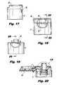
- FIG. 17is a side view of the closure of the present invention shown in FIGS. 11 through 16 , with the closure being shown in the closed position.
- FIG. 18is a front view of the closure of the present invention shown in FIGS. 11 through 17 , and illustrating the closure in the closed position.
- FIG. 19is a front view of the closure of the present invention shown in FIGS. 11 through 18 , with the lid portion of the closure being omitted from the figure.
- FIG. 20is a cross-sectional view of the closure of the present invention shown in FIGS. 11 through 19 , with the closure being shown in the open position.
- FIG. 21is a bottom plan view of the closure of the present invention shown in FIGS. 11 through 20 , with the closure being shown in the open position.
- FIG. 22is a cross-sectional view of the closure of the present invention shown in FIG. 18 , taken along line D-D of FIG. 18 .
- FIG. 23is a top plan view of a portion of the closure of the present invention shown in FIGS. 11 through 22 , and illustrating the closure in an open position.
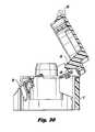
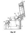
- FIGS. 24 through 33are cross-sectional views of the third embodiment of the closure of the present invention shown in FIGS. 11 through 23 , and illustrating in sequence the engagement of the various components of the closure that causes the lid portion of the closure to lift off the base portion to uncover the nozzle of the closure.
- FIGS. 1-10 of the drawingsThe one piece, push button, flip top closure of the present invention is illustrated by FIGS. 1-10 of the drawings.
- the first embodiment of the closure of the present inventionis illustrated by FIGS. 1 and 2 .
- the cylindrical base 2 of the closuredoes not include knurling 4 on its outer side wall 6 , as is included in the second embodiment of the present invention illustrated by FIGS. 3-10 of the drawings.
- the side wall 6 of the base 2 of the first embodiment of the closureincludes a substantially smooth surface.
- the first and second embodiments of the one piece, push button, flip top closure of the present inventionhave similar structure and, accordingly, both embodiments of the present invention will be described in detail together, with reference to FIGS. 1-10 of the drawings.
- a one piece, push button, flip top closure constructed in accordance with the present inventionincludes a base 2 which is generally cylindrical in shape, although other shapes, such as square, rectangular or oval, for the base are envisioned to be within the scope of the present invention.
- the cylindrical base 2may have its side wall 6 formed with or without knurling 4 , which knurling 4 provides a better grip for the closure if the closure is threadingly secured to the container and is desired to be removed therefrom.
- the knurling 4also provides a decorative feature to the closure of the present invention, although it is envisioned to be within the scope of the present invention to form the closure with other decorative features known to one skilled in the art.
- the cylindrical base 2includes a notch 8 formed through the thickness of the side wall 6 .
- the notch 8is provided to reveal or expose a finger engagement portion 10 (i.e., the push button) of a push button actuator 12 of the closure so that the push button actuator may be pressed by a user.
- the one piece, push button, flip top closure of the present inventionalso includes the push button actuator 12 , as mentioned above.
- the push button actuator 12is preferably in the form of a U-shaped member 14 that is twistingly joined to an inside surface of the cylindrical base 2 on opposite lateral sides of the actuator 12 . More specifically, the U-shaped member 14 is integrally molded to the base 2 and thus attached thereto by twist pin extensions 16 joining the inside surface of the cylindrical base 2 and the opposite lateral outer sides of the U-shaped member 14 . The U-shaped member 14 thus can partially rotate on the cylindrical base 2 , with the pin extensions 16 slightly twisting to permit such rotation.
- the U-shaped member 14 of the push button actuator 12includes on one side of the twist pin extensions 16 two spaced apart arms 18 . Each arm 18 includes a free end 20 , each free end 20 having an exposed edge 22 that engages the lid 24 to pivot the lid on the cylindrical base 2 .
- the U-shaped member 14also includes a finger engagement portion 10 situated on the opposite side of the twist pin extensions 16 .
- the finger engagement portion 10is in the form of a protrusion, which is also referred to herein as the push button, that is received by the notch 8 formed in the side wall 6 of the cylindrical base 2 and is exposed therethrough for the user to press with his or her finger to open the lid 24 of the closure.
- the one piece, push button, flip top closure of the present inventionalso includes a central cap 26 that is straddled by the spaced apart arms 18 of the U-shaped member 14 .
- the central cap 26is provided for mating with a container on which the closure is mounted and, in particular, the neck of the container.
- the central cap 26may includes threads (not shown) formed on an interior cylindrical wall 28 thereof, which threads would cooperate with the threaded neck of the container on which the closure is mounted. Alternatively, and as shown in FIG.
- the interior cylindrical wall 28 of the central cap 26may include tabs 30 extending outwardly from a radially inner surface thereof, which tabs 30 resiliently cooperate with a ring, shoulder or a lip (not shown) that may be provided on the neck of the container on which the closure is mounted. Accordingly, the closure of the present invention may be threadingly secured to the container and may be removed therefrom by unscrewing the closure from the container, or may be press-fitted onto and secured to the container and not removable therefrom.
- the central cap 26includes an orifice 32 formed centrally through the thickness thereof, the orifice 32 being provided to allow the contents of the container on which the closure is mounted to pass therethrough for use by the consumer.
- the orifice 32may be centered on a conical protrusion 34 formed on and extending from the upper surface of the top wall of the central cap 32 .
- the central cap 32may further include a cylindrical ring 36 situated concentrically within the interior wall 28 of the cap to help direct the contents of the container toward and through the orifice 32 of the central cap.
- the U-shaped member 14 of the push button actuator 12is twistingly joined to the central cap 26 by twist pin extensions 16 also extending between the lateral inner sides of the spaced apart arms 18 and the outer surface of the side wall of the central cap 26 so that the U-shaped member 14 partially rotates with respect to both the cylindrical base 2 and the central cap 26 .
- the central cap 26is rigidly joined to and integrally formed with the cylindrical base 2 , as is seen from FIGS. 2 and 4 of the drawings by a piece 38 connecting the central cap to the base.
- the one piece, push button, flip top closure of the present inventionalso includes a lid 24 .
- the lid 24includes a top wall 40 and a small side wall 42 joined peripherally to the top wall.
- the lid 24is pivotally mounted to the cylindrical base 2 . More specifically, a living hinge 44 connects an edge of the side wall 42 of the lid 24 to the side wall 6 of the cylindrical base 2 to allow the lid 24 to pivot with respect to the cylindrical base 2 .
- a strap hinge 46is also included and also has a living hinge 47 .
- the strap hinge 46extends from the upper surface of the top wall 40 of the lid to the outer surface of the side wall 6 of the cylindrical base 2 and is provided to maintain the lid 24 in an open position at preferably about one hundred, thirty-five degrees (135°) or some other obtuse angle defined between the top surface of the cylindrical base 2 and the bottom surface of the top wall of the lid 24 .
- This particular angleis preferred, as the closure, when in the open position, has its lid 24 positioned sufficiently away from the cylindrical base 2 and orifice 32 of the central cap 26 so as not to interfere with the dispensing of the contents of the container through the closure orifice.
- the top wall 40 of the lid 24is substantially planar, although it may include a central conical protrusion 48 extending outwardly from the top surface thereof and a complementary conical indentation or recess 50 formed in the lower surface thereof.
- the recess 50is provided to receive the conically shaped portion 34 of the top surface of the central cap 26 and so as to allow the lid 24 to be closely received on the central cap 26 , with the side wall 42 of the lid closely engaging and resting on the top surface of the cylindrical base 2 .
- a cutout 52is formed in the top wall 40 of the lid and over a portion of the lid side wall 42 , which cutout 52 is aligned with the notch 8 formed in the side wall 6 of the cylindrical base 2 when the lid 24 is in the closed position and resting on the top surface of the cylindrical base.
- the cutout 52which extends partially radially and partially circumferentially on the top wall 40 of the lid, exposes the finger engagement portion 10 of the push button actuator 12 so that a user may press the push button to pivot the lid 24 with respect to the cylindrical base 2 .
- the lid 24is further formed with a boss 54 extending outwardly from the lower surface of the top wall 40 thereof, and more particularly, from the conical recess 50 formed in the lower surface thereof.
- the boss 54is dimensioned so that it may be closely received by the orifice 32 to seal the orifice formed in the central cap 26 and to prevent the contents of the container on which the closure is mounted from being inadvertently dispensed.
- the boss 54may have a rounded or beveled edge, or may itself be conically shaped, so as to facilitate its proper seating within the orifice 32 of the central cap and to allow the lid 24 to freely pivot on the cylindrical base 2 even if there is a build up of material or residue of the container contents surrounding the orifice 32 of the central cap 26 .
- the lidfurther includes a pair of camming protrusions 56 extending outwardly from the lower surface of the lid top wall 40 .
- the camming protrusions 56are spaced apart from one another and aligned with the free end edges 22 of the spaced apart arms 18 of the U-shaped member 14 .
- the camming protrusions 56have curved camming surfaces 58 which are engaged by the spaced apart arms 18 of the U-shaped member when the push button actuator 12 is forced to partially rotate on the cylindrical base 2 .
- a userpresses on the finger engagement portion 10 of the push button actuator 12 at the notch 10 formed in the cylindrical base side wall 6 and the cutout 52 formed in the top wall 40 of the lid.
- Pressure on the finger engagement portion 10causes the push button actuator 12 to twistingly rotate on the cylindrical base 2 , causing the two spaced apart arms 18 to lift and engage at its free end edges 22 the camming protrusions 56 of the lid.
- This engagement between the push button actuator 12 and the camming protrusions 56forces the lid 24 to pivot with respect to the cylindrical base 2 to a particular angle at which the strap hinge 46 pulls the lid open further to the non-interfering, obtuse angle shown in FIG.
- finger pressureis exerted on the lid 24 to pivot the lid toward the cylindrical base 2 .
- the camming protrusions 56 on the lidengage the free end edges 22 of the spaced apart arms 18 of the push button actuator 12 , forcing the push button actuator 12 to twist on the cylindrical base 2 to its original position, with the finger engagement portion 10 again residing in the notch 8 and cutout 52 respectively formed in the cylindrical base side wall 6 and lid top wall 40 , and with the boss 54 being again received by the orifice 32 formed in the central cap 26 to seal the orifice and to prevent the contents of the container on which the closure of the present invention is mounted from being inadvertently dispensed.
- a unique feature of the closure of the present inventionis that it is injection molded as one continuous piece, which simplifies the manufacturing process and eliminates or minimizes any labor in assembling the closure.
- the closuremay also be formed by using bi-injection molding technology to yield a two color closure, where certain components, such as the push button actuator 12 and the remainder of the closure, are provided in different colors.
- the closure of the present inventionmay be designed to have either a snap-on or threaded cylindrical base 2 , as described previously, providing the closure with greater flexibility to work with plastic bottles, tottles, tubes or other containers having threaded necks or other structural features for attaching the closure to the container.
- the closure of the present inventionmay also be designed to have flat top surface on its lid 24 rather than the conical surface shown in FIG. 3 to allow the container to rest in an inverted position on the closure. This inverted stance allows the contents in the container to drain towards the closure, facilitating the evacuation of a partially filled container.
- the push button actuator 12need not specifically be in the form of the U-shaped member 14 described previously, and it is envisioned to be within the scope of the present invention to form the push button actuator 12 in other shapes and configurations to force the lid 24 to pivot on the base 2 when the actuator 12 is pressed by the user.
- the closure of the present inventionmay also be designed to be “tamper evident”. This could be achieved by adding thin “tabs” (not shown) to hold the push button actuator 12 , and in particular the finger engagement portion 10 thereof, in place. The consumer would break such tabs by pressing on the push button actuator 12 when the closure is first used.
- FIGS. 11-33illustrate a third embodiment of the closure of the present invention, and its operation.
- This third embodimentis similar in structure and operation to the first and second embodiments described previously and shown in FIGS. 1-10 .
- one modificationincludes adding an internal wall 70 to obscure from the viewer the mechanism for lifting the lid portion 24 of the closure off the base portion 2 .
- That internal wall 70extends outwardly perpendicularly from the underside surface of the lid 24 , and preferably extends to the top surface of the base 2 when the lid is properly seated on the base in the closed position.
- FIGS. 11-30Another feature of the third embodiment of the present invention shown in FIGS. 11-30 is the inclusion of a nozzle 72 protruding outwardly perpendicularly from the upper surface of the base 2 , and more preferably, from the upper surface of the central cap 26 , which nozzle 72 has a beveled or sloped edge 74 that is received in a complementary shaped recessed boss 76 extending from the underside of the lid and aligned with the nozzle 72 of the base. Furthermore, the base 2 includes an interiorly threaded portion 78 which defines a passageway that communicates with the opening or bore 80 of the nozzle 72 to allow the passage of fluid or materials therethrough.
- the interiorly threaded portion 78may be screwed on to the threaded neck of a container, such as a toothpaste container, for example, so that the contents of the container may pass through the base 2 and nozzle 72 , as desired by the user, when the closure is mounted on the container.
- a containersuch as a toothpaste container
- each of the spaced apart arms 18 of the push button actuator 12includes a flat surface 81 which engages the curved camming surface 58 of a respective camming protrusion 56 .
- the spaced apart armspreferably included sloped or ramped surfaces 82 that extend to the exposed ends 22 of the arms.
- the surfaces 81are substantially flat.
- the arms 18on their underside and situated below surfaces 81 , preferably include stiffening ribs 84 to add strength to the arms to engage the camming protrusions 56 of the lid with minimal or no deflection of the arms.
- the camming surface 58has a more curved, convex profile, as opposed to the concave profile of the camming surface 58 of the embodiment shown in FIG. 2 .
- the overall height of the closuremeasured from the lower edge of the base 2 to the upper surface of the lid 24 , has been increased in this third embodiment, preferably by about 0.200 inches, to add a “back finger support” to allow the user to wrap his index finger partially about, and engage, the wall of the base 2 situated diametrically opposite the finger engagement portion 10 while he depresses the finger engagement portion with his thumb.
- This added height to the base 2facilitates the user in grasping the closure with his hand in order to open the lid by using the finger engagement portion.
- the threaded portion 78 of the nozzle 72has also been lengthened in this third embodiment preferably by about 0.200 inches.
- the two “support” hinges 38have been changed to a “butterfly” design to reduce or eliminate any sharp edges that would have protruded outwardly from the periphery of the closure.
Landscapes
- Engineering & Computer Science (AREA)
- Mechanical Engineering (AREA)
- Closures For Containers (AREA)
- Push-Button Switches (AREA)
- Switches With Compound Operations (AREA)
- Casings For Electric Apparatus (AREA)
- Fire-Detection Mechanisms (AREA)
- Electric Clocks (AREA)
Abstract
Description
Claims (9)
Priority Applications (9)
| Application Number | Priority Date | Filing Date | Title |
|---|---|---|---|
| US11/820,159US8434639B2 (en) | 2006-06-19 | 2007-06-18 | One piece, push button, flip top closure |
| EP07809663AEP2035292B1 (en) | 2006-06-19 | 2007-06-19 | One piece, push button, flip top closure |
| PCT/US2007/014242WO2007149419A2 (en) | 2006-06-19 | 2007-06-19 | One piece, push button, flip top closure |
| MX2008016242AMX2008016242A (en) | 2006-06-19 | 2007-06-19 | One piece, push button, flip top closure. |
| AT07809663TATE469043T1 (en) | 2006-06-19 | 2007-06-19 | ONE-PIECE HINGED LID CLOSURE WITH PRESS BUTTON |
| PL10156121TPL2189386T3 (en) | 2006-06-19 | 2007-06-19 | One piece, push button, flip top closure |
| DE602007006804TDE602007006804D1 (en) | 2006-06-19 | 2007-06-19 | ONE PIECE FLIP COVER WITH PRESSURE KNOB |
| EP10156121.5AEP2189386B1 (en) | 2006-06-19 | 2007-06-19 | One piece, push button, flip top closure |
| CN2007800227507ACN101472804B (en) | 2006-06-19 | 2007-06-19 | Integral push-button flip-top closure |
Applications Claiming Priority (3)
| Application Number | Priority Date | Filing Date | Title |
|---|---|---|---|
| US81483606P | 2006-06-19 | 2006-06-19 | |
| US91921307P | 2007-03-21 | 2007-03-21 | |
| US11/820,159US8434639B2 (en) | 2006-06-19 | 2007-06-18 | One piece, push button, flip top closure |
Publications (2)
| Publication Number | Publication Date |
|---|---|
| US20080023477A1 US20080023477A1 (en) | 2008-01-31 |
| US8434639B2true US8434639B2 (en) | 2013-05-07 |
Family
ID=38834058
Family Applications (1)
| Application Number | Title | Priority Date | Filing Date |
|---|---|---|---|
| US11/820,159Expired - Fee RelatedUS8434639B2 (en) | 2006-06-19 | 2007-06-18 | One piece, push button, flip top closure |
Country Status (8)
| Country | Link |
|---|---|
| US (1) | US8434639B2 (en) |
| EP (2) | EP2035292B1 (en) |
| CN (1) | CN101472804B (en) |
| AT (1) | ATE469043T1 (en) |
| DE (1) | DE602007006804D1 (en) |
| MX (1) | MX2008016242A (en) |
| PL (1) | PL2189386T3 (en) |
| WO (1) | WO2007149419A2 (en) |
Cited By (42)
| Publication number | Priority date | Publication date | Assignee | Title |
|---|---|---|---|---|
| WO2015017306A1 (en)* | 2013-07-31 | 2015-02-05 | Msd Consumer Care, Inc. | Actuator assembly for a pressurized plastic vessel |
| US9327884B2 (en) | 2014-07-14 | 2016-05-03 | Gene R. Stull, SR. | Child-resistant flip-top closure |
| US20160227902A1 (en)* | 2015-02-04 | 2016-08-11 | Sillage Llc | Fragrance bottle assembly |
| US9828146B2 (en) | 2014-06-24 | 2017-11-28 | Stefan LOUKOV | Tamper evident flip-top closure, method and tool for making the same |
| US10138035B2 (en) | 2014-06-24 | 2018-11-27 | Stefan LOUKOV | Tamper evident flip-top closure, method and tool for making the same |
| US10183112B2 (en) | 2013-08-30 | 2019-01-22 | Hollister Incorporated | Device for trans anal irrigation |
| US10561817B2 (en) | 2014-05-30 | 2020-02-18 | Hollister Incorporated | Flip open catheter package |
| US10736825B2 (en) | 2012-09-27 | 2020-08-11 | Beiersdorf Ag | Foaming skincare formulations |
| US10737013B2 (en) | 2014-07-08 | 2020-08-11 | Hollister Incorporated | Portable trans anal irrigation device |
| US10765796B2 (en) | 2014-07-08 | 2020-09-08 | Hollister Incorporated | Trans anal irrigation platform with bed module |
| USD920046S1 (en) | 2019-05-23 | 2021-05-25 | Camelbak Products, Llc | Container cap with drink vessel |
| US11020561B2 (en) | 2016-04-22 | 2021-06-01 | Hollister Incorporated | Medical device package with a twist cap |
| US11040809B1 (en) | 2020-10-09 | 2021-06-22 | Packaging Concepts Associates Holding, Inc. | Push button tilt top closure and locking system for a container |
| US11059633B2 (en) | 2019-10-31 | 2021-07-13 | Cheer Pack North America | Flip-top closure for container |
| US11103676B2 (en) | 2016-04-22 | 2021-08-31 | Hollister Incorporated | Medical device package with flip cap having a snap fit |
| US11267438B1 (en)* | 2021-02-02 | 2022-03-08 | Teddy Presher | Kidnapping notification system |
| US11383021B2 (en) | 2016-07-08 | 2022-07-12 | Hollister Incorporated | Wireless electronic pump design for a body cavity irrigation device |
| US11396408B2 (en) | 2019-08-05 | 2022-07-26 | Yeti Coolers, Llc | Lid for container |
| US11497844B2 (en) | 2016-12-14 | 2022-11-15 | Hollister Incorporated | Transanal irrigation device and system |
| US11634314B1 (en) | 2022-11-17 | 2023-04-25 | Sharkninja Operating Llc | Dosing accuracy |
| US11647860B1 (en) | 2022-05-13 | 2023-05-16 | Sharkninja Operating Llc | Flavored beverage carbonation system |
| US11666730B2 (en) | 2017-12-08 | 2023-06-06 | Hollister Incorporated | Package for medical device for ergonomic device removal |
| US11707599B2 (en) | 2017-02-21 | 2023-07-25 | Hollister Incorporated | Medical device package with twist-off cap |
| US11738988B1 (en) | 2022-11-17 | 2023-08-29 | Sharkninja Operating Llc | Ingredient container valve control |
| US11745996B1 (en) | 2022-11-17 | 2023-09-05 | Sharkninja Operating Llc | Ingredient containers for use with beverage dispensers |
| US11751585B1 (en) | 2022-05-13 | 2023-09-12 | Sharkninja Operating Llc | Flavored beverage carbonation system |
| US11771865B2 (en) | 2017-10-25 | 2023-10-03 | Hollister Incorporated | Caps for catheter packages |
| USD1005776S1 (en) | 2021-09-15 | 2023-11-28 | Yeti Coolers, Llc | Lid |
| US11871867B1 (en) | 2023-03-22 | 2024-01-16 | Sharkninja Operating Llc | Additive container with bottom cover |
| USD1011136S1 (en) | 2020-10-27 | 2024-01-16 | Yeti Coolers, Llc | Bottle |
| US11925287B1 (en) | 2023-03-22 | 2024-03-12 | Sharkninja Operating Llc | Additive container with inlet tube |
| US12005408B1 (en) | 2023-04-14 | 2024-06-11 | Sharkninja Operating Llc | Mixing funnel |
| USD1036936S1 (en) | 2021-10-26 | 2024-07-30 | Yeti Coolers, Llc | Bottle |
| US12084334B2 (en) | 2022-11-17 | 2024-09-10 | Sharkninja Operating Llc | Ingredient container |
| US12096880B2 (en) | 2022-05-13 | 2024-09-24 | Sharkninja Operating Llc | Flavorant for beverage carbonation system |
| US12103840B2 (en) | 2022-11-17 | 2024-10-01 | Sharkninja Operating Llc | Ingredient container with sealing valve |
| US12116257B1 (en) | 2023-03-22 | 2024-10-15 | Sharkninja Operating Llc | Adapter for beverage dispenser |
| US12213617B2 (en) | 2022-05-13 | 2025-02-04 | Sharkninja Operating Llc | Flavored beverage carbonation process |
| USD1075411S1 (en) | 2022-10-26 | 2025-05-20 | Yeti Coolers, Llc | Bottle |
| USD1091308S1 (en) | 2022-12-23 | 2025-09-02 | Sharkninja Operating Llc | Ingredient container |
| USD1092208S1 (en) | 2022-12-23 | 2025-09-09 | Sharkninja Operating Llc | Cap of ingredient container |
| US12433709B2 (en) | 2020-09-04 | 2025-10-07 | Hollister Incorporated | Medical device package with first use indicator label |
Families Citing this family (27)
| Publication number | Priority date | Publication date | Assignee | Title |
|---|---|---|---|---|
| FR2924097A1 (en)* | 2007-03-26 | 2009-05-29 | Lindal France Soc Par Actions | CAP FOR SPRAYER. |
| US20080245795A1 (en)* | 2007-04-05 | 2008-10-09 | Berge Gary L | Auto open closure |
| JP4276283B1 (en)* | 2008-02-04 | 2009-06-10 | エム・エフ・ヴィ株式会社 | cap |
| MX2011001336A (en)* | 2008-08-05 | 2011-03-15 | Ctl Th Packaging S L Unipersonal | Closure device comprising a measuring cap, intended to be connected to a flexible container. |
| US8556137B2 (en) | 2009-02-23 | 2013-10-15 | Gateway Plastics, Inc. | Closure for a container |
| MX344251B (en)* | 2011-09-02 | 2016-12-09 | Essel Propack Ltd | Tamper-evident closure. |
| DE102011112615A1 (en) | 2011-09-08 | 2013-03-14 | Krallmann Kunststoffverarbeitung Gmbh | Flip top cap |
| DE102011112616A1 (en) | 2011-09-08 | 2013-03-14 | Krallmann Kunststoffverarbeitung Gmbh | Flip top cap |
| CA2860643C (en)* | 2012-03-20 | 2019-07-30 | Csp Technologies, Inc. | Dispenser |
| JP5756873B2 (en)* | 2013-12-06 | 2015-07-29 | 三菱製鋼株式会社 | Switchgear |
| EP3110713B1 (en)* | 2014-02-28 | 2017-10-18 | Silvia Ferrari | Reclosable stopper revealing a first opening |
| JP6327458B2 (en)* | 2014-05-30 | 2018-05-23 | 株式会社吉野工業所 | Two-material hinge cap |
| JP6027647B1 (en)* | 2015-06-16 | 2016-11-16 | サーモス株式会社 | Cap unit and beverage container |
| US11064711B2 (en)* | 2015-08-27 | 2021-07-20 | Societe Des Produits Nestle S.A. | Closures for liquid-dispensing containers and methods for making and using such closures |
| FR3055531B1 (en)* | 2016-09-08 | 2018-08-31 | L'oreal | CLOSURE CAPSULE |
| US11040806B2 (en) | 2017-12-15 | 2021-06-22 | Husky Injection Molding Systems Ltd. | Closure cap for a container |
| WO2019147260A1 (en)* | 2018-01-26 | 2019-08-01 | Aptargroup, Inc. | Closure for a container |
| US11292642B2 (en) | 2018-12-21 | 2022-04-05 | H. J. Heinz Company Brands Llc | Container, closure, and methods for manufacture |
| USD889260S1 (en) | 2018-12-21 | 2020-07-07 | H.J. Heinz Company Brands Llc | Closure for a container |
| ES2934509T3 (en) | 2018-12-21 | 2023-02-22 | Heinz Co Brands H J Llc | Container, closure and methods of manufacture |
| CN114423683B (en)* | 2019-07-27 | 2024-12-06 | 这个瓶盖有限公司 | Lids for containers |
| US11891218B2 (en) | 2019-09-20 | 2024-02-06 | H.J. Heinz Company Brands Llc | Container, closure, and methods for manufacture |
| USD926577S1 (en)* | 2019-09-23 | 2021-08-03 | Verdant Ventures | Tamper-resistant lid assembly |
| WO2021174335A1 (en) | 2020-03-03 | 2021-09-10 | Husky Injection Molding Systems Ltd. | Closure |
| US20230117474A1 (en)* | 2020-03-24 | 2023-04-20 | Husky Injection Molding Systems Ltd. | Closure device for a container |
| USD939960S1 (en) | 2020-04-09 | 2022-01-04 | Husky Injection Molding Systems Ltd. | Closure cap |
| JP7540716B2 (en) | 2021-02-17 | 2024-08-27 | パール金属株式会社 | Portable beverage container cap |
Citations (7)
| Publication number | Priority date | Publication date | Assignee | Title |
|---|---|---|---|---|
| US1131774A (en) | 1914-01-28 | 1915-03-16 | Linford J Davis | Receptacle support and cover operating and locking means. |
| US5143234A (en) | 1991-08-12 | 1992-09-01 | Zeller Closures, Inc. | Single walled dispensing closures with positive alignment means |
| US5573127A (en)* | 1995-05-16 | 1996-11-12 | Nifco, Inc. | Cap for liquid containers |
| EP0819615A1 (en) | 1994-08-05 | 1998-01-21 | Nifco Inc. | Container cap including a primary cap and a secondary cap joined by a hinge |
| FR2849429A1 (en) | 2002-12-31 | 2004-07-02 | Plastohm Sa | Flask opening and closing device, has closing shutter with controlled opening unit to assure complete tilting of shutter in opening, according to constant force value and movement applied to shutter |
| US6834769B2 (en)* | 2000-09-04 | 2004-12-28 | M.F.V Co., Ltd. | Hinge cap |
| US7000792B2 (en) | 2004-03-31 | 2006-02-21 | Takemoto Yoki Co., Ltd. | Self-opening cap mechanism |
Family Cites Families (2)
| Publication number | Priority date | Publication date | Assignee | Title |
|---|---|---|---|---|
| CN2222691Y (en)* | 1994-01-14 | 1996-03-20 | 上海电表模具厂象山分厂 | Plastic tube cover |
| CN2350327Y (en)* | 1998-11-20 | 1999-11-24 | 上海家化有限公司 | Joined combined elastic cap |
- 2007
- 2007-06-18USUS11/820,159patent/US8434639B2/ennot_activeExpired - Fee Related
- 2007-06-19EPEP07809663Apatent/EP2035292B1/ennot_activeNot-in-force
- 2007-06-19CNCN2007800227507Apatent/CN101472804B/ennot_activeExpired - Fee Related
- 2007-06-19DEDE602007006804Tpatent/DE602007006804D1/enactiveActive
- 2007-06-19EPEP10156121.5Apatent/EP2189386B1/ennot_activeNot-in-force
- 2007-06-19MXMX2008016242Apatent/MX2008016242A/enactiveIP Right Grant
- 2007-06-19ATAT07809663Tpatent/ATE469043T1/ennot_activeIP Right Cessation
- 2007-06-19PLPL10156121Tpatent/PL2189386T3/enunknown
- 2007-06-19WOPCT/US2007/014242patent/WO2007149419A2/enactiveApplication Filing
Patent Citations (8)
| Publication number | Priority date | Publication date | Assignee | Title |
|---|---|---|---|---|
| US1131774A (en) | 1914-01-28 | 1915-03-16 | Linford J Davis | Receptacle support and cover operating and locking means. |
| US5143234A (en) | 1991-08-12 | 1992-09-01 | Zeller Closures, Inc. | Single walled dispensing closures with positive alignment means |
| EP0819615A1 (en) | 1994-08-05 | 1998-01-21 | Nifco Inc. | Container cap including a primary cap and a secondary cap joined by a hinge |
| US5573127A (en)* | 1995-05-16 | 1996-11-12 | Nifco, Inc. | Cap for liquid containers |
| US6834769B2 (en)* | 2000-09-04 | 2004-12-28 | M.F.V Co., Ltd. | Hinge cap |
| FR2849429A1 (en) | 2002-12-31 | 2004-07-02 | Plastohm Sa | Flask opening and closing device, has closing shutter with controlled opening unit to assure complete tilting of shutter in opening, according to constant force value and movement applied to shutter |
| US20060151416A1 (en) | 2002-12-31 | 2006-07-13 | Pascal Hennemann | Closure cap for a bottle with controlled opening |
| US7000792B2 (en) | 2004-03-31 | 2006-02-21 | Takemoto Yoki Co., Ltd. | Self-opening cap mechanism |
Non-Patent Citations (3)
| Title |
|---|
| European Search Report dated Jun. 17, 2009 (six pages). |
| International Preliminary Report on Patentability, Mar. 7, 2008. |
| Notification Concerning Transmittal of International Preliminary Report on Patentability (Chapter I of the Patent Cooperation Treaty). |
Cited By (63)
| Publication number | Priority date | Publication date | Assignee | Title |
|---|---|---|---|---|
| US10736825B2 (en) | 2012-09-27 | 2020-08-11 | Beiersdorf Ag | Foaming skincare formulations |
| US11247839B2 (en) | 2013-07-31 | 2022-02-15 | Beiersdorf Ag | Oversized actuator and actuator assembly for a pressurized plastic vessel |
| WO2015017306A1 (en)* | 2013-07-31 | 2015-02-05 | Msd Consumer Care, Inc. | Actuator assembly for a pressurized plastic vessel |
| US11116891B2 (en) | 2013-08-30 | 2021-09-14 | Hollister Incorporated | Device for trans anal irrigation |
| US10183112B2 (en) | 2013-08-30 | 2019-01-22 | Hollister Incorporated | Device for trans anal irrigation |
| US11534573B2 (en) | 2014-05-30 | 2022-12-27 | Hollister Incorporated | Flip open catheter package |
| US10561817B2 (en) | 2014-05-30 | 2020-02-18 | Hollister Incorporated | Flip open catheter package |
| US9828146B2 (en) | 2014-06-24 | 2017-11-28 | Stefan LOUKOV | Tamper evident flip-top closure, method and tool for making the same |
| US10138035B2 (en) | 2014-06-24 | 2018-11-27 | Stefan LOUKOV | Tamper evident flip-top closure, method and tool for making the same |
| US10737013B2 (en) | 2014-07-08 | 2020-08-11 | Hollister Incorporated | Portable trans anal irrigation device |
| US10765796B2 (en) | 2014-07-08 | 2020-09-08 | Hollister Incorporated | Trans anal irrigation platform with bed module |
| US11497845B2 (en) | 2014-07-08 | 2022-11-15 | Hollister Incorporated | Trans anal irrigation platform with bed module |
| US9327884B2 (en) | 2014-07-14 | 2016-05-03 | Gene R. Stull, SR. | Child-resistant flip-top closure |
| US20160227902A1 (en)* | 2015-02-04 | 2016-08-11 | Sillage Llc | Fragrance bottle assembly |
| US11207701B2 (en) | 2015-02-04 | 2021-12-28 | Sillage Llc | Fragrance bottle assembly |
| US11103676B2 (en) | 2016-04-22 | 2021-08-31 | Hollister Incorporated | Medical device package with flip cap having a snap fit |
| US11833312B2 (en) | 2016-04-22 | 2023-12-05 | Hollister Incorporated | Medical device package with flip cap having a snap fit |
| US12128191B2 (en) | 2016-04-22 | 2024-10-29 | Hollister Incorporated | Medical device package with a twist cap |
| US12290641B2 (en) | 2016-04-22 | 2025-05-06 | Hollister Incorporated | Medical device package with flip cap having a snap fit |
| US11813409B2 (en) | 2016-04-22 | 2023-11-14 | Hollister Incorporated | Medical device package with flip cap having a snap fit |
| US11020561B2 (en) | 2016-04-22 | 2021-06-01 | Hollister Incorporated | Medical device package with a twist cap |
| US11383021B2 (en) | 2016-07-08 | 2022-07-12 | Hollister Incorporated | Wireless electronic pump design for a body cavity irrigation device |
| US11497844B2 (en) | 2016-12-14 | 2022-11-15 | Hollister Incorporated | Transanal irrigation device and system |
| US11707599B2 (en) | 2017-02-21 | 2023-07-25 | Hollister Incorporated | Medical device package with twist-off cap |
| US12144935B2 (en) | 2017-02-21 | 2024-11-19 | Hollister Incorporated | Medical device package with flip cap having a snap fit |
| US12171954B2 (en) | 2017-10-25 | 2024-12-24 | Hollister Incorporated | Caps for catheter packages |
| US11771865B2 (en) | 2017-10-25 | 2023-10-03 | Hollister Incorporated | Caps for catheter packages |
| US12023452B2 (en) | 2017-12-08 | 2024-07-02 | Hollister Incorporated | Package for medical device for ergonomic device removal |
| US11666730B2 (en) | 2017-12-08 | 2023-06-06 | Hollister Incorporated | Package for medical device for ergonomic device removal |
| USD920046S1 (en) | 2019-05-23 | 2021-05-25 | Camelbak Products, Llc | Container cap with drink vessel |
| US11396408B2 (en) | 2019-08-05 | 2022-07-26 | Yeti Coolers, Llc | Lid for container |
| US11059633B2 (en) | 2019-10-31 | 2021-07-13 | Cheer Pack North America | Flip-top closure for container |
| US12433709B2 (en) | 2020-09-04 | 2025-10-07 | Hollister Incorporated | Medical device package with first use indicator label |
| US11040809B1 (en) | 2020-10-09 | 2021-06-22 | Packaging Concepts Associates Holding, Inc. | Push button tilt top closure and locking system for a container |
| USD1076592S1 (en) | 2020-10-27 | 2025-05-27 | Yeti Coolers, Llc | Lid |
| USD1011136S1 (en) | 2020-10-27 | 2024-01-16 | Yeti Coolers, Llc | Bottle |
| US11780406B2 (en)* | 2021-02-02 | 2023-10-10 | Teddy Presher | Kidnapping notification system |
| US20220242365A1 (en)* | 2021-02-02 | 2022-08-04 | Teddy Presher | Kidnapping notification system |
| US11267438B1 (en)* | 2021-02-02 | 2022-03-08 | Teddy Presher | Kidnapping notification system |
| USD1067772S1 (en) | 2021-09-15 | 2025-03-25 | Yeti Coolers, Llc | Lid |
| USD1005776S1 (en) | 2021-09-15 | 2023-11-28 | Yeti Coolers, Llc | Lid |
| USD1015804S1 (en) | 2021-09-15 | 2024-02-27 | Yeti Coolers, Llc | Lid |
| USD1036936S1 (en) | 2021-10-26 | 2024-07-30 | Yeti Coolers, Llc | Bottle |
| US12096880B2 (en) | 2022-05-13 | 2024-09-24 | Sharkninja Operating Llc | Flavorant for beverage carbonation system |
| US11751585B1 (en) | 2022-05-13 | 2023-09-12 | Sharkninja Operating Llc | Flavored beverage carbonation system |
| US11647860B1 (en) | 2022-05-13 | 2023-05-16 | Sharkninja Operating Llc | Flavored beverage carbonation system |
| US12213617B2 (en) | 2022-05-13 | 2025-02-04 | Sharkninja Operating Llc | Flavored beverage carbonation process |
| USD1075411S1 (en) | 2022-10-26 | 2025-05-20 | Yeti Coolers, Llc | Bottle |
| USD1077578S1 (en) | 2022-10-26 | 2025-06-03 | Yeti Coolers, Llc | Bottle |
| US12084334B2 (en) | 2022-11-17 | 2024-09-10 | Sharkninja Operating Llc | Ingredient container |
| US12122661B2 (en) | 2022-11-17 | 2024-10-22 | Sharkninja Operating Llc | Ingredient container valve control |
| US11634314B1 (en) | 2022-11-17 | 2023-04-25 | Sharkninja Operating Llc | Dosing accuracy |
| US12103840B2 (en) | 2022-11-17 | 2024-10-01 | Sharkninja Operating Llc | Ingredient container with sealing valve |
| US12006202B1 (en) | 2022-11-17 | 2024-06-11 | Sharkninja Operating Llc | Ingredient container valve control |
| US11745996B1 (en) | 2022-11-17 | 2023-09-05 | Sharkninja Operating Llc | Ingredient containers for use with beverage dispensers |
| US11738988B1 (en) | 2022-11-17 | 2023-08-29 | Sharkninja Operating Llc | Ingredient container valve control |
| US12410048B2 (en) | 2022-11-17 | 2025-09-09 | Sharkninja Operating Llc | Ingredient container |
| USD1091308S1 (en) | 2022-12-23 | 2025-09-02 | Sharkninja Operating Llc | Ingredient container |
| USD1092208S1 (en) | 2022-12-23 | 2025-09-09 | Sharkninja Operating Llc | Cap of ingredient container |
| US12116257B1 (en) | 2023-03-22 | 2024-10-15 | Sharkninja Operating Llc | Adapter for beverage dispenser |
| US11925287B1 (en) | 2023-03-22 | 2024-03-12 | Sharkninja Operating Llc | Additive container with inlet tube |
| US11871867B1 (en) | 2023-03-22 | 2024-01-16 | Sharkninja Operating Llc | Additive container with bottom cover |
| US12005408B1 (en) | 2023-04-14 | 2024-06-11 | Sharkninja Operating Llc | Mixing funnel |
Also Published As
| Publication number | Publication date |
|---|---|
| EP2035292A2 (en) | 2009-03-18 |
| CN101472804B (en) | 2011-09-14 |
| CN101472804A (en) | 2009-07-01 |
| MX2008016242A (en) | 2009-02-17 |
| PL2189386T3 (en) | 2015-05-29 |
| DE602007006804D1 (en) | 2010-07-08 |
| US20080023477A1 (en) | 2008-01-31 |
| EP2189386B1 (en) | 2014-12-10 |
| WO2007149419A3 (en) | 2008-05-08 |
| EP2035292A4 (en) | 2009-07-15 |
| EP2189386A1 (en) | 2010-05-26 |
| WO2007149419A2 (en) | 2007-12-27 |
| EP2035292B1 (en) | 2010-05-26 |
| ATE469043T1 (en) | 2010-06-15 |
Similar Documents
| Publication | Publication Date | Title |
|---|---|---|
| US8434639B2 (en) | One piece, push button, flip top closure | |
| US5273177A (en) | Press-to-open dispensing closure | |
| AU763490B2 (en) | Dispenser package for fluent products and method of manufacture | |
| US4087028A (en) | Snap lock dispensing cap | |
| US6691901B2 (en) | Closure for a container | |
| US4558806A (en) | Condiment cap | |
| US4923085A (en) | Container with pressure-release lid | |
| US4568005A (en) | Snap-on closure for bottles | |
| US6923347B2 (en) | Assembly for packaging a product, especially a cosmetic product | |
| US20070095864A1 (en) | Dispensing closure for containers | |
| EP1700791A2 (en) | System including a hinged closure and tube container and method for sealing a hinged closure on a tube container | |
| US4632266A (en) | Container cap | |
| US20030071041A1 (en) | Closure for a container | |
| US5065877A (en) | Container with lid | |
| NZ565498A (en) | Dispensing hinged closure made in one piece with a snap latch | |
| EP0473678A1 (en) | Spout for flasks and similar receptacles, with a piercing element for piercing a lid on receptacle necks. | |
| WO1999037190A1 (en) | Bottle convertible into drinking utensil | |
| US5551607A (en) | Dispensing cap with leveraged pivot trigger | |
| EA019743B1 (en) | Toggle-action dispensing closure with articulated rear flange | |
| HU216533B (en) | Container with closure cap and cap | |
| EP1622815B1 (en) | Closure element for cosmetic product containers and the like | |
| WO2022069964A1 (en) | Hinged closure | |
| US5961010A (en) | Dispensing beverage closure | |
| US7051894B2 (en) | Circular dispensing container with a hinged lid | |
| US20020170915A1 (en) | Closure with secondary compartment |
Legal Events
| Date | Code | Title | Description |
|---|---|---|---|
| AS | Assignment | Owner name:C&N PACKAGING, INC., NEW YORK Free format text:ASSIGNMENT OF ASSIGNORS INTEREST;ASSIGNOR:MARKET, BROOKS R.;REEL/FRAME:019835/0991 Effective date:20070815 | |
| AS | Assignment | Owner name:C&N PACKAGING, INC., NEW YORK Free format text:CORRECTIVE ASSIGNMENT TO CORRECT THE CONVEYING PARTY DATA;ASSIGNOR:MARKERT, BROOKS R.;REEL/FRAME:019839/0293 Effective date:20070815 Owner name:C&N PACKAGING, INC., NEW YORK Free format text:CORRECTIVE ASSIGNMENT TO CORRECT THE CONVEYING PARTY DATA: LAST NAME PREVIOUSLY RECORDED ON REEL 019835 FRAME 0991. ASSIGNOR(S) HEREBY CONFIRMS THE ASSIGNMENT;ASSIGNOR:MARKERT, BROOKS R.;REEL/FRAME:019839/0293 Effective date:20070815 | |
| STCF | Information on status: patent grant | Free format text:PATENTED CASE | |
| FEPP | Fee payment procedure | Free format text:PAT HOLDER NO LONGER CLAIMS SMALL ENTITY STATUS, ENTITY STATUS SET TO UNDISCOUNTED (ORIGINAL EVENT CODE: STOL); ENTITY STATUS OF PATENT OWNER: LARGE ENTITY | |
| FPAY | Fee payment | Year of fee payment:4 | |
| FEPP | Fee payment procedure | Free format text:MAINTENANCE FEE REMINDER MAILED (ORIGINAL EVENT CODE: REM.); ENTITY STATUS OF PATENT OWNER: LARGE ENTITY | |
| LAPS | Lapse for failure to pay maintenance fees | Free format text:PATENT EXPIRED FOR FAILURE TO PAY MAINTENANCE FEES (ORIGINAL EVENT CODE: EXP.); ENTITY STATUS OF PATENT OWNER: LARGE ENTITY | |
| STCH | Information on status: patent discontinuation | Free format text:PATENT EXPIRED DUE TO NONPAYMENT OF MAINTENANCE FEES UNDER 37 CFR 1.362 | |
| FP | Lapsed due to failure to pay maintenance fee | Effective date:20210507 |