US8434489B2 - Contraceptive devices and methods - Google Patents
Contraceptive devices and methodsDownload PDFInfo
- Publication number
- US8434489B2 US8434489B2US12/605,304US60530409AUS8434489B2US 8434489 B2US8434489 B2US 8434489B2US 60530409 AUS60530409 AUS 60530409AUS 8434489 B2US8434489 B2US 8434489B2
- Authority
- US
- United States
- Prior art keywords
- hydrogel
- distal end
- distal
- implant
- hydrophobic material
- Prior art date
- Legal status (The legal status is an assumption and is not a legal conclusion. Google has not performed a legal analysis and makes no representation as to the accuracy of the status listed.)
- Expired - Fee Related, expires
Links
- 230000002254contraceptive effectEffects0.000titleclaimsabstractdescription60
- 239000003433contraceptive agentSubstances0.000titleclaimsabstractdescription59
- 238000000034methodMethods0.000titleclaimsabstractdescription28
- 239000000017hydrogelSubstances0.000claimsabstractdescription210
- 239000007943implantSubstances0.000claimsabstractdescription179
- 239000000835fiberSubstances0.000claimsabstractdescription28
- 230000002611ovarianEffects0.000claimsabstractdescription11
- 230000037361pathwayEffects0.000claimsabstractdescription11
- 239000000463materialSubstances0.000claimsdescription43
- 210000003101oviductAnatomy0.000claimsdescription43
- 238000000576coating methodMethods0.000claimsdescription40
- 239000011248coating agentSubstances0.000claimsdescription36
- 230000002209hydrophobic effectEffects0.000claimsdescription32
- 230000001737promoting effectEffects0.000claimsdescription28
- 239000003795chemical substances by applicationSubstances0.000claimsdescription22
- 239000003292glueSubstances0.000claimsdescription15
- 229920000728polyesterPolymers0.000claimsdescription11
- 230000008961swellingEffects0.000claimsdescription11
- 229910000679solderInorganic materials0.000claimsdescription10
- 239000012528membraneSubstances0.000claimsdescription6
- 238000006243chemical reactionMethods0.000claimsdescription3
- 229910045601alloyInorganic materials0.000claimsdescription2
- 239000000956alloySubstances0.000claimsdescription2
- 210000003484anatomyAnatomy0.000claimsdescription2
- 229910001000nickel titaniumInorganic materials0.000claimsdescription2
- 230000000472traumatic effectEffects0.000claims3
- 230000001850reproductive effectEffects0.000claims1
- 230000001954sterilising effectEffects0.000abstractdescription16
- 238000004659sterilization and disinfectionMethods0.000abstractdescription16
- 150000002500ionsChemical class0.000abstractdescription8
- RYGMFSIKBFXOCR-UHFFFAOYSA-NCopperChemical compound[Cu]RYGMFSIKBFXOCR-UHFFFAOYSA-N0.000abstractdescription7
- 229910052802copperInorganic materials0.000abstractdescription7
- 239000010949copperSubstances0.000abstractdescription7
- 210000001519tissueAnatomy0.000description48
- XLYOFNOQVPJJNP-UHFFFAOYSA-NwaterSubstancesOXLYOFNOQVPJJNP-UHFFFAOYSA-N0.000description26
- 239000000203mixtureSubstances0.000description23
- 239000000243solutionSubstances0.000description22
- 239000004372Polyvinyl alcoholSubstances0.000description10
- -1furcellaranChemical compound0.000description10
- 229920002451polyvinyl alcoholPolymers0.000description10
- 229910021538boraxInorganic materials0.000description9
- 239000003550markerSubstances0.000description9
- 229920000642polymerPolymers0.000description9
- 239000004328sodium tetraborateSubstances0.000description9
- 235000010339sodium tetraborateNutrition0.000description9
- 229920003171Poly (ethylene oxide)Polymers0.000description6
- 230000015572biosynthetic processEffects0.000description6
- 230000008569processEffects0.000description6
- 210000004291uterusAnatomy0.000description6
- KIUKXJAPPMFGSW-DNGZLQJQSA-N(2S,3S,4S,5R,6R)-6-[(2S,3R,4R,5S,6R)-3-Acetamido-2-[(2S,3S,4R,5R,6R)-6-[(2R,3R,4R,5S,6R)-3-acetamido-2,5-dihydroxy-6-(hydroxymethyl)oxan-4-yl]oxy-2-carboxy-4,5-dihydroxyoxan-3-yl]oxy-5-hydroxy-6-(hydroxymethyl)oxan-4-yl]oxy-3,4,5-trihydroxyoxane-2-carboxylic acidChemical compoundCC(=O)N[C@H]1[C@H](O)O[C@H](CO)[C@@H](O)[C@@H]1O[C@H]1[C@H](O)[C@@H](O)[C@H](O[C@H]2[C@@H]([C@@H](O[C@H]3[C@@H]([C@@H](O)[C@H](O)[C@H](O3)C(O)=O)O)[C@H](O)[C@@H](CO)O2)NC(C)=O)[C@@H](C(O)=O)O1KIUKXJAPPMFGSW-DNGZLQJQSA-N0.000description5
- 230000008472epithelial growthEffects0.000description5
- 239000012530fluidSubstances0.000description5
- 239000000499gelSubstances0.000description5
- 229920002674hyaluronanPolymers0.000description5
- 229960003160hyaluronic acidDrugs0.000description5
- 238000011065in-situ storageMethods0.000description5
- 230000007246mechanismEffects0.000description5
- KOMNUTZXSVSERR-UHFFFAOYSA-N1,3,5-tris(prop-2-enyl)-1,3,5-triazinane-2,4,6-trioneChemical compoundC=CCN1C(=O)N(CC=C)C(=O)N(CC=C)C1=OKOMNUTZXSVSERR-UHFFFAOYSA-N0.000description4
- 229920002683GlycosaminoglycanPolymers0.000description4
- 125000003178carboxy groupChemical group[H]OC(*)=O0.000description4
- 238000009472formulationMethods0.000description4
- 238000006703hydration reactionMethods0.000description4
- 210000004379membraneAnatomy0.000description4
- 230000004048modificationEffects0.000description4
- 238000012986modificationMethods0.000description4
- BASFCYQUMIYNBI-UHFFFAOYSA-NplatinumChemical compound[Pt]BASFCYQUMIYNBI-UHFFFAOYSA-N0.000description4
- 239000005020polyethylene terephthalateSubstances0.000description4
- 239000002243precursorSubstances0.000description4
- DNIAPMSPPWPWGF-UHFFFAOYSA-NPropylene glycolChemical compoundCC(O)CODNIAPMSPPWPWGF-UHFFFAOYSA-N0.000description3
- FAPWRFPIFSIZLT-UHFFFAOYSA-MSodium chlorideChemical compound[Na+].[Cl-]FAPWRFPIFSIZLT-UHFFFAOYSA-M0.000description3
- 229920002125Sokalan®Polymers0.000description3
- 150000001720carbohydratesChemical class0.000description3
- 150000004676glycansChemical class0.000description3
- 230000036571hydrationEffects0.000description3
- 230000007774longtermEffects0.000description3
- 210000000056organAnatomy0.000description3
- 238000006116polymerization reactionMethods0.000description3
- 229920001282polysaccharidePolymers0.000description3
- 239000005017polysaccharideSubstances0.000description3
- 102000004169proteins and genesHuman genes0.000description3
- 108090000623proteins and genesProteins0.000description3
- 230000002441reversible effectEffects0.000description3
- 239000011780sodium chlorideSubstances0.000description3
- NIXOWILDQLNWCW-UHFFFAOYSA-NAcrylic acidChemical compoundOC(=O)C=CNIXOWILDQLNWCW-UHFFFAOYSA-N0.000description2
- CURLTUGMZLYLDI-UHFFFAOYSA-NCarbon dioxideChemical compoundO=C=OCURLTUGMZLYLDI-UHFFFAOYSA-N0.000description2
- 229920002134Carboxymethyl cellulosePolymers0.000description2
- 229920001651CyanoacrylatePolymers0.000description2
- 229920004934Dacron®Polymers0.000description2
- UFHFLCQGNIYNRP-UHFFFAOYSA-NHydrogenChemical compound[H][H]UFHFLCQGNIYNRP-UHFFFAOYSA-N0.000description2
- 241001465754MetazoaSpecies0.000description2
- MWCLLHOVUTZFKS-UHFFFAOYSA-NMethyl cyanoacrylateChemical compoundCOC(=O)C(=C)C#NMWCLLHOVUTZFKS-UHFFFAOYSA-N0.000description2
- 230000002378acidificating effectEffects0.000description2
- 238000004873anchoringMethods0.000description2
- TZCXTZWJZNENPQ-UHFFFAOYSA-Lbarium sulfateChemical compound[Ba+2].[O-]S([O-])(=O)=OTZCXTZWJZNENPQ-UHFFFAOYSA-L0.000description2
- 230000004888barrier functionEffects0.000description2
- 239000001768carboxy methyl celluloseSubstances0.000description2
- 235000010948carboxy methyl celluloseNutrition0.000description2
- 239000008112carboxymethyl-celluloseSubstances0.000description2
- 230000008859changeEffects0.000description2
- 150000001875compoundsChemical class0.000description2
- 238000004132cross linkingMethods0.000description2
- 230000007547defectEffects0.000description2
- 238000005553drillingMethods0.000description2
- 238000005516engineering processMethods0.000description2
- 230000001747exhibiting effectEffects0.000description2
- 230000003176fibrotic effectEffects0.000description2
- 239000004088foaming agentSubstances0.000description2
- 125000000524functional groupChemical group0.000description2
- 239000007789gasSubstances0.000description2
- 238000001879gelationMethods0.000description2
- PCHJSUWPFVWCPO-UHFFFAOYSA-NgoldChemical compound[Au]PCHJSUWPFVWCPO-UHFFFAOYSA-N0.000description2
- 229910052737goldInorganic materials0.000description2
- 239000010931goldSubstances0.000description2
- 229910001385heavy metalInorganic materials0.000description2
- 229910052739hydrogenInorganic materials0.000description2
- 239000001257hydrogenSubstances0.000description2
- 230000007062hydrolysisEffects0.000description2
- 238000006460hydrolysis reactionMethods0.000description2
- 238000002513implantationMethods0.000description2
- 238000001727in vivoMethods0.000description2
- 230000001965increasing effectEffects0.000description2
- 239000004615ingredientSubstances0.000description2
- 238000003780insertionMethods0.000description2
- 230000003993interactionEffects0.000description2
- KXCLCNHUUKTANI-RBIYJLQWSA-NkeratanChemical compoundCC(=O)N[C@@H]1[C@@H](O)C[C@@H](COS(O)(=O)=O)O[C@H]1O[C@@H]1[C@@H](O)[C@H](O[C@@H]2[C@H](O[C@@H](O[C@H]3[C@H]([C@@H](COS(O)(=O)=O)O[C@@H](O)[C@@H]3O)O)[C@H](NC(C)=O)[C@H]2O)COS(O)(=O)=O)O[C@H](COS(O)(=O)=O)[C@@H]1OKXCLCNHUUKTANI-RBIYJLQWSA-N0.000description2
- 239000007788liquidSubstances0.000description2
- 229910052751metalInorganic materials0.000description2
- 239000002184metalSubstances0.000description2
- 239000007769metal materialSubstances0.000description2
- 238000000465mouldingMethods0.000description2
- 229910052697platinumInorganic materials0.000description2
- 229920000139polyethylene terephthalatePolymers0.000description2
- 239000002861polymer materialSubstances0.000description2
- 239000000843powderSubstances0.000description2
- 238000010526radical polymerization reactionMethods0.000description2
- 239000012781shape memory materialSubstances0.000description2
- 238000005245sinteringMethods0.000description2
- 238000005476solderingMethods0.000description2
- 238000003756stirringMethods0.000description2
- 239000000126substanceSubstances0.000description2
- 238000001356surgical procedureMethods0.000description2
- 238000003786synthesis reactionMethods0.000description2
- 230000001225therapeutic effectEffects0.000description2
- 238000011282treatmentMethods0.000description2
- 238000002604ultrasonographyMethods0.000description2
- 238000012285ultrasound imagingMethods0.000description2
- 239000011800void materialSubstances0.000description2
- 229920003169water-soluble polymerPolymers0.000description2
- IXPNQXFRVYWDDI-UHFFFAOYSA-N1-methyl-2,4-dioxo-1,3-diazinane-5-carboximidamideChemical compoundCN1CC(C(N)=N)C(=O)NC1=OIXPNQXFRVYWDDI-UHFFFAOYSA-N0.000description1
- SMZOUWXMTYCWNB-UHFFFAOYSA-N2-(2-methoxy-5-methylphenyl)ethanamineChemical compoundCOC1=CC=C(C)C=C1CCNSMZOUWXMTYCWNB-UHFFFAOYSA-N0.000description1
- FHVDTGUDJYJELY-UHFFFAOYSA-N6-{[2-carboxy-4,5-dihydroxy-6-(phosphanyloxy)oxan-3-yl]oxy}-4,5-dihydroxy-3-phosphanyloxane-2-carboxylic acidChemical compoundO1C(C(O)=O)C(P)C(O)C(O)C1OC1C(C(O)=O)OC(OP)C(O)C1OFHVDTGUDJYJELY-UHFFFAOYSA-N0.000description1
- 244000215068Acacia senegalSpecies0.000description1
- 229920001817AgarPolymers0.000description1
- 102000009027AlbuminsHuman genes0.000description1
- 108010088751AlbuminsProteins0.000description1
- 229920000945AmylopectinPolymers0.000description1
- 244000106483Anogeissus latifoliaSpecies0.000description1
- 235000011514Anogeissus latifoliaNutrition0.000description1
- 241000416162Astragalus gummiferSpecies0.000description1
- 241000894006BacteriaSpecies0.000description1
- 239000004604Blowing AgentSubstances0.000description1
- 229920002101ChitinPolymers0.000description1
- 229920001287Chondroitin sulfatePolymers0.000description1
- 102000008186CollagenHuman genes0.000description1
- 108010035532CollagenProteins0.000description1
- 206010010356Congenital anomalyDiseases0.000description1
- JPVYNHNXODAKFH-UHFFFAOYSA-NCu2+Chemical compound[Cu+2]JPVYNHNXODAKFH-UHFFFAOYSA-N0.000description1
- 229920001560Cyanamer®Polymers0.000description1
- 229920000045Dermatan sulfatePolymers0.000description1
- 102000004190EnzymesHuman genes0.000description1
- 108090000790EnzymesProteins0.000description1
- 241001428166EucheumaSpecies0.000description1
- 241001076388FimbriaSpecies0.000description1
- 229920000855FucoidanPolymers0.000description1
- 108010010803GelatinProteins0.000description1
- 229920000084Gum arabicPolymers0.000description1
- 239000001922Gum ghattiSubstances0.000description1
- 229920000569Gum karayaPolymers0.000description1
- HTTJABKRGRZYRN-UHFFFAOYSA-NHeparinChemical compoundOC1C(NC(=O)C)C(O)OC(COS(O)(=O)=O)C1OC1C(OS(O)(=O)=O)C(O)C(OC2C(C(OS(O)(=O)=O)C(OC3C(C(O)C(O)C(O3)C(O)=O)OS(O)(=O)=O)C(CO)O2)NS(O)(=O)=O)C(C(O)=O)O1HTTJABKRGRZYRN-UHFFFAOYSA-N0.000description1
- 241001428259HypneaSpecies0.000description1
- 229920000288Keratan sulfatePolymers0.000description1
- 229920001543LaminarinPolymers0.000description1
- 229920000161Locust bean gumPolymers0.000description1
- 238000006957Michael reactionMethods0.000description1
- UIIMBOGNXHQVGW-DEQYMQKBSA-MSodium bicarbonate-14CChemical compound[Na+].O[14C]([O-])=OUIIMBOGNXHQVGW-DEQYMQKBSA-M0.000description1
- 229920002472StarchPolymers0.000description1
- 239000004809TeflonSubstances0.000description1
- 229920006362Teflon®Polymers0.000description1
- 208000031737Tissue AdhesionsDiseases0.000description1
- 229920001615TragacanthPolymers0.000description1
- HZEWFHLRYVTOIW-UHFFFAOYSA-N[Ti].[Ni]Chemical compound[Ti].[Ni]HZEWFHLRYVTOIW-UHFFFAOYSA-N0.000description1
- 235000010489acacia gumNutrition0.000description1
- 239000000205acacia gumSubstances0.000description1
- 239000002253acidSubstances0.000description1
- 239000003929acidic solutionSubstances0.000description1
- 238000001994activationMethods0.000description1
- 230000004913activationEffects0.000description1
- 238000012644addition polymerizationMethods0.000description1
- 238000004026adhesive bondingMethods0.000description1
- 239000008272agarSubstances0.000description1
- 150000001298alcoholsChemical class0.000description1
- 229940072056alginateDrugs0.000description1
- 235000010443alginic acidNutrition0.000description1
- 229920000615alginic acidPolymers0.000description1
- 125000005250alkyl acrylate groupChemical group0.000description1
- 125000003277amino groupChemical group0.000description1
- 229920006125amorphous polymerPolymers0.000description1
- 238000010539anionic addition polymerization reactionMethods0.000description1
- 125000000129anionic groupChemical group0.000description1
- 238000013459approachMethods0.000description1
- 239000007864aqueous solutionSubstances0.000description1
- 230000003416augmentationEffects0.000description1
- 239000011324beadSubstances0.000description1
- 229920002988biodegradable polymerPolymers0.000description1
- 239000004621biodegradable polymerSubstances0.000description1
- 239000012620biological materialSubstances0.000description1
- 230000001851biosynthetic effectEffects0.000description1
- 230000000903blocking effectEffects0.000description1
- 235000014633carbohydratesNutrition0.000description1
- 229960001631carbomerDrugs0.000description1
- 239000001569carbon dioxideSubstances0.000description1
- 229910002092carbon dioxideInorganic materials0.000description1
- 235000010418carrageenanNutrition0.000description1
- 239000000679carrageenanSubstances0.000description1
- 229920001525carrageenanPolymers0.000description1
- 229940113118carrageenanDrugs0.000description1
- 230000015556catabolic processEffects0.000description1
- 238000010538cationic polymerization reactionMethods0.000description1
- 210000003679cervix uteriAnatomy0.000description1
- 238000012512characterization methodMethods0.000description1
- 229940107200chondroitin sulfatesDrugs0.000description1
- 229920001436collagenPolymers0.000description1
- 239000000084colloidal systemSubstances0.000description1
- 229920000891common polymerPolymers0.000description1
- 230000005494condensationEffects0.000description1
- 230000021615conjugationEffects0.000description1
- 239000002872contrast mediaSubstances0.000description1
- 238000013267controlled drug releaseMethods0.000description1
- 239000011557critical solutionSubstances0.000description1
- 239000011243crosslinked materialSubstances0.000description1
- 239000002178crystalline materialSubstances0.000description1
- 230000008021depositionEffects0.000description1
- AVJBPWGFOQAPRH-FWMKGIEWSA-Ldermatan sulfateChemical compoundCC(=O)N[C@H]1[C@H](O)O[C@H](CO)[C@H](OS([O-])(=O)=O)[C@@H]1O[C@H]1[C@H](O)[C@@H](O)[C@H](O)[C@H](C([O-])=O)O1AVJBPWGFOQAPRH-FWMKGIEWSA-L0.000description1
- 229940051593dermatan sulfateDrugs0.000description1
- 125000004386diacrylate groupChemical group0.000description1
- 239000003814drugSubstances0.000description1
- 229940079593drugDrugs0.000description1
- 238000012377drug deliveryMethods0.000description1
- 230000002708enhancing effectEffects0.000description1
- 230000007613environmental effectEffects0.000description1
- 230000002255enzymatic effectEffects0.000description1
- 210000000981epitheliumAnatomy0.000description1
- 150000002148estersChemical class0.000description1
- 238000005530etchingMethods0.000description1
- 239000004744fabricSubstances0.000description1
- 239000006260foamSubstances0.000description1
- 238000005187foamingMethods0.000description1
- 239000008273gelatinSubstances0.000description1
- 229920000159gelatinPolymers0.000description1
- 235000019322gelatineNutrition0.000description1
- 235000011852gelatine dessertsNutrition0.000description1
- 229920000578graft copolymerPolymers0.000description1
- 235000019314gum ghattiNutrition0.000description1
- JEGUKCSWCFPDGT-UHFFFAOYSA-Nh2o hydrateChemical compoundO.OJEGUKCSWCFPDGT-UHFFFAOYSA-N0.000description1
- 229920000669heparinPolymers0.000description1
- 229960002897heparinDrugs0.000description1
- 125000001165hydrophobic groupChemical group0.000description1
- 125000002887hydroxy groupChemical group[H]O*0.000description1
- 230000000642iatrogenic effectEffects0.000description1
- 238000003384imaging methodMethods0.000description1
- 238000010952in-situ formationMethods0.000description1
- 238000010348incorporationMethods0.000description1
- 230000001939inductive effectEffects0.000description1
- 230000000977initiatory effectEffects0.000description1
- 230000037431insertionEffects0.000description1
- 229910052741iridiumInorganic materials0.000description1
- GKOZUEZYRPOHIO-UHFFFAOYSA-Niridium atomChemical compound[Ir]GKOZUEZYRPOHIO-UHFFFAOYSA-N0.000description1
- 230000002427irreversible effectEffects0.000description1
- 235000010494karaya gumNutrition0.000description1
- DBTMGCOVALSLOR-VPNXCSTESA-NlaminarinChemical compoundO[C@@H]1[C@@H](O)[C@H](O)[C@@H](CO)OC1O[C@@H]1[C@@H](O)C(O[C@H]2[C@@H]([C@@H](CO)OC(O)[C@@H]2O)O)O[C@H](CO)[C@H]1ODBTMGCOVALSLOR-VPNXCSTESA-N0.000description1
- 239000003446ligandSubstances0.000description1
- 235000010420locust bean gumNutrition0.000description1
- 239000000711locust bean gumSubstances0.000description1
- 238000003754machiningMethods0.000description1
- 229920002521macromoleculePolymers0.000description1
- 238000004519manufacturing processMethods0.000description1
- 150000002736metal compoundsChemical class0.000description1
- 150000002739metalsChemical class0.000description1
- 244000005700microbiomeSpecies0.000description1
- 239000011812mixed powderSubstances0.000description1
- 239000000178monomerSubstances0.000description1
- 230000003387muscularEffects0.000description1
- 229920001206natural gumPolymers0.000description1
- 229920005615natural polymerPolymers0.000description1
- HLXZNVUGXRDIFK-UHFFFAOYSA-Nnickel titaniumChemical compound[Ti].[Ti].[Ti].[Ti].[Ti].[Ti].[Ti].[Ti].[Ti].[Ti].[Ti].[Ni].[Ni].[Ni].[Ni].[Ni].[Ni].[Ni].[Ni].[Ni].[Ni].[Ni].[Ni].[Ni].[Ni]HLXZNVUGXRDIFK-UHFFFAOYSA-N0.000description1
- 230000000269nucleophilic effectEffects0.000description1
- 230000003287optical effectEffects0.000description1
- 229920000620organic polymerPolymers0.000description1
- 230000000399orthopedic effectEffects0.000description1
- 239000001814pectinSubstances0.000description1
- 235000010987pectinNutrition0.000description1
- 229920001277pectinPolymers0.000description1
- 210000003200peritoneal cavityAnatomy0.000description1
- 125000000864peroxy groupChemical groupO(O*)*0.000description1
- 238000001259photo etchingMethods0.000description1
- 230000002186photoactivationEffects0.000description1
- 230000004962physiological conditionEffects0.000description1
- 238000001020plasma etchingMethods0.000description1
- 229920003023plasticPolymers0.000description1
- 239000004033plasticSubstances0.000description1
- 229920001390poly(hydroxyalkylmethacrylate)Polymers0.000description1
- 229920000052poly(p-xylylene)Polymers0.000description1
- 229920002401polyacrylamidePolymers0.000description1
- 229920000058polyacrylatePolymers0.000description1
- 239000004584polyacrylic acidSubstances0.000description1
- 238000012643polycondensation polymerizationMethods0.000description1
- 229920000867polyelectrolytePolymers0.000description1
- 230000000379polymerizing effectEffects0.000description1
- 229920005862polyolPolymers0.000description1
- 150000003077polyolsChemical class0.000description1
- 229920001184polypeptidePolymers0.000description1
- 229920001296polysiloxanePolymers0.000description1
- 229920002689polyvinyl acetatePolymers0.000description1
- 239000011118polyvinyl acetateSubstances0.000description1
- 229920000036polyvinylpyrrolidonePolymers0.000description1
- 235000013855polyvinylpyrrolidoneNutrition0.000description1
- 239000001267polyvinylpyrrolidoneSubstances0.000description1
- 102000004196processed proteins & peptidesHuman genes0.000description1
- 108090000765processed proteins & peptidesProteins0.000description1
- 150000003254radicalsChemical class0.000description1
- 239000004627regenerated celluloseSubstances0.000description1
- 229920005989resinPolymers0.000description1
- 239000011347resinSubstances0.000description1
- 238000005488sandblastingMethods0.000description1
- 238000010956selective crystallizationMethods0.000description1
- 235000010413sodium alginateNutrition0.000description1
- 239000000661sodium alginateSubstances0.000description1
- 229940005550sodium alginateDrugs0.000description1
- NVIFVTYDZMXWGX-UHFFFAOYSA-Nsodium metaborateChemical compound[Na+].[O-]B=ONVIFVTYDZMXWGX-UHFFFAOYSA-N0.000description1
- 210000004872soft tissueAnatomy0.000description1
- 125000006850spacer groupChemical group0.000description1
- 241000894007speciesSpecies0.000description1
- 239000010935stainless steelSubstances0.000description1
- 229910001220stainless steelInorganic materials0.000description1
- 235000019698starchNutrition0.000description1
- 239000008107starchSubstances0.000description1
- 125000000542sulfonic acid groupChemical group0.000description1
- 238000004381surface treatmentMethods0.000description1
- 229910052715tantalumInorganic materials0.000description1
- GUVRBAGPIYLISA-UHFFFAOYSA-Ntantalum atomChemical compound[Ta]GUVRBAGPIYLISA-UHFFFAOYSA-N0.000description1
- BFKJFAAPBSQJPD-UHFFFAOYSA-NtetrafluoroetheneChemical compoundFC(F)=C(F)FBFKJFAAPBSQJPD-UHFFFAOYSA-N0.000description1
- 238000007725thermal activationMethods0.000description1
- 230000001052transient effectEffects0.000description1
- WFKWXMTUELFFGS-UHFFFAOYSA-NtungstenChemical compound[W]WFKWXMTUELFFGS-UHFFFAOYSA-N0.000description1
- 229910052721tungstenInorganic materials0.000description1
- 239000010937tungstenSubstances0.000description1
- 229920002554vinyl polymerPolymers0.000description1
- 230000000007visual effectEffects0.000description1
- 238000012800visualizationMethods0.000description1
- UHVMMEOXYDMDKI-JKYCWFKZSA-Lzinc;1-(5-cyanopyridin-2-yl)-3-[(1s,2s)-2-(6-fluoro-2-hydroxy-3-propanoylphenyl)cyclopropyl]urea;diacetateChemical compound[Zn+2].CC([O-])=O.CC([O-])=O.CCC(=O)C1=CC=C(F)C([C@H]2[C@H](C2)NC(=O)NC=2N=CC(=CC=2)C#N)=C1OUHVMMEOXYDMDKI-JKYCWFKZSA-L0.000description1
Images


Classifications
- A—HUMAN NECESSITIES
- A61—MEDICAL OR VETERINARY SCIENCE; HYGIENE
- A61F—FILTERS IMPLANTABLE INTO BLOOD VESSELS; PROSTHESES; DEVICES PROVIDING PATENCY TO, OR PREVENTING COLLAPSING OF, TUBULAR STRUCTURES OF THE BODY, e.g. STENTS; ORTHOPAEDIC, NURSING OR CONTRACEPTIVE DEVICES; FOMENTATION; TREATMENT OR PROTECTION OF EYES OR EARS; BANDAGES, DRESSINGS OR ABSORBENT PADS; FIRST-AID KITS
- A61F6/00—Contraceptive devices; Pessaries; Applicators therefor
- A61F6/20—Vas deferens occluders; Fallopian occluders
- A61F6/22—Vas deferens occluders; Fallopian occluders implantable in tubes
- A61F6/225—Vas deferens occluders; Fallopian occluders implantable in tubes transcervical
- A—HUMAN NECESSITIES
- A61—MEDICAL OR VETERINARY SCIENCE; HYGIENE
- A61B—DIAGNOSIS; SURGERY; IDENTIFICATION
- A61B1/00—Instruments for performing medical examinations of the interior of cavities or tubes of the body by visual or photographical inspection, e.g. endoscopes; Illuminating arrangements therefor
- A61B1/303—Instruments for performing medical examinations of the interior of cavities or tubes of the body by visual or photographical inspection, e.g. endoscopes; Illuminating arrangements therefor for the vagina, i.e. vaginoscopes
- A—HUMAN NECESSITIES
- A61—MEDICAL OR VETERINARY SCIENCE; HYGIENE
- A61B—DIAGNOSIS; SURGERY; IDENTIFICATION
- A61B17/00—Surgical instruments, devices or methods
- A61B17/12—Surgical instruments, devices or methods for ligaturing or otherwise compressing tubular parts of the body, e.g. blood vessels or umbilical cord
- A61B17/12022—Occluding by internal devices, e.g. balloons or releasable wires
- A61B17/12099—Occluding by internal devices, e.g. balloons or releasable wires characterised by the location of the occluder
- A—HUMAN NECESSITIES
- A61—MEDICAL OR VETERINARY SCIENCE; HYGIENE
- A61B—DIAGNOSIS; SURGERY; IDENTIFICATION
- A61B17/00—Surgical instruments, devices or methods
- A61B17/12—Surgical instruments, devices or methods for ligaturing or otherwise compressing tubular parts of the body, e.g. blood vessels or umbilical cord
- A61B17/12022—Occluding by internal devices, e.g. balloons or releasable wires
- A61B17/12131—Occluding by internal devices, e.g. balloons or releasable wires characterised by the type of occluding device
- A61B17/1214—Coils or wires
- A61B17/12145—Coils or wires having a pre-set deployed three-dimensional shape
- A—HUMAN NECESSITIES
- A61—MEDICAL OR VETERINARY SCIENCE; HYGIENE
- A61B—DIAGNOSIS; SURGERY; IDENTIFICATION
- A61B17/00—Surgical instruments, devices or methods
- A61B17/12—Surgical instruments, devices or methods for ligaturing or otherwise compressing tubular parts of the body, e.g. blood vessels or umbilical cord
- A61B17/12022—Occluding by internal devices, e.g. balloons or releasable wires
- A61B17/12131—Occluding by internal devices, e.g. balloons or releasable wires characterised by the type of occluding device
- A61B17/1214—Coils or wires
- A61B17/1215—Coils or wires comprising additional materials, e.g. thrombogenic, having filaments, having fibers, being coated
- A—HUMAN NECESSITIES
- A61—MEDICAL OR VETERINARY SCIENCE; HYGIENE
- A61B—DIAGNOSIS; SURGERY; IDENTIFICATION
- A61B17/00—Surgical instruments, devices or methods
- A61B17/12—Surgical instruments, devices or methods for ligaturing or otherwise compressing tubular parts of the body, e.g. blood vessels or umbilical cord
- A61B17/12022—Occluding by internal devices, e.g. balloons or releasable wires
- A61B17/12131—Occluding by internal devices, e.g. balloons or releasable wires characterised by the type of occluding device
- A61B17/12168—Occluding by internal devices, e.g. balloons or releasable wires characterised by the type of occluding device having a mesh structure
- A61B17/12172—Occluding by internal devices, e.g. balloons or releasable wires characterised by the type of occluding device having a mesh structure having a pre-set deployed three-dimensional shape
- A—HUMAN NECESSITIES
- A61—MEDICAL OR VETERINARY SCIENCE; HYGIENE
- A61B—DIAGNOSIS; SURGERY; IDENTIFICATION
- A61B17/00—Surgical instruments, devices or methods
- A61B17/12—Surgical instruments, devices or methods for ligaturing or otherwise compressing tubular parts of the body, e.g. blood vessels or umbilical cord
- A61B17/12022—Occluding by internal devices, e.g. balloons or releasable wires
- A61B17/12131—Occluding by internal devices, e.g. balloons or releasable wires characterised by the type of occluding device
- A61B17/12181—Occluding by internal devices, e.g. balloons or releasable wires characterised by the type of occluding device formed by fluidized, gelatinous or cellular remodelable materials, e.g. embolic liquids, foams or extracellular matrices
- A61B17/12186—Occluding by internal devices, e.g. balloons or releasable wires characterised by the type of occluding device formed by fluidized, gelatinous or cellular remodelable materials, e.g. embolic liquids, foams or extracellular matrices liquid materials adapted to be injected
- A—HUMAN NECESSITIES
- A61—MEDICAL OR VETERINARY SCIENCE; HYGIENE
- A61B—DIAGNOSIS; SURGERY; IDENTIFICATION
- A61B17/00—Surgical instruments, devices or methods
- A61B17/12—Surgical instruments, devices or methods for ligaturing or otherwise compressing tubular parts of the body, e.g. blood vessels or umbilical cord
- A61B17/12022—Occluding by internal devices, e.g. balloons or releasable wires
- A61B17/12131—Occluding by internal devices, e.g. balloons or releasable wires characterised by the type of occluding device
- A61B17/12181—Occluding by internal devices, e.g. balloons or releasable wires characterised by the type of occluding device formed by fluidized, gelatinous or cellular remodelable materials, e.g. embolic liquids, foams or extracellular matrices
- A61B17/1219—Occluding by internal devices, e.g. balloons or releasable wires characterised by the type of occluding device formed by fluidized, gelatinous or cellular remodelable materials, e.g. embolic liquids, foams or extracellular matrices expandable in contact with liquids
- A—HUMAN NECESSITIES
- A61—MEDICAL OR VETERINARY SCIENCE; HYGIENE
- A61B—DIAGNOSIS; SURGERY; IDENTIFICATION
- A61B5/00—Measuring for diagnostic purposes; Identification of persons
- A61B5/05—Detecting, measuring or recording for diagnosis by means of electric currents or magnetic fields; Measuring using microwaves or radio waves
- A61B5/055—Detecting, measuring or recording for diagnosis by means of electric currents or magnetic fields; Measuring using microwaves or radio waves involving electronic [EMR] or nuclear [NMR] magnetic resonance, e.g. magnetic resonance imaging
- A—HUMAN NECESSITIES
- A61—MEDICAL OR VETERINARY SCIENCE; HYGIENE
- A61B—DIAGNOSIS; SURGERY; IDENTIFICATION
- A61B6/00—Apparatus or devices for radiation diagnosis; Apparatus or devices for radiation diagnosis combined with radiation therapy equipment
- A61B6/12—Arrangements for detecting or locating foreign bodies
- A—HUMAN NECESSITIES
- A61—MEDICAL OR VETERINARY SCIENCE; HYGIENE
- A61B—DIAGNOSIS; SURGERY; IDENTIFICATION
- A61B8/00—Diagnosis using ultrasonic, sonic or infrasonic waves
- A61B8/08—Clinical applications
- A61B8/0833—Clinical applications involving detecting or locating foreign bodies or organic structures
- A61B8/0841—Clinical applications involving detecting or locating foreign bodies or organic structures for locating instruments
- A—HUMAN NECESSITIES
- A61—MEDICAL OR VETERINARY SCIENCE; HYGIENE
- A61F—FILTERS IMPLANTABLE INTO BLOOD VESSELS; PROSTHESES; DEVICES PROVIDING PATENCY TO, OR PREVENTING COLLAPSING OF, TUBULAR STRUCTURES OF THE BODY, e.g. STENTS; ORTHOPAEDIC, NURSING OR CONTRACEPTIVE DEVICES; FOMENTATION; TREATMENT OR PROTECTION OF EYES OR EARS; BANDAGES, DRESSINGS OR ABSORBENT PADS; FIRST-AID KITS
- A61F6/00—Contraceptive devices; Pessaries; Applicators therefor
- A61F6/20—Vas deferens occluders; Fallopian occluders
- A61F6/22—Vas deferens occluders; Fallopian occluders implantable in tubes
- A61F6/24—Vas deferens occluders; Fallopian occluders implantable in tubes characterised by valve means
- A—HUMAN NECESSITIES
- A61—MEDICAL OR VETERINARY SCIENCE; HYGIENE
- A61M—DEVICES FOR INTRODUCING MEDIA INTO, OR ONTO, THE BODY; DEVICES FOR TRANSDUCING BODY MEDIA OR FOR TAKING MEDIA FROM THE BODY; DEVICES FOR PRODUCING OR ENDING SLEEP OR STUPOR
- A61M25/00—Catheters; Hollow probes
- A—HUMAN NECESSITIES
- A61—MEDICAL OR VETERINARY SCIENCE; HYGIENE
- A61M—DEVICES FOR INTRODUCING MEDIA INTO, OR ONTO, THE BODY; DEVICES FOR TRANSDUCING BODY MEDIA OR FOR TAKING MEDIA FROM THE BODY; DEVICES FOR PRODUCING OR ENDING SLEEP OR STUPOR
- A61M25/00—Catheters; Hollow probes
- A61M25/0067—Catheters; Hollow probes characterised by the distal end, e.g. tips
- A—HUMAN NECESSITIES
- A61—MEDICAL OR VETERINARY SCIENCE; HYGIENE
- A61B—DIAGNOSIS; SURGERY; IDENTIFICATION
- A61B17/00—Surgical instruments, devices or methods
- A61B17/12—Surgical instruments, devices or methods for ligaturing or otherwise compressing tubular parts of the body, e.g. blood vessels or umbilical cord
- A61B17/12022—Occluding by internal devices, e.g. balloons or releasable wires
- A—HUMAN NECESSITIES
- A61—MEDICAL OR VETERINARY SCIENCE; HYGIENE
- A61B—DIAGNOSIS; SURGERY; IDENTIFICATION
- A61B17/00—Surgical instruments, devices or methods
- A61B17/42—Gynaecological or obstetrical instruments or methods
- A61B2017/4233—Operations on Fallopian tubes, e.g. sterilization
Definitions
- the present inventionrelates to the field of contraceptive devices and, in particular, to contraceptive devices including hydrogel.
- Female contraception and/or sterilizationmay be affected by transcervically introducing an object (e.g. a coil) into a fallopian tube to inhibit conception.
- an objecte.g. a coil
- Devices, systems and methods for such a contraceptive approachhave been described in various patents and patent applications assigned to the present assignee.
- PCT Patent Application No. 99/15116, U.S. Pat. No. 6,526,979 and U.S. Pat. No. 6,634,361which are hereby incorporated herein in their entirety, describe devices that are transcervically inserted into an ostium of a fallopian tube and mechanically anchored within the fallopian tube.
- the devices described in these patents and patent applicationmay promote a tissue in-growth around and within the inserted device, which may be referred to as an implant or an insert.
- tissue in-growthtends to provide long-term contraception and/or permanent sterilization without the need for surgical procedures.
- tissue in-growthis not immediate.
- physicianssuggest patients wait about three months after insertion of the device for the long-term contraception and/or permanent sterilization based on tissue ingrowth to be effective. Patients often desire even more immediate results for permanent contraception and/or permanent sterilization.
- the present inventionrelates to a contraceptive device including an expandable implant having a proximal end and a distal end, wherein a portion of the expandable implant comprises hydrogel and tissue in-growth promoting fibers on the surface of and/or within the expandable implant.
- the hydrogelafter it expands within a fallopian tube, can create an impermeable barrier of the fallopian tube and hence effectively provide nearly immediate contraceptive effect by functionally blocking the fallopian tube into which it is implanted.
- the present inventionrelates to a contraceptive device including an inner coil; an expandable outer coil; a flexible tip; a distal solder joint connecting the outer coil, inner coil and flexible tip; a detachable release joint near a proximal portion of the contraceptive device; tissue in-growth promoting fibers between the inner coil and the expandable outer coil; and wherein one or more of the flexible tip, distal solder joint or detachable release joint comprises hydrogel.
- the present inventionrelates to a system for delivering an implant to an ovarian pathway of a female body including a delivery catheter having a distal end and a proximal end, the distal end of the catheter comprising a hydrophobic material; and an expandable implant releasably coupled with the catheter, the expandable implant including hydrogel and tissue ingrowth promoting fibers.
- the present inventionrelates to a method including delivering a catheter having an expandable implant releasably coupled with the catheter, the expandable implant including hydrogel and tissue ingrowth fibers, to an ovarian pathway; and expanding the expandable implant in the fallopian tube.
- a contraceptive devicein a further embodiment, includes an expandable implant having fibers adapted to cause tissue ingrowth into the expandable implant and also having a hydrogel coupled to the expandable implant; the expandable implant and the hydrogel are surrounded by a delivery sheath which covers the hydrogel during delivery of the device so that the hydrogel does not become exposed to tissue fluids during delivery until the delivery sheath is retracted or otherwise removed.
- a contraceptive devicein yet another embodiment, includes an expandable implant having fibers adapted to cause tissue ingrowth into the expandable implant and a hydrogel is also coupled to the expandable implant, and the hydrogel is encapsulated within a coating (e.g. a hydrophobic coating) which rapidly degrades or dissolves in a physiological environment; such an embodiment can use a delivery system which does not include a sheath if the expandable implant can be delivered in a restrained (non-expanded) state without a sheath.
- a coatinge.g. a hydrophobic coating
- FIG. 1is a schematic view illustrating the uterine and tubal anatomy for deployment of the contraceptive devices
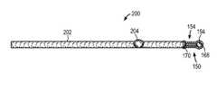
- FIGS. 2A-2Billustrate a contraceptive device in accordance with one embodiment of the invention
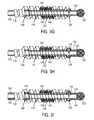
- FIGS. 3 , 3 A- 3 Iillustrate a contraceptive device in accordance with one embodiment of the invention
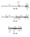
- FIG. 4Aillustrates a contraceptive device in an expanded position in accordance with one embodiment of the invention
- FIGS. 4B-4Eillustrate a contraceptive device and delivery system in accordance with one embodiment of the invention
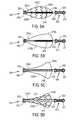
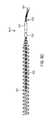
- FIGS. 5A-5Eillustrate a contraceptive device in accordance with one embodiment of the invention
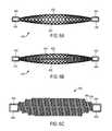
- FIGS. 6A-6Cillustrate a contraceptive device in accordance with one embodiment of the invention.
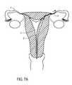
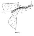
- FIGS. 7A-7Gillustrate delivery of a contraceptive device in accordance with one embodiment of the invention.
- FIG. 8Ais a perspective view of a contraceptive device being assembled
- FIG. 8Bis a perspective view of the contraceptive device of FIG. 8A after a hydrogel cylinder has been added to the device
- FIG. 8Cis a cross-sectional view of the device of FIG. 8B , wherein the cross-section is taken at line 8 C- 8 C in FIG. 8B .
- FIG. 8Dis a side view of a contraceptive device which is similar to the contraceptive device in FIG. 8B .
- the contraceptive devicemay include an expandable implant.
- the implantincludes hydrogel to provide substantially immediate sterilization, and tissue in-growth promoting agent or fibers to provide permanent sterilization.
- the hydrogelcan provide immediate sterilization by swelling in a physiological environment once the device with hydrogel is deployed, and the tissue in-growth promoting agent (such as polyester fibers) promotes in-growth of tissue to permanently occlude the fallopian tube into which the device is implanted.
- the implantmay include copper or cupric ions to provide substantially immediate sterilization.
- the implantmay also include hydrogel to improve trackability (to provide ease of movement) of the implant through an ovarian pathway.
- the hydrogelcan be formulated to be radiopaque (for X-ray visualization) or be visible under ultrasound imaging or MRI imaging.
- Hydrogelsmay be formed from covalently or non-covalently crosslinked materials, and may be non-degradable (“biostable”) in a physiological environment or broken down (biodegradable) by natural processes within the body, referred to as biodegradable or bioabsorbable.
- biodegradablenon-degradable
- bioabsorbableThe breakdown process may be due to one of many factors in the physiological environment, such as enzymatic activity, heat, hydrolysis, or others, including a combination of these factors.
- Hydrogels that are crosslinkedmay be crosslinked by any of a variety of linkages, which may be reversible or irreversible. Reversible linkages may be due to ionic interaction, hydrogen or dipole type interactions or the presence of covalent bonds.
- Covalent linkages for absorbable or degradable hydrogelsmay be chosen from any of a variety of linkages that are known to be unstable in an animal physiological environment due to the presence of bonds that break either by hydrolysis (e.g., as found in synthetic absorbable sutures), enzymatically degraded (e.g., as found in collagen or glycosamino glycans or carbohydrates), or those that are thermally labile (e.g., azo or peroxy linkages).
- hydrogel materials appropriate for use in the present inventionshould be physiologically acceptable and should be swollen in the presence of water. These characteristics allow the hydrogels to be introduced into the body in a “substantially deswollen” state and over a period of time hydrate to fill a void, a defect in tissue, or create a hydrogel-filled void within a tissue or organ by mechanically exerting a gentle force during expansion.
- the hydrogelmay be preformed or formed in situ.
- the hydrogelcan, in one embodiment, be made to be radiopaque by incorporating heavy metals or heavy metal compounds, such as barium sulfate, platinum, tungsten, gold, or iridium-based contrast material, into the hydrogel.
- the hydrogelcan, in one embodiment, be made to be radiopaque by incorporating air/gas bubbles into the hydrogel; in some cases, the hydrogel will be inherently visible in ultrasound imaging modalities.
- “Substantially deswollen”is defined as the state of a hydrogel wherein an increase in volume of the hydrogel of the article or device formed by such hydrogel is expected on introduction into the physiological environment.
- the hydrogelmay be in a dry state, or less than equilibrium hydrated state, or may be partially swollen with a pharmaceutically acceptable fluid that is easily dispersed or is soluble in the physiological environment.
- the expansion processalso may cause the implanted material to become firmly lodged within a hole, an incision, a puncture, or any defect in tissue which may be congenital, diseased, or iatrogenic in origin, occlude a tubular or hollow organ, or support or augment tissue or organs for some therapeutic purpose.
- Hydrogels useful in practicing the present inventionmay be formed from natural, synthetic, or biosynthetic polymers.
- Natural polymersmay include glycosminoglycans, polysaccharides, proteins etc.
- glycosaminoglycanis intended to encompass complex polysaccharides which are not biologically active (i.e., not compounds such as ligands or proteins) and have repeating units of either the same saccharide subunit or two different saccharide subunits.
- glycosaminoglycansinclude dermatan sulfate, hyaluronic acid, the chondroitin sulfates, chitin, heparin, keratan sulfate, keratosulfate, and derivatives thereof.
- the glycosaminoglycansare extracted from a natural source and purified and derivatized. However, they also may be synthetically produced or synthesized by modified microorganisms such as bacteria. These materials may be modified synthetically from a naturally soluble state to a partially soluble or water swellable or hydrogel state. This modification may be accomplished by various well-known techniques, such as by conjugation or replacement of ionizable or hydrogen bondable functional groups such as carboxyl and/or hydroxyl or amine groups with other more hydrophobic groups.
- carboxyl groups on hyaluronic acidmay be esterified by alcohols to decrease the solubility of the hyaluronic acid.
- Such processesare used by various manufacturers of hyaluronic acid products (such as Genzyme Corp., Cambridge, Mass.) to create hyaluronic acid based sheets, fibers, and fabrics that form hydrogels.
- Synthetic polymeric hydrogelsgenerally swell or expand to a very high degree, usually exhibiting a 2 to 100-fold volume increase upon hydration from a substantially dry or dehydrated state.
- Synthetic hydrogelsmay be biostable or biodegradable or bioabsorbable.
- Biostable hydrophilic polymeric materials that form hydrogels useful for practicing the present inventioninclude poly(hydroxyalkyl methacrylate), polyelectrolyte complexes), poly(vinylacetate) cross-linked with hydrolysable bonds, and water-swellable N-vinyl lactams.
- hydrophilic hydrogelsknow as CARBOPOL®, a registered trademark of B.F. Goodrich Co., Akron, Ohio, for acidic carboxy polymer (Carbomer resins are high molecular weight, allylpentaerythritol-crosslinked, acrylic acid-based polymers, modified with C10-C30 alkyl acrylates), polyacrylamides marketed under the CYANAMER® name, a registered trademark of Cytec Technology Corp., Wilmington, Del., polyacrylic acid marketed under the GOOD-RITE.® name, a registered trademark of B.F.
- CARBOPOL®a registered trademark of B.F. Goodrich Co., Akron, Ohio
- Carbomer resinsare high molecular weight, allylpentaerythritol-crosslinked, acrylic acid-based polymers, modified with C10-C30 alkyl acrylates
- polyacrylamidesmarketed under the CYANAMER® name, a registered trademark of Cytec Technology Corp., Wilmington
- Hydrogelsalso may be formed to be responsive to changes in environmental factors, such as pH, temperature, ionic strength, charge, etc., by exhibiting a corresponding change in physical size or shape, so-called “smart” gels.
- thermoreversible hydrogelssuch as those formed of amorphous N-substituted acrylamides in water, undergo reversible gelation when heated or cooled about certain temperatures (lower critical solution temperature, LCST).
- Prevailing gel formation mechanismsinclude molecular clustering of amorphous polymers and selective crystallization of mixed phases of crystalline materials.
- Such gelswhich are insoluble under physiological conditions, also advantageously may be used for practicing the present invention.
- a substantially dehydrated hydrogelrehydrates in a physiological environment, such as encountered upon implantation in an animal.
- creating a porous structure within the hydrogel by incorporating a blowing agent during the formation of the hydrogelmay lead to more rapid re-hydration due to the enhanced surface area available for the water front to diffuse into the hydrogel structure.
- a two component mixture of the precursors to a hydrogel forming systemmay be selected such that foaming and polymerization to form the hydrogel are initiated when the two fluid channels are mixed.
- a double barrel syringe assemblymay be provided to mix the fluids, in which each barrel is equipped with a separate plunger to force the material contained therein out through a discharge opening.
- the plungerspreferably are connected to one another at the proximal ends so that a force exerted on the plungers generates equal pressure within each barrel and displaces both plungers an equal distance.
- the hydrogel forming precursors for the foregoing systemmay be selected so that, for example, a free radical polymerization is initiated when two components of a redox initiating system are brought together.
- One of these componentsadditionally may include a foaming agent, e.g., sodium bicarbonate, that when exposed to an acidic environment (e.g., the other component in the syringe may comprise an acidic solution), releases carbon dioxide as a foaming agent.
- a foaming agente.g., sodium bicarbonate
- the effervescent compoundreacts with the water-soluble acid to release gases, the hydrogel structure is polymerizing and crosslinking, thereby causing the formation of a stable foamed gel.
- other techniqueswhich are per se known, may be used to foam the hydrogels.
- the driving force for water to penetrate a dehydrated hydrogelalso may be influenced by making the hydrogel hyperosmotic relative to the surrounding physiological fluids. Incorporation of charged species within hydrogels, for example, is known to greatly enhance the swellability of hydrogels. Thus the presence of carboxyl or sulfonic acid groups along polymeric chains within the hydrogel structure may be used to enhance both degree and rate of hydration.
- the surface to volume ratio of the implanted hydrogelsalso is expected to have an impact on the rate of swelling. For example, crushed dried hydrogel beads are expected to swell faster to the equilibrium water content state than a rod shaped implant of comparable volume.
- in-situ formed hydrogels formed from aqueous solutions of precursor moleculesmay be used.
- the hydrogelsmay be absorbable or biostable.
- the precursor solutionspreferably are selected so that the hydrogels when formed in the physiological environment are below the equilibrium level of hydration.
- the hydrogelswhen formed in-situ, the hydrogels have the ability to hydrate and increase in size. If the hydrogels are formed in confined tissue spaces, the additional swelling is expected to further anchor the hydrogel in place.
- hydrogelsin-situ.
- monomers or macromers of hydrogel forming compositionsmay be further polymerized to form three dimensionally cross-linked hydrogels.
- the crosslinkingmay be covalent, ionic, and or physical in nature.
- Polymerization mechanisms permitting in-situ formation of hydrogelsare per se known, and include, without limitation, free radical, condensation, anionic, or cationic polymerizations.
- the hydrogelsalso may be formed by reactions between nucleophilic and electrophilic functional groups, present on one or more polymeric species, that are added either simultaneously or sequentially.
- the formation of hydrogelsalso may be facilitated using external energy sources, such as in photoactivation, thermal activation and chemical activation techniques.
- Absorbable polymersoften referred to as biodegradable polymers, have been used clinically in sutures and allied surgical augmentation devices to eliminate the need for a second surgical procedure to remove functionally equivalent non-absorbable devices. See, for example, U.S. Pat. No. 3,991,766 to Schmitt et al. and Shalaby, Encyclopedia of Pharmaceutical Technology (Boylan & Swarbrick, Eds.), Vol. 1, Dekker, N.Y., 1988, p. 465. Although these previously known devices were intended for repairing soft tissues, interest in using such transient systems, with or without biologically active components, in dental and orthopedic applications has grown significantly in the past few years.
- hydrogelshave been studied for controlled drug release and membranes for the treatment of post-surgical adhesion.
- Those hydrogelsare based on covalent networks formed by the addition polymerization of acrylic-terminated, water-soluble polymers that have at least one biodegradable spacer group separating the water soluble segments from the crosslinkable segments, so that the polymerized hydrogels degrade in vivo.
- Such hydrogelsare described in U.S. Pat. No. 5,410,016, which is incorporated herein by reference, and may be particularly useful for practicing the present invention.
- Hydrogels for use in the present inventionmay be formed by the polymerization of macromers that form hydrogel compositions that are absorbable in vivo.
- macromersfor example, may be selected from compositions that are biodegradable, polymerizable, and substantially water soluble macromers comprising at least one water soluble region, at least one degradable region, and statistically more than 1 polymerizable region on average per macromer chain, wherein the polymerizable regions are separated from each other by at least one degradable region.
- Hydrogelsthat have some mechanical integrity and that cannot be “extruded” from the implantation site by forces applied by natural movement of surrounding tissues are preferred for this invention.
- hydrogels suitable for use in the present inventionpreferably are physically or chemically crosslinked, so that they possess some level of mechanical integrity even when fully hydrated.
- the mechanical integrity of the hydrogelsmay be characterized by the tensile modulus at breaking for the particular hydrogel. Hydrogels having a tensile strength in excess of 10 KPa are preferred, and hydrogels having a tensile strength greater than 50 KPa are more preferred.
- a hydrogel for use with any of the fallopian tube implants described hereincan be created from a mixture of a solution containing sodium metaborate (or “Borax”) and a solution containing polyvinyl alcohol (PVA).
- a hydrogelwhich can be applied as a liquid (which is gelling), onto a fallopian tube implant (or a set of implants).
- the liquiddries onto the implant to create the dried (deswollen) hydrogel which will swell after being introduced into a fallopian tube.
- the swollen hydrogelcan fully and/or functionally occlude the fallopian tube at least until the tissue ingrowth promoting agent has caused sufficient tissue ingrowth into the fallopian tube to occlude the tube.
- the mixture of the two solutionscan be applied repeatedly onto the implant to build up, over time, a hydrogel component on the implant; for example, a few drops of the mixture can be applied to an implant and allowed to dry (e.g. with the aid of heated air, such as air from a conventional hair dryer, etc.) and then further drops of the mixture are applied to the dried hydrogel on the implant to build up the structure of the hydrogel on the implant.
- This mixturemay be created from a variety of different formulations such as the following different formulations, shown in the following table.
- Formulation First Solution Second Solution Mixture 14 gm of borax in 100 ml 4 gm of PVA in 200 ml of 7 ml of first solution and 100 ml of water water of second solution 2 4 gm of borax in 100 ml 1 gm of PVA in 100 ml 1.75 ml of first solution of water of water and 7.5 ml of second solution 3 4 gm of borax in 100 ml 1 gm of PVA in 100 ml 1 ml of first solution and 9 ml of water of water of second solution 4 4 gm of borax in 100 ml 1.2 gm of PVA in 100 ml 1.5 ml of first solution and of water of water 9 ml of second solution 5 4 gm of borax in 100 ml 4 gm of PVA in 100 ml 4 ml of first solution and of water of water 50 ml of second solution, then diluted with 60-80 ml of water 6 4 gm of borax in 100
- a procedure for creating the mixture of formulation “1”will now be described.
- Set stirrer speedto at least 300 rpm; this speed should be increased as the ingredients are added to their beakers.
- hydrogelcan be formed from a molded mixture of Polyethylene Oxide (PEO) and Triallyl Isocyanurate (TI). This mixture is molded in a mold into which an implant (e.g. any one of the implants shown or described herein) is placed along with both the PEO and the TI. The mold forms, through a high temperature and high pressure process, a hydrogel on the implant.
- PEOPolyethylene Oxide
- TITriallyl Isocyanurate
- the PEO and ITare mixed together, as powders, in a conventional tumble mixer and then added, as a mixed powder to the mold (and the implant is also placed into the mold),
- 100 gm of PEOis mixed with about 0.25 to 0.8 gm of TI and this mixture is mixed in a tumble mixer and then molded, in a mold with an implant in the mold, at a temperature and pressure sufficient to melt both powders and to form a hydrogel bonded to the implant in the mold.
- a hydrogel from Hydromer Incorporated of Branchburg, N.J.may be used as a hydrogel applied to any of the fallopian tube implants described herein.
- the fallopian tubes Fare accessed via the tubal ostiums O.
- the fallopian tubes Fgenerally include three segments between the ostium O and the fimbria FIM. Beginning adjacent the uterus U, the intramural segment INT of the fallopian tubes F are surrounded by the muscular uterine tissues. Beginning at the uterotubal junction UTJ, the fallopian tubes F extend beyond the uterine tissues and within the peritoneal cavity along an isthmic segment ISC, and then along an ampullary segment AMP.
- FIGS. 2A , 2 B and FIG. 3illustrate an exemplary expandable implant.
- FIG. 2Aillustrates an implant formed entirely of a polymer or metallic material
- FIG. 2Billustrates the implant formed partially of a polymer material and partially of a metallic material.
- the expandable implantmay be formed from metal such as stainless steel or a superelastic or shape memory material such as a nickel titanium (NiTi) alloy such as nitinol, or platinum, or tantalum, or gold, or rigid or semi-rigid biocompatible plastics.
- the expandable implantmay be formed at least in part from a superelastic material providing a controlled force on the body lumen such as a portion of the fallopian tube during expansion of the implant.
- the implantmay self-expand radially from a first diameter to a second diameter which is larger than the first diameter.
- the implantmay be delivered by a delivery system (e.g.
- a delivery catheterwhich constrains the implant to the size of the first diameter and after the implant is deployed, it may expand to the second diameter which at least slightly exceeds the diameter of a lumen of the fallopian tube.
- the material or materials of the implantmay be superelastic so that the implant can expand in a manner that causes it to resiliently apply an anchoring force against the wall of the fallopian tube, thereby resisting against being expelled by the fallopian tube.
- the expandable implant 100has a proximal end 112 and a distal end 114 .
- the expandable implant 100also includes an inner member 116 and an outer coil 118 .
- the inner member 116includes a tip 120 which may be atraumatic and which is designed to be arranged at a distal end of the implant 100 .
- the tip 120includes a ball 122 at the distal end of the implant 100 .
- the implant 100includes a distal attachment 126 at its distal end which couples the inner member 116 , outer coil 118 and tip 120 .
- the implant 100also includes an end piece 130 which is attached to a proximal end of the outer coil.
- the implant 100also includes a proximal attachment 128 that releasably couples the outer coil 118 with the inner member 116 through the end piece 130 .
- the attachments 126 , 128may be formed by soldering or molding operations in one or more dies.
- the illustrated inner memberincludes optional teeth 132 ; these teeth are designed to, in one embodiment, engage a meshlike material 140 such as polyester fibers or other fibers or furs which are designed to promote a tissue ingrowth into and around the implant 100 and which are one embodiment of a tissue ingrowth promoting agent, as shown in FIG. 3 .
- the tissue ingrowth promoting agent 140is disposed between the outer coil 118 and the inner member 116 .
- the surface of the implantmay be designed to facilitate epithelial growth; one way of doing this is to provide the implant with an open or latticelike framework to promote and support epithelial growth into as well as around the implant to ensure secure attachment to an embodiment within the wall of the body lumen.
- the implantmay include a tissue ingrowth promoting agent such as a polyester fiber (e.g. polyethylene terephthalate) or other materials known to facilitate fibrotic or epithelial growth.
- the surface of the implantmay also be modified or treated or include such a tissue ingrowth promoting material.
- the surface modificationmay include plasma deposition or laser drilling or photochemical etching or sintering and the like. Further, increasing the surface area of the implant by such surface modification techniques (e.g.
- the implantmay be coated or seeded to spur epithelialization.
- the implantcan be coated with a polymer having impregnated therein a drug, enzyme or protein for inducing or promoting epithelial tissue growth. Any of these various techniques for including a tissue ingrowth promoting agent may be used with the various other implants shown or described herein.
- hydrogel 134is also provided on the implant.
- the hydrogel 134is provided on the distal ball 122 , tip 120 , distal attachment 126 , proximal attachment 128 and end piece 130 .
- the hydrogelis provided on the implant by coating each of the distal ball 122 , tip 120 , distal attachment 126 , proximal attachment 128 and end piece 130 with hydrogel (which after the coating preferably obtains a de-swollen state).
- the hydrogelneed not be provided on each of the distal ball 122 , tip 120 , distal attachment 126 , proximal attachment 128 and end piece 130 .
- the hydrogel 134is applied to the distal ball 122 , tip 120 and the distal attachment 126 but not to the rest of the implant; as shown in FIG. 3A , the hydrogel 134 is a coating provided on only the end piece 130 .
- the hydrogel 134is a coating provided only on the proximal attachment 128 .
- the hydrogel 134is a coating provided on both the proximal attachment 128 and the end piece 130 .
- a hydrogel coating 134is provided on the distal attachment 126 .
- a hydrogel coating 134is provided on the distal attachment 126 and the distal ball 122 .
- a hydrogel coating 134is provided only on the distal ball 122 . It will be appreciated that other combinations of coatings may be provided; the above description was merely exemplary.
- the hydrogelis provided as a coating.
- a portion of the implant 100may be made of hydrogel.
- the distal ball 122is made entirely of hydrogel.
- the distal ball 122is made of hydrogel and the distal tip 120 and distal attachment 126 are both coated with hydrogel 134 .
- the distal ball 122is made of hydrogel, and the distal tip 120 , distal attachment 126 , proximal attachment 128 and end piece 130 are coated with hydrogel 134 .
- the distal ball 122may be formed from hydrogel by, for example, molding the hydrogel around the tip 120 .
- a hydrogel plugmay be attached (e.g., adhered, affixed) to the tip 120 .
- FIG. 4Aillustrates another implant 150 that can be used in accordance with one embodiment of the invention.
- the implant 150has a proximal end 152 and a distal end 154 .
- the implant 150includes an inner coil 162 , an outer coil 164 and a flexible tip 166 having a distal ball 168 .
- the implant 150also includes a distal attachment 170 connecting the inner coil 162 , outer coil 164 and flexible tip 166 .
- An end piece 172is provided at the proximal end 152 of the implant 150 .
- the end piece 172releasably couples the implant 150 to a release catheter (e.g. a delivery wire) and attaches the inner coil 162 and outer coil 164 at their proximal ends until the implant is to be expanded.
- the flexible tip 166may have a slight (e.g. 15 degree), preformed bend.
- the implant 150may also include a tissue ingrowth promoting agent 190 , which is secured to the inner coil 162 or to the outer coil 164 .
- the tissue ingrowth promoting agentmay be a polyester fiber or other types of agents designed to cause tissue ingrowth to functionally occlude the fallopian tube.
- the contraceptive device 150resembles the Essure device from Conceptus, Inc. of Mountain View, Calif., in that there is an outer coil which may be formed from a superelastic or resilient member and an inner coil which is coupled to the outer coil.
- the outer coilis designed to radially expand (e.g. through self expansion after it is deployed) to engage the walls of a portion of the fallopian tube to thereby engage those walls and hold the device within the fallopian tube.
- Hydrogel 194may also be provided on the implant 150 .
- the hydrogel 194may be a coating or a component of the implant 150 and may be formed as described above.
- each of the distal ball 168 , flexible tip 166 , distal attachment 170 and end piece 172are coated in hydrogel 194 .
- the implant 150may include copper and/or cupric ions.
- the implant 150(or implant 100 ) is delivered to a fallopian system using a delivery system, such as the delivery system 200 shown in FIGS. 4B-4E .
- the delivery system 200includes a delivery catheter 202 and a marker 204 disposed on the delivery catheter 202 .
- the marker 204may be one or more of the various types of conventional markers such as an optically visible marker (e.g. a marker which is colored to distinguish from its surroundings) which is visible during a hysteroscopy by visible light and a camera or a radiopaque marker or an ultrasound marker (which is visible in an ultrasound image) or other known markers.
- an optically visible markere.g. a marker which is colored to distinguish from its surroundings
- an ultrasound markerwhich is visible in an ultrasound image
- FIG. 4Bthe distal portion 154 of the contraceptive device 150 is shown.
- FIG. 4Cshows the implant 150 after the delivery catheter 202 has been retracted (or alternatively, the contraceptive device has been pushed relative to the delivery catheter) such that the implant 100 is fully viewable.
- the end piece 172 of the implant 150is adjacent to and abuts a release catheter 210 .
- the release catheter 210may include a pin or other interface designed to mate with a receptor or other interface on the end piece 172 to thereby releasably couple the contraceptive device 150 to the release catheter 210 .
- the two interface elements on the release catheter 210 and the end piece 172are coupled through an interference fit or a friction fit or a screw fit.
- the contraceptive device and the release cathetercan, in one embodiment, be released by retracting the release catheter.
- the two interface elements on the release catheter 210 and the end piece 172may resemble a screw and a nut which more securely secures the contraceptive device and release catheter to each other.
- the contraceptive device and release cathetercan be released by unscrewing the contraceptive device from the release catheter after the contraceptive device has been implanted.
- the expanded contraceptive deviceresembles the implant as shown in FIG. 4A .
- FIG. 4Dshows an alternative embodiment of the delivery catheter 202 .
- the sheath of the delivery catheter 202is substantially coated in a hydrophilic coating (not shown) to minimize friction, while the distal end 224 of the delivery catheter 202 is coated with a hydrophobic coating 226 to prevent the hydrogel, on the implant, from swelling before the implant 150 is delivered to the fallopian tube.
- the distal end of the implant 150may extend, in one embodiment, beyond the distal end of the sheath during delivery (but before release of the implant) and hence the coating can protect the implant, during delivery, from saline even though the implant extends beyond the end of the sheath during delivery. Any suitable material that is compatible for use in medical or therapeutic applications may be used for the hydrophobic coating.
- the hydrophobic coating 226encapsulates the distal end of the delivery catheter and prevents saline from entering the distal end, and hence the coating 226 protects the hydrogel on the implant from the surrounding saline environment until the coating 226 is pierced, dissolved or removed.
- the implante.g., implant 150 or implant 100
- implant 150 or implant 100is surrounded by and encapsulated by the sheath of the delivery catheter and is therefore not exposed to a physiological environment of a fallopian tube until the hydrophobic coating 226 is pierced, dissolved or removed.
- the hydrophobic coating 226may be rapidly bioabsorbable or biodegradable within a physiological environment, and hence it will naturally dissolve in the presence of a physiological environment.
- the coating 226can be pierced by retracting the sheath of the delivery catheter (while the implant within the sheath is held stationary and pushes through the coating 226 ) or by pushing the implant through the sheath (or by a combination of retracting proximally the sheath while pushing distally the implant).
- the coating 226can be a hydrophilic coating which can be pierced or dissolved or removed; for example, it can be a hydrophilic coating that is rapidly biodegradable or bioabsorbable in a physiological environment within a fallopian tube.
- a coating, such coating 226can encapsulate the entire implant at both proximal and distal ends of the implant d no sheath is needed; this coating can be biodegradable or bioabsorbable and allow for the delivery catheter to deliver the implant without a sheath.
- FIG. 4Eshows another embodiment of the delivery catheter 202 in which a hydrophobic membrane 230 is provided over the distal end 224 of the delivery catheter 202 .
- the hydrophobic membrane 230similarly prevents the hydrogel from swelling before the implant 150 is delivered to the fallopian tube.
- the membrane 230may be pierceable, dissolvable or removable such that the implant 150 can be delivered through the distal end of the delivery catheter 202 .
- FIGS. 5A-5Eshow alternative embodiments of implants, which may include hydrogel as described above.
- the implant 250 of FIG. 5Aincludes a tip 251 near the distal portion 253 and also includes an attachment 252 which couples the distal end of top and bottom members 255 A and 255 B to the implant 250 .
- Hydrogel 350is applied, as a coating in one embodiment, to the distal portion 253 and to the end piece 256 .
- the proximal ends of these membersare coupled to end piece 256 which is also coupled to an inner frame 254 A which is coupled to the core 254 .
- An inner mesh 255 Cis coupled to and extends from each of the members to the inner core 254 and to the inner frame 254 A as shown in FIG. 5A .
- the inner meshmay be formed from the same material as the top and bottom members or may be formed from a tissue ingrowth promoting agent.
- FIG. 5Bshows an implant 270 which includes a tip 271 at a distal portion 273 and an attachment 272 which attaches the top and bottom members 275 A and 275 B to the core 274 .
- the core 274is attached to an inner frame 274 A which is in turn attached to an end piece 276 .
- the proximal ends of the top and bottom members 275 A and 275 Bare attached to the end piece 276 as shown in FIG. 5B .
- the top and bottom members 275 A and 275 Bmay be formed from a material such as a superelastic or shape memory material which radially expands from a contracted state to an enlarged state similar. This is also true of the top member 255 A and the bottom member 255 B shown in FIG. 5A , as well as the other top and bottom members shown in FIGS. 5C , 5 D and 5 E.
- FIG. 5Cshows an implant 290 which includes a tip 291 near a distal portion 293 which in turn is coupled to an attachment 292 which attaches the top and bottom members 295 A and 295 B to the core 294 as shown in FIG. 5C .
- An inner frame 294 A which is coupled to the core 294is coupled at its proximal end to an end piece 296 which in turn is coupled to the proximal ends of the top and bottom members 295 A and 295 B.
- FIG. 5Dshows an implant 310 which includes a tip 311 near a distal portion 313 .
- An attachment 312is coupled to the distal portion 313 and is also coupled to the distal ends of the top and bottom members 315 A and 315 B.
- a core 314is also coupled to the attachment 312
- an inner frame 314 Ais coupled to the core 314 .
- the proximal portion of the inner frame 314 Ais coupled to an end piece 316 .
- the end piece 316is coupled to a proximal end of each of the top and bottom members 315 A and 315 B.
- An inner mesh 317which is similar to the mesh 255 C of FIG. 5A , is coupled between the top and bottom members and the core 314 and the inner frame 314 A.
- the inner frame 314 Amay be the same component as the distal portion 313 .
- FIG. 5Eshows an alternative embodiment of another implant in which the top and bottom members are secured only to the attachment 332 and not to the end piece 334 A which is at the proximal end of the core 334 .
- the implant 330 of FIG. 5Ealso includes a tip 331 which is coupled to a distal portion 333 which is in turn coupled to an attachment 332 .
- the core 334may, in an alternative embodiment, be the same component as the distal portion 333 .
- the distal ends of the top and bottom members 335 A and 335 Bare coupled to the attachment 332 .
- the designs shown in FIGS. 5A-5Emay be formed from multiple pieces which are brought together or may be formed as one piece.
- Hydrogel 350may also be provided on any one of the implants 250 , 270 , 290 , 310 or 330 .
- the hydrogel 350may be a coating or a component of implants 250 , 270 , 290 , 310 or 330 may be formed of hydrogel, as described above. It will be appreciated that variations to the coatings of the implants 250 , 270 , 290 , 310 or 330 may be made as described above with reference to FIGS. 3-3I .
- any one of the implants 250 , 270 , 290 , 310 or 330may include copper and/or cupric ions.
- any one of the implants 250 , 270 , 290 , 310 , or 330may include a tissue ingrowth promoting agent as described herein.
- FIG. 6Ashows a top view of one particular exemplary implant 400 which resembles a braided stent that has a frame 402 which surrounds an inner portion 408 which may be hollow or may be filled with a mesh or other tissue ingrowth promoting agents.
- the ends of the frame 402are capped by ends 404 and 406 as shown in FIG. 6A .
- the ends of the frame 402are opened and are not capped.
- FIG. 6Bshows a top view of another exemplary implant 420 which is similar to implant 400 except that implant 420 includes an inner member (e.g. a coil 434 ) which is surrounded by the braided frame 422 and which is attached to ends 424 and 426 .
- the coil 434is disposed within the open, hollow inner portion 428 which is also surrounded by the braided frame 422 .
- the open, hollow inner portion 428may include a tissue ingrowth promoting agent such as a polyester fiber or fibers (e.g. polyethylene terephthalate) or other materials known to facilitate fibrotic or epithelial growth.
- FIG. 6Cshows a top view of another exemplary implant 450 which includes two coils 452 and 454 which are each attached to end 458 on one side (e.g. a distal end) of implant 450 and which are each attached to end 456 on the other side (e.g. a proximal end) of implant 450 .
- An open, hollow inner portionis contained within the space defined by the two coils 452 and 454 .
- This open, hollow inner portionmay optionally include a tissue ingrowth promoting agent (e.g. polyester fibers) and it may further optionally include an inner member (e.g. a coil, not shown, which resembles coil 434 ) which is surrounded by the two coils 452 and 454 .
- tissue ingrowth promoting agente.g. polyester fibers
- the implant 450may be designed so that a compressive force on one end of the implant 450 causes the other end to expand. This will tend to provide an anchoring force against the wall of a fallopian tube at least at one point of the implant 450 .
- the tissue ingrowth promoting agentsmay be placed within the implant or on the exterior of the implant or both within and on the exterior of the implant. These agents may extend longitudinally and/or traversely to the implants.
- Hydrogel 460may also be provided on any one of the implants 400 , 420 or 450 .
- the hydrogel 460may be a coating or a component of any one of the implants 400 , 420 or 450 may be formed of hydrogel, as described above. It will be appreciated that variations to the coatings may be made as described above with reference to FIGS. 3-3I .
- any one of the implants 400 , 420 or 450may include copper and/or cupric ions.
- any one of the implants 400 , 420 or 450may include a tissue ingrowth agent as described herein.
- FIGS. 7A-Gillustrate a method of delivering the contraceptive device to a fallopian tube and facilitating substantially immediate and permanent sterilization.
- FIGS. 7A-7Gillustrate delivery of implant 150 ; however, other implants described herein may be delivered in a similar manner. Variations as known to those of skill in the art may need to be made for some of the implants described above.
- a delivery system Ssuch as delivery system 200 is introduced transcervically through uterus U, generally under optical direction.
- the physiciandirects the distal end of the delivery system toward the ostium O of the fallopian tube F.
- the uterus Umay be irrigated and/or distended. Once the ostium O is located and the delivery system S is oriented toward the ostium, the delivery system S is advanced distally into the ostium.
- the distal portion of the contraceptive deviceacts as a guidewire, while the remainder of the contraceptive device remains covered by the sheath 202 , as shown in FIG. 7B .
- the distal ball tip 168 of the distal portion of the deviceaids tracking and navigation through the fallopian tube F, while the primary coil structure flexes laterally to track the tortuous bends often found within the fallopian tube.
- a core wireextends into the distal portion to enhance column strength of the distal portion beyond sheath, but does not extend to the ball tip. Hence, the stiffness of distal portion increases proximally, further enhancing the distal portion's ability to track the lumen.
- the contraceptive deviceincludes hydrogel at the distal portion of the contraceptive device (e.g., distal ball)
- the hydrogelwill swell during delivery (if it is exposed).
- the expanded or expanding hydrogel distal ballcan improve trackability of the contraceptive device through the bends of the fallopian tube, particularly in those embodiments in which the hydrogel is formulated to improve trackability.
- the contraceptive devicewill be entirely within the delivery catheter 202 during delivery and positioning.
- the sheathincludes a visual marker which can be seen from the scope of an hysteroscope.
- the markeris preferably positioned partially within the ostium O and partially within the uterus U, thereby indicating that the contraceptive device is disposed at the target position, as the sheath, core shaft, and contraceptive device are releasably locked together during advancement and positioning.
- the markermay comprise a bumper, a structure which extends radially from the sheath to provide a tactile positioning indication.
- the positioned contraceptive deviceis deployed, in one embodiment, by first withdrawing the sheath of the delivery catheter 202 from over the expandable structure 150 , as shown in FIG. 7C .
- the outer coil 164 of the contraceptive device 150is separated from the release catheter 210 , allowing the outer coil 164 to expand, as shown in FIG. 7D .
- the outer coil 164resiliently expands and affixes the contraceptive device 150 in place.
- the hydrogel 194has, at this point, begun to swell and will at least temporarily block the fallopian tube.
- the contraceptive device 150is separated from the remaining components of delivery system, as shown in FIG. 7E .
- the hydrogelmay expand to fill in areas of the fallopian tube and/or ostium to block the ovarian pathway (if hydrogel is present on the proximal end of the device as in the case of the example shown in FIG. 7F ).
- tissuehas grown within the implant because of the tissue reaction caused by the tissue ingrowth fibers.
- the hydrogelis no longer present; in such an embodiment, the hydrogel is biodegradable. It will be appreciated that the hydrogel need not be biodegradable (hydrogel and tissue ingrowth together provide sterilization).
- FIGS. 8A , 8 B and 8 Cshow another example of an embodiment of a contraceptive device according to one aspect of the invention.
- the contraceptive device 801 shown in FIG. 8Acan be formed from one or more metals or organic polymers and can include Dacron or polyester fibers to act as a tissue ingrowth promoting agent to cause tissue to grow into the device after it has been implanted into a fallopian tube.
- the Dacron or polyester fibers (or other tissue ingrowth promoting agents)can be attached to one or more components (e.g. the outer coil 803 ) of the device.
- the outer coil 803can be configured to be resilient and self-expanding from a deployed configuration; the outer coil 803 can be restrained within a delivery catheter or sheath and once deployed can radially expand to resiliently engage the walls of a fallopian tube.
- a delivery shaft or wire in the delivery catheter(not shown) can be removably attached to a proximal end of the inner coil 805 ; a connection between the proximal end of the inner coil 805 and a delivery shaft or wire can be any one of known or conventional connections that allow the delivery shaft or wire to be removably coupled to the contraceptive device 801 .
- the inner coil 805 and the outer coil 803can be connected together by a connection mechanism 807 which can be a solder joint.
- a preformed or cast hollow cylinder of hydrogelsuch as the hydrogel cylinder 809
- a preformed or cast hollow cylinder of hydrogelcan be applied onto the distal end of the inner coil 805 prior to applying the distal ball 813 .
- the application of the cylinder 809 onto the distal end of the inner coil 805 in this manneris represented by arrow 811 which shows how the cylinder 809 can be slid onto the distal end of the inner coil 805 .
- the hydrogel 809can be slid onto the coil 805 when the hydrogel 809 is in a dehydrated state so that it is not swollen.
- the hydrogel 809can be either a non-biodegradable hydrogel or a biodegradable hydrogel.
- the hydrogel 809is designed to swell to an enlarged configuration, as described herein, when placed within a fallopian tube.
- a gluecan be applied between the cylinder 809 and the inner coil 805 either before or after sliding the cylinder 809 onto the distal end of the inner coil 805 .
- the inner coil 805can be stretched before applying the cylinder 809 .
- the gluecan be applied to either or both of the cylinder 809 and the inner coil 805 .
- the gluecan be cyanoacrylate such as Loctite 4541 or 431 or 3211 or a mixture of cyanoacrylate glues from Henkel Corporation.
- the gluecan be cured with or without UV (ultraviolet) light.
- the gluecan be selected to enhance the structural integrity or strength of the hydrogel after the glue has been cured.
- the glue, before curingcan be one color and after curing change to another color, and this can assist in determining when the curing process is completed.
- the hydrogel 809can be applied onto the coil 805 without glue in some embodiments.
- distal ball 813can be attached to the coil 805 (for example, by soldering or by gluing the ball 813 onto the distal end of the coil 805 ).
- the ball 813can be attached to the coil 805 before the hydrogel 809 is applied onto the coil (e.g. if the inner diameter of the hydrogel 809 is larger than the outer diameter of the distal ball 813 ).
- FIG. 8Cshows a cross-sectional view of the contraceptive device 801 A (shown in FIG. 8B ) taken along the line 8 C- 8 C also shown in FIG. 8B .
- This cross-sectional viewshows that the hydrogel 809 concentrically surrounds the inner coil 805 .
- the hydrogel 809can be formed or cast to fit snugly or loosely around the inner coil 805 , and a layer of glue may exist at the interface or gap between the inner coil 805 and the inner diameter of the hydrogel 809 .
- FIG. 8Dshows, in a side view, an embodiment of a contraceptive device in which the distal end has a preformed bend 829 .
- the preformed bend 829is designed to assist in the introduction of the device into the ostium of a fallopian tube.
- the angle of the bendcan be from 5° to 20° relative to the remainder of the device 801 B.
- the contraceptive device 801 Ecan include an inner coil 823 and an outer coil 821 which can be similar to inner coil 805 and outer coil 803 of the contraceptive device 801 .
- a connection 825connects the inner coil 823 to the outer coil 821 , and this connection 825 can be similar to the connection mechanism 807 .
- the device 801 Balso includes hydrogel 827 attached between the distal ball 831 and the connection mechanism 807 .
- the distal ball 831 and the distal ball 813can both be atraumatic balls designed to act as a distal guide for self-insertion and introduction of the devices into a fallopian tube.
Landscapes
- Health & Medical Sciences (AREA)
- Life Sciences & Earth Sciences (AREA)
- Surgery (AREA)
- Engineering & Computer Science (AREA)
- Veterinary Medicine (AREA)
- Biomedical Technology (AREA)
- Heart & Thoracic Surgery (AREA)
- Animal Behavior & Ethology (AREA)
- General Health & Medical Sciences (AREA)
- Public Health (AREA)
- Reproductive Health (AREA)
- Nuclear Medicine, Radiotherapy & Molecular Imaging (AREA)
- Medical Informatics (AREA)
- Vascular Medicine (AREA)
- Molecular Biology (AREA)
- Biophysics (AREA)
- Physics & Mathematics (AREA)
- Pathology (AREA)
- Radiology & Medical Imaging (AREA)
- Optics & Photonics (AREA)
- High Energy & Nuclear Physics (AREA)
- Pulmonology (AREA)
- Anesthesiology (AREA)
- Hematology (AREA)
- Gynecology & Obstetrics (AREA)
- Materials For Medical Uses (AREA)
- Prostheses (AREA)
- Orthopedics, Nursing, And Contraception (AREA)
- Medicinal Preparation (AREA)
Abstract
Description
| Formulation | First Solution | Mixture | ||
| 1 | 4 gm of borax in 100 ml | 4 gm of PVA in 200 ml of | 7 ml of first solution and 100 ml | |
| of water | water | of second solution | ||
| 2 | 4 gm of borax in 100 | 1 gm of PVA in 100 ml | 1.75 ml of first solution | |
| of water | of water | and 7.5 ml of second | ||
| solution | ||||
| 3 | 4 gm of borax in 100 | 1 gm of PVA in 100 | 1 ml of first solution and 9 ml | |
| of water | of water | of second solution | ||
| 4 | 4 gm of borax in 100 ml | 1.2 gm of PVA in 100 ml | 1.5 ml of first solution and | |
| of water | of water | 9 ml of second solution | ||
| 5 | 4 gm of borax in 100 ml | 4 gm of PVA in 100 ml | 4 ml of first solution and | |
| of water | of water | 50 ml of second solution, | ||
| then diluted with 60-80 ml | ||||
| of water | ||||
| 6 | 4 gm of borax in 100 ml | 1.3 gm of PVA in 100 ml | 1.5 ml of first solution and | |
| of water | of water | 25 ml of second solution | ||
Claims (49)
Priority Applications (15)
| Application Number | Priority Date | Filing Date | Title |
|---|---|---|---|
| US12/605,304US8434489B2 (en) | 2009-10-23 | 2009-10-23 | Contraceptive devices and methods |
| PCT/US2010/049188WO2011049694A1 (en) | 2009-10-23 | 2010-09-16 | Contraceptive devices |
| AU2010308446AAU2010308446B2 (en) | 2009-10-23 | 2010-09-16 | Contraceptive devices |
| SI201031370ASI2490632T1 (en) | 2009-10-23 | 2010-09-16 | Contraceptive devices |
| DK10757691.0TDK2490632T3 (en) | 2009-10-23 | 2010-09-16 | PREGNANCY DEVICES |
| ES10757691.0TES2613699T3 (en) | 2009-10-23 | 2010-09-16 | Contraceptive devices |
| CA2777190ACA2777190C (en) | 2009-10-23 | 2010-09-16 | Contraceptive devices and methods |
| BR112012009039ABR112012009039A2 (en) | 2009-10-23 | 2010-09-16 | contraceptive methods and devices |
| MX2012004543AMX2012004543A (en) | 2009-10-23 | 2010-09-16 | Contraceptive devices. |
| PT107576910TPT2490632T (en) | 2009-10-23 | 2010-09-16 | Contraceptive devices |
| KR1020127013227AKR101739159B1 (en) | 2009-10-23 | 2010-09-16 | Contraceptive devices |
| EP10757691.0AEP2490632B8 (en) | 2009-10-23 | 2010-09-16 | Contraceptive devices |
| CN201080048159.0ACN102665619B (en) | 2009-10-23 | 2010-09-16 | Contraceptive devices |
| US13/859,629US9421121B2 (en) | 2009-10-23 | 2013-04-09 | Contraceptive devices and methods |
| US15/243,742US20170027740A1 (en) | 2009-10-23 | 2016-08-22 | Contraceptive devices and methods |
Applications Claiming Priority (1)
| Application Number | Priority Date | Filing Date | Title |
|---|---|---|---|
| US12/605,304US8434489B2 (en) | 2009-10-23 | 2009-10-23 | Contraceptive devices and methods |
Related Child Applications (1)
| Application Number | Title | Priority Date | Filing Date |
|---|---|---|---|
| US13/859,629ContinuationUS9421121B2 (en) | 2009-10-23 | 2013-04-09 | Contraceptive devices and methods |
Publications (2)
| Publication Number | Publication Date |
|---|---|
| US20110094519A1 US20110094519A1 (en) | 2011-04-28 |
| US8434489B2true US8434489B2 (en) | 2013-05-07 |
Family
ID=42938334
Family Applications (3)
| Application Number | Title | Priority Date | Filing Date |
|---|---|---|---|
| US12/605,304Expired - Fee RelatedUS8434489B2 (en) | 2009-10-23 | 2009-10-23 | Contraceptive devices and methods |
| US13/859,629Expired - Fee RelatedUS9421121B2 (en) | 2009-10-23 | 2013-04-09 | Contraceptive devices and methods |
| US15/243,742AbandonedUS20170027740A1 (en) | 2009-10-23 | 2016-08-22 | Contraceptive devices and methods |
Family Applications After (2)
| Application Number | Title | Priority Date | Filing Date |
|---|---|---|---|
| US13/859,629Expired - Fee RelatedUS9421121B2 (en) | 2009-10-23 | 2013-04-09 | Contraceptive devices and methods |
| US15/243,742AbandonedUS20170027740A1 (en) | 2009-10-23 | 2016-08-22 | Contraceptive devices and methods |
Country Status (13)
| Country | Link |
|---|---|
| US (3) | US8434489B2 (en) |
| EP (1) | EP2490632B8 (en) |
| KR (1) | KR101739159B1 (en) |
| CN (1) | CN102665619B (en) |
| AU (1) | AU2010308446B2 (en) |
| BR (1) | BR112012009039A2 (en) |
| CA (1) | CA2777190C (en) |
| DK (1) | DK2490632T3 (en) |
| ES (1) | ES2613699T3 (en) |
| MX (1) | MX2012004543A (en) |
| PT (1) | PT2490632T (en) |
| SI (1) | SI2490632T1 (en) |
| WO (1) | WO2011049694A1 (en) |
Cited By (14)
| Publication number | Priority date | Publication date | Assignee | Title |
|---|---|---|---|---|
| US20130019374A1 (en)* | 2011-01-04 | 2013-01-24 | Schwartz Alan N | Gel-based seals and fixation devices and associated systems and methods |
| WO2015050689A2 (en) | 2013-10-01 | 2015-04-09 | Bayer Essure Inc. | Impact force dampening of spring release |
| US20150114401A1 (en)* | 2012-04-24 | 2015-04-30 | Ruben Van Der Vleuten | Applicator for delivering an occluding compound in a fallopian tube |
| US9339411B2 (en) | 2013-03-11 | 2016-05-17 | Bayer Healthcare Llc | Stabilized handle design |
| US20170027740A1 (en)* | 2009-10-23 | 2017-02-02 | Bayer Healthcare Llc | Contraceptive devices and methods |
| WO2017083753A1 (en) | 2015-11-12 | 2017-05-18 | Herr John C | Compositions and methods for vas-occlusive contraception and reversal thereof |
| US20180242981A1 (en)* | 2014-07-25 | 2018-08-30 | Incumedx, Inc. | Covered embolic coils |
| US10342476B2 (en) | 2012-05-17 | 2019-07-09 | Alan N. Schwartz | Localization of the parathyroid |
| US10751124B2 (en) | 2017-01-05 | 2020-08-25 | Contraline, Inc. | Methods for implanting and reversing stimuli-responsive implants |
| US11045246B1 (en) | 2011-01-04 | 2021-06-29 | Alan N. Schwartz | Apparatus for effecting feedback of vaginal cavity physiology |
| US11253391B2 (en) | 2018-11-13 | 2022-02-22 | Contraline, Inc. | Systems and methods for delivering biomaterials |
| US11337858B2 (en) | 2011-11-21 | 2022-05-24 | Alan N. Schwartz | Ostomy pouching system |
| US11406438B2 (en) | 2011-09-23 | 2022-08-09 | Alan N. Schwartz | Instrument for therapeutically cytotoxically ablating parathyroidal tissue within a parathyroid gland |
| US12383421B2 (en) | 2017-01-05 | 2025-08-12 | Contraline, Inc. | Contraceptive devices |
Families Citing this family (32)
| Publication number | Priority date | Publication date | Assignee | Title |
|---|---|---|---|---|
| US8123693B2 (en) | 2005-06-20 | 2012-02-28 | Conceptus, Inc. | Methods and devices for determining lumen occlusion |
| US7918863B2 (en) | 2005-06-24 | 2011-04-05 | Conceptus, Inc. | Minimally invasive surgical stabilization devices and methods |
| US8585616B2 (en) | 2009-10-09 | 2013-11-19 | Conceptus, Inc. | Methods and apparatus for determining fallopian tube occlusion |
| US9138343B2 (en) | 2011-05-31 | 2015-09-22 | Bayer Healthcare Llc | Tip protector sleeve |
| CN102908223B (en)* | 2011-08-03 | 2015-08-05 | 辽宁爱母医疗科技有限公司 | A kind of support of birth control apparatus |
| US20130046326A1 (en)* | 2011-08-19 | 2013-02-21 | Donald K. Jones | Methods and systems for performing intralumenal procedures |
| KR20140098794A (en)* | 2011-11-23 | 2014-08-08 | 마이크로벤션, 인코포레이티드 | Embolic device with shaped wire |
| US9060773B2 (en)* | 2011-12-16 | 2015-06-23 | Covidien Lp | Occlusive implant delivery devices and associated methods |
| EP2822506A4 (en)* | 2012-03-05 | 2015-10-28 | Univ Pennsylvania | SUPERABSORBING COATED STENTS FOR VASCULAR REDUCTION AND ANCHORAGE OF REPLACEMENT FLAPS |
| RU2014148805A (en)* | 2012-05-03 | 2016-06-20 | Раджив Бхушан | TREATMENT OF INFLAMMATORY CONDITIONS AND IMPROVEMENT OF HYGIENIC CONDITION OF THE ORAL CAVITY BY USING AGENTS CONNECTING METALS AND METHYL SULPHONYLMETHANE AS AN AMPLIFIER OF THEIR VEHICLE |
| KR101439492B1 (en)* | 2012-09-18 | 2014-09-12 | 이말연 | Implant for reversible sterilization operation |
| KR101439479B1 (en)* | 2012-09-18 | 2014-09-12 | 이말연 | Implant for vas deference vasectomy |
| CN102871788B (en)* | 2012-09-28 | 2015-01-21 | 王天奇 | Inflatable lumen plug |
| US20140228821A1 (en) | 2013-02-13 | 2014-08-14 | Conceptus Inc. | Delivery catheter with controlled flexibility |
| US9427352B2 (en)* | 2013-03-15 | 2016-08-30 | Bayer Healthcare Llc | Hydration prevention coating |
| US10660645B2 (en) | 2013-03-15 | 2020-05-26 | Embo Medical Limited | Embolization systems |
| US20150007827A1 (en) | 2013-07-02 | 2015-01-08 | Conceptus, Inc. | Occlusion device with openable channel |
| US20150305750A1 (en)* | 2014-04-28 | 2015-10-29 | Cook Medical Technologies Llc | Foam occlusion device |
| DE102014219594A1 (en) | 2014-09-26 | 2016-03-31 | Olympus Winter & Ibe Gmbh | Apparatus for hysteroscopic sterilization and a retrofit kit therefor |
| DE102014219593A1 (en) | 2014-09-26 | 2016-03-31 | Olympus Winter & Ibe Gmbh | Apparatus for hysteroscopic sterilization and a retrofit kit therefor |
| US10548664B2 (en) | 2015-03-16 | 2020-02-04 | Hermes Innovations, LLC | Systems and methods for permanent female contraception |
| DE102015119639A1 (en) | 2015-11-13 | 2017-05-18 | Andrea Brohm-Schmitz-Rode | Uterotubar implant device |
| CN105943186A (en)* | 2016-04-21 | 2016-09-21 | 温州眼视光发展有限公司 | Establishment method for chronic high intraocular pressure animal model |
| IL265812B2 (en)* | 2016-10-06 | 2024-09-01 | Medicem Tech S R O | Combined osmotic and hydrogel cervical dilators |
| EP3681547B1 (en) | 2017-09-11 | 2025-03-19 | Hollister Incorporated | Hydrophilic medical device with removable moisture control/barrier layer |
| WO2019055855A1 (en)* | 2017-09-15 | 2019-03-21 | The Flex Company | Menstrual cup |
| CN111278496B (en)* | 2017-10-27 | 2023-12-08 | 波士顿科学医学有限公司 | Everting balloon catheter for delivering substances into fallopian tubes |
| EP3741062A4 (en) | 2018-01-19 | 2021-11-17 | Lenovo (Beijing) Limited | TRANSFER OF UPLINK CONTROL INFORMATION |
| WO2019191299A1 (en) | 2018-03-27 | 2019-10-03 | San Diego State University | In situ partially degradable separation interface for fabrication of complex near net shape objects by pressure assisted sintering |
| US11154416B2 (en) | 2019-11-05 | 2021-10-26 | The Flex Company | Menstrual cup |
| EP4117568A1 (en)* | 2020-03-10 | 2023-01-18 | Boston Scientific Scimed, Inc. | Structures for intracorporeal spacing and methods of using same |
| US12280540B2 (en) | 2020-09-27 | 2025-04-22 | San Diego State University Research Foundation | In situ partially degradable separation interface for fabrication of complex near net shape objects by pressure assisted sintering |
Citations (50)
| Publication number | Priority date | Publication date | Assignee | Title |
|---|---|---|---|---|
| US3640741A (en) | 1970-02-24 | 1972-02-08 | Hollister Inc | Composition containing gel |
| US3865108A (en) | 1971-05-17 | 1975-02-11 | Ortho Pharma Corp | Expandable drug delivery device |
| US3991766A (en) | 1973-05-31 | 1976-11-16 | American Cyanamid Company | Controlled release of medicaments using polymers from glycolic acid |
| US3992562A (en) | 1974-08-05 | 1976-11-16 | Basf Aktiengesellschaft | Manufacture of insoluble and only slightly water-swellable polymers of N-vinyl lactams of improved adsorptivity |
| US4002173A (en) | 1974-07-23 | 1977-01-11 | International Paper Company | Diester crosslinked polyglucan hydrogels and reticulated sponges thereof |
| US4014335A (en) | 1975-04-21 | 1977-03-29 | Alza Corporation | Ocular drug delivery device |
| US4207893A (en) | 1977-08-29 | 1980-06-17 | Alza Corporation | Device using hydrophilic polymer for delivering drug to biological environment |
| US4509504A (en) | 1978-01-18 | 1985-04-09 | Medline Ab | Occlusion of body channels |
| US5171148A (en) | 1989-06-30 | 1992-12-15 | Ethicon, Inc. | Dental inserts for treatment of periodontal disease |
| US5198220A (en) | 1989-11-17 | 1993-03-30 | The Procter & Gamble Company | Sustained release compositions for treating periodontal disease |
| US5258042A (en) | 1991-12-16 | 1993-11-02 | Henry Ford Health System | Intravascular hydrogel implant |
| US5350397A (en) | 1992-11-13 | 1994-09-27 | Target Therapeutics, Inc. | Axially detachable embolic coil assembly |
| US5382259A (en) | 1992-10-26 | 1995-01-17 | Target Therapeutics, Inc. | Vasoocclusion coil with attached tubular woven or braided fibrous covering |
| US5410016A (en) | 1990-10-15 | 1995-04-25 | Board Of Regents, The University Of Texas System | Photopolymerizable biodegradable hydrogels as tissue contacting materials and controlled-release carriers |
| US5469867A (en) | 1992-09-02 | 1995-11-28 | Landec Corporation | Cast-in place thermoplastic channel occluder |
| US5658327A (en)* | 1995-12-19 | 1997-08-19 | Ventritex, Inc. | Intracardiac lead having a compliant fixation device |
| US5695480A (en) | 1996-07-29 | 1997-12-09 | Micro Therapeutics, Inc. | Embolizing compositions |
| WO1999015116A1 (en) | 1997-09-24 | 1999-04-01 | Conceptus, Inc. | Contraceptive transcervical fallopian tube occlusion devices and methods |
| US6015424A (en) | 1998-04-28 | 2000-01-18 | Microvention, Inc. | Apparatus and method for vascular embolization |
| WO2000014139A1 (en) | 1998-09-04 | 2000-03-16 | Kemet Electronics Corporation | Preparation of conductive polymers from stabilized precursor solutions |
| US6096052A (en) | 1998-07-08 | 2000-08-01 | Ovion, Inc. | Occluding device and method of use |
| US6238403B1 (en) | 1999-10-04 | 2001-05-29 | Microvention, Inc. | Filamentous embolic device with expansible elements |
| US20010046518A1 (en) | 1998-08-14 | 2001-11-29 | Amarpreet S. Sawhney | Methods of using in situ hydration of hydrogel articles for sealing or augmentation of tissue or vessels |
| US20020013589A1 (en) | 1996-12-18 | 2002-01-31 | Ovion, Inc. | Contraceptive system and method of use |
| US6379373B1 (en) | 1998-08-14 | 2002-04-30 | Confluent Surgical, Inc. | Methods and apparatus for intraluminal deposition of hydrogels |
| US20020120276A1 (en) | 1999-10-04 | 2002-08-29 | Microvention, Inc. | Filamentous embolic device with expansile elements |
| US20020177855A1 (en) | 1999-10-04 | 2002-11-28 | Greene George R. | Method of manufacturing expansile filamentous embolization devices |
| US6709667B1 (en) | 1999-08-23 | 2004-03-23 | Conceptus, Inc. | Deployment actuation system for intrafallopian contraception |
| US6723108B1 (en) | 2000-09-18 | 2004-04-20 | Cordis Neurovascular, Inc | Foam matrix embolization device |
| US20040098028A1 (en) | 2002-07-31 | 2004-05-20 | George Martinez | Three element coaxial vaso-occlusive device |
| US6763833B1 (en) | 1999-08-23 | 2004-07-20 | Conceptus, Inc. | Insertion/deployment catheter system for intrafallopian contraception |
| US20050061329A1 (en) | 2003-09-18 | 2005-03-24 | Conceptus, Inc. | Catheter for intrafallopian contraceptive delivery |
| US20050113859A1 (en)* | 2003-11-25 | 2005-05-26 | Nyle Elliott | Single use catheter |
| US20050171572A1 (en) | 2002-07-31 | 2005-08-04 | Microvention, Inc. | Multi-layer coaxial vaso-occlusive device |
| US20050187561A1 (en) | 2004-02-25 | 2005-08-25 | Femasys, Inc. | Methods and devices for conduit occlusion |
| US20050192616A1 (en) | 2004-02-02 | 2005-09-01 | Callister Jeffrey P. | Contraceptive with permeable and impermeable components |
| US20050255091A1 (en) | 2004-05-14 | 2005-11-17 | Loomis Gary L | Hydrogels for biomedical applications |
| US20050274384A1 (en) | 2004-06-10 | 2005-12-15 | Quang Tran | Medical devices and methods of making and using such devices |
| WO2006000020A1 (en) | 2004-06-29 | 2006-01-05 | European Nickel Plc | Improved leaching of base metals |
| US20060034930A1 (en) | 1998-08-14 | 2006-02-16 | Accessclosure, Inc. | Apparatus and methods for sealing a vascular puncture |
| US20060052822A1 (en) | 2004-08-31 | 2006-03-09 | Mirizzi Michael S | Apparatus and material composition for permanent occlusion of a hollow anatomical structure |
| US20060058834A1 (en) | 2000-09-18 | 2006-03-16 | Do Hiep Q | Foam matrix embolization device |
| US7025990B2 (en) | 1998-08-14 | 2006-04-11 | Incept Llc | Methods for forming regional tissue adherent barriers and drug delivery systems |
| US20060148897A1 (en) | 2002-09-13 | 2006-07-06 | Brent Vernon | Method for sterilization using in situ gelling materials |
| US20060293560A1 (en) | 2005-06-24 | 2006-12-28 | Mimi Nguyen | Minimally invasive surgical stabilization devices and methods |
| US20070056591A1 (en)* | 2005-09-15 | 2007-03-15 | Mcswain Hugh | Fallopian tube occlusion devices and methods |
| US20070227544A1 (en) | 2006-03-30 | 2007-10-04 | Betsy Swann | Methods and devices for deployment into a lumen |
| US20090056722A1 (en) | 2007-08-28 | 2009-03-05 | Betsy Swann | Methods and devices for occluding an ovarian pathway |
| US20090123519A1 (en) | 2007-11-12 | 2009-05-14 | Surmodics, Inc. | Swellable hydrogel matrix and methods |
| US20090266366A1 (en) | 2008-04-25 | 2009-10-29 | Betsy Swann | Devices and methods for occluding a fallopian tube |
Family Cites Families (2)
| Publication number | Priority date | Publication date | Assignee | Title |
|---|---|---|---|---|
| US20100114151A1 (en)* | 2008-10-27 | 2010-05-06 | Mujwid James R | Methods and devices for deployment into a lumen |
| US8434489B2 (en)* | 2009-10-23 | 2013-05-07 | Conceptus, Inc. | Contraceptive devices and methods |
- 2009
- 2009-10-23USUS12/605,304patent/US8434489B2/ennot_activeExpired - Fee Related
- 2010
- 2010-09-16MXMX2012004543Apatent/MX2012004543A/enactiveIP Right Grant
- 2010-09-16EPEP10757691.0Apatent/EP2490632B8/ennot_activeNot-in-force
- 2010-09-16CACA2777190Apatent/CA2777190C/ennot_activeExpired - Fee Related
- 2010-09-16AUAU2010308446Apatent/AU2010308446B2/ennot_activeCeased
- 2010-09-16WOPCT/US2010/049188patent/WO2011049694A1/enactiveApplication Filing
- 2010-09-16ESES10757691.0Tpatent/ES2613699T3/enactiveActive
- 2010-09-16DKDK10757691.0Tpatent/DK2490632T3/enactive
- 2010-09-16BRBR112012009039Apatent/BR112012009039A2/ennot_activeApplication Discontinuation
- 2010-09-16KRKR1020127013227Apatent/KR101739159B1/ennot_activeExpired - Fee Related
- 2010-09-16PTPT107576910Tpatent/PT2490632T/enunknown
- 2010-09-16CNCN201080048159.0Apatent/CN102665619B/ennot_activeExpired - Fee Related
- 2010-09-16SISI201031370Apatent/SI2490632T1/enunknown
- 2013
- 2013-04-09USUS13/859,629patent/US9421121B2/ennot_activeExpired - Fee Related
- 2016
- 2016-08-22USUS15/243,742patent/US20170027740A1/ennot_activeAbandoned
Patent Citations (69)
| Publication number | Priority date | Publication date | Assignee | Title |
|---|---|---|---|---|
| US3640741A (en) | 1970-02-24 | 1972-02-08 | Hollister Inc | Composition containing gel |
| US3865108A (en) | 1971-05-17 | 1975-02-11 | Ortho Pharma Corp | Expandable drug delivery device |
| US3991766A (en) | 1973-05-31 | 1976-11-16 | American Cyanamid Company | Controlled release of medicaments using polymers from glycolic acid |
| US4002173A (en) | 1974-07-23 | 1977-01-11 | International Paper Company | Diester crosslinked polyglucan hydrogels and reticulated sponges thereof |
| US3992562A (en) | 1974-08-05 | 1976-11-16 | Basf Aktiengesellschaft | Manufacture of insoluble and only slightly water-swellable polymers of N-vinyl lactams of improved adsorptivity |
| US4014335A (en) | 1975-04-21 | 1977-03-29 | Alza Corporation | Ocular drug delivery device |
| US4207893A (en) | 1977-08-29 | 1980-06-17 | Alza Corporation | Device using hydrophilic polymer for delivering drug to biological environment |
| US4509504A (en) | 1978-01-18 | 1985-04-09 | Medline Ab | Occlusion of body channels |
| US5171148A (en) | 1989-06-30 | 1992-12-15 | Ethicon, Inc. | Dental inserts for treatment of periodontal disease |
| US5198220A (en) | 1989-11-17 | 1993-03-30 | The Procter & Gamble Company | Sustained release compositions for treating periodontal disease |
| US5410016A (en) | 1990-10-15 | 1995-04-25 | Board Of Regents, The University Of Texas System | Photopolymerizable biodegradable hydrogels as tissue contacting materials and controlled-release carriers |
| US5258042A (en) | 1991-12-16 | 1993-11-02 | Henry Ford Health System | Intravascular hydrogel implant |
| US5469867A (en) | 1992-09-02 | 1995-11-28 | Landec Corporation | Cast-in place thermoplastic channel occluder |
| US5826584A (en) | 1992-09-02 | 1998-10-27 | Schmitt; Edward E. | Devices for occluding channels in living mammals |
| US5382259A (en) | 1992-10-26 | 1995-01-17 | Target Therapeutics, Inc. | Vasoocclusion coil with attached tubular woven or braided fibrous covering |
| US5350397A (en) | 1992-11-13 | 1994-09-27 | Target Therapeutics, Inc. | Axially detachable embolic coil assembly |
| US6705323B1 (en) | 1995-06-07 | 2004-03-16 | Conceptus, Inc. | Contraceptive transcervical fallopian tube occlusion devices and methods |
| US6634361B1 (en) | 1995-06-07 | 2003-10-21 | Conceptus, Inc. | Contraceptive transcervical fallopian tube occlusion devices and methods |
| US6526979B1 (en)* | 1995-06-07 | 2003-03-04 | Conceptus, Inc. | Contraceptive transcervical fallopian tube occlusion devices and methods |
| US5658327A (en)* | 1995-12-19 | 1997-08-19 | Ventritex, Inc. | Intracardiac lead having a compliant fixation device |
| US5695480A (en) | 1996-07-29 | 1997-12-09 | Micro Therapeutics, Inc. | Embolizing compositions |
| US20020029051A1 (en) | 1996-12-18 | 2002-03-07 | Edward J. Lynch | Occluding device and method of use |
| US20020013589A1 (en) | 1996-12-18 | 2002-01-31 | Ovion, Inc. | Contraceptive system and method of use |
| WO1999015116A1 (en) | 1997-09-24 | 1999-04-01 | Conceptus, Inc. | Contraceptive transcervical fallopian tube occlusion devices and methods |
| US6015424A (en) | 1998-04-28 | 2000-01-18 | Microvention, Inc. | Apparatus and method for vascular embolization |
| US6096052A (en) | 1998-07-08 | 2000-08-01 | Ovion, Inc. | Occluding device and method of use |
| US20040009205A1 (en) | 1998-08-14 | 2004-01-15 | Incept Llc | Methods of using in situ hydration of hydrogel articles for sealing or augmentation of tissue or vessels |
| US6379373B1 (en) | 1998-08-14 | 2002-04-30 | Confluent Surgical, Inc. | Methods and apparatus for intraluminal deposition of hydrogels |
| US20010046518A1 (en) | 1998-08-14 | 2001-11-29 | Amarpreet S. Sawhney | Methods of using in situ hydration of hydrogel articles for sealing or augmentation of tissue or vessels |
| US6605294B2 (en) | 1998-08-14 | 2003-08-12 | Incept Llc | Methods of using in situ hydration of hydrogel articles for sealing or augmentation of tissue or vessels |
| US20100119451A1 (en) | 1998-08-14 | 2010-05-13 | Incept, Llc | Methods of using in situ hydration of hydrogel articles for sealing or augmentation of tissue or vessels |
| US7025990B2 (en) | 1998-08-14 | 2006-04-11 | Incept Llc | Methods for forming regional tissue adherent barriers and drug delivery systems |
| US20060034930A1 (en) | 1998-08-14 | 2006-02-16 | Accessclosure, Inc. | Apparatus and methods for sealing a vascular puncture |
| US20060193899A1 (en) | 1998-08-14 | 2006-08-31 | Incept Llc | Methods of using in situ hydration of hydrogel articles for sealing or augmentation of tissue or vessels |
| US20080017201A1 (en) | 1998-08-14 | 2008-01-24 | Incept Llc | Methods of using in situ hydration of hydrogel articles for sealing or augmentation of tissue or vessels |
| WO2000014139A1 (en) | 1998-09-04 | 2000-03-16 | Kemet Electronics Corporation | Preparation of conductive polymers from stabilized precursor solutions |
| US6763833B1 (en) | 1999-08-23 | 2004-07-20 | Conceptus, Inc. | Insertion/deployment catheter system for intrafallopian contraception |
| US7237552B2 (en)* | 1999-08-23 | 2007-07-03 | Conceptus, Inc. | Insertion/deployment catheter system for intrafallopian contraception |
| US6709667B1 (en) | 1999-08-23 | 2004-03-23 | Conceptus, Inc. | Deployment actuation system for intrafallopian contraception |
| US20060149299A1 (en) | 1999-10-04 | 2006-07-06 | Microvention, Inc. | Method of manufacturing expansile filamentous embolization devices |
| US20040059370A1 (en) | 1999-10-04 | 2004-03-25 | Greene George R. | Filamentous embolization device with expansible elements |
| US6238403B1 (en) | 1999-10-04 | 2001-05-29 | Microvention, Inc. | Filamentous embolic device with expansible elements |
| US20090232869A1 (en) | 1999-10-04 | 2009-09-17 | Greene Jr George R | Filamentous Embolization Device With Expansible Elements |
| US6299619B1 (en) | 1999-10-04 | 2001-10-09 | Microvention, Inc. | Methods for embolizing a target vascular site |
| US20020177855A1 (en) | 1999-10-04 | 2002-11-28 | Greene George R. | Method of manufacturing expansile filamentous embolization devices |
| US20020120276A1 (en) | 1999-10-04 | 2002-08-29 | Microvention, Inc. | Filamentous embolic device with expansile elements |
| US20040158282A1 (en) | 2000-09-18 | 2004-08-12 | Jones Donald K. | Foam matrix embolization device |
| US6723108B1 (en) | 2000-09-18 | 2004-04-20 | Cordis Neurovascular, Inc | Foam matrix embolization device |
| US20060058834A1 (en) | 2000-09-18 | 2006-03-16 | Do Hiep Q | Foam matrix embolization device |
| US20110245863A1 (en)* | 2002-07-31 | 2011-10-06 | George Martinez | Multi-Layer Coaxial Vaso-Occlusive Device |
| US20050171572A1 (en) | 2002-07-31 | 2005-08-04 | Microvention, Inc. | Multi-layer coaxial vaso-occlusive device |
| US20040098028A1 (en) | 2002-07-31 | 2004-05-20 | George Martinez | Three element coaxial vaso-occlusive device |
| US20060148897A1 (en) | 2002-09-13 | 2006-07-06 | Brent Vernon | Method for sterilization using in situ gelling materials |
| US20050061329A1 (en) | 2003-09-18 | 2005-03-24 | Conceptus, Inc. | Catheter for intrafallopian contraceptive delivery |
| US20050113859A1 (en)* | 2003-11-25 | 2005-05-26 | Nyle Elliott | Single use catheter |
| US20050192616A1 (en) | 2004-02-02 | 2005-09-01 | Callister Jeffrey P. | Contraceptive with permeable and impermeable components |
| US20050187561A1 (en) | 2004-02-25 | 2005-08-25 | Femasys, Inc. | Methods and devices for conduit occlusion |
| US20050255091A1 (en) | 2004-05-14 | 2005-11-17 | Loomis Gary L | Hydrogels for biomedical applications |
| US20050274384A1 (en) | 2004-06-10 | 2005-12-15 | Quang Tran | Medical devices and methods of making and using such devices |
| WO2006000020A1 (en) | 2004-06-29 | 2006-01-05 | European Nickel Plc | Improved leaching of base metals |
| US20060052823A1 (en) | 2004-08-31 | 2006-03-09 | Mirizzi Michael S | Apparatus, material compositions, and methods for permanent occlusion of a hollow anatomical structure |
| US20060052822A1 (en) | 2004-08-31 | 2006-03-09 | Mirizzi Michael S | Apparatus and material composition for permanent occlusion of a hollow anatomical structure |
| WO2006102329A1 (en) | 2005-03-24 | 2006-09-28 | Microvention, Inc. | Multi-layer coaxial vaso-occlusive device |
| US20060293560A1 (en) | 2005-06-24 | 2006-12-28 | Mimi Nguyen | Minimally invasive surgical stabilization devices and methods |
| US20070056591A1 (en)* | 2005-09-15 | 2007-03-15 | Mcswain Hugh | Fallopian tube occlusion devices and methods |
| US20070227544A1 (en) | 2006-03-30 | 2007-10-04 | Betsy Swann | Methods and devices for deployment into a lumen |
| US20090056722A1 (en) | 2007-08-28 | 2009-03-05 | Betsy Swann | Methods and devices for occluding an ovarian pathway |
| US20090123519A1 (en) | 2007-11-12 | 2009-05-14 | Surmodics, Inc. | Swellable hydrogel matrix and methods |
| US20090266366A1 (en) | 2008-04-25 | 2009-10-29 | Betsy Swann | Devices and methods for occluding a fallopian tube |
Non-Patent Citations (12)
| Title |
|---|
| "Aquadapt Medical Hydrogels" prior to Oct. 23, 2009, Hydromer Inc. |
| "Loctite® 4541(TM) Technical Data Sheet" Dec. 2008, Henkel Corporation. |
| "Loctite® 4541™ Technical Data Sheet" Dec. 2008, Henkel Corporation. |
| Bhatia, et al., J. Biomater. Sci., Polym. Ed., 6(5):435 1994. |
| Jarrett, et al., "Bioabsorbable Hydrogel Tissue Barrier: In Situ Gelation Kinetics,"Trans. Soc. Biomater., vol. XVIII, 182, 1995. |
| Park, "Enzyme-digestible swelling hydrogels as platforms for long-term oral delivery: synthesis and characterization" Biomaterials, 9:435-441, 1998. |
| Park, et al., "Biodegradable Hydrogels for Drug Delivery" Technomic Pub. Co., Lancaster, PA, 1993. |
| PCT International Preliminary Report on Patentability for International Application No. PCT/US2010/049188, mailed May 3, 2012 (11 pages). |
| PCT International Search Report and Written Opinion for International Application No. PCT/US2010/049188, mailed Dec. 7, 2010, 16 pages. |
| Sawhney, et al., "Bioerodible Hydrogels Based on Photopolymerized Poly(ethyleneglycol)-co-poly(.alpha.-hydroxy acid) Diacrylate Macromers" Macromolecules, 26:581-587 (1993). |
| Shalaby, "Encyclopedia of Pharmaceutical Technology" Boylan & Swarbrick, Eds., 1988, vol. 1, p. 465, Dekker, N.Y. |
| Zollikofer, et al., "A Combination of Stainless Steel Coil and Compressed Ivalon: A New Technique for Embolization of Large Arteries and Arteriovenous Fistulas" Radiology, Jan. 1981, vol. 138, pp. 229-231. |
Cited By (25)
| Publication number | Priority date | Publication date | Assignee | Title |
|---|---|---|---|---|
| US20170027740A1 (en)* | 2009-10-23 | 2017-02-02 | Bayer Healthcare Llc | Contraceptive devices and methods |
| US11045246B1 (en) | 2011-01-04 | 2021-06-29 | Alan N. Schwartz | Apparatus for effecting feedback of vaginal cavity physiology |
| US11806275B2 (en) | 2011-01-04 | 2023-11-07 | Alan N. Schwartz | Penile condom catheter for facilitating urine collection and egress of urinary fluids away from the body torso |
| US20130019374A1 (en)* | 2011-01-04 | 2013-01-24 | Schwartz Alan N | Gel-based seals and fixation devices and associated systems and methods |
| US11406438B2 (en) | 2011-09-23 | 2022-08-09 | Alan N. Schwartz | Instrument for therapeutically cytotoxically ablating parathyroidal tissue within a parathyroid gland |
| US11974951B2 (en) | 2011-11-21 | 2024-05-07 | Alan N. Schwartz | Pair of eye goggles |
| US11337858B2 (en) | 2011-11-21 | 2022-05-24 | Alan N. Schwartz | Ostomy pouching system |
| US9839555B2 (en)* | 2012-04-24 | 2017-12-12 | Urogyn B.V. | Applicator for delivering an occluding compound in a fallopian tube |
| US20150114401A1 (en)* | 2012-04-24 | 2015-04-30 | Ruben Van Der Vleuten | Applicator for delivering an occluding compound in a fallopian tube |
| US10342476B2 (en) | 2012-05-17 | 2019-07-09 | Alan N. Schwartz | Localization of the parathyroid |
| US12127846B2 (en) | 2012-05-17 | 2024-10-29 | Alan N. Schwartz | Localization of the parathyroid |
| US9339411B2 (en) | 2013-03-11 | 2016-05-17 | Bayer Healthcare Llc | Stabilized handle design |
| WO2015050689A2 (en) | 2013-10-01 | 2015-04-09 | Bayer Essure Inc. | Impact force dampening of spring release |
| US20180242981A1 (en)* | 2014-07-25 | 2018-08-30 | Incumedx, Inc. | Covered embolic coils |
| US10155063B2 (en) | 2015-11-12 | 2018-12-18 | University Of Virginia Patent Foundation | Methods for vas-occlusive contraception and reversal thereof |
| US11278641B2 (en) | 2015-11-12 | 2022-03-22 | University Of Virginia Patent Foundation | Occlusive implant compositions |
| WO2017083753A1 (en) | 2015-11-12 | 2017-05-18 | Herr John C | Compositions and methods for vas-occlusive contraception and reversal thereof |
| US11904068B2 (en) | 2015-11-12 | 2024-02-20 | University Of Virginia Patent Foundation | Occlusive implant compositions |
| US10751124B2 (en) | 2017-01-05 | 2020-08-25 | Contraline, Inc. | Methods for implanting and reversing stimuli-responsive implants |
| US12383421B2 (en) | 2017-01-05 | 2025-08-12 | Contraline, Inc. | Contraceptive devices |
| US11253391B2 (en) | 2018-11-13 | 2022-02-22 | Contraline, Inc. | Systems and methods for delivering biomaterials |
| US11957616B2 (en) | 2018-11-13 | 2024-04-16 | Contraline, Inc. | Systems and methods for delivering biomaterials |
| US11951032B2 (en) | 2018-11-13 | 2024-04-09 | Contraline, Inc. | Systems and methods for delivering biomaterials |
| US11510807B2 (en) | 2018-11-13 | 2022-11-29 | Contraline, Inc. | Systems and methods for delivering biomaterials |
| US11318040B2 (en) | 2018-11-13 | 2022-05-03 | Contraline, Inc. | Systems and methods for delivering biomaterials |
Also Published As
| Publication number | Publication date |
|---|---|
| ES2613699T3 (en) | 2017-05-25 |
| PT2490632T (en) | 2017-02-02 |
| DK2490632T3 (en) | 2017-01-30 |
| US9421121B2 (en) | 2016-08-23 |
| BR112012009039A2 (en) | 2017-06-20 |
| US20110094519A1 (en) | 2011-04-28 |
| CN102665619A (en) | 2012-09-12 |
| CN102665619B (en) | 2015-05-20 |
| US20130220336A1 (en) | 2013-08-29 |
| US20170027740A1 (en) | 2017-02-02 |
| KR20120102059A (en) | 2012-09-17 |
| EP2490632A1 (en) | 2012-08-29 |
| EP2490632B8 (en) | 2017-03-15 |
| SI2490632T1 (en) | 2017-04-26 |
| WO2011049694A1 (en) | 2011-04-28 |
| AU2010308446B2 (en) | 2015-12-17 |
| AU2010308446A2 (en) | 2012-09-06 |
| MX2012004543A (en) | 2012-06-12 |
| CA2777190A1 (en) | 2011-04-28 |
| EP2490632B1 (en) | 2016-10-26 |
| KR101739159B1 (en) | 2017-05-23 |
| CA2777190C (en) | 2017-10-17 |
| AU2010308446A1 (en) | 2012-05-24 |
Similar Documents
| Publication | Publication Date | Title |
|---|---|---|
| US8434489B2 (en) | Contraceptive devices and methods | |
| US8105622B2 (en) | Methods of using in situ hydration of hydrogel articles for sealing or augmentation of tissue or vessels | |
| ES2750276T3 (en) | Intrauterine system | |
| US12343454B2 (en) | Hydrogels formed in situ and composition design for intrauterine use | |
| WO2005082299A2 (en) | Methods and devices for conduit occlusion | |
| US20250134702A1 (en) | Aerogel implants for contraception | |
| JP2023549832A (en) | Transcervical access system for intrauterine fluid exchange, e.g. placement of hydrogels formed in situ | |
| HK1175094A (en) | Contraceptive devices | |
| HK1175094B (en) | Contraceptive devices | |
| WO2005006991A2 (en) | Device and method for fallopian tube occlusion |
Legal Events
| Date | Code | Title | Description |
|---|---|---|---|
| AS | Assignment | Owner name:CONCEPTUS, INC., CALIFORNIA Free format text:ASSIGNMENT OF ASSIGNORS INTEREST;ASSIGNORS:GOPAL, VIDYA;STOUT, CHRISTOPHER;SWANN, BETSY;SIGNING DATES FROM 20091008 TO 20091020;REEL/FRAME:023651/0952 | |
| AS | Assignment | Owner name:WELLS FARGO BANK, NATIONAL ASSOCIATION, CALIFORNIA Free format text:SECURITY AGREEMENT;ASSIGNOR:CONCEPTUS, INC.;REEL/FRAME:026817/0493 Effective date:20110825 | |
| FEPP | Fee payment procedure | Free format text:PAT HOLDER NO LONGER CLAIMS SMALL ENTITY STATUS, ENTITY STATUS SET TO UNDISCOUNTED (ORIGINAL EVENT CODE: STOL); ENTITY STATUS OF PATENT OWNER: LARGE ENTITY | |
| STCF | Information on status: patent grant | Free format text:PATENTED CASE | |
| AS | Assignment | Owner name:CONCEPTUS, INC., CALIFORNIA Free format text:RELEASE BY SECURED PARTY;ASSIGNOR:WELLS FARGO BANK, NATIONAL ASSOCIATION;REEL/FRAME:030249/0431 Effective date:20130419 | |
| AS | Assignment | Owner name:BAYER ESSURE INC., CALIFORNIA Free format text:CHANGE OF NAME;ASSIGNOR:CONCEPTUS, INC.;REEL/FRAME:032075/0466 Effective date:20131025 | |
| AS | Assignment | Owner name:BAYER HEALTHCARE LLC, NEW JERSEY Free format text:ASSIGNMENT OF ASSIGNORS INTEREST;ASSIGNOR:BAYER ESSURE INC.;REEL/FRAME:036283/0050 Effective date:20150711 | |
| FPAY | Fee payment | Year of fee payment:4 | |
| FEPP | Fee payment procedure | Free format text:MAINTENANCE FEE REMINDER MAILED (ORIGINAL EVENT CODE: REM.); ENTITY STATUS OF PATENT OWNER: LARGE ENTITY | |
| LAPS | Lapse for failure to pay maintenance fees | Free format text:PATENT EXPIRED FOR FAILURE TO PAY MAINTENANCE FEES (ORIGINAL EVENT CODE: EXP.); ENTITY STATUS OF PATENT OWNER: LARGE ENTITY | |
| STCH | Information on status: patent discontinuation | Free format text:PATENT EXPIRED DUE TO NONPAYMENT OF MAINTENANCE FEES UNDER 37 CFR 1.362 | |
| FP | Lapsed due to failure to pay maintenance fee | Effective date:20210507 |