US8433171B2 - High fiber optic cable packing density apparatus - Google Patents
High fiber optic cable packing density apparatusDownload PDFInfo
- Publication number
- US8433171B2 US8433171B2US12/819,034US81903410AUS8433171B2US 8433171 B2US8433171 B2US 8433171B2US 81903410 AUS81903410 AUS 81903410AUS 8433171 B2US8433171 B2US 8433171B2
- Authority
- US
- United States
- Prior art keywords
- fiber optic
- optical fibers
- routing region
- optic equipment
- fiber
- Prior art date
- Legal status (The legal status is an assumption and is not a legal conclusion. Google has not performed a legal analysis and makes no representation as to the accuracy of the status listed.)
- Active, expires
Links
- 239000000835fiberSubstances0.000titleclaimsabstractdescription866
- 238000012856packingMethods0.000titledescription4
- 239000013307optical fiberSubstances0.000claimsabstractdescription117
- 230000003287optical effectEffects0.000claimsabstractdescription14
- 230000005540biological transmissionEffects0.000description12
- 230000007704transitionEffects0.000description6
- 230000008901benefitEffects0.000description4
- 210000003811fingerAnatomy0.000description3
- 230000000295complement effectEffects0.000description1
- 230000008878couplingEffects0.000description1
- 238000010168coupling processMethods0.000description1
- 238000005859coupling reactionMethods0.000description1
- 238000005516engineering processMethods0.000description1
- 239000000463materialSubstances0.000description1
- 239000002184metalSubstances0.000description1
- 238000012986modificationMethods0.000description1
- 230000004048modificationEffects0.000description1
- 229920000642polymerPolymers0.000description1
- 230000001681protective effectEffects0.000description1
- 230000000284resting effectEffects0.000description1
- 210000003813thumbAnatomy0.000description1
Images


Classifications
- G—PHYSICS
- G02—OPTICS
- G02B—OPTICAL ELEMENTS, SYSTEMS OR APPARATUS
- G02B6/00—Light guides; Structural details of arrangements comprising light guides and other optical elements, e.g. couplings
- G02B6/44—Mechanical structures for providing tensile strength and external protection for fibres, e.g. optical transmission cables
- G02B6/4439—Auxiliary devices
- G02B6/444—Systems or boxes with surplus lengths
- G02B6/4453—Cassettes
- G—PHYSICS
- G02—OPTICS
- G02B—OPTICAL ELEMENTS, SYSTEMS OR APPARATUS
- G02B6/00—Light guides; Structural details of arrangements comprising light guides and other optical elements, e.g. couplings
- G02B6/44—Mechanical structures for providing tensile strength and external protection for fibres, e.g. optical transmission cables
- G02B6/4439—Auxiliary devices
- G02B6/444—Systems or boxes with surplus lengths
- G02B6/4452—Distribution frames
- G02B6/44526—Panels or rackmounts covering a whole width of the frame or rack
- G—PHYSICS
- G02—OPTICS
- G02B—OPTICAL ELEMENTS, SYSTEMS OR APPARATUS
- G02B6/00—Light guides; Structural details of arrangements comprising light guides and other optical elements, e.g. couplings
- G02B6/44—Mechanical structures for providing tensile strength and external protection for fibres, e.g. optical transmission cables
- G02B6/4439—Auxiliary devices
- G02B6/444—Systems or boxes with surplus lengths
- G02B6/44528—Patch-cords; Connector arrangements in the system or in the box
Definitions
- the technology of the disclosurerelates to fiber optic apparatus for managing and connecting fiber optic cables, including fiber optic termination equipment that provides high fiber optic cable packing density in a fiber optic routing region extending from the fiber optic termination equipment.
- optical fiberbenefits include the ability to transmit voice, video and data signals at extremely fast data rates for long distances with low noise operation. Because of these advantages, optical fiber is increasingly being used for a variety of applications, including but not limited to broadband voice, video, and data transmission. Fiber optic networks employing optical fiber are being developed and used to deliver voice, video, and data transmissions to subscribers over both private and public networks. These fiber optic networks often include separated connection points linking optical fibers to provide “live fiber” from one connection point to another connection point. In this regard, passive fiber optic connection equipment (here on simply referred to as fiber optic equipment) is located in data distribution centers or central offices to support passive optical interconnections.
- passive fiber optic connection equipmenthere on simply referred to as fiber optic equipment
- the fiber optic equipmentis customized based on the application need.
- the fiber optic equipmentis typically included in housings that are mounted in equipment racks for organizational purposes and to optimize use of space.
- One example of such fiber optic equipmentis a fiber optic module.
- a fiber optic moduleis designed to transition one type of optical connector into a different type of optical connector(s) and manage the polarity of fiber optic cable connections. Due to increasing bandwidth needs and the need to provide a larger number of connections in data centers for increased revenue generating opportunities, an increasing quantity of fiber optic cables are routed between fiber optic equipment to support the larger numbers of fiber optic connections in a given space.
- a fiber optic apparatuscomprising fiber optic equipment and a routing region at the fiber optic equipment. At least 98 optical fibers route in the routing region per 1-U shelf space, wherein a maximum 10 ⁇ 12 bit-error-rate and 0.75 dB attenuation is maintained per duplex optical signal carried by the optical fibers. Additionally, the routing region may be configured such that the optical fibers make a maximum of one bend in the routing region and route generally horizontally in the routing region. The optical fibers may be terminated simplex or duplex fiber optic connectors.
- a further embodimentincludes a fiber optic apparatus comprising fiber optic equipment and a routing region at the fiber optic equipment. At least 434 optical fibers route in the routing region per 1-U shelf space, wherein a maximum 10 ⁇ 12 bit-error-rate and 0.75 dB attenuation is maintained per duplex optical signal carried by the optical fibers. Additionally, the routing region may be configured such that the optical fibers make a maximum of one bend in the routing region and route generally horizontally in the routing region. The optical fibers may be terminated with one or more multiple fiber connectors. The multiple fiber connector may be a (twelve) 12 fiber MPO
- a further embodimentincludes a fiber optic apparatus comprising fiber optic equipment and a routing region at the fiber optic equipment.
- One of at least 866 optical fibers and 1152 optical fibersroute in the routing region per 1-U shelf space, wherein a maximum of 10 ⁇ 12 bit-error-rate and 0.75 dB attenuation is maintained per duplex optical signal carried by the optical fibers.
- the routing regionmay be configured such that the optical fibers make a maximum of one bend in the routing region and route generally horizontally in the routing region.
- the optical fibersmay be terminated with one or more multiple fiber connectors.
- the multiple fiber connectormay be a (twenty-four) 24 fiber MPO.
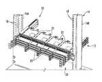
- FIG. 1is a front perspective view of an exemplary fiber optic equipment rack with an installed exemplary 1-RU size chassis supporting high-density fiber optic modules to provide a given fiber optic connection density and bandwidth capability, according to one embodiment;
- FIG. 2is a rear perspective close-up view of the chassis of FIG. 1 with fiber optic modules installed in fiber optic equipment trays installed in the fiber optic equipment;
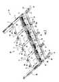
- FIG. 3is a front perspective view of one fiber optic equipment tray with installed fiber optic modules configured to be installed in the chassis of FIG. 1 ;
- FIG. 4is a close-up view of the fiber optic equipment tray of FIG. 3 without fiber optic modules installed;
- FIG. 5is a close-up view of the fiber optic equipment tray of FIG. 3 with fiber optic modules installed;
- FIG. 6is a front perspective view of the fiber optic equipment tray of FIG. 3 without fiber optic modules installed;
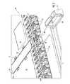
- FIG. 7is a front perspective view of fiber optic equipment trays supporting fiber optic modules with one fiber optic equipment tray extended out from the chassis of FIG. 1 ;
- FIG. 8is a left perspective view of an exemplary tray guide disposed in the chassis of FIG. 1 configured to receive fiber optic equipment trays of FIG. 6 capable of supporting one or more fiber optic modules;
- FIGS. 9A and 9Bare perspective and top views, respectively, of an exemplary tray rail disposed on each side of the fiber optic equipment tray of FIG. 3 and configured to be received in the chassis of FIG. 1 by the tray guide of FIG. 8 ;
- FIGS. 10A and 10Bare front right and left perspective views, respectively, of an exemplary fiber optic module that can be disposed in the fiber optic equipment trays of FIG. 3 ;
- FIG. 11is a perspective, exploded view of the fiber optic module in FIGS. 10A and 10B ;
- FIG. 12is a perspective top view of the fiber optic module of FIG. 11 with the cover removed and showing a fiber optic harness installed therein;
- FIG. 13is a front view of the fiber optic module of FIG. 11 without fiber optic components installed;
- FIG. 14is a front right perspective view of another alternate fiber optic module that supports twelve (12) fiber MPO fiber optic components and which can be installed in the fiber optic equipment tray of FIG. 3 ;
- FIG. 15is front right perspective view of another alternate fiber optic module that supports twenty-four (24) fiber MPO fiber optic components and which can be installed in the fiber optic equipment tray of FIG. 3 ;
- FIG. 16is a front perspective view of an alternate fiber optic module being installed in the fiber optic equipment tray of FIG. 3 ;
- FIG. 17is front right perspective view of the fiber optic module of FIG. 16 ;
- FIG. 18is a front view of the fiber optic module of FIGS. 16 and 17 ;
- FIG. 19is a front perspective view of another alternate fiber optic module being installed in the fiber optic equipment tray of FIG. 3 ;
- FIG. 20is front right perspective view of the fiber optic module of FIG. 19 ;
- FIG. 21is a front view of the fiber optic module of FIGS. 19 and 20 ;
- FIG. 22is a front perspective view of another alternate fiber optic module being installed in an alternate fiber optic equipment tray that can be installed in the chassis of FIG. 1 ;
- FIG. 23is front right perspective view of the fiber optic module of FIG. 22 ;
- FIG. 24is a front view of the fiber optic module of FIGS. 22 and 23 ;
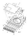
- FIG. 25is a front perspective view of alternate exemplary 4-U size fiber optic chassis that can support the fiber optic equipment trays and fiber optic modules according to the fiber optic equipment tray and fiber optic modules disclosed;
- FIG. 26is a front perspective view of an exemplary 1-U space unit in a fiber optic equipment rack illustrating a fiber optic cable routing region according to an embodiment.
- FIG. 27is a front perspective view of the fiber optic cable routing region of FIG. 26 illustrating optical fibers traversing an incremental section cut in the fiber optic cable routing region.
- Embodiments disclosed in the detailed descriptioninclude high-density fiber optic modules and fiber optic module housings and related equipment.
- the width and/or height of the front opening of fiber optic modules and/or fiber optic module housingscan be provided according to a designed relationship to the width and/or height, respectively, of a front side of the main body of the fiber optic modules and fiber optic module housings to support fiber optic components or connections.
- fiber optic componentscan be installed in a given percentage or area of the front side of the fiber optic module to provide a high density of fiber optic connections for a given fiber optic component type(s).
- the front openings of the fiber optic modules and/or fiber optic module housingscan be provided to support a designed connection density of fiber optic components or connections for a given width and/or height of the front opening of the fiber optic module and/or fiber optic module housing.
- Embodiments disclosed in the detailed descriptionalso include high connection density and bandwidth fiber optic apparatuses and related equipment.
- fiber optic apparatusesare provided and comprise a chassis defining one or more U space fiber optic equipment units, wherein at least one of the one or more U space fiber optic equipment units is configured to support a given fiber optic connection density or bandwidth in a 1-U space, and for a given fiber optic component type(s).
- Embodiments disclosed in the detailed descriptionalso include a fiber optic apparatus comprising a fiber optic equipment rack.
- the fiber optic equipment rackdefines at least one 1-U space fiber optic equipment unit.
- the 1-U space fiber optic equipment unitconfigured to hold fiber optic equipment to which one or more fiber optic cables containing one or more optical fibers connect through at least one LC duplex or simplex, 12 fiber MPO, or 24 fiber MPO fiber optic connector.
- a cable routing regionextends from the at least one 1-U space fiber optic equipment unit, wherein optical fibers are routed in at least a portion of the cable routing region, and wherein the optical fibers maintain a 10 ⁇ 12 bit-error-rate and attenuation limitation of 0.75 dB as set out in TIA/EIA-568 standard in the cable routing region.
- the cable routing regionis configured such that the one or more fiber optic cables make only one bend from the fiber optic connector in the cable routing region and route generally horizontally through the cable routing region.
- fiber optic cablesand/or “optical fibers” include all types of single mode and multi-mode light waveguides, including one or more bare optical fibers, loose-tube optical fibers, tight-buffered optical fibers, ribbonized optical fibers, bend-insensitive optical fibers, or any other expedient of a medium for transmitting light signals.
- FIG. 1illustrates exemplary 1-U size fiber optic equipment 10 from a front perspective view.
- the fiber optic equipment 10supports high-density fiber optic modules that support a high fiber optic connection density and bandwidth in a 1-U space, as will be described in greater detail below.
- the fiber optic equipment 10may be provided at a data distribution center or central office to support cable-to-cable fiber optic connections and to manage a plurality of fiber optic cable connections.
- the fiber optic equipment 10has one or more fiber optic equipment trays that each support one or more fiber optic modules.
- the fiber optic equipment 10could also be adapted to support one or more fiber optic patch panels or other fiber optic equipment that supports fiber optic components and connectivity.
- the fiber optic equipment 10includes a fiber optic equipment chassis 12 (“chassis 12 ”).
- the chassis 12is shown as being installed in a fiber optic equipment rack 14 .
- the fiber optic equipment rack 14contains two vertical rails 16 A, 16 B that extend vertically and include a series of apertures 18 for facilitating attachment of the chassis 12 inside the fiber optic equipment rack 14 .
- the chassis 12is attached and supported by the fiber optic equipment rack 14 in the form of shelves that are stacked on top of each other within the vertical rails 16 A, 16 B. As illustrated, the chassis 12 is attached to the vertical rails 16 A, 16 B.
- the fiber optic equipment rack 14may support 1-RU-sized shelves, with “U” equal to a standard 1.75 inches in height and nineteen (19) inches in width.
- the width of “U”may be twenty-three (23) inches.
- the term fiber optic equipment rack 14should be understood to include structures that are cabinets as well.
- the chassis 12is 1-U in size; however, the chassis 12 could be provided in a size greater than 1-U as well.
- the fiber optic equipment 10includes a plurality of extendable fiber optic equipment trays 20 that each carries one or more fiber optic modules 22 .
- the chassis 12 and fiber optic equipment trays 20support fiber optic modules 22 that support high-density fiber optic modules and a fiber optic connection density and bandwidth connections in a given space, including in a 1-U space.
- FIG. 1shows exemplary fiber optic components 23 disposed in the fiber optic modules 22 that support fiber optic connections.
- the fiber optic components 23may be fiber optic adapters or fiber optic connectors.
- the fiber optic modules 22 in this embodimentcan be provided such that the fiber optic components 23 can be disposed through at least eighty-five percent (85%) of the width of the front side or face of the fiber optic module 22 , as an example.
- This fiber optic module 22 configurationmay provide a front opening of approximately 90 millimeters (mm) or less wherein fiber optic components can be disposed through the front opening and at a fiber optic connection density of at least one fiber optic connection per 7.0 mm of width of the front opening of the fiber optic modules 22 for simplex or duplex fiber optic components 23 .
- six (6) duplex or twelve (12) simplex fiber optic componentsmay be installed in each fiber optic module 22 .
- the fiber optic equipment trays 20 in this embodimentsupport up to four (4) of the fiber optic modules 22 in approximately the width of a 1-U space, and three (3) fiber optic equipment trays 20 in the height of a 1-U space for a total of twelve (12) fiber optic modules 22 in a 1-U space.
- the fiber optic equipment trays 20 in this embodimentsupport up to four (4) of the fiber optic modules 22 in approximately the width of a 1-U space, and three (3) fiber optic equipment trays 20 in the height of a 1-U space for a total of twelve (12) fiber optic modules 22 in a 1-U space.
- a total of one hundred forty-four (144) fiber optic connections, or seventy-two (72) duplex channelsi.e., transmit and receive channels
- duplex fiber optic adaptersare disposed in each of the twelve (12) fiber optic modules 22 installed in fiber optic equipment trays 20 of the chassis 12 , a total of one hundred twenty (120) fiber optic connections, or sixty (60) duplex channels, would be supported by the chassis 12 in a 1-U space.
- the chassis 12also supports at least ninety-eight (98) fiber optic components in a 1-U space wherein at least one of the fiber optic components is a simplex or duplex fiber optic component.
- multi-fiber fiber optic componentswere installed in the fiber optic modules 22 , such as MPO components for example, higher fiber optic connection density and bandwidths would be possible over other chassis 12 that use similar fiber optic components. For example, if up to four (4) twelve (12) fiber MPO fiber optic components were disposed in each fiber optic module 22 , and twelve (12) of the fiber optic modules 22 were disposed in the chassis 12 in a 1-U space, the chassis 12 would support up to five hundred seventy-six (576) fiber optic connections in a 1-U space.
- fiber MPO fiber optic componentswere disposed in each fiber optic module 22 , and twelve (12) of the fiber optic modules 22 were disposed in the chassis 12 , up to one thousand one hundred fifty-two (1152) fiber optic connections in a 1-U space.
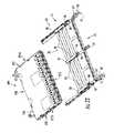
- FIG. 2is a rear perspective close-up view of the chassis 12 of FIG. 1 with fiber optic modules 22 loaded with fiber optic components 23 and installed in fiber optic equipment trays 20 installed in the chassis 12 .
- Module rails 28 A, 28 Bare disposed on each side of each fiber optic module 22 .
- the module rails 28 A, 28 Bare configured to be inserted within tray channels 30 of module rail guides 32 disposed in the fiber optic equipment tray 20 , as illustrated in more detail in FIGS. 3-5 . Note that any number of module rail guides 32 can be provided.
- the fiber optic module 22can be installed from both a front end 34 and a rear end 36 of the fiber optic equipment tray 20 in this embodiment.
- a front end 33 of the fiber optic module 22can be inserted from the rear end 36 of the fiber optic equipment tray 20 . More specifically, the front end 33 of the fiber optic module 22 is inserted into the tray channels 30 of the module rail guides 32 . The fiber optic module 22 can then be pushed forward within the tray channels 30 until the fiber optic module 22 reaches the front end 34 of the module rail guides 32 . The fiber optic modules 22 can be moved towards the front end 34 until the fiber optic modules 22 reach a stop or locking feature disposed in the front end 34 as will described later in this application.
- FIG. 6also illustrates the fiber optic equipment tray 20 without installed fiber optic modules 22 to illustrate the tray channels 30 and other features of the fiber optic equipment tray 20 .
- the fiber optic module 22can be locked into place in the fiber optic equipment tray 20 by pushing the fiber optic module 22 forward to the front end 33 of the fiber optic equipment tray 20 .
- a locking feature in the form of a front stop 38is disposed in the module rail guides 32 , as illustrated in FIG. 3 and in more detail in the close-up view in FIG. 4 .
- the front stop 38prevents the fiber optic module 22 from extending beyond the front end 34 , as illustrated in the close-up view of the fiber optic equipment tray 20 with installed fiber optic modules 22 in FIG. 5 .
- a front module tab 40also disposed in the module rail guides 32 and coupled to the front stop 38 can be pushed downward to engage the front stop 38 .
- the front stop 38will move outward away from the fiber optic module 22 such that the fiber optic module 22 is not obstructed from being pulled forward.
- the fiber optic module 22and in particular its module rails 28 A, 28 B ( FIG. 2 ), can be pulled forward along the module rail guides 32 to remove the fiber optic module 22 from the fiber optic equipment tray 20 .
- the fiber optic module 22can also be removed from the rear end 36 of the fiber optic equipment tray 20 .
- a latch 44is disengaged by pushing a lever 46 (see FIGS. 2 and 3 ; see also, FIGS. 10A and 10B ) inward towards the fiber optic module 22 to release the latch 44 from the module rail guide 32 .
- a finger hook 48is provided adjacent to the lever 46 so the lever 46 can easily be squeezed into the finger hook 48 by a thumb and index finger.
- the fiber optic equipment tray 20may also contain extension members 50 .
- Routing guides 52may be conveniently disposed on the extension members 50 to provide routing for optical fibers or fiber optic cables connected to fiber optic components 23 disposed in the fiber optic modules 22 ( FIG. 3 ).
- the routing guides 52 ′ on the ends of the fiber optic equipment tray 20may be angled with respect to the module rail guides 32 to route optical fibers or fiber optic cables at an angle to the sides of the fiber optic equipment tray 20 .
- Pull tabs 54may also be connected to the extension members 50 to provide a means to allow the fiber optic equipment tray 20 to easily be pulled out from and pushed into the chassis 12 .
- the fiber optic equipment tray 20also contains tray rails 56 .
- the tray rails 56are configured to be received in tray guides 58 disposed in the chassis 12 to retain and allow the fiber optic equipment trays 20 to move in and out of the chassis 12 , as illustrated in FIG. 7 . More detail regarding the tray rails 56 and their coupling to the tray guides 58 in the chassis 12 is discussed below with regard to FIGS. 8 and 9 A- 9 B.
- the fiber optic equipment trays 20can be moved in and out of the chassis 12 by their tray rails 56 moving within the tray guides 58 . In this manner, the fiber optic equipment trays 20 can be independently movable about the tray guides 58 in the chassis 12 .
- FIG. 7illustrates a front perspective view of one fiber optic equipment tray 20 pulled out from the chassis 12 among three (3) fiber optic equipment trays 20 disposed within the tray guides 58 of the chassis 12 .
- the tray guides 58may be disposed on both a left side end 60 and a right side end 62 of the fiber optic equipment tray 20 .
- the tray guides 58are installed opposite and facing each other in the chassis 12 to provide complementary tray guides 58 for the tray rails 56 of the fiber optic equipment trays 20 received therein. If it is desired to access a particular fiber optic equipment tray 20 and/or a particular fiber optic module 22 in a fiber optic equipment tray 20 , the pull tab 54 of the desired fiber optic equipment tray 20 can be pulled forward to cause the fiber optic equipment tray 20 to extend forward out from the chassis 12 , as illustrated in FIG.
- the fiber optic module 22can be removed from the fiber optic equipment tray 20 as previously discussed. When access is completed, the fiber optic equipment tray 20 can be pushed back into the chassis 12 wherein the tray rails 56 move within the tray guides 58 disposed in the chassis 12 .
- FIG. 8is a left perspective view of an exemplary tray guide 58 disposed in the chassis 12 of FIG. 1 .
- the tray guides 58are configured to receive fiber optic equipment trays 20 supporting one or more fiber optic modules 22 in the chassis 12 .
- the tray guides 58allow the fiber optic equipment trays 20 to be pulled out from the chassis 12 , as illustrated in FIG. 7 .
- the tray guide 58 in this embodimentis comprised of a guide panel 64 .
- the guide panel 64may be constructed out of any material desired, including but not limited to a polymer or metal.
- the guide panel 64contains a series of apertures 66 to facilitate attachment of the guide panel 64 to the chassis 12 , as illustrated in FIG. 8 .
- Guide members 68are disposed in the guide panel 64 and configured to receive the tray rail 56 of the fiber optic equipment tray 20 .
- Three (3) guide members 68are disposed in the guide panel 64 in the embodiment of FIG. 8 to be capable of receiving up to three (3) tray rails 56 of three (3) fiber optic equipment trays 20 in a 1-U space.
- any number of guide members 68 desiredmay be provided in the tray guide 58 to cover sizes less than or greater than a 1-RU space.
- the guide members 68each include guide channels 70 configured to receive and allow tray rails 56 to move along the guide channels 70 for translation of the fiber optic equipment trays 20 about the chassis 12 .
- Leaf springs 72are disposed in each of the guide members 68 of the tray guide 58 and are each configured to provide stopping positions for the tray rails 56 during movement of the fiber optic equipment tray 20 in the guide members 68 .
- the leaf springs 72each contain detents 74 that are configured to receive protrusions 76 (FIG. 9 A- 9 D) disposed in the tray rails 56 to provide stopping or resting positions.
- the tray rails 56contain mounting platforms 75 that are used to attach the tray rails 56 to the fiber optic equipment trays 20 . It may be desirable to provide stopping positions in the tray guide 56 to allow the fiber optic equipment trays 20 to have stopping positions when moved in and out of the chassis 12 .
- Two (2) protrusions 76 in the tray rail 56are disposed in two (2) detents 74 in the tray guide 58 at any given time.
- the two (2) protrusions 76 of the tray rail 56are disposed in the one detent 74 adjacent a rear end 77 of the guide channel 70 and the middle detent 74 disposed between the rear end 77 and a front end 78 of the guide channel 70 .
- the two (2) protrusions 76 of the tray rail 56are disposed in the one detent 74 adjacent the front end 78 of the guide channel 70 and the middle detent 74 disposed between the rear end 77 and the front end 78 of the guide channel 70 .
- a protrusion 80 disposed in the tray rail 56 and illustrated in FIGS. 9A and 9Bis biased to pass over transition members 82 disposed between the leaf springs 72 , as illustrated in FIG. 8 .
- the protrusion 80is provided in a leaf spring 81 disposed in the tray rail 56 , as illustrated in FIGS. 9A and 9B .
- the transition members 82have inclined surfaces 84 that allow the protrusion 80 to pass over the transition members 82 as the fiber optic equipment tray 20 is being translated with the guide channel 70 .
- stopping members 86are disposed at the front end 78 and rear end 77 of the guide channel 70 .
- the stopping members 86do not have an inclined surface; thus the protrusion 80 in the tray rail 56 abuts against the stopping member 86 and is prevented from extending over the stopping member 86 and outside of the front end 78 of the guide channel 70 .
- the form factor of the fiber optic module 22allows a high density of fiber optic components 23 to be disposed within a certain percentage area of the front of the fiber optic module 22 thus supporting a particular fiber optic connection density and bandwidth for a given type of fiber optic component 23 .
- this fiber optic module 22 form factoris combined with the ability to support up to twelve (12) fiber optic modules 22 in a 1-U space, as described by the exemplary chassis 12 example above, a higher fiber optic connection density and bandwidth is supported and possible.
- FIGS. 10A and 10Bare right and left perspective views of the exemplary fiber optic module 22 .
- the fiber optic module 22can be installed in the fiber optic equipment trays 20 to provide fiber optic connections in the chassis 12 .
- the fiber optic module 22is comprised of a main body 90 receiving a cover 92 .
- An internal chamber 94FIG. 11 ) disposed inside the main body 90 and the cover 92 and is configured to receive or retain optical fibers or a fiber optic cable harness, as will be described in more detail below.
- the main body 90is disposed between a front side 96 and a rear side 98 of the main body 90 .
- Fiber optic components 23can be disposed through the front side 96 of the main body 90 and configured to receive fiber optic connectors connected to fiber optic cables (not shown).
- the fiber optic components 23are duplex LC fiber optic adapters that are configured to receive and support connections with duplex LC fiber optic connectors.
- any fiber optic connection type desiredcan be provided in the fiber optic module 22 .
- the fiber optic components 23are connected to a fiber optic component 100 disposed through the rear side 98 of the main body 90 . In this manner, a connection to the fiber optic component 23 creates a fiber optic connection to the fiber optic component 100 .
- the fiber optic component 100is a multi-fiber MPO fiber optic adapter equipped to establish connections to multiple optical fibers (e.g., either twelve (12) or twenty-four (24) optical fibers).
- the fiber optic module 22may also manage polarity between the fiber optic components 23 , 100 .
- the module rails 28 A, 28 Bare disposed on each side 102 A, 102 B of the fiber optic module 22 .
- the module rails 28 A, 28 Bare configured to be inserted within the module rail guides 32 in the fiber optic equipment tray 20 , as illustrated in FIG. 3 .
- the front side 96 of the fiber optic module 22can be inserted from either the front end 33 or the rear end 36 of the fiber optic equipment tray 20 , as previously discussed.
- FIG. 11illustrates the fiber optic module 22 in an exploded view with the cover 92 of the fiber optic module 22 removed to illustrate the internal chamber 94 and other internal components of the fiber optic module 22 .
- FIG. 12illustrates the fiber optic module 22 assembled, but without the cover 92 installed on the main body 90 .
- the cover 92includes notches 106 disposed in sides 108 , 110 that are configured to interlock with protrusions 112 disposed on the sides 102 A, 102 B of the main body 90 of the fiber optic modules 22 when the cover 92 is attached to the main body 90 to secure the cover 92 to the main body 90 .
- the cover 92also contains notches 114 , 116 disposed on a front side 118 and rear side 120 , respectively, of the cover 92 .
- the notches 114 , 116are configured to interlock with protrusions 122 , 124 disposed in the front side 96 and the rear end 98 , respectively, of the main body 90 when the cover 92 is attached to the main body 90 to also secure the cover 92 to the main body 90 .
- FIG. 12does not show protrusions 122 , 124 .
- the fiber optic components 23are disposed through a front opening 126 disposed along a longitudinal axis L 1 in the front side 96 of the main body 90 .
- the fiber optic components 23are duplex LC adapters 128 , which support single or duplex fiber connections and connectors.
- the duplex LC adapters 128 in this embodimentcontain protrusions 130 that are configured to engage with orifices 135 disposed on the main body 90 to secure the duplex LC adapters 128 in the main body 90 in this embodiment.
- a cable harness 134is disposed in the internal chamber 94 with fiber optic connectors 136 , 138 disposed on each end of optical fibers 139 connected to the duplex LC adapters 128 and the fiber optic component 100 disposed in the rear side 98 of the main body 90 .
- the fiber optic component 100 in this embodimentis a twelve (12) fiber MPO fiber optic adapter 140 in this embodiment.
- Two vertical members 142 A, 142 Bare disposed in the internal chamber 94 of the main body 90 , as illustrated in FIG. 12 , to retain the looping of the optical fibers 139 of the cable harness 134 .
- the vertical members 142 A, 142 B and the distance betweenare designed to provide a bend radius R in the optical fibers 139 no greater than forty (40) mm and preferably twenty-five (25) mm or less in this embodiment.
- FIG. 13illustrates a front view of the fiber optic module 22 without loaded fiber optic components 23 in the front side 96 to further illustrate the form factor of the fiber optic module 22 .
- the front opening 126is disposed through the front side 96 of the main body 90 to receive the fiber optic components 23 .
- the greater the width W 1 of the front opening 126the greater the number of fiber optic components 23 that may be disposed in the fiber optic module 22 .
- Greater numbers of fiber optic components 23equates to more fiber optic connections, which supports higher fiber optic connectivity and bandwidth.
- the larger the width W 1 of the front opening 126the greater the area required to be provided in the chassis 12 for the fiber optic module 22 .
- the width W 1 of the front opening 126is design to be at least eighty-five percent (85%) of the width W 2 of the front side 96 of the main body 90 of the fiber optic module 22 .
- the greater the percentage of the width W 1 to width W 2the larger the area provided in the front opening 126 to receive fiber optic components 23 without increasing width W 2 .
- Width W 3the overall width of the fiber optic module 22 , may be 86.6 mm or 3.5 inches in this embodiment.
- the overall depth D 1 of the fiber optic module 22is 113.9 mm or 4.5 inches in this embodiment ( FIG. 12 ).
- the fiber optic module 22is designed such that four (4) fiber optic modules 22 can be disposed in a 1-U width space in the fiber optic equipment tray 20 in the chassis 12 .
- the width of the chassis 12is designed to accommodate a 1-U space width in this embodiment.
- a total of twelve (12) fiber optic modules 22can be supported in a given 1-U space.
- Supporting up to twelve (12) fiber optic connections per fiber optic module 22 as illustrated in the chassis 12 in FIG. 1equates to the chassis 12 supporting up to one hundred forty-four (144) fiber optic connections, or seventy-two (72) duplex channels, in a 1-U space in the chassis 12 (i.e., twelve (12) fiber optic connections multiplied by twelve (12) fiber optic modules 22 in a 1-U space).
- the chassis 12is capable of supporting up to one hundred forty-four (144) fiber optic connections in a 1-U space by twelve (12) simplex or six (6) duplex fiber optic adapters being disposed in the fiber optic modules 22 .
- Supporting up to ten (10) fiber optic connections per fiber optic module 22equates to the chassis 12 supporting one hundred twenty (120) fiber optic connections, or sixty (60) duplex channels, in a 1-U space in the chassis 12 (i.e., ten (10) fiber optic connections X twelve (12) fiber optic modules 22 in a 1-U space).
- the chassis 12is also capable of supporting up to one hundred twenty (120) fiber optic connections in a 1-U space by ten (10) simplex or five (5) duplex fiber optic adapters being disposed in the fiber optic modules 22 .
- This embodiment of the chassis 12 and fiber optic module 22 disclosed hereincan support a fiber optic connection density within a 1-U space wherein the area occupied by the fiber optic component 23 in twelve (12) fiber optic modules 22 in a 1-U space represents at least fifty percent (50%) of the total fiber optic equipment rack 14 area in a 1-U space (see FIG. 1 ).
- the 1-U spaceis comprised of the fiber optic components 23 occupying at least seventy-five percent (75%) of the area of the front side 96 of the fiber optic module 22 .
- Two (2) duplexed optical fibers to provide one (1) transmission/reception paircan allow for a data rate of ten (10) Gigabits per second in half-duplex mode or twenty (20) Gigabits per second in full-duplex mode.
- providing at least seventy-two (72) duplex transmission and reception pairs in a 1-U spaceemploying at least one duplex or simplex fiber optic component can support a data rate of at least seven hundred twenty (720) Gigabits per second in half-duplex mode in a 1-U space or at least one thousand four hundred forty (1440) Gigabits per second in a 1-U space in full-duplex mode if employing a ten (10) Gigabit transceiver.
- This configurationcan also support at least six hundred (600) Gigabits per second in half-duplex mode in a 1-U space and at least one thousand two hundred (1200) Gigabits per second in full-duplex mode in a 1-U space, respectively, if employing a one hundred (100) Gigabit transceiver.
- This configurationcan also support at least four hundred eighty (480) Gigabits per second in half-duplex mode in a 1-U space and nine hundred sixty (960) Gigabits per second in full duplex mode in a 1-U space, respectively, if employing a forty (40) Gigabit transceiver.
- At least sixty (60) duplex transmission and reception pairs in a 1-U spacecan allow for a data rate of at least six hundred (600) Gigabits per second in a 1-U space in half-duplex mode or at least one thousand two hundred (1200) Gigabits per second in a 1-U space in full-duplex mode when employing a ten (10) Gigabit transceiver.
- At least forty nine (49) duplex transmission and reception pairs in a 1-U spacecan allow for a data rate of at least four hundred eighty-one (481) Gigabits per second in half-duplex mode or at least nine hundred sixty-two (962) Gigabits per second in a 1-U space in full-duplex mode when employing a ten (10) Gigabit transceiver.
- the width W 1 of front opening 126could be designed to be greater than eighty-five percent (85%) of the width W 2 of the front side 96 of the main body 90 of the fiber optic module 22 .
- the width W 1could be designed to be between ninety percent (90%) and ninety-nine percent (99%) of the width W 2 .
- the width W 1could be less than ninety (90) mm.
- the width W 1could be less than eighty-five (85) mm or less than eighty (80) mm.
- the width W 1may be eighty-three (83) mm and width W 2 may be eighty-five (85) mm, for a ratio of width W 1 to width W 2 of 97.6%.
- the front opening 126may support twelve (12) fiber optic connections in the width W 1 to support a fiber optic connection density of at least one fiber optic connection per 7.0 mm of width W 1 of the front opening 126 .
- the front opening 126 of the fiber optic module 22may support twelve (12) fiber optic connections in the width W 1 to support a fiber optic connection density of at least one fiber optic connection per 6.9 mm of width W 1 of the front opening 126 .
- height H 1 of front opening 126could be designed to be at least ninety percent (90%) of height H 2 of the front side 96 of the main body 90 of the fiber optic module 22 .
- the front opening 126has sufficient height to receive the fiber optic components 23 , and such that three (3) fiber optic modules 22 can be disposed in a 1-U space height.
- height H 1could be twelve (12) mm or less or ten (10) mm or less.
- height H 1could be ten (10) mm and height H 2 could be eleven (11) mm (or 7/16 inches), for a ratio of height H 1 to width H 2 of 90.9%.
- FIG. 14is a front perspective view of an alternate fiber optic module 22 ′ that can be installed in the fiber optic equipment tray 20 of FIG. 1 .
- the form factor of the fiber optic module 22 ′is the same as the form factor of the fiber optic module 22 illustrated in FIGS. 1-13 .
- two (2) MPO fiber optic adapters 150are disposed through the front opening 126 of the fiber optic module 22 ′.
- the MPO fiber optic adapters 150are connected to two (2) MPO fiber optic adapters 152 disposed in the rear side 98 of the main body 90 of the fiber optic module 22 ′.
- the fiber optic module 22 ′can support up to twenty-four (24) fiber optic connections.
- up to twelve (12) fiber optic modules 22 ′are provided in the fiber optic equipment trays 20 of the chassis 12 , up to two hundred eighty-eight (288) fiber optic connections can be supported by the chassis 12 in a 1-U space.
- the front opening 126 of the fiber optic module 22 ′may support twenty-four (24) fiber optic connections in the width W 1 ( FIG. 13 ) to support a fiber optic connection density of at least one fiber optic connection per 3.4-3.5 mm of width W 1 of the front opening 126 .
- a panelmay have one or more adapter on one side and no adapters on the opposite side.
- providing at least two-hundred eighty-eight (288) duplex transmission and reception pairs in a 1-U spaceemploying at least one twelve (12) fiber MPO fiber optic components can support a data rate of at least two thousand eight hundred eighty (2880) Gigabits per second in half-duplex mode in a 1-U space or at least five thousand seven hundred sixty (5760) Gigabits per second in a 1-U space in full-duplex mode if employing a ten (10) Gigabit transceiver.
- This configurationcan also support at least four thousand eight hundred (4800) Gigabits per second in half-duplex mode in a 1-U space and nine thousand six hundred (9600) Gigabits per second in full-duplex mode in a 1-U space, respectively, if employing a one hundred (100) Gigabit transceiver.
- This configurationcan also support at least one thousand nine hundred twenty (1920) Gigabits per second in half-duplex mode in a 1-U space and three thousand eight hundred forty (3840) Gigabits per second in full-duplex mode in a 1-U space, respectively, if employing a forty (40) Gigabit transceiver.
- This configurationalso supports a data rate of at least four thousand three hundred twenty-two (4322) Gigabits per second in full-duplex mode in a 1-U space when employing a ten (10) Gigabit transceiver employing at least one twelve (12) fiber MPO fiber optic component, or two thousand one hundred sixty-one (2161) Gigabits per second in full-duplex mode in a 1-U space when employing a ten (10) Gigabit transceiver employing at least one twenty-four (24) fiber MPO fiber optic component.
- the fiber optic module 22 ′can support up to forty-eight (48) fiber optic connections.
- the fiber optic module 22 ′can support up to twelve (12) fiber optic modules 22 ′ are provided in the fiber optic equipment trays 20 of the chassis 12 , up to five hundred seventy-six (576) fiber optic connections can be supported by the chassis 12 in a 1-U space if the fiber optic modules 22 ′ are disposed in the fiber optic equipment trays 20 .
- the front opening 126 of the fiber optic module 22 ′may support up to forty-eight (48) fiber optic connections in the width W 1 to support a fiber optic connection density of at least one fiber optic connection per 1.7 mm of width W 1 of the front opening 126 .
- FIG. 15is a front perspective view of another alternate fiber optic module 22 ′′ that can be installed in the fiber optic equipment tray 20 of FIG. 1 .
- the form factor of the fiber optic module 22 ′′is the same as the form factor of the fiber optic module 22 illustrated in FIGS. 1-13 .
- four (4) MPO fiber optic adapters 154are disposed through the front opening 126 of the fiber optic module 22 ′′.
- the MPO fiber optic adapters 154are connected to four (4) MPO fiber optic adapters 156 disposed in the rear end 98 of the main body 90 of the fiber optic module 22 ′.
- the fiber optic module 22 ′′can support up to forty-eight (48) fiber optic connections.
- the fiber optic module 22 ′′may support twenty-four (24) fiber optic connections in the width W 1 to support a fiber optic connection density of at least one fiber optic connection per 1.7 mm of width W 1 of the front opening 126 .
- the fiber optic module 22 ′′can support up to ninety-six (96) fiber optic connections.
- the front opening 126 of the fiber optic module 22 ′′may support up to ninety-six (96) fiber optic connections in the width W 1 to support a fiber optic connection density of at least one fiber optic connection per 0.85 mm of width W 1 of the front opening 126 .
- fiber MPO fiber optic componentcan support a data rate of at least five thousand seven hundred sixty (5760) Gigabits per second in half-duplex mode in a 1-U space or at least eleven thousand five hundred twenty (11520) Gigabits per second in a 1-U space in full-duplex mode if employing a ten (10) Gigabit transceiver.
- This configurationcan also support at least four thousand eight hundred (4800) Gigabits per second in half-duplex mode in a 1-U space and at least nine thousand six hundred (9600) Gigabits per second in full-duplex mode in a 1-RU space, respectively, if employing a one hundred (100) Gigabit transceiver.
- This configurationcan also support at least three thousand eight hundred forty (3840) Gigabits per second in half-duplex mode in a 1-U space and at least seven thousand six hundred eighty (7680) Gigabits per second in full-duplex mode in a 1-U space, respectively, if employing a forty (40) Gigabit transceiver.
- This configurationalso supports a data rate of at least eight thousand six hundred forty two (8642) Gigabits per second in full-duplex mode in a 1-U space when employing a ten (10) Gigabit transceiver employing at least one twenty-four (24) fiber MPO fiber optic component, or four thousand three hundred twenty one (4321) Gigabits per second in full-duplex mode in a 1-U space when employing a ten (10) Gigabit transceiver employing at least one twenty-four (24) fiber MPO fiber optic component.
- FIG. 16illustrates an alternate fiber optic module 160 that may be provided in the fiber optic equipment trays 20 to support fiber optic connections and connection densities and bandwidths.
- FIG. 17is a right front perspective view of the fiber optic module 160 of FIG. 16 .
- the fiber optic module 160is designed to fit across two sets of module rail guides 32 .
- a channel 162is disposed through a center axis 164 of the fiber optic module 160 to receive a module rail guide 32 in the fiber optic equipment tray 20 .
- Module rails 165 A, 165 Bsimilar to the module rails 28 A, 28 B of the fiber optic module 22 of FIGS. 1-13 , are disposed on the inside the channel 162 of the fiber optic module 160 and configured to engage with tray channels 30 in the fiber optic equipment tray 20 .
- Module rails 166 A, 166 Bsimilar to the module rails 28 A, 28 B of the fiber optic module 22 of FIGS. 1-13 , are disposed on each side 168 , 170 of the fiber optic module 160 that are configured to engage with tray channels 30 in the fiber optic equipment tray 20 .
- the module rails 166 A, 166 Bare configured to engage with tray channels 30 in a module rail guide 32 disposed between module rail guides 32 engaged with the module rail guides 32 disposed on the sides 168 , 170 of the fiber optic module 160 .
- Up to twenty-four (24) fiber optic components 23can be disposed in a front side 172 of the fiber optic module 160 .
- the fiber optic components 23are comprised of up to twelve (12) duplex LC fiber optic adapters, which are connected to one twenty-four (24) fiber MPO fiber optic connector 174 disposed in a rear end 176 of the fiber optic module 160 .
- the fiber optic components 23are comprised of up to twelve (12) duplex LC fiber optic adapters, which are connected to one twenty-four (24) fiber MPO fiber optic connector 174 disposed in a rear end 176 of the fiber optic module 160 .
- Supporting up to twenty-four (24) fiber optic connections per fiber optic module 160equates to the chassis 12 supporting up to one hundred forty-four (144) fiber optic connections, or seventy-two (72) duplex channels, in a 1-U space in the chassis 12 (i.e., twenty-four (24) fiber optic connections multiplied by six (6) fiber optic modules 160 in a 1-U space).
- the chassis 12is capable of supporting up to one hundred forty-four (144) fiber optic connections in a 1-RU space by twenty-four (24) simplex or twelve (12) duplex fiber optic adapters being disposed in the fiber optic modules 160 .
- Supporting up to twenty (20) fiber optic connections per fiber optic module 160equates to the chassis 12 supporting one hundred twenty (120) fiber optic connections, or sixty (60) duplex channels, in a 1-U space in the chassis 12 (i.e., twenty (20) fiber optic connections multiplied by six (6) fiber optic modules 160 in a 1-U space).
- the chassis 12is also capable of supporting up to one hundred twenty (120) fiber optic connections in a 1-U space by twenty (20) simplex or ten (10) duplex fiber optic adapters being disposed in the fiber optic modules 160 .
- FIG. 18illustrates a front view of the fiber optic module 160 of FIGS. 16-17 without loaded fiber optic components 23 in the front side 172 to further illustrate the form factor of the fiber optic module 160 in this embodiment.
- Front openings 178 A, 178 B disposed on each side of the channel 162are disposed through the front side 172 of a main body 180 of the fiber optic module 160 to receive the fiber optic components 23 .
- the widths W 1 and W 2 and the heights H 1 and H 2are the same as in the fiber optic module 22 illustrated in FIG. 13 .
- the widths W 1 of front openings 178 A, 178 Bare designed to be at least eighty-five percent (85%) of the width W 2 of the front side 172 of the main body 180 of the fiber optic module 160 .
- the greater the percentage of the width W 1 to width W 2the larger the area provided in the front openings 178 A, 178 B to receive fiber optic components 23 without increasing width W 2 .
- the width W 1 of the front openings 178 A, 178 Bcould each be designed to be greater than eighty-five percent (85%) of the width W 2 of the front side 172 of the main body 180 of the fiber optic module 160 .
- the width W 1could be designed to be between ninety percent (90%) and ninety-nine percent (99%) of the width W 2 .
- the width W 1could be less than ninety (90) mm.
- the width W 1could be less than eighty-five (85) mm or less than eighty (80) mm.
- width W 1may be eighty-three (83) mm and width W 2 may be eighty-five (85) mm, for a ratio of width W 1 to width W 2 of 97.6%.
- the front openings 178 A, 178 Bmay support twelve (12) fiber optic connections in the widths W 1 to support a fiber optic connection density of at least one fiber optic connection per 7.0 mm of width W 1 of the front openings 178 A, 178 B.
- each of the front openings 178 A, 178 Bmay support twelve (12) fiber optic connections in the widths W 1 to support a fiber optic connection density of at least one fiber optic connection per 6.9 mm of width W 1 of the front openings 178 A, 178 B.
- the height H 1 of front openings 178 A, 178 Bcould be designed to be at least ninety percent (90%) of the height H 2 of the front side 172 of the main body 180 of the fiber optic module 160 .
- the front openings 178 A, 178 Bhave sufficient height to receive the fiber optic components 23 , while three (3) fiber optic modules 160 can be disposed in the height of a 1-RU space.
- the height H 1could be twelve (12) mm or less or ten (10) mm or less.
- the height H 1could be ten (10) mm and height H 2 could be eleven (11) mm, for a ratio of height H 1 to height H 2 of 90.9%.
- FIG. 19illustrates another alternate fiber optic module 190 that may be provided in the fiber optic equipment trays 20 to support fiber optic connections and connection densities and bandwidths.
- FIG. 20is a right front perspective view of the fiber optic module 190 of FIG. 19 .
- the fiber optic module 190is designed to fit across two sets of module rail guides 32 .
- a longitudinal receiver 192is disposed through a center axis 194 and is configured to receive a module rail guide 32 in the fiber optic equipment tray 20 through an opening 193 in the receiver 192 .
- Module rails 195 A, 195 Bsimilar to the module rails 28 A, 28 B of the fiber optic module 22 of FIGS. 1-13 , are disposed on each side 198 , 200 of the fiber optic module 190 that are configured to engage with tray channels 30 in the fiber optic equipment tray 20 .
- Up to twenty-four (24) fiber optic components 23can be disposed in a front side 202 of the fiber optic module 190 .
- the fiber optic components 23are comprised of up to twelve (12) duplex LC fiber optic adapters, which are connected to one twenty-four (24) fiber MPO fiber optic connector 204 disposed in a rear end 206 of the fiber optic module 190 .
- the fiber optic components 23are comprised of up to twelve (12) duplex LC fiber optic adapters, which are connected to one twenty-four (24) fiber MPO fiber optic connector 204 disposed in a rear end 206 of the fiber optic module 190 .
- Supporting up to twenty-four (24) fiber optic connections per fiber optic module 190equates to the chassis 12 supporting up to one hundred forty-four (144) fiber optic connections, or seventy-two (72) duplex channels, in a 1-U space in the chassis 12 (i.e., twenty-four (24) fiber optic connections multiplied by six (6) fiber optic modules 190 in a 1-U space).
- the chassis 12is capable of supporting up to one hundred forty-four (144) fiber optic connections in a 1-U space by twenty (24) simplex or twelve (12) duplex fiber optic adapters being disposed in the fiber optic modules 190 .
- Supporting up to twenty-four (20) fiber optic connections per fiber optic module 190equates to the chassis 12 supporting one hundred twenty (120) fiber optic connections, or sixty (60) duplex channels, in a 1-U space in the chassis 12 (i.e., twenty (20) fiber optic connections multiplied by six (6) fiber optic modules 190 in a 1-U space).
- the chassis 12is also capable of supporting up to one hundred twenty (120) fiber optic connections in a 1-U space by twenty (20) simplex or ten (10) duplex fiber optic adapters being disposed in the fiber optic modules 190 .
- FIG. 21illustrates a front view of the fiber optic module 190 of FIGS. 19-20 without loaded fiber optic components 23 in the front side 202 to further illustrate the form factor of the fiber optic module 190 .
- Front openings 208 A, 208 Bare disposed on each side of the receiver 192 and through the front side 202 of a main body 210 of the fiber optic module 190 to receive the fiber optic components 23 .
- the widths W 1 and W 2 and the heights H 1 and H 2are the same as in the fiber optic module 22 as illustrated in FIG. 13 .
- the width W 1 of front openings 208 A, 208 Bis designed to be at least eighty-five percent (85%) of the width W 2 of the front side 202 of the main body 210 of the fiber optic module 190 .
- the greater the percentage of the width W 1 to width W 2the larger the area provided in the front openings 208 A, 208 B to receive fiber optic components 23 without increasing the width W 2 .
- the width W 1 of front openings 208 A, 208 Bcould each be designed to be greater than eighty-five percent (85%) of the width W 2 of the front side 202 of the main body 210 of the fiber optic module 190 .
- the width W 1could be designed to be between ninety percent (90%) and ninety-nine percent (99%) of the width W 2 .
- the width W 1could be less than ninety (90) mm.
- the width W 1could be less than eighty-five (85) mm or less than eighty (80) mm.
- width W 1may be eighty-three (83) mm and width W 2 may be eighty-five (85) mm, for a ratio of width W 1 to width W 2 of 97.6%.
- the front openings 208 A, 208 Bmay support twelve (12) fiber optic connections in the widths W 1 to support fiber optic connection density of at least one fiber optic connection per 7.0 mm of width W 1 of the front openings 208 A, 208 B.
- each of the front openings 208 A, 208 Bmay support twelve (12) fiber optic connections in the widths W 1 to support a fiber optic connection density of at least one fiber optic connection per 6.9 mm of width W 1 of the front openings 208 A, 208 B.
- the height H 1 of front openings 208 A, 208 Bcould be designed to be at least ninety percent (90%) of the height H 2 of the front side 202 of the main body 210 of the fiber optic module 190 .
- the front openings 208 A, 208 Bhave sufficient height to receive the fiber optic components 23 , while three (3) fiber optic modules 190 can be disposed in the height of a 1-RU space.
- the height H 1could be twelve (12) mm or less or ten (10) mm or less.
- the height H 1could be ten (10) mm and the height H 2 could be eleven (11) mm, for a ratio of height H 1 to height H 2 of 90.9%.
- FIG. 22illustrates another alternate fiber optic module 220 that may be provided in a fiber optic equipment tray 20 ′ to support a higher number of fiber optic connections and connection densities and bandwidths in a 1-U space.
- the fiber optic equipment tray 20 ′ in this embodimentis similar to the fiber optic equipment tray 20 previously discussed above; however, the fiber optic equipment tray 20 ′ only contains three (3) module rail guides 32 instead of five (5) module rail guides 32 .
- the fiber optic equipment tray 20 ′only supports two fiber optic modules 220 across a 1-RU width space.
- the fiber optic module 220does not have to provide the channel 162 or receiver 192 of the fiber optic modules 160 , 190 , respectively, to be disposed within the fiber optic equipment tray 20 ′.
- FIG. 22illustrates another alternate fiber optic module 220 that may be provided in a fiber optic equipment tray 20 ′ to support a higher number of fiber optic connections and connection densities and bandwidths in a 1-U space.
- the fiber optic equipment tray 20 ′ in this embodimentis similar to the fiber optic equipment
- FIG. 23is a right front perspective view of the fiber optic module 220 of FIG. 22 .
- the fiber optic module 220is designed to fit across one set of module rail guides 32 in the fiber optic equipment tray 20 ′.
- Module rails 225 A, 225 Bsimilar to the module rails 28 A, 28 B of the fiber optic module 22 of FIGS. 1-13 , are disposed on each side 228 , 230 of the fiber optic module 220 that are configured to engage with tray channels 30 in the fiber optic equipment tray 20 ′, as illustrated in FIG. 22 .
- Up to twenty-four (24) fiber optic components 23can be disposed in a front side 232 of the fiber optic module 220 .
- the fiber optic components 23are comprised of up to twelve (12) duplex LC fiber optic adapters, which are connected to one twenty-four (24) fiber MPO fiber optic connector 234 disposed in a rear end 236 of the fiber optic module 220 .
- the fiber optic components 23are comprised of up to twelve (12) duplex LC fiber optic adapters, which are connected to one twenty-four (24) fiber MPO fiber optic connector 234 disposed in a rear end 236 of the fiber optic module 220 .
- Supporting up to twenty-four (24) fiber optic connections per fiber optic module 220equates to the chassis 12 supporting up to one hundred forty-four (144) fiber optic connections, or seventy-two (72) duplex channels, in a 1-U space in the chassis 12 (i.e., twenty-four (24) fiber optic connections multiplied by six (6) fiber optic modules 220 in a 1-U space).
- the chassis 12is capable of supporting up to one hundred forty-four (144) fiber optic connections in a 1-RU space by twenty (24) simplex or twelve (12) duplex fiber optic adapters being disposed in the fiber optic modules 220 .
- Supporting up to twenty (20) fiber optic connections per fiber optic module 220equates to the chassis 12 supporting one hundred twenty (120) fiber optic connections, or sixty (60) duplex channels, in a 1-RU space in the chassis 12 (i.e., twenty (20) fiber optic connections multiplied by six (6) fiber optic modules 220 in a 1-U space).
- the chassis 12is also capable of supporting up to one hundred twenty (120) fiber optic connections in a 1-U space by twenty (20) simplex or ten (10) duplex fiber optic adapters being disposed in the fiber optic modules 220 .
- FIG. 24illustrates a front view of the fiber optic module 220 of FIGS. 22-23 without loaded fiber optic components 23 in the front side 232 to further illustrate the form factor of the fiber optic module 220 in this embodiment.
- a front opening 238is through the front side 232 of a main body 240 of the fiber optic module 220 to receive the fiber optic components 23 .
- Width W 4 of the front opening 238is twice the width W 1 of the front opening 98 in the fiber optic module 22 illustrated in FIG. 13 .
- Width W 5 of the front side 232is about one-hundred eighty-eight (188) millimeters, which is slightly greater than about twice the width W 3 of the fiber optic module 22 illustrated in FIG. 13 .
- the width W 4 of the front opening 238is designed to be at least eighty-five percent (85%) of the width W 5 of the front side 232 of the main body 240 of the fiber optic module 220 .
- the greater the percentage of the width W 4 to the width W 5the larger the area provided in the front opening 238 to receive fiber optic components 23 without increasing the width W 4 .
- Width W 4 of the front opening 238could be designed to be greater than eighty-five percent (85%) of the width W 5 of the front side 232 of the main body 240 of the fiber optic module 220 .
- the width W 4could be designed to be between ninety percent (90%) and ninety-nine percent (99%) of the width of W 5 .
- the width W 4could be less than one hundred eighty (180) mm.
- the width W 4could be less than one hundred seventy (170) mm or less than one hundred sixty (160) mm.
- the front opening 238may support twenty-four (24) fiber optic connections in the width W 4 to support a fiber optic connection density of at least one fiber optic connection per 7.0 mm of width W 4 of the front opening 238 .
- the front opening 238may support twenty-four (24) fiber optic connections in the width W 4 to support a fiber optic connection density of at least one fiber optic connection per 6.9 mm of width W 4 of the front opening 238 .
- the height H 1 of the front opening 238could be designed to be at least ninety percent (90%) of the height H 2 of the front side 232 of the main body 240 of the fiber optic module 220 .
- the front opening 238has sufficient height to receive the fiber optic components 23 , while three (3) fiber optic modules 220 can be disposed in the height of a 1-RU space.
- the height H 1could be twelve (12) mm or less or ten (10) mm or less.
- the height H 1could be ten (10) mm and height H 2 could be eleven (11) mm, for a ratio of height H 1 to height H 2 of 90.9%.
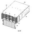
- FIG. 25illustrates another embodiment of fiber optic equipment 260 that can include fiber optic equipment trays previously described above and illustrated to support fiber optic modules.
- the fiber optic equipment 260 in this embodimentincludes a 4-U sized chassis 262 configured to hold fiber optic equipment trays each supporting one or more fiber optic modules.
- the supported fiber optic equipment traysmay be any of the fiber optic equipment trays 20 , 20 ′ previously described above and thus will not be described again here.
- the supported fiber optic modulesmay be any of the fiber optic modules 22 , 22 ′, 22 ′′, 160 , 190 , 220 previously described above and thus will not be described again here.
- the chassis 262is illustrated as supporting twelve (12) fiber optic equipment trays 20 each capable of supporting fiber optic modules 22 .
- the tray guides 58 previously describedare used in the chassis 262 to support tray rails 56 of the fiber optic equipment trays 20 therein and to allow each fiber optic equipment tray 20 to be independently extended out from and retracted back into the chassis 262 .
- a front door 264is attached to the chassis 262 and is configured to close about the chassis 262 to secure the fiber optic equipment trays 20 contained in the chassis 262 .
- a cover 266is also attached to the chassis 262 to secure the fiber optic equipment trays 20 .
- up to twelve (12) fiber optic equipment trays 20can be provided.
- the fiber optic connection densities and connection bandwidthsare still the same per 1-U space.
- the fiber optic connection densities and connection bandwidth capabilitieshave been previously described and equally applicable for the chassis 262 of FIG. 25 , and thus will not be described again here.
- two (2) optical fibers duplexed for one (1) transmission/reception paircan allow for a data rate of ten (10) Gigabits per second in half-duplex mode or twenty (20) Gigabits per second in full-duplex mode.
- optical fibers in a twelve (12) fiber MPO fiber optic connector duplexed for four (4) transmission/reception pairscan allow for a data rate of forty (40) Gigabits per second in half-duplex mode or eighty (80) Gigabits per second in full-duplex mode.
- twenty optical fibers in a twenty-four (24) fiber MPO fiber optic connector duplexed for ten (10) transmission/reception pairscan allow for a data rate of one hundred (100) Gigabits per second in half-duplex mode or two hundred (200) Gigabits per second in full-duplex mode. Note that this table is exemplary and the embodiments disclosed herein are not limited to the fiber optic connection densities and bandwidths provided below.
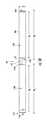
- FIG. 26illustrates a 1-U fiber optic cable routing region 300 which provides for high fiber optic cable packing density.
- the 1-U fiber optic cable routing region 300is depicted in front of a 1-U chassis having fiber optic equipment trays supporting modules with LC duplex adapters, it should be understood that the discussion of the 1-U fiber optic cable routing region 300 applies to embodiments having fiber optic equipment of any U size, with any type adapters, whether or not contained in a module, and any size or type of module.
- multiple U sized fiber optic equipmentwill have an equivalent number of 1-U fiber optic cable routing regions 300 .
- the 1-U fiber optic cable routing region 300is defined by width, height and depth dimensions.
- the width dimension designated in FIG. 26 as “X” in this embodimentmay be about 16.17 inches.
- the height dimension designated in FIG. 26 as “Y”may be about 1.45 inches.
- the depth dimension designated in FIG. 26 as “Z”may be about 3.38 inches.
- the fiber optic cables 310 within the 1-U fiber optic cable routing region 300may include one or more fiber optic cables connecting to connectors on the fiber optic equipment located in that 1-U space and fiber optic cables traversing that 1-U space for connection to other fiber optic equipment. Nonetheless, all of such fiber optic cables 310 may be routed in a generally horizontal direction within the 1-U fiber optic cable routing region 300 . This allows the fiber optic cables 310 that are connected to connectors on the fiber optic equipment located in that 1-U space to make one bend before routing out of the 1-U fiber optic cable routing regions 300 . Once a fiber optic cable 310 exits the 1-U fiber optic cable routing regions 300 , it will make a vertical bend, either upwardly or downwardly, to route in and/or from the fiber optic equipment rack 14 . In this manner, the fiber optic cable 310 may make no more than two bends before routing out of the fiber optic equipment rack 14 .
- BERbit-error-rate
- attenuation limitsBy using bend-insensitive fiber, more fiber can be packed into the 1-U fiber optic cable routing regions 300 without exceeding bit-error-rate (BER) and attenuation limits. In other words, tighter bends are allowable such that a fiber optic cable 310 connecting to a connector in the 1-U space occupies less depth or “Z” dimension.
- the acceptable maximum BER for data transmissionis 10 ⁇ 12 and the acceptable maximum attenuation is 0.75 dB as established by the TIA/EIA-568 standard.
- the BER limit and the attenuation limithereinafter in this disclosure referred to as the BER limit and the attenuation limit.
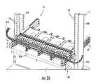
- the 1-U fiber optic cable routing region 300is shown removed from in front of the 1-U space.
- a representative example of optical fibers 312 schematically depicted as extracted from the fiber optic cables 310is shown routing in the 1-U fiber optic cable routing region 300 .
- the optical fibers 312are shown traversing an incremental section 314 vertically cut through 1-U fiber optic cable routing region 300 .
- One or more of the optical fibersmay be contained in one or more fiber optic cables 310 that connect to connections on fiber optic equipment in the particular 1-U space of the 1-U fiber optic cable routing region 300 .
- At least about 98 optical fibers 312may traverse the incremental section 314 of the 1-U fiber optic cable routing region 300 without exceeding BER and/or attenuation limits. In other words, at least 98 optical fibers 312 may route per 1-U shelf space without exceeding the BER and/or the attenuation limits. Further, in this case, between about 98 optical fibers 312 and about 144 optical fibers 312 may traverse the incremental section 314 of the 1-U fiber optic cable routing region 300 without exceeding the BER and/or the attenuation limits.
- At least about 434 optical fibers 312may traverse the incremental section 314 of the 1-U fiber optic cable routing region 300 without exceeding BER and/or attenuation limits. In other words, at least 434 optical fibers 312 may route per 1-U shelf space without exceeding the BER and/or the attenuation limits. Further, in this case, between about 434 optical fibers 312 and about 576 optical fibers 312 may traverse the incremental section 314 of the 1-U fiber optic cable routing region 300 without exceeding the BER and/or the attenuation limits.
- At least about 866 optical fibers 312may traverse the incremental section 314 of the 1-U fiber optic cable routing region 300 without exceeding the BER and/or the attenuation limits.
- at least 866 optical fibers 312may route per 1-U shelf space without exceeding the BER and/or the attenuation limits.
- between about 866 optical fibers 312 and about 1152 optical fibers 312may traverse the incremental section 314 of the 1-U fiber optic cable routing region 300 without exceeding the BER and/or the attenuation limits.
- At least about 1152 optical fibers 312may traverse the incremental section 314 of the 1-U fiber optic cable routing region 300 without exceeding the BER and/or the attenuation limits. In other words, at least 1152 optical fibers 312 may route per 1-U shelf space without exceeding the BER and/or the attenuation limits.
- fiber optic cablesand/or “optical fibers” include all types of single mode and multi-mode light waveguides, including one or more optical fibers that may be upcoated, colored, buffered, ribbonized and/or have other organizing or protective structure in a cable such as one or more tubes, strength members, jackets or the like.
- other types of suitable optical fibersinclude bend-insensitive optical fibers, or any other expedient of a medium for transmitting light signals.
- An example of a bend-insensitive optical fiberis ClearCurve® Multimode fiber commercially available from Corning Incorporated.
Landscapes
- Physics & Mathematics (AREA)
- General Physics & Mathematics (AREA)
- Optics & Photonics (AREA)
- Light Guides In General And Applications Therefor (AREA)
Abstract
Description
| Max | Max | Number of | Number of | Bandwidth per 1U | Bandwidth per 1U | Bandwidth per 1U | |
| Fibers | Fibers | Connectors | Connectors | using 10 Gigabit | using 40 Gigabit | using 100 Gigabit | |
| Connector | per | per | per 1 RU | per 4 RU | Transceivers | Transceivers | Transceivers |
| Type | 1RU | 4RU | Space | Space | (duplex) | (duplex) | (duplex) |
| Duplexed | 144 | 576 | 72 | 288 | 1,440 Gigabits/s. | 960 Gigabits/s. | 1,200 Gigabits/s. |
| LC | |||||||
| 12-F MPO | 576 | 2,304 | 48 | 192 | 5,760 Gigabits/s. | 3,840 Gigabits/s. | 4,800 Gigabits/s. |
| 24-F MPO | 1,152 | 4,608 | 48 | 192 | 11,520 Gigabits/s. | 7,680 Gigabits/s. | 9,600 Gigabits/s. |
16.17 inches×1.45 inches×3.38 inches=79.25 in.3
Claims (64)
Priority Applications (1)
| Application Number | Priority Date | Filing Date | Title |
|---|---|---|---|
| US12/819,034US8433171B2 (en) | 2009-06-19 | 2010-06-18 | High fiber optic cable packing density apparatus |
Applications Claiming Priority (2)
| Application Number | Priority Date | Filing Date | Title |
|---|---|---|---|
| US21887809P | 2009-06-19 | 2009-06-19 | |
| US12/819,034US8433171B2 (en) | 2009-06-19 | 2010-06-18 | High fiber optic cable packing density apparatus |
Publications (2)
| Publication Number | Publication Date |
|---|---|
| US20100322581A1 US20100322581A1 (en) | 2010-12-23 |
| US8433171B2true US8433171B2 (en) | 2013-04-30 |
Family
ID=42732804
Family Applications (1)
| Application Number | Title | Priority Date | Filing Date |
|---|---|---|---|
| US12/819,034Active2031-03-10US8433171B2 (en) | 2009-06-19 | 2010-06-18 | High fiber optic cable packing density apparatus |
Country Status (7)
| Country | Link |
|---|---|
| US (1) | US8433171B2 (en) |
| EP (1) | EP2443498B1 (en) |
| JP (1) | JP2012530943A (en) |
| CN (1) | CN102804014A (en) |
| AU (1) | AU2010263046B2 (en) |
| CA (1) | CA2765830A1 (en) |
| WO (1) | WO2010148325A1 (en) |
Cited By (24)
| Publication number | Priority date | Publication date | Assignee | Title |
|---|---|---|---|---|
| US20140238945A1 (en)* | 2013-02-26 | 2014-08-28 | Realm Communications Group, Inc. | Distribution panel with dual movable trays |
| US9257788B1 (en)* | 2015-01-23 | 2016-02-09 | Oracle International Corporation | Connector retention and alignment assembly for use in computer and data storage mounting racks |
| US20160085042A1 (en)* | 2014-09-24 | 2016-03-24 | Champion Optical Network Engineering, Llc | High-density modular wdm system - high density passive fiber module (pfm), tray and chassis interchangeable solution |
| US9329353B2 (en)* | 2011-10-07 | 2016-05-03 | Commscope Technologies Llc | Slidable fiber optic connection module with cable slack management |
| US9420715B2 (en)* | 2012-06-07 | 2016-08-16 | Intal Tech Ltd. | Electrononic equipment building blocks for rack mounting |
| US9494758B2 (en) | 2014-04-03 | 2016-11-15 | Commscope Technologies Llc | Fiber optic distribution system |
| US9523833B2 (en) | 2013-02-05 | 2016-12-20 | Commscope Technologies Llc | Slidable telecommunications tray with cable slack management |
| US20170131493A1 (en)* | 2013-03-05 | 2017-05-11 | Finisar Corporation | Latch mechanism for communication module |
| US9690065B2 (en) | 2014-09-12 | 2017-06-27 | Panduit Corp. | High density fiber enclosure and method |
| US10215944B2 (en) | 2016-06-30 | 2019-02-26 | Panduit Corp. | Modular fiber optic tray |
| US10495833B2 (en) | 2012-09-21 | 2019-12-03 | Commscope Technologies Llc | Slidable fiber optic connection module with cable slack management |
| US10539757B2 (en) | 2016-04-19 | 2020-01-21 | Commscope, Inc. Of North Carolina | Telecommunications chassis with slidable trays |
| US10670822B2 (en) | 2017-06-28 | 2020-06-02 | Afl Telecommunications Llc | High density patch panel with modular cassettes |
| US11237348B2 (en) | 2019-04-17 | 2022-02-01 | Afl Ig Llc | Patch panel with lifting cassette removal |
| US11256054B2 (en) | 2018-04-16 | 2022-02-22 | Commscope Technologies Llc | Adapter structure |
| US11327263B2 (en) | 2019-04-01 | 2022-05-10 | Afl Telecommunications Lcc | Fiber optic tray systems |
| US11343937B2 (en)* | 2020-03-03 | 2022-05-24 | Ezconn Corporation | Modular high density communications chassis |
| US11372186B2 (en) | 2017-04-04 | 2022-06-28 | Commscope Technologies Llc | Optical splice and termination module |
| US11385429B2 (en) | 2017-10-18 | 2022-07-12 | Commscope Technologies Llc | Fiber optic connection cassette |
| US11674345B2 (en) | 2016-04-19 | 2023-06-13 | Commscope, Inc. Of North Carolina | Door assembly for a telecommunications chassis with a combination hinge structure |
| US11740421B2 (en) | 2021-02-18 | 2023-08-29 | Commscope Technologies Llc | Communications panel system |
| US11852882B2 (en) | 2018-02-28 | 2023-12-26 | Commscope Technologies Llc | Packaging assembly for telecommunications equipment |
| US11971598B2 (en) | 2021-02-18 | 2024-04-30 | Commscope Technologies Llc | Tray arrangements for cassettes |
| EP4498141A1 (en)* | 2023-07-28 | 2025-01-29 | Rosenberger-OSI GmbH & Co. OHG | Rail assembly, beam assembly and fiber optic distribution system |
Families Citing this family (35)
| Publication number | Priority date | Publication date | Assignee | Title |
|---|---|---|---|---|
| US11294136B2 (en) | 2008-08-29 | 2022-04-05 | Corning Optical Communications LLC | High density and bandwidth fiber optic apparatuses and related equipment and methods |
| US8452148B2 (en) | 2008-08-29 | 2013-05-28 | Corning Cable Systems Llc | Independently translatable modules and fiber optic equipment trays in fiber optic equipment |
| US9075216B2 (en) | 2009-05-21 | 2015-07-07 | Corning Cable Systems Llc | Fiber optic housings configured to accommodate fiber optic modules/cassettes and fiber optic panels, and related components and methods |
| EP2443497B1 (en) | 2009-06-19 | 2020-03-04 | Corning Cable Systems LLC | High density and bandwidth fiber optic apparatus |
| US8992099B2 (en) | 2010-02-04 | 2015-03-31 | Corning Cable Systems Llc | Optical interface cards, assemblies, and related methods, suited for installation and use in antenna system equipment |
| US8913866B2 (en) | 2010-03-26 | 2014-12-16 | Corning Cable Systems Llc | Movable adapter panel |
| CA2796221C (en) | 2010-04-16 | 2018-02-13 | Ccs Technology, Inc. | Sealing and strain relief device for data cables |
| US9519118B2 (en) | 2010-04-30 | 2016-12-13 | Corning Optical Communications LLC | Removable fiber management sections for fiber optic housings, and related components and methods |
| US8879881B2 (en) | 2010-04-30 | 2014-11-04 | Corning Cable Systems Llc | Rotatable routing guide and assembly |
| US9075217B2 (en) | 2010-04-30 | 2015-07-07 | Corning Cable Systems Llc | Apparatuses and related components and methods for expanding capacity of fiber optic housings |
| CA2799225C (en) | 2010-05-14 | 2016-10-11 | Afl Telecommunications Llc | Fiber optic cable management module and panel |
| US9279951B2 (en) | 2010-10-27 | 2016-03-08 | Corning Cable Systems Llc | Fiber optic module for limited space applications having a partially sealed module sub-assembly |
| CA2819235C (en) | 2010-11-30 | 2018-01-16 | Corning Cable Systems Llc | Fiber device holder and strain relief device |
| WO2012106510A2 (en) | 2011-02-02 | 2012-08-09 | Corning Cable Systems Llc | Dense fiber optic connector assemblies and related connectors and cables suitable for establishing optical connections for optical backplanes in equipment racks |
| US8556356B2 (en) | 2011-02-21 | 2013-10-15 | Commscope, Inc. Of North Carolina | Communication shelf having supports for pivotable adapter panels and method of mounting adapter panels therein |
| US9008485B2 (en) | 2011-05-09 | 2015-04-14 | Corning Cable Systems Llc | Attachment mechanisms employed to attach a rear housing section to a fiber optic housing, and related assemblies and methods |
| AU2012275598A1 (en) | 2011-06-30 | 2014-01-16 | Corning Optical Communications LLC | Fiber optic equipment assemblies employing non-U-width-sized housings and related methods |
| US8953924B2 (en) | 2011-09-02 | 2015-02-10 | Corning Cable Systems Llc | Removable strain relief brackets for securing fiber optic cables and/or optical fibers to fiber optic equipment, and related assemblies and methods |
| US9038832B2 (en) | 2011-11-30 | 2015-05-26 | Corning Cable Systems Llc | Adapter panel support assembly |
| US20130308916A1 (en)* | 2012-05-16 | 2013-11-21 | Scott Eaker Buff | High-density port tap fiber optic modules, and related systems and methods for monitoring optical networks |
| US9250409B2 (en) | 2012-07-02 | 2016-02-02 | Corning Cable Systems Llc | Fiber-optic-module trays and drawers for fiber-optic equipment |
| US20140010510A1 (en)* | 2012-07-03 | 2014-01-09 | Stephen R. Blackard | Optical fiber connectivity management system |
| US9042702B2 (en) | 2012-09-18 | 2015-05-26 | Corning Cable Systems Llc | Platforms and systems for fiber optic cable attachment |
| ES2551077T3 (en) | 2012-10-26 | 2015-11-16 | Ccs Technology, Inc. | Fiber optic management unit and fiber optic distribution device |
| US8985862B2 (en) | 2013-02-28 | 2015-03-24 | Corning Cable Systems Llc | High-density multi-fiber adapter housings |
| US9885845B2 (en)* | 2015-01-15 | 2018-02-06 | Commscope, Inc. Of North Carolina | Module and assembly for fiber optic interconnections |
| DE102015118338A1 (en)* | 2015-10-27 | 2017-04-27 | Reichle & De-Massari Ag | Patch panel device and modular system for producing a patch panel device |
| JP6438426B2 (en)* | 2016-03-30 | 2018-12-12 | Seiオプティフロンティア株式会社 | Optical switching unit and optical switching device |
| JP6741929B2 (en) | 2016-06-09 | 2020-08-19 | 住友電工オプティフロンティア株式会社 | Multi-core single-core conversion module and multi-core single-core conversion device |
| USD820234S1 (en)* | 2016-07-11 | 2018-06-12 | Leader Optec Limited | Telecommunications apparatus |
| CA3019081A1 (en) | 2017-10-03 | 2019-04-03 | Belden Canada Inc. | Modular fiber optic cassette, system and method |
| CN113885138A (en) | 2020-07-01 | 2022-01-04 | 罗森伯格高频技术有限及两合公司 | Fiber Optic Modules, Fiber Optic Module Kits, and Optical Distribution Frames |
| DE102020126734B4 (en) | 2020-10-12 | 2024-06-13 | Zellner Gmbh | System insert with swiveling connector coupling piece |
| JP7457206B2 (en)* | 2021-04-23 | 2024-03-27 | 株式会社フジクラ | optical termination box |
| EP4350409B1 (en)* | 2022-10-07 | 2024-07-24 | Rosenberger-OSI GmbH & Co. OHG | Module assembly, support unit and support assembly for optical fibre distribution technology |
Citations (642)
| Publication number | Priority date | Publication date | Assignee | Title |
|---|---|---|---|---|
| US620013A (en) | 1899-02-21 | Medicine-case | ||
| US3175873A (en) | 1961-06-09 | 1965-03-30 | Fmc Corp | Panel locking mechanism for console type structures |
| US3906592A (en) | 1974-04-25 | 1975-09-23 | Nissan Motor | Wiring or piping clamp |
| US4059872A (en) | 1975-11-24 | 1977-11-29 | Domenico Delesandri | Hose clamp assembly |
| FR2378378A1 (en) | 1977-01-21 | 1978-08-18 | Bunker Ramo | MODULAR INTERCONNECTION DEVICE |
| US4285486A (en) | 1979-07-12 | 1981-08-25 | Jewell Von Osten | Cord holder |
| US4354731A (en) | 1979-10-02 | 1982-10-19 | E. I. Du Pont De Nemours And Company | Self-aligning optical fiber connector |
| US4597173A (en) | 1984-06-20 | 1986-07-01 | The United States Of America As Represented By The Secretary Of The Navy | Electronic module insertion and retraction mechanism |
| US4611875A (en) | 1984-08-23 | 1986-09-16 | At&T Information Systems | Communication system cross-connect field power adapter |
| US4645292A (en) | 1983-08-03 | 1987-02-24 | Siemens Aktiengesellschaft | Device for facilitating connecting light waveguides in a connector for a multiple light waveguide |
| DE8711970U1 (en) | 1987-09-04 | 1987-10-15 | kabelmetal electro GmbH, 3000 Hannover | Cable termination device for optical fibers |
| US4702551A (en) | 1984-10-11 | 1987-10-27 | Reliance Comm/Tec Corporation | Method and apparatus for handling and storing cabled spliced ends of fiber optics |
| EP0250900A2 (en) | 1986-06-25 | 1988-01-07 | Siemens Aktiengesellschaft | Distributor for telecommunication arrangements with light wave guides |
| US4736100A (en) | 1986-07-31 | 1988-04-05 | Amp Incorporated | Optical loop attenuator simulating an optical system |
| US4747020A (en) | 1986-05-16 | 1988-05-24 | Adc Telecommunications, Inc. | Wire distribution apparatus |
| US4752110A (en) | 1985-11-18 | 1988-06-21 | Alcatel | Cabinet for an optical cable head |
| US4792203A (en) | 1985-09-17 | 1988-12-20 | Adc Telecommunications, Inc. | Optical fiber distribution apparatus |
| US4798432A (en) | 1985-09-11 | 1989-01-17 | U.S. Philips Corp. | Storage container for a section of a light conducting fibre |
| DE3726719A1 (en) | 1986-04-07 | 1989-02-23 | Siemens Ag | DEVICE FOR ATTACHING A MECHANICAL CONNECTION TO THE CABLE SHEATH OF AN OPTICAL CABLE |
| DE3726718A1 (en) | 1986-04-07 | 1989-02-23 | Siemens Ag | DEVICE FOR ATTACHING A MECHANICAL CONNECTION TO THE CABLE SHEATH OF AN OPTICAL CABLE |
| US4808774A (en) | 1987-10-19 | 1989-02-28 | Gte Products Corporation | Strain relief device |
| US4824193A (en) | 1985-07-26 | 1989-04-25 | Matsushita Electric Industrial Co., Ltd. | Holographic multiplexer/demultiplexer and its manufacturing method |
| US4824196A (en) | 1987-05-26 | 1989-04-25 | Minnesota Mining And Manufacturing Company | Optical fiber distribution panel |
| US4826277A (en) | 1987-10-30 | 1989-05-02 | Amp Incorporated | Transition of a multiple fiber cable to single fiber cable |
| US4838643A (en)* | 1988-03-23 | 1989-06-13 | Alcatel Na, Inc. | Single mode bend insensitive fiber for use in fiber optic guidance applications |
| US4865280A (en) | 1988-11-25 | 1989-09-12 | Phillips Plastics Corporation | One-piece wire retainer clip with expandable fastener for securing elongated members to a structure |
| US4898448A (en) | 1988-05-02 | 1990-02-06 | Gte Products Corporation | Fiber distribution panel |
| US4900123A (en) | 1988-08-29 | 1990-02-13 | Gte Products Corporation | 1550 nm fiber distribution panel |
| US4911662A (en) | 1988-12-20 | 1990-03-27 | Northern Telecom Limited | Distribution frame for telecommunications cable |
| US4948220A (en) | 1988-06-20 | 1990-08-14 | Societe Anonyme De Telecommunications | Module for distributing and connecting optical fibers |
| US4949376A (en) | 1989-06-15 | 1990-08-14 | Keptel, Inc. | Telephone network interface apparatus |
| US4971421A (en) | 1989-09-29 | 1990-11-20 | Reliance Comm/Tec Corporation | Fiber optic splice and patch enclosure |
| EP0408266A2 (en) | 1989-07-11 | 1991-01-16 | BICC Public Limited Company | Termination system for optical fibres |
| US4991928A (en) | 1990-02-20 | 1991-02-12 | Siecor Corporation | Movable clamp for fiber optic enclosures |
| US4995688A (en) | 1989-07-31 | 1991-02-26 | Adc Telecommunications, Inc. | Optical fiber distribution frame |
| US5001602A (en) | 1988-11-28 | 1991-03-19 | Reliance Comm/Tec Corporation | Network interface cabinet for large pair count telephone terminations |
| US5005941A (en) | 1989-09-05 | 1991-04-09 | Gte Products Corporation | Fiber optic splice assembly |
| WO1991005281A1 (en) | 1989-09-29 | 1991-04-18 | Northern Telecom Limited | Connector holders and distribution frame and connector holder assemblies for optical cable |
| US5017211A (en) | 1987-09-23 | 1991-05-21 | Ciba-Geigy Corporation | Heterocyclic compounds |
| US5023646A (en) | 1985-12-27 | 1991-06-11 | Minolta Camera Kabushiki Kaisha | Automatic focus detection system |
| US5024498A (en) | 1988-11-12 | 1991-06-18 | U.S. Philips Corp. | Switch box for producing freely selectable optical plug connections |
| US5028114A (en) | 1988-09-29 | 1991-07-02 | Siemens Aktiengesellschaft | Plug connector for fiber optic cables |
| JPH03172806A (en) | 1989-12-01 | 1991-07-26 | Nippon Telegr & Teleph Corp <Ntt> | Optical connector |
| US5037175A (en) | 1990-06-11 | 1991-08-06 | Amp Incorporated | Clip for dressing of fiber optic cable within confined space |
| GB2241591A (en) | 1990-02-28 | 1991-09-04 | Optical Data Communications Li | Mounting frames for fibre optic or electrical cable organiser trays |
| US5048918A (en) | 1990-02-07 | 1991-09-17 | Raychem Corporation | Optical fiber cable termination |
| US5066149A (en) | 1990-09-11 | 1991-11-19 | Adc Telecommunications, Inc. | Splice tray with slack take-up |
| US5067784A (en) | 1990-11-19 | 1991-11-26 | George Debortoli | Connector holders |
| US5071220A (en) | 1989-05-11 | 1991-12-10 | L'etat Francais Represente Par Le Ministre Des Postes, Des Telecommunications Et Des L'espace (Centre National D'etudes Des Telecommunications) | Joint closure module and box for optical fiber cables |
| US5071211A (en) | 1988-12-20 | 1991-12-10 | Northern Telecom Limited | Connector holders and distribution frame and connector holder assemblies for optical cable |
| JPH03279474A (en) | 1990-03-28 | 1991-12-10 | Achilles Corp | Sheet-like material having leather-type appearance |
| US5073042A (en) | 1990-06-21 | 1991-12-17 | Amp Incorporated | Coupling bushing for various types of optical fiber connectors |
| US5074635A (en) | 1990-05-21 | 1991-12-24 | Minnesota Mining And Manufacturing Company | Splice tray and method |
| US5076688A (en) | 1990-03-23 | 1991-12-31 | Amp Incorporated | Optical simulator with loop-back attenuator having metalized optical fiber |
| US5080459A (en) | 1987-12-23 | 1992-01-14 | British Telecommunications Public Limited Company | Mounting assembly for optical equipment |
| EP0468671A1 (en) | 1990-07-27 | 1992-01-29 | The Whitaker Corporation | Fiber optic interconnect for wall outlet |
| EP0474091A1 (en) | 1990-09-03 | 1992-03-11 | Reichle + De-Massari AG Elektro-Ingenieure | Pothead device for signal transmission cables, particularly for glass fibres cables |
| DE4030301A1 (en) | 1990-09-25 | 1992-03-26 | Siemens Ag | DISTRIBUTION DEVICE FOR LIGHTWAVE GUIDE |
| US5100221A (en) | 1990-01-22 | 1992-03-31 | Porta Systems Corp. | Optical fiber cable distribution frame and support |
| CA2029592A1 (en) | 1990-11-08 | 1992-05-09 | George Debortoli | Optical connector holder assembly |
| EP0490698A1 (en) | 1990-12-13 | 1992-06-17 | The Furukawa Electric Co., Ltd. | Method of stacking ferrules of a stacked-type optical connector and a stacked-type optical connector |
| US5125060A (en) | 1991-04-05 | 1992-06-23 | Alcatel Na Cable Systems, Inc. | Fiber optic cable having spliceless fiber branch and method of making |
| US5127082A (en) | 1991-03-22 | 1992-06-30 | The Siemon Company | Fiber optic patch panel |
| US5129030A (en) | 1991-05-30 | 1992-07-07 | At&T Bell Laboratories | Movable lightguide connector panel |
| US5133039A (en) | 1990-10-29 | 1992-07-21 | At&T Bell Laboratories | Aerial fiber optic cable case |
| US5138688A (en) | 1990-11-09 | 1992-08-11 | Northern Telecom Limited | Optical connector holder assembly |
| US5142598A (en) | 1991-08-28 | 1992-08-25 | Porta Systems Corp. | Fiber optic connector having snap ring adjustment means |
| US5142607A (en) | 1990-03-20 | 1992-08-25 | Rittal-Werk Rudolf Loh Gmbh & Co. Kg | Splice box for optical wave guide |
| US5150277A (en) | 1990-05-04 | 1992-09-22 | At&T Bell Laboratories | Cooling of electronic equipment cabinets |
| US5152760A (en) | 1989-03-17 | 1992-10-06 | The General Hospital Corporation | Non-invasive sclerostomy |
| US5153910A (en) | 1990-05-15 | 1992-10-06 | Gte Products Corporation | Protected telephone network interface device |
| US5157749A (en) | 1984-06-08 | 1992-10-20 | Amp Incorporated | High precision optical fiber connectors |
| USD330368S (en) | 1991-05-30 | 1992-10-20 | Northern Telecom Limited | Tray for housing splices and excess lengths of optical fibers |
| US5167001A (en) | 1991-09-03 | 1992-11-24 | Northern Telecom Limited | Optical fiber storage and connector tray and shelf and tray assembly |
| JPH0545541A (en) | 1991-08-14 | 1993-02-23 | Nippon Telegr & Teleph Corp <Ntt> | Optical connector structure |
| EP0529830A1 (en) | 1991-08-30 | 1993-03-03 | Siecor Corporation | Optical fiber storage |
| US5204929A (en) | 1991-09-04 | 1993-04-20 | Reliance Comm/Tec Corporation | Fiber patch panel |
| US5209572A (en) | 1991-11-08 | 1993-05-11 | Accuride International, Inc. | Thin drawer slide |
| US5214735A (en) | 1992-04-06 | 1993-05-25 | Adc Telecommunications, Inc. | Fiber optic connector retainer |
| EP0544004A1 (en) | 1991-05-29 | 1993-06-02 | The Furukawa Electric Co., Ltd. | Furcating part of covered multi-core optical fiber |
| EP0547778A1 (en) | 1991-12-19 | 1993-06-23 | AT&T Corp. | Hermaphroditic connector for single fiber optical cable |
| US5224186A (en) | 1991-05-29 | 1993-06-29 | Sumitomo Electric Industries, Ltd. | Optical fiber connector with housing assembly for an assuring complete connection |
| US5231687A (en) | 1990-06-04 | 1993-07-27 | Bicc Plc | Termination system for optical fibres |
| US5231688A (en) | 1991-10-07 | 1993-07-27 | Siecor Corporation | Furcation kit |
| US5233674A (en) | 1991-11-21 | 1993-08-03 | Methode Electronics, Inc. | Fiber optic connector with sliding tab release |
| US5239609A (en) | 1992-03-03 | 1993-08-24 | Porta Systems Corp. | Means for routing buffer tube type fiber optical cable |
| DE4231181C1 (en) | 1992-09-17 | 1993-08-26 | Siemens Ag, 8000 Muenchen, De | Cable restraint for fibre=optic cable distribution box - comprises U=shaped fixing shell fastened to rail which mounts screw for fixing cable central strain element |
| US5243679A (en) | 1992-02-07 | 1993-09-07 | Gv Medical, Inc. | Optical fiber advancement, retraction and storage system |
| US5253320A (en) | 1991-11-29 | 1993-10-12 | Fujitsu Limited | Optical fiber cable lead-in structure |
| US5260957A (en) | 1992-10-29 | 1993-11-09 | The Charles Stark Draper Laboratory, Inc. | Quantum dot Laser |
| US5261633A (en) | 1992-12-17 | 1993-11-16 | Mastro Ronald J | Pipe support system |
| US5265187A (en) | 1992-10-28 | 1993-11-23 | Northern Telecom Limited | Distribution frame and optical connector holder combination |
| WO1993026070A1 (en) | 1992-06-15 | 1993-12-23 | N.V. Raychem S.A. | Cable sealing device |
| US5274731A (en) | 1992-12-24 | 1993-12-28 | Adc Telecommunications, Inc. | Optical fiber cabinet |
| US5280138A (en) | 1992-03-31 | 1994-01-18 | Virginia Plastics Company, Inc. | Cable protector |
| EP0581527A1 (en) | 1992-07-30 | 1994-02-02 | AT&T Corp. | Universal optical fiber build-out system |
| US5285515A (en) | 1992-02-21 | 1994-02-08 | Mars Actel | Adaptable cassette for coiling and splicing optical fibers |
| US5317663A (en) | 1993-05-20 | 1994-05-31 | Adc Telecommunications, Inc. | One-piece SC adapter |
| US5323480A (en) | 1992-11-25 | 1994-06-21 | Raychem Corporation | Fiber optic splice closure |
| US5323478A (en) | 1992-02-21 | 1994-06-21 | Mars Actel | Assembly of stacked and hinged modules |
| US5333221A (en) | 1992-06-30 | 1994-07-26 | The Whitaker Corporation | Universal adapter for optical connectors |
| US5333193A (en) | 1990-05-15 | 1994-07-26 | Siecor Puerto Rico, Inc. | Telephone network termination module having insulation displacement terminals |
| US5333222A (en) | 1993-05-14 | 1994-07-26 | Molex Incorporated | Adapter for interconnecting optical fiber connectors or the like |
| US5339379A (en) | 1993-06-18 | 1994-08-16 | Telect, Inc. | Telecommunication fiber optic cable distribution apparatus |
| US5347603A (en) | 1993-06-14 | 1994-09-13 | Molex Incorporated | Right angle cable strain relief |
| US5353367A (en) | 1993-11-29 | 1994-10-04 | Northern Telecom Limited | Distribution frame and optical connector holder combination |
| EP0620462A1 (en) | 1993-04-16 | 1994-10-19 | The Whitaker Corporation | Splice tray rack and cabinet for fiber optic cables |
| US5359688A (en) | 1994-03-04 | 1994-10-25 | Siecor Corporation | Metal internal holding clips for fiber optic connector coupling |
| US5363466A (en) | 1992-02-21 | 1994-11-08 | Mars Actel | Assembly of hinged flat modules |
| US5367598A (en) | 1993-10-21 | 1994-11-22 | Nec America, Inc. | Interface chassis for fiber optic transport system |
| US5373421A (en) | 1993-06-02 | 1994-12-13 | Digital Equipment Corporation | Fiber optic transceiver mounting bracket |
| US5383051A (en) | 1992-10-30 | 1995-01-17 | Pirelli Cavi S.P.A. | Compact-size optical amplifier |
| US5398295A (en) | 1993-09-08 | 1995-03-14 | Chang; Peter C. | Duplex clip for optical fiber connector assembly |
| US5399814A (en) | 1993-03-15 | 1995-03-21 | Siecor Corporation | Cable bend control device |
| US5401193A (en) | 1993-02-10 | 1995-03-28 | Lo Cicero; Rae-Ann | Patch panel system |
| US5402515A (en) | 1994-03-01 | 1995-03-28 | Minnesota Mining And Manufacturing Company | Fiber distribution frame system, cabinets, trays and fiber optic connector couplings |
| US5408557A (en) | 1994-04-20 | 1995-04-18 | Hsu; Chung-Tang | FC-type optical fiber cable connector's adaptor |
| US5412751A (en) | 1993-08-31 | 1995-05-02 | The Siemon Company | Retrofittable multimedia patch management system |
| US5416837A (en) | 1990-05-15 | 1995-05-16 | Siecor Puerto Rico, Inc. | Telephone network interface enclosure |
| US5420956A (en) | 1993-01-28 | 1995-05-30 | Krone Aktiengesellschaft | Case for passive optical components |
| US5420958A (en) | 1990-05-21 | 1995-05-30 | Minnesota Mining And Manufacturing Company | Optical fiber distribution center |
| WO1995020175A1 (en) | 1994-01-21 | 1995-07-27 | Adc Telecommunications, Inc. | High-density fiber distribution frame |
| US5438641A (en) | 1993-03-26 | 1995-08-01 | Corning Incorporated | Optical fiber component cassette with pigtail tube assembly |
| US5442726A (en) | 1994-02-22 | 1995-08-15 | Hubbell Incorporated | Optical fiber storage system |
| US5442725A (en) | 1993-08-30 | 1995-08-15 | At&T Corp. | Pivotally mounted tray for organizing optical fibers |
| US5443232A (en) | 1993-05-24 | 1995-08-22 | Kesinger; Donald A. | Apparatus for hanging TV cable and the like |
| US5448015A (en) | 1991-12-30 | 1995-09-05 | Societe Anonyme Dite Alcatel Cit | Support and Guide device for cables carrying elcetrical or light signals |
| US5450518A (en) | 1994-10-13 | 1995-09-12 | At&T Corp. | Optical fiber cable splice closure |
| US5458019A (en) | 1994-04-26 | 1995-10-17 | Siecor Corporation | Fiber optic cable retaining guide |
| US5471555A (en) | 1994-11-21 | 1995-11-28 | Sumitomo Electric Lightwave Corp. | Fiber optic ribbon break-out device with enhanced strain relief |
| US5479505A (en) | 1990-05-15 | 1995-12-26 | Siecor Puerto Rico, Inc. | Telephone network enclosure containing protected termination device |
| US5481634A (en) | 1994-06-24 | 1996-01-02 | At&T Corp. | Connector for optical fiber |
| US5481939A (en) | 1993-12-28 | 1996-01-09 | Litton Systems, Inc. | Cable strain relief device |
| JPH087308A (en) | 1994-06-14 | 1996-01-12 | Nec Corp | Thin optical head accessing inner and outer peripheries |
| EP0693699A1 (en) | 1994-07-21 | 1996-01-24 | RXS Kabelgarnituren Gesellschaft mit beschränkter Haftung | Anchoring device for optical cables |
| US5490229A (en) | 1993-12-08 | 1996-02-06 | At&T Ipm Corp. | Slidably mounted optical fiber distribution tray |
| US5497416A (en) | 1990-05-15 | 1996-03-05 | Siecor Corporation | Telephone interface security lock |
| US5511144A (en) | 1994-06-13 | 1996-04-23 | Siecor Corporation | Optical distribution frame |
| US5511798A (en) | 1993-07-22 | 1996-04-30 | Nec Corporation | EMI gasket |
| US5519804A (en) | 1994-06-22 | 1996-05-21 | At&T Corp. | Universal splice tray |
| EP0720322A2 (en) | 1994-12-30 | 1996-07-03 | Alcatel N.V. | Optical access communications network |
| US5542015A (en) | 1993-04-08 | 1996-07-30 | The Whitaker Corporation | Optical fiber connector latching mechanism |
| US5548641A (en) | 1990-05-15 | 1996-08-20 | Siecor Puerto Rico, Inc. | Protected telephone network termination module |
| US5553183A (en) | 1995-04-03 | 1996-09-03 | Antec Corp. | Apparatus for and methods of splitting fiber optic signals |
| US5553186A (en) | 1995-03-31 | 1996-09-03 | Minnesota Mining And Manufacturing Company | Fiber optic dome closure |
| JPH08248237A (en) | 1995-03-13 | 1996-09-27 | Fujikura Ltd | Optical distribution board |
| JPH08248235A (en) | 1995-03-08 | 1996-09-27 | Fujikura Ltd | Optical distribution board |
| JPH08254620A (en) | 1995-03-15 | 1996-10-01 | Fujikura Ltd | Optical wiring board |
| US5572617A (en) | 1994-04-26 | 1996-11-05 | Krone Aktiengesellschaft | Housing for optical components |
| US5575680A (en) | 1995-02-14 | 1996-11-19 | Reliance Com/Tec Corporation | Insulation displacement connector and block |
| US5577151A (en) | 1995-08-15 | 1996-11-19 | The Whitaker Corporation | Optical fiber splice tray and cover |
| US5590234A (en) | 1995-03-31 | 1996-12-31 | Minnesota Mining And Manufacturing Company | Fiber optic splice organizers |
| US5595507A (en) | 1995-05-17 | 1997-01-21 | Lucent Technologies Inc. | Mounting bracket and ground bar for a connector block |
| US5600020A (en) | 1993-12-07 | 1997-02-04 | Hoechst Aktiengesellschaft | Process for the preparation of alkoxylates using ester compounds as catalyst |
| US5602954A (en) | 1984-04-11 | 1997-02-11 | Raychem Sv | Electrofit fiber optics butt splice |
| US5608606A (en) | 1994-06-14 | 1997-03-04 | Apple Computer, Inc. | Computer plug-in module and interconnection system for wireless applications |
| US5613030A (en) | 1995-05-15 | 1997-03-18 | The Whitaker Corporation | High density fiber optic interconnection enclosure |
| US5617501A (en) | 1995-03-31 | 1997-04-01 | Minnesota Mining And Manufacturing Company | Shield bond strain connector for fiber optic closure |
| WO1997012268A1 (en) | 1995-09-29 | 1997-04-03 | Psi Telecommunications, Inc. | Fiber optic cable splice closure |
| CA2186314A1 (en) | 1995-10-11 | 1997-04-12 | John P. Vandenenden | Adapter to secure fiber optic connectors within a telecommunications box |
| US5638474A (en) | 1995-08-30 | 1997-06-10 | Lucent Technologies Inc. | Anti-snag latch assembly for a connector |
| US5640476A (en) | 1995-07-14 | 1997-06-17 | Siecor Corporation | Guide sleeve for fiber optic cable |
| US5640482A (en) | 1995-08-31 | 1997-06-17 | The Whitaker Corporation | Fiber optic cable management rack |
| US5647045A (en) | 1996-02-23 | 1997-07-08 | Leviton Manufacturing Co., Inc. | Multi-media connection housing |
| US5647043A (en) | 1995-10-12 | 1997-07-08 | Lucent Technologies, Inc. | Unipartite jack receptacle |
| US5650334A (en) | 1995-08-31 | 1997-07-22 | First Medical, Inc. | Fluorescent labelling compositions and methods for their use |
| US5671273A (en) | 1993-08-23 | 1997-09-23 | Siecor Corporation | Network interface device having switch |
| JPH09258055A (en) | 1996-03-21 | 1997-10-03 | Fujikura Ltd | Optical branch module |
| JPH09258033A (en) | 1996-03-21 | 1997-10-03 | Fujikura Ltd | Optical branch module |
| US5689607A (en) | 1994-12-08 | 1997-11-18 | Alcatel Cable Interface | Device for holding at least one optical fiber cable, and a splice box making use of the device |
| US5689605A (en) | 1995-02-09 | 1997-11-18 | Lucent Technologies Inc. | Splice holder assembly for an optical fiber cable splice closure |
| US5694511A (en) | 1996-09-09 | 1997-12-02 | Lucent Technologies Inc. | Optical switching apparatus and method for use in the construction mode testing of a modular fiber administration system |
| US5701380A (en) | 1996-06-24 | 1997-12-23 | Telect, Inc. | Fiber optic module for high density supply of patching and splicing |
| US5708742A (en) | 1996-06-18 | 1998-01-13 | Northern Telecom Limited | Combinations of printed circuit boards and face plates |
| US5708751A (en) | 1996-04-24 | 1998-01-13 | Tii Industries, Inc. | Optical fiber enclosure system |
| CH688705A5 (en) | 1997-04-16 | 1998-01-15 | Alsthom Cge Alcatel | Cover for protecting optical fibre cable distributor in slide-in tray from mechanical damage |
| US5710851A (en) | 1995-11-06 | 1998-01-20 | Amphenol Corporation | Strain relief system for a fiber optic connector |
| US5734776A (en) | 1996-08-28 | 1998-03-31 | Adc Telecommunications, Inc. | Outside plant cross-connect apparatus |
| US5740300A (en) | 1996-05-01 | 1998-04-14 | Scientific-Atlanta, Inc. | Transceiver module support apparatus with fiber management features |
| US5742982A (en) | 1996-11-25 | 1998-04-28 | Siecor Corporation | Cable strain relief apparatus |
| US5751874A (en) | 1996-09-13 | 1998-05-12 | Nuvisions International, Inc. | Coupling device for linking optical fiber connectors |
| US5751882A (en) | 1993-04-01 | 1998-05-12 | N.V. Raychem S.A. | Optical fibre organizer |
| US5758004A (en) | 1995-03-31 | 1998-05-26 | Minnesota Mining And Manufacturing Company | Closure with cable strain relief |
| US5758003A (en) | 1996-03-15 | 1998-05-26 | Adc Telecommunications, Inc. | High density fiber management |
| US5761026A (en) | 1996-04-02 | 1998-06-02 | Square D Company | Snap-on circuit breaker mounting system |
| WO1998025416A1 (en) | 1996-12-06 | 1998-06-11 | Adc Telecommunications, Inc. | Rf circuit module |
| US5769908A (en) | 1995-08-09 | 1998-06-23 | Kfx Inc. | Method and apparatus for reducing the by-product content of carbonaceous materials |
| US5774612A (en) | 1995-08-02 | 1998-06-30 | Molex Incorporated | Adapted for interconnecting optical fiber connectors |
| US5778122A (en) | 1996-12-24 | 1998-07-07 | Siecor Corporation | Fiber optic cable assembly for interconnecting optical fibers within a receptacle mounted within the wall of an enclosure |
| US5778130A (en) | 1996-12-31 | 1998-07-07 | Siecor Corporation | Optical fiber connector housing |
| US5793920A (en) | 1995-03-20 | 1998-08-11 | Psi Telecommunications, Inc. | Method and apparatus for anchoring an optical fiber cable |
| US5796908A (en) | 1996-09-11 | 1998-08-18 | Lucent Technologies Inc. | Optical fiber organizing tray |
| JPH10227919A (en) | 1997-02-14 | 1998-08-25 | Fujikura Ltd | Optical distribution frame and optical branch module |
| US5823646A (en) | 1997-09-02 | 1998-10-20 | Siecor Corporation | Door assembly for optical hardware cabinet |
| US5825955A (en) | 1997-02-05 | 1998-10-20 | Molex Incorporated | Fiber optic diversion connector |
| US5828807A (en) | 1996-04-30 | 1998-10-27 | Next Level Communications | Optical network unit (ONU) mechanical enclosure |
| US5832162A (en) | 1995-12-15 | 1998-11-03 | Tii Industries, Inc. | Multiple fiber fusion splice protection sleeve |
| US5835657A (en) | 1995-12-08 | 1998-11-10 | Psi Telecommunications, Inc. | Fiber optic splice tray |
| US5835658A (en) | 1995-03-20 | 1998-11-10 | Psi Telecommunications, Inc. | Method and apparatus for anchoring an optical fiber cable |
| JPH10339817A (en) | 1997-06-09 | 1998-12-22 | Kansai Electric Power Co Inc:The | Optical wiring board and tray unit therefor |
| US5862290A (en) | 1997-05-01 | 1999-01-19 | Lucent Technologies Inc. | Optical fiber cable splice closure |
| JPH1123858A (en) | 1997-07-08 | 1999-01-29 | Tokyo Electric Power Co Inc:The | Cable wiring equipment |
| US5870519A (en) | 1994-09-28 | 1999-02-09 | Telephone Cables Limited | Slice tray with an adaptor having windows |
| US5877565A (en) | 1998-02-24 | 1999-03-02 | Lucent Technologies, Inc. | Communication card with telephone line interlock and cellular interconnect |
| US5881200A (en) | 1994-09-29 | 1999-03-09 | British Telecommunications Public Limited Company | Optical fibre with quantum dots |
| US5880864A (en) | 1996-05-30 | 1999-03-09 | Bell Atlantic Network Services, Inc. | Advanced optical fiber communications network |
| US5883995A (en) | 1997-05-20 | 1999-03-16 | Adc Telecommunications, Inc. | Fiber connector and adapter |
| US5884003A (en) | 1995-04-20 | 1999-03-16 | Preformed Line Products Company | Cable splice enclosure with strap member holding stacked splice trays |
| US5887106A (en) | 1996-04-12 | 1999-03-23 | Telephone Cables Limited | Management of optical fiber |
| US5887095A (en) | 1995-03-08 | 1999-03-23 | Nippon Telegraph & Telephone Corporation | Optical receptacle and housing therefor |
| US5892877A (en) | 1997-06-30 | 1999-04-06 | Tii Industries, Inc. | Optical fiber strain relief system |
| US5894540A (en) | 1997-05-22 | 1999-04-13 | Lucent Technologies Inc. | Optical Fiber take-up assembly |
| US5901220A (en) | 1997-02-28 | 1999-05-04 | The Whitaker Corporation | Network interface device |
| US5903693A (en) | 1997-09-30 | 1999-05-11 | The United States Of America As Represented By The Secretary Of The Navy | Fiber optic cable furcation unit |
| US5915055A (en) | 1997-06-30 | 1999-06-22 | Siecor Corporation | Method and apparatus for connectorizing fiber optic cable |
| US5914976A (en) | 1997-01-08 | 1999-06-22 | W. L. Gore & Associates, Inc. | VCSEL-based multi-wavelength transmitter and receiver modules for serial and parallel optical links |
| US5923804A (en) | 1997-03-31 | 1999-07-13 | Siecor Corporation | Fiber optic connector and an associated method of fabrication |
| US5930425A (en) | 1998-04-21 | 1999-07-27 | Lucent Technologies Inc. | High density coupling module |
| US5945633A (en) | 1996-05-23 | 1999-08-31 | The Siemon Company | Rack mountable cable distribution enclosure having an angled adapter plate bracket |
| US5946440A (en) | 1997-11-17 | 1999-08-31 | Adc Telecommunications, Inc. | Optical fiber cable management device |
| US5949946A (en) | 1997-11-21 | 1999-09-07 | Nortel Networks Corporation | Faceplate with optical adapter carrier |
| EP0940700A2 (en) | 1993-02-26 | 1999-09-08 | Porta Systems Corporation | Ferrule holder for fiber optic connector |
| US5956439A (en) | 1997-09-22 | 1999-09-21 | Lucent Technologies Inc. | Optical switching apparatus for use in the construction mode testing of fibers in an optical cable |
| US5956444A (en) | 1997-02-13 | 1999-09-21 | Amphenol Corporation | Radiation absorbing shield for fiber optic systems |
| US5966492A (en) | 1997-12-19 | 1999-10-12 | Antec Corporation | Apparatus for storing and splicing optical fibers |
| EP0949522A2 (en) | 1998-04-08 | 1999-10-13 | Molex Incorporated | Fiber optic connector receptacle assembly |
| US5969294A (en) | 1997-12-31 | 1999-10-19 | Siecor Operations, Llc | Fiber optic connector cabinet with rotatably mounted adapter panels |
| US5978540A (en) | 1998-04-23 | 1999-11-02 | Antec Corporation | Apparatus for interconnecting optical fibers |
| US5975769A (en) | 1997-07-08 | 1999-11-02 | Telect, Inc. | Universal fiber optic module system |
| US5980303A (en) | 1996-11-27 | 1999-11-09 | Hon Hai Precision Ind. Co., Ltd. | Insulation displacement connector |
| US5993071A (en) | 1996-09-30 | 1999-11-30 | The Whitaker Corporation | Apparatus for connecting optical fibre connectors |
| US5999393A (en) | 1997-06-24 | 1999-12-07 | Siecor Corporation | Surge protector and lead assembly with improved contact area between the protector and lead |
| US6001831A (en) | 1995-08-31 | 1999-12-14 | Clariant Gmbh | Process for producing quinazoline derivatives |
| US6009224A (en) | 1997-11-06 | 1999-12-28 | Allen; Barry Wayne | Fiber optic organizer with lockable trays and method of accessing a tray |
| US6009225A (en) | 1998-05-26 | 1999-12-28 | Ray; Craig D. | Fiber optic drop splice closure and related methods |
| US6011831A (en) | 1998-04-02 | 2000-01-04 | Antec Corporation | Network interface device having cavities for housing test circuitry |
| WO2000005611A2 (en) | 1998-07-21 | 2000-02-03 | Adc Telecommunications, Inc. | Fiber optic connector module |
| US6027252A (en) | 1997-12-19 | 2000-02-22 | The Whitaker Corporation | Simplified fiber optic receptacle |
| US6044193A (en) | 1998-07-10 | 2000-03-28 | Siecor Operations, Llc | Fiber optic interconnection enclosure having a forced air system |
| JP2000098139A (en) | 1998-09-18 | 2000-04-07 | Sumitomo Electric Ind Ltd | Light termination |
| JP2000098138A (en) | 1998-09-18 | 2000-04-07 | Sumitomo Electric Ind Ltd | Light termination |
| US6058235A (en) | 1998-06-23 | 2000-05-02 | Fujitsu Limited | Line terminating device |
| US6061492A (en) | 1997-04-09 | 2000-05-09 | Siecor Corporation | Apparatus and method for interconnecting fiber cables |
| US6078661A (en) | 1997-09-29 | 2000-06-20 | Lucent Technologies, Inc. | Modular network interface device |
| JP2000241631A (en) | 1999-02-19 | 2000-09-08 | Fujikura Ltd | Optical module and optical distribution frame |
| US6127627A (en) | 1998-07-17 | 2000-10-03 | Lucent Technologies Inc. | Optimized wiring housing |
| EP1041417A2 (en) | 1999-04-01 | 2000-10-04 | Siecor Operations, LLC | Fiber optic connector sleeve |
| US6134370A (en) | 1998-10-30 | 2000-10-17 | Siecor Operations, Llc | Fiber optic cable guide |
| US6151432A (en) | 1996-07-15 | 2000-11-21 | Seiko Instruments Inc. | Universal optical fiber connectors and basic plugs thereof |
| US6149313A (en) | 1998-12-31 | 2000-11-21 | Siecor Operations, Llc | Gender selectable fiber optic connector and associated fabrication method |
| US6149315A (en) | 1998-09-04 | 2000-11-21 | Lucent Technologies Inc. | Side load resistant buildout |
| US6160946A (en) | 1998-07-27 | 2000-12-12 | Adc Telecommunications, Inc. | Outside plant fiber distribution apparatus and method |
| EP1065542A1 (en) | 1999-06-30 | 2001-01-03 | Siecor Operations, LLC | Polarity reversal for fiber optic connections |
| JP2001004849A (en) | 1999-04-22 | 2001-01-12 | Fujikura Ltd | Optical distribution frame |
| US6188687B1 (en) | 1994-11-30 | 2001-02-13 | Verizon Laboratories Inc. | Broadband switch that manages traffic and method therefor |
| US6188825B1 (en) | 1999-04-15 | 2001-02-13 | Lucent Technologies, Inc. | Dust cover for protecting optical fiber sleeve housing |
| US6192180B1 (en) | 1997-12-02 | 2001-02-20 | Korea Telecom | Tray for splicing optical ribbon fibers |
| US6201920B1 (en) | 1998-12-28 | 2001-03-13 | Siecor Operations, Llc | Fiber optic cable wall mount housing |
| US6215938B1 (en) | 1998-09-21 | 2001-04-10 | Adc Telecommunications, Inc. | Fiber optic cabinet and tray |
| WO2001027660A2 (en) | 1999-09-13 | 2001-04-19 | Stratos Lightwave, Inc. | Field repairable hermaphroditic connector |
| US6227717B1 (en) | 1997-12-16 | 2001-05-08 | The Siemon Company | Dust caps for use with telecommunications adapters and connectors |
| JP2001133636A (en) | 1999-11-09 | 2001-05-18 | Fujikura Ltd | Optical module storage unit |
| US6236795B1 (en) | 1999-06-07 | 2001-05-22 | E. Walter Rodgers | High-density fiber optic cable distribution frame |
| US6234685B1 (en) | 1999-05-13 | 2001-05-22 | Lucent Technologies Inc. | Quick connect fiber optic connector having a deformable barrel |
| US6240229B1 (en) | 1998-12-21 | 2001-05-29 | Molex Incorporated | Connector assembly |
| US6243522B1 (en) | 1998-12-21 | 2001-06-05 | Corning Incorporated | Photonic crystal fiber |
| JP2001154030A (en) | 1999-11-26 | 2001-06-08 | Fujikura Ltd | Optical wiring unit |
| US6245998B1 (en) | 1999-10-27 | 2001-06-12 | Avaya Technology Corp. | Cable management assembly for equipment racks |
| JP2001159714A (en) | 1999-12-03 | 2001-06-12 | Furukawa Electric Co Ltd:The | Optical fiber extra length storage device |
| US6263141B1 (en) | 1998-09-09 | 2001-07-17 | Adc Telecommunications, Inc. | Optical fiber cable management device including storage tray |
| US6265680B1 (en) | 1999-02-02 | 2001-07-24 | The Whitaker Corporation | Electrical circuit breaker having an insulation displacement connector assembly |
| US6269212B1 (en) | 1997-09-18 | 2001-07-31 | Pirelli Cavi E Sistemi S.P.A. | Method for performing fixing inside a container for optical connection components |
| US6275641B1 (en) | 1999-08-31 | 2001-08-14 | Lucent Technologies, Inc. | Fiber tray insertion apparatus and method |
| US6278831B1 (en) | 1999-01-08 | 2001-08-21 | Priority Electronics Inc. | Fiber optic cable assembly |
| US6278829B1 (en) | 1999-05-05 | 2001-08-21 | Marconi Communications, Inc. | Optical fiber routing and support apparatus |
| USD448005S1 (en) | 2001-03-09 | 2001-09-18 | Viewsonics, Inc. | Broadband network head-end module |
| US6292614B1 (en) | 1999-08-24 | 2001-09-18 | Siecor Operations, Llc | Movable bracket for holding internal components of an optical fiber interconnection closure during servicing and associated method |
| US6301424B1 (en) | 2000-04-13 | 2001-10-09 | Lucent Technologies Inc. | Distribution frame cable routing apparatus |
| US20010029125A1 (en) | 2000-03-30 | 2001-10-11 | J.S.T. Mfg, Co., Ltd. | Insulation displacement connector |
| US6307997B1 (en) | 1999-08-20 | 2001-10-23 | Corning Cable Systems Llc | Termination block for optical fiber cables |
| US6321017B1 (en) | 1999-09-21 | 2001-11-20 | Lucent Technologies Inc. | Portal bend limiter/strain reliever for fiber optic closure exit portal |
| US6318824B1 (en) | 1998-10-29 | 2001-11-20 | Lucent Technologies, Inc. | Hinged tracking system |
| US6322279B1 (en) | 1997-11-04 | 2001-11-27 | Sports Carriers, Inc. | Adjustable attachment device |
| JP2002022974A (en) | 2000-07-05 | 2002-01-23 | Fujikura Ltd | Optical distribution frame and optical module |
| US20020010818A1 (en) | 1998-10-15 | 2002-01-24 | Du Wei | Combination analog and digital modem |
| US6343313B1 (en) | 1996-03-26 | 2002-01-29 | Pixion, Inc. | Computer conferencing system with real-time multipoint, multi-speed, multi-stream scalability |
| US20020012353A1 (en) | 1997-12-31 | 2002-01-31 | Irwin Gerszberg | Isd controlled set-top box |
| US6347888B1 (en) | 1998-11-23 | 2002-02-19 | Adc Telecommunications, Inc. | Fiber optic adapter, including hybrid connector system |
| US6353697B1 (en) | 1999-07-30 | 2002-03-05 | Lucent Technologies, Inc. | Modular layered splice holder |
| US6359228B1 (en) | 2000-01-31 | 2002-03-19 | Corning Cable Systems Llc | Splice closure |
| US20020034290A1 (en) | 2000-09-15 | 2002-03-21 | Verizon Services Corp. | Methods and apparatus for facilitating the interaction between multiple telephone and computer users |
| US6370309B1 (en) | 1999-07-30 | 2002-04-09 | Lucent Technologies, Inc. | Splice holder with a self-mounting feature |
| US6377218B1 (en) | 2000-10-04 | 2002-04-23 | 3Com Corporation | Device for providing an antenna, a receptacle, and a physical connector on a type II PCMCIA card |
| US6385381B1 (en) | 1999-09-21 | 2002-05-07 | Lucent Technologies Inc. | Fiber optic interconnection combination closure |
| EP1203974A2 (en) | 2000-11-01 | 2002-05-08 | Tyco Electronics Corporation | Low profile optical fibre network interface enclosure |
| US6389214B1 (en) | 2001-05-17 | 2002-05-14 | 3M Innovative Properties Company | Furcation apparatus for optical fibers |
| US6397166B1 (en) | 1998-11-06 | 2002-05-28 | International Business Machines Corporation | Method and system for model-based clustering and signal-bearing medium for storing program of same |
| US20020064364A1 (en) | 2000-11-29 | 2002-05-30 | Battey Jennifer A. | Apparatus and method for splitting optical fibers |
| WO2002042818A1 (en) | 2000-11-21 | 2002-05-30 | Euromicron Werkzeuge Gmbh | Connector for optical waveguides comprising a connector housing |
| JP2002169035A (en) | 2000-12-05 | 2002-06-14 | Japan Recom Ltd | Cabinet for storing cable connections |
| US6411767B1 (en) | 1999-08-24 | 2002-06-25 | Corning Cable Systems Llc | Optical fiber interconnection closures |
| US6418262B1 (en) | 2000-03-13 | 2002-07-09 | Adc Telecommunications, Inc. | Fiber distribution frame with fiber termination blocks |
| US6424781B1 (en) | 1999-03-01 | 2002-07-23 | Adc Telecommunications, Inc. | Optical fiber distribution frame with pivoting connector panels |
| US6425694B1 (en) | 2000-09-18 | 2002-07-30 | Molex Incorporated | Fiber optic receptacle with protective shutter |
| US6427045B1 (en) | 2000-03-08 | 2002-07-30 | Marconi Communications, Inc. | Splice tray for use in splicing fiber optic cables and housing therefor |
| US6434313B1 (en) | 2000-10-31 | 2002-08-13 | Corning Cable Systems Llc | Fiber optic closure with couplers and splice tray |
| US6431762B1 (en) | 1999-04-09 | 2002-08-13 | Seiko Instruments Inc. | Optical connector adapter |
| US6438310B1 (en) | 2000-01-24 | 2002-08-20 | Adc Telecommunications, Inc. | Cable management panel with sliding drawer |
| US6452925B1 (en) | 1996-04-18 | 2002-09-17 | Verizon Services Corp. | Universal access multimedia data network |
| US20020131730A1 (en) | 2001-03-15 | 2002-09-19 | Agilent Technologies, Inc. | Novel fiber optic transceiver module |
| US6456773B1 (en) | 1999-04-26 | 2002-09-24 | Ciena Corporation | Dispersion compensation module |
| US20020141724A1 (en) | 2001-03-29 | 2002-10-03 | Takahiro Ogawa | Optical fiber element branching member and optical fiber element branching method |
| US6464402B1 (en) | 1999-07-28 | 2002-10-15 | Fitel Usa Corp. | Optical fiber connector tuning index tool |
| US6466724B1 (en) | 2000-08-24 | 2002-10-15 | Nortel Networks Limited | High density fibre optic connector interface |
| US20020150372A1 (en) | 2001-02-12 | 2002-10-17 | Fiber Optic Network Solutions Corp. | Optical fiber enclosure system |
| JP2002305389A (en) | 2001-04-06 | 2002-10-18 | Fujitsu Ltd | Transmission equipment |
| US6469905B1 (en) | 2001-08-22 | 2002-10-22 | Hon Hai Precision Ind. Co., Ltd. | Guide rail device for receiving a GBIC module |
| US6478472B1 (en)* | 2001-01-10 | 2002-11-12 | Fitel Usa Corp. | High-density optical connecting block |
| US6480487B1 (en) | 1998-08-24 | 2002-11-12 | Verizon Services Group | Digital loop carrier remote terminal having integrated digital subscriber plug-in line cards for multiplexing of telephone and broadband signals |
| JP3344701B2 (en) | 1998-06-01 | 2002-11-18 | 富士写真フイルム株式会社 | Processing agent feeding device |
| US6483977B2 (en) | 2001-04-12 | 2002-11-19 | Corning Cable Systems Llc | Fiber management frame having movable work platform |
| US6484958B1 (en) | 2001-11-20 | 2002-11-26 | Dowslake Microsystems Corporation | Patch cord caddy |
| USD466087S1 (en) | 2001-01-30 | 2002-11-26 | Nexans | Optical fiber connection cabinet |
| US20020181922A1 (en) | 2001-06-01 | 2002-12-05 | Xin Xin | High density fiber optic splitter/connector tray system |
| US20020181918A1 (en) | 2001-06-01 | 2002-12-05 | Spence David Lathrop | Optical backplane cartridge |
| US6496640B1 (en) | 1999-12-16 | 2002-12-17 | Corning Cable Systems Llc | Splice closure with removable and pivotable splice trays, and associated methods |
| US20020194596A1 (en) | 2001-06-18 | 2002-12-19 | Srivastava Gopal K. | Control of multiple AV-devices by a single master controller using infrared transmitted commands and bus transmitted commands |
| US6504988B1 (en) | 2000-01-24 | 2003-01-07 | Adc Telecommunications, Inc. | Cable management panel with sliding drawer |
| US20030007743A1 (en) | 2000-02-22 | 2003-01-09 | Autonetworks Technologies, Ltd., | Optical connector |
| US20030007767A1 (en) | 2001-07-06 | 2003-01-09 | Douglas Joel B. | Cable management panel with sliding drawer and methods |
| US6507980B2 (en) | 2000-08-21 | 2003-01-21 | Abus August Bremicker Sohne Kg | Holder |
| JP2003029054A (en) | 2001-07-18 | 2003-01-29 | Nec Corp | Optical fiber cord surplus processing device, and optical fiber cable storage device incorporated with the same |
| WO2003009527A2 (en) | 2001-07-18 | 2003-01-30 | General Instrument Corporation | Access node for multi-protocol video and data services |
| US6532332B2 (en) | 2001-02-15 | 2003-03-11 | Adc Telecommunications, Inc. | Cable guide for fiber termination block |
| US6535397B2 (en) | 2001-05-31 | 2003-03-18 | Harris Corporation | Interconnect structure for interconnecting electronic modules |
| US6533472B1 (en) | 1999-10-19 | 2003-03-18 | Alcoa Fujikura Limited | Optical fiber splice closure assembly |
| US6539147B1 (en) | 1999-08-12 | 2003-03-25 | Bellsouth Intellectual Property Corporation | Connectorized inside fiber optic drop |
| US6539160B2 (en) | 2000-10-27 | 2003-03-25 | Corning Cable Systems Llc | Optical fiber splicing and connecting assembly with coupler cassette |
| US6542688B1 (en) | 2000-10-27 | 2003-04-01 | Corning Cable Systems Llc | Optical fiber splicing and connecting assembly |
| US20030066998A1 (en) | 2001-08-02 | 2003-04-10 | Lee Howard Wing Hoon | Quantum dots of Group IV semiconductor materials |
| US6554485B1 (en) | 2000-09-11 | 2003-04-29 | Corning Cable Systems Llc | Translucent dust cap and associated method for testing the continuity of an optical fiber jumper |
| US6560334B1 (en) | 1997-09-26 | 2003-05-06 | Tyco Electronics Corporation | Telephone subscriber line module |
| US6567601B2 (en) | 2001-06-19 | 2003-05-20 | Lucent Technologies Inc. | Fiber-optic cable routing and management system and components |
| US6571048B1 (en) | 1999-10-22 | 2003-05-27 | Antec Corporation | Universal splitter for splitting ribbon fiber and buffer tubes |
| EP1316829A2 (en) | 2001-11-30 | 2003-06-04 | Corning Cable Systems LLC | Optical fiber distribution terminal for network access point |
| US6577801B2 (en) | 1999-05-20 | 2003-06-10 | University Of Southampton | Holey optical fibers |
| US6577595B1 (en) | 1999-11-12 | 2003-06-10 | Genuity Inc. | Systems and methods for transporting associated data signals over a network |
| JP2003169026A (en) | 2001-12-03 | 2003-06-13 | Mitsubishi Electric Corp | Optical communication package |
| US6579014B2 (en) | 2001-09-28 | 2003-06-17 | Corning Cable Systems Llc | Fiber optic receptacle |
| US6584267B1 (en) | 2000-06-02 | 2003-06-24 | Panduit Corp. | Cable management system |
| US6588938B1 (en) | 2000-10-18 | 2003-07-08 | Fitel Usa Corp. | Optical/electrical plug connector |
| US6591051B2 (en) | 2001-11-16 | 2003-07-08 | Adc Telecommunications, Inc. | Fiber termination block with angled slide |
| US6597670B1 (en) | 1998-01-26 | 2003-07-22 | Verizon Laboratories Inc. | Method and system for distributing subscriber services using wireless bidirectional broadband loops |
| US6600866B2 (en) | 2001-03-13 | 2003-07-29 | 3M Innovative Properties Company | Filament organizer |
| JP2003215353A (en) | 2002-01-28 | 2003-07-30 | Fujikura Ltd | Optical module |
| US20030147604A1 (en) | 2002-02-01 | 2003-08-07 | Tapia Alejandro L. | Housing assembly for providing combined electrical grounding and fiber distribution of a fiber optic cable |
| US6612515B1 (en) | 2000-08-28 | 2003-09-02 | Adc Telecommunications, Inc. | Telecommunications cable storage spool |
| US6614980B1 (en) | 1999-08-12 | 2003-09-02 | Bellsouth Intellectual Property Corporation | Connectorized outside fiber optic drop |
| US6614978B1 (en) | 2000-06-02 | 2003-09-02 | Panduit Corp. | Slack cable management system |
| US20030174996A1 (en) | 2002-03-15 | 2003-09-18 | Fiber Optic Network Solutions, Inc. | Optical fiber enclosure system using integrated optical connector and coupler assembly |
| US6625375B1 (en) | 1999-08-12 | 2003-09-23 | Bellsouth Intellectual Property Corporation | Fiber optic interface device |
| US6625374B2 (en) | 2001-03-07 | 2003-09-23 | Adc Telecommunications, Inc. | Cable storage spool |
| US20030180012A1 (en) | 2000-11-14 | 2003-09-25 | National Semiconductor Corporation | Multi-format connector module incorporating chip mounted optical sub-assembly |
| US6631237B2 (en) | 2001-03-06 | 2003-10-07 | Adc Telecommunications, Inc. | Termination and splice panel |
| US20030199201A1 (en) | 2002-04-22 | 2003-10-23 | Mullaney Julian S. | Connector assembly for use with connector plug |
| US6640042B2 (en) | 1998-09-01 | 2003-10-28 | Fujitsu Limited | Optical fiber holder |
| US6647197B1 (en) | 2000-06-02 | 2003-11-11 | Panduit Corp. | Modular latch and guide rail arrangement for use in fiber optic cable management systems |
| US20030210882A1 (en) | 2002-04-19 | 2003-11-13 | Barthel William F. | Optical fiber management system and method |
| US6648520B2 (en) | 2001-09-28 | 2003-11-18 | Corning Cable Systems Llc | Fiber optic plug |
| US6654536B2 (en) | 2001-04-12 | 2003-11-25 | Corning Cable Systems Llc | Fiber management frame having connector platform |
| JP2003344701A (en) | 2002-05-22 | 2003-12-03 | Yazaki Corp | Optical connector |
| US20030223723A1 (en) | 2002-05-28 | 2003-12-04 | Massey Gaines N. | Reconfigurable fiber optic cable management enclosure |
| US6677520B1 (en) | 2002-07-22 | 2004-01-13 | Adc Telecommunications, Inc. | Fanning tray |
| US20040013390A1 (en) | 2002-07-22 | 2004-01-22 | Matthew Kim | Fiber management drawer and sliding slack limiter |
| US20040013389A1 (en) | 2000-09-27 | 2004-01-22 | Taylor Christopher Charles | Optical fiber connection housing |
| US6687450B1 (en) | 2000-05-15 | 2004-02-03 | Tyco Electronics Raychem Nv | Break-out device |
| US6710366B1 (en) | 2001-08-02 | 2004-03-23 | Ultradots, Inc. | Nanocomposite materials with engineered properties |
| US6715619B2 (en) | 2002-07-22 | 2004-04-06 | Adc Telecommunications, Inc. | Fiber management drawer and patch panel |
| US6719149B2 (en) | 2001-09-04 | 2004-04-13 | Allied Telesis Kabushiki Kaisha | Accommodation apparatus for communication devices |
| US20040074852A1 (en) | 2002-10-21 | 2004-04-22 | Knudsen Clinton M. | High density panel with rotating tray |
| US20040086252A1 (en) | 2002-11-05 | 2004-05-06 | Smith Trevor D. | Fiber panel with integrated couplers |
| US20040086238A1 (en) | 2002-11-01 | 2004-05-06 | Itt Manufacturing Enterprises, Inc. | Fiber optic flat ribbon cable strain relief |
| JP2004514931A (en) | 2000-11-21 | 2004-05-20 | オイロミクロン・ベルクツォイゲ・ゲゼルシャフト・ミット・ベシュレンクテル・ハフツング | Connector for optical waveguide with connector housing |
| JP2004144808A (en) | 2002-10-22 | 2004-05-20 | Nippon Tsushin Denzai Kk | Optical junction box |
| US6741785B2 (en) | 2002-04-19 | 2004-05-25 | Plexus Corporation | Optical fiber management system and method |
| US6741784B1 (en) | 2001-06-22 | 2004-05-25 | Avanex Corporation | Optical fiber clamping apparatus to hold fiber cable while providing retractable distance across module unit |
| US6748154B2 (en) | 2002-03-28 | 2004-06-08 | Nortel Networks Limited | Optical module access tray |
| WO2004052066A1 (en) | 2002-11-29 | 2004-06-17 | Fujitsu Limited | Unit mounted on electronic device and connection mechanism of transmission line of the electronic device |
| US6758600B2 (en) | 2002-09-27 | 2004-07-06 | Corning Cable Systems Llc | Optical polarity modules and systems |
| US6768860B2 (en) | 2002-12-05 | 2004-07-27 | Jds Uniphase Inc. | High density fiber optic module |
| US20040147159A1 (en) | 2003-01-24 | 2004-07-29 | Urban Blake R. | Electrical connector and network interface module |
| US6771861B2 (en) | 2002-05-07 | 2004-08-03 | Corning Cable Systems Llc | High performance, flexible optical fiber furcation |
| US6778525B1 (en) | 2000-08-10 | 2004-08-17 | Verizon Communications Inc. | Automated service provisioning in combination of vertical services and digital subscriber line domains |
| US6778752B2 (en) | 2002-05-31 | 2004-08-17 | Corning Cable Systems Llc | Below grade closure for local convergence point |
| JP2004246147A (en) | 2003-02-14 | 2004-09-02 | Fujikura Ltd | Optical connection unit |
| US20040175090A1 (en) | 2001-04-02 | 2004-09-09 | Kristof Vastmans | Optical fibre organiser |
| US20040192115A1 (en) | 2000-12-19 | 2004-09-30 | Bellsouth Intellectual Property Corporation | Network interface adapter |
| US20040208459A1 (en) | 2003-01-21 | 2004-10-21 | Toshio Mizue | Optical module |
| US6819856B2 (en) | 2003-03-05 | 2004-11-16 | Corning Cable Systems Llc | High density fiber optic distribution frame |
| US6819857B2 (en) | 2001-10-12 | 2004-11-16 | Adc Telecommunications, Inc. | Rotating vertical fiber tray and methods |
| US20040228598A1 (en) | 2003-03-20 | 2004-11-18 | Allen Barry W. | Optical fiber interconnect cabinets, termination modules and fiber connectivity management for the same |
| US6826174B1 (en) | 2000-03-02 | 2004-11-30 | 3Com Corporation | Voice-over-IP interface for standard household telephone |
| US20040240882A1 (en) | 2003-05-30 | 2004-12-02 | Lipski Bruce M. | Compact enclosure for interchangeable SONET multiplexer cards and methods for using same |
| JP2004361652A (en) | 2003-06-04 | 2004-12-24 | Fujikura Ltd | Optical fiber connection unit and optical module |
| JP2004361893A (en) | 2003-06-09 | 2004-12-24 | Kawamura Electric Inc | Splicing unit |
| US20040264873A1 (en) | 2003-06-30 | 2004-12-30 | Smith Trevor D. | Fiber optic connector holder and method |
| US6839428B2 (en) | 2001-06-22 | 2005-01-04 | Corning Cable Systems Llc | Sealed terminating device |
| US6839438B1 (en) | 1999-08-31 | 2005-01-04 | Creative Technology, Ltd | Positional audio rendering |
| US20050002633A1 (en) | 2003-07-02 | 2005-01-06 | Solheid James J. | Telecommunications connection cabinet |
| US6840815B2 (en) | 2001-09-28 | 2005-01-11 | Adc Telecommunications, Inc. | Front access DSX assembly |
| US20050008131A1 (en) | 2003-01-31 | 2005-01-13 | Qwest Communications International Inc. | Environmentally-controlled network interface device and methods |
| US6850685B2 (en) | 2002-03-27 | 2005-02-01 | Adc Telecommunications, Inc. | Termination panel with pivoting bulkhead and cable management |
| JP3107704U (en) | 2004-09-13 | 2005-02-03 | 株式会社昭電 | cabinet |
| US6853637B1 (en) | 1999-05-29 | 2005-02-08 | 3Com Corporation | Converged home gateway |
| US6856334B1 (en) | 2002-03-27 | 2005-02-15 | Fuji Photo Film Co., Ltd. | Sheet material fixing device |
| US20050036749A1 (en) | 2003-08-14 | 2005-02-17 | Commscope Properties, Llc A Nevada Limited Liability Company | Buried fiber optic system including a sub-distribution system and related methods |
| JP2005055748A (en) | 2003-08-06 | 2005-03-03 | Nippon Tsushin Denzai Kk | Optical connection box |
| US6865331B2 (en) | 2003-01-15 | 2005-03-08 | Adc Telecommunications, Inc. | Rotating radius limiter for cable management panel and methods |
| US6865334B2 (en) | 2003-06-28 | 2005-03-08 | General Dynamics Advanced Information Systems, Inc. | Termination assembly for use in optical fiber hydrophone array |
| JP2005062569A (en) | 2003-08-15 | 2005-03-10 | Fujitsu Ltd | Optical fiber cable wiring accommodation structure, optical connector accommodation case, optical connector accommodation method, and optical connector connection method |
| US6866541B2 (en) | 2001-07-26 | 2005-03-15 | Panduit Corp. | Angled patch panel with cable support bar for network cable racks |
| US6868216B1 (en) | 2001-07-27 | 2005-03-15 | Ciena Corporation | Fiber optic cable management system |
| DE10338848A1 (en) | 2003-08-20 | 2005-03-17 | CCS Technology, Inc., Wilmington | Optical cable interceptor, cable sleeve with such interceptor, and method of providing optical cable interceptor using such interceptor |
| US6870997B2 (en) | 2003-06-28 | 2005-03-22 | General Dynamics Advanced Information Systems, Inc. | Fiber splice tray for use in optical fiber hydrophone array |
| US6870734B2 (en) | 2003-05-30 | 2005-03-22 | Adc Telecommunications, Inc. | Fiber containment system |
| JP2005084241A (en) | 2003-09-05 | 2005-03-31 | Mitsubishi Cable Ind Ltd | Optical fiber connection box |
| US20050076149A1 (en) | 2002-12-04 | 2005-04-07 | Macphy Technologies, Inc. | Method and apparatus for providing broadband wireless access services using the low voltage power line |
| US20050074990A1 (en) | 2003-10-06 | 2005-04-07 | Shearman Simon E. | Optics pack |
| US6879545B2 (en) | 2003-06-28 | 2005-04-12 | General Dynamics Advanced Information Systems, Inc. | Woven fiber protection cable assembly for use in optical fiber hydrophone array |
| US20050083959A1 (en) | 2001-07-05 | 2005-04-21 | Serconet, Ltd. | Telephone outlet with packet telephony adapter, and a network using same |
| US20050107086A1 (en) | 2003-11-13 | 2005-05-19 | Motorola, Inc. | Method and gateway for controlling call routing |
| US20050111809A1 (en) | 2003-11-26 | 2005-05-26 | Giraud William J. | Connector housing having a sliding tray with a hingeable portion |
| US20050123261A1 (en) | 2002-04-12 | 2005-06-09 | Kathleen Bellekens | Optical circuit enclosure |
| JP2005148327A (en) | 2003-11-14 | 2005-06-09 | Nitto Electric Works Ltd | Splice unit |
| US20050129379A1 (en) | 2003-11-17 | 2005-06-16 | Fiber Optic Network Solutions Corporation | Systems and methods for optical fiber distribution and management |
| US6915058B2 (en) | 2003-02-28 | 2005-07-05 | Corning Cable Systems Llc | Retractable optical fiber assembly |
| US6920274B2 (en) | 2003-12-23 | 2005-07-19 | Adc Telecommunications, Inc. | High density optical fiber distribution frame with modules |
| US6920273B2 (en) | 2002-08-20 | 2005-07-19 | Adc Telecommunications, Inc. | High density fiber distribution frame |
| US6925241B2 (en) | 2002-10-11 | 2005-08-02 | 3M Innovative Properties Company | Drawer for the management of optical fibers |
| US6934451B2 (en) | 2003-06-28 | 2005-08-23 | General Dynamics Advanced Information Systems, Inc. | Mount for use in optical fiber hydrophone array |
| US6937807B2 (en) | 2002-04-24 | 2005-08-30 | Adc Telecommunications, Inc. | Cable management panel with sliding drawer |
| US6944383B1 (en) | 2004-04-12 | 2005-09-13 | Adc Telecommunications, Inc. | Cable management panel with sliding drawer and methods |
| US20050201073A1 (en) | 2004-03-15 | 2005-09-15 | David Pincu | High density front access device |
| US20050233647A1 (en) | 2004-04-14 | 2005-10-20 | Sam Denovich | Non-orthogonal cable management system |
| US6963690B1 (en) | 2004-04-26 | 2005-11-08 | The United States Of America As Represented By The Secretary Of The Navy | Termination clamp assembly for a hybrid electrical/fiber optic cable |
| US20050254757A1 (en) | 2004-02-23 | 2005-11-17 | Ferretti Vincent E Iii | Connector port for network interface device |
| US6968107B2 (en) | 2000-08-18 | 2005-11-22 | University Of Southampton | Holey optical fibres |
| DE202005009932U1 (en) | 2005-06-22 | 2005-11-24 | CCS Technology, Inc., Wilmington | Device for supporting of micro-cables or mini-cables guided in micro-ducts or mini-ducts has micro-cable accommodated in each micro-duct with first and second support element for support of micro-duct and micro-cable respectively |
| US6985665B2 (en) | 2002-12-16 | 2006-01-10 | Tyco Electronics Corporation | Strain relief unit for fiber shuffling device |
| US20060018448A1 (en) | 2004-07-20 | 2006-01-26 | Qwest Communications International Inc. | Routing telephone calls via a data network |
| US20060018622A1 (en) | 2004-07-22 | 2006-01-26 | Caveney Jack E | Front access punch down patch panel |
| US6993237B2 (en) | 2003-11-26 | 2006-01-31 | Corning Cable Systems Llc | Pulling grip for installing pre-connectorized fiber optic cable |
| US20060039290A1 (en) | 2004-08-20 | 2006-02-23 | Barbara Roden | Systems and methods for automatic public switched telephone network backup of Voice over Internet Protocol services |
| US7007296B2 (en) | 2001-08-29 | 2006-02-28 | Terayon Communications, Inc. | Active cable modem outside customer premises servicing multiple customer premises |
| US7006748B2 (en) | 2003-03-05 | 2006-02-28 | Corning Cable Systems Llc | High density fiber optic distribution frame |
| US20060044774A1 (en) | 2004-08-30 | 2006-03-02 | Cisco Technology, Inc. (A California Corporation) | Dual-stacked 10 Gigabit X2 uplinks in a single rack unit switch |
| US20060072606A1 (en) | 2004-09-30 | 2006-04-06 | Posthuma Carl R | Method and apparatus for selectively terminating current in a digital subscriber line (DSL) modem |
| US7027695B2 (en) | 2003-06-28 | 2006-04-11 | General Dynamics Advanced Information Systems, Inc. | Fiber transition segment for use in optical fiber hydrophone array |
| US20060077968A1 (en) | 2004-09-30 | 2006-04-13 | Westell Technologies, Inc. | In-home Voice-Over-Internet-Protocol telephony distribution |
| US7031588B2 (en) | 2004-04-27 | 2006-04-18 | Commscope Solutions Properties, Llc | Articulated high density fiber optic splice and termination shelf |
| US7035510B2 (en) | 2003-07-02 | 2006-04-25 | Adc Telecommunications, Inc. | Fiberoptic furcation device with crimp |
| US20060093303A1 (en) | 2004-11-03 | 2006-05-04 | Randy Reagan | Fiber drop terminal |
| JP2006126516A (en) | 2004-10-28 | 2006-05-18 | Fujikura Ltd | Optical distribution board |
| JP2006126513A (en) | 2004-10-28 | 2006-05-18 | Fujikura Ltd | Alignment element, alignment board, optical distribution board |
| US7054513B2 (en) | 2003-06-09 | 2006-05-30 | Virginia Tech Intellectual Properties, Inc. | Optical fiber with quantum dots |
| US7066748B2 (en) | 2003-03-10 | 2006-06-27 | Itt Manufacturing Enterprises, Inc. | Smart card connector with slider |
| US20060153517A1 (en) | 2004-11-03 | 2006-07-13 | Randy Reagan | Methods for configuring and testing fiber drop terminals |
| US20060165366A1 (en) | 2005-01-24 | 2006-07-27 | Feustel Clay A | Optical fiber power splitter module apparatus |
| US7090406B2 (en) | 2000-05-26 | 2006-08-15 | Corning Cable Systems Llc | Preconnectorized fiber optic drop cables and assemblies |
| US7090407B2 (en) | 2000-05-26 | 2006-08-15 | Corning Cable Systems Llc | Preconnectorized fiber optic drop cables and assemblies for efficient deployment |
| US7094095B1 (en) | 2005-02-25 | 2006-08-22 | Panduit Corp. | Stair-stepped angled patch panel |
| JP2006227041A (en) | 2005-02-15 | 2006-08-31 | Osaki Electric Co Ltd | Optical fiber storage tray drawing position lock structure, optical fiber storage unit, and optical distribution board |
| US20060193590A1 (en) | 1999-03-01 | 2006-08-31 | Adc Telecommunications, Inc. | Optical fiber distribution frame with outside plant enclosure |
| US7101093B2 (en) | 2004-08-06 | 2006-09-05 | Industrial Technology Research | Extending latch mechanism for a pluggable optical module |
| US20060198098A1 (en) | 2005-03-02 | 2006-09-07 | Adc Telecommunications, Inc. | Patch panel chassis |
| US7110654B2 (en) | 2002-10-11 | 2006-09-19 | 3M Innovative Properties Company | Array of fiber optic splicing cassettes |
| US7113679B2 (en) | 2000-05-26 | 2006-09-26 | Corning Cable Systems, Llc | Fiber optic drop cables and preconnectorized assemblies having toning portions |
| US7111990B2 (en) | 2000-05-26 | 2006-09-26 | Corning Cable Systems, Llc | Figure-eight preconnectorized fiber optic drop cables and assemblies |
| US7113687B2 (en) | 2004-05-06 | 2006-09-26 | Commscope Solutions Properties Llc | Carrier for multiple splice trays |
| US20060215980A1 (en) | 2005-03-24 | 2006-09-28 | Yilmaz Bayazit | Splice tray arrangement |
| US7116883B2 (en) | 2004-11-19 | 2006-10-03 | Fiber Optic Protection Systems, Inc. | Fiber optic protective carrier |
| US7118405B2 (en) | 2004-12-30 | 2006-10-10 | John Peng | Structure and method for connecting conducting lines to terminals |
| US7120349B2 (en) | 2002-10-29 | 2006-10-10 | Hewlett-Packard Development Company, L.P. | Fiber optic cable device with retractable operation |
| US7120347B2 (en) | 2004-01-27 | 2006-10-10 | Corning Cable Systems Llc | Multi-port optical connection terminal |
| US7118281B2 (en) | 2002-08-09 | 2006-10-10 | Jds Uniphase Corporation | Retention and release mechanisms for fiber optic modules |
| US7128471B2 (en) | 2004-05-06 | 2006-10-31 | Avago Technologies Fiber Ip (Singapore) Pte. Ltd. | Single-use fiber optic cable |
| US7139462B1 (en) | 2005-10-11 | 2006-11-21 | Tellabs Operations, Inc. | Fiber optic gasket and enclosure |
| US20060269208A1 (en) | 2005-05-31 | 2006-11-30 | Barry Allen | Optical network architecture, terminals for use in such networks and methods for using the same |
| US20060275008A1 (en) | 2005-06-03 | 2006-12-07 | Telect, Inc. | Fiber management system |
| US20060275009A1 (en) | 2005-06-03 | 2006-12-07 | Telect, Inc. | Hybrid Wire-Fiber Management |
| US20070003204A1 (en) | 2005-06-30 | 2007-01-04 | Elli Makrides-Saravanos | Methods and apparatus for splitter modules and splitter module housings |
| US7171099B2 (en) | 2003-07-31 | 2007-01-30 | Adc Telecommunications, Inc. | Slide arrangement for cable drawer |
| US7171121B1 (en) | 2000-11-13 | 2007-01-30 | Nortel Networks Limited | Optical network subscriber access architecture |
| US20070025070A1 (en) | 2005-07-29 | 2007-02-01 | Hon Hai Precision Industry Co., Ltd. | Securing assembly for keyboard of portable computer |
| US20070031099A1 (en) | 2005-08-02 | 2007-02-08 | Herzog Daniel J | Cable management panel with rear entry |
| US7181142B1 (en) | 2002-04-09 | 2007-02-20 | Time Warner Cable Inc. | Broadband optical network apparatus and method |
| US20070047894A1 (en) | 2005-08-29 | 2007-03-01 | Matt Holmberg | Outside plant enclosure with pivoting fiber trays |
| JP2007067458A (en) | 2005-08-29 | 2007-03-15 | Chugoku Electric Power Co Inc:The | Distribution optical coupler module and coupler module storage rack |
| US7194181B2 (en) | 2005-03-31 | 2007-03-20 | Adc Telecommunications, Inc. | Adapter block including connector storage |
| US7200316B2 (en) | 2003-11-26 | 2007-04-03 | Corning Cable Systems Llc | Connector housing for a communication network |
| EP1777563A1 (en) | 1999-06-03 | 2007-04-25 | ADC Telecommunications, Inc. | Optical fiber distribution frame with pivoting connector panels |
| WO2007050515A1 (en) | 2005-10-24 | 2007-05-03 | Tyco Electronics Corporation | Fiber optic splice storage apparatus and methods for using the same |
| US7228036B2 (en) | 2004-11-30 | 2007-06-05 | Corning Cable Systems Llc | Adjustable tether assembly for fiber optic distribution cable |
| US20070131628A1 (en) | 2002-03-14 | 2007-06-14 | Innovation First, Inc. A Texas Corporation | Universal rack-mountable shelf |
| US7234878B2 (en) | 2003-08-11 | 2007-06-26 | 3M Innovative Properties Company | Optical fiber connecting device |
| US7236677B2 (en) | 2004-11-24 | 2007-06-26 | Corning Cable Systems Llc | Optical fiber distribution apparatus |
| WO2007079074A2 (en) | 2005-12-28 | 2007-07-12 | Corning Cable Systems Llc | Network interface device, apparatus, and methods |
| US7245809B1 (en) | 2005-12-28 | 2007-07-17 | Adc Telecommunications, Inc. | Splitter modules for fiber distribution hubs |
| US20070196071A1 (en) | 2005-09-09 | 2007-08-23 | Leviton Manufacturing Co., Inc. | Patch panel |
| US7266283B2 (en) | 2005-03-16 | 2007-09-04 | Fiber Optic Cable Storage, Inc. | Fiber optic storing and dispensing apparatus |
| US7272291B2 (en) | 2005-08-25 | 2007-09-18 | Adc Telecommunications, Inc. | Splice chip device |
| US7270485B1 (en) | 2006-06-23 | 2007-09-18 | Carlyle, Inc. | Device for furcating fiber optic cables |
| US7274852B1 (en) | 2005-12-02 | 2007-09-25 | Adc Telecommunications, Inc. | Splice tray arrangement |
| US20070237484A1 (en) | 2006-04-05 | 2007-10-11 | Randy Reagan | Universal bracket for mounting a drop terminal |
| US7289731B2 (en) | 2004-01-29 | 2007-10-30 | Alcatel Lucent | Optical network termination with automatic determination of geographic location |
| US7292769B2 (en) | 2000-07-13 | 2007-11-06 | Sony Corporation | Recording and reproducing apparatus and method |
| US7298950B2 (en) | 2003-09-17 | 2007-11-20 | Corning Cable Systems Llc | Distribution cabinet for optical fibers |
| US7302153B2 (en) | 2005-10-26 | 2007-11-27 | Telect Inc. | Fiber management access system |
| US7302149B2 (en) | 2004-09-09 | 2007-11-27 | Adc Telecommunications, Inc. | WDM systems and methods |
| US20070274718A1 (en) | 2004-04-09 | 2007-11-29 | Brad Bridges | Method and apparatus for communicating between a legacy pon network and an upgraded pon network |
| US7310471B2 (en) | 2005-08-25 | 2007-12-18 | Adc Telecommunications, Inc. | Stackable splice chip device |
| WO2007149215A2 (en) | 2006-06-22 | 2007-12-27 | Adc Telecommunications, Inc. | Telecommunications patch |
| US7315681B2 (en) | 2004-08-09 | 2008-01-01 | Anthony Kewitsch | Fiber optic rotary coupling and devices |
| US20080011514A1 (en) | 2006-07-14 | 2008-01-17 | Tenvera, Inc. | Optical Fiber Distribution Apparatus and Method |
| US20080025683A1 (en) | 2006-07-26 | 2008-01-31 | Adam Murano | Secure fiber optic network cassette assembly |
| US7325975B2 (en) | 2003-05-16 | 2008-02-05 | Nec Corporation | Optical module with lever that abuts case to release latch from locking state with cage which accommodates optical module |
| US7330626B2 (en) | 2005-08-31 | 2008-02-12 | Adc Telecommunications, Inc. | Cabinet including optical bulkhead plate for blown fiber system |
| US7330629B2 (en) | 2005-08-31 | 2008-02-12 | Corning Cable Systems Llc | Fiber optic universal bracket apparatus and methods |
| US20080068788A1 (en) | 2005-05-31 | 2008-03-20 | Fujio Ozawa | Communication apparatus, information processing device, and external cable connection method |
| US7349615B2 (en) | 2006-08-25 | 2008-03-25 | Corning Cable Systems Llc | Fiber optic housing assembly for fiber optic connections comprising pivotable portion |
| US20080080828A1 (en) | 2006-10-02 | 2008-04-03 | Eduardo Leon | Slack limiting fiber management system for an optic fiber distribution hub |
| US20080080827A1 (en) | 2006-10-02 | 2008-04-03 | Eduardo Leon | Universal splitter module holder for an optic fiber distribution hub |
| US20080080826A1 (en) | 2006-10-02 | 2008-04-03 | Eduardo Leon | Distribution module for an optic fiber distribution hub |
| US20080089656A1 (en) | 2006-10-11 | 2008-04-17 | Panduit Corp. | Release Latch for Pre-Terminated Cassette |
| US20080095541A1 (en) | 2006-10-19 | 2008-04-24 | John Dallesasse | Optical transceiver for 40 gigabit/second transmission |
| US20080100440A1 (en) | 2006-10-31 | 2008-05-01 | Downie John D | Radio frequency identification transponder for communicating condition of a component |
| US20080106871A1 (en) | 2006-06-23 | 2008-05-08 | James Morris S | Slide and tilt mechanism for a telecommunications panel |
| US7376321B2 (en) | 2004-08-09 | 2008-05-20 | Adc Telecommunications, Inc. | Modules including multiple rows of adapters for high density optical fiber distribution frame |
| US7376323B2 (en) | 2005-05-25 | 2008-05-20 | Adc Telecommunications, Inc. | Fiber optic adapter module |
| US20080118207A1 (en) | 2005-01-24 | 2008-05-22 | Sumitomo Electric Industries, Ltd. | Optical Fiber Module |
| WO2008063054A2 (en) | 2006-11-23 | 2008-05-29 | Optical Telecommunications Zederik Assembly B.V. | Holder for optical fibres or other conductors |
| US20080131068A1 (en) | 2004-03-08 | 2008-06-05 | Adc Telecommunications, Inc. | Fiber Access Terminal |
| US20080145013A1 (en) | 2006-12-13 | 2008-06-19 | Alejandro Raigoza Escoto | High density fiber optic hardware |
| US7391952B1 (en) | 2006-08-31 | 2008-06-24 | Corning Cable Systems Llc | Pre-connectorized fiber optic cable network interconnection apparatus |
| US20080152294A1 (en) | 2006-10-26 | 2008-06-26 | Sumitomo Electric Industries, Ltd. | Container for accommodating optical fiber coil and optical fiber module having the container |
| US20080166094A1 (en) | 2007-01-08 | 2008-07-10 | Corning Incorporated | Bend resistant multimode optical fiber |
| US20080166131A1 (en) | 2007-01-05 | 2008-07-10 | Hudgins Clay E | Parametric monitoring of optoelectronic modules on host system |
| US7400813B2 (en) | 2005-05-25 | 2008-07-15 | Adc Telecommunications, Inc. | Fiber optic splitter module |
| US20080175550A1 (en) | 2007-01-19 | 2008-07-24 | Hutch Coburn | Fiber optic adapter cassette and panel |
| US20080175551A1 (en) | 2007-01-19 | 2008-07-24 | Mark Smrha | Adapter panel with lateral sliding adapter arrays |
| US20080175552A1 (en) | 2007-01-19 | 2008-07-24 | Mark Smrha | Adapter panel with lateral sliding adapter arrays |
| JP2008176118A (en) | 2007-01-19 | 2008-07-31 | Kawamura Electric Inc | Optical path device |
| US7409137B2 (en) | 2006-10-04 | 2008-08-05 | Adc Telecommunications, Inc. | Slide arrangement for cable drawer |
| JP2008180817A (en) | 2007-01-23 | 2008-08-07 | Hata Kensaku:Kk | Optical branch connection device |
| US20080193091A1 (en) | 2005-08-12 | 2008-08-14 | Afl Telecommunications Llc | Tapered Cable For Use In Fiber To The Premises Applications |
| US7418182B2 (en) | 2006-10-10 | 2008-08-26 | Adc Telecommunications, Inc. | Cable management drawer with access panel |
| US7418184B1 (en) | 2007-03-15 | 2008-08-26 | Curtis Paul Gonzales | Fiber optic categorization and management tray |
| US20080205844A1 (en) | 2007-02-28 | 2008-08-28 | Guy Castonguay | Fiber optic splice trays |
| US20080219632A1 (en) | 2007-03-09 | 2008-09-11 | Smith Trevor D | Telecommunication rack unit tray |
| US7437049B2 (en) | 2006-10-10 | 2008-10-14 | Adc Telecommunications, Inc. | Cable management drawer with access panel |
| US7439453B2 (en) | 2006-05-09 | 2008-10-21 | Ortronics, Inc. | Hinge system for low-profile cabinet assemblies |
| US7454113B2 (en) | 2006-07-20 | 2008-11-18 | Adc Telecommunications, Inc. | Grounding device for fiber storage trays |
| US20080292261A1 (en) | 2007-05-07 | 2008-11-27 | Kowalczyk Scott C | Fiber optic enclosure with external cable spool |
| US7460757B2 (en) | 2002-11-22 | 2008-12-02 | Adc Gmbh | Distributor system and method for fibre optic cables |
| US20080298763A1 (en) | 2007-05-31 | 2008-12-04 | Mark David Appenzeller | Telecommunications housing with optical fiber management |
| US7461981B2 (en) | 2006-12-08 | 2008-12-09 | Corning Cable Systems Llc | Furcation tubing and fanout furcation kit |
| US20080304803A1 (en) | 2007-06-06 | 2008-12-11 | Adc Telecommunications, Inc. | Rear drawer latch |
| US20080310810A1 (en) | 2007-06-17 | 2008-12-18 | Telect, Inc. | Expandable fiber management |
| US7471867B2 (en) | 2007-05-15 | 2008-12-30 | Commscope Inc. Of North Carolina | Fiber optic splice and distribution enclosure |
| US20090010607A1 (en) | 2007-07-04 | 2009-01-08 | Peter Elisson | Rack for optical distribution frame |
| US7477826B2 (en) | 2007-01-16 | 2009-01-13 | Tyco Electronics Corporation | Cable enclosure assemblies and methods for using the same |
| US20090016685A1 (en) | 2007-07-11 | 2009-01-15 | Hudgins Clay E | Reconfiguration and protocol adaptation of optoelectronic modules and network components |
| US7488205B2 (en) | 2006-12-13 | 2009-02-10 | Commscope, Inc. Of North Carolina | Fixed angled patch panel |
| US7496269B1 (en) | 2007-04-12 | 2009-02-24 | Adc Gmbh | Fiber optic enclosure |
| US7499622B2 (en) | 2007-02-28 | 2009-03-03 | Corning Cable Systems Llc | Fiber optic drop terminals for multiple dwelling units |
| US20090060440A1 (en) | 2007-08-27 | 2009-03-05 | William Wright | Optical fiber fanout devices and methods for forming the same |
| US20090060439A1 (en) | 2007-09-05 | 2009-03-05 | Terry Dean Cox | Fiber optic terminal assembly |
| US20090067800A1 (en) | 2007-09-07 | 2009-03-12 | Mariano Perez Vazquez | Fiber optic adapter module and tray |
| US20090097813A1 (en) | 2007-10-01 | 2009-04-16 | John Paul Hill | Modular optical fiber cassettes and fiber management methods |
| US7522804B2 (en) | 2004-09-17 | 2009-04-21 | Fujitsu Limited | Structured shelf |
| US7529458B2 (en) | 2006-06-29 | 2009-05-05 | Commscope Solutions Properties, Llc | Patch panels with communications connectors that are rotatable about a vertical axis |
| US7534958B2 (en) | 2005-08-03 | 2009-05-19 | Leviton Manufacturing Co., Inc. | Cable retaining system |
| US7536075B2 (en) | 2007-10-22 | 2009-05-19 | Adc Telecommunications, Inc. | Wavelength division multiplexing module |
| US7542645B1 (en) | 2008-03-20 | 2009-06-02 | Corning Cable Systems Llc | Airline optical fiber with reduced multipath interference and methods of forming same |
| US20090148117A1 (en) | 2005-11-07 | 2009-06-11 | Adc Gmbh | Method and device for coupling optical waveguides |
| US20090169163A1 (en) | 2007-12-13 | 2009-07-02 | Abbott Iii John Steele | Bend Resistant Multimode Optical Fiber |
| US7558458B2 (en) | 2007-03-08 | 2009-07-07 | Adc Telecommunications, Inc. | Universal bracket for mounting a drop terminal |
| US7565051B2 (en) | 2006-04-03 | 2009-07-21 | Adc Telecommunications, Inc. | Cable manager including nestable radius limiter |
| US20090185782A1 (en) | 2008-01-18 | 2009-07-23 | 3M Innovative Properties Company | Enclosure and organizer for telecommunication lines and splices |
| US20090191891A1 (en) | 2008-01-29 | 2009-07-30 | Lucent Technologies Inc. | Method to support user location in in-structure coverage systems |
| US20090196563A1 (en) | 2008-02-01 | 2009-08-06 | Mullsteff David M | Multi-Fiber Optical Patch Cord Breakout Assembly |
| US7577331B2 (en) | 2003-04-16 | 2009-08-18 | Adc Gmbh | Optical fiber coupler module |
| US20090207577A1 (en) | 2008-02-15 | 2009-08-20 | Panduit Corp. | Modular Stackable Angled Patch Panel for Enclosure |
| US20090208178A1 (en) | 2007-05-07 | 2009-08-20 | Adc Telecommunications, Inc. | Modular optical wall box enclosure |
| US20090208210A1 (en) | 2008-02-18 | 2009-08-20 | Elmar Trojer | Passive optical network remote protocol termination |
| US20090220204A1 (en) | 2008-02-28 | 2009-09-03 | Gil Ruiz | Splice revolver, splice module and method of organizing fiber strands in the splice module |
| WO2009120280A2 (en) | 2008-03-27 | 2009-10-01 | Corning Cable Systems Llc | Compact, high-density adapter module, housing assembly and frame assembly for optical fiber telecommunications |
| US20090252472A1 (en) | 2008-02-15 | 2009-10-08 | Adc Telecommunications, Inc. | Fiber Optic Splice Enclosure |
| US7603020B1 (en) | 2008-05-27 | 2009-10-13 | Emerson Network Power, Energy Systems, North America, Inc. | Cable clamp with integrated trace and bond capability |
| US20090257726A1 (en) | 2008-04-11 | 2009-10-15 | Tim Redmann | Fiber management panel |
| US20090263122A1 (en) | 2008-04-22 | 2009-10-22 | Roger Jonathan Helkey | Method and apparatus for network diagnostics in a passive optical network |
| US7609967B2 (en) | 2005-06-06 | 2009-10-27 | Broadlight Ltd. | Method and apparatus for automatically upgrading passive optical networks (PONs) |
| US20090269018A1 (en) | 2005-06-11 | 2009-10-29 | Ccs Technology, Inc. | Optical waveguide distribution device |
| US20090274430A1 (en) | 2008-05-05 | 2009-11-05 | Dennis Krampotich | Drawer arrangement with rack and pinion |
| US20090274429A1 (en) | 2008-05-05 | 2009-11-05 | Dennis Krampotich | Front-access locking arrangement for sliding drawer |
| US20090290842A1 (en) | 2008-04-21 | 2009-11-26 | Bran De Leon Oscar Fernando | Fiber optic splice tray |
| US20090297111A1 (en) | 2003-11-17 | 2009-12-03 | Adc Telecommunications, Inc. | Parking in fiber distribution hubs |
| US20090304342A1 (en) | 2008-06-09 | 2009-12-10 | Adc Gmbh | Terminal box for fiberoptic cables and panel |
| US20090324189A1 (en) | 2007-10-01 | 2009-12-31 | Clearfield, Inc. | Modular optical fiber cassette |
| US7668430B2 (en) | 2001-06-04 | 2010-02-23 | Adc Telecommunications, Inc. | Telecommunications chassis and module |
| US7672561B1 (en) | 2008-10-02 | 2010-03-02 | Commscope, Inc. Of North Carolina | Telecommunications patching system with patching modules |
| US20100054681A1 (en) | 2008-09-02 | 2010-03-04 | Eric Biribuze | High-density patch-panel assemblies for optical fiber telecommunications |
| US20100054682A1 (en) | 2008-08-29 | 2010-03-04 | Cooke Terry L | Independently Translatable Modules and Fiber Optic Equipment Trays in Fiber Optic Equipment |
| US20100054685A1 (en) | 2008-08-29 | 2010-03-04 | Cooke Terry L | Telescoping Fiber Optic Module and Related Equipment |
| US7676135B2 (en) | 2007-05-15 | 2010-03-09 | Verizon Patent And Licensing Inc. | Fiber patch panel |
| US20100061693A1 (en) | 2008-09-09 | 2010-03-11 | Bran De Leon Oscar Fernando | Fiber Optic Splice Tray |
| US20100061691A1 (en) | 2008-09-08 | 2010-03-11 | Ortronics, Inc. | Horizontal fiber optic patching assembly |
| US20100074587A1 (en) | 2008-09-16 | 2010-03-25 | Todd Loeffelholz | Modular fiber optic enclosure with external cable spool |
| US20100086274A1 (en) | 2008-10-07 | 2010-04-08 | Scott Martin Keith | Telecommunications Patching Systems with Vertically-Oriented Patching Modules |
| US20100111483A1 (en) | 2007-08-02 | 2010-05-06 | Adc Telecommunications, Inc. | Fiber termination block with splitters |
| US20100142910A1 (en) | 2007-10-01 | 2010-06-10 | Clearfield, Inc. | Modular optical fiber cassette |
| US7740409B2 (en) | 2007-09-19 | 2010-06-22 | Corning Cable Systems Llc | Multi-port optical connection terminal |
| US7743495B2 (en) | 2005-06-07 | 2010-06-29 | Belkin International, Inc. | Method of manufacturing cord management device |
| US20100166377A1 (en) | 2008-12-31 | 2010-07-01 | Nair K R Suresh | Compact high density central office fiber distribution system |
| US7756382B2 (en) | 2005-06-30 | 2010-07-13 | Corning Cable Systems Llc | Optical fiber splitter module and fiber optic array therefor |
| US20100178022A1 (en) | 2009-01-14 | 2010-07-15 | Schroeder Michael D | Cable retainer assembly and method for positioning the same |
| US20100202745A1 (en) | 2009-02-06 | 2010-08-12 | Bartlomiej Sokolowski | Fiber Optic Distribution Device and Fiber Optic Network Including the Same |
| US20100220967A1 (en) | 2009-02-27 | 2010-09-02 | Cooke Terry L | Hinged Fiber Optic Module Housing and Module |
| US20100278499A1 (en) | 2009-04-30 | 2010-11-04 | Mures Marcel G | Fiber Optic Panels Configured to Retain Fiber Optic Components in a Depth Space of a Chassis |
| US20100296790A1 (en) | 2009-05-21 | 2010-11-25 | Cooke Terry L | Fiber Optic Equipment Supporting Moveable Fiber Optic Equipment Tray(s) and Module(s), and Related Equipment and Methods |
| US20100310225A1 (en)* | 2009-06-08 | 2010-12-09 | Anderson Timothy W | High density patching system for cable and optical fiber |
| US7850372B2 (en) | 2008-02-25 | 2010-12-14 | Fujikura Ltd. | Optical connector with optical fiber |
| US7853112B2 (en) | 2006-02-13 | 2010-12-14 | Adc Telecommunications, Inc. | Fiber optic splitter module |
| US20100316334A1 (en)* | 2007-10-15 | 2010-12-16 | Dr. Anthony Kewitsch | Scalable and modular automated fiber optic cross-connect systems |
| US20100322582A1 (en)* | 2009-06-19 | 2010-12-23 | Cooke Terry L | High Capacity Fiber Optic Connection Infrastructure Apparatus |
| US20100322583A1 (en)* | 2009-06-19 | 2010-12-23 | Cooke Terry L | High Density and Bandwidth Fiber Optic Apparatuses and Related Equipment and Methods |
| US7914332B2 (en) | 2009-08-28 | 2011-03-29 | Ross Video | Live Production Technology | Self-locking electronic circuit card mounting assemblies and methods |
| US7945136B2 (en) | 2009-06-19 | 2011-05-17 | Corning Cable Systems Llc | Mounting of fiber optic cable assemblies within fiber optic shelf assemblies |
| US8014646B2 (en) | 2009-01-26 | 2011-09-06 | Commscope, Inc. Of North Carolina | Telecommunications patching systems with high density patching modules |
| US20110280537A1 (en) | 2010-05-14 | 2011-11-17 | Cowen Andrew P | Furcation management structures |
| US8107785B2 (en) | 2008-06-25 | 2012-01-31 | 3M Innovative Properties Company | Drop access location method and system for horizontal cabling in multi-dwelling unit applications |
| US20120051707A1 (en) | 2010-08-30 | 2012-03-01 | Barnes Ray S | Methods, Apparatuses for Providing Secure Fiber Optic Connections |
Family Cites Families (3)
| Publication number | Priority date | Publication date | Assignee | Title |
|---|---|---|---|---|
| JPH10339816A (en)* | 1997-06-05 | 1998-12-22 | Furukawa Electric Co Ltd:The | Post installation wiring tray |
| US7744285B2 (en)* | 2007-02-09 | 2010-06-29 | Electro Standards Laboratories | M28876/NGCON/D38999 to MTP adaptor and a kit containing the same |
| JP2009115962A (en)* | 2007-11-05 | 2009-05-28 | Hata Kensaku:Kk | Optical connector splicing kit |
- 2010
- 2010-06-18WOPCT/US2010/039210patent/WO2010148325A1/enactiveApplication Filing
- 2010-06-18USUS12/819,034patent/US8433171B2/enactiveActive
- 2010-06-18EPEP10728523.1Apatent/EP2443498B1/enactiveActive
- 2010-06-18JPJP2012516343Apatent/JP2012530943A/enactivePending
- 2010-06-18AUAU2010263046Apatent/AU2010263046B2/enactiveActive
- 2010-06-18CNCN2010800348306Apatent/CN102804014A/enactivePending
- 2010-06-18CACA2765830Apatent/CA2765830A1/ennot_activeAbandoned
Patent Citations (761)
| Publication number | Priority date | Publication date | Assignee | Title |
|---|---|---|---|---|
| US620013A (en) | 1899-02-21 | Medicine-case | ||
| US3175873A (en) | 1961-06-09 | 1965-03-30 | Fmc Corp | Panel locking mechanism for console type structures |
| US3906592A (en) | 1974-04-25 | 1975-09-23 | Nissan Motor | Wiring or piping clamp |
| US4059872A (en) | 1975-11-24 | 1977-11-29 | Domenico Delesandri | Hose clamp assembly |
| FR2378378A1 (en) | 1977-01-21 | 1978-08-18 | Bunker Ramo | MODULAR INTERCONNECTION DEVICE |
| US4285486A (en) | 1979-07-12 | 1981-08-25 | Jewell Von Osten | Cord holder |
| US4354731A (en) | 1979-10-02 | 1982-10-19 | E. I. Du Pont De Nemours And Company | Self-aligning optical fiber connector |
| US4645292A (en) | 1983-08-03 | 1987-02-24 | Siemens Aktiengesellschaft | Device for facilitating connecting light waveguides in a connector for a multiple light waveguide |
| US5602954A (en) | 1984-04-11 | 1997-02-11 | Raychem Sv | Electrofit fiber optics butt splice |
| US5157749A (en) | 1984-06-08 | 1992-10-20 | Amp Incorporated | High precision optical fiber connectors |
| US4597173A (en) | 1984-06-20 | 1986-07-01 | The United States Of America As Represented By The Secretary Of The Navy | Electronic module insertion and retraction mechanism |
| US4611875A (en) | 1984-08-23 | 1986-09-16 | At&T Information Systems | Communication system cross-connect field power adapter |
| US4702551A (en) | 1984-10-11 | 1987-10-27 | Reliance Comm/Tec Corporation | Method and apparatus for handling and storing cabled spliced ends of fiber optics |
| US4824193A (en) | 1985-07-26 | 1989-04-25 | Matsushita Electric Industrial Co., Ltd. | Holographic multiplexer/demultiplexer and its manufacturing method |
| US4798432A (en) | 1985-09-11 | 1989-01-17 | U.S. Philips Corp. | Storage container for a section of a light conducting fibre |
| US4792203A (en) | 1985-09-17 | 1988-12-20 | Adc Telecommunications, Inc. | Optical fiber distribution apparatus |
| US4752110A (en) | 1985-11-18 | 1988-06-21 | Alcatel | Cabinet for an optical cable head |
| US5023646A (en) | 1985-12-27 | 1991-06-11 | Minolta Camera Kabushiki Kaisha | Automatic focus detection system |
| DE3726719A1 (en) | 1986-04-07 | 1989-02-23 | Siemens Ag | DEVICE FOR ATTACHING A MECHANICAL CONNECTION TO THE CABLE SHEATH OF AN OPTICAL CABLE |
| DE3726718A1 (en) | 1986-04-07 | 1989-02-23 | Siemens Ag | DEVICE FOR ATTACHING A MECHANICAL CONNECTION TO THE CABLE SHEATH OF AN OPTICAL CABLE |
| US4747020A (en) | 1986-05-16 | 1988-05-24 | Adc Telecommunications, Inc. | Wire distribution apparatus |
| EP0250900A2 (en) | 1986-06-25 | 1988-01-07 | Siemens Aktiengesellschaft | Distributor for telecommunication arrangements with light wave guides |
| US4736100A (en) | 1986-07-31 | 1988-04-05 | Amp Incorporated | Optical loop attenuator simulating an optical system |
| US4824196A (en) | 1987-05-26 | 1989-04-25 | Minnesota Mining And Manufacturing Company | Optical fiber distribution panel |
| DE8711970U1 (en) | 1987-09-04 | 1987-10-15 | kabelmetal electro GmbH, 3000 Hannover | Cable termination device for optical fibers |
| US5017211A (en) | 1987-09-23 | 1991-05-21 | Ciba-Geigy Corporation | Heterocyclic compounds |
| US4808774A (en) | 1987-10-19 | 1989-02-28 | Gte Products Corporation | Strain relief device |
| US4826277A (en) | 1987-10-30 | 1989-05-02 | Amp Incorporated | Transition of a multiple fiber cable to single fiber cable |
| US5080459A (en) | 1987-12-23 | 1992-01-14 | British Telecommunications Public Limited Company | Mounting assembly for optical equipment |
| US4838643A (en)* | 1988-03-23 | 1989-06-13 | Alcatel Na, Inc. | Single mode bend insensitive fiber for use in fiber optic guidance applications |
| US4898448A (en) | 1988-05-02 | 1990-02-06 | Gte Products Corporation | Fiber distribution panel |
| US4948220A (en) | 1988-06-20 | 1990-08-14 | Societe Anonyme De Telecommunications | Module for distributing and connecting optical fibers |
| US4900123A (en) | 1988-08-29 | 1990-02-13 | Gte Products Corporation | 1550 nm fiber distribution panel |
| US5028114A (en) | 1988-09-29 | 1991-07-02 | Siemens Aktiengesellschaft | Plug connector for fiber optic cables |
| US5024498A (en) | 1988-11-12 | 1991-06-18 | U.S. Philips Corp. | Switch box for producing freely selectable optical plug connections |
| US4865280A (en) | 1988-11-25 | 1989-09-12 | Phillips Plastics Corporation | One-piece wire retainer clip with expandable fastener for securing elongated members to a structure |
| US5001602A (en) | 1988-11-28 | 1991-03-19 | Reliance Comm/Tec Corporation | Network interface cabinet for large pair count telephone terminations |
| US5071211A (en) | 1988-12-20 | 1991-12-10 | Northern Telecom Limited | Connector holders and distribution frame and connector holder assemblies for optical cable |
| US4911662A (en) | 1988-12-20 | 1990-03-27 | Northern Telecom Limited | Distribution frame for telecommunications cable |
| US5152760A (en) | 1989-03-17 | 1992-10-06 | The General Hospital Corporation | Non-invasive sclerostomy |
| US5071220A (en) | 1989-05-11 | 1991-12-10 | L'etat Francais Represente Par Le Ministre Des Postes, Des Telecommunications Et Des L'espace (Centre National D'etudes Des Telecommunications) | Joint closure module and box for optical fiber cables |
| US4949376A (en) | 1989-06-15 | 1990-08-14 | Keptel, Inc. | Telephone network interface apparatus |
| EP0408266A2 (en) | 1989-07-11 | 1991-01-16 | BICC Public Limited Company | Termination system for optical fibres |
| USRE37489E1 (en) | 1989-07-31 | 2002-01-01 | Adc Telecommunications, Inc. | Optical fiber distribution frame |
| USRE34955E (en) | 1989-07-31 | 1995-05-30 | Adc Telecommunications, Inc. | Optical fiber distribution frame |
| US4995688A (en) | 1989-07-31 | 1991-02-26 | Adc Telecommunications, Inc. | Optical fiber distribution frame |
| US5005941A (en) | 1989-09-05 | 1991-04-09 | Gte Products Corporation | Fiber optic splice assembly |
| WO1991005281A1 (en) | 1989-09-29 | 1991-04-18 | Northern Telecom Limited | Connector holders and distribution frame and connector holder assemblies for optical cable |
| US4971421A (en) | 1989-09-29 | 1990-11-20 | Reliance Comm/Tec Corporation | Fiber optic splice and patch enclosure |
| JP2771870B2 (en) | 1989-12-01 | 1998-07-02 | 日本電信電話株式会社 | Optical connector |
| JPH03172806A (en) | 1989-12-01 | 1991-07-26 | Nippon Telegr & Teleph Corp <Ntt> | Optical connector |
| US5100221A (en) | 1990-01-22 | 1992-03-31 | Porta Systems Corp. | Optical fiber cable distribution frame and support |
| US5048918A (en) | 1990-02-07 | 1991-09-17 | Raychem Corporation | Optical fiber cable termination |
| US4991928A (en) | 1990-02-20 | 1991-02-12 | Siecor Corporation | Movable clamp for fiber optic enclosures |
| GB2241591A (en) | 1990-02-28 | 1991-09-04 | Optical Data Communications Li | Mounting frames for fibre optic or electrical cable organiser trays |
| US5142607A (en) | 1990-03-20 | 1992-08-25 | Rittal-Werk Rudolf Loh Gmbh & Co. Kg | Splice box for optical wave guide |
| US5076688A (en) | 1990-03-23 | 1991-12-31 | Amp Incorporated | Optical simulator with loop-back attenuator having metalized optical fiber |
| JPH03279474A (en) | 1990-03-28 | 1991-12-10 | Achilles Corp | Sheet-like material having leather-type appearance |
| US5150277A (en) | 1990-05-04 | 1992-09-22 | At&T Bell Laboratories | Cooling of electronic equipment cabinets |
| US5153910A (en) | 1990-05-15 | 1992-10-06 | Gte Products Corporation | Protected telephone network interface device |
| US5497416A (en) | 1990-05-15 | 1996-03-05 | Siecor Corporation | Telephone interface security lock |
| US5479505A (en) | 1990-05-15 | 1995-12-26 | Siecor Puerto Rico, Inc. | Telephone network enclosure containing protected termination device |
| US5548641A (en) | 1990-05-15 | 1996-08-20 | Siecor Puerto Rico, Inc. | Protected telephone network termination module |
| US5416837A (en) | 1990-05-15 | 1995-05-16 | Siecor Puerto Rico, Inc. | Telephone network interface enclosure |
| US5333193A (en) | 1990-05-15 | 1994-07-26 | Siecor Puerto Rico, Inc. | Telephone network termination module having insulation displacement terminals |
| US5074635A (en) | 1990-05-21 | 1991-12-24 | Minnesota Mining And Manufacturing Company | Splice tray and method |
| US5420958A (en) | 1990-05-21 | 1995-05-30 | Minnesota Mining And Manufacturing Company | Optical fiber distribution center |
| US5231687A (en) | 1990-06-04 | 1993-07-27 | Bicc Plc | Termination system for optical fibres |
| US5037175A (en) | 1990-06-11 | 1991-08-06 | Amp Incorporated | Clip for dressing of fiber optic cable within confined space |
| US5073042A (en) | 1990-06-21 | 1991-12-17 | Amp Incorporated | Coupling bushing for various types of optical fiber connectors |
| EP0468671A1 (en) | 1990-07-27 | 1992-01-29 | The Whitaker Corporation | Fiber optic interconnect for wall outlet |
| EP0474091A1 (en) | 1990-09-03 | 1992-03-11 | Reichle + De-Massari AG Elektro-Ingenieure | Pothead device for signal transmission cables, particularly for glass fibres cables |
| US5066149A (en) | 1990-09-11 | 1991-11-19 | Adc Telecommunications, Inc. | Splice tray with slack take-up |
| DE4030301A1 (en) | 1990-09-25 | 1992-03-26 | Siemens Ag | DISTRIBUTION DEVICE FOR LIGHTWAVE GUIDE |
| US5133039A (en) | 1990-10-29 | 1992-07-21 | At&T Bell Laboratories | Aerial fiber optic cable case |
| CA2029592A1 (en) | 1990-11-08 | 1992-05-09 | George Debortoli | Optical connector holder assembly |
| US5138688A (en) | 1990-11-09 | 1992-08-11 | Northern Telecom Limited | Optical connector holder assembly |
| US5067784A (en) | 1990-11-19 | 1991-11-26 | George Debortoli | Connector holders |
| EP0490698A1 (en) | 1990-12-13 | 1992-06-17 | The Furukawa Electric Co., Ltd. | Method of stacking ferrules of a stacked-type optical connector and a stacked-type optical connector |
| US5127082A (en) | 1991-03-22 | 1992-06-30 | The Siemon Company | Fiber optic patch panel |
| US5125060A (en) | 1991-04-05 | 1992-06-23 | Alcatel Na Cable Systems, Inc. | Fiber optic cable having spliceless fiber branch and method of making |
| US5224186A (en) | 1991-05-29 | 1993-06-29 | Sumitomo Electric Industries, Ltd. | Optical fiber connector with housing assembly for an assuring complete connection |
| EP0544004A1 (en) | 1991-05-29 | 1993-06-02 | The Furukawa Electric Co., Ltd. | Furcating part of covered multi-core optical fiber |
| US5129030A (en) | 1991-05-30 | 1992-07-07 | At&T Bell Laboratories | Movable lightguide connector panel |
| USD330368S (en) | 1991-05-30 | 1992-10-20 | Northern Telecom Limited | Tray for housing splices and excess lengths of optical fibers |
| JP3160322B2 (en) | 1991-08-14 | 2001-04-25 | 日本電信電話株式会社 | Optical connector structure |
| JPH0545541A (en) | 1991-08-14 | 1993-02-23 | Nippon Telegr & Teleph Corp <Ntt> | Optical connector structure |
| US5142598A (en) | 1991-08-28 | 1992-08-25 | Porta Systems Corp. | Fiber optic connector having snap ring adjustment means |
| EP0529830A1 (en) | 1991-08-30 | 1993-03-03 | Siecor Corporation | Optical fiber storage |
| US5167001A (en) | 1991-09-03 | 1992-11-24 | Northern Telecom Limited | Optical fiber storage and connector tray and shelf and tray assembly |
| US5204929A (en) | 1991-09-04 | 1993-04-20 | Reliance Comm/Tec Corporation | Fiber patch panel |
| US5231688A (en) | 1991-10-07 | 1993-07-27 | Siecor Corporation | Furcation kit |
| US5209572A (en) | 1991-11-08 | 1993-05-11 | Accuride International, Inc. | Thin drawer slide |
| US5233674A (en) | 1991-11-21 | 1993-08-03 | Methode Electronics, Inc. | Fiber optic connector with sliding tab release |
| US5253320A (en) | 1991-11-29 | 1993-10-12 | Fujitsu Limited | Optical fiber cable lead-in structure |
| EP0547778A1 (en) | 1991-12-19 | 1993-06-23 | AT&T Corp. | Hermaphroditic connector for single fiber optical cable |
| US5448015A (en) | 1991-12-30 | 1995-09-05 | Societe Anonyme Dite Alcatel Cit | Support and Guide device for cables carrying elcetrical or light signals |
| US5243679A (en) | 1992-02-07 | 1993-09-07 | Gv Medical, Inc. | Optical fiber advancement, retraction and storage system |
| US5323478A (en) | 1992-02-21 | 1994-06-21 | Mars Actel | Assembly of stacked and hinged modules |
| US5285515A (en) | 1992-02-21 | 1994-02-08 | Mars Actel | Adaptable cassette for coiling and splicing optical fibers |
| US5363466A (en) | 1992-02-21 | 1994-11-08 | Mars Actel | Assembly of hinged flat modules |
| US5239609A (en) | 1992-03-03 | 1993-08-24 | Porta Systems Corp. | Means for routing buffer tube type fiber optical cable |
| US5280138A (en) | 1992-03-31 | 1994-01-18 | Virginia Plastics Company, Inc. | Cable protector |
| US5214735A (en) | 1992-04-06 | 1993-05-25 | Adc Telecommunications, Inc. | Fiber optic connector retainer |
| WO1993026070A1 (en) | 1992-06-15 | 1993-12-23 | N.V. Raychem S.A. | Cable sealing device |
| US5333221A (en) | 1992-06-30 | 1994-07-26 | The Whitaker Corporation | Universal adapter for optical connectors |
| EP0581527A1 (en) | 1992-07-30 | 1994-02-02 | AT&T Corp. | Universal optical fiber build-out system |
| DE4231181C1 (en) | 1992-09-17 | 1993-08-26 | Siemens Ag, 8000 Muenchen, De | Cable restraint for fibre=optic cable distribution box - comprises U=shaped fixing shell fastened to rail which mounts screw for fixing cable central strain element |
| US5337400A (en) | 1992-10-28 | 1994-08-09 | Northern Telecom Limited | Distribution frame and optical connector holder combination |
| US5265187A (en) | 1992-10-28 | 1993-11-23 | Northern Telecom Limited | Distribution frame and optical connector holder combination |
| US5260957A (en) | 1992-10-29 | 1993-11-09 | The Charles Stark Draper Laboratory, Inc. | Quantum dot Laser |
| US5383051A (en) | 1992-10-30 | 1995-01-17 | Pirelli Cavi S.P.A. | Compact-size optical amplifier |
| US5323480A (en) | 1992-11-25 | 1994-06-21 | Raychem Corporation | Fiber optic splice closure |
| US5261633A (en) | 1992-12-17 | 1993-11-16 | Mastro Ronald J | Pipe support system |
| US5274731A (en) | 1992-12-24 | 1993-12-28 | Adc Telecommunications, Inc. | Optical fiber cabinet |
| US5420956A (en) | 1993-01-28 | 1995-05-30 | Krone Aktiengesellschaft | Case for passive optical components |
| US5401193A (en) | 1993-02-10 | 1995-03-28 | Lo Cicero; Rae-Ann | Patch panel system |
| EP0940700A2 (en) | 1993-02-26 | 1999-09-08 | Porta Systems Corporation | Ferrule holder for fiber optic connector |
| US5399814A (en) | 1993-03-15 | 1995-03-21 | Siecor Corporation | Cable bend control device |
| US5438641A (en) | 1993-03-26 | 1995-08-01 | Corning Incorporated | Optical fiber component cassette with pigtail tube assembly |
| US5751882A (en) | 1993-04-01 | 1998-05-12 | N.V. Raychem S.A. | Optical fibre organizer |
| US5542015A (en) | 1993-04-08 | 1996-07-30 | The Whitaker Corporation | Optical fiber connector latching mechanism |
| EP0620462A1 (en) | 1993-04-16 | 1994-10-19 | The Whitaker Corporation | Splice tray rack and cabinet for fiber optic cables |
| US5333222A (en) | 1993-05-14 | 1994-07-26 | Molex Incorporated | Adapter for interconnecting optical fiber connectors or the like |
| US5317663A (en) | 1993-05-20 | 1994-05-31 | Adc Telecommunications, Inc. | One-piece SC adapter |
| US5443232A (en) | 1993-05-24 | 1995-08-22 | Kesinger; Donald A. | Apparatus for hanging TV cable and the like |
| US5373421A (en) | 1993-06-02 | 1994-12-13 | Digital Equipment Corporation | Fiber optic transceiver mounting bracket |
| US5347603A (en) | 1993-06-14 | 1994-09-13 | Molex Incorporated | Right angle cable strain relief |
| US5339379A (en) | 1993-06-18 | 1994-08-16 | Telect, Inc. | Telecommunication fiber optic cable distribution apparatus |
| US5511798A (en) | 1993-07-22 | 1996-04-30 | Nec Corporation | EMI gasket |
| US5671273A (en) | 1993-08-23 | 1997-09-23 | Siecor Corporation | Network interface device having switch |
| US5442725A (en) | 1993-08-30 | 1995-08-15 | At&T Corp. | Pivotally mounted tray for organizing optical fibers |
| US5412751A (en) | 1993-08-31 | 1995-05-02 | The Siemon Company | Retrofittable multimedia patch management system |
| US5398295A (en) | 1993-09-08 | 1995-03-14 | Chang; Peter C. | Duplex clip for optical fiber connector assembly |
| US5367598A (en) | 1993-10-21 | 1994-11-22 | Nec America, Inc. | Interface chassis for fiber optic transport system |
| US5353367A (en) | 1993-11-29 | 1994-10-04 | Northern Telecom Limited | Distribution frame and optical connector holder combination |
| US5600020A (en) | 1993-12-07 | 1997-02-04 | Hoechst Aktiengesellschaft | Process for the preparation of alkoxylates using ester compounds as catalyst |
| US5490229A (en) | 1993-12-08 | 1996-02-06 | At&T Ipm Corp. | Slidably mounted optical fiber distribution tray |
| US5481939A (en) | 1993-12-28 | 1996-01-09 | Litton Systems, Inc. | Cable strain relief device |
| US5497444A (en) | 1994-01-21 | 1996-03-05 | Adc Telecommunications, Inc. | High-density fiber distribution frame |
| US5717810A (en) | 1994-01-21 | 1998-02-10 | Adc Telecommunications, Inc. | High-density fiber distribution frame |
| USRE38311E1 (en) | 1994-01-21 | 2003-11-11 | Adc Telecommunications, Inc. | High-density cable distribution frame |
| WO1995020175A1 (en) | 1994-01-21 | 1995-07-27 | Adc Telecommunications, Inc. | High-density fiber distribution frame |
| US5442726A (en) | 1994-02-22 | 1995-08-15 | Hubbell Incorporated | Optical fiber storage system |
| US5402515A (en) | 1994-03-01 | 1995-03-28 | Minnesota Mining And Manufacturing Company | Fiber distribution frame system, cabinets, trays and fiber optic connector couplings |
| US5359688A (en) | 1994-03-04 | 1994-10-25 | Siecor Corporation | Metal internal holding clips for fiber optic connector coupling |
| US5408557A (en) | 1994-04-20 | 1995-04-18 | Hsu; Chung-Tang | FC-type optical fiber cable connector's adaptor |
| US5458019A (en) | 1994-04-26 | 1995-10-17 | Siecor Corporation | Fiber optic cable retaining guide |
| US5572617A (en) | 1994-04-26 | 1996-11-05 | Krone Aktiengesellschaft | Housing for optical components |
| US5511144A (en) | 1994-06-13 | 1996-04-23 | Siecor Corporation | Optical distribution frame |
| US5608606A (en) | 1994-06-14 | 1997-03-04 | Apple Computer, Inc. | Computer plug-in module and interconnection system for wireless applications |
| JPH087308A (en) | 1994-06-14 | 1996-01-12 | Nec Corp | Thin optical head accessing inner and outer peripheries |
| US5519804A (en) | 1994-06-22 | 1996-05-21 | At&T Corp. | Universal splice tray |
| US5481634A (en) | 1994-06-24 | 1996-01-02 | At&T Corp. | Connector for optical fiber |
| EP0693699A1 (en) | 1994-07-21 | 1996-01-24 | RXS Kabelgarnituren Gesellschaft mit beschränkter Haftung | Anchoring device for optical cables |
| US5870519A (en) | 1994-09-28 | 1999-02-09 | Telephone Cables Limited | Slice tray with an adaptor having windows |
| US5881200A (en) | 1994-09-29 | 1999-03-09 | British Telecommunications Public Limited Company | Optical fibre with quantum dots |
| US5450518A (en) | 1994-10-13 | 1995-09-12 | At&T Corp. | Optical fiber cable splice closure |
| US5471555A (en) | 1994-11-21 | 1995-11-28 | Sumitomo Electric Lightwave Corp. | Fiber optic ribbon break-out device with enhanced strain relief |
| US6188687B1 (en) | 1994-11-30 | 2001-02-13 | Verizon Laboratories Inc. | Broadband switch that manages traffic and method therefor |
| US5689607A (en) | 1994-12-08 | 1997-11-18 | Alcatel Cable Interface | Device for holding at least one optical fiber cable, and a splice box making use of the device |
| EP0720322A2 (en) | 1994-12-30 | 1996-07-03 | Alcatel N.V. | Optical access communications network |
| US5689605A (en) | 1995-02-09 | 1997-11-18 | Lucent Technologies Inc. | Splice holder assembly for an optical fiber cable splice closure |
| US5575680A (en) | 1995-02-14 | 1996-11-19 | Reliance Com/Tec Corporation | Insulation displacement connector and block |
| US5887095A (en) | 1995-03-08 | 1999-03-23 | Nippon Telegraph & Telephone Corporation | Optical receptacle and housing therefor |
| JP3516765B2 (en) | 1995-03-08 | 2004-04-05 | 株式会社フジクラ | Optical distribution frame |
| JPH08248235A (en) | 1995-03-08 | 1996-09-27 | Fujikura Ltd | Optical distribution board |
| JPH08248237A (en) | 1995-03-13 | 1996-09-27 | Fujikura Ltd | Optical distribution board |
| JP3173962B2 (en) | 1995-03-13 | 2001-06-04 | 株式会社フジクラ | Optical distribution frame |
| JP3487946B2 (en) | 1995-03-15 | 2004-01-19 | 株式会社フジクラ | Optical distribution frame |
| JPH08254620A (en) | 1995-03-15 | 1996-10-01 | Fujikura Ltd | Optical wiring board |
| US5835658A (en) | 1995-03-20 | 1998-11-10 | Psi Telecommunications, Inc. | Method and apparatus for anchoring an optical fiber cable |
| US5825961A (en) | 1995-03-20 | 1998-10-20 | Psi Telecommunications, Inc. | Fiber optic closure with cable adapter spool |
| US5793921A (en) | 1995-03-20 | 1998-08-11 | Psi Telecommunications, Inc. | Kit and method for converting a conductive cable closure to a fiber optic cable closure |
| US5793920A (en) | 1995-03-20 | 1998-08-11 | Psi Telecommunications, Inc. | Method and apparatus for anchoring an optical fiber cable |
| US5617501A (en) | 1995-03-31 | 1997-04-01 | Minnesota Mining And Manufacturing Company | Shield bond strain connector for fiber optic closure |
| US5758004A (en) | 1995-03-31 | 1998-05-26 | Minnesota Mining And Manufacturing Company | Closure with cable strain relief |
| US5590234A (en) | 1995-03-31 | 1996-12-31 | Minnesota Mining And Manufacturing Company | Fiber optic splice organizers |
| US5553186A (en) | 1995-03-31 | 1996-09-03 | Minnesota Mining And Manufacturing Company | Fiber optic dome closure |
| US5553183A (en) | 1995-04-03 | 1996-09-03 | Antec Corp. | Apparatus for and methods of splitting fiber optic signals |
| US5884003A (en) | 1995-04-20 | 1999-03-16 | Preformed Line Products Company | Cable splice enclosure with strap member holding stacked splice trays |
| US5613030A (en) | 1995-05-15 | 1997-03-18 | The Whitaker Corporation | High density fiber optic interconnection enclosure |
| US5595507A (en) | 1995-05-17 | 1997-01-21 | Lucent Technologies Inc. | Mounting bracket and ground bar for a connector block |
| US5640476A (en) | 1995-07-14 | 1997-06-17 | Siecor Corporation | Guide sleeve for fiber optic cable |
| US5774612A (en) | 1995-08-02 | 1998-06-30 | Molex Incorporated | Adapted for interconnecting optical fiber connectors |
| US5769908A (en) | 1995-08-09 | 1998-06-23 | Kfx Inc. | Method and apparatus for reducing the by-product content of carbonaceous materials |
| US5577151A (en) | 1995-08-15 | 1996-11-19 | The Whitaker Corporation | Optical fiber splice tray and cover |
| US5638474A (en) | 1995-08-30 | 1997-06-10 | Lucent Technologies Inc. | Anti-snag latch assembly for a connector |
| US5650334A (en) | 1995-08-31 | 1997-07-22 | First Medical, Inc. | Fluorescent labelling compositions and methods for their use |
| US6001831A (en) | 1995-08-31 | 1999-12-14 | Clariant Gmbh | Process for producing quinazoline derivatives |
| US5640482A (en) | 1995-08-31 | 1997-06-17 | The Whitaker Corporation | Fiber optic cable management rack |
| WO1997012268A1 (en) | 1995-09-29 | 1997-04-03 | Psi Telecommunications, Inc. | Fiber optic cable splice closure |
| CA2186314A1 (en) | 1995-10-11 | 1997-04-12 | John P. Vandenenden | Adapter to secure fiber optic connectors within a telecommunications box |
| US5647043A (en) | 1995-10-12 | 1997-07-08 | Lucent Technologies, Inc. | Unipartite jack receptacle |
| US5710851A (en) | 1995-11-06 | 1998-01-20 | Amphenol Corporation | Strain relief system for a fiber optic connector |
| US5835657A (en) | 1995-12-08 | 1998-11-10 | Psi Telecommunications, Inc. | Fiber optic splice tray |
| US5832162A (en) | 1995-12-15 | 1998-11-03 | Tii Industries, Inc. | Multiple fiber fusion splice protection sleeve |
| US5781686A (en) | 1996-02-23 | 1998-07-14 | Leviton Manufacturing Co., Inc. | Multi-media connection housing |
| US5647045A (en) | 1996-02-23 | 1997-07-08 | Leviton Manufacturing Co., Inc. | Multi-media connection housing |
| US5758003A (en) | 1996-03-15 | 1998-05-26 | Adc Telecommunications, Inc. | High density fiber management |
| JPH09258055A (en) | 1996-03-21 | 1997-10-03 | Fujikura Ltd | Optical branch module |
| JP3403573B2 (en) | 1996-03-21 | 2003-05-06 | 株式会社フジクラ | Optical branch module |
| JPH09258033A (en) | 1996-03-21 | 1997-10-03 | Fujikura Ltd | Optical branch module |
| US6343313B1 (en) | 1996-03-26 | 2002-01-29 | Pixion, Inc. | Computer conferencing system with real-time multipoint, multi-speed, multi-stream scalability |
| US5761026A (en) | 1996-04-02 | 1998-06-02 | Square D Company | Snap-on circuit breaker mounting system |
| US5887106A (en) | 1996-04-12 | 1999-03-23 | Telephone Cables Limited | Management of optical fiber |
| US6452925B1 (en) | 1996-04-18 | 2002-09-17 | Verizon Services Corp. | Universal access multimedia data network |
| US5708751A (en) | 1996-04-24 | 1998-01-13 | Tii Industries, Inc. | Optical fiber enclosure system |
| US5828807A (en) | 1996-04-30 | 1998-10-27 | Next Level Communications | Optical network unit (ONU) mechanical enclosure |
| US5740300A (en) | 1996-05-01 | 1998-04-14 | Scientific-Atlanta, Inc. | Transceiver module support apparatus with fiber management features |
| US5945633A (en) | 1996-05-23 | 1999-08-31 | The Siemon Company | Rack mountable cable distribution enclosure having an angled adapter plate bracket |
| US5880864A (en) | 1996-05-30 | 1999-03-09 | Bell Atlantic Network Services, Inc. | Advanced optical fiber communications network |
| US5708742A (en) | 1996-06-18 | 1998-01-13 | Northern Telecom Limited | Combinations of printed circuit boards and face plates |
| US5701380A (en) | 1996-06-24 | 1997-12-23 | Telect, Inc. | Fiber optic module for high density supply of patching and splicing |
| US6151432A (en) | 1996-07-15 | 2000-11-21 | Seiko Instruments Inc. | Universal optical fiber connectors and basic plugs thereof |
| US5734776A (en) | 1996-08-28 | 1998-03-31 | Adc Telecommunications, Inc. | Outside plant cross-connect apparatus |
| US5694511A (en) | 1996-09-09 | 1997-12-02 | Lucent Technologies Inc. | Optical switching apparatus and method for use in the construction mode testing of a modular fiber administration system |
| US5796908A (en) | 1996-09-11 | 1998-08-18 | Lucent Technologies Inc. | Optical fiber organizing tray |
| US5751874A (en) | 1996-09-13 | 1998-05-12 | Nuvisions International, Inc. | Coupling device for linking optical fiber connectors |
| US5993071A (en) | 1996-09-30 | 1999-11-30 | The Whitaker Corporation | Apparatus for connecting optical fibre connectors |
| US5742982A (en) | 1996-11-25 | 1998-04-28 | Siecor Corporation | Cable strain relief apparatus |
| US5980303A (en) | 1996-11-27 | 1999-11-09 | Hon Hai Precision Ind. Co., Ltd. | Insulation displacement connector |
| WO1998025416A1 (en) | 1996-12-06 | 1998-06-11 | Adc Telecommunications, Inc. | Rf circuit module |
| US5778122A (en) | 1996-12-24 | 1998-07-07 | Siecor Corporation | Fiber optic cable assembly for interconnecting optical fibers within a receptacle mounted within the wall of an enclosure |
| US5778130A (en) | 1996-12-31 | 1998-07-07 | Siecor Corporation | Optical fiber connector housing |
| US5914976A (en) | 1997-01-08 | 1999-06-22 | W. L. Gore & Associates, Inc. | VCSEL-based multi-wavelength transmitter and receiver modules for serial and parallel optical links |
| US5825955A (en) | 1997-02-05 | 1998-10-20 | Molex Incorporated | Fiber optic diversion connector |
| US5956444A (en) | 1997-02-13 | 1999-09-21 | Amphenol Corporation | Radiation absorbing shield for fiber optic systems |
| JP3448448B2 (en) | 1997-02-14 | 2003-09-22 | 株式会社フジクラ | Optical wiring rack |
| JPH10227919A (en) | 1997-02-14 | 1998-08-25 | Fujikura Ltd | Optical distribution frame and optical branch module |
| US5901220A (en) | 1997-02-28 | 1999-05-04 | The Whitaker Corporation | Network interface device |
| US5923804A (en) | 1997-03-31 | 1999-07-13 | Siecor Corporation | Fiber optic connector and an associated method of fabrication |
| US6061492A (en) | 1997-04-09 | 2000-05-09 | Siecor Corporation | Apparatus and method for interconnecting fiber cables |
| CH688705A5 (en) | 1997-04-16 | 1998-01-15 | Alsthom Cge Alcatel | Cover for protecting optical fibre cable distributor in slide-in tray from mechanical damage |
| US5862290A (en) | 1997-05-01 | 1999-01-19 | Lucent Technologies Inc. | Optical fiber cable splice closure |
| US5883995A (en) | 1997-05-20 | 1999-03-16 | Adc Telecommunications, Inc. | Fiber connector and adapter |
| US5894540A (en) | 1997-05-22 | 1999-04-13 | Lucent Technologies Inc. | Optical Fiber take-up assembly |
| JPH10339817A (en) | 1997-06-09 | 1998-12-22 | Kansai Electric Power Co Inc:The | Optical wiring board and tray unit therefor |
| JP3478944B2 (en) | 1997-06-09 | 2003-12-15 | 関西電力株式会社 | Optical distribution board and its tray unit |
| US5999393A (en) | 1997-06-24 | 1999-12-07 | Siecor Corporation | Surge protector and lead assembly with improved contact area between the protector and lead |
| US5915055A (en) | 1997-06-30 | 1999-06-22 | Siecor Corporation | Method and apparatus for connectorizing fiber optic cable |
| US5892877A (en) | 1997-06-30 | 1999-04-06 | Tii Industries, Inc. | Optical fiber strain relief system |
| US5975769A (en) | 1997-07-08 | 1999-11-02 | Telect, Inc. | Universal fiber optic module system |
| JP3763645B2 (en) | 1997-07-08 | 2006-04-05 | 東京電力株式会社 | Optical fiber wiring equipment |
| JPH1123858A (en) | 1997-07-08 | 1999-01-29 | Tokyo Electric Power Co Inc:The | Cable wiring equipment |
| US5823646A (en) | 1997-09-02 | 1998-10-20 | Siecor Corporation | Door assembly for optical hardware cabinet |
| US6269212B1 (en) | 1997-09-18 | 2001-07-31 | Pirelli Cavi E Sistemi S.P.A. | Method for performing fixing inside a container for optical connection components |
| US5956439A (en) | 1997-09-22 | 1999-09-21 | Lucent Technologies Inc. | Optical switching apparatus for use in the construction mode testing of fibers in an optical cable |
| US6560334B1 (en) | 1997-09-26 | 2003-05-06 | Tyco Electronics Corporation | Telephone subscriber line module |
| US6078661A (en) | 1997-09-29 | 2000-06-20 | Lucent Technologies, Inc. | Modular network interface device |
| US5903693A (en) | 1997-09-30 | 1999-05-11 | The United States Of America As Represented By The Secretary Of The Navy | Fiber optic cable furcation unit |
| US6322279B1 (en) | 1997-11-04 | 2001-11-27 | Sports Carriers, Inc. | Adjustable attachment device |
| US6009224A (en) | 1997-11-06 | 1999-12-28 | Allen; Barry Wayne | Fiber optic organizer with lockable trays and method of accessing a tray |
| US5946440A (en) | 1997-11-17 | 1999-08-31 | Adc Telecommunications, Inc. | Optical fiber cable management device |
| US5949946A (en) | 1997-11-21 | 1999-09-07 | Nortel Networks Corporation | Faceplate with optical adapter carrier |
| US6192180B1 (en) | 1997-12-02 | 2001-02-20 | Korea Telecom | Tray for splicing optical ribbon fibers |
| US6227717B1 (en) | 1997-12-16 | 2001-05-08 | The Siemon Company | Dust caps for use with telecommunications adapters and connectors |
| US5966492A (en) | 1997-12-19 | 1999-10-12 | Antec Corporation | Apparatus for storing and splicing optical fibers |
| US6027252A (en) | 1997-12-19 | 2000-02-22 | The Whitaker Corporation | Simplified fiber optic receptacle |
| US20020012353A1 (en) | 1997-12-31 | 2002-01-31 | Irwin Gerszberg | Isd controlled set-top box |
| US5969294A (en) | 1997-12-31 | 1999-10-19 | Siecor Operations, Llc | Fiber optic connector cabinet with rotatably mounted adapter panels |
| US6597670B1 (en) | 1998-01-26 | 2003-07-22 | Verizon Laboratories Inc. | Method and system for distributing subscriber services using wireless bidirectional broadband loops |
| US5877565A (en) | 1998-02-24 | 1999-03-02 | Lucent Technologies, Inc. | Communication card with telephone line interlock and cellular interconnect |
| US6011831A (en) | 1998-04-02 | 2000-01-04 | Antec Corporation | Network interface device having cavities for housing test circuitry |
| EP0949522A2 (en) | 1998-04-08 | 1999-10-13 | Molex Incorporated | Fiber optic connector receptacle assembly |
| US6079881A (en) | 1998-04-08 | 2000-06-27 | Molex Incorporated | Fiber optic connector receptacle assembly |
| US5930425A (en) | 1998-04-21 | 1999-07-27 | Lucent Technologies Inc. | High density coupling module |
| US5978540A (en) | 1998-04-23 | 1999-11-02 | Antec Corporation | Apparatus for interconnecting optical fibers |
| US6009225A (en) | 1998-05-26 | 1999-12-28 | Ray; Craig D. | Fiber optic drop splice closure and related methods |
| JP3344701B2 (en) | 1998-06-01 | 2002-11-18 | 富士写真フイルム株式会社 | Processing agent feeding device |
| US6058235A (en) | 1998-06-23 | 2000-05-02 | Fujitsu Limited | Line terminating device |
| US6044193A (en) | 1998-07-10 | 2000-03-28 | Siecor Operations, Llc | Fiber optic interconnection enclosure having a forced air system |
| US6127627A (en) | 1998-07-17 | 2000-10-03 | Lucent Technologies Inc. | Optimized wiring housing |
| US6208796B1 (en) | 1998-07-21 | 2001-03-27 | Adc Telecommunications, Inc. | Fiber optic module |
| WO2000005611A2 (en) | 1998-07-21 | 2000-02-03 | Adc Telecommunications, Inc. | Fiber optic connector module |
| US6160946A (en) | 1998-07-27 | 2000-12-12 | Adc Telecommunications, Inc. | Outside plant fiber distribution apparatus and method |
| US6363200B1 (en) | 1998-07-27 | 2002-03-26 | Adc Telecommunications, Inc. | Outside plant fiber distribution apparatus and method |
| US6480487B1 (en) | 1998-08-24 | 2002-11-12 | Verizon Services Group | Digital loop carrier remote terminal having integrated digital subscriber plug-in line cards for multiplexing of telephone and broadband signals |
| US6640042B2 (en) | 1998-09-01 | 2003-10-28 | Fujitsu Limited | Optical fiber holder |
| US6149315A (en) | 1998-09-04 | 2000-11-21 | Lucent Technologies Inc. | Side load resistant buildout |
| US6263141B1 (en) | 1998-09-09 | 2001-07-17 | Adc Telecommunications, Inc. | Optical fiber cable management device including storage tray |
| JP4026244B2 (en) | 1998-09-18 | 2007-12-26 | 住友電気工業株式会社 | Optical termination |
| JP2000098139A (en) | 1998-09-18 | 2000-04-07 | Sumitomo Electric Ind Ltd | Light termination |
| JP2000098138A (en) | 1998-09-18 | 2000-04-07 | Sumitomo Electric Ind Ltd | Light termination |
| JP4029494B2 (en) | 1998-09-18 | 2008-01-09 | 住友電気工業株式会社 | Optical termination |
| US6215938B1 (en) | 1998-09-21 | 2001-04-10 | Adc Telecommunications, Inc. | Fiber optic cabinet and tray |
| US6480660B1 (en) | 1998-09-21 | 2002-11-12 | Adc Telecommunications, Inc. | Fiber optic cabinet and tray |
| US20020010818A1 (en) | 1998-10-15 | 2002-01-24 | Du Wei | Combination analog and digital modem |
| US6318824B1 (en) | 1998-10-29 | 2001-11-20 | Lucent Technologies, Inc. | Hinged tracking system |
| US6134370A (en) | 1998-10-30 | 2000-10-17 | Siecor Operations, Llc | Fiber optic cable guide |
| US6397166B1 (en) | 1998-11-06 | 2002-05-28 | International Business Machines Corporation | Method and system for model-based clustering and signal-bearing medium for storing program of same |
| US6347888B1 (en) | 1998-11-23 | 2002-02-19 | Adc Telecommunications, Inc. | Fiber optic adapter, including hybrid connector system |
| US6240229B1 (en) | 1998-12-21 | 2001-05-29 | Molex Incorporated | Connector assembly |
| US6243522B1 (en) | 1998-12-21 | 2001-06-05 | Corning Incorporated | Photonic crystal fiber |
| US6201920B1 (en) | 1998-12-28 | 2001-03-13 | Siecor Operations, Llc | Fiber optic cable wall mount housing |
| US6149313A (en) | 1998-12-31 | 2000-11-21 | Siecor Operations, Llc | Gender selectable fiber optic connector and associated fabrication method |
| US6278831B1 (en) | 1999-01-08 | 2001-08-21 | Priority Electronics Inc. | Fiber optic cable assembly |
| US6265680B1 (en) | 1999-02-02 | 2001-07-24 | The Whitaker Corporation | Electrical circuit breaker having an insulation displacement connector assembly |
| JP2000241631A (en) | 1999-02-19 | 2000-09-08 | Fujikura Ltd | Optical module and optical distribution frame |
| US20060193590A1 (en) | 1999-03-01 | 2006-08-31 | Adc Telecommunications, Inc. | Optical fiber distribution frame with outside plant enclosure |
| US6424781B1 (en) | 1999-03-01 | 2002-07-23 | Adc Telecommunications, Inc. | Optical fiber distribution frame with pivoting connector panels |
| EP1041417A2 (en) | 1999-04-01 | 2000-10-04 | Siecor Operations, LLC | Fiber optic connector sleeve |
| US6431762B1 (en) | 1999-04-09 | 2002-08-13 | Seiko Instruments Inc. | Optical connector adapter |
| US6188825B1 (en) | 1999-04-15 | 2001-02-13 | Lucent Technologies, Inc. | Dust cover for protecting optical fiber sleeve housing |
| JP2001004849A (en) | 1999-04-22 | 2001-01-12 | Fujikura Ltd | Optical distribution frame |
| JP3176906B2 (en) | 1999-04-22 | 2001-06-18 | 株式会社フジクラ | Optical distribution frame |
| US6456773B1 (en) | 1999-04-26 | 2002-09-24 | Ciena Corporation | Dispersion compensation module |
| US6278829B1 (en) | 1999-05-05 | 2001-08-21 | Marconi Communications, Inc. | Optical fiber routing and support apparatus |
| US6234685B1 (en) | 1999-05-13 | 2001-05-22 | Lucent Technologies Inc. | Quick connect fiber optic connector having a deformable barrel |
| US6577801B2 (en) | 1999-05-20 | 2003-06-10 | University Of Southampton | Holey optical fibers |
| US6853637B1 (en) | 1999-05-29 | 2005-02-08 | 3Com Corporation | Converged home gateway |
| EP1777563A1 (en) | 1999-06-03 | 2007-04-25 | ADC Telecommunications, Inc. | Optical fiber distribution frame with pivoting connector panels |
| US6236795B1 (en) | 1999-06-07 | 2001-05-22 | E. Walter Rodgers | High-density fiber optic cable distribution frame |
| EP1065542A1 (en) | 1999-06-30 | 2001-01-03 | Siecor Operations, LLC | Polarity reversal for fiber optic connections |
| US6464402B1 (en) | 1999-07-28 | 2002-10-15 | Fitel Usa Corp. | Optical fiber connector tuning index tool |
| US6370309B1 (en) | 1999-07-30 | 2002-04-09 | Lucent Technologies, Inc. | Splice holder with a self-mounting feature |
| US6353697B1 (en) | 1999-07-30 | 2002-03-05 | Lucent Technologies, Inc. | Modular layered splice holder |
| US6625375B1 (en) | 1999-08-12 | 2003-09-23 | Bellsouth Intellectual Property Corporation | Fiber optic interface device |
| US6539147B1 (en) | 1999-08-12 | 2003-03-25 | Bellsouth Intellectual Property Corporation | Connectorized inside fiber optic drop |
| US6614980B1 (en) | 1999-08-12 | 2003-09-02 | Bellsouth Intellectual Property Corporation | Connectorized outside fiber optic drop |
| US6668127B1 (en) | 1999-08-12 | 2003-12-23 | Bellsouth Intellectual Property Corporation | Connectorized inside fiber optic drop |
| US6307997B1 (en) | 1999-08-20 | 2001-10-23 | Corning Cable Systems Llc | Termination block for optical fiber cables |
| US6292614B1 (en) | 1999-08-24 | 2001-09-18 | Siecor Operations, Llc | Movable bracket for holding internal components of an optical fiber interconnection closure during servicing and associated method |
| US6411767B1 (en) | 1999-08-24 | 2002-06-25 | Corning Cable Systems Llc | Optical fiber interconnection closures |
| US6839438B1 (en) | 1999-08-31 | 2005-01-04 | Creative Technology, Ltd | Positional audio rendering |
| US6275641B1 (en) | 1999-08-31 | 2001-08-14 | Lucent Technologies, Inc. | Fiber tray insertion apparatus and method |
| US6234683B1 (en) | 1999-09-13 | 2001-05-22 | Stratos Lightwave, Inc. | Field repairable hermaphroditic connector |
| WO2001027660A2 (en) | 1999-09-13 | 2001-04-19 | Stratos Lightwave, Inc. | Field repairable hermaphroditic connector |
| US6385381B1 (en) | 1999-09-21 | 2002-05-07 | Lucent Technologies Inc. | Fiber optic interconnection combination closure |
| US6321017B1 (en) | 1999-09-21 | 2001-11-20 | Lucent Technologies Inc. | Portal bend limiter/strain reliever for fiber optic closure exit portal |
| US6533472B1 (en) | 1999-10-19 | 2003-03-18 | Alcoa Fujikura Limited | Optical fiber splice closure assembly |
| US6571048B1 (en) | 1999-10-22 | 2003-05-27 | Antec Corporation | Universal splitter for splitting ribbon fiber and buffer tubes |
| US6245998B1 (en) | 1999-10-27 | 2001-06-12 | Avaya Technology Corp. | Cable management assembly for equipment racks |
| JP3542939B2 (en) | 1999-11-09 | 2004-07-14 | 株式会社フジクラ | Optical module storage unit |
| JP2001133636A (en) | 1999-11-09 | 2001-05-18 | Fujikura Ltd | Optical module storage unit |
| US6577595B1 (en) | 1999-11-12 | 2003-06-10 | Genuity Inc. | Systems and methods for transporting associated data signals over a network |
| JP2001154030A (en) | 1999-11-26 | 2001-06-08 | Fujikura Ltd | Optical wiring unit |
| JP3312893B2 (en) | 1999-11-26 | 2002-08-12 | 株式会社フジクラ | Optical wiring unit |
| JP2001159714A (en) | 1999-12-03 | 2001-06-12 | Furukawa Electric Co Ltd:The | Optical fiber extra length storage device |
| JP3794540B2 (en) | 1999-12-03 | 2006-07-05 | 古河電気工業株式会社 | Optical fiber extra length accommodation device |
| US6496640B1 (en) | 1999-12-16 | 2002-12-17 | Corning Cable Systems Llc | Splice closure with removable and pivotable splice trays, and associated methods |
| US6438310B1 (en) | 2000-01-24 | 2002-08-20 | Adc Telecommunications, Inc. | Cable management panel with sliding drawer |
| US7302154B2 (en) | 2000-01-24 | 2007-11-27 | Adc Telecommunications, Inc. | Cable management panel with sliding drawer |
| US20090136196A1 (en) | 2000-01-24 | 2009-05-28 | Adc Telecommunications, Inc. | Cable management panel with sliding drawer |
| US20080063350A1 (en) | 2000-01-24 | 2008-03-13 | Adc Telecommunications, Inc. | Cable management panel with sliding drawer |
| US6504988B1 (en) | 2000-01-24 | 2003-01-07 | Adc Telecommunications, Inc. | Cable management panel with sliding drawer |
| US6968111B2 (en) | 2000-01-24 | 2005-11-22 | Adc Telecommunications, Inc. | Cable management panel with sliding drawer |
| US7463811B2 (en) | 2000-01-24 | 2008-12-09 | Adc Telecommunications, Inc. | Cable management panel with sliding drawer |
| US7120348B2 (en) | 2000-01-24 | 2006-10-10 | Adc Telecommunications, Inc. | Cable management panel with sliding drawer |
| US6359228B1 (en) | 2000-01-31 | 2002-03-19 | Corning Cable Systems Llc | Splice closure |
| US20030007743A1 (en) | 2000-02-22 | 2003-01-09 | Autonetworks Technologies, Ltd., | Optical connector |
| US6826174B1 (en) | 2000-03-02 | 2004-11-30 | 3Com Corporation | Voice-over-IP interface for standard household telephone |
| US6427045B1 (en) | 2000-03-08 | 2002-07-30 | Marconi Communications, Inc. | Splice tray for use in splicing fiber optic cables and housing therefor |
| US6418262B1 (en) | 2000-03-13 | 2002-07-09 | Adc Telecommunications, Inc. | Fiber distribution frame with fiber termination blocks |
| US20010029125A1 (en) | 2000-03-30 | 2001-10-11 | J.S.T. Mfg, Co., Ltd. | Insulation displacement connector |
| US6301424B1 (en) | 2000-04-13 | 2001-10-09 | Lucent Technologies Inc. | Distribution frame cable routing apparatus |
| US6687450B1 (en) | 2000-05-15 | 2004-02-03 | Tyco Electronics Raychem Nv | Break-out device |
| US7090407B2 (en) | 2000-05-26 | 2006-08-15 | Corning Cable Systems Llc | Preconnectorized fiber optic drop cables and assemblies for efficient deployment |
| US7111990B2 (en) | 2000-05-26 | 2006-09-26 | Corning Cable Systems, Llc | Figure-eight preconnectorized fiber optic drop cables and assemblies |
| US7113679B2 (en) | 2000-05-26 | 2006-09-26 | Corning Cable Systems, Llc | Fiber optic drop cables and preconnectorized assemblies having toning portions |
| US7090406B2 (en) | 2000-05-26 | 2006-08-15 | Corning Cable Systems Llc | Preconnectorized fiber optic drop cables and assemblies |
| US6647197B1 (en) | 2000-06-02 | 2003-11-11 | Panduit Corp. | Modular latch and guide rail arrangement for use in fiber optic cable management systems |
| US6614978B1 (en) | 2000-06-02 | 2003-09-02 | Panduit Corp. | Slack cable management system |
| US6584267B1 (en) | 2000-06-02 | 2003-06-24 | Panduit Corp. | Cable management system |
| JP2002022974A (en) | 2000-07-05 | 2002-01-23 | Fujikura Ltd | Optical distribution frame and optical module |
| JP3847533B2 (en) | 2000-07-05 | 2006-11-22 | 株式会社フジクラ | Optical distribution board and optical module |
| US7292769B2 (en) | 2000-07-13 | 2007-11-06 | Sony Corporation | Recording and reproducing apparatus and method |
| US6798751B1 (en) | 2000-08-10 | 2004-09-28 | Verizon Communications Inc. | Customer premises equipment for vertical services integration |
| US6778525B1 (en) | 2000-08-10 | 2004-08-17 | Verizon Communications Inc. | Automated service provisioning in combination of vertical services and digital subscriber line domains |
| US6968107B2 (en) | 2000-08-18 | 2005-11-22 | University Of Southampton | Holey optical fibres |
| US6507980B2 (en) | 2000-08-21 | 2003-01-21 | Abus August Bremicker Sohne Kg | Holder |
| US6466724B1 (en) | 2000-08-24 | 2002-10-15 | Nortel Networks Limited | High density fibre optic connector interface |
| US6612515B1 (en) | 2000-08-28 | 2003-09-02 | Adc Telecommunications, Inc. | Telecommunications cable storage spool |
| US6554485B1 (en) | 2000-09-11 | 2003-04-29 | Corning Cable Systems Llc | Translucent dust cap and associated method for testing the continuity of an optical fiber jumper |
| US20020034290A1 (en) | 2000-09-15 | 2002-03-21 | Verizon Services Corp. | Methods and apparatus for facilitating the interaction between multiple telephone and computer users |
| US6425694B1 (en) | 2000-09-18 | 2002-07-30 | Molex Incorporated | Fiber optic receptacle with protective shutter |
| US20040013389A1 (en) | 2000-09-27 | 2004-01-22 | Taylor Christopher Charles | Optical fiber connection housing |
| US6788871B2 (en) | 2000-09-27 | 2004-09-07 | Krone Gmbh | Optical fiber connection housing with an outlet connector element and a splice connection to an optical line group |
| US6377218B1 (en) | 2000-10-04 | 2002-04-23 | 3Com Corporation | Device for providing an antenna, a receptacle, and a physical connector on a type II PCMCIA card |
| US6588938B1 (en) | 2000-10-18 | 2003-07-08 | Fitel Usa Corp. | Optical/electrical plug connector |
| US6539160B2 (en) | 2000-10-27 | 2003-03-25 | Corning Cable Systems Llc | Optical fiber splicing and connecting assembly with coupler cassette |
| US6542688B1 (en) | 2000-10-27 | 2003-04-01 | Corning Cable Systems Llc | Optical fiber splicing and connecting assembly |
| US6434313B1 (en) | 2000-10-31 | 2002-08-13 | Corning Cable Systems Llc | Fiber optic closure with couplers and splice tray |
| EP1203974A2 (en) | 2000-11-01 | 2002-05-08 | Tyco Electronics Corporation | Low profile optical fibre network interface enclosure |
| US7171121B1 (en) | 2000-11-13 | 2007-01-30 | Nortel Networks Limited | Optical network subscriber access architecture |
| US20030180012A1 (en) | 2000-11-14 | 2003-09-25 | National Semiconductor Corporation | Multi-format connector module incorporating chip mounted optical sub-assembly |
| WO2002042818A1 (en) | 2000-11-21 | 2002-05-30 | Euromicron Werkzeuge Gmbh | Connector for optical waveguides comprising a connector housing |
| JP3934052B2 (en) | 2000-11-21 | 2007-06-20 | オイロミクロン・ベルクツォイゲ・ゲゼルシャフト・ミット・ベシュレンクテル・ハフツング | Connector for optical waveguide with connector housing |
| JP2004514931A (en) | 2000-11-21 | 2004-05-20 | オイロミクロン・ベルクツォイゲ・ゲゼルシャフト・ミット・ベシュレンクテル・ハフツング | Connector for optical waveguide with connector housing |
| US20020064364A1 (en) | 2000-11-29 | 2002-05-30 | Battey Jennifer A. | Apparatus and method for splitting optical fibers |
| JP2002169035A (en) | 2000-12-05 | 2002-06-14 | Japan Recom Ltd | Cabinet for storing cable connections |
| US20040192115A1 (en) | 2000-12-19 | 2004-09-30 | Bellsouth Intellectual Property Corporation | Network interface adapter |
| US6478472B1 (en)* | 2001-01-10 | 2002-11-12 | Fitel Usa Corp. | High-density optical connecting block |
| USD466087S1 (en) | 2001-01-30 | 2002-11-26 | Nexans | Optical fiber connection cabinet |
| US7068907B2 (en) | 2001-02-12 | 2006-06-27 | Fiber Optic Network Solutions, Corp. | Optical fiber enclosure system |
| US20020150372A1 (en) | 2001-02-12 | 2002-10-17 | Fiber Optic Network Solutions Corp. | Optical fiber enclosure system |
| US6845207B2 (en) | 2001-02-12 | 2005-01-18 | Fiber Optic Network Solutions Corp. | Optical fiber enclosure system |
| US6532332B2 (en) | 2001-02-15 | 2003-03-11 | Adc Telecommunications, Inc. | Cable guide for fiber termination block |
| US6631237B2 (en) | 2001-03-06 | 2003-10-07 | Adc Telecommunications, Inc. | Termination and splice panel |
| US6625374B2 (en) | 2001-03-07 | 2003-09-23 | Adc Telecommunications, Inc. | Cable storage spool |
| USD448005S1 (en) | 2001-03-09 | 2001-09-18 | Viewsonics, Inc. | Broadband network head-end module |
| US6600866B2 (en) | 2001-03-13 | 2003-07-29 | 3M Innovative Properties Company | Filament organizer |
| US20020131730A1 (en) | 2001-03-15 | 2002-09-19 | Agilent Technologies, Inc. | Novel fiber optic transceiver module |
| US20020141724A1 (en) | 2001-03-29 | 2002-10-03 | Takahiro Ogawa | Optical fiber element branching member and optical fiber element branching method |
| US20040175090A1 (en) | 2001-04-02 | 2004-09-09 | Kristof Vastmans | Optical fibre organiser |
| JP2002305389A (en) | 2001-04-06 | 2002-10-18 | Fujitsu Ltd | Transmission equipment |
| US6654536B2 (en) | 2001-04-12 | 2003-11-25 | Corning Cable Systems Llc | Fiber management frame having connector platform |
| US6483977B2 (en) | 2001-04-12 | 2002-11-19 | Corning Cable Systems Llc | Fiber management frame having movable work platform |
| US6389214B1 (en) | 2001-05-17 | 2002-05-14 | 3M Innovative Properties Company | Furcation apparatus for optical fibers |
| US6535397B2 (en) | 2001-05-31 | 2003-03-18 | Harris Corporation | Interconnect structure for interconnecting electronic modules |
| US20020181922A1 (en) | 2001-06-01 | 2002-12-05 | Xin Xin | High density fiber optic splitter/connector tray system |
| US6587630B2 (en) | 2001-06-01 | 2003-07-01 | Sycamore Networks, Inc. | Optical backplane cartridge |
| US20020181918A1 (en) | 2001-06-01 | 2002-12-05 | Spence David Lathrop | Optical backplane cartridge |
| US6792190B2 (en) | 2001-06-01 | 2004-09-14 | Telect, Inc. | High density fiber optic splitter/connector tray system |
| US7668430B2 (en) | 2001-06-04 | 2010-02-23 | Adc Telecommunications, Inc. | Telecommunications chassis and module |
| US20020194596A1 (en) | 2001-06-18 | 2002-12-19 | Srivastava Gopal K. | Control of multiple AV-devices by a single master controller using infrared transmitted commands and bus transmitted commands |
| US6567601B2 (en) | 2001-06-19 | 2003-05-20 | Lucent Technologies Inc. | Fiber-optic cable routing and management system and components |
| US6839428B2 (en) | 2001-06-22 | 2005-01-04 | Corning Cable Systems Llc | Sealed terminating device |
| US6741784B1 (en) | 2001-06-22 | 2004-05-25 | Avanex Corporation | Optical fiber clamping apparatus to hold fiber cable while providing retractable distance across module unit |
| US20050083959A1 (en) | 2001-07-05 | 2005-04-21 | Serconet, Ltd. | Telephone outlet with packet telephony adapter, and a network using same |
| US7373071B2 (en) | 2001-07-06 | 2008-05-13 | Adc Telecommunications, Inc. | Cable management panel with sliding drawer and methods |
| US20080267573A1 (en) | 2001-07-06 | 2008-10-30 | Adc Telecommunications, Inc. | Cable Management panel with sliding drawer and methods |
| US7480438B2 (en) | 2001-07-06 | 2009-01-20 | Adc Telecommunications, Inc. | Cable management panel with sliding drawer and methods |
| US7079744B2 (en) | 2001-07-06 | 2006-07-18 | Adc Telecommunications, Inc. | Cable management panel with sliding drawer and methods |
| US20090180749A1 (en) | 2001-07-06 | 2009-07-16 | Adc Telecommunications, Inc. | Cable management panel with sliding drawer and methods |
| US7231125B2 (en) | 2001-07-06 | 2007-06-12 | Adc Telecommunications, Inc. | Cable management panel with sliding drawer and methods |
| US20030007767A1 (en) | 2001-07-06 | 2003-01-09 | Douglas Joel B. | Cable management panel with sliding drawer and methods |
| WO2003009527A2 (en) | 2001-07-18 | 2003-01-30 | General Instrument Corporation | Access node for multi-protocol video and data services |
| JP3778021B2 (en) | 2001-07-18 | 2006-05-24 | 日本電気株式会社 | Optical fiber cord surplus length processing apparatus and optical fiber cable housing apparatus incorporating the same |
| JP2003029054A (en) | 2001-07-18 | 2003-01-29 | Nec Corp | Optical fiber cord surplus processing device, and optical fiber cable storage device incorporated with the same |
| US6866541B2 (en) | 2001-07-26 | 2005-03-15 | Panduit Corp. | Angled patch panel with cable support bar for network cable racks |
| US6868216B1 (en) | 2001-07-27 | 2005-03-15 | Ciena Corporation | Fiber optic cable management system |
| US20030066998A1 (en) | 2001-08-02 | 2003-04-10 | Lee Howard Wing Hoon | Quantum dots of Group IV semiconductor materials |
| US6710366B1 (en) | 2001-08-02 | 2004-03-23 | Ultradots, Inc. | Nanocomposite materials with engineered properties |
| US6469905B1 (en) | 2001-08-22 | 2002-10-22 | Hon Hai Precision Ind. Co., Ltd. | Guide rail device for receiving a GBIC module |
| US7007296B2 (en) | 2001-08-29 | 2006-02-28 | Terayon Communications, Inc. | Active cable modem outside customer premises servicing multiple customer premises |
| US6719149B2 (en) | 2001-09-04 | 2004-04-13 | Allied Telesis Kabushiki Kaisha | Accommodation apparatus for communication devices |
| US6648520B2 (en) | 2001-09-28 | 2003-11-18 | Corning Cable Systems Llc | Fiber optic plug |
| US6579014B2 (en) | 2001-09-28 | 2003-06-17 | Corning Cable Systems Llc | Fiber optic receptacle |
| US7195521B2 (en) | 2001-09-28 | 2007-03-27 | Adc Telecommunications, Inc. | Front access DSX assembly |
| US6840815B2 (en) | 2001-09-28 | 2005-01-11 | Adc Telecommunications, Inc. | Front access DSX assembly |
| US6819857B2 (en) | 2001-10-12 | 2004-11-16 | Adc Telecommunications, Inc. | Rotating vertical fiber tray and methods |
| US6591051B2 (en) | 2001-11-16 | 2003-07-08 | Adc Telecommunications, Inc. | Fiber termination block with angled slide |
| US6484958B1 (en) | 2001-11-20 | 2002-11-26 | Dowslake Microsystems Corporation | Patch cord caddy |
| US6621975B2 (en) | 2001-11-30 | 2003-09-16 | Corning Cable Systems Llc | Distribution terminal for network access point |
| EP1316829A2 (en) | 2001-11-30 | 2003-06-04 | Corning Cable Systems LLC | Optical fiber distribution terminal for network access point |
| JP2003169026A (en) | 2001-12-03 | 2003-06-13 | Mitsubishi Electric Corp | Optical communication package |
| JP3964191B2 (en) | 2001-12-03 | 2007-08-22 | 三菱電機株式会社 | Optical communication package |
| JP2003215353A (en) | 2002-01-28 | 2003-07-30 | Fujikura Ltd | Optical module |
| US20030147604A1 (en) | 2002-02-01 | 2003-08-07 | Tapia Alejandro L. | Housing assembly for providing combined electrical grounding and fiber distribution of a fiber optic cable |
| US20070131628A1 (en) | 2002-03-14 | 2007-06-14 | Innovation First, Inc. A Texas Corporation | Universal rack-mountable shelf |
| US20030174996A1 (en) | 2002-03-15 | 2003-09-18 | Fiber Optic Network Solutions, Inc. | Optical fiber enclosure system using integrated optical connector and coupler assembly |
| US6850685B2 (en) | 2002-03-27 | 2005-02-01 | Adc Telecommunications, Inc. | Termination panel with pivoting bulkhead and cable management |
| US6856334B1 (en) | 2002-03-27 | 2005-02-15 | Fuji Photo Film Co., Ltd. | Sheet material fixing device |
| US6748154B2 (en) | 2002-03-28 | 2004-06-08 | Nortel Networks Limited | Optical module access tray |
| US7181142B1 (en) | 2002-04-09 | 2007-02-20 | Time Warner Cable Inc. | Broadband optical network apparatus and method |
| US20050123261A1 (en) | 2002-04-12 | 2005-06-09 | Kathleen Bellekens | Optical circuit enclosure |
| US7113686B2 (en) | 2002-04-12 | 2006-09-26 | Tyco Electronics Raychem Nv | Optical circuit enclosure |
| US20030210882A1 (en) | 2002-04-19 | 2003-11-13 | Barthel William F. | Optical fiber management system and method |
| US6741785B2 (en) | 2002-04-19 | 2004-05-25 | Plexus Corporation | Optical fiber management system and method |
| US20030199201A1 (en) | 2002-04-22 | 2003-10-23 | Mullaney Julian S. | Connector assembly for use with connector plug |
| US6937807B2 (en) | 2002-04-24 | 2005-08-30 | Adc Telecommunications, Inc. | Cable management panel with sliding drawer |
| US6771861B2 (en) | 2002-05-07 | 2004-08-03 | Corning Cable Systems Llc | High performance, flexible optical fiber furcation |
| JP2003344701A (en) | 2002-05-22 | 2003-12-03 | Yazaki Corp | Optical connector |
| JP3896035B2 (en) | 2002-05-22 | 2007-03-22 | 矢崎総業株式会社 | Optical connector |
| US20030223723A1 (en) | 2002-05-28 | 2003-12-04 | Massey Gaines N. | Reconfigurable fiber optic cable management enclosure |
| US6778752B2 (en) | 2002-05-31 | 2004-08-17 | Corning Cable Systems Llc | Below grade closure for local convergence point |
| US20040013390A1 (en) | 2002-07-22 | 2004-01-22 | Matthew Kim | Fiber management drawer and sliding slack limiter |
| US6748155B2 (en) | 2002-07-22 | 2004-06-08 | Adc Telecommunications, Inc. | Fiber management drawer and sliding cable slack limiter |
| US6677520B1 (en) | 2002-07-22 | 2004-01-13 | Adc Telecommunications, Inc. | Fanning tray |
| US6715619B2 (en) | 2002-07-22 | 2004-04-06 | Adc Telecommunications, Inc. | Fiber management drawer and patch panel |
| US7118281B2 (en) | 2002-08-09 | 2006-10-10 | Jds Uniphase Corporation | Retention and release mechanisms for fiber optic modules |
| US6920273B2 (en) | 2002-08-20 | 2005-07-19 | Adc Telecommunications, Inc. | High density fiber distribution frame |
| US6758600B2 (en) | 2002-09-27 | 2004-07-06 | Corning Cable Systems Llc | Optical polarity modules and systems |
| US6869227B2 (en) | 2002-09-27 | 2005-03-22 | Corning Cable Systems Llc | Optical polarity modules and systems |
| US6925241B2 (en) | 2002-10-11 | 2005-08-02 | 3M Innovative Properties Company | Drawer for the management of optical fibers |
| US7110654B2 (en) | 2002-10-11 | 2006-09-19 | 3M Innovative Properties Company | Array of fiber optic splicing cassettes |
| US20040074852A1 (en) | 2002-10-21 | 2004-04-22 | Knudsen Clinton M. | High density panel with rotating tray |
| JP3841344B2 (en) | 2002-10-22 | 2006-11-01 | 日本通信電材株式会社 | Optical connection box |
| JP2004144808A (en) | 2002-10-22 | 2004-05-20 | Nippon Tsushin Denzai Kk | Optical junction box |
| US7120349B2 (en) | 2002-10-29 | 2006-10-10 | Hewlett-Packard Development Company, L.P. | Fiber optic cable device with retractable operation |
| US20040086238A1 (en) | 2002-11-01 | 2004-05-06 | Itt Manufacturing Enterprises, Inc. | Fiber optic flat ribbon cable strain relief |
| US20040086252A1 (en) | 2002-11-05 | 2004-05-06 | Smith Trevor D. | Fiber panel with integrated couplers |
| US6804447B2 (en) | 2002-11-05 | 2004-10-12 | Adc Telecommunications, Inc. | Fiber panel with integrated couplers |
| US7460757B2 (en) | 2002-11-22 | 2008-12-02 | Adc Gmbh | Distributor system and method for fibre optic cables |
| WO2004052066A1 (en) | 2002-11-29 | 2004-06-17 | Fujitsu Limited | Unit mounted on electronic device and connection mechanism of transmission line of the electronic device |
| JP4105696B2 (en) | 2002-11-29 | 2008-06-25 | 富士通株式会社 | Unit mounted on electronic device and transmission line connection mechanism of electronic device |
| US20050076149A1 (en) | 2002-12-04 | 2005-04-07 | Macphy Technologies, Inc. | Method and apparatus for providing broadband wireless access services using the low voltage power line |
| US6768860B2 (en) | 2002-12-05 | 2004-07-27 | Jds Uniphase Inc. | High density fiber optic module |
| US6985665B2 (en) | 2002-12-16 | 2006-01-10 | Tyco Electronics Corporation | Strain relief unit for fiber shuffling device |
| US6865331B2 (en) | 2003-01-15 | 2005-03-08 | Adc Telecommunications, Inc. | Rotating radius limiter for cable management panel and methods |
| US20040208459A1 (en) | 2003-01-21 | 2004-10-21 | Toshio Mizue | Optical module |
| US20040147159A1 (en) | 2003-01-24 | 2004-07-29 | Urban Blake R. | Electrical connector and network interface module |
| US20050008131A1 (en) | 2003-01-31 | 2005-01-13 | Qwest Communications International Inc. | Environmentally-controlled network interface device and methods |
| JP2004246147A (en) | 2003-02-14 | 2004-09-02 | Fujikura Ltd | Optical connection unit |
| JP3989853B2 (en) | 2003-02-14 | 2007-10-10 | 株式会社フジクラ | Optical connection unit |
| US6915058B2 (en) | 2003-02-28 | 2005-07-05 | Corning Cable Systems Llc | Retractable optical fiber assembly |
| US6819856B2 (en) | 2003-03-05 | 2004-11-16 | Corning Cable Systems Llc | High density fiber optic distribution frame |
| US7006748B2 (en) | 2003-03-05 | 2006-02-28 | Corning Cable Systems Llc | High density fiber optic distribution frame |
| US7066748B2 (en) | 2003-03-10 | 2006-06-27 | Itt Manufacturing Enterprises, Inc. | Smart card connector with slider |
| US20040228598A1 (en) | 2003-03-20 | 2004-11-18 | Allen Barry W. | Optical fiber interconnect cabinets, termination modules and fiber connectivity management for the same |
| US7577331B2 (en) | 2003-04-16 | 2009-08-18 | Adc Gmbh | Optical fiber coupler module |
| US20090257727A1 (en) | 2003-04-16 | 2009-10-15 | Adc Gmbh | Optical fiber coupler module |
| US7325975B2 (en) | 2003-05-16 | 2008-02-05 | Nec Corporation | Optical module with lever that abuts case to release latch from locking state with cage which accommodates optical module |
| US7102884B2 (en) | 2003-05-30 | 2006-09-05 | Adc Telecommunications, Inc. | Fiber containment system |
| US20040240882A1 (en) | 2003-05-30 | 2004-12-02 | Lipski Bruce M. | Compact enclosure for interchangeable SONET multiplexer cards and methods for using same |
| US6870734B2 (en) | 2003-05-30 | 2005-03-22 | Adc Telecommunications, Inc. | Fiber containment system |
| JP4112437B2 (en) | 2003-06-04 | 2008-07-02 | 株式会社フジクラ | Optical fiber connection unit and optical module |
| JP2004361652A (en) | 2003-06-04 | 2004-12-24 | Fujikura Ltd | Optical fiber connection unit and optical module |
| JP4093475B2 (en) | 2003-06-09 | 2008-06-04 | 河村電器産業株式会社 | Splice unit |
| US7054513B2 (en) | 2003-06-09 | 2006-05-30 | Virginia Tech Intellectual Properties, Inc. | Optical fiber with quantum dots |
| JP2004361893A (en) | 2003-06-09 | 2004-12-24 | Kawamura Electric Inc | Splicing unit |
| US6879545B2 (en) | 2003-06-28 | 2005-04-12 | General Dynamics Advanced Information Systems, Inc. | Woven fiber protection cable assembly for use in optical fiber hydrophone array |
| US6934451B2 (en) | 2003-06-28 | 2005-08-23 | General Dynamics Advanced Information Systems, Inc. | Mount for use in optical fiber hydrophone array |
| US6865334B2 (en) | 2003-06-28 | 2005-03-08 | General Dynamics Advanced Information Systems, Inc. | Termination assembly for use in optical fiber hydrophone array |
| US7027695B2 (en) | 2003-06-28 | 2006-04-11 | General Dynamics Advanced Information Systems, Inc. | Fiber transition segment for use in optical fiber hydrophone array |
| US6870997B2 (en) | 2003-06-28 | 2005-03-22 | General Dynamics Advanced Information Systems, Inc. | Fiber splice tray for use in optical fiber hydrophone array |
| US20040264873A1 (en) | 2003-06-30 | 2004-12-30 | Smith Trevor D. | Fiber optic connector holder and method |
| US7035510B2 (en) | 2003-07-02 | 2006-04-25 | Adc Telecommunications, Inc. | Fiberoptic furcation device with crimp |
| US20050002633A1 (en) | 2003-07-02 | 2005-01-06 | Solheid James J. | Telecommunications connection cabinet |
| US20080069512A1 (en) | 2003-07-31 | 2008-03-20 | Adc Telecommunications, Inc. | Slide arrangement for cable drawer |
| US7171099B2 (en) | 2003-07-31 | 2007-01-30 | Adc Telecommunications, Inc. | Slide arrangement for cable drawer |
| US20090226142A1 (en) | 2003-07-31 | 2009-09-10 | Adc Telecommunications, Inc | Slide arragement for cable drawer |
| US7308184B2 (en) | 2003-07-31 | 2007-12-11 | Adc Telecommunications, Inc. | Slide arrangement for cable drawer |
| US7499623B2 (en) | 2003-07-31 | 2009-03-03 | Adc Telecommunications, Inc. | Slide arrangement for cable drawer |
| JP2005055748A (en) | 2003-08-06 | 2005-03-03 | Nippon Tsushin Denzai Kk | Optical connection box |
| JP3833638B2 (en) | 2003-08-06 | 2006-10-18 | 日本通信電材株式会社 | Optical connection box |
| US7234878B2 (en) | 2003-08-11 | 2007-06-26 | 3M Innovative Properties Company | Optical fiber connecting device |
| US20050036749A1 (en) | 2003-08-14 | 2005-02-17 | Commscope Properties, Llc A Nevada Limited Liability Company | Buried fiber optic system including a sub-distribution system and related methods |
| JP2005062569A (en) | 2003-08-15 | 2005-03-10 | Fujitsu Ltd | Optical fiber cable wiring accommodation structure, optical connector accommodation case, optical connector accommodation method, and optical connector connection method |
| DE10338848A1 (en) | 2003-08-20 | 2005-03-17 | CCS Technology, Inc., Wilmington | Optical cable interceptor, cable sleeve with such interceptor, and method of providing optical cable interceptor using such interceptor |
| JP4065223B2 (en) | 2003-09-05 | 2008-03-19 | 三菱電線工業株式会社 | Optical fiber connection box |
| JP2005084241A (en) | 2003-09-05 | 2005-03-31 | Mitsubishi Cable Ind Ltd | Optical fiber connection box |
| US7298950B2 (en) | 2003-09-17 | 2007-11-20 | Corning Cable Systems Llc | Distribution cabinet for optical fibers |
| US20050074990A1 (en) | 2003-10-06 | 2005-04-07 | Shearman Simon E. | Optics pack |
| US20050107086A1 (en) | 2003-11-13 | 2005-05-19 | Motorola, Inc. | Method and gateway for controlling call routing |
| JP2005148327A (en) | 2003-11-14 | 2005-06-09 | Nitto Electric Works Ltd | Splice unit |
| US20050129379A1 (en) | 2003-11-17 | 2005-06-16 | Fiber Optic Network Solutions Corporation | Systems and methods for optical fiber distribution and management |
| US20090297111A1 (en) | 2003-11-17 | 2009-12-03 | Adc Telecommunications, Inc. | Parking in fiber distribution hubs |
| US7103255B2 (en) | 2003-11-17 | 2006-09-05 | Fiber Optic Networks Solutions Corporation | Optical splitter module |
| US6993237B2 (en) | 2003-11-26 | 2006-01-31 | Corning Cable Systems Llc | Pulling grip for installing pre-connectorized fiber optic cable |
| US7200316B2 (en) | 2003-11-26 | 2007-04-03 | Corning Cable Systems Llc | Connector housing for a communication network |
| US20050111809A1 (en) | 2003-11-26 | 2005-05-26 | Giraud William J. | Connector housing having a sliding tray with a hingeable portion |
| US6944389B2 (en) | 2003-11-26 | 2005-09-13 | Corning Cable Systems Llc | Connector housing having a sliding tray with a hingeable portion |
| US20080219634A1 (en) | 2003-12-23 | 2008-09-11 | Adc Telecommunications, Inc. | High density optical fiber distribution frame with modules |
| US7555193B2 (en) | 2003-12-23 | 2009-06-30 | Adc Telecommunications, Inc. | Fiber optic termination module with retention mechanism |
| US20050232566A1 (en) | 2003-12-23 | 2005-10-20 | Adc Telecommunications, Inc. | High density optical fiber distribution frame with modules |
| US6920274B2 (en) | 2003-12-23 | 2005-07-19 | Adc Telecommunications, Inc. | High density optical fiber distribution frame with modules |
| US20060193591A1 (en) | 2003-12-23 | 2006-08-31 | Adc Telecommunications, Inc. | High density optical fiber distribution frame with modules |
| US7120347B2 (en) | 2004-01-27 | 2006-10-10 | Corning Cable Systems Llc | Multi-port optical connection terminal |
| US20080069511A1 (en) | 2004-01-27 | 2008-03-20 | Blackwell Chois A Jr | Multi-port optical connection terminal |
| US7289731B2 (en) | 2004-01-29 | 2007-10-30 | Alcatel Lucent | Optical network termination with automatic determination of geographic location |
| US20050254757A1 (en) | 2004-02-23 | 2005-11-17 | Ferretti Vincent E Iii | Connector port for network interface device |
| US20080131068A1 (en) | 2004-03-08 | 2008-06-05 | Adc Telecommunications, Inc. | Fiber Access Terminal |
| US20050201073A1 (en) | 2004-03-15 | 2005-09-15 | David Pincu | High density front access device |
| US7259325B2 (en) | 2004-03-15 | 2007-08-21 | Powerdsine, Ltd.-Microsemi Corporation | High density front access device |
| US20070274718A1 (en) | 2004-04-09 | 2007-11-29 | Brad Bridges | Method and apparatus for communicating between a legacy pon network and an upgraded pon network |
| US6944383B1 (en) | 2004-04-12 | 2005-09-13 | Adc Telecommunications, Inc. | Cable management panel with sliding drawer and methods |
| US20050233647A1 (en) | 2004-04-14 | 2005-10-20 | Sam Denovich | Non-orthogonal cable management system |
| US7070459B2 (en) | 2004-04-14 | 2006-07-04 | Tyco Electronics Corporation | Non-orthogonal cable management system |
| US6963690B1 (en) | 2004-04-26 | 2005-11-08 | The United States Of America As Represented By The Secretary Of The Navy | Termination clamp assembly for a hybrid electrical/fiber optic cable |
| US7031588B2 (en) | 2004-04-27 | 2006-04-18 | Commscope Solutions Properties, Llc | Articulated high density fiber optic splice and termination shelf |
| US7200314B2 (en) | 2004-05-06 | 2007-04-03 | Commscope Solutions Properties, Llc | Carrier for multiple splice trays |
| US7113687B2 (en) | 2004-05-06 | 2006-09-26 | Commscope Solutions Properties Llc | Carrier for multiple splice trays |
| US7128471B2 (en) | 2004-05-06 | 2006-10-31 | Avago Technologies Fiber Ip (Singapore) Pte. Ltd. | Single-use fiber optic cable |
| US20060018448A1 (en) | 2004-07-20 | 2006-01-26 | Qwest Communications International Inc. | Routing telephone calls via a data network |
| US20060018622A1 (en) | 2004-07-22 | 2006-01-26 | Caveney Jack E | Front access punch down patch panel |
| US7526171B2 (en) | 2004-07-22 | 2009-04-28 | Panduit Corp. | Front access punch down patch panel |
| US7101093B2 (en) | 2004-08-06 | 2006-09-05 | Industrial Technology Research | Extending latch mechanism for a pluggable optical module |
| US7376321B2 (en) | 2004-08-09 | 2008-05-20 | Adc Telecommunications, Inc. | Modules including multiple rows of adapters for high density optical fiber distribution frame |
| US7315681B2 (en) | 2004-08-09 | 2008-01-01 | Anthony Kewitsch | Fiber optic rotary coupling and devices |
| US20060039290A1 (en) | 2004-08-20 | 2006-02-23 | Barbara Roden | Systems and methods for automatic public switched telephone network backup of Voice over Internet Protocol services |
| US20060044774A1 (en) | 2004-08-30 | 2006-03-02 | Cisco Technology, Inc. (A California Corporation) | Dual-stacked 10 Gigabit X2 uplinks in a single rack unit switch |
| US7302149B2 (en) | 2004-09-09 | 2007-11-27 | Adc Telecommunications, Inc. | WDM systems and methods |
| JP3107704U (en) | 2004-09-13 | 2005-02-03 | 株式会社昭電 | cabinet |
| US7522804B2 (en) | 2004-09-17 | 2009-04-21 | Fujitsu Limited | Structured shelf |
| US20060072606A1 (en) | 2004-09-30 | 2006-04-06 | Posthuma Carl R | Method and apparatus for selectively terminating current in a digital subscriber line (DSL) modem |
| US20060077968A1 (en) | 2004-09-30 | 2006-04-13 | Westell Technologies, Inc. | In-home Voice-Over-Internet-Protocol telephony distribution |
| JP2006126513A (en) | 2004-10-28 | 2006-05-18 | Fujikura Ltd | Alignment element, alignment board, optical distribution board |
| JP2006126516A (en) | 2004-10-28 | 2006-05-18 | Fujikura Ltd | Optical distribution board |
| JP4118862B2 (en) | 2004-10-28 | 2008-07-16 | 株式会社フジクラ | Optical distribution board |
| JP4184329B2 (en) | 2004-10-28 | 2008-11-19 | 株式会社フジクラ | Alignment element, alignment board, optical distribution board |
| US20060153517A1 (en) | 2004-11-03 | 2006-07-13 | Randy Reagan | Methods for configuring and testing fiber drop terminals |
| US20060093303A1 (en) | 2004-11-03 | 2006-05-04 | Randy Reagan | Fiber drop terminal |
| US7116883B2 (en) | 2004-11-19 | 2006-10-03 | Fiber Optic Protection Systems, Inc. | Fiber optic protective carrier |
| US7236677B2 (en) | 2004-11-24 | 2007-06-26 | Corning Cable Systems Llc | Optical fiber distribution apparatus |
| US7228036B2 (en) | 2004-11-30 | 2007-06-05 | Corning Cable Systems Llc | Adjustable tether assembly for fiber optic distribution cable |
| US7118405B2 (en) | 2004-12-30 | 2006-10-10 | John Peng | Structure and method for connecting conducting lines to terminals |
| US20080118207A1 (en) | 2005-01-24 | 2008-05-22 | Sumitomo Electric Industries, Ltd. | Optical Fiber Module |
| US20060165366A1 (en) | 2005-01-24 | 2006-07-27 | Feustel Clay A | Optical fiber power splitter module apparatus |
| JP2006227041A (en) | 2005-02-15 | 2006-08-31 | Osaki Electric Co Ltd | Optical fiber storage tray drawing position lock structure, optical fiber storage unit, and optical distribution board |
| US7094095B1 (en) | 2005-02-25 | 2006-08-22 | Panduit Corp. | Stair-stepped angled patch panel |
| US20060198098A1 (en) | 2005-03-02 | 2006-09-07 | Adc Telecommunications, Inc. | Patch panel chassis |
| US7266283B2 (en) | 2005-03-16 | 2007-09-04 | Fiber Optic Cable Storage, Inc. | Fiber optic storing and dispensing apparatus |
| US20060215980A1 (en) | 2005-03-24 | 2006-09-28 | Yilmaz Bayazit | Splice tray arrangement |
| US7194181B2 (en) | 2005-03-31 | 2007-03-20 | Adc Telecommunications, Inc. | Adapter block including connector storage |
| US7376323B2 (en) | 2005-05-25 | 2008-05-20 | Adc Telecommunications, Inc. | Fiber optic adapter module |
| US7400813B2 (en) | 2005-05-25 | 2008-07-15 | Adc Telecommunications, Inc. | Fiber optic splitter module |
| US20080068788A1 (en) | 2005-05-31 | 2008-03-20 | Fujio Ozawa | Communication apparatus, information processing device, and external cable connection method |
| US20060269208A1 (en) | 2005-05-31 | 2006-11-30 | Barry Allen | Optical network architecture, terminals for use in such networks and methods for using the same |
| US20060275009A1 (en) | 2005-06-03 | 2006-12-07 | Telect, Inc. | Hybrid Wire-Fiber Management |
| US20060275008A1 (en) | 2005-06-03 | 2006-12-07 | Telect, Inc. | Fiber management system |
| US7460758B2 (en) | 2005-06-03 | 2008-12-02 | Telect Inc. | Fiber management system |
| US7609967B2 (en) | 2005-06-06 | 2009-10-27 | Broadlight Ltd. | Method and apparatus for automatically upgrading passive optical networks (PONs) |
| US7743495B2 (en) | 2005-06-07 | 2010-06-29 | Belkin International, Inc. | Method of manufacturing cord management device |
| US20090269018A1 (en) | 2005-06-11 | 2009-10-29 | Ccs Technology, Inc. | Optical waveguide distribution device |
| DE202005009932U1 (en) | 2005-06-22 | 2005-11-24 | CCS Technology, Inc., Wilmington | Device for supporting of micro-cables or mini-cables guided in micro-ducts or mini-ducts has micro-cable accommodated in each micro-duct with first and second support element for support of micro-duct and micro-cable respectively |
| US20070003204A1 (en) | 2005-06-30 | 2007-01-04 | Elli Makrides-Saravanos | Methods and apparatus for splitter modules and splitter module housings |
| US7756382B2 (en) | 2005-06-30 | 2010-07-13 | Corning Cable Systems Llc | Optical fiber splitter module and fiber optic array therefor |
| US20070025070A1 (en) | 2005-07-29 | 2007-02-01 | Hon Hai Precision Industry Co., Ltd. | Securing assembly for keyboard of portable computer |
| US20070031099A1 (en) | 2005-08-02 | 2007-02-08 | Herzog Daniel J | Cable management panel with rear entry |
| US20080247723A1 (en) | 2005-08-02 | 2008-10-09 | Adc Telecommunications, Inc. | Cable management panel with rear entry |
| US7397996B2 (en) | 2005-08-02 | 2008-07-08 | Adc Telecommunications, Inc. | Cable management panel with rear entry |
| US7534958B2 (en) | 2005-08-03 | 2009-05-19 | Leviton Manufacturing Co., Inc. | Cable retaining system |
| US20080193091A1 (en) | 2005-08-12 | 2008-08-14 | Afl Telecommunications Llc | Tapered Cable For Use In Fiber To The Premises Applications |
| US7764858B2 (en) | 2005-08-25 | 2010-07-27 | Adc Telecommunications, Inc. | Stackable splice chip device |
| US7272291B2 (en) | 2005-08-25 | 2007-09-18 | Adc Telecommunications, Inc. | Splice chip device |
| US7421182B2 (en) | 2005-08-25 | 2008-09-02 | Adc Telecommunications, Inc. | Stackable splice chip device |
| US7463810B2 (en) | 2005-08-25 | 2008-12-09 | Adc Telecommunications, Inc. | Splice chip device |
| US7310471B2 (en) | 2005-08-25 | 2007-12-18 | Adc Telecommunications, Inc. | Stackable splice chip device |
| JP2007067458A (en) | 2005-08-29 | 2007-03-15 | Chugoku Electric Power Co Inc:The | Distribution optical coupler module and coupler module storage rack |
| US20070047894A1 (en) | 2005-08-29 | 2007-03-01 | Matt Holmberg | Outside plant enclosure with pivoting fiber trays |
| US7330629B2 (en) | 2005-08-31 | 2008-02-12 | Corning Cable Systems Llc | Fiber optic universal bracket apparatus and methods |
| US7330626B2 (en) | 2005-08-31 | 2008-02-12 | Adc Telecommunications, Inc. | Cabinet including optical bulkhead plate for blown fiber system |
| US20080212928A1 (en) | 2005-08-31 | 2008-09-04 | Scott Kowalczyk | Cabinet including optical bulkhead plate for blown fiber system |
| US20070196071A1 (en) | 2005-09-09 | 2007-08-23 | Leviton Manufacturing Co., Inc. | Patch panel |
| US7300308B2 (en) | 2005-09-09 | 2007-11-27 | Leviton Manufacturing Co., Inc. | Patch panel |
| US7139462B1 (en) | 2005-10-11 | 2006-11-21 | Tellabs Operations, Inc. | Fiber optic gasket and enclosure |
| WO2007050515A1 (en) | 2005-10-24 | 2007-05-03 | Tyco Electronics Corporation | Fiber optic splice storage apparatus and methods for using the same |
| US7340145B2 (en) | 2005-10-24 | 2008-03-04 | Tyco Electronics Corporation | Fiber optic splice storage apparatus and methods for using the same |
| US20070104447A1 (en) | 2005-10-24 | 2007-05-10 | Allen Barry W | Fiber optic splice storage apparatus and methods for using the same |
| US7302153B2 (en) | 2005-10-26 | 2007-11-27 | Telect Inc. | Fiber management access system |
| US20090148117A1 (en) | 2005-11-07 | 2009-06-11 | Adc Gmbh | Method and device for coupling optical waveguides |
| US7274852B1 (en) | 2005-12-02 | 2007-09-25 | Adc Telecommunications, Inc. | Splice tray arrangement |
| WO2007079074A2 (en) | 2005-12-28 | 2007-07-12 | Corning Cable Systems Llc | Network interface device, apparatus, and methods |
| US7245809B1 (en) | 2005-12-28 | 2007-07-17 | Adc Telecommunications, Inc. | Splitter modules for fiber distribution hubs |
| US7526172B2 (en) | 2005-12-28 | 2009-04-28 | Adc Telecommunications, Inc. | Splitter modules for fiber distribution hubs |
| US7853112B2 (en) | 2006-02-13 | 2010-12-14 | Adc Telecommunications, Inc. | Fiber optic splitter module |
| US7565051B2 (en) | 2006-04-03 | 2009-07-21 | Adc Telecommunications, Inc. | Cable manager including nestable radius limiter |
| US20070237484A1 (en) | 2006-04-05 | 2007-10-11 | Randy Reagan | Universal bracket for mounting a drop terminal |
| US7477824B2 (en) | 2006-04-05 | 2009-01-13 | Adc Telecommunications, Inc. | Universal bracket for mounting a drop terminal |
| US7439453B2 (en) | 2006-05-09 | 2008-10-21 | Ortronics, Inc. | Hinge system for low-profile cabinet assemblies |
| WO2007149215A2 (en) | 2006-06-22 | 2007-12-27 | Adc Telecommunications, Inc. | Telecommunications patch |
| US7607938B2 (en) | 2006-06-22 | 2009-10-27 | Adc Telecommunications | Telecommunications patch |
| US7270485B1 (en) | 2006-06-23 | 2007-09-18 | Carlyle, Inc. | Device for furcating fiber optic cables |
| US20080106871A1 (en) | 2006-06-23 | 2008-05-08 | James Morris S | Slide and tilt mechanism for a telecommunications panel |
| US7529458B2 (en) | 2006-06-29 | 2009-05-05 | Commscope Solutions Properties, Llc | Patch panels with communications connectors that are rotatable about a vertical axis |
| US20080011514A1 (en) | 2006-07-14 | 2008-01-17 | Tenvera, Inc. | Optical Fiber Distribution Apparatus and Method |
| US20090136194A1 (en) | 2006-07-20 | 2009-05-28 | Adc Telecommunications, Inc. | Grounding device for fiber storage trays |
| US7454113B2 (en) | 2006-07-20 | 2008-11-18 | Adc Telecommunications, Inc. | Grounding device for fiber storage trays |
| US7509015B2 (en) | 2006-07-26 | 2009-03-24 | Ortronics, Inc. | Secure fiber optic network cassette assembly |
| US20080025683A1 (en) | 2006-07-26 | 2008-01-31 | Adam Murano | Secure fiber optic network cassette assembly |
| US7349615B2 (en) | 2006-08-25 | 2008-03-25 | Corning Cable Systems Llc | Fiber optic housing assembly for fiber optic connections comprising pivotable portion |
| US7391952B1 (en) | 2006-08-31 | 2008-06-24 | Corning Cable Systems Llc | Pre-connectorized fiber optic cable network interconnection apparatus |
| US7526174B2 (en) | 2006-10-02 | 2009-04-28 | Emerson Network Power, Energy Systems, North America, Inc. | Universal splitter module holder for an optic fiber distribution hub |
| US20080080828A1 (en) | 2006-10-02 | 2008-04-03 | Eduardo Leon | Slack limiting fiber management system for an optic fiber distribution hub |
| US7474828B2 (en) | 2006-10-02 | 2009-01-06 | Emerson Network Power, Energy Systems, North America, Inc. | Slack limiting fiber management system for an optic fiber distribution hub |
| US20080080826A1 (en) | 2006-10-02 | 2008-04-03 | Eduardo Leon | Distribution module for an optic fiber distribution hub |
| US20080080827A1 (en) | 2006-10-02 | 2008-04-03 | Eduardo Leon | Universal splitter module holder for an optic fiber distribution hub |
| US7409137B2 (en) | 2006-10-04 | 2008-08-05 | Adc Telecommunications, Inc. | Slide arrangement for cable drawer |
| US20090022470A1 (en) | 2006-10-10 | 2009-01-22 | Adc Telecommunications, Inc. | Cable management drawer with access panel |
| US7418182B2 (en) | 2006-10-10 | 2008-08-26 | Adc Telecommunications, Inc. | Cable management drawer with access panel |
| US7437049B2 (en) | 2006-10-10 | 2008-10-14 | Adc Telecommunications, Inc. | Cable management drawer with access panel |
| US20080089656A1 (en) | 2006-10-11 | 2008-04-17 | Panduit Corp. | Release Latch for Pre-Terminated Cassette |
| US20080095541A1 (en) | 2006-10-19 | 2008-04-24 | John Dallesasse | Optical transceiver for 40 gigabit/second transmission |
| US20080152294A1 (en) | 2006-10-26 | 2008-06-26 | Sumitomo Electric Industries, Ltd. | Container for accommodating optical fiber coil and optical fiber module having the container |
| US20080100440A1 (en) | 2006-10-31 | 2008-05-01 | Downie John D | Radio frequency identification transponder for communicating condition of a component |
| WO2008063054A2 (en) | 2006-11-23 | 2008-05-29 | Optical Telecommunications Zederik Assembly B.V. | Holder for optical fibres or other conductors |
| US7461981B2 (en) | 2006-12-08 | 2008-12-09 | Corning Cable Systems Llc | Furcation tubing and fanout furcation kit |
| US20080145013A1 (en) | 2006-12-13 | 2008-06-19 | Alejandro Raigoza Escoto | High density fiber optic hardware |
| US7488205B2 (en) | 2006-12-13 | 2009-02-10 | Commscope, Inc. Of North Carolina | Fixed angled patch panel |
| US20080166131A1 (en) | 2007-01-05 | 2008-07-10 | Hudgins Clay E | Parametric monitoring of optoelectronic modules on host system |
| US20080166094A1 (en) | 2007-01-08 | 2008-07-10 | Corning Incorporated | Bend resistant multimode optical fiber |
| US7477826B2 (en) | 2007-01-16 | 2009-01-13 | Tyco Electronics Corporation | Cable enclosure assemblies and methods for using the same |
| US7570861B2 (en) | 2007-01-19 | 2009-08-04 | Adc Telecommunications, Inc. | Adapter panel with lateral sliding adapter arrays |
| US20090214171A1 (en) | 2007-01-19 | 2009-08-27 | Adc Telecommunications, Inc. | Fiber optic adapter cassette and panel |
| US20100119201A1 (en) | 2007-01-19 | 2010-05-13 | Adc Telecommunications,Inc. | Adapter panel with lateral sliding adapter arrays |
| US7493002B2 (en) | 2007-01-19 | 2009-02-17 | Adc Telecommunications, Inc. | Fiber optic adapter cassette and panel |
| US7570860B2 (en) | 2007-01-19 | 2009-08-04 | Adc Telecommunications, Inc. | Adapter panel with lateral sliding adapter arrays |
| US20080175550A1 (en) | 2007-01-19 | 2008-07-24 | Hutch Coburn | Fiber optic adapter cassette and panel |
| JP2008176118A (en) | 2007-01-19 | 2008-07-31 | Kawamura Electric Inc | Optical path device |
| US20080175552A1 (en) | 2007-01-19 | 2008-07-24 | Mark Smrha | Adapter panel with lateral sliding adapter arrays |
| US20080175551A1 (en) | 2007-01-19 | 2008-07-24 | Mark Smrha | Adapter panel with lateral sliding adapter arrays |
| JP2008180817A (en) | 2007-01-23 | 2008-08-07 | Hata Kensaku:Kk | Optical branch connection device |
| US7499622B2 (en) | 2007-02-28 | 2009-03-03 | Corning Cable Systems Llc | Fiber optic drop terminals for multiple dwelling units |
| US20080205844A1 (en) | 2007-02-28 | 2008-08-28 | Guy Castonguay | Fiber optic splice trays |
| US7822310B2 (en) | 2007-02-28 | 2010-10-26 | Corning Cable Systems Llc | Fiber optic splice trays |
| US7558458B2 (en) | 2007-03-08 | 2009-07-07 | Adc Telecommunications, Inc. | Universal bracket for mounting a drop terminal |
| US20080219632A1 (en) | 2007-03-09 | 2008-09-11 | Smith Trevor D | Telecommunication rack unit tray |
| US7509016B2 (en) | 2007-03-09 | 2009-03-24 | Adc Telecommunications, Inc. | Telecommunication rack unit tray |
| US20110097053A1 (en)* | 2007-03-09 | 2011-04-28 | Adc Telecommunications, Inc. | Telecommunication rack unit tray |
| US7613377B2 (en) | 2007-03-15 | 2009-11-03 | Curtis Paul Gonzales | Hinge for fiber optic categorization and management tray |
| US7418184B1 (en) | 2007-03-15 | 2008-08-26 | Curtis Paul Gonzales | Fiber optic categorization and management tray |
| US7496269B1 (en) | 2007-04-12 | 2009-02-24 | Adc Gmbh | Fiber optic enclosure |
| US20080292261A1 (en) | 2007-05-07 | 2008-11-27 | Kowalczyk Scott C | Fiber optic enclosure with external cable spool |
| US20090208178A1 (en) | 2007-05-07 | 2009-08-20 | Adc Telecommunications, Inc. | Modular optical wall box enclosure |
| US7471867B2 (en) | 2007-05-15 | 2008-12-30 | Commscope Inc. Of North Carolina | Fiber optic splice and distribution enclosure |
| US7676135B2 (en) | 2007-05-15 | 2010-03-09 | Verizon Patent And Licensing Inc. | Fiber patch panel |
| US7620287B2 (en) | 2007-05-31 | 2009-11-17 | Corning Cable Systems Llc | Telecommunications housing with optical fiber management |
| US20080298763A1 (en) | 2007-05-31 | 2008-12-04 | Mark David Appenzeller | Telecommunications housing with optical fiber management |
| US7567744B2 (en) | 2007-06-06 | 2009-07-28 | Adc Telecommunications, Inc. | Rear drawer latch |
| US20080304803A1 (en) | 2007-06-06 | 2008-12-11 | Adc Telecommunications, Inc. | Rear drawer latch |
| US20080310810A1 (en) | 2007-06-17 | 2008-12-18 | Telect, Inc. | Expandable fiber management |
| US20090010607A1 (en) | 2007-07-04 | 2009-01-08 | Peter Elisson | Rack for optical distribution frame |
| US20090016685A1 (en) | 2007-07-11 | 2009-01-15 | Hudgins Clay E | Reconfiguration and protocol adaptation of optoelectronic modules and network components |
| US20100111483A1 (en) | 2007-08-02 | 2010-05-06 | Adc Telecommunications, Inc. | Fiber termination block with splitters |
| US20090060440A1 (en) | 2007-08-27 | 2009-03-05 | William Wright | Optical fiber fanout devices and methods for forming the same |
| US20090060439A1 (en) | 2007-09-05 | 2009-03-05 | Terry Dean Cox | Fiber optic terminal assembly |
| US20090067800A1 (en) | 2007-09-07 | 2009-03-12 | Mariano Perez Vazquez | Fiber optic adapter module and tray |
| US7740409B2 (en) | 2007-09-19 | 2010-06-22 | Corning Cable Systems Llc | Multi-port optical connection terminal |
| US20090097813A1 (en) | 2007-10-01 | 2009-04-16 | John Paul Hill | Modular optical fiber cassettes and fiber management methods |
| US20090324189A1 (en) | 2007-10-01 | 2009-12-31 | Clearfield, Inc. | Modular optical fiber cassette |
| US20100142910A1 (en) | 2007-10-01 | 2010-06-10 | Clearfield, Inc. | Modular optical fiber cassette |
| US20100316334A1 (en)* | 2007-10-15 | 2010-12-16 | Dr. Anthony Kewitsch | Scalable and modular automated fiber optic cross-connect systems |
| US7536075B2 (en) | 2007-10-22 | 2009-05-19 | Adc Telecommunications, Inc. | Wavelength division multiplexing module |
| US20090169163A1 (en) | 2007-12-13 | 2009-07-02 | Abbott Iii John Steele | Bend Resistant Multimode Optical Fiber |
| US20090185782A1 (en) | 2008-01-18 | 2009-07-23 | 3M Innovative Properties Company | Enclosure and organizer for telecommunication lines and splices |
| US20090191891A1 (en) | 2008-01-29 | 2009-07-30 | Lucent Technologies Inc. | Method to support user location in in-structure coverage systems |
| US20090196563A1 (en) | 2008-02-01 | 2009-08-06 | Mullsteff David M | Multi-Fiber Optical Patch Cord Breakout Assembly |
| US20090252472A1 (en) | 2008-02-15 | 2009-10-08 | Adc Telecommunications, Inc. | Fiber Optic Splice Enclosure |
| US20090207577A1 (en) | 2008-02-15 | 2009-08-20 | Panduit Corp. | Modular Stackable Angled Patch Panel for Enclosure |
| US20090208210A1 (en) | 2008-02-18 | 2009-08-20 | Elmar Trojer | Passive optical network remote protocol termination |
| US7850372B2 (en) | 2008-02-25 | 2010-12-14 | Fujikura Ltd. | Optical connector with optical fiber |
| US20090220204A1 (en) | 2008-02-28 | 2009-09-03 | Gil Ruiz | Splice revolver, splice module and method of organizing fiber strands in the splice module |
| US7542645B1 (en) | 2008-03-20 | 2009-06-02 | Corning Cable Systems Llc | Airline optical fiber with reduced multipath interference and methods of forming same |
| US20090245743A1 (en) | 2008-03-27 | 2009-10-01 | Cote Monique L | Compact, high-density adapter module, housing assembly and frame assembly for optical fiber telecommunications |
| WO2009120280A2 (en) | 2008-03-27 | 2009-10-01 | Corning Cable Systems Llc | Compact, high-density adapter module, housing assembly and frame assembly for optical fiber telecommunications |
| US20090257726A1 (en) | 2008-04-11 | 2009-10-15 | Tim Redmann | Fiber management panel |
| US20090290842A1 (en) | 2008-04-21 | 2009-11-26 | Bran De Leon Oscar Fernando | Fiber optic splice tray |
| US20090263122A1 (en) | 2008-04-22 | 2009-10-22 | Roger Jonathan Helkey | Method and apparatus for network diagnostics in a passive optical network |
| US20090274430A1 (en) | 2008-05-05 | 2009-11-05 | Dennis Krampotich | Drawer arrangement with rack and pinion |
| US20090274429A1 (en) | 2008-05-05 | 2009-11-05 | Dennis Krampotich | Front-access locking arrangement for sliding drawer |
| US7603020B1 (en) | 2008-05-27 | 2009-10-13 | Emerson Network Power, Energy Systems, North America, Inc. | Cable clamp with integrated trace and bond capability |
| US20090304342A1 (en) | 2008-06-09 | 2009-12-10 | Adc Gmbh | Terminal box for fiberoptic cables and panel |
| US8107785B2 (en) | 2008-06-25 | 2012-01-31 | 3M Innovative Properties Company | Drop access location method and system for horizontal cabling in multi-dwelling unit applications |
| US20100054682A1 (en) | 2008-08-29 | 2010-03-04 | Cooke Terry L | Independently Translatable Modules and Fiber Optic Equipment Trays in Fiber Optic Equipment |
| US7945135B2 (en) | 2008-08-29 | 2011-05-17 | Corning Cable Systems Llc | Telescoping fiber optic module and related equipment |
| US20100054685A1 (en) | 2008-08-29 | 2010-03-04 | Cooke Terry L | Telescoping Fiber Optic Module and Related Equipment |
| US7856166B2 (en)* | 2008-09-02 | 2010-12-21 | Corning Cable Systems Llc | High-density patch-panel assemblies for optical fiber telecommunications |
| US20100054681A1 (en) | 2008-09-02 | 2010-03-04 | Eric Biribuze | High-density patch-panel assemblies for optical fiber telecommunications |
| US20110085776A1 (en)* | 2008-09-02 | 2011-04-14 | Eric Biribuze | High-Density Patch-Panel Assemblies for Optical Fiber Telecommunications |
| US7697811B2 (en) | 2008-09-08 | 2010-04-13 | Ortronics, Inc. | Horizontal fiber optic patching assembly |
| US20100061691A1 (en) | 2008-09-08 | 2010-03-11 | Ortronics, Inc. | Horizontal fiber optic patching assembly |
| US20100061693A1 (en) | 2008-09-09 | 2010-03-11 | Bran De Leon Oscar Fernando | Fiber Optic Splice Tray |
| US20100074587A1 (en) | 2008-09-16 | 2010-03-25 | Todd Loeffelholz | Modular fiber optic enclosure with external cable spool |
| US7672561B1 (en) | 2008-10-02 | 2010-03-02 | Commscope, Inc. Of North Carolina | Telecommunications patching system with patching modules |
| US20100086274A1 (en) | 2008-10-07 | 2010-04-08 | Scott Martin Keith | Telecommunications Patching Systems with Vertically-Oriented Patching Modules |
| US20100166377A1 (en) | 2008-12-31 | 2010-07-01 | Nair K R Suresh | Compact high density central office fiber distribution system |
| US20100178022A1 (en) | 2009-01-14 | 2010-07-15 | Schroeder Michael D | Cable retainer assembly and method for positioning the same |
| US8014646B2 (en) | 2009-01-26 | 2011-09-06 | Commscope, Inc. Of North Carolina | Telecommunications patching systems with high density patching modules |
| US20100202745A1 (en) | 2009-02-06 | 2010-08-12 | Bartlomiej Sokolowski | Fiber Optic Distribution Device and Fiber Optic Network Including the Same |
| US20100220967A1 (en) | 2009-02-27 | 2010-09-02 | Cooke Terry L | Hinged Fiber Optic Module Housing and Module |
| US20100278499A1 (en) | 2009-04-30 | 2010-11-04 | Mures Marcel G | Fiber Optic Panels Configured to Retain Fiber Optic Components in a Depth Space of a Chassis |
| US20100296790A1 (en) | 2009-05-21 | 2010-11-25 | Cooke Terry L | Fiber Optic Equipment Supporting Moveable Fiber Optic Equipment Tray(s) and Module(s), and Related Equipment and Methods |
| US20100310225A1 (en)* | 2009-06-08 | 2010-12-09 | Anderson Timothy W | High density patching system for cable and optical fiber |
| US20100322583A1 (en)* | 2009-06-19 | 2010-12-23 | Cooke Terry L | High Density and Bandwidth Fiber Optic Apparatuses and Related Equipment and Methods |
| US20100322582A1 (en)* | 2009-06-19 | 2010-12-23 | Cooke Terry L | High Capacity Fiber Optic Connection Infrastructure Apparatus |
| US7945136B2 (en) | 2009-06-19 | 2011-05-17 | Corning Cable Systems Llc | Mounting of fiber optic cable assemblies within fiber optic shelf assemblies |
| US7914332B2 (en) | 2009-08-28 | 2011-03-29 | Ross Video | Live Production Technology | Self-locking electronic circuit card mounting assemblies and methods |
| US20110280537A1 (en) | 2010-05-14 | 2011-11-17 | Cowen Andrew P | Furcation management structures |
| US20120051707A1 (en) | 2010-08-30 | 2012-03-01 | Barnes Ray S | Methods, Apparatuses for Providing Secure Fiber Optic Connections |
Non-Patent Citations (124)
| Title |
|---|
| "19'' Rack Panel with 16 MPO Fiber Optic Couplers-1U high," product page, accessed Oct. 23, 2012, 2 pages, http://www.l-com.com/item.aspx?id=9767#.UlbgG8XXay5. |
| "19″ Rack Panel with 16 MPO Fiber Optic Couplers—1U high," product page, accessed Oct. 23, 2012, 2 pages, http://www.l-com.com/item.aspx?id=9767#.UlbgG8XXay5. |
| "Drawing for L-com 1U Panel with 16 MTP couplers," May 15, 2007, 1 page, http://www.1-com.com/multimedia/eng-drawings/PR17516MTP.pdf. |
| "MPO Fiber Optic Rack Panels now available from L-com Connectivity Products," article dated Jun. 4, 2007, 16 pages, http://www.l-com.com/content/Article.aspx?Type=P&ID=438. |
| Advisory Action for U.S. Appl. No. 12/221,117 mailed Aug. 24, 2011, 3 pages. |
| Advisory Action for U.S. Appl. No. 12/394,483 mailed Feb. 16, 2012, 3 pages. |
| Advisory Action for U.S. Appl. No. 12/417,325 mailed Jun. 12, 2012, 3 pages. |
| Advisory Action for U.S. Appl. No. 12/417,325 mailed Jun. 29, 2012, 3 pages. |
| Advisory Action for U.S. Appl. No. 12/487,929 mailed Apr. 17, 2012, 3 pages. |
| Advisory Action for U.S. Appl. No. 12/950,234 mailed Dec. 21, 2011, 3 pages. |
| Advisory Action mailed May 12, 2011, for U.S. Appl. No. 12/323,423, 3 pages. |
| Annex to Form PCT/ISA/2006, Communication Relating to the Results of the Partial International Search, for PCT/US2009/004549 mailed Feb. 10, 2010, 2 pages. |
| Annex to Form PCT/ISA/206, Communication Relating to the Results of the Partial International Search, for PCT/US2009/004548 mailed Jan. 19, 2010, 2 pages. |
| Conner, M. "Passive Optical Design for RFOG and Beyond," Braodband Properties, Apr. 2009, pp. 78-81. |
| Corning Cable Systems, "Corning Cable Systems Products for BellSouth High Density Shelves," Jun. 2000, 2 pages. |
| Corning Cable Systems, "Corning Cable Systems Quick Reference Guide for Verizon FTTP FDH Products," Jun. 2005, 4 pages. |
| Corning Cable Systems, "Evolant Solutions for Evolving Networks: Fiber Optic Hardware," Oct. 2002, 2 pages. |
| Corning Cable Systems, "Fiber Optic Hardware with Factory-Installed Pigtails: Features and Benefits," Nov. 2010, 12 pages. |
| Corning Cable Systems, "FiberManager System 1- and 3-Position Compact Shelves," Jan. 2003, 4 pages. |
| Corning Cable Systems, "FiberManager System Frame and Components," Jan. 2003, 12 pages. |
| Corning Cable Systems, "High Density Frame (HDF) Connector-Splice Shelves and Housings," May 2003, 4 pages. |
| Corning Cable Systems, "High Density Frame (HDF) Installation," SRP003-355, Issue 4, Sep. 2002, 18 pages. |
| Corning Cable Systems, "High Density Frame," Jul. 2001, 2 pages. |
| Corning Cable Systems, "Mass Termination Xchange (MTX) Equipment Patch Cord Interbay Vertical Channel," SRP003-684, Issue 1, Mar. 2005, 8 pages. |
| Corning Cable Systems, "Mass Termination Xchange (MTX) Frame System Equipment Office Planning and Application Guide," SRP003-664, Issue 1, Mar. 2005, 57 pages. |
| Corning Cable Systems, "MTX Frames and Accessories," Feb. 2006, 4 pages. |
| Corning Evolant, "Eclipse Hardware Family," Nov. 2009, 1 page. |
| Corning Evolant, "Enhanced Management Frame (EMF)," Specification Sheet, Nov. 2009, 24 pages. |
| Corning Evolant, "Enhanced Management Frame," Dec. 2009, 1 page. |
| Examiner's Answer mailed Mar. 4, 2011, for U.S. Appl. No. 12/323,415, 11 pages. |
| Examiner's Answer to Appeal Brief for U.S. Appl. No. 11/320,062 mailed Dec. 8, 2011, 8 pages. |
| Examiner's Answer to Appeal Brief for U.S. Appl. No. 12/221,117 mailed Mar. 29, 2012, 16 pages. |
| Final Office Action for U.S. Appl. No. 11/320,031 mailed Mar. 8, 2011, 8 pages. |
| Final Office Action for U.S. Appl. No. 11/320,062 mailed Mar. 8, 2011, 8 pages. |
| Final Office Action for U.S. Appl. No. 11/439,086 mailed Feb. 4, 2010, 14 pages. |
| Final Office Action for U.S. Appl. No. 12/079,481 mailed Mar. 18, 2010, 10 pages. |
| Final Office Action for U.S. Appl. No. 12/221,117 mailed Feb. 19, 2010, 7 pages. |
| Final Office Action for U.S. Appl. No. 12/221,117 mailed Jun. 10, 2011, 8 pages. |
| Final Office Action for U.S. Appl. No. 12/394,114 mailed Dec. 22, 2011, 8 pages. |
| Final Office Action for U.S. Appl. No. 12/394,483 mailed Dec. 6, 2011, 14 pages. |
| Final Office Action for U.S. Appl. No. 12/415,253 mailed Apr. 16, 2010, 9 pages. |
| Final Office Action for U.S. Appl. No. 12/417,325 mailed Apr. 16, 2012, 6 pages. |
| Final Office Action for U.S. Appl. No. 12/417,325 mailed Feb. 7, 2012, 7 pages. |
| Final Office Action for U.S. Appl. No. 12/487,929 mailed Dec. 5, 2011, 7 pages. |
| Final Office Action for U.S. Appl. No. 12/487,929 mailed Feb. 14, 2012, 6 pages. |
| Final Office Action for U.S. Appl. No. 12/630,938 mailed Jun. 1, 2012, 18 pages. |
| Final Office Action for U.S. Appl. No. 12/950,234 mailed Oct. 14, 2011, 10 pages. |
| Final Rejection mailed Jun. 25, 2010, for U.S. Appl. No. 12/323,415, 10 pages. |
| Final Rejection mailed Mar. 3, 2011, for U.S. Appl. No. 12/323,423, 17 pages. |
| International Search Report for PCT/US06/49351 mailed Apr. 25, 2008, 1 page. |
| International Search Report for PCT/US09/57069 mailed Mar. 24, 2010, 2 pages. |
| International Search Report for PCT/US10/35529 mailed Jul. 23, 2010, 2 pages. |
| International Search Report for PCT/US10/35563 mailed Jul. 23, 2012, 1 page. |
| International Search Report for PCT/US2008/002514 mailed Aug. 8, 2008, 2 pages. |
| International Search Report for PCT/US2008/010317 mailed Mar. 4, 2008, 2 pages. |
| International Search Report for PCT/US2009/001692 mailed Nov. 24, 2009, 5 pages. |
| International Search Report for PCT/US2009/057244 mailed Nov. 9, 2009 3 pages. |
| International Search Report for PCT/US2009/066779 mailed Aug. 27, 2010, 3 pages. |
| International Search Report for PCT/US2010/023901 mailed Jun. 11, 2010, 3 pages. |
| International Search Report for PCT/US2010/024888 mailed Jun. 23, 2010, 5 pages. |
| International Search Report for PCT/US2010/027402 mailed Jun. 16, 2010, 2 pages. |
| International Search Report for PCT/US2010/038986 mailed Aug. 18, 2010, 1 page. |
| International Search Report for PCTUS2009004548 mailed Mar. 19, 2010, 5 pages. |
| International Search Report for PCTUS2009004549 mailed Apr. 20, 2010, 6 pages. |
| Non-final Office Action for U.S. Appl. No. 11/320,031 mailed Jan. 5, 2010, 16 pages. |
| Non-final Office Action for U.S. Appl. No. 11/320,031 mailed Sep. 30, 2010, 7 pages. |
| Non-final Office Action for U.S. Appl. No. 11/320,062 mailed Jan. 15, 2010, 11 pages. |
| Non-final Office Action for U.S. Appl. No. 11/439,086 mailed May 3, 2010, 11 pages. |
| Non-final Office Action for U.S. Appl. No. 11/439,086 mailed Sep. 21, 2009, 10 pages. |
| Non-final Office Action for U.S. Appl. No. 11/809,474 mailed Apr. 8, 2008, 13 pages. |
| Non-final Office Action for U.S. Appl. No. 11/809,474 mailed Nov. 13, 2008, 10 pages. |
| Non-final Office Action for U.S. Appl. No. 12/079,481 mailed Dec. 26, 2008, 9 pages. |
| Non-final Office Action for U.S. Appl. No. 12/079,481 mailed Sep. 16, 2009, 10 pages. |
| Non-final Office Action for U.S. Appl. No. 12/157,622 mailed Mar. 31, 2009, 9 pages. |
| Non-final Office Action for U.S. Appl. No. 12/157,622 mailed Oct. 15, 2009, 9 pages. |
| Non-final Office Action for U.S. Appl. No. 12/221,117 mailed Dec. 21, 2010, 7 pages. |
| Non-final Office Action for U.S. Appl. No. 12/221,117 mailed Jul. 14, 2010, 7 pages. |
| Non-final Office Action for U.S. Appl. No. 12/221,117 mailed Jun. 9, 2009, 5 pages. |
| Non-final Office Action for U.S. Appl. No. 12/320,062 mailed Sep. 30, 2010, 7 pages. |
| Non-final Office Action for U.S. Appl. No. 12/323,373 mailed May 3, 2012, 7 pages. |
| Non-final Office Action for U.S. Appl. No. 12/323,395 mailed Dec. 8, 2011, 7 pages. |
| Non-final Office Action for U.S. Appl. No. 12/323,415 mailed Apr. 23, 2012, 11 pages. |
| Non-final Office Action for U.S. Appl. No. 12/394,114 mailed Mar. 16, 2012, 8 pages. |
| Non-final Office Action for U.S. Appl. No. 12/394,114 mailed Sep. 1, 2011, 7 pages. |
| Non-final Office Action for U.S. Appl. No. 12/394,483 mailed Jun. 17, 2011, 11 pages. |
| Non-final Office Action for U.S. Appl. No. 12/415,253 mailed Jul. 12, 2010, 11 pages. |
| Non-final Office Action for U.S. Appl. No. 12/415,253 mailed Sep. 30, 2009, 8 pages. |
| Non-final Office Action for U.S. Appl. No. 12/415,454 mailed Mar. 2, 2012, 5 pages. |
| Non-final Office Action for U.S. Appl. No. 12/415,454 mailed Sep. 6, 2011, 7 pages. |
| Non-final Office Action for U.S. Appl. No. 12/417,325 mailed Jun. 15, 2011, 6 pages. |
| Non-final Office Action for U.S. Appl. No. 12/487,929 mailed May 23, 2011, 7 pages. |
| Non-final Office Action for U.S. Appl. No. 12/576,769 mailed Feb. 2, 2012, 23 pages. |
| Non-final Office Action for U.S. Appl. No. 12/630,938 mailed Dec. 19, 2011, 15 pages. |
| Non-final Office Action for U.S. Appl. No. 12/641,617 mailed Oct. 5, 2012, 21 pages. |
| Non-final Office Action for U.S. Appl. No. 12/751,884 mailed Jul. 2, 2012, 9 pages. |
| Non-final Office Action for U.S. Appl. No. 12/771,473 mailed Oct. 4, 2012, 6 pages. |
| Non-final Office Action for U.S. Appl. No. 12/819,081 mailed Aug. 21, 2012, 12 pages. |
| Non-final Office Action for U.S. Appl. No. 12/871,052 mailed Aug. 13, 2012, 8 pages. |
| Non-final Office Action for U.S. Appl. No. 12/950,234 mailed Jun. 17, 2011, 7 pages. |
| Non-final Office Action for U.S. Appl. No. 12/950,234 mailed Mar. 12, 2012, 10 pages. |
| Non-Final Rejection mailed Aug. 5, 2011, for U.S. Appl. No. 12/323,415, 41 pages. |
| Non-Final Rejection mailed Aug. 5, 2011, for U.S. Appl. No. 12/323,423, 13 pages. |
| Non-Final Rejection mailed Dec. 10, 2009, for U.S. Appl. No. 12/323,415, 7 pages. |
| Non-Final Rejection mailed Sep. 7, 2010, for U.S. Appl. No. 12/323,423, 18 pages. |
| NORDX/CDT, "Evolution of Cabling Standards (Q&A)", Feb. 2002.* |
| Notice of Allowance for U.S. Appl. No. 11/320,031 mailed Nov. 15, 2011, 7 pages. |
| Notice of Allowance for U.S. Appl. No. 11/809,474 mailed Jul. 6, 2009, 6 pages. |
| Notice of Allowance for U.S. Appl. No. 12/079,481 mailed Jun. 3, 2010, 6 pages. |
| Notice of Allowance for U.S. Appl. No. 12/079,481 mailed Oct. 4, 2010, 4 pages. |
| Notice of Allowance for U.S. Appl. No. 12/157,622 mailed Apr. 22, 2010, 4 pages. |
| Notice of Allowance for U.S. Appl. No. 12/323,423 mailed Jan. 24, 2012, 8 pages. |
| Notice of Allowance for U.S. Appl. No. 12/415,253 mailed Mar. 11, 2011, 7 pages. |
| Notice of Allowance for U.S. Appl. No. 12/415,454 mailed Jan. 13, 2012, 5 pages. |
| Notice of Allowance for U.S. Appl. No. 12/415,454 mailed Jun. 19, 2012, 5 pages. |
| Notice of Allowance for U.S. Appl. No. 12/417,325 mailed Aug. 22, 2012, 7 pages. |
| Notice of Allowance for U.S. Appl. No. 12/487,929 mailed Jun. 13, 2012, 8 pages. |
| Notice of Allowance for U.S. Appl. No. 12/487,929 mailed Sep. 12, 2012, 4 pages. |
| Notice of Panel Decision for Pre-Appeal Brief for U.S. Appl. No. 12/417,325 mailed Aug. 8, 2012, 2 pages. |
| Panduit, "Lock-in LC Duplex Clip," Accessed Mar. 22, 2012, 1 page. |
| Siecor, "Single Shelf HDF with Slack Storage and Heat Shield (HH1-CSH-1238-1V-BS)," Jan. 1998, 12 pages. |
| Unknown Author, "CDMA Co-Pilot Transmitter," Cellular Specialties, Inc., Aug. 2009, 2 pages. |
| Unknown Author, "Cellular Specialties introduces the first simulated in-building location-based tracking solution," smart-grid.tmenet.com/news, Sep. 14, 2009, 2 pages. |
| Unknown, Author, "QuickNet SFQ Series MTP Fiber Optic Cassettes," Panduit Specification Sheet, Jan. 2009, 2 pages. |
| Written Opinion for PCT/US2010/023901 mailed Aug. 25, 2011, 8 pages. |
Cited By (76)
| Publication number | Priority date | Publication date | Assignee | Title |
|---|---|---|---|---|
| US9715075B2 (en)* | 2011-10-07 | 2017-07-25 | Commscope Technologies Llc | Slidable fiber optic connection module with cable slack management |
| US9329353B2 (en)* | 2011-10-07 | 2016-05-03 | Commscope Technologies Llc | Slidable fiber optic connection module with cable slack management |
| US9354416B2 (en) | 2011-10-07 | 2016-05-31 | Commscope Technologies Llc | Slidable fiber optic connection module with cable slack management |
| US20160238812A1 (en)* | 2011-10-07 | 2016-08-18 | Commscope Technologies Llc | Slidable fiber optic connection module with cable slack management |
| US11693203B2 (en) | 2011-10-07 | 2023-07-04 | Commscope Technologies Llc | Slidable fiber optic connection module with cable slack management |
| US10678010B2 (en) | 2011-10-07 | 2020-06-09 | Commscope Technologies Llc | Slidable fiber optic connection module with cable slack management |
| US9420715B2 (en)* | 2012-06-07 | 2016-08-16 | Intal Tech Ltd. | Electrononic equipment building blocks for rack mounting |
| US11022771B2 (en) | 2012-09-21 | 2021-06-01 | Commscope Technologies Llc | Slidable fiber optic connection module with cable slack management |
| US11585997B2 (en) | 2012-09-21 | 2023-02-21 | Commscope Technologies Llc | Slidable fiber optic connection module with cable slack management |
| US10495833B2 (en) | 2012-09-21 | 2019-12-03 | Commscope Technologies Llc | Slidable fiber optic connection module with cable slack management |
| US11073672B2 (en) | 2013-02-05 | 2021-07-27 | Commscope Technologies Llc | Slidable telecommunications tray with cable slack management |
| US9810869B2 (en) | 2013-02-05 | 2017-11-07 | Commscope Technologies Llc | Slidable telecommunications tray with cable slack management |
| US10732371B2 (en) | 2013-02-05 | 2020-08-04 | Commscope Technologies Llc | Slidable telecommunications tray with cable slack management |
| US9523833B2 (en) | 2013-02-05 | 2016-12-20 | Commscope Technologies Llc | Slidable telecommunications tray with cable slack management |
| US11506854B2 (en) | 2013-02-05 | 2022-11-22 | Commscope Technologies Llc | Slidable telecommunications tray with cable slack management |
| US10209471B2 (en) | 2013-02-05 | 2019-02-19 | Commscope Technologies Llc | Slidable telecommunications tray with cable slack management |
| US9559499B2 (en)* | 2013-02-26 | 2017-01-31 | R&M Usa Inc. | Distribution panel with dual movable trays |
| US20140238945A1 (en)* | 2013-02-26 | 2014-08-28 | Realm Communications Group, Inc. | Distribution panel with dual movable trays |
| US20190018207A1 (en)* | 2013-03-05 | 2019-01-17 | Finisar Corporation | Latch mechanism for communication module |
| US10545302B2 (en)* | 2013-03-05 | 2020-01-28 | Finisar Corporation | Latch mechanism for communication module |
| US9989717B2 (en)* | 2013-03-05 | 2018-06-05 | Finisar Corporation | Latch mechanism for communication module |
| US20170131493A1 (en)* | 2013-03-05 | 2017-05-11 | Finisar Corporation | Latch mechanism for communication module |
| US10802231B2 (en)* | 2013-03-05 | 2020-10-13 | Ii-Vi Delaware Inc. | Latch mechanism for communication module |
| US9494758B2 (en) | 2014-04-03 | 2016-11-15 | Commscope Technologies Llc | Fiber optic distribution system |
| US10481357B2 (en) | 2014-04-03 | 2019-11-19 | Commscope Technologies Llc | Fiber optic distribution system |
| US9977212B2 (en) | 2014-04-03 | 2018-05-22 | Commscope Technologies Llc | Fiber optic distribution system |
| US11105995B2 (en) | 2014-09-12 | 2021-08-31 | Panduit Corp. | High density fiber enclosure and method |
| US10317637B2 (en) | 2014-09-12 | 2019-06-11 | Panduit Corp. | High density fiber enclosure and method |
| US10606013B2 (en) | 2014-09-12 | 2020-03-31 | Panduit Corp. | High density fiber enclosure and method |
| US12228782B2 (en) | 2014-09-12 | 2025-02-18 | Panduit Corp. | High density fiber enclosure and method |
| US10698171B2 (en)* | 2014-09-12 | 2020-06-30 | Panduit Corp. | High density fiber enclosure and method |
| US9864158B2 (en) | 2014-09-12 | 2018-01-09 | Panduit Corp. | High density fiber enclosure and method |
| US10768385B2 (en) | 2014-09-12 | 2020-09-08 | Panduit Corp. | High density fiber enclosure and method |
| US20190293890A1 (en)* | 2014-09-12 | 2019-09-26 | Panduit Corp. | High Density Fiber Enclosure and Method |
| US11624888B2 (en) | 2014-09-12 | 2023-04-11 | Panduit Corp. | High density fiber enclosure and method |
| US9690065B2 (en) | 2014-09-12 | 2017-06-27 | Panduit Corp. | High density fiber enclosure and method |
| US10268013B2 (en) | 2014-09-12 | 2019-04-23 | Panduit Corp. | High density fiber enclosure and method |
| US9921383B2 (en)* | 2014-09-24 | 2018-03-20 | Champion Optical Network Engineering, Llc | High-density modular WDM system—high density passive fiber module (PFM), tray and chassis interchangeable solution |
| US20160085042A1 (en)* | 2014-09-24 | 2016-03-24 | Champion Optical Network Engineering, Llc | High-density modular wdm system - high density passive fiber module (pfm), tray and chassis interchangeable solution |
| US9257788B1 (en)* | 2015-01-23 | 2016-02-09 | Oracle International Corporation | Connector retention and alignment assembly for use in computer and data storage mounting racks |
| US11042001B2 (en) | 2016-04-19 | 2021-06-22 | Commscope, Inc. Of North Carolina | Telecommunications chassis with slidable trays |
| US10539757B2 (en) | 2016-04-19 | 2020-01-21 | Commscope, Inc. Of North Carolina | Telecommunications chassis with slidable trays |
| US11674345B2 (en) | 2016-04-19 | 2023-06-13 | Commscope, Inc. Of North Carolina | Door assembly for a telecommunications chassis with a combination hinge structure |
| US11585996B2 (en) | 2016-04-19 | 2023-02-21 | Commscope, Inc. Of North Carolina | Telecommunications chassis with slidable trays |
| US11709331B2 (en) | 2016-06-30 | 2023-07-25 | Panduit Corp. | Modular fiber optic tray |
| US12105338B2 (en) | 2016-06-30 | 2024-10-01 | Panduit Corp. | Modular fiber optic tray |
| US10725258B2 (en) | 2016-06-30 | 2020-07-28 | Panduit Corp. | Modular fiber optic tray |
| US11372185B2 (en) | 2016-06-30 | 2022-06-28 | Panduit Corp. | Modular fiber optic tray |
| US10215944B2 (en) | 2016-06-30 | 2019-02-26 | Panduit Corp. | Modular fiber optic tray |
| US11372186B2 (en) | 2017-04-04 | 2022-06-28 | Commscope Technologies Llc | Optical splice and termination module |
| US11860433B2 (en) | 2017-04-04 | 2024-01-02 | Commscope Technologies Llc | Optical splice and termination module |
| US12265275B2 (en) | 2017-06-28 | 2025-04-01 | Afl Telecommunications Llc | High density patch panel with modular cassettes |
| US10670822B2 (en) | 2017-06-28 | 2020-06-02 | Afl Telecommunications Llc | High density patch panel with modular cassettes |
| US10823928B2 (en) | 2017-06-28 | 2020-11-03 | AFL Telecommuncations LLC | High density patch panel with modular cassettes |
| US11822140B2 (en) | 2017-06-28 | 2023-11-21 | Afl Telecommunications Llc | High density patch panel with modular cassettes |
| US11169347B2 (en) | 2017-06-28 | 2021-11-09 | Afl Telecommunications Llc | High density patch panel with modular cassettes |
| US11782230B2 (en) | 2017-10-18 | 2023-10-10 | Commscope Technologies Llc | Fiber optic connection cassette |
| US11385429B2 (en) | 2017-10-18 | 2022-07-12 | Commscope Technologies Llc | Fiber optic connection cassette |
| US11852882B2 (en) | 2018-02-28 | 2023-12-26 | Commscope Technologies Llc | Packaging assembly for telecommunications equipment |
| US12055778B2 (en) | 2018-04-16 | 2024-08-06 | Commscope Technologies Llc | Adapter structure |
| US11635580B2 (en) | 2018-04-16 | 2023-04-25 | Commscope Technologies Llc | Adapter structure |
| US11256054B2 (en) | 2018-04-16 | 2022-02-22 | Commscope Technologies Llc | Adapter structure |
| US11619791B2 (en) | 2019-04-01 | 2023-04-04 | Afl Telecommunications Llc | Fiber optic tray systems |
| US11693202B2 (en) | 2019-04-01 | 2023-07-04 | Afl Telecommunications Llc | Fiber optic tray systems |
| US12345938B2 (en) | 2019-04-01 | 2025-07-01 | Afl Telecommunications Llc | Fiber optic tray systems |
| US11994732B2 (en) | 2019-04-01 | 2024-05-28 | Afl Telecommunications Llc | Fiber optic tray systems |
| US12019297B2 (en) | 2019-04-01 | 2024-06-25 | Afl Telecommunications Llc | Fiber optic tray systems |
| US11327263B2 (en) | 2019-04-01 | 2022-05-10 | Afl Telecommunications Lcc | Fiber optic tray systems |
| US11726288B2 (en) | 2019-04-17 | 2023-08-15 | Afl Telecommunications Llc | Patch panel with lifting cassette removal |
| US11237348B2 (en) | 2019-04-17 | 2022-02-01 | Afl Ig Llc | Patch panel with lifting cassette removal |
| US12169319B2 (en) | 2019-04-17 | 2024-12-17 | Afl Telecommunications Llc | Patch panel with lifting cassette removal |
| US11343937B2 (en)* | 2020-03-03 | 2022-05-24 | Ezconn Corporation | Modular high density communications chassis |
| US11740421B2 (en) | 2021-02-18 | 2023-08-29 | Commscope Technologies Llc | Communications panel system |
| US11971598B2 (en) | 2021-02-18 | 2024-04-30 | Commscope Technologies Llc | Tray arrangements for cassettes |
| US12416771B2 (en) | 2021-02-18 | 2025-09-16 | Commscope Technologies Llc | Tray arrangements for cassettes |
| EP4498141A1 (en)* | 2023-07-28 | 2025-01-29 | Rosenberger-OSI GmbH & Co. OHG | Rail assembly, beam assembly and fiber optic distribution system |
Also Published As
| Publication number | Publication date |
|---|---|
| AU2010263046A1 (en) | 2012-02-02 |
| EP2443498A1 (en) | 2012-04-25 |
| WO2010148325A1 (en) | 2010-12-23 |
| EP2443498B1 (en) | 2020-06-24 |
| CA2765830A1 (en) | 2010-12-23 |
| JP2012530943A (en) | 2012-12-06 |
| AU2010263046B2 (en) | 2015-07-23 |
| CN102804014A (en) | 2012-11-28 |
| US20100322581A1 (en) | 2010-12-23 |
Similar Documents
| Publication | Publication Date | Title |
|---|---|---|
| US11609396B2 (en) | High density and bandwidth fiber optic apparatuses and related equipment and methods | |
| US8433171B2 (en) | High fiber optic cable packing density apparatus | |
| US8712206B2 (en) | High-density fiber optic modules and module housings and related equipment | |
| US20100322580A1 (en) | Fiber Optic Cable Parking Device | |
| US12072545B2 (en) | High density and bandwidth fiber optic apparatuses and related equipment and methods |
Legal Events
| Date | Code | Title | Description |
|---|---|---|---|
| AS | Assignment | Owner name:CORNING CABLE SYSTEMS LLC, NORTH CAROLINA Free format text:ASSIGNMENT OF ASSIGNORS INTEREST;ASSIGNORS:COOKE, TERRY L.;DEAN, DAVID L., JR.;STABER, HARLEY J.;AND OTHERS;SIGNING DATES FROM 20100617 TO 20100618;REEL/FRAME:024561/0527 | |
| STCF | Information on status: patent grant | Free format text:PATENTED CASE | |
| AS | Assignment | Owner name:CORNING OPTICAL COMMUNICATIONS LLC, NORTH CAROLINA Free format text:CHANGE OF NAME;ASSIGNOR:CORNING CABLE SYSTEMS LLC;REEL/FRAME:040126/0818 Effective date:20140114 | |
| FPAY | Fee payment | Year of fee payment:4 | |
| MAFP | Maintenance fee payment | Free format text:PAYMENT OF MAINTENANCE FEE, 8TH YEAR, LARGE ENTITY (ORIGINAL EVENT CODE: M1552); ENTITY STATUS OF PATENT OWNER: LARGE ENTITY Year of fee payment:8 | |
| MAFP | Maintenance fee payment | Free format text:PAYMENT OF MAINTENANCE FEE, 12TH YEAR, LARGE ENTITY (ORIGINAL EVENT CODE: M1553); ENTITY STATUS OF PATENT OWNER: LARGE ENTITY Year of fee payment:12 |