US8433083B2 - Dental bone conduction hearing appliance - Google Patents
Dental bone conduction hearing applianceDownload PDFInfo
- Publication number
- US8433083B2 US8433083B2US13/108,372US201113108372AUS8433083B2US 8433083 B2US8433083 B2US 8433083B2US 201113108372 AUS201113108372 AUS 201113108372AUS 8433083 B2US8433083 B2US 8433083B2
- Authority
- US
- United States
- Prior art keywords
- appliance
- actuator
- tooth
- transducer
- assembly
- Prior art date
- Legal status (The legal status is an assumption and is not a legal conclusion. Google has not performed a legal analysis and makes no representation as to the accuracy of the status listed.)
- Expired - Fee Related, expires
Links
Images


Classifications
- H—ELECTRICITY
- H04—ELECTRIC COMMUNICATION TECHNIQUE
- H04R—LOUDSPEAKERS, MICROPHONES, GRAMOPHONE PICK-UPS OR LIKE ACOUSTIC ELECTROMECHANICAL TRANSDUCERS; DEAF-AID SETS; PUBLIC ADDRESS SYSTEMS
- H04R25/00—Deaf-aid sets, i.e. electro-acoustic or electro-mechanical hearing aids; Electric tinnitus maskers providing an auditory perception
- H04R25/60—Mounting or interconnection of hearing aid parts, e.g. inside tips, housings or to ossicles
- H04R25/604—Mounting or interconnection of hearing aid parts, e.g. inside tips, housings or to ossicles of acoustic or vibrational transducers
- H04R25/606—Mounting or interconnection of hearing aid parts, e.g. inside tips, housings or to ossicles of acoustic or vibrational transducers acting directly on the eardrum, the ossicles or the skull, e.g. mastoid, tooth, maxillary or mandibular bone, or mechanically stimulating the cochlea, e.g. at the oval window
- H—ELECTRICITY
- H04—ELECTRIC COMMUNICATION TECHNIQUE
- H04R—LOUDSPEAKERS, MICROPHONES, GRAMOPHONE PICK-UPS OR LIKE ACOUSTIC ELECTROMECHANICAL TRANSDUCERS; DEAF-AID SETS; PUBLIC ADDRESS SYSTEMS
- H04R25/00—Deaf-aid sets, i.e. electro-acoustic or electro-mechanical hearing aids; Electric tinnitus maskers providing an auditory perception
- H04R25/50—Customised settings for obtaining desired overall acoustical characteristics
- B—PERFORMING OPERATIONS; TRANSPORTING
- B33—ADDITIVE MANUFACTURING TECHNOLOGY
- B33Y—ADDITIVE MANUFACTURING, i.e. MANUFACTURING OF THREE-DIMENSIONAL [3-D] OBJECTS BY ADDITIVE DEPOSITION, ADDITIVE AGGLOMERATION OR ADDITIVE LAYERING, e.g. BY 3-D PRINTING, STEREOLITHOGRAPHY OR SELECTIVE LASER SINTERING
- B33Y80/00—Products made by additive manufacturing
- H—ELECTRICITY
- H04—ELECTRIC COMMUNICATION TECHNIQUE
- H04R—LOUDSPEAKERS, MICROPHONES, GRAMOPHONE PICK-UPS OR LIKE ACOUSTIC ELECTROMECHANICAL TRANSDUCERS; DEAF-AID SETS; PUBLIC ADDRESS SYSTEMS
- H04R2225/00—Details of deaf aids covered by H04R25/00, not provided for in any of its subgroups
- H—ELECTRICITY
- H04—ELECTRIC COMMUNICATION TECHNIQUE
- H04R—LOUDSPEAKERS, MICROPHONES, GRAMOPHONE PICK-UPS OR LIKE ACOUSTIC ELECTROMECHANICAL TRANSDUCERS; DEAF-AID SETS; PUBLIC ADDRESS SYSTEMS
- H04R2460/00—Details of hearing devices, i.e. of ear- or headphones covered by H04R1/10 or H04R5/033 but not provided for in any of their subgroups, or of hearing aids covered by H04R25/00 but not provided for in any of its subgroups
- H04R2460/13—Hearing devices using bone conduction transducers
- H—ELECTRICITY
- H04—ELECTRIC COMMUNICATION TECHNIQUE
- H04R—LOUDSPEAKERS, MICROPHONES, GRAMOPHONE PICK-UPS OR LIKE ACOUSTIC ELECTROMECHANICAL TRANSDUCERS; DEAF-AID SETS; PUBLIC ADDRESS SYSTEMS
- H04R25/00—Deaf-aid sets, i.e. electro-acoustic or electro-mechanical hearing aids; Electric tinnitus maskers providing an auditory perception
- H04R25/40—Arrangements for obtaining a desired directivity characteristic
- H04R25/407—Circuits for combining signals of a plurality of transducers
- H—ELECTRICITY
- H04—ELECTRIC COMMUNICATION TECHNIQUE
- H04R—LOUDSPEAKERS, MICROPHONES, GRAMOPHONE PICK-UPS OR LIKE ACOUSTIC ELECTROMECHANICAL TRANSDUCERS; DEAF-AID SETS; PUBLIC ADDRESS SYSTEMS
- H04R25/00—Deaf-aid sets, i.e. electro-acoustic or electro-mechanical hearing aids; Electric tinnitus maskers providing an auditory perception
- H04R25/60—Mounting or interconnection of hearing aid parts, e.g. inside tips, housings or to ossicles
- H04R25/602—Mounting or interconnection of hearing aid parts, e.g. inside tips, housings or to ossicles of batteries
Definitions
- Hearing lossaffects over 31 million people in the United States. As a chronic condition, the incidence of hearing impairment rivals that of heart disease and, like heart disease, the incidence of hearing impairment increases sharply with age.
- Hearing losscan also be classified in terms of being conductive, sensorineural, or a combination of both.
- Conductive hearing impairmenttypically results from diseases or disorders that limit the transmission of sound through the middle ear. Most conductive impairments can be treated medically or surgically. Purely conductive hearing loss represents a relatively small portion of the total hearing impaired population.
- Sensorineural hearing lossesoccur mostly in the inner ear and account for the vast majority of hearing impairment (estimated at 90-95% of the total hearing impaired population).
- Sensorineural hearing impairment(sometimes called “nerve loss”) is largely caused by damage to the sensory hair cells inside the cochlea.
- Sensorineural hearing impairmentoccurs naturally as a result of aging or prolonged exposure to loud music and noise. This type of hearing loss cannot be reversed nor can it be medically or surgically treated; however, the use of properly fitted hearing devices can improve the individual's quality of life.
- Conventional hearing devicesare the most common devices used to treat mild to severe sensorineural hearing impairment. These are acoustic devices that amplify sound to the tympanic membrane. These devices are individually customizable to the patient's physical and acoustical characteristics over four to six separate visits to an audiologist or hearing instrument specialist. Such devices generally comprise a microphone, amplifier, battery, and speaker. Recently, hearing device manufacturers have increased the sophistication of sound processing, often using digital technology, to provide features such as programmability and multi-band compression. Although these devices have been miniaturized and are less obtrusive, they are still visible and have major acoustic limitation.
- a headsetmay be used in conjunction with a telephone device for several reasons. With a headset, the user is relived of the need to hold the phone and thus retains his or her hands free to perform other functions. Headsets also function to position the earphone and microphone portions of a telephone close to the user's head to provide for clearer reception and transmission of audio signals with less interference from background noise. Headsets may be used with telephones, computers, cellular telephones, and other devices.
- the wireless industryhas launched several after-market products to free the user from holding the phone while making phone calls.
- various headsetsare manufactured with an earpiece connected to a microphone and most of these headsets or hands-free kits are compatible with any phone brand or model.
- a possible headsetcan be plugged-in to the phone and comprise a microphone connected via wires to the headset so that the microphone, when in position, can appropriately capture the voice of the user.
- Other headsetsare built in with a Bluetooth chip, or other wireless means, so that the voice conversation can be wirelessly diverted from the phone to the earpiece of the headset.
- the Bluetooth radio chipacts as a connector between the headset and a Bluetooth chip of the cell-phone.
- voiced and unvoiced speechare critical to many speech applications including speech recognition, speaker verification, noise suppression, and many others.
- speech from a human speakeris captured and transmitted to a receiver in a different location.
- noise sourcesthat pollute the speech signal, or the signal of interest, with unwanted acoustic noise. This makes it difficult or impossible for the receiver, whether human or machine, to understand the user's speech.
- United States Patent 20080019557describes a headset which includes a metal or metallic housing to which various accessory components can be attached. These components can include an ear loop, a necklace for the holding of the headset while not being worn on the ear, an external mount, and other components.
- the componentsinclude a magnet which facilitates mounting to the headset.
- the componentsare not restricted to a particular attachment point, which enhances the ability of the user to adjust the geometry for better fit.
- U.S. Pat. No. 7,076,077discloses a bone conduction headset which is inconspicuous in appearance during wearing.
- the bone conduction headsetincludes a band running around a back part of the user's head; a fastening portion formed in each of opposite end portions of the band; a bone conduction speaker provided with a knob which is engaged with the fastening portion; and, an ear engagement portion, which runs over the bone conduction speaker during wearing of the headset to reach and engage with the user's ear.
- An extension of either the fastening portion in the band or a casing of the bone conduction speakermay be formed into the ear engagement portion.
- U.S. Pat. No. 7,246,058discloses a system for detecting voiced and unvoiced speech in acoustic signals having varying levels of background noise.
- the systemsreceive acoustic signals at two microphones, and generate difference parameters between the acoustic signals received at each of the two microphones.
- the difference parametersare representative of the relative difference in signal gain between portions of the received acoustic signals.
- the systemsidentify information of the acoustic signals as unvoiced speech when the difference parameters exceed a first threshold, and identify information of the acoustic signals as voiced speech when the difference parameters exceed a second threshold.
- embodiments of the systemsinclude non-acoustic sensors that receive physiological information to aid in identifying voiced speech.
- An intra-oral hearing applianceincludes an actuator to provide bone conduction sound transmission; a transceiver coupled to the actuator to cause the actuator to generate sound; and a first chamber containing the actuator and the transceiver, said first chamber adapted to be coupled to one or more teeth.
- Implementations of the above aspectmay include one or more of the following.
- An actuator driver or amplifiercan be connected to the actuator.
- a second chambercan be used to house a power source to drive the actuator and the transceiver.
- a bridgecan connect the first and second chambers.
- the bridgecan have electrical cabling or an antenna embedded in the bridge.
- the bridgecan be a wired frame, a polymeric material, or a combination of polymeric material and a wired frame.
- a masscan be connected to the actuator.
- the masscan be a weight such as tungsten or a suitable module with a mass such as a battery or an electronics module.
- the actuatorcan be a piezoelectric transducer.
- the configuration of the actuatorcan be a rectangular or cantilever beam bender configuration.
- One or more ceramic or alumina standscan connect the actuator to other components.
- a compressible materialcan surround the actuator.
- a non compressible materialcan cover the actuator and the compressible material.
- a rechargeable power sourcecan power the transceiver and the actuator.
- An inductive chargercan recharge the battery.
- the chambercan be a custom oral device.
- a pre-built housingcan be provided for the mass.
- the pre-built housingcan have an arm and one or more bottom contacts, the arm and the contacts adapted to bias a mass against a tooth.
- a microphonecan be connected to the transceiver, the microphone being positioned intraorally or extraorally.
- a data storage devicecan be embedded in the appliance.
- a first microphonecan pick up body conduction sound
- a second microphonecan pick up ambient sound
- a noise cancellercan be used to subtract ambient sound from the body conduction sound.
- the actuatortransmits sound through a tooth, a maxillary bone, a mandibular bone, or a palatine bone.
- a linking unitcan provide sound to the transceiver, the linking unit adapted to communicate with an external sound source.
- the transceivercan be a wired transceiver or a wireless transceiver.
- the bone conduction headsetis easy to wear and take off in use, and is further inconspicuous in appearance during the user's wearing thereof.
- the devicecan be operated without nearby people noticing the user's wearing of the headset. Compared to headphones, the device avoids covering the ears of the listener. This is important if (a) the listener needs to have the ears unobstructed (to allow them to hear other sounds in the environment), or (b) to allow them to plug the ears (to prevent hearing damage from loud sounds in the environment).
- the systemis a multi-purpose communication platform that is rugged, wireless and secure. The device can be used in extreme environments such as very dusty, dirty or wet environments.
- the systemprovides quality, hands-free, yet inconspicuous communication capability for field personnel.
- the systemovercomes hearing loss that can adversely affect a person's quality of life and psychological well-being. Solving such hearing impairment leads to reduced stress levels, increases self-confidence, increases sociability and increases effectiveness in the workplace.
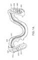
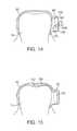
- FIG. 1Ashows a perspective top view of a bone conduction hearing appliance.
- FIG. 1Bshows a perspective side view of the appliance of FIG. 1A .
- FIG. 1Cshows an exemplary mechanical placement of components of each chamber of FIG. 1A .
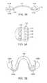
- FIG. 2Ashows a perspective view of a second embodiment of a hearing appliance.
- FIG. 2Bshows a cross-sectional rear view of the embodiment of FIG. 2A .
- FIG. 3Ashows a perspective view of a third embodiment of a hearing appliance.
- FIG. 3Bshows a top view of a fourth embodiment of a hearing appliance.
- FIG. 4shows a diagram illustrating the coupling of the actuator to one or more teeth.
- FIG. 5shows an equivalent model of the coupling of the actuator to the teeth.
- FIG. 6shows another embodiment to couple the actuator to a tooth.
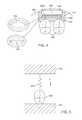
- FIG. 7Ashows an illustrative configuration of the individual components in a variation of the oral appliance device having an external transmitting assembly with a receiving and transducer assembly within the mouth.
- FIG. 7Bshows an illustrative configuration of another variation of the device in which the entire assembly is contained by the oral appliance within the user's mouth.
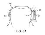
- FIG. 8Ashows a partial cross-sectional view of another variation of an oral appliance placed upon a tooth with an electronics/transducer assembly pressed against the tooth surface via an osmotic pouch.
- FIG. 8Bshows a partial cross-sectional view of another variation of an oral appliance placed upon a tooth with an electronics/transducer assembly pressed against the tooth surface via one or more biasing elements.
- FIG. 9illustrates another variation of an oral appliance having an electronics assembly and a transducer assembly separated from one another within the electronics and transducer housing of the oral appliance.
- FIGS. 10 and 11illustrate additional variations of oral appliances in which the electronics and transducer assembly are maintainable against the tooth surface via a ramped surface and a biasing element.
- FIG. 12shows yet another variation of an oral appliance having an interfacing member positioned between the electronics and/or transducer assembly and the tooth surface.
- FIG. 13shows yet another variation of an oral appliance having an actuatable mechanism for urging the electronics and/or transducer assembly against the tooth surface.
- FIG. 14shows yet another variation of an oral appliance having a cam mechanism for urging the electronics and/or transducer assembly against the tooth surface.
- FIG. 15shows yet another variation of an oral appliance having a separate transducer mechanism positionable upon the occlusal surface of the tooth for transmitting vibrations.
- FIG. 16illustrates another variation of an oral appliance having a mechanism for urging the electronics and/or transducer assembly against the tooth surface utilizing a bite-actuated mechanism.
- FIG. 17shows yet another variation of an oral appliance having a composite dental anchor for coupling the transducer to the tooth.
- FIGS. 18A and 18Bshow side and top views, respectively, of an oral appliance variation having one or more transducers which may be positioned over the occlusal surface of the tooth.
- FIGS. 19A and 19Billustrate yet another variation of an oral appliance made from a shape memory material in its pre-formed relaxed configuration and its deformed configuration when placed over or upon the patient's tooth, respectively, to create an interference fit.
- FIG. 20illustrates yet another variation of an oral appliance made from a pre-formed material in which the transducer may be positioned between the biased side of the oral appliance and the tooth surface.
- FIG. 21illustrates a variation in which the oral appliance may be omitted and the electronics and/or transducer assembly may be attached to a composite dental anchor attached directly to the tooth surface.
- FIGS. 22A and 22Bshow partial cross-sectional side and perspective views, respectively, of another variation of an oral appliance assembly having its occlusal surface removed or omitted for patient comfort.
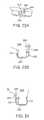
- FIGS. 23A and 23Billustrate perspective and side views, respectively, of an oral appliance which may be coupled to a screw or post implanted directly into the underlying bone, such as the maxillary or mandibular bone.
- FIG. 24illustrates another variation in which the oral appliance may be coupled to a screw or post implanted directly into the palate of a patient.
- FIGS. 25A and 25Billustrate perspective and side views, respectively, of an oral appliance which may have its transducer assembly or a coupling member attached to the gingival surface to conduct vibrations through the gingival tissue and underlying bone.
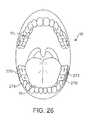
- FIG. 26illustrates an example of how multiple oral appliance two-way communication assemblies or transducers may be placed on multiple teeth throughout the patient's mouth.
- FIGS. 27A and 27Billustrate perspective and side views, respectively, of an oral appliance (similar to a variation shown above) which may have a microphone unit positioned adjacent to or upon the gingival surface to physically separate the microphone from the transducer to attenuate or eliminate feedback.
- FIG. 28illustrates another variation of a removable oral appliance supported by an arch and having a microphone unit integrated within the arch.
- FIG. 29shows yet another variation illustrating at least one microphone and optionally additional microphone units positioned around the user's mouth and in wireless communication with the electronics and/or transducer assembly.
- FIG. 1AAn exemplary removable wireless dental hearing appliance is shown in FIG. 1A .
- the applianceis worn by a user in his or her oral cavity.
- the applianceincludes a power chamber 401 that supplies energy to power the appliance.
- the power chamber 401includes an energy reservoir 402 such as a battery.
- the batteryis charged by charger electronic 403 which can receive external energy through inductive coupling or can directly receive a charge through two terminals. If the charging is to be done inductively, a recharging coil 404 is also enclosed in the power chamber 401 .
- the power chamber 401provides energy for electronics in an actuation chamber 407 .
- the chambers 401 and 407are connected by a bridge 405 .
- Inside the bridge 405are cables that supply power to the actuation chamber 407 .
- Other devicessuch as antenna wires can be embedded in the bridge 405 .
- the chambers 401 , 407 and the bridge 405are made from human compatible elastomeric materials commonly used in dental retainers, among others.
- an actuator 408is positioned near the patient's teeth.
- the actuator 408is driven by an electronic driver 409 .
- a wireless transceiver 450provides sound information to the electronic driver 409 so that the driver 409 can actuate the actuator 408 to cause sound to be generated and conducted to the patient's ear through bone conduction in one embodiment.
- the electronic and actuator assemblymay receive incoming sounds either directly or through a receiver to process and amplify the signals and transmit the processed sounds via a vibrating transducer element coupled to a tooth or other bone structure, such as the maxillary, mandibular, or palatine bone structure.
- Other sound transmission techniques in addition to bone conductioncan be used and are contemplated by the inventors.
- FIG. 1Bshows a side perspective view of the appliance of FIG. 1A .
- the oral appliance of FIG. 1Amay be a custom-made device fabricated through a variety of different process utilizing, e.g., a replicate model of a dental structure obtained by any number of methods, as described below in further detail.
- the oral appliancemay accordingly be created to fit, adhere, or be otherwise disposed upon a portion of the patient's dentition to maintain the electronics and transducer device against the patient's dentition securely and comfortably.
- FIG. 1Cshows a perspective view of the electronics housed by the chambers 401 and 407 .
- the recharging coil 404is positioned at one end and the battery 402 is positioned at the other end of the chamber 401 .
- the control electronics for the charging operationis in a circuit board 420 B behind the battery 402 and coil 404 .
- the actuator 408in turn is made up of a piezoelectric actuator 408 B that moves a mass 408 A.
- the driver 409 and wireless transceiver circuitryare provided on a circuit board 420 A.
- FIG. 2Ashows a second embodiment where the bridge as well as the mechanical supports for the chambers are made from metallic wire frames.
- chambers 411 and 417are supported by wire frames 413 A and 413 B, respectively.
- the support wire frames 413 A- 413 Bare mechanically secured to a main wire frame 415 .
- the cabling for electrical communication between chambers 411 and 417can be made through wires running along the outside of the wireframes.
- FIG. 2Bshows one embodiment of FIG. 2A where the main wire frame 415 is hollow to allow wire cabling to run inside the main wire frame 415 .
- the wire assemblycan be soldered or otherwise connected to electrical contacts on the chambers 411 or 417 as needed to connect circuits between chambers 411 and 417 .
- FIG. 3Ashows a third embodiment where the power supply, transceiver, and actuator are housed in a single chamber 430 .
- the chamber 430is mounted intra-orally to one or more teeth.
- An actuator 432is positioned adjacent the teeth.
- the actuator 432can include a mass and a piezoelectric transducer as discussed above.
- a battery 434provides power for the whole system and the battery 434 can be recharged through a charger 436 .
- the actuator 432is driven by an amplifier 438 , which receives audio input from a transceiver 440 .
- the transceiver 440contains an antenna to capture wireless signals transmitted by a remote audio device.
- a microphonecan provide sound input that is amplified by the amplifier or driver 438 .
- the systemcan receive signals from a linking unit such as a Bluetooth transceiver that allows the appliance to play sound generated by a portable appliance or a sound source such as a music player, a hands-free communication device or a cellular telephone, for example.
- the sound sourcecan be a computer, a one-way communication device, a two-way communication device, or a wireless hands-free communication device
- FIG. 3Bshows a top view of a fourth embodiment of a hearing appliance.
- the appliancehas a body portion 442 that supports two chambers 446 A- 446 B that house the actuator, transceiver, control electronic, and power supply, among others and allows for communication between the two.
- Two substantially C-shaped support wires 444 A and 444 Benable the appliance to clip onto the wearer's dental arch around curved regions 448 and to be secured therein.
- the C-shaped wire 444 A or 444 Bprovides a spring force to the actuator to keep it secured to the teeth.
- the wire materialcan be stainless steel or Nitinol, among others.
- FIG. 4shows an exemplary cross-sectional view showing the coupling of the sound transducer to one or more teeth 450 .
- a mounting unit 452such as a retainer-like housing is placed over one or more teeth 450 .
- the mounting unit 452can also be adhesive or glue or a suitable system to secure the appliance to the teeth 450 .
- An actuator 454rests above support arms or links 452 A and 452 B which are mechanically connected to the teeth 450 .
- the actuator 454is a piezoelectric transducer made with PZT.
- PZT-based compoundsPb[ZrxTi1 ⁇ x]O3 0 ⁇ x ⁇ 1, also lead zirconium titanate) are ceramic perovskite materials that develop a voltage difference across two of its facets when highly compressed. Being piezoelectric, it develops a voltage difference across two of its faces when compressed (useful for sensor applications), or physically changes shape when an external electric field is applied (useful for actuators and the like).
- the materialis also ferroelectric, which means it has a spontaneous electric polarization (electric dipole) which can be reversed in the presence of an electric field.
- the actuator 454is also connected to a mass 458 through a mass arm 456 .
- the actuator 454uses PZT in a rectangular beam bender configuration.
- the mass 458can be a tungsten material or any suitable weight such as the battery or control electronics, among others.
- the support arms or links 452 A- 452 B as well as the mass arm 456are preferably made from ceramic or alumina which enables acoustic or sound energy to be efficiently transmitted by the mounting unit 454 .
- the actuator 454can be commanded to contract or expand, resulting in movements with upward arch shapes or downward arch shapes.
- the actuator 454 and its associated componentsare encapsulated in a compressible material 460 such as silicone to allow actuator movement.
- the top of the applianceis provided with an acrylic encapsulated protection layer 462 providing a fixed platform that directs energy generated by the actuator 454 toward the teeth while the compressible material 460 provides room for movement by the actuator 454 .
- FIG. 5shows a schematic equivalent of the system of FIG. 4 .
- a tooth 450is fixed between bone structure 451 and a mounting unit 455 such as a retainer, both of which are spatially fixed in the model.
- An actuator 453provides resistance to drive energy into the tooth 450 .
- FIG. 5shows two fixed point connections, it is contemplated that the actuator 452 can have one fixed point connection as well. This resistance between the tooth and the retainer applies the coupling force necessary to keep the actuator in contact with the tooth at high frequencies.
- FIG. 6shows an exemplary embodiment to mount an actuator or transducer.
- a base 472is secured to a tooth 470 .
- the basehas a clip type housing with an top arm 476 and two bottom contacts 474 that together resiliently urge a mass 478 toward the top arm 476 .
- a rod 480is positioned on the base 472 with one or more pins to hold the mass 478 in position similar to a spring that biases the mass 478 against the arm 476 to provide a better contact or coupling between the mass and the tooth 470 through the base 472 .
- the appliancecan be a custom oral device.
- the sound source unitcan contain a short-range transceiver that is protocol compatible with the linking unit.
- the sound sourcecan have a Bluetooth transceiver that communicates with the Bluetooth transceiver linking unit in the appliance.
- the appliancecan then receive the data transmitted over the Bluetooth protocol and drive a bone conduction transducer to render or transmit sound to the user.
- the appliancecan have a microphone embedded therein.
- the microphonecan be an intraoral microphone or an extraoral microphone.
- a second microphonecan be used to cancel environmental noise and transmit a user's voice to the telephone.
- a noise cancellerreceives signals from the microphones and cancels ambient noise to provide a clean sound capture.
- the appliancecan have another microphone to pick up ambient sound.
- the microphonecan be an intraoral microphone or an extraoral microphone.
- the microphonecancels environmental noise and transmits a user's voice to the remote station. This embodiment provides the ability to cancel environmental noises while transmitting subject's own voice to the actuator 432 .
- the systemcan handle environmental noise reduction that is important in working in high noise areas.
- the systemcouples microphones and voicing activity sensors to a signal processor.
- the processorexecutes a detection algorithm, and a denoising code to minimize background acoustic noise.
- Two microphonescan be used, with one microphone being the bone conduction microphone and one which is considered the “signal” microphone.
- the second microphonecaptures air noise or ambient noise, whose signal is filtered and subtracted from the signal in the first microphone.
- the systemruns an array algorithm for speech detection that uses the difference in frequency content between two microphones to calculate a relationship between the signals of the two microphones. As known in the art and discussed in U.S. Pat. No. 7,246,058, the content of which is incorporated by reference, this embodiment can cancel noise without requiring a specific orientation of the array with respect to the signal.
- the appliancecan be attached, adhered, or otherwise embedded into or upon a removable oral appliance or other oral device to form a medical tag containing patient identifiable information.
- a removable oral appliance or other oral devicemay be a custom-made device fabricated from a thermal forming process utilizing a replicate model of a dental structure obtained by conventional dental impression methods.
- the electronic and transducer assemblymay receive incoming sounds either directly or through a receiver to process and amplify the signals and transmit the processed sounds via a vibrating transducer element coupled to a tooth or other bone structure, such as the maxillary, mandibular, or palatine bone structure.
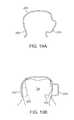
- microphonescan be place on each side of the ears to provide noise cancellation, optimal sound localization and directionality.
- the microphonescan be placed inside or outside the ears.
- the microphonescan be placed either at the opening or directly with the user's ear canals.
- Each of the systemsincludes a battery, a signal processor, a transmitter, all of which can be positioned in a housing that clips onto the ear which, rests behind the ear between the pinna and the skull, or alternatively can be positioned in the ear's concha.
- the transmitteris connected to a wire/antenna that in turn is connected to the microphone.
- Each transmittertransmits information to a receiver that activates a transducer that is powered by a battery.
- Each side of the headcan have one set of receiver, transducer and battery.
- This embodimentprovides a bone conduction hearing aid device with dual externally located microphones that are placed at the entrance to or in the ear canals and an oral appliance containing dual transducers in communication with each other. The device will allow the user to enjoy the most natural sound input due to the location of the microphone which takes advantage of the pinna for optimal sound localization (and directionality).
- the microphonesreceive sound signals from both sides of the head, processes those signals to send a signal to the transducer on the side of the head where the sound is perceived by the microphone to be at a higher sound level.
- a phase-shifted signalis sent to the transducer on the opposite side of the head.
- the microphone at the first earreceives sound signals from the first side of the head, processes those signal to send a signal to the transducer on that same or first side of the oral appliance.
- a second microphone at the second earreceives a sound signal that is lower in amplitude and delayed in respect to the sound sensed by the first microphone due to head shadowing and physical separation of the microphones, and sends a corresponding signal to the second transducer on the second side of the oral appliance.
- the sound signals from the transducerswill be perceived by each cochlea on each side of the head as being different in amplitude and phase, which will result in the perception of directionality by the user.
- components such as the battery, the signal processor, and the transmittercan either be located behind the ear or within the folds of the pinna.
- the human auricleis an almost rudimentary, usually immobile shell that lies close to the side of the head with a thin plate of yellow fibrocartilage covered by closely adherent skin.
- the cartilageis molded into clearly defined hollows, ridges, and furrows that form an irregular, shallow funnel.
- the deepest depression, which leads directly to the external auditory canal, or acoustic meatus,is called the concha. It is partly covered by two small projections, the tonguelike tragus in front and the antitragus behind.
- the helixarises from the floor of the concha and continues as the incurved rim of the upper portion of the auricle.
- An inner, concentric ridge, the antihelixsurrounds the concha and is separated from the helix by a furrow, the scapha, also called the fossa of the helix.
- the lobulethe fleshy lower part of the auricle, is the only area of the outer ear that contains no cartilage.
- the auriclealso has several small rudimentary muscles, which fasten it to the skull and scalp. In most individuals these muscles do not function, although some persons can voluntarily activate them to produce limited movements.
- the external auditory canalis a slightly curved tube that extends inward from the floor of the concha and ends blindly at the tympanic membrane.
- the wall of the canalconsists of cartilage; in its inner two-thirds, of bone.
- the anthelix (antihelix)is a folded “Y” shaped part of the ear.
- the antitragusis the lower cartilaginous edge of the conchal bowl just above the fleshy lobule of the ear.
- the microphoneis connected with the transmitter through the wire and antenna.
- the placement of the microphone inside the ear canalprovides the user with the most natural sound input due to the location of the microphone which takes advantage of the pinna for optimal sound localization (and directionality) when the sounds are transmitted to the cochlea using a straight signal and “phase-shifted” signal to apply directionality to the patient.
- High quality sound inputis captured by placing the microphones within or at the entrance of the ear canal which would allow the patient to use the sound reflectivity of the pinna as well as improved sound directionality due to the microphone placement.
- the arrangementavoids the need to separate the microphone and speaker to reduce the chance of feedback and allows placement of the microphone to take advantage of the sound reflectivity of the pinna.
- the systemalso allows for better sound directionality due to the two bone conduction transducers being in electrical contact with each other. With the processing of the signals prior to being sent to the transducers and the transducers able to communicate with each other, the system provides the best sound localization possible.
- the appliancecan include a data storage device such as a solid state memory or a flash storage device.
- the content of the data storage devicecan be encrypted for security.
- the linking unitcan transmit encrypted data for secure transmission if desired.
- the appliancemay be fabricated from various polymeric or a combination of polymeric and metallic materials using any number of methods, such as computer-aided machining processes using computer numerical control (CNC) systems or three-dimensional printing processes, e.g., stereolithography apparatus (SLA), selective laser sintering (SLS), and/or other similar processes utilizing three-dimensional geometry of the patient's dentition, which may be obtained via any number of techniques.
- CNCcomputer numerical control
- SLAstereolithography apparatus
- SLSselective laser sintering
- Such techniquesmay include use of scanned dentition using intra-oral scanners such as laser, white light, ultrasound, mechanical three-dimensional touch scanners, magnetic resonance imaging (MRI), computed tomography (CT), other optical methods, etc.
- the appliancemay be optionally formed such that it is molded to fit over the dentition and at least a portion of the adjacent gingival tissue to inhibit the entry of food, fluids, and other debris into the oral appliance and between the transducer assembly and tooth surface. Moreover, the greater surface area of the oral appliance may facilitate the placement and configuration of the assembly onto the appliance.
- the removable oral appliancemay be optionally fabricated to have a shrinkage factor such that when placed onto the dentition, oral appliance may be configured to securely grab onto the tooth or teeth as the appliance may have a resulting size slightly smaller than the scanned tooth or teeth upon which the appliance was formed. The fitting may result in a secure interference fit between the appliance and underlying dentition.
- an extra-buccal transmitter assembly located outside the patient's mouthmay be utilized to receive auditory signals for processing and transmission via a wireless signal to the electronics and/or transducer assembly positioned within the patient's mouth, which may then process and transmit the processed auditory signals via vibratory conductance to the underlying tooth and consequently to the patient's inner ear.
- the transmitter assemblymay contain a microphone assembly as well as a transmitter assembly and may be configured in any number of shapes and forms worn by the user, such as a watch, necklace, lapel, phone, belt-mounted device, etc.
- FIG. 7Aillustrates a schematic representation of one variation of two-way communication assembly 14 utilizing an extra-buccal transmitter assembly 22 , which may generally comprise microphone 30 for receiving sounds and which is electrically connected to processor 32 for processing the auditory signals.
- Processor 32may be connected electrically to transmitter 34 for transmitting the processed signals to the electronics and/or transducer assembly 16 disposed upon or adjacent to the user's teeth.
- the microphone 30 and processor 32may be configured to detect and process auditory signals in any practicable range, but may be configured in one variation to detect auditory signals ranging from, e.g., 250 Hertz to 20,000 Hertz.
- microphone 30may be a digital, analog, and/or directional type microphone. Such various types of microphones may be interchangeably configured to be utilized with the assembly, if so desired.
- Power supply 36may be connected to each of the components in transmitter assembly 22 to provide power thereto.
- the transmitter signals 24may be in any wireless form utilizing, e.g., radio frequency, ultrasound, microwave, Blue Tooth® (BLUETOOTH SIG, INC., Bellevue, Wash.), etc. for transmission to assembly 16 .
- Assembly 22may also optionally include one or more input controls 28 that a user may manipulate to adjust various acoustic parameters of the electronics and/or transducer assembly 16 , such as acoustic focusing, volume control, filtration, muting, frequency optimization, sound adjustments, and tone adjustments, etc.
- the signals transmitted 24 by transmitter 34may be received by electronics and/or transducer assembly 16 via receiver 38 , which may be connected to an internal processor for additional processing of the received signals.
- the received signalsmay be communicated to transducer 40 , which may vibrate correspondingly against a surface of the tooth to conduct the vibratory signals through the tooth and bone and subsequently to the middle ear to facilitate hearing of the user.
- Transducer 40may be configured as any number of different vibratory mechanisms.
- transducer 40may be an electromagnetically actuated transducer.
- transducer 40may be in the form of a piezoelectric crystal having a range of vibratory frequencies, e.g., between 250 to 4000 Hz.
- Power supply 42may also be included with assembly 16 to provide power to the receiver, transducer, and/or processor, if also included.
- power supply 42may be a simple battery, replaceable or permanent
- other variationsmay include a power supply 42 which is charged by inductance via an external charger.
- power supply 42may alternatively be charged via direct coupling to an alternating current (AC) or direct current (DC) source.
- ACalternating current
- DCdirect current
- Other variationsmay include a power supply 42 which is charged via a mechanical mechanism, such as an internal pendulum or slidable electrical inductance charger as known in the art, which is actuated via, e.g., motions of the jaw and/or movement for translating the mechanical motion into stored electrical energy for charging power supply 42 .
- two-way communication assembly 50may be configured as an independent assembly contained entirely within the user's mouth, as shown in FIG. 5 .
- assembly 50may include an internal microphone 52 in communication with an on-board processor 54 .
- Internal microphone 52may comprise any number of different types of microphones, as described above.
- Processor 54may be used to process any received auditory signals for filtering and/or amplifying the signals and transmitting them to transducer 56 , which is in vibratory contact against the tooth surface.
- Power supply 58as described above, may also be included within assembly 50 for providing power to each of the components of assembly 50 as necessary.
- an osmotic patch or expandable hydrogel 74may be placed between housing 62 and electronics and/or transducer assembly 72 .
- hydrogel 74may absorb some fluids, either from any surrounding fluid or from a fluid introduced into hydrogel 74 , such that hydrogel 74 expands in size to force assembly 72 into contact against the tooth surface.
- Assembly 72may be configured to define a contact surface 70 having a relatively smaller contact area to facilitate uniform contact of the surface 70 against the tooth.
- a contact surface 70may be included in any of the variations described herein.
- a thin encapsulating layer or surface 76may be placed over housing 62 between contact surface 70 and the underlying tooth to prevent any debris or additional fluids from entering housing 62 .
- FIG. 8Bshows electronics and/or transducer assembly 80 contained within housing 62 .
- one or more biasing elements 82e.g., springs, pre-formed shape memory elements, etc., may be placed between assembly 80 and housing 62 to provide a pressing force on assembly 80 to urge the device against the underlying tooth surface, thereby ensuring mechanical contact.
- the electronicsmay be contained as a separate assembly 90 which is encapsulated within housing 62 and the transducer 92 may be maintained separately from assembly 90 but also within housing 62 .
- transducer 92may be urged against the tooth surface via a spring or other biasing element 94 and actuated via any of the mechanisms described above.
- electronics and/or transducer assembly 100may be configured to have a ramped surface 102 in apposition to the tooth surface.
- the surface 102may be angled away from the occlusal surface of the tooth.
- the assembly 100may be urged via a biasing element or spring 106 which forces the ramped surface 102 to pivot about a location 104 into contact against the tooth to ensure contact for the transducer against the tooth surface.
- FIG. 11illustrates another similar variation in electronics and/or transducer assembly 110 also having a ramped surface 112 in apposition to the tooth surface.
- the ramped surface 112may be angled towards the occlusal surface of the tooth.
- assembly 110may be urged via a biasing element or spring 116 which urges the assembly 110 to pivot about its lower end such that the assembly 110 contacts the tooth surface at a region 114 .
- electronics and/or transducer assembly 120may be positioned within housing 62 with an interface layer 122 positioned between the assembly 120 and the tooth surface.
- Interface layer 122may be configured to conform against the tooth surface and against assembly 120 such that vibrations may be transmitted through layer 122 and to the tooth in a uniform manner. Accordingly, interface layer 122 may be made from a material which attenuates vibrations minimally. Interface layer 122 may be made in a variety of forms, such as a simple insert, an O-ring configuration, etc. or even in a gel or paste form, such as denture or oral paste, etc. Additionally, layer 122 may be fabricated from various materials, e.g., hard plastics or polymeric materials, metals, etc.
- FIG. 13illustrates yet another variation in which electronics and/or transducer assembly 130 may be urged against the tooth surface via a mechanical mechanism.
- assembly 130may be attached to a structural member 132 , e.g., a threaded member or a simple shaft, which is connected through housing 62 to an engagement member 134 located outside housing 62 .
- the usermay rotate engagement member 134 (as indicated by rotational arrow 136 ) or simply push upon member 134 (as indicated by linear arrow 138 ) to urge assembly 130 into contact against the tooth.
- actuation of engagement member 134may be accomplished manually within the mouth or through the user's cheek or even through manipulation via the user's tongue against engagement member 134 .
- electronics and/or transducer assembly 140may define a portion as an engaging surface 142 for contacting against a cam or lever mechanism 144 .
- Cam or lever mechanism 144may be configured to pivot 146 such that actuation of a lever 148 extending through housing 62 may urge cam or lever mechanism 144 to push against engaging surface 142 such that assembly 140 is pressed against the underlying tooth surface.
- the electronics 150 and the transducer 152may be separated from one another such that electronics 150 remain disposed within housing 62 but transducer 152 , connected via wire 154 , is located beneath dental oral appliance 60 along an occlusal surface of the tooth, as shown in FIG. 15 .
- vibrationsare transmitted via the transducer 152 through the occlusal surface of the tooth.
- the usermay bite down upon the oral appliance 60 and transducer 152 to mechanically compress the transducer 152 against the occlusal surface to further enhance the mechanical contact between the transducer 152 and underlying tooth to further facilitate transmission therethrough.
- FIG. 16another example for a bite-enhanced coupling mechanism is illustrated where electronics and/or transducer assembly 160 defines an angled interface surface 162 in apposition to a correspondingly angled engaging member 164 .
- a proximal end of engaging member 164may extend through housing 62 and terminate in a pusher member 166 positioned over an occlusal surface of the tooth TH.
- an electronics and/or transducer assembly 170may define a channel or groove 172 along a surface for engaging a corresponding dental anchor 174 , as shown in FIG. 17 .
- Dental anchor 174may comprise a light-curable acrylate-based composite material adhered directly to the tooth surface.
- dental anchor 174may be configured in a shape which corresponds to a shape of channel or groove 172 such that the two may be interfitted in a mating engagement. In this manner, the transducer in assembly 170 may vibrate directly against dental anchor 174 which may then transmit these signals directly into the tooth TH.
- FIGS. 18A and 18Bshow partial cross-sectional side and top views, respectively, of another variation in which oral appliance 180 may define a number of channels or grooves 184 along a top portion of oral appliance 180 .
- one or more transducers 182 , 186 , 188 , 190may be disposed such that they are in contact with the occlusal surface of the tooth and each of these transducers may be tuned to transmit frequencies uniformly.
- each of these transducersmay be tuned to transmit only at specified frequency ranges.
- each transducercan be programmed or preset for a different frequency response such that each transducer may be optimized for a different frequency response and/or transmission to deliver a relatively high-fidelity sound to the user.
- FIGS. 19A and 19Billustrate an oral appliance 200 which may be pre-formed from a shape memory polymer or alloy or a superelastic material such as a Nickel-Titanium alloy, e.g., Nitinol.
- FIG. 19Ashows oral appliance 200 in a first configuration where members 202 , 204 are in an unbiased memory configuration.
- members 202 , 204When placed upon or against the tooth TH, members 202 , 204 may be deflected into a second configuration where members 202 ′, 204 ′ are deformed to engage tooth TH in a secure interference fit, as shown in FIG. 19B .
- the biased member 204 ′may be utilized to press the electronics and/or transducer assembly contained therein against the tooth surface as well as to maintain securement of the oral appliance 200 upon the tooth TH.
- removable oral appliance 210may have biased members to secure engage the tooth TH, as above.
- the ends of the members 212 , 214may be configured into curved portions under which a transducer element 218 coupled to electronics assembly 216 may be wedged or otherwise secured to ensure mechanical contact against the tooth surface.
- FIG. 21shows yet another variation in which the oral appliance is omitted entirely.
- a composite dental anchor or bracket 226as described above, may be adhered directly onto the tooth surface.
- bracket 226may be comprised of a biocompatible material, e.g., stainless steel, Nickel-Titanium, Nickel, ceramics, composites, etc., formed into a bracket and anchored onto the tooth surface.
- the bracket 226may be configured to have a shape 228 over which an electronics and/or transducer assembly 220 may be slid over or upon via a channel 222 having a corresponding receiving configuration 224 for engagement with bracket 226 .
- assembly 220may be directly engaged against bracket 226 , through which a transducer may directly vibrate into the underlying tooth TH. Additionally, in the event that assembly 220 is removed from the tooth TH, assembly 220 may be simply slid or rotated off bracket 226 and a replacement assembly may be put in its place upon bracket 226 .
- FIGS. 22A and 22Bshow partial cross-sectional side and perspective views, respectively, of yet another variation of an oral appliance 230 .
- the oral appliance 230may be configured to omit an occlusal surface portion of the oral appliance 230 and instead engages the side surfaces of the tooth TH, such as the lingual and buccal surfaces only.
- the electronics and/or transducer assembly 234may be contained, as above, within a housing 232 for contact against the tooth surface.
- one or more optional cross-members 236may connect the side portions of the oral appliance 230 to provide some structural stability when placed upon the tooth.
- This variationmay define an occlusal surface opening 238 such that when placed upon the tooth, the user may freely bite down directly upon the natural occlusal surface of the tooth unobstructed by the oral appliance device, thereby providing for enhanced comfort to the user.
- vibrationsmay be transmitted directly into the underlying bone or tissue structures rather than transmitting directly through the tooth or teeth of the user.
- an oral appliance 240is illustrated positioned upon the user's tooth, in this example upon a molar located along the upper row of teeth.
- the electronics and/or transducer assembly 242is shown as being located along the buccal surface of the tooth.
- a conduction transmission member 244such as a rigid or solid metallic member, may be coupled to the transducer in assembly 242 and extend from oral appliance 240 to a post or screw 246 which is implanted directly into the underlying bone 248 , such as the maxillary bone, as shown in the partial cross-sectional view of FIG. 23B .
- the vibrations generated by the transducermay be transmitted through transmission member 244 and directly into post or screw 246 , which in turn transmits the vibrations directly into and through the bone 248 for transmission to the user's inner ear.
- FIG. 24illustrates a partial cross-sectional view of an oral appliance 250 placed upon the user's tooth TH with the electronics and/or transducer assembly 252 located along the lingual surface of the tooth.
- the vibrationsmay be transmitted through the conduction transmission member 244 and directly into post or screw 246 , which in this example is implanted into the palatine bone PL.
- post or screw 246which in this example is implanted into the palatine bone PL.
- Other variationsmay utilize this arrangement located along the lower row of teeth for transmission to a post or screw 246 drilled into the mandibular bone.
- a transducermay be attached, coupled, or otherwise adhered directly to the gingival tissue surface adjacent to the teeth.
- an oral appliance 260may have an electronics assembly 262 positioned along its side with an electrical wire 264 extending therefrom to a transducer assembly 266 attached to the gingival tissue surface 268 next to the tooth TH.
- Transducer assembly 266may be attached to the tissue surface 268 via an adhesive, structural support arm extending from oral appliance 260 , a dental screw or post, or any other structural mechanism. In use, the transducer may vibrate and transmit directly into the underlying gingival tissue, which may conduct the signals to the underlying bone.
- FIG. 26illustrates one example where multiple transducer assemblies 270 , 272 , 274 , 276 may be placed on multiple teeth. Although shown on the lower row of teeth, multiple assemblies may alternatively be positioned and located along the upper row of teeth or both rows as well. Moreover, each of the assemblies may be configured to transmit vibrations within a uniform frequency range. Alternatively in other variations, different assemblies may be configured to vibrate within non-overlapping frequency ranges between each assembly.
- each transducer 270 , 272 , 274 , 276can be programmed or preset for a different frequency response such that each transducer may be optimized for a different frequency response and/or transmission to deliver a relatively high-fidelity sound to the user.
- each of the different transducers 270 , 272 , 274 , 276can also be programmed to vibrate in a manner which indicates the directionality of sound received by the microphone worn by the user.
- different transducers positioned at different locations within the user's mouthcan vibrate in a specified manner by providing sound or vibrational queues to inform the user which direction a sound was detected relative to an orientation of the user.
- a first transducer located, e.g., on a user's left toothcan be programmed to vibrate for sound detected originating from the user's left side.
- a second transducer located, e.g., on a user's right toothcan be programmed to vibrate for sound detected originating from the user's right side.
- Other variations and queuesmay be utilized as these examples are intended to be illustrative of potential variations.
- the microphonemay be integrated directly into the electronics and/or transducer assembly, as described above.
- the microphone unitmay be positioned at a distance from the transducer assemblies to minimize feedback.
- microphone unit 282may be separated from electronics and/or transducer assembly 280 , as shown in FIGS. 27A and 27B .
- the microphone unit 282 positioned upon or adjacent to the gingival surface 268may be electrically connected via wire(s) 264 .
- FIG. 28illustrates another variation 290 which utilizes an arch 19 connecting one or more tooth retaining portions 21 , 23 , as described above.
- the microphone unit 294may be integrated within or upon the arch 19 separated from the transducer assembly 292 .
- One or more wires 296 routed through arch 19may electrically connect the microphone unit 294 to the assembly 292 .
- microphone unit 294 and assembly 292may be wirelessly coupled to one another, as described above.
- FIG. 29illustrates another variation where at least one microphone 302 (or optionally any number of additional microphones 304 , 306 ) may be positioned within the mouth of the user while physically separated from the electronics and/or transducer assembly 300 .
- the one or optionally more microphones 302 , 304 , 306may be wirelessly coupled to the electronics and/or transducer assembly 300 in a manner which attenuates or eliminates feedback, if present, from the transducer.
Landscapes
- Health & Medical Sciences (AREA)
- Otolaryngology (AREA)
- General Health & Medical Sciences (AREA)
- Engineering & Computer Science (AREA)
- Acoustics & Sound (AREA)
- Neurosurgery (AREA)
- Physics & Mathematics (AREA)
- Signal Processing (AREA)
- Materials Engineering (AREA)
- Manufacturing & Machinery (AREA)
- Chemical & Material Sciences (AREA)
- Circuit For Audible Band Transducer (AREA)
- Telephone Set Structure (AREA)
- Dental Tools And Instruments Or Auxiliary Dental Instruments (AREA)
- Details Of Audible-Bandwidth Transducers (AREA)
Abstract
Description
Claims (21)
Priority Applications (2)
| Application Number | Priority Date | Filing Date | Title |
|---|---|---|---|
| US13/108,372US8433083B2 (en) | 2008-03-04 | 2011-05-16 | Dental bone conduction hearing appliance |
| US13/872,936US20130236043A1 (en) | 2008-03-04 | 2013-04-29 | Dental bone conduction hearing appliance |
Applications Claiming Priority (3)
| Application Number | Priority Date | Filing Date | Title |
|---|---|---|---|
| US12/042,186US20090226020A1 (en) | 2008-03-04 | 2008-03-04 | Dental bone conduction hearing appliance |
| US12/333,279US7945068B2 (en) | 2008-03-04 | 2008-12-11 | Dental bone conduction hearing appliance |
| US13/108,372US8433083B2 (en) | 2008-03-04 | 2011-05-16 | Dental bone conduction hearing appliance |
Related Parent Applications (1)
| Application Number | Title | Priority Date | Filing Date |
|---|---|---|---|
| US12/333,279ContinuationUS7945068B2 (en) | 2008-03-04 | 2008-12-11 | Dental bone conduction hearing appliance |
Related Child Applications (1)
| Application Number | Title | Priority Date | Filing Date |
|---|---|---|---|
| US13/872,936ContinuationUS20130236043A1 (en) | 2008-03-04 | 2013-04-29 | Dental bone conduction hearing appliance |
Publications (2)
| Publication Number | Publication Date |
|---|---|
| US20110280416A1 US20110280416A1 (en) | 2011-11-17 |
| US8433083B2true US8433083B2 (en) | 2013-04-30 |
Family
ID=41053619
Family Applications (4)
| Application Number | Title | Priority Date | Filing Date |
|---|---|---|---|
| US12/042,186AbandonedUS20090226020A1 (en) | 2008-03-04 | 2008-03-04 | Dental bone conduction hearing appliance |
| US12/333,279Active2028-10-18US7945068B2 (en) | 2008-03-04 | 2008-12-11 | Dental bone conduction hearing appliance |
| US13/108,372Expired - Fee RelatedUS8433083B2 (en) | 2008-03-04 | 2011-05-16 | Dental bone conduction hearing appliance |
| US13/872,936AbandonedUS20130236043A1 (en) | 2008-03-04 | 2013-04-29 | Dental bone conduction hearing appliance |
Family Applications Before (2)
| Application Number | Title | Priority Date | Filing Date |
|---|---|---|---|
| US12/042,186AbandonedUS20090226020A1 (en) | 2008-03-04 | 2008-03-04 | Dental bone conduction hearing appliance |
| US12/333,279Active2028-10-18US7945068B2 (en) | 2008-03-04 | 2008-12-11 | Dental bone conduction hearing appliance |
Family Applications After (1)
| Application Number | Title | Priority Date | Filing Date |
|---|---|---|---|
| US13/872,936AbandonedUS20130236043A1 (en) | 2008-03-04 | 2013-04-29 | Dental bone conduction hearing appliance |
Country Status (5)
| Country | Link |
|---|---|
| US (4) | US20090226020A1 (en) |
| EP (1) | EP2263387A4 (en) |
| CN (2) | CN105872927A (en) |
| HK (1) | HK1226233A1 (en) |
| WO (1) | WO2009111566A1 (en) |
Cited By (65)
| Publication number | Priority date | Publication date | Assignee | Title |
|---|---|---|---|---|
| US20110294420A1 (en)* | 2009-03-26 | 2011-12-01 | Alps Electric Co., Ltd. | Communication system |
| US9609423B2 (en) | 2013-09-27 | 2017-03-28 | Volt Analytics, Llc | Noise abatement system for dental procedures |
| US20190046297A1 (en)* | 2017-08-11 | 2019-02-14 | Align Technology, Inc. | Devices and systems for creation of attachments for use with dental appliances and changeable shaped attachments |
| US10348350B2 (en) | 2016-09-22 | 2019-07-09 | Sonitus Technologies, Inc. | Two-way communication system and method of use |
| US10390913B2 (en) | 2018-01-26 | 2019-08-27 | Align Technology, Inc. | Diagnostic intraoral scanning |
| US10412512B2 (en) | 2006-05-30 | 2019-09-10 | Soundmed, Llc | Methods and apparatus for processing audio signals |
| US10421152B2 (en) | 2011-09-21 | 2019-09-24 | Align Technology, Inc. | Laser cutting |
| US10449016B2 (en) | 2014-09-19 | 2019-10-22 | Align Technology, Inc. | Arch adjustment appliance |
| US10470847B2 (en) | 2016-06-17 | 2019-11-12 | Align Technology, Inc. | Intraoral appliances with sensing |
| US10484805B2 (en) | 2009-10-02 | 2019-11-19 | Soundmed, Llc | Intraoral appliance for sound transmission via bone conduction |
| US10504386B2 (en) | 2015-01-27 | 2019-12-10 | Align Technology, Inc. | Training method and system for oral-cavity-imaging-and-modeling equipment |
| US10509838B2 (en) | 2016-07-27 | 2019-12-17 | Align Technology, Inc. | Methods and apparatuses for forming a three-dimensional volumetric model of a subject's teeth |
| US10517482B2 (en) | 2017-07-27 | 2019-12-31 | Align Technology, Inc. | Optical coherence tomography for orthodontic aligners |
| US10524881B2 (en) | 2010-04-30 | 2020-01-07 | Align Technology, Inc. | Patterned dental positioning appliance |
| US10537405B2 (en) | 2014-11-13 | 2020-01-21 | Align Technology, Inc. | Dental appliance with cavity for an unerupted or erupting tooth |
| US10543064B2 (en) | 2008-05-23 | 2020-01-28 | Align Technology, Inc. | Dental implant positioning |
| US10548700B2 (en) | 2016-12-16 | 2020-02-04 | Align Technology, Inc. | Dental appliance etch template |
| US10595966B2 (en) | 2016-11-04 | 2020-03-24 | Align Technology, Inc. | Methods and apparatuses for dental images |
| US10610332B2 (en) | 2012-05-22 | 2020-04-07 | Align Technology, Inc. | Adjustment of tooth position in a virtual dental model |
| US10613515B2 (en) | 2017-03-31 | 2020-04-07 | Align Technology, Inc. | Orthodontic appliances including at least partially un-erupted teeth and method of forming them |
| WO2020076640A1 (en)* | 2018-10-08 | 2020-04-16 | Nanoear Corporation, Inc. | Compact hearing aids |
| US10639134B2 (en) | 2017-06-26 | 2020-05-05 | Align Technology, Inc. | Biosensor performance indicator for intraoral appliances |
| US10758321B2 (en) | 2008-05-23 | 2020-09-01 | Align Technology, Inc. | Smile designer |
| US10779718B2 (en) | 2017-02-13 | 2020-09-22 | Align Technology, Inc. | Cheek retractor and mobile device holder |
| US10813720B2 (en) | 2017-10-05 | 2020-10-27 | Align Technology, Inc. | Interproximal reduction templates |
| US10842601B2 (en) | 2008-06-12 | 2020-11-24 | Align Technology, Inc. | Dental appliance |
| US10885521B2 (en) | 2017-07-17 | 2021-01-05 | Align Technology, Inc. | Method and apparatuses for interactive ordering of dental aligners |
| US10893918B2 (en) | 2012-03-01 | 2021-01-19 | Align Technology, Inc. | Determining a dental treatment difficulty |
| US10919209B2 (en) | 2009-08-13 | 2021-02-16 | Align Technology, Inc. | Method of forming a dental appliance |
| US10980613B2 (en) | 2017-12-29 | 2021-04-20 | Align Technology, Inc. | Augmented reality enhancements for dental practitioners |
| US10993783B2 (en) | 2016-12-02 | 2021-05-04 | Align Technology, Inc. | Methods and apparatuses for customizing a rapid palatal expander |
| US11026831B2 (en) | 2016-12-02 | 2021-06-08 | Align Technology, Inc. | Dental appliance features for speech enhancement |
| US11026768B2 (en) | 1998-10-08 | 2021-06-08 | Align Technology, Inc. | Dental appliance reinforcement |
| US11045283B2 (en) | 2017-06-09 | 2021-06-29 | Align Technology, Inc. | Palatal expander with skeletal anchorage devices |
| US11083545B2 (en) | 2009-03-19 | 2021-08-10 | Align Technology, Inc. | Dental wire attachment |
| US11096763B2 (en) | 2017-11-01 | 2021-08-24 | Align Technology, Inc. | Automatic treatment planning |
| US11103330B2 (en) | 2015-12-09 | 2021-08-31 | Align Technology, Inc. | Dental attachment placement structure |
| US11116605B2 (en) | 2017-08-15 | 2021-09-14 | Align Technology, Inc. | Buccal corridor assessment and computation |
| US20210282651A1 (en)* | 2020-03-13 | 2021-09-16 | Seiko Holdings Kabushiki Kaisha | Intraoral sensing apparatus and manufacturing method thereof |
| US11123156B2 (en) | 2017-08-17 | 2021-09-21 | Align Technology, Inc. | Dental appliance compliance monitoring |
| US11213368B2 (en) | 2008-03-25 | 2022-01-04 | Align Technology, Inc. | Reconstruction of non-visible part of tooth |
| US11219506B2 (en) | 2017-11-30 | 2022-01-11 | Align Technology, Inc. | Sensors for monitoring oral appliances |
| US11223913B2 (en) | 2018-10-08 | 2022-01-11 | Nanoear Corporation, Inc. | Compact hearing aids |
| US11259131B2 (en) | 2019-06-06 | 2022-02-22 | Nanoear Corporation, Inc. | Hearing aid implant recharging system |
| US11273011B2 (en) | 2016-12-02 | 2022-03-15 | Align Technology, Inc. | Palatal expanders and methods of expanding a palate |
| US11376101B2 (en) | 2016-12-02 | 2022-07-05 | Align Technology, Inc. | Force control, stop mechanism, regulating structure of removable arch adjustment appliance |
| US11419702B2 (en) | 2017-07-21 | 2022-08-23 | Align Technology, Inc. | Palatal contour anchorage |
| US11426259B2 (en) | 2012-02-02 | 2022-08-30 | Align Technology, Inc. | Identifying forces on a tooth |
| US11432908B2 (en) | 2017-12-15 | 2022-09-06 | Align Technology, Inc. | Closed loop adaptive orthodontic treatment methods and apparatuses |
| US11471252B2 (en) | 2008-10-08 | 2022-10-18 | Align Technology, Inc. | Dental positioning appliance having mesh portion |
| US11534268B2 (en) | 2017-10-27 | 2022-12-27 | Align Technology, Inc. | Alternative bite adjustment structures |
| US11534974B2 (en) | 2017-11-17 | 2022-12-27 | Align Technology, Inc. | Customized fabrication of orthodontic retainers based on patient anatomy |
| US11554000B2 (en) | 2015-11-12 | 2023-01-17 | Align Technology, Inc. | Dental attachment formation structure |
| US11564777B2 (en) | 2018-04-11 | 2023-01-31 | Align Technology, Inc. | Releasable palatal expanders |
| US11576752B2 (en) | 2017-10-31 | 2023-02-14 | Align Technology, Inc. | Dental appliance having selective occlusal loading and controlled intercuspation |
| US11596502B2 (en) | 2015-12-09 | 2023-03-07 | Align Technology, Inc. | Dental attachment placement structure |
| US11612454B2 (en) | 2010-04-30 | 2023-03-28 | Align Technology, Inc. | Individualized orthodontic treatment index |
| US11612455B2 (en) | 2016-06-17 | 2023-03-28 | Align Technology, Inc. | Orthodontic appliance performance monitor |
| US11633268B2 (en) | 2017-07-27 | 2023-04-25 | Align Technology, Inc. | Tooth shading, transparency and glazing |
| US11638629B2 (en) | 2014-09-19 | 2023-05-02 | Align Technology, Inc. | Arch expanding appliance |
| US11931222B2 (en) | 2015-11-12 | 2024-03-19 | Align Technology, Inc. | Dental attachment formation structures |
| US11937991B2 (en) | 2018-03-27 | 2024-03-26 | Align Technology, Inc. | Dental attachment placement structure |
| US11996181B2 (en) | 2017-06-16 | 2024-05-28 | Align Technology, Inc. | Automatic detection of tooth type and eruption status |
| US12090020B2 (en) | 2017-03-27 | 2024-09-17 | Align Technology, Inc. | Apparatuses and methods assisting in dental therapies |
| US12171575B2 (en) | 2017-10-04 | 2024-12-24 | Align Technology, Inc. | Intraoral systems and methods for sampling soft-tissue |
Families Citing this family (78)
| Publication number | Priority date | Publication date | Assignee | Title |
|---|---|---|---|---|
| US8270638B2 (en) | 2007-05-29 | 2012-09-18 | Sonitus Medical, Inc. | Systems and methods to provide communication, positioning and monitoring of user status |
| US20100098269A1 (en)* | 2008-10-16 | 2010-04-22 | Sonitus Medical, Inc. | Systems and methods to provide communication, positioning and monitoring of user status |
| US20120235632A9 (en)* | 2007-08-20 | 2012-09-20 | Sonitus Medical, Inc. | Intra-oral charging systems and methods |
| US7682303B2 (en) | 2007-10-02 | 2010-03-23 | Sonitus Medical, Inc. | Methods and apparatus for transmitting vibrations |
| US8150075B2 (en) | 2008-03-04 | 2012-04-03 | Sonitus Medical, Inc. | Dental bone conduction hearing appliance |
| US20090226020A1 (en) | 2008-03-04 | 2009-09-10 | Sonitus Medical, Inc. | Dental bone conduction hearing appliance |
| US8295506B2 (en) | 2008-07-17 | 2012-10-23 | Sonitus Medical, Inc. | Systems and methods for intra-oral based communications |
| US20110007920A1 (en)* | 2009-07-13 | 2011-01-13 | Sonitus Medical, Inc. | Intra-oral brackets for transmitting vibrations |
| US8622885B2 (en) | 2010-02-19 | 2014-01-07 | Audiodontics, Llc | Methods and apparatus for aligning antennas of low-powered intra- and extra-oral electronic wireless devices |
| US8437492B2 (en)* | 2010-03-18 | 2013-05-07 | Personics Holdings, Inc. | Earpiece and method for forming an earpiece |
| US8376967B2 (en) | 2010-04-13 | 2013-02-19 | Audiodontics, Llc | System and method for measuring and recording skull vibration in situ |
| WO2012087345A1 (en)* | 2010-12-03 | 2012-06-28 | Forbes Rehab Services, Inc. | Audio output module for use in artificial voice systems |
| US9313306B2 (en) | 2010-12-27 | 2016-04-12 | Rohm Co., Ltd. | Mobile telephone cartilage conduction unit for making contact with the ear cartilage |
| KR101604521B1 (en) | 2010-12-27 | 2016-03-17 | 로무 가부시키가이샤 | Transmitter/receiver unit and receiver unit |
| JP5783352B2 (en) | 2011-02-25 | 2015-09-24 | 株式会社ファインウェル | Conversation system, conversation system ring, mobile phone ring, ring-type mobile phone, and voice listening method |
| US8908891B2 (en) | 2011-03-09 | 2014-12-09 | Audiodontics, Llc | Hearing aid apparatus and method |
| US10419861B2 (en) | 2011-05-24 | 2019-09-17 | Cochlear Limited | Convertibility of a bone conduction device |
| US9744000B2 (en) | 2011-09-15 | 2017-08-29 | Lanfried Ortho Technology, Llc | Intra-oral appliance and methods of using same |
| US9179228B2 (en)* | 2011-12-09 | 2015-11-03 | Sophono, Inc. | Systems devices, components and methods for providing acoustic isolation between microphones and transducers in bone conduction magnetic hearing aids |
| WO2019237727A1 (en) | 2018-06-15 | 2019-12-19 | 深圳市韶音科技有限公司 | Bone conduction speaker and earphone |
| US11463814B2 (en) | 2011-12-23 | 2022-10-04 | Shenzhen Shokz Co., Ltd. | Bone conduction speaker and compound vibration device thereof |
| US11363362B2 (en) | 2018-06-15 | 2022-06-14 | Shenzhen Shokz Co., Ltd. | Speaker device |
| TWI660618B (en) | 2012-01-20 | 2019-05-21 | 日商精良股份有限公司 | Mobile phone |
| US9044291B2 (en) | 2012-05-09 | 2015-06-02 | Plantronics, Inc. | Jaw powered electric generator |
| TWI724317B (en) | 2012-06-29 | 2021-04-11 | 日商精良股份有限公司 | Headphones and stereo headphones |
| US9049527B2 (en)* | 2012-08-28 | 2015-06-02 | Cochlear Limited | Removable attachment of a passive transcutaneous bone conduction device with limited skin deformation |
| CN108551507A (en) | 2013-08-23 | 2018-09-18 | 罗姆股份有限公司 | Exhalation/incoming call communication, receiver, earphone, business card, non-contact IC card, mobile phone and its application method |
| EP3062491B1 (en) | 2013-10-24 | 2019-02-20 | FINEWELL Co., Ltd. | Bracelet-type transmission/reception device and bracelet-type notification device |
| JP6551919B2 (en) | 2014-08-20 | 2019-07-31 | 株式会社ファインウェル | Watch system, watch detection device and watch notification device |
| CN107113481B (en) | 2014-12-18 | 2019-06-28 | 株式会社精好 | Cartilage conduction hearing device using electromagnetic vibration unit and electromagnetic vibration unit |
| EP3323567B1 (en) | 2015-07-15 | 2020-02-12 | FINEWELL Co., Ltd. | Robot and robot system |
| US9905088B2 (en) | 2015-08-29 | 2018-02-27 | Bragi GmbH | Responsive visual communication system and method |
| US9843853B2 (en) | 2015-08-29 | 2017-12-12 | Bragi GmbH | Power control for battery powered personal area network device system and method |
| US9972895B2 (en) | 2015-08-29 | 2018-05-15 | Bragi GmbH | Antenna for use in a wearable device |
| US9949008B2 (en) | 2015-08-29 | 2018-04-17 | Bragi GmbH | Reproduction of ambient environmental sound for acoustic transparency of ear canal device system and method |
| US9949013B2 (en) | 2015-08-29 | 2018-04-17 | Bragi GmbH | Near field gesture control system and method |
| JP6551929B2 (en) | 2015-09-16 | 2019-07-31 | 株式会社ファインウェル | Watch with earpiece function |
| US9980189B2 (en) | 2015-10-20 | 2018-05-22 | Bragi GmbH | Diversity bluetooth system and method |
| US10104458B2 (en) | 2015-10-20 | 2018-10-16 | Bragi GmbH | Enhanced biometric control systems for detection of emergency events system and method |
| US9939891B2 (en) | 2015-12-21 | 2018-04-10 | Bragi GmbH | Voice dictation systems using earpiece microphone system and method |
| US9980033B2 (en) | 2015-12-21 | 2018-05-22 | Bragi GmbH | Microphone natural speech capture voice dictation system and method |
| US10778824B2 (en) | 2016-01-19 | 2020-09-15 | Finewell Co., Ltd. | Pen-type handset |
| US10085091B2 (en) | 2016-02-09 | 2018-09-25 | Bragi GmbH | Ambient volume modification through environmental microphone feedback loop system and method |
| US10085082B2 (en) | 2016-03-11 | 2018-09-25 | Bragi GmbH | Earpiece with GPS receiver |
| US10045116B2 (en) | 2016-03-14 | 2018-08-07 | Bragi GmbH | Explosive sound pressure level active noise cancellation utilizing completely wireless earpieces system and method |
| US10052065B2 (en) | 2016-03-23 | 2018-08-21 | Bragi GmbH | Earpiece life monitor with capability of automatic notification system and method |
| US10015579B2 (en) | 2016-04-08 | 2018-07-03 | Bragi GmbH | Audio accelerometric feedback through bilateral ear worn device system and method |
| WO2017183003A1 (en) | 2016-04-22 | 2017-10-26 | Cochlear Limited | Microphone placement |
| US10013542B2 (en) | 2016-04-28 | 2018-07-03 | Bragi GmbH | Biometric interface system and method |
| US10201309B2 (en) | 2016-07-06 | 2019-02-12 | Bragi GmbH | Detection of physiological data using radar/lidar of wireless earpieces |
| US10045110B2 (en) | 2016-07-06 | 2018-08-07 | Bragi GmbH | Selective sound field environment processing system and method |
| US10507087B2 (en) | 2016-07-27 | 2019-12-17 | Align Technology, Inc. | Methods and apparatuses for forming a three-dimensional volumetric model of a subject's teeth |
| US10062373B2 (en) | 2016-11-03 | 2018-08-28 | Bragi GmbH | Selective audio isolation from body generated sound system and method |
| US10058282B2 (en) | 2016-11-04 | 2018-08-28 | Bragi GmbH | Manual operation assistance with earpiece with 3D sound cues |
| US10045117B2 (en) | 2016-11-04 | 2018-08-07 | Bragi GmbH | Earpiece with modified ambient environment over-ride function |
| US10045112B2 (en) | 2016-11-04 | 2018-08-07 | Bragi GmbH | Earpiece with added ambient environment |
| US10063957B2 (en) | 2016-11-04 | 2018-08-28 | Bragi GmbH | Earpiece with source selection within ambient environment |
| GB2557258B8 (en)* | 2016-12-02 | 2019-09-25 | Gdm Int Ltd | A system and method for an in- mouth communicator |
| USD830994S1 (en)* | 2016-12-23 | 2018-10-16 | Samsung Electronics Co., Ltd. | Neckband earphone |
| USD845270S1 (en)* | 2016-12-27 | 2019-04-09 | Sennheiser Electronic Gmbh & Co. Kg | Headset |
| USD844585S1 (en)* | 2016-12-27 | 2019-04-02 | Sony Corporation | Earphone |
| US10841724B1 (en) | 2017-01-24 | 2020-11-17 | Ha Tran | Enhanced hearing system |
| US10771881B2 (en) | 2017-02-27 | 2020-09-08 | Bragi GmbH | Earpiece with audio 3D menu |
| US10575086B2 (en) | 2017-03-22 | 2020-02-25 | Bragi GmbH | System and method for sharing wireless earpieces |
| US11694771B2 (en) | 2017-03-22 | 2023-07-04 | Bragi GmbH | System and method for populating electronic health records with wireless earpieces |
| US11544104B2 (en) | 2017-03-22 | 2023-01-03 | Bragi GmbH | Load sharing between wireless earpieces |
| US11380430B2 (en) | 2017-03-22 | 2022-07-05 | Bragi GmbH | System and method for populating electronic medical records with wireless earpieces |
| USD818454S1 (en)* | 2017-03-31 | 2018-05-22 | Beijing Jin Rui De Lu Technology Co. Ltd. | Intelligent earphone |
| US10708699B2 (en) | 2017-05-03 | 2020-07-07 | Bragi GmbH | Hearing aid with added functionality |
| US11116415B2 (en) | 2017-06-07 | 2021-09-14 | Bragi GmbH | Use of body-worn radar for biometric measurements, contextual awareness and identification |
| US11013445B2 (en) | 2017-06-08 | 2021-05-25 | Bragi GmbH | Wireless earpiece with transcranial stimulation |
| CN111406413A (en)* | 2017-09-12 | 2020-07-10 | 索尼图斯技术公司 | Two-way communication system and method of use |
| US10344960B2 (en) | 2017-09-19 | 2019-07-09 | Bragi GmbH | Wireless earpiece controlled medical headlight |
| US11272367B2 (en) | 2017-09-20 | 2022-03-08 | Bragi GmbH | Wireless earpieces for hub communications |
| JP2020053948A (en) | 2018-09-28 | 2020-04-02 | 株式会社ファインウェル | Hearing device |
| CN110278504A (en)* | 2019-05-09 | 2019-09-24 | 朱利 | A kind of hidden bluetooth equipment being put into listening in mouth |
| AU2021204888A1 (en)* | 2020-01-03 | 2022-08-25 | Luzidy, Llc | Wireless audio transmitter and receiver bone device using bone conduction |
| US11696080B2 (en) | 2020-06-12 | 2023-07-04 | Sonitus Medical (Shanghai) Co., Ltd. | Bone conduction hearing aid device |
Citations (156)
| Publication number | Priority date | Publication date | Assignee | Title |
|---|---|---|---|---|
| US2045404A (en) | 1933-05-24 | 1936-06-23 | Sonotone Corp | Piezoelectric vibrator device |
| US2161169A (en) | 1938-01-24 | 1939-06-06 | Erwin H Wilson | Dentiphone |
| US2239550A (en)* | 1939-11-20 | 1941-04-22 | Aurex Corp | Bone conduction hearing device |
| US2318872A (en) | 1941-07-17 | 1943-05-11 | Goodman Mfg Co | Extensible conveyer |
| US2977425A (en) | 1959-09-14 | 1961-03-28 | Irwin H Cole | Hearing aid |
| US2995633A (en) | 1958-09-25 | 1961-08-08 | Henry K Puharich | Means for aiding hearing |
| US3156787A (en) | 1962-10-23 | 1964-11-10 | Henry K Puharich | Solid state hearing system |
| US3170993A (en) | 1962-01-08 | 1965-02-23 | Henry K Puharich | Means for aiding hearing by electrical stimulation of the facial nerve system |
| US3267931A (en) | 1963-01-09 | 1966-08-23 | Henry K Puharich | Electrically stimulated hearing with signal feedback |
| US3325743A (en) | 1965-12-23 | 1967-06-13 | Zenith Radio Corp | Bimorph flexural acoustic amplifier |
| US3787641A (en) | 1972-06-05 | 1974-01-22 | Setcom Corp | Bone conduction microphone assembly |
| US3894196A (en) | 1974-05-28 | 1975-07-08 | Zenith Radio Corp | Binaural hearing aid system |
| US3985977A (en) | 1975-04-21 | 1976-10-12 | Motorola, Inc. | Receiver system for receiving audio electrical signals |
| US4025732A (en) | 1975-08-04 | 1977-05-24 | Hartmut Traunmuller | Method and device for presenting information to deaf persons |
| US4150262A (en) | 1974-11-18 | 1979-04-17 | Hiroshi Ono | Piezoelectric bone conductive in ear voice sounds transmitting and receiving apparatus |
| US4498461A (en) | 1981-12-01 | 1985-02-12 | Bo Hakansson | Coupling to a bone-anchored hearing aid |
| US4591668A (en) | 1984-05-08 | 1986-05-27 | Iwata Electric Co., Ltd. | Vibration-detecting type microphone |
| US4612915A (en) | 1985-05-23 | 1986-09-23 | Xomed, Inc. | Direct bone conduction hearing aid device |
| US4642769A (en) | 1983-06-10 | 1987-02-10 | Wright State University | Method and apparatus for providing stimulated exercise of paralyzed limbs |
| US4738268A (en) | 1985-07-24 | 1988-04-19 | Tokos Medical Corporation | Relative time clock |
| US4817044A (en) | 1987-06-01 | 1989-03-28 | Ogren David A | Collection and reporting system for medical appliances |
| US4832033A (en) | 1985-04-29 | 1989-05-23 | Bio-Medical Research Limited | Electrical stimulation of muscle |
| US4920984A (en) | 1986-10-15 | 1990-05-01 | Sunstar Kabushiki Kaisha | Mouthpiece and method for producing the same |
| US4982434A (en) | 1989-05-30 | 1991-01-01 | Center For Innovative Technology | Supersonic bone conduction hearing aid and method |
| US5012520A (en) | 1988-05-06 | 1991-04-30 | Siemens Aktiengesellschaft | Hearing aid with wireless remote control |
| US5033999A (en) | 1989-10-25 | 1991-07-23 | Mersky Barry L | Method and apparatus for endodontically augmenting hearing |
| US5047994A (en) | 1989-05-30 | 1991-09-10 | Center For Innovative Technology | Supersonic bone conduction hearing aid and method |
| US5060526A (en) | 1989-05-30 | 1991-10-29 | Schlumberger Industries, Inc. | Laminated semiconductor sensor with vibrating element |
| US5082007A (en) | 1990-01-24 | 1992-01-21 | Loren S. Adell | Multi-laminar mouthguards |
| US5233987A (en) | 1992-07-09 | 1993-08-10 | Empi, Inc. | System and method for monitoring patient's compliance |
| US5323468A (en) | 1992-06-30 | 1994-06-21 | Bottesch H Werner | Bone-conductive stereo headphones |
| US5325436A (en) | 1993-06-30 | 1994-06-28 | House Ear Institute | Method of signal processing for maintaining directional hearing with hearing aids |
| US5372142A (en) | 1993-02-17 | 1994-12-13 | Poul Madsen Medical Devices Ltd. | Cochlear response audiometer |
| US5402496A (en) | 1992-07-13 | 1995-03-28 | Minnesota Mining And Manufacturing Company | Auditory prosthesis, noise suppression apparatus and feedback suppression apparatus having focused adaptive filtering |
| US5403262A (en) | 1993-03-09 | 1995-04-04 | Microtek Medical, Inc. | Minimum energy tinnitus masker |
| US5447489A (en) | 1989-08-17 | 1995-09-05 | Issalene; Robert | Bone conduction hearing aid device |
| US5455842A (en) | 1994-01-12 | 1995-10-03 | Mersky; Barry | Method and apparatus for underwater communication |
| US5460593A (en) | 1993-08-25 | 1995-10-24 | Audiodontics, Inc. | Method and apparatus for imparting low amplitude vibrations to bone and similar hard tissue |
| EP0715838A2 (en) | 1994-12-02 | 1996-06-12 | P & B RESEARCH AB | A device in hearing aids |
| US5546459A (en) | 1993-11-01 | 1996-08-13 | Qualcomm Incorporated | Variable block size adaptation algorithm for noise-robust acoustic echo cancellation |
| US5558618A (en) | 1995-01-23 | 1996-09-24 | Maniglia; Anthony J. | Semi-implantable middle ear hearing device |
| US5565759A (en) | 1994-12-15 | 1996-10-15 | Intel Corporation | Smart battery providing battery life and recharge time prediction |
| US5616027A (en) | 1995-04-18 | 1997-04-01 | Jacobs; Allison J. | Custom dental tray |
| US5624376A (en) | 1993-07-01 | 1997-04-29 | Symphonix Devices, Inc. | Implantable and external hearing systems having a floating mass transducer |
| US5661813A (en) | 1994-10-26 | 1997-08-26 | Nippon Telegraph And Telephone Corporation | Method and apparatus for multi-channel acoustic echo cancellation |
| US5706251A (en) | 1995-07-21 | 1998-01-06 | Trigger Scuba, Inc. | Scuba diving voice and communication system using bone conducted sound |
| EP0824889A1 (en) | 1996-08-20 | 1998-02-25 | Buratto Advanced Technology S.r.l. | Transmission system using the human body as wave guide |
| US5760692A (en) | 1996-10-18 | 1998-06-02 | Block; Douglas A. | Intra-oral tracking device |
| US5800336A (en) | 1993-07-01 | 1998-09-01 | Symphonix Devices, Inc. | Advanced designs of floating mass transducers |
| US5812496A (en) | 1997-10-20 | 1998-09-22 | Peck/Pelissier Partnership | Water resistant microphone |
| US5828765A (en) | 1996-05-03 | 1998-10-27 | Gable; Tony L. | Audio loudspeaker assembly for recessed lighting fixture and audio system using same |
| US5902167A (en) | 1997-09-09 | 1999-05-11 | Sonic Bites, Llc | Sound-transmitting amusement device and method |
| US5914701A (en) | 1995-05-08 | 1999-06-22 | Massachusetts Institute Of Technology | Non-contact system for sensing and signalling by externally induced intra-body currents |
| US5961443A (en) | 1996-07-31 | 1999-10-05 | East Carolina University | Therapeutic device to ameliorate stuttering |
| US5984681A (en) | 1997-09-02 | 1999-11-16 | Huang; Barney K. | Dental implant and method of implanting |
| US6029558A (en) | 1997-05-12 | 2000-02-29 | Southwest Research Institute | Reactive personnel protection system |
| US6047074A (en) | 1996-07-09 | 2000-04-04 | Zoels; Fred | Programmable hearing aid operable in a mode for tinnitus therapy |
| US6068590A (en) | 1997-10-24 | 2000-05-30 | Hearing Innovations, Inc. | Device for diagnosing and treating hearing disorders |
| US6072884A (en) | 1997-11-18 | 2000-06-06 | Audiologic Hearing Systems Lp | Feedback cancellation apparatus and methods |
| US6072885A (en) | 1994-07-08 | 2000-06-06 | Sonic Innovations, Inc. | Hearing aid device incorporating signal processing techniques |
| US6075557A (en) | 1997-04-17 | 2000-06-13 | Sharp Kabushiki Kaisha | Image tracking system and method and observer tracking autostereoscopic display |
| US6115477A (en) | 1995-01-23 | 2000-09-05 | Sonic Bites, Llc | Denta-mandibular sound-transmitting system |
| US6118882A (en) | 1995-01-25 | 2000-09-12 | Haynes; Philip Ashley | Communication method |
| US6171229B1 (en) | 1996-08-07 | 2001-01-09 | St. Croix Medical, Inc. | Ossicular transducer attachment for an implantable hearing device |
| US6223018B1 (en) | 1996-12-12 | 2001-04-24 | Nippon Telegraph And Telephone Corporation | Intra-body information transfer device |
| US6239705B1 (en) | 2000-04-19 | 2001-05-29 | Jeffrey Glen | Intra oral electronic tracking device |
| US20010003788A1 (en) | 1993-07-01 | 2001-06-14 | Ball Geoffrey R. | Implantable and external hearing system having a floating mass transducer |
| US20010051776A1 (en) | 1998-10-14 | 2001-12-13 | Lenhardt Martin L. | Tinnitus masker/suppressor |
| US6333269B2 (en) | 1997-09-16 | 2001-12-25 | Tokyo Electron Limited | Plasma treatment system and method |
| US20020026091A1 (en) | 2000-08-25 | 2002-02-28 | Hans Leysieffer | Implantable hearing system with means for measuring its coupling quality |
| US6371758B1 (en) | 1996-08-05 | 2002-04-16 | Bite Tech, Inc. | One-piece customizable dental appliance |
| US6377693B1 (en) | 1994-06-23 | 2002-04-23 | Hearing Innovations Incorporated | Tinnitus masking using ultrasonic signals |
| US6394969B1 (en) | 1998-10-14 | 2002-05-28 | Sound Techniques Systems Llc | Tinnitis masking and suppressor using pulsed ultrasound |
| US20020071581A1 (en) | 2000-03-28 | 2002-06-13 | Hans Leysieffer | Partially or fully implantable hearing system |
| US20020077831A1 (en) | 2000-11-28 | 2002-06-20 | Numa Takayuki | Data input/output method and system without being notified |
| US20020122563A1 (en) | 2001-03-02 | 2002-09-05 | Schumaier Daniel R. | Bone conduction hearing aid |
| US6504942B1 (en) | 1998-01-23 | 2003-01-07 | Sharp Kabushiki Kaisha | Method of and apparatus for detecting a face-like region and observer tracking display |
| US6538558B2 (en) | 1996-09-20 | 2003-03-25 | Alps Electric Co., Ltd. | Communication system |
| US20030059078A1 (en) | 2001-06-21 | 2003-03-27 | Downs Edward F. | Directional sensors for head-mounted contact microphones |
| EP1299052A1 (en) | 2000-07-12 | 2003-04-09 | Entific Medical Systems AB | Anchoring element |
| US20030091200A1 (en) | 2001-10-09 | 2003-05-15 | Pompei Frank Joseph | Ultrasonic transducer for parametric array |
| US6585637B2 (en) | 1998-10-15 | 2003-07-01 | St. Croix Medical, Inc. | Method and apparatus for fixation type feedback reduction in implantable hearing assistance systems |
| US6631197B1 (en) | 2000-07-24 | 2003-10-07 | Gn Resound North America Corporation | Wide audio bandwidth transduction method and device |
| US6633747B1 (en) | 2000-07-12 | 2003-10-14 | Lucent Technologies Inc. | Orthodontic appliance audio receiver |
| US20030212319A1 (en) | 2000-10-10 | 2003-11-13 | Magill Alan Remy | Health monitoring garment |
| US6682472B1 (en) | 1999-03-17 | 2004-01-27 | Tinnitech Ltd. | Tinnitus rehabilitation device and method |
| US20040057591A1 (en) | 2002-06-26 | 2004-03-25 | Frank Beck | Directional hearing given binaural hearing aid coverage |
| US6754472B1 (en) | 2000-04-27 | 2004-06-22 | Microsoft Corporation | Method and apparatus for transmitting power and data using the human body |
| US20040141624A1 (en) | 1999-03-17 | 2004-07-22 | Neuromonics Limited | Tinnitus rehabilitation device and method |
| US6778674B1 (en) | 1999-12-28 | 2004-08-17 | Texas Instruments Incorporated | Hearing assist device with directional detection and sound modification |
| US20040202344A1 (en) | 2003-04-08 | 2004-10-14 | Muniswamappa Anjanappa | Method and apparatus for tooth bone conduction microphone |
| US20040202339A1 (en) | 2003-04-09 | 2004-10-14 | O'brien, William D. | Intrabody communication with ultrasound |
| US6826284B1 (en) | 2000-02-04 | 2004-11-30 | Agere Systems Inc. | Method and apparatus for passive acoustic source localization for video camera steering applications |
| US20040243481A1 (en) | 2000-04-05 | 2004-12-02 | Therics, Inc. | System and method for rapidly customizing design, manufacture and/or selection of biomedical devices |
| US20040247143A1 (en) | 2001-10-01 | 2004-12-09 | Amphicom | Device for listening to voice and/or musical signals by means of cranial bone transmission |
| US20050037312A1 (en) | 2003-06-20 | 2005-02-17 | Aso International, Inc | Orthodontic retainer |
| US20050070782A1 (en) | 2003-07-17 | 2005-03-31 | Dmitri Brodkin | Digital technologies for planning and carrying out dental restorative procedures |
| US20050067816A1 (en) | 2002-12-18 | 2005-03-31 | Buckman Robert F. | Method and apparatus for body impact protection |
| US6885753B2 (en) | 2000-01-27 | 2005-04-26 | New Transducers Limited | Communication device using bone conduction |
| US20050129257A1 (en) | 2003-12-12 | 2005-06-16 | Nec Tokin Corporation | Acoustic vibration generating element |
| US6917688B2 (en) | 2002-09-11 | 2005-07-12 | Nanyang Technological University | Adaptive noise cancelling microphone system |
| US20050196008A1 (en) | 2003-04-08 | 2005-09-08 | Muniswamappa Anjanappa | Method and apparatus for tooth bone conduction microphone |
| US6941952B1 (en) | 2004-12-02 | 2005-09-13 | Rush, Iii Gus A. | Athletic mouthpiece capable of sensing linear and rotational forces and protective headgear for use with the same |
| US6954668B1 (en) | 2001-10-11 | 2005-10-11 | Cuozzo John W | Apparatus and method for intra-oral stimulation of the trigeminal nerve |
| US20050241646A1 (en) | 2004-03-10 | 2005-11-03 | Apneos Corp. | System and method for treatment of upper airway disorders |
| US6985599B2 (en) | 2000-06-02 | 2006-01-10 | P&B Research Ab | Vibrator for bone conducted hearing aids |
| US20060008106A1 (en) | 2004-07-06 | 2006-01-12 | Harper Patrick S | System and method for securing headphone transducers |
| US20060025648A1 (en) | 2002-12-11 | 2006-02-02 | No. 182 Corporate Ventures Ltd. | Surgically implantable hearing aid |
| US7003099B1 (en) | 2002-11-15 | 2006-02-21 | Fortmedia, Inc. | Small array microphone for acoustic echo cancellation and noise suppression |
| EP1633284A1 (en) | 2003-05-30 | 2006-03-15 | Entific Medical Systems AB | Implant device |
| US20060064037A1 (en) | 2004-09-22 | 2006-03-23 | Shalon Ventures Research, Llc | Systems and methods for monitoring and modifying behavior |
| US7035415B2 (en) | 2000-05-26 | 2006-04-25 | Koninklijke Philips Electronics N.V. | Method and device for acoustic echo cancellation combined with adaptive beamforming |
| US7076077B2 (en) | 2001-07-05 | 2006-07-11 | Temco Japan Co., Ltd. | Bone conduction headset |
| US20060167335A1 (en) | 2005-01-26 | 2006-07-27 | Samsung Electronics Co., Ltd. | Method and device for tinnitus therapy |
| US7099822B2 (en) | 2002-12-10 | 2006-08-29 | Liberato Technologies, Inc. | System and method for noise reduction having first and second adaptive filters responsive to a stored vector |
| US20060207611A1 (en) | 2005-03-18 | 2006-09-21 | Mauna Kea Divers | Reusable customizable breathing apparatus mouthpiece with bitewings |
| EP1718255A1 (en) | 2003-10-22 | 2006-11-08 | Entific Medical Systems AB | Anti-stuttering device |
| US20060270467A1 (en) | 2005-05-25 | 2006-11-30 | Song Jianming J | Method and apparatus of increasing speech intelligibility in noisy environments |
| US20060275739A1 (en) | 2005-06-03 | 2006-12-07 | Ray Charles D | Dental vibrator and acoustical unit with method for the inhibition of operative pain |
| US7162420B2 (en) | 2002-12-10 | 2007-01-09 | Liberato Technologies, Llc | System and method for noise reduction having first and second adaptive filters |
| US7171008B2 (en) | 2002-02-05 | 2007-01-30 | Mh Acoustics, Llc | Reducing noise in audio systems |
| US7171003B1 (en) | 2000-10-19 | 2007-01-30 | Lear Corporation | Robust and reliable acoustic echo and noise cancellation system for cabin communication |
| US7174022B1 (en) | 2002-11-15 | 2007-02-06 | Fortemedia, Inc. | Small array microphone for beam-forming and noise suppression |
| US20070036370A1 (en) | 2004-10-12 | 2007-02-15 | Microsoft Corporation | Method and apparatus for multi-sensory speech enhancement on a mobile device |
| US20070041595A1 (en) | 2005-07-07 | 2007-02-22 | Carazo Alfredo V | Bone-conduction hearing-aid transducer having improved frequency response |
| US7206423B1 (en) | 2000-05-10 | 2007-04-17 | Board Of Trustees Of University Of Illinois | Intrabody communication for a hearing aid |
| EP1783919A1 (en) | 2004-08-27 | 2007-05-09 | Victorion Technology Co., Ltd. | The nasal bone conduction wireless communication transmission equipment |
| US20070142072A1 (en) | 2005-12-19 | 2007-06-21 | Teodoro Lassally | Two way radio |
| US7246058B2 (en) | 2001-05-30 | 2007-07-17 | Aliph, Inc. | Detecting voiced and unvoiced speech using both acoustic and nonacoustic sensors |
| US20070183613A1 (en) | 2004-05-28 | 2007-08-09 | Juneau Roger P | Self forming in-the-ear hearing aid with conical stent |
| US7258533B2 (en) | 2004-12-30 | 2007-08-21 | Adaptivenergy, Llc | Method and apparatus for scavenging energy during pump operation |
| US7271569B2 (en) | 2004-09-21 | 2007-09-18 | Motorola Inc. | Contact less charger with alignment indicator |
| US20070265533A1 (en) | 2006-05-12 | 2007-11-15 | Bao Tran | Cuffless blood pressure monitoring appliance |
| US20070276270A1 (en) | 2006-05-24 | 2007-11-29 | Bao Tran | Mesh network stroke monitoring appliance |
| US20070280491A1 (en) | 2006-05-30 | 2007-12-06 | Sonitus Medical, Inc. | Methods and apparatus for processing audio signals |
| US7310427B2 (en) | 2002-08-01 | 2007-12-18 | Virginia Commonwealth University | Recreational bone conduction audio device, system |
| US20080019557A1 (en) | 2006-07-19 | 2008-01-24 | Bevirt Joeben | Headset with fit adjustments and magnetic accessories |
| US20080021327A1 (en) | 2006-05-12 | 2008-01-24 | Tarek Hessin Ahmed El-Bialy | Ultrasound stimulation devices and techniques |
| US7329226B1 (en) | 2004-07-06 | 2008-02-12 | Cardiac Pacemakers, Inc. | System and method for assessing pulmonary performance through transthoracic impedance monitoring |
| US7333624B2 (en) | 2003-09-24 | 2008-02-19 | Siemens Audiologische Technik Gmbh | Hearing aid device and operating method for automatically switching voltage supply to a connected external device |
| US7331349B2 (en) | 2003-01-23 | 2008-02-19 | Surgical Devices, Ltd., Co. Morningstar Holding Ltd. | Method and device for the prevention of snoring and sleep apnea |
| US20080064993A1 (en) | 2006-09-08 | 2008-03-13 | Sonitus Medical Inc. | Methods and apparatus for treating tinnitus |
| US20080070181A1 (en) | 2006-08-22 | 2008-03-20 | Sonitus Medical, Inc. | Systems for manufacturing oral-based hearing aid appliances |
| US7361216B2 (en) | 2004-05-17 | 2008-04-22 | 3M Innovative Properties Company | Dental compositions containing nanofillers and related methods |
| US20080304677A1 (en) | 2007-06-08 | 2008-12-11 | Sonitus Medical Inc. | System and method for noise cancellation with motion tracking capability |
| US20090028352A1 (en) | 2007-07-24 | 2009-01-29 | Petroff Michael L | Signal process for the derivation of improved dtm dynamic tinnitus mitigation sound |
| US20090052698A1 (en) | 2007-08-22 | 2009-02-26 | Sonitus Medical, Inc. | Bone conduction hearing device with open-ear microphone |
| US20090088598A1 (en) | 2007-10-02 | 2009-04-02 | Sonitus Medical, Inc. | Methods and apparatus for transmitting vibrations |
| US7522740B2 (en) | 2000-01-07 | 2009-04-21 | Etymotic Research, Inc. | Multi-coil coupling system for hearing aid applications |
| US7522738B2 (en) | 2005-11-30 | 2009-04-21 | Otologics, Llc | Dual feedback control system for implantable hearing instrument |
| US20090105523A1 (en) | 2007-10-18 | 2009-04-23 | Sonitus Medical, Inc. | Systems and methods for compliance monitoring |
| US20090149722A1 (en) | 2007-12-07 | 2009-06-11 | Sonitus Medical, Inc. | Systems and methods to provide two-way communications |
| US20090147976A1 (en) | 2006-09-08 | 2009-06-11 | Sonitus Medical, Inc. | Tinnitus masking systems |
| US20090220921A1 (en) | 2008-03-03 | 2009-09-03 | Sonitus Medical, Inc. | Systems and methods to provide communication and monitoring of user status |
| US20090226017A1 (en) | 2008-03-04 | 2009-09-10 | Sonitus Medical, Inc. | Dental bone conduction hearing appliance |
| US20090226011A1 (en) | 2008-03-04 | 2009-09-10 | Sonitus Medical, Inc. | Dental bone conduction hearing appliance |
Family Cites Families (3)
| Publication number | Priority date | Publication date | Assignee | Title |
|---|---|---|---|---|
| US20060098833A1 (en)* | 2004-05-28 | 2006-05-11 | Juneau Roger P | Self forming in-the-ear hearing aid |
| CN1791284A (en)* | 2004-12-16 | 2006-06-21 | 智点科技股份有限公司 | Nose bone conduction wireless communication transmission device |
| CN101103300A (en)* | 2004-11-19 | 2008-01-09 | 奥克利有限公司 | Wireless Interactive Headset |
- 2008
- 2008-03-04USUS12/042,186patent/US20090226020A1/ennot_activeAbandoned
- 2008-12-11USUS12/333,279patent/US7945068B2/enactiveActive
- 2009
- 2009-03-04EPEP09716830Apatent/EP2263387A4/ennot_activeWithdrawn
- 2009-03-04CNCN201610397310.0Apatent/CN105872927A/enactivePending
- 2009-03-04WOPCT/US2009/036038patent/WO2009111566A1/enactiveApplication Filing
- 2009-03-04CNCN2009801152827Apatent/CN102017658A/enactivePending
- 2011
- 2011-05-16USUS13/108,372patent/US8433083B2/ennot_activeExpired - Fee Related
- 2013
- 2013-04-29USUS13/872,936patent/US20130236043A1/ennot_activeAbandoned
- 2016
- 2016-12-21HKHK16114512.2Apatent/HK1226233A1/enunknown
Patent Citations (181)
| Publication number | Priority date | Publication date | Assignee | Title |
|---|---|---|---|---|
| US2045404A (en) | 1933-05-24 | 1936-06-23 | Sonotone Corp | Piezoelectric vibrator device |
| US2161169A (en) | 1938-01-24 | 1939-06-06 | Erwin H Wilson | Dentiphone |
| US2239550A (en)* | 1939-11-20 | 1941-04-22 | Aurex Corp | Bone conduction hearing device |
| US2318872A (en) | 1941-07-17 | 1943-05-11 | Goodman Mfg Co | Extensible conveyer |
| US2995633A (en) | 1958-09-25 | 1961-08-08 | Henry K Puharich | Means for aiding hearing |
| US2977425A (en) | 1959-09-14 | 1961-03-28 | Irwin H Cole | Hearing aid |
| US3170993A (en) | 1962-01-08 | 1965-02-23 | Henry K Puharich | Means for aiding hearing by electrical stimulation of the facial nerve system |
| US3156787A (en) | 1962-10-23 | 1964-11-10 | Henry K Puharich | Solid state hearing system |
| US3267931A (en) | 1963-01-09 | 1966-08-23 | Henry K Puharich | Electrically stimulated hearing with signal feedback |
| US3325743A (en) | 1965-12-23 | 1967-06-13 | Zenith Radio Corp | Bimorph flexural acoustic amplifier |
| US3787641A (en) | 1972-06-05 | 1974-01-22 | Setcom Corp | Bone conduction microphone assembly |
| US3894196A (en) | 1974-05-28 | 1975-07-08 | Zenith Radio Corp | Binaural hearing aid system |
| US4150262A (en) | 1974-11-18 | 1979-04-17 | Hiroshi Ono | Piezoelectric bone conductive in ear voice sounds transmitting and receiving apparatus |
| US3985977A (en) | 1975-04-21 | 1976-10-12 | Motorola, Inc. | Receiver system for receiving audio electrical signals |
| US4025732A (en) | 1975-08-04 | 1977-05-24 | Hartmut Traunmuller | Method and device for presenting information to deaf persons |
| US4498461A (en) | 1981-12-01 | 1985-02-12 | Bo Hakansson | Coupling to a bone-anchored hearing aid |
| US4642769A (en) | 1983-06-10 | 1987-02-10 | Wright State University | Method and apparatus for providing stimulated exercise of paralyzed limbs |
| US4591668A (en) | 1984-05-08 | 1986-05-27 | Iwata Electric Co., Ltd. | Vibration-detecting type microphone |
| US4832033A (en) | 1985-04-29 | 1989-05-23 | Bio-Medical Research Limited | Electrical stimulation of muscle |
| US4612915A (en) | 1985-05-23 | 1986-09-23 | Xomed, Inc. | Direct bone conduction hearing aid device |
| US4738268A (en) | 1985-07-24 | 1988-04-19 | Tokos Medical Corporation | Relative time clock |
| US4920984A (en) | 1986-10-15 | 1990-05-01 | Sunstar Kabushiki Kaisha | Mouthpiece and method for producing the same |
| US4817044A (en) | 1987-06-01 | 1989-03-28 | Ogren David A | Collection and reporting system for medical appliances |
| US5012520A (en) | 1988-05-06 | 1991-04-30 | Siemens Aktiengesellschaft | Hearing aid with wireless remote control |
| US5060526A (en) | 1989-05-30 | 1991-10-29 | Schlumberger Industries, Inc. | Laminated semiconductor sensor with vibrating element |
| US4982434A (en) | 1989-05-30 | 1991-01-01 | Center For Innovative Technology | Supersonic bone conduction hearing aid and method |
| US5047994A (en) | 1989-05-30 | 1991-09-10 | Center For Innovative Technology | Supersonic bone conduction hearing aid and method |
| US5447489A (en) | 1989-08-17 | 1995-09-05 | Issalene; Robert | Bone conduction hearing aid device |
| US5033999A (en) | 1989-10-25 | 1991-07-23 | Mersky Barry L | Method and apparatus for endodontically augmenting hearing |
| US5082007A (en) | 1990-01-24 | 1992-01-21 | Loren S. Adell | Multi-laminar mouthguards |
| US5323468A (en) | 1992-06-30 | 1994-06-21 | Bottesch H Werner | Bone-conductive stereo headphones |
| US5233987A (en) | 1992-07-09 | 1993-08-10 | Empi, Inc. | System and method for monitoring patient's compliance |
| US5402496A (en) | 1992-07-13 | 1995-03-28 | Minnesota Mining And Manufacturing Company | Auditory prosthesis, noise suppression apparatus and feedback suppression apparatus having focused adaptive filtering |
| US5372142A (en) | 1993-02-17 | 1994-12-13 | Poul Madsen Medical Devices Ltd. | Cochlear response audiometer |
| US5403262A (en) | 1993-03-09 | 1995-04-04 | Microtek Medical, Inc. | Minimum energy tinnitus masker |
| US5325436A (en) | 1993-06-30 | 1994-06-28 | House Ear Institute | Method of signal processing for maintaining directional hearing with hearing aids |
| US20010003788A1 (en) | 1993-07-01 | 2001-06-14 | Ball Geoffrey R. | Implantable and external hearing system having a floating mass transducer |
| US5624376A (en) | 1993-07-01 | 1997-04-29 | Symphonix Devices, Inc. | Implantable and external hearing systems having a floating mass transducer |
| US5800336A (en) | 1993-07-01 | 1998-09-01 | Symphonix Devices, Inc. | Advanced designs of floating mass transducers |
| US5460593A (en) | 1993-08-25 | 1995-10-24 | Audiodontics, Inc. | Method and apparatus for imparting low amplitude vibrations to bone and similar hard tissue |
| US5546459A (en) | 1993-11-01 | 1996-08-13 | Qualcomm Incorporated | Variable block size adaptation algorithm for noise-robust acoustic echo cancellation |
| EP0741940A1 (en) | 1994-01-12 | 1996-11-13 | Barry Mersky | Method and apparatus for underwater communication |
| US5455842A (en) | 1994-01-12 | 1995-10-03 | Mersky; Barry | Method and apparatus for underwater communication |
| US6377693B1 (en) | 1994-06-23 | 2002-04-23 | Hearing Innovations Incorporated | Tinnitus masking using ultrasonic signals |
| US6072885A (en) | 1994-07-08 | 2000-06-06 | Sonic Innovations, Inc. | Hearing aid device incorporating signal processing techniques |
| US5661813A (en) | 1994-10-26 | 1997-08-26 | Nippon Telegraph And Telephone Corporation | Method and apparatus for multi-channel acoustic echo cancellation |
| EP0715838A2 (en) | 1994-12-02 | 1996-06-12 | P & B RESEARCH AB | A device in hearing aids |
| US5565759A (en) | 1994-12-15 | 1996-10-15 | Intel Corporation | Smart battery providing battery life and recharge time prediction |
| US5558618A (en) | 1995-01-23 | 1996-09-24 | Maniglia; Anthony J. | Semi-implantable middle ear hearing device |
| US6115477A (en) | 1995-01-23 | 2000-09-05 | Sonic Bites, Llc | Denta-mandibular sound-transmitting system |
| US6118882A (en) | 1995-01-25 | 2000-09-12 | Haynes; Philip Ashley | Communication method |
| US5616027A (en) | 1995-04-18 | 1997-04-01 | Jacobs; Allison J. | Custom dental tray |
| US5914701A (en) | 1995-05-08 | 1999-06-22 | Massachusetts Institute Of Technology | Non-contact system for sensing and signalling by externally induced intra-body currents |
| US5706251A (en) | 1995-07-21 | 1998-01-06 | Trigger Scuba, Inc. | Scuba diving voice and communication system using bone conducted sound |
| US5828765A (en) | 1996-05-03 | 1998-10-27 | Gable; Tony L. | Audio loudspeaker assembly for recessed lighting fixture and audio system using same |
| US6047074A (en) | 1996-07-09 | 2000-04-04 | Zoels; Fred | Programmable hearing aid operable in a mode for tinnitus therapy |
| US5961443A (en) | 1996-07-31 | 1999-10-05 | East Carolina University | Therapeutic device to ameliorate stuttering |
| US6371758B1 (en) | 1996-08-05 | 2002-04-16 | Bite Tech, Inc. | One-piece customizable dental appliance |
| US6171229B1 (en) | 1996-08-07 | 2001-01-09 | St. Croix Medical, Inc. | Ossicular transducer attachment for an implantable hearing device |
| EP0824889A1 (en) | 1996-08-20 | 1998-02-25 | Buratto Advanced Technology S.r.l. | Transmission system using the human body as wave guide |
| US6538558B2 (en) | 1996-09-20 | 2003-03-25 | Alps Electric Co., Ltd. | Communication system |
| US5760692A (en) | 1996-10-18 | 1998-06-02 | Block; Douglas A. | Intra-oral tracking device |
| US6223018B1 (en) | 1996-12-12 | 2001-04-24 | Nippon Telegraph And Telephone Corporation | Intra-body information transfer device |
| US6075557A (en) | 1997-04-17 | 2000-06-13 | Sharp Kabushiki Kaisha | Image tracking system and method and observer tracking autostereoscopic display |
| US6029558A (en) | 1997-05-12 | 2000-02-29 | Southwest Research Institute | Reactive personnel protection system |
| US5984681A (en) | 1997-09-02 | 1999-11-16 | Huang; Barney K. | Dental implant and method of implanting |
| US5902167A (en) | 1997-09-09 | 1999-05-11 | Sonic Bites, Llc | Sound-transmitting amusement device and method |
| US6333269B2 (en) | 1997-09-16 | 2001-12-25 | Tokyo Electron Limited | Plasma treatment system and method |
| US5812496A (en) | 1997-10-20 | 1998-09-22 | Peck/Pelissier Partnership | Water resistant microphone |
| US6068590A (en) | 1997-10-24 | 2000-05-30 | Hearing Innovations, Inc. | Device for diagnosing and treating hearing disorders |
| US6072884A (en) | 1997-11-18 | 2000-06-06 | Audiologic Hearing Systems Lp | Feedback cancellation apparatus and methods |
| US6504942B1 (en) | 1998-01-23 | 2003-01-07 | Sharp Kabushiki Kaisha | Method of and apparatus for detecting a face-like region and observer tracking display |
| US20010051776A1 (en) | 1998-10-14 | 2001-12-13 | Lenhardt Martin L. | Tinnitus masker/suppressor |
| US6394969B1 (en) | 1998-10-14 | 2002-05-28 | Sound Techniques Systems Llc | Tinnitis masking and suppressor using pulsed ultrasound |
| US20020173697A1 (en) | 1998-10-14 | 2002-11-21 | Sound Techniques Systems Llc | Tinnitis masking |
| US6585637B2 (en) | 1998-10-15 | 2003-07-01 | St. Croix Medical, Inc. | Method and apparatus for fixation type feedback reduction in implantable hearing assistance systems |
| US20040141624A1 (en) | 1999-03-17 | 2004-07-22 | Neuromonics Limited | Tinnitus rehabilitation device and method |
| US20070230713A1 (en) | 1999-03-17 | 2007-10-04 | Davis Paul B | Tinnitus rehabilitation device and method |
| US20070242835A1 (en) | 1999-03-17 | 2007-10-18 | Davis Paul B | Tinnitus rehabilitation device and method |
| US7520851B2 (en) | 1999-03-17 | 2009-04-21 | Neurominics Pty Limited | Tinnitus rehabilitation device and method |
| US20090180652A1 (en) | 1999-03-17 | 2009-07-16 | Neuromonics Pty Limited | Tinnitus rehabilitation device and method |
| US20040131200A1 (en) | 1999-03-17 | 2004-07-08 | Tinnitech Ltd. | Tinnitus rehabilitation device and method |
| US6682472B1 (en) | 1999-03-17 | 2004-01-27 | Tinnitech Ltd. | Tinnitus rehabilitation device and method |
| US6778674B1 (en) | 1999-12-28 | 2004-08-17 | Texas Instruments Incorporated | Hearing assist device with directional detection and sound modification |
| US7522740B2 (en) | 2000-01-07 | 2009-04-21 | Etymotic Research, Inc. | Multi-coil coupling system for hearing aid applications |
| US6885753B2 (en) | 2000-01-27 | 2005-04-26 | New Transducers Limited | Communication device using bone conduction |
| US6826284B1 (en) | 2000-02-04 | 2004-11-30 | Agere Systems Inc. | Method and apparatus for passive acoustic source localization for video camera steering applications |
| US20020071581A1 (en) | 2000-03-28 | 2002-06-13 | Hans Leysieffer | Partially or fully implantable hearing system |
| US20040243481A1 (en) | 2000-04-05 | 2004-12-02 | Therics, Inc. | System and method for rapidly customizing design, manufacture and/or selection of biomedical devices |
| US6239705B1 (en) | 2000-04-19 | 2001-05-29 | Jeffrey Glen | Intra oral electronic tracking device |
| US6754472B1 (en) | 2000-04-27 | 2004-06-22 | Microsoft Corporation | Method and apparatus for transmitting power and data using the human body |
| US7206423B1 (en) | 2000-05-10 | 2007-04-17 | Board Of Trustees Of University Of Illinois | Intrabody communication for a hearing aid |
| US7035415B2 (en) | 2000-05-26 | 2006-04-25 | Koninklijke Philips Electronics N.V. | Method and device for acoustic echo cancellation combined with adaptive beamforming |
| US6985599B2 (en) | 2000-06-02 | 2006-01-10 | P&B Research Ab | Vibrator for bone conducted hearing aids |
| US7074222B2 (en) | 2000-07-12 | 2006-07-11 | Entific Medical Systems Ab | Anchoring element |
| US6633747B1 (en) | 2000-07-12 | 2003-10-14 | Lucent Technologies Inc. | Orthodontic appliance audio receiver |
| EP1299052A1 (en) | 2000-07-12 | 2003-04-09 | Entific Medical Systems AB | Anchoring element |
| US6631197B1 (en) | 2000-07-24 | 2003-10-07 | Gn Resound North America Corporation | Wide audio bandwidth transduction method and device |
| US20020026091A1 (en) | 2000-08-25 | 2002-02-28 | Hans Leysieffer | Implantable hearing system with means for measuring its coupling quality |
| US20030212319A1 (en) | 2000-10-10 | 2003-11-13 | Magill Alan Remy | Health monitoring garment |
| US7171003B1 (en) | 2000-10-19 | 2007-01-30 | Lear Corporation | Robust and reliable acoustic echo and noise cancellation system for cabin communication |
| US20020077831A1 (en) | 2000-11-28 | 2002-06-20 | Numa Takayuki | Data input/output method and system without being notified |
| US20020122563A1 (en) | 2001-03-02 | 2002-09-05 | Schumaier Daniel R. | Bone conduction hearing aid |
| US7246058B2 (en) | 2001-05-30 | 2007-07-17 | Aliph, Inc. | Detecting voiced and unvoiced speech using both acoustic and nonacoustic sensors |
| US20030059078A1 (en) | 2001-06-21 | 2003-03-27 | Downs Edward F. | Directional sensors for head-mounted contact microphones |
| US7076077B2 (en) | 2001-07-05 | 2006-07-11 | Temco Japan Co., Ltd. | Bone conduction headset |
| US20040247143A1 (en) | 2001-10-01 | 2004-12-09 | Amphicom | Device for listening to voice and/or musical signals by means of cranial bone transmission |
| US20030091200A1 (en) | 2001-10-09 | 2003-05-15 | Pompei Frank Joseph | Ultrasonic transducer for parametric array |
| US6954668B1 (en) | 2001-10-11 | 2005-10-11 | Cuozzo John W | Apparatus and method for intra-oral stimulation of the trigeminal nerve |
| US7171008B2 (en) | 2002-02-05 | 2007-01-30 | Mh Acoustics, Llc | Reducing noise in audio systems |
| US20040057591A1 (en) | 2002-06-26 | 2004-03-25 | Frank Beck | Directional hearing given binaural hearing aid coverage |
| US7310427B2 (en) | 2002-08-01 | 2007-12-18 | Virginia Commonwealth University | Recreational bone conduction audio device, system |
| US6917688B2 (en) | 2002-09-11 | 2005-07-12 | Nanyang Technological University | Adaptive noise cancelling microphone system |
| US7003099B1 (en) | 2002-11-15 | 2006-02-21 | Fortmedia, Inc. | Small array microphone for acoustic echo cancellation and noise suppression |
| US7174022B1 (en) | 2002-11-15 | 2007-02-06 | Fortemedia, Inc. | Small array microphone for beam-forming and noise suppression |
| US7162420B2 (en) | 2002-12-10 | 2007-01-09 | Liberato Technologies, Llc | System and method for noise reduction having first and second adaptive filters |
| US7099822B2 (en) | 2002-12-10 | 2006-08-29 | Liberato Technologies, Inc. | System and method for noise reduction having first and second adaptive filters responsive to a stored vector |
| US20060025648A1 (en) | 2002-12-11 | 2006-02-02 | No. 182 Corporate Ventures Ltd. | Surgically implantable hearing aid |
| US7033313B2 (en) | 2002-12-11 | 2006-04-25 | No. 182 Corporate Ventures Ltd. | Surgically implantable hearing aid |
| US20050067816A1 (en) | 2002-12-18 | 2005-03-31 | Buckman Robert F. | Method and apparatus for body impact protection |
| US7331349B2 (en) | 2003-01-23 | 2008-02-19 | Surgical Devices, Ltd., Co. Morningstar Holding Ltd. | Method and device for the prevention of snoring and sleep apnea |
| US20050196008A1 (en) | 2003-04-08 | 2005-09-08 | Muniswamappa Anjanappa | Method and apparatus for tooth bone conduction microphone |
| US7269266B2 (en) | 2003-04-08 | 2007-09-11 | Mayur Technologies | Method and apparatus for tooth bone conduction microphone |
| US7486798B2 (en) | 2003-04-08 | 2009-02-03 | Mayur Technologies, Inc. | Method and apparatus for tooth bone conduction microphone |
| US20040202344A1 (en) | 2003-04-08 | 2004-10-14 | Muniswamappa Anjanappa | Method and apparatus for tooth bone conduction microphone |
| US20040202339A1 (en) | 2003-04-09 | 2004-10-14 | O'brien, William D. | Intrabody communication with ultrasound |
| US7409070B2 (en) | 2003-05-30 | 2008-08-05 | Entific Medical Systems As | Implant device |
| EP1633284A1 (en) | 2003-05-30 | 2006-03-15 | Entific Medical Systems AB | Implant device |
| US20050037312A1 (en) | 2003-06-20 | 2005-02-17 | Aso International, Inc | Orthodontic retainer |
| US20050070782A1 (en) | 2003-07-17 | 2005-03-31 | Dmitri Brodkin | Digital technologies for planning and carrying out dental restorative procedures |
| US7333624B2 (en) | 2003-09-24 | 2008-02-19 | Siemens Audiologische Technik Gmbh | Hearing aid device and operating method for automatically switching voltage supply to a connected external device |
| EP1718255A1 (en) | 2003-10-22 | 2006-11-08 | Entific Medical Systems AB | Anti-stuttering device |
| US20070010704A1 (en) | 2003-10-22 | 2007-01-11 | Dan Pitulia | Anti-stuttering device |
| EP1691686A1 (en) | 2003-12-04 | 2006-08-23 | Neuromonics Limited | Tinnitus rehabilitation device and method |
| US20050129257A1 (en) | 2003-12-12 | 2005-06-16 | Nec Tokin Corporation | Acoustic vibration generating element |
| US20050241646A1 (en) | 2004-03-10 | 2005-11-03 | Apneos Corp. | System and method for treatment of upper airway disorders |
| US7361216B2 (en) | 2004-05-17 | 2008-04-22 | 3M Innovative Properties Company | Dental compositions containing nanofillers and related methods |
| US20070183613A1 (en) | 2004-05-28 | 2007-08-09 | Juneau Roger P | Self forming in-the-ear hearing aid with conical stent |
| US7329226B1 (en) | 2004-07-06 | 2008-02-12 | Cardiac Pacemakers, Inc. | System and method for assessing pulmonary performance through transthoracic impedance monitoring |
| US20060008106A1 (en) | 2004-07-06 | 2006-01-12 | Harper Patrick S | System and method for securing headphone transducers |
| EP1783919A1 (en) | 2004-08-27 | 2007-05-09 | Victorion Technology Co., Ltd. | The nasal bone conduction wireless communication transmission equipment |
| US7271569B2 (en) | 2004-09-21 | 2007-09-18 | Motorola Inc. | Contact less charger with alignment indicator |
| US20060064037A1 (en) | 2004-09-22 | 2006-03-23 | Shalon Ventures Research, Llc | Systems and methods for monitoring and modifying behavior |
| US20070036370A1 (en) | 2004-10-12 | 2007-02-15 | Microsoft Corporation | Method and apparatus for multi-sensory speech enhancement on a mobile device |
| US6941952B1 (en) | 2004-12-02 | 2005-09-13 | Rush, Iii Gus A. | Athletic mouthpiece capable of sensing linear and rotational forces and protective headgear for use with the same |
| US7258533B2 (en) | 2004-12-30 | 2007-08-21 | Adaptivenergy, Llc | Method and apparatus for scavenging energy during pump operation |
| US20060167335A1 (en) | 2005-01-26 | 2006-07-27 | Samsung Electronics Co., Ltd. | Method and device for tinnitus therapy |
| US20060207611A1 (en) | 2005-03-18 | 2006-09-21 | Mauna Kea Divers | Reusable customizable breathing apparatus mouthpiece with bitewings |
| US20060270467A1 (en) | 2005-05-25 | 2006-11-30 | Song Jianming J | Method and apparatus of increasing speech intelligibility in noisy environments |
| US20060275739A1 (en) | 2005-06-03 | 2006-12-07 | Ray Charles D | Dental vibrator and acoustical unit with method for the inhibition of operative pain |
| US20070041595A1 (en) | 2005-07-07 | 2007-02-22 | Carazo Alfredo V | Bone-conduction hearing-aid transducer having improved frequency response |
| US7522738B2 (en) | 2005-11-30 | 2009-04-21 | Otologics, Llc | Dual feedback control system for implantable hearing instrument |
| US20070142072A1 (en) | 2005-12-19 | 2007-06-21 | Teodoro Lassally | Two way radio |
| US20080021327A1 (en) | 2006-05-12 | 2008-01-24 | Tarek Hessin Ahmed El-Bialy | Ultrasound stimulation devices and techniques |
| US20070265533A1 (en) | 2006-05-12 | 2007-11-15 | Bao Tran | Cuffless blood pressure monitoring appliance |
| US20070276270A1 (en) | 2006-05-24 | 2007-11-29 | Bao Tran | Mesh network stroke monitoring appliance |
| US20070291972A1 (en) | 2006-05-30 | 2007-12-20 | Sonitus Medical, Inc. | Bone conduction hearing aid devices and methods |
| US20070280495A1 (en) | 2006-05-30 | 2007-12-06 | Sonitus Medical, Inc. | Methods and apparatus for processing audio signals |
| US20070280491A1 (en) | 2006-05-30 | 2007-12-06 | Sonitus Medical, Inc. | Methods and apparatus for processing audio signals |
| US20080019542A1 (en) | 2006-05-30 | 2008-01-24 | Sonitus Medical, Inc. | Actuator systems for oral-based appliances |
| US20070280492A1 (en) | 2006-05-30 | 2007-12-06 | Sonitus Medical, Inc. | Methods and apparatus for processing audio signals |
| US20070280493A1 (en) | 2006-05-30 | 2007-12-06 | Sonitus Medical, Inc. | Methods and apparatus for processing audio signals |
| US20090097684A1 (en) | 2006-05-30 | 2009-04-16 | Sonitus Medical, Inc. | Methods and apparatus for transmitting vibrations |
| US20070286440A1 (en) | 2006-05-30 | 2007-12-13 | Sonitus Medical, Inc. | Methods and apparatus for transmitting vibrations |
| US20090097685A1 (en) | 2006-05-30 | 2009-04-16 | Sonitus Medical, Inc. | Actuator systems for oral-based appliances |
| US20080019557A1 (en) | 2006-07-19 | 2008-01-24 | Bevirt Joeben | Headset with fit adjustments and magnetic accessories |
| US20080070181A1 (en) | 2006-08-22 | 2008-03-20 | Sonitus Medical, Inc. | Systems for manufacturing oral-based hearing aid appliances |
| US20090099408A1 (en) | 2006-09-08 | 2009-04-16 | Sonitus Medical, Inc. | Methods and apparatus for treating tinnitus |
| US20080064993A1 (en) | 2006-09-08 | 2008-03-13 | Sonitus Medical Inc. | Methods and apparatus for treating tinnitus |
| US20090147976A1 (en) | 2006-09-08 | 2009-06-11 | Sonitus Medical, Inc. | Tinnitus masking systems |
| US20080304677A1 (en) | 2007-06-08 | 2008-12-11 | Sonitus Medical Inc. | System and method for noise cancellation with motion tracking capability |
| US20090028352A1 (en) | 2007-07-24 | 2009-01-29 | Petroff Michael L | Signal process for the derivation of improved dtm dynamic tinnitus mitigation sound |
| US20090052698A1 (en) | 2007-08-22 | 2009-02-26 | Sonitus Medical, Inc. | Bone conduction hearing device with open-ear microphone |
| US20090088598A1 (en) | 2007-10-02 | 2009-04-02 | Sonitus Medical, Inc. | Methods and apparatus for transmitting vibrations |
| US20090105523A1 (en) | 2007-10-18 | 2009-04-23 | Sonitus Medical, Inc. | Systems and methods for compliance monitoring |
| US20090149722A1 (en) | 2007-12-07 | 2009-06-11 | Sonitus Medical, Inc. | Systems and methods to provide two-way communications |
| US20090220921A1 (en) | 2008-03-03 | 2009-09-03 | Sonitus Medical, Inc. | Systems and methods to provide communication and monitoring of user status |
| US20090226017A1 (en) | 2008-03-04 | 2009-09-10 | Sonitus Medical, Inc. | Dental bone conduction hearing appliance |
| US20090226011A1 (en) | 2008-03-04 | 2009-09-10 | Sonitus Medical, Inc. | Dental bone conduction hearing appliance |
| US7945068B2 (en) | 2008-03-04 | 2011-05-17 | Sonitus Medical, Inc. | Dental bone conduction hearing appliance |
| GB2467053A (en) | 2009-01-20 | 2010-07-21 | Sonitus Medical Inc | Dental bone/tooth conduction hearing appliance |
Non-Patent Citations (34)
| Title |
|---|
| "Special Forces Smart Noise Cancellation Ear Buds with Built-In GPS," http://www.gizmag.com/special-forces-smart-noise-cancellation-ear-buds-with-built-in-gps/9428/, 2 pages, 2008. |
| Altmann, et al. Foresighting the new technology waves-Exper Group. In: State of the Art Reviews and Related Papers-Center on Nanotechnology and Society. 2004 Conference. Published Jun. 14, 2004. p. 1-291. Available at http://www.nano-and-society.org. |
| Berard, G., "Hearing Equals Behavior" [summary], 1993, http://www.bixby.org/faq/tinnitus/treatment.html. |
| Britsh Patent Application No. 1000894.4 filed Jan. 20, 2010 in the name of Abolfathi et al., Search Report mailed Mar. 26, 2010. |
| Broyhill, D., "Battlefield Medical Information System-Telemedicine," A research paper presented to the U.S. Army Command and General Staff College in partial Fulfillment of the requirement for A462 Combat Health Support Seminar, 12 pages, 2003. |
| Dental Cements-Premarket Notification, U.S. Department of Health and Human Services Food and Drug Administration Center for Devices and Radiological Health, pp. 1-10, Aug. 18, 1998. |
| Henry, et al. "Comparison of Custom Sounds for Achieving Tinnitus Relief," J Am Acad Audiol, 15:585-598, 2004. |
| Jastreboff, Pawel, J., "Phantom auditory perception (tinnitus): mechanisms of generation and perception," Neuroscience Research, 221-254, 1990, Elsevier Scientific Publishers Ireland, Ltd. |
| PCT Patent Application No. PCT/US2009/036038 filed Mar. 4, 2009 in the name of Abolfathi et al., International Search Report and Written Opinion mailed Apr. 20, 2009. |
| PCT Patent Application No. PCT/US2010/021427 filed Jan. 19, 2010 in the name of Abolfathi et al., International Search Report and Written Opinion mailed Mar. 23, 2010. |
| Robb, "Tinnitus Device Directory Part I," Tinnitus Today, p. 22, Jun. 2003. |
| Song, S. et al., "A 0.2-mW 2-Mb/s Digital Transceiver Based on Wideband Signaling for Human Body Communications," IEEE J Solid-State Cir, 42(9), 2021-2033, Sep. 2007. |
| Stuart, A., et al., "Investigations of the Impact of Altered Auditory Feedback In-The-Ear Devices on the Speech of People Who Stutter: Initial Fitting and 4-Month Follow-Up"Int J Lang Commun Disord, 39(1), Jan. 2004, [abstract only]. |
| U.S. Appl. No. 11/672,239, filed Feb. 7, 2007 in the name of Abolfathi, Non-final Office Action mailed Jun. 18, 2009. |
| U.S. Appl. No. 11/672,239, filed Feb. 7, 2007 in the name of Abolfathi, Non-final Office Action mailed Nov. 13, 2008. |
| U.S. Appl. No. 11/672,250, filed Feb. 7, 2007 in the name of Abolfathi, Non-final Office Action mailed Apr. 21, 2009. |
| U.S. Appl. No. 11/672,250, filed Feb. 7, 2007 in the name of Abolfathi, Non-final Office Action mailed Aug. 8, 2008. |
| U.S. Appl. No. 11/672,264, filed Feb. 7, 2007 in the name of Abolfathi, Non-Final Rejection mailed Apr. 28, 2009. |
| U.S. Appl. No. 11/672,264, filed Feb. 7, 2007 in the name of Abolfathi, Non-Final Rejection mailed Aug. 6, 2008. |
| U.S. Appl. No. 11/672,271, filed Feb. 7, 2007 in the name of Abolfathi, Final Office Action mailed May 18, 2009. |
| U.S. Appl. No. 11/672,271, filed Feb. 7, 2007 in the name of Abolfathi, Non-final Office Action mailed Aug. 20, 2008. |
| U.S. Appl. No. 11/741,648, filed Apr. 27, 2007 in the name of Menzel et al., Final Office Action mailed May 18, 2009. |
| U.S. Appl. No. 11/741,648, filed Apr. 27, 2007 in the name of Menzel et al., Non-final Office Action mailed Sep. 4, 2008. |
| U.S. Appl. No. 11/754,823, filed May 29, 2007 in the name of Abolfathi et al., Final Office Action mailed May 12, 2009. |
| U.S. Appl. No. 11/754,823, filed May 29, 2007 in the name of Abolfathi et al., Non-final Office Action mailed Aug. 14, 2008. |
| U.S. Appl. No. 11/754,833, filed May 29, 2007 in the name of Abolfathi et al., Final Office Action mailed May 14, 2009. |
| U.S. Appl. No. 11/754,833, filed May 29, 2007 in the name of Abolfathi et al., Non-final Office Action mailed Aug. 6, 2008. |
| U.S. Appl. No. 11/866,345, filed May 29, 2007 in the name of Abolfathi et al., Final Office Action mailed Apr. 15, 2009. |
| U.S. Appl. No. 11/866,345, filed May 29, 2007 in the name of Abolfathi et al., Non-final Office Action mailed Mar. 19, 2008. |
| U.S. Appl. No. 12/042,186, filed Mar. 4, 2008 in the name of Abolfathi et al., non-final Office Action mailed Sep. 29, 2010. |
| U.S. Appl. No. 12/333,279, filed Dec. 11, 2008 in the name of Abolfathi et al., final Office Action mailed Jan. 10, 2011. |
| U.S. Appl. No. 12/333,279, filed Dec. 11, 2008 in the name of Abolfathi et al., non-final Office Action mailed Sep. 27, 2010. |
| U.S. Appl. No. 12/333,279, filed Dec. 11, 2008 in the name of Abolfathi et al., Notice of Allowance mailed Mar. 29, 2011. |
| Wen, Y. et al, "Online Prediction of Battery Lifetime for Embedded and Mobile Devices," Special Issue on Embedded Systems: Springer-Verlag Heidelberg Lecture Notes in Computer Science, V3164/2004, 15 pages, Dec. 2004. |
Cited By (87)
| Publication number | Priority date | Publication date | Assignee | Title |
|---|---|---|---|---|
| US11026768B2 (en) | 1998-10-08 | 2021-06-08 | Align Technology, Inc. | Dental appliance reinforcement |
| US10412512B2 (en) | 2006-05-30 | 2019-09-10 | Soundmed, Llc | Methods and apparatus for processing audio signals |
| US10735874B2 (en) | 2006-05-30 | 2020-08-04 | Soundmed, Llc | Methods and apparatus for processing audio signals |
| US11178496B2 (en) | 2006-05-30 | 2021-11-16 | Soundmed, Llc | Methods and apparatus for transmitting vibrations |
| US10536789B2 (en) | 2006-05-30 | 2020-01-14 | Soundmed, Llc | Actuator systems for oral-based appliances |
| US10477330B2 (en) | 2006-05-30 | 2019-11-12 | Soundmed, Llc | Methods and apparatus for transmitting vibrations |
| US11213368B2 (en) | 2008-03-25 | 2022-01-04 | Align Technology, Inc. | Reconstruction of non-visible part of tooth |
| US10543064B2 (en) | 2008-05-23 | 2020-01-28 | Align Technology, Inc. | Dental implant positioning |
| US10758321B2 (en) | 2008-05-23 | 2020-09-01 | Align Technology, Inc. | Smile designer |
| US10842601B2 (en) | 2008-06-12 | 2020-11-24 | Align Technology, Inc. | Dental appliance |
| US11471252B2 (en) | 2008-10-08 | 2022-10-18 | Align Technology, Inc. | Dental positioning appliance having mesh portion |
| US11083545B2 (en) | 2009-03-19 | 2021-08-10 | Align Technology, Inc. | Dental wire attachment |
| US20110294420A1 (en)* | 2009-03-26 | 2011-12-01 | Alps Electric Co., Ltd. | Communication system |
| US8639185B2 (en)* | 2009-03-26 | 2014-01-28 | Alps Electric Co., Ltd. | Communication system for wideband communications using transmission medium |
| US10919209B2 (en) | 2009-08-13 | 2021-02-16 | Align Technology, Inc. | Method of forming a dental appliance |
| US10484805B2 (en) | 2009-10-02 | 2019-11-19 | Soundmed, Llc | Intraoral appliance for sound transmission via bone conduction |
| US11612454B2 (en) | 2010-04-30 | 2023-03-28 | Align Technology, Inc. | Individualized orthodontic treatment index |
| US10524881B2 (en) | 2010-04-30 | 2020-01-07 | Align Technology, Inc. | Patterned dental positioning appliance |
| US10421152B2 (en) | 2011-09-21 | 2019-09-24 | Align Technology, Inc. | Laser cutting |
| US10828719B2 (en) | 2011-09-21 | 2020-11-10 | Align Technology, Inc. | Laser cutting |
| US11426259B2 (en) | 2012-02-02 | 2022-08-30 | Align Technology, Inc. | Identifying forces on a tooth |
| US10893918B2 (en) | 2012-03-01 | 2021-01-19 | Align Technology, Inc. | Determining a dental treatment difficulty |
| US10610332B2 (en) | 2012-05-22 | 2020-04-07 | Align Technology, Inc. | Adjustment of tooth position in a virtual dental model |
| US9609423B2 (en) | 2013-09-27 | 2017-03-28 | Volt Analytics, Llc | Noise abatement system for dental procedures |
| US11744677B2 (en) | 2014-09-19 | 2023-09-05 | Align Technology, Inc. | Arch adjustment appliance |
| US10449016B2 (en) | 2014-09-19 | 2019-10-22 | Align Technology, Inc. | Arch adjustment appliance |
| US11638629B2 (en) | 2014-09-19 | 2023-05-02 | Align Technology, Inc. | Arch expanding appliance |
| US10537405B2 (en) | 2014-11-13 | 2020-01-21 | Align Technology, Inc. | Dental appliance with cavity for an unerupted or erupting tooth |
| US10504386B2 (en) | 2015-01-27 | 2019-12-10 | Align Technology, Inc. | Training method and system for oral-cavity-imaging-and-modeling equipment |
| US11554000B2 (en) | 2015-11-12 | 2023-01-17 | Align Technology, Inc. | Dental attachment formation structure |
| US11931222B2 (en) | 2015-11-12 | 2024-03-19 | Align Technology, Inc. | Dental attachment formation structures |
| US11596502B2 (en) | 2015-12-09 | 2023-03-07 | Align Technology, Inc. | Dental attachment placement structure |
| US11103330B2 (en) | 2015-12-09 | 2021-08-31 | Align Technology, Inc. | Dental attachment placement structure |
| US10470847B2 (en) | 2016-06-17 | 2019-11-12 | Align Technology, Inc. | Intraoral appliances with sensing |
| US11612455B2 (en) | 2016-06-17 | 2023-03-28 | Align Technology, Inc. | Orthodontic appliance performance monitor |
| US10606911B2 (en) | 2016-07-27 | 2020-03-31 | Align Technology, Inc. | Intraoral scanner with dental diagnostics capabilities |
| US10585958B2 (en) | 2016-07-27 | 2020-03-10 | Align Technology, Inc. | Intraoral scanner with dental diagnostics capabilities |
| US10509838B2 (en) | 2016-07-27 | 2019-12-17 | Align Technology, Inc. | Methods and apparatuses for forming a three-dimensional volumetric model of a subject's teeth |
| US10833717B2 (en) | 2016-09-22 | 2020-11-10 | Sonitus Technologies, Inc. | Two-way communication system and method of use |
| US11658693B2 (en) | 2016-09-22 | 2023-05-23 | Integrated Tactical Technologies, Llc | Two-way communication system and method of use |
| US10348350B2 (en) | 2016-09-22 | 2019-07-09 | Sonitus Technologies, Inc. | Two-way communication system and method of use |
| US10595966B2 (en) | 2016-11-04 | 2020-03-24 | Align Technology, Inc. | Methods and apparatuses for dental images |
| US11026831B2 (en) | 2016-12-02 | 2021-06-08 | Align Technology, Inc. | Dental appliance features for speech enhancement |
| US11273011B2 (en) | 2016-12-02 | 2022-03-15 | Align Technology, Inc. | Palatal expanders and methods of expanding a palate |
| US10993783B2 (en) | 2016-12-02 | 2021-05-04 | Align Technology, Inc. | Methods and apparatuses for customizing a rapid palatal expander |
| US11376101B2 (en) | 2016-12-02 | 2022-07-05 | Align Technology, Inc. | Force control, stop mechanism, regulating structure of removable arch adjustment appliance |
| US10548700B2 (en) | 2016-12-16 | 2020-02-04 | Align Technology, Inc. | Dental appliance etch template |
| US10779718B2 (en) | 2017-02-13 | 2020-09-22 | Align Technology, Inc. | Cheek retractor and mobile device holder |
| US12090020B2 (en) | 2017-03-27 | 2024-09-17 | Align Technology, Inc. | Apparatuses and methods assisting in dental therapies |
| US10613515B2 (en) | 2017-03-31 | 2020-04-07 | Align Technology, Inc. | Orthodontic appliances including at least partially un-erupted teeth and method of forming them |
| US11045283B2 (en) | 2017-06-09 | 2021-06-29 | Align Technology, Inc. | Palatal expander with skeletal anchorage devices |
| US11996181B2 (en) | 2017-06-16 | 2024-05-28 | Align Technology, Inc. | Automatic detection of tooth type and eruption status |
| US10639134B2 (en) | 2017-06-26 | 2020-05-05 | Align Technology, Inc. | Biosensor performance indicator for intraoral appliances |
| US10885521B2 (en) | 2017-07-17 | 2021-01-05 | Align Technology, Inc. | Method and apparatuses for interactive ordering of dental aligners |
| US11419702B2 (en) | 2017-07-21 | 2022-08-23 | Align Technology, Inc. | Palatal contour anchorage |
| US11633268B2 (en) | 2017-07-27 | 2023-04-25 | Align Technology, Inc. | Tooth shading, transparency and glazing |
| US10517482B2 (en) | 2017-07-27 | 2019-12-31 | Align Technology, Inc. | Optical coherence tomography for orthodontic aligners |
| US20190046297A1 (en)* | 2017-08-11 | 2019-02-14 | Align Technology, Inc. | Devices and systems for creation of attachments for use with dental appliances and changeable shaped attachments |
| US12274597B2 (en)* | 2017-08-11 | 2025-04-15 | Align Technology, Inc. | Dental attachment template tray systems |
| US11116605B2 (en) | 2017-08-15 | 2021-09-14 | Align Technology, Inc. | Buccal corridor assessment and computation |
| US11123156B2 (en) | 2017-08-17 | 2021-09-21 | Align Technology, Inc. | Dental appliance compliance monitoring |
| US12171575B2 (en) | 2017-10-04 | 2024-12-24 | Align Technology, Inc. | Intraoral systems and methods for sampling soft-tissue |
| US10813720B2 (en) | 2017-10-05 | 2020-10-27 | Align Technology, Inc. | Interproximal reduction templates |
| US11534268B2 (en) | 2017-10-27 | 2022-12-27 | Align Technology, Inc. | Alternative bite adjustment structures |
| US11576752B2 (en) | 2017-10-31 | 2023-02-14 | Align Technology, Inc. | Dental appliance having selective occlusal loading and controlled intercuspation |
| US11096763B2 (en) | 2017-11-01 | 2021-08-24 | Align Technology, Inc. | Automatic treatment planning |
| US11534974B2 (en) | 2017-11-17 | 2022-12-27 | Align Technology, Inc. | Customized fabrication of orthodontic retainers based on patient anatomy |
| US11219506B2 (en) | 2017-11-30 | 2022-01-11 | Align Technology, Inc. | Sensors for monitoring oral appliances |
| US11432908B2 (en) | 2017-12-15 | 2022-09-06 | Align Technology, Inc. | Closed loop adaptive orthodontic treatment methods and apparatuses |
| US10980613B2 (en) | 2017-12-29 | 2021-04-20 | Align Technology, Inc. | Augmented reality enhancements for dental practitioners |
| US10813727B2 (en) | 2018-01-26 | 2020-10-27 | Align Technology, Inc. | Diagnostic intraoral tracking |
| US11013581B2 (en) | 2018-01-26 | 2021-05-25 | Align Technology, Inc. | Diagnostic intraoral methods and apparatuses |
| US10390913B2 (en) | 2018-01-26 | 2019-08-27 | Align Technology, Inc. | Diagnostic intraoral scanning |
| US11937991B2 (en) | 2018-03-27 | 2024-03-26 | Align Technology, Inc. | Dental attachment placement structure |
| US11564777B2 (en) | 2018-04-11 | 2023-01-31 | Align Technology, Inc. | Releasable palatal expanders |
| US11571571B2 (en) | 2018-10-08 | 2023-02-07 | Nanoear Corporation, Inc. | Compact hearing aids |
| US11223913B2 (en) | 2018-10-08 | 2022-01-11 | Nanoear Corporation, Inc. | Compact hearing aids |
| WO2020076640A1 (en)* | 2018-10-08 | 2020-04-16 | Nanoear Corporation, Inc. | Compact hearing aids |
| US11770660B2 (en) | 2018-10-08 | 2023-09-26 | Nanoear Corporation, Inc. | Compact hearing aids |
| US11504533B2 (en) | 2018-10-08 | 2022-11-22 | Nanoear Corporation, Inc. | Compact hearing aids |
| US11570555B2 (en) | 2018-10-08 | 2023-01-31 | Nanoear Corporation, Inc. | Compact hearing aids |
| US11368797B2 (en) | 2018-10-08 | 2022-06-21 | Nanoear Corporation, Inc. | Compact hearing aids |
| US11083891B2 (en) | 2018-10-08 | 2021-08-10 | Nanoear Corporation, Inc. | Compact hearing aids |
| US11785401B2 (en) | 2019-06-06 | 2023-10-10 | Nanoear Corporation, Inc. | Hearing aid implant recharging system |
| US11259131B2 (en) | 2019-06-06 | 2022-02-22 | Nanoear Corporation, Inc. | Hearing aid implant recharging system |
| US11918322B2 (en)* | 2020-03-13 | 2024-03-05 | Seiko Group Corporation | Intraoral sensing apparatus and manufacturing method thereof |
| US20210282651A1 (en)* | 2020-03-13 | 2021-09-16 | Seiko Holdings Kabushiki Kaisha | Intraoral sensing apparatus and manufacturing method thereof |
Also Published As
| Publication number | Publication date |
|---|---|
| CN105872927A (en) | 2016-08-17 |
| US7945068B2 (en) | 2011-05-17 |
| US20130236043A1 (en) | 2013-09-12 |
| EP2263387A4 (en) | 2012-08-22 |
| WO2009111566A1 (en) | 2009-09-11 |
| US20110280416A1 (en) | 2011-11-17 |
| CN102017658A (en) | 2011-04-13 |
| US20090226017A1 (en) | 2009-09-10 |
| HK1226233A1 (en) | 2017-09-22 |
| EP2263387A1 (en) | 2010-12-22 |
| US20090226020A1 (en) | 2009-09-10 |
Similar Documents
| Publication | Publication Date | Title |
|---|---|---|
| US8433083B2 (en) | Dental bone conduction hearing appliance | |
| US8150075B2 (en) | Dental bone conduction hearing appliance | |
| US8712078B2 (en) | Headset systems and methods | |
| US10484805B2 (en) | Intraoral appliance for sound transmission via bone conduction | |
| US12413917B2 (en) | Wireless audio transmitter and receiver bone device using bone conduction |
Legal Events
| Date | Code | Title | Description |
|---|---|---|---|
| AS | Assignment | Owner name:SONITUS MEDICAL, INC., CALIFORNIA Free format text:ASSIGNMENT OF ASSIGNORS INTEREST;ASSIGNORS:ABOLFATHI, AMIR;SPIRIDIGLIOZZI, JOHN;REEL/FRAME:026283/0948 Effective date:20080303 | |
| STCF | Information on status: patent grant | Free format text:PATENTED CASE | |
| AS | Assignment | Owner name:GENERAL ELECTRIC CAPITAL CORPORATION, AS AGENT, MA Free format text:SECURITY INTEREST;ASSIGNOR:SONITUS MEDICAL INC.;REEL/FRAME:034912/0276 Effective date:20150203 | |
| AS | Assignment | Owner name:HEALTHCARE FINANCIAL SOLUTIONS, LLC, AS AGENT, MAR Free format text:ASSIGNMENT OF SECURITY INTEREST;ASSIGNOR:GENERAL ELECTRIC CAPITAL CORPORATION, AS AGENT;REEL/FRAME:037154/0115 Effective date:20151123 | |
| AS | Assignment | Owner name:HEALTHCARE FINANCIAL SOLUTIONS, LLC, AS AGENT DBA Free format text:CORRECTIVE ASSIGNMENT TO CORRECT THE RECEIVING PARTY ZIP CODE PREVIOUSLY RECORDED AT REEL: 037154 FRAME: 0115. ASSIGNOR(S) HEREBY CONFIRMS THE ASSIGNMENT OF SECURITY INTEREST;ASSIGNOR:GENERAL ELECTRIC CAPITAL CORPORATION, AS AGENT;REEL/FRAME:037461/0095 Effective date:20151123 | |
| AS | Assignment | Owner name:SONITUS (ASSIGNMENT FOR THE BENEFIT OF CREDITORS), Free format text:ASSIGNMENT OF ASSIGNORS INTEREST;ASSIGNOR:SONITUS MEDICAL, INC.;REEL/FRAME:038060/0943 Effective date:20150204 Owner name:SOUNDMED, LLC, CALIFORNIA Free format text:ASSIGNMENT OF ASSIGNORS INTEREST;ASSIGNOR:SONITUS (ASSIGNMENT FOR THE BENEFIT OF CREDITORS), LLC;REEL/FRAME:038061/0168 Effective date:20151026 | |
| FPAY | Fee payment | Year of fee payment:4 | |
| MAFP | Maintenance fee payment | Free format text:PAYMENT OF MAINTENANCE FEE, 8TH YR, SMALL ENTITY (ORIGINAL EVENT CODE: M2552); ENTITY STATUS OF PATENT OWNER: SMALL ENTITY Year of fee payment:8 | |
| AS | Assignment | Owner name:SONITUS MEDICAL (SHANGHAI) CO., LTD., CHINA Free format text:ASSIGNMENT OF ASSIGNORS INTEREST;ASSIGNOR:SOUNDMED, LLC;REEL/FRAME:057649/0916 Effective date:20210722 | |
| FEPP | Fee payment procedure | Free format text:MAINTENANCE FEE REMINDER MAILED (ORIGINAL EVENT CODE: REM.); ENTITY STATUS OF PATENT OWNER: SMALL ENTITY | |
| LAPS | Lapse for failure to pay maintenance fees | Free format text:PATENT EXPIRED FOR FAILURE TO PAY MAINTENANCE FEES (ORIGINAL EVENT CODE: EXP.); ENTITY STATUS OF PATENT OWNER: SMALL ENTITY | |
| STCH | Information on status: patent discontinuation | Free format text:PATENT EXPIRED DUE TO NONPAYMENT OF MAINTENANCE FEES UNDER 37 CFR 1.362 | |
| FP | Lapsed due to failure to pay maintenance fee | Effective date:20250430 |