US8433080B2 - Bone conduction hearing device with open-ear microphone - Google Patents
Bone conduction hearing device with open-ear microphoneDownload PDFInfo
- Publication number
- US8433080B2 US8433080B2US11/843,541US84354107AUS8433080B2US 8433080 B2US8433080 B2US 8433080B2US 84354107 AUS84354107 AUS 84354107AUS 8433080 B2US8433080 B2US 8433080B2
- Authority
- US
- United States
- Prior art keywords
- microphone
- transducer
- audio signal
- teeth
- user
- Prior art date
- Legal status (The legal status is an assumption and is not a legal conclusion. Google has not performed a legal analysis and makes no representation as to the accuracy of the status listed.)
- Expired - Fee Related, expires
Links
Images


Classifications
- H—ELECTRICITY
- H04—ELECTRIC COMMUNICATION TECHNIQUE
- H04R—LOUDSPEAKERS, MICROPHONES, GRAMOPHONE PICK-UPS OR LIKE ACOUSTIC ELECTROMECHANICAL TRANSDUCERS; DEAF-AID SETS; PUBLIC ADDRESS SYSTEMS
- H04R25/00—Deaf-aid sets, i.e. electro-acoustic or electro-mechanical hearing aids; Electric tinnitus maskers providing an auditory perception
- H04R25/60—Mounting or interconnection of hearing aid parts, e.g. inside tips, housings or to ossicles
- H04R25/604—Mounting or interconnection of hearing aid parts, e.g. inside tips, housings or to ossicles of acoustic or vibrational transducers
- H04R25/606—Mounting or interconnection of hearing aid parts, e.g. inside tips, housings or to ossicles of acoustic or vibrational transducers acting directly on the eardrum, the ossicles or the skull, e.g. mastoid, tooth, maxillary or mandibular bone, or mechanically stimulating the cochlea, e.g. at the oval window
- H—ELECTRICITY
- H04—ELECTRIC COMMUNICATION TECHNIQUE
- H04R—LOUDSPEAKERS, MICROPHONES, GRAMOPHONE PICK-UPS OR LIKE ACOUSTIC ELECTROMECHANICAL TRANSDUCERS; DEAF-AID SETS; PUBLIC ADDRESS SYSTEMS
- H04R2460/00—Details of hearing devices, i.e. of ear- or headphones covered by H04R1/10 or H04R5/033 but not provided for in any of their subgroups, or of hearing aids covered by H04R25/00 but not provided for in any of its subgroups
- H04R2460/13—Hearing devices using bone conduction transducers
Definitions
- the present inventionrelates to methods and apparatus for transmitting vibrations through teeth or bone structures in and/or around a mouth.
- the human earcan be generally classified into three regions; the outer ear, the
- the outer eargenerally comprises the external auricle and the ear canal, which is a tubular pathway through which sound reaches the middle ear.
- the outer earis separated from the middle ear by the tympanic membrane (eardrum).
- the middle eargenerally comprises three small bones, known as the ossicles, which form a mechanical conductor from the tympanic membrane to the inner ear.
- the inner earincludes the cochlea, which is a fluid-filled structure that contains a large number of delicate sensory hair cells that are connected to the auditory nerve.
- the action of speakinguses lungs, vocal chords, reverberation in the bones of the skull, and facial muscle to generate the acoustic signal that is released out of mouth and nose.
- the speakerhears this sound in two ways.
- the first one called “air conduction hearing”is initiated by the vibration of the outer ear (eardrum) that in turn transmits the signal to the middle ear (ossicles) followed by inner ear (cochlea) generating signals in the auditory nerve which is finally decoded by the brain to interpret as sound.
- the second way of hearing, “bone conduction hearing,”occurs when the sound vibrations are transmitted directly from the jaw/skull to the inner ear thus by-passing the outer and middle ears.
- a microphone mounting for a person's throatincludes a plate with an opening that is shaped and arranged so that it holds a microphone secured in said opening with the microphone contacting a person's throat using bone conduction.
- Bone conduction microphones worn in ear canalpick up the vibration signals from the external ear canal.
- the microphones mounted on the scalp, jaw and cheek bonespick the vibration of the skull at respective places.
- the microphoneis made of a magnetostrictive material that is held between the upper and lower jaw with the user applying a compressive force on the sensor. The teeth vibration is picked up by the sensor and converted to electrical signal.
- the whole sensoris part of a mouthpiece of a scuba diver.
- US Patent Publication No. 2004/0202344discloses a tooth microphone apparatus worn in a human mouth that includes a sound transducer element in contact with at least one tooth in mouth.
- the transducerproduces an electrical signal in response to speech and the electrical signal from the sound transducer is transmitted to an external apparatus.
- the sound transducercan be a MEMS accelerometer, and the MEMS accelerometer can be coupled to a signal conditioning circuit for signal conditioning.
- the signal conditioning circuitcan be further coupled to a transmitter.
- the transmittercan be an RF transmitter of any type, an optical transmitter, or any other type of transmitter such as a Bluetooth device or a device that transmits into a Wi-Fi network.
- systems and methods for transmitting an audio signal through a bone of a userincludes receiving an audio signal from a first microphone positioned at an entrance or in a first ear canal; and vibrating a first transducer to audibly transmit the audio signal through the bone.
- a hearing devicein a second aspect, includes a first microphone positioned at an entrance or in a first ear canal; and a first transducer coupled to the first microphone, the first transducer vibrating in accordance with signals from the first microphone to audibly transmit the audio signal through the bone.
- a bone conduction hearing aid devicein another aspect, includes dual, externally located microphones that are placed at the entrance to or in the ear canals and an oral appliance containing dual transducers in communication with each other.
- a bone conduction hearing aid devicein yet another aspect, includes dual externally located microphones that are placed at the entrance to or in the ear canals and an oral appliance containing dual transducers in communication with each other.
- the deviceallows the user to enjoy the most natural sound input due to the location of the microphone which takes advantage of the pinna for optimal sound localization (and directionality) when that(those) sound(s) are transmitted to the cochlea using a straight, signal and “phase-shifted” signal to apply directionality to the patient.
- a bone conduction hearing aid devicein yet another aspect, includes dual externally located microphones that are placed at the entrance to or in the ear canals; the microphones are coupled to circuitry such as a signal processor, a power supply, a transmitter, and an antenna positioned in independent housings located behind, on, or within the fold of each of the ears (the pinna).
- the acoustic signals received by the microphonesare amplified and/or processed by the signal processor, and the processed signal is wirelessly coupled to an oral appliance containing one or dual transducers which are electronically coupled within the oral appliance.
- Circuitry coupled to the microphonesuch as a signal processor, a power supply, a transmitter and an antenna can be positioned in a housing.
- the circuitrycan be located in the Housing either behind an ear or within one or more folds of a pinna.
- a second microphonecan be positioned in or at an entrance of a second ear canal.
- the microphonesreceive sound signals from first and second ears and are wirelessly coupled with and vibrate the first and second transducers, respectively. Since sound is directional in nature, the sound level sensed by the microphone at the first ear may be higher in sound level, and arrive first in time at the first microphone.
- Natural head shadowing and the time of flight of sound spanning the distance between the first microphone at the first ear and the second microphone at the second earmay cause the sound signal received at the second microphone at the second ear to be lower in volume and delayed by a few milliseconds compared to the sound sensed by the first microphone.
- the first transducerreceives a high sound level from the circuitry associated with the first microphone
- the second transducerreceives a lower and slightly delayed sound level from the circuitry associated with the second microphone; this will result in generating an amplitude difference and phase-shifted signal at the second transducer.
- the first transducerreceives a high sound level and the second transducer receives a low sound which is phase-shifted, wherein the high and phase-shifted low sounds add in a cochlea to provide the user with a perception of directionality.
- the devicecan include a circuit coupled to the first microphone to filter the audio signal into at least a first frequency range and a second frequency range; wherein the first transducer transmits the first frequency range through the bone of a user; a second microphone positioned at an entrance or in a second ear canal; a circuit coupled to a second microphone to adjust the audio signal with the second frequency range; and a second transducer to transmit the second frequency range through the bone of the user.
- the second circuit coupled to a second microphonemay include an additional phase-shifting circuit to increase or decrease either the audio signal level difference and/or the magnitude of the time delay (phase-shift) of the second audio signal with respect to the first audio signal to enhance the perception of directionality to a greater extent than that provided by the natural attenuation and time delay caused by head shadowing and physical separation of the microphones.
- An electronic and transducer devicemay be attached, adhered, or otherwise embedded into or upon a removable dental or oral appliance to form a hearing aid assembly or attached directly to the tooth or upper or lower jaw bone.
- a removable oral appliancemay be a custom-made device fabricated from a thermal forming process utilizing a replicate model of a dental structure obtained by conventional dental impression methods.
- the electronic and transducer assemblymay receive incoming sounds either directly or through a receiver to process and amplify the signals and transmit the processed sounds via a vibrating transducer element coupled to a tooth or other bone structure, such as the maxillary, mandibular, or palatine bone structure.
- the assembly for transmitting vibrations via at least one toothmay generally comprise, in one variation, a housing having a shape which is conformable to at least a portion of the at least one tooth, and an actuatable transducer disposed within or upon the housing and in vibratory communication with a surface of the at least one tooth.
- the transduceritself may he a separate assembly from the electronics and may be positioned along another surface of the tooth.
- a first componentmay be attached to the tooth or teeth using permanent or semi-permanent adhesives while a second removable component may be attached, adhered, or otherwise affixed to the first component.
- adhesives for attaching the first component to the tooth or teethmay include cements and epoxies intended to be applied and/or removed by a healthcare provider.
- typical dental cementsinclude, but are not limited to, zinc oxide eugenol, zinc phosphate, zinc silico-phosphate, zinc-polyacrylate, zinc-polycarboxylate, glass ionomer, resin-based, silicate-based cements, etc.
- the first componentcan contain any, all, or none of the mechanisms and/or electronics (e.g., actuators, processors, receivers, etc.) while the second component, which can be attached to the first component, can also contain any combination of the mechanisms and/or electronics, such as the battery.
- These two componentsmay be temporarily coupled utilizing a variety of mechanisms, e.g., electromagnetic, mechanical attachment, chemical attachment, or a combination of any or all of these coupling mechanisms.
- an electronics and/or transducer assemblymay define a channel or groove along a surface for engaging a corresponding dental anchor or bracket which may comprise a light-curable acrylate-based composite material adhered directly to the tooth surface or a metallic bracket (e.g., stainless steel, Nickel-Titanium, Nickel, ceramics, composites, etc.) attached either directly to the tooth or integrated as part of an oral appliance.
- the dental anchormay be configured in a shape which corresponds to a shape of channel or groove such that the two may be interfitted in a mating engagement. In this manner, the transducer may vibrate directly against the dental anchor which may then transmit these signals directly into the tooth. Sealing the electronics and/or transducer assembly may facilitate the manufacturing of such devices by utilizing a single size for the electronics encasement which may mount onto a custom-fit retainer or bracket.
- a bracketmay be ferromagnetic or electromagnetic and removably coupled via magnetic attraction to the housing which may also contain a complementary magnetic component for coupling to the magnetic component.
- the magnetic portion of the bracketmay be confined or the entire bracket may be magnetic.
- One or more alignment members or arms defined along the bracketmay facilitate the alignment of the bracket with the housing by aligning with an alignment step.
- Bracketsmay be configured into a cylindrical configuration sufficiently sized to fit comfortably within the user's mouth.
- suitable dimensions for such a bracketmay range from 5 to 10 mm in diameter and 10 to 15 mm in length.
- the bracketmay be variously shaped, e.g., ovoid, cubicle, etc.
- An electronics and/or transducer assembly having an outer surface configured with screw threadingmay be screwed into the bracket by rotating the assembly into the bracket to achieve a secure attachment for vibrational coupling.
- Bracketsmay define a receiving channel into which the electronics and/or transducer assembly may be positioned and secured via a retaining tab.
- a protruding stop memberfor securing the two components to one another or other mechanical mechanisms for coupling.
- the electronics and/or transducer assemblymay be adhered to the bracket via a non-permanent adhesive, e.g., eugenol and non-eugenol cements.
- eugenol temporary cementsinclude, but are not limited to, zinc oxide eugenol commercially available from Temrex (Freeport, N.Y.) or TempoCem® available from Zenith Dental (Englewood, N.J.),
- non-eugenol temporary cementsinclude, but are not limited to, cements which are commercially available such as PROVISCELLTM (Septodont, Inc., Ontario, Canada) as well as NOMIXTM (Centrix, Inc., Shelton, Conn.).
- the systemallows the user to enjoy the most natural sound input due to the location of the microphone which takes advantage of the pinna for optimal sound localization (and directionality) when the sounds are transmitted to the cochlea using a straight signal and “phase-shifted” signal to apply directionality to the patient.
- An additional advantageis conveyed by the physical separation of the location of each of the microphones when a first microphone at the first ear and a second microphone at a second ear sense sound level and phase differences with respect to the directional source of the sound, and the difference in these signals is conditioned and transmitted to dual bone conduction transducers which deliver these differences in sound through bone conduction to the two cochlea of the appliance wearer.
- High quality sound inputis captured by placing the microphones within or at the entrance of the ear canal which would allow the patient to use the sound reflectivity of the pinna as well as improved sound directionality due to the microphone placement.
- the arrangementavoids the need to separate the microphone and speaker as required in air conduction hearing aids to reduce the chance of feedback and allows placement of the microphone to take advantage of the sound reflectivity of the pinna.
- the systemalso allows for better sound directionality due to the two bone conduction transducers being in electrical contact with each other.
- the systemWith the processing of the signals prior to being sent to the transducers and the transducers able to communicate with each other, the system provides the best sound localization possible by ensuring that the sound level and phase shift in sound sensed by the two separate microphones are preserved in the delivery of sound via the bone conduction transducers contained within the oral appliance.
- the systemalso provides a compact, comfortable, economical, and practical way of exploiting the tooth bone-vibration to configure a wireless intra-oral microphone.
- the housing for the microphonethat will locate and temporarily fixate the microphone within the ear canal.
- the housingwill contain at least one, and possibly multiple, opening(s) to enable sound passage from the outside through the housing to the tympanic membrane.
- This openingwill allow passage of at least low frequency sounds, and possibly high frequency sounds, so that the wearer can perceive adequately loud sounds that are within their unassisted auditory range. This will enable the wearer to perceive adequately loud sounds that may not be amplified by the complete system.
- a wearer of this devicespeaks, bone conduction carries sound from the mouth, to the inner and middle ears, vibrating the tympanic membrane.
- the opening(s) in the housingwill allow the sound radiating from the tympanic membrane to pass through the housing unimpeded, reducing the occlusion effect. Because the amplified transducer of this hearing system is located in an oral appliance, and not in the ear canal as is typical of certain classes of acoustic hearing aids, the openings in this housing will not interfere with the delivery of amplified sounds, and feedback between a speaker located in the same ear canal as a microphone in an acoustic hearing aid will be commensurately reduced.
- FIG. 1shows an exemplary ear canal mounted hearing system.
- FIGS. 2-3show one exemplary mounting of the hearing system of FIG. 1 .
- FIG. 4illustrates a schematic representation of one variation of the hearing aid assembly utilizing a receiving transducer which may generally comprise at least one microphone for receiving sounds and which is electrically connected to a processor for processing the auditory signals.
- a receiving transducerwhich may generally comprise at least one microphone for receiving sounds and which is electrically connected to a processor for processing the auditory signals.
- FIG. 5illustrates an extra-buccal transmitter assembly located outside the patient's mouth to receive auditory signals for processing and transmitting via a wireless signal to the electronics and/or transducer assembly positioned within the patient's mouth.
- FIG. 6illustrates a schematic representation of the processor receiving signals via the antenna from external sound-generating devices and controls for modifying various parameters.
- FIG. 7shows a hearing aid assembly embedded into or configured as a custom made dental implant, e.g., a permanent crown, that may be secured onto an implant post previously implanted into the bone.
- a custom made dental implante.g., a permanent crown
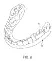
- FIG. 8shows the electronics and transducer assembly bonded or otherwise adhered directly to the surface of one or more teeth rather than being embedded or attached to a separate housing.
- FIG. 1shows an exemplary ear canal mounted hearing sub-systems 1 and 2 .
- the system of FIG. 1processes sound signals from each of two microphones 7 .
- the microphones 7are placed either at the opening or directly with the user's ear canals.
- Each of the systems 1 - 2includes a battery 3 , a signal processor 4 , a transmitter 5 , all of which can be positioned in a housing that clips onto the ear which rests behind the ear between the pinna and the skull, or alternatively can be positioned in the ear's concha.
- the transmitter 5is connected to a wire/antenna 6 that in turn is connected to the microphone 7 .
- Each transmitter 5transmits information to a receiver 8 that activates a transducer 9 that is powered by a battery 10 .
- Each side of the headcan have one set of receiver 8 , transducer 9 and battery 10 .
- This embodimentprovides a bone conduction hearing aid device with dual externally located microphones that are placed at the entrance to or in the ear canals and an oral appliance containing dual transducers in communication with each other. The device will allow the user to enjoy the most natural sound input due to the location of the microphone which takes advantage of the pinna for optimal sound localization (and directionality).
- the microphones 7receive sound, signals from both sides of the head, processes those signals to send a signal to the transducer on the side of the head where the sound is perceived by the microphone 7 to be at a higher sound level.
- a phase-shifted signalis sent to the transducer 9 on the opposite side of the head.
- the microphone 7 at the first earreceives sound signals from the first side of the head, processes those signal to send a signal to the transducer 9 on that same or first side of the oral appliance.
- a second microphone 7 at the second earreceives a sound signal that is lower in amplitude and delayed in respect to the sound sensed by the first microphone due to head shadowing and physical separation of the microphones 7 , and sends a corresponding signal to the second transducer 9 on the second side of the oral appliance.
- the sound signals from the transducers 9will be perceived by each cochlea on each side of the head as being different in amplitude and phase, which will result in the perception of directionality by the user.
- FIGS. 2-3show in more detail one exemplary mounting of hearing system 1 with the microphone 7 in the user's ear canal.
- the componentssuch as the battery 3 , the signal processor 4 , and the transmitter 5 can either be located behind the ear or within the folds of the pinna.
- the human auricleis an almost rudimentary, usually immobile shell that lies close to the side of the head with a thin plate of yellow fibrocartilage covered by closely adherent skin.
- the cartilageis molded into clearly defined hollows, ridges, and furrows that form an irregular, shallow funnel.
- the deepest depressionwhich leads directly to the external auditory canal, or acoustic meatus, is called the concha.
- the tonguelike tragus in front and the antitragus behindare partly covered by two small projections, the tonguelike tragus in front and the antitragus behind.
- a prominent ridge, the helixarises from the floor of the concha and continues as the incurved rim of the upper portion of the auricle.
- An inner, concentric ridge, the antihelixsurrounds the concha and is separated from the helix by a furrow, the scapha, also called the fossa of the helix.
- the lobule, the fleshy lower part of the auricleis the only area of the outer ear that contains no cartilage.
- the auriclealso has several small rudimentary muscles, which fasten it to the skull and scalp.
- the external auditory canalis a slightly curved tube that extends inward from the floor of the concha and ends blindly at the tympanic membrane. In its outer third the wall of the canal consists of cartilage; in its inner two-thirds, of bone.
- the anthtilx (antihelix)is a folded “Y” shaped part of the ear.
- the antitragusis the lower cartilaginous edge of the conchal bowl just above the fleshy lobule of the ear.
- the microphone 7is positioned in the ear canal.
- the microphone 7is connected with the transmitter 5 through the wire and antenna 6 .
- the placement of the microphone 7 inside the ear canalprovides the user with the most natural sound input due to the location of the microphone which takes advantage of the pinna for optimal sound localization (and directionality) when the sounds are transmitted to the cochlea using a straight signal and “phase-shifted” signal to apply directionality to the patient.
- High quality sound inputis captured by placing the microphones within or at the entrance of the ear canal which would allow the patient to use the sound reflectivity of the pinna as well as improved sound directionality due to the microphone placement.
- the arrangementavoids the need, to separate the microphone and speaker to reduce the chance of feedback and allows placement of the microphone to take advantage of the sound reflectivity of the pinna.
- the systemalso allows for better sound directionality due to the two bone conduction transducers being in electrical contact with each other. With the processing of the signals prior to being sent to the transducers and the transducers able to communicate with each other, the system provides the best sound localization possible.
- the microphone 7 shown schematically in FIG. 3includes a housing which will locate and fixate the microphone within the ear canal.
- the housingwill contain at least one, and possibly multiple opening(s) that will allow sound passage from the outside of the ear to the tympanic membrane.
- the openings in the housingwill allow sounds to pass unimpeded to the tympanic membrane for potential perception by the user if the sound is within their auditory range without amplification. This will enable perception of loud sounds by the wearer without the need for amplification by the bone conduction system.
- vibration of the tympanic membrane through coupling of bone conduction generated by speech of the wearerwill result in sound generation at the tympanic membrane; this generated sound will radiate out from the tympanic membrane, through the one or more openings in the microphone housing containing microphone 7 in FIG. 3 , reducing the effect of occlusion of the ear canal so that the wearer does not perceive abnormally loud sounds generated while speaking.
- a signal processing circuitcan be used to amplify these differences to enhance the perception of directionality.
- the brainsums the different perception at each of the two cochleas.
- one cochleareceives a high sound
- the other cochleareceives a lower sound slightly delayed compared to the first signal.
- the systempreserves this inter-aural level difference and phase shift, and delivers the first signal to the first cochlea due to proximity of the transducer to the first cochlea.
- the systemalso delivers the second signal to the second cochlea due to their proximity, and the brain sums the information to allow the user to perceive, for example that the left side got a higher signal first compared to the right side, and that is perceived by the brain as a directionality signal.
- FIG. 4illustrates a schematic representation of one variation of hearing aid assembly 14 utilizing receiving transducer 30 , which may generally include a microphone for receiving sounds and which is electrically connected to processor 32 for processing the auditory signals.
- Processor 32may be electrically connected to antenna 34 for receiving wireless communication signals, e.g., input control signals from an external remote control 36 and/or other external sound generating devices, e.g., cell phones, telephones, stereos, MP3 players, and other media players.
- the microphone 30 and processor 32may be configured to detect and process auditory signals in any practicable range, but may be configured in one variation to detect auditory signals ranging from, e.g., 250 Hertz to 20,000 Hertz.
- the detected and processed signalsmay be amplified via amplifier 44 , which increases the output levels for vibrational transmission by transducer 40 into the adjacent, or otherwise coupled, bone structure such as a patient's tooth or teeth 12 .
- microphone 30may be a digital, analog, piezoelectric, and/or directional type microphone. Such various types of microphones may be interchangeably configured to be utilized with the assembly, if so desired.
- Power supply 42may be connected to each of the components such as processor 32 and transducer 40 to provide power thereto.
- the control or other sound generated signals received by antenna 34may be in any wireless form utilizing, e.g., radio frequency, ultrasound, microwave, Blue Tooth®, among others for transmission to assembly 16 .
- the external remote control 36may be utilized such that a user may manipulate to adjust various acoustic parameters of the electronics and/or transducer assembly 16 , such as acoustic focusing, volume control, filtration, muting, frequency optimization, sound adjustments, and tone adjustments, for example.
- the signals transmittedmay be received by electronics and/or transducer assembly 16 via a receiver, which may be connected to an internal processor for additional processing of the received signals.
- the received signalsmay be communicated to transducer 40 , which may vibrate correspondingly against a surface of the tooth to conduct the vibratory signals through the tooth and bone and subsequently to the middle ear to facilitate hearing of the user.
- Transducer 40may be configured as any number of different vibratory mechanisms. For instance, in one variation, transducer 40 may be an electromagnetically actuated transducer. In other variations, transducer 40 may be in the form of a piezoelectric crystal having a range of vibratory frequencies, e.g., between 250 to 20,000 Hz.
- power supply 42may be a simple battery, replaceable or permanent, other variations may include a power supply 42 which is charged by inductance via an external charger. Additionally, power supply 42 may alternatively be charged via direct coupling 48 to an alternating current (AC) or direct current (DC) source. Other variations may include a power supply 42 which is charged via a mechanical mechanism 46 , such as an internal pendulum or slidable electrical inductance charger as known in the art, which is actuated via, e.g., motions of the jaw and/or movement for translating the mechanical motion into stored electrical energy for charging power supply 42 .
- a mechanical mechanism 46such as an internal pendulum or slidable electrical inductance charger as known in the art, which is actuated via, e.g., motions of the jaw and/or movement for translating the mechanical motion into stored electrical energy for charging power supply 42 .
- an extra-buccal transmitter assembly 22 located outside the patient's mouthmay be utilized to receive auditory signals for processing and transmission via a wireless signal 24 to the electronics and/or transducer assembly 16 positioned within the patient's mouth, which may then process and transmit the processed auditory signals via vibratory conductance to the underlying tooth and consequently to the patient's inner ear.
- the removable oral appliance 14may be optionally fabricated to have a shrinkage factor such that when placed onto the dentition, oral appliance 14 may be configured to securely grab onto the tooth or teeth as the appliance 14 may have a resulting size slightly smaller than the scanned tooth or teeth upon which the appliance 14 was formed. The fitting may result in a secure interference fit between the appliance 14 and underlying dentition.
- the transmitter assembly 22may contain a microphone assembly as well as a transmitter assembly and may be configured in any number of shapes and forms worn by the user, such as a watch, necklace, lapel, phone, belt-mounted device, etc.
- the processor 32may receive the signals through antenna 34 from external sound-generating devices 38 (as described above, e.g., cell phones, telephones, stereos, MP3 players, and other media players) as well as from other incoming sounds received from receiving transducer 30 for processing and transmission to the hearing aid assembly 14 .
- Control 36may be used to modify various parameters of the received sound while powered by battery 42 , as above.
- a hearing aid assemblymay be embedded into or configured as a custom made dental implant 54 (e.g., a permanent crown) that may be secured onto an implant post 50 previously implanted into the bone 52 , e.g., jaw bone, of a patient, as shown in FIG. 7 .
- Dental implant 54may be secured or coupled to post 50 via receiving channel 56 defined within implant 54 .
- the transducer assembly as well as the associated electronics and power supplymay be contained within implant 54 such that when implant 54 received a signal for conductance to the user, the transducer may vibrate within implant 54 to conduct the vibrations through post 50 and into the user.
- the electronics and transducer assembly 16may be bonded or otherwise adhered directly to the surface of one or more teeth 12 rather than embedded or attached to a separate housing, as shown, in FIG. 8 .
- vibrationsmay be transmitted directly into the underlying bone or tissue structures rather than transmitting directly through the tooth or teeth of the user.
- An oral appliancecan be positioned upon the user's tooth, in this example upon a molar located along the upper row of teeth.
- the electronics and/or transducer assemblycan be located along the buccal surface of the tooth.
- a conduction transmission membersuch as a rigid or solid metallic member, may be coupled to the transducer in assembly and extend from oral appliance to a post or screw which is implanted directly into the underlying bone, such as the maxillary bone.
- the vibrations generated by the transducermay be transmitted through transmission member and directly into a post or screw, which in turn transmits the vibrations directly into and through the bone for transmission to the user's inner ear.
- the above systemallows the patient to take advantage of the highest quality sound input by placing the microphone(s) within or at the entrance of the ear canal which would allow the patient to use the sound reflectivity of the pinna as well as improved sound directionality due to the microphone placement.
- Most other healing aid devicesrequire a separation of the microphone and speaker in order to reduce the chance of feedback.
- most hearing aid devicesspecifically comparing to open-fit BTE's
- the systemalso allows for better sound directionality due to the two bone conduction transducers being in electrical contact with each other. With the processing of the signals prior to being sent to the transducers and the transducers able to communicate with each other, the best sound localization is possible with this device.
- the communication devices described abovemay be implemented using one or more integrated circuits.
- a host devicemay be implemented on one integrated circuit
- the baseband processing modulemay be implemented on a second integrated circuit
- the remaining components of the radio, less the antennas,maybe implemented, on a third integrated circuit.
- the radiomay be implemented on a single integrated circuit.
- the processing module of the host device and the baseband processing modulemay be a common processing device implemented on a single integrated circuit.
- Computer readable mediacan be any available media that can be accessed by client/server devices.
- Computer readable mediamay comprise computer storage media and communication media.
- Computer storage mediaincludes volatile and nonvolatile, removable and non-removable media implemented in any method or technology for storage of information such as computer readable instructions, data structures, program modules or other data.
- Computer storage mediaincludes, but is not limited to, RAM, ROM, EEPROM, flash memory or other memory technology, CD-ROM, digital versatile disks (DVD) or other optical storage, magnetic cassettes, magnetic tape, magnetic disk storage or other magnetic storage devices, or any other medium which can be used to store the desired information and which can be accessed by client/server devices.
- Communication mediatypically embodies computer readable instructions, data structures, program modules or other data in a modulated data signal such as a carrier wave or other transport mechanism and includes any information delivery media.
Landscapes
- Health & Medical Sciences (AREA)
- General Health & Medical Sciences (AREA)
- Otolaryngology (AREA)
- Neurosurgery (AREA)
- Physics & Mathematics (AREA)
- Engineering & Computer Science (AREA)
- Acoustics & Sound (AREA)
- Signal Processing (AREA)
- Circuit For Audible Band Transducer (AREA)
- Prostheses (AREA)
- Details Of Audible-Bandwidth Transducers (AREA)
Abstract
Description
Claims (22)
Priority Applications (9)
| Application Number | Priority Date | Filing Date | Title |
|---|---|---|---|
| US11/843,541US8433080B2 (en) | 2007-08-22 | 2007-08-22 | Bone conduction hearing device with open-ear microphone |
| CN201410058330.6ACN103874003B (en) | 2007-08-22 | 2008-06-03 | Bone conduction hearing device with open-ear microphone |
| CN200880112519ACN101836466A (en) | 2007-08-22 | 2008-06-03 | Bone conduction hearing device with bare ear microphone |
| PCT/US2008/065680WO2009025917A1 (en) | 2007-08-22 | 2008-06-03 | Bone conduction hearing device with open-ear microphone |
| CA2697268ACA2697268C (en) | 2007-08-22 | 2008-06-03 | Bone conduction hearing device with open-ear microphone |
| JP2010521904AJP5586467B2 (en) | 2007-08-22 | 2008-06-03 | Open-ear bone conduction listening device |
| EP08756666.7AEP2191663B1 (en) | 2007-08-22 | 2008-06-03 | Bone conduction hearing device with open-ear microphone |
| AU2008289428AAU2008289428B2 (en) | 2007-08-22 | 2008-06-03 | Bone conduction hearing device with open-ear microphone |
| JP2013122450AJP2013211915A (en) | 2007-08-22 | 2013-06-11 | Open-ear bone conduction hearing device |
Applications Claiming Priority (1)
| Application Number | Priority Date | Filing Date | Title |
|---|---|---|---|
| US11/843,541US8433080B2 (en) | 2007-08-22 | 2007-08-22 | Bone conduction hearing device with open-ear microphone |
Publications (2)
| Publication Number | Publication Date |
|---|---|
| US20090052698A1 US20090052698A1 (en) | 2009-02-26 |
| US8433080B2true US8433080B2 (en) | 2013-04-30 |
Family
ID=40378497
Family Applications (1)
| Application Number | Title | Priority Date | Filing Date |
|---|---|---|---|
| US11/843,541Expired - Fee RelatedUS8433080B2 (en) | 2007-08-22 | 2007-08-22 | Bone conduction hearing device with open-ear microphone |
Country Status (7)
| Country | Link |
|---|---|
| US (1) | US8433080B2 (en) |
| EP (1) | EP2191663B1 (en) |
| JP (2) | JP5586467B2 (en) |
| CN (2) | CN103874003B (en) |
| AU (1) | AU2008289428B2 (en) |
| CA (1) | CA2697268C (en) |
| WO (1) | WO2009025917A1 (en) |
Cited By (19)
| Publication number | Priority date | Publication date | Assignee | Title |
|---|---|---|---|---|
| US20140275729A1 (en)* | 2013-03-15 | 2014-09-18 | Martin E. Hillbratt | Data transmission through a recipient's skull bone |
| US20150264496A1 (en)* | 2014-03-13 | 2015-09-17 | Bernafon Ag | Method for producing hearing aid fittings |
| US10075574B2 (en)* | 2013-08-23 | 2018-09-11 | Rohm Co., Ltd. | Mobile telephone |
| US10079925B2 (en) | 2012-01-20 | 2018-09-18 | Rohm Co., Ltd. | Mobile telephone |
| US10103766B2 (en) | 2013-10-24 | 2018-10-16 | Rohm Co., Ltd. | Wristband-type handset and wristband-type alerting device |
| US10158947B2 (en) | 2012-01-20 | 2018-12-18 | Rohm Co., Ltd. | Mobile telephone utilizing cartilage conduction |
| US20180376255A1 (en)* | 2008-03-31 | 2018-12-27 | John Parker | Bone conduction device fitting |
| US10348350B2 (en) | 2016-09-22 | 2019-07-09 | Sonitus Technologies, Inc. | Two-way communication system and method of use |
| US10356231B2 (en) | 2014-12-18 | 2019-07-16 | Finewell Co., Ltd. | Cartilage conduction hearing device using an electromagnetic vibration unit, and electromagnetic vibration unit |
| US10380864B2 (en) | 2014-08-20 | 2019-08-13 | Finewell Co., Ltd. | Watching system, watching detection device, and watching notification device |
| US10412512B2 (en) | 2006-05-30 | 2019-09-10 | Soundmed, Llc | Methods and apparatus for processing audio signals |
| US10484805B2 (en) | 2009-10-02 | 2019-11-19 | Soundmed, Llc | Intraoral appliance for sound transmission via bone conduction |
| US10778824B2 (en) | 2016-01-19 | 2020-09-15 | Finewell Co., Ltd. | Pen-type handset |
| US10779075B2 (en) | 2010-12-27 | 2020-09-15 | Finewell Co., Ltd. | Incoming/outgoing-talk unit and incoming-talk unit |
| US10795321B2 (en) | 2015-09-16 | 2020-10-06 | Finewell Co., Ltd. | Wrist watch with hearing function |
| US10967521B2 (en) | 2015-07-15 | 2021-04-06 | Finewell Co., Ltd. | Robot and robot system |
| US11526033B2 (en) | 2018-09-28 | 2022-12-13 | Finewell Co., Ltd. | Hearing device |
| US11683641B2 (en)* | 2017-09-12 | 2023-06-20 | Integrated Tactical Technologies, Llc | Two-way communication system and method of use |
| US11819690B2 (en) | 2007-05-31 | 2023-11-21 | Cochlear Limited | Acoustic output device with antenna |
Families Citing this family (58)
| Publication number | Priority date | Publication date | Assignee | Title |
|---|---|---|---|---|
| US20120243714A9 (en)* | 2006-05-30 | 2012-09-27 | Sonitus Medical, Inc. | Microphone placement for oral applications |
| US8291912B2 (en)* | 2006-08-22 | 2012-10-23 | Sonitus Medical, Inc. | Systems for manufacturing oral-based hearing aid appliances |
| DK2064916T3 (en)* | 2006-09-08 | 2019-03-04 | Soundmed Llc | Methods and apparatus for treating tinnitus |
| SE0701242L (en)* | 2007-05-24 | 2008-12-02 | Cochlear Ltd | Vibrator |
| US8270638B2 (en)* | 2007-05-29 | 2012-09-18 | Sonitus Medical, Inc. | Systems and methods to provide communication, positioning and monitoring of user status |
| US20080304677A1 (en)* | 2007-06-08 | 2008-12-11 | Sonitus Medical Inc. | System and method for noise cancellation with motion tracking capability |
| US20090028352A1 (en)* | 2007-07-24 | 2009-01-29 | Petroff Michael L | Signal process for the derivation of improved dtm dynamic tinnitus mitigation sound |
| US20120235632A9 (en)* | 2007-08-20 | 2012-09-20 | Sonitus Medical, Inc. | Intra-oral charging systems and methods |
| US8224013B2 (en) | 2007-08-27 | 2012-07-17 | Sonitus Medical, Inc. | Headset systems and methods |
| US7682303B2 (en) | 2007-10-02 | 2010-03-23 | Sonitus Medical, Inc. | Methods and apparatus for transmitting vibrations |
| US20090105523A1 (en)* | 2007-10-18 | 2009-04-23 | Sonitus Medical, Inc. | Systems and methods for compliance monitoring |
| US8795172B2 (en)* | 2007-12-07 | 2014-08-05 | Sonitus Medical, Inc. | Systems and methods to provide two-way communications |
| US8867765B2 (en) | 2008-02-06 | 2014-10-21 | Starkey Laboratories, Inc. | Antenna used in conjunction with the conductors for an audio transducer |
| US7974845B2 (en) | 2008-02-15 | 2011-07-05 | Sonitus Medical, Inc. | Stuttering treatment methods and apparatus |
| US8270637B2 (en)* | 2008-02-15 | 2012-09-18 | Sonitus Medical, Inc. | Headset systems and methods |
| US8023676B2 (en) | 2008-03-03 | 2011-09-20 | Sonitus Medical, Inc. | Systems and methods to provide communication and monitoring of user status |
| US20090226020A1 (en) | 2008-03-04 | 2009-09-10 | Sonitus Medical, Inc. | Dental bone conduction hearing appliance |
| US8150075B2 (en) | 2008-03-04 | 2012-04-03 | Sonitus Medical, Inc. | Dental bone conduction hearing appliance |
| EP2254345A4 (en)* | 2008-03-17 | 2012-08-29 | Temco Japan | Bone conduction speaker and listening device using same |
| US20090270673A1 (en)* | 2008-04-25 | 2009-10-29 | Sonitus Medical, Inc. | Methods and systems for tinnitus treatment |
| US9767817B2 (en)* | 2008-05-14 | 2017-09-19 | Sony Corporation | Adaptively filtering a microphone signal responsive to vibration sensed in a user's face while speaking |
| US20090296948A1 (en)* | 2008-05-29 | 2009-12-03 | Big Ear, Inc. | MPD custom ear communication device |
| DE102009014770A1 (en)* | 2009-03-25 | 2010-09-30 | Cochlear Ltd., Lane Cove | vibrator |
| USRE48797E1 (en) | 2009-03-25 | 2021-10-26 | Cochlear Limited | Bone conduction device having a multilayer piezoelectric element |
| US20110007920A1 (en)* | 2009-07-13 | 2011-01-13 | Sonitus Medical, Inc. | Intra-oral brackets for transmitting vibrations |
| US8622885B2 (en)* | 2010-02-19 | 2014-01-07 | Audiodontics, Llc | Methods and apparatus for aligning antennas of low-powered intra- and extra-oral electronic wireless devices |
| US8908891B2 (en) | 2011-03-09 | 2014-12-09 | Audiodontics, Llc | Hearing aid apparatus and method |
| US9107013B2 (en) | 2011-04-01 | 2015-08-11 | Cochlear Limited | Hearing prosthesis with a piezoelectric actuator |
| EP2637424A1 (en)* | 2012-03-07 | 2013-09-11 | Oticon Medical A/S | An acoustical transmission means and method for transmitting sound |
| EP2839151B1 (en)* | 2012-04-20 | 2017-08-30 | Sonomax Technologies Inc. | Energy harvester device for in-ear devices using ear canal dynamic motion |
| US9049527B2 (en)* | 2012-08-28 | 2015-06-02 | Cochlear Limited | Removable attachment of a passive transcutaneous bone conduction device with limited skin deformation |
| KR102081797B1 (en)* | 2012-12-13 | 2020-04-14 | 삼성전자주식회사 | Glass apparatus and Method for controlling glass apparatus, Audio apparatus and Method for providing audio signal and Display apparatus |
| US9571941B2 (en) | 2013-08-19 | 2017-02-14 | Knowles Electronics, Llc | Dynamic driver in hearing instrument |
| US11412334B2 (en)* | 2013-10-23 | 2022-08-09 | Cochlear Limited | Contralateral sound capture with respect to stimulation energy source |
| KR101388960B1 (en)* | 2014-01-20 | 2014-04-29 | 김병건 | Implant teeth connector for wireless communication, and communication system thereof |
| WO2016147170A1 (en)* | 2015-03-13 | 2016-09-22 | Woojer Ltd | A system for providing vibrations remotely from a vibrating transducer |
| US9847093B2 (en)* | 2015-06-19 | 2017-12-19 | Samsung Electronics Co., Ltd. | Method and apparatus for processing speech signal |
| CN106817661A (en)* | 2015-11-30 | 2017-06-09 | 深圳富泰宏精密工业有限公司 | Hearing assistant system and electronic installation |
| EP3185588A1 (en)* | 2015-12-22 | 2017-06-28 | Oticon A/s | A hearing device comprising a feedback detector |
| US9774941B2 (en) | 2016-01-19 | 2017-09-26 | Apple Inc. | In-ear speaker hybrid audio transparency system |
| GB2554632B (en)* | 2016-05-24 | 2021-02-24 | Inova Design Solution Ltd | Portable physiology monitor |
| DK3288294T3 (en)* | 2016-08-26 | 2019-10-07 | Interacoustics As | IN-SITU COMPENSATION OF ACOUSTIC MEASUREMENTS |
| JP2018046525A (en)* | 2016-09-16 | 2018-03-22 | カシオ計算機株式会社 | Bone conduction wave generating device, bone conduction wave generation method, program for bone conduction wave generating device, and bone conduction wave output machine |
| AU2017353702B2 (en)* | 2016-11-01 | 2020-06-11 | Med-El Elektromedizinische Geraete Gmbh | Adaptive noise cancelling of bone conducted noise in the mechanical domain |
| CN107017001B (en)* | 2017-03-28 | 2020-05-22 | 广东小天才科技有限公司 | Wearable device audio signal output processing method and wearable device |
| GB201713946D0 (en)* | 2017-06-16 | 2017-10-18 | Cirrus Logic Int Semiconductor Ltd | Earbud speech estimation |
| US10231046B1 (en)* | 2017-08-18 | 2019-03-12 | Facebook Technologies, Llc | Cartilage conduction audio system for eyewear devices |
| CN208675541U (en) | 2018-06-26 | 2019-03-29 | 声佗医疗科技(上海)有限公司 | A kind of bone conduction hearing equipment |
| WO2020076637A1 (en)* | 2018-10-08 | 2020-04-16 | Nanoear Corporation, Inc. | Compact hearing aids |
| US11223913B2 (en) | 2018-10-08 | 2022-01-11 | Nanoear Corporation, Inc. | Compact hearing aids |
| JP7502010B2 (en)* | 2019-10-11 | 2024-06-18 | リオン株式会社 | Listening devices and earphones |
| AU2021204888A1 (en)* | 2020-01-03 | 2022-08-25 | Luzidy, Llc | Wireless audio transmitter and receiver bone device using bone conduction |
| BR112022017897A2 (en) | 2020-03-31 | 2022-11-01 | Shenzhen Shokz Co Ltd | ACOUSTIC OUTPUT DEVICE |
| US20230164499A1 (en)* | 2020-04-27 | 2023-05-25 | Cochlear Limited | Pinnal device |
| WO2021243558A1 (en) | 2020-06-02 | 2021-12-09 | 雷铭科技有限公司 | Integrated bone-conduction sound production device and method |
| CN113709645B (en)* | 2021-09-02 | 2025-04-15 | 声佗医疗科技(上海)有限公司 | Hearing aid and its intraoral device, external device, control method and control device, and storage device |
| CN113891213B (en)* | 2021-10-26 | 2023-11-03 | 苏州登堡电子科技有限公司 | Optimize bone conduction earphone |
| JP7465570B2 (en)* | 2022-04-10 | 2024-04-11 | 合同会社Medical EMW systems | Bone conduction hearing aids |
Citations (150)
| Publication number | Priority date | Publication date | Assignee | Title |
|---|---|---|---|---|
| US2045404A (en) | 1933-05-24 | 1936-06-23 | Sonotone Corp | Piezoelectric vibrator device |
| US2161169A (en) | 1938-01-24 | 1939-06-06 | Erwin H Wilson | Dentiphone |
| US2318872A (en) | 1941-07-17 | 1943-05-11 | Goodman Mfg Co | Extensible conveyer |
| US2977425A (en) | 1959-09-14 | 1961-03-28 | Irwin H Cole | Hearing aid |
| US2995633A (en) | 1958-09-25 | 1961-08-08 | Henry K Puharich | Means for aiding hearing |
| US3156787A (en) | 1962-10-23 | 1964-11-10 | Henry K Puharich | Solid state hearing system |
| US3170993A (en) | 1962-01-08 | 1965-02-23 | Henry K Puharich | Means for aiding hearing by electrical stimulation of the facial nerve system |
| US3267931A (en) | 1963-01-09 | 1966-08-23 | Henry K Puharich | Electrically stimulated hearing with signal feedback |
| US3325743A (en) | 1965-12-23 | 1967-06-13 | Zenith Radio Corp | Bimorph flexural acoustic amplifier |
| US3787641A (en) | 1972-06-05 | 1974-01-22 | Setcom Corp | Bone conduction microphone assembly |
| US3894196A (en)* | 1974-05-28 | 1975-07-08 | Zenith Radio Corp | Binaural hearing aid system |
| US3985977A (en) | 1975-04-21 | 1976-10-12 | Motorola, Inc. | Receiver system for receiving audio electrical signals |
| US4025732A (en) | 1975-08-04 | 1977-05-24 | Hartmut Traunmuller | Method and device for presenting information to deaf persons |
| US4150262A (en) | 1974-11-18 | 1979-04-17 | Hiroshi Ono | Piezoelectric bone conductive in ear voice sounds transmitting and receiving apparatus |
| US4498461A (en) | 1981-12-01 | 1985-02-12 | Bo Hakansson | Coupling to a bone-anchored hearing aid |
| US4591668A (en) | 1984-05-08 | 1986-05-27 | Iwata Electric Co., Ltd. | Vibration-detecting type microphone |
| US4612915A (en) | 1985-05-23 | 1986-09-23 | Xomed, Inc. | Direct bone conduction hearing aid device |
| US4642769A (en) | 1983-06-10 | 1987-02-10 | Wright State University | Method and apparatus for providing stimulated exercise of paralyzed limbs |
| US4738268A (en) | 1985-07-24 | 1988-04-19 | Tokos Medical Corporation | Relative time clock |
| US4791673A (en) | 1986-12-04 | 1988-12-13 | Schreiber Simeon B | Bone conduction audio listening device and method |
| US4817044A (en) | 1987-06-01 | 1989-03-28 | Ogren David A | Collection and reporting system for medical appliances |
| US4832033A (en) | 1985-04-29 | 1989-05-23 | Bio-Medical Research Limited | Electrical stimulation of muscle |
| US4920984A (en) | 1986-10-15 | 1990-05-01 | Sunstar Kabushiki Kaisha | Mouthpiece and method for producing the same |
| US4982434A (en) | 1989-05-30 | 1991-01-01 | Center For Innovative Technology | Supersonic bone conduction hearing aid and method |
| US5012520A (en) | 1988-05-06 | 1991-04-30 | Siemens Aktiengesellschaft | Hearing aid with wireless remote control |
| US5033999A (en) | 1989-10-25 | 1991-07-23 | Mersky Barry L | Method and apparatus for endodontically augmenting hearing |
| US5047994A (en) | 1989-05-30 | 1991-09-10 | Center For Innovative Technology | Supersonic bone conduction hearing aid and method |
| US5060526A (en) | 1989-05-30 | 1991-10-29 | Schlumberger Industries, Inc. | Laminated semiconductor sensor with vibrating element |
| US5082007A (en) | 1990-01-24 | 1992-01-21 | Loren S. Adell | Multi-laminar mouthguards |
| US5233987A (en) | 1992-07-09 | 1993-08-10 | Empi, Inc. | System and method for monitoring patient's compliance |
| US5323468A (en) | 1992-06-30 | 1994-06-21 | Bottesch H Werner | Bone-conductive stereo headphones |
| US5325436A (en) | 1993-06-30 | 1994-06-28 | House Ear Institute | Method of signal processing for maintaining directional hearing with hearing aids |
| US5372142A (en) | 1993-02-17 | 1994-12-13 | Poul Madsen Medical Devices Ltd. | Cochlear response audiometer |
| US5402496A (en) | 1992-07-13 | 1995-03-28 | Minnesota Mining And Manufacturing Company | Auditory prosthesis, noise suppression apparatus and feedback suppression apparatus having focused adaptive filtering |
| US5403262A (en) | 1993-03-09 | 1995-04-04 | Microtek Medical, Inc. | Minimum energy tinnitus masker |
| US5447489A (en)* | 1989-08-17 | 1995-09-05 | Issalene; Robert | Bone conduction hearing aid device |
| US5455842A (en) | 1994-01-12 | 1995-10-03 | Mersky; Barry | Method and apparatus for underwater communication |
| US5460593A (en) | 1993-08-25 | 1995-10-24 | Audiodontics, Inc. | Method and apparatus for imparting low amplitude vibrations to bone and similar hard tissue |
| EP0715838A2 (en) | 1994-12-02 | 1996-06-12 | P & B RESEARCH AB | A device in hearing aids |
| US5546459A (en) | 1993-11-01 | 1996-08-13 | Qualcomm Incorporated | Variable block size adaptation algorithm for noise-robust acoustic echo cancellation |
| US5558618A (en) | 1995-01-23 | 1996-09-24 | Maniglia; Anthony J. | Semi-implantable middle ear hearing device |
| US5565759A (en) | 1994-12-15 | 1996-10-15 | Intel Corporation | Smart battery providing battery life and recharge time prediction |
| US5616027A (en) | 1995-04-18 | 1997-04-01 | Jacobs; Allison J. | Custom dental tray |
| US5624376A (en) | 1993-07-01 | 1997-04-29 | Symphonix Devices, Inc. | Implantable and external hearing systems having a floating mass transducer |
| US5659156A (en)* | 1995-02-03 | 1997-08-19 | Jabra Corporation | Earmolds for two-way communications devices |
| US5661813A (en) | 1994-10-26 | 1997-08-26 | Nippon Telegraph And Telephone Corporation | Method and apparatus for multi-channel acoustic echo cancellation |
| US5706251A (en) | 1995-07-21 | 1998-01-06 | Trigger Scuba, Inc. | Scuba diving voice and communication system using bone conducted sound |
| EP0824889A1 (en) | 1996-08-20 | 1998-02-25 | Buratto Advanced Technology S.r.l. | Transmission system using the human body as wave guide |
| US5760692A (en) | 1996-10-18 | 1998-06-02 | Block; Douglas A. | Intra-oral tracking device |
| US5800336A (en) | 1993-07-01 | 1998-09-01 | Symphonix Devices, Inc. | Advanced designs of floating mass transducers |
| US5812496A (en) | 1997-10-20 | 1998-09-22 | Peck/Pelissier Partnership | Water resistant microphone |
| US5828765A (en) | 1996-05-03 | 1998-10-27 | Gable; Tony L. | Audio loudspeaker assembly for recessed lighting fixture and audio system using same |
| US5902167A (en) | 1997-09-09 | 1999-05-11 | Sonic Bites, Llc | Sound-transmitting amusement device and method |
| US5914701A (en) | 1995-05-08 | 1999-06-22 | Massachusetts Institute Of Technology | Non-contact system for sensing and signalling by externally induced intra-body currents |
| US5961443A (en) | 1996-07-31 | 1999-10-05 | East Carolina University | Therapeutic device to ameliorate stuttering |
| US5984681A (en) | 1997-09-02 | 1999-11-16 | Huang; Barney K. | Dental implant and method of implanting |
| US6029558A (en) | 1997-05-12 | 2000-02-29 | Southwest Research Institute | Reactive personnel protection system |
| US6047074A (en) | 1996-07-09 | 2000-04-04 | Zoels; Fred | Programmable hearing aid operable in a mode for tinnitus therapy |
| US6068590A (en) | 1997-10-24 | 2000-05-30 | Hearing Innovations, Inc. | Device for diagnosing and treating hearing disorders |
| US6072885A (en) | 1994-07-08 | 2000-06-06 | Sonic Innovations, Inc. | Hearing aid device incorporating signal processing techniques |
| US6072884A (en) | 1997-11-18 | 2000-06-06 | Audiologic Hearing Systems Lp | Feedback cancellation apparatus and methods |
| US6075557A (en) | 1997-04-17 | 2000-06-13 | Sharp Kabushiki Kaisha | Image tracking system and method and observer tracking autostereoscopic display |
| US6115477A (en) | 1995-01-23 | 2000-09-05 | Sonic Bites, Llc | Denta-mandibular sound-transmitting system |
| US6118882A (en) | 1995-01-25 | 2000-09-12 | Haynes; Philip Ashley | Communication method |
| US6171229B1 (en) | 1996-08-07 | 2001-01-09 | St. Croix Medical, Inc. | Ossicular transducer attachment for an implantable hearing device |
| US6223018B1 (en) | 1996-12-12 | 2001-04-24 | Nippon Telegraph And Telephone Corporation | Intra-body information transfer device |
| US6239705B1 (en) | 2000-04-19 | 2001-05-29 | Jeffrey Glen | Intra oral electronic tracking device |
| US20010003788A1 (en) | 1993-07-01 | 2001-06-14 | Ball Geoffrey R. | Implantable and external hearing system having a floating mass transducer |
| US20010051776A1 (en) | 1998-10-14 | 2001-12-13 | Lenhardt Martin L. | Tinnitus masker/suppressor |
| US6333269B2 (en) | 1997-09-16 | 2001-12-25 | Tokyo Electron Limited | Plasma treatment system and method |
| US20020026091A1 (en) | 2000-08-25 | 2002-02-28 | Hans Leysieffer | Implantable hearing system with means for measuring its coupling quality |
| US6377693B1 (en) | 1994-06-23 | 2002-04-23 | Hearing Innovations Incorporated | Tinnitus masking using ultrasonic signals |
| US6394969B1 (en) | 1998-10-14 | 2002-05-28 | Sound Techniques Systems Llc | Tinnitis masking and suppressor using pulsed ultrasound |
| US20020071581A1 (en)* | 2000-03-28 | 2002-06-13 | Hans Leysieffer | Partially or fully implantable hearing system |
| US20020077831A1 (en) | 2000-11-28 | 2002-06-20 | Numa Takayuki | Data input/output method and system without being notified |
| US20020122563A1 (en) | 2001-03-02 | 2002-09-05 | Schumaier Daniel R. | Bone conduction hearing aid |
| US6504942B1 (en) | 1998-01-23 | 2003-01-07 | Sharp Kabushiki Kaisha | Method of and apparatus for detecting a face-like region and observer tracking display |
| US6538558B2 (en) | 1996-09-20 | 2003-03-25 | Alps Electric Co., Ltd. | Communication system |
| US20030059078A1 (en) | 2001-06-21 | 2003-03-27 | Downs Edward F. | Directional sensors for head-mounted contact microphones |
| EP1299052A1 (en) | 2000-07-12 | 2003-04-09 | Entific Medical Systems AB | Anchoring element |
| US20030091200A1 (en) | 2001-10-09 | 2003-05-15 | Pompei Frank Joseph | Ultrasonic transducer for parametric array |
| US6585637B2 (en) | 1998-10-15 | 2003-07-01 | St. Croix Medical, Inc. | Method and apparatus for fixation type feedback reduction in implantable hearing assistance systems |
| US6631197B1 (en) | 2000-07-24 | 2003-10-07 | Gn Resound North America Corporation | Wide audio bandwidth transduction method and device |
| US6633747B1 (en) | 2000-07-12 | 2003-10-14 | Lucent Technologies Inc. | Orthodontic appliance audio receiver |
| US20030212319A1 (en) | 2000-10-10 | 2003-11-13 | Magill Alan Remy | Health monitoring garment |
| US6682472B1 (en) | 1999-03-17 | 2004-01-27 | Tinnitech Ltd. | Tinnitus rehabilitation device and method |
| US20040057591A1 (en) | 2002-06-26 | 2004-03-25 | Frank Beck | Directional hearing given binaural hearing aid coverage |
| US6754472B1 (en) | 2000-04-27 | 2004-06-22 | Microsoft Corporation | Method and apparatus for transmitting power and data using the human body |
| US20040141624A1 (en) | 1999-03-17 | 2004-07-22 | Neuromonics Limited | Tinnitus rehabilitation device and method |
| US6778674B1 (en) | 1999-12-28 | 2004-08-17 | Texas Instruments Incorporated | Hearing assist device with directional detection and sound modification |
| US20040202339A1 (en) | 2003-04-09 | 2004-10-14 | O'brien, William D. | Intrabody communication with ultrasound |
| US20040202344A1 (en) | 2003-04-08 | 2004-10-14 | Muniswamappa Anjanappa | Method and apparatus for tooth bone conduction microphone |
| US6826284B1 (en) | 2000-02-04 | 2004-11-30 | Agere Systems Inc. | Method and apparatus for passive acoustic source localization for video camera steering applications |
| US20040243481A1 (en) | 2000-04-05 | 2004-12-02 | Therics, Inc. | System and method for rapidly customizing design, manufacture and/or selection of biomedical devices |
| US20040247143A1 (en) | 2001-10-01 | 2004-12-09 | Amphicom | Device for listening to voice and/or musical signals by means of cranial bone transmission |
| US20050037312A1 (en) | 2003-06-20 | 2005-02-17 | Aso International, Inc | Orthodontic retainer |
| US20050067816A1 (en) | 2002-12-18 | 2005-03-31 | Buckman Robert F. | Method and apparatus for body impact protection |
| US20050070782A1 (en) | 2003-07-17 | 2005-03-31 | Dmitri Brodkin | Digital technologies for planning and carrying out dental restorative procedures |
| US6885753B2 (en) | 2000-01-27 | 2005-04-26 | New Transducers Limited | Communication device using bone conduction |
| US20050129257A1 (en) | 2003-12-12 | 2005-06-16 | Nec Tokin Corporation | Acoustic vibration generating element |
| US6917688B2 (en) | 2002-09-11 | 2005-07-12 | Nanyang Technological University | Adaptive noise cancelling microphone system |
| US20050196008A1 (en) | 2003-04-08 | 2005-09-08 | Muniswamappa Anjanappa | Method and apparatus for tooth bone conduction microphone |
| US6941952B1 (en) | 2004-12-02 | 2005-09-13 | Rush, Iii Gus A. | Athletic mouthpiece capable of sensing linear and rotational forces and protective headgear for use with the same |
| US6954668B1 (en) | 2001-10-11 | 2005-10-11 | Cuozzo John W | Apparatus and method for intra-oral stimulation of the trigeminal nerve |
| US20050241646A1 (en) | 2004-03-10 | 2005-11-03 | Apneos Corp. | System and method for treatment of upper airway disorders |
| US6985599B2 (en) | 2000-06-02 | 2006-01-10 | P&B Research Ab | Vibrator for bone conducted hearing aids |
| US20060008106A1 (en) | 2004-07-06 | 2006-01-12 | Harper Patrick S | System and method for securing headphone transducers |
| US20060025648A1 (en) | 2002-12-11 | 2006-02-02 | No. 182 Corporate Ventures Ltd. | Surgically implantable hearing aid |
| US7003099B1 (en) | 2002-11-15 | 2006-02-21 | Fortmedia, Inc. | Small array microphone for acoustic echo cancellation and noise suppression |
| EP1633284A1 (en) | 2003-05-30 | 2006-03-15 | Entific Medical Systems AB | Implant device |
| US20060064037A1 (en) | 2004-09-22 | 2006-03-23 | Shalon Ventures Research, Llc | Systems and methods for monitoring and modifying behavior |
| US7035415B2 (en) | 2000-05-26 | 2006-04-25 | Koninklijke Philips Electronics N.V. | Method and device for acoustic echo cancellation combined with adaptive beamforming |
| US7076077B2 (en) | 2001-07-05 | 2006-07-11 | Temco Japan Co., Ltd. | Bone conduction headset |
| US20060167335A1 (en) | 2005-01-26 | 2006-07-27 | Samsung Electronics Co., Ltd. | Method and device for tinnitus therapy |
| US7099822B2 (en) | 2002-12-10 | 2006-08-29 | Liberato Technologies, Inc. | System and method for noise reduction having first and second adaptive filters responsive to a stored vector |
| EP1718255A1 (en) | 2003-10-22 | 2006-11-08 | Entific Medical Systems AB | Anti-stuttering device |
| US20060270467A1 (en) | 2005-05-25 | 2006-11-30 | Song Jianming J | Method and apparatus of increasing speech intelligibility in noisy environments |
| US20060275739A1 (en) | 2005-06-03 | 2006-12-07 | Ray Charles D | Dental vibrator and acoustical unit with method for the inhibition of operative pain |
| US7162420B2 (en) | 2002-12-10 | 2007-01-09 | Liberato Technologies, Llc | System and method for noise reduction having first and second adaptive filters |
| US7171003B1 (en) | 2000-10-19 | 2007-01-30 | Lear Corporation | Robust and reliable acoustic echo and noise cancellation system for cabin communication |
| US7171008B2 (en) | 2002-02-05 | 2007-01-30 | Mh Acoustics, Llc | Reducing noise in audio systems |
| US7174022B1 (en) | 2002-11-15 | 2007-02-06 | Fortemedia, Inc. | Small array microphone for beam-forming and noise suppression |
| US20070036370A1 (en) | 2004-10-12 | 2007-02-15 | Microsoft Corporation | Method and apparatus for multi-sensory speech enhancement on a mobile device |
| US20070041595A1 (en) | 2005-07-07 | 2007-02-22 | Carazo Alfredo V | Bone-conduction hearing-aid transducer having improved frequency response |
| US7206423B1 (en) | 2000-05-10 | 2007-04-17 | Board Of Trustees Of University Of Illinois | Intrabody communication for a hearing aid |
| EP1783919A1 (en) | 2004-08-27 | 2007-05-09 | Victorion Technology Co., Ltd. | The nasal bone conduction wireless communication transmission equipment |
| US20070142072A1 (en) | 2005-12-19 | 2007-06-21 | Teodoro Lassally | Two way radio |
| US7246058B2 (en) | 2001-05-30 | 2007-07-17 | Aliph, Inc. | Detecting voiced and unvoiced speech using both acoustic and nonacoustic sensors |
| US7258533B2 (en) | 2004-12-30 | 2007-08-21 | Adaptivenergy, Llc | Method and apparatus for scavenging energy during pump operation |
| US7271569B2 (en) | 2004-09-21 | 2007-09-18 | Motorola Inc. | Contact less charger with alignment indicator |
| US20070265533A1 (en) | 2006-05-12 | 2007-11-15 | Bao Tran | Cuffless blood pressure monitoring appliance |
| US20070276270A1 (en) | 2006-05-24 | 2007-11-29 | Bao Tran | Mesh network stroke monitoring appliance |
| US20070280491A1 (en) | 2006-05-30 | 2007-12-06 | Sonitus Medical, Inc. | Methods and apparatus for processing audio signals |
| US7310427B2 (en) | 2002-08-01 | 2007-12-18 | Virginia Commonwealth University | Recreational bone conduction audio device, system |
| US20080019557A1 (en) | 2006-07-19 | 2008-01-24 | Bevirt Joeben | Headset with fit adjustments and magnetic accessories |
| US20080021327A1 (en) | 2006-05-12 | 2008-01-24 | Tarek Hessin Ahmed El-Bialy | Ultrasound stimulation devices and techniques |
| US7329226B1 (en) | 2004-07-06 | 2008-02-12 | Cardiac Pacemakers, Inc. | System and method for assessing pulmonary performance through transthoracic impedance monitoring |
| US7333624B2 (en) | 2003-09-24 | 2008-02-19 | Siemens Audiologische Technik Gmbh | Hearing aid device and operating method for automatically switching voltage supply to a connected external device |
| US7331349B2 (en) | 2003-01-23 | 2008-02-19 | Surgical Devices, Ltd., Co. Morningstar Holding Ltd. | Method and device for the prevention of snoring and sleep apnea |
| US20080064993A1 (en) | 2006-09-08 | 2008-03-13 | Sonitus Medical Inc. | Methods and apparatus for treating tinnitus |
| US20080070181A1 (en) | 2006-08-22 | 2008-03-20 | Sonitus Medical, Inc. | Systems for manufacturing oral-based hearing aid appliances |
| US7361216B2 (en) | 2004-05-17 | 2008-04-22 | 3M Innovative Properties Company | Dental compositions containing nanofillers and related methods |
| US20080304677A1 (en) | 2007-06-08 | 2008-12-11 | Sonitus Medical Inc. | System and method for noise cancellation with motion tracking capability |
| US20090028352A1 (en) | 2007-07-24 | 2009-01-29 | Petroff Michael L | Signal process for the derivation of improved dtm dynamic tinnitus mitigation sound |
| US20090088598A1 (en) | 2007-10-02 | 2009-04-02 | Sonitus Medical, Inc. | Methods and apparatus for transmitting vibrations |
| US7522740B2 (en) | 2000-01-07 | 2009-04-21 | Etymotic Research, Inc. | Multi-coil coupling system for hearing aid applications |
| US7522738B2 (en) | 2005-11-30 | 2009-04-21 | Otologics, Llc | Dual feedback control system for implantable hearing instrument |
| US20090105523A1 (en) | 2007-10-18 | 2009-04-23 | Sonitus Medical, Inc. | Systems and methods for compliance monitoring |
| US20090149722A1 (en) | 2007-12-07 | 2009-06-11 | Sonitus Medical, Inc. | Systems and methods to provide two-way communications |
| US20090147976A1 (en) | 2006-09-08 | 2009-06-11 | Sonitus Medical, Inc. | Tinnitus masking systems |
Family Cites Families (12)
| Publication number | Priority date | Publication date | Assignee | Title |
|---|---|---|---|---|
| JPS546329Y2 (en)* | 1974-11-28 | 1979-03-24 | ||
| JPS5222403A (en)* | 1975-08-13 | 1977-02-19 | Seiko Epson Corp | Hearing aid |
| JPS62159099U (en)* | 1986-03-31 | 1987-10-08 | ||
| CN1045211A (en)* | 1990-04-11 | 1990-09-05 | 刘绍新 | Without ear to hear auditory prosthesis |
| US5318872A (en)* | 1993-04-02 | 1994-06-07 | Xerox Corporation | Toner and developer compositions with fluorophosphate charge enhancing additives |
| US5721783A (en)* | 1995-06-07 | 1998-02-24 | Anderson; James C. | Hearing aid with wireless remote processor |
| CN2572704Y (en)* | 2002-09-05 | 2003-09-10 | 严建敏 | Bone conductive hearing-aid |
| JP2004205839A (en)* | 2002-12-25 | 2004-07-22 | Fuji Iryoki:Kk | Hearing aid |
| US7302071B2 (en) | 2004-09-15 | 2007-11-27 | Schumaier Daniel R | Bone conduction hearing assistance device |
| JP2006217088A (en)* | 2005-02-01 | 2006-08-17 | Sharp Corp | Auditory transmission system |
| JP3866748B2 (en)* | 2005-02-22 | 2007-01-10 | リオン株式会社 | Waterproof hearing aid |
| WO2007140368A2 (en)* | 2006-05-30 | 2007-12-06 | Sonitus Medical, Inc. | Methods and apparatus for processing audio signals |
- 2007
- 2007-08-22USUS11/843,541patent/US8433080B2/ennot_activeExpired - Fee Related
- 2008
- 2008-06-03CACA2697268Apatent/CA2697268C/ennot_activeExpired - Fee Related
- 2008-06-03JPJP2010521904Apatent/JP5586467B2/enactiveActive
- 2008-06-03AUAU2008289428Apatent/AU2008289428B2/ennot_activeCeased
- 2008-06-03CNCN201410058330.6Apatent/CN103874003B/enactiveActive
- 2008-06-03CNCN200880112519Apatent/CN101836466A/enactivePending
- 2008-06-03WOPCT/US2008/065680patent/WO2009025917A1/enactiveApplication Filing
- 2008-06-03EPEP08756666.7Apatent/EP2191663B1/enactiveActive
- 2013
- 2013-06-11JPJP2013122450Apatent/JP2013211915A/ennot_activeWithdrawn
Patent Citations (173)
| Publication number | Priority date | Publication date | Assignee | Title |
|---|---|---|---|---|
| US2045404A (en) | 1933-05-24 | 1936-06-23 | Sonotone Corp | Piezoelectric vibrator device |
| US2161169A (en) | 1938-01-24 | 1939-06-06 | Erwin H Wilson | Dentiphone |
| US2318872A (en) | 1941-07-17 | 1943-05-11 | Goodman Mfg Co | Extensible conveyer |
| US2995633A (en) | 1958-09-25 | 1961-08-08 | Henry K Puharich | Means for aiding hearing |
| US2977425A (en) | 1959-09-14 | 1961-03-28 | Irwin H Cole | Hearing aid |
| US3170993A (en) | 1962-01-08 | 1965-02-23 | Henry K Puharich | Means for aiding hearing by electrical stimulation of the facial nerve system |
| US3156787A (en) | 1962-10-23 | 1964-11-10 | Henry K Puharich | Solid state hearing system |
| US3267931A (en) | 1963-01-09 | 1966-08-23 | Henry K Puharich | Electrically stimulated hearing with signal feedback |
| US3325743A (en) | 1965-12-23 | 1967-06-13 | Zenith Radio Corp | Bimorph flexural acoustic amplifier |
| US3787641A (en) | 1972-06-05 | 1974-01-22 | Setcom Corp | Bone conduction microphone assembly |
| US3894196A (en)* | 1974-05-28 | 1975-07-08 | Zenith Radio Corp | Binaural hearing aid system |
| US4150262A (en) | 1974-11-18 | 1979-04-17 | Hiroshi Ono | Piezoelectric bone conductive in ear voice sounds transmitting and receiving apparatus |
| US3985977A (en) | 1975-04-21 | 1976-10-12 | Motorola, Inc. | Receiver system for receiving audio electrical signals |
| US4025732A (en) | 1975-08-04 | 1977-05-24 | Hartmut Traunmuller | Method and device for presenting information to deaf persons |
| US4498461A (en) | 1981-12-01 | 1985-02-12 | Bo Hakansson | Coupling to a bone-anchored hearing aid |
| US4642769A (en) | 1983-06-10 | 1987-02-10 | Wright State University | Method and apparatus for providing stimulated exercise of paralyzed limbs |
| US4591668A (en) | 1984-05-08 | 1986-05-27 | Iwata Electric Co., Ltd. | Vibration-detecting type microphone |
| US4832033A (en) | 1985-04-29 | 1989-05-23 | Bio-Medical Research Limited | Electrical stimulation of muscle |
| US4612915A (en) | 1985-05-23 | 1986-09-23 | Xomed, Inc. | Direct bone conduction hearing aid device |
| US4738268A (en) | 1985-07-24 | 1988-04-19 | Tokos Medical Corporation | Relative time clock |
| US4920984A (en) | 1986-10-15 | 1990-05-01 | Sunstar Kabushiki Kaisha | Mouthpiece and method for producing the same |
| US4791673A (en) | 1986-12-04 | 1988-12-13 | Schreiber Simeon B | Bone conduction audio listening device and method |
| US4817044A (en) | 1987-06-01 | 1989-03-28 | Ogren David A | Collection and reporting system for medical appliances |
| US5012520A (en) | 1988-05-06 | 1991-04-30 | Siemens Aktiengesellschaft | Hearing aid with wireless remote control |
| US4982434A (en) | 1989-05-30 | 1991-01-01 | Center For Innovative Technology | Supersonic bone conduction hearing aid and method |
| US5047994A (en) | 1989-05-30 | 1991-09-10 | Center For Innovative Technology | Supersonic bone conduction hearing aid and method |
| US5060526A (en) | 1989-05-30 | 1991-10-29 | Schlumberger Industries, Inc. | Laminated semiconductor sensor with vibrating element |
| US5447489A (en)* | 1989-08-17 | 1995-09-05 | Issalene; Robert | Bone conduction hearing aid device |
| US5033999A (en) | 1989-10-25 | 1991-07-23 | Mersky Barry L | Method and apparatus for endodontically augmenting hearing |
| US5082007A (en) | 1990-01-24 | 1992-01-21 | Loren S. Adell | Multi-laminar mouthguards |
| US5323468A (en) | 1992-06-30 | 1994-06-21 | Bottesch H Werner | Bone-conductive stereo headphones |
| US5233987A (en) | 1992-07-09 | 1993-08-10 | Empi, Inc. | System and method for monitoring patient's compliance |
| US5402496A (en) | 1992-07-13 | 1995-03-28 | Minnesota Mining And Manufacturing Company | Auditory prosthesis, noise suppression apparatus and feedback suppression apparatus having focused adaptive filtering |
| US5372142A (en) | 1993-02-17 | 1994-12-13 | Poul Madsen Medical Devices Ltd. | Cochlear response audiometer |
| US5403262A (en) | 1993-03-09 | 1995-04-04 | Microtek Medical, Inc. | Minimum energy tinnitus masker |
| US5325436A (en) | 1993-06-30 | 1994-06-28 | House Ear Institute | Method of signal processing for maintaining directional hearing with hearing aids |
| US5624376A (en) | 1993-07-01 | 1997-04-29 | Symphonix Devices, Inc. | Implantable and external hearing systems having a floating mass transducer |
| US5800336A (en) | 1993-07-01 | 1998-09-01 | Symphonix Devices, Inc. | Advanced designs of floating mass transducers |
| US20010003788A1 (en) | 1993-07-01 | 2001-06-14 | Ball Geoffrey R. | Implantable and external hearing system having a floating mass transducer |
| US5460593A (en) | 1993-08-25 | 1995-10-24 | Audiodontics, Inc. | Method and apparatus for imparting low amplitude vibrations to bone and similar hard tissue |
| US5546459A (en) | 1993-11-01 | 1996-08-13 | Qualcomm Incorporated | Variable block size adaptation algorithm for noise-robust acoustic echo cancellation |
| EP0741940A1 (en) | 1994-01-12 | 1996-11-13 | Barry Mersky | Method and apparatus for underwater communication |
| US5455842A (en) | 1994-01-12 | 1995-10-03 | Mersky; Barry | Method and apparatus for underwater communication |
| US6377693B1 (en) | 1994-06-23 | 2002-04-23 | Hearing Innovations Incorporated | Tinnitus masking using ultrasonic signals |
| US6072885A (en) | 1994-07-08 | 2000-06-06 | Sonic Innovations, Inc. | Hearing aid device incorporating signal processing techniques |
| US5661813A (en) | 1994-10-26 | 1997-08-26 | Nippon Telegraph And Telephone Corporation | Method and apparatus for multi-channel acoustic echo cancellation |
| EP0715838A2 (en) | 1994-12-02 | 1996-06-12 | P & B RESEARCH AB | A device in hearing aids |
| US5565759A (en) | 1994-12-15 | 1996-10-15 | Intel Corporation | Smart battery providing battery life and recharge time prediction |
| US5558618A (en) | 1995-01-23 | 1996-09-24 | Maniglia; Anthony J. | Semi-implantable middle ear hearing device |
| US6115477A (en) | 1995-01-23 | 2000-09-05 | Sonic Bites, Llc | Denta-mandibular sound-transmitting system |
| US6118882A (en) | 1995-01-25 | 2000-09-12 | Haynes; Philip Ashley | Communication method |
| US5659156A (en)* | 1995-02-03 | 1997-08-19 | Jabra Corporation | Earmolds for two-way communications devices |
| US5616027A (en) | 1995-04-18 | 1997-04-01 | Jacobs; Allison J. | Custom dental tray |
| US5914701A (en) | 1995-05-08 | 1999-06-22 | Massachusetts Institute Of Technology | Non-contact system for sensing and signalling by externally induced intra-body currents |
| US5706251A (en) | 1995-07-21 | 1998-01-06 | Trigger Scuba, Inc. | Scuba diving voice and communication system using bone conducted sound |
| US5828765A (en) | 1996-05-03 | 1998-10-27 | Gable; Tony L. | Audio loudspeaker assembly for recessed lighting fixture and audio system using same |
| US6047074A (en) | 1996-07-09 | 2000-04-04 | Zoels; Fred | Programmable hearing aid operable in a mode for tinnitus therapy |
| US5961443A (en) | 1996-07-31 | 1999-10-05 | East Carolina University | Therapeutic device to ameliorate stuttering |
| US6171229B1 (en) | 1996-08-07 | 2001-01-09 | St. Croix Medical, Inc. | Ossicular transducer attachment for an implantable hearing device |
| EP0824889A1 (en) | 1996-08-20 | 1998-02-25 | Buratto Advanced Technology S.r.l. | Transmission system using the human body as wave guide |
| US6538558B2 (en) | 1996-09-20 | 2003-03-25 | Alps Electric Co., Ltd. | Communication system |
| US5760692A (en) | 1996-10-18 | 1998-06-02 | Block; Douglas A. | Intra-oral tracking device |
| US6223018B1 (en) | 1996-12-12 | 2001-04-24 | Nippon Telegraph And Telephone Corporation | Intra-body information transfer device |
| US6075557A (en) | 1997-04-17 | 2000-06-13 | Sharp Kabushiki Kaisha | Image tracking system and method and observer tracking autostereoscopic display |
| US6029558A (en) | 1997-05-12 | 2000-02-29 | Southwest Research Institute | Reactive personnel protection system |
| US5984681A (en) | 1997-09-02 | 1999-11-16 | Huang; Barney K. | Dental implant and method of implanting |
| US5902167A (en) | 1997-09-09 | 1999-05-11 | Sonic Bites, Llc | Sound-transmitting amusement device and method |
| US6333269B2 (en) | 1997-09-16 | 2001-12-25 | Tokyo Electron Limited | Plasma treatment system and method |
| US5812496A (en) | 1997-10-20 | 1998-09-22 | Peck/Pelissier Partnership | Water resistant microphone |
| US6068590A (en) | 1997-10-24 | 2000-05-30 | Hearing Innovations, Inc. | Device for diagnosing and treating hearing disorders |
| US6072884A (en) | 1997-11-18 | 2000-06-06 | Audiologic Hearing Systems Lp | Feedback cancellation apparatus and methods |
| US6504942B1 (en) | 1998-01-23 | 2003-01-07 | Sharp Kabushiki Kaisha | Method of and apparatus for detecting a face-like region and observer tracking display |
| US20020173697A1 (en) | 1998-10-14 | 2002-11-21 | Sound Techniques Systems Llc | Tinnitis masking |
| US20010051776A1 (en) | 1998-10-14 | 2001-12-13 | Lenhardt Martin L. | Tinnitus masker/suppressor |
| US6394969B1 (en) | 1998-10-14 | 2002-05-28 | Sound Techniques Systems Llc | Tinnitis masking and suppressor using pulsed ultrasound |
| US6585637B2 (en) | 1998-10-15 | 2003-07-01 | St. Croix Medical, Inc. | Method and apparatus for fixation type feedback reduction in implantable hearing assistance systems |
| US6682472B1 (en) | 1999-03-17 | 2004-01-27 | Tinnitech Ltd. | Tinnitus rehabilitation device and method |
| US7520851B2 (en) | 1999-03-17 | 2009-04-21 | Neurominics Pty Limited | Tinnitus rehabilitation device and method |
| US20090180652A1 (en) | 1999-03-17 | 2009-07-16 | Neuromonics Pty Limited | Tinnitus rehabilitation device and method |
| US20070242835A1 (en) | 1999-03-17 | 2007-10-18 | Davis Paul B | Tinnitus rehabilitation device and method |
| US20070230713A1 (en) | 1999-03-17 | 2007-10-04 | Davis Paul B | Tinnitus rehabilitation device and method |
| US20040131200A1 (en) | 1999-03-17 | 2004-07-08 | Tinnitech Ltd. | Tinnitus rehabilitation device and method |
| US20040141624A1 (en) | 1999-03-17 | 2004-07-22 | Neuromonics Limited | Tinnitus rehabilitation device and method |
| US6778674B1 (en) | 1999-12-28 | 2004-08-17 | Texas Instruments Incorporated | Hearing assist device with directional detection and sound modification |
| US7522740B2 (en) | 2000-01-07 | 2009-04-21 | Etymotic Research, Inc. | Multi-coil coupling system for hearing aid applications |
| US6885753B2 (en) | 2000-01-27 | 2005-04-26 | New Transducers Limited | Communication device using bone conduction |
| US6826284B1 (en) | 2000-02-04 | 2004-11-30 | Agere Systems Inc. | Method and apparatus for passive acoustic source localization for video camera steering applications |
| US20020071581A1 (en)* | 2000-03-28 | 2002-06-13 | Hans Leysieffer | Partially or fully implantable hearing system |
| US20040243481A1 (en) | 2000-04-05 | 2004-12-02 | Therics, Inc. | System and method for rapidly customizing design, manufacture and/or selection of biomedical devices |
| US6239705B1 (en) | 2000-04-19 | 2001-05-29 | Jeffrey Glen | Intra oral electronic tracking device |
| US6754472B1 (en) | 2000-04-27 | 2004-06-22 | Microsoft Corporation | Method and apparatus for transmitting power and data using the human body |
| US7206423B1 (en) | 2000-05-10 | 2007-04-17 | Board Of Trustees Of University Of Illinois | Intrabody communication for a hearing aid |
| US7035415B2 (en) | 2000-05-26 | 2006-04-25 | Koninklijke Philips Electronics N.V. | Method and device for acoustic echo cancellation combined with adaptive beamforming |
| US6985599B2 (en) | 2000-06-02 | 2006-01-10 | P&B Research Ab | Vibrator for bone conducted hearing aids |
| US6633747B1 (en) | 2000-07-12 | 2003-10-14 | Lucent Technologies Inc. | Orthodontic appliance audio receiver |
| EP1299052A1 (en) | 2000-07-12 | 2003-04-09 | Entific Medical Systems AB | Anchoring element |
| US7074222B2 (en) | 2000-07-12 | 2006-07-11 | Entific Medical Systems Ab | Anchoring element |
| US6631197B1 (en) | 2000-07-24 | 2003-10-07 | Gn Resound North America Corporation | Wide audio bandwidth transduction method and device |
| US20020026091A1 (en) | 2000-08-25 | 2002-02-28 | Hans Leysieffer | Implantable hearing system with means for measuring its coupling quality |
| US20030212319A1 (en) | 2000-10-10 | 2003-11-13 | Magill Alan Remy | Health monitoring garment |
| US7171003B1 (en) | 2000-10-19 | 2007-01-30 | Lear Corporation | Robust and reliable acoustic echo and noise cancellation system for cabin communication |
| US20020077831A1 (en) | 2000-11-28 | 2002-06-20 | Numa Takayuki | Data input/output method and system without being notified |
| US20020122563A1 (en) | 2001-03-02 | 2002-09-05 | Schumaier Daniel R. | Bone conduction hearing aid |
| US7246058B2 (en) | 2001-05-30 | 2007-07-17 | Aliph, Inc. | Detecting voiced and unvoiced speech using both acoustic and nonacoustic sensors |
| US20030059078A1 (en) | 2001-06-21 | 2003-03-27 | Downs Edward F. | Directional sensors for head-mounted contact microphones |
| US7076077B2 (en) | 2001-07-05 | 2006-07-11 | Temco Japan Co., Ltd. | Bone conduction headset |
| US20040247143A1 (en) | 2001-10-01 | 2004-12-09 | Amphicom | Device for listening to voice and/or musical signals by means of cranial bone transmission |
| US20030091200A1 (en) | 2001-10-09 | 2003-05-15 | Pompei Frank Joseph | Ultrasonic transducer for parametric array |
| US6954668B1 (en) | 2001-10-11 | 2005-10-11 | Cuozzo John W | Apparatus and method for intra-oral stimulation of the trigeminal nerve |
| US7171008B2 (en) | 2002-02-05 | 2007-01-30 | Mh Acoustics, Llc | Reducing noise in audio systems |
| US20040057591A1 (en) | 2002-06-26 | 2004-03-25 | Frank Beck | Directional hearing given binaural hearing aid coverage |
| US7310427B2 (en) | 2002-08-01 | 2007-12-18 | Virginia Commonwealth University | Recreational bone conduction audio device, system |
| US6917688B2 (en) | 2002-09-11 | 2005-07-12 | Nanyang Technological University | Adaptive noise cancelling microphone system |
| US7003099B1 (en) | 2002-11-15 | 2006-02-21 | Fortmedia, Inc. | Small array microphone for acoustic echo cancellation and noise suppression |
| US7174022B1 (en) | 2002-11-15 | 2007-02-06 | Fortemedia, Inc. | Small array microphone for beam-forming and noise suppression |
| US7099822B2 (en) | 2002-12-10 | 2006-08-29 | Liberato Technologies, Inc. | System and method for noise reduction having first and second adaptive filters responsive to a stored vector |
| US7162420B2 (en) | 2002-12-10 | 2007-01-09 | Liberato Technologies, Llc | System and method for noise reduction having first and second adaptive filters |
| US20060025648A1 (en) | 2002-12-11 | 2006-02-02 | No. 182 Corporate Ventures Ltd. | Surgically implantable hearing aid |
| US7033313B2 (en) | 2002-12-11 | 2006-04-25 | No. 182 Corporate Ventures Ltd. | Surgically implantable hearing aid |
| US20050067816A1 (en) | 2002-12-18 | 2005-03-31 | Buckman Robert F. | Method and apparatus for body impact protection |
| US7331349B2 (en) | 2003-01-23 | 2008-02-19 | Surgical Devices, Ltd., Co. Morningstar Holding Ltd. | Method and device for the prevention of snoring and sleep apnea |
| US7269266B2 (en) | 2003-04-08 | 2007-09-11 | Mayur Technologies | Method and apparatus for tooth bone conduction microphone |
| US20050196008A1 (en) | 2003-04-08 | 2005-09-08 | Muniswamappa Anjanappa | Method and apparatus for tooth bone conduction microphone |
| US7486798B2 (en) | 2003-04-08 | 2009-02-03 | Mayur Technologies, Inc. | Method and apparatus for tooth bone conduction microphone |
| US20040202344A1 (en) | 2003-04-08 | 2004-10-14 | Muniswamappa Anjanappa | Method and apparatus for tooth bone conduction microphone |
| US20040202339A1 (en) | 2003-04-09 | 2004-10-14 | O'brien, William D. | Intrabody communication with ultrasound |
| US7409070B2 (en) | 2003-05-30 | 2008-08-05 | Entific Medical Systems As | Implant device |
| EP1633284A1 (en) | 2003-05-30 | 2006-03-15 | Entific Medical Systems AB | Implant device |
| US20050037312A1 (en) | 2003-06-20 | 2005-02-17 | Aso International, Inc | Orthodontic retainer |
| US20050070782A1 (en) | 2003-07-17 | 2005-03-31 | Dmitri Brodkin | Digital technologies for planning and carrying out dental restorative procedures |
| US7333624B2 (en) | 2003-09-24 | 2008-02-19 | Siemens Audiologische Technik Gmbh | Hearing aid device and operating method for automatically switching voltage supply to a connected external device |
| EP1718255A1 (en) | 2003-10-22 | 2006-11-08 | Entific Medical Systems AB | Anti-stuttering device |
| US20070010704A1 (en) | 2003-10-22 | 2007-01-11 | Dan Pitulia | Anti-stuttering device |
| EP1691686A1 (en) | 2003-12-04 | 2006-08-23 | Neuromonics Limited | Tinnitus rehabilitation device and method |
| US20050129257A1 (en) | 2003-12-12 | 2005-06-16 | Nec Tokin Corporation | Acoustic vibration generating element |
| US20050241646A1 (en) | 2004-03-10 | 2005-11-03 | Apneos Corp. | System and method for treatment of upper airway disorders |
| US7361216B2 (en) | 2004-05-17 | 2008-04-22 | 3M Innovative Properties Company | Dental compositions containing nanofillers and related methods |
| US7329226B1 (en) | 2004-07-06 | 2008-02-12 | Cardiac Pacemakers, Inc. | System and method for assessing pulmonary performance through transthoracic impedance monitoring |
| US20060008106A1 (en) | 2004-07-06 | 2006-01-12 | Harper Patrick S | System and method for securing headphone transducers |
| EP1783919A1 (en) | 2004-08-27 | 2007-05-09 | Victorion Technology Co., Ltd. | The nasal bone conduction wireless communication transmission equipment |
| US7271569B2 (en) | 2004-09-21 | 2007-09-18 | Motorola Inc. | Contact less charger with alignment indicator |
| US20060064037A1 (en) | 2004-09-22 | 2006-03-23 | Shalon Ventures Research, Llc | Systems and methods for monitoring and modifying behavior |
| US20070036370A1 (en) | 2004-10-12 | 2007-02-15 | Microsoft Corporation | Method and apparatus for multi-sensory speech enhancement on a mobile device |
| US6941952B1 (en) | 2004-12-02 | 2005-09-13 | Rush, Iii Gus A. | Athletic mouthpiece capable of sensing linear and rotational forces and protective headgear for use with the same |
| US7258533B2 (en) | 2004-12-30 | 2007-08-21 | Adaptivenergy, Llc | Method and apparatus for scavenging energy during pump operation |
| US20060167335A1 (en) | 2005-01-26 | 2006-07-27 | Samsung Electronics Co., Ltd. | Method and device for tinnitus therapy |
| US20060270467A1 (en) | 2005-05-25 | 2006-11-30 | Song Jianming J | Method and apparatus of increasing speech intelligibility in noisy environments |
| US20060275739A1 (en) | 2005-06-03 | 2006-12-07 | Ray Charles D | Dental vibrator and acoustical unit with method for the inhibition of operative pain |
| US20070041595A1 (en) | 2005-07-07 | 2007-02-22 | Carazo Alfredo V | Bone-conduction hearing-aid transducer having improved frequency response |
| US7522738B2 (en) | 2005-11-30 | 2009-04-21 | Otologics, Llc | Dual feedback control system for implantable hearing instrument |
| US20070142072A1 (en) | 2005-12-19 | 2007-06-21 | Teodoro Lassally | Two way radio |
| US20070265533A1 (en) | 2006-05-12 | 2007-11-15 | Bao Tran | Cuffless blood pressure monitoring appliance |
| US20080021327A1 (en) | 2006-05-12 | 2008-01-24 | Tarek Hessin Ahmed El-Bialy | Ultrasound stimulation devices and techniques |
| US20070276270A1 (en) | 2006-05-24 | 2007-11-29 | Bao Tran | Mesh network stroke monitoring appliance |
| US20070286440A1 (en) | 2006-05-30 | 2007-12-13 | Sonitus Medical, Inc. | Methods and apparatus for transmitting vibrations |
| US20090097684A1 (en) | 2006-05-30 | 2009-04-16 | Sonitus Medical, Inc. | Methods and apparatus for transmitting vibrations |
| US20080019542A1 (en) | 2006-05-30 | 2008-01-24 | Sonitus Medical, Inc. | Actuator systems for oral-based appliances |
| US20070280491A1 (en) | 2006-05-30 | 2007-12-06 | Sonitus Medical, Inc. | Methods and apparatus for processing audio signals |
| US20070280493A1 (en) | 2006-05-30 | 2007-12-06 | Sonitus Medical, Inc. | Methods and apparatus for processing audio signals |
| US20070291972A1 (en) | 2006-05-30 | 2007-12-20 | Sonitus Medical, Inc. | Bone conduction hearing aid devices and methods |
| US20070280495A1 (en) | 2006-05-30 | 2007-12-06 | Sonitus Medical, Inc. | Methods and apparatus for processing audio signals |
| US20070280492A1 (en) | 2006-05-30 | 2007-12-06 | Sonitus Medical, Inc. | Methods and apparatus for processing audio signals |
| US20090097685A1 (en) | 2006-05-30 | 2009-04-16 | Sonitus Medical, Inc. | Actuator systems for oral-based appliances |
| US20080019557A1 (en) | 2006-07-19 | 2008-01-24 | Bevirt Joeben | Headset with fit adjustments and magnetic accessories |
| US20080070181A1 (en) | 2006-08-22 | 2008-03-20 | Sonitus Medical, Inc. | Systems for manufacturing oral-based hearing aid appliances |
| US20090099408A1 (en) | 2006-09-08 | 2009-04-16 | Sonitus Medical, Inc. | Methods and apparatus for treating tinnitus |
| US20080064993A1 (en) | 2006-09-08 | 2008-03-13 | Sonitus Medical Inc. | Methods and apparatus for treating tinnitus |
| US20090147976A1 (en) | 2006-09-08 | 2009-06-11 | Sonitus Medical, Inc. | Tinnitus masking systems |
| US20080304677A1 (en) | 2007-06-08 | 2008-12-11 | Sonitus Medical Inc. | System and method for noise cancellation with motion tracking capability |
| US20090028352A1 (en) | 2007-07-24 | 2009-01-29 | Petroff Michael L | Signal process for the derivation of improved dtm dynamic tinnitus mitigation sound |
| US20090088598A1 (en) | 2007-10-02 | 2009-04-02 | Sonitus Medical, Inc. | Methods and apparatus for transmitting vibrations |
| US20090105523A1 (en) | 2007-10-18 | 2009-04-23 | Sonitus Medical, Inc. | Systems and methods for compliance monitoring |
| US20090149722A1 (en) | 2007-12-07 | 2009-06-11 | Sonitus Medical, Inc. | Systems and methods to provide two-way communications |
Non-Patent Citations (27)
| Title |
|---|
| "Special Forces Smart Noise Cancellation Ear Buds with Built-In GPS," http://www.gizmag.com/special-forces-smart-noise-cancellation-ear-buds-with-built-in-gps/9428/, 2 pages, 2008. |
| Altmann, et al. Foresighting the new technology waves-Exper Group. In: State of the Art Reviews and Related Papers-Center on Nanotechnology and Society. 2004 Conference. Published Jun. 14, 2004. p. 1-291. Available at http://www.nano-and-society.org. |
| Berard, G., "Hearing Equals Behavior" [summary], 1993, http://www.bixby.org/faq/tinnitus/treatment.html. |
| Broyhill, D., "Battlefield Medical Information System-Telemedicine," A research paper presented to the U.S. Army Command and General Staff College in partial Fulfillment of the requirement for A462 Combat Health Support Seminar, 12 pages, 2003. |
| Dental Cements-Premarket Notification, U.S. Department of Health and Human Services Food and Drug Administration Center for Devices and Radiological Health, pp. 1-10, Aug. 18, 1998. |
| Henry, et al. "Comparison of Custom Sounds for Achieving Tinnitus Relief," J Am Acad Audiol,15:585.598, 2004. |
| Jastreboff, Pawel, J., "Phantom auditory perception (tinnitus): mechanisms of generation and perception," Neuroscience Research, 221-254, 1990, Elsevier Scientific Publishers Ireland, Ltd. |
| Robb, "Tinnitus Device Directory Part I," Tinnitus Today, p. 22, Jun. 2003. |
| Song, S. et al., "A 0.2-mW 2-Mb/s Digital Transceiver Based on Wideband Signaling for Human Body Communications," IEEE J Solid-State Cir, 42(9), 2021-2033, Sep. 2007. |
| Stuart, A., et al., "Investigations of the Impact of Altered Auditory Feedback In-The-Ear Devices on the Speech of People Who Stutter: Initial Fitting and 4-Month Follow-Up," Int J Lang Commun Disord, 39(1), Jan. 2004, [abstract only]. |
| U.S. Appl, No. 11/672,239, filed Feb. 7, 2007 in the name of Abolfathi, Non-final Office Action mailed Jun. 18, 2009. |
| U.S. Appl. No. 11/672,239, filed Feb. 7, 2007 in the name of Abolfathi, Non-final Office Action mailed Nov. 13, 2008. |
| U.S. Appl. No. 11/672,250, filed Feb. 7, 2007 in the name of Abolfathi, Non-final Office Action mailed Apr. 21, 2009. |
| U.S. Appl. No. 11/672,250, filed Feb. 7, 2007 in the name of Abolfathi, Non-final Office Action mailed Aug. 8, 2008. |
| U.S. Appl. No. 11/672,264, filed Feb. 7, 2007 in the name of Abolfathi, Non-Final Rejection mailed Apr. 28, 2009. |
| U.S. Appl. No. 11/672,264, filed Feb. 7, 2007 in the name of Abolfathi, Non-Final Rejection mailed Aug. 6, 2008. |
| U.S. Appl. No. 11/672,271, filed Feb. 7, 2007 in the name of Abolfathi, Final Office Action mailed May 18, 2009. |
| U.S. Appl. No. 11/672,271, filed Feb. 7, 2007 in the name of Abolfathi, Non-final Office Action mailed Aug. 20, 2008. |
| U.S. Appl. No. 11/741,648, filed Apr. 27, 2007 in the name of Menzel et al., Final Office Action mailed May 18, 2009. |
| U.S. Appl. No. 11/741,648, filed Apr. 27, 2007 in the name of Menzel et al., Non-final Office Action mailed Sep. 4, 2008. |
| U.S. Appl. No. 11/754,823, filed May 29, 2007 in the name of Abolfathi et al., Final Office Action mailed May 12, 2009. |
| U.S. Appl. No. 11/754,823, filed May 29, 2007 in the name of Abolfathi et al., Non-final Office Action mailed Aug. 14, 2008. |
| U.S. Appl. No. 11/754,833, filed May 29, 2007 in the name of Abolfathi et al., Final Office Action mailed May 14, 2009. |
| U.S. Appl. No. 11/754,833, filed May 29, 2007 in the name of Abolfathi et al., Non-final Office Action mailed Aug. 6, 2008. |
| U.S. Appl. No. 11/866,345, filed May 29, 2007 in the name of Abolfathi et al., Final Office Action mailed Apr. 15, 2009. |
| U.S. Appl. No. 11/866,345, filed May 29, 2007 in the name of Abolfathi et al., Non-final Office Action mailed Mar. 19, 2008. |
| Wen, Y. et al, "Online Prediction of Battery Lifetime for Embedded and Mobile Devices," Special Issue on Embedded Systems: Springer-Verlag Heidelberg Lecture Notes in Computer Science, V3164/2004, 15 pages, Dec. 2004. |
Cited By (33)
| Publication number | Priority date | Publication date | Assignee | Title |
|---|---|---|---|---|
| US10536789B2 (en) | 2006-05-30 | 2020-01-14 | Soundmed, Llc | Actuator systems for oral-based appliances |
| US10735874B2 (en) | 2006-05-30 | 2020-08-04 | Soundmed, Llc | Methods and apparatus for processing audio signals |
| US11178496B2 (en) | 2006-05-30 | 2021-11-16 | Soundmed, Llc | Methods and apparatus for transmitting vibrations |
| US10477330B2 (en) | 2006-05-30 | 2019-11-12 | Soundmed, Llc | Methods and apparatus for transmitting vibrations |
| US10412512B2 (en) | 2006-05-30 | 2019-09-10 | Soundmed, Llc | Methods and apparatus for processing audio signals |
| US12011593B2 (en) | 2007-05-31 | 2024-06-18 | Cochlear Limited | Acoustic output device with antenna |
| US11819690B2 (en) | 2007-05-31 | 2023-11-21 | Cochlear Limited | Acoustic output device with antenna |
| US20180376255A1 (en)* | 2008-03-31 | 2018-12-27 | John Parker | Bone conduction device fitting |
| US10484805B2 (en) | 2009-10-02 | 2019-11-19 | Soundmed, Llc | Intraoral appliance for sound transmission via bone conduction |
| US10779075B2 (en) | 2010-12-27 | 2020-09-15 | Finewell Co., Ltd. | Incoming/outgoing-talk unit and incoming-talk unit |
| US10079925B2 (en) | 2012-01-20 | 2018-09-18 | Rohm Co., Ltd. | Mobile telephone |
| US10778823B2 (en) | 2012-01-20 | 2020-09-15 | Finewell Co., Ltd. | Mobile telephone and cartilage-conduction vibration source device |
| US10158947B2 (en) | 2012-01-20 | 2018-12-18 | Rohm Co., Ltd. | Mobile telephone utilizing cartilage conduction |
| US10834506B2 (en) | 2012-06-29 | 2020-11-10 | Finewell Co., Ltd. | Stereo earphone |
| US10506343B2 (en) | 2012-06-29 | 2019-12-10 | Finewell Co., Ltd. | Earphone having vibration conductor which conducts vibration, and stereo earphone including the same |
| US20140275729A1 (en)* | 2013-03-15 | 2014-09-18 | Martin E. Hillbratt | Data transmission through a recipient's skull bone |
| US9191759B2 (en)* | 2013-03-15 | 2015-11-17 | Cochlear Limited | Data transmission through a recipient's skull bone |
| US10237382B2 (en)* | 2013-08-23 | 2019-03-19 | Finewell Co., Ltd. | Mobile telephone |
| US10075574B2 (en)* | 2013-08-23 | 2018-09-11 | Rohm Co., Ltd. | Mobile telephone |
| US10103766B2 (en) | 2013-10-24 | 2018-10-16 | Rohm Co., Ltd. | Wristband-type handset and wristband-type alerting device |
| US20150264496A1 (en)* | 2014-03-13 | 2015-09-17 | Bernafon Ag | Method for producing hearing aid fittings |
| US10380864B2 (en) | 2014-08-20 | 2019-08-13 | Finewell Co., Ltd. | Watching system, watching detection device, and watching notification device |
| US10356231B2 (en) | 2014-12-18 | 2019-07-16 | Finewell Co., Ltd. | Cartilage conduction hearing device using an electromagnetic vibration unit, and electromagnetic vibration unit |
| US11601538B2 (en) | 2014-12-18 | 2023-03-07 | Finewell Co., Ltd. | Headset having right- and left-ear sound output units with through-holes formed therein |
| US10848607B2 (en) | 2014-12-18 | 2020-11-24 | Finewell Co., Ltd. | Cycling hearing device and bicycle system |
| US10967521B2 (en) | 2015-07-15 | 2021-04-06 | Finewell Co., Ltd. | Robot and robot system |
| US10795321B2 (en) | 2015-09-16 | 2020-10-06 | Finewell Co., Ltd. | Wrist watch with hearing function |
| US10778824B2 (en) | 2016-01-19 | 2020-09-15 | Finewell Co., Ltd. | Pen-type handset |
| US10833717B2 (en) | 2016-09-22 | 2020-11-10 | Sonitus Technologies, Inc. | Two-way communication system and method of use |
| US11658693B2 (en) | 2016-09-22 | 2023-05-23 | Integrated Tactical Technologies, Llc | Two-way communication system and method of use |
| US10348350B2 (en) | 2016-09-22 | 2019-07-09 | Sonitus Technologies, Inc. | Two-way communication system and method of use |
| US11683641B2 (en)* | 2017-09-12 | 2023-06-20 | Integrated Tactical Technologies, Llc | Two-way communication system and method of use |
| US11526033B2 (en) | 2018-09-28 | 2022-12-13 | Finewell Co., Ltd. | Hearing device |
Also Published As
| Publication number | Publication date |
|---|---|
| EP2191663A1 (en) | 2010-06-02 |
| CN101836466A (en) | 2010-09-15 |
| EP2191663A4 (en) | 2012-08-22 |
| US20090052698A1 (en) | 2009-02-26 |
| CN103874003A (en) | 2014-06-18 |
| JP5586467B2 (en) | 2014-09-10 |
| CN103874003B (en) | 2018-05-01 |
| JP2013211915A (en) | 2013-10-10 |
| EP2191663B1 (en) | 2014-11-05 |
| CA2697268C (en) | 2014-04-15 |
| AU2008289428A1 (en) | 2009-02-26 |
| AU2008289428B2 (en) | 2013-01-31 |
| WO2009025917A1 (en) | 2009-02-26 |
| JP2010537558A (en) | 2010-12-02 |
| CA2697268A1 (en) | 2009-02-26 |
Similar Documents
| Publication | Publication Date | Title |
|---|---|---|
| US8433080B2 (en) | Bone conduction hearing device with open-ear microphone | |
| US7945068B2 (en) | Dental bone conduction hearing appliance | |
| US8270637B2 (en) | Headset systems and methods | |
| US8150075B2 (en) | Dental bone conduction hearing appliance | |
| JP5341507B2 (en) | Hearing system with improved high frequency response | |
| US7876906B2 (en) | Methods and apparatus for processing audio signals | |
| US20240244385A1 (en) | Bone Conduction Hearing Aid |
Legal Events
| Date | Code | Title | Description |
|---|---|---|---|
| AS | Assignment | Owner name:SONITUS MEDICAL, INC., CALIFORNIA Free format text:ASSIGNMENT OF ASSIGNORS INTEREST;ASSIGNORS:RADER, RICHARD SCOTT;ABOLFATHI, AMIR;REEL/FRAME:020069/0102 Effective date:20070827 | |
| STCF | Information on status: patent grant | Free format text:PATENTED CASE | |
| AS | Assignment | Owner name:GENERAL ELECTRIC CAPITAL CORPORATION, AS AGENT, MA Free format text:SECURITY INTEREST;ASSIGNOR:SONITUS MEDICAL INC.;REEL/FRAME:034912/0276 Effective date:20150203 | |
| AS | Assignment | Owner name:HEALTHCARE FINANCIAL SOLUTIONS, LLC, AS AGENT, MAR Free format text:ASSIGNMENT OF SECURITY INTEREST;ASSIGNOR:GENERAL ELECTRIC CAPITAL CORPORATION, AS AGENT;REEL/FRAME:037154/0115 Effective date:20151123 | |
| AS | Assignment | Owner name:HEALTHCARE FINANCIAL SOLUTIONS, LLC, AS AGENT DBA Free format text:CORRECTIVE ASSIGNMENT TO CORRECT THE RECEIVING PARTY ZIP CODE PREVIOUSLY RECORDED AT REEL: 037154 FRAME: 0115. ASSIGNOR(S) HEREBY CONFIRMS THE ASSIGNMENT OF SECURITY INTEREST;ASSIGNOR:GENERAL ELECTRIC CAPITAL CORPORATION, AS AGENT;REEL/FRAME:037461/0095 Effective date:20151123 | |
| AS | Assignment | Owner name:SONITUS (ASSIGNMENT FOR THE BENEFIT OF CREDITORS), Free format text:ASSIGNMENT OF ASSIGNORS INTEREST;ASSIGNOR:SONITUS MEDICAL, INC.;REEL/FRAME:038060/0943 Effective date:20150204 Owner name:SOUNDMED, LLC, CALIFORNIA Free format text:ASSIGNMENT OF ASSIGNORS INTEREST;ASSIGNOR:SONITUS (ASSIGNMENT FOR THE BENEFIT OF CREDITORS), LLC;REEL/FRAME:038061/0168 Effective date:20151026 | |
| FPAY | Fee payment | Year of fee payment:4 | |
| MAFP | Maintenance fee payment | Free format text:PAYMENT OF MAINTENANCE FEE, 8TH YR, SMALL ENTITY (ORIGINAL EVENT CODE: M2552); ENTITY STATUS OF PATENT OWNER: SMALL ENTITY Year of fee payment:8 | |
| AS | Assignment | Owner name:SONITUS MEDICAL (SHANGHAI) CO., LTD., CHINA Free format text:ASSIGNMENT OF ASSIGNORS INTEREST;ASSIGNOR:SOUNDMED, LLC;REEL/FRAME:057649/0916 Effective date:20210722 | |
| FEPP | Fee payment procedure | Free format text:MAINTENANCE FEE REMINDER MAILED (ORIGINAL EVENT CODE: REM.); ENTITY STATUS OF PATENT OWNER: SMALL ENTITY | |
| LAPS | Lapse for failure to pay maintenance fees | Free format text:PATENT EXPIRED FOR FAILURE TO PAY MAINTENANCE FEES (ORIGINAL EVENT CODE: EXP.); ENTITY STATUS OF PATENT OWNER: SMALL ENTITY | |
| STCH | Information on status: patent discontinuation | Free format text:PATENT EXPIRED DUE TO NONPAYMENT OF MAINTENANCE FEES UNDER 37 CFR 1.362 | |
| FP | Lapsed due to failure to pay maintenance fee | Effective date:20250430 |