US8433076B2 - Electronic apparatus for generating beamformed audio signals with steerable nulls - Google Patents
Electronic apparatus for generating beamformed audio signals with steerable nullsDownload PDFInfo
- Publication number
- US8433076B2 US8433076B2US12/843,555US84355510AUS8433076B2US 8433076 B2US8433076 B2US 8433076B2US 84355510 AUS84355510 AUS 84355510AUS 8433076 B2US8433076 B2US 8433076B2
- Authority
- US
- United States
- Prior art keywords
- null
- signal
- angular location
- oriented
- control signal
- Prior art date
- Legal status (The legal status is an assumption and is not a legal conclusion. Google has not performed a legal analysis and makes no representation as to the accuracy of the status listed.)
- Expired - Fee Related, expires
Links
Images


Classifications
- H—ELECTRICITY
- H04—ELECTRIC COMMUNICATION TECHNIQUE
- H04R—LOUDSPEAKERS, MICROPHONES, GRAMOPHONE PICK-UPS OR LIKE ACOUSTIC ELECTROMECHANICAL TRANSDUCERS; DEAF-AID SETS; PUBLIC ADDRESS SYSTEMS
- H04R3/00—Circuits for transducers, loudspeakers or microphones
- H04R3/005—Circuits for transducers, loudspeakers or microphones for combining the signals of two or more microphones
- H—ELECTRICITY
- H04—ELECTRIC COMMUNICATION TECHNIQUE
- H04R—LOUDSPEAKERS, MICROPHONES, GRAMOPHONE PICK-UPS OR LIKE ACOUSTIC ELECTROMECHANICAL TRANSDUCERS; DEAF-AID SETS; PUBLIC ADDRESS SYSTEMS
- H04R2430/00—Signal processing covered by H04R, not provided for in its groups
- H04R2430/20—Processing of the output signals of the acoustic transducers of an array for obtaining a desired directivity characteristic
- H—ELECTRICITY
- H04—ELECTRIC COMMUNICATION TECHNIQUE
- H04S—STEREOPHONIC SYSTEMS
- H04S2400/00—Details of stereophonic systems covered by H04S but not provided for in its groups
- H04S2400/15—Aspects of sound capture and related signal processing for recording or reproduction
Definitions
- the present inventiongenerally relates to electronic devices, and more particularly to electronic devices having the capability to selectively acquire stereo spatial audio information.
- directional microphonesConventional multimedia audio/video recording devices, such as camcorders, commonly employ relatively expensive directional microphones for stereo recording of audio events.
- Such directional microphoneshave directional beamform patterns with respect to an axis, and the orientation or directionality of the microphones' beamforms can be changed or steered so that the beamform points or is oriented toward a particular direction where the user wants to record sound events.
- These portable electronic devicesinclude one or more microphones that can be used to acquire and/or record audio information from a subject or subjects that is/are being recorded.
- two microphonesare provided on opposite ends of the device (e.g., located near the right-side and left-side of the device) so that when the device is used for audio/video acquisition the microphones are positioned for recording one or more subject(s).
- the number of microphones that can be included in such devicescan be limited due to the physical structure and relatively small size of such devices. Cost is another constraint that can make it impractical to integrate additional microphones in such devices for the sole purpose of multimedia acquisition and/or recording. This is particularly true with regard to directional microphones because they tend to be more expensive and more difficult to package than omnidirectional microphones. Additionally, the microphones in these types of devices have to serve multiple use cases such as private voice calls, speakerphone calls, environmental noise pickup, multimedia recording, etc. As a result, device manufacturers will often implement less expensive omnidirectional microphones. In short, the space and/or cost of adding additional microphone elements is a factor that weighs against inclusion of more than two microphones in a device.
- stereo recording featuresthat can be used with such portable electronics devices so that an operator can record sound events with stereo characteristics.
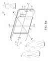
- FIG. 1Ais a front perspective view of an electronic apparatus in accordance with one exemplary implementation of the disclosed embodiments
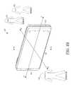
- FIG. 1Bis a rear perspective view of the electronic apparatus of FIG. 1A ;
- FIG. 2Ais a front view of the electronic apparatus of FIG. 1A ;
- FIG. 2Bis a rear view of the electronic apparatus of FIG. 1A ;
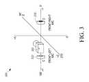
- FIG. 3is a schematic of a microphone and video camera configuration of an electronic apparatus in accordance with some of the disclosed embodiments
- FIG. 4is a block diagram of an exemplary system for delay and sum beamform processing of microphone output signals
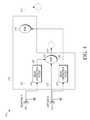
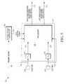
- FIG. 5is a block diagram of an audio processing system of an electronic apparatus in accordance with some of the disclosed embodiments.
- FIG. 6is a diagram that illustrates an exemplary polar graph of a right beamformed audio signal and an exemplary polar graph of a left beamformed audio signal with respect to an electronic apparatus and an angular field of view being acquired in accordance with one implementation of some of the disclosed embodiments;
- FIG. 7is a diagram that illustrates an exemplary polar graph of a right beamformed audio signal and an exemplary polar graph of a left beamformed audio signal that are generated by an electronic apparatus in accordance with another implementation of some of the disclosed embodiments;
- FIG. 8Ais an exemplary polar graph of a left-side-oriented beamformed signal generated by the audio processing system in accordance with one implementation of some of the disclosed embodiments;
- FIG. 8Bis an exemplary polar graph of a right-side-oriented beamformed signal generated by the audio processing system in accordance with one implementation of some of the disclosed embodiments;
- FIG. 8Cis an exemplary polar graph of a right-side-oriented beamformed signal generated by the audio processing system in accordance with another implementation of some of the disclosed embodiments;
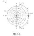
- FIG. 9Ais an exemplary polar graph of a right-side-oriented beamformed audio signal and a left-side-oriented beamformed audio signal generated by the audio processing system in accordance with one implementation of some of the disclosed embodiments;
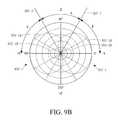
- FIG. 9Bis an exemplary polar graph of a right-side-oriented beamformed audio signal and a left-side-oriented beamformed audio signal generated by the audio processing system in accordance with another implementation of some of the disclosed embodiments;
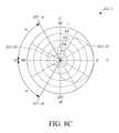
- FIG. 9Cis an exemplary polar graph of a right-side-oriented beamformed audio signal and a left-side-oriented beamformed audio signal generated by the audio processing system in accordance with yet another implementation of some of the disclosed embodiments.
- FIG. 10is a block diagram of an electronic apparatus that can be used in an implementation of the disclosed embodiments.
- the word “exemplary”means “serving as an example, instance, or illustration.”
- the following detailed descriptionis merely exemplary in nature and is not intended to limit the invention or the application and uses of the invention. Any embodiment described herein as “exemplary” is not necessarily to be construed as preferred or advantageous over other embodiments.
- All of the embodiments described in this Detailed Descriptionare exemplary embodiments provided to enable persons skilled in the art to make or use the invention and not to limit the scope of the invention which is defined by the claims. Furthermore, there is no intention to be bound by any expressed or implied theory presented in the preceding technical field, background, or the following detailed description.
- the embodimentsreside primarily in an electronic apparatus that has a front side and a rear side oriented in opposite directions along a first axis, and a right-side and a left-side oriented in opposite directions along a second axis that is perpendicular to the first axis.
- the electronic apparatusalso includes a first microphone located near the right-side of an electronic apparatus that generates a first signal, and a second microphone located near the left-side of the electronic apparatus that generates a second signal.
- a null control signalcan be generated based on an imaging signal.
- the first and second signalsare processed, based on the null control signal, to generate a right beamformed audio signal having a first directional pattern with at least one first null, and a left beamformed audio signal having a second directional pattern with at least one second null.
- nullrefers to a portion of a beamform where the magnitude is near-zero. Theoretically, a null exhibits no sensitivity to sound waves that emanate from angular directions incident on the angular location of the null.
- a first angular location ( ⁇ ) of the at least one first null and a second angular location ( ⁇ ) of the at least one second nullare steered based on the null control signal.
- the outputs of the microphonescan be processed to create opposing, virtual microphones with beamforms that have steerable nulls.
- the first and second directional patternscan remain diametrically opposed, but the angular locations of their respective nulls can be steered to a desired location for improved stereo imaging and/or for cancellation of an audio source at the rear-side of the electronic apparatus.
- FIG. 1Ais a front perspective view of an electronic apparatus 100 in accordance with one exemplary implementation of the disclosed embodiments.
- FIG. 1Bis a rear perspective view of the electronic apparatus 100 .
- the perspective view in FIGS. 1A and 1Bare illustrated with reference to an operator 140 of the electronic apparatus 100 that is recording one or more subjects 150 , 160 .
- FIG. 2Ais a front view of the electronic apparatus 100 and FIG. 2B is a rear view of the electronic apparatus 100 .
- the electronic apparatus 100can be any type of electronic apparatus having multimedia recording capability.
- the electronic apparatus 100can be any type of portable electronic device with audio/video recording capability including a camcorder, a still camera, a personal media recorder and player, or a portable wireless computing device.
- the term “wireless computing device”refers to any portable computer or other hardware designed to communicate with an infrastructure device over an air interface through a wireless channel.
- a wireless computing deviceis “portable” and potentially mobile or “nomadic” meaning that the wireless computing device can physically move around, but at any given time may be mobile or stationary.
- a wireless computing devicecan be one of any of a number of types of mobile computing devices, which include without limitation, mobile stations (e.g. cellular telephone handsets, mobile radios, mobile computers, hand-held or laptop devices and personal computers, personal digital assistants (PDAs), or the like), access terminals, subscriber stations, user equipment, or any other devices configured to communicate via wireless communications.
- mobile stationse.g. cellular telephone handsets, mobile radios,
- the electronic apparatus 100has a housing 102 , 104 , a left-side portion 101 , and a right-side portion 103 opposite the left-side portion 101 .
- the housing 102 , 104has a width dimension extending in a y-direction, a length dimension extending in an x-direction, and a thickness dimension extending in a z-direction (into and out of the page).
- the electronic apparatus 100has a front-side (illustrated in FIG. 2A ) and a rear-side (illustrated in FIG. 2B ) oriented in opposite directions along a first axis. The rear-side is oriented in a +z-direction and the front-side oriented in a ⁇ z-direction.
- the left-side portion 101 and the right-side portion 103are oriented in opposite directions along a y-axis that is perpendicular to the z-axis.
- the designations of “right”, “left”, “width”, and “length”may be changed. The current designations are given for the sake of convenience.
- the housingincludes a rear housing 102 on the operator-side or rear-side of the apparatus 100 , and a front housing 104 on the subject-side or front-side of the apparatus 100 .
- the rear housing 102 and front housing 104are assembled to form an enclosure for various components including a circuit board (not illustrated), a speaker (not illustrated), an antenna (not illustrated), a video camera 110 , and a user interface including microphones 120 , 130 that are coupled to the circuit board.
- Microphone 120is located nearer the left-side 101
- microphone 130is located nearer the right-side 103 .
- the housingincludes a plurality of ports for the video camera 110 and the microphones 120 , 130 .
- the front housing 104has ports for the front-side video camera 110 and other ports for the front-side microphones 120 , 130 .
- the microphones 120 , 130are disposed at/near these ports, and in some implementations the y-axis goes through the two microphone port openings.
- the video camera 110is positioned on the front-side and thus oriented in the same direction as the front housing 104 , opposite the operator, to allow for images of the subject(s) to be acquired or captured during recording by the video camera 110 .
- the left-side portion 101is defined by and shared between the rear housing 102 and the front housing 104 , and oriented in a +y-direction that is substantially perpendicular with respect to the rear housing 102 and the front housing 104 .
- the right-side portion 103is opposite the left-side portion 101 , and is defined by and shared between the rear housing 102 and the front housing 104 .
- the right-side portion 103is oriented in a ⁇ y-direction that is substantially perpendicular with respect to the rear housing 102 and the front housing 104 .
- FIG. 3is a schematic of a microphone and video camera configuration 300 of the electronic apparatus in accordance with some of the disclosed embodiments.
- the configuration 300is illustrated with reference to a Cartesian coordinate system and includes the relative locations of a left-side microphone 320 with respect to a right-side microphone 330 and video camera 310 .
- Both physical microphone elements 320 , 330are shown on the subject or front-side of the electronic apparatus 100 , but could reside on left and right sides 101 , 103 respectively.
- the left-side microphone 320is disposed near the left-side of the electronic apparatus and the right-side microphone 330 is disposed near a right-side of the electronic apparatus 100 .
- the video camera 310is shown positioned on a front-side of the electronic apparatus 100 and disposed near the left-side of the electronic apparatus 100 , but could be disposed anywhere on the front side of the electronic apparatus 100 .
- the video camera 310could be disposed on the rear-side of the electronic apparatus 100 or a second camera (not shown) could be disposed on the rear-side of the electronic apparatus 100 to capture images or video of the operator 140 of the electronic apparatus 100 (e.g., in a webcam configuration).
- the left-side and right-side microphones 320 , 330are located or oriented opposite each other along a common y-axis, which is oriented along a line at zero and 180 degrees.
- the z-axisis oriented along a line at 90 and 270 degrees and the x-axis is oriented perpendicular to the y-axis and the z-axis in an upward direction.
- the left-side and right-side microphones 320 , 330are separated by 180 degrees along the y-axis or diametrically opposed with respect to each other.
- the camera 310is also located along the y-axis and points into the page in the ⁇ z-direction towards the subject(s) who are located in front of the apparatus 100 . This way the left-side and right-side microphones 320 , 330 are oriented such that they can capture audio signals or sound from the operator taking the video and as well as from the subjects being recorded by the video camera 310 .
- the left-side and right-side microphones 320 , 330can be any known type of microphone elements including omnidirectional microphones and directional microphones, pressure microphones, pressure gradient microphones or any other equivalent acoustic-to-electric transducer or sensor that converts sound into an electrical audio signal, etc.
- the left-side and right-side microphones 320 , 330are pressure microphone elements, they will have omnidirectional polar patterns that sense/capture incoming sound more or less equally from all directions.
- the left-side and right-side microphones 320 , 330can be part of a microphone array that is processed using beamforming techniques, such as delaying and summing (or delaying and differencing), to establish directional patterns based on electrical audio signals generated by the left-side and right-side microphones 320 , 330 .
- the delaycan either be a phase delay distinct at every frequency implemented via a filter, or a fixed time delay.
- delay and sum beamform processingwill now be described with reference to FIG. 4 .
- FIG. 4is a block diagram of an exemplary system 400 for delay and sum beamform processing of microphone output signals 422 , 412 .
- Concepts illustrated in this systemcan be used in accordance with some of the disclosed embodiments.
- the system 400includes a microphone array that includes left and right microphones 320 , 330 and a beamformer module 450 .
- Each of the microphones 330 , 320generates an electrical audio signal 412 , 422 in response to incoming sound.
- These electrical audio signals 412 , 422are generally a voltage signal that corresponds to sound captured at the left and right microphones 330 , 320 .
- the beamformer module 450is designed to generate right and left beamformed signals 452 , 454 .
- the beamformer module 450includes a first correction filter 414 , a second correction filter 424 , a first summer module 428 , and a second summer module 429 .
- the first correction filter 414adds phase delay to the first electrical audio signal 412 to generate a first delayed signal 416
- the second correction filter 424adds phase delay to the second electrical audio signal 422 to generate a second delayed signal 426 .
- the correction filters 414 , 424add a phase delay to the corresponding electrical audio signals 412 , 422 to generate the corresponding delayed signals 416 , 426 .
- the first summer module 428sums the first signal 412 and the second delayed signal 426 to generate a first beamformed signal 452 .
- the second summer module 429sums the second signal 422 and the first delayed signal 416 to generate a second beamformed signal 454 .
- the first beamformed signal 452is a right-facing first-order directional signal (e.g., supercardioid or hypercardioid) that corresponds to a right channel stereo output with a beampattern that is oriented to the right-side or in the ⁇ y-direction.
- the second beamformed signal 454is a left-facing first-order directional signal (e.g., supercardioid or hypercardioid) that corresponds to a left channel stereo output with a beampattern that is oriented to the left-side or in the +y-direction.
- the left channel stereo outputis spatially distinct from the right channel stereo output.
- the first beamformed signal 452corresponds to a right-facing virtual directional microphone with a main lobe having a maximum located along the 0 degree axis
- the second beamformed signal 454corresponds to a left-facing virtual directional microphone with a main lobe having a maximum located along the 180 degree axis.
- each of the beamformed audio signals 452 , 454is shown as separate right and left output channels, in some embodiments, these signals 452 , 454 can be combined into a single audio output data-stream that can be transmitted and/or recorded as a single file containing separate stereo coded signals, but do not necessarily have to be combined.
- the beamformed signals 452 , 454 shown in FIG. 4are both beamformed first order hypercardioid directional beamform patterns that are either right-side-oriented or left-side-oriented, those skilled in the art will appreciate that the beamformed signals 452 , 454 are not necessarily limited to having these particular types of first order hypercardioid directional patterns and that they are shown to illustrate one exemplary implementation.
- the directional patternsare hypercardioid-shaped, this does not necessarily imply the beamformed signals are limited to having a hypercardioid shape, and may have any other shape that is associated with first order directional beamform patterns such as a cardioid, dipole, supercardioid, etc.
- the beamformed signals 452 , 454are illustrated as having hypercardioid directional patterns, it will be appreciated by those skilled in the art, that these are mathematically ideal examples only and that, in some practical implementations, these idealized beamform patterns will not necessarily be achieved.
- the first order beamformsare those which follow the form A+B cos ( ⁇ ) in their directional characteristics.
- all first order directional microphoneshave a polar response described by equation (1): (A+B cos ⁇ )/(A+B) (1),
- any first order elementcan be created oriented along the axis of the bidirectional element.
- the directional patterns that can be produced by beamformingcan range from a nearly cardioid beamform to a nearly bidirectional beamform, or from a nearly cardioid beamform to a nearly omnidirectional beamform.
- For an omnidirectional microphone Bis 0; and for a bidirectional microphone A is zero.
- first order directional patternswhere A ⁇ B result in patterns with higher directivity, and two nulls symmetric about the axis of the microphone wherein the axis of the microphone is defined as the angle of the peak of the main lobe of the beampattern through its 180-degree opposite.
- the nullsare collocated as one single null which is at an angle of 0 degrees to the axis (and opposite the peak).
- a linear combination of properly phased omnidirectional and bidirectional microphone signalswill produce the desired first order directional microphone pattern.
- FIG. 5is a block diagram of an audio processing system 500 of an electronic apparatus 100 in accordance with some of the disclosed embodiments.
- the audio processing system 500includes a microphone array that includes a first or left microphone 520 that generates a first signal 521 in response to incoming sound, and a second or right microphone 530 that generates a second signal 531 in response to the incoming sound.
- These electrical signalsare generally a voltage signal that corresponds to a sound pressure captured at the microphones.
- a first filtering module 522is designed to filter the first signal 521 to generate a first phase-delayed audio signal 525 (e.g., a phase delayed version of the first signal 521 ), and a second filtering module 532 is designed to filter the second signal 531 to generate a second phase-delayed audio signal 535 .
- the first filtering module 522 and the second filtering module 532are illustrated as being separate from processor 550 , it is noted that in other implementations the first filtering module 522 and the second filtering module 532 can be implemented within the processor 550 as indicated by the dashed-line rectangle 540 .
- the automated null controller 560generates a null control signal 565 based on an imaging signal 585 .
- the imaging signal 585can be provided from any one of number of different sources, as will be described in greater detail below.
- the sources that can provide the imaging signalcan include a video camera, a controller for the video camera, or proximity sensors.
- the processor 550is coupled to the first microphone 520 , the second microphone 530 , and the automated null controller 560 , and receives a plurality of input signals including the first signal 521 , the first phase-delayed audio signal 525 , the second signal 531 , the second phase-delayed audio signal 535 , and the null control signal 565 .
- the processor 550performs beamform processing.
- the beamform processing performed by the processor 550can generally include delay and sum processing (as described above with reference to FIG. 4 , for example), delay and difference processing, or any other known beamform processing technique for generating directional patterns based on microphone input signals. Techniques for generating such first order beamforms are well-known in the art, and will not be described further herein.
- the null control signal 565can be used by the processor 550 to control or steer nulls of the right-side-oriented beamformed audio signal 552 and the left-side-oriented beamformed audio signal 554 during beamform processing.
- the processor 550processes the input signals 521 , 525 , 531 , 535 , based on the null control signal 565 , to generate a right (or “right-side-oriented”) beamformed audio signal 552 that has a first directional pattern having at least one “first” null, and a left (or “left-side-oriented”) beamformed audio signal 554 that has a second directional pattern having at least one “second” null, where a first angular location ( ⁇ ) of the at least one first null and a second angular location ( ⁇ ) of the at least one second null is steered based on the null control signal 565 .
- the first angular location ( ⁇ )is at a first angle with respect to the +y-axis
- the second angular location ( ⁇ )is at a second angle with respect to the ⁇ y-axis.
- the values of the first and second angular locationscan be the same or different.
- the directional patternscan be first-order directional patterns as described above with reference to FIG. 4 .
- the null control signal 565can be used to control or “steer” the first angular location ( ⁇ ) of the first null of the right-side-oriented beamformed audio signal 552 and the second angular location ( ⁇ ) of the second null of the left-side-oriented beamformed audio signal 554 . As will be explained further below, this allows for control of the sensitivity of subject-oriented virtual microphones as well as for steering of the nulls of those virtual microphones.
- the nulls of the beamformed audio signals 552 , 554may include more than one null point.
- the right beamformed audio signal 552can include a first null point oriented towards the front-side 104 at an angular location + ⁇ and a second null point oriented toward the rear-side 102 at an angular location ⁇
- the left beamformed audio signal 554can include a third null point oriented towards the front-side 104 at an angular location + ⁇ and a fourth null point oriented toward the rear-side 102 at an angular location ⁇ , respectively.
- the processor 550can include a look up table (LUT) that receives the input signals and the null control signal 565 , and generates the right beamformed audio signal 552 and the left beamformed audio signal 554 .
- the LUTis table of values that generates different signals 552 , 554 depending on the value of the null control signal 565 .
- the processor 550is designed to process a set of equations based on the input signals 521 , 525 , 531 , 535 and the null control signal 565 to generate the right beamformed audio signal 552 and the left beamformed audio signal 554 .
- the equationsinclude coefficients for the first signal 521 , the first phase-delayed audio signal 525 , the second signal 531 , and the second phase-delayed audio signal 535 ; and the values of these coefficients can be adjusted or controlled based on the null control signal 565 to generate the right beamformed audio signal 552 and/or the left beamformed audio signal 554 with nulls steered to the desired angular locations (+ ⁇ , ⁇ , + ⁇ , ⁇ ).
- imaging signals 585that can be used to generate the null control signal 565 will now be described in greater detail for various implementations.
- the imaging signal 585 used to determine or generate the null control signal 565can vary depending on the implementation.
- the automated null controller 560can be coupled to the video camera 310 that provides the imaging signal 585 .
- the automated null controller 560is coupled to a video controller that is coupled to the video camera 310 and provides the imaging signal 585 to the automated null controller 560 .
- the imaging signal 585 that is used by the automated null controller 560 to generate the null control signal 565can be (or can be determined based on) one or more of (a) an angular field of view of a video frame of the video camera 310 , (b) a focal distance for the video camera 310 , or (c) a zoom control signal for the video camera 310 . Any of these parameters can be used alone or in combination with the others to generate a null control signal 565 .
- the video controller that generates the imaging signal 585can be implemented in hardware or software. It may be an automated controller or one driven by user input such as a button, slider, navigation control, any other touch controller, or a graphical user interface (GUI).
- GUIgraphical user interface
- the imaging signal 585is based on focal distance for the video camera 310 .
- focal distance information from the camera 310 to the subjects 150 , 160can be obtained from the camera 310 , a video controller for the video camera 310 , or any other distance determination circuitry in the device.
- focal distance of the video camera 310can be used by the automated null controller 560 to generate the null control signal 565 .
- the null control signal 565can be a calculated focal distance of the video camera 110 that is sent to the automated null controller 560 by a video controller.
- the first angular location ( ⁇ ) and the second angular location ( ⁇ )increase relative to the y-axis as the focal distance is increased.
- the first angular location ( ⁇ ) and the second angular location ( ⁇ )decrease relative to the y-axis as the focal distance is decreased.
- the first angular location ( ⁇ ) and the second angular location ( ⁇ )can be determined from a lookup table for a particular value of the focal distance. In another implementation, the first angular location ( ⁇ ) and the second angular location ( ⁇ ) can be determined from a function relating the focal distance to the null angles.
- the imaging signal 585can be based on an angular field of view (FOV) of a video frame of the video camera 310 .
- FOVangular field of view
- the angular field of view of the video frame of the video camera 310can be calculated and sent to the automated null controller 560 , which can then use that information to generate the null control signal 565 .
- the first angular location ( ⁇ ) and the second angular location ( ⁇ )increase relative to the y-axis as the angular field of view is narrowed or decreased.
- the first angular location ( ⁇ ) and the second angular location ( ⁇ )decrease relative to the y-axis as the angular field of view is widened or increased.
- the first angular location ( ⁇ ) and the second angular location ( ⁇ )can be determined from a lookup table for a particular value of the field of view. In another implementation, the first angular location ( ⁇ ) and the second angular location ( ⁇ ) can be determined from a function relating the field of view to the null angles.
- the imaging signal 585is based on a zoom control signal for the video camera 310 .
- the physical video zoom of the video camera 310is used to generate the null control signal 565 .
- a narrow zoomcan also be called a high zoom value, whereas a wide zoom can also be called a low zoom value.
- the zoom control signalis increased to narrow the angular field of view, this will cause the first angular location ( ⁇ ) and the second angular location ( ⁇ ) to increase relative to the y-axis which goes through the left and right microphones 320 , 330 .
- the null control signal 565can be a zoom control signal for the video camera 310 , whereas in other embodiments the null control signal 565 can be derived based on a zoom control signal for the video camera 310 .
- the zoom control signal for the video camera 310can be a digital zoom control signal that controls an apparent angle of view of the video camera, whereas in other implementations the zoom control signal for the video camera 310 can be an optical/analog zoom control signal that controls position of lenses in the camera.
- preset null angle valuescan be assigned for particular values (or ranges of values) of the zoom control signal.
- the zoom control signal for the video cameracan be controlled by a user interface (UI).
- UIuser interface
- Any known video zoom UI methodologycan be used to generate a zoom control signal.
- the video zoomcan be controlled by the operator via a pair of buttons, a rocker control, virtual controls on the display of the device including a dragged selection of an area, by eye tracking of the operator, etc.
- the first angular location ( ⁇ ) and the second angular location ( ⁇ )can be determined from a lookup table for a particular value of the zoom control signal. In another implementation, the first angular location ( ⁇ ) and the second angular location ( ⁇ ) can be determined from a function relating the value of a zoom control signal to field of view.
- the imaging signal 585can include proximity information generated by the proximity detector or sensor.
- the apparatus 100can include a rear-side proximity sensor that is coupled to the automated null controller 560 .
- the rear-side proximity sensorgenerates a rear-side proximity sensor signal that corresponds to a distance between the camera operator 140 and the apparatus 100 .
- the rear-side proximity sensor signalcan then be sent to the automated null controller 560 , which can use the rear-side proximity sensor signal to generate the null control signal 565 .
- the rear-side proximity sensor signalcorresponds to a distance between the camera operator 140 and the apparatus 100 .
- the rear-side proximity sensor signalcan be based on estimated, measured, or sensed distance between the camera operator 140 and the electronic apparatus 100 .
- the rear-side proximity sensor signalcorresponds to a predetermined distance between the camera operator 140 and the apparatus 100 .
- the predetermined distancecan be set as a fixed distance at which an operator of the camera 110 is normally located (e.g., based on an average human holding the device in a predicted usage mode).
- the automated null controller 560presumes that the camera operator is a predetermined distance away from the apparatus and generates a null control signal 565 to reflect that predetermined distance.
- the rear-side proximity sensor signalcorresponds to a distance between the camera operator and the apparatus 100
- the second null point (of the right beamformed audio signal 552 ) and the fourth null point (of the left beamformed audio signal 554 )are oriented to cancel sound that originates from the rear-side at the distance.
- thisallows the coverage angle of the nulls to be oriented such that a sound source behind the apparatus 100 (e.g., such as the operator) can be suppressed.
- FIG. 6is a diagram that illustrates an exemplary polar graph of a right beamformed audio signal 652 and an exemplary polar graph of a left beamformed audio signal 654 with respect to an electronic apparatus 600 and an angular field of view being acquired in accordance with one implementation of some of the disclosed embodiments.
- the electronic apparatus 600is not drawn to scale, and is exaggerated in size to illustrate its relationship to a field of view 650 being acquired or recorded by a video camera (not shown) of the electronic apparatus 600 .
- the field of view 650 being acquired or recorded by the video camera (not shown)is much larger than the apparatus 600 such that the apparatus is effectively a point receptor with respect to the field of view 650 .
- FIG. 6is a diagram that illustrates an exemplary polar graph of a right beamformed audio signal 652 and an exemplary polar graph of a left beamformed audio signal 654 with respect to an electronic apparatus 600 and an angular field of view being acquired in accordance with one implementation of some of the disclosed embodiments.
- the desired recordingwould be for (a) the audio from the right side of the stage to be recorded on the right channel, (b) the audio from the left side of the stage recorded to the left channel, and (c) to have objects in the middle appear on both channels to give a center audio image for those objects.
- Output signals 521 , 531 generated by the physical microphones 520 , 530are processed using the beamforming techniques described above to generate the right beamformed audio signal 652 that has a first super-cardioid directional pattern that is oriented to the right in the direction of the ⁇ y-axis, and the left beamformed audio signal 654 that has a second super-cardioid directional pattern that is oriented to the left in the direction of the +y-axis.
- the major lobes of the first super-cardioid directional pattern and the second super-cardioid directional patternare oriented diametrically opposite each other to the right and left, respectively. Further details regarding the 654 and 652 will be described below with reference to FIGS. 8A and 8B , respectively.
- the field of view 650 of the video frameis split into a left-side portion and a right-side portion via a center line 651 .
- the left-side portioncontributes to a desired left audio image 625
- the right-side portioncontributes to a desired right audio image 645 .
- the first super-cardioid directional pattern of the right beamformed audio signal 652produces a right channel null region 635
- the second super-cardioid directional pattern of the left beamformed audio signal 654produces a left channel null region 655 .
- the desired left audio image 625overlaps the right channel null region 635 (as illustrated by a rectangular shaded region) that is associated with the right beamformed audio signal 652 but does not include the left channel null region 655 (as illustrated by a rectangular shaded region), and the desired right audio image 645 overlaps the left channel null region 655 that is associated with the left beamformed audio signal 654 but does not include the right channel null region 635 .
- the first angular location ( ⁇ ) of the first nullis defined between two null lines 636 , 638 that diverge from a common origin to define a right channel null region 635 .
- a first null center line 637is defined between the null region boundaries 636 , 638 , and has a first angular location ( ⁇ ) with respect to the +y-axis.
- the right channel null region 635is a null region that is centered around the first null center line 637 and bounded by the null region boundaries 636 , 638 .
- the angle that the null region 635 spansis a first number of degrees equal to 2 ⁇ .
- the term “null center line”refers to a line going through a null of a beamform at a point where the magnitude of the beamform is at its minimum.
- the angle of the two null region boundaries 636 , 638also changes along with the right channel null region 635 .
- the second angular location ( ⁇ ) of the second nullis defined between two null region boundaries 656 , 658 that diverge from a common origin to define a left channel null region 655 .
- the left channel null region 655also spans a second number of degrees equal to 2 ⁇ , which may be equal to the first number of degrees 2 ⁇ .
- a null center line 657is defined between the null region boundaries 656 , 658 , and has the second angular location ( ⁇ ) with respect to the ⁇ y-axis.
- the left channel null region 655is a null region that is centered around the second null center line 657 . As the second angular location ( ⁇ ) changes, the angle of the two null region boundaries 656 , 658 also changes along with the left channel null region 655 .
- each channel's null regionsare located approximately three-quarters of the way across the image field from a desired edge of field for that channel, and at approximately the center of the opposite side of the field being acquired.
- the directional pattern of the right beamformed audio signal 652will have stronger sensitivity to sound waves originating from the region that corresponds to the desired right audio image 645 , but significantly lessened sensitivity to sound waves originating from the region that corresponds to the desired left audio image 625 .
- the right channel null region 635coincides with the desired left audio image 625 and allows some of sound originating from the desired left audio image 625 to be reduced.
- the virtual microphone corresponding to the right beamformed audio signal 652can be used to acquire/record a desired right audio image 645 , with minimal signal being acquired from the left audio image 625 due to the right channel null region 635 .
- the right channel null of the beamformis centered on the left side of the stage.
- the signal that will be recorded on the right channelwill include a full audio level for the subjects furthest to the right, with a general decline in audio level moving towards center, and with a significant suppression of the audio at the center of the left side of the stage where the shaded rectangle is shown.
- the directional pattern of the left beamformed audio signal 654will have stronger sensitivity to sound waves originating from the region that corresponds to the desired left audio image 625 , but significantly lessened sensitivity to sound waves originating from the region that corresponds to the desired right audio image 645 .
- the left channel null region 655coincides with the desired right audio image 645 and allows some of sound originating from the desired right audio image 645 to be reduced.
- the virtual microphone corresponding to the left beamformed audio signal 654can be used to acquire/record a desired left audio channel 625 , with minimal signal being acquired from the right audio image 645 due to the left channel null region 655 .
- the left channel null of the beamformis centered on the right-side.
- the signal that will be recorded on the left channelwill include a full audio level for the subjects furthest to the left, with a general decline in audio level moving towards center, and with a significant suppression of the audio at the center of the right side of the stage where the shaded rectangle is shown.
- the right beamformed audio signal 652 and the left beamformed audio signal 654can ultimately be combined to produce a stereo signal with appropriate imaging contributions from the desired left audio channel 625 and the desired right audio channel 645 of the subject(s) being acquired.
- the first angular location ( ⁇ ) of the right channel null region 635 and the second angular location ( ⁇ ) of the left channel null region 655can be steered based on the null control signal 565 during beamform processing.
- the null control signal 565can be used to control or “steer” the first angular location ( ⁇ ) of the right channel null region 635 of the right-side-oriented beamformed audio signal 652 and the second angular location ( ⁇ ) of the left channel null region 655 of the left-side-oriented beamformed audio signal 654 .
- angular locations ( ⁇ , ⁇ ) of the right channel null region 635 and the left channel null region 655can be steered based on an angular field of view, a focal distance, or a zoom control signal, for example, to vary the stereo imaging and make the stereo signal coincide with the video frame that is being acquired/captured by the operator.
- the angles or angular locations ( ⁇ , ⁇ ) of the right channel null region 635 and the left channel null region 655can be steered to de-emphasize sound waves that originate from directions corresponding to different null regions with respect to the field of view 650 being acquired by the electronic apparatus 600 .
- the positions of the right channel null region 635 and the left channel null region 655can be changed or controlled via the null control signal. For example, as the first angular location ( ⁇ ) of the right channel null region 635 decreases (e.g., by decreasing a zoom control signal), the right channel null region 635 will move further away from the center line 651 and the audio field of view will widen.
- FIG. 7is a diagram that illustrates an exemplary polar graph of a right beamformed audio signal 752 and an exemplary polar graph of a left beamformed audio signal 754 that are generated by an electronic apparatus 700 in accordance with another implementation of some of the disclosed embodiments.
- This viewdiffers from that in FIG. 6 in that it shows the angular locations ( ⁇ , ⁇ ) of the right channel null region 735 and the left channel null region 755 with respect to an operator 740 of the electronic apparatus 700 , where the angular locations ( ⁇ , ⁇ ) of the right channel null region 735 and the left channel null region 755 of virtual microphones have been steered for cancellation of sound waves that originate from the rear-side of the electronic apparatus 700 (e.g., from the operator 740 ).
- the nulls of the beamformed audio signals 752 , 754may include more than one null region.
- the right beamformed audio signal 752can include a first null point (corresponding to line 737 ) oriented towards the front-side 704 and a second null point (corresponding to line 741 ) oriented toward the rear-side 702
- the left beamformed audio signal 754can include a third null point (corresponding to line 757 ) oriented towards the front-side 704 and a fourth null point (corresponding to line 760 ) oriented toward the rear-side 702 , respectively.
- a rear-side proximity sensorcoupled to the automated null controller, generates a rear-side proximity sensor signal that corresponds to a predetermined distance between a camera operator and the apparatus.
- the imaging signalis also based on the rear-side proximity sensor signal.
- the nulls on the operator side of the apparatus 700can be computed such that a ratio of A and B (in equation (1)) are selected such that the null from each side is pointed at the operator controlling the apparatus 700 .
- the anglecan be computed based on the average position that is it assumed the operator is going to be behind the device based on human factors studies or user testing.
- the anglecan be computed from half the distance between the microphones and the measured distance to the operator. The angle would be computed using a function such as ARCTAN ((micspacing/2)/distance).
- a rear-side proximity sensor(not shown) can generate a rear-side proximity sensor signal that corresponds to a distance between a camera operator 740 and the apparatus 700 .
- the automated null controllercan use the rear-side proximity sensor signal to generate a null control signal such that the second null point (corresponding to line 741 ) and the fourth null point (corresponding to line 760 ) are steered such that they are oriented to cancel sound that originates from the rear-side 702 at the proximity-sensed distance of the operator thus reducing or canceling sound that originates from the camera operator 740 or other proximity-sensed rear-side sound source.
- Rear-side cancellationis a separate mode and is not based on the optical frame being acquired.
- FIGS. 8A-9CExamples of beamformed signals generated by the processor 550 and null steering of those signals will be described below with reference to polar graphs illustrated in FIGS. 8A-9C .
- signal magnitudesare plotted linearly to show the directional or angular response of a particular signal.
- the subjectis generally centered at approximately 90° while the operator is located at approximately 270°.
- the directional patterns shown in FIGS. 8A-9Care slices through the directional response forming a plane as would be observed by a viewer who, located above the electronic apparatus 100 of FIGS.
- FIG. 1A and 1Bis looking downward, where the z-axis in FIG. 3 corresponds to the 90°-270° line, and the y-axis in FIG. 3 corresponds to the 0°-180° line through the microphone port openings.
- the complete directional patternsare three-dimensional and planar slices are provided here for the sake of simplicity.
- a particular null regionis represented here only by its corresponding null center line.
- FIG. 8Ais an exemplary polar graph of a left-side-oriented beamformed signal 854 generated by the audio processing system 500 in accordance with one implementation of some of the disclosed embodiments.
- the left-side-oriented beamformed signal 854 of FIG. 8Ais representative of the left-side-oriented beamformed signals 654 , 754 shown in FIGS. 6 and 7 .
- the left-side-oriented beamformed signal 854has a first-order directional pattern that points or is oriented towards the +y-direction, and has a main lobe 854 -A having a maximum at 180 degrees and a minor lobe 854 -B that is oriented in the ⁇ y-direction.
- This directional patternindicates that there is a stronger directional sensitivity to sound waves traveling towards the left-side of the apparatus 100 .
- the left-side-oriented beamformed signal 854also has a pair of nulls that are centered at null center lines 857 -A, 857 -B.
- the null center line 857 -A of one nullpoints at an angular location ( ⁇ ) towards the front right-side of the apparatus 100 and corresponds to a front-left channel null region (see FIG. 6 ).
- the other null center line 857 -B of the other nullpoints at an angle or angular location ( ⁇ ) towards the rear right-side of the apparatus 100 and corresponds to a rear-left channel null region (see FIG. 7 ).
- the angular location ( ⁇ ) of the null center line 857 -Ais at approximately 75 degrees with respect to the ⁇ y-axis
- the angular location ( ⁇ ) of the null center line 857 -Bis at approximately ⁇ 75 degrees with respect to the ⁇ y-axis.
- FIG. 8Bis an exemplary polar graph of a right-side-oriented beamformed signal 852 generated by the audio processing system 500 in accordance with one implementation of some of the disclosed embodiments.
- the right-side-oriented beamformed signal 852 of FIG. 8Bis representative of the right-side-oriented beamformed signals 652 , 752 shown in FIGS. 6 and 7 .
- the right-side-oriented beamformed signal 852has a first-order directional pattern that points or is oriented towards the right in the ⁇ y-direction, and has a main lobe 852 -A having a maximum at zero degrees and a minor lobe 852 -B that is oriented in the +y-direction.
- This directional patternindicates that there is a stronger directional sensitivity to sound waves traveling towards the right-side of the apparatus 100 .
- the right-side-oriented beamformed signal 852also has a pair of nulls that are centered at null center lines 837 -A, 837 -B.
- the null center line 837 -A of one nullpoints at an angular location ( ⁇ ) towards the front left-side of the apparatus 100 and corresponds to a front-right channel null region (see FIG. 6 ).
- the other null center line 837 -B of the other nullpoints at an angular location ( ⁇ ) towards the rear left-side of the apparatus 100 and corresponds to a rear-right channel null region (see FIG. 7 ).
- the angular location ( ⁇ ) of the null center line 837 -Ais at approximately ⁇ 75 degrees with respect to the +y-axis
- the angular location ( ⁇ ) of the null center line 837 -Bis at approximately +75 degrees with respect to the +y-axis.
- the automated null controller 560generates a null control signal 565 that can be used by the processor 550 to control or steer nulls of the right-side-oriented beamformed audio signal 552 and the left-side-oriented beamformed audio signal 554 during beamform processing to change the angular locations of the nulls.
- a null control signal 565can be used by the processor 550 to control or steer nulls of the right-side-oriented beamformed audio signal 552 and the left-side-oriented beamformed audio signal 554 during beamform processing to change the angular locations of the nulls.
- FIG. 8Cis an exemplary polar graph of a right-side-oriented beamformed signal 852 generated by the audio processing system 500 in accordance with another implementation of some of the disclosed embodiments.
- the right-side-oriented beamformed signal 852has a first-order directional pattern similar to that illustrated in FIG. 8B .
- an angular location of the nulls of the right-side-oriented beamformed signal 852has changed.
- the null center line 837 - 1 Anow has an angular location ⁇ of approximately ⁇ 60 degrees with respect to the +y-axis
- the null center line 837 - 1 Bnow has an angular location ⁇ of approximately +60 degrees) with respect to the +y-axis.
- the angular location of the nulls(as represented by their respective null center lines 837 - 1 A, 837 - 1 B) have been steered to point at different angular locations in FIG. 8C (even though the null center lines still remain oriented at angles towards the front left-side and the rear left-side of the apparatus 100 , respectively, and the main lobe still has its maximum located at 0 degrees).
- the relative locations of the front-right channel null region (not illustrated) and the rear-right channel null region (not illustrated)will also change the location of the right audio image further to the right.
- the magnitude of the main lobe 852 - 1 Ahas increased relative to the magnitude of the minor lobe 852 - 1 B resulting in the audio image shifting further to the right.
- the angular location of the main lobe 852 - 1 Aremains fixed at zero degrees.
- the beamformed audio signals 852 , 854can be combined into a single audio output data stream that can be transmitted and/or recorded as a file containing separate stereo coded signals.
- FIGS. 9A-9Cwill illustrate some examples of such a combination by describing different examples of beamformed signals 552 , 554 that can be generated by the processor 550 in different scenarios.
- both the responses of a right-side-oriented beamformed audio signal 952 and a left-side-oriented beamformed audio signal 954will be shown together to illustrate that the signals may be combined in some implementations to achieve stereo effect.
- FIG. 9Ais an exemplary polar graph of a right-side-oriented beamformed audio signal 952 and a left-side-oriented beamformed audio signal 954 generated by the audio processing system 500 in accordance with one implementation of some of the disclosed embodiments.
- the right-side-oriented beamformed audio signal 952has a first-order directional pattern with a major lobe 952 -A that is oriented towards or points in the ⁇ y-direction.
- This first-order directional patternhas a maximum at 0 degrees and has a relatively strong directional sensitivity to sound waves traveling towards the right-side of the apparatus 100 .
- the right-side-oriented beamformed audio signal 952also has a first null with a null center line 937 at approximately 150 degrees, or at an angle of approximately 30 degrees with respect to the +y-axis.
- the first nullpoints towards the left-front-side of the apparatus 100 , which indicates that there is little or no directional sensitivity to sound waves traveling towards the apparatus 100 that originate from the front-left of the apparatus 100 .
- the first angular location ( ⁇ ) of the first nullcorresponds to the first null center line 937 that corresponds to a right channel null region.
- the left-side-oriented beamformed audio signal 954also has a first-order directional pattern with a major lobe 954 -A that is oriented in the +y-axis, and has a maximum at 180 degrees. This indicates that there is strong directional sensitivity to sound waves traveling towards the left-side of the apparatus 100 .
- the left-side-oriented beamformed audio signal 954also has a second null with a null center line at approximately 30 degrees.
- the second null center line 957is at an angle of approximately 30 degrees with respect to the ⁇ y-axis.
- the second nullpoints towards the front-right-side of the apparatus 100 , which indicates that there is little or no directional sensitivity to sound waves traveling towards the apparatus 100 that originate from the front-right of the apparatus 100 .
- the second angular location ( ⁇ ) of the second nullcorresponds to the second null center line 957 that corresponds to a left channel null region.
- the sum of the first angular location ( ⁇ ) and the second angular location ( ⁇ )will be equal to the difference between 180 degrees and a spacing or separation angle ( ⁇ ) that represents the angular spacing between the second null center line 957 and the first null center line 937 .
- null settings in FIG. 9Acould be used, for example, when a relatively wide the field of view is desired by decreasing a zoom control signal to steer the nulls to the specified locations.
- FIG. 9Bis an exemplary polar graph of a right-side-oriented beamformed audio signal 952 - 1 and a left-side-oriented beamformed audio signal 954 - 1 generated by the audio processing system 500 in accordance with another implementation of some of the disclosed embodiments.
- the right-side-oriented beamformed audio signal 952 - 1has a first-order directional pattern with a major lobe 952 - 1 A that is oriented towards or points in the ⁇ y-direction.
- This first-order directional patternhas a maximum at 0 degrees and has a relatively strong directional sensitivity to sound waves traveling towards the right-side of the apparatus 100 .
- the right-side-oriented beamformed audio signal 952 - 1also has a first null with a null center line 937 - 1 at approximately 120 degrees.
- the first null center line 937 - 1is thus at an angle of approximately 60 degrees with respect to the +y-axis.
- the first nullpoints towards the left-front-side of the apparatus 100 , which indicates that there is little or no directional sensitivity to sound waves traveling towards the apparatus 100 that originate from the front-left of the apparatus 100 .
- the first angular location ( ⁇ ) of the first nullcorresponds to the first null center line 937 - 1 that corresponds to a right channel null region.
- the left-side-oriented beamformed audio signal 954 - 1also has a first-order directional pattern with a major lobe 954 - 1 A that is oriented in the +y-axis, and has a maximum at 180 degrees. This indicates that there is strong directional sensitivity to sound waves traveling towards the left-side of the apparatus 100 .
- the left-side-oriented beamformed audio signal 954 - 1also has a second null with a null center line 957 - 1 at approximately 60 degrees. Thus, the second null center line 957 - 1 is at an angle of approximately 60 degrees with respect to the ⁇ y-axis.
- the second nullpoints towards the front-right-side of the apparatus 100 , which indicates that there is little or no directional sensitivity to sound waves traveling towards the apparatus 100 that originate from the front-right of the apparatus 100 .
- the second angular location ( ⁇ ) of the second nullcorresponds to the second null center line 957 - 1 that corresponds to a left channel null region.
- the ⁇ and ⁇ valuesare increased in FIG. 9B .
- the zoom control signal or the angular field of viewcould then be used as the imaging signal at the automated null controller to generate a null control signal that would set the ⁇ and ⁇ values that are shown in FIG. 9B .
- FIG. 9Cis an exemplary polar graph of a right-side-oriented beamformed audio signal 952 - 2 and a left-side-oriented beamformed audio signal 954 - 2 generated by the audio processing system 500 in accordance with one implementation of some of the disclosed embodiments.
- the right-side-oriented beamformed audio signal 952 - 2has a first-order directional pattern with a major lobe 952 - 2 A that is oriented towards or points in the ⁇ y-direction.
- This first-order directional patternhas a maximum at 0 degrees and has a relatively strong directional sensitivity to sound waves traveling towards the right-side of the apparatus 100 .
- the right-side-oriented beamformed audio signal 952 - 2also has a first null with a null center line 937 - 2 at approximately 105 degrees.
- the first null center line 937 - 2is thus at an angle of approximately 75 degrees with respect to the +y-axis.
- the first nullpoints towards the left-front-side of the apparatus 100 , which indicates that there is little or no directional sensitivity to sound waves traveling towards the apparatus 100 that originate from the front-left of the apparatus 100 .
- the first angular location ( ⁇ ) of the first nullcorresponds to the first null center line 937 - 2 that corresponds to a right channel null region.
- the left-side-oriented beamformed audio signal 954 - 2also has a first-order directional pattern with a major lobe 954 - 2 A that is oriented in the +y-axis, and has a maximum at 180 degrees. This indicates that there is strong directional sensitivity to sound waves traveling towards the left-side of the apparatus 100 .
- the left-side-oriented beamformed audio signal 954 - 2also has a second null with a null center line 957 - 2 at approximately 75 degrees. Thus, the second null center line 957 - 2 is at an angle of approximately 75 degrees with respect to the ⁇ y-axis.
- the second nullpoints towards the front-right-side of the apparatus 100 , which indicates that there is little or no directional sensitivity to sound waves traveling towards the apparatus 100 that originate from the front-right of the apparatus 100 .
- the second angular location ( ⁇ ) of the second nullcorresponds to the second null center line 957 - 2 that corresponds to a left channel null region.
- the ⁇ and ⁇ valueshave been increased further in FIG. 9C . This could be accomplished, for example, by increasing the zoom control signal to further narrow the angular field of view even more than in FIG. 9B .
- FIGS. 9A-9Cgenerally illustrate that angular locations of the nulls can be steered (i.e., controlled or adjusted) during beamform processing based on the null control signal 965 .
- the angular locations of the nulls of the beamformed audio signals 952 , 954can be controlled to enable a concert mode stereo recording to be acquired that corresponds to the video frame being viewed by the camera operator.
- the beamformed audio signals 952 , 954 shown in FIG. 9A-9Care both beamformed first order supercardioid directional beamform patterns that are either right-side-oriented or left-side-oriented, those skilled in the art will appreciate that the beamformed audio signals 952 , 954 are not necessarily limited to having these particular types of first order directional patterns and that they are shown to illustrate one exemplary implementation.
- the directional patternsare supercardioid-shaped (i.e., have a directivity index between that of a bidirectional pattern and a cardioid), this does not necessarily imply the beamformed audio signals are limited to having that shape, and may have any other shape that is associated with first order directional beamform patterns such as a supercardioid, dipole, hypercardioid, etc.
- the directional patternscan range from a nearly cardioid beamform to a nearly bidirectional beamform, or from a nearly cardioid beamform to a nearly omnidirectional beamform. Alternatively a higher order directional beamform could be used in place of the first order directional beamform.
- the beamformed audio signals 952 , 954are illustrated as having ideal directional patterns, it will be appreciated by those skilled in the art, that these are mathematically ideal examples only and that, in some practical implementations, these idealized beamform patterns will not necessarily be achieved.
- the angular locations of the null center linesare exemplary only and can generally be steered to any angular locations in the yz-plane to allow for stereo recordings to be recorded or to allow for rear-side sound sources (e.g., operator narration) to be cancelled when desired.
- the rear-side oriented portions of the beamformed audio signals 952 , 954can be used to acquire rear-side stereo sound sources.
- FIG. 10is a block diagram of an electronic apparatus 1000 that can be used in one implementation of the disclosed embodiments.
- the electronic apparatusis implemented as a wireless computing device, such as a mobile telephone, that is capable of communicating over the air via a radio frequency (RF) channel.
- RFradio frequency
- the wireless computing device 1000comprises a processor 1001 , a memory 1003 (including program memory for storing operating instructions that are executed by the processor 1001 , a buffer memory, and/or a removable storage unit), a baseband processor (BBP) 1005 , an RF front end module 1007 , an antenna 1008 , a video camera 1010 , a video controller 1012 , an audio processor 1014 , front and/or rear proximity sensors 1015 , audio coders/decoders (CODECs) 1016 , a display 1017 , a user interface 1018 that includes input devices (keyboards, touch screens, etc.), a speaker 1019 (i.e., a speaker used for listening by a user of the device 1000 ) and two or more microphones 1020 , 1030 .
- a processor 1001a memory 1003 (including program memory for storing operating instructions that are executed by the processor 1001 , a buffer memory, and/or a removable storage unit), a baseband processor (BB
- the various blockscan couple to one another as illustrated in FIG. 10 via a bus or other connection.
- the wireless computing device 1000can also contain a power source such as a battery (not shown) or wired transformer.
- the wireless computing device 1000can be an integrated unit containing at least all the elements depicted in FIG. 10 , as well as any other elements necessary for the wireless computing device 1000 to perform its particular functions.
- the microphones 1020 , 1030can operate in conjunction with the audio processor 1014 to enable acquisition of audio information that originates on the front-side of the wireless computing device 1000 , and/or to cancel audio information that originates on the rear-side of the wireless computing device 1000 .
- the automated null controller 1060that is described above can be implemented at the audio processor 1014 or external to the audio processor 1014 .
- the automated null controller 1060can use an imaging signal provided from one or more of the processor 1001 , the camera 1010 , the video controller 1012 , the proximity sensors 1015 , and the user interface 1018 to generate a null control signal that is provided to the beamformer 1050 .
- the beamformer 1050processes the output signals from the microphones 1020 , 1030 to generate one or more beamformed audio signals, and controls or “steers” the angular locations of one or more nulls of each of beamformed audio signals during processing based on the null control signal.
- FIG. 10The other blocks in FIG. 10 are conventional features in this one exemplary operating environment, and therefore for sake of brevity will not be described in detail herein.
- variable pattern forming aspects of the inventioncan be coupled to a variable zoom video camera to make the sound pickup field proportionate to the video angle of view by manipulation of the microphone pattern null points.
- operator cancellationinherently results in a specific subject-side null configuration.
- FIG. 1-10are not limiting and that other variations exist. It should also be understood that various changes can be made without departing from the scope of the invention as set forth in the appended claims and the legal equivalents thereof.
- the embodiments described with reference to FIGS. 1-10can be implemented a wide variety of different implementations and different types of portable electronic devices.
- a unidirectional microphonehere is any pressure gradient microphones, not including bidirectional, such as a cardioid, supercardioid, hypercardioid, etc.
- the use of these other microphone capsuleswould only require the use of a different beamforming algorithm in the processing module 450 , 550 , 1014 .
- modulerefers to a device, a circuit, an electrical component, and/or a software based component for performing a task.
- DSPdigital signal processor
- ASICapplication specific integrated circuit
- FPGAfield programmable gate array
- a general-purpose processormay be a microprocessor, but in the alternative, the processor may be any conventional processor, controller, microcontroller, or state machine.
- a processormay also be implemented as a combination of computing devices, e.g., a combination of a DSP and a microprocessor, a plurality of microprocessors, one or more microprocessors in conjunction with a DSP core, or any other such configuration.
- a software modulemay reside in RAM memory, flash memory, ROM memory, EPROM memory, EEPROM memory, registers, hard disk, a removable disk, a CD-ROM, or any other form of storage medium known in the art.
- An exemplary storage mediumis coupled to the processor such that the processor can read information from, and write information to, the storage medium.
- the storage mediummay be integral to the processor.
- the processor and the storage mediummay reside in an ASIC.
- the ASICmay reside in a user terminal.
- the processor and the storage mediummay reside as discrete components in a user terminal.
- connecting lines or arrows shown in the various figures contained hereinare intended to represent example functional relationships and/or couplings between the various elements. Many alternative or additional functional relationships or couplings may be present in a practical embodiment.
Landscapes
- Health & Medical Sciences (AREA)
- General Health & Medical Sciences (AREA)
- Otolaryngology (AREA)
- Physics & Mathematics (AREA)
- Engineering & Computer Science (AREA)
- Acoustics & Sound (AREA)
- Signal Processing (AREA)
- Circuit For Audible Band Transducer (AREA)
- Studio Devices (AREA)
Abstract
Description
(A+B cos θ)/(A+B) (1),
Claims (19)
Priority Applications (4)
| Application Number | Priority Date | Filing Date | Title |
|---|---|---|---|
| US12/843,555US8433076B2 (en) | 2010-07-26 | 2010-07-26 | Electronic apparatus for generating beamformed audio signals with steerable nulls |
| EP11736484.4AEP2599328B1 (en) | 2010-07-26 | 2011-06-21 | Electronic apparatus for generating beamformed audio signals with steerable nulls |
| PCT/US2011/041157WO2012018445A1 (en) | 2010-07-26 | 2011-06-21 | Electronic apparatus for generating beamformed audio signals with steerable nulls |
| CN201180036715.7ACN103026734B (en) | 2010-07-26 | 2011-06-21 | Electronic apparatus for generating beamformed audio signals with steerable nulls |
Applications Claiming Priority (1)
| Application Number | Priority Date | Filing Date | Title |
|---|---|---|---|
| US12/843,555US8433076B2 (en) | 2010-07-26 | 2010-07-26 | Electronic apparatus for generating beamformed audio signals with steerable nulls |
Publications (2)
| Publication Number | Publication Date |
|---|---|
| US20120019689A1 US20120019689A1 (en) | 2012-01-26 |
| US8433076B2true US8433076B2 (en) | 2013-04-30 |
Family
ID=44629081
Family Applications (1)
| Application Number | Title | Priority Date | Filing Date |
|---|---|---|---|
| US12/843,555Expired - Fee RelatedUS8433076B2 (en) | 2010-07-26 | 2010-07-26 | Electronic apparatus for generating beamformed audio signals with steerable nulls |
Country Status (4)
| Country | Link |
|---|---|
| US (1) | US8433076B2 (en) |
| EP (1) | EP2599328B1 (en) |
| CN (1) | CN103026734B (en) |
| WO (1) | WO2012018445A1 (en) |
Cited By (62)
| Publication number | Priority date | Publication date | Assignee | Title |
|---|---|---|---|---|
| US20110311064A1 (en)* | 2010-06-18 | 2011-12-22 | Avaya Inc. | System and method for stereophonic acoustic echo cancellation |
| US9264839B2 (en) | 2014-03-17 | 2016-02-16 | Sonos, Inc. | Playback device configuration based on proximity detection |
| US9348354B2 (en) | 2003-07-28 | 2016-05-24 | Sonos, Inc. | Systems and methods for synchronizing operations among a plurality of independently clocked digital data processing devices without a voltage controlled crystal oscillator |
| US9367611B1 (en) | 2014-07-22 | 2016-06-14 | Sonos, Inc. | Detecting improper position of a playback device |
| US9374607B2 (en) | 2012-06-26 | 2016-06-21 | Sonos, Inc. | Media playback system with guest access |
| US9419575B2 (en) | 2014-03-17 | 2016-08-16 | Sonos, Inc. | Audio settings based on environment |
| US9519454B2 (en) | 2012-08-07 | 2016-12-13 | Sonos, Inc. | Acoustic signatures |
| US9538305B2 (en) | 2015-07-28 | 2017-01-03 | Sonos, Inc. | Calibration error conditions |
| US9648422B2 (en) | 2012-06-28 | 2017-05-09 | Sonos, Inc. | Concurrent multi-loudspeaker calibration with a single measurement |
| US9668049B2 (en) | 2012-06-28 | 2017-05-30 | Sonos, Inc. | Playback device calibration user interfaces |
| US9690539B2 (en) | 2012-06-28 | 2017-06-27 | Sonos, Inc. | Speaker calibration user interface |
| US9690271B2 (en) | 2012-06-28 | 2017-06-27 | Sonos, Inc. | Speaker calibration |
| US9693165B2 (en) | 2015-09-17 | 2017-06-27 | Sonos, Inc. | Validation of audio calibration using multi-dimensional motion check |
| US9706323B2 (en) | 2014-09-09 | 2017-07-11 | Sonos, Inc. | Playback device calibration |
| US9715367B2 (en) | 2014-09-09 | 2017-07-25 | Sonos, Inc. | Audio processing algorithms |
| US9729115B2 (en) | 2012-04-27 | 2017-08-08 | Sonos, Inc. | Intelligently increasing the sound level of player |
| US9734242B2 (en) | 2003-07-28 | 2017-08-15 | Sonos, Inc. | Systems and methods for synchronizing operations among a plurality of independently clocked digital data processing devices that independently source digital data |
| US9743207B1 (en) | 2016-01-18 | 2017-08-22 | Sonos, Inc. | Calibration using multiple recording devices |
| US9749763B2 (en) | 2014-09-09 | 2017-08-29 | Sonos, Inc. | Playback device calibration |
| US9749760B2 (en) | 2006-09-12 | 2017-08-29 | Sonos, Inc. | Updating zone configuration in a multi-zone media system |
| US9756424B2 (en) | 2006-09-12 | 2017-09-05 | Sonos, Inc. | Multi-channel pairing in a media system |
| US9763018B1 (en) | 2016-04-12 | 2017-09-12 | Sonos, Inc. | Calibration of audio playback devices |
| US9766853B2 (en) | 2006-09-12 | 2017-09-19 | Sonos, Inc. | Pair volume control |
| US9781513B2 (en) | 2014-02-06 | 2017-10-03 | Sonos, Inc. | Audio output balancing |
| US9787550B2 (en) | 2004-06-05 | 2017-10-10 | Sonos, Inc. | Establishing a secure wireless network with a minimum human intervention |
| US9794707B2 (en) | 2014-02-06 | 2017-10-17 | Sonos, Inc. | Audio output balancing |
| US9794710B1 (en) | 2016-07-15 | 2017-10-17 | Sonos, Inc. | Spatial audio correction |
| US9860662B2 (en) | 2016-04-01 | 2018-01-02 | Sonos, Inc. | Updating playback device configuration information based on calibration data |
| US9860670B1 (en) | 2016-07-15 | 2018-01-02 | Sonos, Inc. | Spectral correction using spatial calibration |
| US9864574B2 (en) | 2016-04-01 | 2018-01-09 | Sonos, Inc. | Playback device calibration based on representation spectral characteristics |
| US9891881B2 (en) | 2014-09-09 | 2018-02-13 | Sonos, Inc. | Audio processing algorithm database |
| US9930470B2 (en) | 2011-12-29 | 2018-03-27 | Sonos, Inc. | Sound field calibration using listener localization |
| US9977561B2 (en) | 2004-04-01 | 2018-05-22 | Sonos, Inc. | Systems, methods, apparatus, and articles of manufacture to provide guest access |
| US9978265B2 (en) | 2016-04-11 | 2018-05-22 | Tti (Macao Commercial Offshore) Limited | Modular garage door opener |
| US10003899B2 (en) | 2016-01-25 | 2018-06-19 | Sonos, Inc. | Calibration with particular locations |
| US10015898B2 (en) | 2016-04-11 | 2018-07-03 | Tti (Macao Commercial Offshore) Limited | Modular garage door opener |
| US10127006B2 (en) | 2014-09-09 | 2018-11-13 | Sonos, Inc. | Facilitating calibration of an audio playback device |
| US10284983B2 (en) | 2015-04-24 | 2019-05-07 | Sonos, Inc. | Playback device calibration user interfaces |
| US10299061B1 (en) | 2018-08-28 | 2019-05-21 | Sonos, Inc. | Playback device calibration |
| US10306364B2 (en) | 2012-09-28 | 2019-05-28 | Sonos, Inc. | Audio processing adjustments for playback devices based on determined characteristics of audio content |
| US10359987B2 (en) | 2003-07-28 | 2019-07-23 | Sonos, Inc. | Adjusting volume levels |
| US10372406B2 (en) | 2016-07-22 | 2019-08-06 | Sonos, Inc. | Calibration interface |
| US10459684B2 (en) | 2016-08-05 | 2019-10-29 | Sonos, Inc. | Calibration of a playback device based on an estimated frequency response |
| US10585639B2 (en) | 2015-09-17 | 2020-03-10 | Sonos, Inc. | Facilitating calibration of an audio playback device |
| US10613817B2 (en) | 2003-07-28 | 2020-04-07 | Sonos, Inc. | Method and apparatus for displaying a list of tracks scheduled for playback by a synchrony group |
| US10664224B2 (en) | 2015-04-24 | 2020-05-26 | Sonos, Inc. | Speaker calibration user interface |
| US10734965B1 (en) | 2019-08-12 | 2020-08-04 | Sonos, Inc. | Audio calibration of a portable playback device |
| US11106425B2 (en) | 2003-07-28 | 2021-08-31 | Sonos, Inc. | Synchronizing operations among a plurality of independently clocked digital data processing devices |
| US11106424B2 (en) | 2003-07-28 | 2021-08-31 | Sonos, Inc. | Synchronizing operations among a plurality of independently clocked digital data processing devices |
| US11106423B2 (en) | 2016-01-25 | 2021-08-31 | Sonos, Inc. | Evaluating calibration of a playback device |
| US11206484B2 (en) | 2018-08-28 | 2021-12-21 | Sonos, Inc. | Passive speaker authentication |
| US11265652B2 (en) | 2011-01-25 | 2022-03-01 | Sonos, Inc. | Playback device pairing |
| US11294618B2 (en) | 2003-07-28 | 2022-04-05 | Sonos, Inc. | Media player system |
| US11403062B2 (en) | 2015-06-11 | 2022-08-02 | Sonos, Inc. | Multiple groupings in a playback system |
| US11429343B2 (en) | 2011-01-25 | 2022-08-30 | Sonos, Inc. | Stereo playback configuration and control |
| US11481182B2 (en) | 2016-10-17 | 2022-10-25 | Sonos, Inc. | Room association based on name |
| US11650784B2 (en) | 2003-07-28 | 2023-05-16 | Sonos, Inc. | Adjusting volume levels |
| US11894975B2 (en) | 2004-06-05 | 2024-02-06 | Sonos, Inc. | Playback device connection |
| US11995374B2 (en) | 2016-01-05 | 2024-05-28 | Sonos, Inc. | Multiple-device setup |
| US12155527B2 (en) | 2011-12-30 | 2024-11-26 | Sonos, Inc. | Playback devices and bonded zones |
| US12167216B2 (en) | 2006-09-12 | 2024-12-10 | Sonos, Inc. | Playback device pairing |
| US12322390B2 (en) | 2021-09-30 | 2025-06-03 | Sonos, Inc. | Conflict management for wake-word detection processes |
Families Citing this family (21)
| Publication number | Priority date | Publication date | Assignee | Title |
|---|---|---|---|---|
| US9456289B2 (en) | 2010-11-19 | 2016-09-27 | Nokia Technologies Oy | Converting multi-microphone captured signals to shifted signals useful for binaural signal processing and use thereof |
| US9313599B2 (en)* | 2010-11-19 | 2016-04-12 | Nokia Technologies Oy | Apparatus and method for multi-channel signal playback |
| EP2834995B1 (en) | 2012-04-05 | 2019-08-28 | Nokia Technologies Oy | Flexible spatial audio capture apparatus |
| US20130315402A1 (en)* | 2012-05-24 | 2013-11-28 | Qualcomm Incorporated | Three-dimensional sound compression and over-the-air transmission during a call |
| EP2680616A1 (en) | 2012-06-25 | 2014-01-01 | LG Electronics Inc. | Mobile terminal and audio zooming method thereof |
| KR101969802B1 (en)* | 2012-06-25 | 2019-04-17 | 엘지전자 주식회사 | Mobile terminal and audio zooming method of playback image therein |
| KR101951418B1 (en)* | 2012-06-25 | 2019-02-22 | 엘지전자 주식회사 | Mobile terminal and audio zooming method thereof |
| US9232310B2 (en) | 2012-10-15 | 2016-01-05 | Nokia Technologies Oy | Methods, apparatuses and computer program products for facilitating directional audio capture with multiple microphones |
| US9525938B2 (en) | 2013-02-06 | 2016-12-20 | Apple Inc. | User voice location estimation for adjusting portable device beamforming settings |
| US9338420B2 (en)* | 2013-02-15 | 2016-05-10 | Qualcomm Incorporated | Video analysis assisted generation of multi-channel audio data |
| US9191736B2 (en)* | 2013-03-11 | 2015-11-17 | Fortemedia, Inc. | Microphone apparatus |
| US10635383B2 (en) | 2013-04-04 | 2020-04-28 | Nokia Technologies Oy | Visual audio processing apparatus |
| EP2984852B1 (en)* | 2013-04-08 | 2021-08-04 | Nokia Technologies Oy | Method and apparatus for recording spatial audio |
| EP2997573A4 (en) | 2013-05-17 | 2017-01-18 | Nokia Technologies OY | Spatial object oriented audio apparatus |
| US9888317B2 (en)* | 2013-10-22 | 2018-02-06 | Nokia Technologies Oy | Audio capture with multiple microphones |
| US9516412B2 (en) | 2014-03-28 | 2016-12-06 | Panasonic Intellectual Property Management Co., Ltd. | Directivity control apparatus, directivity control method, storage medium and directivity control system |
| JP2015194753A (en)* | 2014-03-28 | 2015-11-05 | 船井電機株式会社 | microphone device |
| EP2928206B1 (en)* | 2014-03-31 | 2017-08-30 | Panasonic Corporation | Directivity control apparatus, directivity control method, storage medium and directivity control system |
| US9961456B2 (en)* | 2014-06-23 | 2018-05-01 | Gn Hearing A/S | Omni-directional perception in a binaural hearing aid system |
| US9820042B1 (en)* | 2016-05-02 | 2017-11-14 | Knowles Electronics, Llc | Stereo separation and directional suppression with omni-directional microphones |
| US10349169B2 (en)* | 2017-10-31 | 2019-07-09 | Bose Corporation | Asymmetric microphone array for speaker system |
Citations (21)
| Publication number | Priority date | Publication date | Assignee | Title |
|---|---|---|---|---|
| US4334740A (en) | 1978-09-12 | 1982-06-15 | Polaroid Corporation | Receiving system having pre-selected directional response |
| US4985874A (en) | 1971-04-26 | 1991-01-15 | The United States Of America, As Represented By The Secretary Of The Navy | Solid state sequencing switch |
| US5031216A (en) | 1986-10-06 | 1991-07-09 | Akg Akustische U. Kino-Gerate Gesellschaft M.B.H. | Device for stereophonic recording of sound events |
| US6031216A (en) | 1998-06-17 | 2000-02-29 | National Semiconductor Corporation | Wire bonding methods and apparatus for heat sensitive metallization using a thermally insulated support portion |
| US6041127A (en) | 1997-04-03 | 2000-03-21 | Lucent Technologies Inc. | Steerable and variable first-order differential microphone array |
| US6507659B1 (en) | 1999-01-25 | 2003-01-14 | Cascade Audio, Inc. | Microphone apparatus for producing signals for surround reproduction |
| US20030160862A1 (en) | 2002-02-27 | 2003-08-28 | Charlier Michael L. | Apparatus having cooperating wide-angle digital camera system and microphone array |
| GB2418332A (en) | 2004-07-14 | 2006-03-22 | 1 Ltd | Array loudspeaker with steered nulls |
| US7020290B1 (en) | 1999-10-07 | 2006-03-28 | Zlatan Ribic | Method and apparatus for picking up sound |
| US20060140417A1 (en) | 2004-12-23 | 2006-06-29 | Zurek Robert A | Method and apparatus for audio signal enhancement |
| US20060221177A1 (en) | 2005-03-30 | 2006-10-05 | Polycom, Inc. | System and method for stereo operation of microphones for video conferencing system |
| US20060269080A1 (en) | 2004-10-15 | 2006-11-30 | Lifesize Communications, Inc. | Hybrid beamforming |
| US7206421B1 (en) | 2000-07-14 | 2007-04-17 | Gn Resound North America Corporation | Hearing system beamformer |
| US7206418B2 (en)* | 2001-02-12 | 2007-04-17 | Fortemedia, Inc. | Noise suppression for a wireless communication device |
| US20070263888A1 (en) | 2006-05-12 | 2007-11-15 | Melanson John L | Method and system for surround sound beam-forming using vertically displaced drivers |
| US20080170718A1 (en) | 2007-01-12 | 2008-07-17 | Christof Faller | Method to generate an output audio signal from two or more input audio signals |
| US20090010453A1 (en) | 2007-07-02 | 2009-01-08 | Motorola, Inc. | Intelligent gradient noise reduction system |
| US20090055170A1 (en)* | 2005-08-11 | 2009-02-26 | Katsumasa Nagahama | Sound Source Separation Device, Speech Recognition Device, Mobile Telephone, Sound Source Separation Method, and Program |
| US20100110232A1 (en) | 2008-10-31 | 2010-05-06 | Fortemedia, Inc. | Electronic apparatus and method for receiving sounds with auxiliary information from camera system |
| US20110275434A1 (en)* | 2010-05-04 | 2011-11-10 | Mediatek Inc. | Methods for controlling a process of a game and electronic devices utilizing the same |
| US20120013768A1 (en)* | 2010-07-15 | 2012-01-19 | Motorola, Inc. | Electronic apparatus for generating modified wideband audio signals based on two or more wideband microphone signals |
Family Cites Families (2)
| Publication number | Priority date | Publication date | Assignee | Title |
|---|---|---|---|---|
| JP4367484B2 (en)* | 2006-12-25 | 2009-11-18 | ソニー株式会社 | Audio signal processing apparatus, audio signal processing method, and imaging apparatus |
| JP5083141B2 (en)* | 2008-09-19 | 2012-11-28 | 株式会社Jvcケンウッド | Electronic device control apparatus and electronic device control method |
- 2010
- 2010-07-26USUS12/843,555patent/US8433076B2/ennot_activeExpired - Fee Related
- 2011
- 2011-06-21CNCN201180036715.7Apatent/CN103026734B/enactiveActive
- 2011-06-21EPEP11736484.4Apatent/EP2599328B1/enactiveActive
- 2011-06-21WOPCT/US2011/041157patent/WO2012018445A1/enactiveApplication Filing
Patent Citations (21)
| Publication number | Priority date | Publication date | Assignee | Title |
|---|---|---|---|---|
| US4985874A (en) | 1971-04-26 | 1991-01-15 | The United States Of America, As Represented By The Secretary Of The Navy | Solid state sequencing switch |
| US4334740A (en) | 1978-09-12 | 1982-06-15 | Polaroid Corporation | Receiving system having pre-selected directional response |
| US5031216A (en) | 1986-10-06 | 1991-07-09 | Akg Akustische U. Kino-Gerate Gesellschaft M.B.H. | Device for stereophonic recording of sound events |
| US6041127A (en) | 1997-04-03 | 2000-03-21 | Lucent Technologies Inc. | Steerable and variable first-order differential microphone array |
| US6031216A (en) | 1998-06-17 | 2000-02-29 | National Semiconductor Corporation | Wire bonding methods and apparatus for heat sensitive metallization using a thermally insulated support portion |
| US6507659B1 (en) | 1999-01-25 | 2003-01-14 | Cascade Audio, Inc. | Microphone apparatus for producing signals for surround reproduction |
| US7020290B1 (en) | 1999-10-07 | 2006-03-28 | Zlatan Ribic | Method and apparatus for picking up sound |
| US7206421B1 (en) | 2000-07-14 | 2007-04-17 | Gn Resound North America Corporation | Hearing system beamformer |
| US7206418B2 (en)* | 2001-02-12 | 2007-04-17 | Fortemedia, Inc. | Noise suppression for a wireless communication device |
| US20030160862A1 (en) | 2002-02-27 | 2003-08-28 | Charlier Michael L. | Apparatus having cooperating wide-angle digital camera system and microphone array |
| GB2418332A (en) | 2004-07-14 | 2006-03-22 | 1 Ltd | Array loudspeaker with steered nulls |
| US20060269080A1 (en) | 2004-10-15 | 2006-11-30 | Lifesize Communications, Inc. | Hybrid beamforming |
| US20060140417A1 (en) | 2004-12-23 | 2006-06-29 | Zurek Robert A | Method and apparatus for audio signal enhancement |
| US20060221177A1 (en) | 2005-03-30 | 2006-10-05 | Polycom, Inc. | System and method for stereo operation of microphones for video conferencing system |
| US20090055170A1 (en)* | 2005-08-11 | 2009-02-26 | Katsumasa Nagahama | Sound Source Separation Device, Speech Recognition Device, Mobile Telephone, Sound Source Separation Method, and Program |
| US20070263888A1 (en) | 2006-05-12 | 2007-11-15 | Melanson John L | Method and system for surround sound beam-forming using vertically displaced drivers |
| US20080170718A1 (en) | 2007-01-12 | 2008-07-17 | Christof Faller | Method to generate an output audio signal from two or more input audio signals |
| US20090010453A1 (en) | 2007-07-02 | 2009-01-08 | Motorola, Inc. | Intelligent gradient noise reduction system |
| US20100110232A1 (en) | 2008-10-31 | 2010-05-06 | Fortemedia, Inc. | Electronic apparatus and method for receiving sounds with auxiliary information from camera system |
| US20110275434A1 (en)* | 2010-05-04 | 2011-11-10 | Mediatek Inc. | Methods for controlling a process of a game and electronic devices utilizing the same |
| US20120013768A1 (en)* | 2010-07-15 | 2012-01-19 | Motorola, Inc. | Electronic apparatus for generating modified wideband audio signals based on two or more wideband microphone signals |
Non-Patent Citations (2)
| Title |
|---|
| Gary W. Elko, "Superdirectional Microphone Arrays" and Yiteng (Arden) Huang, et al., "Microphone Arrays for Video Camera Steering" in Steven L. Gay and Jacob Benesty (editors), "Acoustic Signal Processing for Telecommunication", 2000, pp. 181-237 and pp. 239-259, Kluwer Academic Publishers. |
| Patent Cooperation Treaty, "PCT Search Report and Written Opinion of the International Searching Authority" for International Application No. PCT/US2011/041157, Oct. 31, 2011, 10 pages. |
Cited By (288)
| Publication number | Priority date | Publication date | Assignee | Title |
|---|---|---|---|---|
| US10175932B2 (en) | 2003-07-28 | 2019-01-08 | Sonos, Inc. | Obtaining content from direct source and remote source |
| US10956119B2 (en) | 2003-07-28 | 2021-03-23 | Sonos, Inc. | Playback device |
| US10303431B2 (en) | 2003-07-28 | 2019-05-28 | Sonos, Inc. | Synchronizing operations among a plurality of independently clocked digital data processing devices |
| US11294618B2 (en) | 2003-07-28 | 2022-04-05 | Sonos, Inc. | Media player system |
| US9348354B2 (en) | 2003-07-28 | 2016-05-24 | Sonos, Inc. | Systems and methods for synchronizing operations among a plurality of independently clocked digital data processing devices without a voltage controlled crystal oscillator |
| US9354656B2 (en) | 2003-07-28 | 2016-05-31 | Sonos, Inc. | Method and apparatus for dynamic channelization device switching in a synchrony group |
| US10175930B2 (en) | 2003-07-28 | 2019-01-08 | Sonos, Inc. | Method and apparatus for playback by a synchrony group |
| US10359987B2 (en) | 2003-07-28 | 2019-07-23 | Sonos, Inc. | Adjusting volume levels |
| US11200025B2 (en) | 2003-07-28 | 2021-12-14 | Sonos, Inc. | Playback device |
| US10296283B2 (en) | 2003-07-28 | 2019-05-21 | Sonos, Inc. | Directing synchronous playback between zone players |
| US11635935B2 (en) | 2003-07-28 | 2023-04-25 | Sonos, Inc. | Adjusting volume levels |
| US10289380B2 (en) | 2003-07-28 | 2019-05-14 | Sonos, Inc. | Playback device |
| US10365884B2 (en) | 2003-07-28 | 2019-07-30 | Sonos, Inc. | Group volume control |
| US11132170B2 (en) | 2003-07-28 | 2021-09-28 | Sonos, Inc. | Adjusting volume levels |
| US10613817B2 (en) | 2003-07-28 | 2020-04-07 | Sonos, Inc. | Method and apparatus for displaying a list of tracks scheduled for playback by a synchrony group |
| US11106424B2 (en) | 2003-07-28 | 2021-08-31 | Sonos, Inc. | Synchronizing operations among a plurality of independently clocked digital data processing devices |
| US11106425B2 (en) | 2003-07-28 | 2021-08-31 | Sonos, Inc. | Synchronizing operations among a plurality of independently clocked digital data processing devices |
| US10387102B2 (en) | 2003-07-28 | 2019-08-20 | Sonos, Inc. | Playback device grouping |
| US9658820B2 (en) | 2003-07-28 | 2017-05-23 | Sonos, Inc. | Resuming synchronous playback of content |
| US11080001B2 (en) | 2003-07-28 | 2021-08-03 | Sonos, Inc. | Concurrent transmission and playback of audio information |
| US10228902B2 (en) | 2003-07-28 | 2019-03-12 | Sonos, Inc. | Playback device |
| US10545723B2 (en) | 2003-07-28 | 2020-01-28 | Sonos, Inc. | Playback device |
| US11625221B2 (en) | 2003-07-28 | 2023-04-11 | Sonos, Inc | Synchronizing playback by media playback devices |
| US10216473B2 (en) | 2003-07-28 | 2019-02-26 | Sonos, Inc. | Playback device synchrony group states |
| US11556305B2 (en) | 2003-07-28 | 2023-01-17 | Sonos, Inc. | Synchronizing playback by media playback devices |
| US9727304B2 (en) | 2003-07-28 | 2017-08-08 | Sonos, Inc. | Obtaining content from direct source and other source |
| US9727303B2 (en) | 2003-07-28 | 2017-08-08 | Sonos, Inc. | Resuming synchronous playback of content |
| US9727302B2 (en) | 2003-07-28 | 2017-08-08 | Sonos, Inc. | Obtaining content from remote source for playback |
| US10209953B2 (en) | 2003-07-28 | 2019-02-19 | Sonos, Inc. | Playback device |
| US10747496B2 (en) | 2003-07-28 | 2020-08-18 | Sonos, Inc. | Playback device |
| US9733892B2 (en) | 2003-07-28 | 2017-08-15 | Sonos, Inc. | Obtaining content based on control by multiple controllers |
| US9733891B2 (en) | 2003-07-28 | 2017-08-15 | Sonos, Inc. | Obtaining content from local and remote sources for playback |
| US9733893B2 (en) | 2003-07-28 | 2017-08-15 | Sonos, Inc. | Obtaining and transmitting audio |
| US9734242B2 (en) | 2003-07-28 | 2017-08-15 | Sonos, Inc. | Systems and methods for synchronizing operations among a plurality of independently clocked digital data processing devices that independently source digital data |
| US9740453B2 (en) | 2003-07-28 | 2017-08-22 | Sonos, Inc. | Obtaining content from multiple remote sources for playback |
| US10970034B2 (en) | 2003-07-28 | 2021-04-06 | Sonos, Inc. | Audio distributor selection |
| US10185540B2 (en) | 2003-07-28 | 2019-01-22 | Sonos, Inc. | Playback device |
| US10185541B2 (en) | 2003-07-28 | 2019-01-22 | Sonos, Inc. | Playback device |
| US10282164B2 (en) | 2003-07-28 | 2019-05-07 | Sonos, Inc. | Synchronizing operations among a plurality of independently clocked digital data processing devices |
| US10324684B2 (en) | 2003-07-28 | 2019-06-18 | Sonos, Inc. | Playback device synchrony group states |
| US11301207B1 (en) | 2003-07-28 | 2022-04-12 | Sonos, Inc. | Playback device |
| US11550536B2 (en) | 2003-07-28 | 2023-01-10 | Sonos, Inc. | Adjusting volume levels |
| US11550539B2 (en) | 2003-07-28 | 2023-01-10 | Sonos, Inc. | Playback device |
| US10963215B2 (en) | 2003-07-28 | 2021-03-30 | Sonos, Inc. | Media playback device and system |
| US10031715B2 (en) | 2003-07-28 | 2018-07-24 | Sonos, Inc. | Method and apparatus for dynamic master device switching in a synchrony group |
| US10949163B2 (en) | 2003-07-28 | 2021-03-16 | Sonos, Inc. | Playback device |
| US9778900B2 (en) | 2003-07-28 | 2017-10-03 | Sonos, Inc. | Causing a device to join a synchrony group |
| US9778897B2 (en) | 2003-07-28 | 2017-10-03 | Sonos, Inc. | Ceasing playback among a plurality of playback devices |
| US10157033B2 (en) | 2003-07-28 | 2018-12-18 | Sonos, Inc. | Method and apparatus for switching between a directly connected and a networked audio source |
| US9778898B2 (en) | 2003-07-28 | 2017-10-03 | Sonos, Inc. | Resynchronization of playback devices |
| US11650784B2 (en) | 2003-07-28 | 2023-05-16 | Sonos, Inc. | Adjusting volume levels |
| US10157035B2 (en) | 2003-07-28 | 2018-12-18 | Sonos, Inc. | Switching between a directly connected and a networked audio source |
| US10157034B2 (en) | 2003-07-28 | 2018-12-18 | Sonos, Inc. | Clock rate adjustment in a multi-zone system |
| US10146498B2 (en) | 2003-07-28 | 2018-12-04 | Sonos, Inc. | Disengaging and engaging zone players |
| US10140085B2 (en) | 2003-07-28 | 2018-11-27 | Sonos, Inc. | Playback device operating states |
| US10754612B2 (en) | 2003-07-28 | 2020-08-25 | Sonos, Inc. | Playback device volume control |
| US10133536B2 (en) | 2003-07-28 | 2018-11-20 | Sonos, Inc. | Method and apparatus for adjusting volume in a synchrony group |
| US10754613B2 (en) | 2003-07-28 | 2020-08-25 | Sonos, Inc. | Audio master selection |
| US10120638B2 (en) | 2003-07-28 | 2018-11-06 | Sonos, Inc. | Synchronizing operations among a plurality of independently clocked digital data processing devices |
| US10303432B2 (en) | 2003-07-28 | 2019-05-28 | Sonos, Inc | Playback device |
| US10445054B2 (en) | 2003-07-28 | 2019-10-15 | Sonos, Inc. | Method and apparatus for switching between a directly connected and a networked audio source |
| US11907610B2 (en) | 2004-04-01 | 2024-02-20 | Sonos, Inc. | Guess access to a media playback system |
| US10983750B2 (en) | 2004-04-01 | 2021-04-20 | Sonos, Inc. | Guest access to a media playback system |
| US9977561B2 (en) | 2004-04-01 | 2018-05-22 | Sonos, Inc. | Systems, methods, apparatus, and articles of manufacture to provide guest access |
| US11467799B2 (en) | 2004-04-01 | 2022-10-11 | Sonos, Inc. | Guest access to a media playback system |
| US9960969B2 (en) | 2004-06-05 | 2018-05-01 | Sonos, Inc. | Playback device connection |
| US9787550B2 (en) | 2004-06-05 | 2017-10-10 | Sonos, Inc. | Establishing a secure wireless network with a minimum human intervention |
| US10097423B2 (en) | 2004-06-05 | 2018-10-09 | Sonos, Inc. | Establishing a secure wireless network with minimum human intervention |
| US9866447B2 (en) | 2004-06-05 | 2018-01-09 | Sonos, Inc. | Indicator on a network device |
| US12224898B2 (en) | 2004-06-05 | 2025-02-11 | Sonos, Inc. | Wireless device connection |
| US10979310B2 (en) | 2004-06-05 | 2021-04-13 | Sonos, Inc. | Playback device connection |
| US11909588B2 (en) | 2004-06-05 | 2024-02-20 | Sonos, Inc. | Wireless device connection |
| US10439896B2 (en) | 2004-06-05 | 2019-10-08 | Sonos, Inc. | Playback device connection |
| US10541883B2 (en) | 2004-06-05 | 2020-01-21 | Sonos, Inc. | Playback device connection |
| US11456928B2 (en) | 2004-06-05 | 2022-09-27 | Sonos, Inc. | Playback device connection |
| US11025509B2 (en) | 2004-06-05 | 2021-06-01 | Sonos, Inc. | Playback device connection |
| US10965545B2 (en) | 2004-06-05 | 2021-03-30 | Sonos, Inc. | Playback device connection |
| US11894975B2 (en) | 2004-06-05 | 2024-02-06 | Sonos, Inc. | Playback device connection |
| US10848885B2 (en) | 2006-09-12 | 2020-11-24 | Sonos, Inc. | Zone scene management |
| US12167216B2 (en) | 2006-09-12 | 2024-12-10 | Sonos, Inc. | Playback device pairing |
| US10555082B2 (en) | 2006-09-12 | 2020-02-04 | Sonos, Inc. | Playback device pairing |
| US10306365B2 (en) | 2006-09-12 | 2019-05-28 | Sonos, Inc. | Playback device pairing |
| US10028056B2 (en) | 2006-09-12 | 2018-07-17 | Sonos, Inc. | Multi-channel pairing in a media system |
| US10469966B2 (en) | 2006-09-12 | 2019-11-05 | Sonos, Inc. | Zone scene management |
| US10897679B2 (en) | 2006-09-12 | 2021-01-19 | Sonos, Inc. | Zone scene management |
| US9928026B2 (en) | 2006-09-12 | 2018-03-27 | Sonos, Inc. | Making and indicating a stereo pair |
| US11388532B2 (en) | 2006-09-12 | 2022-07-12 | Sonos, Inc. | Zone scene activation |
| US11540050B2 (en) | 2006-09-12 | 2022-12-27 | Sonos, Inc. | Playback device pairing |
| US11385858B2 (en) | 2006-09-12 | 2022-07-12 | Sonos, Inc. | Predefined multi-channel listening environment |
| US11082770B2 (en) | 2006-09-12 | 2021-08-03 | Sonos, Inc. | Multi-channel pairing in a media system |
| US10448159B2 (en) | 2006-09-12 | 2019-10-15 | Sonos, Inc. | Playback device pairing |
| US9860657B2 (en) | 2006-09-12 | 2018-01-02 | Sonos, Inc. | Zone configurations maintained by playback device |
| US10228898B2 (en) | 2006-09-12 | 2019-03-12 | Sonos, Inc. | Identification of playback device and stereo pair names |
| US10966025B2 (en) | 2006-09-12 | 2021-03-30 | Sonos, Inc. | Playback device pairing |
| US9766853B2 (en) | 2006-09-12 | 2017-09-19 | Sonos, Inc. | Pair volume control |
| US10136218B2 (en) | 2006-09-12 | 2018-11-20 | Sonos, Inc. | Playback device pairing |
| US9749760B2 (en) | 2006-09-12 | 2017-08-29 | Sonos, Inc. | Updating zone configuration in a multi-zone media system |
| US9813827B2 (en) | 2006-09-12 | 2017-11-07 | Sonos, Inc. | Zone configuration based on playback selections |
| US12219328B2 (en) | 2006-09-12 | 2025-02-04 | Sonos, Inc. | Zone scene activation |
| US9756424B2 (en) | 2006-09-12 | 2017-09-05 | Sonos, Inc. | Multi-channel pairing in a media system |
| US9094496B2 (en)* | 2010-06-18 | 2015-07-28 | Avaya Inc. | System and method for stereophonic acoustic echo cancellation |
| US20110311064A1 (en)* | 2010-06-18 | 2011-12-22 | Avaya Inc. | System and method for stereophonic acoustic echo cancellation |
| US11265652B2 (en) | 2011-01-25 | 2022-03-01 | Sonos, Inc. | Playback device pairing |
| US12248732B2 (en) | 2011-01-25 | 2025-03-11 | Sonos, Inc. | Playback device configuration and control |
| US11429343B2 (en) | 2011-01-25 | 2022-08-30 | Sonos, Inc. | Stereo playback configuration and control |
| US11758327B2 (en) | 2011-01-25 | 2023-09-12 | Sonos, Inc. | Playback device pairing |
| US9930470B2 (en) | 2011-12-29 | 2018-03-27 | Sonos, Inc. | Sound field calibration using listener localization |
| US11197117B2 (en) | 2011-12-29 | 2021-12-07 | Sonos, Inc. | Media playback based on sensor data |
| US11290838B2 (en) | 2011-12-29 | 2022-03-29 | Sonos, Inc. | Playback based on user presence detection |
| US10986460B2 (en) | 2011-12-29 | 2021-04-20 | Sonos, Inc. | Grouping based on acoustic signals |
| US11528578B2 (en) | 2011-12-29 | 2022-12-13 | Sonos, Inc. | Media playback based on sensor data |
| US11889290B2 (en) | 2011-12-29 | 2024-01-30 | Sonos, Inc. | Media playback based on sensor data |
| US11910181B2 (en) | 2011-12-29 | 2024-02-20 | Sonos, Inc | Media playback based on sensor data |
| US11825289B2 (en) | 2011-12-29 | 2023-11-21 | Sonos, Inc. | Media playback based on sensor data |
| US11849299B2 (en) | 2011-12-29 | 2023-12-19 | Sonos, Inc. | Media playback based on sensor data |
| US11122382B2 (en) | 2011-12-29 | 2021-09-14 | Sonos, Inc. | Playback based on acoustic signals |
| US11153706B1 (en) | 2011-12-29 | 2021-10-19 | Sonos, Inc. | Playback based on acoustic signals |
| US10455347B2 (en) | 2011-12-29 | 2019-10-22 | Sonos, Inc. | Playback based on number of listeners |
| US10945089B2 (en) | 2011-12-29 | 2021-03-09 | Sonos, Inc. | Playback based on user settings |
| US11825290B2 (en) | 2011-12-29 | 2023-11-21 | Sonos, Inc. | Media playback based on sensor data |
| US10334386B2 (en) | 2011-12-29 | 2019-06-25 | Sonos, Inc. | Playback based on wireless signal |
| US12155527B2 (en) | 2011-12-30 | 2024-11-26 | Sonos, Inc. | Playback devices and bonded zones |
| US9729115B2 (en) | 2012-04-27 | 2017-08-08 | Sonos, Inc. | Intelligently increasing the sound level of player |
| US10063202B2 (en) | 2012-04-27 | 2018-08-28 | Sonos, Inc. | Intelligently modifying the gain parameter of a playback device |
| US10720896B2 (en) | 2012-04-27 | 2020-07-21 | Sonos, Inc. | Intelligently modifying the gain parameter of a playback device |
| US9374607B2 (en) | 2012-06-26 | 2016-06-21 | Sonos, Inc. | Media playback system with guest access |
| US9788113B2 (en) | 2012-06-28 | 2017-10-10 | Sonos, Inc. | Calibration state variable |
| US12212937B2 (en) | 2012-06-28 | 2025-01-28 | Sonos, Inc. | Calibration state variable |
| US10296282B2 (en) | 2012-06-28 | 2019-05-21 | Sonos, Inc. | Speaker calibration user interface |
| US11368803B2 (en) | 2012-06-28 | 2022-06-21 | Sonos, Inc. | Calibration of playback device(s) |
| US12126970B2 (en) | 2012-06-28 | 2024-10-22 | Sonos, Inc. | Calibration of playback device(s) |
| US10284984B2 (en) | 2012-06-28 | 2019-05-07 | Sonos, Inc. | Calibration state variable |
| US9648422B2 (en) | 2012-06-28 | 2017-05-09 | Sonos, Inc. | Concurrent multi-loudspeaker calibration with a single measurement |
| US9668049B2 (en) | 2012-06-28 | 2017-05-30 | Sonos, Inc. | Playback device calibration user interfaces |
| US10129674B2 (en) | 2012-06-28 | 2018-11-13 | Sonos, Inc. | Concurrent multi-loudspeaker calibration |
| US11800305B2 (en) | 2012-06-28 | 2023-10-24 | Sonos, Inc. | Calibration interface |
| US9690539B2 (en) | 2012-06-28 | 2017-06-27 | Sonos, Inc. | Speaker calibration user interface |
| US11064306B2 (en) | 2012-06-28 | 2021-07-13 | Sonos, Inc. | Calibration state variable |
| US10412516B2 (en) | 2012-06-28 | 2019-09-10 | Sonos, Inc. | Calibration of playback devices |
| US9961463B2 (en) | 2012-06-28 | 2018-05-01 | Sonos, Inc. | Calibration indicator |
| US9690271B2 (en) | 2012-06-28 | 2017-06-27 | Sonos, Inc. | Speaker calibration |
| US9736584B2 (en) | 2012-06-28 | 2017-08-15 | Sonos, Inc. | Hybrid test tone for space-averaged room audio calibration using a moving microphone |
| US9749744B2 (en) | 2012-06-28 | 2017-08-29 | Sonos, Inc. | Playback device calibration |
| US10674293B2 (en) | 2012-06-28 | 2020-06-02 | Sonos, Inc. | Concurrent multi-driver calibration |
| US9913057B2 (en) | 2012-06-28 | 2018-03-06 | Sonos, Inc. | Concurrent multi-loudspeaker calibration with a single measurement |
| US12069444B2 (en) | 2012-06-28 | 2024-08-20 | Sonos, Inc. | Calibration state variable |
| US9820045B2 (en) | 2012-06-28 | 2017-11-14 | Sonos, Inc. | Playback calibration |
| US10791405B2 (en) | 2012-06-28 | 2020-09-29 | Sonos, Inc. | Calibration indicator |
| US11516606B2 (en) | 2012-06-28 | 2022-11-29 | Sonos, Inc. | Calibration interface |
| US11516608B2 (en) | 2012-06-28 | 2022-11-29 | Sonos, Inc. | Calibration state variable |
| US10045138B2 (en) | 2012-06-28 | 2018-08-07 | Sonos, Inc. | Hybrid test tone for space-averaged room audio calibration using a moving microphone |
| US10045139B2 (en) | 2012-06-28 | 2018-08-07 | Sonos, Inc. | Calibration state variable |
| US9998841B2 (en) | 2012-08-07 | 2018-06-12 | Sonos, Inc. | Acoustic signatures |
| US10051397B2 (en) | 2012-08-07 | 2018-08-14 | Sonos, Inc. | Acoustic signatures |
| US10904685B2 (en) | 2012-08-07 | 2021-01-26 | Sonos, Inc. | Acoustic signatures in a playback system |
| US11729568B2 (en) | 2012-08-07 | 2023-08-15 | Sonos, Inc. | Acoustic signatures in a playback system |
| US9519454B2 (en) | 2012-08-07 | 2016-12-13 | Sonos, Inc. | Acoustic signatures |
| US10306364B2 (en) | 2012-09-28 | 2019-05-28 | Sonos, Inc. | Audio processing adjustments for playback devices based on determined characteristics of audio content |
| US9794707B2 (en) | 2014-02-06 | 2017-10-17 | Sonos, Inc. | Audio output balancing |
| US9781513B2 (en) | 2014-02-06 | 2017-10-03 | Sonos, Inc. | Audio output balancing |
| US10791407B2 (en) | 2014-03-17 | 2020-09-29 | Sonon, Inc. | Playback device configuration |
| US9743208B2 (en) | 2014-03-17 | 2017-08-22 | Sonos, Inc. | Playback device configuration based on proximity detection |
| US9264839B2 (en) | 2014-03-17 | 2016-02-16 | Sonos, Inc. | Playback device configuration based on proximity detection |
| US9344829B2 (en) | 2014-03-17 | 2016-05-17 | Sonos, Inc. | Indication of barrier detection |
| US10299055B2 (en) | 2014-03-17 | 2019-05-21 | Sonos, Inc. | Restoration of playback device configuration |
| US9419575B2 (en) | 2014-03-17 | 2016-08-16 | Sonos, Inc. | Audio settings based on environment |
| US9439021B2 (en) | 2014-03-17 | 2016-09-06 | Sonos, Inc. | Proximity detection using audio pulse |
| US9439022B2 (en) | 2014-03-17 | 2016-09-06 | Sonos, Inc. | Playback device speaker configuration based on proximity detection |
| US9516419B2 (en) | 2014-03-17 | 2016-12-06 | Sonos, Inc. | Playback device setting according to threshold(s) |
| US11540073B2 (en) | 2014-03-17 | 2022-12-27 | Sonos, Inc. | Playback device self-calibration |
| US9521487B2 (en) | 2014-03-17 | 2016-12-13 | Sonos, Inc. | Calibration adjustment based on barrier |
| US9872119B2 (en) | 2014-03-17 | 2018-01-16 | Sonos, Inc. | Audio settings of multiple speakers in a playback device |
| US9521488B2 (en) | 2014-03-17 | 2016-12-13 | Sonos, Inc. | Playback device setting based on distortion |
| US10051399B2 (en) | 2014-03-17 | 2018-08-14 | Sonos, Inc. | Playback device configuration according to distortion threshold |
| US10863295B2 (en) | 2014-03-17 | 2020-12-08 | Sonos, Inc. | Indoor/outdoor playback device calibration |
| US10511924B2 (en) | 2014-03-17 | 2019-12-17 | Sonos, Inc. | Playback device with multiple sensors |
| US11991505B2 (en) | 2014-03-17 | 2024-05-21 | Sonos, Inc. | Audio settings based on environment |
| US10412517B2 (en) | 2014-03-17 | 2019-09-10 | Sonos, Inc. | Calibration of playback device to target curve |
| US12267652B2 (en) | 2014-03-17 | 2025-04-01 | Sonos, Inc. | Audio settings based on environment |
| US11696081B2 (en) | 2014-03-17 | 2023-07-04 | Sonos, Inc. | Audio settings based on environment |
| US10129675B2 (en) | 2014-03-17 | 2018-11-13 | Sonos, Inc. | Audio settings of multiple speakers in a playback device |
| US11991506B2 (en) | 2014-03-17 | 2024-05-21 | Sonos, Inc. | Playback device configuration |
| US9521489B2 (en) | 2014-07-22 | 2016-12-13 | Sonos, Inc. | Operation using positioning information |
| US9778901B2 (en) | 2014-07-22 | 2017-10-03 | Sonos, Inc. | Operation using positioning information |
| US9367611B1 (en) | 2014-07-22 | 2016-06-14 | Sonos, Inc. | Detecting improper position of a playback device |
| US10599386B2 (en) | 2014-09-09 | 2020-03-24 | Sonos, Inc. | Audio processing algorithms |
| US10154359B2 (en) | 2014-09-09 | 2018-12-11 | Sonos, Inc. | Playback device calibration |
| US9715367B2 (en) | 2014-09-09 | 2017-07-25 | Sonos, Inc. | Audio processing algorithms |
| US9706323B2 (en) | 2014-09-09 | 2017-07-11 | Sonos, Inc. | Playback device calibration |
| US10127008B2 (en) | 2014-09-09 | 2018-11-13 | Sonos, Inc. | Audio processing algorithm database |
| US10127006B2 (en) | 2014-09-09 | 2018-11-13 | Sonos, Inc. | Facilitating calibration of an audio playback device |
| US11029917B2 (en) | 2014-09-09 | 2021-06-08 | Sonos, Inc. | Audio processing algorithms |
| US10701501B2 (en) | 2014-09-09 | 2020-06-30 | Sonos, Inc. | Playback device calibration |
| US9952825B2 (en) | 2014-09-09 | 2018-04-24 | Sonos, Inc. | Audio processing algorithms |
| US9910634B2 (en) | 2014-09-09 | 2018-03-06 | Sonos, Inc. | Microphone calibration |
| US10271150B2 (en) | 2014-09-09 | 2019-04-23 | Sonos, Inc. | Playback device calibration |
| US9749763B2 (en) | 2014-09-09 | 2017-08-29 | Sonos, Inc. | Playback device calibration |
| US12141501B2 (en) | 2014-09-09 | 2024-11-12 | Sonos, Inc. | Audio processing algorithms |
| US9781532B2 (en) | 2014-09-09 | 2017-10-03 | Sonos, Inc. | Playback device calibration |
| US11625219B2 (en) | 2014-09-09 | 2023-04-11 | Sonos, Inc. | Audio processing algorithms |
| US9936318B2 (en) | 2014-09-09 | 2018-04-03 | Sonos, Inc. | Playback device calibration |
| US9891881B2 (en) | 2014-09-09 | 2018-02-13 | Sonos, Inc. | Audio processing algorithm database |
| US10284983B2 (en) | 2015-04-24 | 2019-05-07 | Sonos, Inc. | Playback device calibration user interfaces |
| US10664224B2 (en) | 2015-04-24 | 2020-05-26 | Sonos, Inc. | Speaker calibration user interface |
| US11403062B2 (en) | 2015-06-11 | 2022-08-02 | Sonos, Inc. | Multiple groupings in a playback system |
| US12026431B2 (en) | 2015-06-11 | 2024-07-02 | Sonos, Inc. | Multiple groupings in a playback system |
| US9781533B2 (en) | 2015-07-28 | 2017-10-03 | Sonos, Inc. | Calibration error conditions |
| US9538305B2 (en) | 2015-07-28 | 2017-01-03 | Sonos, Inc. | Calibration error conditions |
| US10129679B2 (en) | 2015-07-28 | 2018-11-13 | Sonos, Inc. | Calibration error conditions |
| US10462592B2 (en) | 2015-07-28 | 2019-10-29 | Sonos, Inc. | Calibration error conditions |
| US9992597B2 (en) | 2015-09-17 | 2018-06-05 | Sonos, Inc. | Validation of audio calibration using multi-dimensional motion check |
| US11197112B2 (en) | 2015-09-17 | 2021-12-07 | Sonos, Inc. | Validation of audio calibration using multi-dimensional motion check |
| US10419864B2 (en) | 2015-09-17 | 2019-09-17 | Sonos, Inc. | Validation of audio calibration using multi-dimensional motion check |
| US11706579B2 (en) | 2015-09-17 | 2023-07-18 | Sonos, Inc. | Validation of audio calibration using multi-dimensional motion check |
| US12282706B2 (en) | 2015-09-17 | 2025-04-22 | Sonos, Inc. | Facilitating calibration of an audio playback device |
| US9693165B2 (en) | 2015-09-17 | 2017-06-27 | Sonos, Inc. | Validation of audio calibration using multi-dimensional motion check |
| US11099808B2 (en) | 2015-09-17 | 2021-08-24 | Sonos, Inc. | Facilitating calibration of an audio playback device |
| US12238490B2 (en) | 2015-09-17 | 2025-02-25 | Sonos, Inc. | Validation of audio calibration using multi-dimensional motion check |
| US10585639B2 (en) | 2015-09-17 | 2020-03-10 | Sonos, Inc. | Facilitating calibration of an audio playback device |
| US11803350B2 (en) | 2015-09-17 | 2023-10-31 | Sonos, Inc. | Facilitating calibration of an audio playback device |
| US11995374B2 (en) | 2016-01-05 | 2024-05-28 | Sonos, Inc. | Multiple-device setup |
| US11800306B2 (en) | 2016-01-18 | 2023-10-24 | Sonos, Inc. | Calibration using multiple recording devices |
| US11432089B2 (en) | 2016-01-18 | 2022-08-30 | Sonos, Inc. | Calibration using multiple recording devices |
| US9743207B1 (en) | 2016-01-18 | 2017-08-22 | Sonos, Inc. | Calibration using multiple recording devices |
| US10405117B2 (en) | 2016-01-18 | 2019-09-03 | Sonos, Inc. | Calibration using multiple recording devices |
| US10063983B2 (en) | 2016-01-18 | 2018-08-28 | Sonos, Inc. | Calibration using multiple recording devices |
| US10841719B2 (en) | 2016-01-18 | 2020-11-17 | Sonos, Inc. | Calibration using multiple recording devices |
| US10390161B2 (en) | 2016-01-25 | 2019-08-20 | Sonos, Inc. | Calibration based on audio content type |
| US11006232B2 (en) | 2016-01-25 | 2021-05-11 | Sonos, Inc. | Calibration based on audio content |
| US11516612B2 (en) | 2016-01-25 | 2022-11-29 | Sonos, Inc. | Calibration based on audio content |
| US10003899B2 (en) | 2016-01-25 | 2018-06-19 | Sonos, Inc. | Calibration with particular locations |
| US11184726B2 (en) | 2016-01-25 | 2021-11-23 | Sonos, Inc. | Calibration using listener locations |
| US11106423B2 (en) | 2016-01-25 | 2021-08-31 | Sonos, Inc. | Evaluating calibration of a playback device |
| US10735879B2 (en) | 2016-01-25 | 2020-08-04 | Sonos, Inc. | Calibration based on grouping |
| US11995376B2 (en) | 2016-04-01 | 2024-05-28 | Sonos, Inc. | Playback device calibration based on representative spectral characteristics |
| US11736877B2 (en) | 2016-04-01 | 2023-08-22 | Sonos, Inc. | Updating playback device configuration information based on calibration data |
| US10884698B2 (en) | 2016-04-01 | 2021-01-05 | Sonos, Inc. | Playback device calibration based on representative spectral characteristics |
| US9860662B2 (en) | 2016-04-01 | 2018-01-02 | Sonos, Inc. | Updating playback device configuration information based on calibration data |
| US9864574B2 (en) | 2016-04-01 | 2018-01-09 | Sonos, Inc. | Playback device calibration based on representation spectral characteristics |
| US10880664B2 (en) | 2016-04-01 | 2020-12-29 | Sonos, Inc. | Updating playback device configuration information based on calibration data |
| US10405116B2 (en) | 2016-04-01 | 2019-09-03 | Sonos, Inc. | Updating playback device configuration information based on calibration data |
| US11379179B2 (en) | 2016-04-01 | 2022-07-05 | Sonos, Inc. | Playback device calibration based on representative spectral characteristics |
| US10402154B2 (en) | 2016-04-01 | 2019-09-03 | Sonos, Inc. | Playback device calibration based on representative spectral characteristics |
| US11212629B2 (en) | 2016-04-01 | 2021-12-28 | Sonos, Inc. | Updating playback device configuration information based on calibration data |
| US12302075B2 (en) | 2016-04-01 | 2025-05-13 | Sonos, Inc. | Updating playback device configuration information based on calibration data |
| US10015898B2 (en) | 2016-04-11 | 2018-07-03 | Tti (Macao Commercial Offshore) Limited | Modular garage door opener |
| US10127806B2 (en) | 2016-04-11 | 2018-11-13 | Tti (Macao Commercial Offshore) Limited | Methods and systems for controlling a garage door opener accessory |
| US9978265B2 (en) | 2016-04-11 | 2018-05-22 | Tti (Macao Commercial Offshore) Limited | Modular garage door opener |
| US10157538B2 (en) | 2016-04-11 | 2018-12-18 | Tti (Macao Commercial Offshore) Limited | Modular garage door opener |
| US10237996B2 (en) | 2016-04-11 | 2019-03-19 | Tti (Macao Commercial Offshore) Limited | Modular garage door opener |
| US11889276B2 (en) | 2016-04-12 | 2024-01-30 | Sonos, Inc. | Calibration of audio playback devices |
| US10750304B2 (en) | 2016-04-12 | 2020-08-18 | Sonos, Inc. | Calibration of audio playback devices |
| US11218827B2 (en) | 2016-04-12 | 2022-01-04 | Sonos, Inc. | Calibration of audio playback devices |
| US10045142B2 (en) | 2016-04-12 | 2018-08-07 | Sonos, Inc. | Calibration of audio playback devices |
| US9763018B1 (en) | 2016-04-12 | 2017-09-12 | Sonos, Inc. | Calibration of audio playback devices |
| US10299054B2 (en) | 2016-04-12 | 2019-05-21 | Sonos, Inc. | Calibration of audio playback devices |
| US11337017B2 (en) | 2016-07-15 | 2022-05-17 | Sonos, Inc. | Spatial audio correction |
| US12143781B2 (en) | 2016-07-15 | 2024-11-12 | Sonos, Inc. | Spatial audio correction |
| US9860670B1 (en) | 2016-07-15 | 2018-01-02 | Sonos, Inc. | Spectral correction using spatial calibration |
| US12170873B2 (en) | 2016-07-15 | 2024-12-17 | Sonos, Inc. | Spatial audio correction |
| US10750303B2 (en) | 2016-07-15 | 2020-08-18 | Sonos, Inc. | Spatial audio correction |
| US10129678B2 (en) | 2016-07-15 | 2018-11-13 | Sonos, Inc. | Spatial audio correction |
| US9794710B1 (en) | 2016-07-15 | 2017-10-17 | Sonos, Inc. | Spatial audio correction |
| US10448194B2 (en) | 2016-07-15 | 2019-10-15 | Sonos, Inc. | Spectral correction using spatial calibration |
| US11736878B2 (en) | 2016-07-15 | 2023-08-22 | Sonos, Inc. | Spatial audio correction |
| US11531514B2 (en) | 2016-07-22 | 2022-12-20 | Sonos, Inc. | Calibration assistance |
| US10372406B2 (en) | 2016-07-22 | 2019-08-06 | Sonos, Inc. | Calibration interface |
| US10853022B2 (en) | 2016-07-22 | 2020-12-01 | Sonos, Inc. | Calibration interface |
| US11237792B2 (en) | 2016-07-22 | 2022-02-01 | Sonos, Inc. | Calibration assistance |
| US11983458B2 (en) | 2016-07-22 | 2024-05-14 | Sonos, Inc. | Calibration assistance |
| US10853027B2 (en) | 2016-08-05 | 2020-12-01 | Sonos, Inc. | Calibration of a playback device based on an estimated frequency response |
| US11698770B2 (en) | 2016-08-05 | 2023-07-11 | Sonos, Inc. | Calibration of a playback device based on an estimated frequency response |
| US10459684B2 (en) | 2016-08-05 | 2019-10-29 | Sonos, Inc. | Calibration of a playback device based on an estimated frequency response |
| US12260151B2 (en) | 2016-08-05 | 2025-03-25 | Sonos, Inc. | Calibration of a playback device based on an estimated frequency response |
| US11481182B2 (en) | 2016-10-17 | 2022-10-25 | Sonos, Inc. | Room association based on name |
| US12242769B2 (en) | 2016-10-17 | 2025-03-04 | Sonos, Inc. | Room association based on name |
| US11206484B2 (en) | 2018-08-28 | 2021-12-21 | Sonos, Inc. | Passive speaker authentication |
| US10582326B1 (en) | 2018-08-28 | 2020-03-03 | Sonos, Inc. | Playback device calibration |
| US11877139B2 (en) | 2018-08-28 | 2024-01-16 | Sonos, Inc. | Playback device calibration |
| US12167222B2 (en) | 2018-08-28 | 2024-12-10 | Sonos, Inc. | Playback device calibration |
| US11350233B2 (en) | 2018-08-28 | 2022-05-31 | Sonos, Inc. | Playback device calibration |
| US10848892B2 (en) | 2018-08-28 | 2020-11-24 | Sonos, Inc. | Playback device calibration |
| US10299061B1 (en) | 2018-08-28 | 2019-05-21 | Sonos, Inc. | Playback device calibration |
| US11728780B2 (en) | 2019-08-12 | 2023-08-15 | Sonos, Inc. | Audio calibration of a portable playback device |
| US10734965B1 (en) | 2019-08-12 | 2020-08-04 | Sonos, Inc. | Audio calibration of a portable playback device |
| US11374547B2 (en) | 2019-08-12 | 2022-06-28 | Sonos, Inc. | Audio calibration of a portable playback device |
| US12132459B2 (en) | 2019-08-12 | 2024-10-29 | Sonos, Inc. | Audio calibration of a portable playback device |
| US12322390B2 (en) | 2021-09-30 | 2025-06-03 | Sonos, Inc. | Conflict management for wake-word detection processes |
Also Published As
| Publication number | Publication date |
|---|---|
| CN103026734B (en) | 2015-07-08 |
| EP2599328A1 (en) | 2013-06-05 |
| CN103026734A (en) | 2013-04-03 |
| EP2599328B1 (en) | 2016-01-06 |
| WO2012018445A1 (en) | 2012-02-09 |
| US20120019689A1 (en) | 2012-01-26 |
Similar Documents
| Publication | Publication Date | Title |
|---|---|---|
| US8433076B2 (en) | Electronic apparatus for generating beamformed audio signals with steerable nulls | |
| US8300845B2 (en) | Electronic apparatus having microphones with controllable front-side gain and rear-side gain | |
| US8638951B2 (en) | Electronic apparatus for generating modified wideband audio signals based on two or more wideband microphone signals | |
| US9521500B2 (en) | Portable electronic device with directional microphones for stereo recording | |
| US10944936B2 (en) | Beam forming for microphones on separate faces of a camera | |
| EP2882170B1 (en) | Audio information processing method and apparatus | |
| EP2875624B1 (en) | Portable electronic device with directional microphones for stereo recording | |
| US20150022636A1 (en) | Method and system for voice capture using face detection in noisy environments | |
| CN113014797B (en) | Apparatus and method for spatial audio signal capture and processing | |
| EP3917160B1 (en) | Capturing content | |
| US11747192B2 (en) | Acoustic sensor assembly and method of sensing sound using the same |
Legal Events
| Date | Code | Title | Description |
|---|---|---|---|
| AS | Assignment | Owner name:MOTOROLA, INC., ILLINOIS Free format text:ASSIGNMENT OF ASSIGNORS INTEREST;ASSIGNORS:ZUREK, ROBERT;BASTYR, KEVIN;CLARK, JOEL;AND OTHERS;REEL/FRAME:024742/0030 Effective date:20100715 | |
| AS | Assignment | Owner name:MOTOROLA MOBILITY INC., ILLINOIS Free format text:ASSIGNMENT OF ASSIGNORS INTEREST;ASSIGNOR:MOTOROLA INC.;REEL/FRAME:026561/0001 Effective date:20100731 | |
| AS | Assignment | Owner name:MOTOROLA MOBILITY LLC, ILLINOIS Free format text:CHANGE OF NAME;ASSIGNOR:MOTOROLA MOBILITY, INC.;REEL/FRAME:028441/0265 Effective date:20120622 | |
| STCF | Information on status: patent grant | Free format text:PATENTED CASE | |
| AS | Assignment | Owner name:GOOGLE TECHNOLOGY HOLDINGS LLC, CALIFORNIA Free format text:ASSIGNMENT OF ASSIGNORS INTEREST;ASSIGNOR:MOTOROLA MOBILITY LLC;REEL/FRAME:034227/0095 Effective date:20141028 | |
| FPAY | Fee payment | Year of fee payment:4 | |
| MAFP | Maintenance fee payment | Free format text:PAYMENT OF MAINTENANCE FEE, 8TH YEAR, LARGE ENTITY (ORIGINAL EVENT CODE: M1552); ENTITY STATUS OF PATENT OWNER: LARGE ENTITY Year of fee payment:8 | |
| FEPP | Fee payment procedure | Free format text:MAINTENANCE FEE REMINDER MAILED (ORIGINAL EVENT CODE: REM.); ENTITY STATUS OF PATENT OWNER: LARGE ENTITY | |
| LAPS | Lapse for failure to pay maintenance fees | Free format text:PATENT EXPIRED FOR FAILURE TO PAY MAINTENANCE FEES (ORIGINAL EVENT CODE: EXP.); ENTITY STATUS OF PATENT OWNER: LARGE ENTITY | |
| STCH | Information on status: patent discontinuation | Free format text:PATENT EXPIRED DUE TO NONPAYMENT OF MAINTENANCE FEES UNDER 37 CFR 1.362 | |
| FP | Lapsed due to failure to pay maintenance fee | Effective date:20250430 |