US8432859B2 - Indicating dynamic allocation of component carriers in multi-component carrier systems - Google Patents
Indicating dynamic allocation of component carriers in multi-component carrier systemsDownload PDFInfo
- Publication number
- US8432859B2 US8432859B2US12/488,917US48891709AUS8432859B2US 8432859 B2US8432859 B2US 8432859B2US 48891709 AUS48891709 AUS 48891709AUS 8432859 B2US8432859 B2US 8432859B2
- Authority
- US
- United States
- Prior art keywords
- carrier
- user equipment
- anchor carrier
- anchor
- information
- Prior art date
- Legal status (The legal status is an assumption and is not a legal conclusion. Google has not performed a legal analysis and makes no representation as to the accuracy of the status listed.)
- Active, expires
Links
- 239000000969carrierSubstances0.000titleclaimsabstractdescription95
- 238000000034methodMethods0.000claimsabstractdescription49
- 238000004891communicationMethods0.000claimsabstractdescription30
- 230000011664signalingEffects0.000claimsdescription13
- 238000013468resource allocationMethods0.000description16
- 230000005540biological transmissionEffects0.000description13
- 230000008901benefitEffects0.000description9
- 102100023702C-C motif chemokine 13Human genes0.000description8
- 102100023705C-C motif chemokine 14Human genes0.000description8
- 102100023703C-C motif chemokine 15Human genes0.000description8
- 102100023700C-C motif chemokine 16Human genes0.000description8
- 101100382872Homo sapiens CCL13 geneProteins0.000description8
- 101100382874Homo sapiens CCL14 geneProteins0.000description8
- 101100382875Homo sapiens CCL15 geneProteins0.000description8
- 101100382876Homo sapiens CCL16 geneProteins0.000description8
- 230000008569processEffects0.000description4
- 230000002776aggregationEffects0.000description3
- 238000004220aggregationMethods0.000description3
- 230000015654memoryEffects0.000description3
- 238000013459approachMethods0.000description2
- 238000010276constructionMethods0.000description2
- 238000011161developmentMethods0.000description2
- 238000012986modificationMethods0.000description2
- 230000004048modificationEffects0.000description2
- 230000003287optical effectEffects0.000description2
- 238000012545processingMethods0.000description2
- 239000007787solidSubstances0.000description2
- 230000009471actionEffects0.000description1
- 230000004931aggregating effectEffects0.000description1
- 238000013461designMethods0.000description1
- 230000000694effectsEffects0.000description1
- 230000007774longtermEffects0.000description1
- 239000013307optical fiberSubstances0.000description1
- 238000001228spectrumMethods0.000description1
- 239000000126substanceSubstances0.000description1
Images


Classifications
- H—ELECTRICITY
- H04—ELECTRIC COMMUNICATION TECHNIQUE
- H04W—WIRELESS COMMUNICATION NETWORKS
- H04W72/00—Local resource management
- H04W72/04—Wireless resource allocation
- H04W72/044—Wireless resource allocation based on the type of the allocated resource
- H04W72/0453—Resources in frequency domain, e.g. a carrier in FDMA
- H—ELECTRICITY
- H04—ELECTRIC COMMUNICATION TECHNIQUE
- H04L—TRANSMISSION OF DIGITAL INFORMATION, e.g. TELEGRAPHIC COMMUNICATION
- H04L1/00—Arrangements for detecting or preventing errors in the information received
- H04L1/004—Arrangements for detecting or preventing errors in the information received by using forward error control
- H04L1/0045—Arrangements at the receiver end
- H04L1/0046—Code rate detection or code type detection
- H—ELECTRICITY
- H04—ELECTRIC COMMUNICATION TECHNIQUE
- H04L—TRANSMISSION OF DIGITAL INFORMATION, e.g. TELEGRAPHIC COMMUNICATION
- H04L1/00—Arrangements for detecting or preventing errors in the information received
- H04L1/004—Arrangements for detecting or preventing errors in the information received by using forward error control
- H04L1/0072—Error control for data other than payload data, e.g. control data
- H—ELECTRICITY
- H04—ELECTRIC COMMUNICATION TECHNIQUE
- H04L—TRANSMISSION OF DIGITAL INFORMATION, e.g. TELEGRAPHIC COMMUNICATION
- H04L5/00—Arrangements affording multiple use of the transmission path
- H04L5/0001—Arrangements for dividing the transmission path
- H04L5/0003—Two-dimensional division
- H04L5/0005—Time-frequency
- H04L5/0007—Time-frequency the frequencies being orthogonal, e.g. OFDM(A) or DMT
- H04L5/001—Time-frequency the frequencies being orthogonal, e.g. OFDM(A) or DMT the frequencies being arranged in component carriers
- H—ELECTRICITY
- H04—ELECTRIC COMMUNICATION TECHNIQUE
- H04L—TRANSMISSION OF DIGITAL INFORMATION, e.g. TELEGRAPHIC COMMUNICATION
- H04L5/00—Arrangements affording multiple use of the transmission path
- H04L5/003—Arrangements for allocating sub-channels of the transmission path
- H04L5/0053—Allocation of signalling, i.e. of overhead other than pilot signals
- H—ELECTRICITY
- H04—ELECTRIC COMMUNICATION TECHNIQUE
- H04L—TRANSMISSION OF DIGITAL INFORMATION, e.g. TELEGRAPHIC COMMUNICATION
- H04L5/00—Arrangements affording multiple use of the transmission path
- H04L5/0091—Signalling for the administration of the divided path, e.g. signalling of configuration information
- H04L5/0092—Indication of how the channel is divided
- H—ELECTRICITY
- H04—ELECTRIC COMMUNICATION TECHNIQUE
- H04L—TRANSMISSION OF DIGITAL INFORMATION, e.g. TELEGRAPHIC COMMUNICATION
- H04L5/00—Arrangements affording multiple use of the transmission path
- H04L5/0091—Signalling for the administration of the divided path, e.g. signalling of configuration information
- H04L5/0094—Indication of how sub-channels of the path are allocated
- H—ELECTRICITY
- H04—ELECTRIC COMMUNICATION TECHNIQUE
- H04W—WIRELESS COMMUNICATION NETWORKS
- H04W72/00—Local resource management
- H04W72/20—Control channels or signalling for resource management
- H04W72/23—Control channels or signalling for resource management in the downlink direction of a wireless link, i.e. towards a terminal
- H04W72/232—Control channels or signalling for resource management in the downlink direction of a wireless link, i.e. towards a terminal the control data signalling from the physical layer, e.g. DCI signalling
Definitions
- This inventionrelates generally to communication systems, and, more particularly, to wireless communication systems.
- Wireless communication systemstypically support communication over an air interface using a selected bandwidth.
- conventional wireless communication systemsthat operate according to the Long Term Evolution (LTE) of the Universal Mobile Telecommunication Services (UMTS) standards and/or protocols allocate a 20 MHz bandwidth for communication over the air interface.
- LTELong Term Evolution
- UMTSUniversal Mobile Telecommunication Services
- wireless communication equipmentincluding base stations and user equipment
- at least one planned evolution of the LTE standards and/or protocolsis expected to support bandwidths of at least 100 MHz.
- the expanded bandwidthcan be achieved by aggregating multiple component carriers, which can be allocated to the stations and/or user equipment for communication over the air interface.
- the multiple component carrierscan be separately and independently allocated to user equipment for communication over either the uplink or the downlink.
- Control information for the multiple component carriersis transmitted over a selected channel, such as a physical downlink control channel (PDCCH).
- PDCCHphysical downlink control channel
- User equipmentsuch as a handset, or mobile units use the information transmitted over the control channel to synchronize with the network and to receive other information including pilot channel information, broadcast information, paging information, and the like. Since each component carrier in the conventional multi-component communication system supports a control channel, the overhead associated with the control channels increases roughly in proportion to the number of component carriers that are allocated to the user equipment. For example, in one proposed protocol, five component carriers will be used to provide the 100 MHz bandwidth. The signaling channel overhead associated with each of these five components, reduces the bandwidth gain that results from allocating the additional component carriers to the user equipment.
- user equipmentIn order to establish a connection over the air interface, user equipment has to determine which of the multiple component carriers have been allocated and then decode control information for the allocated component carriers.
- the allocated component carriersare not necessarily known to the user equipment in advance, and so, conventional user equipment perform a blind decoding of the signaling channels of all of the available component carriers for all channel hypotheses. Consequently, conventional user equipment expends a significant amount of time and processing power performing the blind decodes. For example, blind decoding of each of the associated signaling channels may require 48 decoding attempts.
- the disclosed subject matteris directed to addressing the effects of one or more of the problems set forth above.
- the followingpresents a simplified summary of the disclosed subject matter in order to provide a basic understanding of some aspects of the disclosed subject matter. This summary is not an exhaustive overview of the disclosed subject matter. It is not intended to identify key or critical elements of the disclosed subject matter or to delineate the scope of the disclosed subject matter. Its sole purpose is to present some concepts in a simplified form as a prelude to the more detailed description that is discussed later.
- a methodinvolving an access network and user equipment that supports communication over an air interface using a plurality of component carriers.
- the methodincludes transmitting information indicating that a first component carrier is an anchor carrier for the user equipment.
- the informationis transmitted from the access network in a first field of the first component carrier, which selected from the plurality of component carriers.
- the methodalso includes transmitting information indicating that one or more second component carriers is allocated as a non-anchor carrier for the user equipment.
- FIG. 1conceptually illustrates one exemplary embodiment of a wireless communication system
- FIG. 2conceptually illustrates one exemplary embodiment of a component carrier structure
- FIG. 3conceptually illustrates one exemplary embodiment of a PDCCH of an anchor component carrier
- FIG. 4conceptually illustrates one exemplary embodiment of a method of indicating the component carrier allocation
- FIG. 5conceptually illustrates one exemplary embodiment of a method that can be used by mobile units or user equipment for decoding PDCCH for multiple component carriers;
- FIG. 6conceptually illustrates one exemplary embodiment of a downlink (DL) channel structure in a multi-component carrier system
- FIG. 7conceptually illustrates one exemplary embodiment of an UL/DL channel structure in a multi-component carrier system.
- FIG. 1conceptually illustrates one exemplary embodiment of a wireless communication system 100 .
- the wireless communication system 100includes an access network 105 that is used to provide wireless connectivity.
- the access network 105may include one or more base stations 110 or other types of wireless access points.
- Exemplary wireless access points that could be used in the access network 105include, but are not limited to, base station routers and wireless access points that are configured according to the Bluetooth standard and/or the IEEE 802 standards.
- the access network 105may also include other elements such as radio network controllers, base station controllers, routers, and gateways that may be interconnected using wired and/or wireless connections.
- the access network 105provides wireless connectivity to one or more mobile units 115 over one or more wireless connections or air interfaces 120 .
- the air interfaces 120support aggregation of multiple component carriers to extend the bandwidth of the air interfaces 120 .
- a wireless communication standard for extending the bandwidth of the air interfaces 120is LTE-Advanced, which implements carrier aggregation to achieve extension of bandwidth beyond single Release 8 system bandwidth. Release 8 has a bandwidth of approximately 20 MHz and one embodiment of the LTE-A standard aggregates five component carriers to achieve a bandwidth of approximately 100 MHz.
- carrier aggregationis to provide higher peak data rate to the mobile units 115 while minimizing the overhead channels such as PSCH, SSCH, broadcast information, and access channels.
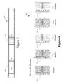
- FIG. 2conceptually illustrates one exemplary embodiment of a component carrier structure 200 .
- the mobile unit 205communicates with a base station 210 over a wireless communication connection 215 .
- the wireless communication connection 215aggregates five carriers 220 (only one indicated by a numeral in FIG. 2 ) to extend the bandwidth of the connection 215 .
- each carrier 220supports a bandwidth of approximately 20 MHz
- the aggregated bandwidth of the wireless communication connection 215is approximately 100 MHz.
- this particular embodimentis intended to be illustrative and that alternative embodiments of the wireless communication connection 215 may include more or fewer aggregated carriers 220 that support larger or smaller individual bandwidths and/or aggregated bandwidth.
- one embodiment of the wireless communication system 100supports asymmetric uplink/downlink (UL/DL) component carriers.
- This embodimentalso supports separate coding of DL assignments and UL grants for each component carrier. Coding of the assignments and grants may be based on DCI format(s) of a single component carrier.
- a carrier indicator field (CIF) including 0-3 bitsmay also be provided to indicate the component carrier (CC) allocation of the respective physical data control channel (PDCCH).
- the carrier indicator fieldallows the allocation of traffic channels in the CC's that may be different from the CC on which PDCCH is transmitted, giving flexibility in carrier selection for PDCCH transmission. This feature may be particularly useful for asymmetric multi-carrier systems.
- the wireless communication system 100may support symmetric uplink/downlink (UL/DL) component carriers.
- mobile units 115would be required to blindly decode the PDCCH for all CCs in the coverage area to obtain information indicating their UL/DL allocation.
- This approachrequires each mobile unit 115 to blindly search all CCs for PDCCHs in each of the CCs and to perform blind decoding for up to 48 different PDCCH hypotheses per CC. If the wireless communication system 100 supports five CCs, each mobile unit 115 would have to perform blind decoding for up to 240 different PDCCH hypotheses. Consequently, the complexity and power consumption of the mobile units 115 would increase as the number of CCs increases. Furthermore, the wireless communication system 100 would not be able to dynamically vary the CC allocation because this would require repeating the blind search and decode process every subframe.
- an alternative implementationallocates an anchor carrier and one or more non-anchor carriers to each mobile unit 115 .
- the term “anchor carrier”will be understood to refer to a component carrier that carries the DL control channels, such as synchronization and system information, and the mobile units 115 use the anchor carrier for the initial access to the system 100 .
- the anchor carriermay be distinguished from non-anchor carriers in one or more respects.
- the anchor carriercontains Release-8 overhead channels such as the physical shared channel (PSCH), the SSCH, the Release-8 broadcast channel (BCH), paging and access channels, and the like.
- the anchor carriermay also carry an indication of scheduling information at the non-anchor carriers.
- the anchor carrierconveys information indicating the active non-anchor carriers in the cell, information indicating the frequency, bandwidth, and/or UL/DL allocation for multi-carrier operation, information indicating a Release 8 compatible PDCCH, and information indicating a PDCCH for resource allocation on the anchor carrier for LTE-A UE.
- both the anchor carrier and the non-anchor carrierscontain physical downlink control channels (PDCCH), pilot channels (PHICH), and physical downlink shared channels (PDSCH) in the DL frequency band.
- the anchor carrier and the non-anchor carrieralso contain physical uplink control channels (PUCCH) and physical uplink shared channels (PUSCH) in the UL frequency.
- the non-anchor carriersdo not require transmission of PSCH, SSCH to minimize the control channel overhead, Release-8 broadcast channel, paging or access channels.
- the anchor carrier and a subset of non-anchor carrierscan be dynamically allocated for LTE-A mobile units 115 . Dynamic allocation of component carriers is useful for multi-carrier operation in the same frequency band.
- the remaining non-anchor carrierscan be used primarily for traffic channels and other control channels for scheduling, resulting in higher peak throughput.
- the non-anchor carriercan be scheduled dynamically, depending on the buffer status and the power/interference condition, providing further efficiency in resource usage.
- the access network 105also includes a scheduler 125 . Although a single scheduler 125 is depicted as part of the access network 105 , persons of ordinary skill in the art having benefit of the present disclosure should appreciate that the scheduler 125 may be implemented at any location or combination of locations.
- the scheduler 125is configured to schedule and/or allocate the anchor and/or non-anchor component carriers to the different mobile units 115 .
- the scheduler 125can dynamically allocate anchor and non-anchor carriers to the mobile units 115 .
- the scheduler 125may be configured to allocate, re-allocate, and/or de-allocate anchor and/or non-anchor component carriers for each subframe in the communication.
- the resource allocation for the anchor carrieris signalled in the PDCCH transmitted in the anchor carrier.
- the anchor carrier PDCCHfor also carries additional bits indicating the non-anchor PDCCHs that have been allocated to the mobile units 115 that receives the anchor carrier PDCCH.
- the additional bitsserve as a pointer to non-anchor carriers that have valid PDCCHs. These additional bits may be referred to as active (non-anchor) component carrier indicator (ACCI) bits.
- ACCIactive (non-anchor) component carrier indicator
- Mobile units 115can decode the ACCI bits to determine the non-anchor CCs and may then attempt PDCCH decoding of the non-anchor component carriers. Similar scheduling may also be used for the uplink, as discussed herein.
- FIG. 3conceptually illustrates one exemplary embodiment of a PDCCH 300 of an anchor component carrier.
- the PDCCH 300includes a set of bits 305 that are used to signal the resource allocation for the anchor carrier.
- the PDCCH 300also includes four bits 310 that are used to indicate the non-anchor PDCCHs that have been allocated to the mobile unit. Although four bits 310 are depicted in FIG. 3 , persons of ordinary skill in the art having benefit of the present disclosure should appreciate that other numbers of bits 310 may be used to signal the non-anchor PDCCHs that have been allocated to the mobile units.
- Table 1shows an example of possible usage of ACCI bits to indicate a full set of component carrier allocation combinations, depending on the number of bits available.
- a 4-bit ACCI fieldcan support 5 CCs with full flexibility for a complete combination set of non-anchor CC allocations. If the number of bits in the ACCI field is less than the number required to indicate all possible CC allocations, a selective subset of combinations of non-anchor CC allocation could be indicated through higher layer signaling.
- One example of a bitmap construction for the ACCI field to support 5 CC allocationsis shown in Table 2.
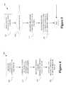
- FIG. 4conceptually illustrates one exemplary embodiment of a method 400 of indicating the component carrier allocation.
- anchor and non-anchor component carriersare allocated (at 405 ) to user equipment.
- a schedulermay determine (at 405 ) the allocation of anchor and/or non-anchor component carriers for a particular subframe.
- An access networkmay then be configured (at 410 ) to transmit information over the allocated anchor carrier to the user equipment.
- configuring (at 410 ) the access networkmay include configuring transmitters in one or more access points or base stations to transmit in the frequency band associated with the allocated anchor carrier.
- the access networkmay also determine bits representative of the resource allocation for the anchor carrier and bits to indicate the allocated non-anchor component carriers. The bits may then be encoded for transmission over the anchor carrier, e.g., using the PDCCH of the anchor carrier.
- the PDCCH informationmay be transmitted over the air interface.
- the anchor carrier informationis transmitted (at 415 ) in a first field of the PDCCH.
- the information identifying the non-anchor carriersmay be transmitted (at 420 ) in a second field of the PDCCH.
- FIG. 4depicts transmission of the first and second field as two separate and sequential steps, persons of ordinary skill in the art having benefit of the present disclosure should appreciate that the first and second fields may be transmitted in any order and/or portions of the fields may be interleaved with each other and/or with other information bits.
- dynamic allocation of the component carriersmay be implemented. In embodiments that implement dynamic allocation, the method 400 may be iterated, e.g., once every subframe or any other selected time, subframe, or frame interval.
- FIG. 5conceptually illustrates one exemplary embodiment of a method 500 that can be used by mobile units or user equipment for decoding PDCCH for multiple component carriers.
- user equipmentattempts (at 505 ) to decode the PDCCH on the anchor carrier.
- user equipmentmay blindly decode (at 505 ) the PDCCH on the anchor carrier.
- the user commanddetermines (at 510 ) whether decoding of the PDCCH has generated a valid PDCCH and ballot information indicating allocated non-anchor carriers (ACCI). If the decoding process failed, then the method 500 ends.
- ACCIallocated non-anchor carriers
- the user equipmentcan proceed to decode (at 515 ) the non-anchor carriers that have valid PDCCHs indicated by the decoded anchor carrier PDCCH.
- the user womanperforms (at 515 ) a blind decode of the non-anchor carrier PDCCHs.
- the user equipmentcan be configured (at 520 ) for communication over the air interface using the anchor carrier and the non-anchor carriers that have been allocated to the user equipment.
- the method 500may be iterated, e.g., once every subframe or any other selected time, subframe, or frame interval, so that dynamic allocation of the anchor carrier and/or non-anchor carriers can be implemented.
- FIG. 6conceptually illustrates one exemplary embodiment of a downlink (DL) channel structure 600 in a multi-component carrier system.
- the systemsupports 5 component carriers 605 ( 1 - 5 ) in the cell coverage area.
- this number of component carriersis intended to be illustrative and not limiting. Alternative embodiments may have different numbers of component carriers.
- the component carrier 605 ( 1 )is allocated as an anchor carrier and the other four component carriers 605 ( 2 - 5 ) are available for allocation as non-anchor carriers.
- the PDCCH in each component carrier 605 ( 1 - 5 )is assumed to carry the resource allocation for the component carrier 605 ( 1 - 5 ).
- the PDCCH in some of the component carriers 605 ( 1 - 5 )may also be used to carry the resource allocations for other component carriers 605 ( 1 - 5 ).
- the resource allocation shown in FIG. 6depicts the resources that are allocated to the user equipment for a particular subframe.
- the user equipmentis allocated DL resources in the anchor carrier 605 ( 1 ) and non-anchor component carriers 605 ( 2 , 4 ).
- the PDCCH for the anchor carrier 605 ( 1 )includes information that identifies the non-anchor component carriers 605 ( 2 , 4 ).
- the PDCCH in an LTE-A DCI format for DL allocationcontains the ACCI indicating that non-anchor component carriers 605 ( 2 , 4 ) have PDCCHs for DL (as indicated by the solid arrow pointers to the corresponding PDCCH).
- the user equipmentcan perform PDCCH blind decoding in non-anchor component carriers 605 ( 2 , 4 ) to retrieve the resource allocation for PDSCH decoding on these carriers.
- the resource allocation for PDSCHcan be indicated by a pointer elements within the PDCCH of the non-anchor component carriers 605 ( 2 , 4 ).
- FIG. 7conceptually illustrates one exemplary embodiment of an UL/DL channel structure 700 in a multi-component carrier system.
- the systemsupports 5 component carriers 705 ( 1 - 5 ) in the cell coverage area.
- this number of component carriersis intended to be illustrative and not limiting. Alternative embodiments may have different numbers of component carriers.
- the component carriers 705 ( 1 - 5 )include both uplink and downlink resources.
- One component carrier 705 ( 1 )is allocated as an anchor carrier and the other four component carriers 705 ( 2 - 5 ) are available for allocation as non-anchor carriers.
- the PDCCH in each component carrier 705 ( 1 - 5 )is assumed to carry the UL resource allocation for the component carrier 705 ( 1 - 5 ).
- the PDCCH in some of the component carriers 705 ( 1 - 5 )may also be used to carry the uplink and or downlink resource allocations for other component carriers 705 ( 1 - 5 ).
- the resource allocation shown in FIG. 7depicts the resources that are allocated to the user equipment for a particular subframe.
- the user equipmentis allocated resources in the anchor carrier 705 ( 1 ) and non-anchor component carriers 705 ( 2 , 4 ).
- the PDCCH for the anchor carrier 705 ( 1 )includes information that identifies the non-anchor component carriers 705 ( 2 , 4 ), e.g., pointers to the PDCCH for the non-anchor component carriers 705 ( 2 , 4 ) that are indicated by the solid arrows.
- the PDCCH in an LTE-A DCI format for UL schedulingcontains the ACCI indicating that non-anchor component carriers 705 ( 2 , 4 ) have PDCCHs for UL.
- the user equipmentcan retrieve the resource allocation for PUSCH decoding on these carriers.
- Information identifying the PUCCH for one or more of the component carriers 705can also be conveyed to the user equipment.
- symmetric UL/DL carriersone can define an association between UL CC and DL CC from the spectrum allocation of the operator or by higher layer signalling such as radio resource control (RRC) signalling.
- RRCradio resource control
- the component carriers 705 that are used for PUCCH transmission corresponding to the DL transmissioncan be signalled to the user equipment.
- the component carrier 705can be semi-statically indicated by higher layer signaling (e.g., RRC signaling).
- the component carrier 705can be dynamically indicated in DL allocation in PDCCH.
- Semi-static PUCCH CC indicationallows the system to reuse Release 8 PUCCH resource allocation techniques and algorithms.
- one or a subset of the UL carriersis preconfigured semi-statically to be associated with the DL carrier for PUCCH transmission.
- the semi-static configurationis done by higher layer signalling, e.g. either by broadcast message or by dedicated RRC signaling.
- the PUCCH component carrier 705is indicated in a dedicated RRC message that indicates the specific PUCCH component carrier 705 that is allocated to the user equipment.
- This scenariomay occur and systems that implement bandwidth extension due to higher bandwidth requirements in the DL direction (relative to the UL direction). Due to smaller number of UL CCs, ACK/NAK corresponding to multiple DL CCs may be mapped UL CCs for PUCCH transmission.
- the ACK/NAK bundling or multiplexing method in TDDcould be used to provide required ACK/NAK resources.
- Embodiments of the techniques described hereincan be used to implement a framework for a low-overhead component carrier allocation.
- a two-step procedure for indicating the PDCCH component carriersis described for the purpose of reducing PDCCH blind decodes.
- Dynamic resource allocation in multiple carriersmay be implemented using PDSCH and PUSCH CC indication.
- a 4-bit active component carrier indicator (ACCI) fieldmay be included in the LTE-A DCI format to indicate the dynamically allocated component carriers for uplink and/or downlink.
- ACCIactive component carrier indicator
- a semi-static configuration methodcan be used to indicate CC for PUCCH transmission.
- the dynamic component carrier allocation and indication techniques described hereinallow low overhead multi-carrier resource allocation with reduced UE PDCCH blind decoding attempts, while potentially reusing Release-8 control channel configurations.
- semi-static configuration of the component carrier indication using RRC signallingis relatively simple and may allow reuse of portions of the Release-e8 PUCCH configuration.
- the software implemented aspects of the disclosed subject matterare typically encoded on some form of program storage medium or implemented over some type of transmission medium.
- the program storage mediummay be magnetic (e.g., a floppy disk or a hard drive) or optical (e.g., a compact disk read only memory, or “CD ROM”), and may be read only or random access.
- the transmission mediummay be twisted wire pairs, coaxial cable, optical fiber, or some other suitable transmission medium known to the art. The disclosed subject matter is not limited by these aspects of any given implementation.
Landscapes
- Engineering & Computer Science (AREA)
- Signal Processing (AREA)
- Computer Networks & Wireless Communication (AREA)
- Mobile Radio Communication Systems (AREA)
Abstract
Description
| TABLE 1 |
| Possible usage of ACCI field depending on number of bits (Example: |
| maximum of 5 CCs, 2 active CCs allocated in a subframe) |
| Number of | |||
| Number | PDCCH blind | ||
| of bits | Usage | decodes | Max number of CCs allocated |
| 1 | Indicates additional allocation | Up to ×4 | 1 (anchor) + 1 (non-anchor) |
| in one | |||
| 2 | Indicates index of one other | Up to ×2 | 1 (anchor) + 1 (non-anchor) |
| CC allocated | |||
| 3 | Indicates indices of two other | Up to ×2 | 1 (anchor) + 2 (non-anchor) |
| CCs allocated | |||
| 4 | Indicates indices of all other | Up to ×2 | 1 (anchor) + 4 (non-anchor) |
| CCs allocated | |||
| TABLE 2 |
| Bitmap of the ACCI field indicating the active non-anchor |
| component carrier (NCC) in a cell with 5 CCs |
| ACCI field | Active non-anchor component carriers |
| 0000 | Reserved |
| 0001 | NCC1 |
| 0010 | NCC2 |
| 0011 | NCC3 |
| 0100 | NCC4 |
| 0101 | NCC1 + NCC2 |
| 0110 | NCC1 + NCC3 |
| 0111 | NCC1 + |
| 1000 | NCC2 + NCC3 |
| 1001 | NCC2 + NCC4 |
| 1010 | NCC3 + NCC4 |
| 1011 | NCC1 + NCC2 + NCC3 |
| 1100 | NCC1 + NCC2 + NCC4 |
| 1101 | NCC1 + NCC3 + NCC4 |
| 1110 | NCC2 + NCC3 + NCC4 |
| 1111 | NCC1 + NCC2 + NCC3 + NCC4 |
Claims (25)
Priority Applications (6)
| Application Number | Priority Date | Filing Date | Title |
|---|---|---|---|
| US12/488,917US8432859B2 (en) | 2009-06-22 | 2009-06-22 | Indicating dynamic allocation of component carriers in multi-component carrier systems |
| EP10723886.7AEP2446683B1 (en) | 2009-06-22 | 2010-06-02 | Indicating dynamic allocation of component carriers in multi-component carrier systems |
| KR1020117030456AKR101369240B1 (en) | 2009-06-22 | 2010-06-02 | Indicating dynamic allocation of component carriers in multi-component carrier systems |
| JP2012517545AJP5770723B2 (en) | 2009-06-22 | 2010-06-02 | Demonstrating dynamic allocation of component carriers in a multi-component carrier system |
| PCT/US2010/037034WO2010151403A1 (en) | 2009-06-22 | 2010-06-02 | Indicating dynamic allocation of component carriers in multi-component carrier systems |
| CN201080027598.3ACN102461301B (en) | 2009-06-22 | 2010-06-02 | Method for indicating dynamic allocation of component carriers in multi-component carrier systems |
Applications Claiming Priority (1)
| Application Number | Priority Date | Filing Date | Title |
|---|---|---|---|
| US12/488,917US8432859B2 (en) | 2009-06-22 | 2009-06-22 | Indicating dynamic allocation of component carriers in multi-component carrier systems |
Publications (2)
| Publication Number | Publication Date |
|---|---|
| US20100322158A1 US20100322158A1 (en) | 2010-12-23 |
| US8432859B2true US8432859B2 (en) | 2013-04-30 |
Family
ID=42710803
Family Applications (1)
| Application Number | Title | Priority Date | Filing Date |
|---|---|---|---|
| US12/488,917Active2030-10-30US8432859B2 (en) | 2009-06-22 | 2009-06-22 | Indicating dynamic allocation of component carriers in multi-component carrier systems |
Country Status (6)
| Country | Link |
|---|---|
| US (1) | US8432859B2 (en) |
| EP (1) | EP2446683B1 (en) |
| JP (1) | JP5770723B2 (en) |
| KR (1) | KR101369240B1 (en) |
| CN (1) | CN102461301B (en) |
| WO (1) | WO2010151403A1 (en) |
Cited By (15)
| Publication number | Priority date | Publication date | Assignee | Title |
|---|---|---|---|---|
| US20110105162A1 (en)* | 2009-11-05 | 2011-05-05 | Pantech Co., Ltd. | Apparatus and method for transmitting and receiving control information in wireless communication system |
| US20110142009A1 (en)* | 2008-03-25 | 2011-06-16 | Bengt Lindoff | Anchor carrier selection in multi-carrier wireless network |
| US20120063358A1 (en)* | 2010-05-03 | 2012-03-15 | Kamran Etemad | Configuring component carriers in carrier aggregation |
| US20120113946A1 (en)* | 2009-07-16 | 2012-05-10 | Dong Youn Seo | Method and apparatus for performing harq in multiple carrier system |
| US20120269151A1 (en)* | 2009-11-27 | 2012-10-25 | Lee Ii Moon | Downlink control information transmitting method and base station, and downlink control information receiving method and user device |
| US20130039284A1 (en)* | 2011-02-11 | 2013-02-14 | Interdigital Patent Holdings, Inc. | Systems and methods for an enhanced control channel |
| US20130058294A1 (en)* | 2010-04-05 | 2013-03-07 | Ntt Docomo, Inc. | Base station apparatus and user terminal |
| US20140226590A1 (en)* | 2009-12-02 | 2014-08-14 | Lg Electronics Inc. | Method and apparatus for mitigating interference in a wireless communication system supporting heterogeneous networks |
| US9930640B2 (en)* | 2008-10-29 | 2018-03-27 | Lg Electronics Inc. | Method for efficiently transmitting physical channel in multi-carrier aggregation state to support broadband |
| US10917917B2 (en)* | 2017-02-01 | 2021-02-09 | Telefonaktiebolaget Ericsson Lm (Publ) | Method for transmitting random access messages on non-anchor carriers |
| US11167582B2 (en) | 2016-02-09 | 2021-11-09 | Toppan Printing Co., Ltd. | Optical element and information recording medium for counterfeit prevention |
| US20210359886A1 (en)* | 2009-09-30 | 2021-11-18 | Optis Wireless Technology, Llc | Reconfiguration of active component carrier set in multi-carrier wireless systems related application |
| US11290153B2 (en)* | 2011-05-06 | 2022-03-29 | Futurewei Technologies, Inc. | System and method for multi-cell access |
| US11305575B2 (en) | 2016-03-30 | 2022-04-19 | Toppan Printing Co., Ltd. | Counterfeit-preventive optical element and information medium |
| US12376078B2 (en) | 2012-01-27 | 2025-07-29 | Interdigital Patent Holdings, Inc. | Systems and/or methods for providing enhanced PDCCH in a multiple carrier based and/or quasi-collated network |
Families Citing this family (63)
| Publication number | Priority date | Publication date | Assignee | Title |
|---|---|---|---|---|
| US9622190B2 (en) | 2006-07-25 | 2017-04-11 | Google Technology Holdings LLC | Spectrum emission level variation in schedulable wireless communication terminal |
| US20080025254A1 (en)* | 2006-07-25 | 2008-01-31 | Motorola Inc | Spectrum emission level variation in schedulable wireless communication terminal |
| US8462746B2 (en)* | 2006-12-27 | 2013-06-11 | Altair Semiconductor Ltd. | Wireless receiver with intermittent shut-off of RF circuits |
| KR20100014091A (en)* | 2008-08-01 | 2010-02-10 | 엘지전자 주식회사 | Method of transmitting data in multiple carrier system |
| US8687545B2 (en)* | 2008-08-11 | 2014-04-01 | Qualcomm Incorporated | Anchor carrier in a multiple carrier wireless communication system |
| KR101089838B1 (en)* | 2008-08-13 | 2011-12-05 | 한국전자통신연구원 | Communication system using carrier aggregation and base stations and terminals belonging to the communication system |
| CN101932098B (en)* | 2009-01-06 | 2013-06-05 | 华为技术有限公司 | Resource allocation method, network equipment and wireless system |
| US20100195586A1 (en)* | 2009-02-05 | 2010-08-05 | Infineon Technologies Ag | Multiband-operation in wireless communication systems |
| US8937901B2 (en)* | 2009-03-17 | 2015-01-20 | Qualcomm Incorporated | Carrier timing for wireless communications systems |
| WO2010148192A1 (en) | 2009-06-18 | 2010-12-23 | Interdigital Patent Holdings, Inc. | Operating in a discontinuous reception mode employing carrier aggregation |
| US9591563B2 (en)* | 2009-07-01 | 2017-03-07 | Telefonaktiebolaget Lm Ericsson (Publ) | Power efficient data transmission |
| WO2011013200A1 (en)* | 2009-07-28 | 2011-02-03 | 富士通株式会社 | Communication system, base station, mobile terminal, and communication method |
| JP4989692B2 (en) | 2009-07-29 | 2012-08-01 | シャープ株式会社 | Mobile communication system, base station apparatus, mobile station apparatus, and communication method |
| JP5322832B2 (en)* | 2009-08-06 | 2013-10-23 | シャープ株式会社 | Mobile station apparatus, base station apparatus, radio communication system, and random access method |
| ES2533320T3 (en)* | 2009-08-14 | 2015-04-09 | Nec Corporation | Detection of a downlink control structure for carrier addition |
| KR101683113B1 (en)* | 2009-08-14 | 2016-12-06 | 엘지전자 주식회사 | Apparatus and metheod for wireless communication between user equipment and base station in a wireless communication system supporting downlink and uplink multipe carriers |
| KR20110019683A (en)* | 2009-08-20 | 2011-02-28 | 주식회사 팬택 | Resource allocation method for each element carrier and communication method of terminal in wireless communication system |
| KR101746525B1 (en)* | 2009-10-01 | 2017-06-14 | 한국전자통신연구원 | Methods of reducing power consumption of User Terminal in mobile communication system using multiple component carrier |
| US8902828B2 (en)* | 2009-10-05 | 2014-12-02 | Qualcomm Incorporated | Carrier indicator field for cross carrier assignments |
| KR20110037426A (en)* | 2009-10-06 | 2011-04-13 | 주식회사 팬택 | Element carrier aggregation information transmission method in wireless communication system and wireless communication system thereof |
| KR101849504B1 (en)* | 2009-10-30 | 2018-04-16 | 블랙베리 리미티드 | Downlink control information set switching when using carrier aggregation |
| WO2011053856A2 (en) | 2009-10-30 | 2011-05-05 | Research In Motion Limited | Reducing blind decodings for communications using carrier aggregation |
| CN101714892B (en)* | 2009-11-02 | 2014-12-31 | 中兴通讯股份有限公司 | Method and system for transmitting downlink control information |
| KR101777416B1 (en)* | 2009-11-26 | 2017-09-27 | 엘지전자 주식회사 | Method of communication for user equipment in carrier aggregation system and user equipment using the same |
| KR101670517B1 (en)* | 2009-11-26 | 2016-10-31 | 엘지전자 주식회사 | Method of uplink cross-carrier scheduling in carrier aggregation system and user equipment using the same |
| EP2512050B1 (en)* | 2009-12-07 | 2018-10-03 | LG Electronics Inc. | Method and apparatus for transmitting and receiving a signal in a wireless communication system that supports plural component carriers |
| JP2011135234A (en)* | 2009-12-22 | 2011-07-07 | Ntt Docomo Inc | Mobile station, wireless base station, and mobile communication method |
| KR20110073334A (en)* | 2009-12-22 | 2011-06-29 | 엘지전자 주식회사 | Device and method for performing uplink HARV in wireless communication system |
| EP2482478B1 (en) | 2010-01-08 | 2021-03-24 | LG Electronics Inc. | Method and apparatus for receiving a downlink signal in a wireless communication system supporting carrier aggregation |
| KR101819501B1 (en)* | 2010-02-04 | 2018-01-17 | 엘지전자 주식회사 | apparatus and method for tranceiving data in wireless communication system supporting multiple component carriers |
| WO2011099695A2 (en)* | 2010-02-09 | 2011-08-18 | 엘지전자 주식회사 | Method for transmitting an uplink signal in a wireless communication system, and apparatus for same |
| EP2360866A1 (en) | 2010-02-12 | 2011-08-24 | Panasonic Corporation | Component carrier activation and deactivation using resource assignments |
| JP5192503B2 (en)* | 2010-02-25 | 2013-05-08 | 株式会社エヌ・ティ・ティ・ドコモ | Information transmission method, base station apparatus and mobile station apparatus |
| KR101789814B1 (en)* | 2010-03-04 | 2017-10-26 | 엘지전자 주식회사 | Method of control information decoding for user equipment in carrier aggregation system and user equipment using the same |
| WO2011121774A1 (en)* | 2010-03-31 | 2011-10-06 | 富士通株式会社 | Wireless communication method, wireless communication system and wireless communication apparatus |
| EP2557710A4 (en)* | 2010-04-07 | 2017-07-26 | LG Electronics Inc. | Pdcch monitoring method and apparatus in a carrier junction system |
| CN102948110B (en) | 2010-04-30 | 2016-01-20 | 黑莓有限公司 | Systems and methods for sharing control channels of carrier aggregation |
| KR101676013B1 (en)* | 2010-05-03 | 2016-11-14 | 삼성전자주식회사 | Methdo and apparatus of control channel reconfiguration in a wireless communication system |
| US8588252B2 (en) | 2010-05-07 | 2013-11-19 | Qualcomm Incorporated | Transmission of control information on uplink channels |
| WO2011145823A2 (en)* | 2010-05-17 | 2011-11-24 | 엘지전자 주식회사 | Method and device for configuring a carrier indication field for a multi-carrier |
| WO2011152669A2 (en)* | 2010-06-04 | 2011-12-08 | Samsung Electronics Co., Ltd. | Method and apparatus for transmitting and receiving paging message using band information in wireless communication system |
| US8923223B2 (en)* | 2010-08-16 | 2014-12-30 | Qualcomm Incorporated | Physical uplink control channel resource allocation for multiple component carriers |
| US8902770B2 (en)* | 2010-09-28 | 2014-12-02 | Nokia Siemens Networks Oy | Carrier indicator field usage and configuration in carrier aggregation |
| US9265004B2 (en)* | 2011-02-02 | 2016-02-16 | Altair Semiconductor Ltd | Intermittent shutoff of RF circuitry in wireless communication terminals |
| CN103404046B (en)* | 2011-03-01 | 2016-09-07 | Lg电子株式会社 | Method and device for searching control information by terminal in multi-node system |
| CN102740488A (en)* | 2011-04-02 | 2012-10-17 | 北京三星通信技术研究有限公司 | Downlink physical resource scheduling indication method in wireless communication system |
| US8934500B2 (en) | 2011-04-13 | 2015-01-13 | Motorola Mobility Llc | Method and apparatus using two radio access technologies for scheduling resources in wireless communication systems |
| US9565655B2 (en) | 2011-04-13 | 2017-02-07 | Google Technology Holdings LLC | Method and apparatus to detect the transmission bandwidth configuration of a channel in connection with reducing interference between channels in wireless communication systems |
| CN102857865B (en)* | 2011-06-29 | 2016-12-07 | 中兴通讯股份有限公司 | Multicarrier system receives method and the subscriber equipment of MBMS |
| KR101986113B1 (en)* | 2011-10-04 | 2019-06-05 | 삼성전자주식회사 | Method and system for signalling and processing control information in a mobile broadband network environment |
| WO2013165160A1 (en)* | 2012-04-30 | 2013-11-07 | 엘지전자 주식회사 | Method for dynamic allocation of radio resources in wireless communication system and device therefor |
| CN104641585B (en)* | 2012-09-14 | 2018-09-18 | 高通股份有限公司 | Uplink ACK/NACK bundling enhancements for LTE TDD-enhanced interference management and traffic adaptation |
| WO2014040274A1 (en)* | 2012-09-14 | 2014-03-20 | Qualcomm Incorporated | Uplink ack/nack bundling enhancement for lte tdd eimta |
| DE102015111565B3 (en)* | 2015-07-16 | 2017-01-12 | Intel IP Corporation | Method and associated mobile device for fast blind decoding |
| KR102603921B1 (en)* | 2015-12-03 | 2023-11-20 | 삼성전자주식회사 | Method of Processing Multiple Component Carriers And Device there-of |
| CN107734667A (en)* | 2016-08-12 | 2018-02-23 | 夏普株式会社 | Perform method, user equipment and the base station of Stochastic accessing |
| WO2018027923A1 (en)* | 2016-08-12 | 2018-02-15 | Mediatek Singapore Pte. Ltd. | Methods and apparatus for cell access via anchor carrier |
| CN112600655A (en) | 2016-12-23 | 2021-04-02 | Oppo广东移动通信有限公司 | Method for transmitting information, network device, terminal device and computer readable medium |
| WO2018174607A1 (en)* | 2017-03-22 | 2018-09-27 | 엘지전자(주) | Method for transmitting and receiving system information in wireless communication system, and apparatus therefor |
| US10511987B2 (en)* | 2017-09-20 | 2019-12-17 | Qualcomm Incorporated | Methods and apparatus related to enhanced machine type communication |
| US11304261B2 (en)* | 2018-05-11 | 2022-04-12 | Apple Inc. | Control information monitoring framework for cellular communication |
| JP7491389B2 (en)* | 2020-10-13 | 2024-05-28 | 日本電信電話株式会社 | Base station and terminal |
| US20250159667A1 (en)* | 2022-04-29 | 2025-05-15 | Qualcomm Incorporated | Techniques for configuring timing advance groups for component carriers |
Citations (15)
| Publication number | Priority date | Publication date | Assignee | Title |
|---|---|---|---|---|
| US20060274712A1 (en)* | 2005-04-28 | 2006-12-07 | Qualcomm Incorporated | Multi-carrier operation in data transmission systems |
| US20090257387A1 (en)* | 2008-03-25 | 2009-10-15 | Qualcomm. Incorporated | Fast carrier allocation in multi-carrier systems |
| US20090300456A1 (en)* | 2008-04-25 | 2009-12-03 | Interdigital Patent Holdings, Inc. | Harq process utilization in multiple carrier wireless communications |
| WO2010048178A1 (en) | 2008-10-20 | 2010-04-29 | Interdigital Patent Holdings, Inc. | Carrier aggregation |
| US20100172290A1 (en)* | 2009-01-08 | 2010-07-08 | Samsung Electronics Co., Ltd. | System and method for an uplink acknowledgement transmission in carrier-aggregated wireless communication systems |
| US20100232373A1 (en)* | 2009-03-16 | 2010-09-16 | Motorola, Inc. | Resource Allocation in Wireless Communication Systems |
| US20100238984A1 (en)* | 2009-03-19 | 2010-09-23 | Motorola, Inc. | Spatial Information Feedback in Wireless Communication Systems |
| US20100260136A1 (en)* | 2009-04-10 | 2010-10-14 | Nokia Corporation | Random access channel response handling with aggregated component carriers |
| US20100273515A1 (en)* | 2009-04-27 | 2010-10-28 | Motorola, Inc. | Uplink Scheduling Support in Multi-Carrier Wireless Communication Systems |
| US20110110441A1 (en)* | 2009-04-30 | 2011-05-12 | Qualcomm Incorporated | Joint layer 3 signalling coding for multicarrier operation |
| US20110111785A1 (en)* | 2008-03-25 | 2011-05-12 | Bengt Lindoff | Timing of component carriers in multi-carrier wireless networks |
| US20110151913A1 (en)* | 2008-08-08 | 2011-06-23 | Josef Forster | Fine-Grain and Backward-Compliant Resource Allocation |
| US20120014306A1 (en)* | 2009-03-31 | 2012-01-19 | Telefonaktiebolaget Lm Ericsson (Publ) | Methods and Arrangements in a Telecommunication System |
| US8184599B2 (en)* | 2008-06-23 | 2012-05-22 | Qualcomm Incorporated | Management of UE operation in a multi-carrier communication system |
| US8194603B2 (en)* | 2009-08-18 | 2012-06-05 | Motorola Mobility, Inc. | Subframe component reduction and notification in a heterogeneous wireless communication system |
Family Cites Families (2)
| Publication number | Priority date | Publication date | Assignee | Title |
|---|---|---|---|---|
| CN100493228C (en)* | 2005-03-10 | 2009-05-27 | 大唐移动通信设备有限公司 | Handover Control Method in Multi-Frequency Point System |
| CA2620545C (en)* | 2005-09-21 | 2013-12-24 | Lg Electronics Inc. | A method of reducing signalling overhead and power consumption in a wireless communication system |
- 2009
- 2009-06-22USUS12/488,917patent/US8432859B2/enactiveActive
- 2010
- 2010-06-02CNCN201080027598.3Apatent/CN102461301B/ennot_activeExpired - Fee Related
- 2010-06-02EPEP10723886.7Apatent/EP2446683B1/ennot_activeNot-in-force
- 2010-06-02KRKR1020117030456Apatent/KR101369240B1/ennot_activeExpired - Fee Related
- 2010-06-02WOPCT/US2010/037034patent/WO2010151403A1/enactiveApplication Filing
- 2010-06-02JPJP2012517545Apatent/JP5770723B2/ennot_activeExpired - Fee Related
Patent Citations (15)
| Publication number | Priority date | Publication date | Assignee | Title |
|---|---|---|---|---|
| US20060274712A1 (en)* | 2005-04-28 | 2006-12-07 | Qualcomm Incorporated | Multi-carrier operation in data transmission systems |
| US20110111785A1 (en)* | 2008-03-25 | 2011-05-12 | Bengt Lindoff | Timing of component carriers in multi-carrier wireless networks |
| US20090257387A1 (en)* | 2008-03-25 | 2009-10-15 | Qualcomm. Incorporated | Fast carrier allocation in multi-carrier systems |
| US20090300456A1 (en)* | 2008-04-25 | 2009-12-03 | Interdigital Patent Holdings, Inc. | Harq process utilization in multiple carrier wireless communications |
| US8184599B2 (en)* | 2008-06-23 | 2012-05-22 | Qualcomm Incorporated | Management of UE operation in a multi-carrier communication system |
| US20110151913A1 (en)* | 2008-08-08 | 2011-06-23 | Josef Forster | Fine-Grain and Backward-Compliant Resource Allocation |
| WO2010048178A1 (en) | 2008-10-20 | 2010-04-29 | Interdigital Patent Holdings, Inc. | Carrier aggregation |
| US20100172290A1 (en)* | 2009-01-08 | 2010-07-08 | Samsung Electronics Co., Ltd. | System and method for an uplink acknowledgement transmission in carrier-aggregated wireless communication systems |
| US20100232373A1 (en)* | 2009-03-16 | 2010-09-16 | Motorola, Inc. | Resource Allocation in Wireless Communication Systems |
| US20100238984A1 (en)* | 2009-03-19 | 2010-09-23 | Motorola, Inc. | Spatial Information Feedback in Wireless Communication Systems |
| US20120014306A1 (en)* | 2009-03-31 | 2012-01-19 | Telefonaktiebolaget Lm Ericsson (Publ) | Methods and Arrangements in a Telecommunication System |
| US20100260136A1 (en)* | 2009-04-10 | 2010-10-14 | Nokia Corporation | Random access channel response handling with aggregated component carriers |
| US20100273515A1 (en)* | 2009-04-27 | 2010-10-28 | Motorola, Inc. | Uplink Scheduling Support in Multi-Carrier Wireless Communication Systems |
| US20110110441A1 (en)* | 2009-04-30 | 2011-05-12 | Qualcomm Incorporated | Joint layer 3 signalling coding for multicarrier operation |
| US8194603B2 (en)* | 2009-08-18 | 2012-06-05 | Motorola Mobility, Inc. | Subframe component reduction and notification in a heterogeneous wireless communication system |
Non-Patent Citations (15)
| Title |
|---|
| 3GPP TR 36.814 V1.1.1, "Further Advancement for E-UTRA-Physical Layer Aspects" Jun. 2009. |
| Alcatel-Lucent et al: "Dynamic PDCCH Monitoring Set Configuration", 3GPP Draft; R1-100916, 3rd Generation Partnership Project (3GPP), Mobile Competence Centre; 650, Route Des Lucioles; F-06921 Sophia-Antipolis Cedex; France, vol. RAN WG1, No. San Francisco, USA; 20100222, Feb. 16, 2010, XP050418516 [retrieved on Feb. 16, 2010] the whole document. |
| Alcatel-Lucent: "Component carrier indication for bandwidth extension in LTE-A" 3GPP Draft; R1-093362, 3rd Generation Partnership Project (3GPP), Mobile Competence Centre; 650, Route Des Lucioles; F-06921 Sophia-Antipolis Cedex; France, No. Shenzhen, China; 20090819, Aug. 19, 2009, XP050351664 [retrieved on Aug. 19, 2009] the whole document. |
| Alcatel-Lucent: "Component carrier indication for bandwidth extension in LTE-A"; 3GPP Draft; R1-092330, 3rd Generation Partnership Project (3GPP), Mobile Competence Centre; 650, Route Des Lucioles; F-06921 Sophia-Antipolis Cedex; France No. Los Angeles, USA; 20090624, Jun. 24, 2009, XP050350855[retrieved on Jun. 24, 2009] the whole document. |
| CMCC: "Consideration on reducing blind decoding attempts for separate PDCCH design", TSG-RAN 56BIS, Mar. 23, 2009, Mar. 25, 2009 pp. 1-6, XP002600621, Seoul, Korea, pp. 3-4. |
| Huawei: "PDCCH design for carrier aggregation", 3GPP Draft; R1-090127 PDCCH Design for carrier aggregation, 3rd Generation Partnership Project (3GPP), Mobile Competence Centre; 650, Route Des Lucioles; F-06921 Sophia-Antipolis Cedex; France, No. Ljubljana; 20090107, Jan. 7, 2009, XP050318065 [retrieved on Jan. 7, 2009] p. 1, paragraph 3, paragraph [02.1]. |
| International Search Report and Written Opinion dated Sep. 27, 2010. |
| Motorola: "Comparison of PDCCH Structures for Carrier Aggregation", 3GPP Draft; R1-091326, 3rd Generation Partnership Project (3GPP), Mobile Competence Centre; 650, Route Des Lucioles; F-06921 Sophia-Antipolis Cedex; France, No. Seoul, Korea; 20090318, Mar. 18, 2009, XP050338924 [retrieved on Mar. 18, 2009] paragraph 3-p. 1. |
| R1-091460, "Multicarrier Control for LTE-Advanced," Qualcomm Europe Mar. 23-27, 2009 Seoul, Korea. |
| R1-091664, "CoMP TP for TR," Qualcomm Europe Mar. 23-27, 2009 Seoul, South Korea. |
| R1-091701, "Asymmetric band aggregation and anchor carrier," ZTE May 4-8, 2009 San Francisco, CA USA. |
| R1-091809, "Component carrier structures," Huawei May 4-8, 2009 San Francisco, CA USA. |
| R1-092061, "Notion of anchor carrier in LTE-A," Qualcomm Europe May 4-8, 2009 San Francisco, CA USA. |
| R1-092180, "Support of non-backward compatible component carriers," Nokia, Nokia Siemens Networks May 4-8, 2009. |
| R1-092219, "Summary of email discussions on bandwidth extension," Nokia, May 4-8, 2009. |
Cited By (30)
| Publication number | Priority date | Publication date | Assignee | Title |
|---|---|---|---|---|
| US20110142009A1 (en)* | 2008-03-25 | 2011-06-16 | Bengt Lindoff | Anchor carrier selection in multi-carrier wireless network |
| US8699467B2 (en)* | 2008-03-25 | 2014-04-15 | Telefonaktiebolaget Lm Ericsson (Publ) | Anchor carrier selection in multi-carrier wireless network |
| US9185706B2 (en) | 2008-03-25 | 2015-11-10 | Telefonaktiebolaget L M Ericsson (Publ) | Anchor carrier selection in multi-carrier wireless network |
| US9930640B2 (en)* | 2008-10-29 | 2018-03-27 | Lg Electronics Inc. | Method for efficiently transmitting physical channel in multi-carrier aggregation state to support broadband |
| US20120113946A1 (en)* | 2009-07-16 | 2012-05-10 | Dong Youn Seo | Method and apparatus for performing harq in multiple carrier system |
| US8630248B2 (en)* | 2009-07-16 | 2014-01-14 | Lg Electronics Inc. | Method and apparatus for performing HARQ in multiple carrier system |
| US20210359886A1 (en)* | 2009-09-30 | 2021-11-18 | Optis Wireless Technology, Llc | Reconfiguration of active component carrier set in multi-carrier wireless systems related application |
| US20110105162A1 (en)* | 2009-11-05 | 2011-05-05 | Pantech Co., Ltd. | Apparatus and method for transmitting and receiving control information in wireless communication system |
| US9178670B2 (en)* | 2009-11-27 | 2015-11-03 | Lg Electronics Inc. | Downlink control information transmitting method and base station, and downlink control information receiving method and user device |
| US20120269151A1 (en)* | 2009-11-27 | 2012-10-25 | Lee Ii Moon | Downlink control information transmitting method and base station, and downlink control information receiving method and user device |
| US9497739B2 (en) | 2009-12-02 | 2016-11-15 | Lg Electronics Inc. | Method and apparatus for mitigating interference in a wireless communication system supporting heterogeneous networks |
| US20140226590A1 (en)* | 2009-12-02 | 2014-08-14 | Lg Electronics Inc. | Method and apparatus for mitigating interference in a wireless communication system supporting heterogeneous networks |
| US9338770B2 (en)* | 2009-12-02 | 2016-05-10 | Lg Electronics Inc. | Method and apparatus for mitigating interference in a wireless communication system supporting heterogeneous networks |
| US8982752B2 (en)* | 2010-04-05 | 2015-03-17 | Ntt Docomo, Inc. | Base station apparatus and user terminal |
| US20130058294A1 (en)* | 2010-04-05 | 2013-03-07 | Ntt Docomo, Inc. | Base station apparatus and user terminal |
| US9338772B2 (en)* | 2010-05-03 | 2016-05-10 | Intel Corporation | Configuring component carriers in carrier aggregation |
| US8743734B2 (en) | 2010-05-03 | 2014-06-03 | Intel Corporation | Configuring component carriers in carrier aggregation |
| US10165560B2 (en)* | 2010-05-03 | 2018-12-25 | Intel Corporation | Configuring component carriers in carrier aggregation |
| US20160255630A1 (en)* | 2010-05-03 | 2016-09-01 | Intel Corporation | Configuring component carriers in carrier aggregation |
| US20120063358A1 (en)* | 2010-05-03 | 2012-03-15 | Kamran Etemad | Configuring component carriers in carrier aggregation |
| US12047309B2 (en) | 2011-02-11 | 2024-07-23 | Interdigital Patent Holdings, Inc. | Systems and methods for an enhanced control channel |
| US20130039284A1 (en)* | 2011-02-11 | 2013-02-14 | Interdigital Patent Holdings, Inc. | Systems and methods for an enhanced control channel |
| US10505680B2 (en)* | 2011-02-11 | 2019-12-10 | Interdigital Patent Holdings, Inc. | Systems and methods for an enhanced control channel |
| US12192125B2 (en) | 2011-02-11 | 2025-01-07 | Interdigital Patent Holdings, Inc. | Systems and methods for an enhanced control channel |
| US11632204B2 (en) | 2011-02-11 | 2023-04-18 | Interdigital Patent Holdings, Inc. | Systems and methods for an enhanced control channel |
| US11290153B2 (en)* | 2011-05-06 | 2022-03-29 | Futurewei Technologies, Inc. | System and method for multi-cell access |
| US12376078B2 (en) | 2012-01-27 | 2025-07-29 | Interdigital Patent Holdings, Inc. | Systems and/or methods for providing enhanced PDCCH in a multiple carrier based and/or quasi-collated network |
| US11167582B2 (en) | 2016-02-09 | 2021-11-09 | Toppan Printing Co., Ltd. | Optical element and information recording medium for counterfeit prevention |
| US11305575B2 (en) | 2016-03-30 | 2022-04-19 | Toppan Printing Co., Ltd. | Counterfeit-preventive optical element and information medium |
| US10917917B2 (en)* | 2017-02-01 | 2021-02-09 | Telefonaktiebolaget Ericsson Lm (Publ) | Method for transmitting random access messages on non-anchor carriers |
Also Published As
| Publication number | Publication date |
|---|---|
| CN102461301A (en) | 2012-05-16 |
| US20100322158A1 (en) | 2010-12-23 |
| EP2446683B1 (en) | 2016-03-30 |
| JP5770723B2 (en) | 2015-08-26 |
| CN102461301B (en) | 2014-10-22 |
| JP2012531163A (en) | 2012-12-06 |
| WO2010151403A1 (en) | 2010-12-29 |
| EP2446683A1 (en) | 2012-05-02 |
| KR101369240B1 (en) | 2014-03-04 |
| KR20120023815A (en) | 2012-03-13 |
Similar Documents
| Publication | Publication Date | Title |
|---|---|---|
| US8432859B2 (en) | Indicating dynamic allocation of component carriers in multi-component carrier systems | |
| US11832089B2 (en) | Systems and methods for multicast resource allocation | |
| US10448388B2 (en) | Method for receiving downlink signal in wireless communication system and terminal using the same | |
| EP3698500B1 (en) | Method and apparatus for transmitting hybrid automatic repeat and request information in a wireless communication system | |
| EP3664549B1 (en) | Method and base statiion for allocating resources in wireless communication system | |
| EP3537810B1 (en) | Method for receiving downlink signal by terminal in wireless communication system, and terminal using same method | |
| US10264564B2 (en) | System and method for resource allocation for massive carrier aggregation | |
| US9065592B2 (en) | Control signaling for transmission over contiguous and non-contiguous frequency bands | |
| US9451610B2 (en) | Wireless terminal and base station | |
| US10588127B2 (en) | Method for communicating in a mobile network | |
| US20160105268A1 (en) | Method for transmitting uplink control information, user equipment, method for receiving uplink control information, and base station | |
| US20130051356A1 (en) | Device and method for transmitting downlink control information in a wireless communication system | |
| EP2439995A2 (en) | Resource mapping method and apparatus in wireless communication system | |
| US20130039272A1 (en) | Method for data transmission and base station and user equipment using the same | |
| EP2498562A1 (en) | Method and base station for sending uplink scheduling grant control signaling | |
| EP2448158A2 (en) | Uplink transmission method and apparatus in wireless communication system | |
| CN102801504A (en) | Control channel mapping and detection methods and devices | |
| EP4429381A1 (en) | Method and device for dynamic switching between downlink data channel transmission or reception schemes in wireless communication system | |
| KR20120124013A (en) | Method And Apparatus For Resource Allocation And Obtainment |
Legal Events
| Date | Code | Title | Description |
|---|---|---|---|
| AS | Assignment | Owner name:ALCATEL-LUCENT U.S.A., INC., NEW JERSEY Free format text:ASSIGNMENT OF ASSIGNORS INTEREST;ASSIGNORS:CHANG, FANG-CHEN;LEE, JUNG AH;REEL/FRAME:022857/0056 Effective date:20090619 | |
| AS | Assignment | Owner name:ALCATEL LUCENT, FRANCE Free format text:ASSIGNMENT OF ASSIGNORS INTEREST;ASSIGNOR:ALCATEL-LUCENT USA INC.;REEL/FRAME:026494/0767 Effective date:20110621 | |
| FEPP | Fee payment procedure | Free format text:PAYOR NUMBER ASSIGNED (ORIGINAL EVENT CODE: ASPN); ENTITY STATUS OF PATENT OWNER: LARGE ENTITY | |
| AS | Assignment | Owner name:CREDIT SUISSE AG, NEW YORK Free format text:SECURITY AGREEMENT;ASSIGNOR:LUCENT, ALCATEL;REEL/FRAME:029821/0001 Effective date:20130130 Owner name:CREDIT SUISSE AG, NEW YORK Free format text:SECURITY AGREEMENT;ASSIGNOR:ALCATEL LUCENT;REEL/FRAME:029821/0001 Effective date:20130130 | |
| STCF | Information on status: patent grant | Free format text:PATENTED CASE | |
| AS | Assignment | Owner name:ALCATEL LUCENT, FRANCE Free format text:RELEASE BY SECURED PARTY;ASSIGNOR:CREDIT SUISSE AG;REEL/FRAME:033868/0555 Effective date:20140819 | |
| FPAY | Fee payment | Year of fee payment:4 | |
| AS | Assignment | Owner name:OMEGA CREDIT OPPORTUNITIES MASTER FUND, LP, NEW YORK Free format text:SECURITY INTEREST;ASSIGNOR:WSOU INVESTMENTS, LLC;REEL/FRAME:043966/0574 Effective date:20170822 Owner name:OMEGA CREDIT OPPORTUNITIES MASTER FUND, LP, NEW YO Free format text:SECURITY INTEREST;ASSIGNOR:WSOU INVESTMENTS, LLC;REEL/FRAME:043966/0574 Effective date:20170822 | |
| AS | Assignment | Owner name:WSOU INVESTMENTS, LLC, CALIFORNIA Free format text:ASSIGNMENT OF ASSIGNORS INTEREST;ASSIGNOR:ALCATEL LUCENT;REEL/FRAME:044000/0053 Effective date:20170722 | |
| AS | Assignment | Owner name:BP FUNDING TRUST, SERIES SPL-VI, NEW YORK Free format text:SECURITY INTEREST;ASSIGNOR:WSOU INVESTMENTS, LLC;REEL/FRAME:049235/0068 Effective date:20190516 | |
| AS | Assignment | Owner name:WSOU INVESTMENTS, LLC, CALIFORNIA Free format text:RELEASE BY SECURED PARTY;ASSIGNOR:OCO OPPORTUNITIES MASTER FUND, L.P. (F/K/A OMEGA CREDIT OPPORTUNITIES MASTER FUND LP;REEL/FRAME:049246/0405 Effective date:20190516 | |
| MAFP | Maintenance fee payment | Free format text:PAYMENT OF MAINTENANCE FEE, 8TH YEAR, LARGE ENTITY (ORIGINAL EVENT CODE: M1552); ENTITY STATUS OF PATENT OWNER: LARGE ENTITY Year of fee payment:8 | |
| AS | Assignment | Owner name:OT WSOU TERRIER HOLDINGS, LLC, CALIFORNIA Free format text:SECURITY INTEREST;ASSIGNOR:WSOU INVESTMENTS, LLC;REEL/FRAME:056990/0081 Effective date:20210528 | |
| AS | Assignment | Owner name:WSOU INVESTMENTS, LLC, CALIFORNIA Free format text:RELEASE BY SECURED PARTY;ASSIGNOR:TERRIER SSC, LLC;REEL/FRAME:056526/0093 Effective date:20210528 | |
| FEPP | Fee payment procedure | Free format text:MAINTENANCE FEE REMINDER MAILED (ORIGINAL EVENT CODE: REM.); ENTITY STATUS OF PATENT OWNER: LARGE ENTITY | |
| FEPP | Fee payment procedure | Free format text:11.5 YR SURCHARGE- LATE PMT W/IN 6 MO, LARGE ENTITY (ORIGINAL EVENT CODE: M1556); ENTITY STATUS OF PATENT OWNER: LARGE ENTITY | |
| MAFP | Maintenance fee payment | Free format text:PAYMENT OF MAINTENANCE FEE, 12TH YEAR, LARGE ENTITY (ORIGINAL EVENT CODE: M1553); ENTITY STATUS OF PATENT OWNER: LARGE ENTITY Year of fee payment:12 |