US8430930B2 - Truss implant - Google Patents
Truss implantDownload PDFInfo
- Publication number
- US8430930B2 US8430930B2US12/640,825US64082509AUS8430930B2US 8430930 B2US8430930 B2US 8430930B2US 64082509 AUS64082509 AUS 64082509AUS 8430930 B2US8430930 B2US 8430930B2
- Authority
- US
- United States
- Prior art keywords
- implant
- truss
- struts
- truss structure
- contact
- Prior art date
- Legal status (The legal status is an assumption and is not a legal conclusion. Google has not performed a legal analysis and makes no representation as to the accuracy of the status listed.)
- Active, expires
Links
- MOYQXWGTQSPBFX-UHFFFAOYSA-NC(C1C2C3C4C5C6C78C3C47)C11C3C4C8C6(C6)C5C6=C5C4C4C1C2C3C54Chemical compoundC(C1C2C3C4C5C6C78C3C47)C11C3C4C8C6(C6)C5C6=C5C4C4C1C2C3C54MOYQXWGTQSPBFX-UHFFFAOYSA-N0.000description1
Images


Classifications
- A—HUMAN NECESSITIES
- A61—MEDICAL OR VETERINARY SCIENCE; HYGIENE
- A61F—FILTERS IMPLANTABLE INTO BLOOD VESSELS; PROSTHESES; DEVICES PROVIDING PATENCY TO, OR PREVENTING COLLAPSING OF, TUBULAR STRUCTURES OF THE BODY, e.g. STENTS; ORTHOPAEDIC, NURSING OR CONTRACEPTIVE DEVICES; FOMENTATION; TREATMENT OR PROTECTION OF EYES OR EARS; BANDAGES, DRESSINGS OR ABSORBENT PADS; FIRST-AID KITS
- A61F2/00—Filters implantable into blood vessels; Prostheses, i.e. artificial substitutes or replacements for parts of the body; Appliances for connecting them with the body; Devices providing patency to, or preventing collapsing of, tubular structures of the body, e.g. stents
- A61F2/02—Prostheses implantable into the body
- A61F2/30—Joints
- A61F2/44—Joints for the spine, e.g. vertebrae, spinal discs
- A61F2/4455—Joints for the spine, e.g. vertebrae, spinal discs for the fusion of spinal bodies, e.g. intervertebral fusion of adjacent spinal bodies, e.g. fusion cages
- A—HUMAN NECESSITIES
- A61—MEDICAL OR VETERINARY SCIENCE; HYGIENE
- A61B—DIAGNOSIS; SURGERY; IDENTIFICATION
- A61B17/00—Surgical instruments, devices or methods
- A61B17/16—Instruments for performing osteoclasis; Drills or chisels for bones; Trepans
- A61B17/1604—Chisels; Rongeurs; Punches; Stamps
- A—HUMAN NECESSITIES
- A61—MEDICAL OR VETERINARY SCIENCE; HYGIENE
- A61B—DIAGNOSIS; SURGERY; IDENTIFICATION
- A61B17/00—Surgical instruments, devices or methods
- A61B17/56—Surgical instruments or methods for treatment of bones or joints; Devices specially adapted therefor
- A—HUMAN NECESSITIES
- A61—MEDICAL OR VETERINARY SCIENCE; HYGIENE
- A61B—DIAGNOSIS; SURGERY; IDENTIFICATION
- A61B17/00—Surgical instruments, devices or methods
- A61B17/56—Surgical instruments or methods for treatment of bones or joints; Devices specially adapted therefor
- A61B17/58—Surgical instruments or methods for treatment of bones or joints; Devices specially adapted therefor for osteosynthesis, e.g. bone plates, screws or setting implements
- A61B17/68—Internal fixation devices, including fasteners and spinal fixators, even if a part thereof projects from the skin
- A—HUMAN NECESSITIES
- A61—MEDICAL OR VETERINARY SCIENCE; HYGIENE
- A61F—FILTERS IMPLANTABLE INTO BLOOD VESSELS; PROSTHESES; DEVICES PROVIDING PATENCY TO, OR PREVENTING COLLAPSING OF, TUBULAR STRUCTURES OF THE BODY, e.g. STENTS; ORTHOPAEDIC, NURSING OR CONTRACEPTIVE DEVICES; FOMENTATION; TREATMENT OR PROTECTION OF EYES OR EARS; BANDAGES, DRESSINGS OR ABSORBENT PADS; FIRST-AID KITS
- A61F2/00—Filters implantable into blood vessels; Prostheses, i.e. artificial substitutes or replacements for parts of the body; Appliances for connecting them with the body; Devices providing patency to, or preventing collapsing of, tubular structures of the body, e.g. stents
- A61F2/02—Prostheses implantable into the body
- A61F2/28—Bones
- A61F2/2803—Bones for mandibular reconstruction
- A—HUMAN NECESSITIES
- A61—MEDICAL OR VETERINARY SCIENCE; HYGIENE
- A61F—FILTERS IMPLANTABLE INTO BLOOD VESSELS; PROSTHESES; DEVICES PROVIDING PATENCY TO, OR PREVENTING COLLAPSING OF, TUBULAR STRUCTURES OF THE BODY, e.g. STENTS; ORTHOPAEDIC, NURSING OR CONTRACEPTIVE DEVICES; FOMENTATION; TREATMENT OR PROTECTION OF EYES OR EARS; BANDAGES, DRESSINGS OR ABSORBENT PADS; FIRST-AID KITS
- A61F2/00—Filters implantable into blood vessels; Prostheses, i.e. artificial substitutes or replacements for parts of the body; Appliances for connecting them with the body; Devices providing patency to, or preventing collapsing of, tubular structures of the body, e.g. stents
- A61F2/02—Prostheses implantable into the body
- A61F2/28—Bones
- A61F2/2846—Support means for bone substitute or for bone graft implants, e.g. membranes or plates for covering bone defects
- A—HUMAN NECESSITIES
- A61—MEDICAL OR VETERINARY SCIENCE; HYGIENE
- A61F—FILTERS IMPLANTABLE INTO BLOOD VESSELS; PROSTHESES; DEVICES PROVIDING PATENCY TO, OR PREVENTING COLLAPSING OF, TUBULAR STRUCTURES OF THE BODY, e.g. STENTS; ORTHOPAEDIC, NURSING OR CONTRACEPTIVE DEVICES; FOMENTATION; TREATMENT OR PROTECTION OF EYES OR EARS; BANDAGES, DRESSINGS OR ABSORBENT PADS; FIRST-AID KITS
- A61F2/00—Filters implantable into blood vessels; Prostheses, i.e. artificial substitutes or replacements for parts of the body; Appliances for connecting them with the body; Devices providing patency to, or preventing collapsing of, tubular structures of the body, e.g. stents
- A61F2/02—Prostheses implantable into the body
- A61F2/30—Joints
- A61F2/30767—Special external or bone-contacting surface, e.g. coating for improving bone ingrowth
- A61F2/30771—Special external or bone-contacting surface, e.g. coating for improving bone ingrowth applied in original prostheses, e.g. holes or grooves
- A—HUMAN NECESSITIES
- A61—MEDICAL OR VETERINARY SCIENCE; HYGIENE
- A61F—FILTERS IMPLANTABLE INTO BLOOD VESSELS; PROSTHESES; DEVICES PROVIDING PATENCY TO, OR PREVENTING COLLAPSING OF, TUBULAR STRUCTURES OF THE BODY, e.g. STENTS; ORTHOPAEDIC, NURSING OR CONTRACEPTIVE DEVICES; FOMENTATION; TREATMENT OR PROTECTION OF EYES OR EARS; BANDAGES, DRESSINGS OR ABSORBENT PADS; FIRST-AID KITS
- A61F2/00—Filters implantable into blood vessels; Prostheses, i.e. artificial substitutes or replacements for parts of the body; Appliances for connecting them with the body; Devices providing patency to, or preventing collapsing of, tubular structures of the body, e.g. stents
- A61F2/02—Prostheses implantable into the body
- A61F2/30—Joints
- A61F2/30767—Special external or bone-contacting surface, e.g. coating for improving bone ingrowth
- A61F2/30907—Nets or sleeves applied to surface of prostheses or in cement
- A—HUMAN NECESSITIES
- A61—MEDICAL OR VETERINARY SCIENCE; HYGIENE
- A61F—FILTERS IMPLANTABLE INTO BLOOD VESSELS; PROSTHESES; DEVICES PROVIDING PATENCY TO, OR PREVENTING COLLAPSING OF, TUBULAR STRUCTURES OF THE BODY, e.g. STENTS; ORTHOPAEDIC, NURSING OR CONTRACEPTIVE DEVICES; FOMENTATION; TREATMENT OR PROTECTION OF EYES OR EARS; BANDAGES, DRESSINGS OR ABSORBENT PADS; FIRST-AID KITS
- A61F2/00—Filters implantable into blood vessels; Prostheses, i.e. artificial substitutes or replacements for parts of the body; Appliances for connecting them with the body; Devices providing patency to, or preventing collapsing of, tubular structures of the body, e.g. stents
- A61F2/02—Prostheses implantable into the body
- A61F2/30—Joints
- A61F2/32—Joints for the hip
- A—HUMAN NECESSITIES
- A61—MEDICAL OR VETERINARY SCIENCE; HYGIENE
- A61F—FILTERS IMPLANTABLE INTO BLOOD VESSELS; PROSTHESES; DEVICES PROVIDING PATENCY TO, OR PREVENTING COLLAPSING OF, TUBULAR STRUCTURES OF THE BODY, e.g. STENTS; ORTHOPAEDIC, NURSING OR CONTRACEPTIVE DEVICES; FOMENTATION; TREATMENT OR PROTECTION OF EYES OR EARS; BANDAGES, DRESSINGS OR ABSORBENT PADS; FIRST-AID KITS
- A61F2/00—Filters implantable into blood vessels; Prostheses, i.e. artificial substitutes or replacements for parts of the body; Appliances for connecting them with the body; Devices providing patency to, or preventing collapsing of, tubular structures of the body, e.g. stents
- A61F2/02—Prostheses implantable into the body
- A61F2/30—Joints
- A61F2/38—Joints for elbows or knees
- A—HUMAN NECESSITIES
- A61—MEDICAL OR VETERINARY SCIENCE; HYGIENE
- A61F—FILTERS IMPLANTABLE INTO BLOOD VESSELS; PROSTHESES; DEVICES PROVIDING PATENCY TO, OR PREVENTING COLLAPSING OF, TUBULAR STRUCTURES OF THE BODY, e.g. STENTS; ORTHOPAEDIC, NURSING OR CONTRACEPTIVE DEVICES; FOMENTATION; TREATMENT OR PROTECTION OF EYES OR EARS; BANDAGES, DRESSINGS OR ABSORBENT PADS; FIRST-AID KITS
- A61F2/00—Filters implantable into blood vessels; Prostheses, i.e. artificial substitutes or replacements for parts of the body; Appliances for connecting them with the body; Devices providing patency to, or preventing collapsing of, tubular structures of the body, e.g. stents
- A61F2/02—Prostheses implantable into the body
- A61F2/30—Joints
- A61F2/40—Joints for shoulders
- A—HUMAN NECESSITIES
- A61—MEDICAL OR VETERINARY SCIENCE; HYGIENE
- A61F—FILTERS IMPLANTABLE INTO BLOOD VESSELS; PROSTHESES; DEVICES PROVIDING PATENCY TO, OR PREVENTING COLLAPSING OF, TUBULAR STRUCTURES OF THE BODY, e.g. STENTS; ORTHOPAEDIC, NURSING OR CONTRACEPTIVE DEVICES; FOMENTATION; TREATMENT OR PROTECTION OF EYES OR EARS; BANDAGES, DRESSINGS OR ABSORBENT PADS; FIRST-AID KITS
- A61F2/00—Filters implantable into blood vessels; Prostheses, i.e. artificial substitutes or replacements for parts of the body; Appliances for connecting them with the body; Devices providing patency to, or preventing collapsing of, tubular structures of the body, e.g. stents
- A61F2/02—Prostheses implantable into the body
- A61F2/30—Joints
- A61F2/42—Joints for wrists or ankles; for hands, e.g. fingers; for feet, e.g. toes
- A61F2/4202—Joints for wrists or ankles; for hands, e.g. fingers; for feet, e.g. toes for ankles
- A—HUMAN NECESSITIES
- A61—MEDICAL OR VETERINARY SCIENCE; HYGIENE
- A61F—FILTERS IMPLANTABLE INTO BLOOD VESSELS; PROSTHESES; DEVICES PROVIDING PATENCY TO, OR PREVENTING COLLAPSING OF, TUBULAR STRUCTURES OF THE BODY, e.g. STENTS; ORTHOPAEDIC, NURSING OR CONTRACEPTIVE DEVICES; FOMENTATION; TREATMENT OR PROTECTION OF EYES OR EARS; BANDAGES, DRESSINGS OR ABSORBENT PADS; FIRST-AID KITS
- A61F2/00—Filters implantable into blood vessels; Prostheses, i.e. artificial substitutes or replacements for parts of the body; Appliances for connecting them with the body; Devices providing patency to, or preventing collapsing of, tubular structures of the body, e.g. stents
- A61F2/02—Prostheses implantable into the body
- A61F2/30—Joints
- A61F2/42—Joints for wrists or ankles; for hands, e.g. fingers; for feet, e.g. toes
- A61F2/4225—Joints for wrists or ankles; for hands, e.g. fingers; for feet, e.g. toes for feet, e.g. toes
- A—HUMAN NECESSITIES
- A61—MEDICAL OR VETERINARY SCIENCE; HYGIENE
- A61F—FILTERS IMPLANTABLE INTO BLOOD VESSELS; PROSTHESES; DEVICES PROVIDING PATENCY TO, OR PREVENTING COLLAPSING OF, TUBULAR STRUCTURES OF THE BODY, e.g. STENTS; ORTHOPAEDIC, NURSING OR CONTRACEPTIVE DEVICES; FOMENTATION; TREATMENT OR PROTECTION OF EYES OR EARS; BANDAGES, DRESSINGS OR ABSORBENT PADS; FIRST-AID KITS
- A61F2/00—Filters implantable into blood vessels; Prostheses, i.e. artificial substitutes or replacements for parts of the body; Appliances for connecting them with the body; Devices providing patency to, or preventing collapsing of, tubular structures of the body, e.g. stents
- A61F2/02—Prostheses implantable into the body
- A61F2/30—Joints
- A61F2/44—Joints for the spine, e.g. vertebrae, spinal discs
- A61F2/4455—Joints for the spine, e.g. vertebrae, spinal discs for the fusion of spinal bodies, e.g. intervertebral fusion of adjacent spinal bodies, e.g. fusion cages
- A61F2/447—Joints for the spine, e.g. vertebrae, spinal discs for the fusion of spinal bodies, e.g. intervertebral fusion of adjacent spinal bodies, e.g. fusion cages substantially parallelepipedal, e.g. having a rectangular or trapezoidal cross-section
- A—HUMAN NECESSITIES
- A61—MEDICAL OR VETERINARY SCIENCE; HYGIENE
- A61F—FILTERS IMPLANTABLE INTO BLOOD VESSELS; PROSTHESES; DEVICES PROVIDING PATENCY TO, OR PREVENTING COLLAPSING OF, TUBULAR STRUCTURES OF THE BODY, e.g. STENTS; ORTHOPAEDIC, NURSING OR CONTRACEPTIVE DEVICES; FOMENTATION; TREATMENT OR PROTECTION OF EYES OR EARS; BANDAGES, DRESSINGS OR ABSORBENT PADS; FIRST-AID KITS
- A61F2/00—Filters implantable into blood vessels; Prostheses, i.e. artificial substitutes or replacements for parts of the body; Appliances for connecting them with the body; Devices providing patency to, or preventing collapsing of, tubular structures of the body, e.g. stents
- A61F2/02—Prostheses implantable into the body
- A61F2/30—Joints
- A61F2/46—Special tools for implanting artificial joints
- A61F2/4603—Special tools for implanting artificial joints for insertion or extraction of endoprosthetic joints or of accessories thereof
- A61F2/4611—Special tools for implanting artificial joints for insertion or extraction of endoprosthetic joints or of accessories thereof of spinal prostheses
- A—HUMAN NECESSITIES
- A61—MEDICAL OR VETERINARY SCIENCE; HYGIENE
- A61B—DIAGNOSIS; SURGERY; IDENTIFICATION
- A61B17/00—Surgical instruments, devices or methods
- A61B17/02—Surgical instruments, devices or methods for holding wounds open, e.g. retractors; Tractors
- A61B17/025—Joint distractors
- A—HUMAN NECESSITIES
- A61—MEDICAL OR VETERINARY SCIENCE; HYGIENE
- A61F—FILTERS IMPLANTABLE INTO BLOOD VESSELS; PROSTHESES; DEVICES PROVIDING PATENCY TO, OR PREVENTING COLLAPSING OF, TUBULAR STRUCTURES OF THE BODY, e.g. STENTS; ORTHOPAEDIC, NURSING OR CONTRACEPTIVE DEVICES; FOMENTATION; TREATMENT OR PROTECTION OF EYES OR EARS; BANDAGES, DRESSINGS OR ABSORBENT PADS; FIRST-AID KITS
- A61F2/00—Filters implantable into blood vessels; Prostheses, i.e. artificial substitutes or replacements for parts of the body; Appliances for connecting them with the body; Devices providing patency to, or preventing collapsing of, tubular structures of the body, e.g. stents
- A61F2/02—Prostheses implantable into the body
- A61F2/30—Joints
- A61F2/3094—Designing or manufacturing processes
- A—HUMAN NECESSITIES
- A61—MEDICAL OR VETERINARY SCIENCE; HYGIENE
- A61F—FILTERS IMPLANTABLE INTO BLOOD VESSELS; PROSTHESES; DEVICES PROVIDING PATENCY TO, OR PREVENTING COLLAPSING OF, TUBULAR STRUCTURES OF THE BODY, e.g. STENTS; ORTHOPAEDIC, NURSING OR CONTRACEPTIVE DEVICES; FOMENTATION; TREATMENT OR PROTECTION OF EYES OR EARS; BANDAGES, DRESSINGS OR ABSORBENT PADS; FIRST-AID KITS
- A61F2/00—Filters implantable into blood vessels; Prostheses, i.e. artificial substitutes or replacements for parts of the body; Appliances for connecting them with the body; Devices providing patency to, or preventing collapsing of, tubular structures of the body, e.g. stents
- A61F2/02—Prostheses implantable into the body
- A61F2/30—Joints
- A61F2/32—Joints for the hip
- A61F2/36—Femoral heads ; Femoral endoprostheses
- A—HUMAN NECESSITIES
- A61—MEDICAL OR VETERINARY SCIENCE; HYGIENE
- A61F—FILTERS IMPLANTABLE INTO BLOOD VESSELS; PROSTHESES; DEVICES PROVIDING PATENCY TO, OR PREVENTING COLLAPSING OF, TUBULAR STRUCTURES OF THE BODY, e.g. STENTS; ORTHOPAEDIC, NURSING OR CONTRACEPTIVE DEVICES; FOMENTATION; TREATMENT OR PROTECTION OF EYES OR EARS; BANDAGES, DRESSINGS OR ABSORBENT PADS; FIRST-AID KITS
- A61F2/00—Filters implantable into blood vessels; Prostheses, i.e. artificial substitutes or replacements for parts of the body; Appliances for connecting them with the body; Devices providing patency to, or preventing collapsing of, tubular structures of the body, e.g. stents
- A61F2/02—Prostheses implantable into the body
- A61F2/28—Bones
- A61F2002/2817—Bone stimulation by chemical reactions or by osteogenic or biological products for enhancing ossification, e.g. by bone morphogenetic or morphogenic proteins [BMP] or by transforming growth factors [TGF]
- A—HUMAN NECESSITIES
- A61—MEDICAL OR VETERINARY SCIENCE; HYGIENE
- A61F—FILTERS IMPLANTABLE INTO BLOOD VESSELS; PROSTHESES; DEVICES PROVIDING PATENCY TO, OR PREVENTING COLLAPSING OF, TUBULAR STRUCTURES OF THE BODY, e.g. STENTS; ORTHOPAEDIC, NURSING OR CONTRACEPTIVE DEVICES; FOMENTATION; TREATMENT OR PROTECTION OF EYES OR EARS; BANDAGES, DRESSINGS OR ABSORBENT PADS; FIRST-AID KITS
- A61F2/00—Filters implantable into blood vessels; Prostheses, i.e. artificial substitutes or replacements for parts of the body; Appliances for connecting them with the body; Devices providing patency to, or preventing collapsing of, tubular structures of the body, e.g. stents
- A61F2/02—Prostheses implantable into the body
- A61F2/28—Bones
- A61F2002/2835—Bone graft implants for filling a bony defect or an endoprosthesis cavity, e.g. by synthetic material or biological material
- A—HUMAN NECESSITIES
- A61—MEDICAL OR VETERINARY SCIENCE; HYGIENE
- A61F—FILTERS IMPLANTABLE INTO BLOOD VESSELS; PROSTHESES; DEVICES PROVIDING PATENCY TO, OR PREVENTING COLLAPSING OF, TUBULAR STRUCTURES OF THE BODY, e.g. STENTS; ORTHOPAEDIC, NURSING OR CONTRACEPTIVE DEVICES; FOMENTATION; TREATMENT OR PROTECTION OF EYES OR EARS; BANDAGES, DRESSINGS OR ABSORBENT PADS; FIRST-AID KITS
- A61F2/00—Filters implantable into blood vessels; Prostheses, i.e. artificial substitutes or replacements for parts of the body; Appliances for connecting them with the body; Devices providing patency to, or preventing collapsing of, tubular structures of the body, e.g. stents
- A61F2/02—Prostheses implantable into the body
- A61F2/30—Joints
- A61F2002/30001—Additional features of subject-matter classified in A61F2/28, A61F2/30 and subgroups thereof
- A61F2002/30108—Shapes
- A61F2002/3011—Cross-sections or two-dimensional shapes
- A61F2002/30138—Convex polygonal shapes
- A61F2002/30153—Convex polygonal shapes rectangular
- A—HUMAN NECESSITIES
- A61—MEDICAL OR VETERINARY SCIENCE; HYGIENE
- A61F—FILTERS IMPLANTABLE INTO BLOOD VESSELS; PROSTHESES; DEVICES PROVIDING PATENCY TO, OR PREVENTING COLLAPSING OF, TUBULAR STRUCTURES OF THE BODY, e.g. STENTS; ORTHOPAEDIC, NURSING OR CONTRACEPTIVE DEVICES; FOMENTATION; TREATMENT OR PROTECTION OF EYES OR EARS; BANDAGES, DRESSINGS OR ABSORBENT PADS; FIRST-AID KITS
- A61F2/00—Filters implantable into blood vessels; Prostheses, i.e. artificial substitutes or replacements for parts of the body; Appliances for connecting them with the body; Devices providing patency to, or preventing collapsing of, tubular structures of the body, e.g. stents
- A61F2/02—Prostheses implantable into the body
- A61F2/30—Joints
- A61F2002/30001—Additional features of subject-matter classified in A61F2/28, A61F2/30 and subgroups thereof
- A61F2002/30108—Shapes
- A61F2002/3011—Cross-sections or two-dimensional shapes
- A61F2002/30138—Convex polygonal shapes
- A61F2002/30156—Convex polygonal shapes triangular
- A—HUMAN NECESSITIES
- A61—MEDICAL OR VETERINARY SCIENCE; HYGIENE
- A61F—FILTERS IMPLANTABLE INTO BLOOD VESSELS; PROSTHESES; DEVICES PROVIDING PATENCY TO, OR PREVENTING COLLAPSING OF, TUBULAR STRUCTURES OF THE BODY, e.g. STENTS; ORTHOPAEDIC, NURSING OR CONTRACEPTIVE DEVICES; FOMENTATION; TREATMENT OR PROTECTION OF EYES OR EARS; BANDAGES, DRESSINGS OR ABSORBENT PADS; FIRST-AID KITS
- A61F2/00—Filters implantable into blood vessels; Prostheses, i.e. artificial substitutes or replacements for parts of the body; Appliances for connecting them with the body; Devices providing patency to, or preventing collapsing of, tubular structures of the body, e.g. stents
- A61F2/02—Prostheses implantable into the body
- A61F2/30—Joints
- A61F2002/30001—Additional features of subject-matter classified in A61F2/28, A61F2/30 and subgroups thereof
- A61F2002/30108—Shapes
- A61F2002/3011—Cross-sections or two-dimensional shapes
- A61F2002/30138—Convex polygonal shapes
- A61F2002/30158—Convex polygonal shapes trapezoidal
- A—HUMAN NECESSITIES
- A61—MEDICAL OR VETERINARY SCIENCE; HYGIENE
- A61F—FILTERS IMPLANTABLE INTO BLOOD VESSELS; PROSTHESES; DEVICES PROVIDING PATENCY TO, OR PREVENTING COLLAPSING OF, TUBULAR STRUCTURES OF THE BODY, e.g. STENTS; ORTHOPAEDIC, NURSING OR CONTRACEPTIVE DEVICES; FOMENTATION; TREATMENT OR PROTECTION OF EYES OR EARS; BANDAGES, DRESSINGS OR ABSORBENT PADS; FIRST-AID KITS
- A61F2/00—Filters implantable into blood vessels; Prostheses, i.e. artificial substitutes or replacements for parts of the body; Appliances for connecting them with the body; Devices providing patency to, or preventing collapsing of, tubular structures of the body, e.g. stents
- A61F2/02—Prostheses implantable into the body
- A61F2/30—Joints
- A61F2002/30001—Additional features of subject-matter classified in A61F2/28, A61F2/30 and subgroups thereof
- A61F2002/30108—Shapes
- A61F2002/3011—Cross-sections or two-dimensional shapes
- A61F2002/30159—Concave polygonal shapes
- A61F2002/30179—X-shaped
- A—HUMAN NECESSITIES
- A61—MEDICAL OR VETERINARY SCIENCE; HYGIENE
- A61F—FILTERS IMPLANTABLE INTO BLOOD VESSELS; PROSTHESES; DEVICES PROVIDING PATENCY TO, OR PREVENTING COLLAPSING OF, TUBULAR STRUCTURES OF THE BODY, e.g. STENTS; ORTHOPAEDIC, NURSING OR CONTRACEPTIVE DEVICES; FOMENTATION; TREATMENT OR PROTECTION OF EYES OR EARS; BANDAGES, DRESSINGS OR ABSORBENT PADS; FIRST-AID KITS
- A61F2/00—Filters implantable into blood vessels; Prostheses, i.e. artificial substitutes or replacements for parts of the body; Appliances for connecting them with the body; Devices providing patency to, or preventing collapsing of, tubular structures of the body, e.g. stents
- A61F2/02—Prostheses implantable into the body
- A61F2/30—Joints
- A61F2002/30001—Additional features of subject-matter classified in A61F2/28, A61F2/30 and subgroups thereof
- A61F2002/30108—Shapes
- A61F2002/30199—Three-dimensional shapes
- A61F2002/30273—Three-dimensional shapes pyramidal
- A61F2002/30275—Three-dimensional shapes pyramidal tetrahedral, i.e. having a triangular basis
- A—HUMAN NECESSITIES
- A61—MEDICAL OR VETERINARY SCIENCE; HYGIENE
- A61F—FILTERS IMPLANTABLE INTO BLOOD VESSELS; PROSTHESES; DEVICES PROVIDING PATENCY TO, OR PREVENTING COLLAPSING OF, TUBULAR STRUCTURES OF THE BODY, e.g. STENTS; ORTHOPAEDIC, NURSING OR CONTRACEPTIVE DEVICES; FOMENTATION; TREATMENT OR PROTECTION OF EYES OR EARS; BANDAGES, DRESSINGS OR ABSORBENT PADS; FIRST-AID KITS
- A61F2/00—Filters implantable into blood vessels; Prostheses, i.e. artificial substitutes or replacements for parts of the body; Appliances for connecting them with the body; Devices providing patency to, or preventing collapsing of, tubular structures of the body, e.g. stents
- A61F2/02—Prostheses implantable into the body
- A61F2/30—Joints
- A61F2002/30001—Additional features of subject-matter classified in A61F2/28, A61F2/30 and subgroups thereof
- A61F2002/30108—Shapes
- A61F2002/30199—Three-dimensional shapes
- A61F2002/3028—Three-dimensional shapes polyhedral different from parallelepipedal and pyramidal
- A61F2002/30281—Three-dimensional shapes polyhedral different from parallelepipedal and pyramidal wedge-shaped
- A—HUMAN NECESSITIES
- A61—MEDICAL OR VETERINARY SCIENCE; HYGIENE
- A61F—FILTERS IMPLANTABLE INTO BLOOD VESSELS; PROSTHESES; DEVICES PROVIDING PATENCY TO, OR PREVENTING COLLAPSING OF, TUBULAR STRUCTURES OF THE BODY, e.g. STENTS; ORTHOPAEDIC, NURSING OR CONTRACEPTIVE DEVICES; FOMENTATION; TREATMENT OR PROTECTION OF EYES OR EARS; BANDAGES, DRESSINGS OR ABSORBENT PADS; FIRST-AID KITS
- A61F2/00—Filters implantable into blood vessels; Prostheses, i.e. artificial substitutes or replacements for parts of the body; Appliances for connecting them with the body; Devices providing patency to, or preventing collapsing of, tubular structures of the body, e.g. stents
- A61F2/02—Prostheses implantable into the body
- A61F2/30—Joints
- A61F2002/30001—Additional features of subject-matter classified in A61F2/28, A61F2/30 and subgroups thereof
- A61F2002/30316—The prosthesis having different structural features at different locations within the same prosthesis; Connections between prosthetic parts; Special structural features of bone or joint prostheses not otherwise provided for
- A61F2002/30535—Special structural features of bone or joint prostheses not otherwise provided for
- A61F2002/30593—Special structural features of bone or joint prostheses not otherwise provided for hollow
- A—HUMAN NECESSITIES
- A61—MEDICAL OR VETERINARY SCIENCE; HYGIENE
- A61F—FILTERS IMPLANTABLE INTO BLOOD VESSELS; PROSTHESES; DEVICES PROVIDING PATENCY TO, OR PREVENTING COLLAPSING OF, TUBULAR STRUCTURES OF THE BODY, e.g. STENTS; ORTHOPAEDIC, NURSING OR CONTRACEPTIVE DEVICES; FOMENTATION; TREATMENT OR PROTECTION OF EYES OR EARS; BANDAGES, DRESSINGS OR ABSORBENT PADS; FIRST-AID KITS
- A61F2/00—Filters implantable into blood vessels; Prostheses, i.e. artificial substitutes or replacements for parts of the body; Appliances for connecting them with the body; Devices providing patency to, or preventing collapsing of, tubular structures of the body, e.g. stents
- A61F2/02—Prostheses implantable into the body
- A61F2/30—Joints
- A61F2002/30001—Additional features of subject-matter classified in A61F2/28, A61F2/30 and subgroups thereof
- A61F2002/30316—The prosthesis having different structural features at different locations within the same prosthesis; Connections between prosthetic parts; Special structural features of bone or joint prostheses not otherwise provided for
- A61F2002/30535—Special structural features of bone or joint prostheses not otherwise provided for
- A61F2002/30599—Special structural features of bone or joint prostheses not otherwise provided for stackable
- A—HUMAN NECESSITIES
- A61—MEDICAL OR VETERINARY SCIENCE; HYGIENE
- A61F—FILTERS IMPLANTABLE INTO BLOOD VESSELS; PROSTHESES; DEVICES PROVIDING PATENCY TO, OR PREVENTING COLLAPSING OF, TUBULAR STRUCTURES OF THE BODY, e.g. STENTS; ORTHOPAEDIC, NURSING OR CONTRACEPTIVE DEVICES; FOMENTATION; TREATMENT OR PROTECTION OF EYES OR EARS; BANDAGES, DRESSINGS OR ABSORBENT PADS; FIRST-AID KITS
- A61F2/00—Filters implantable into blood vessels; Prostheses, i.e. artificial substitutes or replacements for parts of the body; Appliances for connecting them with the body; Devices providing patency to, or preventing collapsing of, tubular structures of the body, e.g. stents
- A61F2/02—Prostheses implantable into the body
- A61F2/30—Joints
- A61F2/30767—Special external or bone-contacting surface, e.g. coating for improving bone ingrowth
- A61F2/30771—Special external or bone-contacting surface, e.g. coating for improving bone ingrowth applied in original prostheses, e.g. holes or grooves
- A61F2002/30841—Sharp anchoring protrusions for impaction into the bone, e.g. sharp pins, spikes
- A—HUMAN NECESSITIES
- A61—MEDICAL OR VETERINARY SCIENCE; HYGIENE
- A61F—FILTERS IMPLANTABLE INTO BLOOD VESSELS; PROSTHESES; DEVICES PROVIDING PATENCY TO, OR PREVENTING COLLAPSING OF, TUBULAR STRUCTURES OF THE BODY, e.g. STENTS; ORTHOPAEDIC, NURSING OR CONTRACEPTIVE DEVICES; FOMENTATION; TREATMENT OR PROTECTION OF EYES OR EARS; BANDAGES, DRESSINGS OR ABSORBENT PADS; FIRST-AID KITS
- A61F2/00—Filters implantable into blood vessels; Prostheses, i.e. artificial substitutes or replacements for parts of the body; Appliances for connecting them with the body; Devices providing patency to, or preventing collapsing of, tubular structures of the body, e.g. stents
- A61F2/02—Prostheses implantable into the body
- A61F2/30—Joints
- A61F2/30767—Special external or bone-contacting surface, e.g. coating for improving bone ingrowth
- A61F2/30771—Special external or bone-contacting surface, e.g. coating for improving bone ingrowth applied in original prostheses, e.g. holes or grooves
- A61F2002/30878—Special external or bone-contacting surface, e.g. coating for improving bone ingrowth applied in original prostheses, e.g. holes or grooves with non-sharp protrusions, for instance contacting the bone for anchoring, e.g. keels, pegs, pins, posts, shanks, stems, struts
- A61F2002/30899—Protrusions pierced with apertures
- A—HUMAN NECESSITIES
- A61—MEDICAL OR VETERINARY SCIENCE; HYGIENE
- A61F—FILTERS IMPLANTABLE INTO BLOOD VESSELS; PROSTHESES; DEVICES PROVIDING PATENCY TO, OR PREVENTING COLLAPSING OF, TUBULAR STRUCTURES OF THE BODY, e.g. STENTS; ORTHOPAEDIC, NURSING OR CONTRACEPTIVE DEVICES; FOMENTATION; TREATMENT OR PROTECTION OF EYES OR EARS; BANDAGES, DRESSINGS OR ABSORBENT PADS; FIRST-AID KITS
- A61F2/00—Filters implantable into blood vessels; Prostheses, i.e. artificial substitutes or replacements for parts of the body; Appliances for connecting them with the body; Devices providing patency to, or preventing collapsing of, tubular structures of the body, e.g. stents
- A61F2/02—Prostheses implantable into the body
- A61F2/30—Joints
- A61F2/30767—Special external or bone-contacting surface, e.g. coating for improving bone ingrowth
- A61F2/30907—Nets or sleeves applied to surface of prostheses or in cement
- A61F2002/30909—Nets
- A61F2002/30914—Details of the mesh structure, e.g. disposition of the woven warp and weft wires
- A—HUMAN NECESSITIES
- A61—MEDICAL OR VETERINARY SCIENCE; HYGIENE
- A61F—FILTERS IMPLANTABLE INTO BLOOD VESSELS; PROSTHESES; DEVICES PROVIDING PATENCY TO, OR PREVENTING COLLAPSING OF, TUBULAR STRUCTURES OF THE BODY, e.g. STENTS; ORTHOPAEDIC, NURSING OR CONTRACEPTIVE DEVICES; FOMENTATION; TREATMENT OR PROTECTION OF EYES OR EARS; BANDAGES, DRESSINGS OR ABSORBENT PADS; FIRST-AID KITS
- A61F2/00—Filters implantable into blood vessels; Prostheses, i.e. artificial substitutes or replacements for parts of the body; Appliances for connecting them with the body; Devices providing patency to, or preventing collapsing of, tubular structures of the body, e.g. stents
- A61F2/02—Prostheses implantable into the body
- A61F2/30—Joints
- A61F2/30767—Special external or bone-contacting surface, e.g. coating for improving bone ingrowth
- A61F2002/3092—Special external or bone-contacting surface, e.g. coating for improving bone ingrowth having an open-celled or open-pored structure
- A—HUMAN NECESSITIES
- A61—MEDICAL OR VETERINARY SCIENCE; HYGIENE
- A61F—FILTERS IMPLANTABLE INTO BLOOD VESSELS; PROSTHESES; DEVICES PROVIDING PATENCY TO, OR PREVENTING COLLAPSING OF, TUBULAR STRUCTURES OF THE BODY, e.g. STENTS; ORTHOPAEDIC, NURSING OR CONTRACEPTIVE DEVICES; FOMENTATION; TREATMENT OR PROTECTION OF EYES OR EARS; BANDAGES, DRESSINGS OR ABSORBENT PADS; FIRST-AID KITS
- A61F2/00—Filters implantable into blood vessels; Prostheses, i.e. artificial substitutes or replacements for parts of the body; Appliances for connecting them with the body; Devices providing patency to, or preventing collapsing of, tubular structures of the body, e.g. stents
- A61F2/02—Prostheses implantable into the body
- A61F2/30—Joints
- A61F2/3094—Designing or manufacturing processes
- A61F2/30942—Designing or manufacturing processes for designing or making customized prostheses, e.g. using templates, CT or NMR scans, finite-element analysis or CAD-CAM techniques
- A61F2002/30943—Designing or manufacturing processes for designing or making customized prostheses, e.g. using templates, CT or NMR scans, finite-element analysis or CAD-CAM techniques using mathematical models
- A—HUMAN NECESSITIES
- A61—MEDICAL OR VETERINARY SCIENCE; HYGIENE
- A61F—FILTERS IMPLANTABLE INTO BLOOD VESSELS; PROSTHESES; DEVICES PROVIDING PATENCY TO, OR PREVENTING COLLAPSING OF, TUBULAR STRUCTURES OF THE BODY, e.g. STENTS; ORTHOPAEDIC, NURSING OR CONTRACEPTIVE DEVICES; FOMENTATION; TREATMENT OR PROTECTION OF EYES OR EARS; BANDAGES, DRESSINGS OR ABSORBENT PADS; FIRST-AID KITS
- A61F2/00—Filters implantable into blood vessels; Prostheses, i.e. artificial substitutes or replacements for parts of the body; Appliances for connecting them with the body; Devices providing patency to, or preventing collapsing of, tubular structures of the body, e.g. stents
- A61F2/02—Prostheses implantable into the body
- A61F2/30—Joints
- A61F2/3094—Designing or manufacturing processes
- A61F2/30942—Designing or manufacturing processes for designing or making customized prostheses, e.g. using templates, CT or NMR scans, finite-element analysis or CAD-CAM techniques
- A61F2002/30952—Designing or manufacturing processes for designing or making customized prostheses, e.g. using templates, CT or NMR scans, finite-element analysis or CAD-CAM techniques using CAD-CAM techniques or NC-techniques
- A—HUMAN NECESSITIES
- A61—MEDICAL OR VETERINARY SCIENCE; HYGIENE
- A61F—FILTERS IMPLANTABLE INTO BLOOD VESSELS; PROSTHESES; DEVICES PROVIDING PATENCY TO, OR PREVENTING COLLAPSING OF, TUBULAR STRUCTURES OF THE BODY, e.g. STENTS; ORTHOPAEDIC, NURSING OR CONTRACEPTIVE DEVICES; FOMENTATION; TREATMENT OR PROTECTION OF EYES OR EARS; BANDAGES, DRESSINGS OR ABSORBENT PADS; FIRST-AID KITS
- A61F2/00—Filters implantable into blood vessels; Prostheses, i.e. artificial substitutes or replacements for parts of the body; Appliances for connecting them with the body; Devices providing patency to, or preventing collapsing of, tubular structures of the body, e.g. stents
- A61F2/02—Prostheses implantable into the body
- A61F2/30—Joints
- A61F2/3094—Designing or manufacturing processes
- A61F2/30942—Designing or manufacturing processes for designing or making customized prostheses, e.g. using templates, CT or NMR scans, finite-element analysis or CAD-CAM techniques
- A61F2002/30953—Designing or manufacturing processes for designing or making customized prostheses, e.g. using templates, CT or NMR scans, finite-element analysis or CAD-CAM techniques using a remote computer network, e.g. Internet
- A—HUMAN NECESSITIES
- A61—MEDICAL OR VETERINARY SCIENCE; HYGIENE
- A61F—FILTERS IMPLANTABLE INTO BLOOD VESSELS; PROSTHESES; DEVICES PROVIDING PATENCY TO, OR PREVENTING COLLAPSING OF, TUBULAR STRUCTURES OF THE BODY, e.g. STENTS; ORTHOPAEDIC, NURSING OR CONTRACEPTIVE DEVICES; FOMENTATION; TREATMENT OR PROTECTION OF EYES OR EARS; BANDAGES, DRESSINGS OR ABSORBENT PADS; FIRST-AID KITS
- A61F2/00—Filters implantable into blood vessels; Prostheses, i.e. artificial substitutes or replacements for parts of the body; Appliances for connecting them with the body; Devices providing patency to, or preventing collapsing of, tubular structures of the body, e.g. stents
- A61F2/02—Prostheses implantable into the body
- A61F2/30—Joints
- A61F2/3094—Designing or manufacturing processes
- A61F2/30942—Designing or manufacturing processes for designing or making customized prostheses, e.g. using templates, CT or NMR scans, finite-element analysis or CAD-CAM techniques
- A61F2002/30957—Designing or manufacturing processes for designing or making customized prostheses, e.g. using templates, CT or NMR scans, finite-element analysis or CAD-CAM techniques using a positive or a negative model, e.g. moulds
- A—HUMAN NECESSITIES
- A61—MEDICAL OR VETERINARY SCIENCE; HYGIENE
- A61F—FILTERS IMPLANTABLE INTO BLOOD VESSELS; PROSTHESES; DEVICES PROVIDING PATENCY TO, OR PREVENTING COLLAPSING OF, TUBULAR STRUCTURES OF THE BODY, e.g. STENTS; ORTHOPAEDIC, NURSING OR CONTRACEPTIVE DEVICES; FOMENTATION; TREATMENT OR PROTECTION OF EYES OR EARS; BANDAGES, DRESSINGS OR ABSORBENT PADS; FIRST-AID KITS
- A61F2/00—Filters implantable into blood vessels; Prostheses, i.e. artificial substitutes or replacements for parts of the body; Appliances for connecting them with the body; Devices providing patency to, or preventing collapsing of, tubular structures of the body, e.g. stents
- A61F2/02—Prostheses implantable into the body
- A61F2/30—Joints
- A61F2/3094—Designing or manufacturing processes
- A61F2/30942—Designing or manufacturing processes for designing or making customized prostheses, e.g. using templates, CT or NMR scans, finite-element analysis or CAD-CAM techniques
- A61F2002/30962—Designing or manufacturing processes for designing or making customized prostheses, e.g. using templates, CT or NMR scans, finite-element analysis or CAD-CAM techniques using stereolithography
- A—HUMAN NECESSITIES
- A61—MEDICAL OR VETERINARY SCIENCE; HYGIENE
- A61F—FILTERS IMPLANTABLE INTO BLOOD VESSELS; PROSTHESES; DEVICES PROVIDING PATENCY TO, OR PREVENTING COLLAPSING OF, TUBULAR STRUCTURES OF THE BODY, e.g. STENTS; ORTHOPAEDIC, NURSING OR CONTRACEPTIVE DEVICES; FOMENTATION; TREATMENT OR PROTECTION OF EYES OR EARS; BANDAGES, DRESSINGS OR ABSORBENT PADS; FIRST-AID KITS
- A61F2/00—Filters implantable into blood vessels; Prostheses, i.e. artificial substitutes or replacements for parts of the body; Appliances for connecting them with the body; Devices providing patency to, or preventing collapsing of, tubular structures of the body, e.g. stents
- A61F2/02—Prostheses implantable into the body
- A61F2/30—Joints
- A61F2/3094—Designing or manufacturing processes
- A61F2002/30968—Sintering
- A—HUMAN NECESSITIES
- A61—MEDICAL OR VETERINARY SCIENCE; HYGIENE
- A61F—FILTERS IMPLANTABLE INTO BLOOD VESSELS; PROSTHESES; DEVICES PROVIDING PATENCY TO, OR PREVENTING COLLAPSING OF, TUBULAR STRUCTURES OF THE BODY, e.g. STENTS; ORTHOPAEDIC, NURSING OR CONTRACEPTIVE DEVICES; FOMENTATION; TREATMENT OR PROTECTION OF EYES OR EARS; BANDAGES, DRESSINGS OR ABSORBENT PADS; FIRST-AID KITS
- A61F2/00—Filters implantable into blood vessels; Prostheses, i.e. artificial substitutes or replacements for parts of the body; Appliances for connecting them with the body; Devices providing patency to, or preventing collapsing of, tubular structures of the body, e.g. stents
- A61F2/02—Prostheses implantable into the body
- A61F2/30—Joints
- A61F2/3094—Designing or manufacturing processes
- A61F2002/3097—Designing or manufacturing processes using laser
- A—HUMAN NECESSITIES
- A61—MEDICAL OR VETERINARY SCIENCE; HYGIENE
- A61F—FILTERS IMPLANTABLE INTO BLOOD VESSELS; PROSTHESES; DEVICES PROVIDING PATENCY TO, OR PREVENTING COLLAPSING OF, TUBULAR STRUCTURES OF THE BODY, e.g. STENTS; ORTHOPAEDIC, NURSING OR CONTRACEPTIVE DEVICES; FOMENTATION; TREATMENT OR PROTECTION OF EYES OR EARS; BANDAGES, DRESSINGS OR ABSORBENT PADS; FIRST-AID KITS
- A61F2/00—Filters implantable into blood vessels; Prostheses, i.e. artificial substitutes or replacements for parts of the body; Appliances for connecting them with the body; Devices providing patency to, or preventing collapsing of, tubular structures of the body, e.g. stents
- A61F2/02—Prostheses implantable into the body
- A61F2/30—Joints
- A61F2/46—Special tools for implanting artificial joints
- A61F2/4603—Special tools for implanting artificial joints for insertion or extraction of endoprosthetic joints or of accessories thereof
- A61F2002/4625—Special tools for implanting artificial joints for insertion or extraction of endoprosthetic joints or of accessories thereof with relative movement between parts of the instrument during use
- A61F2002/4628—Special tools for implanting artificial joints for insertion or extraction of endoprosthetic joints or of accessories thereof with relative movement between parts of the instrument during use with linear motion along or rotating motion about an axis transverse to the instrument axis or to the implantation direction, e.g. clamping
- A—HUMAN NECESSITIES
- A61—MEDICAL OR VETERINARY SCIENCE; HYGIENE
- A61F—FILTERS IMPLANTABLE INTO BLOOD VESSELS; PROSTHESES; DEVICES PROVIDING PATENCY TO, OR PREVENTING COLLAPSING OF, TUBULAR STRUCTURES OF THE BODY, e.g. STENTS; ORTHOPAEDIC, NURSING OR CONTRACEPTIVE DEVICES; FOMENTATION; TREATMENT OR PROTECTION OF EYES OR EARS; BANDAGES, DRESSINGS OR ABSORBENT PADS; FIRST-AID KITS
- A61F2210/00—Particular material properties of prostheses classified in groups A61F2/00 - A61F2/26 or A61F2/82 or A61F9/00 or A61F11/00 or subgroups thereof
- A61F2210/0076—Particular material properties of prostheses classified in groups A61F2/00 - A61F2/26 or A61F2/82 or A61F9/00 or A61F11/00 or subgroups thereof multilayered, e.g. laminated structures
- A—HUMAN NECESSITIES
- A61—MEDICAL OR VETERINARY SCIENCE; HYGIENE
- A61F—FILTERS IMPLANTABLE INTO BLOOD VESSELS; PROSTHESES; DEVICES PROVIDING PATENCY TO, OR PREVENTING COLLAPSING OF, TUBULAR STRUCTURES OF THE BODY, e.g. STENTS; ORTHOPAEDIC, NURSING OR CONTRACEPTIVE DEVICES; FOMENTATION; TREATMENT OR PROTECTION OF EYES OR EARS; BANDAGES, DRESSINGS OR ABSORBENT PADS; FIRST-AID KITS
- A61F2230/00—Geometry of prostheses classified in groups A61F2/00 - A61F2/26 or A61F2/82 or A61F9/00 or A61F11/00 or subgroups thereof
- A61F2230/0063—Three-dimensional shapes
- A—HUMAN NECESSITIES
- A61—MEDICAL OR VETERINARY SCIENCE; HYGIENE
- A61F—FILTERS IMPLANTABLE INTO BLOOD VESSELS; PROSTHESES; DEVICES PROVIDING PATENCY TO, OR PREVENTING COLLAPSING OF, TUBULAR STRUCTURES OF THE BODY, e.g. STENTS; ORTHOPAEDIC, NURSING OR CONTRACEPTIVE DEVICES; FOMENTATION; TREATMENT OR PROTECTION OF EYES OR EARS; BANDAGES, DRESSINGS OR ABSORBENT PADS; FIRST-AID KITS
- A61F2310/00—Prostheses classified in A61F2/28 or A61F2/30 - A61F2/44 being constructed from or coated with a particular material
- A61F2310/00005—The prosthesis being constructed from a particular material
- A61F2310/00011—Metals or alloys
- A61F2310/00017—Iron- or Fe-based alloys, e.g. stainless steel
- A—HUMAN NECESSITIES
- A61—MEDICAL OR VETERINARY SCIENCE; HYGIENE
- A61F—FILTERS IMPLANTABLE INTO BLOOD VESSELS; PROSTHESES; DEVICES PROVIDING PATENCY TO, OR PREVENTING COLLAPSING OF, TUBULAR STRUCTURES OF THE BODY, e.g. STENTS; ORTHOPAEDIC, NURSING OR CONTRACEPTIVE DEVICES; FOMENTATION; TREATMENT OR PROTECTION OF EYES OR EARS; BANDAGES, DRESSINGS OR ABSORBENT PADS; FIRST-AID KITS
- A61F2310/00—Prostheses classified in A61F2/28 or A61F2/30 - A61F2/44 being constructed from or coated with a particular material
- A61F2310/00005—The prosthesis being constructed from a particular material
- A61F2310/00011—Metals or alloys
- A61F2310/00023—Titanium or titanium-based alloys, e.g. Ti-Ni alloys
- A—HUMAN NECESSITIES
- A61—MEDICAL OR VETERINARY SCIENCE; HYGIENE
- A61F—FILTERS IMPLANTABLE INTO BLOOD VESSELS; PROSTHESES; DEVICES PROVIDING PATENCY TO, OR PREVENTING COLLAPSING OF, TUBULAR STRUCTURES OF THE BODY, e.g. STENTS; ORTHOPAEDIC, NURSING OR CONTRACEPTIVE DEVICES; FOMENTATION; TREATMENT OR PROTECTION OF EYES OR EARS; BANDAGES, DRESSINGS OR ABSORBENT PADS; FIRST-AID KITS
- A61F2310/00—Prostheses classified in A61F2/28 or A61F2/30 - A61F2/44 being constructed from or coated with a particular material
- A61F2310/00005—The prosthesis being constructed from a particular material
- A61F2310/00011—Metals or alloys
- A61F2310/00029—Cobalt-based alloys, e.g. Co-Cr alloys or Vitallium
- A—HUMAN NECESSITIES
- A61—MEDICAL OR VETERINARY SCIENCE; HYGIENE
- A61F—FILTERS IMPLANTABLE INTO BLOOD VESSELS; PROSTHESES; DEVICES PROVIDING PATENCY TO, OR PREVENTING COLLAPSING OF, TUBULAR STRUCTURES OF THE BODY, e.g. STENTS; ORTHOPAEDIC, NURSING OR CONTRACEPTIVE DEVICES; FOMENTATION; TREATMENT OR PROTECTION OF EYES OR EARS; BANDAGES, DRESSINGS OR ABSORBENT PADS; FIRST-AID KITS
- A61F2310/00—Prostheses classified in A61F2/28 or A61F2/30 - A61F2/44 being constructed from or coated with a particular material
- A61F2310/00005—The prosthesis being constructed from a particular material
- A61F2310/00011—Metals or alloys
- A61F2310/00035—Other metals or alloys
- A61F2310/00047—Aluminium or Al-based alloys
- A—HUMAN NECESSITIES
- A61—MEDICAL OR VETERINARY SCIENCE; HYGIENE
- A61F—FILTERS IMPLANTABLE INTO BLOOD VESSELS; PROSTHESES; DEVICES PROVIDING PATENCY TO, OR PREVENTING COLLAPSING OF, TUBULAR STRUCTURES OF THE BODY, e.g. STENTS; ORTHOPAEDIC, NURSING OR CONTRACEPTIVE DEVICES; FOMENTATION; TREATMENT OR PROTECTION OF EYES OR EARS; BANDAGES, DRESSINGS OR ABSORBENT PADS; FIRST-AID KITS
- A61F2310/00—Prostheses classified in A61F2/28 or A61F2/30 - A61F2/44 being constructed from or coated with a particular material
- A61F2310/00005—The prosthesis being constructed from a particular material
- A61F2310/00179—Ceramics or ceramic-like structures
- A—HUMAN NECESSITIES
- A61—MEDICAL OR VETERINARY SCIENCE; HYGIENE
- A61F—FILTERS IMPLANTABLE INTO BLOOD VESSELS; PROSTHESES; DEVICES PROVIDING PATENCY TO, OR PREVENTING COLLAPSING OF, TUBULAR STRUCTURES OF THE BODY, e.g. STENTS; ORTHOPAEDIC, NURSING OR CONTRACEPTIVE DEVICES; FOMENTATION; TREATMENT OR PROTECTION OF EYES OR EARS; BANDAGES, DRESSINGS OR ABSORBENT PADS; FIRST-AID KITS
- A61F2310/00—Prostheses classified in A61F2/28 or A61F2/30 - A61F2/44 being constructed from or coated with a particular material
- A61F2310/00389—The prosthesis being coated or covered with a particular material
- A61F2310/00592—Coating or prosthesis-covering structure made of ceramics or of ceramic-like compounds
- A61F2310/00598—Coating or prosthesis-covering structure made of compounds based on metal oxides or hydroxides
- A—HUMAN NECESSITIES
- A61—MEDICAL OR VETERINARY SCIENCE; HYGIENE
- A61F—FILTERS IMPLANTABLE INTO BLOOD VESSELS; PROSTHESES; DEVICES PROVIDING PATENCY TO, OR PREVENTING COLLAPSING OF, TUBULAR STRUCTURES OF THE BODY, e.g. STENTS; ORTHOPAEDIC, NURSING OR CONTRACEPTIVE DEVICES; FOMENTATION; TREATMENT OR PROTECTION OF EYES OR EARS; BANDAGES, DRESSINGS OR ABSORBENT PADS; FIRST-AID KITS
- A61F2310/00—Prostheses classified in A61F2/28 or A61F2/30 - A61F2/44 being constructed from or coated with a particular material
- A61F2310/00389—The prosthesis being coated or covered with a particular material
- A61F2310/00592—Coating or prosthesis-covering structure made of ceramics or of ceramic-like compounds
- A61F2310/00796—Coating or prosthesis-covering structure made of a phosphorus-containing compound, e.g. hydroxy(l)apatite
- A—HUMAN NECESSITIES
- A61—MEDICAL OR VETERINARY SCIENCE; HYGIENE
- A61F—FILTERS IMPLANTABLE INTO BLOOD VESSELS; PROSTHESES; DEVICES PROVIDING PATENCY TO, OR PREVENTING COLLAPSING OF, TUBULAR STRUCTURES OF THE BODY, e.g. STENTS; ORTHOPAEDIC, NURSING OR CONTRACEPTIVE DEVICES; FOMENTATION; TREATMENT OR PROTECTION OF EYES OR EARS; BANDAGES, DRESSINGS OR ABSORBENT PADS; FIRST-AID KITS
- A61F2310/00—Prostheses classified in A61F2/28 or A61F2/30 - A61F2/44 being constructed from or coated with a particular material
- A61F2310/00389—The prosthesis being coated or covered with a particular material
- A61F2310/00958—Coating or prosthesis-covering structure made of bone or of bony tissue
- A—HUMAN NECESSITIES
- A61—MEDICAL OR VETERINARY SCIENCE; HYGIENE
- A61F—FILTERS IMPLANTABLE INTO BLOOD VESSELS; PROSTHESES; DEVICES PROVIDING PATENCY TO, OR PREVENTING COLLAPSING OF, TUBULAR STRUCTURES OF THE BODY, e.g. STENTS; ORTHOPAEDIC, NURSING OR CONTRACEPTIVE DEVICES; FOMENTATION; TREATMENT OR PROTECTION OF EYES OR EARS; BANDAGES, DRESSINGS OR ABSORBENT PADS; FIRST-AID KITS
- A61F2310/00—Prostheses classified in A61F2/28 or A61F2/30 - A61F2/44 being constructed from or coated with a particular material
- A61F2310/00389—The prosthesis being coated or covered with a particular material
- A61F2310/0097—Coating or prosthesis-covering structure made of pharmaceutical products, e.g. antibiotics
- A—HUMAN NECESSITIES
- A61—MEDICAL OR VETERINARY SCIENCE; HYGIENE
- A61F—FILTERS IMPLANTABLE INTO BLOOD VESSELS; PROSTHESES; DEVICES PROVIDING PATENCY TO, OR PREVENTING COLLAPSING OF, TUBULAR STRUCTURES OF THE BODY, e.g. STENTS; ORTHOPAEDIC, NURSING OR CONTRACEPTIVE DEVICES; FOMENTATION; TREATMENT OR PROTECTION OF EYES OR EARS; BANDAGES, DRESSINGS OR ABSORBENT PADS; FIRST-AID KITS
- A61F2310/00—Prostheses classified in A61F2/28 or A61F2/30 - A61F2/44 being constructed from or coated with a particular material
- A61F2310/00389—The prosthesis being coated or covered with a particular material
- A61F2310/00976—Coating or prosthesis-covering structure made of proteins or of polypeptides, e.g. of bone morphogenic proteins BMP or of transforming growth factors TGF
- B—PERFORMING OPERATIONS; TRANSPORTING
- B33—ADDITIVE MANUFACTURING TECHNOLOGY
- B33Y—ADDITIVE MANUFACTURING, i.e. MANUFACTURING OF THREE-DIMENSIONAL [3-D] OBJECTS BY ADDITIVE DEPOSITION, ADDITIVE AGGLOMERATION OR ADDITIVE LAYERING, e.g. BY 3-D PRINTING, STEREOLITHOGRAPHY OR SELECTIVE LASER SINTERING
- B33Y70/00—Materials specially adapted for additive manufacturing
- B—PERFORMING OPERATIONS; TRANSPORTING
- B33—ADDITIVE MANUFACTURING TECHNOLOGY
- B33Y—ADDITIVE MANUFACTURING, i.e. MANUFACTURING OF THREE-DIMENSIONAL [3-D] OBJECTS BY ADDITIVE DEPOSITION, ADDITIVE AGGLOMERATION OR ADDITIVE LAYERING, e.g. BY 3-D PRINTING, STEREOLITHOGRAPHY OR SELECTIVE LASER SINTERING
- B33Y80/00—Products made by additive manufacturing
Definitions
- the present inventionrelates generally to medical devices and, more specifically, to implants.
- Implantsmay be used in human and/or animals to support and/or secure one or more bones.
- implantsmay be used in the spine to support and/or replace damaged tissue between the vertebrae in the spine. Once implanted between two vertebrae, the implant may provide support between the two vertebrae and bone growth may take place around and through the implant to at least partially fuse the two vertebrae for long-term support.
- Implantsmay include relatively large rims with solid material that may cover, for example, 50% of the area that interacts with the endplate. The rim may provide a contact area between the implant and the vertebral endplates. Large rims may have several drawbacks. For example, large rims may impede bone growth and reduce the size of the bone column fusing the superior and inferior vertebral bodies.
- Spinal implantsmay include open channels through the center of the supporting rims in a superior/inferior direction.
- the open channel designmay require members of the implant that separate the rims that interact with the vertebral endplates to absorb the compressive forces between the vertebral endplates. This may increase the pressure on smaller areas of the vertebral endplates and may potentially lead to stress risers in the vertebral endplates.
- bone graft materialis often used in conjunction with implants to encourage bone growth
- the open column design of implantsmay reduce the likelihood of bone graft material from securing itself to the implant which could result in a bio-mechanical cooperation that is not conducive to promoting good fusion.
- Bone graft materialmay be packed into the implant in a high-pressure state to prevent bone graft material from exiting the implant while being placed between the vertebral endplates.
- the high-pressure statemay also reduce the potential for the bone graft material loosening due to motion between the implant and the vertebral endplates or compressive forces experienced during settling of the implant.
- a high-pressure environmentmay allow the bone graft material to re-model and fuse at greater strength. High-pressure states, however, may be difficult to create and maintain for the bone graft material in an implant.
- an implant for interfacing with a bone structureincludes a web structure, including a space truss, configured to interface with human bone tissue.
- the space trussincludes two or more planar truss units having a plurality of struts joined at nodes.
- an implantin certain embodiments, includes a web structure configured to interface with human bone tissue.
- the implantincludes a space truss and an external truss.
- the space trussincludes two or more planar truss units having a plurality of struts joined at nodes.
- the external trussincludes one or more planar trusses having two or more adjacent planar truss units that lie in substantially the same plane.
- the planar truss unitsinclude a planar triangular truss unit having three substantially straight struts and three nodes in a triangular configuration.
- the space trussmay include a plurality of planar truss units coupled to one another, wherein each of the truss units lies in a plane that is not substantially parallel to a plane of an adjacent truss unit that shares at least one strut.
- At least one strutpasses through the central portion of the implant. At least one strut may connect two or more opposing vertices of the square shaped common truss unit. At least one strut may connect two opposed vertices of the octahedron.
- the implantincludes an external truss structure.
- the external truss structureincludes one or more planar trusses comprising two or more planar truss units disposed proximate an exterior of the space truss.
- the external truss structureincludes at least one of a top, a bottom, or a side portion of the web structure.
- the implantmay include top and bottom faces wherein at least a portion of the top and bottom faces are angled relative to one another to provide lordosis.
- the lordosismay be configured to be greater than approximately four degrees.
- the implantfurther includes a top external truss structure portion and a bottom external truss structure portion angled relative to one another such that a thickness of an anterior or a posterior region of the implant is greater than a thickness of the other of the anterior or the posterior region of the implant.
- the web structureis configured to provide support along at least four planes of the implant to bear against tensile, compressive, and shear forces acting on the implant.
- the space trusscomprises truss units forming a plurality of tetrahedrons. At least two of the plurality of tetrahedrons are coupled together via one or more struts connecting two respective vertices on each of the two tetrahedrons.
- the space trussmay include a plurality of tetrahedrons, and wherein at least two of the tetrahedrons share a common truss unit to form a hexahedron.
- the space trussmay include at least five truss units forming a pyramid. At least two of the pyramids are arranged opposing one another such that they share a square shaped common truss unit at their base to form an octahedron.
- the implantmay be configured for use as a spinal implant, a corpectomy device, in a hip replacement, in a knee replacement, in a long bone reconstruction scaffold, foot and ankle implant, shoulder implant, a joint replacement or in a cranio-maxifacial implant.
- the plurality of struts of the web structurehave a diameter less than approximately five millimeters.
- the struts that create the space trusscomprises a biologic, growth factor or antimicrobial coupled thereto.
- the implantmay include an implant body comprising one or more contact faces configured to be disposed at or near a bony structure during use, wherein the web structure is disposed on the contact surface, and wherein the web structure includes two or more struts extending from the contact surface, and wherein two or more of the struts define an opening configured to enable bone through growth through the opening.
- a methodin some embodiments, includes accessing an intersomatic space and inserting an implant into the intersomatic space.
- the implantincludes a web structure that includes a space truss to interface with human bone tissue.
- the space trussincludes two or more planar truss units having a plurality of struts joined at nodes.
- a method of making an implantincludes storing a three-dimensional model of the implant on a storage medium, applying a layer of material to a support, moving an electron beam relative to the support to melt a portion of the material, wherein the electron beam is moved in a pattern determined from the three-dimensional model of at least a portion of the implant, and removing the implant from the support.
- the implantincludes a web structure that includes a space truss to interface with human bone tissue.
- the space trussincludes two or more planar truss units having a plurality of struts joined at nodes.
- an implantthat includes an implant body having one or more contact faces to be disposed at or near a bony structure, and a truss structure coupled to the contact face.
- the truss structureis to be disposed adjacent the bony structure during use, and includes two or more struts extending from the contact surface, wherein two or more of the struts define an opening to enable bone through growth through the opening.
- a methodthat includes slitting at least a portion of a bony structure to form one or more slits extending from a face of the bony structure into the bony structure, and inserting at least a portion of a truss structure of an implant into at least one of the slits.
- the implantincludes an implant body having one or more contact faces to be disposed at or near the bony structure and the truss structure coupled to the contact face.
- the truss structureis to be disposed adjacent the bony structure during use, and the truss structure includes two or more struts extending from the contact surface, wherein two or more of the struts define an opening to enable bone through growth through the opening.
- FIGS. 1A-1Billustrate views of an implant with lordosis, according to an embodiment.
- FIGS. 2A-2Dillustrate views of an implant without lordosis, according to an embodiment.
- FIGS. 3A-3Billustrate a web structure formed with triangular-shaped building blocks, according to an embodiment.
- FIGS. 4A-4Billustrate a top structure of an internal web structure of the implant, according to an embodiment.
- FIGS. 5A-5Cillustrate progressive sectioned views of the implant showing the internal structure of the implant, according to an embodiment.
- FIG. 5Dillustrates an isometric view of the implant, according to an embodiment.
- FIGS. 6A-6Dillustrate another configuration of the web structure, according to an embodiment.
- FIG. 7Aillustrates a web structure formed with two pyramids, according to an embodiment.
- FIG. 7Billustrates a web structure formed with two heptahedrons, according to an embodiment.
- FIG. 7Cillustrates a web structure formed with two dodecahedrons, according to an embodiment.
- FIGS. 8A-8Dillustrate different web structure building blocks, according to various embodiments.
- FIG. 9illustrates a random web structure, according to an embodiment.
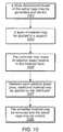
- FIG. 10illustrates a flowchart of a method for making an implant, according to an embodiment.
- FIGS. 11A-11Dillustrate various views of an implant handler, according to an embodiment.
- FIG. 12illustrates an implant handler gripping an implant, according to an embodiment.
- FIG. 13illustrates a flowchart of a method for implanting a spinal implant, according to an embodiment.
- FIG. 14illustrates a knee replacement implant that includes the web structure, according to an embodiment.
- FIG. 15illustrates a hip replacement implant that includes the web structure, according to an embodiment.
- FIG. 16illustrates a long bone reconstruction implant that includes the web structure, according to an embodiment.
- FIG. 17illustrates a cranio-maxifacial implant that includes the web structure, according to an embodiment.
- FIG. 18illustrates a truss structure disposed on an implant, according to an embodiment.
- FIG. 19illustrates a cut made into a boney structure, according to an embodiment.
- FIG. 20illustrates a cutting member, according to an embodiment.
- FIGS. 21-22illustrate a plurality of truss structures disposed on an implant, according to an embodiment.
- FIG. 23illustrates various types of truss structures disposed on an implant, according to an embodiment.
- FIG. 24is a flowchart that illustrates a method of implanting an implant, according to an embodiment.
- FIGS. 1A-1Billustrate views of implant 100 , according to an embodiment.
- Implant 100may be used, for example, in anterior lumbar inter-body fusion (ALIF) or posterior lumbar inter-body fusion (PLIF).
- implant 100may include a web structure 101 with one or more trusses 102 (e.g., planar and space trusses).
- Implant 100 and its web structure 101may be used in various types of implants for humans or animals such as spinal implants (e.g., see FIGS. 1A-2D and 5 A- 6 D)), corpectomy devices (e.g., see FIGS. 2C-2D ), knee replacements (e.g., see FIG. 14 ), hip replacements (e.g., see FIG. 15 ), long bone reconstruction scaffolding (e.g., see FIG. 16 ), and cranio-maxifacial implants (e.g., see FIG. 17 ).
- Other implant usesare also contemplated.
- Trussis a structure having one or more elongate struts connected at joints referred to as nodes. Trusses may include variants of a pratt truss, king post truss, queen post truss, town's lattice truss, planar truss, space truss, and/or a tardendeel truss (other trusses may also be used). Each unit (e.g., region having a perimeter defined by the elongate struts) may be referred to as a “truss unit.”
- planar trussis a truss structure where all of the struts and nodes lie substantially within a single two-dimensional plane.
- a planar trussmay include one or more “truss units” where each of the struts is a substantially straight member such that the entirety of the struts and the nodes of the one or more truss units lie in substantially the same plane.
- a truss unit where each of the struts is a substantially straight member such that the entirety of the struts and the nodes of the truss units lie in substantially the same planeis referred to as a “planar truss unit.”
- space trussis a truss having struts and nodes that are not substantially confined in a single two-dimensional plane.
- a space trussmay include two or more planar trusses (e.g., planar truss units) wherein at least one of the two or more planar trusses lies in a plane that is not substantially parallel to a plane of at least one or more of the other two or more planar trusses.
- a space trussmay include two planar truss units adjacent to one another (e.g., sharing a common strut) wherein each of the planar truss units lie in separate planes that are angled with respect to one another (e.g., not parallel to one another).
- a “triangular truss”is a structure having one or more triangular units that are formed by three straight struts connected at joints referred to as nodes.
- a triangular trussmay include three straight elongate strut members that are coupled to one another at three nodes to from a triangular shaped truss.
- a “planar triangular truss”is a triangular truss structure where all of the struts and nodes lie substantially within a single two-dimensional plane.
- Each triangular unitmay be referred to as a “triangular truss unit.”
- a triangular truss unit where each of the struts is a substantially straight member such that the entirety of the struts and the nodes of the triangular truss units lie in substantially the same planeis referred to as a “planar triangular truss unit.”
- a “triangular space truss”is a space truss including one or more triangular truss units.
- the trusses 102 of web structure 101may include one or more planar truss units (e.g., planar triangular truss units) constructed with straight or curved/arched members (e.g., struts) connected at various nodes.
- the trusses 102may be micro-trusses.
- a “micro-truss”may include a truss having dimensions sufficiently small enough such that a plurality of micro-trusses can be assembled or other wise coupled to one another to form a web structure having a small enough overall dimension (e.g., height, length and width) such that substantially all of the web structure can be inserted into an implant location (e.g., between two vertebra).
- the diameters of the struts forming the micro-trussmay be between about 0.25 millimeters (mm) and 5 mm in diameter (e.g., a diameter of about 0.25 mm, 0.5 mm, 0.6 mm, 0.7 mm, 0.8 mm, 0.9 mm, 1 mm, 2 mm, 3 mm, 4 mm, or 5 mm).
- a micro-trussmay have an overall length or width of less than about 1 inch (e.g., a length less than about 0.9 in, 0.8 in, 0.7 in, 0.6 in, 0.5 in, 0.4 in, 0.3 in, 0.2 in, 0.1 in).
- web structure 101may extend throughout implant 100 (including the central portion of implant 100 ) to provide support throughout implant 100 .
- Trusses 102 of implant 100may thus support implant 100 against tensile, compressive, and shear forces.
- the web structure of trusses 102may also reinforce implant 100 along multiple planes.
- the external truss structuremay, for example, provide support against tensile and compressive forces acting vertically through the implant, and the internal web structure may provide support against tensile, compressive, and shear forces along the various planes containing the respective trusses.
- the web structureincludes trusses 102 that form a triangulated web structure with multiple struts (e.g., struts 103 a - f ) (struts are generally referred to herein as “struts 103 ”).
- web structure 101 of the implant 100may include an internal web structure that is at least partially enclosed by an external truss structure.
- web structure 101may include an internal web structure that includes a space truss having at least a portion of the space truss surrounded by an external truss structure that includes one or more planar trusses formed with a plurality of planar truss units that lie substantially in a single plane.
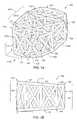
- FIG. 1Adepicts an embodiment of implant 100 and web structure 101 that includes internal web structure 104 and an external truss structure 105 .
- internal web structure 104includes a space truss defined by a plurality of planar truss units 106 coupled at an angle with respect to one another such that each adjacent truss unit is not co-planar with each adjacent truss units.
- Adjacent truss unitsmay include two truss units that share a strut and the respective two nodes at the ends of the shared strut.
- external truss structure 105includes a plurality of planar trusses that are coupled about an exterior, interior or other portion of the implant.
- the external truss structure 105includes a series of planar trusses 107 a,b that are coupled to one another.
- Each planar truss 107 a,bincludes a plurality of planar truss units 108 that are coupled to one another and lie substantially in the same plane.
- planar truss 107 aincludes four triangular planar truss units 108 having a common vertex 110 and arranged to form a generally rectangular structure that lies in a single common plane 109 .
- the four truss unitsare arranged to form a substantially rectangular structure having “X” shaped struts extend from one corner of the rectangular structure to the opposite corner of the rectangular structure.
- the substantially rectangular structuremay include a trapezoidal shape.
- the trapezoidal shapemay be conducive to providing an implant including lordosis.
- Lordosismay include an angled orientation of surfaces (e.g., top and bottom) of an implant that provides for differences in thickness in anterior and posterior regions of the implant such that the implant is conducive for supporting the curvature of a vertebral column.
- planar trusses that form the external trussare coupled to one another, and are aligned along at least one axis.
- planar truss section 107 ais coupled to an adjacent planar truss 107 b .
- Planer truss sections 107 a,bare not parallel in all directions.
- Planar truss sections 107 a,bare, however, arranged parallel to one another in at least one direction (e.g., the vertical direction between the top and the bottom faces of implant 100 ).
- planar trusses 107 a,b and the additional planar trussesare arranged in series with an angle relative to one another to form a generally circular or polygon shaped enclosure having substantially vertical walls defined by the planar trusses and the planar truss units arranged in the vertical direction.
- the external truss portionmay encompass the sides, top, and/or bottom of the implant.
- the external truss portionmay include a top region, side regions, and/or a bottom region.
- FIG. 1Adepicts an embodiment of implant 100 wherein external truss portion 105 includes a top 111 , bottom 112 and a side region 113 .
- side region 113includes a series of planar trusses arranged vertically to form a circular/polygon ring-like structure that completely or at least partially surrounds the perimeter of the space truss disposed in the central portion of implant 100 .
- top portion 111 of external truss structure 105includes a plurality of truss units coupled to one another to form a planar truss that cover substantially all of the top region of internal web structure 104 .
- the top portion 111spans entirely the region between top edges of the side portion 113 of external truss structure 105 .
- top portion 111is formed from a single planar truss that includes a plurality of truss units that lie in substantially the same plane. In other words, the planar truss of top portion 111 defines a generally flat surface.
- the underside of implant 100may include the bottom portion 112 having a configuration similar to that of the top portion 111 .
- external truss structure 105may include a partial side, top and/or bottom external truss portions. Or may not include one or more of the side, top and bottom external truss portions.
- FIG. 2Cdepicts an embodiment of implant 100 than includes an internal web structure 104 that includes a space truss, and does not have an external truss structure.
- implant 100may include a biocompatible material such as a titanium alloy (e.g., ⁇ Titanium Aluminides), cobalt, chromium, stainless steel, Polyetheretherketone (PEEK), ceramics, etc. Other materials are also contemplated.
- implant 100may be made through a rapid prototyping process (e.g., electron beam melting (EBM) process) as further described below.
- EBMelectron beam melting
- Other processesare also possible (e.g., injection molding, casting, sintering, selective laser sintering (SLS), Direct Metal Laser Sintering (DMLS), etc).
- SLSmay include laser-sintering of high-performance polymers such as that provided by EOS of North America, Inc., headquartered in Novi, Mich., U.S.A.
- High-performance polymersmay include various forms of PEEK (e.g., HP3 having a tensile strength of up to about 95 mega Pascal (MPa) and a Young's modulus of up to about 4400 MPa and continuous operating temperature between about 180° C. (356° F.) and 260° C. (500° F.)).
- Other materialsmay include PA 12 and PA 11 provided by EOS of North America, Inc.
- the trussesmay form a triangulated web structure with multiple struts 103 .
- the web structuremay include a pattern of geometrical building blocks.
- the geometrical building blocksmay include triangles.
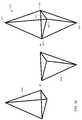
- the geometrical building blocksmay include polyhedrons such as tetrahedrons (e.g., see tetrahedrons 300 a,b in FIG. 3 ), pentahedrons, hexahedrons, heptahedrons (e.g., see heptahedron 801 in FIG. 8A ) and pyramids (e.g., see pyramids 705 a,b in FIG.
- FIG. 7Aheptahedrons 705 a,b in FIG. 7B ), octahedrons (e.g., see octahedron 803 in FIG. 8B ), dodecahedrons (e.g., see dodecahedrons 700 a,b in FIG. 7C ), and icosahedrons (e.g., see icosahedron 805 in FIG. 8C ).
- Other geometrical building blocksare also contemplated (e.g., spherical fifflerenes 807 in FIG. 8D ).
- the space truss of the web structuremay connect multiple midpoints of tetrahedron building blocks and include a regular pattern of tetrahedron blocks arranged adjacent one another.
- the web structuremay not include a pattern of geometrical building blocks.
- FIG. 9illustrates an irregular pattern of struts 103 that may be used in implant 100 .
- Other web structuresare also contemplated.
- FIGS. 3A-3Billustrate a web structure formed with triangular-shaped building blocks, according to an embodiment.
- the triangular shaped building blocksmay form tetrahedrons 300 a,b that may also be used as building blocks (other patterns from the triangles are also contemplated).
- Other building blocksare also contemplated (e.g., square-shaped building blocks).
- a web structuremay include a single tetrahedron, such as tetrahedron 300 a or 300 b alone or in combination with one or more other web structures.
- web structure 313may include two or more tetrahedrons 300 a,b .
- Tetrahedron 300 amay include four triangular faces in which three of the four triangles meet at each vertex.
- two tetrahedrons 300 a and 300 bmay be placed together at two adjacent faces to form web structure 313 with a hexahedron-shaped frame (including six faces).
- Hexahedron-shaped web structure 313may include first vertex 301 , second vertex 309 , third vertex 303 , fourth vertex 305 , and fifth vertex 307 .
- Common plane 311may be shared by two tetrahedrons (e.g., common plane 311 may include third vertex 303 , fourth vertex 305 , and fifth vertex 307 ) to form a hexahedron with first vertex 301 and second vertex 309 spaced away from common plane 311 .
- the center portion of the triangular shaped building blocksmay have a void region in their center that does not include any additional members (e.g., no members other than the struts forming the triangular shaped building blocks) extending there through.
- multiple hexahedron-shaped web structures 313may be arranged in a side-by-side manner.
- Two web structures 313 of implant 100may be connected via their first vertices 301 a,b through strut 103 r and connected via their second vertices 309 a,b through strut 103 t .
- two web structures 313may be connected via their first vertices 301 c,d through strut 103 p and connected via their second vertices 309 c,d through strut 103 s .
- Other connectionsare also possible.
- web structures 313may connect directly through side vertices (e.g., directly through corresponding vertices (such as vertices 303 a,b ) and/or share a common strut (such as strut 103 u )) and/or through a side face (e.g., side faces 111 a,b ).
- Other strutsare also shown (e.g., struts 103 v , 103 w ).
- FIG. 4Aillustrates additional struts 103 (e.g., struts 103 p and 103 r ) connecting the first vertices (represented respectively by 301 a , 301 b , 301 c , and 301 d ) of four hexahedron-shaped web structures 313 in implant 100 .
- FIG. 4Billustrates additional struts 103 (e.g., struts 103 s and 103 t ) connecting second vertices 309 (represented respectively by 309 a , 309 b , 309 c , and 309 d ) of four hexahedron-shaped web structures 313 in implant 100 .
- additional struts 103may also be used internally between one or more vertices of the web structures to form additional trusses (e.g., see web structures in FIGS. 1A-2B ) (other structures are also possible).
- top surface 115 a and bottom surface 115 b of implant 100may include triangles, squares, circles or other shapes (e.g., a random or custom design). Top and bottom surfaces 115 a,b may be used to connect the top and bottom vertices of various geometrical building blocks used in the web structure of implant 100 . For example, each vertex may be connected through struts to the neighboring vertices of other geometrical building blocks. Top surface 115 a may include other strut networks and/or connections. In some embodiments, bottom surface 115 b may mirror the top surface (and/or have other designs). In some embodiments, top surface 115 a and bottom surface 115 b may engage respective surfaces of two adjacent vertebrae when implant 100 is implanted.
- implant 100may include lordosis (e.g., an angle in top and/or bottom surfaces 115 a,b approximately in a range of 4 to 15 degrees (such as 4, 5, 6, 7, 8, 9, 10, 11, 12, 13, 14, or 15 degrees)) to further support the adjacent vertebrae when implanted.
- lordosismay include an angled orientation of surfaces (e.g., top and bottom) that provide for differences in thickness in the anterior and posterior portions of the implant such that the implant is conducive for supporting the curvature of a vertebral column.
- the thickness of implant 100is greater at or near the anterior portion 118 and lesser at or near the posterior portion 120 of the implant.
- the side portions of external truss structure 105are arranged substantially vertically, and the lordosis is formed by the angles of the top portion 111 and bottom portion 112 of external truss structure 105 .
- top portion 111 and bottom portion 112 of external truss structure 105are not perpendicular to the vertical plane defined by the side portion 113 . Rather, the top portion 111 and bottom portion 112 are arranged with an acute angle relative to the vertical plane of side portion 113 at or near the anterior region 118 of implant 100 and with an obtuse angle relative to the vertical plane of side portion 113 at or near posterior region 120 of implant 100 .
- the vertical struts 103 that form the planar truss of side portion 113 of external truss structure 105 proximate posterior region 120 of implant 100are shorter than struts 103 that form side portion 113 of external truss structure 105 proximate anterior region 118 of implant 100 .
- the struts 103 forming the “X” cross members of the side planar trusses proximate the posterior region 120 of implant 100are shorter than struts forming the “X” cross members of the side planar trusses proximate the anterior region 118 of implant 100 .
- top and bottom external truss portionsmay be non-perpendicular to the side portions of the external truss proximate the anterior and posterior portions of the implant.
- the side, top, and/or bottom portionsmay include multiple planar trusses angled relative to one another in any orientation.
- the top or bottom portionsmay include four planar trusses, each formed of multiple truss units, such that the portion(s) includes a pyramidal like shape.
- the implantmay not include lordosis.
- FIGS. 2A-2Billustrate two views of an embodiment of an implant 200 without lordosis.
- the top surface and bottom surfacemay not include connecting struts.
- FIGS. 2C-2Dillustrate two views of implant 250 without outer struts (e.g., without external truss portions formed of planar trusses).
- implant 250includes internal web structure 104 (e.g., a space truss) and does not include an external truss structure.
- the exterior faces of implant 250are defined by a plurality of truss units that are angled relative to each of its adjacent truss units.
- the relative alignment of the truss unitsresults in a non-planar exterior that includes a plurality of pointed junctions.
- the pointed junctionse.g., pointed junction 201
- the pointed junctionsmay operate to dig into the surrounding bone to hold the implant in place (for example, if the implant is being used in a corpectomy device).
- FIGS. 5A-5Cillustrate progressive sectioned views of implant 100 showing the internal structure of implant 100 , according to an embodiment.
- FIG. 5Aillustrates a sectioned view of a lower portion of implant 100 .
- Bottom surface 115 bis shown with various struts (e.g., struts 103 ) extending upward from bottom surface 115 b .
- FIG. 5Billustrates a sectioned view approximately mid-way through implant 100 .
- Strutssuch as struts 103 e - f , shared by various stacked tetrahedrons in the web structure are shown. Some struts extend through central portion 501 a and/or 501 b of implant 100 .
- FIG. 5Aillustrates a sectioned view of a lower portion of implant 100 .
- Bottom surface 115 bis shown with various struts (e.g., struts 103 ) extending upward from bottom surface 115 b .
- central portion 501 amay include a rectangular region that has a width of approximately 50% of the implant width, a height of approximately 50% of the implant height, and a length of approximately 50% of the implant length and located in the center of implant 100 .
- central portion 501 bmay encompass a region (e.g., a spherical region, square region, etc.) of approximately a radius of approximately 1 ⁇ 8 to 1 ⁇ 4 of the width of implant 100 around a position located approximately at one half the width, approximately one half the length, and approximately one-half the height of implant 100 (i.e., the center of implant 100 ).
- Other central portionsare also contemplated.
- the central portionmay include a square region with a length of one of the sides of the square region approximately 1 ⁇ 4 to 1 ⁇ 2 the width of implant 100 around a position approximately at one half the width, approximately one half the length, and approximately one half the height of the implant.
- An example height 502 a , width 502 b , and length 502 cis shown in FIG. 5D .
- the heightmay be up to about 75 mm or more.
- the width and/or lengthcould be approximately 7 inches or longer.
- the width, length, and/or heightmay vary along implant 100 (e.g., the height may vary if the implant includes lordosis).
- the heightmay be taken at one of the opposing sides, the middle, and/or may be an average of one or more heights along the length of implant 100 .
- the web structuremay extend through central portion 501 a,b of the implant (e.g., at least one strut of the web structure may pass at least partially through central portion 501 a,b ).
- FIG. 5Cillustrates another sectioned view showing sectioned views of top tetrahedrons in the web structure.
- FIG. 5Dshows a complete view of implant 100 including top surface 115 a with vertices 301 a - d.
- FIGS. 6A-6Dillustrate alternate embodiments of implant 100 .
- different sections of the hexahedron-shaped geometric designmay be used.
- the bottom half of the hexahedron-shaped geometric designmay be used (primarily including the lower tetrahedron structures).
- design 600may be expanded proportionately to have similar overall dimensions as the hexahedron-shaped geometric design (e.g., the tetrahedrons may be expanded to approximately twice the height of the tetrahedrons in the hexahedron-shaped geometric design to give design 600 a height approximately the same as the hexahedron-shaped geometric design).
- design 600may also be angled (e.g., on top surface 601 a and/or bottom surface 601 b ) to provide design 600 with lordosis to, in some embodiments, have a better fit between the vertebral endplates.
- Top surface 601 a and/or bottom surface 601 bmay also include struts to connect nodes of design 600 (e.g., see the strut network on the top surface in FIG. 6 a ). Other patterns of struts for top surface 601 a and/or bottom surface 601 b may also be used.
- design 600may not include negative angles between struts and may thus be easier to create through a casting or molding process.
- FIGS. 6C-6Dillustrate another alternate embodiment of implant 100 .
- approximately the middle 40 to 60 percent of the hexahedron-shaped geometric designmay be used.
- an overall height of the hexahedron-shaped geometric designis approximately 37 mm
- approximately the bottom 10 mm and approximately the top 10 mm of the designmay be removed and approximately the middle 17 mm of the design may be used for the implant.
- Middle portion design 650may then be expanded proportionately such that the approximate height of the expanded design may be approximately 37 mm (or a different height as needed).
- Top surface 651 a and bottom surface 651 bmay include a network of struts (e.g., see the struts on top surface 651 a of FIG.
- FIG. 6Cother networks of struts are also contemplated.
- Other portions of the design for the implantare also contemplated (e.g., the top half of the design shown in FIG. 1A , the bottom half of the design shown in FIG. 1A , etc).
- Design portionsmay be proportionately expanded to meet specified dimensions (e.g., specified height, width, and length).
- the amount of strutsmay be reduced or material in the implant may be redistributed so that some struts may have a larger diameter and some may have a smaller diameter (e.g., the different diameters may reinforce against different directional forces).
- a partial-design cagemay be used (e.g., with half of the web structure so that the structure includes a tetrahedron.
- the implantmay include angled surfaces (e.g., an angled top surface 651 a and/or angled bottom surface 651 b ) to provide lordosis for implants to be implanted between the vertebral endplates.
- the web structure of implant 100may distribute forces throughout implant 100 when implanted.
- the connecting struts of the web structuremay extend throughout the core of implant 100 , and the interconnectivity of struts 103 may disperse the stress of compressive forces throughout implant 100 to reduce the potential of stress risers (the distribution of forces throughout implant 100 may prevent concentration of stress on one or more portions of the vertebrae that may otherwise result in damage to the vertebrae).
- the web structure of implant 100may also provide surface area for bone graft fusion.
- the web structure extending throughout implant 100may add additional surface areas (e.g., on the surface of the struts making up implant 100 ) to fuse to the bone graft material and prevent bone graft material from loosening or migrating from implant 100 .
- the web structuremay also support bone in-growth.
- adjacent bonee.g., adjacent vertebrae if the implant is used as a spinal implant
- the bone growth and engagement between the bone growth and implant 100may further stabilize implant 100 .
- the surfaces of implant 100may be formed with a rough surface to assist in bone in-growth adhesion.
- struts 103may have a diameter approximately in a range of about 0.025 to 5 millimeters (mm) (e.g., 1.0 mm, 1.5 mm, 3 mm, etc). Other diameters are also contemplated (e.g., greater than 5 mm).
- the strutsmay have a length approximately in a range of 0.5 to 20 mm (e.g., depending on the implant size needed to, for example, fit a gap between vertebral endplates).
- strutsmay have a length approximately in a range of 30-40 mm for a hip implant.
- the reduced strut size of the web structuremay allow the open cells in implant 100 to facilitate bone growth (e.g., bone may grow through the open cells once implant 100 is implanted in the body).
- Average subsidence for implantsmay be approximately 1.5 mm within the first 3 weeks post op (other subsidence is also possible (e.g., approximately between 0.5 to 2.5 mm)).
- a strut size that approximately matches the subsidencee.g., a strut size of approximately 1.5 mm in diameter and a subsidence of approximately 1.5 mm
- the net 0 impedance throughout the entire surface area of the implant/vertebrae endplate interfacemay result in a larger fusion column of bone that may result in more stable fusion.
- Other fusion column sizesare also contemplated.
- the configuration of the implant 100may redistribute the metal throughout the implant 100 .
- a rimmay not be included on the implant 100 (in some embodiments, a rim may be included).
- the resulting bone growth(e.g., spinal column) may grow through the implant 100 .
- greater than 50% of the interior volume of implant 100may be open. In some embodiments, greater than 60%, greater than 70%, and/or greater than 80% of implant 100 may be open (e.g., 95%). In some embodiments, the open volume may be filled with bone growth material. For example, cancellous bone may be packed into an open/internal region of implant 100 .
- At least a portion of the surfaces of implant 100may be coated/treated with a material intend to promote bone growth and/or bone adhesion and/or an anitmicrobial agent to prevent infections.
- the surface of the strutse.g., struts 103 forming the web structure
- a biologicmay include a coating, such as hydroxyapatite, bone morphaginic protein (BMP), insulinlike growth factors I and II, transforming growth factor-beta, acidic and basic fibroblast growth factor, platelet-derived growth factor, and/or similar bone growth stimulant that facilitates good biological fixation between the bone growth and a surface of the implant.
- BMPbone morphaginic protein
- insulinlike growth factors I and IIinsulinlike growth factors I and II
- transforming growth factor-betatransforming growth factor-beta
- acidic and basic fibroblast growth factortransforming growth factor-beta
- platelet-derived growth factorplatelet-derived growth factor
- similar bone growth stimulantthat facilitates good biological fixation between the bone growth and a surface of the implant.
- a bone growth factormay include a naturally occurring substance capable of stimulating cellular growth, proliferation and cellular differentiation (e.g., a protein or steroid hormone).
- a biologic and/or growth factormay be secured to a central region of implant 100 .
- a biologic or growth factormay be provided on at least a portion of a strut that extends through central portion 501 a and/or 501 b of implant 100 .
- Such an embodimentmay enable the delivery of a biologic and or a growth factor to a central portion of an implant.
- the biologic or growth factormay be physically secured to a strut in a central portion of implant 100 as opposed to being packed into an open volume that does not include a strut provided therein for the physical attachment of the biologic and/or growth factor.
- subsidencemay place additional pressure on the bone graft material (which may already be under compressive forces in implant 100 ) and act to push the bone graft material toward the sides of implant 100 (according to Boussinesq's theory of adjacent material, when a force is applied to a member that is adjacent to other materials (such as sand, dirt, or bone graft material) the force against the member creates a zone of increased pressure (e.g., 60 degrees) in the adjacent material).
- Struts 103 of the web structuremay resist bone graft material protrusion from the sides of the web structure and may increase the pressure of the bone graft material.
- Bone graft materialmay need to be implanted in a higher-pressure environment to create an environment conducive to strong bone growth (e.g., according to Wolf's law that bone in a healthy person or animal will adapt to the loads it is placed under).
- the web structuremay thus increase the chance of stronger fusion.
- FIG. 7Aillustrates a web structure formed with two pyramids, according to an embodiment.
- the geometric building blocks for implant 100include pyramids.
- top/upper pyramid 705 a and bottom/lower pyramid 705 bmay be joined to form a octahedron building block 703 .
- the octahedron building blocks 703may be joined, for example, at a face (e.g., a base 706 of the top and bottom pyramids 705 a and 705 b ) by sharing a surface, etc.
- one or both of top and bottom pyramid 705 a,bmay include a square pyramid.
- the resulting octahedronthus includes two opposing pyramid shaped truss structures that share a common square shaped truss unit at their base (e.g., where the two bases of the pyramids meet).
- the geometric building blockmay include one or more additional struts extending through an interior region defined by the faces of the building blocks.
- the octahedron building block formed from top and lower pyramids 705 a,binclude two struts 103 a extending diagonally between opposing vertices of the face (e.g., the square shaped truss unit) shared by top and lower pyramids 705 a,b , and having an intersection 710 .
- the opposing verticesare directly connected by one or more struts arranged in a substantially straight line between each pair of the opposing vertices.
- struts 103 amay be formed from four separate strut sections that extend from each respective vertex to intersection 710 .
- the illustrated embodimentalso includes an additional central strut 103 b that extends between vertices 701 , 709 of top and bottom pyramids 705 a,b , and that intersects struts 103 a at or near intersection 710 .
- strut 103 bmay be formed from one or two separate strut sections that extend from each respective vertex 701 , 709 of top and bottom pyramids 705 a,b to intersection 710 . Accordingly, the opposing vertices of the octahedron that do not lie in the common face (e.g.
- struts 103 a,bmay include any combination of struts 103 a,b .
- one embodimentmay include only one or two of struts 103 a extending between opposing vertices of the square shaped common truss unit and without strut 103 b .
- one embodimentmay include only two opposing vertices of the square shaped common truss unit being connected to one another via a strut.
- One embodimentmay include only strut 103 b extending between the opposing vertices of the octahedron without struts 103 a.
- FIG. 7Billustrates a web structure formed with two heptahedrons, according to an embodiment.
- the geometric building blocks for implant 100include heptahedrons.
- top/upper heptahedron 705 a and bottom/lower heptahedron 705 bmay be joined to form a dodecahedron building block 703 .
- the dodecahedron building blocks 703may be joined, for example, at a face (e.g., their bases) by sharing a side surface, etc.
- Embodimentsmay include additional members, such as struts 103 a,b that extend between vertices of the heptahedron 705 a,b in a manner similar to that described with respect to FIG. 7A .
- FIG. 7Cillustrates a web structure formed with two dodecahedrons, according to an embodiment.
- top/upper dodecahedron 705 a and bottom/lower dodecahedron 705 bmay be joined to form a 22-sided polyhedron building block 703 .
- the 22-sided polyhedron building blocks 703may be joined, for example, at a face by sharing a side surface, etc.
- Embodimentsmay include additional members, such as struts 103 a,b that extend between vertices of the dodecahedrons 705 a,b in a manner similar to that described with respect to FIG. 7A .
- the trussesmay include a series of packing triangles, a two-web truss, a three-web truss, etc.
- the web structure for implant 100may include one or more trusses as described in U.S. Pat. No. 6,931,812 titled “Web Structure and Method For Making the Same”, which issued Aug. 23, 2005, which is hereby incorporated by reference in its entirety as though fully and completely set forth herein.
- FIG. 10illustrates a flowchart of a method for making implant 100 .
- implant 100may be made through rapid prototyping (e.g., electron beam melting, laser sintering, etc). It should be noted that in various embodiments of the methods described below, one or more of the elements described may be performed concurrently, in a different order than shown, or may be omitted entirely. Other additional elements may also be performed as desired. In some embodiments, a portion or the entire method may be performed automatically by a computer system.
- a three dimensional model of implant 100may be generated and stored in a storage medium accessible to a controller operable to control the implant production process.
- a layer of materiale.g., a powder, liquid, etc.
- the powdermay include ⁇ TiAl ( ⁇ Titanium Aluminides) which may be a high strength/low weight material. Other materials may also be used.
- the powdermay be formed using a gas atomization process and may include granules with diameters approximately in a range of 20 to 200 micrometers ( ⁇ m) (e.g., approximately 80 ⁇ m).
- the powdermay be delivered to the support through a distributer (e.g., delivered from a storage container).
- the distributer and/or the supportmay move during distribution to apply a layer (e.g., of powder) to the support.
- the layermay be approximately a uniform thickness (e.g., with an average thickness of 20 to 200 micrometers ( ⁇ m)).
- the distributer and supportmay not move (e.g., the material may be sprayed onto the support).
- the controllermay move an electron beam relative to the material layer.
- the electron beam generatormay be moved, and in some embodiments the support may be moved.
- a melting temperature approximately in a range of 1200 to 1800 degrees Celsiusmay be obtained between the electron beam and the material.
- additional materialmay be applied by the distributer.
- implant 100may be cooled (e.g., using a cool inert gas).
- the edges of the implantmay be smoothed to remove rough edges (e.g., using a diamond sander).
- the implantmay include rough edges to increase friction between the implant and the surrounding bone to increase adhesion of the implant to the bone.
- implant 100may be cast or injection molded.
- multiple partsmay be cast or injection molded and joined together (e.g., through welding, melting, etc).
- individual struts 103 forming implant 100may be generated separately (e.g., by casting, injection molding, etc.) and welded together to form implant 100 .
- multiple implants of different sizesmay be constructed and delivered in a kit. A medical health professional may choose an implant (e.g., according to a needed size) during the surgery. In some embodiments, multiple implants may be used at the implant site.
- FIGS. 11A-11Dillustrate various views of implant handler 1100 , according to an embodiment.
- handler 1100may include jaws 1107 to grip and release implant 100 . Jaws 1107 may be operated by trigger 1109 coupled to cam 1115 that acts to push block 1101 when trigger 1109 is pushed away from handle 1117 .
- leaf spring 1111may act to push trigger 1109 away from handle 1117 .
- block 1101As block 1101 is pushed by cam 1115 , block 1101 may push against compression spring 1103 and shaft 1105 (which may be flexible shaft inside tube 1119 ). Shaft 1105 may push against jaws 1107 and push them open (see FIG. 11D ).
- shaft 1105may also be pulled with block 1101 toward handle 1117 (in some embodiments, shaft 1105 may be coupled to block 1101 ). As shaft 1105 is pulled toward handle 1117 , shaft 1105 may pull jaws 1107 closed (e.g., see FIGS. 11 c and 12 ) such that struts of implant 100 may be gripped in grooves 1119 in jaws 1107 (e.g., see FIG. 12 which illustrates handler 1100 gripping implant 100 ). In some embodiments, block 1201 (see FIG.
- Handler 1100is one embodiment of a handler for implant 100 ; other handlers and handler types are also contemplated.
- FIG. 13illustrates a flowchart of a method for implanting a spinal implant, according to an embodiment. It should be noted that in various embodiments of the methods described below, one or more of the elements described may be performed concurrently, in a different order than shown, or may be omitted entirely. Other additional elements may also be performed as desired. In some embodiments, a portion or the entire method may be performed automatically by a computer system.
- an intersomatic spacemay be accessed.
- an anterior openingmay be made in a patient's body for an anterior lumbar inter-body fusion (ALIF) approach or a posterior opening may be made for a posterior lumbar inter-body fusion (PLIF) approach.
- at least a portion of the intersomatic spacemay be excised to form a cavity in the intersomatic space.
- the implantmay be inserted into the cavity in the intersomatic space.
- handler 1100may be used to grip implant 100 .
- forcemay be applied to the implant (e.g., through a hammer) to insert the implant into the cavity.
- trigger 1109 on handler 1100may be released to release implant 100 .
- the implant and/or space in the cavitymay be packed with bone graft material.
- the access point to the intersomatic spacemay be closed (e.g., using sutures).
- FIG. 14illustrates knee replacement implant 1400 that includes a web structure, according to an embodiment.
- portions of knee replacement implant 1400may include a web structure to, for example, increase bone graft fusion with surrounding bone (e.g., along portions of implant 1400 that are anchored in the bone).
- Portion 1401 a and 1401 bmay include the web structure for bone in-growth to further support and secure the knee implant.
- Other portions of knee implant 1400may also include a web structure.
- FIG. 15illustrates hip replacement implant 1500 that includes a web structure, according to an embodiment.
- Portions of shaft 1501 of hip implant 1500may include a web structure for bone in-growth along the shaft to support and secure the hip implant 1500 .
- implant 1500may use a web structure in place of (or in addition to) texture along shaft 1501 for securing implant 1500 .
- FIG. 16illustrates long bone reconstruction implant 1600 that includes a web structure, according to an embodiment.
- a web structuremay be used in implant 1600 for securing a long bone (e.g., the femur or tibia).
- the implantmay be fastened to the bone along the bone (e.g., using bone screws 1601 ) to keep the bone segments in place during healing.
- the bonemay also grow into the implant web structure to further secure the implant to the long bone.
- Other bonesare also contemplated (e.g., clavicle, phalanges, metatarsals, etc).
- the implantmay be coated and/or infused with a biologic material to encourage bone growth or an antimicrobial agent to reduce the chance of infection.
- FIG. 17illustrates cranio-maxifacial implant 1700 that includes a web structure, according to an embodiment.
- implant 1700may be used to reconstruct a portion of the jaw.
- the top and bottom surfaces of implant 1700may include additional struts (e.g., as seen in FIG. 1A ) or may include point junctions (e.g., as seen in FIG. 2D ).
- Implant 1700may be secured to the implant site (e.g., through bone screws 1701 ) or may be self securing (e.g., between two or more bones).
- the implantmay be customized.
- three dimensional measurements and/or shape of the implantmay be used to construct an implant that distributes the web structure throughout a three-dimensional shape design.
- the three-dimensional shape design of the implantmay be entered into a computer system/controller that may control the electron beam melting process.
- the truss design and orientationmay be preset or predetermined by the computer system/controller.
- a usermay select the truss design to use (e.g., one or more of truss designs shown in FIG. 3A , 7 A, or 8 A- 9 ) and/or may select the orientation of the trusses in the implant.
- the usermay enter the outer dimensions of the three dimensional shape and the computer system/controller may generate a three-dimensional design that includes the truss design and orientation.
- the computer system/controllermay generate the three-dimensional design by providing a uniform distribution of the truss design throughout a three-dimensional shape with the outer dimensions provided by the user.
- the heights and widths of the trusses used in the designmay be proportional to the overall height and width of the three-dimensional shape (e.g., the trusses may have heights approximately equal to 1 ⁇ 2 the overall height and a width of approximately 1/16 the overall width). Other heights and widths are also contemplated.
- the usermay provide the height and width and/or the computer system/controller may have default heights and widths to use.
- Embodiments of a subset or all (and portions or all) of the abovemay be implemented by program instructions stored in a memory medium or carrier medium and executed by a processor (e.g., a processor on the controller operable to control the implant production process).
- a memory mediummay include any of various types of memory devices or storage devices.
- memory mediumis intended to include an installation medium, e.g., a Compact Disc Read Only Memory (CD-ROM), floppy disks, or tape device; a computer system memory or random access memory such as Dynamic Random Access Memory (DRAM), Double Data Rate Random Access Memory (DDR RAM), Static Random Access Memory (SRAM), Extended Data Out Random Access Memory (EDO RAM), Rambus Random Access Memory (RAM), etc.; or a non-volatile memory such as a magnetic media, e.g., a hard drive, or optical storage.
- the memory mediummay comprise other types of memory as well, or combinations thereof.
- the memory mediummay be located in a first computer in which the programs are executed, or may be located in a second different computer that connects to the first computer over a network, such as the Internet. In the latter instance, the second computer may provide program instructions to the first computer for execution.
- the term “memory medium”may include two or more memory mediums that may reside in different locations, e.g., in different computers that are connected over a network.
- a computer system at a respective participant locationmay include a memory medium(s) on which one or more computer programs or software components according to one embodiment of the present invention may be stored.
- the memory mediummay store one or more programs that are executable to perform the methods described herein.
- the memory mediummay also store operating system software, as well as other software for operation of the computer system.
- a truss/web structuremay be disposed on at least a portion of an implant to facilitate coupling of the implant to an adjacent structure.
- one or more truss structuresmay be disposed on and/or extend from a surface (e.g., an interface plate) of the implant that is intended to contact, and at least partially adhere to, the bony structure during use.
- a surfacee.g., an interface plate
- one or more truss structuresmay be disposed on a contact surface of the intervertebral implant to facilitate bone growth that enhances coupling of the intervertebral implant to the bony structure.
- a truss structuremay include one or more struts that extend from the contact surface to define an open space for bone growth therethrough, thereby enabling bone through growth to interlock the bone structure and the truss structure with one another to couple the implant to the bony structure at or near the contact face.
- Such interlocking bone through growthmay inhibit movement between the implant and the bony structure which could otherwise lead to loosening, migration, subsidence, or dislodging of the implant from the intended position.
- Similar techniquesmay be employed with various types of implants, including those intended to interface with tissue and/or bone structures.
- a truss structuremay be employed on a contact surface of knee implants, in a corpectomy device, in a hip replacement, in a knee replacement, in a long bone reconstruction scaffold, or in a cranio-maxifacial implant hip implants, jaw implant, an implant for long bone reconstruction, foot and ankle implants, shoulder implants or other joint replacement implants or the like to enhance adherence of the implant to the adjacent bony structure or tissue.
- FIG. 18depicts an embodiment of an implant 1800 in accordance with one or more embodiments of the present technique.
- implant 1802may include a spinal implant, a knee implant, a hip implant, a jaw implant, an implant for long bone reconstruction, or the like.
- implant 1800may include an intervertebral implant that is to be implanted between end plates of two adjacent vertebras during a spinal implant procedure.
- implant 1800may include a fusion implant (e.g., a fusion cage) intended to rigidly fix the relative positions of the two adjacent vertebrae, or and dynamic intervertebral device intended to couple to each of the two adjacent vertebrae and to facilitate motion (e.g., flexion, extension, and/or lateral bending) between the two adjacent vertebrae.
- a fusion implante.g., a fusion cage
- dynamic intervertebral deviceintended to couple to each of the two adjacent vertebrae and to facilitate motion (e.g., flexion, extension, and/or lateral bending) between the two adjacent vertebrae.
- implant 1800includes a body 1802 having two contact faces 1804 a,b .
- contact facerefers to a portion of an implant intended to be in contact or near contact with an adjacent structure (e.g., a bony structure) to adhere/couple with the adjacent structure when implanted.
- a contact surfacemay include an interface plate of an implant, for instance.
- An implantmay include any number of contact faces.
- an implantmay include one or more contact faces intended to couple to one or more adjacent bony structures.
- contact face 1804 amay include an upper contact face intended to contact and secure to a first adjacent bony structure, and 1804 b may include a lower contact face intended to contact and secure to a second adjacent bony structure.
- contact face 1804 amay couple to a portion of the first bony structure disposed above implant 1800 and contact face 1804 b may couple to the second bony structure disposed below implant 1800 .
- the number and orientation of the contact surfacesmay vary based on the intended application, and, thus, relative terms such as upper and lower are intended as exemplary and are not intended to be limiting.
- one or both of the upper and lower contact faces 1804 a,bmay be oriented such that the are disposed laterally (e.g., as right, left, back and/or front sides of implant body 1802 .
- the cubic shape of body 1802is intended to be exemplary and is not intended to be limiting.
- body 1802may include any desirable implant construct such as fusion cages with different shapes or a mechanical construct that allows for motion preservation.
- Contact surface(s)may take any suitable shape, e.g., a substantially flat planar surface, a curved/contoured surface, ridges, or the like.
- a single, a plurality or all of the contact faces of an implantmay include one or more truss structures.
- upper contact face 1804 aincludes a truss structure 1806 disposed thereon.
- Such an embodimentmay be of particular use when implant 1800 is intended to create a fixation for a tibila tray and femoral component for a knee replacement implant or any other joint replacement implant.
- truss structure 1806is illustrated on a single contact surface, other embodiments may include any number of truss structures disposed on any number of contact faces.
- implant 1800may include one or more truss structures 1806 disposed on one or both of upper and lower contact surfaces 1804 a,b .
- Such an embodimentmay be of particular use when implant 1800 is intended to span the distance between two adjacent bony structures (e.g., the end plates of two adjacent vertebrae).
- a truss structureincludes one or more struts that extend from a respective contact surface and defines an opening that enables bone through growth to facilitate coupling of the truss structure and the implant to the honey structure.
- truss structure 1806includes a space truss formed of three struts 1807 a,b,c that each include elongate members each having a first end coupled to contact surface 1804 a and a second end coupled to each of the other struts at a vertex 1810 .
- Each face of the triangular shaped truss structureincludes a planar truss structure having a triangular opening with a perimeter defined by two of struts 1807 a,b,c and the adjacent portion of contact face 1804 a .
- truss structure 1806includes a generally triangular shaped space truss that defines a four sided, substantially open volume 1812 .
- open volume 1812may facilitate bone growth through truss structure 1806 , thereby enhancing coupling of implant 1800 to the adjacent bony structure.
- at least a portion of truss structure 1806is in contact or near contact with the adjacent bony structure, thereby enabling bone growth to extend into and/or through at least a portion of open volume 1812 of truss structure 1806 such that the bone growth interlocks with one or more struts 1808 a,b,c of truss structure 1806 .
- the interlocking of the bone growth and the strutsmay rigidly fix implant 1800 in a fixed location relative to the boney structure.
- implant 1800may be pressed into contact with the adjacent bony structure such that at least a portion of truss structure 1806 is disposed inside of the adjacent bony structure upon implantation.
- implant 1800may be pressed into contact with the adjacent bony structure such that vertex 1810 pierces into the bony structure and is advanced such that at least a portion of struts 1808 a,b,c and open volume 1812 extend into the bony structure.
- Such a techniquemay encourage bone to grow into and/or through open volume 1812 .
- implant 1800may be advanced/pressed into the adjacent bony structure until the respective contact surface (e.g., upper contact surface 1804 a ) is in contact or near contact with the adjacent bony structure.
- At least a portion of the truss structure and/or the contact surfacemay be coated/treated with a material intend to promote bone growth and/or bone adherence and an antimicrobial to prevent infection to the truss structure and/or the contact surface.
- the surface of the struts and/or the contact surfacemay be coated with a biologic and/or a bone growth factor, such as those described herein.
- At least a portion of the adjacent bony structure in which the truss structure is to be implantedmay be pierced/cut/slit prior to truss structure 1806 being advanced/pressed into the adjacent bony structure.
- a cutting tool/edgemay be used to cut into the adjacent bony structure such that the resulting cuts accommodate one or more struts of truss structure 1806 .
- truss structure 1806includes a triangular shape, such as that depicted in FIG. 18
- one or more complementary cutsmay be made into the adjacent bony structure in a complementary pattern.
- FIG. 19illustrates a cut 1820 that may be made into adjacent bony structure 1822 prior to or as a result of truss structure 1806 being advanced/pressed into the adjacent bony structure 1822 .
- FIG. 19may be representative of an end view of a vertebra (e.g., looking upward/downward into the end plate of the vertebrae).
- cut 1820may include one or more segments intended to accommodate one or more struts of truss structure 1806 .
- cut 1820includes three slits 1820 a,b,c formed in bony structure 1822 .
- Slits 1820 a,b,cmay extend from the face of the boney structure into the bony structure in a direction substantially perpendicular to a face of the bony structure and/or substantially parallel to the intended direction of advancement of truss structure 1806 and/or implant 1800 into the bony structure.
- slits 1820 a,b,cinclude cuts into the bone that do not require any boney material to be removed. For example, a sharp cutting edge may be advanced into the bone to create the slit, with no substantial amount of bone being removed.
- struts 1808 a,b,cmay slide into slits 1820 a,b,c , respectively.
- the illustrated embodimentsincludes three slits oriented at approximately one-hundred twenty degrees relative to one another about a vertex 1824 , other embodiments may include any number of slits in any variety of orientation to accommodate one or more struts of a truss structure extending from a contact face of an implant.
- Cut 1820may be complementary to the shape/orientation of struts 1808 of truss structure 1806 .
- cut 1820may include four slits oriented at approximately ninety-degrees relative to one another.
- cut 1820may be formed by one or more complementary cutting members (e.g., knives/blades) that are pressed, slid, or otherwise advanced into honey structure 1822 .
- a cutting memberincludes one or more cutting edges arranged complementary to the profile of the struts of the truss structure such that advancement of the cutting edge cuts one, a plurality, or all of the slits to accommodate the truss structure being advanced/pressed into the bony structure.
- FIG. 20illustrates a cutting member 1830 in accordance with one or more embodiments of the present technique.
- Cutting member 1830includes three cutting blades 1830 a,b,c oriented at approximately one-hundred twenty degrees relative to one another about a vertex 1834 .
- cutting members 1830 a,b,care arranged complementary to slits 1820 a,b,c of cut 1820 and/or struts 1808 a,b,c of truss structure 1806 .
- cutting member 1830may include four cutting blades oriented at approximately ninety-degrees relative to one another.
- the cutting bladesmay be advanced into boney structure 1822 at a depth that is about the same or deeper than the height of truss structure 1806 . In some embodiments, the cutting blades may be advanced into boney structure 1822 at a depth that is about the same or shallower than the height of truss structure 1806 .
- a leading edge of the cutting bladesmay be shaped to be complementary to the shape of the struts. For example, the leading edge of one, a plurality, or all of cutting blades 1830 a,b,c , may be angled similar to the angle of struts 1808 a,b,c extending from contact surface 1804 a , as illustrated by dashed line 1846 .
- cutting member 1830may be provided as an instrument that is advanced into the boney structure. In some embodiments, cutting member 1830 may be integrated with or more other devices used during the implantation procedure. For example, during a spinal implant procedure, cutting member 1830 may be coupled to a distractor typically positioned between the vertebrae and expanded to set the relative positions of the vertebrae. The force of distraction may act to advance the cutting member into the bony structure.
- FIG. 20illustrates a cutting member 1830 is disposed on a top surface 1844 a of a body 1842 of a distractor 1840 , in accordance with one or more embodiments of the present technique.
- one or more cutting membersmay be disposed on other portions of distractor, such as a bottom surface 1844 b .
- distractor 1840may be disposed between the adjacent bony structures and expanded such that top and bottom surfaces 1844 a,b move away from one another, thereby pressing one or more of cutting members 1830 into the adjacent boney structure (e.g., 1822 ) to form one or more cuts (e.g., 1820 ) in the honey structure, where the cuts are intended to accommodate struts (e.g., 1808 a,b,c ) of the truss structure (e.g., e.g., 1806 ) of an implant (e.g., 1800 ) to be engaged with the honey structure.
- strutse.g., 1808 a,b,c
- the distractormay be used to increase a separation distance between two adjacent bony structures (e.g., between end plates of adjacent vertebrae).
- the distractoris unexpanded and/or removed, and the implant (e.g., 1800 ) is disposed between the bony structures (e.g., in substantially the same position as the distractor) such that one or more truss structures are aligned/engaged with one or more of the cuts.
- a plurality of truss structuresmay be provided on one or more contact surfaces of implant 1800 .
- four truss structures 1806 a,b,c,dare disposed substantially adjacent one another on contact surface 1804 a,b of implant 1800 such that one, a plurality, or all of struts of truss structures 1806 a,b,c,d share common vertices at the contact surface 1804 a .
- one, a plurality or all of truss structuresmay be spaced apart from one another.
- one, a plurality, or all of truss structures 1806 a,b,c,dmay not share a vertices at or near contact surface 1804 a .
- any number of truss structuresmay be provided on any portion of implant 1800 .
- the shape and orientation of the truss structuresmay be varied to mimic various desired shapes.
- the truss structuresmay be varied in height to provide a curved profile similar to that of a ball and/or a socket of a joint.
- implant 1800may include a plurality of truss structures stacked upon one another to form a web-like structure disposed on one or more faces of implant 1800 .
- FIG. 22illustrates a multi-layer truss-structure (e.g., web structure) disposed on a contact surface of implant 1800 in accordance with one or more embodiments of the present technique.
- a triangular truss structure 1806 eis stacked atop vertices of truss structures 1806 b,c,d .
- a truss structure provided at a contact surface of an implantmay include a web structure, such as those described with respect to implants 100 , 200 250 , 600 and 650 described herein.
- the shape and orientation of the web structuresmay be varied to mimic various desired shapes.
- the web structuremay be varied in height to provide a curved profile similar to that of a ball and/or a socket of a joint.
- one or more additional strutsmay be provided between one, a plurality, or all of the vertices of truss structures.
- struts 1808 d,e,f,g ,hextend between the vertices of truss structures 1806 a,b,c,d .
- one or more strutsmay extend between a plurality or all of the struts at or near the point where they are coupled to the contact face.
- one or more strutsmay extend in place of one or more of the dashed lines illustrated in FIGS. 18 , 21 , 22 and 23 .
- FIG. 23illustrates a plurality of exemplary truss structures that may be coupled to a contact face of an implant in accordance with one or more embodiments of the present technique.
- a truss structure 1806may include a triangular-shaped planar truss.
- truss structure 1806 aincludes two substantially shaped truss members extending from contact surface 1804 a and coupled to one another at a vertex to define an open region 1812 a through which bone growth may occur.
- Other embodimentsmay include any variety of geometrical truss structure shapes, such as four-sided (e.g., pyramidal), five-sided, six-sided, seven sided (not depicted), and/or eight sided truss structures 1806 b,c,d,e , respectively. Additionally, cubic, rectangular or pentagonal block shaped structures may be used.
- embodimentsmay include any of the truss-structures disclosed herein, such as those disclosed with respect to FIGS. 1A-9 .
- any type, size, number, or combination of number, types and sizes of truss structuresmay be provided on one, a plurality, or all of the contact faces of an implant.
- FIG. 24is a flowchart that illustrates a method 1900 of implanting an implant in accordance with one or more embodiments of the present technique.
- method 1900includes preparing a honey structure, as depicted at block 1902 , and inserting an implant (e.g., 1800 ), as depicted at block 1904 .
- preparing a boney structureincludes positioning the honey structure.
- a distractore.g., 1840
- preparing a boney structureincludes cutting/slitting the honey structure to accommodate one or more struts of a truss structure of an implant to be coupled to the boney structure.
- a cutting membere.g., 1830
- a cutting membermay be advanced into the boney structure to create a cut (e.g., 1820 ) including one or more slits (e.g., 1820 a,b,c ).
- distraction and cuttingmay be provided simultaneously via use of a distractor that includes one or more cutting members coupled to one or more of its contact faces (e.g., distractor 1830 having cutting members 1830 coupled thereto).
- inserting the implantincludes positioning the implant (e.g., 1800 ) adjacent the honey structure (e.g., 1822 ), aligning the truss structure (e.g., 1806 ) with a complementary portion of the honey structure (e.g., 1820 ) and/or advancing a contact surface (e.g., 1804 a,b ) toward the honey structure such that at least the truss structure is in contact or near contact with the honey structure.
- the implantmay be advanced until the contact surface is in contact or near contact with the boney structure, such that at least portion or substantially all of the truss structure is disposed in the boney structure.
- substantially all of the struts of the truss structuremay be disposed in the slits provided in the boney structure.
- method 1900is exemplary and is not intended to be limiting. One or more of the elements described may be performed concurrently, in a different order than shown, or may be omitted entirely.
- Method 1900may include any number of variations.
- struts 1806may include a sharp/thin profile such that minimal preparation of the boney structure needed (e.g., cuts do not need to be provided in the boney structure) as the struts of the truss structure may, pierce the boney structure as the implant is advanced into contact with the boney surface.
- steps 1902 and 1904 of method 1900may be combined into a single step.
- an implantmay include a web structure.
- the web structure for the implantmay include a micro truss design.
- the micro truss designmay include a web structure with multiple struts.
- Other web structuresare also contemplated.
- the web structuremay extend throughout the implant (including a central portion of the implant). The web structure may thus reinforce the implant along multiple planes (including internal implant load bearing) and provide increased area for bone graft fusion.
- the web structuremay be used in implants such as spinal implants, corpectomy devices, hip replacements, knee replacements, long bone reconstruction scaffolding, and cranio-maxifacial implants. Other implant uses are also contemplated.
- the web structure for the implantmay include one or more geometric objects (e.g., polyhedrons). In some embodiments, the web structure may not include a pattern of geometrical building blocks (e.g., an irregular pattern of struts may be used in the implant). In some embodiments, the web structure may include a triangulated web structure including two or more tetrahedrons. A tetrahedron may include four triangular faces in which three of the four triangles meet at each vertex. The web structure may further include two tetrahedrons placed together at two adjacent faces to form a web structure with a hexahedron-shaped frame (including six faces).
- geometric objectse.g., polyhedrons
- the web structuremay not include a pattern of geometrical building blocks (e.g., an irregular pattern of struts may be used in the implant).
- the web structuremay include a triangulated web structure including two or more tetrahedrons. A tetrahedron may include four tri
- multiple hexahedron-shaped web structuresmay be arranged in a side-by-side manner.
- the web structuresmay connect directly through side vertices (e.g., two or more hexahedron-shaped web structures may share a vertex).
- the web structuremay be angled to provide lordosis to the implant.
- strutshave been described and depicts as substantially straight elongated members, struts may also include elongated members curved/arched along at least a portion of their length. Accordingly, this description is to be construed as illustrative only and is for the purpose of teaching those skilled in the art the general manner of carrying out the invention. It is to be understood that the forms of the invention shown and described herein are to be taken as embodiments.
Landscapes
- Health & Medical Sciences (AREA)
- Orthopedic Medicine & Surgery (AREA)
- Engineering & Computer Science (AREA)
- Biomedical Technology (AREA)
- Life Sciences & Earth Sciences (AREA)
- Veterinary Medicine (AREA)
- Public Health (AREA)
- General Health & Medical Sciences (AREA)
- Heart & Thoracic Surgery (AREA)
- Animal Behavior & Ethology (AREA)
- Transplantation (AREA)
- Oral & Maxillofacial Surgery (AREA)
- Vascular Medicine (AREA)
- Cardiology (AREA)
- Neurology (AREA)
- Surgery (AREA)
- Nuclear Medicine, Radiotherapy & Molecular Imaging (AREA)
- Medical Informatics (AREA)
- Molecular Biology (AREA)
- Physical Education & Sports Medicine (AREA)
- Plastic & Reconstructive Surgery (AREA)
- Dentistry (AREA)
- Prostheses (AREA)
Abstract
Description
Claims (20)
Priority Applications (12)
| Application Number | Priority Date | Filing Date | Title |
|---|---|---|---|
| US12/640,825US8430930B2 (en) | 2008-12-18 | 2009-12-17 | Truss implant |
| US12/960,092US9421108B2 (en) | 2008-12-18 | 2010-12-03 | Implant system and method |
| US14/743,579US9545317B2 (en) | 2008-12-18 | 2015-06-18 | Implant interface system and device |
| US14/743,555US9999516B2 (en) | 2008-12-18 | 2015-06-18 | Implant device having a non-planar surface |
| US14/743,607US11278421B2 (en) | 2008-12-18 | 2015-06-18 | Implant device having curved or arced struts |
| US15/489,049US20170216035A1 (en) | 2008-12-18 | 2017-04-17 | System and method of length preservation during bone repair |
| US15/721,940US20180085230A1 (en) | 2008-12-18 | 2017-10-01 | Implant device allowing motion preservation |
| US16/657,268US11510787B2 (en) | 2008-12-18 | 2019-10-18 | Implant having a shaft coated with a web structure |
| US17/370,781US12279964B2 (en) | 2008-12-18 | 2021-07-08 | Implants having bone growth promoting agents and methods of using such implants to repair bone structures |
| US18/058,589US12263094B2 (en) | 2008-12-18 | 2022-11-23 | Implant having a shaft coated with a web structure |
| US19/027,196US20250161067A1 (en) | 2008-12-18 | 2025-01-17 | Implant having a shaft coated with a web structure |
| US19/083,997US20250275856A1 (en) | 2008-12-18 | 2025-03-19 | Implants having bone growth promoting agents and methods of using such implants to repair bone structures |
Applications Claiming Priority (2)
| Application Number | Priority Date | Filing Date | Title |
|---|---|---|---|
| US13870708P | 2008-12-18 | 2008-12-18 | |
| US12/640,825US8430930B2 (en) | 2008-12-18 | 2009-12-17 | Truss implant |
Related Child Applications (1)
| Application Number | Title | Priority Date | Filing Date |
|---|---|---|---|
| US12/960,092ContinuationUS9421108B2 (en) | 2008-12-18 | 2010-12-03 | Implant system and method |
Publications (2)
| Publication Number | Publication Date |
|---|---|
| US20100161061A1 US20100161061A1 (en) | 2010-06-24 |
| US8430930B2true US8430930B2 (en) | 2013-04-30 |
Family
ID=42122751
Family Applications (10)
| Application Number | Title | Priority Date | Filing Date |
|---|---|---|---|
| US12/640,825Active2031-10-01US8430930B2 (en) | 2008-12-18 | 2009-12-17 | Truss implant |
| US12/960,092Active2033-02-25US9421108B2 (en) | 2008-12-18 | 2010-12-03 | Implant system and method |
| US14/743,555ActiveUS9999516B2 (en) | 2008-12-18 | 2015-06-18 | Implant device having a non-planar surface |
| US14/743,579ActiveUS9545317B2 (en) | 2008-12-18 | 2015-06-18 | Implant interface system and device |
| US14/743,607ActiveUS11278421B2 (en) | 2008-12-18 | 2015-06-18 | Implant device having curved or arced struts |
| US15/489,049AbandonedUS20170216035A1 (en) | 2008-12-18 | 2017-04-17 | System and method of length preservation during bone repair |
| US15/721,940AbandonedUS20180085230A1 (en) | 2008-12-18 | 2017-10-01 | Implant device allowing motion preservation |
| US16/657,268Active2030-07-03US11510787B2 (en) | 2008-12-18 | 2019-10-18 | Implant having a shaft coated with a web structure |
| US18/058,589Active2030-01-31US12263094B2 (en) | 2008-12-18 | 2022-11-23 | Implant having a shaft coated with a web structure |
| US19/027,196PendingUS20250161067A1 (en) | 2008-12-18 | 2025-01-17 | Implant having a shaft coated with a web structure |
Family Applications After (9)
| Application Number | Title | Priority Date | Filing Date |
|---|---|---|---|
| US12/960,092Active2033-02-25US9421108B2 (en) | 2008-12-18 | 2010-12-03 | Implant system and method |
| US14/743,555ActiveUS9999516B2 (en) | 2008-12-18 | 2015-06-18 | Implant device having a non-planar surface |
| US14/743,579ActiveUS9545317B2 (en) | 2008-12-18 | 2015-06-18 | Implant interface system and device |
| US14/743,607ActiveUS11278421B2 (en) | 2008-12-18 | 2015-06-18 | Implant device having curved or arced struts |
| US15/489,049AbandonedUS20170216035A1 (en) | 2008-12-18 | 2017-04-17 | System and method of length preservation during bone repair |
| US15/721,940AbandonedUS20180085230A1 (en) | 2008-12-18 | 2017-10-01 | Implant device allowing motion preservation |
| US16/657,268Active2030-07-03US11510787B2 (en) | 2008-12-18 | 2019-10-18 | Implant having a shaft coated with a web structure |
| US18/058,589Active2030-01-31US12263094B2 (en) | 2008-12-18 | 2022-11-23 | Implant having a shaft coated with a web structure |
| US19/027,196PendingUS20250161067A1 (en) | 2008-12-18 | 2025-01-17 | Implant having a shaft coated with a web structure |
Country Status (7)
| Country | Link |
|---|---|
| US (10) | US8430930B2 (en) |
| EP (1) | EP2358309B1 (en) |
| AU (1) | AU2009335771B2 (en) |
| CA (1) | CA2746505C (en) |
| ES (1) | ES2555487T3 (en) |
| PL (1) | PL2358309T3 (en) |
| WO (1) | WO2010080511A1 (en) |
Cited By (106)
| Publication number | Priority date | Publication date | Assignee | Title |
|---|---|---|---|---|
| US20130030540A1 (en)* | 2011-07-26 | 2013-01-31 | Rita Leibinger GmbH & Co., KG | Tibia implant for tightening the patella tendons |
| US8641769B2 (en) | 2010-07-15 | 2014-02-04 | Spine Wave, Inc. | Plastically deformable inter-osseous device |
| US20140107786A1 (en)* | 2012-10-11 | 2014-04-17 | Rhausler, Inc. | Fusion cage implant with lattice structure |
| EP2767247A1 (en) | 2011-07-26 | 2014-08-20 | Rita Leibinger GmbH & Co. KG | Tibia implant for tightening of the patella ligaments |
| US8864830B2 (en) | 2013-03-12 | 2014-10-21 | Spine Wave, Inc. | Apparatus and methods for inserting an interbody fusion device |
| US9135374B2 (en) | 2012-04-06 | 2015-09-15 | Howmedica Osteonics Corp. | Surface modified unit cell lattice structures for optimized secure freeform fabrication |
| US9180010B2 (en) | 2012-04-06 | 2015-11-10 | Howmedica Osteonics Corp. | Surface modified unit cell lattice structures for optimized secure freeform fabrication |
| US9216096B2 (en) | 2010-03-16 | 2015-12-22 | Pinnacle Spine Group, Llc | Intervertebral implants and related tools |
| US9375323B2 (en) | 2004-08-09 | 2016-06-28 | Si-Bone Inc. | Apparatus, systems, and methods for achieving trans-iliac lumbar fusion |
| US9380932B1 (en) | 2011-11-02 | 2016-07-05 | Pinnacle Spine Group, Llc | Retractor devices for minimally invasive access to the spine |
| US9456901B2 (en) | 2004-12-30 | 2016-10-04 | Howmedica Osteonics Corp. | Laser-produced porous structure |
| US9486264B2 (en) | 2004-08-09 | 2016-11-08 | Si-Bone Inc. | Systems and methods for the fixation or fusion of bone using compressive implants |
| US9492201B2 (en) | 2004-08-09 | 2016-11-15 | Si-Bone Inc. | Apparatus, systems and methods for achieving anterior lumbar interbody fusion |
| US9662157B2 (en) | 2014-09-18 | 2017-05-30 | Si-Bone Inc. | Matrix implant |
| US20170172752A1 (en)* | 2015-05-22 | 2017-06-22 | Surgical Alternatives | Joint or segmental bone implant for deformity correction |
| US9839448B2 (en) | 2013-10-15 | 2017-12-12 | Si-Bone Inc. | Implant placement |
| US9918849B2 (en) | 2015-04-29 | 2018-03-20 | Institute for Musculoskeletal Science and Education, Ltd. | Coiled implants and systems and methods of use thereof |
| US9936983B2 (en) | 2013-03-15 | 2018-04-10 | Si-Bone Inc. | Implants for spinal fixation or fusion |
| US9949843B2 (en) | 2004-08-09 | 2018-04-24 | Si-Bone Inc. | Apparatus, systems, and methods for the fixation or fusion of bone |
| WO2018151859A1 (en)* | 2017-02-16 | 2018-08-23 | Paragon 28, Inc. | Implants, devices, systems, kits and methods of implanting |
| US10070970B2 (en) | 2013-03-14 | 2018-09-11 | Pinnacle Spine Group, Llc | Interbody implants and graft delivery systems |
| US10070962B1 (en) | 2015-02-13 | 2018-09-11 | Nextstep Arthropedix, LLC | Medical implants having desired surface features and methods of manufacturing |
| US10166033B2 (en) | 2014-09-18 | 2019-01-01 | Si-Bone Inc. | Implants for bone fixation or fusion |
| US10183442B1 (en) | 2018-03-02 | 2019-01-22 | Additive Device, Inc. | Medical devices and methods for producing the same |
| US10182923B2 (en) | 2015-01-14 | 2019-01-22 | Stryker European Holdings I, Llc | Spinal implant with porous and solid surfaces |
| US10201427B2 (en) | 2012-03-09 | 2019-02-12 | Si-Bone Inc. | Integrated implant |
| US10213317B2 (en) | 2017-03-13 | 2019-02-26 | Institute for Musculoskeletal Science and Education | Implant with supported helical members |
| US20190151113A1 (en)* | 2017-11-21 | 2019-05-23 | Institute for Musculoskeletal Science and Education, Ltd. | Implant with Improved Flow Characteristics |
| US20190167433A1 (en)* | 2017-12-04 | 2019-06-06 | Duke University | Orthopedic implant for sustained drug release |
| US10357377B2 (en) | 2017-03-13 | 2019-07-23 | Institute for Musculoskeletal Science and Education, Ltd. | Implant with bone contacting elements having helical and undulating planar geometries |
| US10363140B2 (en) | 2012-03-09 | 2019-07-30 | Si-Bone Inc. | Systems, device, and methods for joint fusion |
| US10376206B2 (en) | 2015-04-01 | 2019-08-13 | Si-Bone Inc. | Neuromonitoring systems and methods for bone fixation or fusion procedures |
| US10426533B2 (en) | 2012-05-04 | 2019-10-01 | Si-Bone Inc. | Fenestrated implant |
| US10449051B2 (en) | 2015-04-29 | 2019-10-22 | Institute for Musculoskeletal Science and Education, Ltd. | Implant with curved bone contacting elements |
| US10478312B2 (en) | 2016-10-25 | 2019-11-19 | Institute for Musculoskeletal Science and Education, Ltd. | Implant with protected fusion zones |
| US10492921B2 (en) | 2015-04-29 | 2019-12-03 | Institute for Musculoskeletal Science and Education, Ltd. | Implant with arched bone contacting elements |
| US10512549B2 (en)* | 2017-03-13 | 2019-12-24 | Institute for Musculoskeletal Science and Education, Ltd. | Implant with structural members arranged around a ring |
| USD870889S1 (en) | 2018-03-02 | 2019-12-24 | Restor3D, Inc. | Cutout airway stent |
| USD870888S1 (en) | 2018-03-02 | 2019-12-24 | Restor3D, Inc. | Accordion airway stent |
| USD870890S1 (en) | 2018-03-02 | 2019-12-24 | Restor3D, Inc. | Spiral airway stent |
| USD871577S1 (en) | 2018-03-02 | 2019-12-31 | Restor3D, Inc. | Studded airway stent |
| US10517739B2 (en) | 2018-05-08 | 2019-12-31 | Globus Medical, Inc. | Intervertebral spinal implant |
| EP3592300A1 (en)* | 2017-03-10 | 2020-01-15 | Life Spine, Inc. (a Delaware Corporation) | 3-d printed orthopedic implants |
| US10537666B2 (en) | 2015-05-18 | 2020-01-21 | Stryker European Holdings I, Llc | Partially resorbable implants and methods |
| US10596660B2 (en) | 2015-12-15 | 2020-03-24 | Howmedica Osteonics Corp. | Porous structures produced by additive layer manufacturing |
| US10639160B2 (en) | 2016-08-24 | 2020-05-05 | Howmedica Osteonics Corp. | Peek femoral component with segmented TI foam in-growth |
| US10660764B2 (en)* | 2016-06-14 | 2020-05-26 | The Trustees Of The Stevens Institute Of Technology | Load sustaining bone scaffolds for spinal fusion utilizing hyperbolic struts and translational strength gradients |
| WO2020068194A3 (en)* | 2018-06-15 | 2020-05-28 | Ogre Skin Designs, Llc | Structures, systems, and methods for energy distribution |
| US10667924B2 (en) | 2017-03-13 | 2020-06-02 | Institute for Musculoskeletal Science and Education, Ltd. | Corpectomy implant |
| US10675158B2 (en) | 2015-12-16 | 2020-06-09 | Nuvasive, Inc. | Porous spinal fusion implant |
| US10682238B2 (en) | 2018-05-08 | 2020-06-16 | Globus Medical, Inc. | Intervertebral spinal implant |
| US10688726B2 (en)* | 2014-03-04 | 2020-06-23 | Royal Melbourne Institute Of Technology | Method for producing a customised orthopaedic implant |
| US10695192B2 (en) | 2018-01-31 | 2020-06-30 | Institute for Musculoskeletal Science and Education, Ltd. | Implant with internal support members |
| US10709570B2 (en) | 2015-04-29 | 2020-07-14 | Institute for Musculoskeletal Science and Education, Ltd. | Implant with a diagonal insertion axis |
| US10744003B2 (en) | 2018-05-08 | 2020-08-18 | Globus Medical, Inc. | Intervertebral spinal implant |
| US10772732B1 (en) | 2020-01-08 | 2020-09-15 | Restor3D, Inc. | Sheet based triply periodic minimal surface implants for promoting osseointegration and methods for producing same |
| US10835388B2 (en) | 2017-09-20 | 2020-11-17 | Stryker European Operations Holdings Llc | Spinal implants |
| US10889053B1 (en) | 2019-03-25 | 2021-01-12 | Restor3D, Inc. | Custom surgical devices and method for manufacturing the same |
| US10888362B2 (en) | 2017-11-03 | 2021-01-12 | Howmedica Osteonics Corp. | Flexible construct for femoral reconstruction |
| US10993754B2 (en) | 2017-05-12 | 2021-05-04 | Cutting Edge Spine Llc | Implants for tissue fixation and fusion |
| US11000296B2 (en) | 2017-12-20 | 2021-05-11 | Encore Medical, L.P. | Joint instrumentation and associated methods of use |
| USD920515S1 (en) | 2020-01-08 | 2021-05-25 | Restor3D, Inc. | Spinal implant |
| US11013607B2 (en) | 2017-09-22 | 2021-05-25 | Encore Medical, L.P. | Talar ankle implant |
| USD920517S1 (en) | 2020-01-08 | 2021-05-25 | Restor3D, Inc. | Osteotomy wedge |
| USD920516S1 (en) | 2020-01-08 | 2021-05-25 | Restor3D, Inc. | Osteotomy wedge |
| US11033394B2 (en) | 2016-10-25 | 2021-06-15 | Institute for Musculoskeletal Science and Education, Ltd. | Implant with multi-layer bone interfacing lattice |
| US11039931B2 (en) | 2019-02-01 | 2021-06-22 | Globus Medical, Inc. | Intervertebral spinal implant |
| US11039933B2 (en) | 2017-12-15 | 2021-06-22 | Innovasis, Inc. | Interbody spinal fusion implant with support struts |
| US11045678B1 (en)* | 2020-12-04 | 2021-06-29 | Richard Dattner | Systems and methods for modular recreational structures |
| US11116519B2 (en) | 2017-09-26 | 2021-09-14 | Si-Bone Inc. | Systems and methods for decorticating the sacroiliac joint |
| US11147688B2 (en) | 2013-10-15 | 2021-10-19 | Si-Bone Inc. | Implant placement |
| US11155073B2 (en) | 2002-11-08 | 2021-10-26 | Howmedica Osteonics Corp. | Laser-produced porous surface |
| US11185423B2 (en) | 2019-01-09 | 2021-11-30 | Osseus Fusion Systems | Highly radiographically opaque metal based interbody |
| US20210386550A1 (en)* | 2018-01-22 | 2021-12-16 | DePuy Synthes Products, Inc. | Orthopaedic prosthesis having support structure |
| US11234830B2 (en) | 2019-02-14 | 2022-02-01 | Si-Bone Inc. | Implants for spinal fixation and or fusion |
| US11266510B2 (en) | 2015-01-14 | 2022-03-08 | Stryker European Operations Holdings Llc | Spinal implant with fluid delivery capabilities |
| US11298747B2 (en) | 2017-05-18 | 2022-04-12 | Howmedica Osteonics Corp. | High fatigue strength porous structure |
| US11364057B2 (en) | 2009-03-27 | 2022-06-21 | Spinal Elements, Inc. | Flanged interbody fusion device |
| US11369419B2 (en) | 2019-02-14 | 2022-06-28 | Si-Bone Inc. | Implants for spinal fixation and or fusion |
| US11382769B2 (en) | 2018-09-20 | 2022-07-12 | Spinal Elements, Inc. | Spinal implant device |
| USD958284S1 (en)* | 2021-09-23 | 2022-07-19 | Richard Dattner | Climbable playground structure |
| US11439511B2 (en) | 2020-04-30 | 2022-09-13 | Depuy Ireland Unlimited Company | Orthopaedic knee implant system with controlled stiffness |
| US11510787B2 (en) | 2008-12-18 | 2022-11-29 | 4-Web Spine, Inc. | Implant having a shaft coated with a web structure |
| US11571245B2 (en) | 2019-11-27 | 2023-02-07 | Si-Bone Inc. | Bone stabilizing implants and methods of placement across SI joints |
| US20230071706A1 (en)* | 2019-09-25 | 2023-03-09 | Depuy Ireland Unlimited Company | Three-dimensional porous structures for bone ingrowth and methods for producing |
| US11628517B2 (en) | 2017-06-15 | 2023-04-18 | Howmedica Osteonics Corp. | Porous structures produced by additive layer manufacturing |
| US11633292B2 (en) | 2005-05-24 | 2023-04-25 | Si-Bone Inc. | Apparatus, systems, and methods for the fixation or fusion of bone |
| US11752011B2 (en) | 2020-12-09 | 2023-09-12 | Si-Bone Inc. | Sacro-iliac joint stabilizing implants and methods of implantation |
| US11793652B2 (en) | 2017-11-21 | 2023-10-24 | Institute for Musculoskeletal Science and Education, Ltd. | Implant with improved bone contact |
| US11806028B1 (en) | 2022-10-04 | 2023-11-07 | Restor3D, Inc. | Surgical guides and processes for producing and using the same |
| US11850144B1 (en) | 2022-09-28 | 2023-12-26 | Restor3D, Inc. | Ligament docking implants and processes for making and using same |
| US11911284B2 (en) | 2020-11-19 | 2024-02-27 | Spinal Elements, Inc. | Curved expandable interbody devices and deployment tools |
| US11960266B1 (en) | 2023-08-23 | 2024-04-16 | Restor3D, Inc. | Patient-specific medical devices and additive manufacturing processes for producing the same |
| US12011355B2 (en) | 2005-12-06 | 2024-06-18 | Howmedica Osteonics Corp. | Laser-produced porous surface |
| US12083026B2 (en) | 2019-12-09 | 2024-09-10 | Si-Bone Inc. | Sacro-iliac joint stabilizing implants and methods of implantation |
| US12102535B2 (en) | 2019-11-15 | 2024-10-01 | 4Web, Llc | Piezoelectric coated implants and methods of using piezoelectric coated implants to repair bone structures |
| US12115071B2 (en) | 2012-09-25 | 2024-10-15 | 4Web, Llc | Programmable intramedullary implants and methods of using programmable intramedullary implants to repair bone structures |
| USD1051384S1 (en) | 2023-03-24 | 2024-11-12 | Restor3D, Inc. | Bone fixation pin |
| USD1052732S1 (en) | 2023-05-25 | 2024-11-26 | Restor3D, Inc. | Subtalar wedge |
| USD1053353S1 (en) | 2023-03-24 | 2024-12-03 | Restor3D, Inc. | Orthopedic screw |
| US12201531B2 (en) | 2020-07-08 | 2025-01-21 | 4Web, Llc | Implants having bone growth promoting agents contained within biodegradable materials |
| US12279964B2 (en) | 2008-12-18 | 2025-04-22 | 4Web, Llc | Implants having bone growth promoting agents and methods of using such implants to repair bone structures |
| US12279969B2 (en) | 2020-12-17 | 2025-04-22 | Spinal Elements, Inc. | Spinal implant device |
| US12419668B2 (en) | 2019-11-21 | 2025-09-23 | Si-Bone Inc. | Rod coupling assemblies for bone stabilization constructs |
| US12427028B2 (en) | 2018-03-28 | 2025-09-30 | Si-Bone Inc. | Threaded implants and methods of use across bone segments |
| US12433733B2 (en) | 2023-08-15 | 2025-10-07 | Si-Bone Inc. | Pelvic stabilization implants, methods of use and manufacture |
Families Citing this family (79)
| Publication number | Priority date | Publication date | Assignee | Title |
|---|---|---|---|---|
| US9943410B2 (en) | 2011-02-28 | 2018-04-17 | DePuy Synthes Products, Inc. | Modular tissue scaffolds |
| US8382846B2 (en) | 2007-08-27 | 2013-02-26 | Kent M. Samuelson | Systems and methods for providing deeper knee flexion capabilities for knee prosthesis patients |
| US9107769B2 (en) | 2007-08-27 | 2015-08-18 | Kent M. Samuelson | Systems and methods for providing a femoral component |
| US8273133B2 (en) | 2007-08-27 | 2012-09-25 | Samuelson Kent M | Systems and methods for providing deeper knee flexion capabilities for knee prosthesis patients |
| US10213826B2 (en)* | 2007-08-27 | 2019-02-26 | Connor E Samuelson | Systems and methods for providing prosthetic components |
| US9872774B2 (en) | 2007-08-27 | 2018-01-23 | Connor E. Samuelson | Systems and methods for providing a femoral component having a modular stem |
| US20170020571A1 (en)* | 2007-12-07 | 2017-01-26 | Nexus Spine, LLC | Additive manufacturing for spinal implants |
| CA2781407A1 (en) | 2008-01-14 | 2009-07-23 | Michael P. Brenzel | Apparatus and methods for fracture repair |
| US8147554B2 (en)* | 2008-10-13 | 2012-04-03 | Globus Medical, Inc. | Intervertebral spacer |
| US20110287382A1 (en) | 2009-02-12 | 2011-11-24 | Johnson Ryan E | Methods of making and using dental articles for tooth implants and preformed dental articles |
| US20110046740A1 (en)* | 2009-08-24 | 2011-02-24 | UniMed Investment Inc. | Spinal implants, surgical instrument sets and methods of using the same |
| WO2011056450A2 (en) | 2009-10-28 | 2011-05-12 | 3M Innovative Properties Company | Dental implant articles and methods |
| US20110178520A1 (en) | 2010-01-15 | 2011-07-21 | Kyle Taylor | Rotary-rigid orthopaedic rod |
| WO2011091052A1 (en) | 2010-01-20 | 2011-07-28 | Kyle Taylor | Apparatus and methods for bone access and cavity preparation |
| CA2829196A1 (en)* | 2010-03-08 | 2011-09-15 | Conventus Orthopaedics, Inc. | Apparatus and methods for bone repair |
| WO2011112615A1 (en) | 2010-03-08 | 2011-09-15 | Krinke Todd A | Apparatus and methods for securing a bone implant |
| US20110313532A1 (en)* | 2010-06-18 | 2011-12-22 | Jessee Hunt | Bone implant interface system and method |
| US20120065733A1 (en)* | 2010-09-13 | 2012-03-15 | Brian Howard Wieder | Inter-vertebral implant having drain cavities therethrough |
| US9758382B1 (en)* | 2011-01-31 | 2017-09-12 | Hrl Laboratories, Llc | Three-dimensional ordered diamond cellular structures and method of making the same |
| US9005292B2 (en)* | 2011-05-10 | 2015-04-14 | Hooman M. MELAMED | Vertebral spacer |
| ITMO20110115A1 (en)* | 2011-05-16 | 2012-11-17 | Caselli Stefano | OSTEOINDUCTIVE SUPPORT |
| WO2013006778A2 (en)* | 2011-07-07 | 2013-01-10 | 4-Web, Inc. | Foot and ankle implant system and method |
| US20130030529A1 (en)* | 2011-07-29 | 2013-01-31 | Jessee Hunt | Implant interface system and method |
| CN102319129B (en)* | 2011-10-24 | 2015-05-20 | 北京爱康宜诚医疗器材股份有限公司 | Fusion prosthesis |
| WO2013067528A1 (en)* | 2011-11-03 | 2013-05-10 | 4-Web, Inc. | Method of length preservation during bone repair |
| TWI445523B (en)* | 2011-12-09 | 2014-07-21 | Metal Ind Res & Dev Ct | Cage-shaped spinal frame |
| US8485820B1 (en)* | 2011-12-22 | 2013-07-16 | Mohamed Ikbal Ali | Devices and methods for enhancing bone growth |
| EP2606859B1 (en)* | 2011-12-23 | 2015-11-25 | Lortek S. Coop. | Osseointegrable implant for cervical corpectomy |
| US8696752B2 (en)* | 2011-12-30 | 2014-04-15 | Metal Industries Research & Development Centre | Interbody cage for spine fusion |
| JP2015511838A (en)* | 2012-02-08 | 2015-04-23 | フォー−ウェブ・インコーポレイテッド | Prosthetic implant for acetabular joint and method of using the same |
| US9539069B2 (en) | 2012-04-26 | 2017-01-10 | Zimmer Dental, Inc. | Dental implant wedges |
| AU2013267381B2 (en)* | 2012-05-30 | 2016-03-31 | New York University | Tissue repair devices and scaffolds |
| CN103445883A (en)* | 2012-06-04 | 2013-12-18 | 合硕生技股份有限公司 | Medical implant with hollowed-out net frame |
| US20140038132A1 (en)* | 2012-07-31 | 2014-02-06 | Zimmer Trabecular Metal Technology, Inc. | Dental regenerative device made of porous metal |
| US9554877B2 (en)* | 2012-07-31 | 2017-01-31 | Zimmer, Inc. | Dental regenerative device made of porous metal |
| JP6310922B2 (en) | 2012-09-25 | 2018-04-11 | フォー−ウェブ・インコーポレイテッド | Programmable graft and method of using a programmable graft to repair bone structure |
| KR20150130528A (en)* | 2013-03-15 | 2015-11-23 | 4웹, 인코포레이티드 | Traumatic bone fracture repair systems and methods |
| WO2014145567A1 (en)* | 2013-03-15 | 2014-09-18 | 4-Web, Inc. | Motion preservation implant and methods |
| US9724203B2 (en)* | 2013-03-15 | 2017-08-08 | Smed-Ta/Td, Llc | Porous tissue ingrowth structure |
| US9395514B2 (en) | 2013-11-04 | 2016-07-19 | Skyfuel, Inc. | Pyramidal space frame and associated methods |
| CN105939677A (en) | 2013-12-12 | 2016-09-14 | 康文图斯整形外科公司 | Tissue displacement tools and methods |
| US20150223899A1 (en)* | 2014-02-11 | 2015-08-13 | Brian Kieser | Method of manufacturing a structurally encoded implantable device |
| CN103908357B (en)* | 2014-04-09 | 2017-01-11 | 飞而康快速制造科技有限责任公司 | Artificial skeletal structure |
| CN104207867B (en)* | 2014-08-13 | 2017-02-22 | 中国科学院福建物质结构研究所 | Low-modulus medical implant porous scaffold structure |
| EP2995278A1 (en)* | 2014-09-09 | 2016-03-16 | Klinikum rechts der Isar der Technischen Universität München | Medical/surgical implant |
| US10751100B2 (en) | 2014-12-17 | 2020-08-25 | Medartis Holding Ag | Bone screws and surgical sets comprising bone screws |
| JP6605607B2 (en) | 2014-12-17 | 2019-11-13 | メダルティス・ホールディング・アクチェンゲゼルシャフト | Bone plate, surgical set and reconstruction set |
| CN104921848A (en)* | 2015-06-02 | 2015-09-23 | 北京纳通科技集团有限公司 | Interbody fusion cage |
| CN105310799A (en)* | 2015-06-05 | 2016-02-10 | 创生医疗器械(中国)有限公司 | Interface fixing structure for metal bone trabeculae |
| US20170258606A1 (en) | 2015-10-21 | 2017-09-14 | Thomas Afzal | 3d printed osteogenesis scaffold |
| BR112018015139A2 (en) | 2016-01-28 | 2018-12-18 | Depuy Synthes Products Inc | graft containment cage separation accessory |
| CN105877874B (en)* | 2016-04-06 | 2017-12-15 | 四川大学 | Porous bone ware of Bionic Design class bone and preparation method thereof |
| WO2017205863A1 (en)* | 2016-05-27 | 2017-11-30 | Mobarn Medical Devices, Llc | Interbody fusion cages |
| WO2017210695A1 (en)* | 2016-06-03 | 2017-12-07 | Additive Orthopaedics, LLC | Bone fixation devices |
| US20200000595A1 (en) | 2016-06-07 | 2020-01-02 | HD LifeSciences LLC | High X-Ray Lucency Lattice Structures |
| WO2018071863A1 (en)* | 2016-10-14 | 2018-04-19 | Huwais IP Holding LLC | Universal keyless guided surgery system |
| CN106580523B (en)* | 2016-11-30 | 2019-07-23 | 北京爱康宜诚医疗器材有限公司 | Face bone defect filling prosthesis before condyle of femur |
| US10568742B2 (en)* | 2016-12-06 | 2020-02-25 | Zimmer, Inc. | Tibial insert |
| CA3061043A1 (en) | 2017-02-14 | 2018-08-23 | HD LifeSciences LLC | High x-ray lucency lattice structures and variably x-ray lucent markers |
| CA3058365A1 (en) | 2017-04-01 | 2018-10-04 | HD LifeSciences LLC | Three-dimensional lattice structures for implants |
| US10064726B1 (en)* | 2017-04-18 | 2018-09-04 | Warsaw Orthopedic, Inc. | 3D printing of mesh implants for bone delivery |
| WO2019010252A2 (en) | 2017-07-04 | 2019-01-10 | Conventus Orthopaedics, Inc. | APPARATUS AND METHODS FOR TREATING BONES |
| US10893945B2 (en) | 2017-09-29 | 2021-01-19 | Luis E Duarte | Bone cage including offset sets of protrusions within a bone ingrowth cavity and related methods |
| US11071630B2 (en)* | 2017-11-09 | 2021-07-27 | DePuy Synthes Products, Inc. | Orthopaedic prosthesis for an interphalangeal joint and associated method |
| US11147679B2 (en) | 2018-02-05 | 2021-10-19 | Paragon Advanced Technologies, Inc. | Bone fixation device |
| CN108514465B (en)* | 2018-06-12 | 2020-09-18 | 深圳市立心科学有限公司 | Fusion cage filled with artificial bone |
| US11497617B2 (en) | 2019-01-16 | 2022-11-15 | Nanohive Medical Llc | Variable depth implants |
| WO2020163278A1 (en)* | 2019-02-04 | 2020-08-13 | Agada Medical | Intervertebral cage for fusion |
| US12402894B2 (en) | 2019-08-14 | 2025-09-02 | Versah, LLC | Universal keyless guided surgery system |
| US11969350B2 (en)* | 2019-09-20 | 2024-04-30 | Beacon Biomedical, Llc | Spinal implant with surface projections |
| TWI716156B (en)* | 2019-10-18 | 2021-01-11 | 財團法人工業技術研究院 | Mandibular reconstruction prosthesis |
| CA3159552A1 (en) | 2019-10-30 | 2021-05-06 | 4Web, Inc. | Programmable intramedullary implants and methods of using programmable intramedullary implants to repair bone structures |
| US11497613B2 (en)* | 2019-12-16 | 2022-11-15 | TMR Orthopedics, LLC | Midfoot bone replacement implant |
| RU2738941C1 (en)* | 2020-02-04 | 2020-12-18 | Алексей Вячеславович Мазаев | Metastructure based on modified bravais lattices |
| EP4125650A4 (en) | 2020-03-23 | 2024-05-15 | 4-web, Inc. | Sacroiliac joint fusion systems and methods |
| CN111714254B (en)* | 2020-06-02 | 2024-07-16 | 广东施泰宝医疗科技有限公司 | Gradually-changed porous bone induction structure based on tetrahedron |
| KR102422248B1 (en)* | 2020-07-10 | 2022-07-18 | 경북대학교 산학협력단 | Intervertebral Cage |
| EP4186462B1 (en) | 2021-11-25 | 2025-08-06 | Ivoclar Vivadent AG | Method for producing a dental object and dental object |
| WO2025090846A1 (en) | 2023-10-27 | 2025-05-01 | 4Web, Llc | Devices for securing implants to bone tissue |
Citations (42)
| Publication number | Priority date | Publication date | Assignee | Title |
|---|---|---|---|---|
| US3867728A (en) | 1971-12-30 | 1975-02-25 | Cutter Lab | Prosthesis for spinal repair |
| US4686970A (en) | 1983-12-15 | 1987-08-18 | A. W. Showell (Surgicraft) Limited | Devices for spinal fixation |
| US4820305A (en) | 1986-11-03 | 1989-04-11 | Harms Juergen | Place holder, in particular for a vertebra body |
| US4904261A (en) | 1987-08-06 | 1990-02-27 | A. W. Showell (Surgicraft) Limited | Spinal implants |
| US5030233A (en) | 1984-10-17 | 1991-07-09 | Paul Ducheyne | Porous flexible metal fiber material for surgical implantation |
| EP0489684A1 (en) | 1990-12-05 | 1992-06-10 | SULZER Medizinaltechnik AG | Implant for the construction of bone tissue |
| US5282861A (en) | 1992-03-11 | 1994-02-01 | Ultramet | Open cell tantalum structures for cancellous bone implants and cell and tissue receptors |
| US5433750A (en) | 1992-03-14 | 1995-07-18 | Eska Medical Gmbh & Co. | Bone replacement with different regions of porosities |
| US5609637A (en) | 1993-07-09 | 1997-03-11 | Biedermann; Lutz | Space keeper, in particular for an intervertebral disk |
| US5609635A (en) | 1988-06-28 | 1997-03-11 | Michelson; Gary K. | Lordotic interbody spinal fusion implants |
| US5702451A (en) | 1995-02-14 | 1997-12-30 | Biedermann; Lutz | Space holder, in particular for a vertebra or an intervertebral disk |
| US5702449A (en) | 1995-06-07 | 1997-12-30 | Danek Medical, Inc. | Reinforced porous spinal implants |
| US5879385A (en) | 1993-06-11 | 1999-03-09 | Hillway Surgical Limited | Surgical implant |
| US5897556A (en) | 1997-06-02 | 1999-04-27 | Sdgi Holdings, Inc. | Device for supporting weak bony structures |
| US5989290A (en) | 1995-05-24 | 1999-11-23 | Biedermann; Lutz | Height-adjustable artificial vertebral body |
| US6010502A (en) | 1995-12-19 | 2000-01-04 | Spine-Tech, Inc. | Method and apparatus for conjoining bone bodies |
| US6143032A (en) | 1997-11-12 | 2000-11-07 | Schafer Micomed Gmbh | Intervertebral implant |
| US6149689A (en) | 1995-11-22 | 2000-11-21 | Eska Implants Gmbh & Co. | Implant as bone replacement |
| US6206924B1 (en)* | 1999-10-20 | 2001-03-27 | Interpore Cross Internat | Three-dimensional geometric bio-compatible porous engineered structure for use as a bone mass replacement or fusion augmentation device |
| US6264695B1 (en) | 1999-09-30 | 2001-07-24 | Replication Medical, Inc. | Spinal nucleus implant |
| US6379385B1 (en) | 2000-01-06 | 2002-04-30 | Tutogen Medical Gmbh | Implant of bone matter |
| US6464727B1 (en) | 1999-09-01 | 2002-10-15 | Hugh R. Sharkey | Intervertebral spacer implant |
| US6585770B1 (en) | 1997-06-02 | 2003-07-01 | Sdgi Holdings, Inc. | Devices for supporting bony structures |
| US6712852B1 (en)* | 2002-09-30 | 2004-03-30 | Depuy Spine, Inc. | Laminoplasty cage |
| US6761738B1 (en) | 2000-09-19 | 2004-07-13 | Sdgi Holdings, Inc. | Reinforced molded implant formed of cortical bone |
| USD493533S1 (en) | 2003-02-14 | 2004-07-27 | Nuvasive, Inc. | Intervertebral implant |
| US6866682B1 (en) | 1999-09-02 | 2005-03-15 | Stryker Spine | Distractable corpectomy device |
| US6881228B2 (en) | 1999-06-04 | 2005-04-19 | Sdgi Holdings, Inc. | Artificial disc implant |
| US6931812B1 (en) | 2000-12-22 | 2005-08-23 | Stephen Leon Lipscomb | Web structure and method for making the same |
| US6972019B2 (en) | 2001-01-23 | 2005-12-06 | Michelson Gary K | Interbody spinal implant with trailing end adapted to receive bone screws |
| US7156874B2 (en) | 2000-12-05 | 2007-01-02 | Stryker Spine | Spinal intervertebral implant adjustable in situ comprising hard pass point |
| US7163561B2 (en) | 2000-07-10 | 2007-01-16 | Warsaw Orthopedic, Inc. | Flanged interbody spinal fusion implants |
| US7163560B2 (en) | 2000-10-11 | 2007-01-16 | Mason Michael D | Method for graftless spinal fusion |
| US20070055376A1 (en) | 2002-02-02 | 2007-03-08 | Michelson Gary K | Spinal fusion implant having deployable bone engaging projections |
| US20070233248A1 (en) | 2005-09-26 | 2007-10-04 | Schwab Frank J | Anterior hybrid implant |
| US7291149B1 (en) | 1995-06-07 | 2007-11-06 | Warsaw Orthopedic, Inc. | Method for inserting interbody spinal fusion implants |
| US20080014457A1 (en) | 2006-07-14 | 2008-01-17 | Paolo Gennaro | Mass production of tridimensional articles made of intermetallic compounds |
| WO2008022206A2 (en) | 2006-08-15 | 2008-02-21 | Motionback Llc | Spinal implant |
| DE102006047663A1 (en) | 2006-09-29 | 2008-04-03 | Aesculap Ag & Co. Kg | Augmentation component for bone implant is constructed on bone implant from connected bridges that form cavities between them of dimensions between 0.5 and 6 mm |
| WO2010080511A1 (en) | 2008-12-18 | 2010-07-15 | 4-Web Spine, Inc. | Truss implant |
| US8062365B2 (en)* | 2003-08-04 | 2011-11-22 | Warsaw Orthopedic, Inc. | Bone supporting devices with bio-absorbable end members |
| US20110313532A1 (en) | 2010-06-18 | 2011-12-22 | Jessee Hunt | Bone implant interface system and method |
Family Cites Families (107)
| Publication number | Priority date | Publication date | Assignee | Title |
|---|---|---|---|---|
| US3840904A (en) | 1973-04-30 | 1974-10-15 | R Tronzo | Acetabular cup prosthesis |
| CH602091A5 (en) | 1976-06-03 | 1978-07-31 | Huggler Arnold | |
| GB8318483D0 (en) | 1983-07-08 | 1983-08-10 | Zimmer Deloro Surgical Ltd | Skeletal implants |
| DE8712578U1 (en) | 1987-09-17 | 1987-12-17 | Howmedica GmbH, 2314 Schönkirchen | Femoral part of a hip joint endoprosthesis |
| DE8905922U1 (en) | 1989-05-11 | 1989-07-06 | Obersteiner, Karl, Au | Joint prosthesis |
| DE9011363U1 (en) | 1989-09-28 | 1990-11-15 | Howmedica Inc. (n.d.Ges.d.Staates Delaware), New York, N.Y. | Prosthetic part |
| US5171276A (en) | 1990-01-08 | 1992-12-15 | Caspari Richard B | Knee joint prosthesis |
| US5201768A (en) | 1990-01-08 | 1993-04-13 | Caspari Richard B | Prosthesis for implant on the tibial plateau of the knee |
| CH687672A5 (en) | 1991-07-15 | 1997-01-31 | Straumann Inst Ag | For mounting of a dental prosthesis in the jaw serving implant. |
| DE4133877C1 (en) | 1991-10-12 | 1993-05-19 | S + G Implants Gmbh, 2400 Luebeck, De | |
| US6290726B1 (en) | 2000-01-30 | 2001-09-18 | Diamicron, Inc. | Prosthetic hip joint having sintered polycrystalline diamond compact articulation surfaces |
| AU713540B2 (en) | 1994-10-25 | 1999-12-02 | Osteonics Corp. | Interlocking structural elements and method for bone repair, augmentation and replacement |
| DE69823955T2 (en) | 1997-03-04 | 2005-06-16 | Technology Finance Corp. (Pty.) Ltd., Sandton | AS BONE IMPLANT SUITABLE PRODUCT |
| IL128261A0 (en) | 1999-01-27 | 1999-11-30 | Disc O Tech Medical Tech Ltd | Expandable element |
| US5954504A (en) | 1997-03-31 | 1999-09-21 | Biohorizons Implants Systems | Design process for skeletal implants to optimize cellular response |
| DE19721661A1 (en) | 1997-05-23 | 1998-11-26 | Zimmer Markus | Bone and cartilage replacement structures |
| ES2159959T3 (en) | 1997-07-04 | 2001-10-16 | Eska Implants Gmbh & Co | ENDOPROTESIS OF ARTICULATION OF KNEE WITHOUT SCISSORS. |
| US7621950B1 (en) | 1999-01-27 | 2009-11-24 | Kyphon Sarl | Expandable intervertebral spacer |
| DE19903683C1 (en) | 1999-02-01 | 2000-11-09 | Eska Implants Gmbh & Co | Hollow rasp |
| US6245108B1 (en) | 1999-02-25 | 2001-06-12 | Spineco | Spinal fusion implant |
| US6991643B2 (en) | 2000-12-20 | 2006-01-31 | Usgi Medical Inc. | Multi-barbed device for retaining tissue in apposition and methods of use |
| CA2387042A1 (en) | 1999-10-20 | 2001-04-26 | Sdgi Holdings, Inc. | Impacted orthopedic bone support implant |
| US6520997B1 (en)* | 1999-12-08 | 2003-02-18 | Baxter International Inc. | Porous three dimensional structure |
| US6660008B1 (en) | 2001-06-07 | 2003-12-09 | Opus Medical, Inc. | Method and apparatus for attaching connective tissues to bone using a suture anchoring device |
| US6730252B1 (en) | 2000-09-20 | 2004-05-04 | Swee Hin Teoh | Methods for fabricating a filament for use in tissue engineering |
| DK1355593T3 (en) | 2001-01-30 | 2006-07-31 | Synthes Ag | Bone implant, especially intervertebral implant |
| US20030078660A1 (en) | 2001-02-15 | 2003-04-24 | Dale Clifford | Orthopedic implant and method for orthopedic treatment |
| WO2002071986A2 (en) | 2001-03-13 | 2002-09-19 | Depuy International Ltd. | Vertebral body replacement device |
| FI20010523A0 (en) | 2001-03-16 | 2001-03-16 | Yli Urpo Antti | Treatment of sols, gels and mixtures thereof |
| US20020169066A1 (en) | 2001-04-16 | 2002-11-14 | Cerabio, L.L.C. | Dense porous structures for use as bone substitutes |
| DE10120330A1 (en) | 2001-04-26 | 2002-11-21 | Ulrich Muender | Casting model, for a joint prosthesis implant, uses a lost mold method to give the casting a macro-pore surface structure with interconnecting zones for the bone to fuse to it without bonding cement |
| FR2833480B1 (en) | 2001-12-13 | 2004-01-30 | Fixano | WRIST JOINT PROSTHESIS AND SET OF ELEMENTS FOR MAKING THIS PROSTHESIS |
| AU2003213611A1 (en) | 2002-02-28 | 2003-09-16 | Wm. Marsh Rice University | Pre-fabricated tissue-engineered plug |
| DE10242331B4 (en) | 2002-09-12 | 2005-10-20 | Biedermann Motech Gmbh | Placeholder for vertebral bodies or intervertebral discs |
| EP1567718B1 (en) | 2002-11-07 | 2013-04-17 | Georgia-Pacific Consumer Products LP | Absorbent sheet exhibiting resistance to moisture penetration |
| US20060147332A1 (en) | 2004-12-30 | 2006-07-06 | Howmedica Osteonics Corp. | Laser-produced porous structure |
| WO2005000159A2 (en) | 2003-06-25 | 2005-01-06 | Baylor College Of Medicine | Tissue integration design for seamless implant fixation |
| EP1648348B1 (en) | 2003-07-24 | 2015-06-17 | Tecomet Inc. | Assembled non-random foams |
| DE10337088A1 (en) | 2003-08-12 | 2005-03-10 | Biedermann Motech Gmbh | Placeholder for vertebral bodies or intervertebral discs |
| WO2005032418A2 (en)* | 2003-10-01 | 2005-04-14 | University Of Washington | Novel porous biomaterials |
| WO2005041812A2 (en) | 2003-10-22 | 2005-05-12 | Implant Brace, Inc. | Implantable brace for a fracture and methods |
| JP5086642B2 (en) | 2003-11-21 | 2012-11-28 | オステオポア・インターナショナル・プライヴェート・リミテッド | Bioabsorbable plug implant and method for bone tissue regeneration |
| US20050222683A1 (en) | 2004-03-31 | 2005-10-06 | Sdgi Holdings | Shape memory alloy disc replacement device |
| EP1604697A1 (en) | 2004-06-09 | 2005-12-14 | J.A.C.C. GmbH | Implantable device |
| FR2871366A1 (en)* | 2004-06-09 | 2005-12-16 | Ceravic Soc Par Actions Simpli | PROSTHETIC EXPANSIBLE BONE IMPLANT |
| US7641690B2 (en) | 2004-08-23 | 2010-01-05 | Abdou M Samy | Bone fixation and fusion device |
| US9463012B2 (en) | 2004-10-26 | 2016-10-11 | P Tech, Llc | Apparatus for guiding and positioning an implant |
| US7799078B2 (en) | 2004-11-12 | 2010-09-21 | Warsaw Orthopedic, Inc. | Implantable vertebral lift |
| US7578850B2 (en) | 2005-04-18 | 2009-08-25 | Uni-Knee, Llc | Unicondylar knee implant |
| US8292967B2 (en) | 2005-04-21 | 2012-10-23 | Biomet Manufacturing Corp. | Method and apparatus for use of porous implants |
| WO2006116761A2 (en) | 2005-04-27 | 2006-11-02 | Stout Medical Group, L.P. | Expandable support device and methods of use |
| US7572293B2 (en) | 2005-06-30 | 2009-08-11 | Depuy Products, Inc. | Tibial insert and associated surgical method |
| US20090054987A1 (en) | 2005-07-05 | 2009-02-26 | Spinefrontier Lls | Spinal fusion assembly |
| US20070027544A1 (en) | 2005-07-28 | 2007-02-01 | Altiva Corporation | Spinal cage implant |
| US7862619B2 (en) | 2005-08-05 | 2011-01-04 | Vot, Llc | Knee joint prosthesis |
| US7569075B2 (en) | 2005-08-26 | 2009-08-04 | Johnson James F | Thrust plate hip prosthesis |
| WO2007041648A2 (en) | 2005-10-03 | 2007-04-12 | Abdou Samy M | Devices and methods for inter-vertebral orthopedic device placement |
| EP1779812A1 (en) | 2005-10-26 | 2007-05-02 | Etervind AB | An osseointegration implant |
| NL1030364C2 (en) | 2005-11-07 | 2007-05-08 | Ft Innovations Fti B V | Implant and method for manufacturing such an implant. |
| DE102005061932A1 (en) | 2005-12-23 | 2007-07-05 | Biedermann Motech Gmbh | Placeholder for implantation to the human vertebrae has three tubular bodies having different lengths and diameters that are inserted and connected to each other by pins so that they project over the edges of the next larger tubular body |
| US20080221594A1 (en) | 2006-01-31 | 2008-09-11 | Hamman Ned M | Resorbable truss |
| US7850736B2 (en) | 2006-04-13 | 2010-12-14 | Warsaw Orthopedic, Inc. | Vertebral fusion implants and methods of use |
| EP2023864B1 (en)* | 2006-05-01 | 2019-07-10 | Stout Medical Group, L.P. | Expandable support device |
| ES2395298T3 (en) | 2006-07-14 | 2013-02-11 | Biedermann Technologies Gmbh & Co. Kg | Separator for insertion between two vertebrae |
| US7967847B2 (en) | 2006-07-24 | 2011-06-28 | Warsaw Orthopedic, Inc. | Spinal stabilization and reconstruction with fusion rods |
| EP3628244A1 (en) | 2006-07-24 | 2020-04-01 | Centinel Spine Schweiz GmbH | Intervertebral implant with keel |
| US20080154314A1 (en) | 2006-08-16 | 2008-06-26 | Mcdevitt Dennis M | Composite interference screw for attaching a graft ligament to a bone, and other apparatus for making attachments to bone |
| DE202006015415U1 (en) | 2006-09-29 | 2006-11-30 | Aesculap Ag & Co. Kg | Element to be used as replacement for damaged bone tissue, made of several layers of grids and provided with large openings |
| DE202006015414U1 (en) | 2006-09-29 | 2006-11-30 | Aesculap Ag & Co. Kg | Device for fixing segments of fractured tubular bone, designed as hollow shape made of perforated metal and fitted with lid segment |
| CA2669179A1 (en) | 2006-11-13 | 2008-05-29 | Ralph H. Lewis | Extended range of motion, constrained prosthetic hip-joint |
| ATE439817T1 (en) | 2006-11-22 | 2009-09-15 | Eden Spine Europ Sa | INTERVERBARY IMPLANT |
| US20090276048A1 (en) | 2007-05-08 | 2009-11-05 | Chirico Paul E | Devices and method for bilateral support of a compression-fractured vertebral body |
| ITUD20070092A1 (en) | 2007-05-29 | 2008-11-30 | Lima Lto S P A | PROSTHETIC ELEMENT AND RELATIVE PROCEDURE FOR IMPLEMENTATION |
| EP2164535A4 (en) | 2007-06-07 | 2012-12-19 | Smith & Nephew Inc | Reticulated particle porous coating for medical implant use |
| US8211182B2 (en) | 2007-09-17 | 2012-07-03 | Linares Medical Devices, Llc | Hip socket with assembleable male ball shape having integrally formed ligament and female receiver and installation kit |
| US20110076316A1 (en) | 2007-10-08 | 2011-03-31 | Sureshan Sivananthan | Scalable matrix for the in vivo cultivation of bone and cartilage |
| JP5226279B2 (en) | 2007-11-09 | 2013-07-03 | 京セラメディカル株式会社 | Hip prosthesis components |
| WO2009067568A1 (en) | 2007-11-19 | 2009-05-28 | Magellan Spine Technologies, Inc. | Spinal implants and methods |
| CA2781407A1 (en) | 2008-01-14 | 2009-07-23 | Michael P. Brenzel | Apparatus and methods for fracture repair |
| US20090222098A1 (en) | 2008-02-28 | 2009-09-03 | Warsaw Orthopedics, Inc. | Spinal nucleus replacement with varying modulus |
| WO2009108789A1 (en) | 2008-02-29 | 2009-09-03 | Vot, Llc | Tibial prosthesis |
| CN201164511Y (en) | 2008-03-03 | 2008-12-17 | 曼德卡姆有限公司 | Artificial hip joint acetabulum outer lining |
| CN201200499Y (en) | 2008-05-19 | 2009-03-04 | 曼德卡姆有限公司 | Latticed metal orthopedic implant |
| GB0809721D0 (en) | 2008-05-28 | 2008-07-02 | Univ Bath | Improvements in or relating to joints and/or implants |
| TWI394597B (en) | 2008-06-24 | 2013-05-01 | Sunmax Biotechnology Co Ltd | Biodegradable scaffold bone graft for orthopaedic use |
| WO2010045116A1 (en)* | 2008-10-14 | 2010-04-22 | Zimmer, Inc. | Modular intramedullary nail |
| KR101726885B1 (en) | 2008-10-17 | 2017-04-26 | 내셔널 유니버시티 오브 싱가포르 | Resorbable scaffolds for bone repair and long bone tissue engineering |
| US20100145451A1 (en)* | 2008-12-04 | 2010-06-10 | Derek Dee | Joint support and subchondral support system |
| CA2749194C (en) | 2009-01-08 | 2017-05-30 | Bio Dg, Inc. | Implantable medical devices comprising bio-degradable alloys |
| US8353966B2 (en) | 2009-01-15 | 2013-01-15 | The Curators Of The University Of Missouri | Scaffold for bone and tissue repair in mammals |
| EP2253291B1 (en) | 2009-05-19 | 2016-03-16 | National University of Ireland, Galway | A bone implant with a surface anchoring structure |
| IN2012DN01105A (en) | 2009-07-10 | 2015-04-10 | Bio2 Technologies Inc | |
| US9399086B2 (en) | 2009-07-24 | 2016-07-26 | Warsaw Orthopedic, Inc | Implantable medical devices |
| WO2011022258A1 (en) | 2009-08-10 | 2011-02-24 | Rolls-Royce Corporation | Prosthetic implant and method for forming a prosthetic implant |
| US8858636B2 (en) | 2010-04-09 | 2014-10-14 | DePuy Synthes Products, LLC | Intervertebral implant |
| CA2804842A1 (en) | 2010-07-09 | 2012-01-12 | Board Of Regents Of The University Of Texas System | Biodegradable scaffolds |
| CA2825198C (en) | 2011-01-25 | 2020-01-14 | DePuy Synthes Products, LLC | Expandable bone fixation implant |
| US9005292B2 (en) | 2011-05-10 | 2015-04-14 | Hooman M. MELAMED | Vertebral spacer |
| US9186252B2 (en) | 2011-07-26 | 2015-11-17 | Rita Leibinger GmbH & Co. KG | Tibia implant for tightening the patella tendons |
| US20130030529A1 (en) | 2011-07-29 | 2013-01-31 | Jessee Hunt | Implant interface system and method |
| WO2013067528A1 (en) | 2011-11-03 | 2013-05-10 | 4-Web, Inc. | Method of length preservation during bone repair |
| JP2015511838A (en) | 2012-02-08 | 2015-04-23 | フォー−ウェブ・インコーポレイテッド | Prosthetic implant for acetabular joint and method of using the same |
| JP6310922B2 (en) | 2012-09-25 | 2018-04-11 | フォー−ウェブ・インコーポレイテッド | Programmable graft and method of using a programmable graft to repair bone structure |
| US20140277569A1 (en) | 2013-03-13 | 2014-09-18 | Warsaw Orthopedic, Inc. | Hybrid osteoinductive bone graft |
| WO2014145567A1 (en) | 2013-03-15 | 2014-09-18 | 4-Web, Inc. | Motion preservation implant and methods |
| KR20150130528A (en) | 2013-03-15 | 2015-11-23 | 4웹, 인코포레이티드 | Traumatic bone fracture repair systems and methods |
| EP3888683B1 (en) | 2014-09-23 | 2023-03-29 | Cytex Therapeutics, Inc. | Articular cartilage repair |
- 2009
- 2009-12-17WOPCT/US2009/068512patent/WO2010080511A1/enactiveApplication Filing
- 2009-12-17ESES09796208.8Tpatent/ES2555487T3/enactiveActive
- 2009-12-17PLPL09796208Tpatent/PL2358309T3/enunknown
- 2009-12-17USUS12/640,825patent/US8430930B2/enactiveActive
- 2009-12-17CACA2746505Apatent/CA2746505C/enactiveActive
- 2009-12-17EPEP09796208.8Apatent/EP2358309B1/ennot_activeRevoked
- 2009-12-17AUAU2009335771Apatent/AU2009335771B2/ennot_activeCeased
- 2010
- 2010-12-03USUS12/960,092patent/US9421108B2/enactiveActive
- 2015
- 2015-06-18USUS14/743,555patent/US9999516B2/enactiveActive
- 2015-06-18USUS14/743,579patent/US9545317B2/enactiveActive
- 2015-06-18USUS14/743,607patent/US11278421B2/enactiveActive
- 2017
- 2017-04-17USUS15/489,049patent/US20170216035A1/ennot_activeAbandoned
- 2017-10-01USUS15/721,940patent/US20180085230A1/ennot_activeAbandoned
- 2019
- 2019-10-18USUS16/657,268patent/US11510787B2/enactiveActive
- 2022
- 2022-11-23USUS18/058,589patent/US12263094B2/enactiveActive
- 2025
- 2025-01-17USUS19/027,196patent/US20250161067A1/enactivePending
Patent Citations (44)
| Publication number | Priority date | Publication date | Assignee | Title |
|---|---|---|---|---|
| US3867728A (en) | 1971-12-30 | 1975-02-25 | Cutter Lab | Prosthesis for spinal repair |
| US4686970A (en) | 1983-12-15 | 1987-08-18 | A. W. Showell (Surgicraft) Limited | Devices for spinal fixation |
| US5030233A (en) | 1984-10-17 | 1991-07-09 | Paul Ducheyne | Porous flexible metal fiber material for surgical implantation |
| US4820305A (en) | 1986-11-03 | 1989-04-11 | Harms Juergen | Place holder, in particular for a vertebra body |
| US4904261A (en) | 1987-08-06 | 1990-02-27 | A. W. Showell (Surgicraft) Limited | Spinal implants |
| US5609635A (en) | 1988-06-28 | 1997-03-11 | Michelson; Gary K. | Lordotic interbody spinal fusion implants |
| EP0489684A1 (en) | 1990-12-05 | 1992-06-10 | SULZER Medizinaltechnik AG | Implant for the construction of bone tissue |
| US5282861A (en) | 1992-03-11 | 1994-02-01 | Ultramet | Open cell tantalum structures for cancellous bone implants and cell and tissue receptors |
| US5433750A (en) | 1992-03-14 | 1995-07-18 | Eska Medical Gmbh & Co. | Bone replacement with different regions of porosities |
| US5879385A (en) | 1993-06-11 | 1999-03-09 | Hillway Surgical Limited | Surgical implant |
| US5609637A (en) | 1993-07-09 | 1997-03-11 | Biedermann; Lutz | Space keeper, in particular for an intervertebral disk |
| US5702451A (en) | 1995-02-14 | 1997-12-30 | Biedermann; Lutz | Space holder, in particular for a vertebra or an intervertebral disk |
| US5989290A (en) | 1995-05-24 | 1999-11-23 | Biedermann; Lutz | Height-adjustable artificial vertebral body |
| US5702449A (en) | 1995-06-07 | 1997-12-30 | Danek Medical, Inc. | Reinforced porous spinal implants |
| US7291149B1 (en) | 1995-06-07 | 2007-11-06 | Warsaw Orthopedic, Inc. | Method for inserting interbody spinal fusion implants |
| US6149689A (en) | 1995-11-22 | 2000-11-21 | Eska Implants Gmbh & Co. | Implant as bone replacement |
| US6010502A (en) | 1995-12-19 | 2000-01-04 | Spine-Tech, Inc. | Method and apparatus for conjoining bone bodies |
| US5897556A (en) | 1997-06-02 | 1999-04-27 | Sdgi Holdings, Inc. | Device for supporting weak bony structures |
| US6585770B1 (en) | 1997-06-02 | 2003-07-01 | Sdgi Holdings, Inc. | Devices for supporting bony structures |
| US6143032A (en) | 1997-11-12 | 2000-11-07 | Schafer Micomed Gmbh | Intervertebral implant |
| US6881228B2 (en) | 1999-06-04 | 2005-04-19 | Sdgi Holdings, Inc. | Artificial disc implant |
| US6464727B1 (en) | 1999-09-01 | 2002-10-15 | Hugh R. Sharkey | Intervertebral spacer implant |
| US6866682B1 (en) | 1999-09-02 | 2005-03-15 | Stryker Spine | Distractable corpectomy device |
| US6264695B1 (en) | 1999-09-30 | 2001-07-24 | Replication Medical, Inc. | Spinal nucleus implant |
| US6206924B1 (en)* | 1999-10-20 | 2001-03-27 | Interpore Cross Internat | Three-dimensional geometric bio-compatible porous engineered structure for use as a bone mass replacement or fusion augmentation device |
| WO2001028460A1 (en) | 1999-10-20 | 2001-04-26 | Interpore Cross International | Three-dimensional geometric porous engineered structure for use as a bone mass replacement or fusion augmentation device |
| US6379385B1 (en) | 2000-01-06 | 2002-04-30 | Tutogen Medical Gmbh | Implant of bone matter |
| US7163561B2 (en) | 2000-07-10 | 2007-01-16 | Warsaw Orthopedic, Inc. | Flanged interbody spinal fusion implants |
| US6761738B1 (en) | 2000-09-19 | 2004-07-13 | Sdgi Holdings, Inc. | Reinforced molded implant formed of cortical bone |
| US7163560B2 (en) | 2000-10-11 | 2007-01-16 | Mason Michael D | Method for graftless spinal fusion |
| US7156874B2 (en) | 2000-12-05 | 2007-01-02 | Stryker Spine | Spinal intervertebral implant adjustable in situ comprising hard pass point |
| US6931812B1 (en) | 2000-12-22 | 2005-08-23 | Stephen Leon Lipscomb | Web structure and method for making the same |
| US6972019B2 (en) | 2001-01-23 | 2005-12-06 | Michelson Gary K | Interbody spinal implant with trailing end adapted to receive bone screws |
| US20070055376A1 (en) | 2002-02-02 | 2007-03-08 | Michelson Gary K | Spinal fusion implant having deployable bone engaging projections |
| US6712852B1 (en)* | 2002-09-30 | 2004-03-30 | Depuy Spine, Inc. | Laminoplasty cage |
| USD493533S1 (en) | 2003-02-14 | 2004-07-27 | Nuvasive, Inc. | Intervertebral implant |
| US8062365B2 (en)* | 2003-08-04 | 2011-11-22 | Warsaw Orthopedic, Inc. | Bone supporting devices with bio-absorbable end members |
| US20070233248A1 (en) | 2005-09-26 | 2007-10-04 | Schwab Frank J | Anterior hybrid implant |
| US20080014457A1 (en) | 2006-07-14 | 2008-01-17 | Paolo Gennaro | Mass production of tridimensional articles made of intermetallic compounds |
| WO2008022206A2 (en) | 2006-08-15 | 2008-02-21 | Motionback Llc | Spinal implant |
| DE102006047663A1 (en) | 2006-09-29 | 2008-04-03 | Aesculap Ag & Co. Kg | Augmentation component for bone implant is constructed on bone implant from connected bridges that form cavities between them of dimensions between 0.5 and 6 mm |
| WO2010080511A1 (en) | 2008-12-18 | 2010-07-15 | 4-Web Spine, Inc. | Truss implant |
| US20110196495A1 (en) | 2008-12-18 | 2011-08-11 | 4-Web Spine, Inc. | Implant system and method |
| US20110313532A1 (en) | 2010-06-18 | 2011-12-22 | Jessee Hunt | Bone implant interface system and method |
Non-Patent Citations (37)
| Title |
|---|
| "Biofoam Wedge System Surgical Technique" Wright, Copyright 2010. (pp. 1-12). |
| "Biofoam Wedge System" Wright, Copyright 2010. (pp. 1-4). |
| "CINN", accessed on Oct. 6, 2009 at , Copyright 2008. (pp. 1-9). |
| "CINN", accessed on Oct. 6, 2009 at <http://www.cinn.org/cr-articles/CR-artificial-disc.html>, Copyright 2008. (pp. 1-9). |
| "e-Manufacturing is making its inroad to series production", Nov. 20, 2008. (pp. 1-2). |
| "Image: C60a.phg", Wikipedia, accessed on Oct. 1, 2008 at . (pp. 1-3). |
| "Image: C60a.phg", Wikipedia, accessed on Oct. 1, 2008 at <http://en.wikipedia.org/wiki/Image:C60a.png>. (pp. 1-3). |
| "Image:Icosahedron.svg", Wikipedia, accessed on Oct. 1, 2008 at . (pp. 1-2). |
| "Image:Icosahedron.svg", Wikipedia, accessed on Oct. 1, 2008 at <http://en.wikipedia.org/wiki/Image:lcosahedron.svg>. (pp. 1-2). |
| "Image:Octahedron.svg", Wikipedia, accessed on Oct. 1, 2008 at . (pp. 1-3). |
| "Image:Octahedron.svg", Wikipedia, accessed on Oct. 1, 2008 at <http://en.wikipedia.org/wiki/Image:Octahedron.svg>. (pp. 1-3). |
| "Image:POV-Ray-Dodecahedron.svg", Wikipedia, accessed at on Oct. 1, 2008 at . (pp. 1-4). |
| "Image:POV-Ray-Dodecahedron.svg", Wikipedia, accessed at on Oct. 1, 2008 at <http://en.wikipedia.org/wiki/Image:POV-Ray-Dodecahedron.svg>. (pp. 1-4). |
| "InFix Anterior Lumbar Device" Dec. 17, 2009. (p. 1). |
| "LPT2 Great Toe Implant" Wright, Copyright 2008. (p. 1-16). |
| "Midlantic Medical Systems-Geo Structure Rectangles (Posterior Approach)" accessed Jun. 11, 2008 at . (p. 1). |
| "Midlantic Medical Systems—Geo Structure Rectangles (Posterior Approach)" accessed Jun. 11, 2008 at <http://www. midlanticmedical.com/products/anteriorColumnSpacers.php?p=2>. (p. 1). |
| "Midlantic Medical Systems-Nexus (Transverse Approach)" accessed Jun. 11, 2008 at . (p. 1). |
| "Midlantic Medical Systems—Nexus (Transverse Approach)" accessed Jun. 11, 2008 at <http://www.midlanticmedical.com/products/anteriorColumnSpacers.php?p=4>. (p. 1). |
| "Multifunctional Electrochemical Energy Storage Materials", accessed on Oct. 1, 2008 at <http://www.uvapf.org/technologies/index.cfm/fuseaction/invention/invention-id/85/?CFID=1785971&CFTOKEN=59649784&>. (pp. 1-2). |
| "NexGen Trabecular Metal Tibial Cone Augments" accessed at , Nov. 17, 2009. (p. 1). |
| "NexGen Trabecular Metal Tibial Cone Augments" accessed at <http://catalog.zimmer.com/content/zpc/products/200/250/C60/0E008/2653.html>, Nov. 17, 2009. (p. 1). |
| "Rapid prototyping enables company to manufacture revolutionary new medical product", accessed at <http://www.newslettersonline.com/user/user.fas/s=63/fp=3/tp=47?T=open-article,565208&P=article>, Oct. 9, 2003. (pp. 1-2). |
| "Spinal Kinetics", accessed on Oct. 6, 2009 at . (p. 1). |
| "Spinal Kinetics", accessed on Oct. 6, 2009 at <http://www.spinalkinetics.com/m6systems.html>. (p. 1). |
| "Truss" Wikipedia, accessed at , Dec. 16, 2009. (pp. 1-9). |
| "Truss" Wikipedia, accessed at <http://en.wikipedia.org/wiki/Truss>, Dec. 16, 2009. (pp. 1-9). |
| "Wolff's Law", Wikipedia, accessed at , Jun. 9, 2010. (pp. 1-2). |
| "Wolff's Law", Wikipedia, accessed at <http://en.wikipedia.org/wik/Wolff's—law>, Jun. 9, 2010. (pp. 1-2). |
| "Zimmer Anatomical Shoulder Fracture System", copyright 2007. (pp. 1-6). |
| "Zimmer® Trabecular Metal(TM) Technology", accessed at , Jul. 9, 2006. (pp. 1-5). |
| "Zimmer® Trabecular Metal™ Technology", accessed at <http://www.zimmerindia.com/z/ctl/op/global/action/1/id/9512/template/PC/navid/8173>, Jul. 9, 2006. (pp. 1-5). |
| Co-pending U.S. Appl. No. 12/818,508 entitled "Bone Interface System and Method" to Hunt filed Jun. 18, 2010. |
| Co-pending U.S. Appl. No. 12/960,0920 entitled "Implant System and Method" to Hunt filed Dec. 3, 2010. |
| EPO International Search Report and Written Opinion for PCT/US2009/068512 mailed May 12, 2010. (pp. 1-61). |
| EPO International Search Report and Written Opinion for PCT/US2011/040117 mailed Aug. 12, 2011. |
| International Preliminary Report on Patentability for PCT/US2009/068512 dated Mar. 31, 2011. |
Cited By (226)
| Publication number | Priority date | Publication date | Assignee | Title |
|---|---|---|---|---|
| US11155073B2 (en) | 2002-11-08 | 2021-10-26 | Howmedica Osteonics Corp. | Laser-produced porous surface |
| US11186077B2 (en) | 2002-11-08 | 2021-11-30 | Howmedica Osteonics Corp. | Laser-produced porous surface |
| US11510783B2 (en) | 2002-11-08 | 2022-11-29 | Howmedica Osteonics Corp. | Laser-produced porous surface |
| US9949843B2 (en) | 2004-08-09 | 2018-04-24 | Si-Bone Inc. | Apparatus, systems, and methods for the fixation or fusion of bone |
| US9492201B2 (en) | 2004-08-09 | 2016-11-15 | Si-Bone Inc. | Apparatus, systems and methods for achieving anterior lumbar interbody fusion |
| US9662128B2 (en) | 2004-08-09 | 2017-05-30 | Si-Bone Inc. | Systems and methods for the fusion of the sacral-iliac joint |
| US9486264B2 (en) | 2004-08-09 | 2016-11-08 | Si-Bone Inc. | Systems and methods for the fixation or fusion of bone using compressive implants |
| US9375323B2 (en) | 2004-08-09 | 2016-06-28 | Si-Bone Inc. | Apparatus, systems, and methods for achieving trans-iliac lumbar fusion |
| US9456901B2 (en) | 2004-12-30 | 2016-10-04 | Howmedica Osteonics Corp. | Laser-produced porous structure |
| US11660195B2 (en) | 2004-12-30 | 2023-05-30 | Howmedica Osteonics Corp. | Laser-produced porous structure |
| US11986397B2 (en) | 2005-05-24 | 2024-05-21 | Si-Bone Inc. | Apparatus, systems, and methods for the fixation or fusion of bone |
| US12004961B2 (en) | 2005-05-24 | 2024-06-11 | Si-Bone Inc. | Apparatus, systems, and methods for the fixation or fusion of bone |
| US11633292B2 (en) | 2005-05-24 | 2023-04-25 | Si-Bone Inc. | Apparatus, systems, and methods for the fixation or fusion of bone |
| US12011355B2 (en) | 2005-12-06 | 2024-06-18 | Howmedica Osteonics Corp. | Laser-produced porous surface |
| US12279964B2 (en) | 2008-12-18 | 2025-04-22 | 4Web, Llc | Implants having bone growth promoting agents and methods of using such implants to repair bone structures |
| US12263094B2 (en) | 2008-12-18 | 2025-04-01 | 4Web, Llc | Implant having a shaft coated with a web structure |
| US11510787B2 (en) | 2008-12-18 | 2022-11-29 | 4-Web Spine, Inc. | Implant having a shaft coated with a web structure |
| US11364057B2 (en) | 2009-03-27 | 2022-06-21 | Spinal Elements, Inc. | Flanged interbody fusion device |
| US9216096B2 (en) | 2010-03-16 | 2015-12-22 | Pinnacle Spine Group, Llc | Intervertebral implants and related tools |
| US9649203B2 (en) | 2010-03-16 | 2017-05-16 | Pinnacle Spine Group, Llc | Methods of post-filling an intervertebral implant |
| US9788973B2 (en) | 2010-03-16 | 2017-10-17 | Pinnacle Spine Group, Llc | Spinal implant |
| US9398961B2 (en) | 2010-07-15 | 2016-07-26 | Spine Wave, Inc. | Plastically deformable inter-osseous device |
| US10117756B2 (en) | 2010-07-15 | 2018-11-06 | Spine Wave, Inc. | Plastically deformable inter-osseous device |
| US8641769B2 (en) | 2010-07-15 | 2014-02-04 | Spine Wave, Inc. | Plastically deformable inter-osseous device |
| US11083592B2 (en) | 2010-07-15 | 2021-08-10 | Spine Wave, Inc. | Plastically deformable inter-osseous device |
| US8920507B2 (en) | 2010-07-15 | 2014-12-30 | Spine Wave, Inc. | Plastically deformable inter-osseous device |
| US9101488B2 (en) | 2010-07-15 | 2015-08-11 | Spine Wave, Inc. | Apparatus for use in spinal surgery |
| US9186252B2 (en)* | 2011-07-26 | 2015-11-17 | Rita Leibinger GmbH & Co. KG | Tibia implant for tightening the patella tendons |
| US20130030540A1 (en)* | 2011-07-26 | 2013-01-31 | Rita Leibinger GmbH & Co., KG | Tibia implant for tightening the patella tendons |
| EP2767247A1 (en) | 2011-07-26 | 2014-08-20 | Rita Leibinger GmbH & Co. KG | Tibia implant for tightening of the patella ligaments |
| US9380932B1 (en) | 2011-11-02 | 2016-07-05 | Pinnacle Spine Group, Llc | Retractor devices for minimally invasive access to the spine |
| US10201427B2 (en) | 2012-03-09 | 2019-02-12 | Si-Bone Inc. | Integrated implant |
| US10363140B2 (en) | 2012-03-09 | 2019-07-30 | Si-Bone Inc. | Systems, device, and methods for joint fusion |
| US11337821B2 (en) | 2012-03-09 | 2022-05-24 | Si-Bone Inc. | Integrated implant |
| US11471286B2 (en) | 2012-03-09 | 2022-10-18 | Si-Bone Inc. | Systems, devices, and methods for joint fusion |
| US12213886B2 (en) | 2012-03-09 | 2025-02-04 | Si-Bone Inc. | Systems, devices, and methods for joint fusion |
| US11672664B2 (en) | 2012-03-09 | 2023-06-13 | Si-Bone Inc. | Systems, devices, and methods for joint fusion |
| US9180010B2 (en) | 2012-04-06 | 2015-11-10 | Howmedica Osteonics Corp. | Surface modified unit cell lattice structures for optimized secure freeform fabrication |
| US12102538B2 (en) | 2012-04-06 | 2024-10-01 | Howmedica Osteonics Corp. | Surface modified unit cell lattice structures for optimized secure freeform fabrication |
| US11759323B2 (en) | 2012-04-06 | 2023-09-19 | Howmedica Osteonics Corp. | Surface modified unit cell lattice structures for optimized secure freeform fabrication |
| US9135374B2 (en) | 2012-04-06 | 2015-09-15 | Howmedica Osteonics Corp. | Surface modified unit cell lattice structures for optimized secure freeform fabrication |
| US10614176B2 (en) | 2012-04-06 | 2020-04-07 | Howmedica Osteonics Corp. | Surface modified unit cell lattice structures for optimized secure freeform fabrication |
| US11478287B2 (en) | 2012-05-04 | 2022-10-25 | Si-Bone Inc. | Fenestrated implant |
| US11446069B2 (en) | 2012-05-04 | 2022-09-20 | Si-Bone Inc. | Fenestrated implant |
| US10426533B2 (en) | 2012-05-04 | 2019-10-01 | Si-Bone Inc. | Fenestrated implant |
| US11291485B2 (en) | 2012-05-04 | 2022-04-05 | Si-Bone Inc. | Fenestrated implant |
| US12023079B2 (en) | 2012-05-04 | 2024-07-02 | Si-Bone Inc. | Fenestrated implant |
| US12115071B2 (en) | 2012-09-25 | 2024-10-15 | 4Web, Llc | Programmable intramedullary implants and methods of using programmable intramedullary implants to repair bone structures |
| US20140107786A1 (en)* | 2012-10-11 | 2014-04-17 | Rhausler, Inc. | Fusion cage implant with lattice structure |
| US9358134B2 (en) | 2013-03-12 | 2016-06-07 | Spine Wave, Inc. | Method of inserting an interbody fusion device |
| US8864830B2 (en) | 2013-03-12 | 2014-10-21 | Spine Wave, Inc. | Apparatus and methods for inserting an interbody fusion device |
| US10070970B2 (en) | 2013-03-14 | 2018-09-11 | Pinnacle Spine Group, Llc | Interbody implants and graft delivery systems |
| US11980399B2 (en) | 2013-03-15 | 2024-05-14 | Si-Bone Inc. | Implants for spinal fixation or fusion |
| US9936983B2 (en) | 2013-03-15 | 2018-04-10 | Si-Bone Inc. | Implants for spinal fixation or fusion |
| US10959758B2 (en) | 2013-03-15 | 2021-03-30 | Si-Bone Inc. | Implants for spinal fixation or fusion |
| US12220326B2 (en) | 2013-10-15 | 2025-02-11 | Si-Bone Inc. | Implant placement |
| US11147688B2 (en) | 2013-10-15 | 2021-10-19 | Si-Bone Inc. | Implant placement |
| US9839448B2 (en) | 2013-10-15 | 2017-12-12 | Si-Bone Inc. | Implant placement |
| US10688726B2 (en)* | 2014-03-04 | 2020-06-23 | Royal Melbourne Institute Of Technology | Method for producing a customised orthopaedic implant |
| US10194962B2 (en) | 2014-09-18 | 2019-02-05 | Si-Bone Inc. | Matrix implant |
| US10166033B2 (en) | 2014-09-18 | 2019-01-01 | Si-Bone Inc. | Implants for bone fixation or fusion |
| US12161374B2 (en) | 2014-09-18 | 2024-12-10 | Si-Bone Inc. | Matrix implant |
| US11071573B2 (en) | 2014-09-18 | 2021-07-27 | Si-Bone Inc. | Matrix implant |
| US9662157B2 (en) | 2014-09-18 | 2017-05-30 | Si-Bone Inc. | Matrix implant |
| US11684378B2 (en) | 2014-09-18 | 2023-06-27 | Si-Bone Inc. | Implants for bone fixation or fusion |
| US10182923B2 (en) | 2015-01-14 | 2019-01-22 | Stryker European Holdings I, Llc | Spinal implant with porous and solid surfaces |
| US11000386B2 (en) | 2015-01-14 | 2021-05-11 | Stryker European Holdings I, Llc | Spinal implant with porous and solid surfaces |
| US12268613B2 (en) | 2015-01-14 | 2025-04-08 | Stryker European Operations Holdings Llc | Spinal implant with porous and solid surfaces |
| US11266510B2 (en) | 2015-01-14 | 2022-03-08 | Stryker European Operations Holdings Llc | Spinal implant with fluid delivery capabilities |
| US10993811B2 (en) | 2015-02-13 | 2021-05-04 | Nextstep Arthropedix, LLC | Medical implants having desired surface features and methods of manufacturing |
| US10098746B1 (en) | 2015-02-13 | 2018-10-16 | Nextstep Arthropedix, LLC | Medical implants having desired surface features and methods of manufacturing |
| US10070962B1 (en) | 2015-02-13 | 2018-09-11 | Nextstep Arthropedix, LLC | Medical implants having desired surface features and methods of manufacturing |
| US10376206B2 (en) | 2015-04-01 | 2019-08-13 | Si-Bone Inc. | Neuromonitoring systems and methods for bone fixation or fusion procedures |
| US11826261B2 (en) | 2015-04-29 | 2023-11-28 | Institute for Musculoskeletal Science and Education, Ltd. | Coiled implants and systems and methods of use thereof |
| US10709570B2 (en) | 2015-04-29 | 2020-07-14 | Institute for Musculoskeletal Science and Education, Ltd. | Implant with a diagonal insertion axis |
| US11819419B2 (en) | 2015-04-29 | 2023-11-21 | Institute for Musculoskeletal Science and Education, Ltd. | Implant with curved bone contacting elements |
| US12097123B2 (en) | 2015-04-29 | 2024-09-24 | Institute for Musculoskeletal Science and Education, Ltd. | Implant with arched bone contacting elements |
| US9918849B2 (en) | 2015-04-29 | 2018-03-20 | Institute for Musculoskeletal Science and Education, Ltd. | Coiled implants and systems and methods of use thereof |
| US10492921B2 (en) | 2015-04-29 | 2019-12-03 | Institute for Musculoskeletal Science and Education, Ltd. | Implant with arched bone contacting elements |
| US10433979B2 (en) | 2015-04-29 | 2019-10-08 | Institute Of Musculoskeletal Science And Education, Ltd. | Coiled implants and systems and methods of use thereof |
| US10449051B2 (en) | 2015-04-29 | 2019-10-22 | Institute for Musculoskeletal Science and Education, Ltd. | Implant with curved bone contacting elements |
| US12263279B2 (en) | 2015-05-18 | 2025-04-01 | Stryker European Operations Holdings Llc | Partially resorbable implants and methods |
| US10537666B2 (en) | 2015-05-18 | 2020-01-21 | Stryker European Holdings I, Llc | Partially resorbable implants and methods |
| US11623027B2 (en) | 2015-05-18 | 2023-04-11 | Stryker European Operations Holdings Llc | Partially resorbable implants and methods |
| US10517737B2 (en)* | 2015-05-22 | 2019-12-31 | Stryker European Operations Limited | Joint or segmental bone implant for deformity correction |
| US11759332B2 (en) | 2015-05-22 | 2023-09-19 | Stryker European Operations Limited | Joint or segmental bone implant for deformity correction |
| US20170172752A1 (en)* | 2015-05-22 | 2017-06-22 | Surgical Alternatives | Joint or segmental bone implant for deformity correction |
| CN107835669A (en)* | 2015-05-22 | 2018-03-23 | Ebm融合解决方案有限责任公司 | Joint or section bone implant for malformation correction |
| US11395747B2 (en) | 2015-05-22 | 2022-07-26 | Stryker European Operations Limited | Joint or segmental bone implant for deformity correction |
| US10045854B2 (en) | 2015-05-22 | 2018-08-14 | Ebm Fusion Solutions, Llc | Joint or segmental bone implant for deformity correction |
| US12097657B2 (en) | 2015-12-15 | 2024-09-24 | Howmedica Osteonics Corp. | Porous structures produced by additive layer manufacturing |
| US10596660B2 (en) | 2015-12-15 | 2020-03-24 | Howmedica Osteonics Corp. | Porous structures produced by additive layer manufacturing |
| US12329653B2 (en) | 2015-12-16 | 2025-06-17 | Nuvasive Inc. | Porous spinal fusion implant |
| US10675158B2 (en) | 2015-12-16 | 2020-06-09 | Nuvasive, Inc. | Porous spinal fusion implant |
| US11660203B2 (en) | 2015-12-16 | 2023-05-30 | Nuvasive, Inc. | Porous spinal fusion implant |
| US10660764B2 (en)* | 2016-06-14 | 2020-05-26 | The Trustees Of The Stevens Institute Of Technology | Load sustaining bone scaffolds for spinal fusion utilizing hyperbolic struts and translational strength gradients |
| US10639160B2 (en) | 2016-08-24 | 2020-05-05 | Howmedica Osteonics Corp. | Peek femoral component with segmented TI foam in-growth |
| US11642222B2 (en) | 2016-08-24 | 2023-05-09 | Howmedica Osteonics Corp. | Peek femoral component with segmented Ti foam in-growth |
| US10478312B2 (en) | 2016-10-25 | 2019-11-19 | Institute for Musculoskeletal Science and Education, Ltd. | Implant with protected fusion zones |
| US11033394B2 (en) | 2016-10-25 | 2021-06-15 | Institute for Musculoskeletal Science and Education, Ltd. | Implant with multi-layer bone interfacing lattice |
| US12208011B2 (en) | 2016-10-25 | 2025-01-28 | Institute for Musculoskeletal Science and Education, Ltd. | Implant with multi-layer bone interfacing lattice |
| US12042399B2 (en) | 2016-10-25 | 2024-07-23 | Institute for Musculoskeletal Science and Education, Ltd. | Implant with protected fusion zones |
| US11452611B2 (en) | 2016-10-25 | 2022-09-27 | Institute for Musculoskeletal Science and Education, Ltd. | Implant with protected fusion zones |
| US11883038B2 (en)* | 2017-02-16 | 2024-01-30 | Paragon 28, Inc. | Implants, devices, systems, kits and methods of implanting |
| WO2018151859A1 (en)* | 2017-02-16 | 2018-08-23 | Paragon 28, Inc. | Implants, devices, systems, kits and methods of implanting |
| US20210145457A1 (en)* | 2017-02-16 | 2021-05-20 | Paragon 28, Inc. | Implants, devices, systems, kits and methods of implanting |
| US10898206B2 (en) | 2017-02-16 | 2021-01-26 | Paragon 28, Inc. | Implants, devices, systems, kits and methods of implanting |
| EP3592300A1 (en)* | 2017-03-10 | 2020-01-15 | Life Spine, Inc. (a Delaware Corporation) | 3-d printed orthopedic implants |
| US11135065B2 (en)* | 2017-03-10 | 2021-10-05 | Life Spine, Inc. | 3-D printed orthopedic implants |
| US10213317B2 (en) | 2017-03-13 | 2019-02-26 | Institute for Musculoskeletal Science and Education | Implant with supported helical members |
| US11213405B2 (en)* | 2017-03-13 | 2022-01-04 | Institute for Musculoskeletal Science and Education, Ltd. | Implant with structural members arranged around a ring |
| US12303400B2 (en)* | 2017-03-13 | 2025-05-20 | Institute for Musculoskeletal Science and Education, Ltd. | Implant with structural members arranged around a ring |
| US11160668B2 (en) | 2017-03-13 | 2021-11-02 | Institute for Musculoskeletal Science and Education, Ltd. | Implant with bone contacting elements having helical and undulating planar geometries |
| US12279968B2 (en) | 2017-03-13 | 2025-04-22 | Institute for Musculoskeletal Science and Education, Ltd. | Implant with bone contacting elements having helical and undulating planar geometries |
| US10667924B2 (en) | 2017-03-13 | 2020-06-02 | Institute for Musculoskeletal Science and Education, Ltd. | Corpectomy implant |
| US20220117751A1 (en)* | 2017-03-13 | 2022-04-21 | Institute for Musculoskeletal Science and Education, Ltd. | Implant With Structural Members Arranged Around A Ring |
| US11938039B2 (en)* | 2017-03-13 | 2024-03-26 | Institute for Musculoskeletal Science and Education, Ltd. | Implant with structural members arranged around a ring |
| US20240164913A1 (en)* | 2017-03-13 | 2024-05-23 | Institute for Musculoskeletal Science and Education, Ltd. | Implant With Structural Members Arranged Around A Ring |
| US10357377B2 (en) | 2017-03-13 | 2019-07-23 | Institute for Musculoskeletal Science and Education, Ltd. | Implant with bone contacting elements having helical and undulating planar geometries |
| US10856999B2 (en) | 2017-03-13 | 2020-12-08 | Institute for Musculoskeletal Science and Education, Ltd. | Implant with supported helical members |
| US10512549B2 (en)* | 2017-03-13 | 2019-12-24 | Institute for Musculoskeletal Science and Education, Ltd. | Implant with structural members arranged around a ring |
| US12376895B2 (en) | 2017-05-12 | 2025-08-05 | Cutting Edge Spine Llc | Implants for tissue fixation and fusion |
| US11446070B2 (en) | 2017-05-12 | 2022-09-20 | Cutting Edge Spine Llc | Implants for tissue fixation and fusion |
| US10993754B2 (en) | 2017-05-12 | 2021-05-04 | Cutting Edge Spine Llc | Implants for tissue fixation and fusion |
| US12239350B2 (en) | 2017-05-12 | 2025-03-04 | Cutting Edge Spine Llc | Implants for tissue fixation and fusion |
| US11771482B2 (en) | 2017-05-12 | 2023-10-03 | Cutting Edge Spine Llc | Implants for tissue fixation and fusion |
| US11298747B2 (en) | 2017-05-18 | 2022-04-12 | Howmedica Osteonics Corp. | High fatigue strength porous structure |
| US11684478B2 (en) | 2017-05-18 | 2023-06-27 | Howmedica Osteonics Corp. | High fatigue strength porous structure |
| US11628517B2 (en) | 2017-06-15 | 2023-04-18 | Howmedica Osteonics Corp. | Porous structures produced by additive layer manufacturing |
| US11622867B2 (en) | 2017-09-20 | 2023-04-11 | Stryker European Operations Holdings Llc | Spinal implants |
| US10835388B2 (en) | 2017-09-20 | 2020-11-17 | Stryker European Operations Holdings Llc | Spinal implants |
| US12133806B2 (en) | 2017-09-20 | 2024-11-05 | Stryker European Operations Holdings Llc | Spinal implants |
| US11013607B2 (en) | 2017-09-22 | 2021-05-25 | Encore Medical, L.P. | Talar ankle implant |
| US11877756B2 (en) | 2017-09-26 | 2024-01-23 | Si-Bone Inc. | Systems and methods for decorticating the sacroiliac joint |
| US11116519B2 (en) | 2017-09-26 | 2021-09-14 | Si-Bone Inc. | Systems and methods for decorticating the sacroiliac joint |
| US12251145B2 (en) | 2017-11-03 | 2025-03-18 | Howmedica Osteonics Corp. | Flexible construct for femoral reconstruction |
| US11890041B2 (en) | 2017-11-03 | 2024-02-06 | Howmedica Osteonics Corp. | Flexible construct for femoral reconstruction |
| US10888362B2 (en) | 2017-11-03 | 2021-01-12 | Howmedica Osteonics Corp. | Flexible construct for femoral reconstruction |
| US11951018B2 (en) | 2017-11-21 | 2024-04-09 | Institute for Musculoskeletal Science and Education, Ltd. | Implant with improved flow characteristics |
| US20190151113A1 (en)* | 2017-11-21 | 2019-05-23 | Institute for Musculoskeletal Science and Education, Ltd. | Implant with Improved Flow Characteristics |
| US11793652B2 (en) | 2017-11-21 | 2023-10-24 | Institute for Musculoskeletal Science and Education, Ltd. | Implant with improved bone contact |
| US10940015B2 (en)* | 2017-11-21 | 2021-03-09 | Institute for Musculoskeletal Science and Education, Ltd. | Implant with improved flow characteristics |
| US12186200B2 (en) | 2017-11-21 | 2025-01-07 | Institute for Musculoskeletal Science and Education, Ltd. | Implant with improved bone contact |
| US20190167433A1 (en)* | 2017-12-04 | 2019-06-06 | Duke University | Orthopedic implant for sustained drug release |
| US11039933B2 (en) | 2017-12-15 | 2021-06-22 | Innovasis, Inc. | Interbody spinal fusion implant with support struts |
| US11000296B2 (en) | 2017-12-20 | 2021-05-11 | Encore Medical, L.P. | Joint instrumentation and associated methods of use |
| US11723676B2 (en) | 2017-12-20 | 2023-08-15 | Encore Medical, L.P. | Joint instrumentation and associated methods of use |
| US11963877B2 (en)* | 2018-01-22 | 2024-04-23 | DePuy Synthes Products, Inc. | Orthopaedic prosthesis having support structure |
| US20210386550A1 (en)* | 2018-01-22 | 2021-12-16 | DePuy Synthes Products, Inc. | Orthopaedic prosthesis having support structure |
| US10695192B2 (en) | 2018-01-31 | 2020-06-30 | Institute for Musculoskeletal Science and Education, Ltd. | Implant with internal support members |
| USD870889S1 (en) | 2018-03-02 | 2019-12-24 | Restor3D, Inc. | Cutout airway stent |
| USD870888S1 (en) | 2018-03-02 | 2019-12-24 | Restor3D, Inc. | Accordion airway stent |
| USD870890S1 (en) | 2018-03-02 | 2019-12-24 | Restor3D, Inc. | Spiral airway stent |
| USD871577S1 (en) | 2018-03-02 | 2019-12-31 | Restor3D, Inc. | Studded airway stent |
| US10850442B1 (en) | 2018-03-02 | 2020-12-01 | Restor3D, Inc. | Medical devices and methods for producing the same |
| US10183442B1 (en) | 2018-03-02 | 2019-01-22 | Additive Device, Inc. | Medical devices and methods for producing the same |
| US12427028B2 (en) | 2018-03-28 | 2025-09-30 | Si-Bone Inc. | Threaded implants and methods of use across bone segments |
| US10517739B2 (en) | 2018-05-08 | 2019-12-31 | Globus Medical, Inc. | Intervertebral spinal implant |
| US10682238B2 (en) | 2018-05-08 | 2020-06-16 | Globus Medical, Inc. | Intervertebral spinal implant |
| US11723779B2 (en) | 2018-05-08 | 2023-08-15 | Globus Medical Inc. | Intervertebral spinal implant |
| US10524926B2 (en) | 2018-05-08 | 2020-01-07 | Globus Medical, Inc. | Intervertebral spinal implant |
| US10524927B2 (en) | 2018-05-08 | 2020-01-07 | Globus Medical, Inc. | Intervertebral spinal implant |
| US12336915B2 (en) | 2018-05-08 | 2025-06-24 | Globus Medical, Inc. | Intervertebral spinal implant |
| US10531962B2 (en) | 2018-05-08 | 2020-01-14 | Globus Medical, Inc. | Intervertebral spinal implant |
| US12310859B2 (en) | 2018-05-08 | 2025-05-27 | Globus Medical, Inc. | Intervertebral spinal implant |
| US11612494B2 (en) | 2018-05-08 | 2023-03-28 | Globus Medical Inc. | Intervertebral spinal implant |
| US10555819B2 (en) | 2018-05-08 | 2020-02-11 | Globus Medical, Inc. | Intervertebral spinal implant |
| US10617532B2 (en) | 2018-05-08 | 2020-04-14 | Globus Medical, Inc. | Intervertebral spinal implant |
| US10744003B2 (en) | 2018-05-08 | 2020-08-18 | Globus Medical, Inc. | Intervertebral spinal implant |
| US11141286B2 (en) | 2018-05-08 | 2021-10-12 | Globus Medical, Inc. | Intervertebral spinal implant |
| US11478361B2 (en) | 2018-05-08 | 2022-10-25 | Globus Medical, Inc. | Intervertebral spinal implant |
| US11529239B2 (en) | 2018-05-08 | 2022-12-20 | Globus Medical, Inc. | Intervertebral spinal implant |
| US11564804B2 (en) | 2018-05-08 | 2023-01-31 | Globus Medical, Inc. | Intervertebral spinal implant |
| US11534308B2 (en) | 2018-05-08 | 2022-12-27 | Globus Medical Inc. | Intervertebral spinal implant |
| US11547574B2 (en) | 2018-05-08 | 2023-01-10 | Globus Medical Inc. | Intervertebral spinal implant |
| WO2020068194A3 (en)* | 2018-06-15 | 2020-05-28 | Ogre Skin Designs, Llc | Structures, systems, and methods for energy distribution |
| US11371576B2 (en) | 2018-06-15 | 2022-06-28 | Ogre Skin Designs, Llc | Structures, systems, and methods for energy distribution |
| US11898619B2 (en) | 2018-06-15 | 2024-02-13 | Ogre Skin Designs, Llc | Structures, systems, and methods for energy distribution |
| US12318311B2 (en) | 2018-09-20 | 2025-06-03 | Spinal Elements, Inc. | Spinal implant device |
| US11382769B2 (en) | 2018-09-20 | 2022-07-12 | Spinal Elements, Inc. | Spinal implant device |
| US11185423B2 (en) | 2019-01-09 | 2021-11-30 | Osseus Fusion Systems | Highly radiographically opaque metal based interbody |
| US11039931B2 (en) | 2019-02-01 | 2021-06-22 | Globus Medical, Inc. | Intervertebral spinal implant |
| US12090060B2 (en) | 2019-02-01 | 2024-09-17 | Globus Medical Inc. | Inter vertebral spinal implant |
| US12076251B2 (en) | 2019-02-14 | 2024-09-03 | Si-Bone Inc. | Implants for spinal fixation and or fusion |
| US11678997B2 (en) | 2019-02-14 | 2023-06-20 | Si-Bone Inc. | Implants for spinal fixation and or fusion |
| US11369419B2 (en) | 2019-02-14 | 2022-06-28 | Si-Bone Inc. | Implants for spinal fixation and or fusion |
| US11234830B2 (en) | 2019-02-14 | 2022-02-01 | Si-Bone Inc. | Implants for spinal fixation and or fusion |
| US12427034B2 (en) | 2019-02-14 | 2025-09-30 | Si-Bone Inc. | Implants for spinal fixation and or fusion |
| US10889053B1 (en) | 2019-03-25 | 2021-01-12 | Restor3D, Inc. | Custom surgical devices and method for manufacturing the same |
| US12133801B2 (en)* | 2019-09-25 | 2024-11-05 | Depuy Ireland Unlimited Company | Three-dimensional porous structures for bone ingrowth and methods for producing |
| US20230071706A1 (en)* | 2019-09-25 | 2023-03-09 | Depuy Ireland Unlimited Company | Three-dimensional porous structures for bone ingrowth and methods for producing |
| US12102535B2 (en) | 2019-11-15 | 2024-10-01 | 4Web, Llc | Piezoelectric coated implants and methods of using piezoelectric coated implants to repair bone structures |
| US12419668B2 (en) | 2019-11-21 | 2025-09-23 | Si-Bone Inc. | Rod coupling assemblies for bone stabilization constructs |
| US12201330B2 (en) | 2019-11-27 | 2025-01-21 | Si-Bone Inc. | Bone stabilizing implants and methods of placement across si joints |
| US11571245B2 (en) | 2019-11-27 | 2023-02-07 | Si-Bone Inc. | Bone stabilizing implants and methods of placement across SI joints |
| US11672570B2 (en) | 2019-11-27 | 2023-06-13 | Si-Bone Inc. | Bone stabilizing implants and methods of placement across SI Joints |
| US12083026B2 (en) | 2019-12-09 | 2024-09-10 | Si-Bone Inc. | Sacro-iliac joint stabilizing implants and methods of implantation |
| US11026798B1 (en) | 2020-01-08 | 2021-06-08 | Restor3D, Inc. | Sheet based triply periodic minimal surface implants for promoting osseointegration and methods for producing same |
| USD1071220S1 (en) | 2020-01-08 | 2025-04-15 | Restor3D, Inc. | Osteotomy wedge |
| US11484413B1 (en) | 2020-01-08 | 2022-11-01 | Restor3D, Inc. | Sheet based triply periodic minimal surface implants for promoting osseointegration and methods for producing same |
| USD992116S1 (en) | 2020-01-08 | 2023-07-11 | Restor3D, Inc. | Osteotomy wedge |
| USD920516S1 (en) | 2020-01-08 | 2021-05-25 | Restor3D, Inc. | Osteotomy wedge |
| USD920517S1 (en) | 2020-01-08 | 2021-05-25 | Restor3D, Inc. | Osteotomy wedge |
| USD920515S1 (en) | 2020-01-08 | 2021-05-25 | Restor3D, Inc. | Spinal implant |
| USD1013876S1 (en) | 2020-01-08 | 2024-02-06 | Restor3D, Inc. | Osteotomy wedge |
| US10772732B1 (en) | 2020-01-08 | 2020-09-15 | Restor3D, Inc. | Sheet based triply periodic minimal surface implants for promoting osseointegration and methods for producing same |
| USD1013875S1 (en) | 2020-01-08 | 2024-02-06 | Restor3D, Inc. | Spinal implant |
| US11969352B2 (en) | 2020-04-30 | 2024-04-30 | Depuy Ireland Unlimited Company | Orthopaedic knee implant system with controlled stiffness |
| US11439511B2 (en) | 2020-04-30 | 2022-09-13 | Depuy Ireland Unlimited Company | Orthopaedic knee implant system with controlled stiffness |
| US12201531B2 (en) | 2020-07-08 | 2025-01-21 | 4Web, Llc | Implants having bone growth promoting agents contained within biodegradable materials |
| US11911284B2 (en) | 2020-11-19 | 2024-02-27 | Spinal Elements, Inc. | Curved expandable interbody devices and deployment tools |
| US12414858B2 (en) | 2020-11-19 | 2025-09-16 | Spinal Elements, Inc. | Curved expandable interbody devices and deployment tools |
| US11045678B1 (en)* | 2020-12-04 | 2021-06-29 | Richard Dattner | Systems and methods for modular recreational structures |
| US11752011B2 (en) | 2020-12-09 | 2023-09-12 | Si-Bone Inc. | Sacro-iliac joint stabilizing implants and methods of implantation |
| US12042402B2 (en) | 2020-12-09 | 2024-07-23 | Si-Bone Inc. | Sacro-iliac joint stabilizing implants and methods of implantation |
| US12279969B2 (en) | 2020-12-17 | 2025-04-22 | Spinal Elements, Inc. | Spinal implant device |
| USD958284S1 (en)* | 2021-09-23 | 2022-07-19 | Richard Dattner | Climbable playground structure |
| US11850144B1 (en) | 2022-09-28 | 2023-12-26 | Restor3D, Inc. | Ligament docking implants and processes for making and using same |
| US12042159B1 (en) | 2022-10-04 | 2024-07-23 | Restor3D, Inc. | Surgical guides and processes for producing and using the same |
| US11806028B1 (en) | 2022-10-04 | 2023-11-07 | Restor3D, Inc. | Surgical guides and processes for producing and using the same |
| USD1053353S1 (en) | 2023-03-24 | 2024-12-03 | Restor3D, Inc. | Orthopedic screw |
| USD1051384S1 (en) | 2023-03-24 | 2024-11-12 | Restor3D, Inc. | Bone fixation pin |
| USD1052732S1 (en) | 2023-05-25 | 2024-11-26 | Restor3D, Inc. | Subtalar wedge |
| US12433733B2 (en) | 2023-08-15 | 2025-10-07 | Si-Bone Inc. | Pelvic stabilization implants, methods of use and manufacture |
| US12265373B1 (en) | 2023-08-23 | 2025-04-01 | Restor3D, Inc. | Patient-specific medical devices and additive manufacturing processes for producing the same |
| US11960266B1 (en) | 2023-08-23 | 2024-04-16 | Restor3D, Inc. | Patient-specific medical devices and additive manufacturing processes for producing the same |
Also Published As
| Publication number | Publication date |
|---|---|
| US20110196495A1 (en) | 2011-08-11 |
| US20150282933A1 (en) | 2015-10-08 |
| US9999516B2 (en) | 2018-06-19 |
| US20170216035A1 (en) | 2017-08-03 |
| US11510787B2 (en) | 2022-11-29 |
| US20250161067A1 (en) | 2025-05-22 |
| US12263094B2 (en) | 2025-04-01 |
| US20230201002A1 (en) | 2023-06-29 |
| US20150282946A1 (en) | 2015-10-08 |
| AU2009335771A1 (en) | 2011-06-30 |
| PL2358309T3 (en) | 2016-04-29 |
| US20100161061A1 (en) | 2010-06-24 |
| US20180085230A1 (en) | 2018-03-29 |
| CA2746505A1 (en) | 2010-07-15 |
| US11278421B2 (en) | 2022-03-22 |
| WO2010080511A1 (en) | 2010-07-15 |
| EP2358309A1 (en) | 2011-08-24 |
| US9421108B2 (en) | 2016-08-23 |
| ES2555487T3 (en) | 2016-01-04 |
| US20200155326A1 (en) | 2020-05-21 |
| CA2746505C (en) | 2017-06-13 |
| AU2009335771B2 (en) | 2015-01-29 |
| US9545317B2 (en) | 2017-01-17 |
| EP2358309B1 (en) | 2015-09-09 |
| US20150282945A1 (en) | 2015-10-08 |
Similar Documents
| Publication | Publication Date | Title |
|---|---|---|
| US12263094B2 (en) | Implant having a shaft coated with a web structure | |
| AU2018202175B2 (en) | Prosthetic implant for ball and socket joints and method of use | |
| AU2018201065B2 (en) | Method of length preservation during bone repair | |
| US9987137B2 (en) | Programmable implant having curved or arced struts | |
| US9636226B2 (en) | Traumatic bone fracture repair systems and methods | |
| WO2013006778A2 (en) | Foot and ankle implant system and method |
Legal Events
| Date | Code | Title | Description |
|---|---|---|---|
| AS | Assignment | Owner name:4-WEB SPINE, INC., TEXAS Free format text:ASSIGNMENT OF ASSIGNORS INTEREST;ASSIGNOR:HUNT, JESSEE;REEL/FRAME:024962/0556 Effective date:20100804 | |
| AS | Assignment | Owner name:4-WEB, INC., TEXAS Free format text:CHANGE OF NAME;ASSIGNOR:4-WEB SPINE, INC.;REEL/FRAME:026587/0481 Effective date:20110207 | |
| AS | Assignment | Owner name:MEDSTAR ORTHOPEDIC SUPPLIES, LLC, TEXAS Free format text:LIEN;ASSIGNOR:4-WEB SPINE, INC.;REEL/FRAME:026593/0282 Effective date:20110708 | |
| STCF | Information on status: patent grant | Free format text:PATENTED CASE | |
| AS | Assignment | Owner name:4-WEB-SPINE, INC., TEXAS Free format text:RELEASE BY SECURED PARTY;ASSIGNOR:MEDSTAR ORTHOPEDIC SUPPLIES, LLC;REEL/FRAME:031267/0567 Effective date:20130913 | |
| AS | Assignment | Owner name:COMERICA BANK, MICHIGAN Free format text:SECURITY INTEREST;ASSIGNOR:4WEB, INC.;REEL/FRAME:035184/0071 Effective date:20130910 | |
| AS | Assignment | Owner name:STEVENS FINANCIAL GROUP, LP, NEW JERSEY Free format text:SECURITY INTEREST;ASSIGNOR:4WEB, INC.;REEL/FRAME:036491/0177 Effective date:20150903 | |
| REMI | Maintenance fee reminder mailed | ||
| FPAY | Fee payment | Year of fee payment:4 | |
| SULP | Surcharge for late payment | ||
| AS | Assignment | Owner name:4WEB, INC., TEXAS Free format text:RELEASE BY SECURED PARTY;ASSIGNOR:STEVENS FINANCIAL GROUP, LP;REEL/FRAME:042029/0677 Effective date:20170413 | |
| AS | Assignment | Owner name:STEVENS FINANCIAL GROUP, LP, NEW JERSEY Free format text:SECURITY INTEREST;ASSIGNOR:4WEB, INC.;REEL/FRAME:042082/0481 Effective date:20170414 | |
| AS | Assignment | Owner name:MEDICAL DEVICE PARTNERS, LLC, FLORIDA Free format text:SECURITY INTEREST;ASSIGNOR:4WEB, INC.;REEL/FRAME:044082/0874 Effective date:20171024 | |
| AS | Assignment | Owner name:4WEB, INC., TEXAS Free format text:RELEASE BY SECURED PARTY;ASSIGNOR:COMERICA BANK;REEL/FRAME:049338/0001 Effective date:20190530 | |
| AS | Assignment | Owner name:SWK FUNDING LLC, TEXAS Free format text:INTELLECTUAL PROPERTY SECURITY AGREEMENT;ASSIGNOR:4WEB, INC.;REEL/FRAME:049346/0001 Effective date:20190603 | |
| AS | Assignment | Owner name:4WEB, INC., TEXAS Free format text:RELEASE BY SECURED PARTY;ASSIGNOR:STEVENS FINANCIAL GROUP, LP;REEL/FRAME:049362/0626 Effective date:20190603 Owner name:4WEB, INC., TEXAS Free format text:RELEASE BY SECURED PARTY;ASSIGNOR:MEDICAL DEVICE PARTNERS, LLC;REEL/FRAME:049362/0658 Effective date:20190603 | |
| FEPP | Fee payment procedure | Free format text:MAINTENANCE FEE REMINDER MAILED (ORIGINAL EVENT CODE: REM.); ENTITY STATUS OF PATENT OWNER: SMALL ENTITY | |
| FEPP | Fee payment procedure | Free format text:7.5 YR SURCHARGE - LATE PMT W/IN 6 MO, SMALL ENTITY (ORIGINAL EVENT CODE: M2555); ENTITY STATUS OF PATENT OWNER: SMALL ENTITY | |
| MAFP | Maintenance fee payment | Free format text:PAYMENT OF MAINTENANCE FEE, 8TH YR, SMALL ENTITY (ORIGINAL EVENT CODE: M2552); ENTITY STATUS OF PATENT OWNER: SMALL ENTITY Year of fee payment:8 | |
| AS | Assignment | Owner name:4WEB, INC., TEXAS Free format text:CHANGE OF NAME;ASSIGNOR:4-WEB, INC.;REEL/FRAME:057988/0940 Effective date:20121001 | |
| AS | Assignment | Owner name:4WEB, INC., TEXAS Free format text:PARTIAL RELEASE OF INTELLECTUAL PROPERTY SECURITY INTEREST;ASSIGNOR:SWK FUNDING LLC;REEL/FRAME:066873/0807 Effective date:20240318 | |
| AS | Assignment | Owner name:4WEB, LLC, TEXAS Free format text:ASSIGNMENT OF ASSIGNORS INTEREST;ASSIGNOR:4WEB, INC.;REEL/FRAME:067024/0252 Effective date:20240318 | |
| MAFP | Maintenance fee payment | Free format text:PAYMENT OF MAINTENANCE FEE, 12TH YR, SMALL ENTITY (ORIGINAL EVENT CODE: M2553); ENTITY STATUS OF PATENT OWNER: SMALL ENTITY Year of fee payment:12 |