US8430913B2 - Devices and methods for adding an additional level of fixation to an existing construct - Google Patents
Devices and methods for adding an additional level of fixation to an existing constructDownload PDFInfo
- Publication number
- US8430913B2 US8430913B2US12/797,682US79768210AUS8430913B2US 8430913 B2US8430913 B2US 8430913B2US 79768210 AUS79768210 AUS 79768210AUS 8430913 B2US8430913 B2US 8430913B2
- Authority
- US
- United States
- Prior art keywords
- yoke
- fastener
- bone engaging
- linking
- collar
- Prior art date
- Legal status (The legal status is an assumption and is not a legal conclusion. Google has not performed a legal analysis and makes no representation as to the accuracy of the status listed.)
- Expired - Fee Related, expires
Links
Images


Classifications
- A—HUMAN NECESSITIES
- A61—MEDICAL OR VETERINARY SCIENCE; HYGIENE
- A61B—DIAGNOSIS; SURGERY; IDENTIFICATION
- A61B17/00—Surgical instruments, devices or methods
- A61B17/56—Surgical instruments or methods for treatment of bones or joints; Devices specially adapted therefor
- A61B17/58—Surgical instruments or methods for treatment of bones or joints; Devices specially adapted therefor for osteosynthesis, e.g. bone plates, screws or setting implements
- A61B17/68—Internal fixation devices, including fasteners and spinal fixators, even if a part thereof projects from the skin
- A61B17/70—Spinal positioners or stabilisers, e.g. stabilisers comprising fluid filler in an implant
- A61B17/7001—Screws or hooks combined with longitudinal elements which do not contact vertebrae
- A61B17/7002—Longitudinal elements, e.g. rods
- A61B17/7011—Longitudinal element being non-straight, e.g. curved, angled or branched
- A—HUMAN NECESSITIES
- A61—MEDICAL OR VETERINARY SCIENCE; HYGIENE
- A61B—DIAGNOSIS; SURGERY; IDENTIFICATION
- A61B17/00—Surgical instruments, devices or methods
- A61B17/56—Surgical instruments or methods for treatment of bones or joints; Devices specially adapted therefor
- A61B17/58—Surgical instruments or methods for treatment of bones or joints; Devices specially adapted therefor for osteosynthesis, e.g. bone plates, screws or setting implements
- A61B17/68—Internal fixation devices, including fasteners and spinal fixators, even if a part thereof projects from the skin
- A61B17/70—Spinal positioners or stabilisers, e.g. stabilisers comprising fluid filler in an implant
- A61B17/7001—Screws or hooks combined with longitudinal elements which do not contact vertebrae
- A61B17/7002—Longitudinal elements, e.g. rods
- A61B17/7004—Longitudinal elements, e.g. rods with a cross-section which varies along its length
- A61B17/7005—Parts of the longitudinal elements, e.g. their ends, being specially adapted to fit in the screw or hook heads
- A—HUMAN NECESSITIES
- A61—MEDICAL OR VETERINARY SCIENCE; HYGIENE
- A61B—DIAGNOSIS; SURGERY; IDENTIFICATION
- A61B17/00—Surgical instruments, devices or methods
- A61B17/56—Surgical instruments or methods for treatment of bones or joints; Devices specially adapted therefor
- A61B17/58—Surgical instruments or methods for treatment of bones or joints; Devices specially adapted therefor for osteosynthesis, e.g. bone plates, screws or setting implements
- A61B17/68—Internal fixation devices, including fasteners and spinal fixators, even if a part thereof projects from the skin
- A61B17/70—Spinal positioners or stabilisers, e.g. stabilisers comprising fluid filler in an implant
- A61B17/7001—Screws or hooks combined with longitudinal elements which do not contact vertebrae
- A61B17/7002—Longitudinal elements, e.g. rods
- A61B17/7004—Longitudinal elements, e.g. rods with a cross-section which varies along its length
- A61B17/7007—Parts of the longitudinal elements, e.g. their ends, being specially adapted to fit around the screw or hook heads
- A—HUMAN NECESSITIES
- A61—MEDICAL OR VETERINARY SCIENCE; HYGIENE
- A61B—DIAGNOSIS; SURGERY; IDENTIFICATION
- A61B17/00—Surgical instruments, devices or methods
- A61B17/56—Surgical instruments or methods for treatment of bones or joints; Devices specially adapted therefor
- A61B17/58—Surgical instruments or methods for treatment of bones or joints; Devices specially adapted therefor for osteosynthesis, e.g. bone plates, screws or setting implements
- A61B17/68—Internal fixation devices, including fasteners and spinal fixators, even if a part thereof projects from the skin
- A61B17/70—Spinal positioners or stabilisers, e.g. stabilisers comprising fluid filler in an implant
- A61B17/7001—Screws or hooks combined with longitudinal elements which do not contact vertebrae
- A61B17/7002—Longitudinal elements, e.g. rods
- A61B17/701—Longitudinal elements with a non-circular, e.g. rectangular, cross-section
- A—HUMAN NECESSITIES
- A61—MEDICAL OR VETERINARY SCIENCE; HYGIENE
- A61B—DIAGNOSIS; SURGERY; IDENTIFICATION
- A61B17/00—Surgical instruments, devices or methods
- A61B17/56—Surgical instruments or methods for treatment of bones or joints; Devices specially adapted therefor
- A61B17/58—Surgical instruments or methods for treatment of bones or joints; Devices specially adapted therefor for osteosynthesis, e.g. bone plates, screws or setting implements
- A61B17/68—Internal fixation devices, including fasteners and spinal fixators, even if a part thereof projects from the skin
- A61B17/70—Spinal positioners or stabilisers, e.g. stabilisers comprising fluid filler in an implant
- A61B17/7001—Screws or hooks combined with longitudinal elements which do not contact vertebrae
- A61B17/7035—Screws or hooks, wherein a rod-clamping part and a bone-anchoring part can pivot relative to each other
- A61B17/7037—Screws or hooks, wherein a rod-clamping part and a bone-anchoring part can pivot relative to each other wherein pivoting is blocked when the rod is clamped
Definitions
- the methodmay comprise removing the fastener from one bone engaging fastener of the existing construct, mounting a linking element on the one bone engaging fastener with the connecting element of the existing spinal construct connected to the one bone engaging fastener; clamping the linking element to the yoke of the one bone engaging fastener; and clamping the linking element to the additional bone engaging fastener.
- an assemblyfor linking an additional vertebral construct to an existing spinal construct having at least two bone engaging fasteners engaged to corresponding vertebrae and connected by a connecting member, the additional vertebral construct including an additional bone engaging fastener engaged to an additional vertebra, in which the bone engaging fasteners are configured to receive a connecting member and include a fastener for clamping the connecting member to the bone engaging fastener.
- the assemblymay comprise a linking member including an elongated portion configured similar to the connecting member and sized to span from a bone engaging fastener of the existing construct to the additional bone engaging fastener, and a mounting structure attached to the elongated portion and configured for mounting on the bone engaging fastener of the existing construct.
- a clamping memberis configured to clamp the linking member to the bone engaging fastener of the existing construct with the connecting member connected to the same bone engaging fastener.
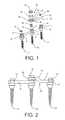
- FIG. 1is an exploded view of a spinal fixation construct with a linking element for adding an additional level of fixation.
- FIG. 2is a side view of an assembled spinal fixation construct including the linking element shown in FIG. 1 .
- FIG. 3is an exploded detail view of the linking assembly and one of the bone engaging fasteners shown in FIGS. 1 and 2 .
- FIG. 4is a side cross-sectional view of the linking assembly engaged to one of the bone engaging fasteners shown in FIG. 2 .
- FIG. 5is an end cross-sectional view of the linking assembly engaged to one of the bone engaging fasteners shown in FIG. 2 .
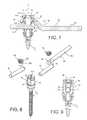
- FIG. 6is an exploded view of a linking element according to a further embodiment for attachment to a bone engaging fastener.
- FIG. 7is a side cross-sectional view of the linking element attached to tithe bone engaging fastener shown in FIG. 8 .
- FIG. 8is an exploded view of a bone engaging fastener with a modified yoke with alternative rod and rod-linking element features.
- FIG. 9is an end cross-sectional view of a rod-linking element feature attached to a bone engaging fastener shown in FIG. 8 .
- FIG. 10is a cross-sectional view of a variable angle bone screw.
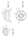
- FIG. 11is a perspective view of a linking element configured for attachment to the bone screw shown in FIG. 10 .
- FIGS. 12-14are perspective, side and bottom views of a locking cap for locking the linking element of FIG. 11 to the bone screw of FIG. 10 .
- FIG. 15is a representation of a spinal fixation construct utilizing the bone engaging fastener, linking element and locking cap shown in FIGS. 10-14 .
- an existing constructincludes a pair of bone-engaging fasteners F 1 and F 2 , and an elongated connecting member R.
- the fastenersmay be pedicle screws and the connecting member a rod as illustrated in the figures, although other forms of these components are contemplated.
- the fasteners F 1 and F 2may be hooks or mono-axial bone screws, but for the present disclosure the fasteners are multi-axial screws configured to be engaged within the pedicles of adjacent vertebrae. Further details of such a multi-axial bone screw are described in co-pending application Ser. No. 11/560,587, filed on Nov. 16, 2006, and published as No. 2008/0119857, which is assigned to the assignee of the present application, the disclosure of which is incorporated herein by reference.
- the bone screwsinclude a yoke 10 with opposite branches 12 forming a slot 13 for receiving the connecting rod R.
- the opposite branchesinclude internal threads 14 for receiving a fastener, such as set screw 36 , that is tightened to lock the connecting member R to the fastener F 1 in a known manner.
- a fastenersuch as set screw 36
- the constructmay extend along multiple spinal levels, include more than two bone screws F 1 and F 2 and incorporate a longer spinal rod R than is depicted in FIG. 1 .
- a linking assembly 20is provided that permits extension of the F 1 -F 2 construct to an additional vertebral level, or more particularly to link to an additional bone screw F 3 .
- the assembly 20includes a linking member 24 that is configured to extend the fixation construct to the additional bone screw F 3 .
- the linking member 24includes an elongated bar 25 that may emulate the connecting member R.
- the connecting memberis a spinal rod
- the bar 25is configured as a rod.
- the connecting memberis a spinal plate
- the bar 25is also configured as a plate.
- the linking member 24further includes a mounting structure connected to the elongated bar that is configured to mount the linking member to the existing fixation construct, or more particularly to the yoke of a bone engaging fastener of the construct.
- the mounting structureincludes a collar 28 that has an inner surface 29 defining an opening 30 therethrough.
- the opening 30is sized so that the collar can be received over the branches 12 of the yoke 10 of one of the bone-engaging fasteners F 2 , thereby permitting the linking member to rotate about the longitudinal axis A of the fastener F 2 .
- the collar 28may bear directly on the connecting rod R disposed within the yoke 10 , which limits the ability of the linking element 24 to pivot about an axis transverse to the longitudinal axis A of the fastener F 2 .
- the collar 28is supported above the rod R, as described below, so that the linking element may pivot through the angle ⁇ shown in FIG. 4 .
- the linking assembly 20further includes a fastener that is configured to engage the yoke to clamp the rod within the yoke.
- the fasteneris an extended set screw 22 that has a lower threaded portion 22 a that is configured to engage the internal threads 14 of the yoke 10 .
- the lower portion 22 a of the set screwdefines a tip 22 b that is configured to engage and restrain the spinal rod R within the yoke.
- the set screwfurther includes an upper portion 22 c that is configured to engage a clamping member, such as nut 34 as described herein.
- the upper portion 22 cdefines a tool recess 22 d for engagement by a driving tool, such as a hex or Torx wrench.
- fastenerssuch as the set screw 36 , are used to fix the rod R within the yoke of each bone screw F 1 and F 2 .
- These set screwsare preferably sized to be completely contained within the confines of the branches 12 .
- the set screwshave a height that is slightly less than the depth of the slot 13 with the rod R therein.
- the extended set screw 22may be sized to extend beyond the upper end of the yoke 10 .
- the extended set screw 22has a height sufficient to pass through the collar 28 and mate with the nut 34 , as shown in FIGS. 4 and 5 .
- the extended set screw 22has a height at least equal to depth of the slot 13 to the rod R therein plus the height of the collar 28 .
- the nut 34may include an internally threaded sleeve 35 that is configured to engage the set screw 22 within the collar.
- the set screw 22has a height so that the upper portion 22 c projects above the collar 28 and engage the nut 34 without the sleeve.
- the upper portion 22 c and nut 34are configured for mutual locking engagement so that the tip 22 b of the set screw 22 exerts a clamping pressure on the rod R when the lower portion 22 a is threaded into the yoke and the upper portion 22 c and nut 34 are engaged with the nut bearing on the collet 32 , as described herein.
- the linking assembly 20is shown in FIG. 2 fastened to the existing construct.
- the bar 25 of the linking element 24is configured to fit within the yoke 10 of an additional bone-engaging fastener F 3 using a conventional set screw 36 .
- the linking element 24may include a bend 26 that allows the third fastener F 3 to be situated at the same prominence as the other fasteners of the existing construct.
- the cavity 29mates with a locking element 32 disposed within the collar 30 .
- the locking elementmay be an expandable element, such as a collet.
- the cavity 29may be spherical to mate with a generally spherical outer surface 32 a of the collet 32 disposed within the opening 30 of the collar 28 .
- the collar 28 and collet 32are configured to fit over the extended set screw 22 so that the set screw can be engaged by the nut 34 .
- the spherical cavity 29 and spherical collet 32form an articulating interface that allows the linking element 24 to achieve different angular orientations relative to the existing construct.
- the linking element 24can pivot upward or downward at an angle ⁇ relative to the existing fasteners. This pivoting can be in combination with rotation about the axis A.
- the provision of this articulating interfaceadds flexibility to the linking assembly 20 to integrate the existing construct with the additional bone fastener.
- the linking assembly 20is engaged to the existing construct by tightening the nut 34 onto the extended set screw 22 so that the nut bears down on the collet 32 .
- the collet 28may be provided with a generally cylindrical interior portion 32 b to receive the generally spherical sleeve 35 of the nut 34 .
- the lower portion 32 c of the colletis tapered and includes expandable slits 33 configured to permit expansion of the effective diameter of the collet.
- the lower portion 32 cfits over a similarly tapered portion 12 a of the yoke arms 12 , as best seen in FIG. 5 .
- the set screw 36 that is engaged to the bone screw of an existing constructmay be readily replaced by the linking element and associated components shown in FIGS. 3-5 . This replacement can occur without disturbing the bone screw F 2 or its engagement with the associated vertebra.
- the rod R of the existing constructmay remain situated within the slot 13 of the yoke 10 .
- the extended set screw 22may be threaded into the yoke 10 and provisionally tightened onto the rod R. Once the compression or distraction is complete, the extended set screw 22 may be finally tightened onto the rod to complete the original construct.
- the additional constructmay then be added using the linking element 24 as described above.
- the collar 28 of the linking element 24may be modified depending upon the configuration of the yoke 10 .
- the branches of the yokeare inwardly deflectable and include upper flanges.
- the cavity 29 of the collar 28may be configured for a snap-fit engagement with these branches.
- the collet 32may be modified to mate with a particular yoke configuration.
- some yoke designsincorporate a tapered upper edge above the internal threads 14 .
- the collet 32may thus include a lower tapered portion that mates within the tapered upper edge of the yoke 10 .
- the spherical surface of the colletstill provides the articulating surface for the spherical cavity 29 of the collar 28 .
- the linking element 24may have a length sufficient to extend across multiple vertebral levels and to link with more than one additional fastener F 3 .
- the linking elementmay also be bendable to allow the element to be contoured to engage fasteners at the additional levels.
- the set screw 36 of an existing constructmay be replaced by a modified set screw 41 to mate with a linking member 45 of a linking assembly 40 , as shown in FIGS. 6 and 7 .
- the set screw 40includes a lower threaded portion 41 a configured to engage the internal threads 14 of the yoke 10 and includes a tip 41 b adapted to engage and restrain the spinal rod R within the yoke.
- the set screw 40further includes a spherically-shaped flange 42 that is configured to reside above the top of the yoke 10 when the lower threaded portion 41 a is fully threaded within the yoke ( FIG. 7 ).
- the flange 42is configured to support a mounting structure of the linking member 45 .
- this mounting structureincludes a collar 47 .
- the collar 47includes a lower spherical surface 48 adapted for articulating contact with the flange 42 so that the linking element 45 may rotate about the axis A and pivot through the angle ⁇ as described above.
- the linking element 45includes an elongated bar 46 that is used to extend the existing construct in the manner described above.
- the bar 46may be similar to the bar 25 in the prior embodiment.
- the modified set screw 40further includes an upper threaded portion 43 that extends through an opening 47 a in the collar of the linking element.
- a jam nut 49is threaded onto the upper portion 43 to clamp the components together.
- the jam nut 49may be provided with a spherical underside to conform to the spherical configuration of the collar 47 of the linking element 45 .
- a bone screw F 2 ′may be provided with a modified yoke 90 , as illustrated in FIGS. 8-9 .
- the yoke 90includes arms 91 that extend upward to a greater height than the arms of the yoke 10 in the prior embodiments. Internal threads 91 a are defined at an upper portion of the arms.
- the rod Ris clamped within the extended yoke by a modified set screw 93 .
- the set screwincludes an upper threaded portion 93 a configured to engage the internal threads 91 a of the yoke. Projecting below the threaded portion is an elongated post 93 b adapted to engage and restrain the rod R when the upper threaded portion 93 a is fully threaded into the yoke.
- the post 93 baccounts for the additional height of the yoke arms 91 between the internal threads 91 a and the rod R seated within the yoke 90 .
- the linking elementincludes a bar 94 a that may be configured like the bars described above.
- the elementincludes a generally spherical knob 95 at one end that is adapted to seat within dimples 92 formed in the inner surface of the arms 91 of the yoke 90 , as shown in FIG. 9 .
- the knob 95includes a generally cylindrical surface 96 contacting the rod R and the set screw 36 threaded into the upper threaded portion of the yoke.
- the cylindrical surfacethus allows the linking element 94 to pivot through the angle ⁇ , but the engagement of the knob 95 within the dimples 92 prevents rotation of the element about the axis of the bone screw.
- the set screw used to lock the linking element and components togethermay be the same as the set screw 36 used in the original construct shown in FIG. 1 .
- a modified bone screw 50is shown in FIG. 10 that includes a head 52 defining an internal spherical cavity 53 .
- a spherical insert 54is disposed within the cavity and engages a mating stem 56 at a threaded engagement 57 .
- a locking sleeve 60is provided that is used to lock the articulating components together when the construct is finalized.
- the bone screw as thus far describedis similar to the bone screw disclosed in the published application No. 2008/0119857 incorporated by reference above.
- the mating stem 56includes an upper stem portion 58 that is adapted to engage a generally planar connecting element, such as a bone plate.
- the upper stem portion 58include threads, such as internal threads 59 , to engage a nut or a bolt to clamp the bone plate to the bone screw 50 .
- the linking element 65includes a support washer 68 that includes a ring 69 defining an opening 70 for receiving the upper stem portion 58 of an existing bone screw therethrough.
- a mounting hub 72 and an alignment hub 73are defined on an upper surface of the ring 69 .
- a pair of attachment beams 75are pivotably mounted to the mounting hub 72 by a hinge pin 76 so that the beams can pivot downward, as shown by the arrow in FIG. 11 , and straddle the alignment hub 73 .
- the attachment beams 75are configured to engage an attachment washer 80 supported on an additional bone screw.
- the attachment washeris configured similar to the washer 68 but without the pivotably mounted beams.
- the washer 80includes a ring 81 with a pair of alignment hubs 82 that are straddled by the attachment beams 75 when they are pivoted forward as shown in FIG. 11 .
- the support washer 68is mounted on the upper stem portion 58 of a bone screw 50 that is engaged within a vertebra.
- the attachment washer 80is mounted on the upper stem portion of the next successive bone screw. Both washers are seated on the locking sleeve 60 ( FIG. 10 ) of the bone screw 50 .
- the attachment beams 75are then pivoted forward onto the attachment washer.
- the beamsmay be fixed in place by the cap 85 shown in FIGS. 12-14 .
- the cap 85includes alignment arms 86 that are complementary with the hubs 72 , 73 on the support washer 68 and the hubs 82 on the attachment washer 80 .
- the arms 86bear against the sides of the attachment beams 75 to trap the beams between the arms of the cap 80 and the hubs.
- the capincludes a set screw 89 extending through a central boss 87 in alignment with the internal threads 59 of the upper stem portion 58 of the bone screw.
- Tightening the set screw 89 into the threads of the upper stem portionnot only fixes the attachment beams 75 to the respective washers, but also tightens the bone screw construct as the spherical insert 54 engages the cavity 53 , the washers 68 , 80 are pressed into the locking sleeve 60 and locking sleeve is pressed into the head 52 of the bone screw.
- the hubs 72 , 73 of the support washer 68 and hubs 82 of the attachment washer 80may define an internal configuration that is adapted to receive an insertion tool.
- the internal configurationmay be, for instance, an undercut that can be engaged by a forceps-type tool to hold the washer and guide it into position over the upper stem portion 58 of a bone screw.
- the cap 85may incorporate an internal hex at the underside of the cap to engage a similarly configured section of the upper stem portion 56 of the bone screw.
- the boss 87may also have a hex configuration to engage a torque wrench.
- the attachment beams 75may include a raised center portion 78 to offset the moment of inertia of the beams.
- the beamsmay also be beveled at their leading edges to facilitate passage of the beams through tissue adjacent the implant site.
- the linking elements disclosed hereinmay be engaged to bone fasteners of an existing construct in situ.
- the linking elementsprovide structure for linking an additional bone fastener or fasteners to the existing construct by removing only one locking element at the end of the construct.
- the connecting element of the existing constructremains undisturbed as the linking elements are added.
Landscapes
- Health & Medical Sciences (AREA)
- Orthopedic Medicine & Surgery (AREA)
- Life Sciences & Earth Sciences (AREA)
- Neurology (AREA)
- Surgery (AREA)
- Heart & Thoracic Surgery (AREA)
- Engineering & Computer Science (AREA)
- Biomedical Technology (AREA)
- Nuclear Medicine, Radiotherapy & Molecular Imaging (AREA)
- Medical Informatics (AREA)
- Molecular Biology (AREA)
- Animal Behavior & Ethology (AREA)
- General Health & Medical Sciences (AREA)
- Public Health (AREA)
- Veterinary Medicine (AREA)
- Surgical Instruments (AREA)
Abstract
Description
Claims (8)
Priority Applications (1)
| Application Number | Priority Date | Filing Date | Title |
|---|---|---|---|
| US12/797,682US8430913B2 (en) | 2009-06-10 | 2010-06-10 | Devices and methods for adding an additional level of fixation to an existing construct |
Applications Claiming Priority (2)
| Application Number | Priority Date | Filing Date | Title |
|---|---|---|---|
| US18571809P | 2009-06-10 | 2009-06-10 | |
| US12/797,682US8430913B2 (en) | 2009-06-10 | 2010-06-10 | Devices and methods for adding an additional level of fixation to an existing construct |
Publications (2)
| Publication Number | Publication Date |
|---|---|
| US20100318131A1 US20100318131A1 (en) | 2010-12-16 |
| US8430913B2true US8430913B2 (en) | 2013-04-30 |
Family
ID=43307075
Family Applications (1)
| Application Number | Title | Priority Date | Filing Date |
|---|---|---|---|
| US12/797,682Expired - Fee RelatedUS8430913B2 (en) | 2009-06-10 | 2010-06-10 | Devices and methods for adding an additional level of fixation to an existing construct |
Country Status (1)
| Country | Link |
|---|---|
| US (1) | US8430913B2 (en) |
Cited By (11)
| Publication number | Priority date | Publication date | Assignee | Title |
|---|---|---|---|---|
| US20130253588A1 (en)* | 2012-03-21 | 2013-09-26 | Wasaw Orthopedic, Inc. | Posterior incremental spinal fixation system |
| US20140052189A1 (en)* | 2012-08-15 | 2014-02-20 | Blackstone Medical, Inc. | Pivoting spinal fixation devices |
| US9700425B1 (en) | 2011-03-20 | 2017-07-11 | Nuvasive, Inc. | Vertebral body replacement and insertion methods |
| US9861495B2 (en) | 2013-03-14 | 2018-01-09 | Raed M. Ali, M.D., Inc. | Lateral interbody fusion devices, systems and methods |
| US9980750B2 (en) | 2011-03-18 | 2018-05-29 | Raed M. Ali, M.D., Inc. | Spinal fusion devices and systems |
| EP3360495A1 (en)* | 2017-02-14 | 2018-08-15 | Warsaw Orthopedic, Inc. | Spinal implant system |
| US10413331B2 (en) | 2016-12-21 | 2019-09-17 | Spine Wave, Inc. | Spinal stabilization system with head to head cross connector |
| US10426521B2 (en)* | 2015-04-24 | 2019-10-01 | Medicrea International | Vertebral osteosynthesis equipment |
| US10687962B2 (en) | 2013-03-14 | 2020-06-23 | Raed M. Ali, M.D., Inc. | Interbody fusion devices, systems and methods |
| US10987228B2 (en) | 2011-03-18 | 2021-04-27 | Raed M. Ali, M.D., Inc. | Devices and methods for transpedicular stabilization of the spine |
| US20240023998A1 (en)* | 2017-02-10 | 2024-01-25 | Medos International Sarl | Tandem rod connectors and related methods |
Families Citing this family (13)
| Publication number | Priority date | Publication date | Assignee | Title |
|---|---|---|---|---|
| US6802844B2 (en)* | 2001-03-26 | 2004-10-12 | Nuvasive, Inc | Spinal alignment apparatus and methods |
| US8100946B2 (en) | 2005-11-21 | 2012-01-24 | Synthes Usa, Llc | Polyaxial bone anchors with increased angulation |
| US9439681B2 (en) | 2007-07-20 | 2016-09-13 | DePuy Synthes Products, Inc. | Polyaxial bone fixation element |
| EP2484300B1 (en)* | 2008-09-05 | 2015-05-20 | Biedermann Technologies GmbH & Co. KG | Stabilization device for bones, in particular for the spinal column |
| JP5815407B2 (en) | 2008-09-12 | 2015-11-17 | ジンテス ゲゼルシャフト ミット ベシュレンクテル ハフツング | Spinal stabilization and guided fixation system |
| KR20110081208A (en) | 2008-09-29 | 2011-07-13 | 신세스 게엠바하 | Multi-Axis Bottom-Loading Screw and Rod Assemblies |
| CA2742399A1 (en) | 2008-11-03 | 2010-06-03 | Dustin M. Harvey | Uni-planar bone fixation assembly |
| KR20120013312A (en) | 2009-04-15 | 2012-02-14 | 신세스 게엠바하 | Orthodontic Connectors for Spinal Structures |
| CA2764841A1 (en)* | 2009-06-17 | 2010-12-23 | Synthes Usa, Llc | Revision connector for spinal constructs |
| US9138264B2 (en)* | 2009-11-02 | 2015-09-22 | Life Spine, Inc. | Laminoplasty rod system |
| US8740950B2 (en) | 2011-12-08 | 2014-06-03 | Spine Wave, Inc. | Methods for percutaneously attaching a cross connector to contralateral spinal constructs |
| US20140277163A1 (en)* | 2013-03-15 | 2014-09-18 | Ryan Kretzer | Reinforcement systems for spine stabilization constructs |
| US10966760B2 (en)* | 2016-10-28 | 2021-04-06 | Warsaw Orthopedic, Inc. | Spinal implant system and method |
Citations (27)
| Publication number | Priority date | Publication date | Assignee | Title |
|---|---|---|---|---|
| DE9402695U1 (en) | 1994-02-18 | 1994-04-14 | Kernforschungszentrum Karlsruhe Gmbh, 76133 Karlsruhe | Implant |
| US5334203A (en) | 1992-09-30 | 1994-08-02 | Amei Technologies Inc. | Spinal fixation system and methods |
| US5569246A (en) | 1993-12-28 | 1996-10-29 | Asahi Kogaku Kogyo Kabushiki Kaisha | Fixing instrument for spinal fusion members |
| US5984923A (en) | 1996-05-09 | 1999-11-16 | Science Et Medecine (Sem) | Anti-shifting system for spinal arthrodesis bar |
| US6077262A (en)* | 1993-06-04 | 2000-06-20 | Synthes (U.S.A.) | Posterior spinal implant |
| US6187005B1 (en) | 1998-09-11 | 2001-02-13 | Synthes (Usa) | Variable angle spinal fixation system |
| US6273914B1 (en) | 1995-09-28 | 2001-08-14 | Sparta, Inc. | Spinal implant |
| US6379354B1 (en) | 1993-10-08 | 2002-04-30 | Chaim Rogozinski | Spinal implant and method |
| US20020143328A1 (en)* | 2001-03-29 | 2002-10-03 | Endius Incorporated | Apparatus for retaining bone portions in a desired spatial relationship |
| US6488682B2 (en) | 2000-03-28 | 2002-12-03 | Showa Ika Kohgyo Co., Ltd. | Spinal implant, driver tool and nut guide |
| US6626904B1 (en) | 1999-07-27 | 2003-09-30 | Societe Etudes Et Developpements - Sed | Implantable intervertebral connection device |
| US6802844B2 (en) | 2001-03-26 | 2004-10-12 | Nuvasive, Inc | Spinal alignment apparatus and methods |
| US20050277923A1 (en)* | 2004-06-09 | 2005-12-15 | Sweeney Patrick J | Spinal fixation system |
| US20060036242A1 (en)* | 2004-08-10 | 2006-02-16 | Nilsson C M | Screw and rod fixation system |
| US20060142758A1 (en) | 2002-09-11 | 2006-06-29 | Dominique Petit | Linking element for dynamically stabilizing a spinal fixing system and spinal fixing system comprising same |
| US20060149244A1 (en)* | 1997-01-22 | 2006-07-06 | Synthes (Usa) | Device for connecting a longitudinal bar to a pedicle screw |
| US20060276794A1 (en) | 2005-05-12 | 2006-12-07 | Stern Joseph D | Revisable anterior cervical plating system |
| US7207992B2 (en) | 2001-09-28 | 2007-04-24 | Stephen Ritland | Connection rod for screw or hook polyaxial system and method of use |
| US20070198014A1 (en)* | 2006-02-07 | 2007-08-23 | Sdgi Holdings, Inc. | Articulating connecting member and anchor systems for spinal stabilization |
| US20070233091A1 (en) | 2006-02-23 | 2007-10-04 | Naifeh Bill R | Multi-level spherical linkage implant system |
| US20070250061A1 (en) | 2006-04-24 | 2007-10-25 | Spinefrontier Lls | Spine fixation method and apparatus |
| US20080183215A1 (en) | 2004-10-20 | 2008-07-31 | Moti Altarac | Multi-level minimally invasive spinal stabilization system |
| US20090177232A1 (en) | 2008-01-03 | 2009-07-09 | Kiester P Douglas | Spine reconstruction rod extender |
| US7645294B2 (en) | 2004-03-31 | 2010-01-12 | Depuy Spine, Inc. | Head-to-head connector spinal fixation system |
| US7695499B2 (en) | 2005-04-29 | 2010-04-13 | Warsaw Orthopedic, Inc. | System, devices and method for augmenting existing fusion constructs |
| US20100256683A1 (en) | 2009-04-01 | 2010-10-07 | Andrew Iott | Orthopedic Clamp and Extension Rod |
| US8021399B2 (en) | 2005-07-19 | 2011-09-20 | Stephen Ritland | Rod extension for extending fusion construct |
- 2010
- 2010-06-10USUS12/797,682patent/US8430913B2/ennot_activeExpired - Fee Related
Patent Citations (27)
| Publication number | Priority date | Publication date | Assignee | Title |
|---|---|---|---|---|
| US5334203A (en) | 1992-09-30 | 1994-08-02 | Amei Technologies Inc. | Spinal fixation system and methods |
| US6077262A (en)* | 1993-06-04 | 2000-06-20 | Synthes (U.S.A.) | Posterior spinal implant |
| US6379354B1 (en) | 1993-10-08 | 2002-04-30 | Chaim Rogozinski | Spinal implant and method |
| US5569246A (en) | 1993-12-28 | 1996-10-29 | Asahi Kogaku Kogyo Kabushiki Kaisha | Fixing instrument for spinal fusion members |
| DE9402695U1 (en) | 1994-02-18 | 1994-04-14 | Kernforschungszentrum Karlsruhe Gmbh, 76133 Karlsruhe | Implant |
| US6273914B1 (en) | 1995-09-28 | 2001-08-14 | Sparta, Inc. | Spinal implant |
| US5984923A (en) | 1996-05-09 | 1999-11-16 | Science Et Medecine (Sem) | Anti-shifting system for spinal arthrodesis bar |
| US20060149244A1 (en)* | 1997-01-22 | 2006-07-06 | Synthes (Usa) | Device for connecting a longitudinal bar to a pedicle screw |
| US6187005B1 (en) | 1998-09-11 | 2001-02-13 | Synthes (Usa) | Variable angle spinal fixation system |
| US6626904B1 (en) | 1999-07-27 | 2003-09-30 | Societe Etudes Et Developpements - Sed | Implantable intervertebral connection device |
| US6488682B2 (en) | 2000-03-28 | 2002-12-03 | Showa Ika Kohgyo Co., Ltd. | Spinal implant, driver tool and nut guide |
| US6802844B2 (en) | 2001-03-26 | 2004-10-12 | Nuvasive, Inc | Spinal alignment apparatus and methods |
| US20020143328A1 (en)* | 2001-03-29 | 2002-10-03 | Endius Incorporated | Apparatus for retaining bone portions in a desired spatial relationship |
| US7207992B2 (en) | 2001-09-28 | 2007-04-24 | Stephen Ritland | Connection rod for screw or hook polyaxial system and method of use |
| US20060142758A1 (en) | 2002-09-11 | 2006-06-29 | Dominique Petit | Linking element for dynamically stabilizing a spinal fixing system and spinal fixing system comprising same |
| US7645294B2 (en) | 2004-03-31 | 2010-01-12 | Depuy Spine, Inc. | Head-to-head connector spinal fixation system |
| US20050277923A1 (en)* | 2004-06-09 | 2005-12-15 | Sweeney Patrick J | Spinal fixation system |
| US20060036242A1 (en)* | 2004-08-10 | 2006-02-16 | Nilsson C M | Screw and rod fixation system |
| US20080183215A1 (en) | 2004-10-20 | 2008-07-31 | Moti Altarac | Multi-level minimally invasive spinal stabilization system |
| US7695499B2 (en) | 2005-04-29 | 2010-04-13 | Warsaw Orthopedic, Inc. | System, devices and method for augmenting existing fusion constructs |
| US20060276794A1 (en) | 2005-05-12 | 2006-12-07 | Stern Joseph D | Revisable anterior cervical plating system |
| US8021399B2 (en) | 2005-07-19 | 2011-09-20 | Stephen Ritland | Rod extension for extending fusion construct |
| US20070198014A1 (en)* | 2006-02-07 | 2007-08-23 | Sdgi Holdings, Inc. | Articulating connecting member and anchor systems for spinal stabilization |
| US20070233091A1 (en) | 2006-02-23 | 2007-10-04 | Naifeh Bill R | Multi-level spherical linkage implant system |
| US20070250061A1 (en) | 2006-04-24 | 2007-10-25 | Spinefrontier Lls | Spine fixation method and apparatus |
| US20090177232A1 (en) | 2008-01-03 | 2009-07-09 | Kiester P Douglas | Spine reconstruction rod extender |
| US20100256683A1 (en) | 2009-04-01 | 2010-10-07 | Andrew Iott | Orthopedic Clamp and Extension Rod |
Cited By (21)
| Publication number | Priority date | Publication date | Assignee | Title |
|---|---|---|---|---|
| US9980750B2 (en) | 2011-03-18 | 2018-05-29 | Raed M. Ali, M.D., Inc. | Spinal fusion devices and systems |
| US10987228B2 (en) | 2011-03-18 | 2021-04-27 | Raed M. Ali, M.D., Inc. | Devices and methods for transpedicular stabilization of the spine |
| US10485672B2 (en) | 2011-03-20 | 2019-11-26 | Nuvasive, Inc. | Vertebral body replacement and insertion methods |
| US9700425B1 (en) | 2011-03-20 | 2017-07-11 | Nuvasive, Inc. | Vertebral body replacement and insertion methods |
| US12186198B2 (en) | 2011-03-20 | 2025-01-07 | Nuvasive, Inc. | Vertebral body replacement and insertion methods |
| US11389301B2 (en) | 2011-03-20 | 2022-07-19 | Nuvasive, Inc. | Vertebral body replacement and insertion methods |
| US8906067B2 (en)* | 2012-03-21 | 2014-12-09 | Warsaw Orthopedic, Inc. | Posterior incremental spinal fixation system |
| US20130253588A1 (en)* | 2012-03-21 | 2013-09-26 | Wasaw Orthopedic, Inc. | Posterior incremental spinal fixation system |
| US20140052189A1 (en)* | 2012-08-15 | 2014-02-20 | Blackstone Medical, Inc. | Pivoting spinal fixation devices |
| US9510866B2 (en)* | 2012-08-15 | 2016-12-06 | Blackstone Medical, Inc. | Pivoting spinal fixation devices |
| US11304824B2 (en) | 2013-03-14 | 2022-04-19 | Raed M. Ali, M.D., Inc. | Interbody fusion devices, systems and methods |
| US10548742B2 (en) | 2013-03-14 | 2020-02-04 | Raed M. Ali, M.D., Inc. | Lateral interbody fusion devices, systems and methods |
| US10687962B2 (en) | 2013-03-14 | 2020-06-23 | Raed M. Ali, M.D., Inc. | Interbody fusion devices, systems and methods |
| US10045857B2 (en) | 2013-03-14 | 2018-08-14 | Raed M. Ali, M.D., Inc. | Lateral interbody fusion devices, systems and methods |
| US11413162B2 (en) | 2013-03-14 | 2022-08-16 | Raed M. Ali, M.D., Inc. | Spinal fusion devices, systems and methods |
| US9861495B2 (en) | 2013-03-14 | 2018-01-09 | Raed M. Ali, M.D., Inc. | Lateral interbody fusion devices, systems and methods |
| US10426521B2 (en)* | 2015-04-24 | 2019-10-01 | Medicrea International | Vertebral osteosynthesis equipment |
| US10413331B2 (en) | 2016-12-21 | 2019-09-17 | Spine Wave, Inc. | Spinal stabilization system with head to head cross connector |
| US11395684B2 (en) | 2016-12-21 | 2022-07-26 | Spine Wave, Inc. | Head to head cross connector |
| US20240023998A1 (en)* | 2017-02-10 | 2024-01-25 | Medos International Sarl | Tandem rod connectors and related methods |
| EP3360495A1 (en)* | 2017-02-14 | 2018-08-15 | Warsaw Orthopedic, Inc. | Spinal implant system |
Also Published As
| Publication number | Publication date |
|---|---|
| US20100318131A1 (en) | 2010-12-16 |
Similar Documents
| Publication | Publication Date | Title |
|---|---|---|
| US8430913B2 (en) | Devices and methods for adding an additional level of fixation to an existing construct | |
| US12303171B2 (en) | Pedicle screw | |
| US7837714B2 (en) | Methods and devices for the interconnection of bone attachment devices | |
| US7914559B2 (en) | Locking device and method employing a posted member to control positioning of a stabilization member of a bone stabilization system | |
| AU2004244781B2 (en) | Connecting device for spinal osteosynthesis | |
| US8870922B2 (en) | Clamp for spinal cross connecting device | |
| US7722648B2 (en) | Crosslink interconnection of bone attachment devices | |
| US7914536B2 (en) | Bone repair device and method | |
| US5415659A (en) | Spinal fixation system and pedicle clamp | |
| US20060052786A1 (en) | Polyaxial device for spine stabilization during osteosynthesis | |
| US20090012567A1 (en) | Locking assembly for securing a rod member in a receiver part for use in spinal or trauma surgery, bone anchoring device with such a locking assembly and tool therefor | |
| US20070055242A1 (en) | Device for securing spinal rods | |
| US20060052783A1 (en) | Polyaxial device for spine stabilization during osteosynthesis | |
| US20060084990A1 (en) | Dual anchor spinal implant apparatus | |
| JP2009509631A (en) | Rod mounting device for head-to-head cross connector | |
| CA2562949A1 (en) | Head-to-head connector spinal fixation system | |
| US20090105755A1 (en) | Apparatus and method for connecting spinal fixation systems together | |
| US20070288003A1 (en) | Locking device and method, for use in a bone stabilization system, employing a break-away interface member rigidly coupled to a seating member | |
| KR200443999Y1 (en) | Multiaxial Spine Fixation Device | |
| RU2335256C2 (en) | Device for treatment of spine fractures | |
| JP2008541861A (en) | Double anchor spinal implant device | |
| RU61543U1 (en) | DEVICE FOR TREATING SPIN FRACTURES | |
| HK1082398A (en) | Instrumentation for stabilizing certain vertebrae of the spine |
Legal Events
| Date | Code | Title | Description |
|---|---|---|---|
| AS | Assignment | Owner name:SPINE WAVE, INC., CONNECTICUT Free format text:ASSIGNMENT OF ASSIGNORS INTEREST;ASSIGNORS:ADAMSON, TIMOTHY E.;JAMES, ANTHONY;MCLEAN, SCOTT;SIGNING DATES FROM 20100615 TO 20100702;REEL/FRAME:024682/0352 | |
| STCF | Information on status: patent grant | Free format text:PATENTED CASE | |
| FPAY | Fee payment | Year of fee payment:4 | |
| AS | Assignment | Owner name:OXFORD FINANCE LLC, VIRGINIA Free format text:SECURITY INTEREST;ASSIGNOR:SPINE WAVE, INC.;REEL/FRAME:046612/0765 Effective date:20180719 Owner name:SILICON VALLEY BANK, MASSACHUSETTS Free format text:SECURITY INTEREST;ASSIGNOR:SPINE WAVE, INC.;REEL/FRAME:046612/0765 Effective date:20180719 | |
| MAFP | Maintenance fee payment | Free format text:PAYMENT OF MAINTENANCE FEE, 8TH YR, SMALL ENTITY (ORIGINAL EVENT CODE: M2552); ENTITY STATUS OF PATENT OWNER: SMALL ENTITY Year of fee payment:8 | |
| AS | Assignment | Owner name:SILICON VALLEY BANK, MASSACHUSETTS Free format text:SECURITY INTEREST;ASSIGNOR:SPINE WAVE, INC.;REEL/FRAME:062886/0507 Effective date:20230228 | |
| FEPP | Fee payment procedure | Free format text:MAINTENANCE FEE REMINDER MAILED (ORIGINAL EVENT CODE: REM.); ENTITY STATUS OF PATENT OWNER: SMALL ENTITY | |
| LAPS | Lapse for failure to pay maintenance fees | Free format text:PATENT EXPIRED FOR FAILURE TO PAY MAINTENANCE FEES (ORIGINAL EVENT CODE: EXP.); ENTITY STATUS OF PATENT OWNER: SMALL ENTITY | |
| STCH | Information on status: patent discontinuation | Free format text:PATENT EXPIRED DUE TO NONPAYMENT OF MAINTENANCE FEES UNDER 37 CFR 1.362 | |
| FP | Lapsed due to failure to pay maintenance fee | Effective date:20250430 |