US8430311B2 - Systems and methods for merchandise automatic checkout - Google Patents
Systems and methods for merchandise automatic checkoutDownload PDFInfo
- Publication number
- US8430311B2 US8430311B2US12/074,263US7426308AUS8430311B2US 8430311 B2US8430311 B2US 8430311B2US 7426308 AUS7426308 AUS 7426308AUS 8430311 B2US8430311 B2US 8430311B2
- Authority
- US
- United States
- Prior art keywords
- subsystem
- visual
- checkout
- image
- data
- Prior art date
- Legal status (The legal status is an assumption and is not a legal conclusion. Google has not performed a legal analysis and makes no representation as to the accuracy of the status listed.)
- Active, expires
Links
Images


Classifications
- G—PHYSICS
- G07—CHECKING-DEVICES
- G07G—REGISTERING THE RECEIPT OF CASH, VALUABLES, OR TOKENS
- G07G1/00—Cash registers
- G07G1/0036—Checkout procedures
- G07G1/0045—Checkout procedures with a code reader for reading of an identifying code of the article to be registered, e.g. barcode reader or radio-frequency identity [RFID] reader
- G07G1/0054—Checkout procedures with a code reader for reading of an identifying code of the article to be registered, e.g. barcode reader or radio-frequency identity [RFID] reader with control of supplementary check-parameters, e.g. weight or number of articles
- A—HUMAN NECESSITIES
- A47—FURNITURE; DOMESTIC ARTICLES OR APPLIANCES; COFFEE MILLS; SPICE MILLS; SUCTION CLEANERS IN GENERAL
- A47F—SPECIAL FURNITURE, FITTINGS, OR ACCESSORIES FOR SHOPS, STOREHOUSES, BARS, RESTAURANTS OR THE LIKE; PAYING COUNTERS
- A47F11/00—Arrangements in shop windows, shop floors or show cases
- A47F11/06—Means for bringing about special optical effects
- A47F11/10—Arrangements of light sources
- A—HUMAN NECESSITIES
- A47—FURNITURE; DOMESTIC ARTICLES OR APPLIANCES; COFFEE MILLS; SPICE MILLS; SUCTION CLEANERS IN GENERAL
- A47F—SPECIAL FURNITURE, FITTINGS, OR ACCESSORIES FOR SHOPS, STOREHOUSES, BARS, RESTAURANTS OR THE LIKE; PAYING COUNTERS
- A47F9/00—Shop, bar, bank or like counters
- A47F9/02—Paying counters
- A47F9/04—Check-out counters, e.g. for self-service stores
- A47F9/046—Arrangement of recording means in or on check-out counters
- A47F9/047—Arrangement of recording means in or on check-out counters for recording self-service articles without cashier or assistant
- A47F9/048—Arrangement of recording means in or on check-out counters for recording self-service articles without cashier or assistant automatically
- G—PHYSICS
- G06—COMPUTING OR CALCULATING; COUNTING
- G06V—IMAGE OR VIDEO RECOGNITION OR UNDERSTANDING
- G06V20/00—Scenes; Scene-specific elements
- G06V20/50—Context or environment of the image
- G06V20/52—Surveillance or monitoring of activities, e.g. for recognising suspicious objects
- G—PHYSICS
- G06—COMPUTING OR CALCULATING; COUNTING
- G06V—IMAGE OR VIDEO RECOGNITION OR UNDERSTANDING
- G06V20/00—Scenes; Scene-specific elements
- G06V20/60—Type of objects
- G06V20/68—Food, e.g. fruit or vegetables
- A—HUMAN NECESSITIES
- A47—FURNITURE; DOMESTIC ARTICLES OR APPLIANCES; COFFEE MILLS; SPICE MILLS; SUCTION CLEANERS IN GENERAL
- A47F—SPECIAL FURNITURE, FITTINGS, OR ACCESSORIES FOR SHOPS, STOREHOUSES, BARS, RESTAURANTS OR THE LIKE; PAYING COUNTERS
- A47F9/00—Shop, bar, bank or like counters
- A47F9/02—Paying counters
- A47F9/04—Check-out counters, e.g. for self-service stores
- A47F2009/041—Accessories for check-out counters, e.g. dividers
Definitions
- the present inventiongenerally relates to object recognition and, more particularly, to systems and method for automatically detecting objects based on pattern recognition and weight measurement.
- the customermay scan the UPC of each item and put the item on a weighing scale. Then, the self-checkout system looks up a database to get the weight data of the item. If the weight data of the item matches the reading of the weighing scale, the item is added to a checkout list.
- these existing self-checkout systemsrely on customers to process the merchandise. Typically, the customers are not as experienced as the cashiers in processing the merchandise, and as a consequence, exiting self-checkout systems may be slower in processing the merchandise than the conventional checkout systems. This can result in lost revenue to the store negating the savings in cashier's labor cost if revenue is dependent upon the checkout speed.
- a self-checkout systemcan yield high throughput and reduce labor and turnover costs if the system can detect and recognize items in the absence of a user needing to physically scan UPCs and/or weigh the items individually.
- a self-checkout systemcan yield high throughput and reduce labor and turnover costs if the system can detect and recognize items in the absence of a user needing to physically scan UPCs and/or weigh the items individually.
- a system for self-checking out an objectincludes: a scale subsystem for measuring a weight of the object; at least one visual sensor for taking at least one image of the object; and a check out subsystem coupled to the at least one visual sensor and the scale subsystem and configured to recognize the object by analyzing the at least one image and the weight.
- a system for checking out an objectincludes: a check out lane; a conveyor subsystem adjacent the lane; at least one visual sensor for taking at least one image of the object on the conveyor subsystem; a scale subsystem for measuring a weight of the object; and a check out subsystem configured to receive the at least one image from the at least one visual sensor and the weight from the scale subsystem and analyze the at least one image and the weight to recognize the object.
- a method of self-checking out an objectincludes steps of: placing the object on a conveyor subsystem; moving the object inside a controlled lighted area via the conveyor subsystem; detecting the object; recognizing the object; measuring a weight of the object in the absence of human intervention; determining if the weight matches the object; and in case of match, adding the object to a checkout list.
- a method of checking out an objectincludes steps of: placing a first separator ahead of the object; placing the object on a conveyor subsystem; placing a second separator behind the object on the conveyor subsystem; starting a transaction upon recognizing the first separator; detecting the object; turning on a lighting subsystem; capturing one or more images of the object; recognizing the object based on the one or more images; recognizing a UPC of the object; measuring the weight of the object; determining if the weight matches the object if UPC is recognized; in case of match, adding the object to a checkout list, in case of no match, sending a notification of an exception, stopping the conveyor subsystem, and resolving the exception; and terminating the transaction upon recognizing the second separator.
- the notification of an exceptioncan be transferred through an Ethernet connection linking a plurality of subsystems or through at least one wireless device linking a plurality of subsystems.
- a method of automating a self-checkout transactionincludes steps of: moving an object on a conveyor subsystem; receiving visual image data of the object from a visual subsystem; analyzing received visual image data to extract one or more visual features; comparing the one or more visual features with feature data stored in an object database to find a set of matches; sending a recognition alert; measuring a weight of the object using a scale subsystem located under the conveyor subsystem; determining if the weight matches the object; if the determination is positive, adding the object to a checkout list; and if the determination is negative, sending a notification of an exception, stopping the conveyor subsystem, and resolving the exception.
- the notification of an exceptioncan be transferred between the subsystems through an Ethernet connection linking a plurality of subsystems or through at least one wireless device linking the subsystems.
- the visual subsystemcaptures visual image data for color and shape recognition, tracking of object and detection of the size of the objects.
- a system for self-checking out an objectincludes: a conveyor subsystem configured to move the object; a housing that encloses a portion of the conveyor subsystem; at least one visual sensor configured to capture at least one image of the object and mounted on the housing; a lighting subsystem that illuminates an area within the housing and is mounted on the housing; a motion trigger subsystem for detecting the object and triggering the lighting subsystem and the at least one visual sensor; and a check out subsystem coupled to the at least one visual sensor and configured to recognize the object by analyzing the at least one image.
- the visual subsystemcaptures visual image data for color and shape recognition, tracking of object and detection of the size of the objects.
- FIG. 1illustrates a system for merchandise automatic checkout in accordance with one embodiment of the present invention
- FIG. 2Aillustrates one embodiment of a recognition system included in the check out system shown in FIG. 1 ;
- FIG. 2Billustrates another embodiment of a recognition system included in the check out system shown in FIG. 1 ;
- FIG. 2Cillustrates yet another embodiment of a recognition system included in the check out system in shown FIG. 1 ;
- FIG. 3illustrates one example of a data structure for a relational database that can be used with the system in FIG. 1 ;
- FIG. 4is a flowchart illustrating the steps that may be carried out by the system in FIG. 1 ;
- FIG. 5is a flowchart illustrating a process to be carried out at the step of automatic processing in FIG. 4 ;
- FIG. 6is a flowchart that illustrates a process to be carried out by the recognition system in FIG. 2 in accordance with one embodiment of the present invention.
- FIG. 7is a flowchart that illustrates a process for training the system in FIG. 1 in accordance with one embodiment of the present invention.
- the present inventionprovides systems and methods through which one or more visual sensors, such as one or more cameras, operatively coupled to a computer system can view, recognize and identify items moving on a conveyor subsystem for automatic check out in the absence of human intervention.
- automatedrefers to the “absence of a user's or human's intervention or efforts, particularly in connection with not having to put an item on a scale or to scan the UPC of an item as in the case of conventional checkout systems.
- the itemsmay be checked out for purchase in a store, and as a further example, the items may be located on a conveyor belt adjacent a checkout lane of a store environment.
- One or more visual sensorscan be placed in a housing that covers a portion of the conveyor belt such that merchandise images may be obtained as the merchandise moves through the housing. Using the images, the merchandise is automatically recognized.
- the present inventionprovides for items to be recognized by analyzing the images and charged in a point-of-sale subsystem.
- a weighing scale(or, equivalently scale subsystem) may be operatively located adjacent the conveyor belt and operated (without human intervention) in tandem with the visual sensor(s) to weigh items sold by weight.
- the reading of the scale subsystem for each recognized itemmay be compared with the weight data of the item stored in a database to determine if the item has been recognized correctly.
- FIG. 1illustrates an embodiment of a self-check out system 100 that may include a checkout lane 102 of a store environment (not to scale) and a checkout counter 104 .
- a point-of-sale (POS) (or, equivalently checkout subsystem) 106such as a cash register, may rest on the checkout counter 104 .
- One or more input devicesmay be coupled to the POS subsystem 106 .
- Exemplary input devicesmay include a barcode scanner, a scale, a keyboard, keypad, touch screen, card reader, and the like.
- the POS subsystem 106may correspond to a checkout terminal used by a checker or cashier.
- the POS subsystem 106may correspond to a self-service checkout terminal.
- the checkout system 100may further include a merchandise conveyor subsystem 110 that may be part of a conveyor belt machine well known in the supermarket industry.
- the conveyor subsystem 110may be used to place merchandise 112 on it by a shopper. So placed, the conveyor subsystem 110 may then move the merchandise 112 in one of the following manners.
- the conveyor belt 110may move continuously.
- the conveyor belt 110may start moving when a conventional motion detector, such as IR detector, detects a customer approaching the checkout lane 102 and sends a signal to the conveyor belt 110 .
- a scale subsystem 122may start the conveyor belt 110 upon detection of any weight on the conveyor belt 110 .
- the location of the scale subsystem 122can be any where along the conveyor belt 110 including but not limited to the beginning of the conveyor belt 110 .
- the scale subsystem 122can be located at the beginning of the conveyor belt 110 to provide an indication that there is merchandise 112 on the conveyor belt 110 waiting to be checked out.
- the scale subsystem 122detects merchandise 112 on the conveyor belt 110 , it will send a signal to start moving the conveyor belt 110 and to begin the automatic checkout process.
- a housing 114may be placed over the conveyor belt 110 and cover a portion of the conveyor belt 110 .
- the housing 114functions as a structure where a motion trigger subsystem 116 , one or more visual cameras 120 , and a lighting subsystem 118 are mounted, it may have any dimension or shape that accommodates the flow of items therethrough.
- the housingmay also include a UPC reader subsystem 113 configured to recognize the UPC of the merchandise 112 contained in the image.
- the UPC reader subsystem 113may be a conventional UPC scanner.
- the UPC recognitionmay be done with a visual sensor.
- a motion trigger subsystem 116may be employed to detect the merchandise 112 moving on the conveyor subsystem 110 and past the motion trigger subsystem 116 .
- the motion trigger subsystem 116may include sensor(s), such as conventional IR detectors.
- the motion trigger subsystem 116may be coupled to a lighting subsystem 118 .
- the motion trigger subsystem 116may trigger the lighting subsystem 118 to light the interior of the housing 114 to provide optimum light illumination when the visual sensors 120 capture visual images.
- the motion trigger subsystem 116may be also coupled to the visual sensors 120 and trigger the visual sensors 120 to obtain images of the merchandise 112 . Triggering of the visual sensors 120 and lighting subsystem 118 may be synchronized such that the lighting subsystem 118 can provide optimum illumination. Alternatively, the motion trigger subsystem 116 can be turned on automatically based on a signal sent by the visual sensor 120 when it detects a motion of merchandise 112 passing through. The automatic checkout process can be initiated when the motion trigger subsystem 116 is turned on. For simplicity, only two visual sensors 120 are shown in FIG. 1 . However, it should be apparent to those of ordinary skill that the present invention may be practiced with any number of visual sensors.
- the visual sensors 120may be used to recognize the presence and identity of the merchandise 112 and provide an indication or instruction to the POS subsystem 106 .
- the visual sensors 120may also determine the size of the merchandise 112 by analyzing the visual images of the merchandise 112 , as described in connection with FIGS. 2 , 3 , 6 and 7 .
- the visual sensors 120may track which merchandise has been recognized and which has not.
- Each of the visual sensors 120may be a digital camera with a CCD imager, a CMOS imager, an infrared imager, and the like.
- the visual sensors 120may include normal lenses or special lenses, such as wide-angle lenses, fish-eye lenses, omni-directional lenses, and the like. Further, the lens may include reflective surfaces, such as planar, parabolic, or conical mirrors, which may be used to provide a relatively large field of view or multiple viewpoints.
- the checkout system 100may further include a scale subsystem 122 , which can be employed to weigh merchandise 112 , for example, when the merchandise is fruit or vegetables.
- the structural incorporation of the scale subsystem 122 with the conveyor belt 110is well known in the art and not detailed for simplicity.
- the system 100may determine the particular fruit or vegetable based on images of its color, texture, and/or shape. So determined, the system 100 may then charge a price of the particular fruit or vegetable based on its weight and price/pound.
- the scale subsystem 122may also be used to check if the merchandise 112 is correctly recognized based on the analysis of images captured by the visual sensor 120 . As will be described in connection with FIGS. 2-3 , the system 100 may use the visual images captured by the visual sensors 120 to recognize the merchandise 112 . Then, the system 100 may look up its object database 302 (shown in FIG. 3 ) to obtain the weight data and/or Universal Product Code (UPC) information of the recognized merchandise 112 . By comparing the reading of the scale subsystem 122 for the recognized merchandise 112 with the weight data and/or UPC information, the system 100 may determine if the merchandise 112 has been correctly recognized.
- object database 302shown in FIG. 3
- UPCUniversal Product Code
- the reading of the scale subsystem 122may not match the weight data and/or UPC information if one or more items are stacked on top of each other on the conveyor subsystem 110 .
- the visual sensors 120may try to recognize the stacked items as a single item and may result a false recognition.
- the merchandise 112may raise an exception as described later.
- one or more special markingssuch as ID number or UPC code, may be introduced onto the merchandise packaging.
- the special markingsmay be printed in ink that is not visible under normal lighting but visible under special lighting, such as UV (or IR) lighting, wherein the lighting subsystem 118 may include a light source for illuminating the special markings.
- the inkmay be an invisible UV fluorescent ink used for conventional security and authentication.
- the special markingsmay be invisible to the naked eye, they can be printed in various sizes and, if needed, cover the entire surface of the package without detracting from the advertisement/eye-appeal of the package design.
- the merchandise 112may be illuminated by the lighting subsystem 118 to reveal the imprinted special markings. Then, the visual sensors 120 may capture visual images including the special markings and analyze the visual images to identify the merchandise 112 , as described in connection with FIGS. 2 , 3 , 6 and 7 .
- a shopping cart 124may occupy the check out lane 102 adjacent the conveyor subsystem 110 .
- the shopping cart 124may include a basket 126 and a lower shelf 128 .
- One or more items 128may be carried on the basket 126 and lower shelf 128 inadvertently or intentionally to defraud the store.
- additional visual sensors 132 a - bmay be located adjacent the check out lane 102 such that the item 130 may be at least partially within the field of view of the visual sensor 132 a - b . More detail on the bottom-of-the-basket prevention is referred to U.S. patent application entitled “Systems and Methods for Merchandise Checkout” filed on Dec. 27, 2004, Ser. No. 11/023,004, which is hereby incorporated herein by reference in its entirety.
- the system 100may start a new transaction upon recognition of a first separator 140 .
- the first separator 140may be, for example, a plastic bar that the system 100 is trained to recognize based on ViPR (visual pattern recognition). Such recognition of a separator bar 140 may be based on a variety of characteristics including but not limited to features, colors, sizes and shapes.
- ViPRvisual pattern recognition
- the customermay place a second separator 142 , wherein the system 100 is also trained to recognize the second separator 142 .
- FIG. 2Aillustrates an embodiment 200 of a recognition system included in the automatic check out system 100 in FIG. 1 .
- the system 200may be implemented in a variety of ways, such as by dedicated hardware, by software executed by a microprocessor, by firmware and/or computer readable medium executed by a microprocessor or by a combination of both dedicated hardware and software.
- only one visual sensor 202 and one checkout subsystem 206are shown in FIG. 2A .
- any number of visual sensors and checkout subsystemsmay be used without deviating from the spirit and scope of the present invention.
- the visual sensor 202may capture images of the items 112 and send visual data 204 to the computer 206 that may process the visual data 204 .
- the visual data 204may include the visual images of the one or more items 112 .
- the visual sensor 202may communicate with the computer 206 via an appropriate interface, such as a direct connection or a networked connection. This interface may be hard wired or wireless. Examples of interface standards that may be used include, but are not limited to, Ethernet, IEEE 802.11, Bluetooth, Universal Serial Bus, FireWire, S-Video, NTSC composite, frame grabber, and the like.
- the computer 206may analyze the visual data 204 provided by the visual sensor 202 and identify visual features of the visual data 204 .
- the featuresmay be identified using an object recognition process that can identify visual features of an image.
- the visual featuresmay correspond to scale-invariant features.
- SIFTscale-invariant feature transformation
- the present inventionteaches an object recognition process that comprises two steps; (1) feature extraction and (2) recognize the object using the extracted features. However, It is not necessary to extract the features to recognize the object.
- the computer 206may be a PC, a server computer, or the like, and may be equipped with a network communication device such as a network interface card, a modem, infra-red (IR) port, or other network connection device suitable for connecting to a network.
- the computer 206may be connected to a network such as a local area network or a wide area network, such that information, including information about merchandise sold by the store, may be accessed from the computer 206 .
- the informationmay be stored on a central computer system, such as a network fileserver, a mainframe, a secure Internet site, and the like.
- the computer 206may execute an appropriate operating system.
- the appropriate operating systemmay include, but is not limited to, operating systems such as Linux, Unix, VxWorks®, QNX® Neutrino®, Microsoft® Windows® 3.1, Microsoft® Windows® 95, Microsoft® Windows® 98, Microsoft® Windows® NT, Microsoft® Windows® 2000, Microsoft® Windows® Me, Microsoft® Windows® XP, Apple® MacOS®, IBM OS/2®, Microsoft® Windows® CE, or Palm OS®.
- the appropriate operating systemmay advantageously include a communications protocol implementation that handles incoming and outgoing message traffic passed over the network.
- the computer 206may be connected to a server 218 that may provide the database information 214 stored in an Object Database 222 and/or a Log Data Storage 224 .
- the server 218may send a query to the computer 206 .
- a queryis an interrogating process initiated by the Supervisor Application 220 residing in the server 218 to acquire Log Data from the computer 206 regarding the status of the computer 206 , transactional information, cashier identification, time stamp of a transaction and the like.
- the computer 206after receiving a query 214 from the server 218 , may retrieve information from the log data 216 to pass on relevant information back to the server 218 , thereby answering the interrogation.
- a Supervisor Application 220 in the server 218may control the flow of information therethrough and manage the Object Database 222 and Log Data Storage 224 .
- the server 218may store all or at least part of the analyzed visual data, such as features descriptors and coordinates associated with the identified features, along with other relevant information in the Object Database 222 .
- the Object Database 222will be discussed in greater detail later in connection with FIG. 3 .
- training imagesmay be captured in a photography studio or on a “workbench,” which can result in higher-quality training images and less physical strain on a human system trainer.
- the computer 206may not need to output match data 208 .
- the features of the training imagesmay be captured and stored in the Object Database 222 .
- the computer 206may compare the visual features with the database information 214 that may include a plurality of known objects stored in the Object Database 222 . If the computer 206 finds a match in the database information 214 , it may return match data 208 to the checkout subsystem 206 . Examples of appropriate match data will be discussed in greater detail later in connection with FIG. 3 .
- the server 218may provide the computer 206 with an updated, or synchronized copy of the Object Database 222 at regular intervals, such as once per hour or once per day, or when an update is requested by the computer 206 or triggered by a human user.
- a signalcan be sent through a wireless device to connect to an operator who may be alerted through a second wireless display device or a monitor that is capable of receiving the signal when the computer 206 cannot find a match.
- the checkout subsystem 212may provide transaction data 210 to the computer 206 . Subsequently, the computer 206 may send log data 216 to the server 218 that may store the data in the Log Data Storage 224 , wherein the log data 216 may include data for one or more transactions. In one embodiment, the computer 206 may store the transaction data 210 locally and provide the server 218 with the stored transaction data for storage in the Log Data Storage 224 at regular intervals, such as once per hour or once per day.
- the server 218 , Object Database 222 and Log Data Storage 224may be connected to a network such as a local area network or a wide area network, such that information, including information from the Object Database 222 and the Log Data Storage 224 , can be accessed remotely.
- the server 208may execute an appropriate operating system.
- the appropriate operating systemmay include but is not limited to operating systems such as Linux, Unix, Microsoft® Windows® 3.1, Microsoft® Windows® 95, Microsoft® Windows® 98, Microsoft® Windows® NT, Microsoft® Windows® 2000, Microsoft® Windows® Me, Microsoft® Windows® XP, Apple® MacOS®, or IBM OS/2®.
- the appropriate operating systemmay advantageously include a communications protocol implementation that handles incoming and outgoing message traffic passed over the network.
- the checkout subsystem 212may take one or more of a wide variety of actions.
- the checkout subsystem 212may provide a visual and/or audible indication that a match has been found for the operator of the checkout subsystem 212 .
- the indicationmay include the name of the object.
- the checkout subsystem 212may automatically add the item or object associated with the identified match to a list or table of items for purchase without any action required from the operator of the checkout subsystem 212 . It will be understood that the list or table may be maintained in the checkout system 212 memory.
- a receipt of the items and their corresponding pricesmay be generated at least partly from the list or table.
- the checkout system 212may also store an electronic log of the item, with a designation that it was sent by the computer 206 .
- the scale subsystem 203may be coupled to the computer 206 and provide a reading to the computer 206 .
- the computer 206may look up the object database 222 to get weight information of the item. Then, the reading of the scale subsystem 203 may be compared with the weight information to check if the item is recognized correctly.
- system 200can include an optional UPC scanner subsystem 207 .
- UPC scanner subsystem 207can be used as a bar code reader of merchandise to corroborate the data capture by other sensors in system 200 or independently used for checkout as in a conventional check out system.
- the UPC code of the itemmay be recognized with a visual sensor and the data capture by the visual sensor may be used to verify correct recognition and weight.
- FIG. 2Billustrates another embodiment 230 of a recognition system included in the self-checkout system in FIG. 1 .
- the system 230may be similar to the system 200 in FIG. 2A with some differences.
- the system 230may optionally include a feature extractor 238 for analyzing visual data 236 sent by a visual sensor 234 to extract features.
- the feature extractor 238may be dedicated hardware.
- the feature extractor 238may also send visual display data 240 to a checkout subsystem 242 that may include a display monitor for displaying the visual display data 240 .
- the computer 206may analyze the visual data 204 to extract features, recognize the items associated with the visual data 204 using the extracted features and send the match data 208 to the checkout subsystem 212 .
- the feature extractor 238may analyze the visual data 236 to extract features and send the analyzed visual data 244 to the server 246 that may subsequently recognize the items.
- the server 246may send the match data 248 to the checkout subsystem 242 .
- the checkout subsystem 212may send transaction log data to the server 218 via the computer 206 while, in the system 230 , the checkout subsystem 242 may send the transaction log data 250 to the server 246 directly.
- both systems 200 and 230may use the same object recognition technique, such as SIFT method, even though different components may perform the process of analysis and recognition.
- the server 246may include a recognition application 245 .
- the scale subsystem 235 and UPC reader subsystem 243may be coupled to the checkout subsystem 242 .
- system 230may operate without the visual display data 240 .
- the visual display data 240may be included in the match data 248 .
- raw visual datacan be sent directly to the server 246 .
- the components of the system 230may communicate with one another via connection mechanisms similar to those of the system 200 .
- the visual sensor 234may communicate with the server 246 via an appropriate interface, such as a direct connection or a networked connection, wherein examples of interface standards may include, but are not limited to, Ethernet, IEEE 802.11, Bluetooth, Universal Serial Bus, FireWire, S-Video, NTSC composite, frame grabber, and the like.
- interface standardsmay include, but are not limited to, Ethernet, IEEE 802.11, Bluetooth, Universal Serial Bus, FireWire, S-Video, NTSC composite, frame grabber, and the like.
- the Object Database 252 and the Log Data Storage 254may be similar to their counterparts of FIG. 2A .
- the server 246may execute an appropriate operating system.
- the appropriate operating systemmay include but is not limited to operating systems such as Linux, Unix, Microsoft® Windows® 3.1, Microsoft® Windows® 95, Microsoft® Windows® 98, Microsoft® Windows® NT, Microsoft® Windows® 2000, Microsoft® Windows® Me, Microsoft® Windows® XP, Apple® MacOS®, or IBM OS/2®.
- the appropriate operating systemmay advantageously include a communications protocol implementation that handles incoming and outgoing message traffic passed over the network.
- the system 230may operate in an operation mode and a training mode.
- the checkout subsystem 242may take actions similar to those performed by the checkout subsystem 212 .
- the checkout subsystem 242may provide transaction log data 250 to the server 246 .
- the server 246may store the data in the Object Database 252 .
- the checkout subsystem 242may store the match data 248 locally and provide the server 246 with the match data for storage in the Object Database 252 at regular intervals, such as once per hour or once per day.
- the checkout system 230may perform a verification to assure that the information based on the weight, visual data and UPC reading matches one another before the checkout system 230 includes merchandise into a transaction.
- the checkout system 230may generate an alert signal to an operator.
- a signalcan be sent through a wireless device to connect to an operator who may be alerted through a second wireless display device or a monitor that is capable of receiving the signal when the computer 206 cannot find a match.
- FIG. 2Cillustrates yet another embodiment of a recognition system included in the automatic checkout system in FIG. 1 .
- the system 260may be similar to the system 230 in FIG. 2B with a difference that the functionality of the feature extractor 238 may be implemented in a checkout subsystem 268 .
- a visual sensor 262may send visual data 264 to a checkout subsystem 268 that may analyze the data to generate analyzed visual data 272 .
- the visual data 264may be provided as an input to a server 274 via the checkout subsystem 268 if the server 274 has the capability to analyze the input and recognize the item associated with the input.
- the server 274may receive the unmodified visual data 264 via the checkout subsystem 268 , and perform the analysis and feature extraction of the unmodified visual data 264 .
- the checkout subsystem 268may use a reading of a scale subsystem 263 to check if the item is recognized correctly in the same manner as described in connection with FIG. 2A .
- the readingmay be input to a server 274 if the server 274 has the capability to check if the item is recognized correctly.
- the checkout subsystem 268may include a UPC reader subsystem 269 .
- a feature extractor 266may be used to extract features and generate analyzed visual data.
- the visual extractor 266may be implemented within a visual sensor unit as shown in FIG. 2B or may be separate from the visual sensor.
- the checkout subsystem 268may simply pass the analyzed visual data 272 to the server 274 .
- the system 260may operate in an operation mode and a training mode.
- the checkout subsystem 268may store a local copy of the Object Database 276 which advantageously may allow the matching process to occur relatively quickly since matching will be performed in the checkout subsystem 268 .
- the log data informationwill be sent to log data storage 278 .
- the server 274may provide the checkout subsystem 268 with an updated, or synchronized copy of the Object Database 276 at regular intervals, such as once per hour or once per day, or when an update is requested by the checkout subsystem 268 .
- the server 274may send the match data 270 to the checkout subsystem 268 . Subsequently, the checkout subsystem 268 may take actions similar to those performed by the checkout subsystem 242 .
- the server 274may also provide the match data to a Log Data Storage 278 . It will be understood that the match data provided to the Log Data Storage 278 can be the same as or can differ from the match data 270 provided to the checkout subsystem 268 .
- the match data provided to the Log Data Storage 278may include an associated timestamp, but the match data 270 provided to the checkout subsystem 268 may not include a timestamp.
- the Log Data Storage 278as well as examples of appropriate match data provided for the Log Data Storage 278 , will be discussed in greater detail later in connection with FIG. 3 .
- the checkout subsystem 268may store match data locally and provide the server 274 with the match data for storage in the Log Data Storage 278 at regular intervals, such as once per hour or once per day.
- the component of the system 260may communicate with one another via connection mechanisms similar to those of the system 230 . Also, it is noted that the Object Database 276 and Log Data Storage 278 may be similar to their counterparts of FIG. 2B and explained in the following sections in connection with FIG. 3 .
- the server 274can reside inside the checkout subsystem 268 using the same processing and memory power in the checkout subsystem 268 to run both the supervisor application 275 and recognition application 273 .
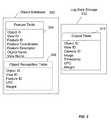
- FIG. 3is a schematic diagram of an Object Database 302 and Log Data Storage 312 (or, equivalently, log data storage database) illustrating an example of a relational database structure in accordance with one embodiment of the present invention.
- a databasemay be implemented on an addressable storage medium and may be implemented using a variety of different types of addressable storage mediums.
- the Object Database 302 and/or the Log Data Storage 312may be entirely contained in a single device or may be spread over several devices, computers, or servers in a network.
- the Object Database 302 and/or the Log Data Storage 312may be implemented in such devices as memory chips, hard drives, optical drives, and the like.
- each of the databasesmay also be, by way of example, an object-oriented database, a hierarchical database, a lightweight directory access protocol (LDAP) directory, an object-oriented-relational database, and the like.
- the databasesmay conform to any database standard, or may even conform to a non-standard private specification.
- the databases 302 and 312may also be implemented utilizing any number of commercially available database products, such as, by way of example, Oracle® from Oracle Corporation, SQL Server and Access from Microsoft Corporation, Sybase® from Sybase, Incorporated, and the like.
- the databases 302 and 312may utilize a relational database management system (RDBMS).
- RDBMSrelational database management system
- the datamay be stored in the form of tables.
- data within the tablemay be stored within fields, which may be arranged into columns and rows.
- Each fieldmay contain one item of information.
- Each column within a tablemay be identified by its column name one type of information, such as a value for a SIFT feature descriptor.
- column namesmay be illustrated in the tables of FIG. 3 .
- a recordalso known as a tuple, may contain a collection of fields constituting a complete set of information.
- the ordering of rowsmay not matter, as the desired row may be identified by examination of the contents of the fields in at least one of the columns or by a combination of fields.
- a field with a unique identifiersuch as an integer, may be used to identify a related collection of fields conveniently.
- two tables 304 and 306may be included in the Object Database 302 , and one table 314 may be included in the Log Data Storage 312 .
- the exemplary data structures represented by the five tables in FIG. 3illustrate a convenient way to maintain data such that an embodiment using the data structures can efficiently store and retrieve the data therein.
- the tables for the Object Database 302may include a Feature Table 304 , and an optional Object Recognition Table 306 .
- the Feature Table 304may store data relating to the identification of an object and a view.
- a viewcan be characterized by a plurality of features.
- the Feature Table 304may include fields for an Object ID, a View ID, a Feature ID for each feature stored, a Feature Coordinates for each feature stored, and a Feature Descriptor associated with each feature stored, view name field, an object name field.
- the Object ID field and the View ID fieldmay be used to identify the records that correspond to a particular view of a particular object.
- a view of an objectmay be typically characterized by a plurality of features. Accordingly, the Feature ID field may be used to identify records that correspond to a particular feature of a view.
- the View ID field for a recordmay be used to identify the particular view corresponding to the feature and may be used to identify related records for other features of the view.
- the Object ID field for a recordmay be used to identify the particular object corresponding to the feature and may be used to identify related records for other views of the object and/or other features associated with the object.
- the Feature Descriptor fieldmay be used to store visual information about the feature such that the feature may be readily identified when the visual sensor observes the view or object again.
- the Feature Coordinate fieldmay be used to store the coordinates of the feature. This may provide a reference for calculations that depend at least in part on the spatial relationships between multiple features.
- An Object Name fieldmay be used to store the name of the object and may be used to store the price of the object.
- the Feature Table 304may, optionally, store additional information associated with the object.
- the View Name fieldmay be used to store the name of the view. For example, it may be convenient to construct a view name by appending a spatial designation to the corresponding object name. As an illustration, if an object name is “Cola 24-Pack,” and the object is packaged in the shape of a box, it may be convenient to name the associated views “Cola 24-Pack Top View,” “Cola 24-Pack Bottom View,” “Cola 24-Pack Front View,” “Cola 24-Pack Back View,” “Cola 24-Pack Left View,” and “Cola 24-Pack Right View.”
- the optional Object Recognition Table 306may include the Object ID field (such as a Universal Product Code), the View ID field, Weight field, UPC field, and the Feature ID field.
- the optional Object Recognition Table 306may advantageously be indexed by the Feature Descriptor, which may facilitate the matching of observed images to views and/or objects.
- the illustrated Log Data Storage 312includes an Output Table 314 .
- the Output Table 314may include fields for an Object ID, a View ID, a Camera ID, a Timestamp, UPC, weight, and a Image.
- the systemmay append records to the Output Table 314 as it recognizes objects during operation. This may advantageously provide a system administrator with the ability to track, log, and report the objects recognized by the system.
- the Camera ID field for a recordmay be used to identify the particular visual sensor associated with the record.
- the Image field for a recordmay be used to store the image associated with the record.
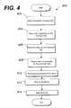
- FIG. 4is a flowchart 400 illustrating the steps that may be carried out by the system 100 in accordance with one embodiment of the present invention. It will be appreciated by those of the ordinary skill that the illustrated steps (or method) may be modified in a variety of ways without departing from the spirit and scope of the system or the method. For example, in another embodiment, various portions of the illustrated method may be combined, be rearranged in an alternate sequence, be removed, and the like. In addition, it should be noted that the method may be performed in a variety of ways, such as by software executing in a general-purpose computer, by firmware executed by a microprocessor, by dedicated hardware, and the like.
- the conveyor subsystem 110(or, conveyor belt) is continuously moving.
- several mechanismsmay start the conveyor subsystem 110 in a state 402 .
- the methodadvances to a state 404 .
- the customermay place a first separator 140 on the belt 110 to initiate a transaction process, where the system 100 is trained to recognize the first separator 140 .
- the system 100may start a new transaction.
- the customermay put one or more items 112 on the belt 110 in a state 406 .
- the customermay put the second separator 142 as an indicator for terminating the transaction.
- the second separator 142may be a plastic bar that the system 100 is trained to recognize.
- a motion detector or IR sensorsmay detect the start of the transaction. Then, the method proceeds to a state 410 .
- the system 100may perform automatic processing of the items 112 , wherein more details of the state 410 will be given later in connection with FIG. 5 .
- the customermay pay for the checked out items and the items may be bagged in states 412 and 414 , respectively.
- the system 110may stop the transaction.
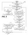
- FIG. 5is a flowchart 500 illustrating a process to be carried out in the operational block 410 in FIG. 4 .
- the automatic processingmay begin in a state 502 .
- the system 100may determine if the first separator 140 has entered into the housing 114 on the moving belt 110 . Recognition of the first separator 140 may be done with ViPR (visual pattern recognition) or with color identification options. If the answer to the state 502 is YES, the method proceeds to a state 504 to start a new transaction for the current customer. Subsequently, the method advances to a state 506 . It should be apparent to those of ordinary skills in the art that detection of a separator 140 to start a transaction is an optional feature of the system 100 . A transaction can also be started by, for example, a customer pressing a start button.
- the system 100may check if it can detect any items 112 on the belt 110 . If any item is detected in the state 506 , the system 100 may optionally turn on the lighting subsystem 118 in a state 508 . Next, in a state 510 , the visual sensors 120 may get image(s) of the item 112 . If the system 110 cannot detect any item in the state 506 , the method proceeds to a state 512 . In the state 512 , the system 100 may determine if it can detect the second separator 142 . Upon affirmative answer to the decision diamond 512 , the system 100 may end the transaction in a state 514 and wait for the first separator of the next customer to start a new transaction.
- the system 100may determine if it can recognize the merchandise 112 in a state 516 . Recognition of the item may be done with ViPR that is explained in connection with FIGS. 2 , 3 and 6 . Alternatively, the color and shape of the item 112 may be used to recognize the item 112 .
- the system 100may determine if it can recognize the UPC, where the UPC may be obtained from the visual image captured in the state 510 or the UPC may be obtained with a conventional UPC scanner. If a UPC is not in the visual image, the system 100 may not take any further steps to recognize the UPC.
- the system 100may use the UPC reader subsystem 113 as a primary recognition tool.
- the system 100may use the visual image to recognize the item 112 if the UPC of the item 112 cannot be recognized.
- the scale subsystem 122may weigh the item 112 . It is noted that the state 520 may also be performed in parallel with the states 516 and 518 . Subsequently, in a state 522 , the system 100 may determine if the merchandise recognized in the state 516 matches the UPC recognized in the state 518 . Also, the reading of the scale subsystem 122 obtained in the state 520 may be used to determine if the recognition in the states 516 and/or 518 is correct. The system 100 may look up the object database 302 (shown in FIG. 3 ) to get the weight data of the merchandise recognized in the state 516 .
- the system 100may check if the merchandise 112 is correctly recognized in the state 516 . Likewise, the system 100 may look up the same database to get the weight data of the merchandise corresponding to the UPC recognized in the state 518 . By comparing the reading of the scale subsystem 122 with the weight data, the system 100 may check if the UPC is correctly recognized in the state 520 . If a match is found, the system 100 may add the item to a checkout list in a state 524 . Otherwise, the method proceeds to a state 526 .
- the system 100may send an exception recognition to stop the conveyor belt 110 . Then, the exception may be processed in a state 528 , where the exception processing may involve a manual intervention or operator notification via a wireless device. Next, the system 100 may check if the exception is resolved in a state 530 . If the answer to the state 530 is positive, the method proceeds to a state 506 .
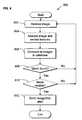
- FIG. 6is a flowchart 600 that illustrates a method to be carried out by the recognition system 200 to recognize objects in accordance with one embodiment of the present invention. It will be appreciated by those of the ordinary skill that the illustrated method may be modified in a variety of ways without departing from the spirit and scope of the present invention. For example, in another embodiment, various portions of the illustrated method may be combined, be rearranged in an alternate sequence, be removed, and the like. In addition, it should be noted that the method may be performed in a variety of ways, such as by software executing in a general-purpose computer, by firmware and/or computer readable medium executed by a microprocessor, by dedicated hardware, and the like.
- the method 600may begin in a state 602 .
- a visual sensorsuch as a camera, may capture one or more images of an object to make visual data.
- a motion trigger subsystemmay trigger the visual sensor and a lighting subsystem upon detection of the object.
- the methodmay advance from the state 602 to an optional state 604 .
- the methodmay analyze the visual data acquired in the state 602 to extract visual features.
- the process of analyzing the visual datamay be performed by a computer 206 , a feature extractor 238 , a checkout system 268 or a server 274 (shown in FIGS. 2A-C ).
- a variety of visual recognition techniquesmay be used, and it will be understood by one of ordinary skill in the art that an appropriate visual recognition technique may depend on a variety of factors, such as the visual sensor used and/or the visual features used.
- the visual featuresmay be identified using an object recognition process that can identify visual features.
- the visual featuresmay correspond to SIFT features.
- the methodmay advance from the state 604 to a state 606 .
- the identified visual featuresmay be compared to visual features stored in a database, such as an Object Database 222 .
- the comparisonmay be done using the SIFT method described earlier.
- the methodmay find one match, may find multiple matches, or may find no matches.
- the method finds multiple matchesit may, based on one or more measures of the quality of the matches, designate one match, such as the match with the highest value of an associated quality measure, as the best match.
- a match confidencemay be associated with a match, wherein the confidence is a variable that is set by adjusting a parameter with a range, such as 0% to 100%, that may relate to, for example, the fraction of the features that are recognized as matching between the visual data and a particular stored image, or stored set of features.
- the parameter with a rangemay also relate to factors including but not limited to re-projection of the feature distance or conditional numbers of affine transform, where these parameters are well known in the art.
- a pre-determined thresholdsuch as a 90% confidence level, the match may not be used.
- the methodfinds multiple matches with match confidence that exceed the pre-determined threshold, the method may return all such matches. The method may advance from the state 606 to a decision block 608 .
- a determinationmay be made as to whether the method found a match in the state 606 . If the method does not identify a match in the state 608 , the method may return to the state 602 to acquire another image. If the method identifies a match in the state 608 , the method may proceed to an optional decision block 610 .
- a determinationmay be made as to whether the match found in the state 606 is considered reliable.
- the system 100may optionally wait for one or more extra cycles to compare the matched object from these extra cycles, so that the system 100 can more reliably determine the true object.
- the system 100may verify that the matched object is identically recognized for two or more cycles before determining a reliable match. Another implementation may compute the statistical probability that each object that can be recognized is present over several cycles.
- a matchmay be considered reliable if the value of the associated quality measure or associated confidence exceeds a predetermined threshold.
- a matchmay be considered reliable if the number of identified features exceeds a predetermined threshold.
- a secondary processsuch as matching against a smaller database, may be used to compare this match to any others present.
- the optional decision block 610may not be used, and the match may always be considered reliable.
- several visual sensorscan be used to increase the reliability of recognition.
- the methodmay return to the state 602 to acquire another image. If the method determines that the match is considered reliable, the method may proceed to a state 612 .
- the methodmay send a recognition alert, where the recognition alert may be followed by one or more actions.
- Exemplary actionmay be displaying item information on a display monitor of a checkout subsystem, adding the item to a shopping list, sending match data to a checkout subsystem, or storing match data into Log Data Storage.
- FIG. 7is a flowchart 700 that illustrates a method for training the system 100 in accordance with one embodiment of the present invention. It will be appreciated by those of ordinary skill that the illustrated method may be modified in a variety of ways without departing from the spirit and scope of the present invention. For example, in another embodiment, various portions of the illustrated method may be combined, be rearranged in an alternate sequence, be removed, and the like. In addition, it should be noted that the method may be performed in a variety of ways, such as by software executing in a general-purpose computer, by firmware and/or computer readable medium executed by a microprocessor, by dedicated hardware, and the like.
- the methodmay begin in a state 702 .
- the methodmay receive visual data of an item from a visual sensor, such as a camera.
- a visual sensorsuch as a camera
- training imagesmay be captured in a photography studio or on a “workbench,” which may result in higher-quality training images and less physical strain on a human system trainer.
- the methodmay advance from the state 702 to a state 704 .
- the systemmay receive electronic data from the manufacturer of the item, where the electronic data may include information associated with the item, such as merchandise specifications, weights, UPC and visual images.
- the methodmay receive data associated with the image received in the state 702 .
- Data associated with an imagemay include, for example, the distance between the visual sensor and the object of the image at the time of image capture, may include an object name, may include a view name, may include an object ID, may include a view ID, may include a unique identifier, may include a text string associated with the object of the image, may include a name of a computer file (such as a sound clip, a movie clip, or other media file) associated with the image, may include a price of the object of the image, may include the UPC associated with the object of the image, and may include a flag indicating that the object of the image is a relatively high security-risk item.
- a computer filesuch as a sound clip, a movie clip, or other media file
- the associated datamay be manually entered, may be automatically generated or retrieved, or a combination of both.
- the operator of the system 100may input all of the associated data manually.
- one or more of the associated data items, such as the object ID or the view IDmay be generated automatically, such as sequentially, by the system.
- one or more of the associated data itemsmay be generated through another input method. For example, a UPC associated with an image may be inputted using a barcode scanner.
- each face of an item that needs to be recognizedshould be captured.
- all such faces of a given objectmay be associated with the same object ID, but associated with different view IDs.
- an item that needs to be recognizedis relatively malleable and/or deformable, such as a bag of pet food or a bag or charcoal briquettes
- several imagesmay be taken at different deformations of the item. It may be beneficial to capture a relatively high-resolution image, such as a close-up, of the most visually distinctive regions of the object, such as the product logo. It may also be beneficial to capture a relatively high-resolution image of the least malleable portions of the item.
- all such deformations and close-ups captured of a given objectmay be associated with the same object ID, but associated with different view IDs.
- the methodmay advance from the state 704 to a state 706 .
- the shapes and colors of the itemsmay be taken at different angles or directions in order to capture a sample of the variety of the items.
- the methodmay store the image received in the state 702 and the associated data collected in the state 704 .
- the system 100may store the image and the associated data in a database, which was described earlier in connection with FIGS. 2A-C .
- the methodmay advance to a decision block 708 .
- the methodmay determine whether or not there are additional images to capture.
- the system 100may ask an operator whether or not there are additional images to capture, and the user's response may determine the action taken by the method.
- the query to the usermay be displayed on a checkout subsystem and the operator may respond via the input devices of the checkout subsystem. If there are additional images to capture, the method may return to the state 702 to receive an additional image. If there are no additional images to capture, the method may proceed to a state 710 .
- the methodmay perform a training subprocess on the captured image or images.
- the methodmay scan the database that contains the images stored in the state 706 , select images that have not been trained, and run the training subroutine on the untrained images.
- the system 100may analyze the image, find the features present in the image and save the features in the Object Database 222 .
- the methodmay advance to an optional state 712 .
- the methodmay delete the images on which the system 100 was trained in the state 710 .
- the matching method described earlier in connection with FIG. 6may use the features associated with a trained image and may not use the actual trained image.
- deleting the trained imagesmay reduce the amount of disk space or memory required to store the Object Database. Then, the method may end and be repeated as desired.
- the system 100may be trained prior to its initial use, and additional training may be performed repeatedly. It will be understood that the number of training images acquired in different training cycles may vary in a wide range.
- embodiments of the system and methodmay advantageously permit one or more visual sensors, such as one or more cameras, operatively coupled to a computer system to view and recognize items located on a conveyor subsystem of a retail store environment.
- These self-checkout systemsmay advantageously increase the checkout out speed and replace cashiers, and as a consequence, may reduce labor and turnover costs.
Landscapes
- Engineering & Computer Science (AREA)
- Physics & Mathematics (AREA)
- General Physics & Mathematics (AREA)
- Multimedia (AREA)
- Theoretical Computer Science (AREA)
- Cash Registers Or Receiving Machines (AREA)
Abstract
Description
Claims (14)
Priority Applications (1)
| Application Number | Priority Date | Filing Date | Title |
|---|---|---|---|
| US12/074,263US8430311B2 (en) | 2004-02-27 | 2008-02-29 | Systems and methods for merchandise automatic checkout |
Applications Claiming Priority (6)
| Application Number | Priority Date | Filing Date | Title |
|---|---|---|---|
| US54856504P | 2004-02-27 | 2004-02-27 | |
| US62155104P | 2004-10-22 | 2004-10-22 | |
| US11/023,004US7100824B2 (en) | 2004-02-27 | 2004-12-27 | System and methods for merchandise checkout |
| PCT/US2005/006079WO2005084227A2 (en) | 2004-02-27 | 2005-02-28 | Systems and methods for merchandise automatic checkout |
| US10/554,516US7337960B2 (en) | 2004-02-27 | 2005-02-28 | Systems and methods for merchandise automatic checkout |
| US12/074,263US8430311B2 (en) | 2004-02-27 | 2008-02-29 | Systems and methods for merchandise automatic checkout |
Related Parent Applications (2)
| Application Number | Title | Priority Date | Filing Date |
|---|---|---|---|
| US10/554,516ContinuationUS7337960B2 (en) | 2004-02-27 | 2005-02-28 | Systems and methods for merchandise automatic checkout |
| PCT/US2005/006079ContinuationWO2005084227A2 (en) | 2004-02-27 | 2005-02-28 | Systems and methods for merchandise automatic checkout |
Publications (2)
| Publication Number | Publication Date |
|---|---|
| US20090152348A1 US20090152348A1 (en) | 2009-06-18 |
| US8430311B2true US8430311B2 (en) | 2013-04-30 |
Family
ID=37447429
Family Applications (2)
| Application Number | Title | Priority Date | Filing Date |
|---|---|---|---|
| US10/554,516Expired - LifetimeUS7337960B2 (en) | 2004-02-27 | 2005-02-28 | Systems and methods for merchandise automatic checkout |
| US12/074,263Active2026-03-05US8430311B2 (en) | 2004-02-27 | 2008-02-29 | Systems and methods for merchandise automatic checkout |
Family Applications Before (1)
| Application Number | Title | Priority Date | Filing Date |
|---|---|---|---|
| US10/554,516Expired - LifetimeUS7337960B2 (en) | 2004-02-27 | 2005-02-28 | Systems and methods for merchandise automatic checkout |
Country Status (1)
| Country | Link |
|---|---|
| US (2) | US7337960B2 (en) |
Cited By (14)
| Publication number | Priority date | Publication date | Assignee | Title |
|---|---|---|---|---|
| US20100076855A1 (en)* | 2008-09-23 | 2010-03-25 | Ehud Dov Karnin | Point of sale system with item image capture and deferred invoicing capability |
| US20100196696A1 (en)* | 2007-07-11 | 2010-08-05 | Technip France | Method and apparatus for anchoring an elongate subsea structure to a termination and a filler material therefor |
| US20130105272A1 (en)* | 2011-01-11 | 2013-05-02 | Wincor Nixdorf International Gmbh | Transport unit and method of operating same |
| US20130175339A1 (en)* | 2012-01-09 | 2013-07-11 | Michael P. Svetal | Using a mobile device to assist in exception handling in self-checkout and automated data capture systems |
| US20150112825A1 (en)* | 2013-10-23 | 2015-04-23 | Toshiba Tec Kabushiki Kaisha | Checkout terminal |
| US9173508B2 (en) | 2010-07-08 | 2015-11-03 | Itab Scanflow Ab | Checkout counter |
| US20160110701A1 (en)* | 2014-10-15 | 2016-04-21 | Toshiba Global Commerce Solutions Holdings Corporation | Method, product, and system for unmanned vehicles in retail environments |
| US20170176241A1 (en)* | 2015-12-21 | 2017-06-22 | Ncr Corporation | Image guided scale calibration |
| US10055626B2 (en)* | 2016-12-06 | 2018-08-21 | Datalogic Usa, Inc. | Data reading system and method with user feedback for improved exception handling and item modeling |
| US10129507B2 (en) | 2014-07-15 | 2018-11-13 | Toshiba Global Commerce Solutions Holdings Corporation | System and method for self-checkout using product images |
| US10157379B2 (en) | 2014-11-12 | 2018-12-18 | Toshiba Global Commerce Solutions Holdings Corporation | Self checkout with security checks based on categorized items |
| US10417526B2 (en)* | 2016-12-08 | 2019-09-17 | Shenzhen University | Object recognition method and device |
| US10430776B2 (en) | 2014-01-09 | 2019-10-01 | Datalogic Usa, Inc. | System and method for exception handling in self-checkout and automated data capture systems |
| US11308297B2 (en) | 2017-04-27 | 2022-04-19 | Datalogic Usa, Inc. | Self-checkout system with scan gate and exception handling |
Families Citing this family (116)
| Publication number | Priority date | Publication date | Assignee | Title |
|---|---|---|---|---|
| US7328842B2 (en)* | 2001-08-14 | 2008-02-12 | Ikan Technologies Inc. | Networked waste processing apparatus |
| EP1445099A1 (en)* | 2003-02-10 | 2004-08-11 | Kba-Giori S.A. | Sensor |
| US7100824B2 (en)* | 2004-02-27 | 2006-09-05 | Evolution Robotics, Inc. | System and methods for merchandise checkout |
| US7516888B1 (en)* | 2004-06-21 | 2009-04-14 | Stoplift, Inc. | Method and apparatus for auditing transaction activity in retail and other environments using visual recognition |
| US7631808B2 (en)* | 2004-06-21 | 2009-12-15 | Stoplift, Inc. | Method and apparatus for detecting suspicious activity using video analysis |
| US9821344B2 (en) | 2004-12-10 | 2017-11-21 | Ikan Holdings Llc | Systems and methods for scanning information from storage area contents |
| US7325729B2 (en)* | 2004-12-22 | 2008-02-05 | International Business Machines Corporation | Enhanced purchase verification for self checkout system |
| US7780081B1 (en)* | 2005-01-03 | 2010-08-24 | RCL Products, Inc. | System and method for security protection, inventory tracking and automated shopping cart checkout |
| WO2007047832A2 (en)* | 2005-10-18 | 2007-04-26 | Datalogic Scanning, Inc. | Integrated data reader and bottom-of-basket item detector |
| US7334729B2 (en)* | 2006-01-06 | 2008-02-26 | International Business Machines Corporation | Apparatus, system, and method for optical verification of product information |
| US20080071559A1 (en)* | 2006-09-19 | 2008-03-20 | Juha Arrasvuori | Augmented reality assisted shopping |
| US7841522B2 (en)* | 2006-11-28 | 2010-11-30 | International Business Machines Corporation | Apparatus, system, and method for measuring light-weight purchase items |
| US7988045B2 (en)* | 2007-05-31 | 2011-08-02 | International Business Machines Corporation | Portable device-based shopping checkout |
| US8794524B2 (en)* | 2007-05-31 | 2014-08-05 | Toshiba Global Commerce Solutions Holdings Corporation | Smart scanning system |
| US9064161B1 (en) | 2007-06-08 | 2015-06-23 | Datalogic ADC, Inc. | System and method for detecting generic items in image sequence |
| US20090026270A1 (en)* | 2007-07-24 | 2009-01-29 | Connell Ii Jonathan H | Secure checkout system |
| US8544736B2 (en)* | 2007-07-24 | 2013-10-01 | International Business Machines Corporation | Item scanning system |
| US7909248B1 (en)* | 2007-08-17 | 2011-03-22 | Evolution Robotics Retail, Inc. | Self checkout with visual recognition |
| US8068674B2 (en)* | 2007-09-04 | 2011-11-29 | Evolution Robotics Retail, Inc. | UPC substitution fraud prevention |
| US9412124B2 (en)* | 2007-09-23 | 2016-08-09 | Sunrise R&D Holdings, Llc | Multi-item scanning systems and methods of items for purchase in a retail environment |
| US7677451B2 (en)* | 2007-12-20 | 2010-03-16 | International Business Machines Corporation | Reducing incident infrared radiation received by one or more infrared detectors in a self checkout point of sale system |
| DE102008010642B4 (en) | 2008-02-22 | 2023-12-21 | Diebold Nixdorf Systems Gmbh | Goods separator bar with machine-readable marking |
| US8746557B2 (en)* | 2008-02-26 | 2014-06-10 | Toshiba Global Commerce Solutions Holding Corporation | Secure self-checkout |
| US8280763B2 (en)* | 2008-02-26 | 2012-10-02 | Connell Ii Jonathan H | Customer rewarding |
| US8061603B2 (en)* | 2008-03-20 | 2011-11-22 | International Business Machines Corporation | Controlling shopper checkout throughput |
| US7889068B2 (en)* | 2008-03-20 | 2011-02-15 | International Business Machines Corporation | Alarm solution for securing shopping checkout |
| US8229158B2 (en)* | 2008-04-29 | 2012-07-24 | International Business Machines Corporation | Method, system, and program product for determining a state of a shopping receptacle |
| US20090272801A1 (en)* | 2008-04-30 | 2009-11-05 | Connell Ii Jonathan H | Deterring checkout fraud |
| US8448859B2 (en)* | 2008-09-05 | 2013-05-28 | Datalogic ADC, Inc. | System and method for preventing cashier and customer fraud at retail checkout |
| US8704821B2 (en)* | 2008-09-18 | 2014-04-22 | International Business Machines Corporation | System and method for managing virtual world environments based upon existing physical environments |
| US9092951B2 (en)* | 2008-10-01 | 2015-07-28 | Ncr Corporation | Surveillance camera assembly for a checkout system |
| US8571298B2 (en)* | 2008-12-23 | 2013-10-29 | Datalogic ADC, Inc. | Method and apparatus for identifying and tallying objects |
| US8494909B2 (en)* | 2009-02-09 | 2013-07-23 | Datalogic ADC, Inc. | Automatic learning in a merchandise checkout system with visual recognition |
| DE102009013636B4 (en)* | 2009-03-18 | 2018-02-15 | Wincor Nixdorf International Gmbh | Device and method for goods registration |
| US20100283850A1 (en)* | 2009-05-05 | 2010-11-11 | Yangde Li | Supermarket video surveillance system |
| US8352214B2 (en)* | 2009-10-12 | 2013-01-08 | Leonard Ian Burrell | Belt image zero tracking system |
| US8364543B2 (en)* | 2009-12-28 | 2013-01-29 | Ncr Corporation | Weight detection for cashier checkout terminals |
| BR112012022984A2 (en) | 2010-03-12 | 2020-08-25 | Sunrise R&D Holdings, Llc | system and method for product identification. |
| US9132352B1 (en)* | 2010-06-24 | 2015-09-15 | Gregory S. Rabin | Interactive system and method for rendering an object |
| US8488881B2 (en) | 2010-07-27 | 2013-07-16 | International Business Machines Corporation | Object segmentation at a self-checkout |
| US9552657B2 (en)* | 2010-08-27 | 2017-01-24 | Kyocera Corporation | Mobile electronic device and control method of mobile electronic device |
| JP5250002B2 (en)* | 2010-09-01 | 2013-07-31 | 東芝テック株式会社 | Reading apparatus and program |
| US9229956B2 (en)* | 2011-01-10 | 2016-01-05 | Microsoft Technology Licensing, Llc | Image retrieval using discriminative visual features |
| WO2012103139A2 (en)* | 2011-01-24 | 2012-08-02 | Datalogic ADC, Inc. | Systems and methods of capturing security images in an automated data reader |
| EP2668612B1 (en) | 2011-01-24 | 2016-01-20 | Datalogic ADC, Inc. | Tunnel or portal scanner and method of scanning for automated checkout |
| CN103430190B (en)* | 2011-01-24 | 2017-08-15 | 数据逻辑Adc公司 | System and method for providing feedback to a user operating an automated order checkout |
| DE102011014562A1 (en)* | 2011-03-21 | 2012-09-27 | Bizerba Gmbh & Co. Kg | Method for operating picture-recognizing devices, in particular for retail scales |
| EP2718895A4 (en)* | 2011-06-06 | 2014-11-05 | Stoplift Inc | NOTIFICATION SYSTEM AND METHODS FOR USE IN RETAIL ENVIRONMENTS |
| JP5596630B2 (en)* | 2011-06-22 | 2014-09-24 | 東芝テック株式会社 | Product list ticketing device |
| US9367770B2 (en) | 2011-08-30 | 2016-06-14 | Digimarc Corporation | Methods and arrangements for identifying objects |
| US11288472B2 (en) | 2011-08-30 | 2022-03-29 | Digimarc Corporation | Cart-based shopping arrangements employing probabilistic item identification |
| US10474858B2 (en) | 2011-08-30 | 2019-11-12 | Digimarc Corporation | Methods of identifying barcoded items by evaluating multiple identification hypotheses, based on data from sensors including inventory sensors and ceiling-mounted cameras |
| WO2013033442A1 (en) | 2011-08-30 | 2013-03-07 | Digimarc Corporation | Methods and arrangements for identifying objects |
| US9033238B2 (en) | 2011-08-30 | 2015-05-19 | Digimarc Corporation | Methods and arrangements for sensing identification information from objects |
| US9129277B2 (en) | 2011-08-30 | 2015-09-08 | Digimarc Corporation | Methods and arrangements for identifying objects |
| JP5485954B2 (en)* | 2011-09-06 | 2014-05-07 | 東芝テック株式会社 | Store system and program |
| US8590789B2 (en) | 2011-09-14 | 2013-11-26 | Metrologic Instruments, Inc. | Scanner with wake-up mode |
| US8479995B2 (en)* | 2011-09-29 | 2013-07-09 | Ncr Corporation | Hybrid optical code scanner and system |
| US8740085B2 (en) | 2012-02-10 | 2014-06-03 | Honeywell International Inc. | System having imaging assembly for use in output of image data |
| US9424480B2 (en)* | 2012-04-20 | 2016-08-23 | Datalogic ADC, Inc. | Object identification using optical code reading and object recognition |
| US8628014B1 (en)* | 2012-05-15 | 2014-01-14 | John M. Hoffer, Jr. | Light field instruction symbol identifier and method of use |
| US9378397B2 (en)* | 2012-07-18 | 2016-06-28 | Datalogic ADC, Inc. | Portal data reader indicator light control |
| EP2877959B1 (en)* | 2012-07-24 | 2018-04-18 | Datalogic USA, Inc. | Systems and methods of object measurement in an automated data reader |
| US9519810B2 (en) | 2012-07-31 | 2016-12-13 | Datalogic ADC, Inc. | Calibration and self-test in automated data reading systems |
| JP5612645B2 (en)* | 2012-09-06 | 2014-10-22 | 東芝テック株式会社 | Information processing apparatus and program |
| DE102012018754A1 (en) | 2012-09-21 | 2014-03-27 | Weber Maschinenbau Gmbh Breidenbach | Food processing apparatus and method for sequentially scanning food products |
| US10089614B1 (en) | 2013-10-04 | 2018-10-02 | Ecr Software Corporation | System and method for self-checkout, scan portal, and pay station environments |
| US9595029B1 (en) | 2012-10-04 | 2017-03-14 | Ecr Software Corporation | System and method for self-checkout, scan portal, and pay station environments |
| US9224184B2 (en) | 2012-10-21 | 2015-12-29 | Digimarc Corporation | Methods and arrangements for identifying objects |
| US8783438B2 (en) | 2012-11-30 | 2014-07-22 | Heb Grocery Company, L.P. | Diverter arm for retail checkstand and retail checkstands and methods incorporating same |
| US9953359B2 (en) | 2013-01-29 | 2018-04-24 | Wal-Mart Stores, Inc. | Cooperative execution of an electronic shopping list |
| US9633390B2 (en)* | 2013-01-30 | 2017-04-25 | Wal-Mart Stores, Inc. | Completing a purchase transaction at various locations within a retail store |
| US9098871B2 (en) | 2013-01-31 | 2015-08-04 | Wal-Mart Stores, Inc. | Method and system for automatically managing an electronic shopping list |
| US9818150B2 (en)* | 2013-04-05 | 2017-11-14 | Digimarc Corporation | Imagery and annotations |
| US20140351265A1 (en)* | 2013-05-23 | 2014-11-27 | Here Global B.V. | Method and apparatus for managing weight of items for transport |
| US9165173B2 (en)* | 2013-05-29 | 2015-10-20 | Ncr Corporation | Security method using an imaging barcode reader |
| US10192208B1 (en) | 2013-07-08 | 2019-01-29 | Ecr Software Corporation | Systems and methods for an improved self-checkout with loss prevention options |
| WO2015017796A2 (en) | 2013-08-02 | 2015-02-05 | Digimarc Corporation | Learning systems and methods |
| US10650232B2 (en)* | 2013-08-26 | 2020-05-12 | Ncr Corporation | Produce and non-produce verification using hybrid scanner |
| US9268979B2 (en) | 2013-09-09 | 2016-02-23 | Datalogic ADC, Inc. | System and method for aiming and calibrating a data reader |
| US11087318B1 (en) | 2013-09-25 | 2021-08-10 | Ecr Software Corporation | System and method for electronic coupons |
| US9053379B2 (en) | 2013-10-04 | 2015-06-09 | Datalogic ADC, Inc. | Single arch portal scanner and method of scanning |
| US10002271B2 (en) | 2013-11-04 | 2018-06-19 | Datalogic Usa, Inc. | Data reading system and method for multi-view imaging using an adjustable mirror |
| US10210361B1 (en) | 2014-08-25 | 2019-02-19 | Ecr Software Corporation | Systems and methods for checkouts, scan portal, and pay station environments with improved attendant work stations |
| US10769389B2 (en)* | 2014-08-27 | 2020-09-08 | Ncr Corporation | Automatic scanner configuration |
| US9898633B2 (en) | 2015-04-29 | 2018-02-20 | Datalogic IP Tech, S.r.l. | Method and system for determining the position and movement of items using radio frequency data |
| EP3087877B1 (en) | 2015-04-29 | 2021-06-02 | Wincor Nixdorf International GmbH | Checkout system assembly with goods separator detection |
| US10282722B2 (en)* | 2015-05-04 | 2019-05-07 | Yi Sun Huang | Machine learning system, method, and program product for point of sale systems |
| US20170083884A1 (en)* | 2015-09-21 | 2017-03-23 | Rami VILMOSH | System and method for automatic identification of products |
| US10650368B2 (en)* | 2016-01-15 | 2020-05-12 | Ncr Corporation | Pick list optimization method |
| US10733444B2 (en) | 2016-07-12 | 2020-08-04 | Walmart Apollo, Llc | Systems and methods for automated assessment of physical objects |
| US10108872B2 (en) | 2016-07-29 | 2018-10-23 | Conduent Business Services, Llc | Multi-angle product imaging device |
| US20180225826A1 (en)* | 2017-02-06 | 2018-08-09 | Toshiba Tec Kabushiki Kaisha | Article recognition apparatus and article recognition method |
| US10095939B2 (en) | 2017-02-06 | 2018-10-09 | Toshiba Tec Kabushiki Kaisha | Article recognition apparatus and article recognition method |
| JP6903524B2 (en)* | 2017-09-01 | 2021-07-14 | 東芝テック株式会社 | Weighing device |
| EP3483780A1 (en)* | 2017-11-10 | 2019-05-15 | Skidata Ag | Classification and identification systems and methods |
| US10818031B2 (en) | 2017-11-22 | 2020-10-27 | Blynk Technology | Systems and methods of determining a location of a mobile container |
| CN107742383B (en)* | 2017-11-30 | 2020-10-23 | 苏州优函信息科技有限公司 | Automatic settlement system and method based on smooth surface imaging |
| US10958807B1 (en)* | 2018-02-08 | 2021-03-23 | Digimarc Corporation | Methods and arrangements for configuring retail scanning systems |
| US11164197B2 (en)* | 2018-04-13 | 2021-11-02 | Shopper Scientist Llc | Shopping time allocated to product exposure in a shopping environment |
| ES2992334T3 (en)* | 2018-10-17 | 2024-12-11 | Supersmart Ltd | Imaging used to reconcile cart weight discrepancy |
| US11126861B1 (en) | 2018-12-14 | 2021-09-21 | Digimarc Corporation | Ambient inventorying arrangements |
| WO2020129066A1 (en)* | 2018-12-20 | 2020-06-25 | Tracxone Ltd. | System and method for classifier training and retrieval from classifier database for large scale product identification |
| CN109886169B (en)* | 2019-02-01 | 2022-11-22 | 腾讯科技(深圳)有限公司 | Article identification method, device, equipment and storage medium applied to unmanned container |
| WO2020206396A1 (en) | 2019-04-04 | 2020-10-08 | Plus One Robotics, Inc. | Industrial robotics systems and methods for continuous and automated learning |
| WO2020210769A1 (en)* | 2019-04-11 | 2020-10-15 | Plus One Robotics, Inc. | Systems and methods for identifying package properties in an automated industrial robotics system |
| CN112304410A (en)* | 2019-07-31 | 2021-02-02 | 梅特勒-托利多(常州)测量技术有限公司 | Weighing device with object recognition and weighing method |
| US11023938B2 (en)* | 2019-09-25 | 2021-06-01 | Ebay Inc. | Auto posting system |
| RU2716298C1 (en)* | 2019-10-21 | 2020-03-11 | Сергей Васильевич Черненко | Checkout box with virtual automatic shopping divider and method of its control |
| US10607080B1 (en)* | 2019-10-25 | 2020-03-31 | 7-Eleven, Inc. | Feedback and training for a machine learning algorithm configured to determine customer purchases during a shopping session at a physical store |
| DE102020122832A1 (en) | 2020-09-01 | 2022-03-03 | Certus Warensicherungs-Systeme Gmbh | Method for visually monitoring the movement of goods to detect passage of the goods at a monitoring point |
| FR3118816A1 (en)* | 2021-01-11 | 2022-07-15 | daniel GIUDICE | Scan Pay and AI self-check via Smartphone |
| WO2022217327A1 (en)* | 2021-04-15 | 2022-10-20 | Ponfac S/A | Checkout counter with reading, checking, sanitizing and monitoring system for use in supermarkets and the like |
| US12100206B2 (en)* | 2021-10-27 | 2024-09-24 | Ncr Voyix Corporation | Real-time risk tracking |
| US20230306625A1 (en)* | 2022-03-22 | 2023-09-28 | Qboid, Inc. | Object dimensioning system |
| US20240242470A1 (en)* | 2023-01-14 | 2024-07-18 | Radiusai, Inc. | Automatic item recognition from captured images during assisted checkout |
Citations (33)
| Publication number | Priority date | Publication date | Assignee | Title |
|---|---|---|---|---|
| US4676343A (en) | 1984-07-09 | 1987-06-30 | Checkrobot Inc. | Self-service distribution system |
| US4929819A (en) | 1988-12-12 | 1990-05-29 | Ncr Corporation | Method and apparatus for customer performed article scanning in self-service shopping |
| US5115888A (en)* | 1991-02-04 | 1992-05-26 | Howard Schneider | Self-serve checkout system |
| EP0672993A2 (en) | 1994-03-07 | 1995-09-20 | Jeffrey M. Novak | Automated apparatus and method for object recognition |
| EP0689175A2 (en) | 1994-05-30 | 1995-12-27 | Kabushiki Kaisha TEC | Check out system |
| US5495097A (en)* | 1993-09-14 | 1996-02-27 | Symbol Technologies, Inc. | Plurality of scan units with scan stitching |
| US5543607A (en) | 1991-02-16 | 1996-08-06 | Hitachi, Ltd. | Self check-out system and POS system |
| EP0843293A2 (en) | 1996-11-13 | 1998-05-20 | Ncr International Inc. | System and method for obtaining prices for items |
| US5883968A (en)* | 1994-07-05 | 1999-03-16 | Aw Computer Systems, Inc. | System and methods for preventing fraud in retail environments, including the detection of empty and non-empty shopping carts |
| US5967264A (en) | 1998-05-01 | 1999-10-19 | Ncr Corporation | Method of monitoring item shuffling in a post-scan area of a self-service checkout terminal |
| US6047889A (en) | 1995-06-08 | 2000-04-11 | Psc Scanning, Inc. | Fixed commercial and industrial scanning system |
| US6069696A (en) | 1995-06-08 | 2000-05-30 | Psc Scanning, Inc. | Object recognition system and method |
| US6236736B1 (en) | 1997-02-07 | 2001-05-22 | Ncr Corporation | Method and apparatus for detecting movement patterns at a self-service checkout terminal |
| US6332573B1 (en) | 1998-11-10 | 2001-12-25 | Ncr Corporation | Produce data collector and produce recognition system |
| US6363366B1 (en) | 1998-08-31 | 2002-03-26 | David L. Henty | Produce identification and pricing system for checkouts |
| US20020138374A1 (en)* | 1999-08-10 | 2002-09-26 | Jennings Andrew John | Item recognition method and apparatus |
| US20030018897A1 (en) | 2001-07-20 | 2003-01-23 | Psc Scanning, Inc. | Video identification verification system and method for a self-checkout system |
| US20030026588A1 (en) | 2001-05-14 | 2003-02-06 | Elder James H. | Attentive panoramic visual sensor |
| US6550583B1 (en) | 2000-08-21 | 2003-04-22 | Optimal Robotics Corp. | Apparatus for self-serve checkout of large order purchases |
| US6598791B2 (en) | 2001-01-19 | 2003-07-29 | Psc Scanning, Inc. | Self-checkout system and method including item buffer for item security verification |
| US6606579B1 (en)* | 2000-08-16 | 2003-08-12 | Ncr Corporation | Method of combining spectral data with non-spectral data in a produce recognition system |
| US20030184440A1 (en) | 2002-03-28 | 2003-10-02 | Ballantyne William John | Method and apparatus for detecting items on the bottom tray of a cart |
| US6860427B1 (en)* | 1993-11-24 | 2005-03-01 | Metrologic Instruments, Inc. | Automatic optical projection scanner for omni-directional reading of bar code symbols within a confined scanning volume |
| US20050060324A1 (en) | 2002-11-13 | 2005-03-17 | Jerry Johnson | System and method for creation and maintenance of a rich content or content-centric electronic catalog |
| US6915008B2 (en)* | 2001-03-08 | 2005-07-05 | Point Grey Research Inc. | Method and apparatus for multi-nodal, three-dimensional imaging |
| US20050173527A1 (en) | 2004-02-11 | 2005-08-11 | International Business Machines Corporation | Product checkout system with anti-theft device |
| US7044370B2 (en) | 2001-07-02 | 2006-05-16 | Ecr Software Corporation | Checkout system with a flexible security verification system |
| US7100824B2 (en) | 2004-02-27 | 2006-09-05 | Evolution Robotics, Inc. | System and methods for merchandise checkout |
| US20070084918A1 (en) | 2005-10-18 | 2007-04-19 | Psc Scanning, Inc. | Integrated data reader and bottom-of-basket item detector |
| US7246745B2 (en) | 2004-02-27 | 2007-07-24 | Evolution Robotics Retail, Inc. | Method of merchandising for checkout lanes |
| US7325729B2 (en) | 2004-12-22 | 2008-02-05 | International Business Machines Corporation | Enhanced purchase verification for self checkout system |
| US7334729B2 (en) | 2006-01-06 | 2008-02-26 | International Business Machines Corporation | Apparatus, system, and method for optical verification of product information |
| US7477780B2 (en)* | 2001-11-05 | 2009-01-13 | Evryx Technologies, Inc. | Image capture and identification system and process |
Family Cites Families (4)
| Publication number | Priority date | Publication date | Assignee | Title |
|---|---|---|---|---|
| US3639762A (en)* | 1969-02-14 | 1972-02-01 | Burton B Hughes | Marking consumer items by rendering colorless markings permanently colored with radiation exposure |
| US5450926A (en)* | 1995-02-08 | 1995-09-19 | Fraser; William A. | Checkout counter order divider including merchandise to be purchased |
| US6542079B1 (en)* | 2000-02-18 | 2003-04-01 | Robert A. Kahl, Sr. | Infrared detection and alarm system for bottom shelf of shopping cart |
| KR100541449B1 (en)* | 2003-07-23 | 2006-01-11 | 삼성전자주식회사 | Panel inspection device |
- 2005
- 2005-02-28USUS10/554,516patent/US7337960B2/ennot_activeExpired - Lifetime
- 2008
- 2008-02-29USUS12/074,263patent/US8430311B2/enactiveActive
Patent Citations (35)
| Publication number | Priority date | Publication date | Assignee | Title |
|---|---|---|---|---|
| US4676343A (en) | 1984-07-09 | 1987-06-30 | Checkrobot Inc. | Self-service distribution system |
| US4929819A (en) | 1988-12-12 | 1990-05-29 | Ncr Corporation | Method and apparatus for customer performed article scanning in self-service shopping |
| US5115888A (en)* | 1991-02-04 | 1992-05-26 | Howard Schneider | Self-serve checkout system |
| US5543607A (en) | 1991-02-16 | 1996-08-06 | Hitachi, Ltd. | Self check-out system and POS system |
| US5495097A (en)* | 1993-09-14 | 1996-02-27 | Symbol Technologies, Inc. | Plurality of scan units with scan stitching |
| US6860427B1 (en)* | 1993-11-24 | 2005-03-01 | Metrologic Instruments, Inc. | Automatic optical projection scanner for omni-directional reading of bar code symbols within a confined scanning volume |
| EP0672993A2 (en) | 1994-03-07 | 1995-09-20 | Jeffrey M. Novak | Automated apparatus and method for object recognition |
| EP0689175A2 (en) | 1994-05-30 | 1995-12-27 | Kabushiki Kaisha TEC | Check out system |
| US5609223A (en) | 1994-05-30 | 1997-03-11 | Kabushiki Kaisha Tec | Checkout system with automatic registration of articles by bar code or physical feature recognition |
| US5883968A (en)* | 1994-07-05 | 1999-03-16 | Aw Computer Systems, Inc. | System and methods for preventing fraud in retail environments, including the detection of empty and non-empty shopping carts |
| US6069696A (en) | 1995-06-08 | 2000-05-30 | Psc Scanning, Inc. | Object recognition system and method |
| US6047889A (en) | 1995-06-08 | 2000-04-11 | Psc Scanning, Inc. | Fixed commercial and industrial scanning system |
| EP0843293A2 (en) | 1996-11-13 | 1998-05-20 | Ncr International Inc. | System and method for obtaining prices for items |
| US6236736B1 (en) | 1997-02-07 | 2001-05-22 | Ncr Corporation | Method and apparatus for detecting movement patterns at a self-service checkout terminal |
| US5967264A (en) | 1998-05-01 | 1999-10-19 | Ncr Corporation | Method of monitoring item shuffling in a post-scan area of a self-service checkout terminal |
| US6363366B1 (en) | 1998-08-31 | 2002-03-26 | David L. Henty | Produce identification and pricing system for checkouts |
| US6332573B1 (en) | 1998-11-10 | 2001-12-25 | Ncr Corporation | Produce data collector and produce recognition system |
| US20020138374A1 (en)* | 1999-08-10 | 2002-09-26 | Jennings Andrew John | Item recognition method and apparatus |
| US6606579B1 (en)* | 2000-08-16 | 2003-08-12 | Ncr Corporation | Method of combining spectral data with non-spectral data in a produce recognition system |
| US6550583B1 (en) | 2000-08-21 | 2003-04-22 | Optimal Robotics Corp. | Apparatus for self-serve checkout of large order purchases |
| US6598791B2 (en) | 2001-01-19 | 2003-07-29 | Psc Scanning, Inc. | Self-checkout system and method including item buffer for item security verification |
| US6915008B2 (en)* | 2001-03-08 | 2005-07-05 | Point Grey Research Inc. | Method and apparatus for multi-nodal, three-dimensional imaging |
| US20030026588A1 (en) | 2001-05-14 | 2003-02-06 | Elder James H. | Attentive panoramic visual sensor |
| US7044370B2 (en) | 2001-07-02 | 2006-05-16 | Ecr Software Corporation | Checkout system with a flexible security verification system |
| US20030018897A1 (en) | 2001-07-20 | 2003-01-23 | Psc Scanning, Inc. | Video identification verification system and method for a self-checkout system |
| US7477780B2 (en)* | 2001-11-05 | 2009-01-13 | Evryx Technologies, Inc. | Image capture and identification system and process |
| US20030184440A1 (en) | 2002-03-28 | 2003-10-02 | Ballantyne William John | Method and apparatus for detecting items on the bottom tray of a cart |
| US20050060324A1 (en) | 2002-11-13 | 2005-03-17 | Jerry Johnson | System and method for creation and maintenance of a rich content or content-centric electronic catalog |
| US20050173527A1 (en) | 2004-02-11 | 2005-08-11 | International Business Machines Corporation | Product checkout system with anti-theft device |
| US20060283943A1 (en) | 2004-02-27 | 2006-12-21 | Evolution Robotics Retail, Inc. | Systems and methods for merchandise checkout |
| US7246745B2 (en) | 2004-02-27 | 2007-07-24 | Evolution Robotics Retail, Inc. | Method of merchandising for checkout lanes |
| US7100824B2 (en) | 2004-02-27 | 2006-09-05 | Evolution Robotics, Inc. | System and methods for merchandise checkout |
| US7325729B2 (en) | 2004-12-22 | 2008-02-05 | International Business Machines Corporation | Enhanced purchase verification for self checkout system |
| US20070084918A1 (en) | 2005-10-18 | 2007-04-19 | Psc Scanning, Inc. | Integrated data reader and bottom-of-basket item detector |
| US7334729B2 (en) | 2006-01-06 | 2008-02-26 | International Business Machines Corporation | Apparatus, system, and method for optical verification of product information |
Non-Patent Citations (6)
| Title |
|---|
| Goncalves, "Self Checkout With Visual Recognition," U.S. Appl. No. 12/229,069, filed Aug. 18, 2008 (assigned to assignee of the present application). |
| http://www.ftxs.fujitsu.com/fujitsutemp.asp?navid=1020, accessed Feb. 25, 2005, 3 pp. |
| http://www.ftxs.fujitsu.com/fujitsutemp.asp?navid=1021, accessed Feb. 25, 2005, 7 pp. |
| http://www.ftxs.fujitsu.com/fujitsutemp.asp?navid=1022, accessed Feb. 25, 2005, 3 pp. |
| http://www.ftxs.fujitsu.com/fujitsutemp.asp?navid=1023, accessed Feb. 25, 2005, 3 pp. |
| Ostrowski , "Systems and Methods for Merchandise Checkout", U.S. Appl. No. 11/466,371, filed Aug. 22, 2006 (assigned to assignee of the present application). |
Cited By (22)
| Publication number | Priority date | Publication date | Assignee | Title |
|---|---|---|---|---|
| US20100196696A1 (en)* | 2007-07-11 | 2010-08-05 | Technip France | Method and apparatus for anchoring an elongate subsea structure to a termination and a filler material therefor |
| US9212767B2 (en)* | 2007-07-11 | 2015-12-15 | Technip France | Method and apparatus for anchoring an elongate subsea structure to a termination and a filler material therefor |
| US8818875B2 (en)* | 2008-09-23 | 2014-08-26 | Toshiba Global Commerce Solutions Holdings Corporation | Point of sale system with item image capture and deferred invoicing capability |
| US20100076855A1 (en)* | 2008-09-23 | 2010-03-25 | Ehud Dov Karnin | Point of sale system with item image capture and deferred invoicing capability |
| US9173508B2 (en) | 2010-07-08 | 2015-11-03 | Itab Scanflow Ab | Checkout counter |
| US9301626B2 (en) | 2010-07-08 | 2016-04-05 | Itab Scanflow Ab | Checkout counter |
| US8960409B2 (en)* | 2011-01-11 | 2015-02-24 | Wincor Nixdorf International Gmbh | Transport unit and method of operating same |
| US20130105272A1 (en)* | 2011-01-11 | 2013-05-02 | Wincor Nixdorf International Gmbh | Transport unit and method of operating same |
| US9082142B2 (en)* | 2012-01-09 | 2015-07-14 | Datalogic ADC, Inc. | Using a mobile device to assist in exception handling in self-checkout and automated data capture systems |
| US20130175339A1 (en)* | 2012-01-09 | 2013-07-11 | Michael P. Svetal | Using a mobile device to assist in exception handling in self-checkout and automated data capture systems |
| US20150112825A1 (en)* | 2013-10-23 | 2015-04-23 | Toshiba Tec Kabushiki Kaisha | Checkout terminal |
| US10430776B2 (en) | 2014-01-09 | 2019-10-01 | Datalogic Usa, Inc. | System and method for exception handling in self-checkout and automated data capture systems |
| US10129507B2 (en) | 2014-07-15 | 2018-11-13 | Toshiba Global Commerce Solutions Holdings Corporation | System and method for self-checkout using product images |
| US9679327B2 (en) | 2014-10-15 | 2017-06-13 | Toshiba Global Commerce Solutions Holdings Corporation | Visual checkout with center of mass security check |
| US20160110701A1 (en)* | 2014-10-15 | 2016-04-21 | Toshiba Global Commerce Solutions Holdings Corporation | Method, product, and system for unmanned vehicles in retail environments |
| US10810648B2 (en)* | 2014-10-15 | 2020-10-20 | Toshiba Global Commerce Solutions | Method, product, and system for unmanned vehicles in retail environments |
| US10157379B2 (en) | 2014-11-12 | 2018-12-18 | Toshiba Global Commerce Solutions Holdings Corporation | Self checkout with security checks based on categorized items |
| US20170176241A1 (en)* | 2015-12-21 | 2017-06-22 | Ncr Corporation | Image guided scale calibration |
| US10041827B2 (en)* | 2015-12-21 | 2018-08-07 | Ncr Corporation | Image guided scale calibration |
| US10055626B2 (en)* | 2016-12-06 | 2018-08-21 | Datalogic Usa, Inc. | Data reading system and method with user feedback for improved exception handling and item modeling |
| US10417526B2 (en)* | 2016-12-08 | 2019-09-17 | Shenzhen University | Object recognition method and device |
| US11308297B2 (en) | 2017-04-27 | 2022-04-19 | Datalogic Usa, Inc. | Self-checkout system with scan gate and exception handling |
Also Published As
| Publication number | Publication date |
|---|---|
| US20090152348A1 (en) | 2009-06-18 |
| US20060261157A1 (en) | 2006-11-23 |
| US7337960B2 (en) | 2008-03-04 |
Similar Documents
| Publication | Publication Date | Title |
|---|---|---|
| US8430311B2 (en) | Systems and methods for merchandise automatic checkout | |
| US7100824B2 (en) | System and methods for merchandise checkout | |
| US7246745B2 (en) | Method of merchandising for checkout lanes | |
| US7646887B2 (en) | Optical flow for object recognition | |
| US8876001B2 (en) | Methods and apparatus for image recognition in checkout verification | |
| CN108320404B (en) | Commodity identification method and device based on neural network and self-service cash register | |
| US5497314A (en) | Automated apparatus and method for object recognition at checkout counters | |
| CN108269371B (en) | Automatic commodity settlement method and device and self-service cash register | |
| US7118026B2 (en) | Apparatus, method, and system for positively identifying an item | |
| CN208188867U (en) | One kind is for nobody self-service product identification system | |
| US7909248B1 (en) | Self checkout with visual recognition | |
| US9152828B2 (en) | System and method for preventing cashier and customer fraud at retail checkout | |
| US6471125B1 (en) | Method of tracking produce selection data | |
| WO2019152279A1 (en) | Product inventorying using image differences | |
| US20090060259A1 (en) | Upc substitution fraud prevention | |
| US10372998B2 (en) | Object recognition for bottom of basket detection | |
| US20240220999A1 (en) | Item verification systems and methods for retail checkout stands | |
| WO2005084227A2 (en) | Systems and methods for merchandise automatic checkout | |
| CN108764129B (en) | Goods shelf and shopping system | |
| US10720027B2 (en) | Reading device and method | |
| US20220270061A1 (en) | System and method for indicating payment method availability on a smart shopping bin | |
| CN108304898A (en) | Self-help settlement shopping cart | |
| WO2025175267A1 (en) | Two-way product verification by reverse lookup | |
| JP2025137679A (en) | Sales System | |
| CN111524303A (en) | Supermarket self-checkout anti-theft system and anti-theft method thereof |
Legal Events
| Date | Code | Title | Description |
|---|---|---|---|
| AS | Assignment | Owner name:EVOLUTION ROBOTICS, INC., CALIFORNIA Free format text:ASSIGNMENT OF ASSIGNORS INTEREST;ASSIGNORS:OSTROWSKI, JIM;MUNICH, MARIO;WISEMAN, JOHN;SIGNING DATES FROM 20050725 TO 20050726;REEL/FRAME:024867/0964 | |
| AS | Assignment | Owner name:EVOLUTION ROBOTICS RETAIL, INC., CALIFORNIA Free format text:CORRECTIVE ASSIGNMENT TO CORRECT THE ERROR IN THE COPY OF ASSIGNMENT THAT MISTAKENLY OMITTED PAGE 2 (SCHEDULE A-1) AS WAS PREVIOUSLY RECORDED ON REEL 024870 FRAME 0800. ASSIGNOR(S) HEREBY CONFIRMS THE PREVIOUSLY RECORDED ASSIGNMENT. A COMPLETE COPY OF THE ASSIGNMENT WITH THE OMITTED PAGE 2 IS NOW PROVIDED.;ASSIGNOR:EVOLUTION ROBOTICS, INC.;REEL/FRAME:024874/0550 Effective date:20051230 Owner name:EVOLUTION ROBOTICS RETAIL, INC., CALIFORNIA Free format text:ASSIGNMENT OF ASSIGNORS INTEREST;ASSIGNOR:EVOLUTION ROBOTICS, INC.;REEL/FRAME:024870/0080 Effective date:20051230 | |
| AS | Assignment | Owner name:DATALOGIC ADC, INC., OREGON Free format text:CHANGE OF NAME;ASSIGNOR:EVOLUTION ROBOTICS RETAIL, INC.;REEL/FRAME:028928/0766 Effective date:20120531 | |
| STCF | Information on status: patent grant | Free format text:PATENTED CASE | |
| CC | Certificate of correction | ||
| FPAY | Fee payment | Year of fee payment:4 | |
| MAFP | Maintenance fee payment | Free format text:PAYMENT OF MAINTENANCE FEE, 8TH YEAR, LARGE ENTITY (ORIGINAL EVENT CODE: M1552); ENTITY STATUS OF PATENT OWNER: LARGE ENTITY Year of fee payment:8 | |
| MAFP | Maintenance fee payment | Free format text:PAYMENT OF MAINTENANCE FEE, 12TH YEAR, LARGE ENTITY (ORIGINAL EVENT CODE: M1553); ENTITY STATUS OF PATENT OWNER: LARGE ENTITY Year of fee payment:12 |