US8430189B2 - Power add-on device for manual wheelchair - Google Patents
Power add-on device for manual wheelchairDownload PDFInfo
- Publication number
- US8430189B2 US8430189B2US12/788,147US78814710AUS8430189B2US 8430189 B2US8430189 B2US 8430189B2US 78814710 AUS78814710 AUS 78814710AUS 8430189 B2US8430189 B2US 8430189B2
- Authority
- US
- United States
- Prior art keywords
- power add
- engagement mechanism
- manual wheelchair
- power
- add
- Prior art date
- Legal status (The legal status is an assumption and is not a legal conclusion. Google has not performed a legal analysis and makes no representation as to the accuracy of the status listed.)
- Active - Reinstated, expires
Links
Images


Classifications
- A—HUMAN NECESSITIES
- A61—MEDICAL OR VETERINARY SCIENCE; HYGIENE
- A61G—TRANSPORT, PERSONAL CONVEYANCES, OR ACCOMMODATION SPECIALLY ADAPTED FOR PATIENTS OR DISABLED PERSONS; OPERATING TABLES OR CHAIRS; CHAIRS FOR DENTISTRY; FUNERAL DEVICES
- A61G5/00—Chairs or personal conveyances specially adapted for patients or disabled persons, e.g. wheelchairs
- A61G5/04—Chairs or personal conveyances specially adapted for patients or disabled persons, e.g. wheelchairs motor-driven
- A61G5/047—Chairs or personal conveyances specially adapted for patients or disabled persons, e.g. wheelchairs motor-driven by a modular detachable drive system
- A—HUMAN NECESSITIES
- A61—MEDICAL OR VETERINARY SCIENCE; HYGIENE
- A61G—TRANSPORT, PERSONAL CONVEYANCES, OR ACCOMMODATION SPECIALLY ADAPTED FOR PATIENTS OR DISABLED PERSONS; OPERATING TABLES OR CHAIRS; CHAIRS FOR DENTISTRY; FUNERAL DEVICES
- A61G5/00—Chairs or personal conveyances specially adapted for patients or disabled persons, e.g. wheelchairs
- A61G5/10—Parts, details or accessories
- A61G5/1054—Large wheels, e.g. higher than the seat portion
- A—HUMAN NECESSITIES
- A61—MEDICAL OR VETERINARY SCIENCE; HYGIENE
- A61G—TRANSPORT, PERSONAL CONVEYANCES, OR ACCOMMODATION SPECIALLY ADAPTED FOR PATIENTS OR DISABLED PERSONS; OPERATING TABLES OR CHAIRS; CHAIRS FOR DENTISTRY; FUNERAL DEVICES
- A61G5/00—Chairs or personal conveyances specially adapted for patients or disabled persons, e.g. wheelchairs
- A61G5/10—Parts, details or accessories
- A61G5/1089—Anti-tip devices
- A—HUMAN NECESSITIES
- A61—MEDICAL OR VETERINARY SCIENCE; HYGIENE
- A61G—TRANSPORT, PERSONAL CONVEYANCES, OR ACCOMMODATION SPECIALLY ADAPTED FOR PATIENTS OR DISABLED PERSONS; OPERATING TABLES OR CHAIRS; CHAIRS FOR DENTISTRY; FUNERAL DEVICES
- A61G2203/00—General characteristics of devices
- A61G2203/10—General characteristics of devices characterised by specific control means, e.g. for adjustment or steering
- A61G2203/14—Joysticks
- A—HUMAN NECESSITIES
- A61—MEDICAL OR VETERINARY SCIENCE; HYGIENE
- A61G—TRANSPORT, PERSONAL CONVEYANCES, OR ACCOMMODATION SPECIALLY ADAPTED FOR PATIENTS OR DISABLED PERSONS; OPERATING TABLES OR CHAIRS; CHAIRS FOR DENTISTRY; FUNERAL DEVICES
- A61G5/00—Chairs or personal conveyances specially adapted for patients or disabled persons, e.g. wheelchairs
- A61G5/04—Chairs or personal conveyances specially adapted for patients or disabled persons, e.g. wheelchairs motor-driven
- A61G5/041—Chairs or personal conveyances specially adapted for patients or disabled persons, e.g. wheelchairs motor-driven having a specific drive-type
- A61G5/043—Mid wheel drive
Definitions
- the present inventionrelates to an auxiliary power add-on attachment for a manual rigid-framed wheelchair.
- U.S. Pat. No. 5,494,126 to Meekerentitled “Apparatus and Method For Attaching a Motorized Wheel to a Wheelchair” discloses a motorized wheel that can be attached to the front of a wheelchair.
- U.S. Pat. No. 5,496,904 to Zwaanentitled “Wheelchair Power System”, discloses a power system that can be added to a manual wheelchair to convert it to an electric-powered wheelchair.
- a power add-on device for powering a manual wheelchairincludes a motorized component including dual electric motors and a power source electrically coupled to the electric motors, wherein each of the motors is configured to turn a respective one of a set of drive wheels.
- the power add-on deviceincludes a latching mechanism adapted to attach the power add-on device to the camber tube of the manual wheelchair; and a controller, reachable by a person sitting in the manual wheelchair, that controls the latching mechanism, the motors, and a swing arm that allows the rear wheels of the manual wheelchair to be lifted off the ground.
- the power add-on devicefeatures a front anti-tip castor wheel and a back anti-tip castor wheel.
- the front wheelscan be lifted several inches off the ground when encountering obstacles or by the user leaning back.
- a notable design feature of the present inventionis that the latching mechanism is not tightly clamped down on the camber tube; instead, it rather surrounds the camber tube, allowing the camber tube to rotate slightly as the wheelchair tilts to allow the front wheels of the manual wheelchair to be lifted.
- the power add-on devicecan be detached from the manual wheelchair and loaded into the trunk of a car when travelling or may be checked in as baggage when flying.
- the latching mechanismincludes a clamshell latching mechanism.
- the clamshell latching mechanismincludes an upper clamshell portion and a bottom clamshell portion, the upper clamshell portion and the bottom clamshell portion attached by a hinge. When the clamshell latching mechanism is in a closed position, the clamshell latching mechanism surrounds the camber tube of the manual wheelchair.
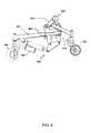
- FIG. 1shows an exemplary power add-on device for a manual wheelchair, in accordance with a preferred embodiment of the present invention
- FIG. 2Ashows a conventional manual wheelchair having a camber tube
- FIG. 2Bshows the power add-on device of FIG. 1 attached to a conventional manual wheelchair
- FIG. 3shows the frame structure of the power add-on device of FIG. 1 ;
- FIGS. 4 to 6show an exemplary power add-on device for a manual wheelchair, in accordance with another preferred embodiment of the present invention
- FIGS. 7 and 8show the frame structure of the power add-on device of FIG. 4 ;
- FIG. 9shows a schematic view of the electrical components for the power add-on device.
- FIG. 1illustrates an exemplary power add-on device 100 useable for powering a manual wheelchair, in accordance with a preferred embodiment of the present invention.
- FIG. 2Billustrates the power add-on device 100 attached to a manual wheelchair 201 having a camber tube 202 .
- the power add-on device 100includes a housing 102 .
- the housing 102includes, therein, two conventional electric wheel-chair motors that are electrically coupled to a power source, and are arranged so that each drives a wheel 104 .
- the manual wheelchair 201can be attached to the power add-on device 100 simply by backing up the manual wheelchair 201 until a pair of latches 103 holds the camber tube of the manual wheelchair 201 .
- no modificationis required to the manual wheelchair 201 .
- the latches 103can be activated by an electric actuator so that when a user wants to de-couple the power add-on device 100 from the manual wheelchair 250 , the user employs remote control 108 to activate the electric actuator so that the latches 103 assume an open position, releasing the manual wheelchair 250 .
- the remote control 108is a conventional joystick or other such user-friendly remote control device.
- the power add-on device 100can also be released manually, for example, by pulling a lever.
- the power add-on device 100has built in recline and anti-tip features so the user can recline and relieve pressure from their seat cushion safely which is very important in order to avoid pressure sores.
- the anti-tip featureis at least in part accomplished by employing front anti-tip castor wheel 107 and rear anti-tip castor wheel 106 .
- the front anti-tip castor wheel 107can be lifted several inches off the ground when encountering obstacles (preferably, as much as three inches).
- a notable design feature of the present inventionis that the latches 103 are not tightly clamped down on the camber tube; instead, the latches 103 rather surround the camber tube, allowing the camber tube to rotate slightly as the manual wheelchair 250 tilts to allow the front wheels of the manual wheelchair to lift of the ground when encountering obstacles or when the user wishes to recline.
- the power add-on device 100includes built-in armrests 109 on which the remote control 108 is mounted which operates the device.
- the armrests 109are mounted to the housing 102 using brackets 111 , as shown.
- the framing structure 400 of the power add-on device 100is shown.
- the framing structure 400includes body frame 401 , motor mount 402 (for securely holding the electric motors), coil-over shock absorber 403 , rear anti-tip castor wheel 106 and front anti-tip castor wheel 107 (to prevent tipping, as discussed above), combination electric actuator 404 and latches 103 (to open the latching system and release the manual wheelchair 201 , as discussed above), armrest mounts 111 (to secure the pair of armrests 109 ), and combination electric actuator 406 /swing arm 408 (to allow the swing arm 408 to pivot upwardly, thereby raising the rear wheels of the manual wheelchair 250 off the ground and transferring the weight of the user from the rear wheels of the manual wheelchair through the shock-absorbed swing arm to provide traction to the power add-on's drive wheels).
- FIG. 4Shows an alternate and preferred latching mechanism wherein the user backs up to an upper clamshell 201 of the latch 203 and then employs the remote control 108 to activate an electric actuator to close the latch 204 by lifting a lower clamshell 204 , thereby securing the camber tube of the manual wheelchair to the power add-on device 100 .
- the upper clamshell 201 and a bottom clamshell 204are attached by at least one hinge.
- the latch 203is in an open position.
- FIG. 5illustrates the latch 203 in a closed position.
- FIG. 6illustrates that the front castor wheel 107 can be lifted off the ground by this mechanism as well to provide extra clearance of obstacles.
- FIG. 7illustrates the framing structure 400 of the power add-on device 100 with the alternate preferred latching mechanism discussed above.
- the electric actuator 404is coupled to a pivot member 405
- the pivot member 405is coupled to the coil-over shock absorber 403 .
- FIG. 8when the electric actuator 404 is activated, the electric actuator 404 applies force to the pivot member 405 , and the pivot member 405 changes the direction of the force to upwardly apply the force to the coil-over shock absorber 403 .
- the coil-over shock absorber 403is coupled to the bottom clamshell 204 , and the coil-over shock absorber 403 pushes the bottom clamshell 204 so as to close the latch 204 .
- FIG. 9shows a schematic view of the electrical components for the power add-on device 100 .
- the electrical systemincludes power source 501 , motors 502 , brakes 503 , linear actuators 504 , 505 , controller 506 , and charger 507 .
- the power source 501comprises energy storage via batteries with charging and current limiting elements.
- the batteriesare electrically connected in series, as shown, and provide all power for all functions. This configuration of battery power allows for use of standard batteries while providing the total output voltage needed for proper operation of the motors 502 , actuators 503 , 504 , and brakes 503 .
- the batteriesare each protected with current limiting elements.
- These current limiting elementscomprise left battery fuse 515 , right battery fuse 516 , and circuit breaker 518 .
- the circuit-opening characteristics of these current limiting elementspreferably are selected based on allowing the circuit breaker first open-circuit followed by the fuses open-circuiting as the total current sourced from the batteries exceed the rated current discharge rate of the batteries.
- the motors 502are preferably direct current motors, sized preferably for propelling the manual wheelchair 201 and an adult user up at least a twenty degree grade.
- the brakesare preferably direct-current-activated at the voltage of the two batteries when connected in series.
- the actuator 504is preferably a direct-current-powered actuator sized and preferably mounted under the frame so as to raise the swing arm 408 , and thus lifting the rear of the manual wheelchair 201 .
- the actuator 505is preferably a direct-current-powered actuator sized and preferably mounted so as to operate the latches 103 , thereby releasing the wheelchair 201 .
- the controller 506preferably includes wired or wireless remote actuator switches attached to a joystick/controller.
- the actuator switchescan be built into the joystick/controller. In either preferred configuration the actuator switches allow the operator to control the raising of the swing arm 408 (thus lifting the rear of the manual wheelchair 201 ), and operating the release lever (opening the latches 103 and releasing the manual chair 201 ), as shown.
Landscapes
- Health & Medical Sciences (AREA)
- Life Sciences & Earth Sciences (AREA)
- Animal Behavior & Ethology (AREA)
- General Health & Medical Sciences (AREA)
- Public Health (AREA)
- Veterinary Medicine (AREA)
- Electric Propulsion And Braking For Vehicles (AREA)
Abstract
Description
Claims (50)
Priority Applications (6)
| Application Number | Priority Date | Filing Date | Title |
|---|---|---|---|
| US12/788,147US8430189B2 (en) | 2009-05-27 | 2010-05-26 | Power add-on device for manual wheelchair |
| EP11787365.3AEP2575720B1 (en) | 2010-05-26 | 2011-05-25 | Power add-on device for manual wheelchair |
| PCT/US2011/037981WO2011150114A1 (en) | 2010-05-26 | 2011-05-25 | Power add-on device for manual wheelchair |
| CA2837282ACA2837282A1 (en) | 2010-05-26 | 2011-05-25 | Power add-on device for manual wheelchair |
| US13/783,175US8960340B2 (en) | 2009-05-27 | 2013-03-01 | Power add-on device for manual wheelchair |
| US14/629,376US9775755B2 (en) | 2009-05-27 | 2015-02-23 | Power add-on device for manual wheelchair |
Applications Claiming Priority (2)
| Application Number | Priority Date | Filing Date | Title |
|---|---|---|---|
| US18160209P | 2009-05-27 | 2009-05-27 | |
| US12/788,147US8430189B2 (en) | 2009-05-27 | 2010-05-26 | Power add-on device for manual wheelchair |
Related Child Applications (1)
| Application Number | Title | Priority Date | Filing Date |
|---|---|---|---|
| US13/783,175Continuation-In-PartUS8960340B2 (en) | 2009-05-27 | 2013-03-01 | Power add-on device for manual wheelchair |
Publications (2)
| Publication Number | Publication Date |
|---|---|
| US20100300777A1 US20100300777A1 (en) | 2010-12-02 |
| US8430189B2true US8430189B2 (en) | 2013-04-30 |
Family
ID=43218953
Family Applications (1)
| Application Number | Title | Priority Date | Filing Date |
|---|---|---|---|
| US12/788,147Active - Reinstated2031-02-16US8430189B2 (en) | 2009-05-27 | 2010-05-26 | Power add-on device for manual wheelchair |
Country Status (4)
| Country | Link |
|---|---|
| US (1) | US8430189B2 (en) |
| EP (1) | EP2575720B1 (en) |
| CA (1) | CA2837282A1 (en) |
| WO (1) | WO2011150114A1 (en) |
Cited By (18)
| Publication number | Priority date | Publication date | Assignee | Title |
|---|---|---|---|---|
| US20120090904A1 (en)* | 2006-07-12 | 2012-04-19 | Bezile Randall J | Wheelchair tow device |
| EP2729108A2 (en) | 2011-07-06 | 2014-05-14 | William Mark Richter | Motion-based power assist system for wheelchairs |
| US20140262575A1 (en)* | 2013-03-14 | 2014-09-18 | Max Mobility, Llc | Motion assistance system for wheelchairs |
| US9775755B2 (en) | 2009-05-27 | 2017-10-03 | Patrick Tallino | Power add-on device for manual wheelchair |
| US9795524B2 (en) | 2015-02-24 | 2017-10-24 | Max Mobility, Llc | Assistive driving system for a wheelchair |
| US10076457B2 (en) | 2016-08-01 | 2018-09-18 | Eric Behm | Propulsion attachment for a manual wheelchair |
| US10106184B2 (en)* | 2015-01-21 | 2018-10-23 | Dane Technologies, Inc. | Cart pusher, mateable carts, and related systems, methods, and devices |
| US10167051B1 (en) | 2017-12-12 | 2019-01-01 | Max Mobility, Llc | Assistive driving system for a wheelchair and method for controlling assistive driving system |
| US10172750B1 (en) | 2015-10-13 | 2019-01-08 | Paul C. Dickie | Power assist apparatus for hand-propelled wheelchairs |
| US10307315B2 (en) | 2017-10-12 | 2019-06-04 | The Center for Discovery, Inc. | Drive assembly for manually powered wheelchair and methods of using the same |
| US10463547B2 (en)* | 2016-02-10 | 2019-11-05 | Toyoda Iron Works Co., Ltd. | Compact electric vehicle |
| US10647342B2 (en) | 2008-05-14 | 2020-05-12 | Dane Technologies, Inc. | Cart pusher, mateable carts, and related systems, methods, and devices |
| US10736799B1 (en) | 2016-10-13 | 2020-08-11 | Paul C. Dickie | Power assist apparatus for hand-propelled wheelchairs |
| US10751232B1 (en)* | 2018-05-18 | 2020-08-25 | Erwin Ilao | Mobile application-controlled undercarriage |
| US10926616B2 (en) | 2016-07-28 | 2021-02-23 | Ford Global Technologies, Llc | Power module for multimodal transportation system |
| US11103394B1 (en) | 2015-10-13 | 2021-08-31 | Paul C. Dickie | Power assist apparatus for hand-propelled wheelchairs |
| US11186342B2 (en)* | 2017-10-27 | 2021-11-30 | Institute Of Technology | Motorized wheel system for pediatric stander |
| US12263707B2 (en) | 2021-04-22 | 2025-04-01 | Steven Baird | Manually propelled floating aquatic wheelchair |
Families Citing this family (11)
| Publication number | Priority date | Publication date | Assignee | Title |
|---|---|---|---|---|
| US20110308880A1 (en)* | 2010-06-17 | 2011-12-22 | Wu's Tech Co., Ltd. | Wheelchair structure |
| US8684113B1 (en) | 2012-02-28 | 2014-04-01 | Gregory Edward Laconis | Attachable, powered drive apparatus for wheelchairs |
| US9050227B1 (en) | 2013-03-15 | 2015-06-09 | Todd Hargroder | Power base attachment |
| ES2572734B1 (en)* | 2015-02-23 | 2017-03-17 | Cástor CASAS TOJO | Off-road wheelchair kit |
| US10130531B1 (en)* | 2015-03-02 | 2018-11-20 | Gregory Edward Laconis | Apparatus for constructing variable configurations of an attachable/detachable motorized drive for standard wheelchairs |
| US9796401B1 (en)* | 2016-11-01 | 2017-10-24 | Michael Ammirati | Motorized wheel accessory for a stroller |
| US10799405B2 (en) | 2018-03-22 | 2020-10-13 | Bolkho, LLC | Wheelchair lift device |
| EP3897500B1 (en)* | 2018-12-21 | 2025-04-16 | Sunrise Medical (US) LLC | Manual wheel chair propulsion system |
| AU2022304739A1 (en) | 2021-06-29 | 2023-12-21 | Game Changer Technologies Inc. | Wheelchair propulsion system |
| ES1285590Y (en)* | 2021-12-23 | 2022-04-20 | Univ Sevilla | AUTONOMOUS DISPLACEMENT PLATFORM |
| FR3132838B1 (en) | 2022-02-18 | 2024-03-01 | B Hive | Motorization device for manual wheelchair |
Citations (22)
| Publication number | Priority date | Publication date | Assignee | Title |
|---|---|---|---|---|
| US4759418A (en) | 1986-02-24 | 1988-07-26 | Goldenfeld Ilia V | Wheelchair drive |
| US5050695A (en) | 1990-07-16 | 1991-09-24 | Kleinwolterink Jr Henry | Power attachment for wheelchair |
| US5113959A (en) | 1989-09-10 | 1992-05-19 | Propel Partnership 1987 | Electric drive attachment for a wheelchair |
| US5125468A (en) | 1989-06-02 | 1992-06-30 | Coker Theodore R | Electric control for wheelchair drive unit |
| US5135063A (en) | 1990-08-30 | 1992-08-04 | Smucker Manufacturing, Inc. | Power unit for driving manually-operated wheelchair |
| US5222567A (en)* | 1991-04-26 | 1993-06-29 | Genus Inc. | Power assist device for a wheelchair |
| US5234066A (en) | 1990-11-13 | 1993-08-10 | Staodyn, Inc. | Power-assisted wheelchair |
| US5350032A (en) | 1993-04-08 | 1994-09-27 | Smith Terry W | Power conversion kit for wheelchair |
| US5351774A (en)* | 1992-06-02 | 1994-10-04 | Quickie Designs Inc. | Powered wheelchair with a detachable power drive assembly |
| US5494126A (en) | 1994-06-02 | 1996-02-27 | Meeker; Galen L. | Apparatus and method for attaching a motorized wheel to a wheelchair |
| US5495904A (en) | 1993-09-14 | 1996-03-05 | Fisher & Paykel Limited | Wheelchair power system |
| US5651422A (en) | 1994-04-22 | 1997-07-29 | The Center For Innovative Technology | Universal-fit, quick-connect power drive/steer attachment for wheelchair |
| US5988304A (en) | 1994-06-22 | 1999-11-23 | Behrendts; Mickey J. | Wheelchair combination |
| US6059060A (en) | 1996-07-01 | 2000-05-09 | Yamaha Hatsudoki Kabushiki Kaisha | Motor-operated wheelchair |
| US20020088657A1 (en) | 2001-01-11 | 2002-07-11 | Vincent Brett | Method and apparatus for motorizing a wheelchair |
| US6481514B2 (en)* | 2000-03-15 | 2002-11-19 | Fuji Jukogyo Kabushiki Kaisha | Auxiliary power device of wheelchair |
| US6766871B2 (en) | 2002-06-27 | 2004-07-27 | George S. Sawyer | Attachment means for attaching a wheelchair to a motorized apparatus |
| US6860347B2 (en) | 2001-11-09 | 2005-03-01 | Daka Research Inc. | Wheelchair drive unit |
| US6896079B1 (en) | 2003-12-17 | 2005-05-24 | Axel Axelsson | Convertible wheelchair and methods for making the same |
| US6935448B2 (en)* | 2000-10-27 | 2005-08-30 | Invacare Corporation | Obstacle traversing wheelchair |
| US7032917B1 (en)* | 2002-09-19 | 2006-04-25 | Eric Mark Chelgren | Rear suspension for wheelchair |
| US7104346B2 (en) | 2003-03-25 | 2006-09-12 | Schaffner Walter E | Power wheelchair |
Family Cites Families (7)
| Publication number | Priority date | Publication date | Assignee | Title |
|---|---|---|---|---|
| US3688857A (en) | 1970-08-17 | 1972-09-05 | Michael J Miller | Self-mounting power unit for wheel chairs |
| JP2896833B2 (en) | 1993-10-06 | 1999-05-31 | 三菱レイヨン株式会社 | Vinyl polymer particles |
| US6616172B1 (en)* | 1999-04-13 | 2003-09-09 | Invacare Corporation | Folding wheelchair with a positioning assembly |
| GB0103280D0 (en)* | 2001-02-12 | 2001-03-28 | Pdq Mobility Ltd | Wheelchair mobility unit |
| CA2487630C (en)* | 2003-11-13 | 2012-08-21 | Orthofab Inc. | Propulsion unit for a wheelchair |
| US7694990B2 (en)* | 2004-11-09 | 2010-04-13 | Invacare Corporation | Anti-tip wheelchair |
| US7886854B2 (en)* | 2008-07-18 | 2011-02-15 | Wu's Tech Co., Ltd. | Wheelchair |
- 2010
- 2010-05-26USUS12/788,147patent/US8430189B2/enactiveActive - Reinstated
- 2011
- 2011-05-25WOPCT/US2011/037981patent/WO2011150114A1/enactiveApplication Filing
- 2011-05-25EPEP11787365.3Apatent/EP2575720B1/ennot_activeNot-in-force
- 2011-05-25CACA2837282Apatent/CA2837282A1/ennot_activeAbandoned
Patent Citations (22)
| Publication number | Priority date | Publication date | Assignee | Title |
|---|---|---|---|---|
| US4759418A (en) | 1986-02-24 | 1988-07-26 | Goldenfeld Ilia V | Wheelchair drive |
| US5125468A (en) | 1989-06-02 | 1992-06-30 | Coker Theodore R | Electric control for wheelchair drive unit |
| US5113959A (en) | 1989-09-10 | 1992-05-19 | Propel Partnership 1987 | Electric drive attachment for a wheelchair |
| US5050695A (en) | 1990-07-16 | 1991-09-24 | Kleinwolterink Jr Henry | Power attachment for wheelchair |
| US5135063A (en) | 1990-08-30 | 1992-08-04 | Smucker Manufacturing, Inc. | Power unit for driving manually-operated wheelchair |
| US5234066A (en) | 1990-11-13 | 1993-08-10 | Staodyn, Inc. | Power-assisted wheelchair |
| US5222567A (en)* | 1991-04-26 | 1993-06-29 | Genus Inc. | Power assist device for a wheelchair |
| US5351774A (en)* | 1992-06-02 | 1994-10-04 | Quickie Designs Inc. | Powered wheelchair with a detachable power drive assembly |
| US5350032A (en) | 1993-04-08 | 1994-09-27 | Smith Terry W | Power conversion kit for wheelchair |
| US5495904A (en) | 1993-09-14 | 1996-03-05 | Fisher & Paykel Limited | Wheelchair power system |
| US5651422A (en) | 1994-04-22 | 1997-07-29 | The Center For Innovative Technology | Universal-fit, quick-connect power drive/steer attachment for wheelchair |
| US5494126A (en) | 1994-06-02 | 1996-02-27 | Meeker; Galen L. | Apparatus and method for attaching a motorized wheel to a wheelchair |
| US5988304A (en) | 1994-06-22 | 1999-11-23 | Behrendts; Mickey J. | Wheelchair combination |
| US6059060A (en) | 1996-07-01 | 2000-05-09 | Yamaha Hatsudoki Kabushiki Kaisha | Motor-operated wheelchair |
| US6481514B2 (en)* | 2000-03-15 | 2002-11-19 | Fuji Jukogyo Kabushiki Kaisha | Auxiliary power device of wheelchair |
| US6935448B2 (en)* | 2000-10-27 | 2005-08-30 | Invacare Corporation | Obstacle traversing wheelchair |
| US20020088657A1 (en) | 2001-01-11 | 2002-07-11 | Vincent Brett | Method and apparatus for motorizing a wheelchair |
| US6860347B2 (en) | 2001-11-09 | 2005-03-01 | Daka Research Inc. | Wheelchair drive unit |
| US6766871B2 (en) | 2002-06-27 | 2004-07-27 | George S. Sawyer | Attachment means for attaching a wheelchair to a motorized apparatus |
| US7032917B1 (en)* | 2002-09-19 | 2006-04-25 | Eric Mark Chelgren | Rear suspension for wheelchair |
| US7104346B2 (en) | 2003-03-25 | 2006-09-12 | Schaffner Walter E | Power wheelchair |
| US6896079B1 (en) | 2003-12-17 | 2005-05-24 | Axel Axelsson | Convertible wheelchair and methods for making the same |
Cited By (32)
| Publication number | Priority date | Publication date | Assignee | Title |
|---|---|---|---|---|
| US8590647B2 (en)* | 2006-07-12 | 2013-11-26 | Randall J. Bezile | Wheelchair tow device |
| US20120090904A1 (en)* | 2006-07-12 | 2012-04-19 | Bezile Randall J | Wheelchair tow device |
| US10647342B2 (en) | 2008-05-14 | 2020-05-12 | Dane Technologies, Inc. | Cart pusher, mateable carts, and related systems, methods, and devices |
| US9775755B2 (en) | 2009-05-27 | 2017-10-03 | Patrick Tallino | Power add-on device for manual wheelchair |
| US11065166B2 (en)* | 2011-07-06 | 2021-07-20 | Max Mobility, Llc | Motion-based power assist system for wheelchairs |
| US20240074924A1 (en)* | 2011-07-06 | 2024-03-07 | Max Mobility, Llc | Motion-based power assist system for wheelchairs |
| EP3260101B1 (en) | 2011-07-06 | 2021-12-08 | Max Mobility, LLC | Motion-based power assist system for wheelchairs |
| US11813209B2 (en)* | 2011-07-06 | 2023-11-14 | Max Mobility, Llc | Motion-based power assist system for wheelchairs |
| US20210338500A1 (en)* | 2011-07-06 | 2021-11-04 | Max Mobility, Llc | Motion-based power assist system for wheelchairs |
| EP2729108A2 (en) | 2011-07-06 | 2014-05-14 | William Mark Richter | Motion-based power assist system for wheelchairs |
| US9144525B2 (en)* | 2013-03-14 | 2015-09-29 | Max Mobility, Llc. | Motion assistance system for wheelchairs |
| US20150351980A1 (en)* | 2013-03-14 | 2015-12-10 | Max Mobility, Llc | Motion assistance system for wheelchairs |
| US10034803B2 (en)* | 2013-03-14 | 2018-07-31 | Max Mobility, Llc | Motion assistance system for wheelchairs |
| US20140262575A1 (en)* | 2013-03-14 | 2014-09-18 | Max Mobility, Llc | Motion assistance system for wheelchairs |
| US10265228B2 (en) | 2013-03-14 | 2019-04-23 | Max Mobility, Llc | Motion assistance system for wheelchairs |
| US9615982B2 (en)* | 2013-03-14 | 2017-04-11 | Max Mobility, Llc. | Motion assistance system for wheelchairs |
| US20170027785A1 (en)* | 2013-03-14 | 2017-02-02 | Max Mobility, Llc | Motion assistance system for wheelchairs |
| US10106184B2 (en)* | 2015-01-21 | 2018-10-23 | Dane Technologies, Inc. | Cart pusher, mateable carts, and related systems, methods, and devices |
| US9795524B2 (en) | 2015-02-24 | 2017-10-24 | Max Mobility, Llc | Assistive driving system for a wheelchair |
| US10322043B2 (en) | 2015-02-24 | 2019-06-18 | Max Mobility, Llc | Assistive driving system for a wheelchair |
| US10172750B1 (en) | 2015-10-13 | 2019-01-08 | Paul C. Dickie | Power assist apparatus for hand-propelled wheelchairs |
| US11103394B1 (en) | 2015-10-13 | 2021-08-31 | Paul C. Dickie | Power assist apparatus for hand-propelled wheelchairs |
| US10463547B2 (en)* | 2016-02-10 | 2019-11-05 | Toyoda Iron Works Co., Ltd. | Compact electric vehicle |
| US10926616B2 (en) | 2016-07-28 | 2021-02-23 | Ford Global Technologies, Llc | Power module for multimodal transportation system |
| US10076457B2 (en) | 2016-08-01 | 2018-09-18 | Eric Behm | Propulsion attachment for a manual wheelchair |
| US10736799B1 (en) | 2016-10-13 | 2020-08-11 | Paul C. Dickie | Power assist apparatus for hand-propelled wheelchairs |
| US10307315B2 (en) | 2017-10-12 | 2019-06-04 | The Center for Discovery, Inc. | Drive assembly for manually powered wheelchair and methods of using the same |
| US11186342B2 (en)* | 2017-10-27 | 2021-11-30 | Institute Of Technology | Motorized wheel system for pediatric stander |
| US10926834B2 (en) | 2017-12-12 | 2021-02-23 | Max Mobility, Llc | Assistive driving system for a wheelchair and method for controlling assistive driving system |
| US10167051B1 (en) | 2017-12-12 | 2019-01-01 | Max Mobility, Llc | Assistive driving system for a wheelchair and method for controlling assistive driving system |
| US10751232B1 (en)* | 2018-05-18 | 2020-08-25 | Erwin Ilao | Mobile application-controlled undercarriage |
| US12263707B2 (en) | 2021-04-22 | 2025-04-01 | Steven Baird | Manually propelled floating aquatic wheelchair |
Also Published As
| Publication number | Publication date |
|---|---|
| US20100300777A1 (en) | 2010-12-02 |
| EP2575720A1 (en) | 2013-04-10 |
| EP2575720A4 (en) | 2015-05-20 |
| EP2575720B1 (en) | 2017-01-11 |
| WO2011150114A1 (en) | 2011-12-01 |
| CA2837282A1 (en) | 2011-12-01 |
Similar Documents
| Publication | Publication Date | Title |
|---|---|---|
| US8430189B2 (en) | Power add-on device for manual wheelchair | |
| US9775755B2 (en) | Power add-on device for manual wheelchair | |
| US6341657B1 (en) | Suspension for central drive vehicle | |
| US6684969B1 (en) | Changeable personal mobility vehicle | |
| KR101047342B1 (en) | Electric wheelchair | |
| US20070278767A1 (en) | Electrical wheelchair for handicapped transportation with an attendant | |
| CN105078672A (en) | A self-balancing electric wheelchair | |
| US20080133089A1 (en) | Height-Adjusting Wheelchair | |
| US20110272200A1 (en) | Selectively powered ambulatory stretcher chair | |
| US20160270988A1 (en) | Modularized mobility device | |
| US7708093B1 (en) | Motorized wheelchair with stand-up capability | |
| CN206453911U (en) | A kind of electric wheel-chair vehicle with seat adjuster | |
| US6390554B1 (en) | Weight positioning reclining seat kit for wheelchairs | |
| US8118120B2 (en) | Power wheel chair | |
| US4725188A (en) | Furniture implement for use with a wheelchair | |
| KR101545158B1 (en) | foldable electric wheelchair | |
| WO1999014105A1 (en) | Lift transit vehicle | |
| JP7511929B2 (en) | Wheelchair with lifting function | |
| WO2004065173A2 (en) | Powered vehicle for personal transport | |
| CN211271759U (en) | Foldable electric wheelchair | |
| CN210433633U (en) | Walking transfer device with lifting function | |
| KR20120072935A (en) | Multi functional electric wheel-chair | |
| CN221578509U (en) | Anti-tipping wheelchair | |
| KR102514311B1 (en) | electric wheelchair | |
| EP4335423B1 (en) | All-terrain electric wheelchair and corresponding assembly |
Legal Events
| Date | Code | Title | Description |
|---|---|---|---|
| AS | Assignment | Owner name:TALLINO, PATRICK, CALIFORNIA Free format text:ASSIGNMENT OF ASSIGNORS INTEREST;ASSIGNOR:BEACH MOBILITY, INC.;REEL/FRAME:028116/0931 Effective date:20120307 | |
| ZAAA | Notice of allowance and fees due | Free format text:ORIGINAL CODE: NOA | |
| ZAAB | Notice of allowance mailed | Free format text:ORIGINAL CODE: MN/=. | |
| STCF | Information on status: patent grant | Free format text:PATENTED CASE | |
| FEPP | Fee payment procedure | Free format text:PAYOR NUMBER ASSIGNED (ORIGINAL EVENT CODE: ASPN); ENTITY STATUS OF PATENT OWNER: SMALL ENTITY | |
| FPAY | Fee payment | Year of fee payment:4 | |
| FEPP | Fee payment procedure | Free format text:MAINTENANCE FEE REMINDER MAILED (ORIGINAL EVENT CODE: REM.); ENTITY STATUS OF PATENT OWNER: SMALL ENTITY | |
| LAPS | Lapse for failure to pay maintenance fees | Free format text:PATENT EXPIRED FOR FAILURE TO PAY MAINTENANCE FEES (ORIGINAL EVENT CODE: EXP.); ENTITY STATUS OF PATENT OWNER: SMALL ENTITY | |
| STCH | Information on status: patent discontinuation | Free format text:PATENT EXPIRED DUE TO NONPAYMENT OF MAINTENANCE FEES UNDER 37 CFR 1.362 | |
| FP | Lapsed due to failure to pay maintenance fee | Effective date:20210430 | |
| FEPP | Fee payment procedure | Free format text:SURCHARGE, PETITION TO ACCEPT PYMT AFTER EXP, UNINTENTIONAL. (ORIGINAL EVENT CODE: M2558); ENTITY STATUS OF PATENT OWNER: MICROENTITY | |
| MAFP | Maintenance fee payment | Free format text:PAYMENT OF MAINTENANCE FEE, 8TH YR, SMALL ENTITY (ORIGINAL EVENT CODE: M2552); ENTITY STATUS OF PATENT OWNER: MICROENTITY Year of fee payment:8 | |
| FEPP | Fee payment procedure | Free format text:PETITION RELATED TO MAINTENANCE FEES FILED (ORIGINAL EVENT CODE: PMFP); ENTITY STATUS OF PATENT OWNER: SMALL ENTITY | |
| FEPP | Fee payment procedure | Free format text:PETITION RELATED TO MAINTENANCE FEES DISMISSED (ORIGINAL EVENT CODE: PMFS); ENTITY STATUS OF PATENT OWNER: SMALL ENTITY | |
| FEPP | Fee payment procedure | Free format text:PETITION RELATED TO MAINTENANCE FEES FILED (ORIGINAL EVENT CODE: PMFP); ENTITY STATUS OF PATENT OWNER: SMALL ENTITY | |
| PRDP | Patent reinstated due to the acceptance of a late maintenance fee | Effective date:20240802 | |
| FEPP | Fee payment procedure | Free format text:PETITION RELATED TO MAINTENANCE FEES GRANTED (ORIGINAL EVENT CODE: PMFG); ENTITY STATUS OF PATENT OWNER: SMALL ENTITY | |
| STCF | Information on status: patent grant | Free format text:PATENTED CASE | |
| FEPP | Fee payment procedure | Free format text:ENTITY STATUS SET TO MICRO (ORIGINAL EVENT CODE: MICR); ENTITY STATUS OF PATENT OWNER: MICROENTITY | |
| MAFP | Maintenance fee payment | Free format text:PAYMENT OF MAINTENANCE FEE, 12TH YEAR, MICRO ENTITY (ORIGINAL EVENT CODE: M3553); ENTITY STATUS OF PATENT OWNER: MICROENTITY Year of fee payment:12 |