US8430148B2 - Roller blind device - Google Patents
Roller blind deviceDownload PDFInfo
- Publication number
- US8430148B2 US8430148B2US12/675,386US67538608AUS8430148B2US 8430148 B2US8430148 B2US 8430148B2US 67538608 AUS67538608 AUS 67538608AUS 8430148 B2US8430148 B2US 8430148B2
- Authority
- US
- United States
- Prior art keywords
- roller blind
- winding
- web
- shaping device
- shaping
- Prior art date
- Legal status (The legal status is an assumption and is not a legal conclusion. Google has not performed a legal analysis and makes no representation as to the accuracy of the status listed.)
- Expired - Fee Related, expires
Links
Images


Classifications
- B—PERFORMING OPERATIONS; TRANSPORTING
- B60—VEHICLES IN GENERAL
- B60J—WINDOWS, WINDSCREENS, NON-FIXED ROOFS, DOORS, OR SIMILAR DEVICES FOR VEHICLES; REMOVABLE EXTERNAL PROTECTIVE COVERINGS SPECIALLY ADAPTED FOR VEHICLES
- B60J1/00—Windows; Windscreens; Accessories therefor
- B60J1/20—Accessories, e.g. wind deflectors, blinds
- B60J1/2011—Blinds; curtains or screens reducing heat or light intensity
- B60J1/2013—Roller blinds
- B60J1/2036—Roller blinds characterised by structural elements
- B60J1/2038—Storage boxes
- B—PERFORMING OPERATIONS; TRANSPORTING
- B60—VEHICLES IN GENERAL
- B60J—WINDOWS, WINDSCREENS, NON-FIXED ROOFS, DOORS, OR SIMILAR DEVICES FOR VEHICLES; REMOVABLE EXTERNAL PROTECTIVE COVERINGS SPECIALLY ADAPTED FOR VEHICLES
- B60J1/00—Windows; Windscreens; Accessories therefor
- B60J1/20—Accessories, e.g. wind deflectors, blinds
- B60J1/2011—Blinds; curtains or screens reducing heat or light intensity
- B60J1/2013—Roller blinds
- B—PERFORMING OPERATIONS; TRANSPORTING
- B60—VEHICLES IN GENERAL
- B60J—WINDOWS, WINDSCREENS, NON-FIXED ROOFS, DOORS, OR SIMILAR DEVICES FOR VEHICLES; REMOVABLE EXTERNAL PROTECTIVE COVERINGS SPECIALLY ADAPTED FOR VEHICLES
- B60J7/00—Non-fixed roofs; Roofs with movable panels, e.g. rotary sunroofs
- B60J7/0007—Non-fixed roofs; Roofs with movable panels, e.g. rotary sunroofs moveable head-liners, screens, curtains or blinds for ceilings
- B60J7/0015—Non-fixed roofs; Roofs with movable panels, e.g. rotary sunroofs moveable head-liners, screens, curtains or blinds for ceilings roller blind
- B—PERFORMING OPERATIONS; TRANSPORTING
- B60—VEHICLES IN GENERAL
- B60J—WINDOWS, WINDSCREENS, NON-FIXED ROOFS, DOORS, OR SIMILAR DEVICES FOR VEHICLES; REMOVABLE EXTERNAL PROTECTIVE COVERINGS SPECIALLY ADAPTED FOR VEHICLES
- B60J7/00—Non-fixed roofs; Roofs with movable panels, e.g. rotary sunroofs
- B60J7/02—Non-fixed roofs; Roofs with movable panels, e.g. rotary sunroofs of sliding type, e.g. comprising guide shoes
- B60J7/06—Non-fixed roofs; Roofs with movable panels, e.g. rotary sunroofs of sliding type, e.g. comprising guide shoes with non-rigid element or elements
- B60J7/067—Non-fixed roofs; Roofs with movable panels, e.g. rotary sunroofs of sliding type, e.g. comprising guide shoes with non-rigid element or elements sliding and winding up
Definitions
- the inventionrelates to a roller blind device, in particular for a sliding roof system.
- EP 1 584 509 A2discloses a roller blind for a sliding roof system in which a roller blind web can be wound automatically about a winding core by means of spiral springs. A wall can be provided against which the roller blind winding runs.
- roller blindsknown from the prior art, it is disadvantageous that, firstly, the variability of the spatial configuration of the roller blind winding is unsatisfactory. Secondly, the geometric adaptability or diversity of structural adaptability of such roller blind devices to surrounding roof geometries is often inadequate. Furthermore, on account of the interaction of winding aids directly with the spiral spring during the retraction and extension of the roller blind, the latter can undesirably become jammed. This restricts the operating comfort of the roller blind.
- the inventionprovides a roller blind device which is firstly of simple and cost-effective design and secondly enables a high degree of variability with regard to spatial shape and the contour of the roller blind winding and which can therefore be structurally adapted to an extremely wide variety of external spatial requirements in a simple manner. Furthermore, the visual appearance and the operating comfort should be improved. Furthermore, it should be ensured that, during the operation of the roller blind, no jamming of the roller blind web or other irregularities occur.
- the inventionprovides a roller blind device, in particular for a sliding roof system, having a roller blind web which, at least one end, can be wound by a winding device to form a roller blind winding, with the winding device comprising self-winding spiral springs connected to the roller blind web, wherein a winding shaping device is provided for shaping and/or guiding the roller blind winding, with the winding shaping device interacting with the roller blind web only in web regions of the roller blind web between the spiral springs.
- the inventionmakes use of the advantages of the self-winding spiral springs, since a winding device of said type for roller blinds makes it possible for the roller blind web to be wound without a winding core in a simple manner. Therefore, a core-free roller blind winding is formed in a region between two spiral springs which are responsible for winding the roller blind web in a winding direction, which roller blind winding has only roller blind web windings and, instead of the winding core of conventional roller blind devices, has a cavity. In this way, the roller blind winding can be deformed in terms of its spatial shape in a simple manner in the regions between the spiral springs, and can in particular assume a spatial shape which deviates from a cylindrical or approximately cylindrical shape.
- a longitudinal extent of the roller blind winding in spacecan be freely selected within wide limits since a winding-core-free roller blind winding composed only of the roller blind web can in a relatively simple manner be contoured, for example curved, or arranged or guided in some other way which deviates from a straight line.
- the inventionutilizes this fact and provides, in regions between the self-winding spiral springs, a winding shaping device for shaping and guiding the roller blind winding.
- shape of the roller blind windingis to be understood within the context of the invention to mean manipulation of the cross section of the roller blind winding.
- “guidance” of the roller blind windingis to be understood to mean a contouring of the profile of the roller blind winding along its longitudinal direction, in particular deviating from a straight line. Suitable for this purpose are, for example, curvatures which are matched for example to a roof profile in the vehicle transverse direction of a vehicle.
- shaperefers to a cross-sectional spatial shape of the roller blind winding and the expression “guidance” refers to the profile of an imaginary longitudinal central axis of the roller blind winding along its longitudinal extent.
- the device according to the inventionmay theoretically be formed with a winding core, for example a flexible, rod-like central core of small diameter, it is without doubt particularly advantageous for the roller blind device to be formed without a winding core. This provides maximum freedom with regard to the shaping and guidance of the roller blind winding.
- the winding shaping device for shaping and guiding the roller blind windinghas a winding space for holding, shaping and guiding the roller blind web.
- the winding spacehas an approximately circular spatial shape in cross section.
- the cross section of the winding spaceprefferably has a substantially oval, flattened shape, with an imaginary major axis of the oval running in or parallel to the roller blind web plane.
- a particularly flat design of the roller blind windingis possible, as a result of which it is possible to achieve an installation space gain in the vehicle vertical direction in particular when the roller blind device according to the invention is used as a roller blind for a sliding roof system of a motor vehicle.
- the major axis of the oval cross section of the winding spacemay also be expedient for the major axis of the oval cross section of the winding space to be inclined at an angle ⁇ of between 0° and 90° with respect to the roller blind web plane.
- roller blind webmay also be expedient to force the roller blind web to assume different cross sectional shapes along its longitudinal extent.
- the cross section of the roller blind windingit is advantageous for the cross section of the roller blind winding to change progressively from for example an oval, flattened spatial shape to a circular shape toward the edge of the roller blind web in order to keep stresses to the edge regions of the roller blind web, in which the spiral springs, which wind up in circular form, are arranged, as low as possible. In this way, it is possible to prevent undesired folds from forming in the roller blind web.
- an imaginary central longitudinal axis of the winding spacein which the roller blind winding is arranged and the roller blind winding wound up and unwound around said imaginary line, has a spatial shape which deviates from a straight line, for example a curvature.
- the winding shaping devicein addition or alternatively to the shaping of the winding, to also provide guidance of the roller blind winding by virtue of the winding space or the winding shaping device which forms or borders the winding space to have a corresponding profile in space.
- an installation space gainis achieved in a vehicle vertical direction, in particular in interaction with a deformation, in particular flattening of the roller blind winding in the central region between the spiral springs.
- the winding shaping deviceis particularly advantageous for the winding shaping device to be integrated in or formed on a roof frame.
- the winding shaping deviceTo keep force influences of the winding shaping device on the roller blind web in the edge region of the roller blind web as low as possible, and therefore prevent possible fold formations in the edge region, in particular in the transition region to the spiral springs, it is advantageous for the winding shaping device to be arranged with a minimum spacing a to the spiral springs in the roller blind web transverse direction.
- the minimum spacing ais advantageously 5 mm to 40 mm, in particular 5 mm to 25 mm. At any rate, it is intended according to the invention to prevent contact interaction between the winding shaping device and the spiral springs at the edge of the roller blind web, or if appropriate spiral springs in regions within the roller blind web.
- the winding shaping deviceis preferably of shell-shaped or channel-shaped design or borders a winding space virtually completely and leaves free only an inlet or outlet slot for the roller blind web.
- the winding shaping deviceis formed from a multiplicity of substantially clasp-like individual devices which extend in each case over only a small longitudinal extent of the roller blind winding. It is if appropriate also possible for gaps to be provided between the individual winding shaping device individual parts, in which gaps the roller blind winding runs freely, that is to say does not interact with a winding shaping device.
- FIG. 1schematically shows a first embodiment of a roller blind device according to the invention in a perspective illustration
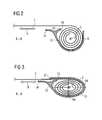
- FIG. 2schematically shows a sectional illustration along the line A-A from FIG. 1 ;
- FIG. 3shows a second alternative illustration of the cross-sectional spatial shape according to FIG. 2 ;
- FIG. 4shows a third alternative of the cross-sectional spatial shape according to FIG. 2 ;
- FIG. 5shows a fourth alternative of the cross-sectional spatial shape according to FIG. 2 .
- FIG. 6schematically shows a perspective illustration of a winding shaping device for a roller blind device according to the invention integrated into a roof frame of a sliding roof.
- a roller blind device 1has a roller blind web 2 which can be wound and unwound at least at one end about a winding axis 3 in a winding direction 4 .
- a roller blind winding 5is formed around the winding axis 3 .
- Self-winding spiral springs 7are connected to the roller blind web 2 at longitudinal edges 6 of the roller blind web 2 .
- the spiral springs 7may if appropriate be guided in guide rails (not shown), with the spiral springs 7 automatically rolling up into a spiral 8 about the winding axis 3 .
- a winding shaping device 9is arranged between the spiral springs 7 , that is to say in the region of the roller blind web 2 .
- the winding shaping device 9is of substantially channel-shaped design and extends in a transverse direction 10 of the roller blind device in a region between the spiral springs 7 , without interacting with said spiral springs 7 .
- a first free end region 11 and a second free end region 12 of the winding device 9are arranged with a minimum spacing a to the spiral spring 7 .
- the minimum spacing ais advantageously between 5 mm and 40 mm, in particular between 5 mm and 25 mm.
- the minimum spacing amay be of equal size or of different sizes at both sides of the roller blind web 2 .
- the winding shaping device 9borders a winding space 13 (cf. FIG. 2 ) in which the roller blind winding 5 is held in the partially or completely wound state of the roller blind web 2 .
- the roller blind winding 5has no winding core in the described exemplary embodiment.
- the winding axis 3is therefore not to be understood as a geometrically clearly defined winding axis but rather as a substantially resultant winding axis which, on account of the softness and deformability of the roller blind winding 5 formed from the roller blind web 2 , has an imaginary profile within the winding space 13 .
- Such an imaginary and desired profile of the winding axis 3can be influenced by means of the spatial shape of the winding shaping device 9 along the transverse direction 10 of the roller blind winding 5 . It is possible, for example, for a curvature of the winding shaping device 9 along the transverse direction 10 to lead to a curved arrangement or curved guidance of the roller blind winding 5 , so as in particular to enable matching of the roller blind winding profile in the transverse direction 10 to a roof curvature of a vehicle.
- FIG. 2shows a possible approximately circular cross-sectional spatial shape of the winding shaping device 9 along the section line A-A in FIG. 1 .
- Said sectionis situated approximately in the center of the roller blind winding 5 in relation to its longitudinal extent in the transverse direction 10 .
- the winding shaping device 9borders the winding space 13 , in which the roller blind winding 5 is arranged, in substantially the form of a channel.
- the winding shaping device 9has a free edge 14 which points in the winding direction 4 , in particular in the pulling-out direction of the roller blind web 2 .
- the free edge 14is assigned a stop rib 15 whose free edge 16 points counter to the pulling-out direction 4 .
- the stop rib 15serves, as the roller blind web 2 is pulled out, that is to say as the roller blind web 2 is pulled off the roller blind winding 5 , as a stop for the rest of the rolled winding and ensures that the roller blind web 2 is unwound without becoming jammed.
- the winding space 13 of the winding shaping device 9has an approximately circular spatial shape in cross section, such that an approximately circular roller blind winding 5 is formed as the roller blind web 2 is wound.
- the cross-sectional spatial shape of the winding space 13is of oval, flattened design, with a major axis HA of the oval being aligned approximately parallel to the plane of extent of the roller blind web 2 .
- the minor axis NAis arranged approximately vertically with respect to the roller blind web 2 .
- the cross-sectional spatial shape of the winding shaping device 9is likewise substantially oval, with the major axis HA being approximately perpendicular to the web plane of the roller blind web 2 . Accordingly, the minor axis NA is arranged substantially parallel to the roller blind web plane. Although this entails a taller structural shape in a direction perpendicular to the roller blind web plane, it is for example possible for an overall structural length of the roller blind device 1 to be minimized.
- the major axis HA of the oval of the winding space 13may also be arranged at an angle ⁇ with respect to the normal to the roller blind web plane.
- the angle ⁇may lie in the range between 0° and 90°, with it also being possible for the angle ⁇ to vary along the transverse direction 10 , such that it is possible to realize a helical “twisting” of the winding space in the transverse direction 10 .
- the roller blind winding 5is arranged relative to the roller blind web 2 or roller blind web plane such that the roller blind web plane extends away from the roller blind winding 5 approximately tangentially.
- the roller blind winding 5 or the winding axis 3 of the roller blind winding 5is at any rate arranged offset with respect to the roller blind web plane. If this is not desired, then it is possible by means of the cross-sectional shaping according to FIG. 5 for the winding axis 3 to be arranged approximately at the level of the roller blind web plane. In this way, the roller blind web 2 is firstly deflected out of the plane of the roller blind web 2 before being wound on the roller blind winding 5 . The roller blind web 2 then passes into a winding space 13 which is approximately droplet-shaped in cross section.
- the winding shaping device 9is formed for example with a cover 9 a which virtually completely surrounds the roller blind winding 5 and leaves free a slot opening 17 from which the roller blind web 2 can emerge.
- a cover 9 ais optional.
- the roller blind winding 5it is also possible for the roller blind winding 5 to be shaped and guided by means of a channel-shaped design of the winding shaping device 9 without a cover 9 a , since the roller blind winding 5 can be flattened in one region for example by means of the influence of gravity alone.
- the cross section of the winding space 3 which is bordered or defined by the winding shaping device 9is particularly advantageous for the cross section of the winding space 3 which is bordered or defined by the winding shaping device 9 to be of variable design along the transverse direction 10 . It is for example possible for a flattened spatial shape according to FIG. 3 or a shortened spatial shape according to FIG. 4 to be provided approximately in the center between the spiral springs 7 in the transverse direction 10 , and for the roller blind winding 5 to be shaped in an increasingly circular manner toward the spiral springs 7 . This results in continuous and slow, smooth matching of the roller blind winding cross section to the winding cross section of the spiral springs 7 which are arranged at the edge. In this way, an undesired formation of folds is prevented in particular.
- FIG. 6shows a possible arrangement of the winding shaping device 9 as an integrally formed or integral constituent part of a roof frame 19 of a sliding roof arrangement for a motor vehicle.
- the free end regions 11 and 12are arranged here such that free spaces 20 are formed in which the spiral springs 7 can wind and unwind freely without interacting with the winding shaping device 9 . This in particular minimizes the number of components for forming a sunshield roller blind for sliding roof arrangements.
- FIGS. 1 to 6illustrate a winding shaping device 9 , 9 a which is substantially formed in one piece in the transverse direction 10 . It is nevertheless also possible for a multiplicity of individual winding shaping devices 9 , which are for example of approximately clamp-like or clasp-like design, to be provided instead of a single, continuous winding shaping device 9 , 9 a . It is by all means also possible for gaps or spacings to be provided between the individual clasp-like winding shaping devices 9 , in which gaps or spacings the roller blind winding 5 runs freely without being guided or shaped. Such an embodiment is described and illustrated for example in the applicant's German patent application 10 2007 021 049. The content of said patent application, the priority of which is hereby claimed, is expressly included in the present patent application.
- the roller blind device according to the inventionmay in particular also have rotatably mounted winding elements which interact with the constant-force spring or with the spiral spring 7 .
- Winding elements of said typeare designed, for example in the German patent application 10 2007 021 049, as bolts.
- the entire content of the German patent application DE 10 2007 041 296.9is also included in this patent application.
- the present roller blind device according to the inventionmay of course also be easily combined with attachments, which have guide tracks, on guide rails according to said German patent application.
Landscapes
- Engineering & Computer Science (AREA)
- Mechanical Engineering (AREA)
- Operating, Guiding And Securing Of Roll- Type Closing Members (AREA)
Abstract
Description
- 1 Roller blind device
- 2 Roller blind web
- 3 Winding axis
- 4 Winding direction
- 5 Roller blind winding
- 6 Longitudinal edges
- 7 Spiral springs
- 8 Spiral
- 9 Winding shaping device
- 9aCover
- 10 Transverse direction
- 11 First free end region
- 12 Second free end region
- 13 Winding space
- 14 Free edge
- 15 Stop rib
- 16 Free edge
- 17 Slot opening
- 19 Roof frame
- 20 Free spaces
- HA Major axis
- NA Minor axis
- a Minimum spacing
- αAngle
Claims (15)
Applications Claiming Priority (6)
| Application Number | Priority Date | Filing Date | Title |
|---|---|---|---|
| DE200710021049DE102007021049B4 (en) | 2007-05-04 | 2007-05-04 | Roller blind device, in particular for a sunroof system |
| DE200710041296DE102007041296B4 (en) | 2007-08-31 | 2007-08-31 | Folding hood for a convertible vehicle |
| EP07017793AEP1992511B1 (en) | 2007-05-04 | 2007-09-11 | Roller blind device, in particular for a sliding roof system |
| EP07017793.6 | 2007-09-11 | ||
| EP07017793 | 2007-09-11 | ||
| PCT/DE2008/001082WO2009033439A1 (en) | 2007-05-04 | 2008-07-02 | Roller blind device, particularly for a sliding roof system |
Publications (2)
| Publication Number | Publication Date |
|---|---|
| US20110056632A1 US20110056632A1 (en) | 2011-03-10 |
| US8430148B2true US8430148B2 (en) | 2013-04-30 |
Family
ID=40452902
Family Applications (1)
| Application Number | Title | Priority Date | Filing Date |
|---|---|---|---|
| US12/675,386Expired - Fee RelatedUS8430148B2 (en) | 2007-05-04 | 2008-07-02 | Roller blind device |
Country Status (5)
| Country | Link |
|---|---|
| US (1) | US8430148B2 (en) |
| EP (1) | EP1992511B1 (en) |
| CN (1) | CN101848820B (en) |
| DE (2) | DE502007001356D1 (en) |
| WO (1) | WO2009033439A1 (en) |
Cited By (6)
| Publication number | Priority date | Publication date | Assignee | Title |
|---|---|---|---|---|
| US20110226426A1 (en)* | 2007-08-31 | 2011-09-22 | Webasto Ag | Blind Arrangement for a Motor Vehicle |
| US8973641B1 (en)* | 2012-10-31 | 2015-03-10 | Space Systems/Loral, Llc | Roll-up contamination cover |
| US20150316962A1 (en)* | 2012-11-23 | 2015-11-05 | Averly Ip Limited | Frame system for flexible panel |
| WO2016202505A1 (en)* | 2015-06-19 | 2016-12-22 | Webasto SE | Vehicle roof having a roller blind assembly |
| US20170138127A1 (en)* | 2008-08-26 | 2017-05-18 | Hunter Douglas Inc. | Roll-up retractable covering for architectural openings |
| US11993136B2 (en) | 2018-12-05 | 2024-05-28 | Bos Gmbh & Co. Kg | Roller blind device for a vehicle interior, and roller blind shaft for same |
Families Citing this family (13)
| Publication number | Priority date | Publication date | Assignee | Title |
|---|---|---|---|---|
| DE102009035427B4 (en) | 2009-07-31 | 2012-02-02 | Webasto Ag | Roller blind arrangement, in particular for a vehicle, and roof arrangement |
| FR2969538B1 (en)* | 2010-12-23 | 2013-01-18 | Webasto Systemes Carrosserie | CANVAS OCCULTATION DEVICE, IN PARTICULAR FOR A MOTOR VEHICLE |
| JP5993593B2 (en)* | 2012-03-21 | 2016-09-14 | 八千代工業株式会社 | Sunshade equipment |
| FR2990652B1 (en)* | 2012-05-15 | 2014-06-13 | Webasto Systemes Carrosserie | CURVED OCCULTATION DEVICE WITH REDUCED SIZE, IN PARTICULAR FOR A MOTOR VEHICLE. |
| JP2014189064A (en)* | 2013-03-26 | 2014-10-06 | Aisin Seiki Co Ltd | Vehicular roll shade device |
| EP2987668B1 (en)* | 2014-08-18 | 2019-04-24 | Inalfa Roof Systems Group B.V. | Sunshade assembly |
| EP2987667B1 (en) | 2014-08-18 | 2019-10-09 | Inalfa Roof Systems Group B.V. | Guide and sunshade assembly provided therewith |
| DE102015005167A1 (en)* | 2015-04-23 | 2016-10-27 | Webasto SE | Vehicle roof module with a roof element and a roller blind device |
| FR3038866B1 (en)* | 2015-07-17 | 2019-05-24 | Renault S.A.S. | AUTOMOBILE VEHICLE DECAPOTABLE |
| CN106904116B (en)* | 2017-04-26 | 2023-08-25 | 葛长虹 | Tarpaulin covering rebound device for truck carriage |
| CN112440697B (en) | 2019-08-27 | 2023-11-24 | 英纳法天窗系统集团有限公司 | Sunshade system and method for manufacturing components thereof |
| CN112009222B (en)* | 2020-07-28 | 2021-08-27 | 江苏科达车业有限公司 | Vehicle compartment cover and vehicle |
| DE102022101686A1 (en)* | 2022-01-25 | 2023-07-27 | Stobag Ag | Shading device and cloth for a shading device |
Citations (36)
| Publication number | Priority date | Publication date | Assignee | Title |
|---|---|---|---|---|
| US758016A (en)* | 1903-06-29 | 1904-04-19 | William R Mudd | Automatic cover for awnings. |
| US843837A (en)* | 1906-03-14 | 1907-02-12 | Wells Mcmaster | Map-case. |
| US1570016A (en)* | 1924-05-01 | 1926-01-19 | John C Truemper | Awning |
| US2204739A (en)* | 1939-03-10 | 1940-06-18 | Gordon Tuggle H | Glare shield |
| US2561188A (en)* | 1948-05-01 | 1951-07-17 | Marvin D Ferguson | Windshield protector |
| US2689002A (en)* | 1951-07-17 | 1954-09-14 | Rose Dominic J De | Trailer awning |
| US2773547A (en)* | 1953-09-11 | 1956-12-11 | Voss Hans Conrad | Roller mounting for tarpaulins |
| US4131269A (en)* | 1976-01-27 | 1978-12-26 | Hans Brattrud | Device for protection of vehicle windows against ice or frost |
| US4807684A (en)* | 1987-06-11 | 1989-02-28 | Melton John G | Roll up closet door |
| US4809760A (en)* | 1979-03-14 | 1989-03-07 | Lew Hyok S | Self-coiling partition |
| US4825921A (en)* | 1986-05-07 | 1989-05-02 | Rigter Steven M | Blinds, screens, partitions and doors |
| US5067546A (en)* | 1989-04-19 | 1991-11-26 | Ets Farnier & Penin | Roller blind for a motor vehicle and process for the production thereof |
| US5133585A (en)* | 1990-09-20 | 1992-07-28 | Hassan Shawky A | Visor for automobiles |
| US5271634A (en)* | 1992-03-16 | 1993-12-21 | Walton Sharon A | Method for covering shopping carts |
| US5365990A (en)* | 1991-02-18 | 1994-11-22 | Showa Orifa Co., Ltd. | Heat insulating shutter device |
| US5711568A (en)* | 1996-02-05 | 1998-01-27 | Diem; D.W. | Retractable cargo cover |
| US5775765A (en)* | 1996-08-26 | 1998-07-07 | Kintz; Robert A. | Truck bed tarp and storing system |
| US5860466A (en)* | 1996-02-02 | 1999-01-19 | Kao; Nien Tsu Tim | Windshield shelter |
| US5947544A (en)* | 1995-09-22 | 1999-09-07 | Hubeshi; Carmel | Electromechanical sun visor for motor vehicle windows |
| US6047762A (en)* | 1998-03-20 | 2000-04-11 | Prince Corporation | Shade control for a vehicle window |
| US6086133A (en)* | 1998-04-06 | 2000-07-11 | Alonso; Miguel | Vehicle window shade arrangement |
| US6250321B1 (en)* | 1999-01-30 | 2001-06-26 | Douglas B. Ernst | Awning apparatus for automobiles |
| EP1127722A1 (en) | 2000-02-25 | 2001-08-29 | Wagon Automotive Snc | Shading device for window and/or for vehicle opening, using ribs, and corresponding vehicle |
| US6309076B1 (en)* | 1994-12-29 | 2001-10-30 | Mcvicker Richard E. | Light barrier, screen or reflector |
| US6547307B2 (en)* | 2000-11-22 | 2003-04-15 | Bos Gmbh & Co. Kg | Windup window shade with warping compensation |
| US6848493B1 (en)* | 2002-08-14 | 2005-02-01 | Bos Gmbh & Co. Kg | Window shade with bi-directionally operating actuating elements |
| DE202005006415U1 (en) | 2005-04-21 | 2005-06-23 | Arvinmeritor Gmbh | Roller blind assembly for a vehicle roof has a wind-up aid arranged behind a guide for guiding the blind during winding out so that it engages with spiral springs during winding and unwinding |
| EP1584509A2 (en) | 2004-04-08 | 2005-10-12 | ArvinMeritor GmbH | Roller blind for sliding roof system |
| US6983786B2 (en)* | 2003-09-24 | 2006-01-10 | Ing-Wen Chen | Height-adjustable car curtain |
| US20070084572A1 (en)* | 2005-10-14 | 2007-04-19 | Mark Davenport | Protection device with replaceable adaptor parts |
| US20080061605A1 (en) | 2006-09-13 | 2008-03-13 | Michael Jugl | Roller blind system for a sliding roof |
| DE102007021049A1 (en) | 2007-05-04 | 2008-11-13 | Webasto Ag | Roller blind device, in particular for a sunroof system |
| DE102007041296A1 (en) | 2007-08-31 | 2009-03-05 | Webasto Ag | Roller blind device for sliding roof system of motor vehicle, has winding guide provided for forming and/or guiding roll lap, and cooperating exclusively with roller blind within blind regions between spiral springs |
| US7612938B2 (en)* | 2006-02-14 | 2009-11-03 | Seiko Epson Corporation | Portable projection screen assembly |
| US7823955B2 (en)* | 2006-03-08 | 2010-11-02 | C.R.F. Societa Consortile Per Azioni | Sunshade device for motor-vehicles, with shape memory actuator |
| US7984746B2 (en)* | 2008-05-06 | 2011-07-26 | GM Global Technology Operations LLC | Cover deploying system utilizing active material actuation |
- 2007
- 2007-09-11EPEP07017793Apatent/EP1992511B1/enactiveActive
- 2007-09-11DEDE502007001356Tpatent/DE502007001356D1/enactiveActive
- 2008
- 2008-07-02USUS12/675,386patent/US8430148B2/ennot_activeExpired - Fee Related
- 2008-07-02WOPCT/DE2008/001082patent/WO2009033439A1/enactiveApplication Filing
- 2008-07-02CNCN2008801063424Apatent/CN101848820B/enactiveActive
- 2008-07-02DEDE112008003125Tpatent/DE112008003125A5/ennot_activeCeased
Patent Citations (39)
| Publication number | Priority date | Publication date | Assignee | Title |
|---|---|---|---|---|
| US758016A (en)* | 1903-06-29 | 1904-04-19 | William R Mudd | Automatic cover for awnings. |
| US843837A (en)* | 1906-03-14 | 1907-02-12 | Wells Mcmaster | Map-case. |
| US1570016A (en)* | 1924-05-01 | 1926-01-19 | John C Truemper | Awning |
| US2204739A (en)* | 1939-03-10 | 1940-06-18 | Gordon Tuggle H | Glare shield |
| US2561188A (en)* | 1948-05-01 | 1951-07-17 | Marvin D Ferguson | Windshield protector |
| US2689002A (en)* | 1951-07-17 | 1954-09-14 | Rose Dominic J De | Trailer awning |
| US2773547A (en)* | 1953-09-11 | 1956-12-11 | Voss Hans Conrad | Roller mounting for tarpaulins |
| US4131269A (en)* | 1976-01-27 | 1978-12-26 | Hans Brattrud | Device for protection of vehicle windows against ice or frost |
| US4809760A (en)* | 1979-03-14 | 1989-03-07 | Lew Hyok S | Self-coiling partition |
| US4825921A (en)* | 1986-05-07 | 1989-05-02 | Rigter Steven M | Blinds, screens, partitions and doors |
| US4807684A (en)* | 1987-06-11 | 1989-02-28 | Melton John G | Roll up closet door |
| US5067546A (en)* | 1989-04-19 | 1991-11-26 | Ets Farnier & Penin | Roller blind for a motor vehicle and process for the production thereof |
| US5133585A (en)* | 1990-09-20 | 1992-07-28 | Hassan Shawky A | Visor for automobiles |
| US5365990A (en)* | 1991-02-18 | 1994-11-22 | Showa Orifa Co., Ltd. | Heat insulating shutter device |
| US5271634A (en)* | 1992-03-16 | 1993-12-21 | Walton Sharon A | Method for covering shopping carts |
| US6309076B1 (en)* | 1994-12-29 | 2001-10-30 | Mcvicker Richard E. | Light barrier, screen or reflector |
| US5947544A (en)* | 1995-09-22 | 1999-09-07 | Hubeshi; Carmel | Electromechanical sun visor for motor vehicle windows |
| US5860466A (en)* | 1996-02-02 | 1999-01-19 | Kao; Nien Tsu Tim | Windshield shelter |
| US5711568A (en)* | 1996-02-05 | 1998-01-27 | Diem; D.W. | Retractable cargo cover |
| US5775765A (en)* | 1996-08-26 | 1998-07-07 | Kintz; Robert A. | Truck bed tarp and storing system |
| US6047762A (en)* | 1998-03-20 | 2000-04-11 | Prince Corporation | Shade control for a vehicle window |
| US6086133A (en)* | 1998-04-06 | 2000-07-11 | Alonso; Miguel | Vehicle window shade arrangement |
| US6250321B1 (en)* | 1999-01-30 | 2001-06-26 | Douglas B. Ernst | Awning apparatus for automobiles |
| EP1127722A1 (en) | 2000-02-25 | 2001-08-29 | Wagon Automotive Snc | Shading device for window and/or for vehicle opening, using ribs, and corresponding vehicle |
| US6547307B2 (en)* | 2000-11-22 | 2003-04-15 | Bos Gmbh & Co. Kg | Windup window shade with warping compensation |
| US6848493B1 (en)* | 2002-08-14 | 2005-02-01 | Bos Gmbh & Co. Kg | Window shade with bi-directionally operating actuating elements |
| US6983786B2 (en)* | 2003-09-24 | 2006-01-10 | Ing-Wen Chen | Height-adjustable car curtain |
| EP1584509A2 (en) | 2004-04-08 | 2005-10-12 | ArvinMeritor GmbH | Roller blind for sliding roof system |
| US20050225122A1 (en) | 2004-04-08 | 2005-10-13 | Thomas Becher | Window blind for a sliding roof system |
| US7114766B2 (en)* | 2004-04-08 | 2006-10-03 | Arvinmeritor Gmbh | Window blind for a sliding roof system |
| DE202005006415U1 (en) | 2005-04-21 | 2005-06-23 | Arvinmeritor Gmbh | Roller blind assembly for a vehicle roof has a wind-up aid arranged behind a guide for guiding the blind during winding out so that it engages with spiral springs during winding and unwinding |
| US20070084572A1 (en)* | 2005-10-14 | 2007-04-19 | Mark Davenport | Protection device with replaceable adaptor parts |
| US7612938B2 (en)* | 2006-02-14 | 2009-11-03 | Seiko Epson Corporation | Portable projection screen assembly |
| US7823955B2 (en)* | 2006-03-08 | 2010-11-02 | C.R.F. Societa Consortile Per Azioni | Sunshade device for motor-vehicles, with shape memory actuator |
| US20080061605A1 (en) | 2006-09-13 | 2008-03-13 | Michael Jugl | Roller blind system for a sliding roof |
| EP1900560A1 (en) | 2006-09-13 | 2008-03-19 | ArvinMeritor GmbH | Sun blind system for sunroof |
| DE102007021049A1 (en) | 2007-05-04 | 2008-11-13 | Webasto Ag | Roller blind device, in particular for a sunroof system |
| DE102007041296A1 (en) | 2007-08-31 | 2009-03-05 | Webasto Ag | Roller blind device for sliding roof system of motor vehicle, has winding guide provided for forming and/or guiding roll lap, and cooperating exclusively with roller blind within blind regions between spiral springs |
| US7984746B2 (en)* | 2008-05-06 | 2011-07-26 | GM Global Technology Operations LLC | Cover deploying system utilizing active material actuation |
Cited By (11)
| Publication number | Priority date | Publication date | Assignee | Title |
|---|---|---|---|---|
| US20110226426A1 (en)* | 2007-08-31 | 2011-09-22 | Webasto Ag | Blind Arrangement for a Motor Vehicle |
| US9108491B2 (en)* | 2007-08-31 | 2015-08-18 | Webasto SE | Blind arrangement for a motor vehicle |
| US20170138127A1 (en)* | 2008-08-26 | 2017-05-18 | Hunter Douglas Inc. | Roll-up retractable covering for architectural openings |
| US10724298B2 (en)* | 2008-08-26 | 2020-07-28 | Hunter Douglas Inc. | Roll-up retractable covering for architectural openings |
| US8973641B1 (en)* | 2012-10-31 | 2015-03-10 | Space Systems/Loral, Llc | Roll-up contamination cover |
| US20150316962A1 (en)* | 2012-11-23 | 2015-11-05 | Averly Ip Limited | Frame system for flexible panel |
| WO2016202505A1 (en)* | 2015-06-19 | 2016-12-22 | Webasto SE | Vehicle roof having a roller blind assembly |
| CN107750208A (en)* | 2015-06-19 | 2018-03-02 | 韦巴斯托股份公司 | Vehicle roof with roller blind arrangement |
| US10569622B2 (en) | 2015-06-19 | 2020-02-25 | Webasto SE | Vehicle roof having a roller blind arrangement |
| DE102015109862B4 (en)* | 2015-06-19 | 2025-04-10 | Webasto SE | Vehicle roof with roller blind arrangement |
| US11993136B2 (en) | 2018-12-05 | 2024-05-28 | Bos Gmbh & Co. Kg | Roller blind device for a vehicle interior, and roller blind shaft for same |
Also Published As
| Publication number | Publication date |
|---|---|
| DE502007001356D1 (en) | 2009-10-01 |
| CN101848820B (en) | 2012-08-22 |
| EP1992511A3 (en) | 2008-12-24 |
| WO2009033439A1 (en) | 2009-03-19 |
| CN101848820A (en) | 2010-09-29 |
| US20110056632A1 (en) | 2011-03-10 |
| EP1992511A2 (en) | 2008-11-19 |
| DE112008003125A5 (en) | 2010-08-19 |
| EP1992511B1 (en) | 2009-08-19 |
Similar Documents
| Publication | Publication Date | Title |
|---|---|---|
| US8430148B2 (en) | Roller blind device | |
| CN103481753B (en) | Solar protection devices | |
| US20110226426A1 (en) | Blind Arrangement for a Motor Vehicle | |
| US7059651B2 (en) | Sunshade system for a motor vehicle | |
| US8256492B2 (en) | Frame-mounted sunshade device | |
| ES2456347T3 (en) | Visor-sliding sun visor on bar | |
| US20120285638A1 (en) | Roller blind system | |
| US9315090B2 (en) | Ventilation arrangements for motor vehicles | |
| US20040040676A1 (en) | Shade tarp as sun shield | |
| KR101601497B1 (en) | Roller blinds for car a curtain device | |
| KR20130081207A (en) | Vehicle window shade device | |
| US20160009165A1 (en) | Roll shade apparatus for vehicle | |
| CN101120855A (en) | Hand-operated curtain with automatic drawing back function | |
| KR20130021341A (en) | Sunroof unit and vehicle with a sunroof unit | |
| US20030116997A1 (en) | Sunshade device with a curved screen | |
| DE102017125721B3 (en) | Shading roller blind for a roof window of a motor vehicle | |
| US20050263257A1 (en) | Extraction profile with adjustable centering mechanism | |
| US8291962B2 (en) | Window coverings | |
| EP1904325A1 (en) | Roller blind arrangement with an improved guiding system | |
| US20050211390A1 (en) | Shading device for automobile | |
| US8523277B2 (en) | Sunroof mounting device | |
| EP2508375B1 (en) | Rollo assembly and open roof construction provided therewith | |
| US20090301666A1 (en) | Shade arrangement for a motor vehicle | |
| KR20130106790A (en) | Protective device for a vehicle passenger compartment | |
| EP2628887B1 (en) | Screen device |
Legal Events
| Date | Code | Title | Description |
|---|---|---|---|
| AS | Assignment | Owner name:WEBASTO AG, GERMANY Free format text:ASSIGNMENT OF ASSIGNORS INTEREST;ASSIGNORS:THALHAMMER, MARCO;SCHULZ, HORST-MARTIN;HARNISCHFEGER, BERNHARD;AND OTHERS;SIGNING DATES FROM 20100305 TO 20100325;REEL/FRAME:024307/0395 | |
| STCF | Information on status: patent grant | Free format text:PATENTED CASE | |
| AS | Assignment | Owner name:WEBASTO SE, GERMANY Free format text:CHANGE OF NAME;ASSIGNOR:WEBASTO AG;REEL/FRAME:032175/0369 Effective date:20120712 | |
| FPAY | Fee payment | Year of fee payment:4 | |
| MAFP | Maintenance fee payment | Free format text:PAYMENT OF MAINTENANCE FEE, 8TH YEAR, LARGE ENTITY (ORIGINAL EVENT CODE: M1552); ENTITY STATUS OF PATENT OWNER: LARGE ENTITY Year of fee payment:8 | |
| FEPP | Fee payment procedure | Free format text:MAINTENANCE FEE REMINDER MAILED (ORIGINAL EVENT CODE: REM.); ENTITY STATUS OF PATENT OWNER: LARGE ENTITY | |
| LAPS | Lapse for failure to pay maintenance fees | Free format text:PATENT EXPIRED FOR FAILURE TO PAY MAINTENANCE FEES (ORIGINAL EVENT CODE: EXP.); ENTITY STATUS OF PATENT OWNER: LARGE ENTITY | |
| STCH | Information on status: patent discontinuation | Free format text:PATENT EXPIRED DUE TO NONPAYMENT OF MAINTENANCE FEES UNDER 37 CFR 1.362 | |
| FP | Lapsed due to failure to pay maintenance fee | Effective date:20250430 |