US8430147B2 - Machine and methods for the manufacture of air-filled cushions - Google Patents
Machine and methods for the manufacture of air-filled cushionsDownload PDFInfo
- Publication number
- US8430147B2 US8430147B2US12/546,472US54647209AUS8430147B2US 8430147 B2US8430147 B2US 8430147B2US 54647209 AUS54647209 AUS 54647209AUS 8430147 B2US8430147 B2US 8430147B2
- Authority
- US
- United States
- Prior art keywords
- machine
- layers
- plastic
- tubing
- sealing
- Prior art date
- Legal status (The legal status is an assumption and is not a legal conclusion. Google has not performed a legal analysis and makes no representation as to the accuracy of the status listed.)
- Active, expires
Links
Images


Classifications
- B—PERFORMING OPERATIONS; TRANSPORTING
- B65—CONVEYING; PACKING; STORING; HANDLING THIN OR FILAMENTARY MATERIAL
- B65B—MACHINES, APPARATUS OR DEVICES FOR, OR METHODS OF, PACKAGING ARTICLES OR MATERIALS; UNPACKING
- B65B1/00—Packaging fluent solid material, e.g. powders, granular or loose fibrous material, loose masses of small articles, in individual containers or receptacles, e.g. bags, sacks, boxes, cartons, cans, or jars
- B65B1/04—Methods of, or means for, filling the material into the containers or receptacles
- B—PERFORMING OPERATIONS; TRANSPORTING
- B29—WORKING OF PLASTICS; WORKING OF SUBSTANCES IN A PLASTIC STATE IN GENERAL
- B29C—SHAPING OR JOINING OF PLASTICS; SHAPING OF MATERIAL IN A PLASTIC STATE, NOT OTHERWISE PROVIDED FOR; AFTER-TREATMENT OF THE SHAPED PRODUCTS, e.g. REPAIRING
- B29C65/00—Joining or sealing of preformed parts, e.g. welding of plastics materials; Apparatus therefor
- B29C65/02—Joining or sealing of preformed parts, e.g. welding of plastics materials; Apparatus therefor by heating, with or without pressure
- B29C65/18—Joining or sealing of preformed parts, e.g. welding of plastics materials; Apparatus therefor by heating, with or without pressure using heated tools
- B—PERFORMING OPERATIONS; TRANSPORTING
- B29—WORKING OF PLASTICS; WORKING OF SUBSTANCES IN A PLASTIC STATE IN GENERAL
- B29C—SHAPING OR JOINING OF PLASTICS; SHAPING OF MATERIAL IN A PLASTIC STATE, NOT OTHERWISE PROVIDED FOR; AFTER-TREATMENT OF THE SHAPED PRODUCTS, e.g. REPAIRING
- B29C65/00—Joining or sealing of preformed parts, e.g. welding of plastics materials; Apparatus therefor
- B29C65/78—Means for handling the parts to be joined, e.g. for making containers or hollow articles, e.g. means for handling sheets, plates, web-like materials, tubular articles, hollow articles or elements to be joined therewith; Means for discharging the joined articles from the joining apparatus
- B29C65/7858—Means for handling the parts to be joined, e.g. for making containers or hollow articles, e.g. means for handling sheets, plates, web-like materials, tubular articles, hollow articles or elements to be joined therewith; Means for discharging the joined articles from the joining apparatus characterised by the feeding movement of the parts to be joined
- B29C65/7861—In-line machines, i.e. feeding, joining and discharging are in one production line
- B29C65/787—In-line machines, i.e. feeding, joining and discharging are in one production line using conveyor belts or conveyor chains
- B—PERFORMING OPERATIONS; TRANSPORTING
- B29—WORKING OF PLASTICS; WORKING OF SUBSTANCES IN A PLASTIC STATE IN GENERAL
- B29C—SHAPING OR JOINING OF PLASTICS; SHAPING OF MATERIAL IN A PLASTIC STATE, NOT OTHERWISE PROVIDED FOR; AFTER-TREATMENT OF THE SHAPED PRODUCTS, e.g. REPAIRING
- B29C66/00—General aspects of processes or apparatus for joining preformed parts
- B29C66/01—General aspects dealing with the joint area or with the area to be joined
- B29C66/05—Particular design of joint configurations
- B29C66/10—Particular design of joint configurations particular design of the joint cross-sections
- B29C66/11—Joint cross-sections comprising a single joint-segment, i.e. one of the parts to be joined comprising a single joint-segment in the joint cross-section
- B29C66/112—Single lapped joints
- B29C66/1122—Single lap to lap joints, i.e. overlap joints
- B—PERFORMING OPERATIONS; TRANSPORTING
- B29—WORKING OF PLASTICS; WORKING OF SUBSTANCES IN A PLASTIC STATE IN GENERAL
- B29C—SHAPING OR JOINING OF PLASTICS; SHAPING OF MATERIAL IN A PLASTIC STATE, NOT OTHERWISE PROVIDED FOR; AFTER-TREATMENT OF THE SHAPED PRODUCTS, e.g. REPAIRING
- B29C66/00—General aspects of processes or apparatus for joining preformed parts
- B29C66/40—General aspects of joining substantially flat articles, e.g. plates, sheets or web-like materials; Making flat seams in tubular or hollow articles; Joining single elements to substantially flat surfaces
- B29C66/41—Joining substantially flat articles ; Making flat seams in tubular or hollow articles
- B29C66/43—Joining a relatively small portion of the surface of said articles
- B29C66/439—Joining sheets for making inflated articles without using a mould
- B—PERFORMING OPERATIONS; TRANSPORTING
- B29—WORKING OF PLASTICS; WORKING OF SUBSTANCES IN A PLASTIC STATE IN GENERAL
- B29C—SHAPING OR JOINING OF PLASTICS; SHAPING OF MATERIAL IN A PLASTIC STATE, NOT OTHERWISE PROVIDED FOR; AFTER-TREATMENT OF THE SHAPED PRODUCTS, e.g. REPAIRING
- B29C66/00—General aspects of processes or apparatus for joining preformed parts
- B29C66/80—General aspects of machine operations or constructions and parts thereof
- B29C66/81—General aspects of the pressing elements, i.e. the elements applying pressure on the parts to be joined in the area to be joined, e.g. the welding jaws or clamps
- B29C66/814—General aspects of the pressing elements, i.e. the elements applying pressure on the parts to be joined in the area to be joined, e.g. the welding jaws or clamps characterised by the design of the pressing elements, e.g. of the welding jaws or clamps
- B29C66/8145—General aspects of the pressing elements, i.e. the elements applying pressure on the parts to be joined in the area to be joined, e.g. the welding jaws or clamps characterised by the design of the pressing elements, e.g. of the welding jaws or clamps characterised by the constructional aspects of the pressing elements, e.g. of the welding jaws or clamps
- B29C66/81463—General aspects of the pressing elements, i.e. the elements applying pressure on the parts to be joined in the area to be joined, e.g. the welding jaws or clamps characterised by the design of the pressing elements, e.g. of the welding jaws or clamps characterised by the constructional aspects of the pressing elements, e.g. of the welding jaws or clamps comprising a plurality of single pressing elements, e.g. a plurality of sonotrodes, or comprising a plurality of single counter-pressing elements, e.g. a plurality of anvils, said plurality of said single elements being suitable for making a single joint
- B29C66/81465—General aspects of the pressing elements, i.e. the elements applying pressure on the parts to be joined in the area to be joined, e.g. the welding jaws or clamps characterised by the design of the pressing elements, e.g. of the welding jaws or clamps characterised by the constructional aspects of the pressing elements, e.g. of the welding jaws or clamps comprising a plurality of single pressing elements, e.g. a plurality of sonotrodes, or comprising a plurality of single counter-pressing elements, e.g. a plurality of anvils, said plurality of said single elements being suitable for making a single joint one placed behind the other in a single row in the feed direction
- B—PERFORMING OPERATIONS; TRANSPORTING
- B29—WORKING OF PLASTICS; WORKING OF SUBSTANCES IN A PLASTIC STATE IN GENERAL
- B29C—SHAPING OR JOINING OF PLASTICS; SHAPING OF MATERIAL IN A PLASTIC STATE, NOT OTHERWISE PROVIDED FOR; AFTER-TREATMENT OF THE SHAPED PRODUCTS, e.g. REPAIRING
- B29C66/00—General aspects of processes or apparatus for joining preformed parts
- B29C66/80—General aspects of machine operations or constructions and parts thereof
- B29C66/81—General aspects of the pressing elements, i.e. the elements applying pressure on the parts to be joined in the area to be joined, e.g. the welding jaws or clamps
- B29C66/816—General aspects of the pressing elements, i.e. the elements applying pressure on the parts to be joined in the area to be joined, e.g. the welding jaws or clamps characterised by the mounting of the pressing elements, e.g. of the welding jaws or clamps
- B29C66/8161—General aspects of the pressing elements, i.e. the elements applying pressure on the parts to be joined in the area to be joined, e.g. the welding jaws or clamps characterised by the mounting of the pressing elements, e.g. of the welding jaws or clamps said pressing elements being supported or backed-up by springs or by resilient material
- B—PERFORMING OPERATIONS; TRANSPORTING
- B29—WORKING OF PLASTICS; WORKING OF SUBSTANCES IN A PLASTIC STATE IN GENERAL
- B29C—SHAPING OR JOINING OF PLASTICS; SHAPING OF MATERIAL IN A PLASTIC STATE, NOT OTHERWISE PROVIDED FOR; AFTER-TREATMENT OF THE SHAPED PRODUCTS, e.g. REPAIRING
- B29C66/00—General aspects of processes or apparatus for joining preformed parts
- B29C66/80—General aspects of machine operations or constructions and parts thereof
- B29C66/82—Pressure application arrangements, e.g. transmission or actuating mechanisms for joining tools or clamps
- B29C66/822—Transmission mechanisms
- B29C66/8221—Scissor or lever mechanisms, i.e. involving a pivot point
- B—PERFORMING OPERATIONS; TRANSPORTING
- B29—WORKING OF PLASTICS; WORKING OF SUBSTANCES IN A PLASTIC STATE IN GENERAL
- B29C—SHAPING OR JOINING OF PLASTICS; SHAPING OF MATERIAL IN A PLASTIC STATE, NOT OTHERWISE PROVIDED FOR; AFTER-TREATMENT OF THE SHAPED PRODUCTS, e.g. REPAIRING
- B29C66/00—General aspects of processes or apparatus for joining preformed parts
- B29C66/80—General aspects of machine operations or constructions and parts thereof
- B29C66/83—General aspects of machine operations or constructions and parts thereof characterised by the movement of the joining or pressing tools
- B29C66/834—General aspects of machine operations or constructions and parts thereof characterised by the movement of the joining or pressing tools moving with the parts to be joined
- B29C66/8341—Roller, cylinder or drum types; Band or belt types; Ball types
- B29C66/83421—Roller, cylinder or drum types; Band or belt types; Ball types band or belt types
- B29C66/83423—Roller, cylinder or drum types; Band or belt types; Ball types band or belt types cooperating bands or belts
- B—PERFORMING OPERATIONS; TRANSPORTING
- B29—WORKING OF PLASTICS; WORKING OF SUBSTANCES IN A PLASTIC STATE IN GENERAL
- B29C—SHAPING OR JOINING OF PLASTICS; SHAPING OF MATERIAL IN A PLASTIC STATE, NOT OTHERWISE PROVIDED FOR; AFTER-TREATMENT OF THE SHAPED PRODUCTS, e.g. REPAIRING
- B29C66/00—General aspects of processes or apparatus for joining preformed parts
- B29C66/80—General aspects of machine operations or constructions and parts thereof
- B29C66/87—Auxiliary operations or devices
- B29C66/872—Starting or stopping procedures
- B—PERFORMING OPERATIONS; TRANSPORTING
- B29—WORKING OF PLASTICS; WORKING OF SUBSTANCES IN A PLASTIC STATE IN GENERAL
- B29C—SHAPING OR JOINING OF PLASTICS; SHAPING OF MATERIAL IN A PLASTIC STATE, NOT OTHERWISE PROVIDED FOR; AFTER-TREATMENT OF THE SHAPED PRODUCTS, e.g. REPAIRING
- B29C66/00—General aspects of processes or apparatus for joining preformed parts
- B29C66/80—General aspects of machine operations or constructions and parts thereof
- B29C66/87—Auxiliary operations or devices
- B29C66/874—Safety measures or devices
- B29C66/8744—Preventing overheating of the parts to be joined, e.g. if the machine stops or slows down
- B29C66/87443—Preventing overheating of the parts to be joined, e.g. if the machine stops or slows down by withdrawing the heating tools
- B—PERFORMING OPERATIONS; TRANSPORTING
- B31—MAKING ARTICLES OF PAPER, CARDBOARD OR MATERIAL WORKED IN A MANNER ANALOGOUS TO PAPER; WORKING PAPER, CARDBOARD OR MATERIAL WORKED IN A MANNER ANALOGOUS TO PAPER
- B31D—MAKING ARTICLES OF PAPER, CARDBOARD OR MATERIAL WORKED IN A MANNER ANALOGOUS TO PAPER, NOT PROVIDED FOR IN SUBCLASSES B31B OR B31C
- B31D5/00—Multiple-step processes for making three-dimensional articles ; Making three-dimensional articles
- B31D5/0039—Multiple-step processes for making three-dimensional articles ; Making three-dimensional articles for making dunnage or cushion pads
- B31D5/0073—Multiple-step processes for making three-dimensional articles ; Making three-dimensional articles for making dunnage or cushion pads including pillow forming
- B—PERFORMING OPERATIONS; TRANSPORTING
- B65—CONVEYING; PACKING; STORING; HANDLING THIN OR FILAMENTARY MATERIAL
- B65B—MACHINES, APPARATUS OR DEVICES FOR, OR METHODS OF, PACKAGING ARTICLES OR MATERIALS; UNPACKING
- B65B1/00—Packaging fluent solid material, e.g. powders, granular or loose fibrous material, loose masses of small articles, in individual containers or receptacles, e.g. bags, sacks, boxes, cartons, cans, or jars
- B65B1/02—Machines characterised by the incorporation of means for making the containers or receptacles
- B—PERFORMING OPERATIONS; TRANSPORTING
- B65—CONVEYING; PACKING; STORING; HANDLING THIN OR FILAMENTARY MATERIAL
- B65B—MACHINES, APPARATUS OR DEVICES FOR, OR METHODS OF, PACKAGING ARTICLES OR MATERIALS; UNPACKING
- B65B41/00—Supplying or feeding container-forming sheets or wrapping material
- B65B41/12—Feeding webs from rolls
- B—PERFORMING OPERATIONS; TRANSPORTING
- B65—CONVEYING; PACKING; STORING; HANDLING THIN OR FILAMENTARY MATERIAL
- B65B—MACHINES, APPARATUS OR DEVICES FOR, OR METHODS OF, PACKAGING ARTICLES OR MATERIALS; UNPACKING
- B65B51/00—Devices for, or methods of, sealing or securing package folds or closures; Devices for gathering or twisting wrappers, or necks of bags
- B65B51/10—Applying or generating heat or pressure or combinations thereof
- B65B51/26—Devices specially adapted for producing transverse or longitudinal seams in webs or tubes
- B65B51/30—Devices, e.g. jaws, for applying pressure and heat, e.g. for subdividing filled tubes
- B—PERFORMING OPERATIONS; TRANSPORTING
- B65—CONVEYING; PACKING; STORING; HANDLING THIN OR FILAMENTARY MATERIAL
- B65B—MACHINES, APPARATUS OR DEVICES FOR, OR METHODS OF, PACKAGING ARTICLES OR MATERIALS; UNPACKING
- B65B61/00—Auxiliary devices, not otherwise provided for, for operating on sheets, blanks, webs, binding material, containers or packages
- B65B61/02—Auxiliary devices, not otherwise provided for, for operating on sheets, blanks, webs, binding material, containers or packages for perforating, scoring, slitting, or applying code or date marks on material prior to packaging
- B—PERFORMING OPERATIONS; TRANSPORTING
- B29—WORKING OF PLASTICS; WORKING OF SUBSTANCES IN A PLASTIC STATE IN GENERAL
- B29C—SHAPING OR JOINING OF PLASTICS; SHAPING OF MATERIAL IN A PLASTIC STATE, NOT OTHERWISE PROVIDED FOR; AFTER-TREATMENT OF THE SHAPED PRODUCTS, e.g. REPAIRING
- B29C66/00—General aspects of processes or apparatus for joining preformed parts
- B29C66/90—Measuring or controlling the joining process
- B29C66/91—Measuring or controlling the joining process by measuring or controlling the temperature, the heat or the thermal flux
- B29C66/914—Measuring or controlling the joining process by measuring or controlling the temperature, the heat or the thermal flux by controlling or regulating the temperature, the heat or the thermal flux
- B29C66/9141—Measuring or controlling the joining process by measuring or controlling the temperature, the heat or the thermal flux by controlling or regulating the temperature, the heat or the thermal flux by controlling or regulating the temperature
- B29C66/91431—Measuring or controlling the joining process by measuring or controlling the temperature, the heat or the thermal flux by controlling or regulating the temperature, the heat or the thermal flux by controlling or regulating the temperature the temperature being kept constant over time
- B—PERFORMING OPERATIONS; TRANSPORTING
- B29—WORKING OF PLASTICS; WORKING OF SUBSTANCES IN A PLASTIC STATE IN GENERAL
- B29C—SHAPING OR JOINING OF PLASTICS; SHAPING OF MATERIAL IN A PLASTIC STATE, NOT OTHERWISE PROVIDED FOR; AFTER-TREATMENT OF THE SHAPED PRODUCTS, e.g. REPAIRING
- B29C66/00—General aspects of processes or apparatus for joining preformed parts
- B29C66/90—Measuring or controlling the joining process
- B29C66/91—Measuring or controlling the joining process by measuring or controlling the temperature, the heat or the thermal flux
- B29C66/914—Measuring or controlling the joining process by measuring or controlling the temperature, the heat or the thermal flux by controlling or regulating the temperature, the heat or the thermal flux
- B29C66/9161—Measuring or controlling the joining process by measuring or controlling the temperature, the heat or the thermal flux by controlling or regulating the temperature, the heat or the thermal flux by controlling or regulating the heat or the thermal flux, i.e. the heat flux
- B29C66/91641—Measuring or controlling the joining process by measuring or controlling the temperature, the heat or the thermal flux by controlling or regulating the temperature, the heat or the thermal flux by controlling or regulating the heat or the thermal flux, i.e. the heat flux the heat or the thermal flux being non-constant over time
- B—PERFORMING OPERATIONS; TRANSPORTING
- B29—WORKING OF PLASTICS; WORKING OF SUBSTANCES IN A PLASTIC STATE IN GENERAL
- B29C—SHAPING OR JOINING OF PLASTICS; SHAPING OF MATERIAL IN A PLASTIC STATE, NOT OTHERWISE PROVIDED FOR; AFTER-TREATMENT OF THE SHAPED PRODUCTS, e.g. REPAIRING
- B29C66/00—General aspects of processes or apparatus for joining preformed parts
- B29C66/90—Measuring or controlling the joining process
- B29C66/93—Measuring or controlling the joining process by measuring or controlling the speed
- B29C66/934—Measuring or controlling the joining process by measuring or controlling the speed by controlling or regulating the speed
- B—PERFORMING OPERATIONS; TRANSPORTING
- B31—MAKING ARTICLES OF PAPER, CARDBOARD OR MATERIAL WORKED IN A MANNER ANALOGOUS TO PAPER; WORKING PAPER, CARDBOARD OR MATERIAL WORKED IN A MANNER ANALOGOUS TO PAPER
- B31D—MAKING ARTICLES OF PAPER, CARDBOARD OR MATERIAL WORKED IN A MANNER ANALOGOUS TO PAPER, NOT PROVIDED FOR IN SUBCLASSES B31B OR B31C
- B31D2205/00—Multiple-step processes for making three-dimensional articles
- B31D2205/0005—Multiple-step processes for making three-dimensional articles for making dunnage or cushion pads
- B31D2205/0011—Multiple-step processes for making three-dimensional articles for making dunnage or cushion pads including particular additional operations
- B31D2205/0017—Providing stock material in a particular form
- B31D2205/0023—Providing stock material in a particular form as web from a roll
- B—PERFORMING OPERATIONS; TRANSPORTING
- B31—MAKING ARTICLES OF PAPER, CARDBOARD OR MATERIAL WORKED IN A MANNER ANALOGOUS TO PAPER; WORKING PAPER, CARDBOARD OR MATERIAL WORKED IN A MANNER ANALOGOUS TO PAPER
- B31D—MAKING ARTICLES OF PAPER, CARDBOARD OR MATERIAL WORKED IN A MANNER ANALOGOUS TO PAPER, NOT PROVIDED FOR IN SUBCLASSES B31B OR B31C
- B31D2205/00—Multiple-step processes for making three-dimensional articles
- B31D2205/0005—Multiple-step processes for making three-dimensional articles for making dunnage or cushion pads
- B31D2205/0011—Multiple-step processes for making three-dimensional articles for making dunnage or cushion pads including particular additional operations
- B31D2205/0047—Feeding, guiding or shaping the material
- B—PERFORMING OPERATIONS; TRANSPORTING
- B31—MAKING ARTICLES OF PAPER, CARDBOARD OR MATERIAL WORKED IN A MANNER ANALOGOUS TO PAPER; WORKING PAPER, CARDBOARD OR MATERIAL WORKED IN A MANNER ANALOGOUS TO PAPER
- B31D—MAKING ARTICLES OF PAPER, CARDBOARD OR MATERIAL WORKED IN A MANNER ANALOGOUS TO PAPER, NOT PROVIDED FOR IN SUBCLASSES B31B OR B31C
- B31D2205/00—Multiple-step processes for making three-dimensional articles
- B31D2205/0005—Multiple-step processes for making three-dimensional articles for making dunnage or cushion pads
- B31D2205/0011—Multiple-step processes for making three-dimensional articles for making dunnage or cushion pads including particular additional operations
- B31D2205/0052—Perforating; Forming lines of weakness
- B—PERFORMING OPERATIONS; TRANSPORTING
- B31—MAKING ARTICLES OF PAPER, CARDBOARD OR MATERIAL WORKED IN A MANNER ANALOGOUS TO PAPER; WORKING PAPER, CARDBOARD OR MATERIAL WORKED IN A MANNER ANALOGOUS TO PAPER
- B31D—MAKING ARTICLES OF PAPER, CARDBOARD OR MATERIAL WORKED IN A MANNER ANALOGOUS TO PAPER, NOT PROVIDED FOR IN SUBCLASSES B31B OR B31C
- B31D2205/00—Multiple-step processes for making three-dimensional articles
- B31D2205/0005—Multiple-step processes for making three-dimensional articles for making dunnage or cushion pads
- B31D2205/0076—Multiple-step processes for making three-dimensional articles for making dunnage or cushion pads involving particular machinery details
- B31D2205/0082—General layout of the machinery or relative arrangement of its subunits
- B—PERFORMING OPERATIONS; TRANSPORTING
- B32—LAYERED PRODUCTS
- B32B—LAYERED PRODUCTS, i.e. PRODUCTS BUILT-UP OF STRATA OF FLAT OR NON-FLAT, e.g. CELLULAR OR HONEYCOMB, FORM
- B32B2553/00—Packaging equipment or accessories not otherwise provided for
- B32B2553/02—Shock absorbing
- B32B2553/023—Shock absorbing for use in loose form, e.g. dunnage
- Y—GENERAL TAGGING OF NEW TECHNOLOGICAL DEVELOPMENTS; GENERAL TAGGING OF CROSS-SECTIONAL TECHNOLOGIES SPANNING OVER SEVERAL SECTIONS OF THE IPC; TECHNICAL SUBJECTS COVERED BY FORMER USPC CROSS-REFERENCE ART COLLECTIONS [XRACs] AND DIGESTS
- Y10—TECHNICAL SUBJECTS COVERED BY FORMER USPC
- Y10T—TECHNICAL SUBJECTS COVERED BY FORMER US CLASSIFICATION
- Y10T156/00—Adhesive bonding and miscellaneous chemical manufacture
- Y10T156/12—Surface bonding means and/or assembly means with cutting, punching, piercing, severing or tearing
- Y—GENERAL TAGGING OF NEW TECHNOLOGICAL DEVELOPMENTS; GENERAL TAGGING OF CROSS-SECTIONAL TECHNOLOGIES SPANNING OVER SEVERAL SECTIONS OF THE IPC; TECHNICAL SUBJECTS COVERED BY FORMER USPC CROSS-REFERENCE ART COLLECTIONS [XRACs] AND DIGESTS
- Y10—TECHNICAL SUBJECTS COVERED BY FORMER USPC
- Y10T—TECHNICAL SUBJECTS COVERED BY FORMER US CLASSIFICATION
- Y10T156/00—Adhesive bonding and miscellaneous chemical manufacture
- Y10T156/17—Surface bonding means and/or assemblymeans with work feeding or handling means
- Y10T156/1702—For plural parts or plural areas of single part
- Y10T156/1712—Indefinite or running length work
- Y10T156/1715—Means joining indefinite length work edge to edge
- Y—GENERAL TAGGING OF NEW TECHNOLOGICAL DEVELOPMENTS; GENERAL TAGGING OF CROSS-SECTIONAL TECHNOLOGIES SPANNING OVER SEVERAL SECTIONS OF THE IPC; TECHNICAL SUBJECTS COVERED BY FORMER USPC CROSS-REFERENCE ART COLLECTIONS [XRACs] AND DIGESTS
- Y10—TECHNICAL SUBJECTS COVERED BY FORMER USPC
- Y10T—TECHNICAL SUBJECTS COVERED BY FORMER US CLASSIFICATION
- Y10T428/00—Stock material or miscellaneous articles
- Y10T428/13—Hollow or container type article [e.g., tube, vase, etc.]
Definitions
- This inventionrelates to improvements in the manufacture of air filled cushions.
- this inventionrelates to air cushions of thin-walled plastic sheet, which can be used as infill or cushioning in the packaging and transportation of fragile articles.
- air filled cushionsare manufactured from a roll of plastic tubing.
- a typical example of a method of manufacturing these cushionsis described in International Patent Application WO 01/21391, incorporated by reference herein in its entirety.
- the plastic tubingis drawn through the machine from a supply roll.
- the walls of the plastic tubingare separated by drawing the tubing over a separator member.
- Airis then injected into the space between the wall through a needle, which pierces one of the walls of the tube, the hole left by the needle later being isolated by a heat seal.
- This processrequires careful coordination of the position of the separator member and the air injecting needle, and good control of the air injecting needle so that only one wall of the tubing is pierced.
- a different way of manufacturing air filled cushionsis to pre-perforate the plastic tubing and blow air into the tube through the perforations. Again, this requires careful coordination of the position of the injection head and the plastic tubing.
- the inventionincludes a machine for the production of air filled cushions including a drive mechanism which is operative continuously to move plastic tubing through the machine along a predefined path, and an injector located in the predefined path disposed within the plastic tubing as the tubing is moved through the machine.
- the injectorhas an inlet and an outlet and the drive mechanism is operative to move the plastic tubing over the outlet of the injector, whereby air can be injected through the injector into the plastic tubing.
- the pressureis less than 5 psi, and most conveniently a pressure of 1-2 psi is used.
- the injectorcan be provided with a single outlet, but preferably has two or more outlets, arranged around its periphery, each outlet being operative to inflate a portion of the plastic tubing.
- the injectoris provided with a cutter, upstream of the inlet, to cut a surface of the plastic tubing, allowing the plastic tubing to pass around the inlet.
- the machinecan be adapted for use with plastic tubing having two rows of transverse, parallel, welds, the welds of each row extending toward a longitudinal centerline of the tubing from a respective one of the side edges.
- a weld of one rowcan be generally co-linear with a weld of the other row, with an unwelded section between them.
- the injectorcan be located generally within the unwelded section, whereby at least one outlet of the separator member can be operative to inflate portions of the plastic tubing defined by adjacent welds in each row.
- the machinecan include a sealing mechanism.
- the sealing mechanismcan be located downstream of the outlet so as to seal the plastic tubing longitudinally.
- the sealing mechanismis a heat sealer mechanism, which has an operating position in which it abuts the plastic tubing and a standby position in which it is removed from the plastic tubing and the heat sealer can be moved from the operating position to the standby position when the machine is stopped.
- the heat sealercomprises at least two spaced elongate bars, which are preferably generally equal in length to the air filled cushions produced by the machine. This ensures a good seal can be achieved.
- the machinecan further include a perforator.
- the perforatorcan be located downstream of the sealing mechanism, whereby the perforator is operative to perforate the plastic tubing longitudinally.
- the machinefurther comprises a barrier, upstream of the injector, which is operative to maintain portions of the tubing deflated.
- the machinecan also include a pressure sensor which is operative to place an outlet in fluid communication with the inlet if the pressure in the injector becomes too high.
- the machinecan be provided with further sensors and control mechanisms, such as a speed sensor and control and an inflation sensor and control.
- a roll of tubingthat is sealed transversely at a succession of spaced intervals along its length by pairs of seals, each seal extending in a line from a respective opposite edge of the plastic tubing to a short distance from the centre thereof.
- the sealsPreferably have little or no significant longitudinal components.
- the tubingcan be made of a plastic material, but can also be made at least in part from other materials such as paper that is sealed using an adhesive or other means.
- a methodis provided of producing air filled cushions.
- the methodincludes providing a roll of tubing being sealed transversely at a succession of spaced intervals along its length, by pairs of seals, each seal extending in a line from a respective edge of the plastic tubing to a short distance from the centre thereof, continuously inflating the tubing between successive seals to form inflated cushions, and sealing the tube along at least one longitudinal line.
- the tubeis sealed along at least two longitudinal lines where each longitudinal seal extends across two transverse seals.
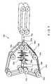
- FIG. 1shows schematically a perspective view of internal components of a machine suitable for the manufacture of air-filed cushions
- FIG. 2shows schematically a section view of the internal components of the machine during the manufacturing process
- FIG. 3shows schematically a section view of the internal components of the machine when opened to load or unload plastic tubing
- FIG. 4shows schematically a top view of the internal components of the machine during the manufacturing process
- FIG. 5shows schematically a portion of plastic tubing suitable for use in the machine
- FIG. 6shows schematically a rear view of the machine
- FIG. 7shows schematically a second embodiment of the invention, having a more compact structure.
- FIG. 1An exemplary embodiment of the system in accordance with the invention is shown in FIG. 1 and is designated generally by reference character 10 .
- FIG. 1The internal components of a machine for the manufacture of gas-filled (preferably air-filled) cushions is illustrated in FIG. 1 .
- the machine 10comprises an air barrier 11 , an injector 12 , heat sealers 14 , and pull rollers or drive rollers 16 , which incorporate a perforator 18 . These components of the machine 10 define a path along which tubular film passes through the machine 10 .
- a variety of materialscan be used for the film material. Most preferably, a plastic material of varying weights of polyethylene can be used. However, other types of plastic films can be used as desired, including metallized plastic films and the like. Moreover, other materials such as paper based films can also be used that are sealed with adhesive material, or paper films having a thin polyethylene coating to facilitate sealing can also be used.
- the air barrier 11is disposed upstream of the injector 12 and includes two tracked belts. These belts are preferably made from spongy, rubberized tracking material.
- the injector 12comprises an elongate hollow tube having an air inlet 20 and a plurality of outlets 22 . At its upstream end it has a smooth rounded tip 24 .
- the outlets 22are disposed close to the tip 24 and comprise a pair of elongate slits which are disposed diametrically opposite from each other on the circumference of the injector 12 .
- heat sealers 14are disposed downstream of the injector, adjacent to the outlets. Since heat sealers 14 are identical, only one heat sealer will be described. As depicted herein, for purposes of illustration and not limitation, heat sealer 14 includes two belts 40 , each belt 40 arranged around four wheels: a drive wheel 42 , a tensioner wheel 44 and two idler wheels 46 , 48 . The two belts 40 run parallel and adjacent to each other between the idler wheels 46 , 48 and between them define a path through which the plastic tubing is drawn.
- the inlet 20is a hollow tube, which is disposed downstream of the sealing rollers. Inlet 20 projects downwardly from the injector 12 .
- a cutterpreferably a knife 30 , is disposed at the upstream end of the inlet 20 , and projects diagonally between the inlet 20 and the injector 12 . It should be noted that a hot wire could be used instead of or in addition to a cutter.
- the inlet 20also supports the machine 10 , being attached to a superstructure (not shown) which holds the injector 12 in a fixed position in use. Various of the rollers and drive band wheels are also supported, being attached to the side of the machine by axles 60 , 62 , as shown in FIG. 4 .
- the pull rollers 16are arranged just downstream of the inlet 20 and the injector 12 .
- the perforator 18is arranged along the centerline of the machine 10 , to perforate between the seals produced by the heat sealers 14 .
- FIG. 2illustrates the machine 10 in use, with polythene tubing being drawn through it.
- FIG. 4provides a top view of the air cushion production process.
- a tube 32 of polythene film, typically 400 mm wide,is provided.
- the tube 32 of filmcan be provided on a roll mounted on an unwind shaft as depicted, or can be supplied in fan-folded form in a box, as desired.
- a support cradlecan alternatively be used as depicted in WO 01/21391.
- Such a cradlecan be advantageous in that a roll of film 32 can be placed thereon with a minimum of effort.
- Using a cantilevered unwind shaftcan be disadvantageous to the extent that the roll of film 32 has to be further manipulated to fit it over the shaft.
- Merely requiring the roll to be placed on top of two rollers in a cradle arrangementminimizes the need to maneuver the roll, thereby minimizing the time required for an operator to hold the roll of film 32 . This results in a time savings, and, more importantly, reduces the chances for operator injury (particularly back strains) as rolls of film 32 can be quite heavy if they are large.
- the tubingshown in FIG. 5 , has two rows of transverse, parallel welds or seals, 34 , 35 .
- the tube 32can also be pre-perforated across its width, along the line of the transverse seals 34 , 35 .
- the rows of seals 34 , 35extend toward a longitudinal centerline of the tubing 32 from a respective one of the side edges, a weld of one row 34 being generally co-linear with a weld of the other row 35 , and the rows of welds having an unwelded portion between them.
- score linescan additionally or alternatively be used to separate cushions from one another. Score lines can present the additional advantage that air leakage is minimized during inflation. Moreover, not having perforations across the inflation channel of the roll of film 32 can prevent the film from getting caught on the inflation tube, as it is known that perforations can cause such problems, thereby requiring the machine to be shut off, thereby reducing efficiency. Score lines can be formed on the roll of film 32 by mechanical deformation. More preferably, the score lines can be formed by way of laser scoring. Laser scoring is advantageous in that it permits precise control of the depth of the score line, permitting unprecedented flexibility and control on the amount of force needed to separate air filled cushions from one another.
- the air barrier 11is lifted apart, as shown in FIG. 3 , and the injector 12 is inserted into the tubing at the unwelded portion between the rows of the transverse seals 34 , 35 .
- the upper halves of the heat sealers 14can be pivoted into a standby position, as shown in FIG. 3 so that the plastic tubing 32 can be drawn over the injector 12 and positioned between the pull rollers 16 .
- the polythene tubing 32is drawn through the machine 10 by the tracks which make up the air barrier 11 , by the belts 40 of the heat sealers 14 and by the pull rollers 16 .
- the pull rollers 16operate marginally more quickly than the rest of the machine which places the tubing 32 under tension, even to the extent where some slippage through the rest of the machine can occur.
- the tubing 32is continually drawn from the roll of film 32 through the air barrier 11 by its tracks.
- the two layers of the tubing 32are separated in its central, unwelded portion on reaching the smooth, rounded tip 24 of the injector 12 .
- the presence of the air barrier 11prevents excess upstream inflation.
- the portions of the tubing defined by adjacent welds 34 , 35 in each rowbecome inflated, as shown in FIG. 2 .
- the injector 12is disposed centrally in the tubing, with outlets 22 directed to either side, two portions, one at either side of the injector 12 are inflated as the tubing 32 is drawn over the outlets 22 .
- To encapsulate the air in each portionthe open side of each portion is sealed by heat sealers 14 . These produce two longitudinal welds 36 which each join a pair of transverse welds 34 , 35 , sealing off the inflated air cushions.
- the downstream sealing blocks 54 , 56compress the tubing over the longitudinal weld 36 , making it more secure.
- the tubing 32must pass the inlet 20 of the injector member. To allow the tubing to pass around this inlet 20 the lower face of the tubing 32 is slit as it passes the knife 30 disposed just upstream of the inlet.
- the pull rollers 16draw the tubing toward the perforator 18 .
- the perforator 18produces a row of perforations 38 in the centre of the bottom face of the tubing, between the longitudinal welds. These perforations allow the tubing to be separated longitudinally if desired.
- roll of film 32can be provided with perforations pre-formed therein.
- Finished cushions 64 , supported by a cushion bed plate 66are shown in FIG. 6 , just before they leave the machine.
- This machine 10has a much higher output rate than previous machines, both because it is able to run continually, and because it can produce two streams of air cushions at once. Since the air can be injected through relatively large outlets 22 there is no need for compressed air to be used.
- the machine, 10is, therefore, simple to use, having just an on-off and a temperature control. Further controls, such as a speed control and an inflation control could be added to the system if desired.
- the machine 10is able to produce air cushions which are joined together to form a matrix of cells. Since these cells are more difficult to force apart they are more effective at protecting packages with irregular shapes. Furthermore, since the machine 10 can inflate multiple cushions through one central tube it uses the plastic tubing more efficiently than previous machines and generates less waste.
- a top half of the heat sealer 14is defined by the upper belt 40 , its four wheels 42 , 44 , 46 and includes the upper heated sealing block 50 and the other upper sealing block 54 .
- This half of the heat sealeris pivotally mounted along the axis of drive wheel 42 so that it can be swung away from its operative position, in which the portion of the belt between the idler wheels abuts the plastic tubing, to a standby position in which the belt lies away from the plastic tubing.
- the top section of the heat sealer 14is pivoted back into its operating position and, since the heated sealing block 52 is still hot the sealing process can be immediately continued without losing any cushions.
- a second embodimentwill now be described only in as much as it differs from the first embodiment, the same reference numerals being used for the same parts.
- the machine 10 acan be made more compact, as shown in FIG. 7 .
- the injector 12 ahas been shortened in this embodiment so that the inlet 20 a projects downwards just downstream of the heat sealing blocks 50 a , 52 a , 54 a , 56 a .
- the pull rollers 16 aform the driving element for the heat sealer belts 40 a , the other wheels 42 a , 44 a , 46 a , being idler wheels.
- the perforator 18 ais thus arranged just downstream of the inlet 20 a .
- the perforator 18 ais arranged on the lower pull roller 16 a . Since the injector 12 a is significantly shorter in this arrangement even less pressure is required to cause air to flow to the outlets 22 a , making the machine 10 a even more efficient to run.
Landscapes
- Engineering & Computer Science (AREA)
- Mechanical Engineering (AREA)
- Manufacturing & Machinery (AREA)
- Buffer Packaging (AREA)
- Containers And Plastic Fillers For Packaging (AREA)
- Lining Or Joining Of Plastics Or The Like (AREA)
Abstract
Description
Claims (18)
Priority Applications (3)
| Application Number | Priority Date | Filing Date | Title |
|---|---|---|---|
| US12/546,472US8430147B2 (en) | 2004-07-20 | 2009-08-24 | Machine and methods for the manufacture of air-filled cushions |
| US13/872,625US8905110B2 (en) | 2004-07-20 | 2013-04-29 | Machine and methods for the manufacture of air-filled cushions |
| US14/564,046US9242748B2 (en) | 2004-07-20 | 2014-12-08 | Machine and methods for the manufacture of air-filled cushions |
Applications Claiming Priority (3)
| Application Number | Priority Date | Filing Date | Title |
|---|---|---|---|
| US58974804P | 2004-07-20 | 2004-07-20 | |
| US11/185,927US7578333B2 (en) | 2004-07-20 | 2005-07-19 | Machine and methods for the manufacture of air-filled cushions |
| US12/546,472US8430147B2 (en) | 2004-07-20 | 2009-08-24 | Machine and methods for the manufacture of air-filled cushions |
Related Parent Applications (1)
| Application Number | Title | Priority Date | Filing Date |
|---|---|---|---|
| US11/185,927ContinuationUS7578333B2 (en) | 2004-07-20 | 2005-07-19 | Machine and methods for the manufacture of air-filled cushions |
Related Child Applications (1)
| Application Number | Title | Priority Date | Filing Date |
|---|---|---|---|
| US13/872,625ContinuationUS8905110B2 (en) | 2004-07-20 | 2013-04-29 | Machine and methods for the manufacture of air-filled cushions |
Publications (2)
| Publication Number | Publication Date |
|---|---|
| US20100051202A1 US20100051202A1 (en) | 2010-03-04 |
| US8430147B2true US8430147B2 (en) | 2013-04-30 |
Family
ID=37567786
Family Applications (4)
| Application Number | Title | Priority Date | Filing Date |
|---|---|---|---|
| US11/185,927Active2026-07-04US7578333B2 (en) | 2004-07-20 | 2005-07-19 | Machine and methods for the manufacture of air-filled cushions |
| US12/546,472Active2027-10-10US8430147B2 (en) | 2004-07-20 | 2009-08-24 | Machine and methods for the manufacture of air-filled cushions |
| US13/872,625Expired - LifetimeUS8905110B2 (en) | 2004-07-20 | 2013-04-29 | Machine and methods for the manufacture of air-filled cushions |
| US14/564,046Expired - LifetimeUS9242748B2 (en) | 2004-07-20 | 2014-12-08 | Machine and methods for the manufacture of air-filled cushions |
Family Applications Before (1)
| Application Number | Title | Priority Date | Filing Date |
|---|---|---|---|
| US11/185,927Active2026-07-04US7578333B2 (en) | 2004-07-20 | 2005-07-19 | Machine and methods for the manufacture of air-filled cushions |
Family Applications After (2)
| Application Number | Title | Priority Date | Filing Date |
|---|---|---|---|
| US13/872,625Expired - LifetimeUS8905110B2 (en) | 2004-07-20 | 2013-04-29 | Machine and methods for the manufacture of air-filled cushions |
| US14/564,046Expired - LifetimeUS9242748B2 (en) | 2004-07-20 | 2014-12-08 | Machine and methods for the manufacture of air-filled cushions |
Country Status (1)
| Country | Link |
|---|---|
| US (4) | US7578333B2 (en) |
Cited By (2)
| Publication number | Priority date | Publication date | Assignee | Title |
|---|---|---|---|---|
| US8905110B2 (en)* | 2004-07-20 | 2014-12-09 | Pregis Innovative Packaging, Inc. | Machine and methods for the manufacture of air-filled cushions |
| US9718155B2 (en) | 2014-01-20 | 2017-08-01 | Turbotec Products, Inc. | Insulated heat exchanger tube assembly and methods of making and using same |
Families Citing this family (28)
| Publication number | Priority date | Publication date | Assignee | Title |
|---|---|---|---|---|
| EP1254049B1 (en) | 2000-01-20 | 2011-05-11 | Free-Flow Packaging International, Inc. | Apparatus for making pneumatically filled packing cushions |
| US7897219B2 (en) | 2004-06-01 | 2011-03-01 | Automated Packaging Systems, Inc. | Web and method for making fluid filled units |
| EP3150369B1 (en) | 2004-06-01 | 2020-03-18 | Automated Packaging Systems, Inc. | Web for making fluid filled units |
| ES2604877T3 (en)* | 2006-09-20 | 2017-03-09 | Pregis Innovative Packaging Inc. | Inflation and sealing device for inflatable air pads |
| US8061110B2 (en)* | 2007-10-12 | 2011-11-22 | Pregis Innovative Packaging, Inc. | Inflation and sealing device with disengagement mechanism |
| CA2700223C (en) | 2007-10-31 | 2017-05-09 | Automated Packaging Systems, Inc. | Web and method for making fluid filled units |
| US8567653B2 (en) | 2008-05-15 | 2013-10-29 | Pregis Innovative Packaging, Inc. | Automated air pillow dispenser |
| US9067378B2 (en)* | 2008-07-01 | 2015-06-30 | Pregis Innovative Packaging Inc. | Inflation and sealing device with rotary cutter |
| US9381715B2 (en) | 2008-09-03 | 2016-07-05 | Free-Flow Packaging International, Inc. | Method and apparatus for inflating and sealing packing cushions with rotary sealing mechanism |
| WO2010028115A1 (en)* | 2008-09-03 | 2010-03-11 | Free-Flow Packaging International, Inc. | Method and apparatus for inflating and sealing packing cushions with rotary sealing mechanism |
| US9205622B2 (en) | 2009-02-27 | 2015-12-08 | Automated Packaging Systems, Inc. | Web and method for making fluid filled units |
| WO2011085116A2 (en)* | 2010-01-06 | 2011-07-14 | Pregis Innovative Packaging, Inc. | Packaging pillow device with upstream components |
| US8375681B2 (en)* | 2010-02-10 | 2013-02-19 | Indis Air Corp. | Air injection apparatus for buffer packing bag and air injection method using the same |
| US9623622B2 (en) | 2010-02-24 | 2017-04-18 | Michael Baines | Packaging materials and methods |
| CH703963A2 (en)* | 2010-10-25 | 2012-04-30 | Guy Borgeat | Machine inflation automatic filling gas cushion, in particular air, for packaging, and its use to inflate and fill the bags. |
| PL2729369T3 (en) | 2011-07-07 | 2017-07-31 | Automated Packaging Systems, Inc. | Air cushion inflation machine |
| ITPI20110129A1 (en)* | 2011-11-16 | 2013-05-17 | Fill Teck S R L | PERFECT MACHINE FOR THE PRODUCTION OF MATERIAL FOR PACKAGING IN THE FORM OF AIR CUSHIONS, OR OTHER GAS, AND RELATED PRODUCTION METHOD |
| KR20150130271A (en) | 2013-03-15 | 2015-11-23 | 오토메이티드 패키징 시스템즈, 인코포레이티드 | On-demand inflatable packaging |
| CA2931243A1 (en) | 2013-11-21 | 2015-05-28 | Automated Packaging Systems, Inc. | Air cushion inflation machine |
| US20150151864A1 (en)* | 2013-12-02 | 2015-06-04 | Stan Lin | Air Packaging Machine |
| WO2015118450A1 (en)* | 2014-02-06 | 2015-08-13 | I.M.A. Industria Macchine Automatiche S.P.A. | Unit and method for releasing product for extraction or infusion beverages in containers forming single-use capsules or pods |
| KR101551561B1 (en)* | 2014-02-10 | 2015-09-08 | 변상헌 | Fill-Air Packing Machine |
| US10328653B2 (en) | 2014-02-24 | 2019-06-25 | Pregis Innovative Packaging Llc | Inflation and sealing device with inclined components |
| NL2012357B1 (en)* | 2014-03-04 | 2015-12-03 | Ideepak Holding Bv | Sealing unit, sealing apparatus, method for manufacturing air or gas filled bags, and air or gas filled bag. |
| CN106863981B (en)* | 2017-01-16 | 2019-01-11 | 伯恩太阳能科技有限公司 | A kind of heat device with film hot synthetic type device |
| MX2020008495A (en)* | 2018-02-14 | 2021-10-13 | Pregis Innovative Packaging Llc | Devices for manufacturing inflatable chushions to be used as packaging material. |
| US11220082B2 (en)* | 2019-08-21 | 2022-01-11 | Michael G Kaminski | Method for inflating airbags |
| US12043435B1 (en)* | 2021-09-22 | 2024-07-23 | Michael G Kaminski | Packing machine for inflatable bags |
Citations (15)
| Publication number | Priority date | Publication date | Assignee | Title |
|---|---|---|---|---|
| US3366523A (en) | 1963-12-20 | 1968-01-30 | Weber Hans | Method and apparatus for continuously forming fluid-filled padding from thermoplastic webs |
| US3667593A (en) | 1970-03-30 | 1972-06-06 | John M Pendleton | Flowable dunnage apparatus and method of packaging with flowable and compliable inflated dunnage material |
| US3817803A (en) | 1972-06-19 | 1974-06-18 | Fmc Corp | Method of making a cellular cushioning structure |
| US3868285A (en) | 1973-07-18 | 1975-02-25 | Constantine T Troy | Methods and apparatus for the manufacture of cellular cushioning materials |
| US4017351A (en) | 1975-12-24 | 1977-04-12 | Minnesota Mining And Manufacturing Company | System and device for inflating and sealing air inflated cushioning material |
| US4049854A (en) | 1974-05-20 | 1977-09-20 | Minnesota Mining And Manufacturing Company | System for inflation and sealing of air cushions |
| US5824392A (en) | 1994-03-24 | 1998-10-20 | Idemitsu Petrochemical Co., Ltd. | Method of producing an air cushion and an apparatus for the same |
| WO2001021391A1 (en) | 1999-09-22 | 2001-03-29 | Ambassador Packaging Limited | Method and machine for the manufacture of air pillows |
| US6209286B1 (en) | 1999-03-09 | 2001-04-03 | Novus Packaging Corporation | Machine and method for manufacturing a continuous production of pneumatically filled inflatable packaging pillows |
| US6410119B1 (en) | 2000-11-21 | 2002-06-25 | Free-Flow Packaging International, Inc. | Inflatable, cushioning, bubble wrap product having multiple, interconnected, bubble structures |
| US6582800B2 (en) | 2000-01-20 | 2003-06-24 | Free-Flow Packaging International, Inc. | Method for making pneumatically filled packing cushions |
| US20030163976A1 (en) | 2002-03-01 | 2003-09-04 | Andrew Perkins | Machine and method for inflating and sealing air-filled packing cushions |
| US6659150B1 (en) | 2000-08-14 | 2003-12-09 | Free-Flow Packaging International, Inc. | Apparatus for inflating and sealing air-filled packing cushions |
| US20040154728A1 (en) | 2003-02-07 | 2004-08-12 | Selle Paul A. | Devices and methods for manufacturing packaging materials |
| US6889739B2 (en) | 2003-04-08 | 2005-05-10 | Automated Packaging Systems, Inc. | Fluid filled unit formation machine and process |
Family Cites Families (29)
| Publication number | Priority date | Publication date | Assignee | Title |
|---|---|---|---|---|
| US3690426A (en)* | 1971-08-27 | 1972-09-12 | Gen Motors Corp | Wheel lock control differential |
| JPS585338B2 (en)* | 1975-04-14 | 1983-01-31 | 株式会社小松製作所 | Kutsusakutsumikomishiyariyou |
| JPS5251631A (en)* | 1975-10-22 | 1977-04-25 | Nissan Motor Co Ltd | Hydraulic control device for transmission of industrial vehicle |
| DE2658195C2 (en)* | 1976-12-22 | 1978-12-14 | Zahnradfabrik Friedrichshafen Ag, 7990 Friedrichshafen | Pressure medium circuit for a hydrodynamic-mechanical compound transmission |
| US4111287A (en)* | 1977-01-28 | 1978-09-05 | Caterpillar Tractor Co. | Shift modulating control accumulator |
| US6578692B2 (en)* | 2001-03-27 | 2003-06-17 | New Venture Gear, Inc. | Rear drive module for all-wheel drive vehicle |
| US4284182A (en)* | 1978-02-09 | 1981-08-18 | Caterpillar Tractor Co. | Vehicle steering brake and clutch control |
| US4512894A (en)* | 1982-12-17 | 1985-04-23 | Celanese Corporation | Process for the production of semipermeable polybenzimidazole membranes and the resultant product |
| DE3418520A1 (en)* | 1984-05-18 | 1985-11-21 | Teves Gmbh Alfred | SLIP-CONTROLLED BRAKE SYSTEM FOR ROAD VEHICLES WITH ALL-WHEEL DRIVE |
| US4991679A (en)* | 1985-06-21 | 1991-02-12 | Honda Giken Kogyo Kabushiki Kaisha | Four wheel-drive anti-locking braking |
| DE3527532A1 (en)* | 1985-08-01 | 1987-02-12 | Teves Gmbh Alfred | METHOD AND BRAKE SYSTEM FOR DRIVE CONTROL |
| JPH0448349Y2 (en)* | 1987-04-20 | 1992-11-13 | ||
| JP2709927B2 (en)* | 1987-11-24 | 1998-02-04 | 富士重工業株式会社 | Brake hydraulic pressure control method for hydraulic brake system for automobile |
| US5622837A (en)* | 1990-07-28 | 1997-04-22 | Schebo Tech Medizinisch-Biologische Forschungsgesellschaft Mbh | Pancreas elastase 1-specific antibody, a process for obtaining it, and a test kit containing such antibody |
| EP0736409B1 (en)* | 1991-10-08 | 2000-03-15 | Mitsubishi Jidosha Kogyo Kabushiki Kaisha | Torque adjusting apparatus |
| DE19504847B4 (en)* | 1994-02-23 | 2006-04-27 | Luk Gs Verwaltungs Kg | Monitoring method for a torque transmission system of a motor vehicle |
| US5562192A (en)* | 1994-11-01 | 1996-10-08 | Dana Corporation | Electronic clutch control mechanism for a vehicle transmission |
| DE19706720A1 (en)* | 1996-04-06 | 1997-10-09 | Volkswagen Ag | Controlling coupling between front and rear axles of motor vehicle with four wheel drive |
| US5688202A (en)* | 1996-07-09 | 1997-11-18 | New Venture Gear, Inc. | Powershift transfer case |
| US5818678A (en)* | 1997-10-09 | 1998-10-06 | Delco Electronics Corporation | Tri-state control apparatus for a solenoid having on off and PWM control modes |
| AUPP565098A0 (en)* | 1998-09-03 | 1998-09-24 | Hbp Permo-Drive Pty Ltd | Energy management system |
| US6418714B1 (en)* | 1999-10-22 | 2002-07-16 | Honeywell International, Inc. | Accumulator utilizing housing case pressure |
| SE515747C2 (en)* | 1999-12-13 | 2001-10-01 | Volvo Lastvagnar Ab | Hydraulic control system for a vehicle transmission |
| DE10018630A1 (en)* | 2000-04-14 | 2001-10-25 | Mannesmann Sachs Ag | Actuator for a motor vehicle friction clutch |
| DE10018649A1 (en)* | 2000-04-14 | 2001-10-25 | Mannesmann Sachs Ag | Actuator for frictional coupling has control/regulating valve for controling cylinder device depending on actual/desired disengagement, control electronics with various characteristics |
| US6619457B2 (en)* | 2001-05-11 | 2003-09-16 | Midwest Brake Bond Company | Bi-directional clutch unit |
| JP4294286B2 (en)* | 2002-09-24 | 2009-07-08 | 富士重工業株式会社 | Vehicle differential limiting control device |
| US7007782B2 (en)* | 2003-02-14 | 2006-03-07 | Automotive Components Holdings Llc | Control of a hydraulic coupling system |
| US7578333B2 (en)* | 2004-07-20 | 2009-08-25 | Pregis Corporation | Machine and methods for the manufacture of air-filled cushions |
- 2005
- 2005-07-19USUS11/185,927patent/US7578333B2/enactiveActive
- 2009
- 2009-08-24USUS12/546,472patent/US8430147B2/enactiveActive
- 2013
- 2013-04-29USUS13/872,625patent/US8905110B2/ennot_activeExpired - Lifetime
- 2014
- 2014-12-08USUS14/564,046patent/US9242748B2/ennot_activeExpired - Lifetime
Patent Citations (15)
| Publication number | Priority date | Publication date | Assignee | Title |
|---|---|---|---|---|
| US3366523A (en) | 1963-12-20 | 1968-01-30 | Weber Hans | Method and apparatus for continuously forming fluid-filled padding from thermoplastic webs |
| US3667593A (en) | 1970-03-30 | 1972-06-06 | John M Pendleton | Flowable dunnage apparatus and method of packaging with flowable and compliable inflated dunnage material |
| US3817803A (en) | 1972-06-19 | 1974-06-18 | Fmc Corp | Method of making a cellular cushioning structure |
| US3868285A (en) | 1973-07-18 | 1975-02-25 | Constantine T Troy | Methods and apparatus for the manufacture of cellular cushioning materials |
| US4049854A (en) | 1974-05-20 | 1977-09-20 | Minnesota Mining And Manufacturing Company | System for inflation and sealing of air cushions |
| US4017351A (en) | 1975-12-24 | 1977-04-12 | Minnesota Mining And Manufacturing Company | System and device for inflating and sealing air inflated cushioning material |
| US5824392A (en) | 1994-03-24 | 1998-10-20 | Idemitsu Petrochemical Co., Ltd. | Method of producing an air cushion and an apparatus for the same |
| US6209286B1 (en) | 1999-03-09 | 2001-04-03 | Novus Packaging Corporation | Machine and method for manufacturing a continuous production of pneumatically filled inflatable packaging pillows |
| WO2001021391A1 (en) | 1999-09-22 | 2001-03-29 | Ambassador Packaging Limited | Method and machine for the manufacture of air pillows |
| US6582800B2 (en) | 2000-01-20 | 2003-06-24 | Free-Flow Packaging International, Inc. | Method for making pneumatically filled packing cushions |
| US6659150B1 (en) | 2000-08-14 | 2003-12-09 | Free-Flow Packaging International, Inc. | Apparatus for inflating and sealing air-filled packing cushions |
| US6410119B1 (en) | 2000-11-21 | 2002-06-25 | Free-Flow Packaging International, Inc. | Inflatable, cushioning, bubble wrap product having multiple, interconnected, bubble structures |
| US20030163976A1 (en) | 2002-03-01 | 2003-09-04 | Andrew Perkins | Machine and method for inflating and sealing air-filled packing cushions |
| US20040154728A1 (en) | 2003-02-07 | 2004-08-12 | Selle Paul A. | Devices and methods for manufacturing packaging materials |
| US6889739B2 (en) | 2003-04-08 | 2005-05-10 | Automated Packaging Systems, Inc. | Fluid filled unit formation machine and process |
Cited By (3)
| Publication number | Priority date | Publication date | Assignee | Title |
|---|---|---|---|---|
| US8905110B2 (en)* | 2004-07-20 | 2014-12-09 | Pregis Innovative Packaging, Inc. | Machine and methods for the manufacture of air-filled cushions |
| US9242748B2 (en)* | 2004-07-20 | 2016-01-26 | Pregis Innovative Packaging Llc | Machine and methods for the manufacture of air-filled cushions |
| US9718155B2 (en) | 2014-01-20 | 2017-08-01 | Turbotec Products, Inc. | Insulated heat exchanger tube assembly and methods of making and using same |
Also Published As
| Publication number | Publication date |
|---|---|
| US20060292320A1 (en) | 2006-12-28 |
| US20100051202A1 (en) | 2010-03-04 |
| US20150158604A1 (en) | 2015-06-11 |
| US9242748B2 (en) | 2016-01-26 |
| US7578333B2 (en) | 2009-08-25 |
| US20130232913A1 (en) | 2013-09-12 |
| US8905110B2 (en) | 2014-12-09 |
Similar Documents
| Publication | Publication Date | Title |
|---|---|---|
| US8430147B2 (en) | Machine and methods for the manufacture of air-filled cushions | |
| US7721781B2 (en) | Apparatus and method for forming inflated chambers | |
| EP1254049B1 (en) | Apparatus for making pneumatically filled packing cushions | |
| US6209286B1 (en) | Machine and method for manufacturing a continuous production of pneumatically filled inflatable packaging pillows | |
| EP1817158B1 (en) | Apparatus and method for forming inflated containers | |
| US7845146B2 (en) | Method and apparatus for making dunnage | |
| EP2521648B1 (en) | Packaging pillow device with upstream components | |
| US7347911B2 (en) | Devices and methods for manufacturing packaging materials | |
| US6460313B1 (en) | Packaging filler product and machine for producing same | |
| EP2141007B1 (en) | Inflation and sealing device with rotary cutter | |
| US20050235600A1 (en) | Apparatus for inflating and sealing pillows in packaging cushions | |
| AU2002340921A1 (en) | Apparatus and method for forming inflated chambers | |
| GB2384459A (en) | Manufacture of air cushions from tubing with a gas injector continuously within the tubing | |
| JP2005518969A (en) | Machine and method for inflating and sealing a pneumatic packing cushion | |
| US6751926B1 (en) | Packaging filler product and machine for producing same | |
| US7913474B2 (en) | Apparatus for inflating tube film for manufacturing packaging material, and a method for inflating tube film with such apparatus | |
| WO2000043270A1 (en) | Machine for manufacturing pneumatically filled packing cushions | |
| US7503156B2 (en) | Method and apparatus for making dunnage | |
| HK1081925B (en) | Method and system for producing shock absorbing package containing packaged article | |
| HK1081925A1 (en) | Method and system for producing shock absorbing package containing packaged article |
Legal Events
| Date | Code | Title | Description |
|---|---|---|---|
| AS | Assignment | Owner name:WELLS FARGO CAPITAL FINANCE, LLC, AS AGENT, CALIFO Free format text:PATENT SECURITY AGREEMENT;ASSIGNORS:PREGIS HOLDING II CORPORATION;PREGIS CORPORATION;PREGIS INNOVATIVE PACKAGING INC.;AND OTHERS;REEL/FRAME:026010/0305 Effective date:20110323 | |
| AS | Assignment | Owner name:PREGIS CORPORATION, ILLINOIS Free format text:ASSIGNMENT OF ASSIGNORS INTEREST;ASSIGNORS:GREENWOOD, JOHN STUART;PRICE, NEIL GLYNN;SIGNING DATES FROM 20051206 TO 20051209;REEL/FRAME:027859/0739 | |
| AS | Assignment | Owner name:PREGIS HOLDING II CORPORATION, ILLINOIS Free format text:RELEASE BY SECURED PARTY;ASSIGNOR:WELLS FARGO CAPITAL FINANCE, LLC;REEL/FRAME:027930/0392 Effective date:20120323 Owner name:PREGIS CORPORATION, ILLINOIS Free format text:RELEASE BY SECURED PARTY;ASSIGNOR:WELLS FARGO CAPITAL FINANCE, LLC;REEL/FRAME:027930/0392 Effective date:20120323 Owner name:GENERAL ELECTRIC CAPITAL CORPORATION, AS ADMINISTR Free format text:SECURITY AGREEMENT;ASSIGNOR:PREGIS CORPORATION;REEL/FRAME:027924/0775 Effective date:20120323 Owner name:PREGIS INTELLIPACK CORP., OKLAHOMA Free format text:RELEASE BY SECURED PARTY;ASSIGNOR:WELLS FARGO CAPITAL FINANCE, LLC;REEL/FRAME:027930/0392 Effective date:20120323 Owner name:PREGIS INNOVATIVE PACKAGING INC., ILLINOIS Free format text:RELEASE BY SECURED PARTY;ASSIGNOR:WELLS FARGO CAPITAL FINANCE, LLC;REEL/FRAME:027930/0392 Effective date:20120323 | |
| AS | Assignment | Owner name:PREGIS INTELLIPACK CORP., OKLAHOMA Free format text:RELEASE BY SECURED PARTY;ASSIGNOR:WELLS FARGO CAPITAL FINANCE, LLC;REEL/FRAME:027933/0197 Effective date:20120323 Owner name:PREGIS HOLDING II CORPORATION, ILLINOIS Free format text:RELEASE BY SECURED PARTY;ASSIGNOR:WELLS FARGO CAPITAL FINANCE, LLC;REEL/FRAME:027933/0197 Effective date:20120323 Owner name:PREGIS CORPORATION, ILLINOIS Free format text:RELEASE BY SECURED PARTY;ASSIGNOR:WELLS FARGO CAPITAL FINANCE, LLC;REEL/FRAME:027933/0197 Effective date:20120323 Owner name:PREGIS INNOVATIVE PACKAGING INC., ILLINOIS Free format text:RELEASE BY SECURED PARTY;ASSIGNOR:WELLS FARGO CAPITAL FINANCE, LLC;REEL/FRAME:027933/0197 Effective date:20120323 | |
| AS | Assignment | Owner name:PREGIS INNOVATIVE PACKAGING, INC., ILLINOIS Free format text:ASSIGNMENT OF ASSIGNORS INTEREST;ASSIGNOR:PREGIS CORPORATION;REEL/FRAME:028927/0907 Effective date:20120830 | |
| STCF | Information on status: patent grant | Free format text:PATENTED CASE | |
| AS | Assignment | Owner name:GENERAL ELECTRIC CAPITAL CORPORATION, AS ADMINISTR Free format text:SECURITY AGREEMENT;ASSIGNOR:PREGIS INNOVATIVE PACKAGING INC.;REEL/FRAME:030389/0030 Effective date:20130509 | |
| AS | Assignment | Owner name:BARCLAYS BANK PLC, AS COLLATERAL AGENT, NEW YORK Free format text:SECURITY INTEREST;ASSIGNORS:PREGIS ULTIMATE HOLDINGS CORPORATION;PREGIS HOLDING I CORPORATION;PREGIS HOLDING II CORPORATION;AND OTHERS;REEL/FRAME:032972/0325 Effective date:20140520 Owner name:PREGIS CORPORATION, ILLINOIS Free format text:RELEASE OF SECURITY INTEREST;ASSIGNOR:GENERAL ELECTRIC CAPITAL CORPORATION;REEL/FRAME:032971/0813 Effective date:20140520 Owner name:PREGIS INNOVATIVE PACKAGING INC., ILLINOIS Free format text:RELEASE OF SECURITY INTEREST;ASSIGNOR:GENERAL ELECTRIC CAPITAL CORPORATION;REEL/FRAME:032971/0292 Effective date:20140520 Owner name:PREGIS CORPORATION, ILLINOIS Free format text:RELEASE OF SECURITY INTEREST;ASSIGNOR:WELLS FARGO BANK, NATIONAL ASSOCIATION;REEL/FRAME:032971/0821 Effective date:20140520 | |
| AS | Assignment | Owner name:U.S. BANK NATIONAL ASSOCIATION, NORTH CAROLINA Free format text:SECURITY INTEREST;ASSIGNORS:PREGIS CORPORATION;PREGIS INNOVATIVE PACKAGING INC.;PREGIS INTELLIPACK CORP.;REEL/FRAME:032998/0417 Effective date:20140520 | |
| AS | Assignment | Owner name:PREGIS INNOVATIVE PACKAGING LLC, ILLINOIS Free format text:CHANGE OF NAME;ASSIGNOR:PREGIS INNOVATIVE PACKAGING INC.;REEL/FRAME:035801/0338 Effective date:20141230 | |
| FPAY | Fee payment | Year of fee payment:4 | |
| AS | Assignment | Owner name:PREGIS INTELLIPACK LLC (F/K/A PREGIS INTELLIPACK C Free format text:RELEASE BY SECURED PARTY;ASSIGNOR:U.S. BANK NATIONAL ASSOCIATION;REEL/FRAME:042586/0596 Effective date:20170524 Owner name:PREGIS LLC (F/K/A PREGIS CORPORATION), ILLINOIS Free format text:RELEASE BY SECURED PARTY;ASSIGNOR:U.S. BANK NATIONAL ASSOCIATION;REEL/FRAME:042586/0596 Effective date:20170524 Owner name:PREGIS INNOVATIVE PACKAGING, LLC (F/K/A PREGIS INN Free format text:RELEASE BY SECURED PARTY;ASSIGNOR:U.S. BANK NATIONAL ASSOCIATION;REEL/FRAME:042586/0596 Effective date:20170524 Owner name:PREGIS INTELLIPACK LLC (F/K/A PREGIS INTELLIPACK CORP.), OKLAHOMA Free format text:RELEASE BY SECURED PARTY;ASSIGNOR:U.S. BANK NATIONAL ASSOCIATION;REEL/FRAME:042586/0596 Effective date:20170524 Owner name:PREGIS INNOVATIVE PACKAGING, LLC (F/K/A PREGIS INNOVATIVE PACKAGING INC.), ILLINOIS Free format text:RELEASE BY SECURED PARTY;ASSIGNOR:U.S. BANK NATIONAL ASSOCIATION;REEL/FRAME:042586/0596 Effective date:20170524 | |
| AS | Assignment | Owner name:OWL ROCK CAPITAL CORPORATION, AS COLLATERAL AGENT, NEW YORK Free format text:SECURITY INTEREST;ASSIGNORS:PREGIS INNOVATIVE PACKAGING INC.;PREGIS INTELLIPACK LLC;PREGIS SHARP SYSTEMS, LLC;AND OTHERS;REEL/FRAME:046593/0535 Effective date:20180713 Owner name:OWL ROCK CAPITAL CORPORATION, AS COLLATERAL AGENT, Free format text:SECURITY INTEREST;ASSIGNORS:PREGIS INNOVATIVE PACKAGING INC.;PREGIS INTELLIPACK LLC;PREGIS SHARP SYSTEMS, LLC;AND OTHERS;REEL/FRAME:046593/0535 Effective date:20180713 | |
| AS | Assignment | Owner name:CREDIT SUISSE AG, CAYMAN ISLANDS BRANCH, NEW YORK Free format text:FIRST LIEN SECURITY AGREEMENT;ASSIGNOR:PREGIS INNOVATIVE PACKAGING LLC;REEL/FRAME:049932/0377 Effective date:20190801 Owner name:PREGIS CORPORATION, ILLINOIS Free format text:RELEASE OF SECURITY INTEREST IN PATENTS;ASSIGNOR:BARCLAYS BANK PLC;REEL/FRAME:049941/0690 Effective date:20190801 Owner name:PREGIS HOLDING I CORPORATION, ILLINOIS Free format text:RELEASE OF SECURITY INTEREST IN PATENTS;ASSIGNOR:BARCLAYS BANK PLC;REEL/FRAME:049941/0690 Effective date:20190801 Owner name:PREGIS ULTIMATE HOLDINGS CORPORATION, ILLINOIS Free format text:RELEASE OF SECURITY INTEREST IN PATENTS;ASSIGNOR:BARCLAYS BANK PLC;REEL/FRAME:049941/0690 Effective date:20190801 Owner name:PREGIS INTELLIPACK CORP., ILLINOIS Free format text:RELEASE OF SECURITY INTEREST IN PATENTS;ASSIGNOR:BARCLAYS BANK PLC;REEL/FRAME:049941/0690 Effective date:20190801 Owner name:SURFACE GUARD, INC., ILLINOIS Free format text:RELEASE OF SECURITY INTEREST IN PATENTS;ASSIGNOR:BARCLAYS BANK PLC;REEL/FRAME:049941/0690 Effective date:20190801 Owner name:OWL ROCK CAPITAL CORPORATION, AS SECOND LIEN COLLA Free format text:SECOND LIEN PATENT SECURITY AGREEMENT;ASSIGNOR:PREGIS INNOVATIVE PACKAGING LLC;REEL/FRAME:049941/0652 Effective date:20190801 Owner name:SINGLE FACE SUPPLY CO., ILLINOIS Free format text:RELEASE OF SECURITY INTEREST IN PATENTS;ASSIGNOR:BARCLAYS BANK PLC;REEL/FRAME:049941/0690 Effective date:20190801 Owner name:PREGIS INNOVATIVE PACKAGING INC., ILLINOIS Free format text:RELEASE OF SECURITY INTEREST IN PATENTS;ASSIGNOR:BARCLAYS BANK PLC;REEL/FRAME:049941/0690 Effective date:20190801 Owner name:PREGIS HOLDING II CORPORATION, ILLINOIS Free format text:RELEASE OF SECURITY INTEREST IN PATENTS;ASSIGNOR:BARCLAYS BANK PLC;REEL/FRAME:049941/0690 Effective date:20190801 Owner name:OWL ROCK CAPITAL CORPORATION, AS SECOND LIEN COLLATERAL AGENT, NEW YORK Free format text:SECOND LIEN PATENT SECURITY AGREEMENT;ASSIGNOR:PREGIS INNOVATIVE PACKAGING LLC;REEL/FRAME:049941/0652 Effective date:20190801 | |
| AS | Assignment | Owner name:PREGIS INTELLIPACK LLC, ILLINOIS Free format text:RELEASE BY SECURED PARTY;ASSIGNOR:OWL ROCK CAPITAL CORPORATION, AS COLLATERAL AGENT;REEL/FRAME:050993/0798 Effective date:20190801 Owner name:FREE-FLOW PACKAGING INTERNATIONAL, INC., ILLINOIS Free format text:RELEASE BY SECURED PARTY;ASSIGNOR:OWL ROCK CAPITAL CORPORATION, AS COLLATERAL AGENT;REEL/FRAME:050993/0798 Effective date:20190801 Owner name:PREGIS SHARP SYSTEMS, LLC, ILLINOIS Free format text:RELEASE BY SECURED PARTY;ASSIGNOR:OWL ROCK CAPITAL CORPORATION, AS COLLATERAL AGENT;REEL/FRAME:050993/0798 Effective date:20190801 Owner name:PREGIS INNOVATIVE PACKAGING INC., ILLINOIS Free format text:RELEASE BY SECURED PARTY;ASSIGNOR:OWL ROCK CAPITAL CORPORATION, AS COLLATERAL AGENT;REEL/FRAME:050993/0798 Effective date:20190801 | |
| MAFP | Maintenance fee payment | Free format text:PAYMENT OF MAINTENANCE FEE, 8TH YEAR, LARGE ENTITY (ORIGINAL EVENT CODE: M1552); ENTITY STATUS OF PATENT OWNER: LARGE ENTITY Year of fee payment:8 | |
| AS | Assignment | Owner name:UBS AG, STAMFORD BRANCH, AS SUCCESSOR AGENT, CONNECTICUT Free format text:ASSIGNMENT OF PATENT SECURITY INTERESTS (FIRST LIEN);ASSIGNOR:CREDIT SUISSE AG, CAYMAN ISLANDS BRANCH;REEL/FRAME:068518/0568 Effective date:20240807 | |
| MAFP | Maintenance fee payment | Free format text:PAYMENT OF MAINTENANCE FEE, 12TH YEAR, LARGE ENTITY (ORIGINAL EVENT CODE: M1553); ENTITY STATUS OF PATENT OWNER: LARGE ENTITY Year of fee payment:12 | |
| AS | Assignment | Owner name:PREGIS LLC, ILLINOIS Free format text:ASSIGNMENT OF ASSIGNORS INTEREST;ASSIGNOR:PREGIS INNOVATIVE PACKAGING LLC;REEL/FRAME:070267/0742 Effective date:20241217 |