US8429892B2 - Combustion apparatus having a fuel controlled valve that temporarily flows purging air - Google Patents
Combustion apparatus having a fuel controlled valve that temporarily flows purging airDownload PDFInfo
- Publication number
- US8429892B2 US8429892B2US12/476,857US47685709AUS8429892B2US 8429892 B2US8429892 B2US 8429892B2US 47685709 AUS47685709 AUS 47685709AUS 8429892 B2US8429892 B2US 8429892B2
- Authority
- US
- United States
- Prior art keywords
- fuel
- inlet
- valve
- pressure
- purge air
- Prior art date
- Legal status (The legal status is an assumption and is not a legal conclusion. Google has not performed a legal analysis and makes no representation as to the accuracy of the status listed.)
- Expired - Fee Related, expires
Links
Images


Classifications
- F—MECHANICAL ENGINEERING; LIGHTING; HEATING; WEAPONS; BLASTING
- F02—COMBUSTION ENGINES; HOT-GAS OR COMBUSTION-PRODUCT ENGINE PLANTS
- F02C—GAS-TURBINE PLANTS; AIR INTAKES FOR JET-PROPULSION PLANTS; CONTROLLING FUEL SUPPLY IN AIR-BREATHING JET-PROPULSION PLANTS
- F02C7/00—Features, components parts, details or accessories, not provided for in, or of interest apart form groups F02C1/00 - F02C6/00; Air intakes for jet-propulsion plants
- F02C7/22—Fuel supply systems
- F02C7/232—Fuel valves; Draining valves or systems
- F—MECHANICAL ENGINEERING; LIGHTING; HEATING; WEAPONS; BLASTING
- F16—ENGINEERING ELEMENTS AND UNITS; GENERAL MEASURES FOR PRODUCING AND MAINTAINING EFFECTIVE FUNCTIONING OF MACHINES OR INSTALLATIONS; THERMAL INSULATION IN GENERAL
- F16K—VALVES; TAPS; COCKS; ACTUATING-FLOATS; DEVICES FOR VENTING OR AERATING
- F16K11/00—Multiple-way valves, e.g. mixing valves; Pipe fittings incorporating such valves
- F16K11/02—Multiple-way valves, e.g. mixing valves; Pipe fittings incorporating such valves with all movable sealing faces moving as one unit
- F16K11/06—Multiple-way valves, e.g. mixing valves; Pipe fittings incorporating such valves with all movable sealing faces moving as one unit comprising only sliding valves, i.e. sliding closure elements
- F16K11/065—Multiple-way valves, e.g. mixing valves; Pipe fittings incorporating such valves with all movable sealing faces moving as one unit comprising only sliding valves, i.e. sliding closure elements with linearly sliding closure members
- Y—GENERAL TAGGING OF NEW TECHNOLOGICAL DEVELOPMENTS; GENERAL TAGGING OF CROSS-SECTIONAL TECHNOLOGIES SPANNING OVER SEVERAL SECTIONS OF THE IPC; TECHNICAL SUBJECTS COVERED BY FORMER USPC CROSS-REFERENCE ART COLLECTIONS [XRACs] AND DIGESTS
- Y10—TECHNICAL SUBJECTS COVERED BY FORMER USPC
- Y10T—TECHNICAL SUBJECTS COVERED BY FORMER US CLASSIFICATION
- Y10T137/00—Fluid handling
- Y10T137/2496—Self-proportioning or correlating systems
- Y10T137/2559—Self-controlled branched flow systems
- Y10T137/2564—Plural inflows
- Y10T137/2567—Alternate or successive inflows
- Y—GENERAL TAGGING OF NEW TECHNOLOGICAL DEVELOPMENTS; GENERAL TAGGING OF CROSS-SECTIONAL TECHNOLOGIES SPANNING OVER SEVERAL SECTIONS OF THE IPC; TECHNICAL SUBJECTS COVERED BY FORMER USPC CROSS-REFERENCE ART COLLECTIONS [XRACs] AND DIGESTS
- Y10—TECHNICAL SUBJECTS COVERED BY FORMER USPC
- Y10T—TECHNICAL SUBJECTS COVERED BY FORMER US CLASSIFICATION
- Y10T137/00—Fluid handling
- Y10T137/2496—Self-proportioning or correlating systems
- Y10T137/2559—Self-controlled branched flow systems
- Y10T137/2574—Bypass or relief controlled by main line fluid condition
- Y10T137/2605—Pressure responsive
- Y—GENERAL TAGGING OF NEW TECHNOLOGICAL DEVELOPMENTS; GENERAL TAGGING OF CROSS-SECTIONAL TECHNOLOGIES SPANNING OVER SEVERAL SECTIONS OF THE IPC; TECHNICAL SUBJECTS COVERED BY FORMER USPC CROSS-REFERENCE ART COLLECTIONS [XRACs] AND DIGESTS
- Y10—TECHNICAL SUBJECTS COVERED BY FORMER USPC
- Y10T—TECHNICAL SUBJECTS COVERED BY FORMER US CLASSIFICATION
- Y10T137/00—Fluid handling
- Y10T137/8593—Systems
- Y10T137/86493—Multi-way valve unit
- Y10T137/86501—Sequential distributor or collector type
- Y—GENERAL TAGGING OF NEW TECHNOLOGICAL DEVELOPMENTS; GENERAL TAGGING OF CROSS-SECTIONAL TECHNOLOGIES SPANNING OVER SEVERAL SECTIONS OF THE IPC; TECHNICAL SUBJECTS COVERED BY FORMER USPC CROSS-REFERENCE ART COLLECTIONS [XRACs] AND DIGESTS
- Y10—TECHNICAL SUBJECTS COVERED BY FORMER USPC
- Y10T—TECHNICAL SUBJECTS COVERED BY FORMER US CLASSIFICATION
- Y10T137/00—Fluid handling
- Y10T137/8593—Systems
- Y10T137/86493—Multi-way valve unit
- Y10T137/86815—Multiple inlet with single outlet
Definitions
- This inventionrelates to fuel supply valves for turbine engines.
- a ducted fan gas turbine enginegenerally indicated at 10 includes, in axial flow series, an air intake 1 , a propulsive fan 2 , an intermediate pressure compressor 3 , a high pressure compressor 4 , combustion equipment 5 , a high pressure turbine 6 , an intermediate pressure turbine 7 , a low pressure turbine 8 and an exhaust nozzle 9 .
- Air entering the air intake 1is accelerated by the fan 2 to produce two air flows, a first air flow into the intermediate pressure compressor 3 and a second air flow that passes over the outer surface of the engine casing 12 and which provides propulsive thrust.
- the intermediate pressure compressor 3compresses the airflow directed into it before delivering the air to the high-pressure compressor 4 where further compression takes place.
- Compressed air exhausted from the high-pressure compressor 4is directed into the combustion equipment 5 , where it is mixed with fuel and the mixture combusted.
- the resultant hot combustion productsexpand through and thereby drive the high 6 , intermediate 7 and low-pressure 8 turbines before being exhausted through the nozzle 9 to provide additional propulsive thrust.
- the high, intermediate and low-pressure turbinesrespectively drive the high and intermediate pressure compressors and the fan by suitable interconnecting shafts.
- Modern fuel injectors 18now commonly include an injector head 22 mounted on a stalk 20 .
- the head 22has a set of pilot nozzles adapted to eject fuel at a low power requirement and a set of main nozzles adapted to eject fuel into the combustor at cruise and at higher power levels.
- the pilot nozzlesalso supply fuel to the combustor at high power requirements.
- the use of two sets of nozzlesprovides a highly efficient injector with acceptable emissions.
- Fuelis supplied to both sets of nozzles through tubes running the length of the injector stalk.
- a check valveis located at the end of the stalk opposing the head end. The check valves hold fuel in their upstream manifolds in order to avoid having to prime the manifolds following a demand from the engine controller for more power.
- the fuel upstream of the valveis located in a position cool enough not to suffer from coking and the flow of the pilot fuel is sufficient to keep the temperature of the stagnant fuel below the coking temperature. Downstream of the valve the temperature is high enough for the fuel to coke and it is desirable to purge the galleries and conduits downstream of the valve to remove stagnant fuel.
- a valveis provided and is opened and closed by the pressure difference between the fuel supply and the pressure of air coming from the compressor and upstream of the injector.
- a springis used to bias the valve into the fuel off position.
- This arrangementis acceptable in an injector having just one set of nozzles e.g. pilot or main, but in an injector having both sets the continual flow of hotter air through the galleries will increase the temperature of fuel flowing (sometimes slowly) in adjacent galleries above its coking temperature and heatshields which are provided to avoid this situation are bypassed.
- a fuel valve for a turbine enginehaving a fuel inlet and an outlet the fuel inlet being suitable for connecting to a supply of fuel, the valve having a purge inlet suitable for connecting to a supply of purge air, the valve having an opening and closing means which enables or disables the supply of fuel and purge air from their respective inlets to the outlet, the opening and closing means being movable in sequence from a first position where both the purge air and fuel to the outlet is disabled to a second position where the purge air is enabled and the fuel is disabled to a third position where the purge air is disabled and the fuel is enabled.
- the opening and closing meansincludes a spool moveable within valve.
- the spoolmay have at least one aperture that in turn aligns with the purge inlet and fuel inlet as the spool moves within the valve.
- the spoolis moveable in a linear translation.
- the spoolmay rotate within the valve to align aperture(s) with the fuel and purge inlets.
- the supply of fuelexerts a pressure on the spool wherein the spool is moveable by a pressure difference between the pressure in the fuel inlet and the pressure in the outlet.
- a springis located to bias against the opening means. Any appropriate spring means may be used for the spring.
- a of staging a fuel valvehaving the steps of sequentially opening a flow of purge air to the injector, closing the flow of purge air to the injector, opening a flow of fuel to the injector for injection from the injector into a combustion chamber, closing the flow of fuel to the injector, opening a flow of purge air to the injector, closing the flow of purge air to the injector.
- FIG. 1is a simplified drawing of a ducted fan gas turbine engine.
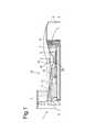
- FIG. 2depicts a fuel injector stalk and head.
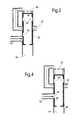
- FIG. 3is a schematic of a valve closed to both air and fuel flow.
- FIG. 4is a schematic of the valve of FIG. 3 opening where the valve is open to purge air but closed to fuel flow.
- FIG. 5is a schematic of the valve of FIGS. 3 and 4 opened where the valve is closed to purge air but open to fuel flow.
- FIG. 6is a schematic of the valve closing where the valve is open to purge air but closed to fuel flow
- the fuel injector 18includes a head 22 and a stalk 20 .
- a passage 24 inside the stalk 20connects nozzles (not shown) in the head with a fuel manifold 26 .
- a fuel supply valve 28 in the stalkcontrols the supply and ejection of fuel to the nozzles for ejection into the combustion chamber 5 .
- a port 30supplies pressurised air to the valve, which controls when the air is used to purge the injector galleries.
- the pressurised air flowing to the injector at operating conditionshas a pressure of around 17 bar (260 psi) and a temperature of the order 720K.
- the air pressure in the combustor and just downstream of the valveis about 95% that of the air inlet pressure to the valve i.e. of the order 16.1 bar. It will be appreciated that these conditions are exemplary and particular injectors and engines will have different pressure and temperature values.
- FIG. 3depicts a control valve according to the invention for the mains fuel supply circuit.
- the valvehas a fuel inlet connected to a fuel manifold 26 ( FIG. 2 ).
- the valvehas a further fuel inlet 42 , which helps to increase the refill time and the speed of response when the valve is opened to supply fuel.
- the fuel inlethas a pressure P manifold which in the closed position of the valve is less than the air pressure at the outlet of the valve 44 , which is at a pressure close to that of the injector head outlet P outlet . There is typically a 5% drop in air pressure across the injector.
- a spool 46is mounted within the sleeve 48 of the valve and is movable linearly within the sleeve.
- the primary driver of the spoolis the pressure difference between the fuel pressure in the manifold P manifold and the pressure at the outlet P outlet .
- a biasing spring 40may be provided which biases the spool in a closed or open position.
- the spoolhas a plurality of apertures 49 , 50 that in the closed position do not match up with the fuel inlets 42 or the purge air inlet 52 . In the closed position there is no fuel or air flow through the nozzle fuel gallery 44 valve outlet.
- the closed position of the valveis of primary use where the engine is at low power requirements and fuel is injected into the combustor through the pilot circuit.
- a stopis provided to prevent the valve sliding further than desired.
- the controllerWhen a demand for greater thrust is sent by the pilot to the engine controller, the controller causes an increase in the fuel pressure and the pressure P manifold . Once P manifold is greater than P outlet the valve spool 46 begins to move within the sleeve 48 . In a transitional phase, shown in FIG. 4 , the aperture 50 in the spool moves over the purge air inlet 52 allowing purge air to flow through the valve to the valve outlet 44 . The apertures 49 , which align with, the fuel supply ports 42 are, in this transitional state, not aligned and fuel supply to the outlet is not enabled.
- the purge airflows through the valve driven by the pressure difference P air ⁇ P outlet .
- an aperture 50having a diameter of 3 mm and a pressure drop of 5.5 bar the aperture remains open for approximately 0.5 seconds and permits a total flow of around 0.2 litres to flow through the valve body.
- the spoolcontinues to be driven by the pressure difference P manifold ⁇ P outlet till it reaches its final position depicted in FIG. 5 .
- the spoolis prevented from travelling further than required by the provision of a stop (not shown).
- the apertures 49align with the fuel supply inlets 42 to enable the flow of fuel through the valve to the injector nozzles. In this position the purge air is disabled as the apertures 50 are beyond the air purge supply.
- valveremains in this position whilst the engine controller is demanding the higher level of power. When it is no longer required to provide this higher level of power the fuel pressure manifold P manifold is reduced. When this falls below the pressure at the injector head the pressure difference causes the spool to move upwards within the sleeve through the transitional position depicted in FIG. 6 .
- the apertures 50aligns with the purge air supply allowing a flow of purge air to pass through the valve to the valve outlet.
- the closing speedis slower than the opening speed such that the flow of purge air is enabled for approximately 6.5 seconds. In this time about 0.7 litres of air pass through the purge valve.
- the fuel galleries downstream of the valvehave a volume of the order 10 cc (0.01 lt) the flow of purge air is sufficient to purge the galleries of any stagnant fuel.
- the present valvehas the advantage of being simple and compact.
- a single valveintegrates the functionality of a purge system that permits the fuel manifolds to remain primed yet permits purging to occur every time the main nozzles are staged in or out.
- the valveprevents a continual flow of purge air when the main injector is not injecting fuel into the combustor cavity and thereby helps to reduce coking of the pilot manifolds and their other features.
- the valvemay also be modified to allow other volumes of purge air to be used depending on the application.
- a modificationmay be by, for example, changing the strength of the spring, altering the port locations and sizes. Some of these modifications can also be used to change the time period for which the purge air is supplied.
- the method of the inventionmay be achieved using a fuel check valve and an air check valve feeding into a common body, which feeds the fuel injector nozzle.
- the air valveis operated to open and close to supply air through the common body before the fuel valve is opened and again following closure of the fuel valve.
- the valvesneed to be appropriately synchronised to avoid both the fuel and air valves being open simultaneously.
- the valvepermits the introduction of air followed by fuel at an appropriate time delay as determined by the speed of movement of the valve spool and the distance between the fuel and air inlet spacing.
Landscapes
- Engineering & Computer Science (AREA)
- Chemical & Material Sciences (AREA)
- Combustion & Propulsion (AREA)
- General Engineering & Computer Science (AREA)
- Mechanical Engineering (AREA)
- Fuel-Injection Apparatus (AREA)
Abstract
Description
This application is entitled to the benefit of British Patent Application No. GB 0809901.2, filed on Jun. 2, 2008.
This invention relates to fuel supply valves for turbine engines.
With reference toFIG. 1 , a ducted fan gas turbine engine generally indicated at10 includes, in axial flow series, an air intake1, apropulsive fan 2, anintermediate pressure compressor 3, a high pressure compressor4,combustion equipment 5, a high pressure turbine6, anintermediate pressure turbine 7, alow pressure turbine 8 and anexhaust nozzle 9.
Air entering the air intake1 is accelerated by thefan 2 to produce two air flows, a first air flow into theintermediate pressure compressor 3 and a second air flow that passes over the outer surface of theengine casing 12 and which provides propulsive thrust. Theintermediate pressure compressor 3 compresses the airflow directed into it before delivering the air to the high-pressure compressor4 where further compression takes place.
Compressed air exhausted from the high-pressure compressor4 is directed into thecombustion equipment 5, where it is mixed with fuel and the mixture combusted. The resultant hot combustion products expand through and thereby drive the high6, intermediate7 and low-pressure 8 turbines before being exhausted through thenozzle 9 to provide additional propulsive thrust. The high, intermediate and low-pressure turbines respectively drive the high and intermediate pressure compressors and the fan by suitable interconnecting shafts.
Fuel is supplied to both sets of nozzles through tubes running the length of the injector stalk. A check valve is located at the end of the stalk opposing the head end. The check valves hold fuel in their upstream manifolds in order to avoid having to prime the manifolds following a demand from the engine controller for more power.
One of the problems with having stagnant fuel in the injector fuel galleries is that at operational temperatures of the engine the fuel can undergo thermal breakdown leading to deposition of carbon in the manifolds in a process known as coking. Heavy coking can block the fuel passages causing, ultimately, failure of the injector amongst other problems.
The fuel upstream of the valve is located in a position cool enough not to suffer from coking and the flow of the pilot fuel is sufficient to keep the temperature of the stagnant fuel below the coking temperature. Downstream of the valve the temperature is high enough for the fuel to coke and it is desirable to purge the galleries and conduits downstream of the valve to remove stagnant fuel.
In U.S. Pat. No. 5,243,816 a valve is provided and is opened and closed by the pressure difference between the fuel supply and the pressure of air coming from the compressor and upstream of the injector. A spring is used to bias the valve into the fuel off position. As will be appreciated from this document whenever the fuel is not flowing into the injector head the purge air is continually flowing through the injector. This arrangement is acceptable in an injector having just one set of nozzles e.g. pilot or main, but in an injector having both sets the continual flow of hotter air through the galleries will increase the temperature of fuel flowing (sometimes slowly) in adjacent galleries above its coking temperature and heatshields which are provided to avoid this situation are bypassed.
It is an object of the present invention to seek to provide an improved fuel valve and injector that addresses these and other problems.
According to a first aspect of the invention there is provided a fuel valve for a turbine engine, the valve having a fuel inlet and an outlet the fuel inlet being suitable for connecting to a supply of fuel, the valve having a purge inlet suitable for connecting to a supply of purge air, the valve having an opening and closing means which enables or disables the supply of fuel and purge air from their respective inlets to the outlet, the opening and closing means being movable in sequence from a first position where both the purge air and fuel to the outlet is disabled to a second position where the purge air is enabled and the fuel is disabled to a third position where the purge air is disabled and the fuel is enabled.
Preferably the opening and closing means includes a spool moveable within valve.
The spool may have at least one aperture that in turn aligns with the purge inlet and fuel inlet as the spool moves within the valve.
Preferably the spool is moveable in a linear translation. As an alternative or in combination the spool may rotate within the valve to align aperture(s) with the fuel and purge inlets.
Preferably the supply of fuel exerts a pressure on the spool wherein the spool is moveable by a pressure difference between the pressure in the fuel inlet and the pressure in the outlet.
A spring is located to bias against the opening means. Any appropriate spring means may be used for the spring.
According to a second aspect of the invention there is provided a of staging a fuel valve, the method having the steps of sequentially opening a flow of purge air to the injector, closing the flow of purge air to the injector, opening a flow of fuel to the injector for injection from the injector into a combustion chamber, closing the flow of fuel to the injector, opening a flow of purge air to the injector, closing the flow of purge air to the injector.
Referring toFIG. 2 thefuel injector 18 includes ahead 22 and astalk 20. Apassage 24 inside thestalk 20 connects nozzles (not shown) in the head with afuel manifold 26. Afuel supply valve 28 in the stalk controls the supply and ejection of fuel to the nozzles for ejection into thecombustion chamber 5. Aport 30 supplies pressurised air to the valve, which controls when the air is used to purge the injector galleries.
The pressurised air flowing to the injector at operating conditions has a pressure of around 17 bar (260 psi) and a temperature of the order 720K. The air pressure in the combustor and just downstream of the valve is about 95% that of the air inlet pressure to the valve i.e. of the order 16.1 bar. It will be appreciated that these conditions are exemplary and particular injectors and engines will have different pressure and temperature values.
Aspool 46 is mounted within thesleeve 48 of the valve and is movable linearly within the sleeve. The primary driver of the spool is the pressure difference between the fuel pressure in the manifold Pmanifoldand the pressure at the outlet Poutlet. If desired abiasing spring 40 may be provided which biases the spool in a closed or open position.
The spool has a plurality ofapertures fuel inlets 42 or thepurge air inlet 52. In the closed position there is no fuel or air flow through thenozzle fuel gallery 44 valve outlet.
The closed position of the valve is of primary use where the engine is at low power requirements and fuel is injected into the combustor through the pilot circuit. A stop is provided to prevent the valve sliding further than desired.
When a demand for greater thrust is sent by the pilot to the engine controller, the controller causes an increase in the fuel pressure and the pressure Pmanifold. Once Pmanifoldis greater than Poutletthevalve spool 46 begins to move within thesleeve 48. In a transitional phase, shown inFIG. 4 , theaperture 50 in the spool moves over thepurge air inlet 52 allowing purge air to flow through the valve to thevalve outlet 44. Theapertures 49, which align with, thefuel supply ports 42 are, in this transitional state, not aligned and fuel supply to the outlet is not enabled.
The purge air flows through the valve driven by the pressure difference Pair−Poutlet. With anaperture 50 having a diameter of 3 mm and a pressure drop of 5.5 bar the aperture remains open for approximately 0.5 seconds and permits a total flow of around 0.2 litres to flow through the valve body.
As the state depicted inFIG. 4 is transitional the spool continues to be driven by the pressure difference Pmanifold−Poutlettill it reaches its final position depicted inFIG. 5 . The spool is prevented from travelling further than required by the provision of a stop (not shown). Theapertures 49 align with thefuel supply inlets 42 to enable the flow of fuel through the valve to the injector nozzles. In this position the purge air is disabled as theapertures 50 are beyond the air purge supply.
The valve remains in this position whilst the engine controller is demanding the higher level of power. When it is no longer required to provide this higher level of power the fuel pressure manifold Pmanifoldis reduced. When this falls below the pressure at the injector head the pressure difference causes the spool to move upwards within the sleeve through the transitional position depicted inFIG. 6 .
Once again, for a short period, theapertures 50 aligns with the purge air supply allowing a flow of purge air to pass through the valve to the valve outlet. The closing speed is slower than the opening speed such that the flow of purge air is enabled for approximately 6.5 seconds. In this time about 0.7 litres of air pass through the purge valve. Considering that the fuel galleries downstream of the valve have a volume of theorder 10 cc (0.01 lt) the flow of purge air is sufficient to purge the galleries of any stagnant fuel.
It will be appreciated that the present valve has the advantage of being simple and compact. A single valve integrates the functionality of a purge system that permits the fuel manifolds to remain primed yet permits purging to occur every time the main nozzles are staged in or out. Beneficially the valve prevents a continual flow of purge air when the main injector is not injecting fuel into the combustor cavity and thereby helps to reduce coking of the pilot manifolds and their other features.
The valve may also be modified to allow other volumes of purge air to be used depending on the application. Such a modification may be by, for example, changing the strength of the spring, altering the port locations and sizes. Some of these modifications can also be used to change the time period for which the purge air is supplied.
In a less elegant modification the method of the invention may be achieved using a fuel check valve and an air check valve feeding into a common body, which feeds the fuel injector nozzle. The air valve is operated to open and close to supply air through the common body before the fuel valve is opened and again following closure of the fuel valve. The valves need to be appropriately synchronised to avoid both the fuel and air valves being open simultaneously.
Whilst the invention has been described with respect to use of the valve and method in turbine engines it will be appreciated that the skilled person will be able to modify the invention for use in other industries, for example, but not exclusively, the automotive industry.
Where the engine is a piston engines, the valve permits the introduction of air followed by fuel at an appropriate time delay as determined by the speed of movement of the valve spool and the distance between the fuel and air inlet spacing.
Claims (4)
1. A fuel valve for a turbine engine, the fuel valve comprising:
a housing comprising:
a cavity formed by an upstream end, a downstream end, and sidewalls connecting the upstream and downstream ends;
an upstream end inlet;
a downstream end outlet;
a fuel inlet located on at least one of the sidewalls and suitable for connecting to a supply of fuel,
a purge inlet located on at least one of the sidewalls and suitable for connecting to a supply of purge air,
a hollow spool disposed within the cavity and movable via a fuel pressure from the upstream end inlet,
the hollow spool comprising: a solid wall facing the upstream end inlet, a first inlet lateral aperture, a second inlet lateral aperture, and an outlet aperture on a wall facing the downstream end outlet which enables or disables the supply of fuel and purge air from the fuel and purge air inlets to the downstream end outlet,
the hollow spool being movable in sequence from a first position where both the first and second inlet lateral apertures are not aligned with the purge air and fuel inlets to a second position where the first inlet lateral aperture is aligned with the purge air inlet and the second lateral inlet aperture is not aligned with the fuel inlet to a third position where the first inlet lateral aperture is not aligned with the purge air inlet and the second inlet lateral aperture is aligned with the fuel inlet.
2. A fuel valve according toclaim 1 , wherein the spool is moveable in a linear translation.
3. A fuel valve according toclaim 1 , wherein the supply of fuel exerts a pressure on the spool wherein the spool is moveable by a pressure difference between the pressure in the fuel inlet and the pressure in the outlet.
4. A fuel valve according toclaim 3 , wherein a spring is located to bias against the opening means.
Applications Claiming Priority (2)
| Application Number | Priority Date | Filing Date | Title |
|---|---|---|---|
| GB0809901.2 | 2008-06-02 | ||
| GB0809901AGB2460634B (en) | 2008-06-02 | 2008-06-02 | Combustion apparatus |
Publications (2)
| Publication Number | Publication Date |
|---|---|
| US20090293492A1 US20090293492A1 (en) | 2009-12-03 |
| US8429892B2true US8429892B2 (en) | 2013-04-30 |
Family
ID=39637906
Family Applications (1)
| Application Number | Title | Priority Date | Filing Date |
|---|---|---|---|
| US12/476,857Expired - Fee RelatedUS8429892B2 (en) | 2008-06-02 | 2009-06-02 | Combustion apparatus having a fuel controlled valve that temporarily flows purging air |
Country Status (2)
| Country | Link |
|---|---|
| US (1) | US8429892B2 (en) |
| GB (1) | GB2460634B (en) |
Cited By (12)
| Publication number | Priority date | Publication date | Assignee | Title |
|---|---|---|---|---|
| US20110049185A1 (en)* | 2008-04-01 | 2011-03-03 | Sergei Aleksandrovich Buchik | Device for dispensing effervescent beverages and a three-way valve |
| US20110100015A1 (en)* | 2009-11-05 | 2011-05-05 | General Electric Company | Gas turbine system to inhibit coke formation and methods of use |
| US20160298850A1 (en)* | 2013-11-20 | 2016-10-13 | Snecma | Multi-point injection device for an aircraft engine |
| US9732668B2 (en)* | 2013-02-07 | 2017-08-15 | Valeo Systemes De Controle Moteur | Discharge valve and associated device |
| US9822900B2 (en) | 2015-07-16 | 2017-11-21 | Honeywell International Inc | Pneumatic mixing valve |
| US20190101061A1 (en)* | 2017-10-02 | 2019-04-04 | United Technologies Corporation | Switching bleed valve for a gas turbine engine |
| US11041626B2 (en) | 2016-03-15 | 2021-06-22 | Rolls-Royce Plc | Combustion chamber system and a method of operating a combustion chamber system |
| US11255269B2 (en)* | 2019-02-05 | 2022-02-22 | Rolls-Royce Plc | Valve arrangement for a fuel system |
| US11391214B2 (en) | 2019-05-15 | 2022-07-19 | Pratt & Whitney Canada Corp. | System and method for purging a fuel manifold of a gas turbine engine using a flow divider assembly |
| US11486303B2 (en) | 2019-05-15 | 2022-11-01 | Pratt & Whitney Canada Corp. | System and method for purging a fuel manifold of a gas turbine engine using a pump |
| US11525410B2 (en) | 2019-10-10 | 2022-12-13 | Pratt & Whitney Canada Corp. | Systems and methods for purging a fuel manifold of a gas turbine engine |
| US11536201B2 (en) | 2019-05-15 | 2022-12-27 | Pratt & Whitney Canada Corp. | System and method for purging a fuel manifold of a gas turbine engine through a flow divider valve |
Families Citing this family (5)
| Publication number | Priority date | Publication date | Assignee | Title |
|---|---|---|---|---|
| US8393156B2 (en)* | 2009-11-09 | 2013-03-12 | Woodward, Inc. | Variable performance valve of a fuel nozzle for a turbine engine |
| EP2959132B1 (en)* | 2013-02-20 | 2020-09-09 | United Technologies Corporation | Self-purging fuel injector system for a gas turbine engine |
| EP3039263B1 (en)* | 2013-08-26 | 2021-09-22 | Hamilton Sundstrand Corporation | Variable pressure air supply |
| DE102013021057B4 (en)* | 2013-12-18 | 2017-06-08 | Grammer Ag | pressure reducer |
| CN113513409B (en)* | 2021-08-20 | 2022-12-20 | 中国联合重型燃气轮机技术有限公司 | Purge system for gas turbine and control method thereof |
Citations (76)
| Publication number | Priority date | Publication date | Assignee | Title |
|---|---|---|---|---|
| US1451887A (en) | 1920-08-10 | 1923-04-17 | Henry Furnace And Foundry Comp | Hot-air conduit |
| US2011329A (en)* | 1935-02-19 | 1935-08-13 | Wayer Henry | Faucet |
| US2617255A (en) | 1947-05-12 | 1952-11-11 | Bbc Brown Boveri & Cie | Combustion chamber for a gas turbine |
| US2858851A (en)* | 1954-09-16 | 1958-11-04 | James W F Holl | Push-pull valve |
| US2916878A (en) | 1958-04-03 | 1959-12-15 | Gen Electric | Air-directing vane structure for fluid fuel combustor |
| US2933895A (en) | 1957-12-31 | 1960-04-26 | Gen Electric | Combustion chamber |
| US3011507A (en)* | 1956-04-13 | 1961-12-05 | Danfoss Ved Ingeniphir Mads Cl | Oil pressure controlled fuel valve, preferably for oil burners |
| US3295280A (en) | 1964-04-09 | 1967-01-03 | S Obermayer Co | Furnace wall anchoring structures |
| US3429683A (en)* | 1966-03-21 | 1969-02-25 | Werner F Jehn | Oral controlled pressure regulator for blowing glass |
| US3533430A (en)* | 1969-01-01 | 1970-01-01 | Otis Eng Corp | Shuttle valve |
| US3678959A (en)* | 1970-07-30 | 1972-07-25 | Richard B Liposky | Hand operable selector valve |
| US3774638A (en)* | 1970-12-18 | 1973-11-27 | Blohm Voss Ag | Multichannel slide valve |
| US4030875A (en) | 1975-12-22 | 1977-06-21 | General Electric Company | Integrated ceramic-metal combustor |
| GB1503921A (en) | 1975-12-19 | 1978-03-15 | Rolls Royce | Method of manufacturing combustion chambers for gas turbine engines |
| US4095418A (en)* | 1975-10-28 | 1978-06-20 | Stal-Laval Turbin Ab | Fuel flushing from injector for combustion chamber |
| US4203458A (en)* | 1978-09-05 | 1980-05-20 | The United States Of America As Represented By The Secretary Of The Air Force | Negative gravity swivel device |
| US4284103A (en)* | 1978-05-08 | 1981-08-18 | Pemberton J C | Random access valve |
| US4315405A (en) | 1978-12-09 | 1982-02-16 | Rolls-Royce Limited | Combustion apparatus |
| US4343601A (en)* | 1980-04-21 | 1982-08-10 | Eaton Corporation | Fluid pressure device and shuttle valve assembly therefor |
| US4454892A (en)* | 1982-09-13 | 1984-06-19 | Combustion Engineering, Inc. | Atomizing oil valve improvement |
| GB2148949A (en) | 1983-10-26 | 1985-06-05 | Bbc Brown Boveri & Cie | Method and apparatus for the zone-annealing of a workpiece consisting of a high-temperature material |
| US4628694A (en) | 1983-12-19 | 1986-12-16 | General Electric Company | Fabricated liner article and method |
| US4652476A (en) | 1985-02-05 | 1987-03-24 | United Technologies Corporation | Reinforced ablative thermal barriers |
| US4793591A (en)* | 1987-12-11 | 1988-12-27 | Templeton, Kenly & Co. | Hydraulic shear seal valve including slide bearing |
| US5000005A (en) | 1988-08-17 | 1991-03-19 | Rolls-Royce, Plc | Combustion chamber for a gas turbine engine |
| US5046702A (en)* | 1987-03-14 | 1991-09-10 | Kabushiki Kaisha Kambayashi Seisakujo | Solenoid device |
| US5050385A (en) | 1982-10-06 | 1991-09-24 | Hitachi, Ltd. | Inner cylinder for a gas turbine combustor reinforced by built up welding |
| US5137586A (en) | 1991-01-02 | 1992-08-11 | Klink James H | Method for continuous annealing of metal strips |
| US5285809A (en)* | 1991-10-11 | 1994-02-15 | Fukuhara Corporation | Drain discharge device |
| US5331816A (en) | 1992-10-13 | 1994-07-26 | United Technologies Corporation | Gas turbine engine combustor fiber reinforced glass ceramic matrix liner with embedded refractory ceramic tiles |
| US5341769A (en) | 1991-12-12 | 1994-08-30 | Kabushiki Kaisha Kobe Seiko Sho | Vaporizer for liquefied natural gas |
| US5405261A (en) | 1992-12-15 | 1995-04-11 | Free Heat, Inc. | Waste oil fired heater with improved two-stage combustion chamber |
| US5449422A (en) | 1992-12-19 | 1995-09-12 | Klockner-Humboldt-Deutz Ag | Method and device for the heat treatment of heat treatable material in an industrial furnace |
| JPH0821687A (en) | 1994-07-06 | 1996-01-23 | Hitachi Zosen Corp | Side wall structure of refractory bricks and incinerators |
| US5553455A (en) | 1987-12-21 | 1996-09-10 | United Technologies Corporation | Hybrid ceramic article |
| US5577379A (en) | 1994-12-15 | 1996-11-26 | United Technologies Corporation | Fuel nozzle guide retainer assembly |
| US5701732A (en)* | 1995-01-24 | 1997-12-30 | Delavan Inc. | Method and apparatus for purging of gas turbine injectors |
| US5709919A (en) | 1993-12-17 | 1998-01-20 | Abb Patent Gmbh | Thermal insulation |
| US5782294A (en) | 1995-12-18 | 1998-07-21 | United Technologies Corporation | Cooled liner apparatus |
| US5799491A (en) | 1995-02-23 | 1998-09-01 | Rolls-Royce Plc | Arrangement of heat resistant tiles for a gas turbine engine combustor |
| US5957067A (en) | 1997-07-28 | 1999-09-28 | Abb Research Ltd. | Ceramic liner |
| US6050081A (en)* | 1997-02-12 | 2000-04-18 | Jansens Aircraft Systems Controls | Air purging fuel valve for turbine engine |
| US6174389B1 (en) | 1999-08-17 | 2001-01-16 | Caterpillar Inc. | Fixture and method for selectively quenching a predetermined area of a workpiece |
| US6182442B1 (en) | 1998-02-04 | 2001-02-06 | Daimlerchrysler Ag | Combustion chamber wall construction for high power engines and thrust nozzles |
| GB2353589A (en) | 1999-08-24 | 2001-02-28 | Rolls Royce Plc | Combustor wall arrangement with air intake port |
| US6199371B1 (en) | 1998-10-15 | 2001-03-13 | United Technologies Corporation | Thermally compliant liner |
| GB2361304A (en) | 2000-04-14 | 2001-10-17 | Rolls Royce Plc | Combustor wall tile |
| US6351949B1 (en) | 1999-09-03 | 2002-03-05 | Allison Advanced Development Company | Interchangeable combustor chute |
| US20020026784A1 (en)* | 1998-05-08 | 2002-03-07 | Yukimasa Nakamoto | Gas turbine fuel system comprising fuel oil distribution control system, fuel oil purge system, purging air supply system and fuel nozzle wash system |
| US6438963B1 (en)* | 2000-08-31 | 2002-08-27 | General Electric Company | Liquid fuel and water injection purge systems and method for a gas turbine having a three-way purge valve |
| US6470685B2 (en) | 2000-04-14 | 2002-10-29 | Rolls-Royce Plc | Combustion apparatus |
| US20020184892A1 (en) | 2001-06-06 | 2002-12-12 | Snecma Moteurs | Fastening a CMC combustion chamber in a turbomachine using brazed tabs |
| DE10136196A1 (en) | 2001-07-25 | 2003-02-06 | Koenig & Bauer Ag | Process for surface hardening steel workpieces used for radial cams comprises heating workpiece using gas-oxygen flame in the region of the surface, cooling using an oil emulsion after heating, and blowing air through flame and oil emulsion |
| US20030056516A1 (en) | 2001-09-21 | 2003-03-27 | Honeywell International, Inc. | Waffle cooling |
| US20030079475A1 (en) | 2001-10-15 | 2003-05-01 | Milan Schmahl | Lining for inner walls of combustion chambers |
| US20040110041A1 (en) | 2002-09-06 | 2004-06-10 | Merrill Gary B. | Ceramic material having ceramic matrix composite backing and method of manufacturing |
| US20040118127A1 (en) | 2002-12-20 | 2004-06-24 | Mitchell Krista Anne | Mounting assembly for the aft end of a ceramic matrix composite liner in a gas turbine engine combustor |
| US6770325B2 (en) | 2000-05-19 | 2004-08-03 | The University Of British Columbia | Process for making chemically bonded composite hydroxide ceramics |
| US20050034399A1 (en) | 2002-01-15 | 2005-02-17 | Rolls-Royce Plc | Double wall combustor tile arrangement |
| US6901757B2 (en) | 2001-11-12 | 2005-06-07 | Rolls-Royce Deutschland Ltd & Co Kg | Heat shield arrangement with sealing element |
| US6931831B2 (en) | 2002-06-18 | 2005-08-23 | Jansen's Aircraft Systems Controls, Inc. | Distributor purge valve |
| US20050238859A1 (en) | 2003-12-15 | 2005-10-27 | Tomonori Uchimaru | Metal member-buried ceramics article and method of producing the same |
| US20060070655A1 (en)* | 2002-11-12 | 2006-04-06 | Dunlop Aerospace Limited | Valve |
| US7024862B2 (en) | 2002-05-31 | 2006-04-11 | Mitsubishi Heavy Industries, Ltd. | System and method for controlling combustion in gas turbine with annular combustor |
| US20060242914A1 (en) | 2005-04-29 | 2006-11-02 | Harbison-Walker Refractories Company | Refractory block and refractory wall assembly |
| EP1734136A2 (en) | 2005-06-15 | 2006-12-20 | Rolls-Royce plc | Method and apparatus for the treatment of a component |
| EP1741891A1 (en) | 2005-07-06 | 2007-01-10 | Delphi Technologies, Inc. | An exhaust treatment device and method of making the same |
| US20070028620A1 (en) | 2005-07-25 | 2007-02-08 | General Electric Company | Free floating mixer assembly for combustor of a gas turbine engine |
| US20070028592A1 (en) | 2003-10-27 | 2007-02-08 | Holger Grote | Thermal shield, especially for lining the wall of a combustion chamber |
| US20070107710A1 (en) | 2005-06-14 | 2007-05-17 | Snecma | Assembling an annular combustion chamber of a turbomachine |
| US20070234730A1 (en) | 2002-06-28 | 2007-10-11 | Markham James R | Method and apparatus for monitoring combustion instability and other performance deviations in turbine engines and like combustion systems |
| US7281529B2 (en)* | 2005-10-17 | 2007-10-16 | International Engine Intellectual Property Company, Llc | EGR cooler purging apparatus and method |
| US20070246149A1 (en) | 2003-11-07 | 2007-10-25 | General Electric Company | Method for fabricating integral composite structural material |
| US20070289307A1 (en) | 2004-12-01 | 2007-12-20 | Holger Grote | Heat Shield Element, Method and Mold for the Production Thereof, Hot-Gas Lining and Combustion Chamber |
| US20080099465A1 (en) | 2006-01-12 | 2008-05-01 | General Electric Company | Localized heat treating apparatus for blisk airfoils |
| US7658201B2 (en)* | 2003-10-28 | 2010-02-09 | Keofitt A/S | Valve for sterile sampling of a liquid sample from a container |
- 2008
- 2008-06-02GBGB0809901Apatent/GB2460634B/ennot_activeExpired - Fee Related
- 2009
- 2009-06-02USUS12/476,857patent/US8429892B2/ennot_activeExpired - Fee Related
Patent Citations (76)
| Publication number | Priority date | Publication date | Assignee | Title |
|---|---|---|---|---|
| US1451887A (en) | 1920-08-10 | 1923-04-17 | Henry Furnace And Foundry Comp | Hot-air conduit |
| US2011329A (en)* | 1935-02-19 | 1935-08-13 | Wayer Henry | Faucet |
| US2617255A (en) | 1947-05-12 | 1952-11-11 | Bbc Brown Boveri & Cie | Combustion chamber for a gas turbine |
| US2858851A (en)* | 1954-09-16 | 1958-11-04 | James W F Holl | Push-pull valve |
| US3011507A (en)* | 1956-04-13 | 1961-12-05 | Danfoss Ved Ingeniphir Mads Cl | Oil pressure controlled fuel valve, preferably for oil burners |
| US2933895A (en) | 1957-12-31 | 1960-04-26 | Gen Electric | Combustion chamber |
| US2916878A (en) | 1958-04-03 | 1959-12-15 | Gen Electric | Air-directing vane structure for fluid fuel combustor |
| US3295280A (en) | 1964-04-09 | 1967-01-03 | S Obermayer Co | Furnace wall anchoring structures |
| US3429683A (en)* | 1966-03-21 | 1969-02-25 | Werner F Jehn | Oral controlled pressure regulator for blowing glass |
| US3533430A (en)* | 1969-01-01 | 1970-01-01 | Otis Eng Corp | Shuttle valve |
| US3678959A (en)* | 1970-07-30 | 1972-07-25 | Richard B Liposky | Hand operable selector valve |
| US3774638A (en)* | 1970-12-18 | 1973-11-27 | Blohm Voss Ag | Multichannel slide valve |
| US4095418A (en)* | 1975-10-28 | 1978-06-20 | Stal-Laval Turbin Ab | Fuel flushing from injector for combustion chamber |
| GB1503921A (en) | 1975-12-19 | 1978-03-15 | Rolls Royce | Method of manufacturing combustion chambers for gas turbine engines |
| US4030875A (en) | 1975-12-22 | 1977-06-21 | General Electric Company | Integrated ceramic-metal combustor |
| US4284103A (en)* | 1978-05-08 | 1981-08-18 | Pemberton J C | Random access valve |
| US4203458A (en)* | 1978-09-05 | 1980-05-20 | The United States Of America As Represented By The Secretary Of The Air Force | Negative gravity swivel device |
| US4315405A (en) | 1978-12-09 | 1982-02-16 | Rolls-Royce Limited | Combustion apparatus |
| US4343601A (en)* | 1980-04-21 | 1982-08-10 | Eaton Corporation | Fluid pressure device and shuttle valve assembly therefor |
| US4454892A (en)* | 1982-09-13 | 1984-06-19 | Combustion Engineering, Inc. | Atomizing oil valve improvement |
| US5050385A (en) | 1982-10-06 | 1991-09-24 | Hitachi, Ltd. | Inner cylinder for a gas turbine combustor reinforced by built up welding |
| GB2148949A (en) | 1983-10-26 | 1985-06-05 | Bbc Brown Boveri & Cie | Method and apparatus for the zone-annealing of a workpiece consisting of a high-temperature material |
| US4628694A (en) | 1983-12-19 | 1986-12-16 | General Electric Company | Fabricated liner article and method |
| US4652476A (en) | 1985-02-05 | 1987-03-24 | United Technologies Corporation | Reinforced ablative thermal barriers |
| US5046702A (en)* | 1987-03-14 | 1991-09-10 | Kabushiki Kaisha Kambayashi Seisakujo | Solenoid device |
| US4793591A (en)* | 1987-12-11 | 1988-12-27 | Templeton, Kenly & Co. | Hydraulic shear seal valve including slide bearing |
| US5553455A (en) | 1987-12-21 | 1996-09-10 | United Technologies Corporation | Hybrid ceramic article |
| US5000005A (en) | 1988-08-17 | 1991-03-19 | Rolls-Royce, Plc | Combustion chamber for a gas turbine engine |
| US5137586A (en) | 1991-01-02 | 1992-08-11 | Klink James H | Method for continuous annealing of metal strips |
| US5285809A (en)* | 1991-10-11 | 1994-02-15 | Fukuhara Corporation | Drain discharge device |
| US5341769A (en) | 1991-12-12 | 1994-08-30 | Kabushiki Kaisha Kobe Seiko Sho | Vaporizer for liquefied natural gas |
| US5331816A (en) | 1992-10-13 | 1994-07-26 | United Technologies Corporation | Gas turbine engine combustor fiber reinforced glass ceramic matrix liner with embedded refractory ceramic tiles |
| US5405261A (en) | 1992-12-15 | 1995-04-11 | Free Heat, Inc. | Waste oil fired heater with improved two-stage combustion chamber |
| US5449422A (en) | 1992-12-19 | 1995-09-12 | Klockner-Humboldt-Deutz Ag | Method and device for the heat treatment of heat treatable material in an industrial furnace |
| US5709919A (en) | 1993-12-17 | 1998-01-20 | Abb Patent Gmbh | Thermal insulation |
| JPH0821687A (en) | 1994-07-06 | 1996-01-23 | Hitachi Zosen Corp | Side wall structure of refractory bricks and incinerators |
| US5577379A (en) | 1994-12-15 | 1996-11-26 | United Technologies Corporation | Fuel nozzle guide retainer assembly |
| US5701732A (en)* | 1995-01-24 | 1997-12-30 | Delavan Inc. | Method and apparatus for purging of gas turbine injectors |
| US5799491A (en) | 1995-02-23 | 1998-09-01 | Rolls-Royce Plc | Arrangement of heat resistant tiles for a gas turbine engine combustor |
| US5782294A (en) | 1995-12-18 | 1998-07-21 | United Technologies Corporation | Cooled liner apparatus |
| US6050081A (en)* | 1997-02-12 | 2000-04-18 | Jansens Aircraft Systems Controls | Air purging fuel valve for turbine engine |
| US5957067A (en) | 1997-07-28 | 1999-09-28 | Abb Research Ltd. | Ceramic liner |
| US6182442B1 (en) | 1998-02-04 | 2001-02-06 | Daimlerchrysler Ag | Combustion chamber wall construction for high power engines and thrust nozzles |
| US20020026784A1 (en)* | 1998-05-08 | 2002-03-07 | Yukimasa Nakamoto | Gas turbine fuel system comprising fuel oil distribution control system, fuel oil purge system, purging air supply system and fuel nozzle wash system |
| US6199371B1 (en) | 1998-10-15 | 2001-03-13 | United Technologies Corporation | Thermally compliant liner |
| US6174389B1 (en) | 1999-08-17 | 2001-01-16 | Caterpillar Inc. | Fixture and method for selectively quenching a predetermined area of a workpiece |
| GB2353589A (en) | 1999-08-24 | 2001-02-28 | Rolls Royce Plc | Combustor wall arrangement with air intake port |
| US6351949B1 (en) | 1999-09-03 | 2002-03-05 | Allison Advanced Development Company | Interchangeable combustor chute |
| US6470685B2 (en) | 2000-04-14 | 2002-10-29 | Rolls-Royce Plc | Combustion apparatus |
| GB2361304A (en) | 2000-04-14 | 2001-10-17 | Rolls Royce Plc | Combustor wall tile |
| US6770325B2 (en) | 2000-05-19 | 2004-08-03 | The University Of British Columbia | Process for making chemically bonded composite hydroxide ceramics |
| US6438963B1 (en)* | 2000-08-31 | 2002-08-27 | General Electric Company | Liquid fuel and water injection purge systems and method for a gas turbine having a three-way purge valve |
| US20020184892A1 (en) | 2001-06-06 | 2002-12-12 | Snecma Moteurs | Fastening a CMC combustion chamber in a turbomachine using brazed tabs |
| DE10136196A1 (en) | 2001-07-25 | 2003-02-06 | Koenig & Bauer Ag | Process for surface hardening steel workpieces used for radial cams comprises heating workpiece using gas-oxygen flame in the region of the surface, cooling using an oil emulsion after heating, and blowing air through flame and oil emulsion |
| US20030056516A1 (en) | 2001-09-21 | 2003-03-27 | Honeywell International, Inc. | Waffle cooling |
| US20030079475A1 (en) | 2001-10-15 | 2003-05-01 | Milan Schmahl | Lining for inner walls of combustion chambers |
| US6901757B2 (en) | 2001-11-12 | 2005-06-07 | Rolls-Royce Deutschland Ltd & Co Kg | Heat shield arrangement with sealing element |
| US20050034399A1 (en) | 2002-01-15 | 2005-02-17 | Rolls-Royce Plc | Double wall combustor tile arrangement |
| US7024862B2 (en) | 2002-05-31 | 2006-04-11 | Mitsubishi Heavy Industries, Ltd. | System and method for controlling combustion in gas turbine with annular combustor |
| US6931831B2 (en) | 2002-06-18 | 2005-08-23 | Jansen's Aircraft Systems Controls, Inc. | Distributor purge valve |
| US20070234730A1 (en) | 2002-06-28 | 2007-10-11 | Markham James R | Method and apparatus for monitoring combustion instability and other performance deviations in turbine engines and like combustion systems |
| US20040110041A1 (en) | 2002-09-06 | 2004-06-10 | Merrill Gary B. | Ceramic material having ceramic matrix composite backing and method of manufacturing |
| US20060070655A1 (en)* | 2002-11-12 | 2006-04-06 | Dunlop Aerospace Limited | Valve |
| US20040118127A1 (en) | 2002-12-20 | 2004-06-24 | Mitchell Krista Anne | Mounting assembly for the aft end of a ceramic matrix composite liner in a gas turbine engine combustor |
| US20070028592A1 (en) | 2003-10-27 | 2007-02-08 | Holger Grote | Thermal shield, especially for lining the wall of a combustion chamber |
| US7658201B2 (en)* | 2003-10-28 | 2010-02-09 | Keofitt A/S | Valve for sterile sampling of a liquid sample from a container |
| US20070246149A1 (en) | 2003-11-07 | 2007-10-25 | General Electric Company | Method for fabricating integral composite structural material |
| US20050238859A1 (en) | 2003-12-15 | 2005-10-27 | Tomonori Uchimaru | Metal member-buried ceramics article and method of producing the same |
| US20070289307A1 (en) | 2004-12-01 | 2007-12-20 | Holger Grote | Heat Shield Element, Method and Mold for the Production Thereof, Hot-Gas Lining and Combustion Chamber |
| US20060242914A1 (en) | 2005-04-29 | 2006-11-02 | Harbison-Walker Refractories Company | Refractory block and refractory wall assembly |
| US20070107710A1 (en) | 2005-06-14 | 2007-05-17 | Snecma | Assembling an annular combustion chamber of a turbomachine |
| EP1734136A2 (en) | 2005-06-15 | 2006-12-20 | Rolls-Royce plc | Method and apparatus for the treatment of a component |
| EP1741891A1 (en) | 2005-07-06 | 2007-01-10 | Delphi Technologies, Inc. | An exhaust treatment device and method of making the same |
| US20070028620A1 (en) | 2005-07-25 | 2007-02-08 | General Electric Company | Free floating mixer assembly for combustor of a gas turbine engine |
| US7281529B2 (en)* | 2005-10-17 | 2007-10-16 | International Engine Intellectual Property Company, Llc | EGR cooler purging apparatus and method |
| US20080099465A1 (en) | 2006-01-12 | 2008-05-01 | General Electric Company | Localized heat treating apparatus for blisk airfoils |
Cited By (21)
| Publication number | Priority date | Publication date | Assignee | Title |
|---|---|---|---|---|
| US8678048B2 (en)* | 2008-04-01 | 2014-03-25 | Sergei Aleksandrovich Buchik | Device for dispensing effervescent beverages and a three-way valve |
| US20110049185A1 (en)* | 2008-04-01 | 2011-03-03 | Sergei Aleksandrovich Buchik | Device for dispensing effervescent beverages and a three-way valve |
| US20110100015A1 (en)* | 2009-11-05 | 2011-05-05 | General Electric Company | Gas turbine system to inhibit coke formation and methods of use |
| US9732668B2 (en)* | 2013-02-07 | 2017-08-15 | Valeo Systemes De Controle Moteur | Discharge valve and associated device |
| US10465910B2 (en)* | 2013-11-20 | 2019-11-05 | Safran Aircraft Engines | Multi-point injection device for an aircraft engine |
| US20160298850A1 (en)* | 2013-11-20 | 2016-10-13 | Snecma | Multi-point injection device for an aircraft engine |
| US9822900B2 (en) | 2015-07-16 | 2017-11-21 | Honeywell International Inc | Pneumatic mixing valve |
| US10228074B2 (en) | 2015-07-16 | 2019-03-12 | Honeywell International Inc. | Pneumatic mixing valve |
| US11041626B2 (en) | 2016-03-15 | 2021-06-22 | Rolls-Royce Plc | Combustion chamber system and a method of operating a combustion chamber system |
| US10487751B2 (en)* | 2017-10-02 | 2019-11-26 | United Technologies Corporation | Switching bleed valve for a gas turbine engine |
| US20190101061A1 (en)* | 2017-10-02 | 2019-04-04 | United Technologies Corporation | Switching bleed valve for a gas turbine engine |
| US11255269B2 (en)* | 2019-02-05 | 2022-02-22 | Rolls-Royce Plc | Valve arrangement for a fuel system |
| US11391214B2 (en) | 2019-05-15 | 2022-07-19 | Pratt & Whitney Canada Corp. | System and method for purging a fuel manifold of a gas turbine engine using a flow divider assembly |
| US11486303B2 (en) | 2019-05-15 | 2022-11-01 | Pratt & Whitney Canada Corp. | System and method for purging a fuel manifold of a gas turbine engine using a pump |
| US11536201B2 (en) | 2019-05-15 | 2022-12-27 | Pratt & Whitney Canada Corp. | System and method for purging a fuel manifold of a gas turbine engine through a flow divider valve |
| US11732653B2 (en) | 2019-05-15 | 2023-08-22 | Pratt & Whitney Canada Corp. | System and method for purging a fuel manifold of a gas turbine engine through a flow divider valve |
| US11846236B2 (en) | 2019-05-15 | 2023-12-19 | Pratt & Whitney Canada Corp. | System and method for purging a fuel manifold of a gas turbine engine using a flow divider assembly |
| US12163474B2 (en) | 2019-05-15 | 2024-12-10 | Pratt & Whitney Canada Corp. | System and method for purging a fuel manifold of a gas turbine engine using a flow divider assembly |
| US12180895B2 (en) | 2019-05-15 | 2024-12-31 | Pratt & Whitney Canada Corp. | System and method for purging a fuel manifold of a gas turbine engine through a flow divider valve |
| US11525410B2 (en) | 2019-10-10 | 2022-12-13 | Pratt & Whitney Canada Corp. | Systems and methods for purging a fuel manifold of a gas turbine engine |
| US12018616B2 (en) | 2019-10-10 | 2024-06-25 | Pratt & Whitney Canada Corp. | Systems and methods for purging a fuel manifold of a gas turbine engine |
Also Published As
| Publication number | Publication date |
|---|---|
| GB2460634A (en) | 2009-12-09 |
| US20090293492A1 (en) | 2009-12-03 |
| GB2460634B (en) | 2010-07-07 |
| GB0809901D0 (en) | 2008-07-09 |
Similar Documents
| Publication | Publication Date | Title |
|---|---|---|
| US8429892B2 (en) | Combustion apparatus having a fuel controlled valve that temporarily flows purging air | |
| US10982858B2 (en) | Combustion staging system | |
| EP3070408B1 (en) | Combustion staging system | |
| US4305255A (en) | Combined pilot and main burner | |
| CN105257444B (en) | Fuel valve and method for injecting gaseous fuel into a combustion chamber of a self-igniting internal combustion engine | |
| US20180163637A1 (en) | Fuel supply system | |
| CN203130313U (en) | Dual Fuel Injection Valves for Diesel and Gas Engines with Pumping Function Nozzles | |
| US20180163636A1 (en) | Fuel supply system | |
| EP2138688B1 (en) | A fuel control arrangement | |
| WO2013147632A1 (en) | Bi-directional end cover with extraction capability for gas turbine combustor | |
| RU2618800C2 (en) | Fuel valve and method for gaseous fuel injection into combustion chamber of internal combustion engine | |
| CN104454192A (en) | Fuel valves for pilot oil injection and injection of gaseous fuel into the combustion chamber | |
| US10815893B2 (en) | Combustor assembly with primary and auxiliary injector fuel control | |
| CN105986944A (en) | Fuel valve for injecting a low flashpoint fuel into a combustion chamber of an internal combustion engine | |
| CN108131229B (en) | Fuel valve and method for injecting liquid fuel into engine combustion chamber and engine | |
| US11225933B2 (en) | Twin outlet check liquid fuel injector for dual fuel system | |
| JP6276796B2 (en) | Fuel valve for injecting fuel into the combustion chamber of a turbocharged large two-stroke self-ignition internal combustion engine | |
| JP2018091335A (en) | Fuel valve for large-sized turbocharged two-stroke compression ignition internal combustion engine and internal combustion engine using the same | |
| US6848250B2 (en) | Fuel injection system for a combustion engine | |
| CN111456851B (en) | Assembly for a turbomachine |
Legal Events
| Date | Code | Title | Description |
|---|---|---|---|
| AS | Assignment | Owner name:ROLLS-ROYCE PLC, UNITED KINGDOM Free format text:ASSIGNMENT OF ASSIGNORS INTEREST;ASSIGNOR:TENTORIO, LUCA;REEL/FRAME:022771/0858 Effective date:20090401 | |
| STCF | Information on status: patent grant | Free format text:PATENTED CASE | |
| FPAY | Fee payment | Year of fee payment:4 | |
| MAFP | Maintenance fee payment | Free format text:PAYMENT OF MAINTENANCE FEE, 8TH YEAR, LARGE ENTITY (ORIGINAL EVENT CODE: M1552); ENTITY STATUS OF PATENT OWNER: LARGE ENTITY Year of fee payment:8 | |
| FEPP | Fee payment procedure | Free format text:MAINTENANCE FEE REMINDER MAILED (ORIGINAL EVENT CODE: REM.); ENTITY STATUS OF PATENT OWNER: LARGE ENTITY | |
| LAPS | Lapse for failure to pay maintenance fees | Free format text:PATENT EXPIRED FOR FAILURE TO PAY MAINTENANCE FEES (ORIGINAL EVENT CODE: EXP.); ENTITY STATUS OF PATENT OWNER: LARGE ENTITY | |
| STCH | Information on status: patent discontinuation | Free format text:PATENT EXPIRED DUE TO NONPAYMENT OF MAINTENANCE FEES UNDER 37 CFR 1.362 | |
| FP | Lapsed due to failure to pay maintenance fee | Effective date:20250430 |