US8429880B2 - System for filling, capping, cooling and handling containers - Google Patents
System for filling, capping, cooling and handling containersDownload PDFInfo
- Publication number
- US8429880B2 US8429880B2US13/450,872US201213450872AUS8429880B2US 8429880 B2US8429880 B2US 8429880B2US 201213450872 AUS201213450872 AUS 201213450872AUS 8429880 B2US8429880 B2US 8429880B2
- Authority
- US
- United States
- Prior art keywords
- container
- containers
- vacuum
- annular
- touch points
- Prior art date
- Legal status (The legal status is an assumption and is not a legal conclusion. Google has not performed a legal analysis and makes no representation as to the accuracy of the status listed.)
- Active
Links
- 238000001816coolingMethods0.000titleclaimsdescription42
- 230000000153supplemental effectEffects0.000claimsabstractdescription20
- 239000004033plasticSubstances0.000claimsdescription35
- 229920003023plasticPolymers0.000claimsdescription35
- 239000011159matrix materialSubstances0.000claimsdescription9
- 238000007789sealingMethods0.000claimsdescription3
- 230000004044responseEffects0.000claimsdescription2
- 238000000034methodMethods0.000abstractdescription40
- 239000000463materialSubstances0.000description12
- 230000003213activating effectEffects0.000description10
- 230000004913activationEffects0.000description10
- 230000008569processEffects0.000description5
- 239000012530fluidSubstances0.000description4
- -1polyethylenePolymers0.000description4
- 238000000071blow mouldingMethods0.000description3
- 239000010410layerSubstances0.000description3
- 239000004698PolyethyleneSubstances0.000description2
- 239000000654additiveSubstances0.000description2
- IKZZIQXKLWDPCD-UHFFFAOYSA-Nbut-1-en-2-olChemical compoundCCC(O)=CIKZZIQXKLWDPCD-UHFFFAOYSA-N0.000description2
- 235000014171carbonated beverageNutrition0.000description2
- 230000008859changeEffects0.000description2
- 229920001903high density polyethylenePolymers0.000description2
- 239000004700high-density polyethyleneSubstances0.000description2
- 229920001684low density polyethylenePolymers0.000description2
- 239000004702low-density polyethyleneSubstances0.000description2
- 230000007246mechanismEffects0.000description2
- 230000004048modificationEffects0.000description2
- 238000012986modificationMethods0.000description2
- 229920000573polyethylenePolymers0.000description2
- 239000005020polyethylene terephthalateSubstances0.000description2
- 229920000139polyethylene terephthalatePolymers0.000description2
- 239000002356single layerSubstances0.000description2
- XLYOFNOQVPJJNP-UHFFFAOYSA-NwaterSubstancesOXLYOFNOQVPJJNP-UHFFFAOYSA-N0.000description2
- 239000004677NylonSubstances0.000description1
- 239000004952PolyamideSubstances0.000description1
- 239000004743PolypropyleneSubstances0.000description1
- 241001122767TheaceaeSpecies0.000description1
- 239000012080ambient airSubstances0.000description1
- QVGXLLKOCUKJST-UHFFFAOYSA-Natomic oxygenChemical compound[O]QVGXLLKOCUKJST-UHFFFAOYSA-N0.000description1
- 230000004888barrier functionEffects0.000description1
- 238000007664blowingMethods0.000description1
- 239000011248coating agentSubstances0.000description1
- 238000000576coating methodMethods0.000description1
- 238000010276constructionMethods0.000description1
- 239000002826coolantSubstances0.000description1
- 230000032798delaminationEffects0.000description1
- 238000007373indentationMethods0.000description1
- 238000002347injectionMethods0.000description1
- 239000007924injectionSubstances0.000description1
- 238000002372labellingMethods0.000description1
- 238000004519manufacturing processMethods0.000description1
- 229920001778nylonPolymers0.000description1
- 229910052760oxygenInorganic materials0.000description1
- 239000001301oxygenSubstances0.000description1
- 238000004806packaging method and processMethods0.000description1
- 230000000704physical effectEffects0.000description1
- 229920002647polyamidePolymers0.000description1
- 229920000728polyesterPolymers0.000description1
- 229920000098polyolefinPolymers0.000description1
- 229920001155polypropylenePolymers0.000description1
- 238000000275quality assuranceMethods0.000description1
- 230000009467reductionEffects0.000description1
- 235000011496sports drinkNutrition0.000description1
- 230000006641stabilisationEffects0.000description1
- 238000011105stabilizationMethods0.000description1
- 239000000126substanceSubstances0.000description1
Images


Classifications
- B—PERFORMING OPERATIONS; TRANSPORTING
- B67—OPENING, CLOSING OR CLEANING BOTTLES, JARS OR SIMILAR CONTAINERS; LIQUID HANDLING
- B67C—CLEANING, FILLING WITH LIQUIDS OR SEMILIQUIDS, OR EMPTYING, OF BOTTLES, JARS, CANS, CASKS, BARRELS, OR SIMILAR CONTAINERS, NOT OTHERWISE PROVIDED FOR; FUNNELS
- B67C3/00—Bottling liquids or semiliquids; Filling jars or cans with liquids or semiliquids using bottling or like apparatus; Filling casks or barrels with liquids or semiliquids
- B67C3/02—Bottling liquids or semiliquids; Filling jars or cans with liquids or semiliquids using bottling or like apparatus
- B67C3/04—Bottling liquids or semiliquids; Filling jars or cans with liquids or semiliquids using bottling or like apparatus without applying pressure
- B67C3/045—Apparatus specially adapted for filling bottles with hot liquids
- B—PERFORMING OPERATIONS; TRANSPORTING
- B65—CONVEYING; PACKING; STORING; HANDLING THIN OR FILAMENTARY MATERIAL
- B65B—MACHINES, APPARATUS OR DEVICES FOR, OR METHODS OF, PACKAGING ARTICLES OR MATERIALS; UNPACKING
- B65B61/00—Auxiliary devices, not otherwise provided for, for operating on sheets, blanks, webs, binding material, containers or packages
- B65B61/24—Auxiliary devices, not otherwise provided for, for operating on sheets, blanks, webs, binding material, containers or packages for shaping or reshaping completed packages
- B—PERFORMING OPERATIONS; TRANSPORTING
- B65—CONVEYING; PACKING; STORING; HANDLING THIN OR FILAMENTARY MATERIAL
- B65D—CONTAINERS FOR STORAGE OR TRANSPORT OF ARTICLES OR MATERIALS, e.g. BAGS, BARRELS, BOTTLES, BOXES, CANS, CARTONS, CRATES, DRUMS, JARS, TANKS, HOPPERS, FORWARDING CONTAINERS; ACCESSORIES, CLOSURES, OR FITTINGS THEREFOR; PACKAGING ELEMENTS; PACKAGES
- B65D1/00—Rigid or semi-rigid containers having bodies formed in one piece, e.g. by casting metallic material, by moulding plastics, by blowing vitreous material, by throwing ceramic material, by moulding pulped fibrous material or by deep-drawing operations performed on sheet material
- B65D1/02—Bottles or similar containers with necks or like restricted apertures, designed for pouring contents
- B65D1/0223—Bottles or similar containers with necks or like restricted apertures, designed for pouring contents characterised by shape
- B65D1/0261—Bottom construction
- B—PERFORMING OPERATIONS; TRANSPORTING
- B65—CONVEYING; PACKING; STORING; HANDLING THIN OR FILAMENTARY MATERIAL
- B65B—MACHINES, APPARATUS OR DEVICES FOR, OR METHODS OF, PACKAGING ARTICLES OR MATERIALS; UNPACKING
- B65B61/00—Auxiliary devices, not otherwise provided for, for operating on sheets, blanks, webs, binding material, containers or packages
- B65B61/28—Auxiliary devices, not otherwise provided for, for operating on sheets, blanks, webs, binding material, containers or packages for discharging completed packages from machines
- B—PERFORMING OPERATIONS; TRANSPORTING
- B65—CONVEYING; PACKING; STORING; HANDLING THIN OR FILAMENTARY MATERIAL
- B65D—CONTAINERS FOR STORAGE OR TRANSPORT OF ARTICLES OR MATERIALS, e.g. BAGS, BARRELS, BOTTLES, BOXES, CANS, CARTONS, CRATES, DRUMS, JARS, TANKS, HOPPERS, FORWARDING CONTAINERS; ACCESSORIES, CLOSURES, OR FITTINGS THEREFOR; PACKAGING ELEMENTS; PACKAGES
- B65D2501/00—Containers having bodies formed in one piece
- B65D2501/0009—Bottles or similar containers with necks or like restricted apertures designed for pouring contents
- B65D2501/0018—Ribs
- B65D2501/0036—Hollow circonferential ribs
- B—PERFORMING OPERATIONS; TRANSPORTING
- B67—OPENING, CLOSING OR CLEANING BOTTLES, JARS OR SIMILAR CONTAINERS; LIQUID HANDLING
- B67C—CLEANING, FILLING WITH LIQUIDS OR SEMILIQUIDS, OR EMPTYING, OF BOTTLES, JARS, CANS, CASKS, BARRELS, OR SIMILAR CONTAINERS, NOT OTHERWISE PROVIDED FOR; FUNNELS
- B67C3/00—Bottling liquids or semiliquids; Filling jars or cans with liquids or semiliquids using bottling or like apparatus; Filling casks or barrels with liquids or semiliquids
- B67C3/02—Bottling liquids or semiliquids; Filling jars or cans with liquids or semiliquids using bottling or like apparatus
- B67C3/22—Details
- B67C2003/226—Additional process steps or apparatuses related to filling with hot liquids, e.g. after-treatment
Definitions
- the present inventionrelates generally to a method and system for handling or conveying filled containers.
- the present inventionrelates to a method and system for handling or conveying, prior to activation of a moveable element, a filled and sealed plastic bottle having a side portion deformed due to a vacuum created therein.
- exemplary embodiments of the present inventionrelate to a method for handling hot-filled plastic bottles.
- Each plastic bottlecan include a neck portion, a body portion, and a base portion.
- the body portionmay have a first concave hoop ring, a second concave hoop ring, and an annular smooth sidewall portion free of vacuum panels arranged between the first and the second concave hoop rings.
- the base portionmay form a standing surface for the plastic bottle and can have a bottom end thereof with a moveable element configured to be activated.
- the methodcan comprise hot-filling the plastic bottles, capping the hot-filled plastic bottles, creating a vacuum in each of the hot-filled and capped plastic bottles by cooling, conveying the plastic bottles having temporary deformations, and after the conveying, activating the moveable element of each conveyed plastic bottle.
- Creating a vacuum in the plastic bottlecan cause temporary deformation of the corresponding plastic bottle.
- the temporary deformation for each plastic bottlecan be substantially confined to the annular smooth sidewall portion, with substantially no deformation of the first concave hoop ring and the second concave hoop ring.
- the conveyingcan be such that each plastic bottle is in contact with a plurality of other plastic bottles, wherein the first and the second concave hoop rings for each plastic bottle can provide for substantially stable touch points for conveyance of the plastic bottles while the plastic bottles are conveyed with the temporary deformations in the annular smooth sidewall portion.
- the activatingcan include moving the moveable element from a first position to a second position, the second position being more toward the interior of the plastic bottle than the first position. The activating can remove at least a portion of the vacuum in the plastic bottle.
- exemplary embodiments of the present inventionrelate to a system for handling filled containers.
- Each containercan include a body and a base defining an inner volume.
- the bodycan have a first annular portion, a second annular portion, and a sidewall portion.
- the basecan form a standing surface for the container and may have a bottom end thereof with a moveable element configured to be movable from a first, outwardly inclined position to a second, inwardly inclined position.
- the systemcan comprise filling means for filling a container with a product at an elevated temperature, capping means for capping and sealing the filled container with a cap, cooling means for cooling the filled and capped container, handling means for handling the cooled container, and inverting means for inverting the moveable element.
- the cooling of the containercan create a vacuum in the container, the vacuum causing temporary distortion of the container.
- the temporary distortioncan occur substantially at the sidewall portion, with the first annular portion and the second annular portion substantially resisting distortion.
- the handlingcan be performed such that one or more substantially stable touch points of the container are in contact with corresponding one or more substantially stable touch points of at least one other container.
- the one or more substantially stable touch pointscan be facilitated by an associated one of the first annular portion and the second annular portion.
- the moveable elementcan be inverted from a first, outwardly inclined position to the second, inwardly inclined position to remove a portion of the vacuum.
- exemplary embodiments of the present inventionrelate to a method for conveying a plurality of filled plastic containers.
- Each plastic containermay include a body portion and a base portion, the base portion fanning a support surface for supporting the container on a substantially flat surface and the base portion having a moveable element arranged at a bottom end thereof.
- the moveable elementcan be moveable substantially permanently to remove a vacuum in the container.
- the methodcan comprise cooling a plurality of hot-filled and capped plastic containers, conveying the plastic containers, and activating, after the conveying, the vacuum panel of each plastic container. The cooling can create a vacuum in each of the hot-filled and capped plastic containers.
- Each vacuumcan cause temporary deformation of the corresponding plastic container, the temporary deformation being directed to a predetermined specified portion of the container.
- the conveyingcan include temporarily compensating for vacuums created in the cooled containers and maintaining stable touch points.
- the activatingcan include moving the moveable element from a first position to a second position substantially permanently to remove a portion of the vacuum.
- FIG. 1provides a flow chart illustrating an exemplary embodiment of a method in accordance with the present invention
- FIG. 2Ais an overhead front view of an exemplary container for conveying or handling by the system and method according to various embodiments of the present invention
- FIG. 2Bis a side view of the container in FIG. 2A ;
- FIG. 2Cis a bottom view of the container in FIG. 2A ;
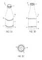
- FIG. 3Ais an overhead front view of another exemplary container for conveying or handling by the system and method according to various embodiments of the present invention
- FIG. 3Bis a side view of the container in FIG. 3A ;
- FIG. 3Cis a bottom view of the container in FIG. 3A ;
- FIG. 4is a side view of yet another exemplary container, with a cap, for conveying or handling by the system and method according to various embodiments of the present invention
- FIG. 5Ais a representation of conveying or handling a plurality of filled and capped containers substantially similar to the container in FIG. 2A according to various embodiments of the present invention
- FIG. 5Bis a representation of conveying or handling a plurality of filled, capped, and cooled containers substantially similar to the container in FIG. 2A according to various embodiments of the present invention
- FIG. 6Ais a representation of conveying or handling a plurality of filled and capped containers substantially similar to the container in FIG. 3A according to various embodiments of the present invention
- FIG. 6Bis a representation of conveying or handling a plurality of filled, capped, and cooled containers substantially similar to the container in FIG. 3A according to various embodiments of the present invention
- FIG. 7shows a grouping of containers being conveyed or handled according to various embodiments of the present invention.
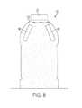
- FIG. 8is a side view of yet another exemplary container having a plurality of supplemental temporary vacuum panels according to various embodiments of the present invention.
- FIG. 9Ais a cross section showing a base portion of a container according to various embodiments of the present invention having an un-activated moveable element.
- FIG. 9Bis a cross section showing a base portion of a container according to various embodiments of the present invention having an activated moveable element.
- aspects of the present inventionare directed to a problem encountered during conveyance of hot-filled and capped containers after cooling, but prior to base activation of the containers.
- the probleminvolves relief for temporary deformation of the containers (e.g., in the container sidewalls) caused by vacuums induced in the filled and sealed containers as a result of cooling the hot product.
- the vacuumsmay cause the containers to contract to an oval or other temporarily deformed shape.
- Such temporary deformationscan cause reliability problems in conveying or transporting the containers, as the temporary deformations may provide unstable support points between adjacent, touching containers. As a result, speed, efficiency, and reliability conveyance and handling may deteriorate.
- embodiments of the present inventionprovide for stable touch points for the containers by providing annular portions to confine the temporary deformation to a predetermined smooth sidewall portion, while preventing distortion of portions of the container that contact other containers during conveyance or handling.
- Alternative embodiments of the present inventionprovide for stable touch points for the containers during conveyance prior to activation by directing the temporary deformation to one or more temporary vacuum panels that temporarily compensate for the vacuum until the vacuum is permanently removed or reduced by activating.
- FIG. 1is a flow chart representation of a method 100 according to various embodiments of the present invention.
- Method 100can be any suitable method.
- method 100can be for conveying or handling a plurality of filled containers, such as hot-tilled plastic bottles.
- Method 100can start at S 102 and proceed to any suitable step or operation. In various embodiments, the method can proceed to S 104 .
- S 104can be any suitable step or operation.
- S 104can represent forming a container or containers.
- the containerscan be formed by any suitable manner and by any suitable means.
- the containerscan be blow molded or injection blow molded using, for example, a rotary blow molding apparatus.
- the containerscan be made of any suitable material.
- the containerscan be made of plastic materials known in the art.
- the containersmay have, for example, a one-piece construction and can be prepared from a monolayer plastic material, such as a polyamide (e.g., nylon); a polyolefin such as polyethylene (e.g., low density polyethylene (LDPE), high density polyethylene (HDPE)) or polypropylene; a polyester (e.g., polyethylene terephthalate (PET), polyethylene naphtalate (PEN)); or others, which can also include additives to vary the physical or chemical properties of the material.
- the containerscan be prepared from a multilayer plastic material.
- the layerscan be any plastic material, including virgin, recycled and reground material, and can include plastics or other materials with additives to improve physical properties of the container.
- plastics or other materials with additives to improve physical properties of the containerinclude, for example, ethylvinyl alcohol (EVOH) and tie layers or hinders to hold together materials that are subject to delamination when used in adjacent layers.
- EVOHethylvinyl alcohol
- a coatingmay be applied over the monolayer or multilayer material, for example to introduce oxygen barrier properties.
- the containerscan be formed to have any suitable shape and configuration.
- the containersmay be formed (e.g., by blow molding) with an approximately polygonal, circular or oval projection extending, for example, from a bottom end of a base portion of the container.
- this projectioncan be a moveable element, such as, but not limited to, a vacuum panel.
- a projectionmay project from the shoulders of the container, or from another area of the container. If the projection extends from the bottom end of the base portion of the container, before the container exits the forming operation, the projection may be inverted or moved inside the container to make the base surface of the blow-molded container relatively flat so the container can be conveyed on a table top.
- FIGS. 2-4show examples of containers that can be formed at forming step S 104 .
- the containers 20 , 30 , 40 shown in FIGS. 2-4are shown in their respective configurations after the forming step.
- the containers 20 , 30 , 40 shown in FIGS. 2-4are shown after exiting a blow molding operation.
- the containers shown in FIGS. 2-4are generally cylindrical along a central longitudinal axis.
- the containers used in the method and system according to various embodimentsare not limited to being cylindrical and can be any suitable shape, such as generally rectangular, oval, or triangular along a central longitudinal axis.
- FIG. 2is comprised of FIGS. 2A-2C , FIGS. 2A-2C respectively correspond to an exemplary embodiment of a container 20 conveyed or handled by various embodiments of the method and system of the present invention.
- the container 20 shown in FIGS. 2A and 2Bcan include a neck portion 22 , a body portion 23 , and a base portion 25 defining an inner volume.
- Neck portion 22can be of any suitable configuration.
- neck portion 22can be configured to allow a cap or lid (not shown) to be coupled thereto to seal the container.
- the cap or lidcan be removably coupled to the neck portion 22 by any suitable means, such as threads, snap-fitted, etc.
- Neck portion 22also may have a lip having a greater diameter than the general overall diameter of the part of the neck portion 22 that receives the cap or lid, wherein the lip may be arranged such that one side abuts the end of the cap or lid (including frangible “tamper rings”), and such that the other side is used as a support for rail conveyance systems, for example.
- the neck portion 22can be sized to allow a spout of a filling apparatus or machine to be positioned adjacent or slightly into the inner volume thereof to fill the container 20 with a product.
- Body portion 23can be of any suitable configuration.
- body portion 23can be configured substantially as shown in FIGS. 2A and 2B , with a portion that tapers outward from neck portion 22 (e.g., forming a generally conical bell section), a first annular portion 26 , a sidewall portion 24 , and a second annular portion 27 .
- the first annular portion 26 and the second annular portion 27can be of any suitable configuration, shape, or size. In various embodiments, the first annular portion 26 and the second annular portion 27 can be rounded. Optionally, the first and second annular portions can be concave hoop rings. As to size, the annular portions 26 , 27 can be between 3 mm to 5 mm tall and 2 mm to 4 mm deep, for example. Generally the first and second annular portions 26 , 27 are the same shape and size. Optionally, the annular portions can be different in size and/or shape. For example, a deeper first annular portion 26 can be used, with dimensions such as 5 mm to 15 mm tall and 5 mm to 8 mm deep.
- the second annular portion 27may have larger dimensions than the first annular portion 26 .
- the container 20can have a part of the body portion 23 above the first annular portion 26 that is greater in diameter than the first annular portion 26 and the second annular portion 27 . This part may be sized to contact one or more adjacent containers during conveyance and handling of the containers. For example, after a cooling operation or process, the part of the body portion 23 above the first annular portion 26 greater in diameter than the first annular portion may contact substantially similar parts on one or more other containers, thereby providing a stable contact or touch point for conveyance.
- the first annular portion 26 and the second annular portion 27can be located at any suitable place along the body portion 23 in relation to one another or to another portion of the container 20 .
- the annular portions 26 , 27are at opposite sides of sidewall portion 24 , with the first annular portion 26 being located above the sidewall portion 24 and the second annular portion 27 being located below the sidewall portion 24 .
- the containercan have any suitable number of annular portions, such as one, two, three, etc.
- the sidewall portion 24can be of any suitable shape or configuration.
- the sidewall portion 24 shown in FIGS. 2A and 2Bcan be smooth and cylindrical.
- the sidewall portion 24is free of any vacuum panels, such as supplemental or mini vacuum panels.
- sidewall portion 24also can be free of any additional features, such as grips, ribs, etc.
- the sidewall portion 24can be “waisted” in (such that the shape is convex).
- first annular portion 26 and second annular portion 27can be arranged at any suitable position of body portion 23 .
- first annular portion 26 and second annular portion 27can be spaced apart from one another by sidewall portion 24 , such that the sidewall portion 24 is capable of deforming or distorting, while the annular portions and areas above and below the first and second annular portions, respectively, substantially maintain their shape or substantially resist deformation or distortion.
- the first annular portion 26 and the second annular portion 27may be configured to create substantially stable contact points above and below a portion of the container that deforms or distorts, such as the sidewall portion 24 .
- annular portions 26 , 27 and flexible sidewall portion 24may allow the sidewall portion 24 of the container 20 to be free of structural geometry when using an offsetting pressure mechanism after hot filling and cooling the container, such as inverting a moveable element.
- Base portion 25can be of any suitable configuration.
- base portion 25can be generally cylindrical, rectangular, or triangular about a central longitudinal axis.
- the base portion 25 shown in FIG. 2for example, is cylindrical.
- base portion 25can have one end coupled to second annular portion 27 and another end thereof forming a standing surface upon to support the container 20 on a substantially fiat surface.
- the part of the base portion 25 coupled to the second annular portion 27can have a diameter greater than a diameter of the second annular portion 27 and the first annular portion 26 .
- the diameter of the part of the base portion 25 coupled to the second annular portion 27can have substantially the same diameter as the part of the body portion 23 immediately above the first annular portion 26 .
- This part of the base portion 25may be sized to contact one or more adjacent containers during conveyance and handling of the containers. For example, after a cooling operation or process, the part of the base portion 25 below the second annular portion 27 greater in diameter may contact substantially similar parts on one or more other containers, thereby providing a stable contact or touch point for conveyance.
- base portion 25also may have a moveable element formed in a bottom end thereof.
- FIG. 2Cshows an exemplary moveable element 28 according to various embodiments of the present invention.
- the moveable element 28can initially be formed (e.g., blow molded) to project below the standing surface of the container 20 , and prior to exiting or immediately after exiting the forming operation, the moveable element 28 initially projecting below the standing surface can be moved or manipulated such that it is entirely above the standing surface of the container for operations or steps after leaving the forming step or operation.
- the moveable element 28can be moved above the standing surface of the container so the standing surface of the container can provide a stable surface for supporting the container of a substantially flat surface, for example.
- Moveable element 28can be of any suitable configuration.
- moveable element 28can have creases 29 , which can facilitate repositioning or inverting of the moveable element 28 .
- the moveable element 28may be configured to be moved from a first position to a second position. In various embodiments, such movement is called activating or activation.
- the moveable element 28can be configured such that in the first position, at least a substantially planar portion of the moveable element is at an outwardly inclined position with respect to the interior of the container 20 , and such that in the second position, at least a substantially planar portion thereof is at an inwardly inclined position.
- the substantially planar portion for the outwardly inclined positionis the same as the substantially planar portion for the inwardly inclined position.
- the moveable element 28can be configured substantially permanently to compensate for vacuum forces created by cooling the containers.
- substantially permanently compensatingmay mean removing a portion of the vacuum until the container is opened by a consumer, for example.
- a portion of the vacuummay can some of the vacuum, all of the vacuum, or an of the vacuum plus providing a positive pressure.
- Moveable element 28also may have an anti-inverting portion.
- the anti-inverting portionmay be configured to move with the portion of the moveable element that moves from an outwardly inclined position to an inwardly inclined position. Note, however, that the anti-inverting portion may be generally inwardly inclined at both of the foregoing positions.
- FIG. 3which is comprised of FIGS. 3A-3C , illustrate another exemplary embodiment of a container 30 conveyed or handled by various embodiments of the method and system of the present invention.
- the container 30 shown in FIGS. 3A and 3Bcan include a neck portion 32 , a body portion 33 , and a base portion 35 defining an inner volume.
- Neck portion 32can be of any suitable configuration. In various embodiments, the neck portion 32 is substantially the same as that described above for FIG. 2 . Note that the diameter for the opening of the neck portion 32 may or may not be the same as that of FIG. 2 .
- Body portion 33can be of any suitable configuration.
- body portion 33can be configured substantially as shown in FIGS. 3A and 3B , with a portion that tapers outward from neck portion 32 (e.g., forming a generally conical bell section), a first annular portion 36 , a sidewall portion 34 , and a second annular portion 37 .
- the tapering portione.g., bell portion from neck to first annular portion 36
- the tapering portioncan also include a two-step conical section to form the shape of a long neck style container.
- the first annular portion 36 and the second annular portion 37can be of any suitable configuration, shape, or size. In various embodiments, the first annular portion 36 and the second annular portion 37 can be rounded. Optionally, the first and second annular portions can be concave hoop rings. As to size, the annular portions 36 , 37 can be between 3 mm to 5 mm tali and 2 mm to 4 mm deep. Generally the first and second annular portions 36 , 37 are the same shape and size. Optionally, the annular portions can be different in size and/or shape. For example, a deeper first annular portion 36 can be used, with dimensions of 5 mm to 15 mm tall and 5 mm to 8 mm deep, for example.
- the second annular portion 37may have larger dimensions than the first annular portion 36 .
- the container 30can have a part of the body portion 33 above the first annular portion 36 that is greater in diameter than the first annular portion 36 and the second annular portion 37 .
- This partmay be sized to contact one or more adjacent containers during conveyance and handling of the containers.
- the part of the body portion 33 above the first annular portion 36 greater in diametermay contact substantially similar parts on one or more other containers, thereby providing a substantially stable contact or touch point for conveyance.
- one or both of the first annular portion 36 and the second annular portion 37may comprise the part of the body portion 33 that contacts corresponding parts of adjacent container as the containers are conveyed or handled.
- the first annular portion 36 and the second annular portion 37can be located at any suitable place along the body portion 33 in relation to one another or to another portion of the container 30 .
- the annular portions 36 , 37are at opposite sides of sidewall portion 34 , with the first annular portion 36 being located above the sidewall portion 34 and the second annular portion 37 being located below the sidewall portion 34 .
- the containercan have any suitable number of annular portions, such as one, two, three, etc.
- the sidewall portion 34can be of any suitable shape or configuration.
- the sidewall portion 34 shown in FIGS. 3A and 3Bcan be smooth and cylindrical. Note that the sidewall portion 34 may be shorter than the sidewall portion 24 in FIGS. 2A and 2B .
- the sidewall portion 34is free of any vacuum panels, such as supplemental or mini vacuum panels.
- the sidewall portion 34can be free of any additional elements, such as ribs, grips, etc.
- the sidewall portion 34can be “waisted” in (such that the shape is convex).
- first annular portion 36 and second annular portion 37can be arranged at any suitable position of body portion 33 .
- first annular portion 36 and second annular portion 37are spaced apart from one another by sidewall portion 34 , such that the sidewall portion 34 is capable of deforming or distorting, while the areas above and below the first and second annular portions, respectively, substantially maintain their shape or substantially resist deformation or distortion.
- the first annular portion 36 and the second annular portion 37may be configured to create substantially stable contact points above and below a portion of the container that deforms or distorts, such as the sidewall portion 34 .
- annular portions 36 , 37 and flexible sidewall portion 34may allow the sidewall portion 34 of the container 30 to be free of structural geometry when using an offsetting pressure mechanism after hot filling and cooling the container, such as inverting a vacuum panel.
- Base portion 35can be of any suitable configuration.
- base portion 35can be generally cylindrical, rectangular, or triangular about a central longitudinal axis.
- the base portion 35 shown in FIG. 3for example, is cylindrical.
- base portion 35can have one end coupled to second annular portion 37 and another end thereof forming a standing surface upon to support the container 30 on a substantially flat surface.
- the part of the base portion 35 coupled to the second annular portion 37can have a diameter greater than a diameter of the second annular portion 37 and the first annular portion 36 .
- the diameter of the part of the base portion 35 coupled to the second annular portion 37can have substantially the same diameter as the part of the body portion 33 immediately above the first annular portion 36 .
- This part of the base portion 35may be sized to contact one or more adjacent containers during conveyance and handling of the containers.
- the part of the base portion 35 below the second annular portion 37 greater in diametermay contact substantially similar parts on one or more other containers, thereby providing a stable contact or touch point for conveyance.
- one or more of the annular portions 36 , 37can comprise the stable contact or touch points.
- base portion 35also may have a moveable element formed in a bottom end thereof.
- FIG. 3Cshows an exemplary moveable element 38 according to various embodiments of the present invention.
- the moveable element 38may be substantially the same as that described for FIG. 2 above. Note that the diameter of the base portion 35 may or may not be the same. Therefore, the moveable element 38 in FIG. 3C may differ from that of FIG. 2 in this respect.
- moveable element 38 for the container shown in FIG. 3can be configured such that in the first position, at least a substantially planar portion of the moveable element is at an outwardly inclined position with respect to the interior of the container 30 , and such that in the second position, at least a substantially planar portion thereof is at an inwardly inclined position.
- the substantially planar portion for the outwardly inclined positionis the same as the substantially planar portion for the inwardly inclined position.
- the moveable element 38can be configured substantially permanently to compensate for vacuum forces created by cooling the containers, in various embodiments, substantially permanently compensating may mean removing a portion of the vacuum until the container is opened by a consumer, for example.
- a portion of the vacuummay mean some of the vacuum, all of the vacuum, or all of the vacuum plus providing a positive pressure.
- Moveable element 38also may have an anti-inverting portion.
- the anti-inverting portionis configured to move with the portion of the moveable element that moves from an outwardly inclined position to an inwardly inclined position. Note, however, that the anti-inverting portion may be generally inwardly inclined for both of the aforementioned positions.
- FIG. 4shows yet another exemplary embodiment of a container 40 conveyed or handled by various embodiments of the method and system of the present invention.
- the container 40 in FIG. 4can have a neck portion 42 , a body portion 43 , and abuse portion 45 defining an inner volume.
- the body portion 43can include a substantially smooth sidewall 44 , a first annular portion 46 , and a second annular portion 47 .
- the container 40 shown in FIG. 4also is shown with a cap 41 coupled to neck portion 42 .
- Cap 41can be coupled to neck portion 42 by any suitable means, such as threads, snap connections, etc.
- the smooth sidewall 44 shown in FIG. 4tapers outward from its top to its bottom.
- the smooth sidewall 44may taper inward from its top to its bottom.
- the annular portions 46 , 47may be substantially the same in functionality as those discussed above for FIGS. 2 and 3 .
- the annular portions 46 , 47can be configured to provide one or more substantially stable touch points for conveyance and handling of the container 40 in contact with other adjacent containers in various operations of a production line, such as after cooling the containers and before activating the containers.
- Annular portions 46 , 47also can be configured to confine distortion or deformation of the container due to hot-filling and/or cooling operations to the smooth sidewall 44 , for example. Note that in this embodiment, only the portion of the container 40 above the annular portion 46 may have a diameter greater than the smooth sidewall 44 .
- only the rounded portion above the first annular portion 46may serve as a substantially stable touch or contact point for conveying or handling with other containers.
- the base portion 45may be designed such that it has a diameter greater than the smooth sidewall 44 to serve as a substantially stable touch or contact point for conveying or handling with other containers.
- a base portion 45 with a diameter greater than the smooth sidewall 44can serve as the only touch or contact point for conveying or handling with other containers.
- container 40can have a moveable member incorporated into the bottom end of the base portion 45 . The moveable member can be substantially the same as described above for FIGS. 2 and 3 .
- FIGS. 2-4are representative only and not meant to limit the scope of the type or configuration of containers capable of being conveyed or handled by the method and system according to various embodiments of the present invention.
- the method 100can proceed to any suitable step or operation. In various embodiments, the method 100 can proceed to S 106 .
- the containerscan be filled with a product.
- the containercan be moved or conveyed to a filling station by any suitable means or combination of means, such as palletized and shipped, a conveyor belt, a rotary apparatus, and/or feed screws.
- a filling stationby any suitable means or combination of means, such as palletized and shipped, a conveyor belt, a rotary apparatus, and/or feed screws.
- one or more of the annular portionscan provide for substantially stable touch points. That is to say, before and during the filling, the containers can be in touching relationship with at least one other container, with the annular portions providing substantially stable touch points for stability during conveyance and handling.
- the productcan be filled using any suitable means, such as a filling station configured with a spout or spouts moveable to be positioned adjacent or slightly interior a top opening of the container, or adjacent or slightly interior respective top openings of containers in the case of multiple spouts. Moreover, containers can be filled successively, one at a time, or a group of containers can be filled substantially simultaneous.
- the productcan be any suitable product including, but not limited to, carbonated beverages, non-Carbonated beverages, water, tea, sports drinks dry products, etc.
- the productcan be filled at an elevated temperature. For example, the product can be filled at a temperature of approximately 185 degrees Fahrenheit (85 degrees Celsius).
- the moveable elementcan extend to the standing surface of the container, but not below it.
- the moveable elementcan be entirely above the standing surface.
- the method 100can proceed to any suitable step or operation.
- the method 100may proceed to S 108 .
- the containersmay be capped.
- the containerscan be capped by any suitable means, such as a mechanical apparatus that positions a cap or lid over each of the containers and appropriately couples the cap or lid to the neck portion of the container.
- the containerscan be capped successively, one at a time, or a group of containers can be capped substantially simultaneous.
- the capping meanscan couple the cap or lid to the neck portion of the container based on the means by which the cap or lid and neck are configured. For example, for threaded caps and neck portions, the capping means may move the cap such that the cap engages the threads of the neck.
- one or more of the annular portionscan provide for substantially stable touch points. That is to say, before and during the capping, the containers can be in touching relationship with at least one other container, with the annular portions providing substantially stable touch points for stability during this portion of the conveyance and handling of the containers. Additionally, the capping operation may create a substantially air-tight seal. In various embodiments, the filling an elevated temperature and capping may create an overpressure within the container causing a portion of the container to distort or deform. In various embodiments, the first and second annular portions of the container can be configured to direct or confine the distortion or deformation to a smooth sidewall portion arranged therebetween. The deformation may be such that the smooth sidewall bows outward.
- the containercan be configured such that, in bowing outward, the smooth sidewall does not extend to an outer diameter of one or more portions of the container above and/or below the annular portions.
- the annular portionscan confine the deformation to the smooth sidewall and can provide for substantially stable touch points outside of the smooth sidewall for contact with touch points of other, adjacent containers.
- the deformation of the containerscan be unpredictable in shape, size, and timing.
- the deformationcan be different in shape, size, and timing from container to container.
- the moveable elementcan extend to the standing surface of the container, but not below it.
- the moveable elementcan be entirely above the standing surface.
- the method 100can proceed to any suitable step or operation. In various embodiments, the method 100 may proceed to S 110 .
- a vacuumcan be created in the filled and capped container.
- the vacuumcan be created by any suitable means, such as by cooling.
- a containercan be cooled from about or around 185 degrees Fahrenheit to about or around 100 degrees Fahrenheit. Cooling, for example, can be performed by any suitable means, such as a traditional cooler, which may have ambient air or coolant blowing against the hot-filled containers to cool their contents to room temperature.
- the filled and capped containersmay be passed through a tunnel in which a fluid, such as water, may be sprayed in a shower-like fashion to cool the container.
- the fluidcan be at any suitable temperature for cooling the product in the container.
- the fluidcan be at room temperature.
- the fluidcan be at a temperature colder than room temperature.
- room temperatureis not limited to being at or between the aforementioned temperatures, and can be any suitable temperature designated as room temperature.
- a temperature lower than room temperaturemay be, for example, about or around 75 degrees Fahrenheit to about or around 65 degrees Fahrenheit.
- the temperature below room temperaturecan be any suitable temperature designated as below room temperature.
- a vacuum created in the container by cooling or otherwiseis based on a change in temperature from at or around the hot-filled temperature discussed above to at or around room temperature or below room temperature, as discussed above.
- the present inventiondoes not contemplate vacuums of magnitude substantially outside the range created based on the aforementioned ranges of change in temperature, such as “infinite” vacuums.
- the vacuumcan cause distortion or deformation, such as roll out, “ovalization,” “triangularization,” etc.
- the distortion or deformationcan be unpredictable in shape, size, and timing.
- the deformation or distortioncan be different in shape, size, and timing, as well as unpredictable.
- typically the deformation or distortionis temporary.
- the temporary deformation or distortioncan be directed to a predetermined specified portion of the container.
- containermay be configured with annular portions, and the temporary deformation can be directed substantially to the smooth sidewall of the container, with substantially no deformation of the annular portions or of portions of the container above an upper annular portion or below a lower annular portion.
- the temporary deformationcan be substantially confined to the smooth sidewall portion of the containers, with the annular portions substantially resisting deformation or distortion.
- the annular portionscan also provide for respective substantially stable touch or contact points for contact with corresponding substantially stable touch points of other adjacent containers throughout or at various portions of conveying and handling.
- a substantially stable touch pointcan be located above the annular portion, and for a lower annular portion, a substantially stable touch point can be located below this annular portion, on a base portion of the container.
- a portion of the annular portioncan comprise the substantially stable touch or contact point.
- the temporary deformation caused by a vacuum induced by coolingcan be directed to one or more supplemental vacuum panels.
- FIG. 8shows a configuration of a capped and filled container 20 having supplemental vacuum panels 80 .
- the one or more supplemental vacuum panels 80can temporarily compensate for the vacuum while conveying or handling containers prior to activation of a moveable element in the bottom end of a base portion to permanently remove the vacuum.
- the container in FIG. 8shows upper and lower “indentations” separated by a substantially smooth sidewall portion. These indentions may or may not be first and second annular portions substantially as described herein.
- alternative container embodimentsare intended to provide temporary distortion or deformation compensation using only the one or more supplemental vacuum panels 80 or the one or more supplemental vacuum panels 80 in combination with annular portions that provide for substantially stable touch points.
- the one or more supplemental vacuum panels 80can also provide for one or more substantially stable touch points since temporary distortion or deformation is substantially confined thereto.
- the moveable elementcan extend to the standing surface of the container, but not below it.
- the moveable elementcan be entirely above the standing surface.
- the containerscan have a vacuum induced therein in any suitable grouping or order.
- containerscan be passed through a cooling means in single file, with one or more substantially stable touch points of adjacent containers being in contact with corresponding one or more substantially stable touch points.
- the containerscan be passed through a cooling means in a matrix or randomly grouped configuration, with at least one “inner” container and a plurality of “outer” containers.
- Adjacent containerscan have one or more substantially stable touch points in contact with corresponding one or more substantially stable touch points.
- inner containermay cool slower than outer containers.
- the temporary deformation for inner containersmay be different and/or unpredictable in shape, size, and time from the temporary deformation for outer containers. Of course, none, some, or all of the temporary deformations may be the same.
- Containerscan be conveyed or handled before, during, and after the vacuum creating step S 110 by any suitable means, such as a conveyor belt.
- the method 100can proceed to any suitable step or operation. In various embodiments, the method 100 may proceed to S 112 .
- S 112can represent conveying or handling the containers.
- the containerscan be handled or conveyed by any suitable means.
- the containerscan be handled or conveyed by a conveyor belt.
- the containers being conveyedcan have vacuums created therein, and the containers can be temporarily deformed or distorted based on the vacuums.
- the deformationmay be confined or directed to a predetermined portion of the container, such as a smooth sidewall or a supplemental vacuum panel. From container to container, the temporary deformations may be different and/or unpredictable in shape, size, and time from the temporary deformation for outer containers.
- the containers having temporary deformationscan be conveyed such that each container is in contact with a plurality of other containers.
- the annular portionscan provide for one or more substantially stable touch points for conveyance or handling of the containers.
- one or more of the annular portionsmay comprise the one or more substantially stable touch points.
- one or more supplemental vacuum panelsmay provide for one or more substantially stable touch points.
- the containers with temporary deformationscan be conveyed or handled in any suitable grouping or order.
- containers with temporary deformationscan be conveyed in single file, with one or more substantially stable touch points of adjacent containers being in contact with corresponding one or more substantially stable touch points.
- the containers with temporary deformationscan be conveyed in a matrix or randomly grouped configuration, with at least one “inner” container and a plurality of “outer” containers.
- Adjacent containerscan have one or more substantially stable touch points in contact with corresponding one or more substantially stable touch points.
- the one or substantially stable touch pointscan be facilitated by associated annular portions or temporary supplemental vacuum panels.
- the moveable elementcan extend to the standing surface of the container, but not below it.
- the moveable elementcan be entirely above the standing surface.
- the containersmay be palletized, wherein the annular portions can provide support and stabilization to a plurality of palletized containers.
- the method 100can proceed to any suitable step or operation. In various embodiments, the method 100 may proceed to S 114 .
- S 114can represent reducing, eliminating, or countering a portion of the vacuum in the container.
- the reduction of a portion of the vacuum in the containercan also reduce or eliminate the temporary deformation or distortion of the container.
- the containercan be returned substantially to its pre-filled or pre-cooled form.
- the vacuums in the containerscan be reduced by any suitable means. For example, for a container configured with a moveable element arranged in the bottom end thereof, the moveable element can be moved or activated to remove the vacuum. In various embodiments, for activation, the moveable element can be moved from a first position to a second position, wherein the second position is more toward the interior of the container than the first position. Additionally, some or all of the moveable element can be moved.
- the first positioncan include at least a portion of the moveable member being at an outwardly inclined position
- the second positioncan include at least a portion of the moveable member being at an inwardly inclined position. Movement of the moveable element to activate the container may be called inverting or inversion of the moveable element.
- the movement of the moveable elementcan reduce or eliminate a portion of the vacuum
- the portion of the vacuum removed or reducedis the entire vacuum.
- the portion of the vacuum removed or reducedcan mean that the entire vacuum is removed and a positive pressure is created within the container.
- the portion of the vacuum reduced or eliminatedmay be less than the entire vacuum.
- the remainder of the vacuumcan be removed or reduced by one or more supplemental or mini vacuum panels.
- the supplemental vacuum panels referred to herecan substantially permanently remove or reduce the remaining portion of the vacuum not removed by the moveable element.
- the moveable elementcan be moved (or activated or inverted) by any suitable means, such as mechanical or pneumatic means.
- a push rodcan be actuated to force the moveable element from the aforementioned first position to the second position.
- the moveable element of the containerbefore, during, and after the reducing a portion of the vacuum in the container, the moveable element of the container is above the standing surface at all times.
- the moveable elementmay be at or above the standing surface at all times.
- the methodcan proceed to any suitable step or operation.
- FIG. 1shows the method ending at S 116 .
- the containerscan proceed to any suitable process or operation.
- the containerscan next proceed to a testing or quality assurance operation, to a labeling operation, to a packaging operation for storage and/or shipment, and/or to a storage or staving operation.
- FIGS. 5A and 5Brepresent conveying or handling a plurality of filled and capped containers substantially similar to the container in FIG. 2A .
- FIG. 5Acan represent the filled and capped containers before a vacuum is induced, for example, by cooling.
- the containerscan be conveyed on a conveyor belt 50 , for example, and FIG. 5A shows movement from left to right on the page.
- the three dotsmay represent that more containers can be arranged in either direction.
- FIG. 5(both A and B) can represent conveying in single file or in a matrix (with containers behind containers 20 being hidden from view).
- Item 53can represent a fill line of the product, and the fill line can be at any suitable position, based on container configuration, hot-fill temperature, cooling temperature, cooling rate, etc.
- the fill height 53is substantially the same between FIGS. 5A and 5B .
- the fill heightscan be different from FIGS. 5A and 513 , as well as between containers in FIG. 5B , due to deformations experienced by the containers caused by induced vacuums.
- annular portions 26 of the containerscan provide for substantially stable touch or contact points 55 for adjacent containers.
- annular portions 27can provide for substantially stable touch or contact points 57 for adjacent containers.
- Such stable touch points 55 , 57can prevent from contacting other, adjacent containers any temporary deformation of the smooth sidewalls 24 due to overpressure caused by elevated temperatures. As a result, the containers more reliably can be conveyed or handled. This can lead to speed improvements for conveyance and/or handling.
- FIG. 5Bcan represent conveyance and handling of the containers 20 during and/or after creating a vacuum in the containers by cooling, for example.
- the smooth sidewalls 24can become temporarily distorted or deformed in response to the vacuums.
- smooth sidewalls 24can temporarily distort from a position 24 a to a position 24 b .
- the temporary distortion or deformationcan be unpredictable in size, shape, and time.
- FIG. 5Bshows all of the deformations as substantially the same for each of the containers, the deformations from container 20 to container 20 may be different in size, shape, and time.
- annular portions 26 of the containersalso can provide for substantially stable touch or contact points 55 for adjacent containers having temporary deformations.
- annular portions 27can provide for substantially stable touch or contact points 57 for adjacent containers having temporary deformations.
- Such stable touch points 55 , 57can prevent from contacting other, adjacent containers any temporary deformation of the smooth sidewalls 24 due to vacuums created in the containers. As a result, the containers with temporary deformations more reliably can be conveyed or handled. This can lead to speed improvements for conveyance and/or handling.
- FIGS. 6A and 6B representationconveying or handling a plurality of filled and capped containers substantially similar to the container in FIG. 3A . These containers are conveyed or handled substantially the same as described above for FIG. 5 . In the representation in FIG. 6 , however, the touch points may not be arranged or located at the same or similar parts of the containers 30 . As with FIGS. 5A and 5B , the fill height 63 is shown as being substantially the same between FIGS. 6A and 6B . However, the fill heights can be different from FIGS. 6A and 6B , as well as between containers in FIG. 6B , due to deformations experienced by the containers caused by induced vacuums.
- FIG. 7shows a representation of a plurality of containers arranged in a matrix.
- the matrixcan be any suitable size, with any suitable number of rows and columns, such as a one-by-one matrix, a one-by-three matrix, or a three-by-three matrix.
- the representation in FIG. 7can represent a situation where the containers are filled and capped and being conveyed with a positive pressure temporary deformation, or a situation where the containers have been filled, capped, and cooled, the temporary deformations caused by vacuums in the containers 20 . In either case, the containers 20 can be conveyed such that substantially stable contact or touch points 55 are maintained.
- the substantially stable touch points 55can be provided for by one or more annular portions.
- the one or more substantially stable touch points 55can be provided for by one or more supplemental temporary vacuum panels.
- FIGS. 9A and 9Bshow a cross section of a filled, sealed, and cooled container 20 with a moveable element 28 prior to activation ( FIG. 9A ) and after activation ( FIG. 9B ). Note that any temporary deformation of the smooth sidewall 24 prior to activation has been omitted in this figure.
- base portion 25can include a standing surface 90
- moveable element 28can include a moveable portion 92 and an anti-inverting portion 94 .
- the moveable element 28 in FIG. 9Ais shown entirely above standing surface 90 .
- moveable element 28can be at or above standing surface 90 .
- moveable portion 92can be at an outwardly inclined position with respect to the inner volume of the container 20 .
- FIG. 9Bshows moveable element 28 in an activated state.
- moveable portion 92moves from the outwardly inclined position to an inwardly inclined position, which can be called inversion of the moveable portion 92 .
- Anti-inverting portion 94substantially retains its shape and arrangement for activation, but can move upward and inward toward the inner volume of the container.
- activating the moveable element 28can remove a portion of the vacuum. In various embodiments, removing a portion of the vacuum can return the container to its pre-filled or pre-cooled configuration.
Landscapes
- Engineering & Computer Science (AREA)
- Mechanical Engineering (AREA)
- Ceramic Engineering (AREA)
- Containers Having Bodies Formed In One Piece (AREA)
- Filling Of Jars Or Cans And Processes For Cleaning And Sealing Jars (AREA)
- Blow-Moulding Or Thermoforming Of Plastics Or The Like (AREA)
- Rigid Containers With Two Or More Constituent Elements (AREA)
Abstract
Description
Claims (20)
Priority Applications (1)
| Application Number | Priority Date | Filing Date | Title |
|---|---|---|---|
| US13/450,872US8429880B2 (en) | 2009-01-06 | 2012-04-19 | System for filling, capping, cooling and handling containers |
Applications Claiming Priority (3)
| Application Number | Priority Date | Filing Date | Title |
|---|---|---|---|
| US12/349,268US7926243B2 (en) | 2009-01-06 | 2009-01-06 | Method and system for handling containers |
| US13/087,472US8171701B2 (en) | 2009-01-06 | 2011-04-15 | Method and system for handling containers |
| US13/450,872US8429880B2 (en) | 2009-01-06 | 2012-04-19 | System for filling, capping, cooling and handling containers |
Related Parent Applications (1)
| Application Number | Title | Priority Date | Filing Date |
|---|---|---|---|
| US13/087,472ContinuationUS8171701B2 (en) | 2009-01-06 | 2011-04-15 | Method and system for handling containers |
Publications (2)
| Publication Number | Publication Date |
|---|---|
| US20120240515A1 US20120240515A1 (en) | 2012-09-27 |
| US8429880B2true US8429880B2 (en) | 2013-04-30 |
Family
ID=42310801
Family Applications (5)
| Application Number | Title | Priority Date | Filing Date |
|---|---|---|---|
| US12/349,268Active2029-06-07US7926243B2 (en) | 2009-01-06 | 2009-01-06 | Method and system for handling containers |
| US12/651,461Active2029-03-09US8096098B2 (en) | 2009-01-06 | 2010-01-02 | Method and system for handling containers |
| US13/087,472ActiveUS8171701B2 (en) | 2009-01-06 | 2011-04-15 | Method and system for handling containers |
| US13/184,368ActiveUS10035690B2 (en) | 2009-01-06 | 2011-07-15 | Deformable container with hoop rings |
| US13/450,872ActiveUS8429880B2 (en) | 2009-01-06 | 2012-04-19 | System for filling, capping, cooling and handling containers |
Family Applications Before (4)
| Application Number | Title | Priority Date | Filing Date |
|---|---|---|---|
| US12/349,268Active2029-06-07US7926243B2 (en) | 2009-01-06 | 2009-01-06 | Method and system for handling containers |
| US12/651,461Active2029-03-09US8096098B2 (en) | 2009-01-06 | 2010-01-02 | Method and system for handling containers |
| US13/087,472ActiveUS8171701B2 (en) | 2009-01-06 | 2011-04-15 | Method and system for handling containers |
| US13/184,368ActiveUS10035690B2 (en) | 2009-01-06 | 2011-07-15 | Deformable container with hoop rings |
Country Status (11)
| Country | Link |
|---|---|
| US (5) | US7926243B2 (en) |
| EP (1) | EP2389329B1 (en) |
| JP (1) | JP5619771B2 (en) |
| AU (1) | AU2010203790A1 (en) |
| BR (1) | BRPI1007385A2 (en) |
| CA (2) | CA2748184C (en) |
| ES (1) | ES2539328T3 (en) |
| MX (1) | MX2011007233A (en) |
| NZ (1) | NZ593486A (en) |
| PL (1) | PL2389329T3 (en) |
| WO (1) | WO2010080731A1 (en) |
Cited By (6)
| Publication number | Priority date | Publication date | Assignee | Title |
|---|---|---|---|---|
| US20120012592A1 (en)* | 2010-07-16 | 2012-01-19 | George David Lisch | Controlled base flash forming a standing ring |
| US9463900B2 (en)* | 2010-09-30 | 2016-10-11 | Yoshino Kogyosho Co., Ltd. | Bottle made from synthetic resin material and formed in a cylindrical shape having a bottom portion |
| DE202015106723U1 (en)* | 2015-12-10 | 2017-03-13 | Krones Ag | Labeling machine for plastic containers |
| US9624018B2 (en) | 2002-09-30 | 2017-04-18 | Co2 Pac Limited | Container structure for removal of vacuum pressure |
| US9802730B2 (en) | 2002-09-30 | 2017-10-31 | Co2 Pac Limited | Methods of compensating for vacuum pressure changes within a plastic container |
| US11891227B2 (en) | 2019-01-15 | 2024-02-06 | Amcor Rigid Packaging Usa, Llc | Vertical displacement container base |
Families Citing this family (36)
| Publication number | Priority date | Publication date | Assignee | Title |
|---|---|---|---|---|
| US7900425B2 (en) | 2005-10-14 | 2011-03-08 | Graham Packaging Company, L.P. | Method for handling a hot-filled container having a moveable portion to reduce a portion of a vacuum created therein |
| US9731884B2 (en)* | 2000-08-31 | 2017-08-15 | Co2Pac Limited | Method for handling a hot-filled plastic bottle having a deep-set invertible base |
| US10435223B2 (en) | 2000-08-31 | 2019-10-08 | Co2Pac Limited | Method of handling a plastic container having a moveable base |
| US7543713B2 (en) | 2001-04-19 | 2009-06-09 | Graham Packaging Company L.P. | Multi-functional base for a plastic, wide-mouth, blow-molded container |
| NZ569422A (en) | 2003-07-30 | 2010-02-26 | Graham Packaging Co | Container filling with base projection inverted during transportation, and being pushed up after filling |
| US8017065B2 (en) | 2006-04-07 | 2011-09-13 | Graham Packaging Company L.P. | System and method for forming a container having a grip region |
| US8747727B2 (en) | 2006-04-07 | 2014-06-10 | Graham Packaging Company L.P. | Method of forming container |
| US9707711B2 (en) | 2006-04-07 | 2017-07-18 | Graham Packaging Company, L.P. | Container having outwardly blown, invertible deep-set grips |
| US11731823B2 (en) | 2007-02-09 | 2023-08-22 | Co2Pac Limited | Method of handling a plastic container having a moveable base |
| EP2129614B1 (en)* | 2007-03-31 | 2013-04-17 | Aisapack Holding SA | Method of filling a retractable package |
| US8627944B2 (en) | 2008-07-23 | 2014-01-14 | Graham Packaging Company L.P. | System, apparatus, and method for conveying a plurality of containers |
| US7926243B2 (en) | 2009-01-06 | 2011-04-19 | Graham Packaging Company, L.P. | Method and system for handling containers |
| US8962114B2 (en) | 2010-10-30 | 2015-02-24 | Graham Packaging Company, L.P. | Compression molded preform for forming invertible base hot-fill container, and systems and methods thereof |
| US8960502B2 (en)* | 2011-06-08 | 2015-02-24 | Charles J Stehli, Jr. | Fluid dispenser, system and filling process |
| US9150320B2 (en)* | 2011-08-15 | 2015-10-06 | Graham Packaging Company, L.P. | Plastic containers having base configurations with up-stand walls having a plurality of rings, and systems, methods, and base molds thereof |
| US9994378B2 (en) | 2011-08-15 | 2018-06-12 | Graham Packaging Company, L.P. | Plastic containers, base configurations for plastic containers, and systems, methods, and base molds thereof |
| US8919587B2 (en) | 2011-10-03 | 2014-12-30 | Graham Packaging Company, L.P. | Plastic container with angular vacuum panel and method of same |
| GB2496870A (en)* | 2011-11-23 | 2013-05-29 | Robert Peter Harris | A urinal waste outlet cap |
| US9248932B2 (en)* | 2012-02-21 | 2016-02-02 | Ring Container Technologies, Llc | Product evacuation rib |
| EP2639197A1 (en)* | 2012-03-12 | 2013-09-18 | Sogepi | Method for thermal treatment of a container intended for being filled when hot, for long-term storage, container obtained |
| WO2013147065A1 (en)* | 2012-03-30 | 2013-10-03 | 株式会社吉野工業所 | Method for manufacturing container containing content fluid, method for pressurizing interior of container, filled container, blow-molding method, and blow-molding device |
| JP5851308B2 (en)* | 2012-03-30 | 2016-02-03 | 株式会社吉野工業所 | Manufacturing method for bottles containing liquid |
| US9022776B2 (en) | 2013-03-15 | 2015-05-05 | Graham Packaging Company, L.P. | Deep grip mechanism within blow mold hanger and related methods and bottles |
| US9254937B2 (en) | 2013-03-15 | 2016-02-09 | Graham Packaging Company, L.P. | Deep grip mechanism for blow mold and related methods and bottles |
| USD749423S1 (en)* | 2014-05-30 | 2016-02-16 | The Coca-Cola Company | Bottle |
| MX2017007291A (en) | 2014-12-04 | 2017-08-25 | Graham Packaging Co | CONTAINER WITH RUBBER RESISTANT TEXTURE. |
| NL2013917B1 (en)* | 2014-12-04 | 2016-10-11 | Rexnord Flattop Europe Bv | Conveying of plastic bottles. |
| MX393624B (en)* | 2015-01-30 | 2025-03-19 | Coca Cola Co | REUSABLE BOTTLE WITH ANTI-SCRATCH BAND. |
| WO2017035489A1 (en)* | 2015-08-27 | 2017-03-02 | Plastipak Packaging, Inc. | Plastic container and base portion for plastic container |
| FR3042149B1 (en)* | 2015-10-08 | 2017-11-03 | Sidel Participations | PROCESS FOR FORMING A PACKAGE FROM A CONTAINER COMPRISING A THERMAL CONTROL PHASE |
| AU2017223335B2 (en)* | 2016-02-26 | 2022-06-30 | Plastipak Packaging, Inc. | Stackable container with spout |
| JP6942842B2 (en)* | 2016-03-30 | 2021-09-29 | 株式会社吉野工業所 | Synthetic resin bottle |
| JP2017178381A (en)* | 2016-03-30 | 2017-10-05 | 株式会社吉野工業所 | Synthetic resin bottle |
| JP6929726B2 (en)* | 2017-07-20 | 2021-09-01 | 北海製罐株式会社 | Multiple bottles made of synthetic resin |
| US11919670B2 (en)* | 2019-01-29 | 2024-03-05 | Amcor Rigid Packaging Usa, Llc | Vertical displacement devices and methods for mechanically inverting a thermoplastic container base |
| US20210331907A1 (en)* | 2020-04-28 | 2021-10-28 | Andrew Belen | Filling and Packaging of Crafted Cocktails and Drinks and Method |
Citations (203)
| Publication number | Priority date | Publication date | Assignee | Title |
|---|---|---|---|---|
| US2142257A (en) | 1937-01-16 | 1939-01-03 | Saeta Samuel | Apparatus for filling containers |
| US2378324A (en) | 1941-05-22 | 1945-06-12 | Kraft Cheese Company | Packaging machine |
| US2960248A (en) | 1959-03-20 | 1960-11-15 | Arthur L Kuhlman | Block type containers |
| US2982440A (en) | 1959-02-05 | 1961-05-02 | Crown Machine And Tool Company | Plastic container |
| US3043461A (en) | 1961-05-26 | 1962-07-10 | Purex Corp | Flexible plastic bottles |
| US3090478A (en) | 1960-08-19 | 1963-05-21 | Kartridg Pak Co | Container carrier |
| US3142371A (en) | 1960-02-19 | 1964-07-28 | Burton Machine Corp John | Spotting device for bottles and the like |
| US3325031A (en) | 1964-09-14 | 1967-06-13 | Fr Des Lab Labaz Soc | Bottles of flexible material for medicinal products |
| GB1113988A (en) | 1964-07-01 | 1968-05-15 | Charles Tennant & Company Ltd | Improvements in or relating to containers |
| US3397724A (en) | 1966-06-03 | 1968-08-20 | Phillips Petroleum Co | Thin-walled container and method of making the same |
| US3409167A (en) | 1967-03-24 | 1968-11-05 | American Can Co | Container with flexible bottom |
| US3417893A (en) | 1967-05-23 | 1968-12-24 | Heiman G. Lieberman | Container closure |
| FR1571499A (en) | 1968-05-07 | 1969-06-20 | ||
| US3468443A (en) | 1967-10-06 | 1969-09-23 | Apl Corp | Base of plastic container for storing fluids under pressure |
| US3485355A (en) | 1968-07-03 | 1969-12-23 | Stewart Glapat Corp | Interfitting stackable bottles or similar containers |
| US3704140A (en) | 1968-12-30 | 1972-11-28 | Carnaud & Forges | Sterilisation of tins |
| US3727783A (en) | 1971-06-15 | 1973-04-17 | Du Pont | Noneverting bottom for thermoplastic bottles |
| US3904069A (en) | 1972-01-31 | 1975-09-09 | American Can Co | Container |
| US3918920A (en) | 1974-01-07 | 1975-11-11 | Beckman Instruments Inc | Holder for sample containers of different sizes |
| US3935955A (en) | 1975-02-13 | 1976-02-03 | Continental Can Company, Inc. | Container bottom structure |
| US3941237A (en) | 1973-12-28 | 1976-03-02 | Carter-Wallace, Inc. | Puck for and method of magnetic conveying |
| US3956441A (en) | 1974-09-16 | 1976-05-11 | Owens-Illinois, Inc. | Method of making a blown bottle having a ribbed interior surface |
| US4035455A (en) | 1972-05-08 | 1977-07-12 | Heindenreich & Harbeck | Method for blow molding a hollow plastic article having a concave base |
| US4036926A (en) | 1975-06-16 | 1977-07-19 | Owens-Illinois, Inc. | Method for blow molding a container having a concave bottom |
| US4123217A (en) | 1974-11-30 | 1978-10-31 | Maschinenfabrik Johann Fischer | Apparatus for the manufacture of a thermoplastic container with a handle |
| US4125632A (en) | 1976-11-22 | 1978-11-14 | American Can Company | Container |
| US4158624A (en) | 1977-03-21 | 1979-06-19 | Ti Fords Limited | Apparatus for deflecting bottles in bottle feeding apparatus |
| US4170622A (en) | 1977-05-26 | 1979-10-09 | Owens-Illinois, Inc. | Method of making a blown hollow article having a ribbed interior surface |
| US4174782A (en) | 1977-02-04 | 1979-11-20 | Solvay & Cie | Hollow body made from a thermoplastic |
| US4177239A (en) | 1977-04-20 | 1979-12-04 | Bekum Maschinenfabriken Gmbh | Blow molding method |
| US4231483A (en) | 1977-11-10 | 1980-11-04 | Solvay & Cie. | Hollow article made of an oriented thermoplastic |
| GB2050919A (en) | 1979-06-11 | 1981-01-14 | Owens Illinois Inc | Method and apparatus for forming heat treated blown thermoplastic articles |
| US4301933A (en) | 1979-01-10 | 1981-11-24 | Yoshino Kogyosho Co., Ltd. | Synthetic resin thin-walled bottle |
| US4318489A (en) | 1980-07-31 | 1982-03-09 | Pepsico, Inc. | Plastic bottle |
| US4318882A (en) | 1980-02-20 | 1982-03-09 | Monsanto Company | Method for producing a collapse resistant polyester container for hot fill applications |
| US4338765A (en) | 1979-04-16 | 1982-07-13 | Honshu Paper Co., Ltd. | Method for sealing a container |
| US4355728A (en) | 1979-01-26 | 1982-10-26 | Yoshino Kogyosho Co. Ltd. | Synthetic resin thin-walled bottle |
| US4381061A (en) | 1981-05-26 | 1983-04-26 | Ball Corporation | Non-paneling container |
| USD269158S (en) | 1980-06-12 | 1983-05-31 | Plastona (John Waddington) Limited | Can or the like |
| US4386701A (en) | 1973-07-26 | 1983-06-07 | United States Steel Corporation | Tight head pail construction |
| US4436216A (en) | 1982-08-30 | 1984-03-13 | Owens-Illinois, Inc. | Ribbed base cups |
| US4450878A (en) | 1978-08-12 | 1984-05-29 | Yoshino Kogyosho Co., Ltd. | Apparatus for filling a high temperature liquid into a biaxially oriented, saturated polyester bottle, a device for cooling said bottle |
| US4465199A (en) | 1981-06-22 | 1984-08-14 | Katashi Aoki | Pressure resisting plastic bottle |
| US4525401A (en) | 1979-11-30 | 1985-06-25 | The Continental Group, Inc. | Plastic container with internal rib reinforced bottom |
| US4585158A (en) | 1982-04-08 | 1986-04-29 | Wardlaw Iii Louis J | Method of welding using preheating insert for heavy wall pipe |
| US4610366A (en) | 1985-11-25 | 1986-09-09 | Owens-Illinois, Inc. | Round juice bottle formed from a flexible material |
| US4628669A (en) | 1984-03-05 | 1986-12-16 | Sewell Plastics Inc. | Method of applying roll-on closures |
| US4642968A (en) | 1983-01-05 | 1987-02-17 | American Can Company | Method of obtaining acceptable configuration of a plastic container after thermal food sterilization process |
| US4667454A (en) | 1982-01-05 | 1987-05-26 | American Can Company | Method of obtaining acceptable configuration of a plastic container after thermal food sterilization process |
| EP0225155A2 (en) | 1985-11-27 | 1987-06-10 | Embee Limited | Bottle |
| US4684025A (en) | 1986-01-30 | 1987-08-04 | The Procter & Gamble Company | Shaped thermoformed flexible film container for granular products and method and apparatus for making the same |
| USD292378S (en) | 1985-04-08 | 1987-10-20 | Sewell Plastics Inc. | Bottle |
| US4723661A (en) | 1986-07-01 | 1988-02-09 | Hoppmann Corporation | Rotary puck conveying, accumulating and qualifying mechanism |
| US4725464A (en) | 1986-05-30 | 1988-02-16 | Continental Pet Technologies, Inc. | Refillable polyester beverage bottle and preform for forming same |
| US4724855A (en) | 1986-08-29 | 1988-02-16 | Jackson Albert P | Denture power washer |
| US4747507A (en) | 1985-05-17 | 1988-05-31 | Plastic Pipe Fabrication Pty. Ltd. | Holder for a container |
| US4769206A (en) | 1985-12-05 | 1988-09-06 | Krupp Corpoplast Maschienebau Gmbh | Method for producing a hollow body provided with a stand ring by blow moulding |
| US4773458A (en) | 1986-10-08 | 1988-09-27 | William Touzani | Collapsible hollow articles with improved latching and dispensing configurations |
| US4785949A (en) | 1987-12-11 | 1988-11-22 | Continental Pet Technologies, Inc. | Base configuration for an internally pressurized container |
| US4785950A (en) | 1986-03-12 | 1988-11-22 | Continental Pet Technologies, Inc. | Plastic bottle base reinforcement |
| US4807424A (en) | 1988-03-02 | 1989-02-28 | Raque Food Systems, Inc. | Packaging device and method |
| US4831050A (en) | 1986-10-21 | 1989-05-16 | Beecham Group P.L.C. | Pyrrolidinyl benzopyrans as hypotensive agents |
| US4836398A (en) | 1988-01-29 | 1989-06-06 | Aluminum Company Of America | Inwardly reformable endwall for a container |
| US4850493A (en) | 1988-06-20 | 1989-07-25 | Hoover Universal, Inc. | Blow molded bottle with self-supporting base reinforced by hollow ribs |
| US4850494A (en) | 1988-06-20 | 1989-07-25 | Hoover Universal, Inc. | Blow molded container with self-supporting base reinforced by hollow ribs |
| US4867323A (en) | 1988-07-15 | 1989-09-19 | Hoover Universal, Inc. | Blow molded bottle with improved self supporting base |
| US4880129A (en) | 1983-01-05 | 1989-11-14 | American National Can Company | Method of obtaining acceptable configuration of a plastic container after thermal food sterilization process |
| EP0346518A1 (en) | 1987-03-13 | 1989-12-20 | Toagosei Chemical Industry Co., Ltd. | Process for producing stretch blow-molded bottle with a handle |
| US4892205A (en) | 1988-07-15 | 1990-01-09 | Hoover Universal, Inc. | Concentric ribbed preform and bottle made from same |
| US4896205A (en) | 1987-07-14 | 1990-01-23 | Rockwell International Corporation | Compact reduced parasitic resonant frequency pulsed power source at microwave frequencies |
| US4927679A (en) | 1987-05-29 | 1990-05-22 | Devtech, Inc. | Preform for a monobase container |
| US4962863A (en) | 1989-03-03 | 1990-10-16 | Sotralentz S.A. | Blow molded barrel of thermoplastic synthetic resin material |
| US4967538A (en) | 1988-01-29 | 1990-11-06 | Aluminum Company Of America | Inwardly reformable endwall for a container and a method of packaging a product in the container |
| US4997692A (en) | 1982-01-29 | 1991-03-05 | Yoshino Kogyosho Co., Ltd. | Synthetic resin made thin-walled bottle |
| US5005716A (en) | 1988-06-24 | 1991-04-09 | Hoover Universal, Inc. | Polyester container for hot fill liquids |
| US5014868A (en) | 1986-04-08 | 1991-05-14 | Ccl Custom Manufacturing, Inc. | Holding device for containers |
| US5020691A (en) | 1988-12-12 | 1991-06-04 | Nye Norman H | Container shell and method of producing same |
| US5024340A (en) | 1990-07-23 | 1991-06-18 | Sewell Plastics, Inc. | Wide stance footed bottle |
| US5033254A (en) | 1990-04-19 | 1991-07-23 | American National Can Company | Head-space calibrated liquified gas dispensing system |
| US5060453A (en) | 1990-07-23 | 1991-10-29 | Sewell Plastics, Inc. | Hot fill container with reconfigurable convex volume control panel |
| US5067622A (en) | 1989-11-13 | 1991-11-26 | Van Dorn Company | Pet container for hot filled applications |
| US5090180A (en) | 1988-12-29 | 1992-02-25 | A/S Haustrup Plastic | Method and apparatus for producing sealed and filled containers |
| US5092474A (en) | 1990-08-01 | 1992-03-03 | Kraft General Foods, Inc. | Plastic jar |
| US5122327A (en) | 1991-04-18 | 1992-06-16 | Hoover Universal, Inc. | Blow molding method for making a reversely oriented hot fill container |
| US5133468A (en) | 1991-06-14 | 1992-07-28 | Constar Plastics Inc. | Footed hot-fill container |
| EP0521642A1 (en) | 1991-07-04 | 1993-01-07 | CarnaudMetalbox plc | Method of filling a can and can for use therein |
| CA2077717A1 (en) | 1991-09-13 | 1993-03-14 | William E. Fillmore | Dispenser package for dual viscous products |
| WO1993009031A1 (en) | 1991-11-01 | 1993-05-13 | Hawkins, Michael, Howard | Collapsible container |
| US5217737A (en) | 1991-05-20 | 1993-06-08 | Abbott Laboratories | Plastic containers capable of surviving sterilization |
| WO1993012975A1 (en) | 1992-01-03 | 1993-07-08 | Abbott Laboratories | Retortable plastic container |
| US5244106A (en) | 1991-02-08 | 1993-09-14 | Takacs Peter S | Bottle incorporating cap holder |
| US5251424A (en) | 1991-01-11 | 1993-10-12 | American National Can Company | Method of packaging products in plastic containers |
| US5255889A (en) | 1991-11-15 | 1993-10-26 | Continental Pet Technologies, Inc. | Modular wold |
| US5261544A (en) | 1992-09-30 | 1993-11-16 | Kraft General Foods, Inc. | Container for viscous products |
| US5281387A (en) | 1992-07-07 | 1994-01-25 | Continental Pet Technologies, Inc. | Method of forming a container having a low crystallinity |
| US5310043A (en) | 1993-02-16 | 1994-05-10 | Pneumatic Scale Corporation | Feed apparatus with two feedscrews |
| US5333761A (en) | 1992-03-16 | 1994-08-02 | Ballard Medical Products | Collapsible bottle |
| US5341946A (en) | 1993-03-26 | 1994-08-30 | Hoover Universal, Inc. | Hot fill plastic container having reinforced pressure absorption panels |
| US5392937A (en) | 1993-09-03 | 1995-02-28 | Graham Packaging Corporation | Flex and grip panel structure for hot-fillable blow-molded container |
| US5472181A (en) | 1994-04-18 | 1995-12-05 | Pitney Bowes Inc. | System and apparatus for accumulating and stitching sheets |
| US5484052A (en) | 1994-05-06 | 1996-01-16 | Dowbrands L.P. | Carrier puck |
| US5503283A (en) | 1994-11-14 | 1996-04-02 | Graham Packaging Corporation | Blow-molded container base structure |
| US5543107A (en) | 1994-09-27 | 1996-08-06 | Sonoco Products Company | Blow molding a closed plastic drum including two speed compression molding of an integral handling ring |
| US5593063A (en) | 1992-07-30 | 1997-01-14 | Carnaudmetalbox Plc | Deformable end wall for a pressure-resistant container |
| US5598941A (en) | 1995-08-08 | 1997-02-04 | Graham Packaging Corporation | Grip panel structure for high-speed hot-fillable blow-molded container |
| US5642826A (en) | 1991-11-01 | 1997-07-01 | Co2Pac Limited | Collapsible container |
| WO1997034808A1 (en) | 1996-03-19 | 1997-09-25 | Graham Packaging Corporation | Blow-molded container having label mount regions separated by peripherally spaced ribs |
| US5672730A (en) | 1995-09-22 | 1997-09-30 | The Goodyear Tire & Rubber Company | Thiopropionate synergists |
| US5687874A (en) | 1995-02-14 | 1997-11-18 | Kao Corporation | Device for holding article |
| US5690244A (en) | 1995-12-20 | 1997-11-25 | Plastipak Packaging, Inc. | Blow molded container having paneled side wall |
| US5704504A (en) | 1993-09-02 | 1998-01-06 | Rhodia-Ster Fipack S.A. | Plastic bottle for hot filling |
| US5713480A (en) | 1994-03-16 | 1998-02-03 | Societe Anonyme Des Eaux Minerales D'evian | Molded plastics bottle and a mold for making it |
| US5730914A (en) | 1995-03-27 | 1998-03-24 | Ruppman, Sr.; Kurt H. | Method of making a molded plastic container |
| US5737827A (en) | 1994-09-12 | 1998-04-14 | Hitachi, Ltd. | Automatic assembling system |
| JPH10181734A (en) | 1996-12-25 | 1998-07-07 | Aokiko Kenkyusho:Kk | Bottom structure of container such as thin synthetic resin bottle |
| US5780130A (en) | 1994-10-27 | 1998-07-14 | The Coca-Cola Company | Container and method of making container from polyethylene naphthalate and copolymers thereof |
| US5785197A (en) | 1996-04-01 | 1998-07-28 | Plastipak Packaging, Inc. | Reinforced central base structure for a plastic container |
| JPH10230919A (en) | 1997-02-19 | 1998-09-02 | Yoshino Kogyosho Co Ltd | Plastic bottle |
| US5829614A (en) | 1992-07-07 | 1998-11-03 | Continental Pet Technologies, Inc. | Method of forming container with high-crystallinity sidewall and low-crystallinity base |
| US5888598A (en) | 1996-07-23 | 1999-03-30 | The Coca-Cola Company | Preform and bottle using pet/pen blends and copolymers |
| US5887739A (en) | 1997-10-03 | 1999-03-30 | Graham Packaging Company, L.P. | Ovalization and crush resistant container |
| US5897090A (en) | 1997-11-13 | 1999-04-27 | Bayer Corporation | Puck for a sample tube |
| US5906286A (en) | 1995-03-28 | 1999-05-25 | Toyo Seikan Kaisha, Ltd. | Heat-resistant pressure-resistant and self standing container and method of producing thereof |
| US5908128A (en) | 1995-07-17 | 1999-06-01 | Continental Pet Technologies, Inc. | Pasteurizable plastic container |
| USD415030S (en) | 1997-06-12 | 1999-10-12 | Calix Technology Limited | Beverage container |
| US5971184A (en) | 1997-10-28 | 1999-10-26 | Continental Pet Technologies, Inc. | Hot-fillable plastic container with grippable body |
| US5976653A (en) | 1992-07-07 | 1999-11-02 | Continental Pet Technologies, Inc. | Multilayer preform and container with polyethylene naphthalate (PEN), and method of forming same |
| US5989661A (en) | 1995-03-29 | 1999-11-23 | Continental Pet Technologies, Inc. | Pressurized refill container resistant to sprue cracking |
| USRE36639E (en) | 1986-02-14 | 2000-04-04 | North American Container, Inc. | Plastic container |
| US6051295A (en) | 1996-05-16 | 2000-04-18 | The Coca-Cola Company | Method for injection molding a multi-layer preform for use in blow molding a plastic bottle |
| US6063325A (en) | 1996-08-22 | 2000-05-16 | Continental Pet Technologies, Inc. | Method for preventing uncontrolled polymer flow in preform neck finish during packing and cooling stage |
| US6065624A (en) | 1998-10-29 | 2000-05-23 | Plastipak Packaging, Inc. | Plastic blow molded water bottle |
| US6068110A (en) | 1996-09-06 | 2000-05-30 | Matsushita Electric Industrial Co., Ltd. | Holder for cylindrical cell in conveyor system |
| US6074596A (en) | 1997-07-04 | 2000-06-13 | Grosfillex S.A.R.L. | Method and apparatus for making an object of a plastic material |
| US6077554A (en) | 1995-05-26 | 2000-06-20 | Anheuser-Busch, Inc. | Controlled growth can with two configurations |
| JP2000229615A (en) | 1999-02-10 | 2000-08-22 | Mitsubishi Plastics Ind Ltd | Plastic bottle |
| US6113377A (en) | 1995-08-22 | 2000-09-05 | Continental Pet Technologies, Inc. | Mould replacement and method of mould replacement in a blow moulding apparatus |
| WO2000051895A1 (en) | 1999-03-01 | 2000-09-08 | Graham Packaging Company, L.P. | Hot-fillable and retortable flat paneled jar |
| EP1063076A1 (en) | 1998-12-28 | 2000-12-27 | A.K. Technical Laboratory, Inc., | Wide-mouthed container bottom molding method using stretch blow molding |
| US6176382B1 (en) | 1998-10-14 | 2001-01-23 | American National Can Company | Plastic container having base with annular wall and method of making the same |
| US6209710B1 (en) | 1996-05-13 | 2001-04-03 | Ipt Weinfelden Ag | Method for the suspended conveying of containers and device for carrying out said method |
| US6213325B1 (en) | 1998-07-10 | 2001-04-10 | Crown Cork & Seal Technologies Corporation | Footed container and base therefor |
| US6217818B1 (en) | 1995-07-07 | 2001-04-17 | Continental Pet Technologies, Inc. | Method of making preform and container with crystallized neck finish |
| US6228317B1 (en) | 1998-07-30 | 2001-05-08 | Graham Packaging Company, L.P. | Method of making wide mouth blow molded container |
| US6230912B1 (en) | 1999-08-12 | 2001-05-15 | Pechinery Emballage Flexible Europe | Plastic container with horizontal annular ribs |
| WO2001040081A1 (en) | 1999-12-01 | 2001-06-07 | Graham Packaging Company, L.P. | Pasteurizable wide-mouth container |
| US6248413B1 (en) | 1996-03-07 | 2001-06-19 | Sipa S.P.A. | Thermoplastic-resin parisons and related manufacturing process |
| US6253809B1 (en) | 2000-04-18 | 2001-07-03 | Crown Simplimatic Incorporated | Bottle filling assembly with a screw loader having a spatial groove |
| US6277321B1 (en) | 1998-04-09 | 2001-08-21 | Schmalbach-Lubeca Ag | Method of forming wide-mouth, heat-set, pinch-grip containers |
| US6298638B1 (en) | 1997-04-21 | 2001-10-09 | Graham Packaging Company, L.P. | System for blow-molding, filling and capping containers |
| US20010035391A1 (en) | 1990-11-15 | 2001-11-01 | Plastipak Packaging, Inc. | Plastic blow molded freestanding container |
| WO2002002418A1 (en) | 2000-06-30 | 2002-01-10 | Schmalbach-Lubeca Ag | Base portion of a plastic container |
| WO2002018213A1 (en) | 2000-08-31 | 2002-03-07 | C02Pac Limited | Semi-rigid collapsible container |
| JP2002127237A (en) | 2000-10-27 | 2002-05-08 | Frontier:Kk | Blow molding method |
| US6390316B1 (en) | 1999-08-13 | 2002-05-21 | Graham Packaging Company, L.P. | Hot-fillable wide-mouth grip jar |
| US20020074336A1 (en) | 2000-07-24 | 2002-06-20 | Silvers Kerry W. | Container base structure |
| US6413466B1 (en) | 2000-06-30 | 2002-07-02 | Schmalbach-Lubeca Ag | Plastic container having geometry minimizing spherulitic crystallization below the finish and method |
| US20020096486A1 (en) | 2001-01-22 | 2002-07-25 | Bourque Raymond A. | Container with integrated vacuum panel, logo and grip portion |
| US6439413B1 (en) | 2000-02-29 | 2002-08-27 | Graham Packaging Company, L.P. | Hot-fillable and retortable flat paneled jar |
| US6467639B2 (en) | 1999-08-13 | 2002-10-22 | Graham Packaging Company, L.P. | Hot-fillable grip container having a reinforced, drainable label panel |
| US20020153343A1 (en) | 2001-04-19 | 2002-10-24 | Tobias John W. | Multi-functional base for a plastic, wide-mouth, blow-molded container |
| US6485669B1 (en) | 1999-09-14 | 2002-11-26 | Schmalbach-Lubeca Ag | Blow molding method for producing pasteurizable containers |
| US6502369B1 (en) | 2000-10-25 | 2003-01-07 | Amcor Twinpak-North America Inc. | Method of supporting plastic containers during product filling and packaging when exposed to elevated temperatures and internal pressure variations |
| US20030015491A1 (en) | 2001-07-17 | 2003-01-23 | Melrose David Murray | Plastic container having an inverted active cage |
| US6514451B1 (en) | 2000-06-30 | 2003-02-04 | Schmalbach-Lubeca Ag | Method for producing plastic containers having high crystallinity bases |
| US20030186006A1 (en) | 1996-03-07 | 2003-10-02 | Continental Pet Technologies, Inc. | Multilayer container resistant to elevated temperatures and pressures, and method of making the same |
| US20030196926A1 (en) | 2001-04-19 | 2003-10-23 | Tobias John W. | Multi-functional base for a plastic, wide-mouth, blow-molded container |
| US20030217947A1 (en) | 2002-05-01 | 2003-11-27 | Kao Corporation | Article holder |
| US6662960B2 (en) | 2001-02-05 | 2003-12-16 | Graham Packaging Company, L.P. | Blow molded slender grippable bottle dome with flex panels |
| US6676883B2 (en) | 1997-10-17 | 2004-01-13 | Advanced Plastics Technologies | Methods for preparing coated polyester articles |
| US20040016716A1 (en) | 2001-06-27 | 2004-01-29 | Melrose David M. | Hot-fillable multi-sided blow-molded container |
| WO2004028910A1 (en) | 2002-09-30 | 2004-04-08 | Co2 Pac Limited | Container structure for removal of vacuum pressure |
| US6749780B2 (en) | 2000-06-27 | 2004-06-15 | Graham Packaging Company, L.P. | Preform and method for manufacturing a multi-layer blown finish container |
| US20040149677A1 (en) | 2003-01-30 | 2004-08-05 | Slat William A. | Hot fillable container with flexible base portion |
| US20040173565A1 (en) | 1999-12-01 | 2004-09-09 | Frank Semersky | Pasteurizable wide-mouth container |
| US20040211746A1 (en) | 2001-04-19 | 2004-10-28 | Graham Packaging Company, L.P. | Multi-functional base for a plastic, wide-mouth, blow-molded container |
| US20040232103A1 (en) | 2003-05-23 | 2004-11-25 | Lisch G. David | Container base structure responsive to vacuum related forces |
| WO2005012091A2 (en) | 2003-07-30 | 2005-02-10 | Graham Packaging Company, L.P. | Container handling system |
| WO2005087628A1 (en) | 2004-03-11 | 2005-09-22 | Philip Sheets | A process and a device for conveying odd-shaped containers |
| US20050211662A1 (en) | 2004-03-25 | 2005-09-29 | Eaton John A | Grip for beverage container |
| US20050218108A1 (en) | 2004-04-01 | 2005-10-06 | Constar International Inc. | Hot-fill bottle having flexible portions |
| US20060006133A1 (en) | 2003-05-23 | 2006-01-12 | Lisch G D | Container base structure responsive to vacuum related forces |
| US7051889B2 (en) | 2001-04-03 | 2006-05-30 | Sidel | Thermoplastic container whereof the base comprises a cross-shaped impression |
| USD522368S1 (en) | 2003-10-14 | 2006-06-06 | Plastipak Packaging, Inc. | Container base |
| US7073675B2 (en) | 2003-02-14 | 2006-07-11 | Graham Packaging Company, B.B. | Container with deflectable panels |
| US7080747B2 (en) | 2004-01-13 | 2006-07-25 | Amcor Limited | Lightweight container |
| US20060231985A1 (en) | 2005-04-15 | 2006-10-19 | Graham Packaging Company, Lp | Method and apparatus for manufacturing blow molded containers |
| US20060255005A1 (en) | 2002-09-30 | 2006-11-16 | Co2 Pac Limited | Pressure reinforced plastic container and related method of processing a plastic container |
| US7137520B1 (en) | 1999-02-25 | 2006-11-21 | David Murray Melrose | Container having pressure responsive panels |
| US7150372B2 (en) | 2003-05-23 | 2006-12-19 | Amcor Limited | Container base structure responsive to vacuum related forces |
| US7159374B2 (en) | 2003-11-10 | 2007-01-09 | Inoflate, Llc | Method and device for pressurizing containers |
| WO2006113428A3 (en) | 2005-04-15 | 2007-03-29 | Graham Packaging Co | Method for manufacturing blow molded containers, a base assembly for forming the containers and such a container |
| US20070084821A1 (en) | 2005-10-14 | 2007-04-19 | Graham Packaging Company, L.P. | Repositionable base structure for a container |
| US20070125742A1 (en) | 2005-11-14 | 2007-06-07 | Graham Packaging Company, L.P. | Plastic container base structure and method for hot filling a plastic container |
| JP2007216981A (en) | 2006-02-14 | 2007-08-30 | Hokkai Can Co Ltd | Manufacturing method for bottle filled with contents |
| US20070199915A1 (en) | 2000-08-31 | 2007-08-30 | C02Pac | Container structure for removal of vacuum pressure |
| US20070215571A1 (en) | 2006-03-15 | 2007-09-20 | Graham Packaging Company, L.P. | Container and method for blowmolding a base in a partial vacuum pressure reduction setup |
| US20070235905A1 (en) | 2006-04-07 | 2007-10-11 | Graham Packaging Company L.P. | System and method for forming a container having a grip region |
| US20080047964A1 (en) | 2000-08-31 | 2008-02-28 | C02Pac | Plastic container having a deep-set invertible base and related methods |
| JP2008189721A (en) | 2007-02-01 | 2008-08-21 | Mitsubishi Chemicals Corp | Polyester molded product and method for producing the same |
| US20080257856A1 (en) | 2004-09-30 | 2008-10-23 | David Murray Melrose | Pressure Container With Differential Vacuum Panels |
| US20090202766A1 (en) | 2008-02-07 | 2009-08-13 | Amcor Limited | Flex ring base |
| USD641244S1 (en) | 2010-03-24 | 2011-07-12 | Graham Packaging Company, L.P. | Container |
Family Cites Families (146)
| Publication number | Priority date | Publication date | Assignee | Title |
|---|---|---|---|---|
| US641244A (en)* | 1899-05-31 | 1900-01-09 | William A Stowe | Garden-plow. |
| US1499239A (en) | 1922-01-06 | 1924-06-24 | Malmquist Machine Company | Sheet-metal container for food |
| US2124959A (en) | 1936-08-08 | 1938-07-26 | Vogel William Martin | Method of filling and closing cans |
| GB781103A (en) | 1955-02-11 | 1957-08-14 | Internat Patents Trust Ltd | Improvements in dispensing containers |
| US2971671A (en) | 1956-10-31 | 1961-02-14 | Pabst Brewing Co | Container |
| US2880902A (en) | 1957-06-03 | 1959-04-07 | Owsen Peter | Collapsible article |
| US3081002A (en) | 1957-09-24 | 1963-03-12 | Pfrimmer & Co J | Containers for medicinal liquids |
| US3198861A (en) | 1961-08-25 | 1965-08-03 | Continental Can Co | Method of forming a thermoplastic bottle having a convex reversible curvature at the bottom |
| US3174655A (en) | 1963-01-04 | 1965-03-23 | Ampoules Inc | Drop or spray dispenser |
| US3201111A (en) | 1963-11-12 | 1965-08-17 | Afton Leonard | Multi-purpose, inherently biased, selfinflatable bellows |
| US3301293A (en) | 1964-12-16 | 1967-01-31 | Owens Illinois Inc | Collapsible container |
| US3441982A (en) | 1965-11-09 | 1969-05-06 | Toshiba Machine Co Ltd | Apparatus for injection blow moulding |
| US3426939A (en) | 1966-12-07 | 1969-02-11 | William E Young | Preferentially deformable containers |
| DE1302048B (en) | 1967-04-08 | 1969-10-16 | Tedeco Verpackung Gmbh | Plastic container |
| US3483908A (en) | 1968-01-08 | 1969-12-16 | Monsanto Co | Container having discharging means |
| JPS4831050B1 (en) | 1968-05-27 | 1973-09-26 | ||
| US3819789A (en) | 1969-06-11 | 1974-06-25 | C Parker | Method and apparatus for blow molding axially deformable containers |
| US3693828A (en) | 1970-07-22 | 1972-09-26 | Crown Cork & Seal Co | Seamless steel containers |
| DE2102319A1 (en) | 1971-01-19 | 1972-08-03 | PMD Entwicklungswerk für Kunststoff-Maschinen GmbH & Co KG, 7505 Ettlingen | Disposable packaging made of plastic, in particular plastic bottles |
| US3791508A (en) | 1972-11-20 | 1974-02-12 | Kingston Conveyors Ltd | Worm conveyors |
| US3949033A (en) | 1973-11-02 | 1976-04-06 | Owens-Illinois, Inc. | Method of making a blown plastic container having a multi-axially stretch oriented concave bottom |
| US3942673A (en) | 1974-05-10 | 1976-03-09 | National Can Corporation | Wall construction for containers |
| US4170662A (en) | 1974-11-05 | 1979-10-09 | Eastman Kodak Company | Plasma plating |
| US4037752A (en) | 1975-11-13 | 1977-07-26 | Coors Container Company | Container with outwardly flexible bottom end wall having integral support means and method and apparatus for manufacturing thereof |
| DE2659594A1 (en) | 1976-07-03 | 1978-01-05 | Toho Kk | COLLAPSIBLE CONTAINER |
| US4099160A (en) | 1976-07-15 | 1978-07-04 | International Business Machines Corporation | Error location apparatus and methods |
| US4117062A (en) | 1977-06-17 | 1978-09-26 | Owens-Illinois, Inc. | Method for making a plastic container adapted to be grasped by steel drum chime-handling devices |
| JPS5470185A (en) | 1977-11-14 | 1979-06-05 | Yoshino Kogyosho Co Ltd | Bottole made of polyethylene terephthalate |
| DE2819788A1 (en) | 1978-05-05 | 1979-11-08 | Bayer Ag | Benzyl esters with fluorine-substituted ether and / or thioether groups and their use as insecticides |
| US4219137A (en) | 1979-01-17 | 1980-08-26 | Hutchens Morris L | Extendable spout for a container |
| DE2914938C2 (en) | 1979-04-12 | 1982-11-11 | Mauser-Werke GmbH, 5040 Brühl | Device for blow molding a barrel |
| US4749092A (en) | 1979-08-08 | 1988-06-07 | Yoshino Kogyosho Co, Ltd. | Saturated polyester resin bottle |
| US4247012A (en) | 1979-08-13 | 1981-01-27 | Sewell Plastics, Inc. | Bottom structure for plastic container for pressurized fluids |
| JPS5656830A (en) | 1979-10-15 | 1981-05-19 | Kyoraku Co Ltd | Blow molding of plastic hollow body |
| JPS5662911A (en) | 1979-10-29 | 1981-05-29 | Kawasaki Steel Corp | Raw material charging method to blast furnace |
| JPS5672730U (en) | 1979-11-05 | 1981-06-15 | ||
| US4497855A (en) | 1980-02-20 | 1985-02-05 | Monsanto Company | Collapse resistant polyester container for hot fill applications |
| JPS56150815A (en) | 1980-04-23 | 1981-11-21 | Hitachi Ltd | Printed capacitor |
| NL8102376A (en) | 1980-05-29 | 1981-12-16 | Plm Ab | METHOD AND APPARATUS FOR FORMING A HOLDER |
| JPS5717730A (en) | 1980-07-08 | 1982-01-29 | Katashi Aoki | Biaxial oriented bottle |
| JPS6134270Y2 (en) | 1980-08-13 | 1986-10-06 | ||
| JPS5737827A (en) | 1980-08-20 | 1982-03-02 | Toshiba Corp | Manufacture of semiconductor device |
| JPS57126310A (en) | 1981-01-26 | 1982-08-06 | Daifuku Co Ltd | Gravity roller conveyor |
| JPS644662Y2 (en) | 1981-02-02 | 1989-02-07 | ||
| US4495974A (en) | 1981-02-23 | 1985-01-29 | James Dole Corporation | Hot air aseptic packaging system and method |
| US4685273A (en) | 1981-06-19 | 1987-08-11 | American Can Company | Method of forming a long shelf-life food package |
| US4542029A (en) | 1981-06-19 | 1985-09-17 | American Can Company | Hot filled container |
| JPS57210829A (en) | 1981-06-22 | 1982-12-24 | Katashi Aoki | Molding of synthetic resin made bottle by biaxial stretch blow molding |
| JPS5855005A (en) | 1981-09-28 | 1983-04-01 | Mitsubishi Chem Ind Ltd | Separating membrane for gas |
| JPS58123029U (en) | 1982-02-15 | 1983-08-22 | 株式会社吉野工業所 | Bottom mold device in biaxial stretch blow molding machine |
| DE3215866A1 (en) | 1982-04-29 | 1983-11-03 | Seltmann, Hans-Jürgen, 2000 Hamburg | Design of plastic containers for compensating pressure variations whilst retaining good stability |
| US4444308A (en) | 1983-01-03 | 1984-04-24 | Sealright Co., Inc. | Container and dispenser for cigarettes |
| US4497621A (en) | 1983-04-13 | 1985-02-05 | American Can Company | Apparatus for simultaneously driving valve means through co-injection nozzles of a multi-cavity injection molding machine |
| US4645078A (en) | 1984-03-12 | 1987-02-24 | Reyner Ellis M | Tamper resistant packaging device and closure |
| JPS61192539A (en) | 1985-02-20 | 1986-08-27 | Yoshino Kogyosho Co Ltd | Molding of bottle made of synthetic resin |
| US5199587A (en) | 1985-04-17 | 1993-04-06 | Yoshino Kogyosho Co., Ltd. | Biaxial-orientation blow-molded bottle-shaped container with axial ribs |
| US5178290A (en) | 1985-07-30 | 1993-01-12 | Yoshino-Kogyosho Co., Ltd. | Container having collapse panels with indentations and reinforcing ribs |
| US4813556A (en) | 1986-07-11 | 1989-03-21 | Globestar Incorporated | Collapsible baby bottle with integral gripping elements and liner |
| FR2607109A1 (en) | 1986-11-24 | 1988-05-27 | Castanet Jean Noel | Bottle with variable volume, in particular made of plastic material, and its manufacturing method |
| JPH085116B2 (en) | 1987-02-02 | 1996-01-24 | 株式会社吉野工業所 | Biaxially stretched blow molding method and mold |
| US4887730A (en) | 1987-03-27 | 1989-12-19 | William Touzani | Freshness and tamper monitoring closure |
| DE3714654A1 (en)* | 1987-05-02 | 1988-11-10 | Varta Batterie | HIGH TEMPERATURE DISCHARGABLE GALVANIC PRIME ELEMENT WITH ALKALINE ELECTROLYTE |
| US5004109A (en) | 1988-02-19 | 1991-04-02 | Broadway Companies, Inc. | Blown plastic container having an integral single thickness skirt of bi-axially oriented PET |
| EP0446352B1 (en) | 1988-04-01 | 1994-11-30 | Yoshino Kogyosho Co., Ltd. | Biaxially stretched blow molded bottle |
| US4840289A (en) | 1988-04-29 | 1989-06-20 | Sonoco Products Company | Spin-bonded all plastic can and method of forming same |
| US4865206A (en) | 1988-06-17 | 1989-09-12 | Hoover Universal, Inc. | Blow molded one-piece bottle |
| US4921147A (en) | 1989-02-06 | 1990-05-01 | Michel Poirier | Pouring spout |
| JP3114810B2 (en) | 1989-07-03 | 2000-12-04 | 電気化学工業株式会社 | Pressure-resistant self-supporting bottle |
| JP2780367B2 (en) | 1989-08-21 | 1998-07-30 | 凸版印刷株式会社 | Apparatus and method for manufacturing plastic bottle |
| US4978015A (en) | 1990-01-10 | 1990-12-18 | North American Container, Inc. | Plastic container for pressurized fluids |
| US5020306A (en)* | 1990-02-15 | 1991-06-04 | Standard-Knapp, Inc. | Continuous motion packer for feeding containers into end-to-end packing cases |
| JPH0410012A (en) | 1990-04-27 | 1992-01-14 | Toshiba Corp | Portable computer |
| US5054632A (en) | 1990-07-23 | 1991-10-08 | Sewell Plastics, Inc. | Hot fill container with enhanced label support |
| JP3056271B2 (en) | 1991-02-28 | 2000-06-26 | 株式会社ブリヂストン | Pneumatic radial tire |
| IT1252491B (en) | 1991-03-06 | 1995-06-19 | Dorn Co V | SYSTEM, METHOD AND APPARATUS FOR SINGLE-STAGE PROCESS TO PRODUCE CONTAINERS OF POLYETHYLENE TEREPHALATE (PET) INTENDED TO RECEIVE HOT LIQUIDS |
| US5141121A (en) | 1991-03-18 | 1992-08-25 | Hoover Universal, Inc. | Hot fill plastic container with invertible vacuum collapse surfaces in the hand grips |
| JPH0581009A (en) | 1991-09-18 | 1993-04-02 | Mazda Motor Corp | Fault diagnostic method for production facility |
| US5178289A (en) | 1992-02-26 | 1993-01-12 | Continental Pet Technologies, Inc. | Panel design for a hot-fillable container |
| JPH0813498B2 (en) | 1992-02-29 | 1996-02-14 | 日精エー・エス・ビー機械株式会社 | Molding method for heat-resistant container |
| US5201438A (en) | 1992-05-20 | 1993-04-13 | Norwood Peter M | Collapsible faceted container |
| US5492245A (en) | 1992-06-02 | 1996-02-20 | The Procter & Gamble Company | Anti-bulging container |
| JPH09193U (en) | 1992-08-31 | 1997-04-08 | 株式会社エヌテック | Container |
| GEP19981349B (en) | 1992-09-22 | 1998-08-25 | Pepsico Inc | Device and Method for the Production of Heat Treated, Transparent, Biaxially Oriented Blow Molded Containers from Thermoplast |
| US5337924A (en) | 1993-03-08 | 1994-08-16 | Conros Corporation | Integral pump bottle |
| JP3325074B2 (en) | 1993-03-19 | 2002-09-17 | 日精エー・エス・ビー機械株式会社 | Container molding method |
| JPH06336238A (en) | 1993-05-24 | 1994-12-06 | Mitsubishi Plastics Ind Ltd | Plastic bottle |
| US5405015A (en) | 1993-08-11 | 1995-04-11 | Videojet Systems International, Inc. | System and method for seeking and presenting an area for reading with a vision system |
| ATE156443T1 (en) | 1993-09-21 | 1997-08-15 | Evian Eaux Min | AXIALLY CRUSHABLE PLASTIC BOTTLE AND TOOL FOR PRODUCING SUCH A BOTTLE |
| EP0666222A1 (en) | 1994-02-03 | 1995-08-09 | The Procter & Gamble Company | Air tight containers, able to be reversibly and gradually pressurized, and assembly thereof |
| AU1495395A (en) | 1994-04-29 | 1995-11-09 | Constar Plastics Inc. | Plastic bottle having enhanced sculptured surface appearance |
| JP3047732B2 (en) | 1994-05-16 | 2000-06-05 | 東洋製罐株式会社 | Manufacturing method of biaxially stretched blow container |
| US5454481A (en) | 1994-06-29 | 1995-10-03 | Pan Asian Plastics Corporation | Integrally blow molded container having radial base reinforcement structure |
| US5718030A (en) | 1994-07-18 | 1998-02-17 | Langmack Company International | Method of dry abrasive delabeling of plastic and glass bottles |
| JPH0848322A (en) | 1994-07-30 | 1996-02-20 | Yamamura Glass Co Ltd | Bottle body made of resin |
| US5704503A (en) | 1994-10-28 | 1998-01-06 | Continental Pet Technologies, Inc. | Hot-fillable plastic container with tall and slender panel section |
| US5472105A (en) | 1994-10-28 | 1995-12-05 | Continental Pet Technologies, Inc. | Hot-fillable plastic container with end grip |
| US5819507A (en) | 1994-12-05 | 1998-10-13 | Tetra Laval Holdings & Finance S.A. | Method of filling a packaging container |
| JPH08244747A (en) | 1995-03-03 | 1996-09-24 | Sunstar Inc | Plastic bottle |
| JPH08253220A (en) | 1995-03-20 | 1996-10-01 | Morishita Roussel Kk | Plastic bottle containing aqueous solution |
| DK0739703T3 (en) | 1995-04-27 | 1997-12-08 | Continental Pet De Gmbh | Bottom geometry of recyclable PET containers |
| JP3011058B2 (en) | 1995-06-19 | 2000-02-21 | 東洋製罐株式会社 | Preform for stretch blow molding and molding method using the same |
| JP3067599B2 (en) | 1995-07-26 | 2000-07-17 | 東洋製罐株式会社 | Heat-resistant pressure-resistant self-standing container |
| US5697489A (en) | 1995-10-02 | 1997-12-16 | Illinois Tool Works, Inc. | Label processing machine |
| JPH09110045A (en) | 1995-10-13 | 1997-04-28 | Takuya Shintani | Expansible/contracticle container |
| AUPN605595A0 (en) | 1995-10-19 | 1995-11-09 | Amcor Limited | A hot fill container |
| GB9524554D0 (en) | 1995-11-30 | 1996-01-31 | Britton Charles J | Base structures of blow moulded plastic bottles for pressurised containers |
| US5860556A (en) | 1996-04-10 | 1999-01-19 | Robbins, Iii; Edward S. | Collapsible storage container |
| US5762221A (en) | 1996-07-23 | 1998-06-09 | Graham Packaging Corporation | Hot-fillable, blow-molded plastic container having a reinforced dome |
| US5758802A (en) | 1996-09-06 | 1998-06-02 | Dart Industries Inc. | Icing set |
| JPH10167226A (en) | 1996-12-10 | 1998-06-23 | Daiwa Can Co Ltd | Aseptic filling equipment for plastic bottles |
| US6105815A (en) | 1996-12-11 | 2000-08-22 | Mazda; Masayosi | Contraction-controlled bellows container |
| SE513744C2 (en) | 1998-04-09 | 2000-10-30 | Plm Ab | plastic Containers |
| DE19816239A1 (en) | 1998-04-11 | 1999-10-14 | Krones Ag | Device for introducing and / or discharging containers into or from a treatment room |
| US6036037A (en) | 1998-06-04 | 2000-03-14 | Twinpak Inc. | Hot fill bottle with reinforced hoops |
| US6273282B1 (en) | 1998-06-12 | 2001-08-14 | Graham Packaging Company, L.P. | Grippable container |
| US7051073B1 (en) | 2000-04-03 | 2006-05-23 | International Business Machines Corporation | Method, system and program for efficiently distributing serial electronic publications |
| GB2372977A (en) | 2000-11-14 | 2002-09-11 | Barrie Henry Loveday | Adjustable airtight container |
| JP3839659B2 (en) | 2000-11-27 | 2006-11-01 | 株式会社吉野工業所 | Bottle type container |
| US6520362B2 (en) | 2001-03-16 | 2003-02-18 | Consolidated Container Company, Llc | Retortable plastic container |
| JP4675013B2 (en) | 2001-09-26 | 2011-04-20 | 株式会社吉野工業所 | Pinch grip type bottle type container |
| US6769561B2 (en) | 2001-12-21 | 2004-08-03 | Ball Corporation | Plastic bottle with champagne base |
| JP3826830B2 (en) | 2002-04-12 | 2006-09-27 | 東洋製罐株式会社 | Biaxial stretch blow molded container |
| US20040000533A1 (en) | 2002-07-01 | 2004-01-01 | Satya Kamineni | Pressurizable container |
| US7334695B2 (en) | 2003-09-10 | 2008-02-26 | Graham Packaging Company, L.P. | Deformation resistant panels |
| EP1688354B1 (en) | 2003-11-26 | 2012-11-07 | Yoshino Kogyosho Co., Ltd. | Synthetic resin heat-resistant bottle type container |
| JP4475010B2 (en)* | 2004-05-27 | 2010-06-09 | 株式会社吉野工業所 | Synthetic resin housing |
| US7416089B2 (en) | 2004-12-06 | 2008-08-26 | Constar International Inc. | Hot-fill type plastic container with reinforced heel |
| TWI375641B (en) | 2004-12-20 | 2012-11-01 | Co2 Pac Ltd | A method of processing a container and base cup structure for removal of vacuum pressure |
| US7140505B2 (en) | 2004-12-27 | 2006-11-28 | Graham Packaging Company, L.P. | Base design for pasteurization |
| US7748551B2 (en) | 2005-02-18 | 2010-07-06 | Ball Corporation | Hot fill container with restricted corner radius vacuum panels |
| US7604140B2 (en) | 2005-12-02 | 2009-10-20 | Graham Packaging Company, L.P. | Multi-sided spiraled plastic container |
| US8747727B2 (en) | 2006-04-07 | 2014-06-10 | Graham Packaging Company L.P. | Method of forming container |
| US9707711B2 (en) | 2006-04-07 | 2017-07-18 | Graham Packaging Company, L.P. | Container having outwardly blown, invertible deep-set grips |
| MX2008015335A (en) | 2006-06-02 | 2016-08-19 | Plastipak Packaging Inc | Container having vacuum compensation elements. |
| MX2008016303A (en) | 2006-07-03 | 2009-01-16 | Hokkai Can | Method and device for producing content filling bottle. |
| US20080156847A1 (en) | 2007-01-03 | 2008-07-03 | Graham Packaging Company, L.P. | Continuous motion spin welding apparatus, system, and method |
| JP5205637B2 (en)* | 2007-10-16 | 2013-06-05 | 北海製罐株式会社 | Synthetic resin bottle bottom recessed device |
| JP4831050B2 (en) | 2007-10-31 | 2011-12-07 | トヨタ自動車株式会社 | Vehicle start control device |
| US8627944B2 (en) | 2008-07-23 | 2014-01-14 | Graham Packaging Company L.P. | System, apparatus, and method for conveying a plurality of containers |
| FR2938464B1 (en) | 2008-11-19 | 2013-01-04 | Sidel Participations | MOLD FOR BLOWING REINFORCED BOTTOM CONTAINERS. |
| MX340688B (en) | 2008-12-31 | 2016-07-21 | Plastipak Packaging Inc | Hot-fillable plastic container with flexible base feature. |
| US7926243B2 (en) | 2009-01-06 | 2011-04-19 | Graham Packaging Company, L.P. | Method and system for handling containers |
| USD637913S1 (en) | 2009-03-30 | 2011-05-17 | Graham Packaging Company, L.P. | Beverage container |
| US20110049083A1 (en) | 2009-09-01 | 2011-03-03 | Scott Anthony J | Base for pressurized bottles |
| US8962114B2 (en) | 2010-10-30 | 2015-02-24 | Graham Packaging Company, L.P. | Compression molded preform for forming invertible base hot-fill container, and systems and methods thereof |
| US9133006B2 (en) | 2010-10-31 | 2015-09-15 | Graham Packaging Company, L.P. | Systems, methods, and apparatuses for cooling hot-filled containers |
- 2009
- 2009-01-06USUS12/349,268patent/US7926243B2/enactiveActive
- 2010
- 2010-01-02USUS12/651,461patent/US8096098B2/enactiveActive
- 2010-01-04CACA2748184Apatent/CA2748184C/enactiveActive
- 2010-01-04BRBRPI1007385Apatent/BRPI1007385A2/ennot_activeIP Right Cessation
- 2010-01-04CACA2960638Apatent/CA2960638C/enactiveActive
- 2010-01-04MXMX2011007233Apatent/MX2011007233A/enactiveIP Right Grant
- 2010-01-04AUAU2010203790Apatent/AU2010203790A1/ennot_activeAbandoned
- 2010-01-04PLPL10729403Tpatent/PL2389329T3/enunknown
- 2010-01-04NZNZ593486Apatent/NZ593486A/ennot_activeIP Right Cessation
- 2010-01-04WOPCT/US2010/020045patent/WO2010080731A1/enactiveApplication Filing
- 2010-01-04JPJP2011544643Apatent/JP5619771B2/enactiveActive
- 2010-01-04EPEP10729403.5Apatent/EP2389329B1/ennot_activeNot-in-force
- 2010-01-04ESES10729403.5Tpatent/ES2539328T3/enactiveActive
- 2011
- 2011-04-15USUS13/087,472patent/US8171701B2/enactiveActive
- 2011-07-15USUS13/184,368patent/US10035690B2/enactiveActive
- 2012
- 2012-04-19USUS13/450,872patent/US8429880B2/enactiveActive
Patent Citations (233)
| Publication number | Priority date | Publication date | Assignee | Title |
|---|---|---|---|---|
| US2142257A (en) | 1937-01-16 | 1939-01-03 | Saeta Samuel | Apparatus for filling containers |
| US2378324A (en) | 1941-05-22 | 1945-06-12 | Kraft Cheese Company | Packaging machine |
| US2982440A (en) | 1959-02-05 | 1961-05-02 | Crown Machine And Tool Company | Plastic container |
| US2960248A (en) | 1959-03-20 | 1960-11-15 | Arthur L Kuhlman | Block type containers |
| US3142371A (en) | 1960-02-19 | 1964-07-28 | Burton Machine Corp John | Spotting device for bottles and the like |
| US3090478A (en) | 1960-08-19 | 1963-05-21 | Kartridg Pak Co | Container carrier |
| US3043461A (en) | 1961-05-26 | 1962-07-10 | Purex Corp | Flexible plastic bottles |
| GB1113988A (en) | 1964-07-01 | 1968-05-15 | Charles Tennant & Company Ltd | Improvements in or relating to containers |
| US3325031A (en) | 1964-09-14 | 1967-06-13 | Fr Des Lab Labaz Soc | Bottles of flexible material for medicinal products |
| US3397724A (en) | 1966-06-03 | 1968-08-20 | Phillips Petroleum Co | Thin-walled container and method of making the same |
| US3409167A (en) | 1967-03-24 | 1968-11-05 | American Can Co | Container with flexible bottom |
| US3417893A (en) | 1967-05-23 | 1968-12-24 | Heiman G. Lieberman | Container closure |
| US3468443A (en) | 1967-10-06 | 1969-09-23 | Apl Corp | Base of plastic container for storing fluids under pressure |
| FR1571499A (en) | 1968-05-07 | 1969-06-20 | ||
| US3485355A (en) | 1968-07-03 | 1969-12-23 | Stewart Glapat Corp | Interfitting stackable bottles or similar containers |
| US3704140A (en) | 1968-12-30 | 1972-11-28 | Carnaud & Forges | Sterilisation of tins |
| US3727783A (en) | 1971-06-15 | 1973-04-17 | Du Pont | Noneverting bottom for thermoplastic bottles |
| US3904069A (en) | 1972-01-31 | 1975-09-09 | American Can Co | Container |
| US4035455A (en) | 1972-05-08 | 1977-07-12 | Heindenreich & Harbeck | Method for blow molding a hollow plastic article having a concave base |
| US4386701A (en) | 1973-07-26 | 1983-06-07 | United States Steel Corporation | Tight head pail construction |
| US3941237A (en) | 1973-12-28 | 1976-03-02 | Carter-Wallace, Inc. | Puck for and method of magnetic conveying |
| US3918920A (en) | 1974-01-07 | 1975-11-11 | Beckman Instruments Inc | Holder for sample containers of different sizes |
| US3956441A (en) | 1974-09-16 | 1976-05-11 | Owens-Illinois, Inc. | Method of making a blown bottle having a ribbed interior surface |
| US4123217A (en) | 1974-11-30 | 1978-10-31 | Maschinenfabrik Johann Fischer | Apparatus for the manufacture of a thermoplastic container with a handle |
| US3935955A (en) | 1975-02-13 | 1976-02-03 | Continental Can Company, Inc. | Container bottom structure |
| US4036926A (en) | 1975-06-16 | 1977-07-19 | Owens-Illinois, Inc. | Method for blow molding a container having a concave bottom |
| US4134510A (en) | 1975-06-16 | 1979-01-16 | Owens-Illinois, Inc. | Bottle having ribbed bottom |
| US4125632A (en) | 1976-11-22 | 1978-11-14 | American Can Company | Container |
| US4174782A (en) | 1977-02-04 | 1979-11-20 | Solvay & Cie | Hollow body made from a thermoplastic |
| US4158624A (en) | 1977-03-21 | 1979-06-19 | Ti Fords Limited | Apparatus for deflecting bottles in bottle feeding apparatus |
| US4177239A (en) | 1977-04-20 | 1979-12-04 | Bekum Maschinenfabriken Gmbh | Blow molding method |
| US4170622A (en) | 1977-05-26 | 1979-10-09 | Owens-Illinois, Inc. | Method of making a blown hollow article having a ribbed interior surface |
| US4231483A (en) | 1977-11-10 | 1980-11-04 | Solvay & Cie. | Hollow article made of an oriented thermoplastic |
| US4450878A (en) | 1978-08-12 | 1984-05-29 | Yoshino Kogyosho Co., Ltd. | Apparatus for filling a high temperature liquid into a biaxially oriented, saturated polyester bottle, a device for cooling said bottle |
| US4301933A (en) | 1979-01-10 | 1981-11-24 | Yoshino Kogyosho Co., Ltd. | Synthetic resin thin-walled bottle |
| US4355728A (en) | 1979-01-26 | 1982-10-26 | Yoshino Kogyosho Co. Ltd. | Synthetic resin thin-walled bottle |
| US4338765A (en) | 1979-04-16 | 1982-07-13 | Honshu Paper Co., Ltd. | Method for sealing a container |
| GB2050919A (en) | 1979-06-11 | 1981-01-14 | Owens Illinois Inc | Method and apparatus for forming heat treated blown thermoplastic articles |
| US4525401A (en) | 1979-11-30 | 1985-06-25 | The Continental Group, Inc. | Plastic container with internal rib reinforced bottom |
| US4318882A (en) | 1980-02-20 | 1982-03-09 | Monsanto Company | Method for producing a collapse resistant polyester container for hot fill applications |
| USD269158S (en) | 1980-06-12 | 1983-05-31 | Plastona (John Waddington) Limited | Can or the like |
| US4318489A (en) | 1980-07-31 | 1982-03-09 | Pepsico, Inc. | Plastic bottle |
| US4381061A (en) | 1981-05-26 | 1983-04-26 | Ball Corporation | Non-paneling container |
| US4465199A (en) | 1981-06-22 | 1984-08-14 | Katashi Aoki | Pressure resisting plastic bottle |
| US4667454A (en) | 1982-01-05 | 1987-05-26 | American Can Company | Method of obtaining acceptable configuration of a plastic container after thermal food sterilization process |
| US4997692A (en) | 1982-01-29 | 1991-03-05 | Yoshino Kogyosho Co., Ltd. | Synthetic resin made thin-walled bottle |
| US4585158A (en) | 1982-04-08 | 1986-04-29 | Wardlaw Iii Louis J | Method of welding using preheating insert for heavy wall pipe |
| US4436216A (en) | 1982-08-30 | 1984-03-13 | Owens-Illinois, Inc. | Ribbed base cups |
| US4642968A (en) | 1983-01-05 | 1987-02-17 | American Can Company | Method of obtaining acceptable configuration of a plastic container after thermal food sterilization process |
| US4880129A (en) | 1983-01-05 | 1989-11-14 | American National Can Company | Method of obtaining acceptable configuration of a plastic container after thermal food sterilization process |
| US4628669A (en) | 1984-03-05 | 1986-12-16 | Sewell Plastics Inc. | Method of applying roll-on closures |
| USD292378S (en) | 1985-04-08 | 1987-10-20 | Sewell Plastics Inc. | Bottle |
| US4747507A (en) | 1985-05-17 | 1988-05-31 | Plastic Pipe Fabrication Pty. Ltd. | Holder for a container |
| US4610366A (en) | 1985-11-25 | 1986-09-09 | Owens-Illinois, Inc. | Round juice bottle formed from a flexible material |
| EP0225155A2 (en) | 1985-11-27 | 1987-06-10 | Embee Limited | Bottle |
| US4769206A (en) | 1985-12-05 | 1988-09-06 | Krupp Corpoplast Maschienebau Gmbh | Method for producing a hollow body provided with a stand ring by blow moulding |
| US4684025A (en) | 1986-01-30 | 1987-08-04 | The Procter & Gamble Company | Shaped thermoformed flexible film container for granular products and method and apparatus for making the same |
| USRE36639E (en) | 1986-02-14 | 2000-04-04 | North American Container, Inc. | Plastic container |
| US4785950A (en) | 1986-03-12 | 1988-11-22 | Continental Pet Technologies, Inc. | Plastic bottle base reinforcement |
| US5014868A (en) | 1986-04-08 | 1991-05-14 | Ccl Custom Manufacturing, Inc. | Holding device for containers |
| US4725464A (en) | 1986-05-30 | 1988-02-16 | Continental Pet Technologies, Inc. | Refillable polyester beverage bottle and preform for forming same |
| US4723661A (en) | 1986-07-01 | 1988-02-09 | Hoppmann Corporation | Rotary puck conveying, accumulating and qualifying mechanism |
| US4724855A (en) | 1986-08-29 | 1988-02-16 | Jackson Albert P | Denture power washer |
| US4773458A (en) | 1986-10-08 | 1988-09-27 | William Touzani | Collapsible hollow articles with improved latching and dispensing configurations |
| US4831050A (en) | 1986-10-21 | 1989-05-16 | Beecham Group P.L.C. | Pyrrolidinyl benzopyrans as hypotensive agents |
| EP0346518A1 (en) | 1987-03-13 | 1989-12-20 | Toagosei Chemical Industry Co., Ltd. | Process for producing stretch blow-molded bottle with a handle |
| US4927679A (en) | 1987-05-29 | 1990-05-22 | Devtech, Inc. | Preform for a monobase container |
| US4896205A (en) | 1987-07-14 | 1990-01-23 | Rockwell International Corporation | Compact reduced parasitic resonant frequency pulsed power source at microwave frequencies |
| US4785949A (en) | 1987-12-11 | 1988-11-22 | Continental Pet Technologies, Inc. | Base configuration for an internally pressurized container |
| US4967538A (en) | 1988-01-29 | 1990-11-06 | Aluminum Company Of America | Inwardly reformable endwall for a container and a method of packaging a product in the container |
| US4836398A (en) | 1988-01-29 | 1989-06-06 | Aluminum Company Of America | Inwardly reformable endwall for a container |
| US4807424A (en) | 1988-03-02 | 1989-02-28 | Raque Food Systems, Inc. | Packaging device and method |
| US4850494A (en) | 1988-06-20 | 1989-07-25 | Hoover Universal, Inc. | Blow molded container with self-supporting base reinforced by hollow ribs |
| US4850493A (en) | 1988-06-20 | 1989-07-25 | Hoover Universal, Inc. | Blow molded bottle with self-supporting base reinforced by hollow ribs |
| US5005716A (en) | 1988-06-24 | 1991-04-09 | Hoover Universal, Inc. | Polyester container for hot fill liquids |
| US4892205A (en) | 1988-07-15 | 1990-01-09 | Hoover Universal, Inc. | Concentric ribbed preform and bottle made from same |
| USRE35140E (en) | 1988-07-15 | 1996-01-09 | Hoover Universal, Inc. | Blow molded bottle with improved self supporting base |
| US4867323A (en) | 1988-07-15 | 1989-09-19 | Hoover Universal, Inc. | Blow molded bottle with improved self supporting base |
| US5020691A (en) | 1988-12-12 | 1991-06-04 | Nye Norman H | Container shell and method of producing same |
| US5090180A (en) | 1988-12-29 | 1992-02-25 | A/S Haustrup Plastic | Method and apparatus for producing sealed and filled containers |
| US4962863A (en) | 1989-03-03 | 1990-10-16 | Sotralentz S.A. | Blow molded barrel of thermoplastic synthetic resin material |
| US5067622A (en) | 1989-11-13 | 1991-11-26 | Van Dorn Company | Pet container for hot filled applications |
| US5033254A (en) | 1990-04-19 | 1991-07-23 | American National Can Company | Head-space calibrated liquified gas dispensing system |
| US5060453A (en) | 1990-07-23 | 1991-10-29 | Sewell Plastics, Inc. | Hot fill container with reconfigurable convex volume control panel |
| US5024340A (en) | 1990-07-23 | 1991-06-18 | Sewell Plastics, Inc. | Wide stance footed bottle |
| US5092474A (en) | 1990-08-01 | 1992-03-03 | Kraft General Foods, Inc. | Plastic jar |
| US20010035391A1 (en) | 1990-11-15 | 2001-11-01 | Plastipak Packaging, Inc. | Plastic blow molded freestanding container |
| US5234126A (en) | 1991-01-04 | 1993-08-10 | Abbott Laboratories | Plastic container |
| US5251424A (en) | 1991-01-11 | 1993-10-12 | American National Can Company | Method of packaging products in plastic containers |
| US5244106A (en) | 1991-02-08 | 1993-09-14 | Takacs Peter S | Bottle incorporating cap holder |
| US5122327A (en) | 1991-04-18 | 1992-06-16 | Hoover Universal, Inc. | Blow molding method for making a reversely oriented hot fill container |
| US5217737A (en) | 1991-05-20 | 1993-06-08 | Abbott Laboratories | Plastic containers capable of surviving sterilization |
| US5133468A (en) | 1991-06-14 | 1992-07-28 | Constar Plastics Inc. | Footed hot-fill container |
| EP0551788A1 (en) | 1991-06-14 | 1993-07-21 | Constar Plastics Inc. | Footed hot-fill container |
| EP0521642A1 (en) | 1991-07-04 | 1993-01-07 | CarnaudMetalbox plc | Method of filling a can and can for use therein |
| CA2077717A1 (en) | 1991-09-13 | 1993-03-14 | William E. Fillmore | Dispenser package for dual viscous products |
| EP0609348B1 (en) | 1991-11-01 | 1997-01-02 | Co2Pac Limited | Collapsible container |
| WO1993009031A1 (en) | 1991-11-01 | 1993-05-13 | Hawkins, Michael, Howard | Collapsible container |
| US5642826A (en) | 1991-11-01 | 1997-07-01 | Co2Pac Limited | Collapsible container |
| US5255889A (en) | 1991-11-15 | 1993-10-26 | Continental Pet Technologies, Inc. | Modular wold |
| US5411699A (en) | 1991-11-15 | 1995-05-02 | Continental Pet Technologies, Inc. | Modular mold |
| WO1993012975A1 (en) | 1992-01-03 | 1993-07-08 | Abbott Laboratories | Retortable plastic container |
| US5333761A (en) | 1992-03-16 | 1994-08-02 | Ballard Medical Products | Collapsible bottle |
| US5281387A (en) | 1992-07-07 | 1994-01-25 | Continental Pet Technologies, Inc. | Method of forming a container having a low crystallinity |
| US5829614A (en) | 1992-07-07 | 1998-11-03 | Continental Pet Technologies, Inc. | Method of forming container with high-crystallinity sidewall and low-crystallinity base |
| US5976653A (en) | 1992-07-07 | 1999-11-02 | Continental Pet Technologies, Inc. | Multilayer preform and container with polyethylene naphthalate (PEN), and method of forming same |
| US5593063A (en) | 1992-07-30 | 1997-01-14 | Carnaudmetalbox Plc | Deformable end wall for a pressure-resistant container |
| US5261544A (en) | 1992-09-30 | 1993-11-16 | Kraft General Foods, Inc. | Container for viscous products |
| US5310043A (en) | 1993-02-16 | 1994-05-10 | Pneumatic Scale Corporation | Feed apparatus with two feedscrews |
| US5341946A (en) | 1993-03-26 | 1994-08-30 | Hoover Universal, Inc. | Hot fill plastic container having reinforced pressure absorption panels |
| US5704504A (en) | 1993-09-02 | 1998-01-06 | Rhodia-Ster Fipack S.A. | Plastic bottle for hot filling |
| US5392937A (en) | 1993-09-03 | 1995-02-28 | Graham Packaging Corporation | Flex and grip panel structure for hot-fillable blow-molded container |
| US5713480A (en) | 1994-03-16 | 1998-02-03 | Societe Anonyme Des Eaux Minerales D'evian | Molded plastics bottle and a mold for making it |
| US5472181A (en) | 1994-04-18 | 1995-12-05 | Pitney Bowes Inc. | System and apparatus for accumulating and stitching sheets |
| US5484052A (en) | 1994-05-06 | 1996-01-16 | Dowbrands L.P. | Carrier puck |
| US5737827A (en) | 1994-09-12 | 1998-04-14 | Hitachi, Ltd. | Automatic assembling system |
| US5543107A (en) | 1994-09-27 | 1996-08-06 | Sonoco Products Company | Blow molding a closed plastic drum including two speed compression molding of an integral handling ring |
| US5780130A (en) | 1994-10-27 | 1998-07-14 | The Coca-Cola Company | Container and method of making container from polyethylene naphthalate and copolymers thereof |
| US5503283A (en) | 1994-11-14 | 1996-04-02 | Graham Packaging Corporation | Blow-molded container base structure |
| US5687874A (en) | 1995-02-14 | 1997-11-18 | Kao Corporation | Device for holding article |
| US5730914A (en) | 1995-03-27 | 1998-03-24 | Ruppman, Sr.; Kurt H. | Method of making a molded plastic container |
| US5906286A (en) | 1995-03-28 | 1999-05-25 | Toyo Seikan Kaisha, Ltd. | Heat-resistant pressure-resistant and self standing container and method of producing thereof |
| US5989661A (en) | 1995-03-29 | 1999-11-23 | Continental Pet Technologies, Inc. | Pressurized refill container resistant to sprue cracking |
| US6077554A (en) | 1995-05-26 | 2000-06-20 | Anheuser-Busch, Inc. | Controlled growth can with two configurations |
| US6217818B1 (en) | 1995-07-07 | 2001-04-17 | Continental Pet Technologies, Inc. | Method of making preform and container with crystallized neck finish |
| US5908128A (en) | 1995-07-17 | 1999-06-01 | Continental Pet Technologies, Inc. | Pasteurizable plastic container |
| US5598941A (en) | 1995-08-08 | 1997-02-04 | Graham Packaging Corporation | Grip panel structure for high-speed hot-fillable blow-molded container |
| US6113377A (en) | 1995-08-22 | 2000-09-05 | Continental Pet Technologies, Inc. | Mould replacement and method of mould replacement in a blow moulding apparatus |
| US5672730A (en) | 1995-09-22 | 1997-09-30 | The Goodyear Tire & Rubber Company | Thiopropionate synergists |
| US5690244A (en) | 1995-12-20 | 1997-11-25 | Plastipak Packaging, Inc. | Blow molded container having paneled side wall |
| US20030186006A1 (en) | 1996-03-07 | 2003-10-02 | Continental Pet Technologies, Inc. | Multilayer container resistant to elevated temperatures and pressures, and method of making the same |
| US6248413B1 (en) | 1996-03-07 | 2001-06-19 | Sipa S.P.A. | Thermoplastic-resin parisons and related manufacturing process |
| WO1997034808A1 (en) | 1996-03-19 | 1997-09-25 | Graham Packaging Corporation | Blow-molded container having label mount regions separated by peripherally spaced ribs |
| US5785197A (en) | 1996-04-01 | 1998-07-28 | Plastipak Packaging, Inc. | Reinforced central base structure for a plastic container |
| US6209710B1 (en) | 1996-05-13 | 2001-04-03 | Ipt Weinfelden Ag | Method for the suspended conveying of containers and device for carrying out said method |
| US6051295A (en) | 1996-05-16 | 2000-04-18 | The Coca-Cola Company | Method for injection molding a multi-layer preform for use in blow molding a plastic bottle |
| US5888598A (en) | 1996-07-23 | 1999-03-30 | The Coca-Cola Company | Preform and bottle using pet/pen blends and copolymers |
| US6063325A (en) | 1996-08-22 | 2000-05-16 | Continental Pet Technologies, Inc. | Method for preventing uncontrolled polymer flow in preform neck finish during packing and cooling stage |
| US6068110A (en) | 1996-09-06 | 2000-05-30 | Matsushita Electric Industrial Co., Ltd. | Holder for cylindrical cell in conveyor system |
| JPH10181734A (en) | 1996-12-25 | 1998-07-07 | Aokiko Kenkyusho:Kk | Bottom structure of container such as thin synthetic resin bottle |
| JPH10230919A (en) | 1997-02-19 | 1998-09-02 | Yoshino Kogyosho Co Ltd | Plastic bottle |
| US6298638B1 (en) | 1997-04-21 | 2001-10-09 | Graham Packaging Company, L.P. | System for blow-molding, filling and capping containers |
| USD415030S (en) | 1997-06-12 | 1999-10-12 | Calix Technology Limited | Beverage container |
| US6074596A (en) | 1997-07-04 | 2000-06-13 | Grosfillex S.A.R.L. | Method and apparatus for making an object of a plastic material |
| US5887739A (en) | 1997-10-03 | 1999-03-30 | Graham Packaging Company, L.P. | Ovalization and crush resistant container |
| US6676883B2 (en) | 1997-10-17 | 2004-01-13 | Advanced Plastics Technologies | Methods for preparing coated polyester articles |
| US5971184A (en) | 1997-10-28 | 1999-10-26 | Continental Pet Technologies, Inc. | Hot-fillable plastic container with grippable body |
| US5897090A (en) | 1997-11-13 | 1999-04-27 | Bayer Corporation | Puck for a sample tube |
| EP0916406A2 (en) | 1997-11-13 | 1999-05-19 | Bayer Corporation | Puck for a sample tube |
| US6277321B1 (en) | 1998-04-09 | 2001-08-21 | Schmalbach-Lubeca Ag | Method of forming wide-mouth, heat-set, pinch-grip containers |
| US6213325B1 (en) | 1998-07-10 | 2001-04-10 | Crown Cork & Seal Technologies Corporation | Footed container and base therefor |
| US6228317B1 (en) | 1998-07-30 | 2001-05-08 | Graham Packaging Company, L.P. | Method of making wide mouth blow molded container |
| US6176382B1 (en) | 1998-10-14 | 2001-01-23 | American National Can Company | Plastic container having base with annular wall and method of making the same |
| US6065624A (en) | 1998-10-29 | 2000-05-23 | Plastipak Packaging, Inc. | Plastic blow molded water bottle |
| EP1063076A1 (en) | 1998-12-28 | 2000-12-27 | A.K. Technical Laboratory, Inc., | Wide-mouthed container bottom molding method using stretch blow molding |
| JP2000229615A (en) | 1999-02-10 | 2000-08-22 | Mitsubishi Plastics Ind Ltd | Plastic bottle |
| US7137520B1 (en) | 1999-02-25 | 2006-11-21 | David Murray Melrose | Container having pressure responsive panels |
| WO2000051895A1 (en) | 1999-03-01 | 2000-09-08 | Graham Packaging Company, L.P. | Hot-fillable and retortable flat paneled jar |
| US6230912B1 (en) | 1999-08-12 | 2001-05-15 | Pechinery Emballage Flexible Europe | Plastic container with horizontal annular ribs |
| US6390316B1 (en) | 1999-08-13 | 2002-05-21 | Graham Packaging Company, L.P. | Hot-fillable wide-mouth grip jar |
| US6467639B2 (en) | 1999-08-13 | 2002-10-22 | Graham Packaging Company, L.P. | Hot-fillable grip container having a reinforced, drainable label panel |
| US6485669B1 (en) | 1999-09-14 | 2002-11-26 | Schmalbach-Lubeca Ag | Blow molding method for producing pasteurizable containers |
| US20040173565A1 (en) | 1999-12-01 | 2004-09-09 | Frank Semersky | Pasteurizable wide-mouth container |
| WO2001040081A1 (en) | 1999-12-01 | 2001-06-07 | Graham Packaging Company, L.P. | Pasteurizable wide-mouth container |
| US6439413B1 (en) | 2000-02-29 | 2002-08-27 | Graham Packaging Company, L.P. | Hot-fillable and retortable flat paneled jar |
| US6253809B1 (en) | 2000-04-18 | 2001-07-03 | Crown Simplimatic Incorporated | Bottle filling assembly with a screw loader having a spatial groove |
| US6749780B2 (en) | 2000-06-27 | 2004-06-15 | Graham Packaging Company, L.P. | Preform and method for manufacturing a multi-layer blown finish container |
| US6585124B2 (en) | 2000-06-30 | 2003-07-01 | Schmalbach-Lubeca Ag | Plastic container having geometry minimizing spherulitic crystallization below the finish and method |
| WO2002002418A1 (en) | 2000-06-30 | 2002-01-10 | Schmalbach-Lubeca Ag | Base portion of a plastic container |
| US6763968B1 (en) | 2000-06-30 | 2004-07-20 | Schmalbach-Lubeca Ag | Base portion of a plastic container |
| US6514451B1 (en) | 2000-06-30 | 2003-02-04 | Schmalbach-Lubeca Ag | Method for producing plastic containers having high crystallinity bases |
| US6413466B1 (en) | 2000-06-30 | 2002-07-02 | Schmalbach-Lubeca Ag | Plastic container having geometry minimizing spherulitic crystallization below the finish and method |
| US6595380B2 (en) | 2000-07-24 | 2003-07-22 | Schmalbach-Lubeca Ag | Container base structure responsive to vacuum related forces |
| US20020074336A1 (en) | 2000-07-24 | 2002-06-20 | Silvers Kerry W. | Container base structure |
| US20060261031A1 (en) | 2000-08-31 | 2006-11-23 | Co2 Pac Limited | Semi-rigid collapsible container |
| US20070199915A1 (en) | 2000-08-31 | 2007-08-30 | C02Pac | Container structure for removal of vacuum pressure |
| US20070199916A1 (en) | 2000-08-31 | 2007-08-30 | Co2Pac | Semi-rigid collapsible container |
| WO2002018213A1 (en) | 2000-08-31 | 2002-03-07 | C02Pac Limited | Semi-rigid collapsible container |
| US7077279B2 (en) | 2000-08-31 | 2006-07-18 | Co2 Pac Limited | Semi-rigid collapsible container |
| US20080047964A1 (en) | 2000-08-31 | 2008-02-28 | C02Pac | Plastic container having a deep-set invertible base and related methods |
| US20060243698A1 (en) | 2000-08-31 | 2006-11-02 | Co2 Pac Limited | Semi-rigid collapsible container |
| US6502369B1 (en) | 2000-10-25 | 2003-01-07 | Amcor Twinpak-North America Inc. | Method of supporting plastic containers during product filling and packaging when exposed to elevated temperatures and internal pressure variations |
| JP2002127237A (en) | 2000-10-27 | 2002-05-08 | Frontier:Kk | Blow molding method |
| US20020096486A1 (en) | 2001-01-22 | 2002-07-25 | Bourque Raymond A. | Container with integrated vacuum panel, logo and grip portion |
| US6662960B2 (en) | 2001-02-05 | 2003-12-16 | Graham Packaging Company, L.P. | Blow molded slender grippable bottle dome with flex panels |
| US20040074864A1 (en) | 2001-02-05 | 2004-04-22 | Melrose David M. | Blow molded slender grippable bottle having dome with flex panels |
| US6923334B2 (en) | 2001-02-05 | 2005-08-02 | Graham Packaging Company, L.P. | Blow molded slender grippable bottle having dome with flex panels |
| US7051889B2 (en) | 2001-04-03 | 2006-05-30 | Sidel | Thermoplastic container whereof the base comprises a cross-shaped impression |
| US6612451B2 (en) | 2001-04-19 | 2003-09-02 | Graham Packaging Company, L.P. | Multi-functional base for a plastic, wide-mouth, blow-molded container |
| US20040211746A1 (en) | 2001-04-19 | 2004-10-28 | Graham Packaging Company, L.P. | Multi-functional base for a plastic, wide-mouth, blow-molded container |
| WO2002085755A1 (en) | 2001-04-19 | 2002-10-31 | Graham Packaging Company, L.P. | Multi-functional base for a plastic wide-mouth, blow-molded container |
| US20030196926A1 (en) | 2001-04-19 | 2003-10-23 | Tobias John W. | Multi-functional base for a plastic, wide-mouth, blow-molded container |
| AU2002257159B2 (en) | 2001-04-19 | 2007-03-01 | Graham Packaging Company, L.P. | Multi-functional base for a plastic wide-mouth, blow-moulded container |
| US20020153343A1 (en) | 2001-04-19 | 2002-10-24 | Tobias John W. | Multi-functional base for a plastic, wide-mouth, blow-molded container |
| US20040016716A1 (en) | 2001-06-27 | 2004-01-29 | Melrose David M. | Hot-fillable multi-sided blow-molded container |
| US20030015491A1 (en) | 2001-07-17 | 2003-01-23 | Melrose David Murray | Plastic container having an inverted active cage |
| US20030217947A1 (en) | 2002-05-01 | 2003-11-27 | Kao Corporation | Article holder |
| NZ521694A (en) | 2002-09-30 | 2005-05-27 | Co2 Pac Ltd | Container structure for removal of vacuum pressure |
| US20060255005A1 (en) | 2002-09-30 | 2006-11-16 | Co2 Pac Limited | Pressure reinforced plastic container and related method of processing a plastic container |
| WO2004028910A1 (en) | 2002-09-30 | 2004-04-08 | Co2 Pac Limited | Container structure for removal of vacuum pressure |
| US20060138074A1 (en) | 2002-09-30 | 2006-06-29 | Melrose David M | Container structure for removal of vacuum pressure |
| US6983858B2 (en) | 2003-01-30 | 2006-01-10 | Plastipak Packaging, Inc. | Hot fillable container with flexible base portion |
| US20040149677A1 (en) | 2003-01-30 | 2004-08-05 | Slat William A. | Hot fillable container with flexible base portion |
| US7073675B2 (en) | 2003-02-14 | 2006-07-11 | Graham Packaging Company, B.B. | Container with deflectable panels |
| US6942116B2 (en) | 2003-05-23 | 2005-09-13 | Amcor Limited | Container base structure responsive to vacuum related forces |
| US20060006133A1 (en) | 2003-05-23 | 2006-01-12 | Lisch G D | Container base structure responsive to vacuum related forces |
| US20040232103A1 (en) | 2003-05-23 | 2004-11-25 | Lisch G. David | Container base structure responsive to vacuum related forces |
| WO2004106176A2 (en) | 2003-05-23 | 2004-12-09 | Graham Packaging Company, L.P. | A plastic, wide-mouth, blow-molded container with multi-functional base |
| WO2004106175A1 (en) | 2003-05-23 | 2004-12-09 | Amcor Limited | Container base structure responsive to vacuum related forces |
| US7150372B2 (en) | 2003-05-23 | 2006-12-19 | Amcor Limited | Container base structure responsive to vacuum related forces |
| US20070051073A1 (en) | 2003-07-30 | 2007-03-08 | Graham Packaging Company, L.P. | Container handling system |
| US7735304B2 (en) | 2003-07-30 | 2010-06-15 | Graham Packaging Co | Container handling system |
| WO2005012091A2 (en) | 2003-07-30 | 2005-02-10 | Graham Packaging Company, L.P. | Container handling system |
| USD522368S1 (en) | 2003-10-14 | 2006-06-06 | Plastipak Packaging, Inc. | Container base |
| US7159374B2 (en) | 2003-11-10 | 2007-01-09 | Inoflate, Llc | Method and device for pressurizing containers |
| US20070045312A1 (en) | 2003-11-10 | 2007-03-01 | Inoflate, Llc | Method and device for pressurizing containers |
| US7080747B2 (en) | 2004-01-13 | 2006-07-25 | Amcor Limited | Lightweight container |
| WO2005087628A1 (en) | 2004-03-11 | 2005-09-22 | Philip Sheets | A process and a device for conveying odd-shaped containers |
| US7574846B2 (en) | 2004-03-11 | 2009-08-18 | Graham Packaging Company, L.P. | Process and device for conveying odd-shaped containers |
| US20070181403A1 (en) | 2004-03-11 | 2007-08-09 | Graham Packaging Company, Lp. | Process and device for conveying odd-shaped containers |
| US20050211662A1 (en) | 2004-03-25 | 2005-09-29 | Eaton John A | Grip for beverage container |
| US20050218108A1 (en) | 2004-04-01 | 2005-10-06 | Constar International Inc. | Hot-fill bottle having flexible portions |
| US20080257856A1 (en) | 2004-09-30 | 2008-10-23 | David Murray Melrose | Pressure Container With Differential Vacuum Panels |
| US20060231985A1 (en) | 2005-04-15 | 2006-10-19 | Graham Packaging Company, Lp | Method and apparatus for manufacturing blow molded containers |
| WO2006113428A3 (en) | 2005-04-15 | 2007-03-29 | Graham Packaging Co | Method for manufacturing blow molded containers, a base assembly for forming the containers and such a container |
| US20070084821A1 (en) | 2005-10-14 | 2007-04-19 | Graham Packaging Company, L.P. | Repositionable base structure for a container |
| US20070125742A1 (en) | 2005-11-14 | 2007-06-07 | Graham Packaging Company, L.P. | Plastic container base structure and method for hot filling a plastic container |
| JP2007216981A (en) | 2006-02-14 | 2007-08-30 | Hokkai Can Co Ltd | Manufacturing method for bottle filled with contents |
| US20070215571A1 (en) | 2006-03-15 | 2007-09-20 | Graham Packaging Company, L.P. | Container and method for blowmolding a base in a partial vacuum pressure reduction setup |
| US20070235905A1 (en) | 2006-04-07 | 2007-10-11 | Graham Packaging Company L.P. | System and method for forming a container having a grip region |
| JP2008189721A (en) | 2007-02-01 | 2008-08-21 | Mitsubishi Chemicals Corp | Polyester molded product and method for producing the same |
| US20090202766A1 (en) | 2008-02-07 | 2009-08-13 | Amcor Limited | Flex ring base |
| USD641244S1 (en) | 2010-03-24 | 2011-07-12 | Graham Packaging Company, L.P. | Container |
Non-Patent Citations (32)
| Title |
|---|
| "Application and Development of PET Plastic Bottle," Publication of Tsinghad Tongfang Optical Disc Co. Ltd., Issue 4, 2000, p. 41. (No English language translation available). |
| Chanda, M. & Roy, Salil K., Plastics Technology Handbook, 2007, CRC Press, pp. 2-34-2-37. |
| Examination Report dated Jul. 25, 2012 in New Zealand Patent Application No. 593486. |
| Final Office Action dated May 8, 2012 in U.S. Appl. No. 13/184,368. |
| Final Office Action for U.S. Appl. No. 10/558,284 dated Sep. 9, 2008. |
| Final Office Action for U.S. Appl. No. 10/566,294 dated Feb. 13, 2009. |
| Final Office Action for U.S. Appl. No. 10/851,083 dated Jun. 12, 2008. |
| International Preliminary Report on Patentability and Written Opinion dated Jun. 14, 2011 from PCT/US2009/066191. |
| International Preliminary Report on Patentability dated Jul. 12, 2011 for PCT/US2010/020045. |
| International Search report dated Apr. 21, 2010 from PCT/US2009/066191 filed Dec. 1, 2009. |
| International Search Report for PCT/US2004/016405 dated Feb. 15, 2005. |
| International Search Report for PCT/US2004/024581 dated Jul. 25, 2005. |
| International Search Report for PCT/US2005/008374 dated Aug. 2, 2005. |
| International Search Report for PCT/US2006/014055 dated Dec. 7, 2006. |
| International Search Report for PCT/US2006/040361 dated Feb. 26, 2007. |
| International Search Report for PCT/US2007/006318 dated Sep. 11, 2007. |
| IPRP (including Written Opinion) for PCT/US2004/016405 dated Nov. 25, 2005. |
| IPRP (including Written Opinion) for PCT/US2004/024581 dated Jan. 30, 2006. |
| IPRP (including Written Opinion) for PCT/US2005/008374 dated Sep. 13, 2006. |
| IPRP (including Written Opinion) for PCT/US2006/040361 dated Apr. 16, 2008. |
| IPRP (including Written Opinion) PCT/US2006/014055 dated Oct. 16, 2007. |
| IPRP (including Written Opinion) PCT/US2007/006318 dated Sep. 16, 2008. |
| ISR and Written Opinion for PCT/US2010/020045 dated Mar. 15, 2010. |
| Office Action dated Aug. 12, 2010 in U.S. Appl. No. 12/349,268. |
| Office Action dated May 3, 2011 in U.S. Appl. No. 12/651,461. |
| Office Action dated Oct. 7, 2011 in U.S. Appl. No. 13/184,368. |
| Office Action for Application No. EP 06 750 165.0-2307 dated Nov. 24, 2008. |
| Office Action for U.S. Appl. No. 10/558,284 dated Jan. 25, 2008. |
| Office Action for U.S. Appl. No. 10/566,294 dated Oct. 27, 2008. |
| Office Action for U.S. Appl. No. 10/851,083 dated Nov. 11, 2008. |
| Office Action for U.S. Appl. No. 10/851,083 dated Sep. 6, 2007. |
| U.S. Appl. No. 60/220,326 (filed Jul. 24, 2000) dated Oct. 29, 2008. |
Cited By (11)
| Publication number | Priority date | Publication date | Assignee | Title |
|---|---|---|---|---|
| US9624018B2 (en) | 2002-09-30 | 2017-04-18 | Co2 Pac Limited | Container structure for removal of vacuum pressure |
| US9802730B2 (en) | 2002-09-30 | 2017-10-31 | Co2 Pac Limited | Methods of compensating for vacuum pressure changes within a plastic container |
| US9878816B2 (en) | 2002-09-30 | 2018-01-30 | Co2 Pac Ltd | Systems for compensating for vacuum pressure changes within a plastic container |
| US10315796B2 (en) | 2002-09-30 | 2019-06-11 | Co2 Pac Limited | Pressure reinforced deformable plastic container with hoop rings |
| US11377286B2 (en) | 2002-09-30 | 2022-07-05 | Co2 Pac Limited | Container structure for removal of vacuum pressure |
| US10661939B2 (en) | 2003-07-30 | 2020-05-26 | Co2Pac Limited | Pressure reinforced plastic container and related method of processing a plastic container |
| US20120012592A1 (en)* | 2010-07-16 | 2012-01-19 | George David Lisch | Controlled base flash forming a standing ring |
| US9254604B2 (en) | 2010-07-16 | 2016-02-09 | Amcor Limited | Controlled base flash forming a standing ring |
| US9463900B2 (en)* | 2010-09-30 | 2016-10-11 | Yoshino Kogyosho Co., Ltd. | Bottle made from synthetic resin material and formed in a cylindrical shape having a bottom portion |
| DE202015106723U1 (en)* | 2015-12-10 | 2017-03-13 | Krones Ag | Labeling machine for plastic containers |
| US11891227B2 (en) | 2019-01-15 | 2024-02-06 | Amcor Rigid Packaging Usa, Llc | Vertical displacement container base |
Also Published As
| Publication number | Publication date |
|---|---|
| US20110185677A1 (en) | 2011-08-04 |
| EP2389329A1 (en) | 2011-11-30 |
| AU2010203790A1 (en) | 2011-07-07 |
| CA2960638A1 (en) | 2011-06-22 |
| US20100170199A1 (en) | 2010-07-08 |
| EP2389329A4 (en) | 2013-06-19 |
| NZ593486A (en) | 2013-10-25 |
| US20100170200A1 (en) | 2010-07-08 |
| US20110266293A1 (en) | 2011-11-03 |
| US8096098B2 (en) | 2012-01-17 |
| US7926243B2 (en) | 2011-04-19 |
| WO2010080731A1 (en) | 2010-07-15 |
| JP2012514566A (en) | 2012-06-28 |
| CA2748184C (en) | 2018-02-13 |
| US20120240515A1 (en) | 2012-09-27 |
| CA2748184A1 (en) | 2011-06-22 |
| BRPI1007385A2 (en) | 2016-02-16 |
| PL2389329T3 (en) | 2015-08-31 |
| US8171701B2 (en) | 2012-05-08 |
| MX2011007233A (en) | 2011-08-04 |
| CA2960638C (en) | 2018-06-12 |
| US10035690B2 (en) | 2018-07-31 |
| ES2539328T3 (en) | 2015-06-29 |
| EP2389329B1 (en) | 2015-03-11 |
| JP5619771B2 (en) | 2014-11-05 |
Similar Documents
| Publication | Publication Date | Title |
|---|---|---|
| US8429880B2 (en) | System for filling, capping, cooling and handling containers | |
| US10189596B2 (en) | Plastic containers having base configurations with up-stand walls having a plurality of rings, and systems, methods, and base molds thereof | |
| US8240493B2 (en) | Container having oriented standing surface | |
| AU2012295330B2 (en) | Plastic containers, base configurations for plastic containers, and systems, methods, and base molds thereof | |
| US7900425B2 (en) | Method for handling a hot-filled container having a moveable portion to reduce a portion of a vacuum created therein | |
| US8328033B2 (en) | Hot-fill container | |
| US8991441B2 (en) | Hot-fillable container with moveable panel and systems and methods thereof | |
| EP3206956B1 (en) | Container with base multi-function |
Legal Events
| Date | Code | Title | Description |
|---|---|---|---|
| AS | Assignment | Owner name:GRAHAM PACKAGING COMPANY, L.P., PENNSYLVANIA Free format text:ASSIGNMENT OF ASSIGNORS INTEREST;ASSIGNORS:KELLEY, PAUL V.;BYSICK, SCOTT E.;SIGNING DATES FROM 20090106 TO 20090112;REEL/FRAME:028080/0631 | |
| STCF | Information on status: patent grant | Free format text:PATENTED CASE | |
| FPAY | Fee payment | Year of fee payment:4 | |
| AS | Assignment | Owner name:THE BANK OF NEW YORK MELLON, NEW YORK Free format text:PATENT SECURITY AGREEMENT;ASSIGNORS:CLOSURE SYSTEMS INTERNATIONAL INC.;EVERGREEN PACKAGING INC.;GRAHAM PACKAGING COMPANY, L.P.;AND OTHERS;REEL/FRAME:044722/0528 Effective date:20170817 | |
| AS | Assignment | Owner name:GRAHAM PACKAGING COMPANY, L.P., PENNSYLVANIA Free format text:RELEASE OF SECURITY INTEREST IN CERTAIN PATENT COLLATERAL;ASSIGNOR:THE BANK OF NEW YORK MELLON, AS THE COLLATERAL AGENT AND TRUSTEE;REEL/FRAME:053397/0128 Effective date:20200804 Owner name:GRAHAM PACKAGING PET TECHNOLOGIES INC., PENNSYLVANIA Free format text:RELEASE OF SECURITY INTEREST IN CERTAIN PATENT COLLATERAL;ASSIGNOR:THE BANK OF NEW YORK MELLON, AS THE COLLATERAL AGENT AND TRUSTEE;REEL/FRAME:053397/0128 Effective date:20200804 | |
| AS | Assignment | Owner name:CO2PAC LIMITED, NEW ZEALAND Free format text:ASSIGNMENT EFFECTIVE APRIL 27, 2020;ASSIGNOR:GRAHAM PACKAGING COMPANY, L.P.;REEL/FRAME:054204/0322 Effective date:20200929 | |
| MAFP | Maintenance fee payment | Free format text:PAYMENT OF MAINTENANCE FEE, 8TH YEAR, LARGE ENTITY (ORIGINAL EVENT CODE: M1552); ENTITY STATUS OF PATENT OWNER: LARGE ENTITY Year of fee payment:8 | |
| MAFP | Maintenance fee payment | Free format text:PAYMENT OF MAINTENANCE FEE, 12TH YEAR, LARGE ENTITY (ORIGINAL EVENT CODE: M1553); ENTITY STATUS OF PATENT OWNER: LARGE ENTITY Year of fee payment:12 |