US8428776B2 - Method for establishing a desired area of confinement for an autonomous robot and autonomous robot implementing a control system for executing the same - Google Patents
Method for establishing a desired area of confinement for an autonomous robot and autonomous robot implementing a control system for executing the sameDownload PDFInfo
- Publication number
- US8428776B2 US8428776B2US12/818,590US81859010AUS8428776B2US 8428776 B2US8428776 B2US 8428776B2US 81859010 AUS81859010 AUS 81859010AUS 8428776 B2US8428776 B2US 8428776B2
- Authority
- US
- United States
- Prior art keywords
- autonomous robot
- area
- confinement
- perimeter
- memory device
- Prior art date
- Legal status (The legal status is an assumption and is not a legal conclusion. Google has not performed a legal analysis and makes no representation as to the accuracy of the status listed.)
- Active - Reinstated, expires
Links
Images


Classifications
- A—HUMAN NECESSITIES
- A01—AGRICULTURE; FORESTRY; ANIMAL HUSBANDRY; HUNTING; TRAPPING; FISHING
- A01D—HARVESTING; MOWING
- A01D34/00—Mowers; Mowing apparatus of harvesters
- A01D34/006—Control or measuring arrangements
- A01D34/008—Control or measuring arrangements for automated or remotely controlled operation
- G—PHYSICS
- G05—CONTROLLING; REGULATING
- G05D—SYSTEMS FOR CONTROLLING OR REGULATING NON-ELECTRIC VARIABLES
- G05D1/00—Control of position, course, altitude or attitude of land, water, air or space vehicles, e.g. using automatic pilots
- G05D1/02—Control of position or course in two dimensions
- G05D1/021—Control of position or course in two dimensions specially adapted to land vehicles
- G05D1/0268—Control of position or course in two dimensions specially adapted to land vehicles using internal positioning means
- G05D1/0274—Control of position or course in two dimensions specially adapted to land vehicles using internal positioning means using mapping information stored in a memory device
- A—HUMAN NECESSITIES
- A47—FURNITURE; DOMESTIC ARTICLES OR APPLIANCES; COFFEE MILLS; SPICE MILLS; SUCTION CLEANERS IN GENERAL
- A47L—DOMESTIC WASHING OR CLEANING; SUCTION CLEANERS IN GENERAL
- A47L2201/00—Robotic cleaning machines, i.e. with automatic control of the travelling movement or the cleaning operation
- A47L2201/04—Automatic control of the travelling movement; Automatic obstacle detection
- G—PHYSICS
- G05—CONTROLLING; REGULATING
- G05D—SYSTEMS FOR CONTROLLING OR REGULATING NON-ELECTRIC VARIABLES
- G05D1/00—Control of position, course, altitude or attitude of land, water, air or space vehicles, e.g. using automatic pilots
- G05D1/02—Control of position or course in two dimensions
- G05D1/021—Control of position or course in two dimensions specially adapted to land vehicles
- G05D1/0212—Control of position or course in two dimensions specially adapted to land vehicles with means for defining a desired trajectory
- G05D1/0225—Control of position or course in two dimensions specially adapted to land vehicles with means for defining a desired trajectory involving docking at a fixed facility, e.g. base station or loading bay
- G—PHYSICS
- G05—CONTROLLING; REGULATING
- G05D—SYSTEMS FOR CONTROLLING OR REGULATING NON-ELECTRIC VARIABLES
- G05D1/00—Control of position, course, altitude or attitude of land, water, air or space vehicles, e.g. using automatic pilots
- G05D1/02—Control of position or course in two dimensions
- G05D1/021—Control of position or course in two dimensions specially adapted to land vehicles
- G05D1/0268—Control of position or course in two dimensions specially adapted to land vehicles using internal positioning means
- G05D1/027—Control of position or course in two dimensions specially adapted to land vehicles using internal positioning means comprising intertial navigation means, e.g. azimuth detector
- G—PHYSICS
- G05—CONTROLLING; REGULATING
- G05D—SYSTEMS FOR CONTROLLING OR REGULATING NON-ELECTRIC VARIABLES
- G05D1/00—Control of position, course, altitude or attitude of land, water, air or space vehicles, e.g. using automatic pilots
- G05D1/02—Control of position or course in two dimensions
- G05D1/021—Control of position or course in two dimensions specially adapted to land vehicles
- G05D1/0268—Control of position or course in two dimensions specially adapted to land vehicles using internal positioning means
- G05D1/0272—Control of position or course in two dimensions specially adapted to land vehicles using internal positioning means comprising means for registering the travel distance, e.g. revolutions of wheels
- G—PHYSICS
- G05—CONTROLLING; REGULATING
- G05D—SYSTEMS FOR CONTROLLING OR REGULATING NON-ELECTRIC VARIABLES
- G05D1/00—Control of position, course, altitude or attitude of land, water, air or space vehicles, e.g. using automatic pilots
- G05D1/02—Control of position or course in two dimensions
- G05D1/021—Control of position or course in two dimensions specially adapted to land vehicles
- G05D1/0276—Control of position or course in two dimensions specially adapted to land vehicles using signals provided by a source external to the vehicle
- G05D1/0278—Control of position or course in two dimensions specially adapted to land vehicles using signals provided by a source external to the vehicle using satellite positioning signals, e.g. GPS
- G—PHYSICS
- G05—CONTROLLING; REGULATING
- G05D—SYSTEMS FOR CONTROLLING OR REGULATING NON-ELECTRIC VARIABLES
- G05D1/00—Control of position, course, altitude or attitude of land, water, air or space vehicles, e.g. using automatic pilots
- G05D1/02—Control of position or course in two dimensions
- G05D1/021—Control of position or course in two dimensions specially adapted to land vehicles
- G05D1/0276—Control of position or course in two dimensions specially adapted to land vehicles using signals provided by a source external to the vehicle
- G05D1/028—Control of position or course in two dimensions specially adapted to land vehicles using signals provided by a source external to the vehicle using a RF signal
Definitions
- the present inventionis directed to an autonomous robot that performs a task within a designated area such that the autonomous robot does not require the use of physical means, such as perimeter wires, beacons, structures or the like in order to maintain the autonomous robot within the designated area.
- the inventioncan be an autonomous robot comprising: a housing, a control system, and a plurality of drive wheels, the control system comprising a distance-traveled measuring mechanism, a directional indicating instrument, a memory device, a data receiving port for receiving signals from an external device, and a central processing unit; and the central processing unit configured to: (1) track the location of the autonomous robot relative to a reference point based on output generated by the distance-traveled measuring mechanism and the directional indicating instrument during user-controlled movement of the autonomous robot; (2) record the tracked location of the autonomous robot as a map within the memory device; and (3) define a closed-geometry formed by the tracked location as a perimeter of the area of confinement within the memory device.
- FIG. 2is a top view of the autonomous robot of FIG. 1 ;
- FIG. 3is a bottom view of the autonomous robot of FIG. 1 ;
- FIG. 4is a front view of the autonomous robot of FIG. 1 ;
- FIG. 6is a rear view of the autonomous robot of FIG. 1 ;
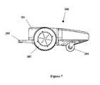
- FIG. 7is a right side view of the autonomous robot of FIG. 1 ;
- FIG. 8is a top perspective view of a docking station according to one embodiment of the present invention with the autonomous robot of FIG. 1 positioned therein;
- FIG. 9is a top view of the docking station of FIG. 8 ;
- FIG. 10is a flowchart of the steps that may be used to operate the autonomous robot of FIG. 1 according to one embodiment of the present invention
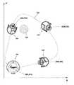
- FIG. 11is a schematic of the autonomous robot performing a perimeter mapping function to defines the desired area of confinement within which the autonomous robot will perform its task;
- FIG. 12is a schematic of the autonomous robot performing a coordinate mapping function to define the desired area of confinement within which the autonomous robot will perform its task;
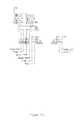
- FIG. 13is a high-level schematic of the control system of the autonomous robot of FIG. 1 according to an embodiment of the present invention
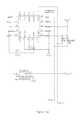
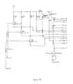
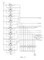
- FIG. 14is an electrical schematic of the control system of the autonomous robot of FIG. 1 according to an embodiment of the present invention.
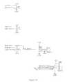
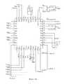
- FIG. 15is an electrical schematic of a hand-held remote control according to an embodiment of the present invention.
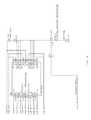
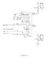
- FIG. 16is an electrical schematic of a charging unit according to an embodiment of the present invention.
- an autonomous robot 200 designed for mowing a lawnis illustrated according to one embodiment of the present invention. While the invention will be described in terms of an autonomous robot designed for mowing a lawn, it is to be understood that the control system and methods described herein can be implemented into any type of autonomous machine that must perform a desired activity within a desired area of confinement, including without limitation cleaning machines, polishing machines, repair machines, and/or demolition machines.
- the autonomous robot 200generally comprises a main housing 201 , a pair of drive wheels 202 , grass cutting blades 203 and steering wheels 204 .
- a handle 205is provided on the rear end of the housing 201 for convenience of handling and/or user-initiated movement.
- Three cutting blades 203are provided. However, more or less blades 203 can be implemented.
- the housing 201contains all of the internal circuitry and mechanical systems necessary to operate the autonomous robot 200 .
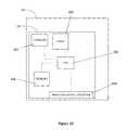
- the housing 201contains a robot control system 230 that contains all of the required internal circuitry.
- the robot control system 230includes a compass 231 , a timer 232 , an internal memory 233 and a wireless signal receiver 234 , all of which are operably connected to a CPU 235 .
- the wireless signal receiver 234is a sensor or other data receiving port for receiving signals from an external control unit.
- the sensorcan be an IR, RF, Wi-Fi or other sensor for receiving wired or wireless data signals.
- the external control unitis preferably a remote control, a PC, a PDA or a Smart Phone.
- autonomous robot 200is not to be considered limiting of the present invention, which is directed to the integrated control, mapping and operating systems and methods.
- the docking station 300provides a housing 301 for receiving the autonomous robot 200 .
- An opening 302is provided in the housing 301 through which the autonomous robot 200 can pass into the housing 301 for shelter and/or storage during periods of non-use.
- the autonomous robot 200can be positioned entirely within the housing 301 in a manner so that the handle 205 of the autonomous robot 200 can easily be grasped by a user so that a user can remove the autonomous robot 200 from the docking station 300 as needed.
- the autonomous robot 200may be removed by way of the remote control or may remove itself automatically upon being turned on and activated for a mowing session.
- the docking station 300can incorporate a battery charging station for charging the internal batteries of the autonomous robot 200 .
- the docking station 300may connect to a PC, PDA, or Smart Phone via Wi-Fi communication in order to present a user with information including, without limitation, a map of a bounded area.
- the docking station 300may connect to the above mentioned autonomous robot 200 via RF.
- the docking station 300is a communication gateway between a remote control, PC, PDA, or Smart Phone and the autonomous robot 200 .
- the docking station 300may also broadcast a signal that aids the autonomous robot 200 in navigation.
- the various modes of the autonomous robot 200dictate the processes and calculations involved in preparing the autonomous robot 200 for use as well as for actually using the autonomous robot 200 .
- the various modes of the autonomous robot 200include a Setup/Perimeter Mapping Mode, an Exclusion Area Mode, a Pattern Selection Mode and an Operational Mode.
- the inventionis not limited to having the four modes mentioned above and it may contain more or less than the four named modes as appropriate for its intended purpose. Each of the named modes will be discussed below with reference to FIGS. 10-12 below.
- the autonomous robot 200has an integrated control system 230 ( FIG. 13 ) that maps and stores a perimeter of the desired area of confinement 220 by relating its current position to an established starting point of the autonomous robot 200 as will be discussed below.
- the autonomous robot 200is able to stay within the defined perimeter of the desired area of confinement 220 by monitoring and mapping its own location with respect to the stored perimeter at all times.
- the docking station 300 discussed abovemay act as the starting/zero point for mapping the perimeter and/or resetting the present location of the autonomous robot 200 .
- the first sequence in preparing the autonomous robot 200 for use in a new environmentis for the user to go through the Setup Mode 110 , which as discussed in detail below, results in the definition of the bounded area (step 120 ).
- the Setup Mode 120is initiated by switching the autonomous robot 200 to the setup mode by manipulating a mechanical switch or an internal electrical signal switch that activates the CPU 235 within the robot control system 230 of the autonomous robot 200 to retrieve the setup commands and program sequencing which are stored in an internal memory device 233 .
- the Setup Modeis used to define the area of confinement 220 (also referred to herein as the operational perimeter) within which the autonomous robot 200 will perform its task (e.g., lawn mowing, floor cleaning, etc.).
- the autonomous robot 200Prior to activating the Setup Mode, the autonomous robot 200 is positioned at a point P 0 along the desired perimeter 220 and oriented facing the desired direction of travel. In a preferable embodiment (see FIG. 12 ), this point coincides with the location of the docking station 300 .
- a record starting point (“RSP”) signalis sent to the robot control system 230 via the hand-held remote control or a Wi-Fi interface device (or by the activation of a button on the autonomous robot 200 ) indicating that the autonomous robot 200 is in the desired starting position/location.
- This RSP signalis generated by activating the proper control on the interface of the remote control or Wi-Fi interface device or can be automatically generated upon switching into Setup Mode.
- the robot control system 230records this location as the starting point P 0 in its internal memory 233 (which acts as the internal point of reference).
- the starting point P 0may be recorded by the robot control system 230 as a coordinate in an XY or X ⁇ coordinate system.
- starting point P 0may be recorded by the robot control system 230 as the Cartesian coordinate (0, 0) which will then become the relative reference point upon which all subsequent locations are based.
- the robot control system 230will continuously record its location as a coordinate in an XY plane.
- FIG. 12illustrates the robot control system 230 recording four coordinates around the perimeter, the robot control system 230 is actually constantly recording the coordinates to the internal memory 233 so that the perimeter 220 can be mapped on an XY plane.
- the starting point P 0is preferably a position located on the perimeter 220 for simplicity and ease of computing, it is possible for the starting point P 0 to be offset from the perimeter 220 .
- the CPU 235 of the robot control system 230can be programmed to detect that the starting point P 0 was not a point on the perimeter 220 upon detecting that a closed-geometry has been formed (discussed below) that does not include the starting point P 0 .
- the autonomous robot 200is preferably positioned at the starting point P 0 prior to activating the Setup Mode, the autonomous robot 200 can be in a different position and moved to the desired starting point P 0 subsequent to the initiation of the Setup Mode.
- the RSP signalwill be generated by the user as desired, but preferably when the autonomous robot 200 is along the perimeter 220 .
- the closed-geometrymay be any shape that forms an enclosed boundary, such as a polygon.
- the closed-geometrycan be shapes other than polygons, such as circles, ovals or other enclosed shapes with curved sides, linear sides, rounded sides, and/or combinations thereof.
- the position of the docking station 300coincide with the location of the starting point P 0 ( FIG. 12 ).
- the useractivates movement of the autonomous robot 200 in a desired direction about the perimeter 220 .
- the userdirects the autonomous robot 200 around the perimeter 220 with a remote control or Wi-Fi interface which enables the user to move and steer the autonomous robot 200 in a desired direction.
- the autonomous robot 200tracks and records its own location (and direction of movement) internally via the robot control system 230 .
- the autonomous robot 200preferably tracks and records its location with the use of the compass 231 and the timer 232 .
- the compass 231which is located within the autonomous robot 200 and is operably coupled to a CPU 235 , provides a direction/bearing for the movement of the autonomous robot 200 at all times.
- the autonomous robot 200need not have the compass 231 and other directional indicating instruments as would be known to persons skilled in the art may be used in lieu of the compass 231 .
- the timing of the movement of the autonomous robot 200 along the established bearing/directionis measured by the timer 232 , which is also operably coupled to the CPU 235 .
- the autonomous robot 200does not need to have the timer 232 and other sensors or mechanisms for monitoring electrical signal characteristics may be used instead of the timer 232 .
- the timer 232acts as a distance-traveled measuring mechanism.
- the CPU 235will be able to calculate the distance and direction which the autonomous robot 200 has traveled during this first period of movement based on the signals from the timer 232 and the compass 231 . In other words, the CPU 235 will calculate and map the current location of the autonomous robot 200 with respect to the starting point P 0 and record the appropriate data in the memory 233 .
- the first period of movementresults in the CPU 235 mapping a first vector V 1 having a distance value and an angle.
- the mapping/recording of any single vector or positional update by the CPU 235can be continuous, periodical or initiated by a substantial change in direction/bearing of the autonomous robot 200 .
- V 1is mapped, the user continues moving and steering the autonomous robot 200 about the desired perimeter 220 , thereby resulting in the CPU mapping and recording the remaining vectors V 2 -V 5 based on the information provided by the timer and the compass.
- a Cartesian coordinate mapping schemeas discussed above with reference to FIG. 12 , can be used by the CPU 235 to the same effect.
- the autonomous robot 200can, at all times, be aware of its location with respect to the starting point P 0 .
- the directional indicating instrumentis preferably a compass, other devices can be used.
- the distance-traveled measuring mechanismis exemplified as a timer 232 and constant velocity drive, a variety of sensors, mechanisms for monitoring electrical signal characteristics and/or timers can be used to determine the distance traveled by the autonomous robot 200 .
- a sensorcan be operably connected to the axle or wheel to record revolutions, which through simple mathematical relationships, can be correlated to the distance traveled so long as the radii of the drive wheels 202 are known.
- averaging and differentiation techniquescan also be used.
- any of the aforementioned computations of distancecan take into account changes and/or variations in velocity, acceleration, bearing and/or combinations thereof experienced by the autonomous robot 200 in real world conditions.
- Other variablessuch as wheel slippage, obstruction, and/or delay, can also be taken into consideration in computing the distance.
- wheel slippage, obstruction, and/or delaycan be measured by monitoring the current usage of the drive motors. All of the information relating to the variables can be stored in the internal memory 233 and retrieved by the CPU 235 on an as-needed basis.
- the compass and distance measurementscan be replaced or supplemented with other apparatus used in precise navigation that can be adapted to the use of the autonomous robot 200 .
- a first exampleincludes the detection of signals from a plurality of satellites in orbit around the planet Earth, such as Global Positioning System (GPS), Global Navigation Satellite System (GLONASS), Galileo or similar satellite signals that broadcast time or navigational measurements using a receiver.
- GPSGlobal Positioning System
- GLONASSGlobal Navigation Satellite System
- GalileoGalileo or similar satellite signals that broadcast time or navigational measurements using a receiver.
- the compass and distance measurementscan be replaced or supplemented with other apparatus used in triangulation that can be adapted to the use of the autonomous robot 200 .
- a first exampleincludes the detection of signals from a plurality of radio beacons that broadcast navigational data placed around the perimeter of the area of interest.
- the compass and distance measurementsmay be processed on a host computer connected to the autonomous robot 200 over a wireless connection to the Internet.
- a first exampleincludes differential correction of navigational measurements where one source of navigational measurements transmits corrected information to the second source of navigational measurements using radio signals, such as in the art and practice of differential GPS (DGPS).
- DGPSdifferential GPS
- the CPU 235either automatically recognizes that a closed-geometry has been formed (through proper programming) or the user activates a compute closed perimeter (“CCP”) signal that is received by the CPU 235 by activating the proper button on the interface of the remote control, PC, PDA, or Smart Phone.
- CCPcompute closed perimeter
- the remote controlmay have a display which displays the map created by the CPU 235 .
- the autonomous robot 200may connect to a PC, PDA, or Smart Phone via Wi-Fi which displays the map created by the CPU 235 . This allows the user to get a general idea of whether the perimeter mapping sequence was a success.
- the CPU 235will record the mapped perimeter 220 and use it as the limitations of its area of confinement during a work session.
- autonomous robot 200serves as a lawn mower and the defined bounded area 220 surrounds a yard.
- the usermay program the autonomous robot 200 with multiple perimeters in which the autonomous robot 200 will travel to each perimeter and use it as the limitations of its area of confinement during a work session. This allows the autonomous robot 200 to travel between different parts of a lawn, for example, front and back yards.
- step 120is complete.
- the robot control system 230then translates the area within the perimeter 220 to a grid and grids the bounded area, thereby completing step 130 .
- the next stepis for the user to select a pattern that will define the behavior of the autonomous robot 200 while traveling inside the defined perimeter 220 while performing its task.
- Possible patternsinclude random, semi-random, or specific patterns whereby the autonomous robot 200 may travel in stripes, circles, squares, or any other pre-specified pattern.
- the CPU 235may calculate a number of possible patterns based on the application of preprogrammed algorithms to that particular defined perimeter 220 .
- the patternmay be transmitted to the autonomous robot 200 via a PC, PDA, or Smart Phone.
- the autonomous robot 200is put into operational mode where it begins the step of maneuvering across an area defined by bounded area 220 , thereby completing step 150 .
- Robot control system 230may use the boundary information, robot dimensions (cutting width), and exclusion information to generate a grid or map that indicates where the autonomous robot 200 should travel, should not travel or has already traveled. This includes the step of tracking completed grid points (step 160 ). With all of this information stored in the internal memory 233 of the robot control system 230 , the robot control system 230 navigates the autonomous robot 200 inside the boundary 220 according to the selected pattern.
- the robot control system 230can also store exclusion information for use in directing the autonomous robot 200 .
- the userIn order to input exclusion information into the robot control system 230 , the user must set the device to the Exclusion Area Mode by activating a manual, internal or electronic switch. In this mode, the user can define exclusion zones, or portions within the defined bounded area 220 that the user does not want the autonomous robot 200 to travel.
- the userIn order to create these exclusion points, the user must initially position the autonomous robot 200 at a starting point and initialize the Exclusion Area Mode. Initialization may take place either by sending a signal to the robot control system 230 (via the remote control or other Wi-Fi device) or it may automatically occur by positioning the autonomous robot 200 at a location within the area of confinement and then setting the autonomous robot 200 to the Exclusion Area Mode. Next, through use of the remote control or other Wi-Fi device, the user must move/drive the autonomous robot 200 around the area of exclusion (i.e. around a tree, around a deck, or around a garden, illustrated generically as a circle 260 in FIG. 12 ).
- the area of exclusioni.e. around a tree, around a deck, or around a garden, illustrated generically as a circle 260 in FIG. 12 ).
- the usercan define additional exclusion zones by repeating this step at different locations within the defined bounded area until satisfied.
- the robot control system 230performs a mapping function similar to that discussed above with respect to the Setup Mode but instead uses the defined closed-geometry to define an area of exclusion in which the autonomous robot 200 will not be allowed to travel.
- the robot control system 230then knows to direct the autonomous robot 200 to steer clear of the exclusionary zones and to focus on performing its task elsewhere (within the perimeter 220 ).
- the robot control system 230uses the boundary information, the robot dimensions, such as, for example, the cutting width, exclusion area information and selected course pattern information to generate a grid or map and path that indicates where the autonomous robot 200 should travel. Using all of this information, the autonomous robot 200 is able to perform a desired task within a bounded area as desired.
- the robot control system 230is able to detect when the autonomous robot 200 has completed its task or has a low battery.
- the robot control system 230is constantly aware of the location of the autonomous robot 200 within the defined bounded area 220 by coordinates or other mapping techniques as discussed above. As such, the robot control system 230 is able to prevent the autonomous robot 200 from leaving the defined bounded area and guide the autonomous robot 200 to other bounded areas and back to the point P 0 .
- the robot control system 230may direct the autonomous robot 200 to return to the docking station 300 for docking or recharging and then direct the autonomous robot 200 back to the point P 0 .
- the robot control system 230uses a Secure Pin to activate the autonomous robot 200 .
- This Secure Pinmay serve as a theft deterrent to prevent the unauthorized use or possession of the autonomous robot 200 .
- the robot control system 230may connect to a PC, PDA, or Smart Phone via Wi-Fi. When so connected, robot control system 230 sends registration information such as location (based on IP address), diagnostic information (i.e. state of health), and other information to a server. This information may prove helpful in identifying a stolen autonomous robot 200 and in determining how parts are failing.
- the robot control system 230is also able to detect which portions within the defined bounded area 220 have already been traversed by the autonomous robot 200 during a cutting session. Thus, if the autonomous robot 200 needs to be recharged in the middle of a lawn cutting session, the autonomous robot 200 can continue its job from where it left off once its batteries are recharged.
- the robot control system 230knows the exact location of the autonomous robot 200 at all times. Thus, the robot control system 230 is able to keep track of the completed grid points and steer the autonomous robot 200 away from those grid points that it has already performed its task on so that it can complete its task on other grid points within the bounded area 220 . Furthermore, the robot control system 230 may also comprise an internal date and time circuit so that the autonomous robot 200 performs its task only at desired times and days.
- control system 230would also be programmed with a “reset” feature that could be activated automatically by the autonomous robot 200 or user. In such a situation, the user would return the autonomous robot 200 to the point P 0 and activate the reset feature. This “reset” would automatically reset the perceived location of the autonomous robot 200 to point P 0 without erasing the defined perimeter or exclusion areas.
- the autonomous robot 200may be equipped with an emergency shut-off in order to avoid the potential for harm to a person or object.
- the emergency shut-offwill automatically shut down the autonomous robot 200 if it happens to travel outside of the defined bounded area 220 .
- the usermay also desire to shut down the autonomous robot 200 while it is performing its task. This can be done by pressing an off button on the remote control or other Wi-Fi interface.
- the autonomous robot 200may also include various behaviors for escape to allow the autonomous robot 200 to avoid becoming stuck.
- the autonomous robot 200may include foldable legs with wheels on the ends to lift the autonomous robot 200 off of the ground and move it to a location that is better suited for performing its task. This may prove helpful if, for example, the autonomous robot 200 becomes stuck on a tree root and is unable to maneuver itself beyond the tree root while affixed to the ground. Additional escape behaviors as would be known to those skilled in the art have also been contemplated within the scope of the present invention.
- FIG. 14an electrical schematic of a robot control system is illustrated.
- the electrical schematic of FIG. 14shows all of the electrical components that are necessary to operate the autonomous robot 200 including the distance-traveled measuring mechanism, the directional indicating instrument, the memory device, the data receiving port and the central processing unit.
- FIG. 15an electrical schematic of a hand-held remote control that may be used to operate the autonomous robot 200 is illustrated.
- the hand-held remote controlis capable of communicating with the data receiving port of the control system in order to maneuver the autonomous robot 200 around the perimeters as discussed above as well as to send the necessary signals to the autonomous robot 200 as discussed above.
- FIG. 16an electrical schematic of a charging unit that may be used to charge the batteries of the autonomous robot 200 is illustrated.
- the charging unitmay be incorporated into the docking station 300 .
- the circuitry illustrated in FIG. 16may be incorporated into the housing 301 of the docket station 300 .
- the circuitry illustrated in FIG. 16may be contained within a separate component such as, for example, a plug-and-play type of device.
Landscapes
- Engineering & Computer Science (AREA)
- Radar, Positioning & Navigation (AREA)
- Life Sciences & Earth Sciences (AREA)
- Environmental Sciences (AREA)
- Aviation & Aerospace Engineering (AREA)
- Remote Sensing (AREA)
- Physics & Mathematics (AREA)
- General Physics & Mathematics (AREA)
- Automation & Control Theory (AREA)
- Control Of Position, Course, Altitude, Or Attitude Of Moving Bodies (AREA)
Abstract
Description
Claims (20)
Priority Applications (5)
| Application Number | Priority Date | Filing Date | Title |
|---|---|---|---|
| US12/818,590US8428776B2 (en) | 2009-06-18 | 2010-06-18 | Method for establishing a desired area of confinement for an autonomous robot and autonomous robot implementing a control system for executing the same |
| US13/452,244US8706297B2 (en) | 2009-06-18 | 2012-04-20 | Method for establishing a desired area of confinement for an autonomous robot and autonomous robot implementing a control system for executing the same |
| US14/258,678US20140222197A1 (en) | 2009-06-18 | 2014-04-22 | System and method for monitoring operation of an autonomous robot |
| US14/934,232US10485164B2 (en) | 2009-06-18 | 2015-11-06 | System and method for controlling and monitoring operation of an autonomous robot |
| US16/660,204US11439058B2 (en) | 2009-06-18 | 2019-10-22 | System and method for controlling and monitoring operation of an autonomous robot |
Applications Claiming Priority (2)
| Application Number | Priority Date | Filing Date | Title |
|---|---|---|---|
| US21827909P | 2009-06-18 | 2009-06-18 | |
| US12/818,590US8428776B2 (en) | 2009-06-18 | 2010-06-18 | Method for establishing a desired area of confinement for an autonomous robot and autonomous robot implementing a control system for executing the same |
Related Child Applications (1)
| Application Number | Title | Priority Date | Filing Date |
|---|---|---|---|
| US13/452,244Continuation-In-PartUS8706297B2 (en) | 2009-06-18 | 2012-04-20 | Method for establishing a desired area of confinement for an autonomous robot and autonomous robot implementing a control system for executing the same |
Publications (2)
| Publication Number | Publication Date |
|---|---|
| US20100324731A1 US20100324731A1 (en) | 2010-12-23 |
| US8428776B2true US8428776B2 (en) | 2013-04-23 |
Family
ID=43354998
Family Applications (1)
| Application Number | Title | Priority Date | Filing Date |
|---|---|---|---|
| US12/818,590Active - Reinstated2030-12-14US8428776B2 (en) | 2009-06-18 | 2010-06-18 | Method for establishing a desired area of confinement for an autonomous robot and autonomous robot implementing a control system for executing the same |
Country Status (1)
| Country | Link |
|---|---|
| US (1) | US8428776B2 (en) |
Cited By (46)
| Publication number | Priority date | Publication date | Assignee | Title |
|---|---|---|---|---|
| US20120255938A1 (en)* | 2011-04-08 | 2012-10-11 | Kabushiki Kaisha Yaskawa Denki | Robot system |
| US20130006419A1 (en)* | 2010-03-17 | 2013-01-03 | Husqvarna Ab | Method and system for navigating a robotic garden tool |
| US20130061417A1 (en)* | 2011-09-09 | 2013-03-14 | Dyson Technology Limited | Autonomous cleaning appliance |
| US20150293533A1 (en)* | 2014-04-13 | 2015-10-15 | Bobsweep Inc. | Scanned Code Instruction and Confinement Sytem for Mobile Electronic Devices |
| US20150366130A1 (en)* | 2013-02-20 | 2015-12-24 | Husqvarna Ab | A Robotic Work Tool Configured for Improved Turning in a Slope, a Robotic Work Tool System, and a Method for Use in the Robot Work Tool |
| USD758455S1 (en) | 2015-06-05 | 2016-06-07 | Mtd Products Inc | Robotic mower body |
| USD760806S1 (en) | 2015-06-05 | 2016-07-05 | Mtd Products Inc | Robotic mower |
| CN105796002A (en)* | 2016-03-31 | 2016-07-27 | 北京小米移动软件有限公司 | Indoor cleaning method for cleaning robot, cleaning robot and mobile terminal |
| US9462920B1 (en) | 2015-06-25 | 2016-10-11 | Irobot Corporation | Evacuation station |
| USD781349S1 (en) | 2016-02-16 | 2017-03-14 | Mtd Products Inc | Robotic mower housing |
| USD792198S1 (en) | 2015-10-29 | 2017-07-18 | Mtd Products Inc | Caster wheel |
| USD794089S1 (en) | 2015-06-05 | 2017-08-08 | Mtd Products Inc | Wheel |
| USD795299S1 (en) | 2016-02-16 | 2017-08-22 | Mtd Products Inc | Blade |
| USD795300S1 (en) | 2016-08-23 | 2017-08-22 | Mtd Products Inc | Blade |
| USD797530S1 (en) | 2015-06-05 | 2017-09-19 | Mtd Products Inc | Blade |
| US9764473B1 (en) | 2014-10-01 | 2017-09-19 | Bobsweep Inc. | System and method for confinement of a robotic device |
| US20180009059A1 (en)* | 2016-07-08 | 2018-01-11 | Fanuc Corporation | Laser Processing Robot System for Performing Laser Processing Using Robot |
| US9930829B2 (en) | 2015-05-27 | 2018-04-03 | Mtd Products Inc | Self-cleaning mower blade assembly |
| US10212880B2 (en) | 2016-06-24 | 2019-02-26 | Mtd Products Inc | High-efficiency cutting system |
| USD848488S1 (en) | 2016-08-23 | 2019-05-14 | Mtd Products Inc | Robotic mower housing |
| US10433480B2 (en) | 2016-04-20 | 2019-10-08 | Mtd Products Inc | Low-energy blade system having a quick-attach mechanism |
| US10545504B2 (en) | 2015-04-01 | 2020-01-28 | AI Incorporated | System and method for establishing virtual boundaries for robotic devices |
| US10579066B1 (en) | 2015-03-30 | 2020-03-03 | AI Incorporated | System and method for establishing virtual boundaries for robotic devices |
| USD889517S1 (en) | 2019-01-31 | 2020-07-07 | Mtd Products Inc | Robotic mower body |
| USD892187S1 (en) | 2018-11-30 | 2020-08-04 | Mtd Products Inc | Robotic mower |
| US10806076B2 (en) | 2017-10-06 | 2020-10-20 | Mtd Products Inc | High-efficiency lawn maintenance tool and high-efficiency cutting blade |
| US10824143B2 (en) | 2016-04-08 | 2020-11-03 | A&K Robotics Inc. | Autoscrubber convertible between manual and autonomous operation |
| US10845817B1 (en)* | 2016-08-11 | 2020-11-24 | Ali Ebrahimi Afrouzi | System and method for confining robotic devices |
| WO2021014117A1 (en) | 2019-07-22 | 2021-01-28 | Kingdom Technologies Ltd | Robotic lawn mower control |
| US10932409B2 (en) | 2017-11-20 | 2021-03-02 | The Toro Company | System and method for operating an autonomous robotic working machine within a travelling containment zone |
| US20210161065A1 (en)* | 2018-06-26 | 2021-06-03 | Husqvarna Ab | Method for Updating a Collision Detection Algorithm in a Self-Propelled Robotic Tool |
| US11045958B2 (en) | 2012-08-03 | 2021-06-29 | Stryker Corporation | Surgical robotic system and method for commanding instrument position based on iterative boundary evaluation |
| US11179210B2 (en) | 2012-08-03 | 2021-11-23 | Stryker Corporation | Surgical manipulator and method for controlling pose of an instrument based on virtual rigid body modelling |
| US11192204B2 (en)* | 2017-02-09 | 2021-12-07 | Fanuc Corporation | Laser machining system including laser machining head and imaging device |
| US11347239B1 (en) | 2014-10-01 | 2022-05-31 | AI Incorporated | System and method for establishing virtual boundaries for robotic devices |
| US11471232B2 (en) | 2012-08-03 | 2022-10-18 | Stryker Corporation | Surgical system and method utilizing impulse modeling for controlling an instrument |
| USD971271S1 (en) | 2021-06-25 | 2022-11-29 | Mtd Products Inc | Robotic mower |
| USD971272S1 (en) | 2021-06-25 | 2022-11-29 | Mtd Products Inc | Robotic mower body |
| US11582903B1 (en)* | 2017-05-17 | 2023-02-21 | Hydro-Gear Limited Partnership | Vision based guidance system and method for lawn mowing devices |
| USD980873S1 (en) | 2021-07-23 | 2023-03-14 | Mtd Products Inc | Robotic mower |
| USD980874S1 (en) | 2021-07-23 | 2023-03-14 | Mtd Products Inc | Robotic mower body |
| US11917938B2 (en) | 2022-07-05 | 2024-03-05 | Willand (Beijing) Technology Co., Ltd. | Method for constructing map for mower, storage medium, mower, and mobile terminal |
| US12296694B2 (en) | 2021-03-10 | 2025-05-13 | Techtronic Cordless Gp | Lawnmowers |
| US12369509B2 (en) | 2022-07-19 | 2025-07-29 | Techtronic Cordless Gp | Display for controlling robotic tool |
| US12425197B2 (en) | 2022-07-29 | 2025-09-23 | Techtronic Cordless Gp | Generation of a cryptography key for a robotic garden tool |
| US12443180B2 (en) | 2022-11-09 | 2025-10-14 | Techtronic Cordless Gp | Robotic lawn mowers |
Families Citing this family (56)
| Publication number | Priority date | Publication date | Assignee | Title |
|---|---|---|---|---|
| EP3067771B1 (en) | 2006-03-17 | 2017-11-08 | iRobot Corporation | Robot confinement |
| WO2012140655A2 (en)* | 2011-04-12 | 2012-10-18 | Baryakar Dan | Robotic system controlled by multi participants, considering administrator's criteria |
| KR101850386B1 (en)* | 2011-04-19 | 2018-04-19 | 엘지전자 주식회사 | Robot cleaner and controlling method of the same |
| TW201305761A (en)* | 2011-07-21 | 2013-02-01 | Ememe Robot Co Ltd | An autonomous robot and a positioning method thereof |
| DE102011085488A1 (en)* | 2011-10-31 | 2013-05-02 | Robert Bosch Gmbh | Autonomous working device |
| US9320074B2 (en)* | 2012-04-06 | 2016-04-19 | Suitable Technologies, Inc. | Method for wireless connectivity continuity and quality |
| EP2656720B1 (en)* | 2012-04-24 | 2015-11-04 | Robert Bosch GmbH | Cutter guard for a lawn mower |
| EP2689650B1 (en) | 2012-07-27 | 2014-09-10 | Honda Research Institute Europe GmbH | Trainable autonomous lawn mower |
| EP2885683A4 (en)* | 2012-08-14 | 2016-06-01 | Husqvarna Ab | Boundary definition system for a robotic vehicle |
| AU2013204965B2 (en) | 2012-11-12 | 2016-07-28 | C2 Systems Limited | A system, method, computer program and data signal for the registration, monitoring and control of machines and devices |
| DE102013107492A1 (en) | 2013-07-15 | 2015-01-15 | Koubachi AG | System for monitoring and controlling activities of at least one gardening tool within at least one activity area |
| EP2870853A1 (en) | 2013-11-11 | 2015-05-13 | Honda Research Institute Europe GmbH | Lawn mower with remote control |
| EP2870852A1 (en) | 2013-11-11 | 2015-05-13 | Honda Research Institute Europe GmbH | Lawn mower with network communication |
| EP3126921B1 (en)* | 2014-03-31 | 2021-02-24 | iRobot Corporation | Autonomous mobile robot |
| US9851718B2 (en)* | 2014-09-26 | 2017-12-26 | Steven R. Booher | Intelligent control apparatus, system, and method of use |
| US9804594B2 (en)* | 2014-11-07 | 2017-10-31 | Clearpath Robotics, Inc. | Self-calibrating sensors and actuators for unmanned vehicles |
| EP3237984B1 (en) | 2014-12-22 | 2018-12-19 | Husqvarna AB | Area exclusion for operation of a robotic vehicle |
| US9538702B2 (en)* | 2014-12-22 | 2017-01-10 | Irobot Corporation | Robotic mowing of separated lawn areas |
| WO2016103067A1 (en)* | 2014-12-22 | 2016-06-30 | Husqvarna Ab | Garden mapping and planning via robotic vehicle |
| US20190381665A1 (en)* | 2015-05-08 | 2019-12-19 | C2 Systems Limited | System, method, computer program and data signal for the registration, monitoring and control of machines and devices |
| DE102015109775B3 (en) | 2015-06-18 | 2016-09-22 | RobArt GmbH | Optical triangulation sensor for distance measurement |
| DE102015114883A1 (en)* | 2015-09-04 | 2017-03-09 | RobArt GmbH | Identification and localization of a base station of an autonomous mobile robot |
| EP3156873B2 (en) | 2015-10-15 | 2023-04-05 | Honda Research Institute Europe GmbH | Autonomous vehicle with improved simultaneous localization and mapping function |
| DE102015119501A1 (en) | 2015-11-11 | 2017-05-11 | RobArt GmbH | Subdivision of maps for robot navigation |
| DE102015119865B4 (en) | 2015-11-17 | 2023-12-21 | RobArt GmbH | Robot-assisted processing of a surface using a robot |
| DE102015121666B3 (en) | 2015-12-11 | 2017-05-24 | RobArt GmbH | Remote control of a mobile, autonomous robot |
| KR20170077756A (en)* | 2015-12-28 | 2017-07-06 | 삼성전자주식회사 | Cleaning robot and controlling method thereof |
| DE102016102644A1 (en)* | 2016-02-15 | 2017-08-17 | RobArt GmbH | Method for controlling an autonomous mobile robot |
| JP7073336B2 (en) | 2016-08-05 | 2022-05-23 | ロブアート ゲーエムベーハー | How to control an autonomous mobile robot |
| WO2018093809A2 (en) | 2016-11-16 | 2018-05-24 | Wal-Mart Stores, Inc. | Systems and methods to deter theft of commercial products |
| USD842907S1 (en)* | 2016-12-15 | 2019-03-12 | Lg Electronics Inc. | Robot lawn mower |
| USD842343S1 (en)* | 2016-12-15 | 2019-03-05 | Lg Electronics Inc. | Robot lawn mower |
| USD842906S1 (en)* | 2016-12-15 | 2019-03-12 | Lg Electronics Inc. | Robot lawn mower |
| EP3974934A1 (en) | 2017-03-02 | 2022-03-30 | Robart GmbH | Method for controlling an autonomous mobile robot |
| DE102017109219A1 (en) | 2017-04-28 | 2018-10-31 | RobArt GmbH | Method for robot navigation |
| EP3669629A4 (en)* | 2017-08-18 | 2021-05-19 | Suzhou Cleva Precision Machinery & Technology Co., Ltd. | Smart mower |
| CN108852174B (en) | 2017-09-25 | 2022-02-25 | 北京石头创新科技有限公司 | Autonomous mobile robot and pile searching method, control device and intelligent cleaning system thereof |
| CN108873879B (en)* | 2017-09-25 | 2022-03-04 | 北京石头创新科技有限公司 | Autonomous mobile robot and its pile finding method, control device and intelligent cleaning system |
| US20190187721A1 (en)* | 2017-12-15 | 2019-06-20 | Ankobot (Shanghai) Smart Technologies Co., Ltd. | Control method and system, and mobile robot using the same |
| USD876487S1 (en)* | 2018-01-11 | 2020-02-25 | Lg Electronics Inc. | Robot lawn mower |
| US10885768B2 (en)* | 2018-02-12 | 2021-01-05 | Tennant Company | Systems and methods for measuring performance of site maintenance |
| SE544390C2 (en)* | 2019-03-05 | 2022-05-03 | Husqvarna Ab | Robotic work tool system and method for controlling a robotic work tool based on information from a recording device |
| KR102224637B1 (en) | 2019-07-05 | 2021-03-08 | 엘지전자 주식회사 | Moving robot and control method thereof |
| KR102275300B1 (en) | 2019-07-05 | 2021-07-08 | 엘지전자 주식회사 | Moving robot and control method thereof |
| KR102361130B1 (en)* | 2019-07-11 | 2022-02-09 | 엘지전자 주식회사 | Moving robot and control method thereof |
| KR102297496B1 (en) | 2019-07-11 | 2021-09-02 | 엘지전자 주식회사 | A ROBOT CLEANER Using artificial intelligence AND CONTROL METHOD THEREOF |
| KR102302575B1 (en) | 2019-07-16 | 2021-09-14 | 엘지전자 주식회사 | Moving robot and control method thereof |
| KR20190108530A (en)* | 2019-09-04 | 2019-09-24 | 엘지전자 주식회사 | Mobile robot and method for operating the same |
| KR20210061610A (en)* | 2019-11-20 | 2021-05-28 | 엘지전자 주식회사 | Moving robot and controlling method for the same |
| KR20210115714A (en)* | 2020-03-16 | 2021-09-27 | 삼성전자주식회사 | Lawn mower robot |
| CN111745687B (en)* | 2020-07-03 | 2023-03-14 | 中煤科工集团重庆研究院有限公司 | Charging and butting mechanism and method for mining inspection robot based on drum-shaped gear |
| JP7574568B2 (en)* | 2020-08-17 | 2024-10-29 | 村田機械株式会社 | Autonomous driving route planning method |
| EP3968051B1 (en)* | 2020-09-15 | 2024-10-30 | Infineon Technologies AG | Guiding system for a robot, base station including such a guiding system, and method for guiding a robot |
| US12239045B2 (en) | 2022-02-24 | 2025-03-04 | Mowzr, Inc. | Autonomous mower system |
| CN118697241A (en)* | 2023-03-20 | 2024-09-27 | 科沃斯机器人股份有限公司 | Map processing method, system, autonomous driving device and client device |
| DE102023135330A1 (en)* | 2023-12-15 | 2025-06-18 | Alfred Kärcher SE & Co. KG | Self-propelled and self-steering floor cleaning machine with carrying handle |
Citations (19)
| Publication number | Priority date | Publication date | Assignee | Title |
|---|---|---|---|---|
| US5204814A (en) | 1990-11-13 | 1993-04-20 | Mobot, Inc. | Autonomous lawn mower |
| EP0774702A2 (en) | 1995-11-07 | 1997-05-21 | Friendly Machines Ltd. | A boundary detection system for an automated robot |
| US5974347A (en) | 1997-03-14 | 1999-10-26 | Nelson; Russell G. | Automated lawn mower |
| US6255793B1 (en)* | 1995-05-30 | 2001-07-03 | Friendly Robotics Ltd. | Navigation method and system for autonomous machines with markers defining the working area |
| US6339735B1 (en) | 1998-12-29 | 2002-01-15 | Friendly Robotics Ltd. | Method for operating a robot |
| US20030030398A1 (en)* | 2001-08-13 | 2003-02-13 | Stephen Jacobs | Mapped robot system |
| US20040010343A1 (en) | 2002-03-28 | 2004-01-15 | Dean Jason A. | Programmable lawn mower |
| US7103457B2 (en) | 2002-03-28 | 2006-09-05 | Dean Technologies, Inc. | Programmable lawn mower |
| US7117660B1 (en) | 2000-04-12 | 2006-10-10 | Colens Andre | Self-propelled lawn mower |
| EP1721279A2 (en) | 2004-02-03 | 2006-11-15 | F. Robotics Aquisitions Ltd. | Robot docking station and robot for use therewith |
| US7239944B2 (en) | 2002-03-28 | 2007-07-03 | Dean Jason A | Programmable lawn mower |
| US20080109126A1 (en) | 2006-03-17 | 2008-05-08 | Irobot Corporation | Lawn Care Robot |
| US20090044370A1 (en)* | 2006-05-19 | 2009-02-19 | Irobot Corporation | Removing debris from cleaning robots |
| US20100106356A1 (en)* | 2008-10-24 | 2010-04-29 | The Gray Insurance Company | Control and systems for autonomously driven vehicles |
| EP2260690A2 (en) | 2008-02-15 | 2010-12-15 | Gunter Arnold | Navigation system for an autonomously mobile robot, in particular lawn mower robot |
| EP2330473A2 (en) | 2001-06-12 | 2011-06-08 | iRobot Corporation | Mobile robot |
| US8019475B2 (en)* | 2007-04-06 | 2011-09-13 | Honda Motor Co., Ltd. | Routing apparatus for autonomous mobile unit |
| US8234848B2 (en) | 2010-07-28 | 2012-08-07 | Deere & Company | Robotic mower height of cut adjustment assembly |
| US20120212638A1 (en) | 2009-07-01 | 2012-08-23 | Case Western Reserve University | Visual segmentation of lawn grass |
- 2010
- 2010-06-18USUS12/818,590patent/US8428776B2/enactiveActive - Reinstated
Patent Citations (22)
| Publication number | Priority date | Publication date | Assignee | Title |
|---|---|---|---|---|
| US5204814A (en) | 1990-11-13 | 1993-04-20 | Mobot, Inc. | Autonomous lawn mower |
| US6255793B1 (en)* | 1995-05-30 | 2001-07-03 | Friendly Robotics Ltd. | Navigation method and system for autonomous machines with markers defining the working area |
| US6417641B2 (en) | 1995-05-30 | 2002-07-09 | Friendly Robotics Ltd. | Navigation method and system for autonomous machines with markers defining the working area |
| EP0774702A2 (en) | 1995-11-07 | 1997-05-21 | Friendly Machines Ltd. | A boundary detection system for an automated robot |
| US5974347A (en) | 1997-03-14 | 1999-10-26 | Nelson; Russell G. | Automated lawn mower |
| US6339735B1 (en) | 1998-12-29 | 2002-01-15 | Friendly Robotics Ltd. | Method for operating a robot |
| US6493613B2 (en) | 1998-12-29 | 2002-12-10 | Friendly Robotics Ltd. | Method for operating a robot |
| US7117660B1 (en) | 2000-04-12 | 2006-10-10 | Colens Andre | Self-propelled lawn mower |
| EP2330473A2 (en) | 2001-06-12 | 2011-06-08 | iRobot Corporation | Mobile robot |
| US20030030398A1 (en)* | 2001-08-13 | 2003-02-13 | Stephen Jacobs | Mapped robot system |
| US7107132B2 (en) | 2002-03-28 | 2006-09-12 | Dean Technologies, Inc. | Programmable lawn mower |
| US7103457B2 (en) | 2002-03-28 | 2006-09-05 | Dean Technologies, Inc. | Programmable lawn mower |
| US7239944B2 (en) | 2002-03-28 | 2007-07-03 | Dean Jason A | Programmable lawn mower |
| US20040010343A1 (en) | 2002-03-28 | 2004-01-15 | Dean Jason A. | Programmable lawn mower |
| EP1721279A2 (en) | 2004-02-03 | 2006-11-15 | F. Robotics Aquisitions Ltd. | Robot docking station and robot for use therewith |
| US20080109126A1 (en) | 2006-03-17 | 2008-05-08 | Irobot Corporation | Lawn Care Robot |
| US20090044370A1 (en)* | 2006-05-19 | 2009-02-19 | Irobot Corporation | Removing debris from cleaning robots |
| US8019475B2 (en)* | 2007-04-06 | 2011-09-13 | Honda Motor Co., Ltd. | Routing apparatus for autonomous mobile unit |
| EP2260690A2 (en) | 2008-02-15 | 2010-12-15 | Gunter Arnold | Navigation system for an autonomously mobile robot, in particular lawn mower robot |
| US20100106356A1 (en)* | 2008-10-24 | 2010-04-29 | The Gray Insurance Company | Control and systems for autonomously driven vehicles |
| US20120212638A1 (en) | 2009-07-01 | 2012-08-23 | Case Western Reserve University | Visual segmentation of lawn grass |
| US8234848B2 (en) | 2010-07-28 | 2012-08-07 | Deere & Company | Robotic mower height of cut adjustment assembly |
Cited By (74)
| Publication number | Priority date | Publication date | Assignee | Title |
|---|---|---|---|---|
| US20130006419A1 (en)* | 2010-03-17 | 2013-01-03 | Husqvarna Ab | Method and system for navigating a robotic garden tool |
| US8938318B2 (en)* | 2010-03-17 | 2015-01-20 | Husqvarna Ab | Method and system for navigating a robotic garden tool |
| US20120255938A1 (en)* | 2011-04-08 | 2012-10-11 | Kabushiki Kaisha Yaskawa Denki | Robot system |
| US8742290B2 (en)* | 2011-04-08 | 2014-06-03 | Kabushiki Kaisha Yaskawa Denki | Robot system |
| US20130061417A1 (en)* | 2011-09-09 | 2013-03-14 | Dyson Technology Limited | Autonomous cleaning appliance |
| US9999328B2 (en)* | 2011-09-09 | 2018-06-19 | Dyson Technology Limited | Autonomous cleaning appliance |
| US11639001B2 (en) | 2012-08-03 | 2023-05-02 | Stryker Corporation | Robotic system and method for reorienting a surgical instrument |
| US12004836B2 (en) | 2012-08-03 | 2024-06-11 | Stryker Corporation | Surgical manipulator and method of operating the same using virtual rigid body modeling preliminary |
| US12070288B2 (en) | 2012-08-03 | 2024-08-27 | Stryker Corporation | Robotic system and method for removing a volume of material from a patient |
| US11471232B2 (en) | 2012-08-03 | 2022-10-18 | Stryker Corporation | Surgical system and method utilizing impulse modeling for controlling an instrument |
| US11045958B2 (en) | 2012-08-03 | 2021-06-29 | Stryker Corporation | Surgical robotic system and method for commanding instrument position based on iterative boundary evaluation |
| US11179210B2 (en) | 2012-08-03 | 2021-11-23 | Stryker Corporation | Surgical manipulator and method for controlling pose of an instrument based on virtual rigid body modelling |
| US11672620B2 (en) | 2012-08-03 | 2023-06-13 | Stryker Corporation | Robotic system and method for removing a volume of material from a patient |
| US12364561B2 (en) | 2012-08-03 | 2025-07-22 | Stryker Corporation | Hand-held pendant for controlling a surgical robotic manipulator in a semi-autonomous mode |
| US10149430B2 (en)* | 2013-02-20 | 2018-12-11 | Husqvarna Ab | Robotic work tool configured for improved turning in a slope, a robotic work tool system, and a method for use in the robot work tool |
| US20150366130A1 (en)* | 2013-02-20 | 2015-12-24 | Husqvarna Ab | A Robotic Work Tool Configured for Improved Turning in a Slope, a Robotic Work Tool System, and a Method for Use in the Robot Work Tool |
| US20150293533A1 (en)* | 2014-04-13 | 2015-10-15 | Bobsweep Inc. | Scanned Code Instruction and Confinement Sytem for Mobile Electronic Devices |
| US11347239B1 (en) | 2014-10-01 | 2022-05-31 | AI Incorporated | System and method for establishing virtual boundaries for robotic devices |
| US9764473B1 (en) | 2014-10-01 | 2017-09-19 | Bobsweep Inc. | System and method for confinement of a robotic device |
| US10579066B1 (en) | 2015-03-30 | 2020-03-03 | AI Incorporated | System and method for establishing virtual boundaries for robotic devices |
| US11755027B1 (en) | 2015-04-01 | 2023-09-12 | Ali Ebrahimi Afrouzi | System and method for establishing virtual boundaries for robotic devices |
| US11243545B1 (en) | 2015-04-01 | 2022-02-08 | AI Incorporated | System and method for establishing virtual boundaries for robotic devices |
| US12135560B2 (en)* | 2015-04-01 | 2024-11-05 | AI Incorporated | System and method for establishing virtual boundaries for robotic devices |
| US10545504B2 (en) | 2015-04-01 | 2020-01-28 | AI Incorporated | System and method for establishing virtual boundaries for robotic devices |
| US9930829B2 (en) | 2015-05-27 | 2018-04-03 | Mtd Products Inc | Self-cleaning mower blade assembly |
| USD758455S1 (en) | 2015-06-05 | 2016-06-07 | Mtd Products Inc | Robotic mower body |
| USD797530S1 (en) | 2015-06-05 | 2017-09-19 | Mtd Products Inc | Blade |
| USD794089S1 (en) | 2015-06-05 | 2017-08-08 | Mtd Products Inc | Wheel |
| USD760806S1 (en) | 2015-06-05 | 2016-07-05 | Mtd Products Inc | Robotic mower |
| USD776169S1 (en) | 2015-06-05 | 2017-01-10 | Mtd Products Inc | Robotic mower |
| US12256876B2 (en) | 2015-06-25 | 2025-03-25 | Irobot Corporation | Evacuation station |
| US9462920B1 (en) | 2015-06-25 | 2016-10-11 | Irobot Corporation | Evacuation station |
| US11445880B2 (en) | 2015-06-25 | 2022-09-20 | Irobot Corporation | Evacuation station |
| US10154768B2 (en) | 2015-06-25 | 2018-12-18 | Irobot Corporation | Evacuation station |
| US9924846B2 (en) | 2015-06-25 | 2018-03-27 | Irobot Corporation | Evacuation station |
| USD792198S1 (en) | 2015-10-29 | 2017-07-18 | Mtd Products Inc | Caster wheel |
| USD795299S1 (en) | 2016-02-16 | 2017-08-22 | Mtd Products Inc | Blade |
| USD781349S1 (en) | 2016-02-16 | 2017-03-14 | Mtd Products Inc | Robotic mower housing |
| USD799555S1 (en) | 2016-02-16 | 2017-10-10 | Mtd Products Inc | Robotic mower housing |
| CN105796002A (en)* | 2016-03-31 | 2016-07-27 | 北京小米移动软件有限公司 | Indoor cleaning method for cleaning robot, cleaning robot and mobile terminal |
| CN105796002B (en)* | 2016-03-31 | 2018-09-18 | 北京小米移动软件有限公司 | Clean robot indoor cleaning processing method, clean robot and mobile terminal |
| US10824143B2 (en) | 2016-04-08 | 2020-11-03 | A&K Robotics Inc. | Autoscrubber convertible between manual and autonomous operation |
| US11378953B2 (en) | 2016-04-08 | 2022-07-05 | A&K Robotics Inc. | Autoscrubber convertible between manual and autonomous operation |
| US10433480B2 (en) | 2016-04-20 | 2019-10-08 | Mtd Products Inc | Low-energy blade system having a quick-attach mechanism |
| US10542670B2 (en) | 2016-06-24 | 2020-01-28 | Mtd Products Inc | High-efficiency cutting system |
| US10212880B2 (en) | 2016-06-24 | 2019-02-26 | Mtd Products Inc | High-efficiency cutting system |
| US11464164B2 (en) | 2016-06-24 | 2022-10-11 | Mtd Products Inc | High-efficiency cutting system |
| US20180009059A1 (en)* | 2016-07-08 | 2018-01-11 | Fanuc Corporation | Laser Processing Robot System for Performing Laser Processing Using Robot |
| US10413994B2 (en)* | 2016-07-08 | 2019-09-17 | Fanuc Corporation | Laser processing robot system for performing laser processing using robot |
| US10845817B1 (en)* | 2016-08-11 | 2020-11-24 | Ali Ebrahimi Afrouzi | System and method for confining robotic devices |
| US11625047B1 (en) | 2016-08-11 | 2023-04-11 | AI Incorporated | System and method for confining robotic devices |
| USD795300S1 (en) | 2016-08-23 | 2017-08-22 | Mtd Products Inc | Blade |
| USD848488S1 (en) | 2016-08-23 | 2019-05-14 | Mtd Products Inc | Robotic mower housing |
| USD822068S1 (en) | 2016-08-23 | 2018-07-03 | Mtd Products Inc | Blade |
| US11192204B2 (en)* | 2017-02-09 | 2021-12-07 | Fanuc Corporation | Laser machining system including laser machining head and imaging device |
| US11582903B1 (en)* | 2017-05-17 | 2023-02-21 | Hydro-Gear Limited Partnership | Vision based guidance system and method for lawn mowing devices |
| US10806076B2 (en) | 2017-10-06 | 2020-10-20 | Mtd Products Inc | High-efficiency lawn maintenance tool and high-efficiency cutting blade |
| US10932409B2 (en) | 2017-11-20 | 2021-03-02 | The Toro Company | System and method for operating an autonomous robotic working machine within a travelling containment zone |
| US12389822B2 (en) | 2017-11-20 | 2025-08-19 | The Toro Company | System and method for operating an autonomous robotic working machine within a travelling containment zone |
| US11716926B2 (en) | 2017-11-20 | 2023-08-08 | The Toro Company | System and method for operating an autonomous robotic working machine within a travelling containment zone |
| US11963478B2 (en)* | 2018-06-26 | 2024-04-23 | Husqvarna Ab | Method for updating a collision detection algorithm in a self-propelled robotic tool |
| US20210161065A1 (en)* | 2018-06-26 | 2021-06-03 | Husqvarna Ab | Method for Updating a Collision Detection Algorithm in a Self-Propelled Robotic Tool |
| USD892187S1 (en) | 2018-11-30 | 2020-08-04 | Mtd Products Inc | Robotic mower |
| USD889517S1 (en) | 2019-01-31 | 2020-07-07 | Mtd Products Inc | Robotic mower body |
| WO2021014117A1 (en) | 2019-07-22 | 2021-01-28 | Kingdom Technologies Ltd | Robotic lawn mower control |
| US12296694B2 (en) | 2021-03-10 | 2025-05-13 | Techtronic Cordless Gp | Lawnmowers |
| USD971272S1 (en) | 2021-06-25 | 2022-11-29 | Mtd Products Inc | Robotic mower body |
| USD971271S1 (en) | 2021-06-25 | 2022-11-29 | Mtd Products Inc | Robotic mower |
| USD980874S1 (en) | 2021-07-23 | 2023-03-14 | Mtd Products Inc | Robotic mower body |
| USD980873S1 (en) | 2021-07-23 | 2023-03-14 | Mtd Products Inc | Robotic mower |
| US11917938B2 (en) | 2022-07-05 | 2024-03-05 | Willand (Beijing) Technology Co., Ltd. | Method for constructing map for mower, storage medium, mower, and mobile terminal |
| US12369509B2 (en) | 2022-07-19 | 2025-07-29 | Techtronic Cordless Gp | Display for controlling robotic tool |
| US12425197B2 (en) | 2022-07-29 | 2025-09-23 | Techtronic Cordless Gp | Generation of a cryptography key for a robotic garden tool |
| US12443180B2 (en) | 2022-11-09 | 2025-10-14 | Techtronic Cordless Gp | Robotic lawn mowers |
Also Published As
| Publication number | Publication date |
|---|---|
| US20100324731A1 (en) | 2010-12-23 |
Similar Documents
| Publication | Publication Date | Title |
|---|---|---|
| US8428776B2 (en) | Method for establishing a desired area of confinement for an autonomous robot and autonomous robot implementing a control system for executing the same | |
| US11439058B2 (en) | System and method for controlling and monitoring operation of an autonomous robot | |
| US20220253063A1 (en) | Autonomous machine navigation and training using vision system | |
| CN109416543B (en) | An autonomous lawn mower and its navigation system | |
| EP4179400B1 (en) | Autonomous machine navigation using reflections from subsurface objects | |
| EP4104029B1 (en) | Autonomous machine navigation with object detection and 3d point cloud | |
| US20210100161A1 (en) | Robotic Mowing of Separated Lawn Areas | |
| EP3998452B1 (en) | Automatic movement device for automatic working system, and control method therefor | |
| US11861054B2 (en) | Moving robot and method for controlling the same | |
| WO2018108178A1 (en) | Self-moving device return method, self-moving device, storage medium, and server | |
| US20200238531A1 (en) | Artificial intelligence moving robot and method for controlling the same | |
| Hellström | Autonomous navigation for forest machines | |
| EP4063079B1 (en) | Mobile robot system and boundary information generation method for mobile robot system | |
| US20240069561A1 (en) | Mapping objects encountered by a robotic garden tool | |
| SE2350590A1 (en) | Improved navigation for a robotic work tool system | |
| SE545376C2 (en) | Navigation for a robotic work tool system |
Legal Events
| Date | Code | Title | Description |
|---|---|---|---|
| AS | Assignment | Owner name:ROBOLABS, INC., FLORIDA Free format text:ASSIGNMENT OF ASSIGNORS INTEREST;ASSIGNOR:LETSKY, MICHAEL TODD;REEL/FRAME:033756/0111 Effective date:20131219 | |
| REMI | Maintenance fee reminder mailed | ||
| FEPP | Fee payment procedure | Free format text:PETITION RELATED TO MAINTENANCE FEES FILED (ORIGINAL EVENT CODE: PMFP); ENTITY STATUS OF PATENT OWNER: SMALL ENTITY | |
| LAPS | Lapse for failure to pay maintenance fees | ||
| FP | Lapsed due to failure to pay maintenance fee | Effective date:20170423 | |
| FEPP | Fee payment procedure | Free format text:PETITION RELATED TO MAINTENANCE FEES DISMISSED (ORIGINAL EVENT CODE: PMFS) | |
| FEPP | Fee payment procedure | Free format text:PETITION RELATED TO MAINTENANCE FEES FILED (ORIGINAL EVENT CODE: PMFP) | |
| FEPP | Fee payment procedure | Free format text:SURCHARGE, PETITION TO ACCEPT PYMT AFTER EXP, UNINTENTIONAL. (ORIGINAL EVENT CODE: M2558); ENTITY STATUS OF PATENT OWNER: SMALL ENTITY Free format text:PETITION RELATED TO MAINTENANCE FEES GRANTED (ORIGINAL EVENT CODE: PMFG) | |
| MAFP | Maintenance fee payment | Free format text:PAYMENT OF MAINTENANCE FEE, 4TH YR, SMALL ENTITY (ORIGINAL EVENT CODE: M2551) Year of fee payment:4 | |
| PRDP | Patent reinstated due to the acceptance of a late maintenance fee | Effective date:20180226 | |
| STCF | Information on status: patent grant | Free format text:PATENTED CASE | |
| FEPP | Fee payment procedure | Free format text:MAINTENANCE FEE REMINDER MAILED (ORIGINAL EVENT CODE: REM.); ENTITY STATUS OF PATENT OWNER: SMALL ENTITY | |
| FEPP | Fee payment procedure | Free format text:7.5 YR SURCHARGE - LATE PMT W/IN 6 MO, SMALL ENTITY (ORIGINAL EVENT CODE: M2555); ENTITY STATUS OF PATENT OWNER: SMALL ENTITY | |
| MAFP | Maintenance fee payment | Free format text:PAYMENT OF MAINTENANCE FEE, 8TH YR, SMALL ENTITY (ORIGINAL EVENT CODE: M2552); ENTITY STATUS OF PATENT OWNER: SMALL ENTITY Year of fee payment:8 | |
| AS | Assignment | Owner name:FUTUREGEN TECHNOLOGIES INC., FLORIDA Free format text:ASSIGNMENT OF ASSIGNORS INTEREST;ASSIGNOR:LETSKY, MICHAEL TODD;REEL/FRAME:056870/0812 Effective date:20210715 | |
| AS | Assignment | Owner name:LETSKY, MICHAEL TODD, FLORIDA Free format text:NUNC PRO TUNC ASSIGNMENT;ASSIGNOR:ROBOLABS, INC.;REEL/FRAME:065461/0224 Effective date:20170227 | |
| FEPP | Fee payment procedure | Free format text:MAINTENANCE FEE REMINDER MAILED (ORIGINAL EVENT CODE: REM.); ENTITY STATUS OF PATENT OWNER: SMALL ENTITY | |
| FEPP | Fee payment procedure | Free format text:11.5 YR SURCHARGE- LATE PMT W/IN 6 MO, SMALL ENTITY (ORIGINAL EVENT CODE: M2556); ENTITY STATUS OF PATENT OWNER: SMALL ENTITY | |
| MAFP | Maintenance fee payment | Free format text:PAYMENT OF MAINTENANCE FEE, 12TH YR, SMALL ENTITY (ORIGINAL EVENT CODE: M2553); ENTITY STATUS OF PATENT OWNER: SMALL ENTITY Year of fee payment:12 |