US8428696B2 - Ultra wideband monitoring systems and antennas - Google Patents
Ultra wideband monitoring systems and antennasDownload PDFInfo
- Publication number
- US8428696B2 US8428696B2US12/281,146US28114607AUS8428696B2US 8428696 B2US8428696 B2US 8428696B2US 28114607 AUS28114607 AUS 28114607AUS 8428696 B2US8428696 B2US 8428696B2
- Authority
- US
- United States
- Prior art keywords
- signal
- antenna
- radar system
- monitoring station
- ultra wideband
- Prior art date
- Legal status (The legal status is an assumption and is not a legal conclusion. Google has not performed a legal analysis and makes no representation as to the accuracy of the status listed.)
- Active - Reinstated, expires
Links
Images


Classifications
- G—PHYSICS
- G01—MEASURING; TESTING
- G01S—RADIO DIRECTION-FINDING; RADIO NAVIGATION; DETERMINING DISTANCE OR VELOCITY BY USE OF RADIO WAVES; LOCATING OR PRESENCE-DETECTING BY USE OF THE REFLECTION OR RERADIATION OF RADIO WAVES; ANALOGOUS ARRANGEMENTS USING OTHER WAVES
- G01S13/00—Systems using the reflection or reradiation of radio waves, e.g. radar systems; Analogous systems using reflection or reradiation of waves whose nature or wavelength is irrelevant or unspecified
- G01S13/02—Systems using reflection of radio waves, e.g. primary radar systems; Analogous systems
- G01S13/50—Systems of measurement based on relative movement of target
- A—HUMAN NECESSITIES
- A61—MEDICAL OR VETERINARY SCIENCE; HYGIENE
- A61B—DIAGNOSIS; SURGERY; IDENTIFICATION
- A61B5/00—Measuring for diagnostic purposes; Identification of persons
- A61B5/05—Detecting, measuring or recording for diagnosis by means of electric currents or magnetic fields; Measuring using microwaves or radio waves
- A—HUMAN NECESSITIES
- A61—MEDICAL OR VETERINARY SCIENCE; HYGIENE
- A61B—DIAGNOSIS; SURGERY; IDENTIFICATION
- A61B5/00—Measuring for diagnostic purposes; Identification of persons
- A61B5/0002—Remote monitoring of patients using telemetry, e.g. transmission of vital signals via a communication network
- A61B5/0015—Remote monitoring of patients using telemetry, e.g. transmission of vital signals via a communication network characterised by features of the telemetry system
- A61B5/002—Monitoring the patient using a local or closed circuit, e.g. in a room or building
- A—HUMAN NECESSITIES
- A61—MEDICAL OR VETERINARY SCIENCE; HYGIENE
- A61B—DIAGNOSIS; SURGERY; IDENTIFICATION
- A61B5/00—Measuring for diagnostic purposes; Identification of persons
- A61B5/02—Detecting, measuring or recording for evaluating the cardiovascular system, e.g. pulse, heart rate, blood pressure or blood flow
- A61B5/0205—Simultaneously evaluating both cardiovascular conditions and different types of body conditions, e.g. heart and respiratory condition
- A—HUMAN NECESSITIES
- A61—MEDICAL OR VETERINARY SCIENCE; HYGIENE
- A61B—DIAGNOSIS; SURGERY; IDENTIFICATION
- A61B5/00—Measuring for diagnostic purposes; Identification of persons
- A61B5/02—Detecting, measuring or recording for evaluating the cardiovascular system, e.g. pulse, heart rate, blood pressure or blood flow
- A61B5/024—Measuring pulse rate or heart rate
- A61B5/02444—Details of sensor
- A—HUMAN NECESSITIES
- A61—MEDICAL OR VETERINARY SCIENCE; HYGIENE
- A61B—DIAGNOSIS; SURGERY; IDENTIFICATION
- A61B5/00—Measuring for diagnostic purposes; Identification of persons
- A61B5/08—Measuring devices for evaluating the respiratory organs
- A—HUMAN NECESSITIES
- A61—MEDICAL OR VETERINARY SCIENCE; HYGIENE
- A61B—DIAGNOSIS; SURGERY; IDENTIFICATION
- A61B5/00—Measuring for diagnostic purposes; Identification of persons
- A61B5/08—Measuring devices for evaluating the respiratory organs
- A61B5/0816—Measuring devices for examining respiratory frequency
- A—HUMAN NECESSITIES
- A61—MEDICAL OR VETERINARY SCIENCE; HYGIENE
- A61B—DIAGNOSIS; SURGERY; IDENTIFICATION
- A61B5/00—Measuring for diagnostic purposes; Identification of persons
- A61B5/103—Measuring devices for testing the shape, pattern, colour, size or movement of the body or parts thereof, for diagnostic purposes
- A61B5/11—Measuring movement of the entire body or parts thereof, e.g. head or hand tremor or mobility of a limb
- A61B5/1113—Local tracking of patients, e.g. in a hospital or private home
- A—HUMAN NECESSITIES
- A61—MEDICAL OR VETERINARY SCIENCE; HYGIENE
- A61B—DIAGNOSIS; SURGERY; IDENTIFICATION
- A61B5/00—Measuring for diagnostic purposes; Identification of persons
- A61B5/103—Measuring devices for testing the shape, pattern, colour, size or movement of the body or parts thereof, for diagnostic purposes
- A61B5/11—Measuring movement of the entire body or parts thereof, e.g. head or hand tremor or mobility of a limb
- A61B5/1116—Determining posture transitions
- A61B5/1117—Fall detection
- A—HUMAN NECESSITIES
- A61—MEDICAL OR VETERINARY SCIENCE; HYGIENE
- A61B—DIAGNOSIS; SURGERY; IDENTIFICATION
- A61B5/00—Measuring for diagnostic purposes; Identification of persons
- A61B5/68—Arrangements of detecting, measuring or recording means, e.g. sensors, in relation to patient
- A61B5/6887—Arrangements of detecting, measuring or recording means, e.g. sensors, in relation to patient mounted on external non-worn devices, e.g. non-medical devices
- A61B5/6891—Furniture
- A—HUMAN NECESSITIES
- A61—MEDICAL OR VETERINARY SCIENCE; HYGIENE
- A61B—DIAGNOSIS; SURGERY; IDENTIFICATION
- A61B5/00—Measuring for diagnostic purposes; Identification of persons
- A61B5/68—Arrangements of detecting, measuring or recording means, e.g. sensors, in relation to patient
- A61B5/6887—Arrangements of detecting, measuring or recording means, e.g. sensors, in relation to patient mounted on external non-worn devices, e.g. non-medical devices
- A61B5/6892—Mats
- A—HUMAN NECESSITIES
- A61—MEDICAL OR VETERINARY SCIENCE; HYGIENE
- A61B—DIAGNOSIS; SURGERY; IDENTIFICATION
- A61B5/00—Measuring for diagnostic purposes; Identification of persons
- A61B5/72—Signal processing specially adapted for physiological signals or for diagnostic purposes
- A61B5/7203—Signal processing specially adapted for physiological signals or for diagnostic purposes for noise prevention, reduction or removal
- A61B5/7207—Signal processing specially adapted for physiological signals or for diagnostic purposes for noise prevention, reduction or removal of noise induced by motion artifacts
- A—HUMAN NECESSITIES
- A61—MEDICAL OR VETERINARY SCIENCE; HYGIENE
- A61B—DIAGNOSIS; SURGERY; IDENTIFICATION
- A61B5/00—Measuring for diagnostic purposes; Identification of persons
- A61B5/74—Details of notification to user or communication with user or patient; User input means
- A61B5/742—Details of notification to user or communication with user or patient; User input means using visual displays
- G—PHYSICS
- G01—MEASURING; TESTING
- G01S—RADIO DIRECTION-FINDING; RADIO NAVIGATION; DETERMINING DISTANCE OR VELOCITY BY USE OF RADIO WAVES; LOCATING OR PRESENCE-DETECTING BY USE OF THE REFLECTION OR RERADIATION OF RADIO WAVES; ANALOGOUS ARRANGEMENTS USING OTHER WAVES
- G01S13/00—Systems using the reflection or reradiation of radio waves, e.g. radar systems; Analogous systems using reflection or reradiation of waves whose nature or wavelength is irrelevant or unspecified
- G01S13/02—Systems using reflection of radio waves, e.g. primary radar systems; Analogous systems
- G01S13/0209—Systems with very large relative bandwidth, i.e. larger than 10 %, e.g. baseband, pulse, carrier-free, ultrawideband
- G—PHYSICS
- G01—MEASURING; TESTING
- G01S—RADIO DIRECTION-FINDING; RADIO NAVIGATION; DETERMINING DISTANCE OR VELOCITY BY USE OF RADIO WAVES; LOCATING OR PRESENCE-DETECTING BY USE OF THE REFLECTION OR RERADIATION OF RADIO WAVES; ANALOGOUS ARRANGEMENTS USING OTHER WAVES
- G01S13/00—Systems using the reflection or reradiation of radio waves, e.g. radar systems; Analogous systems using reflection or reradiation of waves whose nature or wavelength is irrelevant or unspecified
- G01S13/02—Systems using reflection of radio waves, e.g. primary radar systems; Analogous systems
- G01S13/50—Systems of measurement based on relative movement of target
- G01S13/52—Discriminating between fixed and moving objects or between objects moving at different speeds
- G01S13/56—Discriminating between fixed and moving objects or between objects moving at different speeds for presence detection
- H—ELECTRICITY
- H01—ELECTRIC ELEMENTS
- H01Q—ANTENNAS, i.e. RADIO AERIALS
- H01Q21/00—Antenna arrays or systems
- H01Q21/0006—Particular feeding systems
- H01Q21/0075—Stripline fed arrays
- H—ELECTRICITY
- H01—ELECTRIC ELEMENTS
- H01Q—ANTENNAS, i.e. RADIO AERIALS
- H01Q21/00—Antenna arrays or systems
- H01Q21/06—Arrays of individually energised antenna units similarly polarised and spaced apart
- H01Q21/061—Two dimensional planar arrays
- H01Q21/062—Two dimensional planar arrays using dipole aerials
- H—ELECTRICITY
- H01—ELECTRIC ELEMENTS
- H01Q—ANTENNAS, i.e. RADIO AERIALS
- H01Q9/00—Electrically-short antennas having dimensions not more than twice the operating wavelength and consisting of conductive active radiating elements
- H01Q9/04—Resonant antennas
- H01Q9/16—Resonant antennas with feed intermediate between the extremities of the antenna, e.g. centre-fed dipole
- H01Q9/28—Conical, cylindrical, cage, strip, gauze, or like elements having an extended radiating surface; Elements comprising two conical surfaces having collinear axes and adjacent apices and fed by two-conductor transmission lines
- H01Q9/285—Planar dipole
- A—HUMAN NECESSITIES
- A61—MEDICAL OR VETERINARY SCIENCE; HYGIENE
- A61B—DIAGNOSIS; SURGERY; IDENTIFICATION
- A61B2562/00—Details of sensors; Constructional details of sensor housings or probes; Accessories for sensors
- A61B2562/02—Details of sensors specially adapted for in-vivo measurements
- A61B2562/0228—Microwave sensors
- A—HUMAN NECESSITIES
- A61—MEDICAL OR VETERINARY SCIENCE; HYGIENE
- A61B—DIAGNOSIS; SURGERY; IDENTIFICATION
- A61B2562/00—Details of sensors; Constructional details of sensor housings or probes; Accessories for sensors
- A61B2562/04—Arrangements of multiple sensors of the same type
- A61B2562/046—Arrangements of multiple sensors of the same type in a matrix array
- A—HUMAN NECESSITIES
- A61—MEDICAL OR VETERINARY SCIENCE; HYGIENE
- A61B—DIAGNOSIS; SURGERY; IDENTIFICATION
- A61B2562/00—Details of sensors; Constructional details of sensor housings or probes; Accessories for sensors
- A61B2562/16—Details of sensor housings or probes; Details of structural supports for sensors
- A61B2562/166—Details of sensor housings or probes; Details of structural supports for sensors the sensor is mounted on a specially adapted printed circuit board
- A—HUMAN NECESSITIES
- A61—MEDICAL OR VETERINARY SCIENCE; HYGIENE
- A61B—DIAGNOSIS; SURGERY; IDENTIFICATION
- A61B5/00—Measuring for diagnostic purposes; Identification of persons
- A61B5/02—Detecting, measuring or recording for evaluating the cardiovascular system, e.g. pulse, heart rate, blood pressure or blood flow
- A61B5/024—Measuring pulse rate or heart rate
- A—HUMAN NECESSITIES
- A61—MEDICAL OR VETERINARY SCIENCE; HYGIENE
- A61B—DIAGNOSIS; SURGERY; IDENTIFICATION
- A61B5/00—Measuring for diagnostic purposes; Identification of persons
- A61B5/103—Measuring devices for testing the shape, pattern, colour, size or movement of the body or parts thereof, for diagnostic purposes
- A61B5/11—Measuring movement of the entire body or parts thereof, e.g. head or hand tremor or mobility of a limb
- A61B5/1113—Local tracking of patients, e.g. in a hospital or private home
- A61B5/1115—Monitoring leaving of a patient support, e.g. a bed or a wheelchair
- G—PHYSICS
- G01—MEASURING; TESTING
- G01S—RADIO DIRECTION-FINDING; RADIO NAVIGATION; DETERMINING DISTANCE OR VELOCITY BY USE OF RADIO WAVES; LOCATING OR PRESENCE-DETECTING BY USE OF THE REFLECTION OR RERADIATION OF RADIO WAVES; ANALOGOUS ARRANGEMENTS USING OTHER WAVES
- G01S13/00—Systems using the reflection or reradiation of radio waves, e.g. radar systems; Analogous systems using reflection or reradiation of waves whose nature or wavelength is irrelevant or unspecified
- G01S13/88—Radar or analogous systems specially adapted for specific applications
- G01S13/886—Radar or analogous systems specially adapted for specific applications for alarm systems
- G—PHYSICS
- G01—MEASURING; TESTING
- G01S—RADIO DIRECTION-FINDING; RADIO NAVIGATION; DETERMINING DISTANCE OR VELOCITY BY USE OF RADIO WAVES; LOCATING OR PRESENCE-DETECTING BY USE OF THE REFLECTION OR RERADIATION OF RADIO WAVES; ANALOGOUS ARRANGEMENTS USING OTHER WAVES
- G01S7/00—Details of systems according to groups G01S13/00, G01S15/00, G01S17/00
- G01S7/003—Transmission of data between radar, sonar or lidar systems and remote stations
- Y—GENERAL TAGGING OF NEW TECHNOLOGICAL DEVELOPMENTS; GENERAL TAGGING OF CROSS-SECTIONAL TECHNOLOGIES SPANNING OVER SEVERAL SECTIONS OF THE IPC; TECHNICAL SUBJECTS COVERED BY FORMER USPC CROSS-REFERENCE ART COLLECTIONS [XRACs] AND DIGESTS
- Y10—TECHNICAL SUBJECTS COVERED BY FORMER USPC
- Y10S—TECHNICAL SUBJECTS COVERED BY FORMER USPC CROSS-REFERENCE ART COLLECTIONS [XRACs] AND DIGESTS
- Y10S128/00—Surgery
- Y10S128/903—Radio telemetry
Definitions
- the inventionrelates to apparatus and methods for monitoring for the presence, activity and/or physiological signs of people or animals.
- the inventionmay be applied, for example, to monitor one or more of the presence, activity, heart rates and/or breathing rates of patients in a care facility.
- the inventionalso relates to antennas for transmitting and/or receiving electromagnetic signals.
- UWB electromagnetic signalsmay have frequencies in the range of a few hundred MHz to about 12 GHz. In typical applications, UWB signals are used in the band from 3.1 GHz to 10.6 GHz. In particular UWB devices the frequencies of electromagnetic signals may be limited to particular regions of the spectrum to comply with applicable regulatory requirements. For example, some devices may be made to operate in a sub-band of the UWB spectrum that occupies the UWB spectrum in the range of 3.6 GHz to 4.6 GHz. In the United States this sub-band has been allocated by the Federal Communications Commission (FCC) for use by certain UWB devices.
- FCCFederal Communications Commission
- FIG. 3is a block diagram of a sensing unit that could be used in the monitoring system of FIG. 1 ;
- FIG. 4is a schematic view showing a sensing unit detecting the presence of a person and the person's heart and respiration activity through a mattress by way of radiofrequency pulses;
- FIGS. 4A through 4Cillustrate various alternative arrangements of antennas
- FIG. 5is a block diagram of a sensing unit
- FIG. 6is a block diagram of an RF radar transceiver that may be used in a sensing unit
- FIG. 7is a timing diagram for parts of the radar transceiver of FIG. 6 ;
- FIG. 8is a plan view of an antenna array that may be used to transmit and receive UWB signals
- FIG. 8Ais a plan view of the reverse side of the antenna array of FIG. 8 ;
- FIG. 8Bis an enlarged view of an antenna element of the antenna array of FIG. 8 ;
- FIGS. 9 , 9 A, 9 B and 9 Care views of a compact antenna that may be used to transmit and/or receive UWB signals.
- FIG. 1shows schematically a patient monitoring system 10 .
- System 10may be used, for example, in a hospital ward, a long term care facility, a nursery, or the like.
- System 10has a monitoring station 12 and one or more sensing units 14 .
- sensing units 14include sensing units 14 A and 14 B that are located under the mattresses 16 of beds 17 , a sensing unit 14 C that is built into (or mounted on) the backrest 18 of a wheelchair 19 , a sensing unit 14 D that is mounted at the entrance 20 of a restricted area 22 (restricted area 22 may be, for example, a dispensary in which medications are stored, an exit from the facility, or the like) and a sensing unit 14 E that is strapped to a person's chest (as shown) or wrist (not shown).
- Monitoring station 12may receive signals from additional sensors (not shown) in addition to sensors 14 .
- monitoring station 12may receive signals from door switches, proximity sensors, other patient monitoring devices such as EEG machines, blood oxygen sensors, or the like.
- Each sensing unit 14is in communication with monitoring station 12 .
- the communicationis preferably wireless communication.
- sensing units 14 A, 14 B, 14 C and 14 Emonitor for the presence, activity and vital signs of a person at the location of the sensing unit 14 .
- Sensing unit 14 Dis intended to detect the presence of personnel in restricted area 22 .
- Sensing unit 14 Dmay lack capabilities for detecting vital signs etc.
- Sensing units 14may monitor one or more of:
- Monitoring station 12comprises a display 26 , a wired or wireless communication module 27 and an alarm 28 which may comprise, for example, a generator of alarm sounds.
- Communication module 27receives data signals 24 from sensing units 14 .
- Monitoring station 12displays information regarding the various persons being monitored.
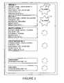
- FIG. 2shows an example of a possible display.
- Monitoring station 12may, for example, be located at a nursing station where it can be used by a duty nurse to monitor the status of patients. Monitoring station 12 may generate alarms if the data signals meet specified alarm criteria.
- the alarm criteriamay include, for example:
- An alarmmay cause a visible indicia 29 to be displayed on display 26 (see FIG. 2 ) and may also or in the alternative cause an audible signal to be generated by alarm 28 which may comprise a buzzer or the like.
- a remote monitoring station(not shown) may be provided in addition to monitoring station 12 .
- Monitoring station 12is optionally in communication with a portable monitoring device such as a pager or the like that can signal to a responsible person when an alarm condition is detected at monitoring station 12 .
- Display 26may display trends in a monitored person's motion as well as any vital signs being monitored as well as values for various vital signs being monitored by system 10 .
- Monitoring station 12may be integrated with an overall patient management system that tracks patient information, treatment history, medication history and the like. Such systems are commercially available and are therefore not described further herein. Personnel at monitoring station 12 can observe the heart and respiration rates of patients being monitored and are warned by an alarm when a patient gets or falls out of bed, a patient stops breathing, a patient's heart stops, a patient is moving abnormally, or there exists some other condition or combination of conditions for which monitoring station 12 provides an alarm.
- Sensing units 14comprise ultra wideband (UWB) radar systems.
- FIG. 3is a block diagram of an example sensing unit 14 .
- Sensing unit 14has a UWB radar system 30 connected to an antenna system 31 .
- UWB radar system 30has a UWB transmitter 30 A, and a UWB receiver 30 B.
- UWB radar system 30generates UWB pulses that are transmitted by antenna system 31 into a space where a person may be located. This space may be called a “sensing volume” since UWB radar system 30 can be used to detect a person in the space. If a person is present in the space then the pulses are reflected at interfaces within the person's body, such as surfaces of the lungs and heart. Reflected pulses are received at antenna 31 and detected by UWB radar 30 .
- the UWB pulsesare in the C-band (3.6 to 4.6 GHz).
- the width of transmitted UWB pulsesmay be in the range of 1 ns to 3 ns, for example.
- UWB pulsesare delivered at a suitable rate.
- the pulse ratemay be set to a value low enough that the average emitted power is low enough to satisfy applicable regulatory requirements.
- the pulse repetition interval (PRI)is in the range of 0.5 ⁇ s to 1 ⁇ s in some embodiments.
- the time-averaged transmitted output powermay be relatively small.
- the maximum effective isotropic radiation power (EIRP)may be ⁇ 41.3 dBm/MHz or less.
- a receiver output signal 32 from UWB radar system 30is passed to a signal processing system 33 .
- Signal processing system 33processes receiver output signal 32 to obtain values for heart rate, breathing rate, and/or other characteristics being monitored by sensing unit 14 .
- An output signal containing values for the characteristicsis passed to wireless communication device 35 which transmits a signal 24 that carries data representing the values to monitoring station 12 by way of antenna 36 .
- a control 38coordinates the operation of sensing unit 14 .
- Control 38may, for example, comprise a programmable microprocessor executing software instructions, logic circuits, or some combination thereof.
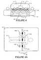
- FIG. 4illustrates schematically how an antenna system 31 located under a mattress 17 can emit a UWB pulse 40 .
- Pulse 40passes into a person P and is reflected at various surfaces, including surfaces of the person's lungs L and heart H, to form reflected pulses 42 that are detected by antenna system 31 .
- the systemcan monitor heart and respiration rates of a person without electrodes or other devices being attached to the body of the person.
- Antenna system 31may comprise an array of transmit antennas 31 A and an array of receive antennas 31 B.
- the transmit and receive antennasare distributed over an area broad enough to be able to cause and detect reflected pulses 42 from patient P in any reasonable position and posture on mattress 16 .
- Transmit antennas 31 Amay be low-gain antennas.
- the use of low-gain transmit antennas 31 Apermits transmission of UWB signals having higher average amplitudes without causing EIRP to exceed thresholds that may be specified by applicable regulations. In some jurisdictions, regulations require that EIRP not exceed a specified threshold value. Further, since low-gain antennas generally have broad radiation patterns the radiation is distributed into a broad angular space.
- Receive antennas 31 Bmay be higher-gain antennas to provide better signal-to-noise ratios (SNR) for received signals containing reflected pulses 42 .
- SNRsignal-to-noise ratios
- FIG. 4Ashows an example arrangement of antenna arrays under mattress 16 .
- a number of transmitting arrays 31 A and receiving arrays 31 Bare arranged in a region 46 extending across mattress 16 at the expected level of the torso of a person P lying on mattress 16 .
- Each transmitting array 31 Ais at the center of a cluster of receiving arrays 31 B.
- each transmitting array 31 Ais at the center of a group of four receiving arrays 31 B that are approximately equally-spaced from a central transmitting array 31 A.
- Arranging transmit antennas 31 A and receive antennas 31 B in an interleaved fashionfacilitates obtaining a good signal-to-noise ratio.
- Transmit antennas 31 Amay be low-gain antennas that provide a relatively large coverage angle. This permits coverage of region 46 with relatively few transmit antennas 31 A.
- FIG. 4Bshows another possible arrangement in which a number of antenna modules 43 each have a number of transmit antennas 31 A and a number of receive antennas 31 B.
- Modules 43may be connected to an electronics module 44 containing a UWB transceiver by suitable waveguides such as coaxial cables 45 .
- Each module 43may be, for example, approximately 8 inches square.
- each module 43has four receiving antennas 31 B and one transmitting antenna 31 A.
- the antennasmay be directly mounted or formed (for example by etching or printing) on a circuit board.
- Each modulemay optionally comprise a four-into-one power combiner to collect power from the receive antennas for delivery to electronics module 44 .
- the apparatus of FIG. 4Bmay be enclosed within a suitable housing for placement under the mattress of a bed.
- the housingprovides insulation of antennas 31 A and 31 B from contact with any dielectric or metallic surface that could affect their performance.
- the housingmay provide an air gap between antenna modules 43 and an underlying mounting surface.
- the housingmay include a solid base plate to which the antenna modules and electronics module may be mounted.
- the base platemay, for example, comprise a sheet of aluminum or other suitable material.
- the housingmay include a radome for environmental protection.
- the radomemay be formed, for example, from a thin layer of plastic.
- a metallic shielding enclosuremay be provided for electronics module 44 .
- FIG. 4Cshows another embodiment which has fewer antennas than the embodiment of FIG. 4B .
- Other arrangements of antennasare also possible.
- UWB transmitter 30 Acomprises an oscillator 50 that is quenched to create a pulsed radiofrequency (RF) waveform that passes into a gated amplifier 52 to produce UWB pulses 40 . It is generally desirable that the center frequency of oscillator 50 be tunable to allow for frequency optimization, if required. Any suitable oscillator circuit may be used in oscillator 50 . A wide range of suitable oscillators are known to those skilled in the art. For example, oscillator 50 may comprise an oscillator based on a diode, FET or junction transistor.
- UWB receiver 30 Breceives a signal 53 from receiving array 31 B of antenna system 31 and passes the received signal through a RF signal conditioning stage 54 that comprises, for example, a filter 55 and an amplifier 56 .
- the conditioned signalis provided to a mixer 58 where it mixes with a signal from oscillator 50 to yield a baseband signal 59 .
- Baseband signal 59is further conditioned in baseband conditioning stage 60 , for example, by a filter 61 and amplifier 62 .
- the conditioned baseband signalis then digitized by analog-to-digital converter (ADC) 64 .
- ADC 64is preferably at least a 12/14-bit ADC so that the conditioned baseband signal can be digitized with 80 dB in dynamic range.
- ADC 64may comprise the ADC part of a combined ADC/microprocessor.
- a coherent Doppler detection schemeis applied to detect reflected pulses 42 .
- the conditioned baseband signalhas a frequency component that varies with a patient's heart beat and a frequency component that varies as the patient breathes.
- the conditioned baseband signalmay be an audio frequency signal (for example, the conditioned baseband signal may have frequencies in the range of a fraction of a Hertz to a few Hertz).
- the digitized signal 65passes to signal processing stage 33 .
- Signal processing stage 33comprises a suitable data processor, such as a digital signal processor or microprocessor, for example, or suitable analog or digital signal processing circuits, such as a suitable configured field-programmable gate array (FPGA).
- FPGAfield-programmable gate array
- signal processing stage 33comprises a digital signal processor (DSP) 66 executing software instructions 68 stored in a program store accessible to DSP 66 .
- DSP 66extracts heart rate and respiration rate information from signal 65 .
- DSP 66is programmed to perform a transformation of the conditioned baseband signal into the frequency domain.
- An example of such a transformationis the Fourier transformation, which may be implemented as a fast Fourier transformation (FFT) algorithm.
- Heart beats in humanstypically have frequencies in the range of 0.8 Hz to 3 Hz (50 to 180 beats per minute). Respiration in humans typically occurs at frequencies in the range of 0.1 Hz to 0.7 Hz (6 to 42 breaths per minute).
- DSP 66can extract the patient's heart and breathing rates by searching in the transformed frequency domain signal for peaks at frequencies in the ranges expected for heart and respiration rates.
- the heart and respiration rate frequency rangesmay be specified in DSP software 68 or stored in a data register accessible to DSP 66 .
- the heart and respiration rate rangesmay be user-configurable. For example, infants may have heart rates that are substantially higher than the heart rates of adults. Where apparatus according to the invention will be used to monitor an infant, the heart and respiration rate frequency ranges may be set to higher values by way of a suitable user interface.
- the accuracy of the resultsmay be improved by performing the transformation into the frequency domain for relatively large blocks of data.
- the transformation into the frequency domainmay be performed by taking 3 or more blocks of conditioned baseband data at a time. Each block may contain, for example, 256, 521 or 1024 samples of the conditioned baseband data. Each time a new block is available, the transformation is repeated by dropping the oldest block and adding the newest block. The data on which each successive transformation is based therefore overlaps with the data for the immediately prior transformation. For example, where 4 blocks of data are taken at a time, there is a 75% overlap in the data used for each transformation.
- DSP 66may be programmed to select the peak that is closest to the previously-determined average heart rate.
- Harmonics of the respiration frequencycan fall in the heart rate frequency range.
- Receiver 30 Bmay be designed to minimize such harmonics.
- DSP 66may be programmed to detect frequency components that are harmonics of the heart rate or respiration rate and to determine the heart rate or respiration rate entirely, or in part from the frequencies of the harmonics.
- the heart ratemay be determined by detecting and measuring the frequency of the second harmonic of the heart rate and dividing the result by two.
- a personcan have a respiration rate that is relatively high and a heart rate that is relatively low. In such cases, it may not be possible to separate the heart rate and respiration rate signals (especially because the signal level of the respiration rate signal is typically much larger than that of the heart rate signal—in some cases the respiration rate signal may be 20 dB to 30 dB higher in amplitude than the heart rate signal).
- This amplitude differencecan be reduced somewhat by providing a filter that reduces the amplitude of the respiration signal in signal conditioning stage 60 .
- signal conditioning stage 60may reduce the amplitude of signals in the respiration frequency range by 10 to 15 dB relative to signals in the heart rate frequency range.
- Identification and measurement of the frequencies of respiration and heart beat signalsmay be enhanced by performing time-domain analysis of the conditioned baseband signal. For example, one can measure the respiration rate by counting peaks and zero-crossings in the conditioned baseband signal (which may be further conditioned by suitable filtering). By filtering out lower frequencies in the conditioned baseband signal one may also measure heart rate by counting peaks in the signal resulting from heart motion. Respiration rate information and/or heart rate information obtained by time domain analysis may be combined with corresponding information obtained by frequency domain analysis to obtain refined estimates of respiration rate and/or heart rate. In the alternative, respiration rate information and/or heart rate information may be obtained by time domain analysis instead of by frequency domain analysis.
- respiration rate and heart ratemay be determined in two or more different ways and a value for the respiration rate or heart rate may be established by combining results obtained in the two or more different ways.
- a system according to the inventionmay include a first means for determining the heart rate by directly identifying a frequency component corresponding to the heart rate in the Fourier transform of the conditioned baseband signal; a second means for determining the heart rate by identifying a frequency component corresponding to the second harmonic of the heart rate in the Fourier transform of the conditioned baseband signal; a third means for determining the heart rate by time-domain analysis of the conditioned baseband signal; and a combining means for combining results provided by the first, second and third means to yield a value for the heart rate.
- the combining meansmay, for example, take an average or a weighted average of the results.
- DSP 66averages the heart and respiration rates over suitable windows and provides updated averages to communication subsystem 35 .
- both the heart rate and respiration ratemay be averaged over a window of 15 to 30 seconds. Since the respiration rate is typically less than the heart rate, respiration rate may optionally be averaged over a longer window. Shorter averaging times may be used initially to reduce the time between power up and the availability of heart rate and respiration rate information.
- DSP 66is preferably programmed to detect such motion artifacts and to generate a signal (for example, by setting a motion-sensing flag) which indicates to monitoring station 12 that motion is detected and the motion is preventing the update of respiration rate and/or heart rate. DSP 66 may detect motion artifacts by identifying large amplitude low-frequency components in the conditioned baseband signal 65 .
- Heart ratesdo not typically change suddenly in comparison to the period of the heart rate.
- Monitoring station 12may perform statistical analysis on the averaged heart rate and breathing rate values. For example, a new heart rate value may be compared to the previous average heart rate value. If the new heart rate value differs by more than a threshold amount (for example, 50%) from the previous average heart rate value then monitoring station 12 (or DSP 66 ) may be configured not to display the new value. In this situation, monitoring station 12 may indicate that the heart rate value is unreliable by displaying a symbol, instead of or in addition to the heart rate value, not displaying the heart rate value, displaying the heart rate value using different display parameters (e.g. flashing, a different color, etc.) or the like.
- a threshold amountfor example, 50%
- Monitoring station 12may monitor heart rate and breathing rate signals for patterns that indicate a potential problem. For example, monitoring station 12 may be configured to trigger an alarm if a person's respiration rate suddenly increases and stays high, either on its own or in combination with other factors.
- FIG. 6shows a circuit 70 that may be used as UWB radar 30 .
- Circuit 70has a signal generation section 70 A and a signal receiving section 70 B.
- Signal generation section 70 Aproduces a local oscillator signal 71 and a UWB pulse signal 72 .
- Signals 71 and 72have different waveforms.
- Signal 72is made up of short UWB pulses having pulse-width of a few nanoseconds (ns).
- Local oscillator signal 71provides pulses that are longer than the pulses in signal 72 with the same carrier frequency as the pulses in signal 72 .
- the length of pulses in local oscillator signal 71should be sufficiently long to allow capture of all reflected pulses 42 in a range of interest. Reflected pulses 42 which arrive after the end of the local oscillator pulse will not be detected. It is desirable to keep pulses in local oscillator signal 71 short to exclude unwanted signals from the surroundings and to avoid unnecessary RF coupling.
- the length of pulses in signal 71is typically in the range of about 5 ns to 10 ns or so and may be adjustable. In some embodiments the pulses in signals 71 and 72 can be of the same or similar lengths.
- a short pulseis generated by SP gating circuit 86 .
- the short pulseoperates switch 82 to pass a very short RF pulse to the transmitting antenna array via filter 88 .
- Keeping transmitted pulses shortimplies that the transmitted pulses will have a relatively broad bandwidth with low average signal level.
- Such low level signalscan be made to meet regulatory requirements, such as requirements imposed by the Federal Communications Commission (FCC) in the United States which limit the allowable time-averaged and maximum signal levels.
- Delay 84allows control over the relative timing between the transmit pulses in signal 72 and local oscillator signal 71 .
- differential amplifier 96 A, amplifier 98 A and filter 99 Acarry a signal from which heart-rate will be determined.
- a separate differential amplifier 96 B, amplifier 98 B and filter 99 Bare provided to condition a signal from which respiration rate will be determined. This facilitates separation of the heart-rate and respiration signals.
- the component of the demodulated signal at the output of mixer 94 that carries information regarding respirationis typically about 20 dB to 30 dB higher in magnitude than the component of the signal that represents heart rate.
- a high pass filter 99 A in the heart rate channelcan filter out much of the respiration signals.
- the high-pass filtermay, for example, filter out signal components that have frequencies less than about 0.5 Hz and pass higher-frequency signals. Separation of the respiration signal from the heart-rate signal allows amplification of the respiration and heart rate signals to levels which facilitate time-domain signal processing of the signals.
- Amplifier 104 and filter 105respectively amplify and low-pass filter a signal taken at the output of mixer 94 . This signal is presented at output 106 . The amplitude of the signal at output 106 increases as the reflected power picked up by receive antennas 31 B increases.
- the signal at output 106will have an amplitude within a given range. In the case of a bed sensor, this indicates that the bed is not occupied. In the case of sensors being used in other applications, this indicates that a person is not present within the sensing volume.
- the reflected power (or reflected power difference) indicated by the signal at output 106changes.
- a system 10may monitor the signal at output 106 and change a status flag from, for example, NOT_OCCUPIED to NORMAL when the signal at output 106 changes to a value outside of the range that it has when no person is present.
- a signal processing system 33may set a status flag based on the combination of signals at outputs 102 and 106 .
- the status flagmay, for example, have values of NOT OCCUPIED, MOTION, and NORMAL. Some embodiments may have status flags for both normal motion and abnormal motion.
- the status flag indicating normal motionmay be set when a person being monitored rolls over or changes position in a way that is normal and expected.
- the status flag indicating abnormal motionmay be set when the person being monitored makes movements that indicate a possible problem that may require intervention.
- the status flag indicating abnormal motionmay be set when the person being monitored makes continued thrashing movements as may accompany certain types of seizure. Updating of heart rate and respiration rate values may be suppressed when the status flag has a value other than “NORMAL”.
- FIG. 7is a timing diagram that illustrates the relative timing between shorter pulse gating signal 87 which controls the timing and lengths of transmitted UWB pulses in signal 72 and longer pulse signal 77 which controls the timing and duration of pulses in local oscillator signal 71 .
- Signal 77has pulses of length A, for example 5-10 ns separated by intervals of length B, for example, about 1 ⁇ s.
- pulses in signal 87begin at time C, typically a few ns, after the initiation of the longer pulse in signal 77 . This promotes frequency and phase stability at the start of the oscillation.
- the pulses in signal 87have lengths D, of a few ns (for example, 1-5 ns and preferably 3 ns or less, for example 1-2 ns).
- the pulse length D and pulse repetition ratemay be chosen to achieve a time-averaged power density that is low enough to comply with limits imposed by applicable regulations.
- Received signals 89will arrive at receiver 70 B in different time slots.
- the pulse length A during which local oscillator signal 71 is availableis sufficiently long to encompass all received signals 89 .
- the received signalis time gated at receiver 70 B by the local oscillator signal.
- Using a local oscillator signal that is longer than the transmitted signalallows the simultaneous detection of signals from all receive antennas. As a result, channel multiplexing is not required.
- the local oscillator signalshould not be unnecessarily long in order to prevent receiver 70 B from receiving unwanted noise signals.
- a blanking signal MPis generated at the start of each transmit pulse SP. Blanking signal MP is connected to suppress the reception of received signals 89 while UWB pulses are being transmitted. This prevents signals induced in the receive antennas by near-field coupling to the transmit antenna(s) from being mistaken for desired received signals 89 .
- a sensing unit 14may be provided to monitor for the presence, respiration rate and/or breathing rate of an infant in a crib or of a person in a bed or chair.
- An alarmmay be integrated with sensing unit 14 or the sensing unit 14 may be connected to communicate an alarm signal to a remote alarm unit (either by way of a wired or wireless connection).
- a sensing unit 14is combined with a baby monitor.
- a base station of the baby monitorreceives sounds made by an infant and also delivers an alarm signal in case the output from sensor 14 indicates a possible problem (such as the infant has stopped breathing).
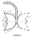
- FIGS. 8 , 8 A and 8 Bshow a design for an antenna array 120 that may be used in a system of the type described herein and may also be used for other applications. Individual antennas of the type shown in FIG. 8B may be combined into arrays of other types or used in stand-alone applications.
- Array 120comprises a plurality of dipole-like antennas disposed on a planar substrate 121 such as a circuit board.
- Substrate 121may comprise a two-sided copper-clad laminate in which the copper cladding has been patterned as shown in FIG. 8 .
- twelve receive antennas 122are interconnected by waveguides 123 .
- Receive antennas 122are located at nodes of a rectangular grid.
- Two-way signal combiners 126combine signals from all of receive antennas 122 into a single output 128 .
- a transmit antenna 130is located in the centre of array 120 . When array 120 is positioned at a proper height above a ground plane, both transmit antennas 120 and receive antennas 130 have directional radiation patterns.
- Each antenna 122 and 130has elements 124 A and 124 B that extend in opposite directions on opposite faces of substrate 121 .
- a single antenna 122is shown in detail in FIG. 8B .
- Elements 124 A and 124 Bare mirror images of one another and are each symmetrical about a centre line 131 .
- Each element 124 Ahas a rounded segment 132 in the vicinity of its feed point 133 and a number of stubs of unequal length on its open end.
- rounded segment 132merges into straight diverging edge segments 134 which extend to corners 136 of outer stubs 137 .
- the open end of the element 124is W-shaped.
- Straight segments 138form acute angles at corners 136 .
- a central stub 140is defined between substantially straight segments 142 which meet at a corner 144 . In the illustrated embodiment, corner 144 is approximately a right angle.
- the resonant frequencies of antenna 122 or 130are determined primarily by the effective length of elements 124 in the Z-direction (i.e. in a direction parallel to line 131 ). Broad frequency bandwidth is achieved by providing a curved geometry near feed point 133 and multiple (three in the illustrated example) stubs of different lengths at the open end of the element. This geometry allows resonances at multiple frequencies due to its varying effective element length. In some embodiments, over 30% of frequency bandwidth can be achieved with or without use of a reflective ground plane.
- each antenna 122 or 130can be adjusted by varying the subtended angle, ⁇ (see FIG. 8 ) between segments 134 .
- the bandwidthincreases as the subtended angle is increased and decreases as the subtended angle is decreased.
- the input impedance of radiating elements 124is matched to a 50 ohm unbalanced microstrip transmission line 123 through a pair of balanced strip lines 150 of constant width.
- the antenna 122 or 130can be matched to a 50 ohm unbalanced transmission line without any additional matching network.
- UWB radarmay be used to detect the presence, movement, heart and respiration rates of a person sitting in a chair.
- a sensing unit for use on a chair back, as a sensor to be strapped-onto a person's chest or back, as a sensor to be used in conjunction with a baby crib, or in similar applicationsdoes not need to cover a field as large as a sensing unit for use in a full-sized bed. Consequently, a sensing unit for such an application may be made to have fewer antennas than would be required to cover a full-sized bed.
- a sensing unit for sensing the presence, heart rate, and/or respiration rate of an infant in a small cribdoes not need to cover a large field and may have only one antenna or just a few antennas.
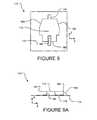
- FIGS. 9 , 9 A, 9 B and 9 Cshow a compact antenna 170 .
- Antenna 170comprises a radiating element 172 that can be mounted directly to a circuit board, for example, by soldering, attachment using an electrically-conductive adhesive, or the like.
- Antenna 170may be used in a sensing unit as described herein or may be used in other applications.
- an electronics module containing UWB radarcomprises a circuit board to which a radiating element 172 can be attached to provide an antenna 170 .
- the circuit boardmay also comprise locations to which waveguides can connect external antennas or antenna arrays.
- a radiating element 172 or one or more external antennas or antenna arraysmay be connected to the circuit board. This permits the same circuit board to be used in sensing units of various types. For example, a number of antenna arrays can be connected to the circuit board for use as an in-bed sensor while a radiating element 172 can be connected to the circuit board for use as a sensor in a chair back, under the mattress of a baby crib, or the like.
- Antenna 170radiates linearly polarized E-fields through the narrow gaps 178 between the radiating element and the ground plane 174 .
- the resonant frequencies of the antennaare primarily determined by the overall dimensions of antenna 170 in the X and Z directions.
- a small stub 180 extended above the open end 182 of radiating element 172can be provided to fine tune the resonant frequencies of antenna 170 .
- the characteristics of antenna 170may also be altered by providing a dielectric material between radiating element 172 and ground plane 174 .
- antenna 170The geometry and dimension of antenna 170 in the Y direction determines the frequency bandwidth of antenna 170 .
- Triangular shapes 184 of the geometry at both sides of antenna 170allow for broadband frequency of operation. Over 20% of frequency bandwidth can be achieved with a proper shaping.
- Some embodiments of antenna 170have a cardioid radiation pattern with directivity between 6 dBi to 8 dBi, depending on the size of ground plane 174 .
- An input feed point 188is recessed into antenna 170 .
- antenna 170can be directly matched to a 50 ohm transmission line without an additional matching network.
- antenna 170may have a radiating gap 178 of about 1 mm and a distance between the top of the radiating element 172 and ground plane 174 in the range of about 5 mm to 6 mm.
- Certain implementations of the inventioncomprise computer processors which execute software instructions which cause the processors to perform a method of the invention.
- processors in a sensing unit or a combination of processors in sensing units and a monitoring stationmay implement the methods for obtaining heart rate and breathing rate information that are described herein by executing software instructions in a program memory accessible to the processors.
- the inventionmay also be provided in the form of a program product.
- the program productmay comprise any medium which carries a set of computer-readable signals comprising instructions which, when executed by a data processor, cause the data processor to execute a method of the invention.
- Program products according to the inventionmay be in any of a wide variety of forms.
Landscapes
- Health & Medical Sciences (AREA)
- Life Sciences & Earth Sciences (AREA)
- Engineering & Computer Science (AREA)
- Physics & Mathematics (AREA)
- Heart & Thoracic Surgery (AREA)
- Animal Behavior & Ethology (AREA)
- Biophysics (AREA)
- Pathology (AREA)
- Veterinary Medicine (AREA)
- Biomedical Technology (AREA)
- Molecular Biology (AREA)
- Public Health (AREA)
- Medical Informatics (AREA)
- Surgery (AREA)
- General Health & Medical Sciences (AREA)
- Radar, Positioning & Navigation (AREA)
- Remote Sensing (AREA)
- Physiology (AREA)
- Pulmonology (AREA)
- Computer Networks & Wireless Communication (AREA)
- Cardiology (AREA)
- Oral & Maxillofacial Surgery (AREA)
- Dentistry (AREA)
- General Physics & Mathematics (AREA)
- Signal Processing (AREA)
- Psychiatry (AREA)
- Computer Vision & Pattern Recognition (AREA)
- Artificial Intelligence (AREA)
- Nuclear Medicine, Radiotherapy & Molecular Imaging (AREA)
- Radiology & Medical Imaging (AREA)
- Measuring And Recording Apparatus For Diagnosis (AREA)
- Measurement Of The Respiration, Hearing Ability, Form, And Blood Characteristics Of Living Organisms (AREA)
- Variable-Direction Aerials And Aerial Arrays (AREA)
- Radar Systems Or Details Thereof (AREA)
- Emergency Alarm Devices (AREA)
- Alarm Systems (AREA)
- Arrangements For Transmission Of Measured Signals (AREA)
Abstract
Description
- Newham, U.S. Pat. No. 5,471,198 and Edwards, U.S. Pat. No. 6,788,206 which disclose systems for monitoring for the presence of persons using reflected energy.
- Richards et al., U.S. Pat. No. 6,900,732 which discloses a system for monitoring assets, objects, persons or animals using UWB signals.
- Richards et al., U.S. Pat. No. 6,466,125 which discloses a system, electronic monitor and method that utilize impulse radio technology to alert medical personnel when a patient needs medical assistance.
- Richards et al., U.S. Pat. No. 6,504,483 which discloses the use of impulse radio to track a position of a horse as it moves around a race track and/or to enable people to monitor one or more vital signs of the moving horse. The patent discloses that the technology may also work with other animals, such as dogs, and with people.
- Hall et al., U.S. Pat. No. 6,661,342 which discloses the use of impulse radio to track moving athletes and to provide secure communication with athletes.
- Nowogrodzki et al., U.S. Pat. No. 4,513,748 which discloses a heart rate monitor that utilizes two RF signals.
- Bloice, U.S. Pat. No. 3,796,208 which discloses a system for monitoring movements of a patient using a microwave radar unit.
- Lye et al, WO 2004/047630 which discloses a system that uses UWB signals to transmit information regarding the health condition of a user.
- Tupin et al. US 2004/0249258 which discloses the use of UWB radar for imaging and acquiring physiological data.
- McEwan, U.S. Pat. No. 5,361,070, which discloses a UWB radar motion sensor.
- Edwards, U.S. Pat. No. 6,788,206 discloses a patient monitoring system.
- a heart rate of the person;
- a breathing rate of the person;
- whether a person's breathing or heart beat has stopped;
- whether a person's breathing or heart beat has an abnormal pattern;
- whether or not the person is active (i.e. moving);
- whether a person is moving in an unusual way (e.g. whether the person is moving in a manner that could indicate a seizure or fit)
- whether or not a person is present in the vicinity of the sensing unit; and,
- the like.
Data signals24 that contain results from the monitoring operation are transmitted tomonitoring station 12.
- a person is present but has not moved and has not had a detectable heart beat or respiration for more than a threshold period;
- a person who should remain present at a
sensing unit 14 is no longer detected as being present; - a person is detected in a restricted area; and,
- the like.
- antennas having features of antennas like those in
FIGS. 8 ,8A and8B that may be applied for any purpose; - antennas having features of an antenna like the one shown in
FIGS. 9 ,9A and9B that may be applied for any purpose; - monitoring systems that may be used for monitoring the presence, heart rate and/or respiration rate of one or more persons of which the system of
FIG. 1 is an example; - monitoring systems that may be used to monitor the well being of an infant or single person—examples of such systems include baby monitors and systems for waking a person who suffers from sleep apnea if the person stops breathing for more than a short time; and,
- sensors based on UWB radar that may be used to monitor for the presence, heart rate and/or respiration rate of a person. Such sensors may be used, for example, by emergency personnel (e.g. firefighters, ambulance attendants, emergency response technicians, military medics or the like) to test for the presence of vital signs in injured or unwell people. Such sensors may be portable. In some embodiments the sensors are configured to be pressed against the back or chest of a person and include a display or other indicator that identifies whether or not vital signs (e.g. heat beat and/or breathing) can be detected and may provide information such as heart rate and breathing rate.
- sensors based on UWB radar that may be used to detect a pulse at a location on an individual. Such sensors may be used, for example, in non-invasive blood pressure monitors which compute blood pressure of an individual based upon the speed of propagation of pulses in the individual's circulatory system. Such sensors may be provided, for example, at a person's neck and ankle. The difference in the time at which a pulse is detected at these two locations may be correlated to the individual's blood pressure. Two such sensors may be connected to a controller that determines a difference in time between the arrival of pulses at the sensors and computes a blood pressure or a change in a blood pressure based at least in part on that time difference.
- antennas having features of antennas like those in
- In some embodiments transmit pulses are distributed among several transmit antennas such that the transmit antennas transmit UWB pulses in different time slots. In each of the time slots reflected pulses may be detected at a plurality of receive antennas. In some embodiments, this is achieved by distributing transmit signals to each of several antennas which are placed at various locations and are separated from the UWB transmitter by different RF path lengths.
- In some of the implementations described above, a switched amplifier is used for
RF switch 82. However, a suitable RF switch can also be implemented using other technologies such as PIN diodes, Schottky Diodes, micro-electro-mechanical (MEM) switches and the like. - Some embodiments which are designed for short range lack a
switch 82.
Accordingly, the scope of the invention is to be construed in accordance with the substance defined by the following claims.
Claims (70)
Priority Applications (1)
| Application Number | Priority Date | Filing Date | Title |
|---|---|---|---|
| US12/281,146US8428696B2 (en) | 2006-03-06 | 2007-03-06 | Ultra wideband monitoring systems and antennas |
Applications Claiming Priority (3)
| Application Number | Priority Date | Filing Date | Title |
|---|---|---|---|
| US77890806P | 2006-03-06 | 2006-03-06 | |
| PCT/CA2007/000365WO2007101343A1 (en) | 2006-03-06 | 2007-03-06 | Ultra wideband monitoring systems and antennas |
| US12/281,146US8428696B2 (en) | 2006-03-06 | 2007-03-06 | Ultra wideband monitoring systems and antennas |
Related Parent Applications (1)
| Application Number | Title | Priority Date | Filing Date |
|---|---|---|---|
| PCT/CA2007/000365A-371-Of-InternationalWO2007101343A1 (en) | 2006-03-06 | 2007-03-06 | Ultra wideband monitoring systems and antennas |
Related Child Applications (1)
| Application Number | Title | Priority Date | Filing Date |
|---|---|---|---|
| US13/851,287ContinuationUS8781563B2 (en) | 2006-03-06 | 2013-03-27 | Ultra wideband monitoring systems and antennas |
Publications (2)
| Publication Number | Publication Date |
|---|---|
| US20090227882A1 US20090227882A1 (en) | 2009-09-10 |
| US8428696B2true US8428696B2 (en) | 2013-04-23 |
Family
ID=38474570
Family Applications (3)
| Application Number | Title | Priority Date | Filing Date |
|---|---|---|---|
| US12/281,146Active - Reinstated2029-12-14US8428696B2 (en) | 2006-03-06 | 2007-03-06 | Ultra wideband monitoring systems and antennas |
| US13/851,287ActiveUS8781563B2 (en) | 2006-03-06 | 2013-03-27 | Ultra wideband monitoring systems and antennas |
| US14/299,161ActiveUS10517503B2 (en) | 2006-03-06 | 2014-06-09 | Ultra wideband monitoring systems and antennas |
Family Applications After (2)
| Application Number | Title | Priority Date | Filing Date |
|---|---|---|---|
| US13/851,287ActiveUS8781563B2 (en) | 2006-03-06 | 2013-03-27 | Ultra wideband monitoring systems and antennas |
| US14/299,161ActiveUS10517503B2 (en) | 2006-03-06 | 2014-06-09 | Ultra wideband monitoring systems and antennas |
Country Status (6)
| Country | Link |
|---|---|
| US (3) | US8428696B2 (en) |
| EP (1) | EP1996068A4 (en) |
| JP (1) | JP5312053B2 (en) |
| KR (1) | KR101414586B1 (en) |
| CN (2) | CN102512148A (en) |
| WO (1) | WO2007101343A1 (en) |
Cited By (49)
| Publication number | Priority date | Publication date | Assignee | Title |
|---|---|---|---|---|
| US20100152543A1 (en)* | 2008-09-24 | 2010-06-17 | Biancamed Ltd. | Contactless and minimal-contact monitoring of quality of life parameters for assessment and intervention |
| US20100179438A1 (en)* | 2006-11-01 | 2010-07-15 | Biancamed Limited | System and method for monitoring cardiorespiratory parameters |
| US20100204550A1 (en)* | 2009-02-06 | 2010-08-12 | Biancamed Limited | Apparatus, system and method for chronic disease monitoring |
| US20150002331A1 (en)* | 2013-07-01 | 2015-01-01 | Siemens Aktiengesellschaft | Radar system for medical use |
| US9370457B2 (en) | 2013-03-14 | 2016-06-21 | Select Comfort Corporation | Inflatable air mattress snoring detection and response |
| US9392879B2 (en) | 2013-03-14 | 2016-07-19 | Select Comfort Corporation | Inflatable air mattress system architecture |
| US9445751B2 (en) | 2013-07-18 | 2016-09-20 | Sleepiq Labs, Inc. | Device and method of monitoring a position and predicting an exit of a subject on or from a substrate |
| US9468399B2 (en)* | 2014-12-09 | 2016-10-18 | SensaRx, LLC | Detection of changes from a seated or lying body position by sensing body angle |
| US9504416B2 (en) | 2013-07-03 | 2016-11-29 | Sleepiq Labs Inc. | Smart seat monitoring system |
| US9510688B2 (en) | 2013-03-14 | 2016-12-06 | Select Comfort Corporation | Inflatable air mattress system with detection techniques |
| US9629340B2 (en) | 2014-02-24 | 2017-04-25 | Equus Global Holdings Llc | Mobile animal surveillance and distress monitoring |
| US9635953B2 (en) | 2013-03-14 | 2017-05-02 | Sleepiq Labs Inc. | Inflatable air mattress autofill and off bed pressure adjustment |
| US9770114B2 (en) | 2013-12-30 | 2017-09-26 | Select Comfort Corporation | Inflatable air mattress with integrated control |
| US9844275B2 (en) | 2013-03-14 | 2017-12-19 | Select Comfort Corporation | Inflatable air mattress with light and voice controls |
| US9910147B2 (en)* | 2014-02-04 | 2018-03-06 | Furuno Electric Co., Ltd. | Radar antenna |
| US10058467B2 (en) | 2013-03-14 | 2018-08-28 | Sleep Number Corporation | Partner snore feature for adjustable bed foundation |
| US10092242B2 (en) | 2015-01-05 | 2018-10-09 | Sleep Number Corporation | Bed with user occupancy tracking |
| US10149549B2 (en) | 2015-08-06 | 2018-12-11 | Sleep Number Corporation | Diagnostics of bed and bedroom environment |
| US10154655B2 (en) | 2014-02-24 | 2018-12-18 | Equus Global Holdings Llc | Mobile animal surveillance and distress monitoring |
| EP3428675A1 (en)* | 2017-07-12 | 2019-01-16 | Hill-Rom Services, Inc. | Patient support surface using radar |
| US10182661B2 (en) | 2013-03-14 | 2019-01-22 | Sleep Number Corporation and Select Comfort Retail Corporation | Inflatable air mattress alert and monitoring system |
| US10401479B2 (en) | 2014-05-16 | 2019-09-03 | University Of Ottawa | Remote sensing of human breathing at a distance |
| WO2019186333A1 (en)* | 2018-03-26 | 2019-10-03 | Diagnostic Robotics Ltd. | Measurement of physiological parameters |
| US10448749B2 (en) | 2014-10-10 | 2019-10-22 | Sleep Number Corporation | Bed having logic controller |
| US10492720B2 (en) | 2012-09-19 | 2019-12-03 | Resmed Sensor Technologies Limited | System and method for determining sleep stage |
| US10660563B2 (en) | 2012-09-19 | 2020-05-26 | Resmed Sensor Technologies Limited | System and method for determining sleep stage |
| US10674832B2 (en) | 2013-12-30 | 2020-06-09 | Sleep Number Corporation | Inflatable air mattress with integrated control |
| US10729332B2 (en) | 2006-06-01 | 2020-08-04 | Resmed Sensor Technologies Limited | Apparatus, system, and method for monitoring physiological signs |
| US10912693B2 (en) | 2017-07-12 | 2021-02-09 | Hill-Rom Services, Inc. | Patient immersion and support surface life determination using RADAR and RFID |
| US10989806B2 (en) | 2017-03-08 | 2021-04-27 | Praesidium, Inc. | Home occupant detection and monitoring system |
| US11273283B2 (en) | 2017-12-31 | 2022-03-15 | Neuroenhancement Lab, LLC | Method and apparatus for neuroenhancement to enhance emotional response |
| US11364361B2 (en) | 2018-04-20 | 2022-06-21 | Neuroenhancement Lab, LLC | System and method for inducing sleep by transplanting mental states |
| US11439345B2 (en) | 2006-09-22 | 2022-09-13 | Sleep Number Corporation | Method and apparatus for monitoring vital signs remotely |
| US11450192B2 (en) | 2020-01-06 | 2022-09-20 | National Cheng Kung University | Fall detection system |
| US11452839B2 (en) | 2018-09-14 | 2022-09-27 | Neuroenhancement Lab, LLC | System and method of improving sleep |
| US11633122B2 (en) | 2018-07-09 | 2023-04-25 | Neteera Technologies Ltd. | Portable sub-THz and THz radar system for remote physiological parameters detection and method with harmonic and fundamental components |
| US11717686B2 (en) | 2017-12-04 | 2023-08-08 | Neuroenhancement Lab, LLC | Method and apparatus for neuroenhancement to facilitate learning and performance |
| US11723579B2 (en) | 2017-09-19 | 2023-08-15 | Neuroenhancement Lab, LLC | Method and apparatus for neuroenhancement |
| US11737938B2 (en) | 2017-12-28 | 2023-08-29 | Sleep Number Corporation | Snore sensing bed |
| US11747463B2 (en) | 2021-02-25 | 2023-09-05 | Cherish Health, Inc. | Technologies for tracking objects within defined areas |
| US11786694B2 (en) | 2019-05-24 | 2023-10-17 | NeuroLight, Inc. | Device, method, and app for facilitating sleep |
| US11877844B2 (en) | 2020-02-19 | 2024-01-23 | Hill-Rom Services, Inc. | Respiration detection using radar |
| US11918330B2 (en) | 2017-03-08 | 2024-03-05 | Praesidium, Inc. | Home occupant detection and monitoring system |
| US20240164654A1 (en)* | 2022-11-17 | 2024-05-23 | Fujitsu Component Limited | Detection device and detection system |
| US12042268B2 (en) | 2020-03-31 | 2024-07-23 | Hill-Rom Services, Inc. | Patient body monitoring using radar |
| US12171529B2 (en) | 2018-07-17 | 2024-12-24 | Ohio State Innovation Foundation | Mobile ultrawideband radar for monitoring thoracic fluid levels and cardio-respiratory function |
| US12280219B2 (en) | 2017-12-31 | 2025-04-22 | NeuroLight, Inc. | Method and apparatus for neuroenhancement to enhance emotional response |
| US12390379B2 (en) | 2017-12-28 | 2025-08-19 | Sleep Number Corporation | Bed having snore detection feature |
| US12440111B2 (en) | 2024-02-14 | 2025-10-14 | Resmed Sensor Technologies Limited | Apparatus, system and method for chronic disease monitoring |
Families Citing this family (168)
| Publication number | Priority date | Publication date | Assignee | Title |
|---|---|---|---|---|
| US8463361B2 (en) | 2007-05-24 | 2013-06-11 | Lifewave, Inc. | System and method for non-invasive instantaneous and continuous measurement of cardiac chamber volume |
| ES2664239T3 (en) | 2007-09-05 | 2018-04-18 | Sensible Medical Innovations Ltd. | Method and apparatus for using electromagnetic radiation to monitor a user's tissue |
| US8382667B2 (en) | 2010-10-01 | 2013-02-26 | Flint Hills Scientific, Llc | Detecting, quantifying, and/or classifying seizures using multimodal data |
| US8571643B2 (en) | 2010-09-16 | 2013-10-29 | Flint Hills Scientific, Llc | Detecting or validating a detection of a state change from a template of heart rate derivative shape or heart beat wave complex |
| US8337404B2 (en) | 2010-10-01 | 2012-12-25 | Flint Hills Scientific, Llc | Detecting, quantifying, and/or classifying seizures using multimodal data |
| FI121453B (en) | 2008-02-26 | 2010-11-30 | Finsor Oy | Detection of heart rate |
| US8352015B2 (en)* | 2008-05-27 | 2013-01-08 | Kyma Medical Technologies, Ltd. | Location tracking of a metallic object in a living body using a radar detector and guiding an ultrasound probe to direct ultrasound waves at the location |
| US8989837B2 (en)* | 2009-12-01 | 2015-03-24 | Kyma Medical Technologies Ltd. | Methods and systems for determining fluid content of tissue |
| US9265438B2 (en) | 2008-05-27 | 2016-02-23 | Kyma Medical Technologies Ltd. | Locating features in the heart using radio frequency imaging |
| US8696565B2 (en) | 2008-06-03 | 2014-04-15 | General Electric Company | Patient monitoring system with health status indicator |
| US10667715B2 (en)* | 2008-08-20 | 2020-06-02 | Sensible Medical Innovations Ltd. | Methods and devices of cardiac tissue monitoring and analysis |
| DE102008057977A1 (en)* | 2008-11-19 | 2010-05-20 | Rohde & Schwarz Gmbh & Co. Kg | Device for monitoring health conditions of patient in intensive care unit, has evaluating device for storing received microwave signals as reference microwave signals and later as set of monitoring microwave signals |
| DE102009005110B3 (en)* | 2009-01-19 | 2010-11-18 | Siemens Aktiengesellschaft | Motion detection using the UWB radar system during particle therapy irradiation |
| EP2403401B1 (en) | 2009-03-04 | 2017-05-10 | Sensible Medical Innovations Ltd. | System for monitoring intrabody tissues |
| US9002427B2 (en) | 2009-03-30 | 2015-04-07 | Lifewave Biomedical, Inc. | Apparatus and method for continuous noninvasive measurement of respiratory function and events |
| US20100274145A1 (en) | 2009-04-22 | 2010-10-28 | Tupin Jr Joe Paul | Fetal monitoring device and methods |
| US8907682B2 (en) | 2009-07-30 | 2014-12-09 | Sensible Medical Innovations Ltd. | System and method for calibration of measurements of interacted EM signals in real time |
| WO2011044408A2 (en)* | 2009-10-08 | 2011-04-14 | The Regents Of The University Of Michigan | Real-time visual alert display |
| US8936555B2 (en)* | 2009-10-08 | 2015-01-20 | The Regents Of The University Of Michigan | Real time clinical decision support system having linked references |
| US8430817B1 (en) | 2009-10-15 | 2013-04-30 | Masimo Corporation | System for determining confidence in respiratory rate measurements |
| US9848800B1 (en)* | 2009-10-16 | 2017-12-26 | Masimo Corporation | Respiratory pause detector |
| WO2011092814A1 (en)* | 2010-01-28 | 2011-08-04 | トヨタ自動車株式会社 | Obstacle detection device |
| US9307928B1 (en) | 2010-03-30 | 2016-04-12 | Masimo Corporation | Plethysmographic respiration processor |
| US8562536B2 (en) | 2010-04-29 | 2013-10-22 | Flint Hills Scientific, Llc | Algorithm for detecting a seizure from cardiac data |
| US8831732B2 (en) | 2010-04-29 | 2014-09-09 | Cyberonics, Inc. | Method, apparatus and system for validating and quantifying cardiac beat data quality |
| US8649871B2 (en) | 2010-04-29 | 2014-02-11 | Cyberonics, Inc. | Validity test adaptive constraint modification for cardiac data used for detection of state changes |
| US9220420B2 (en) | 2010-07-21 | 2015-12-29 | Kyma Medical Technologies Ltd. | Implantable dielectrometer |
| US8641646B2 (en) | 2010-07-30 | 2014-02-04 | Cyberonics, Inc. | Seizure detection using coordinate data |
| JP5918234B2 (en)* | 2010-08-02 | 2016-05-18 | ライフウェーブ,インコーポレーテッド | Impedance transformer pad and patient monitoring system using the same |
| EP2417908A1 (en)* | 2010-08-12 | 2012-02-15 | Philips Intellectual Property & Standards GmbH | Device, system and method for measuring vital signs |
| EP2619733B1 (en)* | 2010-09-22 | 2014-02-26 | Koninklijke Philips N.V. | Method and device for identifying a subject in a sensor based monitoring system |
| US12383190B2 (en) | 2011-03-04 | 2025-08-12 | Flint Hills Scientific, Llc | Detecting, assessing and managing extreme seizure events |
| US8684921B2 (en) | 2010-10-01 | 2014-04-01 | Flint Hills Scientific Llc | Detecting, assessing and managing epilepsy using a multi-variate, metric-based classification analysis |
| CN102038494B (en)* | 2010-10-29 | 2012-05-16 | 江苏瑞蚨通软件科技有限公司(中外合资) | Safety guarantee system for high-risk places of digital wireless sensor network |
| JP5788963B2 (en)* | 2011-02-21 | 2015-10-07 | パナソニック インテレクチュアル プロパティ コーポレーション オブアメリカPanasonic Intellectual Property Corporation of America | Data processing apparatus, data processing system, and data processing method |
| EP2678709B1 (en) | 2011-02-21 | 2018-03-28 | Transrobotics, Inc. | System and method for sensing distance and/or movement |
| CN103476334A (en)* | 2011-02-22 | 2013-12-25 | 纽默松尼克斯公司 | Planar antenna device and structure |
| US9504390B2 (en) | 2011-03-04 | 2016-11-29 | Globalfoundries Inc. | Detecting, assessing and managing a risk of death in epilepsy |
| SE535666C2 (en)* | 2011-03-11 | 2012-10-30 | Totalfoersvarets Forskningsins | Method and apparatus for crawling racial masses |
| US20120245479A1 (en)* | 2011-03-23 | 2012-09-27 | Meena Ganesh | Physiology Monitoring and Alerting System and Process |
| US8725239B2 (en) | 2011-04-25 | 2014-05-13 | Cyberonics, Inc. | Identifying seizures using heart rate decrease |
| US9402550B2 (en) | 2011-04-29 | 2016-08-02 | Cybertronics, Inc. | Dynamic heart rate threshold for neurological event detection |
| CN102835958A (en)* | 2011-06-20 | 2012-12-26 | 山东省普来特能源与电器研究院 | Human vital sign remote monitoring device |
| CN102288174B (en)* | 2011-06-22 | 2012-07-11 | 中核能源科技有限公司 | Method and system for determining working path based on radiation dosage of nuclear island |
| TW201300092A (en)* | 2011-06-27 | 2013-01-01 | Seda Chemical Products Co Ltd | Automated snore stopping bed system |
| JP6066637B2 (en)* | 2011-09-21 | 2017-01-25 | ゼネラル・エレクトリック・カンパニイ | System for monitoring the physiological status of multiple infants |
| US9549677B2 (en) | 2011-10-14 | 2017-01-24 | Flint Hills Scientific, L.L.C. | Seizure detection methods, apparatus, and systems using a wavelet transform maximum modulus algorithm |
| CN102512170A (en)* | 2011-10-27 | 2012-06-27 | 中国人民解放军第四军医大学 | Carrying type small radar life detection instrument |
| DE102012101062A1 (en)* | 2012-02-09 | 2013-08-14 | Gira Giersiepen Gmbh & Co. Kg | "Method and sensor system for sensory room monitoring" |
| US9492099B2 (en) | 2012-03-19 | 2016-11-15 | Advanced Telesensors, Inc. | System and method for facilitating reflectometric detection of physiologic activity |
| US10448839B2 (en) | 2012-04-23 | 2019-10-22 | Livanova Usa, Inc. | Methods, systems and apparatuses for detecting increased risk of sudden death |
| WO2013181376A1 (en) | 2012-05-31 | 2013-12-05 | Lifewave, Inc. | Medical radar system for guiding cardiac resuscitation |
| US8797167B2 (en) | 2012-08-24 | 2014-08-05 | Elwha Llc | Computational systems and methods for monitoring medication events |
| US9035777B2 (en) | 2012-08-24 | 2015-05-19 | Elwha Llc | Computational systems and methods for monitoring medication events including use of a camera and data comparison |
| US9081885B2 (en) | 2012-08-24 | 2015-07-14 | Elwha Llc | Computational systems and methods for monitoring medication events including a camera and identified time intervals |
| WO2014042918A2 (en)* | 2012-09-13 | 2014-03-20 | 3M Innovative Properties Company | Antenna system and method for defining a detection zone |
| EP3828591A1 (en) | 2012-10-05 | 2021-06-02 | Transrobotics, Inc. | Systems and methods for high resolution distance sensing and applications |
| JPWO2014061239A1 (en)* | 2012-10-17 | 2016-09-05 | アルプス電気株式会社 | Communication sensor device |
| KR101380788B1 (en)* | 2012-10-19 | 2014-04-04 | 한국과학기술연구원 | Lung cancer diagnostic device using pulsed wave and method of the same |
| CN102961165A (en)* | 2012-12-06 | 2013-03-13 | 中国人民解放军第四军医大学 | Audio life parameter probe based on ultra wide band radar |
| CN103006223A (en)* | 2012-12-13 | 2013-04-03 | 中国人民解放军第四军医大学 | Household non-contact sleeping monitoring device and method |
| CN103006225A (en)* | 2013-01-11 | 2013-04-03 | 湖南纳雷科技有限公司 | Sleep monitoring instrument capable of monitoring breathing state in sleep |
| US9323380B2 (en) | 2013-01-16 | 2016-04-26 | Blackberry Limited | Electronic device with touch-sensitive display and three-dimensional gesture-detection |
| US9335922B2 (en)* | 2013-01-16 | 2016-05-10 | Research In Motion Limited | Electronic device including three-dimensional gesture detecting display |
| US10220211B2 (en) | 2013-01-22 | 2019-03-05 | Livanova Usa, Inc. | Methods and systems to diagnose depression |
| US10441181B1 (en) | 2013-03-13 | 2019-10-15 | Masimo Corporation | Acoustic pulse and respiration monitoring system |
| WO2014176190A1 (en)* | 2013-04-25 | 2014-10-30 | Covidien Lp | System and method for generating an adjusted fluid responsiveness metric |
| US9867540B2 (en)* | 2013-08-09 | 2018-01-16 | Senseonics, Incorporated | Co-planar, near field communication telemetry link for an analyte sensor |
| US10680324B2 (en) | 2013-10-29 | 2020-06-09 | Zoll Medical Israel Ltd. | Antenna systems and devices and methods of manufacture thereof |
| US20150172893A1 (en)* | 2013-12-12 | 2015-06-18 | Gerard St. Germain | Mobile Companion |
| US11013420B2 (en) | 2014-02-05 | 2021-05-25 | Zoll Medical Israel Ltd. | Systems, apparatuses and methods for determining blood pressure |
| US10401477B2 (en)* | 2014-02-25 | 2019-09-03 | University Of Florida Research Foundation, Inc. | Method and apparatus for doppler radar signal recovery of target displacement |
| JP6357623B2 (en)* | 2014-03-28 | 2018-07-18 | エコナビスタ株式会社 | Information processing apparatus, program, and information processing method |
| RS20140247A1 (en)* | 2014-05-14 | 2015-12-31 | Novelic D.O.O. | Radar sensor operating in millimetre wave frequency range for detection of signs of life and method of its operation |
| EP3154423A4 (en)* | 2014-06-11 | 2018-02-07 | Cardiac Motion, LLC | Portable heart motion monitor |
| WO2016009315A1 (en)* | 2014-07-14 | 2016-01-21 | Sensifree Ltd. | Systems and methods for contactless arterial pressure estimator |
| US11169988B2 (en) | 2014-08-22 | 2021-11-09 | Google Llc | Radar recognition-aided search |
| US11020601B2 (en)* | 2014-08-27 | 2021-06-01 | Vladimir Shusterman | Accessory for external cardiac defibrillation, pacing and monitoring physiological signals/health data in the presence of electromagnetic interference |
| US10842440B2 (en)* | 2014-08-27 | 2020-11-24 | Vladimir Shusterman | System and method for monitoring and wirelessly transmitting health data |
| US11207028B2 (en)* | 2014-08-27 | 2021-12-28 | Vladimir Shusterman | Method and system for monitoring physiological signals/health data, defibrillation, and pacing in the presence of electromagnetic interference |
| US11259715B2 (en) | 2014-09-08 | 2022-03-01 | Zoll Medical Israel Ltd. | Monitoring and diagnostics systems and methods |
| US20160089052A1 (en)* | 2014-09-26 | 2016-03-31 | Industry-University Cooperation Foundation Hanyang University | Method and device for measuring biometric data using uwb radar |
| US9600080B2 (en)* | 2014-10-02 | 2017-03-21 | Google Inc. | Non-line-of-sight radar-based gesture recognition |
| US10687729B2 (en) | 2014-11-24 | 2020-06-23 | Koninklijke Philips N.V. | Apparatus and method for estimating a value of a physiological characteristic |
| US10548485B2 (en) | 2015-01-12 | 2020-02-04 | Zoll Medical Israel Ltd. | Systems, apparatuses and methods for radio frequency-based attachment sensing |
| US10216905B2 (en)* | 2015-01-28 | 2019-02-26 | Google Llc | Health state trends for a consistent patient situation |
| TWI526704B (en) | 2015-02-16 | 2016-03-21 | 明泰科技股份有限公司 | Intelligent Monitoring System and Method |
| JP6464004B2 (en)* | 2015-03-19 | 2019-02-06 | 株式会社東芝 | Measuring apparatus, measuring method and program |
| JP6566465B2 (en)* | 2015-03-26 | 2019-08-28 | 国立大学法人広島大学 | Abnormal tissue detection apparatus and signal transmission / reception method |
| CN105105739B (en)* | 2015-04-01 | 2019-06-14 | 杭州兆观传感科技有限公司 | Short-distance wireless heart rate and heart rate variability detection method |
| CN104783799B (en)* | 2015-04-01 | 2019-04-09 | 杭州兆观传感科技有限公司 | A kind of contactless single goal respiratory rate of short distance and amplitude of respiration detection method |
| TW201637612A (en)* | 2015-04-24 | 2016-11-01 | 富智康(香港)有限公司 | Physiological parameter monitoring system and method |
| US10288728B2 (en)* | 2015-04-29 | 2019-05-14 | Vayyar Imaging Ltd | System, device and methods for localization and orientation of a radio frequency antenna array |
| JP5835635B1 (en) | 2015-05-13 | 2015-12-24 | エフビートライアングル株式会社 | Activity measuring device |
| CN104814727B (en)* | 2015-05-20 | 2020-04-17 | 杭州兆观传感科技有限公司 | Non-contact biofeedback training method |
| US10037671B2 (en) | 2015-06-29 | 2018-07-31 | Echocare Technologies Ltd. | Human respiration feature extraction in personal emergency response systems and methods |
| US9520051B1 (en)* | 2015-06-29 | 2016-12-13 | Echocare Technologies Ltd. | System and method for implementing personal emergency response system based on UWB interferometer |
| US9568594B2 (en)* | 2015-06-29 | 2017-02-14 | Echocare Technologies Ltd. | Human posture feature extraction in personal emergency response systems and methods |
| TWI568079B (en)* | 2015-07-17 | 2017-01-21 | 緯創資通股份有限公司 | Antenna array |
| CN105342616B (en)* | 2015-09-23 | 2018-03-20 | 宁波小匠物联网科技有限公司 | The detecting system and its detection method of human body sitting state |
| US11163056B2 (en) | 2015-12-10 | 2021-11-02 | Raytelligence Ab | Radar detector for monitoring of bodily functions |
| CN106994010A (en)* | 2016-01-26 | 2017-08-01 | 深圳市新元素健康管理有限公司 | A kind of heart rate detection method and system based on PPG signals |
| KR101821317B1 (en)* | 2016-04-04 | 2018-01-23 | 순천대학교 산학협력단 | Apparatus for providing medical image of movable type based on uwb pulse radar |
| CN105997083A (en)* | 2016-04-27 | 2016-10-12 | 深圳市前海万象智慧科技有限公司 | Detection device for human body breathing and detection method for same |
| JP2019518515A (en) | 2016-05-09 | 2019-07-04 | エッセンス スマートケア リミテッドEssence Smartcare Ltd. | System and method for estimating vital signs |
| KR101780781B1 (en)* | 2016-05-20 | 2017-09-22 | 다담마이크로 주식회사 | Non-contact respiration measuring apparatus, monitering system using its, feedback system using its |
| WO2017210440A1 (en)* | 2016-06-01 | 2017-12-07 | The Trustees Of Columbia University In The City Of New York | Methods and systems for ultrasound elastography |
| WO2018039366A1 (en)* | 2016-08-23 | 2018-03-01 | i4c Innovations Inc. | Monitoring and identifying laboratory animals through uwb and other digital sensory signatures |
| US10601132B2 (en) | 2016-09-22 | 2020-03-24 | National Sun Yat-Sen University | Active phase switchable array |
| TWI609672B (en) | 2016-09-22 | 2018-01-01 | 國立中山大學 | Non-contact vital-sign monitoring system |
| US10049650B2 (en)* | 2016-09-23 | 2018-08-14 | Intel Corporation | Ultra-wide band (UWB) radio-based object sensing |
| WO2018062703A1 (en)* | 2016-09-30 | 2018-04-05 | 최규동 | Portable diabetic region diagnostic device using ultra wide band impulse radar |
| JP7130255B2 (en)* | 2016-10-25 | 2022-09-05 | ヴィジリテック アーゲー | sensor device |
| CN108078555A (en)* | 2016-11-23 | 2018-05-29 | 南京理工大学 | A kind of vital sign remote monitoring device based on Kalman filtering and target following |
| KR101793465B1 (en)* | 2017-02-17 | 2017-11-03 | 박경진 | System for monitoring survival in danger zone |
| CN106846684A (en)* | 2017-04-05 | 2017-06-13 | 合肥酷睿网络科技有限公司 | A kind of animal-breeding anti-theft monitoring system |
| JP7032868B2 (en)* | 2017-04-28 | 2022-03-09 | パラマウントベッド株式会社 | Bed system |
| US12357224B1 (en)* | 2017-05-12 | 2025-07-15 | Oceanit Laboratories, Inc. | Methods and apparatus for non-invasive neural activity sensing |
| US20180333103A1 (en)* | 2017-05-18 | 2018-11-22 | One Health Group, LLC | Algorithmic Approach for Estimation of Respiration and Heart Rates |
| JP6926680B2 (en)* | 2017-05-31 | 2021-08-25 | 株式会社リコー | Attendance detection system, presence detection device, presence detection method and program |
| US10171129B1 (en)* | 2017-07-03 | 2019-01-01 | Apple Inc. | Pulse shaping interoperability protocol for ultra wideband systems |
| US11020002B2 (en) | 2017-08-10 | 2021-06-01 | Zoll Medical Israel Ltd. | Systems, devices and methods for physiological monitoring of patients |
| US10410498B2 (en)* | 2017-10-06 | 2019-09-10 | Tellus You Care, Inc. | Non-contact activity sensing network for elderly care |
| CN107569014A (en)* | 2017-10-27 | 2018-01-12 | 湖南时变通讯科技有限公司 | The equipment for preventing infant's falling from bed tumble injury |
| AU2018370755A1 (en)* | 2017-11-21 | 2020-07-02 | Omniscient Medical As | System, sensor and method for monitoring health related aspects of a patient |
| EP3720342A4 (en)* | 2017-12-06 | 2021-08-11 | Praesidium, Inc. | Home occupant detection and monitoring system |
| US11520028B2 (en)* | 2018-01-10 | 2022-12-06 | Richwave Technology Corp. | Occupancy detection using multiple antenna motion sensing |
| US11278241B2 (en)* | 2018-01-16 | 2022-03-22 | Infineon Technologies Ag | System and method for vital signal sensing using a millimeter-wave radar sensor |
| US11294464B2 (en) | 2018-02-22 | 2022-04-05 | TRIPP, Inc. | Adapting media content to a sensed state of a user |
| CN108542389B (en)* | 2018-02-23 | 2020-11-13 | 山东沃尔德生物技术有限公司 | Infant state monitoring system |
| CN108553085A (en)* | 2018-03-14 | 2018-09-21 | 深圳市小信号科技有限公司 | A kind of device and method of patient monitor data transmission |
| US10393866B1 (en)* | 2018-03-26 | 2019-08-27 | Cognitive Systems Corp. | Detecting presence based on wireless signal analysis |
| CN108272447A (en)* | 2018-03-27 | 2018-07-13 | 厦门金网科技有限公司 | A kind of breathing and HR Heart Rate detecting system based on UWB technology |
| CN108814615B (en)* | 2018-04-12 | 2021-07-13 | 东软熙康健康科技有限公司 | In-bed monitoring equipment and method |
| LU100837B1 (en)* | 2018-06-12 | 2019-12-12 | Iee Sa | Antenna array system for monitoring vital signs of people |
| KR102074669B1 (en)* | 2018-06-12 | 2020-02-07 | 금오공과대학교 산학협력단 | Disaster Safety Management System for Smart Factory |
| CN110604577B (en)* | 2018-06-15 | 2022-03-15 | 富士通株式会社 | Control method and control device of vital sign detection system and electronic equipment |
| US20210052165A1 (en)* | 2018-09-27 | 2021-02-25 | Shenzhen Youlanda Technology Co., Ltd. | Heart rate measurement method and device, and computer readable storage medium |
| US20200107751A1 (en)* | 2018-10-08 | 2020-04-09 | Siemens Medical Solutions Usa, Inc. | Compact antenna arrangement of radar system for detecting internal organ motion |
| US11701020B2 (en)* | 2018-10-18 | 2023-07-18 | Deep Science, Llc | Systems and methods for micro impulse radar detection of physiological information |
| WO2020117284A1 (en)* | 2018-12-05 | 2020-06-11 | Google Llc | Smart device-based radar system detecting human vital signs using a compact circularly-polarized antenna |
| TWI687202B (en)* | 2018-12-21 | 2020-03-11 | 緯創資通股份有限公司 | Non-contact vital-sign monitoring system and method |
| CN111583611A (en)* | 2019-02-18 | 2020-08-25 | 正文科技股份有限公司 | radio |
| CN111665480A (en)* | 2019-03-07 | 2020-09-15 | 物流及供应链多元技术研发中心有限公司 | Ultra-wideband based systems and methods for detecting characteristics related to movable objects in an environment |
| US11703593B2 (en) | 2019-04-04 | 2023-07-18 | TransRobotics, Inc. | Technologies for acting based on object tracking |
| AU2020299778A1 (en)* | 2019-07-01 | 2022-02-17 | E-Solutions, Inc. | Emergency responding method, safety confirmation system, management device, space section, and method for controlling management device |
| TWI687203B (en)* | 2019-09-03 | 2020-03-11 | 緯創資通股份有限公司 | Adaptive vital-sign detection method and system |
| US11826173B2 (en) | 2019-10-31 | 2023-11-28 | Advanced Telesensors, Inc. | System and method to compensate for transit-induced vibration when detecting heart rate using radar sensors |
| CN115103627A (en) | 2019-11-25 | 2022-09-23 | 心脏运动有限责任公司 | Pulmonary artery pressure change monitor |
| US11550049B2 (en)* | 2019-11-29 | 2023-01-10 | Tata Consultancy Services Limited | Method and system for unobtrusive liveliness detection and monitoring using DFR in an IOT network |
| US12433498B2 (en) | 2019-12-13 | 2025-10-07 | Google Llc | Heart beat measurements using a mobile device |
| CN112971741A (en)* | 2019-12-17 | 2021-06-18 | 青岛海信日立空调系统有限公司 | Household appliance |
| LU101574B1 (en)* | 2019-12-23 | 2021-06-28 | Univ Of New South Wales | Occupancy Detection System |
| KR102128719B1 (en)* | 2020-01-10 | 2020-07-02 | 주식회사 피플멀티 | Health care monitoring system using smart health care mattress |
| CN113219455A (en)* | 2020-02-05 | 2021-08-06 | 新加坡国立大学 | Sign detection device and signal processing method |
| JP7526578B2 (en)* | 2020-03-31 | 2024-08-01 | キヤノンメディカルシステムズ株式会社 | Vital Information Monitor and Magnetic Resonance Imaging Apparatus |
| CN111568396A (en)* | 2020-04-13 | 2020-08-25 | 广西万云科技有限公司 | V2iFi is based on vital sign monitoring technology in compact radio frequency induction's car |
| CN115515481A (en)* | 2020-05-29 | 2022-12-23 | 深圳迈瑞生物医疗电子股份有限公司 | Monitoring equipment with non-contact physiological sign monitoring function |
| DE102020114502A1 (en) | 2020-05-29 | 2021-12-02 | Fresenius Medical Care Deutschland Gmbh | Medical set for monitoring a patient using radar waves |
| CN111568417B (en)* | 2020-06-01 | 2021-09-24 | 浙江大学 | A non-contact real-time monitoring method for breathing and a hardware system using the method |
| CN111743516A (en)* | 2020-07-08 | 2020-10-09 | 中科芯未来微电子科技成都有限公司 | Household sleep apnea monitoring system |
| KR20230048342A (en)* | 2020-08-11 | 2023-04-11 | 구글 엘엘씨 | Non-contact sleep detection and disturbance attribution |
| FI129587B (en)* | 2021-01-15 | 2022-05-13 | Maricare Oy | Sensor and system for monitoring |
| US20240230831A1 (en)* | 2021-05-04 | 2024-07-11 | Georgia Tech Research Corporation | Ultrawideband localization systems and methods for computing user interface |
| US20230065778A1 (en)* | 2021-08-31 | 2023-03-02 | Apple Inc. | Occupancy Detection Using in-Bed Sensors |
| EP4315817B1 (en)* | 2021-09-15 | 2025-10-01 | Samsung Electronics Co., Ltd. | Method and electronic device for providing personalized response suggestions to notification event |
| CN114221721B (en)* | 2021-12-10 | 2025-01-17 | 北京东方计量测试研究所 | Indoor half-space radio frequency spectrum monitoring system and method |
| DE102022114494A1 (en) | 2022-06-09 | 2023-12-14 | Schaeffler Technologies AG & Co. KG | Collaborative robotic device with sensors to consider human well-being in a shared work environment |
Citations (11)
| Publication number | Priority date | Publication date | Assignee | Title |
|---|---|---|---|---|
| WO1992003090A1 (en) | 1990-08-24 | 1992-03-05 | Imperial College Of Science, Technology & Medicine | Probe system |
| US5361070A (en) | 1993-04-12 | 1994-11-01 | Regents Of The University Of California | Ultra-wideband radar motion sensor |
| US5455593A (en) | 1994-07-18 | 1995-10-03 | Anro Engineering, Inc. | Efficiently decreasing the bandwidth and increasing the radiated energy of an UWB radar or data link transmission |
| GB2349759A (en) | 1999-04-19 | 2000-11-08 | Autoliv Celsius Ab | Radar heartbeat monitor |
| JP2001238922A (en) | 2000-02-29 | 2001-09-04 | Omron Corp | Human body detector and bed provided with the same |
| US20040100376A1 (en)* | 2002-11-26 | 2004-05-27 | Kimberly-Clark Worldwide, Inc. | Healthcare monitoring system |
| US20040123667A1 (en)* | 2002-08-01 | 2004-07-01 | Mcgrath William R. | Remote-sensing method and device |
| US20040249258A1 (en) | 2003-06-04 | 2004-12-09 | Tupin Joe Paul | System and method for extracting physiological data using ultra-wideband radar and improved signal processing techniques |
| US6900732B2 (en) | 1999-09-27 | 2005-05-31 | Time Domain Corp. | System and method for monitoring assets, objects, people and animals utilizing impulse radio |
| US6919838B2 (en) | 2001-11-09 | 2005-07-19 | Pulse-Link, Inc. | Ultra-wideband imaging system |
| US7304580B2 (en) | 2003-12-04 | 2007-12-04 | Hoana Medical, Inc. | Intelligent medical vigilance system |
Family Cites Families (18)
| Publication number | Priority date | Publication date | Assignee | Title |
|---|---|---|---|---|
| GB1378754A (en) | 1971-09-07 | 1974-12-27 | Peak Technologies Ltd | Patient monitoring |
| US4513748A (en) | 1983-08-30 | 1985-04-30 | Rca Corporation | Dual frequency heart rate monitor utilizing doppler radar |
| JP2868978B2 (en)* | 1993-07-30 | 1999-03-10 | 防衛庁技術研究本部長 | Shortwave radar equipment |
| US5573012A (en)* | 1994-08-09 | 1996-11-12 | The Regents Of The University Of California | Body monitoring and imaging apparatus and method |
| US5471198A (en) | 1994-11-22 | 1995-11-28 | Newham; Paul | Device for monitoring the presence of a person using a reflective energy beam |
| US5525907A (en)* | 1995-03-17 | 1996-06-11 | Hughes Missile Systems Company | Active impulse magnetometer with bipolar magnetic impulse generator and fast fourier transform receiver to detect sub-surface metallic materials |
| AU3956697A (en)* | 1996-04-16 | 1997-11-19 | William M. Sunlin | Material penetrating imaging radar |
| US5861019A (en)* | 1997-07-25 | 1999-01-19 | Medtronic Inc. | Implantable medical device microstrip telemetry antenna |
| US6504483B1 (en) | 1998-03-23 | 2003-01-07 | Time Domain Corporation | System and method for using impulse radio technology to track and monitor animals |
| US6466125B1 (en) | 1998-03-23 | 2002-10-15 | Time Domain Corporation | System and method using impulse radio technology to track and monitor people needing health care |
| US6351246B1 (en)* | 1999-05-03 | 2002-02-26 | Xtremespectrum, Inc. | Planar ultra wide band antenna with integrated electronics |
| WO2002078513A2 (en)* | 2001-03-30 | 2002-10-10 | Augmentech, Inc. | Patient incontinence/position monitoring apparatus and method of use thereof |
| US6661342B2 (en) | 2001-06-04 | 2003-12-09 | Time Domain Corporation | System and method for using impulse radio technology to track the movement of athletes and to enable secure communications between the athletes and their teammates, fans or coaches |
| US6982666B2 (en)* | 2001-06-08 | 2006-01-03 | The United States Of America As Represented By The Secretary Of The Navy | Three-dimensional synthetic aperture radar for mine detection and other uses |
| JP3502945B2 (en)* | 2001-10-05 | 2004-03-02 | オムロン株式会社 | Radio wave sensor |
| JP2004049309A (en)* | 2002-07-16 | 2004-02-19 | National Trust:Kk | Nursing / Cared Person Monitoring System |
| US6788206B1 (en) | 2002-09-05 | 2004-09-07 | Donald A. Edwards | Patient monitoring system |
| NO316658B1 (en)* | 2002-11-05 | 2004-03-22 | 3D Radar As | Antenna system for a georadar |
- 2007
- 2007-03-06JPJP2008557564Apatent/JP5312053B2/ennot_activeExpired - Fee Related
- 2007-03-06KRKR1020087024309Apatent/KR101414586B1/ennot_activeExpired - Fee Related
- 2007-03-06EPEP20070710699patent/EP1996068A4/ennot_activeWithdrawn
- 2007-03-06CNCN2011102832371Apatent/CN102512148A/enactivePending
- 2007-03-06CNCN2007800161694Apatent/CN101437442B/ennot_activeExpired - Fee Related
- 2007-03-06WOPCT/CA2007/000365patent/WO2007101343A1/enactiveApplication Filing
- 2007-03-06USUS12/281,146patent/US8428696B2/enactiveActive - Reinstated
- 2013
- 2013-03-27USUS13/851,287patent/US8781563B2/enactiveActive
- 2014
- 2014-06-09USUS14/299,161patent/US10517503B2/enactiveActive
Patent Citations (12)
| Publication number | Priority date | Publication date | Assignee | Title |
|---|---|---|---|---|
| WO1992003090A1 (en) | 1990-08-24 | 1992-03-05 | Imperial College Of Science, Technology & Medicine | Probe system |
| US5361070A (en) | 1993-04-12 | 1994-11-01 | Regents Of The University Of California | Ultra-wideband radar motion sensor |
| US5361070B1 (en) | 1993-04-12 | 2000-05-16 | Univ California | Ultra-wideband radar motion sensor |
| US5455593A (en) | 1994-07-18 | 1995-10-03 | Anro Engineering, Inc. | Efficiently decreasing the bandwidth and increasing the radiated energy of an UWB radar or data link transmission |
| GB2349759A (en) | 1999-04-19 | 2000-11-08 | Autoliv Celsius Ab | Radar heartbeat monitor |
| US6900732B2 (en) | 1999-09-27 | 2005-05-31 | Time Domain Corp. | System and method for monitoring assets, objects, people and animals utilizing impulse radio |
| JP2001238922A (en) | 2000-02-29 | 2001-09-04 | Omron Corp | Human body detector and bed provided with the same |
| US6919838B2 (en) | 2001-11-09 | 2005-07-19 | Pulse-Link, Inc. | Ultra-wideband imaging system |
| US20040123667A1 (en)* | 2002-08-01 | 2004-07-01 | Mcgrath William R. | Remote-sensing method and device |
| US20040100376A1 (en)* | 2002-11-26 | 2004-05-27 | Kimberly-Clark Worldwide, Inc. | Healthcare monitoring system |
| US20040249258A1 (en) | 2003-06-04 | 2004-12-09 | Tupin Joe Paul | System and method for extracting physiological data using ultra-wideband radar and improved signal processing techniques |
| US7304580B2 (en) | 2003-12-04 | 2007-12-04 | Hoana Medical, Inc. | Intelligent medical vigilance system |
Non-Patent Citations (4)
| Title |
|---|
| Chia, M.Y.W. et al., Through-Wall UWB Radar Operating Within FCC's Mask for Sensing Heart Beat and Breathing Rate, Radar Conference, EURAD 2005, European Oct. 6, 2005, Piscataway, NJ, USA, IEEE, p. 283. |
| Enrico M. Staderini, UWB Radars in Medicine, IEEE Aerospace and Electronic Systems Magazine, IEEE Service Center, Piscataway, NJ, US, vol. 17, No. 1, Jan. 1, 2002, pp. 13-18. |
| International Search Report for PCT/CA2007/000365, Date: Jun. 21, 2007. |
| Venkatesh S. et al., Implementation and Analysis of Respiration-Rate Estimation Using Impulse-Based UWB, Military Communications Conference, Milcom 2005, IEEE Atlantic City, NJ, USA, Oct. 17-20, 2005, Piscataway, NJ, USA, pp. 1-7. |
Cited By (106)
| Publication number | Priority date | Publication date | Assignee | Title |
|---|---|---|---|---|
| US11690519B2 (en) | 2006-06-01 | 2023-07-04 | Resmed Sensor Technologies Limited | Apparatus, system, and method for monitoring physiological signs |
| US12324652B2 (en) | 2006-06-01 | 2025-06-10 | Resmed Sensor Technologies Limited | Apparatus, system, and method for monitoring physiological signs |
| US10729332B2 (en) | 2006-06-01 | 2020-08-04 | Resmed Sensor Technologies Limited | Apparatus, system, and method for monitoring physiological signs |
| US11439345B2 (en) | 2006-09-22 | 2022-09-13 | Sleep Number Corporation | Method and apparatus for monitoring vital signs remotely |
| US20100179438A1 (en)* | 2006-11-01 | 2010-07-15 | Biancamed Limited | System and method for monitoring cardiorespiratory parameters |
| US8834364B2 (en) | 2006-11-01 | 2014-09-16 | Resmed Sensor Technologies Limited | System and method for monitoring cardiorespiratory parameters |
| US10893811B2 (en) | 2006-11-01 | 2021-01-19 | Resmed Sensor Technologies Limited | System and method for monitoring cardiorespiratory parameters |
| US12226190B2 (en) | 2006-11-01 | 2025-02-18 | Resmed Sensor Technologies Limited | System and method for monitoring cardiorespiratory parameters |
| US20110178377A1 (en)* | 2008-09-24 | 2011-07-21 | Biancamed Ltd. | Contactless and minimal-contact monitoring of quality of life parameters for assessment and intervention |
| US20100152543A1 (en)* | 2008-09-24 | 2010-06-17 | Biancamed Ltd. | Contactless and minimal-contact monitoring of quality of life parameters for assessment and intervention |
| US9223935B2 (en) | 2008-09-24 | 2015-12-29 | Resmed Sensor Technologies Limited | Contactless and minimal-contact monitoring of quality of life parameters for assessment and intervention |
| US10891356B2 (en) | 2008-09-24 | 2021-01-12 | Resmed Sensor Technologies Limited | Contactless and minimal-contact monitoring of quality of life parameters for assessment and intervention |
| US10885152B2 (en) | 2008-09-24 | 2021-01-05 | Resmed Sensor Technologies Limited | Systems and methods for monitoring quality of life parameters using non-contact sensors |
| US11931131B2 (en) | 2009-02-06 | 2024-03-19 | Resmed Sensor Technologies Limited | Apparatus, system and method for chronic disease monitoring |
| US9526429B2 (en) | 2009-02-06 | 2016-12-27 | Resmed Sensor Technologies Limited | Apparatus, system and method for chronic disease monitoring |
| US10799126B2 (en) | 2009-02-06 | 2020-10-13 | Resmed Sensor Technologies Limited | Apparatus, system and method for chronic disease monitoring |
| US20100204550A1 (en)* | 2009-02-06 | 2010-08-12 | Biancamed Limited | Apparatus, system and method for chronic disease monitoring |
| US11801009B2 (en) | 2012-09-19 | 2023-10-31 | Resmed Sensor Technologies Limited | System and method for determining sleep stage |
| US10492720B2 (en) | 2012-09-19 | 2019-12-03 | Resmed Sensor Technologies Limited | System and method for determining sleep stage |
| US10660563B2 (en) | 2012-09-19 | 2020-05-26 | Resmed Sensor Technologies Limited | System and method for determining sleep stage |
| US11122909B2 (en) | 2013-03-14 | 2021-09-21 | Sleep Number Corporation | Inflatable air mattress system with detection techniques |
| US12274369B2 (en) | 2013-03-14 | 2025-04-15 | Sleep Number Corporation | Bed system with star topology pump controller |
| US11712384B2 (en) | 2013-03-14 | 2023-08-01 | Sleep Number Corporation | Partner snore feature for adjustable bed foundation |
| US9392879B2 (en) | 2013-03-14 | 2016-07-19 | Select Comfort Corporation | Inflatable air mattress system architecture |
| US11497321B2 (en) | 2013-03-14 | 2022-11-15 | Sleep Number Corporation | Inflatable air mattress system architecture |
| US10182661B2 (en) | 2013-03-14 | 2019-01-22 | Sleep Number Corporation and Select Comfort Retail Corporation | Inflatable air mattress alert and monitoring system |
| US10201234B2 (en) | 2013-03-14 | 2019-02-12 | Sleep Number Corporation | Inflatable air mattress system architecture |
| US10251490B2 (en) | 2013-03-14 | 2019-04-09 | Sleep Number Corporation | Inflatable air mattress autofill and off bed pressure adjustment |
| US11957250B2 (en) | 2013-03-14 | 2024-04-16 | Sleep Number Corporation | Bed system having central controller using pressure data |
| US12029323B2 (en) | 2013-03-14 | 2024-07-09 | Sleep Number Corporation | Bed system having mattress and wake-up control system |
| US10441086B2 (en) | 2013-03-14 | 2019-10-15 | Sleep Number Corporation | Inflatable air mattress system with detection techniques |
| US12185839B2 (en) | 2013-03-14 | 2025-01-07 | Sleep Number Corporation | Mattress controller with alert system |
| US10058467B2 (en) | 2013-03-14 | 2018-08-28 | Sleep Number Corporation | Partner snore feature for adjustable bed foundation |
| US10492969B2 (en) | 2013-03-14 | 2019-12-03 | Sleep Number Corporation | Partner snore feature for adjustable bed foundation |
| US10632032B1 (en) | 2013-03-14 | 2020-04-28 | Sleep Number Corporation | Partner snore feature for adjustable bed foundation |
| US10646050B2 (en) | 2013-03-14 | 2020-05-12 | Sleep Number Corporation et al. | Inflatable air mattress alert and monitoring system |
| US12193576B2 (en) | 2013-03-14 | 2025-01-14 | Sleep Number Corporation | Mattress control system |
| US12226021B2 (en) | 2013-03-14 | 2025-02-18 | Sleep Number Corporation | Inflatable air mattress autofill and off bed pressure adjustment |
| US9370457B2 (en) | 2013-03-14 | 2016-06-21 | Select Comfort Corporation | Inflatable air mattress snoring detection and response |
| US11160683B2 (en) | 2013-03-14 | 2021-11-02 | Sleep Number Corporation | Inflatable air mattress snoring detection and response and related methods |
| US9510688B2 (en) | 2013-03-14 | 2016-12-06 | Select Comfort Corporation | Inflatable air mattress system with detection techniques |
| US11096849B2 (en) | 2013-03-14 | 2021-08-24 | Sleep Number Corporation | Partner snore feature for adjustable bed foundation |
| US9844275B2 (en) | 2013-03-14 | 2017-12-19 | Select Comfort Corporation | Inflatable air mattress with light and voice controls |
| US10980351B2 (en) | 2013-03-14 | 2021-04-20 | Sleep Number Corporation et al. | Inflatable air mattress autofill and off bed pressure adjustment |
| US12233009B2 (en) | 2013-03-14 | 2025-02-25 | Sleep Number Corporation | Controlling device for adjustable bed foundation |
| US10881219B2 (en) | 2013-03-14 | 2021-01-05 | Sleep Number Corporation | Inflatable air mattress system architecture |
| US9635953B2 (en) | 2013-03-14 | 2017-05-02 | Sleepiq Labs Inc. | Inflatable air mattress autofill and off bed pressure adjustment |
| US11766136B2 (en) | 2013-03-14 | 2023-09-26 | Sleep Number Corporation | Inflatable air mattress alert and monitoring system |
| US20150002331A1 (en)* | 2013-07-01 | 2015-01-01 | Siemens Aktiengesellschaft | Radar system for medical use |
| US9504416B2 (en) | 2013-07-03 | 2016-11-29 | Sleepiq Labs Inc. | Smart seat monitoring system |
| US9445751B2 (en) | 2013-07-18 | 2016-09-20 | Sleepiq Labs, Inc. | Device and method of monitoring a position and predicting an exit of a subject on or from a substrate |
| US9931085B2 (en) | 2013-07-18 | 2018-04-03 | Select Comfort Retail Corporation | Device and method of monitoring a position and predicting an exit of a subject on or from a substrate |
| US10674832B2 (en) | 2013-12-30 | 2020-06-09 | Sleep Number Corporation | Inflatable air mattress with integrated control |
| US9770114B2 (en) | 2013-12-30 | 2017-09-26 | Select Comfort Corporation | Inflatable air mattress with integrated control |
| US11744384B2 (en) | 2013-12-30 | 2023-09-05 | Sleep Number Corporation | Inflatable air mattress with integrated control |
| US9910147B2 (en)* | 2014-02-04 | 2018-03-06 | Furuno Electric Co., Ltd. | Radar antenna |
| US9629340B2 (en) | 2014-02-24 | 2017-04-25 | Equus Global Holdings Llc | Mobile animal surveillance and distress monitoring |
| US10154655B2 (en) | 2014-02-24 | 2018-12-18 | Equus Global Holdings Llc | Mobile animal surveillance and distress monitoring |
| US10401479B2 (en) | 2014-05-16 | 2019-09-03 | University Of Ottawa | Remote sensing of human breathing at a distance |
| US11896139B2 (en) | 2014-10-10 | 2024-02-13 | Sleep Number Corporation | Bed system having controller for an air mattress |
| US11206929B2 (en) | 2014-10-10 | 2021-12-28 | Sleep Number Corporation | Bed having logic controller |
| US10448749B2 (en) | 2014-10-10 | 2019-10-22 | Sleep Number Corporation | Bed having logic controller |
| US12364342B2 (en) | 2014-10-10 | 2025-07-22 | Sleep Number Corporation | Bed system having controller for an air mattress |
| US9468399B2 (en)* | 2014-12-09 | 2016-10-18 | SensaRx, LLC | Detection of changes from a seated or lying body position by sensing body angle |
| US10092242B2 (en) | 2015-01-05 | 2018-10-09 | Sleep Number Corporation | Bed with user occupancy tracking |
| US12167921B2 (en) | 2015-01-05 | 2024-12-17 | Sleep Number Corporation | Bed with user weight tracking |
| US10716512B2 (en) | 2015-01-05 | 2020-07-21 | Sleep Number Corporation | Bed with user occupancy tracking |
| US12376686B2 (en) | 2015-08-06 | 2025-08-05 | Sleep Number Corporation | Diagnostics of bed and bedroom environment |
| US10149549B2 (en) | 2015-08-06 | 2018-12-11 | Sleep Number Corporation | Diagnostics of bed and bedroom environment |
| US11849853B2 (en) | 2015-08-06 | 2023-12-26 | Sleep Number Corporation | Diagnostics of bed and bedroom environment |
| US10729255B2 (en) | 2015-08-06 | 2020-08-04 | Sleep Number Corporation | Diagnostics of bed and bedroom environment |
| US11918330B2 (en) | 2017-03-08 | 2024-03-05 | Praesidium, Inc. | Home occupant detection and monitoring system |
| US10989806B2 (en) | 2017-03-08 | 2021-04-27 | Praesidium, Inc. | Home occupant detection and monitoring system |
| EP3690474A1 (en)* | 2017-07-12 | 2020-08-05 | Hill-Rom Services, Inc. | Patient support surface using radar |
| US10813809B2 (en) | 2017-07-12 | 2020-10-27 | Hill-Rom Services, Inc. | Patient immersion sensor using radar |
| EP3428675A1 (en)* | 2017-07-12 | 2019-01-16 | Hill-Rom Services, Inc. | Patient support surface using radar |
| US10912693B2 (en) | 2017-07-12 | 2021-02-09 | Hill-Rom Services, Inc. | Patient immersion and support surface life determination using RADAR and RFID |
| US11253411B2 (en) | 2017-07-12 | 2022-02-22 | Hill-Rom Services, Inc. | Patient support system control using radar |
| US12193982B2 (en) | 2017-07-12 | 2025-01-14 | Hill-Rom Services, Inc. | Patient support apparatus having a radar system |
| US11938072B2 (en) | 2017-07-12 | 2024-03-26 | Hill-Rom Services, Inc. | Patient support apparatus having a radar system |
| US11723579B2 (en) | 2017-09-19 | 2023-08-15 | Neuroenhancement Lab, LLC | Method and apparatus for neuroenhancement |
| US11717686B2 (en) | 2017-12-04 | 2023-08-08 | Neuroenhancement Lab, LLC | Method and apparatus for neuroenhancement to facilitate learning and performance |
| US12390379B2 (en) | 2017-12-28 | 2025-08-19 | Sleep Number Corporation | Bed having snore detection feature |
| US11737938B2 (en) | 2017-12-28 | 2023-08-29 | Sleep Number Corporation | Snore sensing bed |
| US12397128B2 (en) | 2017-12-31 | 2025-08-26 | NeuroLight, Inc. | Method and apparatus for neuroenhancement to enhance emotional response |
| US12383696B2 (en) | 2017-12-31 | 2025-08-12 | NeuroLight, Inc. | Method and apparatus for neuroenhancement to enhance emotional response |
| US12280219B2 (en) | 2017-12-31 | 2025-04-22 | NeuroLight, Inc. | Method and apparatus for neuroenhancement to enhance emotional response |
| US11318277B2 (en) | 2017-12-31 | 2022-05-03 | Neuroenhancement Lab, LLC | Method and apparatus for neuroenhancement to enhance emotional response |
| US11478603B2 (en) | 2017-12-31 | 2022-10-25 | Neuroenhancement Lab, LLC | Method and apparatus for neuroenhancement to enhance emotional response |
| US11273283B2 (en) | 2017-12-31 | 2022-03-15 | Neuroenhancement Lab, LLC | Method and apparatus for neuroenhancement to enhance emotional response |
| WO2019186333A1 (en)* | 2018-03-26 | 2019-10-03 | Diagnostic Robotics Ltd. | Measurement of physiological parameters |
| US20210015400A1 (en)* | 2018-03-26 | 2021-01-21 | Diagnostic Robotics Ltd. | Measurement of physiological parameters |
| US11364361B2 (en) | 2018-04-20 | 2022-06-21 | Neuroenhancement Lab, LLC | System and method for inducing sleep by transplanting mental states |
| US11633122B2 (en) | 2018-07-09 | 2023-04-25 | Neteera Technologies Ltd. | Portable sub-THz and THz radar system for remote physiological parameters detection and method with harmonic and fundamental components |
| US12171529B2 (en) | 2018-07-17 | 2024-12-24 | Ohio State Innovation Foundation | Mobile ultrawideband radar for monitoring thoracic fluid levels and cardio-respiratory function |
| US11452839B2 (en) | 2018-09-14 | 2022-09-27 | Neuroenhancement Lab, LLC | System and method of improving sleep |
| US11786694B2 (en) | 2019-05-24 | 2023-10-17 | NeuroLight, Inc. | Device, method, and app for facilitating sleep |
| US11887458B2 (en) | 2020-01-06 | 2024-01-30 | National Cheng Kung University | Fall detection system |
| US11450192B2 (en) | 2020-01-06 | 2022-09-20 | National Cheng Kung University | Fall detection system |
| US12220229B2 (en) | 2020-02-19 | 2025-02-11 | Hill-Rom Services, Inc. | Radar sensors for patient monitoring |
| US11877844B2 (en) | 2020-02-19 | 2024-01-23 | Hill-Rom Services, Inc. | Respiration detection using radar |
| US12042268B2 (en) | 2020-03-31 | 2024-07-23 | Hill-Rom Services, Inc. | Patient body monitoring using radar |
| US11747463B2 (en) | 2021-02-25 | 2023-09-05 | Cherish Health, Inc. | Technologies for tracking objects within defined areas |
| US12429576B2 (en) | 2021-02-25 | 2025-09-30 | Cherish Health, Inc. | Technologies for tracking objects within defined areas |
| US20240164654A1 (en)* | 2022-11-17 | 2024-05-23 | Fujitsu Component Limited | Detection device and detection system |
| US12440111B2 (en) | 2024-02-14 | 2025-10-14 | Resmed Sensor Technologies Limited | Apparatus, system and method for chronic disease monitoring |
Also Published As
| Publication number | Publication date |
|---|---|
| US20150141794A1 (en) | 2015-05-21 |
| KR20080106465A (en) | 2008-12-05 |
| EP1996068A1 (en) | 2008-12-03 |
| JP5312053B2 (en) | 2013-10-09 |
| US20090227882A1 (en) | 2009-09-10 |
| KR101414586B1 (en) | 2014-07-03 |
| US20140070958A1 (en) | 2014-03-13 |
| CN101437442B (en) | 2011-11-16 |
| EP1996068A4 (en) | 2011-10-19 |
| CN101437442A (en) | 2009-05-20 |
| CN102512148A (en) | 2012-06-27 |
| WO2007101343A1 (en) | 2007-09-13 |
| US8781563B2 (en) | 2014-07-15 |
| JP2009528859A (en) | 2009-08-13 |
| HK1130417A1 (en) | 2009-12-31 |
| US10517503B2 (en) | 2019-12-31 |
Similar Documents
| Publication | Publication Date | Title |
|---|---|---|
| US10517503B2 (en) | Ultra wideband monitoring systems and antennas | |
| Zito et al. | SoC CMOS UWB pulse radar sensor for contactless respiratory rate monitoring | |
| US20100249633A1 (en) | Systems and methods for determining regularity of respiration | |
| EP3415090B1 (en) | Method, system and apparatus for using electromagnetic radiation for monitoring a tissue of a user | |
| WO2015174879A1 (en) | Mm-wave radar vital signs detection apparatus and method of operation | |
| US20130135137A1 (en) | Device, system and method for measuring vital signs | |
| KR20110008080A (en) | Non-contact physiological motion sensor and how to use it | |
| CN102046076A (en) | Non-contact physiological motion sensor and method of use thereof | |
| EP2907448B1 (en) | Device for the remote non-contact monitoring of the vital signs of a living being | |
| Churkin et al. | Millimeter-wave radar for vital signs monitoring | |
| JP5131657B2 (en) | Respiration monitoring method and apparatus | |
| JP2002058659A (en) | Microwave micromotion sensor | |
| CN108814615B (en) | In-bed monitoring equipment and method | |
| Yong et al. | An overview of ultra-wideband technique application for medial engineering | |
| Raheel et al. | Contactless vital sign monitoring systems: a comprehensive survey of remote health sensing for heart rate and respiration in internet of things and sleep applications | |
| Suzuki et al. | Remote sensing for medical and health care applications | |
| CN117218793A (en) | High-accuracy household type fall alarm intelligent robot | |
| CN213365019U (en) | Non-contact vital sign monitoring radar equipment | |
| HK1172530A (en) | Ultra wideband monitoring systems and antennas | |
| HK1130417B (en) | Ultra wideband monitoring systems and antennas | |
| Üncü | A 24-GHz Doppler sensor system for cardiorespiratory monitoring | |
| WO2024192440A2 (en) | A wearable health monitoring device | |
| HK1157604A (en) | Non-contact physiologic motion sensors and methods for use |
Legal Events
| Date | Code | Title | Description |
|---|---|---|---|
| AS | Assignment | Owner name:459384 BC LTD. DBA WIRELESS 2000, CANADA Free format text:ASSIGNMENT OF ASSIGNORS INTEREST;ASSIGNOR:FOO, SENGLEE;REEL/FRAME:022287/0420 Effective date:20060306 | |
| AS | Assignment | Owner name:WIRELESS 2000 RF & UWB TECHNOLOGIES LTD., CANADA Free format text:ASSIGNMENT OF ASSIGNORS INTEREST;ASSIGNOR:459384 BC LTD. DBA WIRELESS 2000;REEL/FRAME:022293/0652 Effective date:20060928 | |
| AS | Assignment | Owner name:SENSIOTEC INC., GEORGIA Free format text:ASSIGNMENT OF ASSIGNORS INTEREST;ASSIGNOR:WIRELESS 2000 RF & UWB TECHNOLOGIES LTD.;REEL/FRAME:026434/0170 Effective date:20100810 | |
| CC | Certificate of correction | ||
| CC | Certificate of correction | ||
| REMI | Maintenance fee reminder mailed | ||
| LAPS | Lapse for failure to pay maintenance fees | ||
| FP | Lapsed due to failure to pay maintenance fee | Effective date:20170423 | |
| AS | Assignment | Owner name:PH ACQUISITION COMPANY, LLC, GEORGIA Free format text:ASSIGNMENT OF ASSIGNORS INTEREST;ASSIGNOR:SENSIOTEC, INC.;REEL/FRAME:044310/0875 Effective date:20171130 | |
| FEPP | Fee payment procedure | Free format text:PETITION RELATED TO MAINTENANCE FEES FILED (ORIGINAL EVENT CODE: PMFP) | |
| AS | Assignment | Owner name:KEENLY HEALTH, LLC, GEORGIA Free format text:CHANGE OF NAME;ASSIGNOR:PH ACQUISITION COMPANY, LLC;REEL/FRAME:046520/0777 Effective date:20180705 | |
| PRDP | Patent reinstated due to the acceptance of a late maintenance fee | Effective date:20180719 | |
| FEPP | Fee payment procedure | Free format text:SURCHARGE, PETITION TO ACCEPT PYMT AFTER EXP, UNINTENTIONAL. (ORIGINAL EVENT CODE: M2558); ENTITY STATUS OF PATENT OWNER: SMALL ENTITY | |
| MAFP | Maintenance fee payment | Free format text:PAYMENT OF MAINTENANCE FEE, 4TH YR, SMALL ENTITY (ORIGINAL EVENT CODE: M2551) Year of fee payment:4 | |
| FEPP | Fee payment procedure | Free format text:PETITION RELATED TO MAINTENANCE FEES GRANTED (ORIGINAL EVENT CODE: PMFG) | |
| STCF | Information on status: patent grant | Free format text:PATENTED CASE | |
| MAFP | Maintenance fee payment | Free format text:PAYMENT OF MAINTENANCE FEE, 8TH YR, SMALL ENTITY (ORIGINAL EVENT CODE: M2552); ENTITY STATUS OF PATENT OWNER: SMALL ENTITY Year of fee payment:8 | |
| FEPP | Fee payment procedure | Free format text:MAINTENANCE FEE REMINDER MAILED (ORIGINAL EVENT CODE: REM.); ENTITY STATUS OF PATENT OWNER: SMALL ENTITY | |
| FEPP | Fee payment procedure | Free format text:11.5 YR SURCHARGE- LATE PMT W/IN 6 MO, SMALL ENTITY (ORIGINAL EVENT CODE: M2556); ENTITY STATUS OF PATENT OWNER: SMALL ENTITY | |
| MAFP | Maintenance fee payment | Free format text:PAYMENT OF MAINTENANCE FEE, 12TH YR, SMALL ENTITY (ORIGINAL EVENT CODE: M2553); ENTITY STATUS OF PATENT OWNER: SMALL ENTITY Year of fee payment:12 |