US8428054B2 - Daisy chaining device servers via ethernet - Google Patents
Daisy chaining device servers via ethernetDownload PDFInfo
- Publication number
- US8428054B2 US8428054B2US11/273,791US27379105AUS8428054B2US 8428054 B2US8428054 B2US 8428054B2US 27379105 AUS27379105 AUS 27379105AUS 8428054 B2US8428054 B2US 8428054B2
- Authority
- US
- United States
- Prior art keywords
- ethernet
- device server
- circuit board
- port
- serial
- Prior art date
- Legal status (The legal status is an assumption and is not a legal conclusion. Google has not performed a legal analysis and makes no representation as to the accuracy of the status listed.)
- Active, expires
Links
Images


Classifications
- H—ELECTRICITY
- H04—ELECTRIC COMMUNICATION TECHNIQUE
- H04L—TRANSMISSION OF DIGITAL INFORMATION, e.g. TELEGRAPHIC COMMUNICATION
- H04L49/00—Packet switching elements
- H04L49/60—Software-defined switches
- H04L49/602—Multilayer or multiprotocol switching, e.g. IP switching
- H—ELECTRICITY
- H04—ELECTRIC COMMUNICATION TECHNIQUE
- H04L—TRANSMISSION OF DIGITAL INFORMATION, e.g. TELEGRAPHIC COMMUNICATION
- H04L12/00—Data switching networks
- H04L12/02—Details
- H04L12/10—Current supply arrangements
- H—ELECTRICITY
- H04—ELECTRIC COMMUNICATION TECHNIQUE
- H04L—TRANSMISSION OF DIGITAL INFORMATION, e.g. TELEGRAPHIC COMMUNICATION
- H04L12/00—Data switching networks
- H04L12/28—Data switching networks characterised by path configuration, e.g. LAN [Local Area Networks] or WAN [Wide Area Networks]
- H04L12/40—Bus networks
- H04L12/40006—Architecture of a communication node
Definitions
- the field of the inventionis serial communications over Ethernet.
- Serial to Ethernet convertersalso referred to as “device servers” have been developed to an advanced degree, both in software, where innumerable pre-programmed, customizable and programmable features are supported, and in hardware, where the entire circuitry for Ethernet to serial connection has been integrated into the network connector itself (U.S. Pat. No. 6,881,096).
- the present inventionprovides apparatus, systems and methods for facilitating daisy chain connection between first and second other devices, in which a circuit board includes an Ethernet switch function, first and second Ethernet connections, and a serial communications port.
- the service servercan include one or more of a second serial communications port, a second serial communications port, a third Ethernet connection, and a Wireless network connection, each of which can be operatively coupled to the circuit board.
- the device servercan be configured to accept either AC or DC power, but is preferably configured to accept both.
- AC powerpreferably falls within the range 9 to 24 volts RMS, and DC power preferably falls within the range 9 to 30 volts.
- Powercan also be provided by Power over Ethernet (POE).
- POEPower over Ethernet
- the Ethernet connectionsare preferably galvanically isolated from other internal circuitry by at least 1500 volts, and more preferably galvanically isolated from the power supply input by at least 2000 volts.
- the power connectionsare made via screw terminals. Communications connections can also advantageously be made via screw terminals and/or multi-contact connectors.
- the circuit boardis preferably housed in a housing having features for mounting the product to a supporting structure, which can, for example, comprise a DIN rail.
- the circuit boardcan advantageously include receive and transmit indicators which are visible from outside the housing. Such indicators preferably receive pulse stretched signals from the circuit board.
- the Ethernet switch function(s)can be operationally substantially equivalent to an Ethernet hub function, and/or an Ethernet router function.
- a Serial to Ethernet Converterhas a plurality of serial ports wherein at least two serial ports are logically connected in that information arriving at a first port is passed internally through the device server to a second port, and information arriving at the second port is passed internally through the device server to the first port.
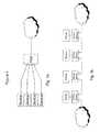
- FIG. 1describes Ethernet topologies
- FIG. 2is a schematic of the device server circuit board
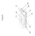
- FIG. 3is a perspective view of a device server
- FIG. 4shows an internal view of a device server
- FIG. 1compares two topologies.
- FIG. 1 ashows an Ethernet “star” topology
- FIG. 1 bshows a “daisy chain” topology wherein devices are connected in series, one after the other in linear fashion, by using two Ethernet ports on each daisy chained device.
- the device server circuit board 10interconnects the device server circuitry.
- the control microprocessor 11is DSTni-EX, a System-on-chip (SOC) integrated circuit.
- DSTni-EXincludes serial communications ports, on-board RAM and ROM, an Ethernet MAC and PHY, and ample address and data lines to connect and control lights and GPIO pins.
- a DC to DC converter 30capable of supplying a 3 Watt load is galvanically isolated from input to output by a breakdown rating of 2000 volts.
- a protection circuit 21prevents electrical overstress of the converter by absorbing and dissipating excess joules of energy.
- the protection circuitalso accepts AC and DC input and with diode steering provides DC to the input of the converter.
- the wide range of input allowed, 9 to 30 volts DC and 9 to 24 volts ACaccommodate varying external supplies with a single device server PCB 10 .
- Electrostatic Discharge (ESD) and Noise Filtering capacitance 27is provided on the power supply input lines.
- Power from the DC to DC converter outputis further filtered and provided to the DSTni-EX 11 as 3.3V, and the converter output also drives a 1.8V linear regulator 12 for core voltage to the DSTni-EX.
- Other components on the PCB powered from the 3.3V sourceinclude varying amounts of SRAM 13 and FLASH memory 14 , serial line drivers for RS232 28 and 422/485 protocols 29 , an Ethernet switch 17 , a small EEROM 18 , a reset IC 19 , pulse stretching circuitry and status and activity LEDs 15 .
- FIG. 3shows a perspective view of the device server within a housing 25 .
- Basic to a preferred embodiment of a daisy chained device serverare at least one of the serial ports 22 and at least two of the Ethernet ports 24 all shown exposed through the walls of the housing. It is apparent that there can be variations on the physical nature of the serial interface and the communications protocol implemented. For example, also shown is a RS4XX (an abbreviation for RS422 or RS485 standards) serial port 23 . Activity and status indicators 15 are shown visible from outside the housing.
- the housingcan further comprise mounting features 26 which facilitate attachment to supporting structures. Connection for power is not illustrated.
- FIG. 4shows an internal view of the device server, with housing 25 removed.
- the circuit board 10contains the Ethernet ports 24 , the serial ports 22 , activity and status indicators 15 , a processor 11 and a hardware Ethernet switch 17 .
- the device server functionis to translate information between serial ports and Ethernet ports. To do so, the DSTni-EX processor executes software instructions stored in the Flash memory. These software instructions are organized logically into a device server application, a web server, an operating system, and drivers for hardware elements. Additionally, other software, such as HTML and Java applets can be stored in Flash or RAM and can be transmitted over one of the Ethernet ports to a remote client by the web server module. It is possible for software stored in Flash to be modified, and custom versions of the device server application code are commonly developed for a specific need or purpose. A kit containing development software and selected source and object code for the device server application is available and can be used by trained programmers to create, load, execute and debug such custom device server applications.
- an inventive element of the device serveris the inclusion of an Ethernet switch function.
- the Ethernet switch functioncan be implemented either as hardware or software, or in a combination of both.
- packet handling functionssometimes abstracted into “hub”, “switch”, and “router” functions.
- hubthe number of packet handling functions
- switchthe number of packet handling functions
- routerthe number of packet handling functions
- all such packet handling functionswill be abstracted into the “switch” function herein, by which term we mean all ways of handling and routing packets as they arrive at any of the network ports of the device server.
- the switch functionis performed by an Integrated Circuit chip.
- a preferred embodimentcan use an integrated circuit such as Micrel KS8993M configured on the circuit board as shown in FIG. 3 .
- This integrated circuitoffers an extensive feature set that includes tag/port-based VLAN, QoS priority, switch management, MEB counters and interfaces to MII (Media Independent Interface) and CPU for design flexibility to address emerging Ethernet applications.
- the Integrated Circuit chipinterfaces to the DSTni-EX through the MII (Media Independent Interface) port on the DSTni-EX, and further drives two Ethernet ports.
- the device serveris capable of being installed in a “daisy-chained” manner with similar device servers or other compatible network equipment.
- the switch functioncan implement a standard and well-documented Ethernet packet switching function described in IEEE 802.1d Spanning Tree Protocol. Because the switch function builds and maintains tables of MAC addresses observed on each device server Ethernet port the switch function is able to determine which Ethernet port to employ when passing on packets not intended for the present device server. Thus normal network communications not intended for the current device server are handled appropriately and transparently both up and down the daisy chain connection.
- software running in the DSTni-EXcan alternatively perform some or all of the switch function, reducing the requirements on, or eliminating, a hardware switch element.
- Additional Ethernet portscan be incorporated in the device server, and additional switch functions can be implemented with two or more ports as desired.
- a preferred embodimentis compliant with relevant Ethernet standards as defined for general network equipment.
- Wireless Ethernetcan be substituted for any or all wired Ethernet ports, in any existing wireless standard. Also contemplated are all future wireless network standards.
- a housing for the circuitrycan be provided, and it can have provision for geometric features to facilitate attachment to a support structure.
- Such attaching featurescan include mounting ears for fasteners, tabs, brackets, clips and other facilitating shapes and surfaces. Also contemplated are magnetic and chemical attachment mechanisms. Attaching features can be designed to existing or future standards, such as the provision of integral DIN rail attachment features.
- Receive and Transmit indicator lampsare visible from outside the housing, and the indicator lamps are driven with a pulse stretching circuit so that rapid signal transitions to and from a given state will be extended in duration to be visible.
- power for operationcan be supplied to the device server via Power over Ethernet (POE), as described in IEEE Std 802.3afTM-2003.
- POEPower over Ethernet
- MDIEthernet Media Dependent Interface
- device serverscan supply other interface standards and protocols, such as USB and Firewire.
- Analog signalscan be supported for certain specific or general applications, such as Analog to Digital converter input, voltage and current monitoring or other sensing and control applications.
- the device servercan implement more I/O capability in the form of General Programmable I/O (GPIO) pins—pins that can be defined as input, output or bidirectional digital pins, or which can be assigned a definition of fixed or varying nature, as supported by internal device server software.
- GPIOGeneral Programmable I/O
- an inventive elementprovides a device server or Serial to Ethernet Converter with a plurality of serial ports wherein at least two ports are logically connected in that information arriving at a first port is passed internally through the device server to a second port, and information arriving at the second port is passed internally through the device server to the first port.
Landscapes
- Engineering & Computer Science (AREA)
- Computer Networks & Wireless Communication (AREA)
- Signal Processing (AREA)
- Small-Scale Networks (AREA)
- Power Sources (AREA)
Abstract
Description
Claims (19)
Priority Applications (6)
| Application Number | Priority Date | Filing Date | Title |
|---|---|---|---|
| US11/273,791US8428054B2 (en) | 2005-11-14 | 2005-11-14 | Daisy chaining device servers via ethernet |
| JP2008540263AJP2009516432A (en) | 2005-11-14 | 2006-11-13 | Device server for daisy chain connection via Ethernet (registered trademark) |
| PCT/US2006/044061WO2007059067A2 (en) | 2005-11-14 | 2006-11-13 | Daisy chaining device servers via ethernet |
| EP06837480AEP1949506A4 (en) | 2005-11-14 | 2006-11-13 | Daisy chaining device servers via ethernet |
| CA2626729ACA2626729C (en) | 2005-11-14 | 2006-11-13 | Daisy chaining device servers via ethernet |
| US13/867,453US20130301495A1 (en) | 2005-11-14 | 2013-04-22 | Daisy Chaining Device Servers Via Ethernet |
Applications Claiming Priority (1)
| Application Number | Priority Date | Filing Date | Title |
|---|---|---|---|
| US11/273,791US8428054B2 (en) | 2005-11-14 | 2005-11-14 | Daisy chaining device servers via ethernet |
Related Child Applications (1)
| Application Number | Title | Priority Date | Filing Date |
|---|---|---|---|
| US13/867,453ContinuationUS20130301495A1 (en) | 2005-11-14 | 2013-04-22 | Daisy Chaining Device Servers Via Ethernet |
Publications (2)
| Publication Number | Publication Date |
|---|---|
| US20070110081A1 US20070110081A1 (en) | 2007-05-17 |
| US8428054B2true US8428054B2 (en) | 2013-04-23 |
Family
ID=38040750
Family Applications (2)
| Application Number | Title | Priority Date | Filing Date |
|---|---|---|---|
| US11/273,791Active2027-12-16US8428054B2 (en) | 2005-11-14 | 2005-11-14 | Daisy chaining device servers via ethernet |
| US13/867,453AbandonedUS20130301495A1 (en) | 2005-11-14 | 2013-04-22 | Daisy Chaining Device Servers Via Ethernet |
Family Applications After (1)
| Application Number | Title | Priority Date | Filing Date |
|---|---|---|---|
| US13/867,453AbandonedUS20130301495A1 (en) | 2005-11-14 | 2013-04-22 | Daisy Chaining Device Servers Via Ethernet |
Country Status (5)
| Country | Link |
|---|---|
| US (2) | US8428054B2 (en) |
| EP (1) | EP1949506A4 (en) |
| JP (1) | JP2009516432A (en) |
| CA (1) | CA2626729C (en) |
| WO (1) | WO2007059067A2 (en) |
Cited By (6)
| Publication number | Priority date | Publication date | Assignee | Title |
|---|---|---|---|---|
| US20130286896A1 (en)* | 2012-04-27 | 2013-10-31 | Selph Secured LLC | Telecommunications and computer network interconnectivity apparatuses and methods thereof |
| US20180314219A1 (en)* | 2017-04-28 | 2018-11-01 | Johnson Controls Technology Company | Building devices with communication subsystems independently powered by power over ethernet (poe) |
| US11474592B2 (en) | 2019-09-17 | 2022-10-18 | Honeywell International Inc. | Daisy-chained power-over-ethernet (PoE) network |
| US11546187B2 (en) | 2018-12-17 | 2023-01-03 | Graco Minnesota Inc. | Large packet daisy chain serial bus |
| US11704257B1 (en) | 2022-04-15 | 2023-07-18 | Graco Minnesota Inc. | System provisioning using virtual peripherals |
| US12229058B2 (en) | 2018-12-17 | 2025-02-18 | Graco Minnesota Inc. | Large packet daisy chain serial bus |
Families Citing this family (21)
| Publication number | Priority date | Publication date | Assignee | Title |
|---|---|---|---|---|
| US7930043B2 (en) | 2006-09-15 | 2011-04-19 | International Business Machines Corporation | Method and system for discovery, validation and delivery of power through a universal power center |
| US8004863B2 (en)* | 2007-12-26 | 2011-08-23 | Silicon Laboratories Inc. | Circuit device and method of providing feedback across an isolation barrier |
| EP2359237A4 (en)* | 2008-11-28 | 2012-04-25 | Siemens Ag | AUTOMATIC CONTROL SYSTEM AND METHOD FOR EXECUTING A PARALLEL CONTROL PROGRAM |
| US9244866B2 (en) | 2010-04-30 | 2016-01-26 | International Business Machines Corporation | Remote access of peripheral device connected to serial bus |
| US8954762B2 (en)* | 2010-06-08 | 2015-02-10 | International Business Machines Corporation | Peer to peer power management |
| US9397960B2 (en) | 2011-11-08 | 2016-07-19 | Mellanox Technologies Ltd. | Packet steering |
| US10454991B2 (en)* | 2014-03-24 | 2019-10-22 | Mellanox Technologies, Ltd. | NIC with switching functionality between network ports |
| US10200203B2 (en) | 2014-07-16 | 2019-02-05 | Honeywell International Inc. | Controllers with integrated power over ethernet network switches |
| US20160156569A1 (en)* | 2014-11-28 | 2016-06-02 | Igor, Inc. | Node and Method of Assigning Node to Space |
| CA2891165A1 (en) | 2015-05-14 | 2016-11-14 | Peter E. Freill | Lighting assembly, system and installation method for hardscapes and steps |
| CN106898131A (en)* | 2015-12-17 | 2017-06-27 | 广州航天海特系统工程有限公司 | A kind of single fiber data transmission system |
| CN106200829A (en)* | 2016-08-31 | 2016-12-07 | 安徽康海时代科技股份有限公司 | RJ45 type double-serial port server |
| JP6988650B2 (en)* | 2018-03-30 | 2022-01-05 | オムロン株式会社 | Control device |
| US11388809B2 (en) | 2019-03-25 | 2022-07-12 | Recarbon, Inc. | Systems for controlling plasma reactors |
| BE1027224B1 (en) | 2019-04-24 | 2020-11-23 | Phoenix Contact Gmbh & Co | Modular switch for use in a data transmission and control system |
| US11397419B2 (en)* | 2019-09-24 | 2022-07-26 | Rockwell Automation Technologies, Inc. | Electrical status indication system |
| DE102019127195A1 (en) | 2019-10-09 | 2021-04-15 | Phoenix Contact Gmbh & Co. Kg | Modular interface system for connecting a control device and field devices |
| DE102019127551A1 (en)* | 2019-10-14 | 2021-04-15 | Phoenix Contact Gmbh & Co. Kg | Multifunctional switch for use in a process-controlling automation system as well as such a process-controlling automation system |
| DE102021106522A1 (en) | 2020-03-27 | 2021-09-30 | Phoenix Contact Gmbh & Co. Kg | Backplane module for the electrical connection of several function modules and a modular communication system |
| US11748261B2 (en)* | 2020-07-24 | 2023-09-05 | Eaton Intelligent Power Limited | Automatic address generation for modular electronic devices |
| US11398979B2 (en) | 2020-10-28 | 2022-07-26 | Mellanox Technologies, Ltd. | Dynamic processing trees |
Citations (22)
| Publication number | Priority date | Publication date | Assignee | Title |
|---|---|---|---|---|
| US4890102A (en)* | 1987-05-26 | 1989-12-26 | Cabletron, Inc. | Visual display for communication network monitoring and troubleshooting |
| US5555100A (en)* | 1993-10-07 | 1996-09-10 | Audiofax, Inc. | Facsimile store and forward system with local interface translating DTMF signals into store and forward system commands |
| US5598418A (en)* | 1994-11-10 | 1997-01-28 | Advanced Micro Devices Inc. | Repeater status LED array interface |
| US6139177A (en) | 1996-12-03 | 2000-10-31 | Hewlett Packard Company | Device access and control using embedded web access functionality |
| US6259978B1 (en)* | 1996-12-06 | 2001-07-10 | Union Switch & Signal, Inc. | Programmable relay driver |
| US6373841B1 (en) | 1998-06-22 | 2002-04-16 | Agilent Technologies, Inc. | Integrated LAN controller and web server chip |
| US20030099076A1 (en)* | 1999-08-02 | 2003-05-29 | Shimon Elkayam | Integral board and module for power over LAN |
| US20030142683A1 (en)* | 2002-01-25 | 2003-07-31 | Barry Lam | Method and apparatus for a flexible peripheral access router |
| WO2004038900A2 (en) | 2002-10-21 | 2004-05-06 | Advanced Power Technology, Inc. | Ac-dc power converter having high input power factor and low harmonic distortion |
| US6735635B1 (en)* | 2000-05-18 | 2004-05-11 | International Business Machines Corporation | Dynamic preamble configuration on a shared bus |
| US20040162912A1 (en)* | 2002-10-04 | 2004-08-19 | Taraci Brian Richard | Method and apparatus for providing universal web access functionality |
| US6793539B1 (en)* | 2003-04-18 | 2004-09-21 | Accton Technology Corporation | Linking apparatus for stackable network devices |
| US20050044431A1 (en)* | 2003-05-23 | 2005-02-24 | Lang Jonathan P. | System and method for operating a sensed power device over data wiring |
| US20050129033A1 (en) | 2003-12-13 | 2005-06-16 | Gordy Stephen C. | Network tap for use with multiple attached devices |
| US20050245127A1 (en)* | 2004-05-03 | 2005-11-03 | Nordin Ronald A | Powered patch panel |
| US20060116023A1 (en)* | 2004-09-20 | 2006-06-01 | Spitaels James S | Equipment rack data/power distribution |
| US20060198389A1 (en)* | 2005-03-01 | 2006-09-07 | Eriokson Michael J | Multi-drop ethernet |
| US20060285802A1 (en)* | 2003-02-12 | 2006-12-21 | Larry Fingler | Fiber-optic premises wiring system |
| US20070025240A1 (en)* | 2005-07-29 | 2007-02-01 | Snide Todd A | Bypass switch for an ethernet device and method of bypassing devices in an ethernet network |
| US7376760B1 (en)* | 2003-02-28 | 2008-05-20 | United Electronic Industries | Methods and apparatus to support acquisition of data |
| US7433302B2 (en)* | 2005-05-04 | 2008-10-07 | Micrel, Inc. | Ethernet network implementing redundancy using a single category 5 cable |
| US7447762B2 (en)* | 2001-04-02 | 2008-11-04 | Curray Timothy G | Ethernet communications for power monitoring system |
Family Cites Families (18)
| Publication number | Priority date | Publication date | Assignee | Title |
|---|---|---|---|---|
| JPH05227187A (en)* | 1992-02-14 | 1993-09-03 | Matsushita Electric Works Ltd | Cascade connection system for twist pair line lan |
| JP3261162B2 (en)* | 1992-06-25 | 2002-02-25 | 松下電工株式会社 | Remote monitoring and control system |
| JPH09504680A (en)* | 1994-08-24 | 1997-05-06 | フィリップス エレクトロニクス ネムローゼ フェンノートシャップ | Device including transient voltage suppression means |
| US5994998A (en)* | 1997-05-29 | 1999-11-30 | 3Com Corporation | Power transfer apparatus for concurrently transmitting data and power over data wires |
| JP2000132201A (en)* | 1998-10-27 | 2000-05-12 | Hitachi Ltd | Distributed control system using heterogeneous communication media |
| JP2000284853A (en)* | 1999-03-30 | 2000-10-13 | Sumitomo Wiring Syst Ltd | Portable network computing device and its using method |
| JP2002077191A (en)* | 2000-08-31 | 2002-03-15 | Matsushita Electric Works Ltd | Communication network coping type power feeding connector |
| JP2002287242A (en)* | 2001-01-19 | 2002-10-03 | Mitsubishi Electric Corp | Projector, network system, and centralized management method for projector |
| US6977939B2 (en)* | 2001-01-26 | 2005-12-20 | Microsoft Corporation | Method and apparatus for emulating ethernet functionality over a serial bus |
| JP2002244606A (en)* | 2001-02-14 | 2002-08-30 | Sony Corp | Device and method for advertisement display |
| JP2003018173A (en)* | 2001-07-05 | 2003-01-17 | Nippon Telegr & Teleph Corp <Ntt> | Home network wiring unit using UTP power supply |
| US6881096B2 (en)* | 2002-04-15 | 2005-04-19 | Lantronix, Inc. | Compact serial-to-ethernet conversion port |
| JP2004112120A (en)* | 2002-09-13 | 2004-04-08 | Aruze Corp | Portable relay hub |
| US20040255018A1 (en)* | 2002-10-04 | 2004-12-16 | Brian Taraci | Method and apparatus for providing universal web access functionality with port contention resolution |
| JP2004214956A (en)* | 2002-12-27 | 2004-07-29 | Synclayer Inc | Radio lan system using optical fiber and its radio lan repeater |
| JP4213621B2 (en)* | 2003-06-26 | 2009-01-21 | 株式会社東芝 | Railway vehicle transmission equipment |
| US7692773B2 (en)* | 2003-08-05 | 2010-04-06 | Luminex Corporation | Light emitting diode based measurement systems |
| JP2005070975A (en)* | 2003-08-21 | 2005-03-17 | Sharp Corp | Repeater system and control system |
- 2005
- 2005-11-14USUS11/273,791patent/US8428054B2/enactiveActive
- 2006
- 2006-11-13EPEP06837480Apatent/EP1949506A4/ennot_activeWithdrawn
- 2006-11-13JPJP2008540263Apatent/JP2009516432A/enactivePending
- 2006-11-13CACA2626729Apatent/CA2626729C/enactiveActive
- 2006-11-13WOPCT/US2006/044061patent/WO2007059067A2/enactiveApplication Filing
- 2013
- 2013-04-22USUS13/867,453patent/US20130301495A1/ennot_activeAbandoned
Patent Citations (23)
| Publication number | Priority date | Publication date | Assignee | Title |
|---|---|---|---|---|
| US4890102A (en)* | 1987-05-26 | 1989-12-26 | Cabletron, Inc. | Visual display for communication network monitoring and troubleshooting |
| US5555100A (en)* | 1993-10-07 | 1996-09-10 | Audiofax, Inc. | Facsimile store and forward system with local interface translating DTMF signals into store and forward system commands |
| US6157464A (en)* | 1993-10-07 | 2000-12-05 | Ptek Holdings, Inc. | Facsimile store and forward system with local interface |
| US5598418A (en)* | 1994-11-10 | 1997-01-28 | Advanced Micro Devices Inc. | Repeater status LED array interface |
| US6139177A (en) | 1996-12-03 | 2000-10-31 | Hewlett Packard Company | Device access and control using embedded web access functionality |
| US6259978B1 (en)* | 1996-12-06 | 2001-07-10 | Union Switch & Signal, Inc. | Programmable relay driver |
| US6373841B1 (en) | 1998-06-22 | 2002-04-16 | Agilent Technologies, Inc. | Integrated LAN controller and web server chip |
| US20030099076A1 (en)* | 1999-08-02 | 2003-05-29 | Shimon Elkayam | Integral board and module for power over LAN |
| US6735635B1 (en)* | 2000-05-18 | 2004-05-11 | International Business Machines Corporation | Dynamic preamble configuration on a shared bus |
| US7447762B2 (en)* | 2001-04-02 | 2008-11-04 | Curray Timothy G | Ethernet communications for power monitoring system |
| US20030142683A1 (en)* | 2002-01-25 | 2003-07-31 | Barry Lam | Method and apparatus for a flexible peripheral access router |
| US20040162912A1 (en)* | 2002-10-04 | 2004-08-19 | Taraci Brian Richard | Method and apparatus for providing universal web access functionality |
| WO2004038900A2 (en) | 2002-10-21 | 2004-05-06 | Advanced Power Technology, Inc. | Ac-dc power converter having high input power factor and low harmonic distortion |
| US20060285802A1 (en)* | 2003-02-12 | 2006-12-21 | Larry Fingler | Fiber-optic premises wiring system |
| US7376760B1 (en)* | 2003-02-28 | 2008-05-20 | United Electronic Industries | Methods and apparatus to support acquisition of data |
| US6793539B1 (en)* | 2003-04-18 | 2004-09-21 | Accton Technology Corporation | Linking apparatus for stackable network devices |
| US20050044431A1 (en)* | 2003-05-23 | 2005-02-24 | Lang Jonathan P. | System and method for operating a sensed power device over data wiring |
| US20050129033A1 (en) | 2003-12-13 | 2005-06-16 | Gordy Stephen C. | Network tap for use with multiple attached devices |
| US20050245127A1 (en)* | 2004-05-03 | 2005-11-03 | Nordin Ronald A | Powered patch panel |
| US20060116023A1 (en)* | 2004-09-20 | 2006-06-01 | Spitaels James S | Equipment rack data/power distribution |
| US20060198389A1 (en)* | 2005-03-01 | 2006-09-07 | Eriokson Michael J | Multi-drop ethernet |
| US7433302B2 (en)* | 2005-05-04 | 2008-10-07 | Micrel, Inc. | Ethernet network implementing redundancy using a single category 5 cable |
| US20070025240A1 (en)* | 2005-07-29 | 2007-02-01 | Snide Todd A | Bypass switch for an ethernet device and method of bypassing devices in an ethernet network |
Cited By (7)
| Publication number | Priority date | Publication date | Assignee | Title |
|---|---|---|---|---|
| US20130286896A1 (en)* | 2012-04-27 | 2013-10-31 | Selph Secured LLC | Telecommunications and computer network interconnectivity apparatuses and methods thereof |
| US20180314219A1 (en)* | 2017-04-28 | 2018-11-01 | Johnson Controls Technology Company | Building devices with communication subsystems independently powered by power over ethernet (poe) |
| US10908570B2 (en)* | 2017-04-28 | 2021-02-02 | Johnson Controls Technology Company | Building devices with communication subsystems independently powered by power over Ethernet (POE) |
| US11546187B2 (en) | 2018-12-17 | 2023-01-03 | Graco Minnesota Inc. | Large packet daisy chain serial bus |
| US12229058B2 (en) | 2018-12-17 | 2025-02-18 | Graco Minnesota Inc. | Large packet daisy chain serial bus |
| US11474592B2 (en) | 2019-09-17 | 2022-10-18 | Honeywell International Inc. | Daisy-chained power-over-ethernet (PoE) network |
| US11704257B1 (en) | 2022-04-15 | 2023-07-18 | Graco Minnesota Inc. | System provisioning using virtual peripherals |
Also Published As
| Publication number | Publication date |
|---|---|
| CA2626729A1 (en) | 2007-05-24 |
| US20130301495A1 (en) | 2013-11-14 |
| US20070110081A1 (en) | 2007-05-17 |
| WO2007059067A2 (en) | 2007-05-24 |
| WO2007059067A3 (en) | 2007-12-13 |
| EP1949506A2 (en) | 2008-07-30 |
| JP2009516432A (en) | 2009-04-16 |
| EP1949506A4 (en) | 2011-04-20 |
| CA2626729C (en) | 2012-05-29 |
Similar Documents
| Publication | Publication Date | Title |
|---|---|---|
| CA2626729C (en) | Daisy chaining device servers via ethernet | |
| US20150106447A1 (en) | Modular system and method for communicating information between different protocols on a control network | |
| EP2624375B1 (en) | Power distribution system | |
| US20080062003A1 (en) | Wireless controllable power control device molded into a power cable | |
| EP1943842A1 (en) | A patch panel with power over ethernet functionality | |
| US11128741B2 (en) | Auto-negotiation over extended backplane | |
| WO2006126160A2 (en) | Power and data transmission over ethernet network | |
| CN201230321Y (en) | Serial port communication adaptor | |
| US9134774B2 (en) | Sharing power between network devices | |
| CN110059513A (en) | A kind of RFID reader system based on PROFINET network | |
| CN211293729U (en) | Remote control multifunctional PLC experimental box | |
| CN214507096U (en) | Ethernet power supply architecture | |
| Cisco | Catalyst 1600 FDDI Module Installation and Configuration Notes | |
| CN221575411U (en) | Multi-protocol conversion gateway equipment based on industrial field bus | |
| CN218473171U (en) | Three-in-one gateway device | |
| CN219496943U (en) | Multi-protocol and extensible integrated remote IO module | |
| Praus | A versatile networked embedded platform for KNX/EIB | |
| CN215269094U (en) | High-speed long-range IO signal acquisition device of industry five unification agreements | |
| CN220208258U (en) | Circuit for realizing conversion from network port to serial port | |
| CN212909557U (en) | Ethernet-to-serial terminal with multi-mode power supply | |
| US11736315B2 (en) | Flexible power and data infrastructure | |
| CN215954081U (en) | An adaptive AIDI expansion board based on CAN bus | |
| CN221595644U (en) | USB serial port multipath level conversion device | |
| CN108717160B (en) | Embedded circuit system monitoring equipment | |
| CN118264725A (en) | IP adapter of HART instrument and network system thereof |
Legal Events
| Date | Code | Title | Description |
|---|---|---|---|
| AS | Assignment | Owner name:LANTRONIX, INC.,CALIFORNIA Free format text:ASSIGNMENT OF ASSIGNORS INTEREST;ASSIGNOR:MILLER, DARYL R.;REEL/FRAME:017244/0256 Effective date:20051114 Owner name:LANTRONIX, INC., CALIFORNIA Free format text:ASSIGNMENT OF ASSIGNORS INTEREST;ASSIGNOR:MILLER, DARYL R.;REEL/FRAME:017244/0256 Effective date:20051114 | |
| AS | Assignment | Owner name:SILICON VALLEY BANK, CALIFORNIA Free format text:ADDENDUM TO INTELLECTUAL PROPERTY SECURITY AGREEMENT;ASSIGNOR:LANTRONIX, INC.;REEL/FRAME:021478/0516 Effective date:20080829 Owner name:SILICON VALLEY BANK,CALIFORNIA Free format text:ADDENDUM TO INTELLECTUAL PROPERTY SECURITY AGREEMENT;ASSIGNOR:LANTRONIX, INC.;REEL/FRAME:021478/0516 Effective date:20080829 | |
| STCF | Information on status: patent grant | Free format text:PATENTED CASE | |
| FPAY | Fee payment | Year of fee payment:4 | |
| MAFP | Maintenance fee payment | Free format text:PAYMENT OF MAINTENANCE FEE, 8TH YR, SMALL ENTITY (ORIGINAL EVENT CODE: M2552); ENTITY STATUS OF PATENT OWNER: SMALL ENTITY Year of fee payment:8 | |
| MAFP | Maintenance fee payment | Free format text:PAYMENT OF MAINTENANCE FEE, 12TH YR, SMALL ENTITY (ORIGINAL EVENT CODE: M2553); ENTITY STATUS OF PATENT OWNER: SMALL ENTITY Year of fee payment:12 | |
| AS | Assignment | Owner name:TRANSITION NEWTORKS, INC., CALIFORNIA Free format text:RELEASE BY SECURED PARTY;ASSIGNOR:SVB INNOVATION CREDIT FUND VIII, L.P.;REEL/FRAME:071290/0001 Effective date:20220120 Owner name:LANTRONIX CANADA, ULC, CALIFORNIA Free format text:RELEASE BY SECURED PARTY;ASSIGNOR:SVB INNOVATION CREDIT FUND VIII, L.P.;REEL/FRAME:071290/0001 Effective date:20220120 Owner name:LANTRONIX TECHNOLOGIES CANADA (TAIWAN) LTD., CALIFORNIA Free format text:RELEASE BY SECURED PARTY;ASSIGNOR:SVB INNOVATION CREDIT FUND VIII, L.P.;REEL/FRAME:071290/0001 Effective date:20220120 Owner name:LANTRONIX HOLDING COMPANY, CALIFORNIA Free format text:RELEASE BY SECURED PARTY;ASSIGNOR:SVB INNOVATION CREDIT FUND VIII, L.P.;REEL/FRAME:071290/0001 Effective date:20220120 Owner name:LANTRONIX, INC., CALIFORNIA Free format text:RELEASE BY SECURED PARTY;ASSIGNOR:SVB INNOVATION CREDIT FUND VIII, L.P.;REEL/FRAME:071290/0001 Effective date:20220120 Owner name:SILICON VALLEY BANK, CALIFORNIA Free format text:SECURITY INTEREST;ASSIGNORS:LANTRONIX, INC.;LANTRONIX HOLDING COMPANY;LANTRONIX TECHNOLOGIES CANADA (TAIWAN) LTD.;AND OTHERS;REEL/FRAME:071290/0044 Effective date:20221012 |