US8427552B2 - Extending the operational lifetime of a hard-disk drive used in video data storage applications - Google Patents
Extending the operational lifetime of a hard-disk drive used in video data storage applicationsDownload PDFInfo
- Publication number
- US8427552B2 US8427552B2US12/105,893US10589308AUS8427552B2US 8427552 B2US8427552 B2US 8427552B2US 10589308 AUS10589308 AUS 10589308AUS 8427552 B2US8427552 B2US 8427552B2
- Authority
- US
- United States
- Prior art keywords
- video
- hard
- disk drive
- data
- storage
- Prior art date
- Legal status (The legal status is an assumption and is not a legal conclusion. Google has not performed a legal analysis and makes no representation as to the accuracy of the status listed.)
- Expired - Fee Related, expires
Links
Images


Classifications
- G—PHYSICS
- G06—COMPUTING OR CALCULATING; COUNTING
- G06T—IMAGE DATA PROCESSING OR GENERATION, IN GENERAL
- G06T7/00—Image analysis
- G—PHYSICS
- G06—COMPUTING OR CALCULATING; COUNTING
- G06F—ELECTRIC DIGITAL DATA PROCESSING
- G06F1/00—Details not covered by groups G06F3/00 - G06F13/00 and G06F21/00
- G06F1/26—Power supply means, e.g. regulation thereof
- G06F1/32—Means for saving power
- G06F1/3203—Power management, i.e. event-based initiation of a power-saving mode
- G06F1/3234—Power saving characterised by the action undertaken
- G06F1/3246—Power saving characterised by the action undertaken by software initiated power-off
- G—PHYSICS
- G06—COMPUTING OR CALCULATING; COUNTING
- G06F—ELECTRIC DIGITAL DATA PROCESSING
- G06F3/00—Input arrangements for transferring data to be processed into a form capable of being handled by the computer; Output arrangements for transferring data from processing unit to output unit, e.g. interface arrangements
- G06F3/06—Digital input from, or digital output to, record carriers, e.g. RAID, emulated record carriers or networked record carriers
- G06F3/0601—Interfaces specially adapted for storage systems
- G06F3/0602—Interfaces specially adapted for storage systems specifically adapted to achieve a particular effect
- G06F3/0614—Improving the reliability of storage systems
- G06F3/0616—Improving the reliability of storage systems in relation to life time, e.g. increasing Mean Time Between Failures [MTBF]
- G—PHYSICS
- G11—INFORMATION STORAGE
- G11B—INFORMATION STORAGE BASED ON RELATIVE MOVEMENT BETWEEN RECORD CARRIER AND TRANSDUCER
- G11B20/00—Signal processing not specific to the method of recording or reproducing; Circuits therefor
- G11B20/10—Digital recording or reproducing
- G11B20/10527—Audio or video recording; Data buffering arrangements
- H—ELECTRICITY
- H04—ELECTRIC COMMUNICATION TECHNIQUE
- H04N—PICTORIAL COMMUNICATION, e.g. TELEVISION
- H04N23/00—Cameras or camera modules comprising electronic image sensors; Control thereof
- H—ELECTRICITY
- H04—ELECTRIC COMMUNICATION TECHNIQUE
- H04N—PICTORIAL COMMUNICATION, e.g. TELEVISION
- H04N23/00—Cameras or camera modules comprising electronic image sensors; Control thereof
- H04N23/60—Control of cameras or camera modules
- H04N23/65—Control of camera operation in relation to power supply
- H—ELECTRICITY
- H04—ELECTRIC COMMUNICATION TECHNIQUE
- H04N—PICTORIAL COMMUNICATION, e.g. TELEVISION
- H04N5/00—Details of television systems
- H04N5/76—Television signal recording
- H04N5/765—Interface circuits between an apparatus for recording and another apparatus
- H04N5/77—Interface circuits between an apparatus for recording and another apparatus between a recording apparatus and a television camera
- H04N5/772—Interface circuits between an apparatus for recording and another apparatus between a recording apparatus and a television camera the recording apparatus and the television camera being placed in the same enclosure
- H—ELECTRICITY
- H04—ELECTRIC COMMUNICATION TECHNIQUE
- H04N—PICTORIAL COMMUNICATION, e.g. TELEVISION
- H04N7/00—Television systems
- H04N7/18—Closed-circuit television [CCTV] systems, i.e. systems in which the video signal is not broadcast
- H—ELECTRICITY
- H04—ELECTRIC COMMUNICATION TECHNIQUE
- H04N—PICTORIAL COMMUNICATION, e.g. TELEVISION
- H04N7/00—Television systems
- H04N7/18—Closed-circuit television [CCTV] systems, i.e. systems in which the video signal is not broadcast
- H04N7/181—Closed-circuit television [CCTV] systems, i.e. systems in which the video signal is not broadcast for receiving images from a plurality of remote sources
- H—ELECTRICITY
- H04—ELECTRIC COMMUNICATION TECHNIQUE
- H04N—PICTORIAL COMMUNICATION, e.g. TELEVISION
- H04N9/00—Details of colour television systems
- H04N9/79—Processing of colour television signals in connection with recording
- H04N9/7921—Processing of colour television signals in connection with recording for more than one processing mode
- H—ELECTRICITY
- H04—ELECTRIC COMMUNICATION TECHNIQUE
- H04N—PICTORIAL COMMUNICATION, e.g. TELEVISION
- H04N9/00—Details of colour television systems
- H04N9/79—Processing of colour television signals in connection with recording
- H04N9/80—Transformation of the television signal for recording, e.g. modulation, frequency changing; Inverse transformation for playback
- H04N9/82—Transformation of the television signal for recording, e.g. modulation, frequency changing; Inverse transformation for playback the individual colour picture signal components being recorded simultaneously only
- H04N9/8205—Transformation of the television signal for recording, e.g. modulation, frequency changing; Inverse transformation for playback the individual colour picture signal components being recorded simultaneously only involving the multiplexing of an additional signal and the colour video signal
- H—ELECTRICITY
- H04—ELECTRIC COMMUNICATION TECHNIQUE
- H04N—PICTORIAL COMMUNICATION, e.g. TELEVISION
- H04N23/00—Cameras or camera modules comprising electronic image sensors; Control thereof
- H04N23/60—Control of cameras or camera modules
- H04N23/66—Remote control of cameras or camera parts, e.g. by remote control devices
Definitions
- This disclosuredescribes a video imaging system that intelligently recognizes the content of video data, reduces system storage capacity demands, and prolongs the operational lifespan of video data mass storage units.
- Network camera systemsfor example network surveillance camera systems or IP camera systems, have existed for a number of years but have undergone relatively slow industry adoption. Compared to traditional analog camera systems, network camera systems offer advantages such as accessibility, integration, low installation costs, scalability, and an ability to move to higher resolution video. Data produced by network cameras, however, demand large amounts of bandwidth and storage capacity.
- Bandwidth problems associated with network camera systemshave lead to more complex camera networks that include an increased number of switches and, in some cases, complete alternative data paths.
- Storage problems associated with network camera systemsbecome magnified as video resolution and the number of cameras in a system increase.
- a single standard D1 resolution camera using MPEG-4 compression and operating at 30 frames-per-second (fps)can require 360 gigabytes (GB) of storage for video data representing one month of video data.
- GBgigabytes
- a camera system with 1000 camerastherefore, would require 360 terabytes (TB) of storage for data spanning one month.
- This exampledemonstrates a huge cost and facility management challenge presented with network camera systems, especially where mega-pixel resolution is desired and where applications require six months or a year of video data storage.
- Typical storage architecture of network camera systemsis configured similarly to traditional analog systems.
- the architectureincludes centrally located digital video recorders (DVRs) or network video recorders (NVRs) connected through a network to IP cameras.
- DVRsdigital video recorders
- NVRsnetwork video recorders
- the typical architectureis inadequate for a number of reasons. For example, most DVRs and NVRs do not include open platforms such that a system is limited to one brand for future replacements and upgrades. Also, most DVRs and NVRs do not meet IT standards for system resiliency, redundancy, and long-term archiving of video data. Additionally, typical network camera systems often lack storage scalability such that, as network camera systems expand, storage systems require “forklift” upgrades.
- Video analyticshas been primarily used to alert security of potential unwanted events.
- Most video analyticsis performed by a central processor that is common to multiple cameras, but some video cameras have built-in video analytics capabilities. These video cameras with built-in analytics, however, have not included large capacity storage due to the large storage requirements of the video data generated by the camera. Also, there are some cameras configured without built-in video analytics but with built-in small storage capacity that is insufficient to serve as a substitute for traditional DVRs and NVRs.
- a solid state memoryfunctions as a storage buffer for video data produced by a video camera.
- the video datarepresent a scene under observation by the video camera.
- a hard-disk drive memoryoperates normally in a powered-down state.
- the video dataare stored in the storage buffer during a first time interval as the video data are produced by the video camera.
- the hard-disk driveis operated in a powered-up state.
- a portion of the video data stored in the storage bufferis transferred to and stored in the hard-disk drive memory in the powered-up state during a second time interval that is substantially shorter than the first time interval.
- the hard-disk drive memoryis returned to the powered-down state after completion of the transfer of video data, and for a total hard-disk drive storage time representing a sum of the second time intervals and a total buffer storage time representing a sum of the first time intervals over an operational lifetime of the hard-disk drive memory, the total hard-disk drive storage time spent transferring to and storing a portion of the video data in the hard-disk drive memory is substantially less than the total buffer storage time spent storing the video data in the storage buffer.
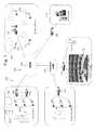
- FIG. 1depicts an embodiment of a network camera system.
- FIG. 2is a high level block diagram of a network camera of FIG. 1 .
- FIG. 3is a block diagram depicting the imaging system, video processing system, and data storage system of FIG. 2 according to a first embodiment.
- FIG. 4is a block diagram depicting an access control management unit operating in the video processing system of the first embodiment of FIG. 3 .
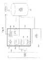
- FIG. 5is a block diagram depicting a second embodiment of the imaging system, video processing system, and data storage system of FIG. 2 .
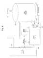
- FIG. 6is a block diagram depicting portions of the video processing system of the second embodiment.
- FIG. 7is a block diagram representing a memory buffer unit and a hard drive storage unit of data storage system.
- FIG. 8is an image of a bird perched on a birdfeeder, in which image the bird and birdfeeder are displayed as high quality images and a background scene is displayed in low quality.
- FIG. 1is a pictorial diagram depicting an embodiment of a network camera system 100 utilized in an application with local campus buildings and remote sites.
- Network camera system 100is not limited to video surveillance or to the application depicted, but may be used in any network communication system.
- Network camera system 100includes network cameras 102 connected to a central monitoring station 104 through a network 106 that includes a wide area network (WAN) 108 and a campus local area network (LAN) 110 .
- Network 106may also include a wireless network 112 that includes network cameras 102 ′ with wireless communication capabilities.
- Network 106establishes multiple network communications paths. The following descriptions of network camera 102 apply also to network camera 102 ′.
- Network 106is not limited to the configuration depicted, but may include various configurations and types of networks.
- a remote user 114may also be connected to network cameras 102 through WAN 108 .
- Network cameras 102may be connected to a remote storage unit 116 (i.e., a network data store).
- Network camera system 100may also include various switches 118 and routers 120 to facilitate communication over network 106 .
- network cameras 102capture various fields of view and generate data representing the fields of view. Certain applications may require substantially continuous operation of network camera 102 .
- the dataare communicated to central monitoring station 104 , in which a user may view images, generated from the data, depicting the fields of view. Also, the data may be communicated to remote user 114 to generate images of the fields of view.
- the datamay be stored in remote storage unit 116 and later accessed by a user.
- Network camera 102includes an imaging system 202 , a video processing system 204 , a data storage system 206 (i.e., a local data store), a power system 208 , and an input/output interface and control system 210 .
- Network camera 102includes a camera housing; and all or portions of systems 202 , 204 , 206 , 208 , and 210 may be contained within the housing.
- Imaging system 202may include a wide variety of units for capturing a field of view and for generating video information including digital data and analog signals. For example, imaging system 202 may generate information according to NTSC/PAL formats and mega-pixel formats.
- Imaging system 202may include programmable imagers, high-definition imagers, no/low light sensors, and specialized imagers that are more sensitive to certain spectrums of light.
- Imaging system 202may include a scalable video codec, such as MPEG-4 SVC, and other video compression capabilities, such as H.264 compression.
- Power system 208may include any system for receiving and distributing electrical power to various systems of network camera 102 .
- Powermay be DC power, including Power over Ethernet (PoE), or AC power.
- PoEPower over Ethernet
- Input/output interface and control system 210includes various hardware and software configurations to facilitate numerous types of communication including Internet; Ethernet; universal serial bus (USB); wireless; asynchronous transfer mode (ATM); Packet over SONET/SDH (POS); pan, zoom, tilt (PZT); and audio information.
- Input/output interface and control system 210may be implemented in hardware and software to allow a user to configure operation of network camera 102 .
- a video server 122may be used in place of network camera 102 , in which multiple imaging systems 202 capturing different fields of view are connected to video server 122 .
- Video server 122includes, within a server housing, video processing system 204 , data storage system 206 , power system 208 , and input/output interface and control system 210 .
- network camera 102will be referred to in the following descriptions, but the following descriptions are also applicable to situations in which multiple imaging systems 202 are connected to video server 122 .
- Video processing system 204includes a rules based engine 302 , video analytics 304 , and a storage management system 306 , some or all of which may be implemented in software.
- Video analytics 304includes video analytics software operating in a video analytics processor.
- video analysis and other video processing described in the following embodimentsare performed by video processing system 204
- video datamay also be supplied from network camera 102 to a network-connected video processor, such as a video server (not shown), that performs all or part of the video analysis and other video processing described below.
- video analysis and processingmay be distributed throughout network camera system 100 .
- Video processing system 204may also include video encryption capabilities to prevent unauthorized viewing of video information.
- Imaging system 202captures a field of view and generates video data representing the field of view.
- Imaging system 202may be programmable and may be capable of producing multiple quality levels of video data, including higher quality (HiQ) video data and lower quality (LowQ) video data.
- a quality levelrefers to multiple video parameters including resolution, frame rate, bit rate, and compression quality.
- HiQ video datamay represent D1 resolution video recorded at 30 frames-per-second (fps) and LowQ video data may represent CIF resolution video recorded at 5 fps.
- HiQ and LowQ video dataare not limited to the parameters above.
- HiQ video datamay represent D1 resolution video recorded at a lower frame rate—for example, 15 fps.
- HiQ video dataare video data that represent higher quality video than LowQ video data.
- HiQ video dataare characterized by large storage requirements, and LowQ video data are characterized by small storage requirements.
- Imaging system 202may produce more than two quality levels of video data.
- Imaging system 202may be capable of producing different quality levels for different portions of a field of view within a video frame.
- imaging system 202may generate HiQ quality video data representing a person in the field of view while simultaneously generating LowQ video data representing background scene images of the field of view.
- FIG. 8depicts a bird perched on a birdfeeder in high resolution while the background scene is represented in low resolution.
- Imaging system 202communicates video data to video analytics 304 .
- Video analytics 304via the video analytics engine, analyzes the video data produced by imaging system 202 to detect whether a predefined event or object of interest is being captured by imaging system 202 .
- the video data analyzed by video analytics 304is preferably HiQ video data.
- Video analytics 304generates metadata that describe the content of video data.
- the metadata produced by video analytics 304may be a textual and semantic description of the content of the video.
- Events and objects of interestmay be programmed by a user and specified in an XML definitions file.
- the definitions file and video analytics 304may be updated periodically, and definition files may be shared between video analytics 304 of different network cameras 102 within network camera system 100 .
- Video analytics 304 of different network cameras 102may have different analytic capabilities. Multiple events of interest may be defined, and more than one event of interest may occur at a particular time. Also, the nonoccurrence of one event leaves open the possibility of the occurrence of a second event.
- the metadatamay be supplied to data storage system 206 and remote storage unit 116 for storage.
- the metadata representing an arbitrary frame ncan be associated with video data representing frame n.
- the metadatamay be searchable to allow a user to efficiently search and semantically browse large video archives.
- Video analytics 304may be as simple as motion in the field of view.
- Video analytics 304may also implement blob detection (e.g. detecting a group of moving pixels as a potential moving object, without identifying what type of object it is), lighting change adjustment, and geometric calibration based on object size in the field of view to distinguish objects based on types.
- video analytics 304may be able to classify an object as a human being, a vehicle, or another type of object and be able to recognize an object when the object appears in any portion within the field of view of network camera 102 .
- video analytics 304may be able to recognize certain identifiable features of an object such as, for example, human faces and vehicle license plates.
- Video analytics 304may be able to recognize when imaging system 202 is capturing a new object and assign a unique object ID to the new object. Video analytics 304 may be able to recognize the speed and trajectory at which an object moves. Video analytics 304 may be able to recognize events such as perimeter intrusion, object movement in a particular direction, objects approaching one another, a number of objects located in a specified area, objects left behind, and object removal. Video analytics 304 can also recognize specific locations, or coordinates, within the field of view where an event or object of interest is being captured, or a combination of objects and events, as defined by a rule.
- Video analytics 304When video analytics 304 detects an event or object of interest within the video data, video analytics 304 generates metadata that correspond to the event or object of interest and supplies the metadata to rules based engine 302 .
- Rules based engine 302includes rules that associate events or objects of interest, specified in the metadata, to specific actions to be taken.
- the actions associated with the rulesmay be to perform, for example, one or more of the following: store HiQ or LowQ video data in data storage system 206 , store HiQ or LowQ video data in remote storage unit 116 , stream HiQ or LowQ video data to central monitoring station 104 or remote user 114 , generate and send a short video clip file of the event of interest to central monitoring station 104 or remote user 114 , send an alert (e.g., instructions to generate one or both of a visual display and an audible sound) to central monitoring station 104 or remote user 114 , store video data in data storage system 206 for X period of time.
- an alerte.g., instructions to generate one or both of a visual display and an audible sound
- a usermay define the following rule: when a human being enters a defined perimeter, store in data storage system 206 HiQ video data representing the intrusion, alert central monitoring station 104 of the intrusion, generate a short video clip of the intrusion and send the video clip to central monitoring station 104 , and store in remote storage unit 116 HiQ video data representing the intrusion.
- a usermay define the following rule: when no event or object of interest is being captured, store in data storage system 206 LowQ video data and send no video data to central monitoring station 104 . Because video analytics 304 can detect various objects and events, a wide variety of rules may be defined by a user and each rule can have different storage quality settings. Also, because multiple events of interest may occur simultaneously, a rule may correspond to a combination of events.
- Storage management system 306may control storage of video data in data storage system 206 and in remote storage unit 116 .
- Storage management system 306is intelligently driven by the metadata generated in video analytics 304 and the rules defined in rules based engine 302 .
- Storage management system 306implements the actions defined by the rules. For example, storage management system 306 communicates to imaging system 202 to generate HiQ and/or LowQ video data to be stored in data storage system 206 and remote storage unit 116 . Because video analytics 304 can specify locations, or coordinates, within the field of view where an event or object of interest is being captured, storage management system 306 can communicate to imaging system 202 which portions of the field of view are to be represented with HiQ video data (portions corresponding to events or objects) and LowQ video data (remaining portions).
- FIG. 8depicts a scene of a bird perched on a birdfeeder.
- Video analytics 304can recognize the bird and portions of the birdfeeder as the most important features of the image or as objects of interest.
- the bird and birdfeeder, as the objects of interestare displayed as HiQ images, while the background scene is displayed as a LowQ image.
- imaging system 202may be controlled such that a “windowed view” of the event or object of interest is generated by creating video data in which only the portion of the field of view corresponding to the event or object is displayed.
- HiQ and LowQ video datamay be intelligently generated based upon content, events or objects of interest may be captured and stored as HiQ video data while overall storage requirements are lowered by generating LowQ video data to represent scenes in which no event or object of interest is captured.
- imaging system 202generates one quality level of video data to be stored in data storage system 206 .
- Network camera 102includes a scalable video codec, such as MPEG-4 SVC. After the video data are analyzed by video analytics 304 and stored in data storage system 206 , portions of the video data may be processed using the scalable video codec to generate a second quality level (multiple quality levels may be generated using the SVC). For example, network camera 102 generates and data storage system 206 stores HiQ video data. Some time later (e.g., minutes, hours, days), the quality level of portions of the HiQ video data that represent the nonoccurrence of an event of interest are reduced to LowQ.
- Storage management system 306can also implement storage management policies that dictate how long portions of video data are stored in data storage system 206 based upon content. For example, storage management system 306 can control data storage system 206 such that important events are retained for long periods of time while less important video data are replaced with new video data within a short period of time. Storage management system 306 also controls communication of video data between sub-storage units of data storage system 206 as described below. One goal of storage management unit 306 is to minimize the frequency of writing operations from a first sub-storage unit to a second sub-storage unit.
- video data generated by network camera 102are stored in data storage system 206 within the camera housing of network camera 102 , the video data may be more vulnerable to damage or theft. For example, if an intruder steals network camera 102 , the intruder would also have in his possession the video data. Because network camera 102 includes video analytics 304 and data storage system 206 , numerous features may be implemented in system 100 to secure video data from loss or unauthorized viewing in the event that network camera 102 is stolen. For example, when an event of interest (e.g., detection of an intruder) is detected by video analytics 304 , the video data representing the event of interest may be immediately streamed, or sent as video files, to remote storage unit 116 , or to another network camera 102 , for redundant storage.
- an event of intereste.g., detection of an intruder
- an alert and a video clip file representing the event of interestmay be sent to central monitoring station 104 or remote user 114 before network camera 102 is tampered with.
- video data stored in data storage system 206is encrypted so that the intruder cannot play back the video data.
- video data streamed or sent as video files from network camera 102may be encrypted to prevent unauthorized viewing.
- Imaging system 202 , video analytics 304 , rules based engine 302 , storage management system 306 , and data storage system 206cooperate to establish a content aware storage system.
- the content aware storage systemprovides a number of unique benefits not available in traditional camera systems (even those camera systems that include some form of video analytics or small capacity storage). With the content aware storage system, storage capacity needs can be greatly reduced by intelligent recognition and classification of video content. Storage capacity needs can be greatly reduced even for applications that require substantially continuous operation of network camera 102 . For example, when an event of interest is captured, the content aware storage system can record the event at a HiQ level. When an event of interest is not being captured, the content aware storage system can record the video data at a LowQ level. The quality level of stored data, therefore, can be matched to the importance of the content.
- data storage system 206may include practical storage capacity, for example 80 GB, and still be able to store video data spanning long periods of time (for example, one or two months). In comparison, a typical D1 resolution 30 fps system without content aware storage can require over 360 GB of storage for one month. Thus, typical video cameras have not been able to include a mass storage unit that can store video data spanning a long period of time. Also, because network camera 102 includes data storage system 206 , video data may be stored despite network failure or network downtime due to system upgrades or maintenance.
- network camerascan be installed on the same data network used at a particular site, saving installation costs and ongoing maintenance costs. Also, because network camera 102 includes data storage system 206 , the capacity of remote storage unit 116 may be greatly reduced and remote storage unit 116 may serve primarily as backup or archival storage of important events. Also, data storage system 206 eliminates the need to include traditional DVRs and NVRs in network camera system 100 .
- network camera 102includes data storage system 206 , network bandwidth demands can be greatly reduced because network camera 102 does not have to continuously supply video data over network 106 to remote storage unit 116 . Instead, network camera 102 can supply a managed amount of video data to remote storage unit 116 .
- network camera 102may supply HiQ or LowQ video data over network 106 only when an event or object of interest is being captured. For example, events or objects of interest may be captured only ten percent or less of the time in a typical camera system. During the other 90% of the time, a user may choose to send only LowQ video data over network 106 , or to send no video data at all.
- wireless network 112because network bandwidth demands are lower, more wireless network cameras 102 ′ can be added to wireless network 112 .
- video analytics 304can detect when an event or object of interest is being captured, the data and metadata associated with the event or object of interest can be automatically archived in remote storage unit 116 to provide added redundancy and fault tolerance. Transmission of alarm information and video data to central monitoring station 104 or remote user 114 may also be prioritized based on importance of the video content.
- the video data associated with the events or objects of interestcan be stored intelligently in data storage system 206 for preset time periods that vary based upon the priority values. For example, less important events may be deleted after one month, but more important events may be stored for three months, six months, or a year. Also, when combined with the scalable video codec capabilities of imaging system 202 , video data can be retained in data storage system 206 but reduced according to different resolutions and frame rates based upon the video content so that the video data take up less space.
- video processing system 204may include an access control management unit 402 , which is preferably implemented in software. According to rules in rules based engine 302 , different content security levels are assigned to different events or objects of interest so that access to video data may be controlled according to content. Also, different users have one or more security levels assigned to them-the security levels corresponding to one or more of the content security levels.
- Access control management unit 402controls access to stored video data such that a user may access only the video data that include a content security level corresponding to the user's security level.
- Security managersmay access video data flagged for security breaches or threats, but may be prevented from accessing video data that have been captured for business or marketing purposes. Likewise, marketing personnel may access video data identified for their applications but not access video security data.
- Policies on video encryptionmay also be controlled based upon content.
- the content aware storage systemmay also intelligently distribute stored video data to maximize the available storage capacity. For example, to meet its storage needs, a first network camera 102 may need only one-half of the capacity of its data storage system 206 , while a second network camera 102 may require more storage capacity than the capacity of its data storage system 206 . Video data from the second network camera 102 may be supplied over network 106 to the first network camera 102 to be stored therein. Because data storage system 206 of one network camera can store data of another network camera, the total storage capacity in the system 100 can be maximized and redundant storage of important data may be distributed throughout system 100 . Maximizing total storage capacity and distributing redundant storage of important data make the important data more immune to tampering or failure. Additionally, storage transfer could take place at low bandwidth times of the day.
- the content aware storage systemalso allows network camera system 100 to be easily scalable.
- storage capacitymust increase by adding units to a remote storage facility.
- processing powermust increase by adding units to a central processing facility.
- remote storage and processing facilitiesdo not require upgrades as network cameras 102 are added to network camera system 100 .
- each network camera 102contains its own storage capacity (via data storage system 206 ) and processing power (via video processing system 204 ).
- the storage capacity and processing powerincrease simultaneously.
- a second embodiment of camera 102is described with reference to FIG. 5 and includes imaging system 202 , video processing system 204 ′, and data storage system 206 .
- Video processing system 204 ′ of the second embodimentincludes video analytics 304 and an image processing unit 502 .
- Image processing unit 502generates video data to be communicated to central monitoring station 104 and stored in data storage system 206 and remote storage unit 116 .
- Image processing unit 502may be capable of compressing D1 resolution video data according to the H.264/AVC standard at 30 fps.
- Image processing unit 502may be, for example, a Freescale Semiconductor® i.MX27 multimedia applications processor.
- Video analytics 304analyzes data to determine whether the data contain predetermined types of content.
- Video analytics 304may be capable of performing MPEG4/CIF encoding. Video analytics 304 may also deliver video data to a PAL/NTSC monitor (not shown). Video analytics 304 may implement, for example, a Texas Instruments DaVinciTM DM6437 Digital Video Development Platform. Additionally, image processing unit 502 and video analytics 304 may communicate with each other through an inter-processor bridge 506 .
- Video data generated by imaging system 202are supplied to image processing unit 502 and video analytics 304 .
- Each frame of video represented in the video datareceives a time stamp, which is applied by a time-stamp block 508 that is positioned between imaging system 202 and image processing unit 502 and video analytics 304 .
- image processing unit 502includes a first encoder 602 , a second encoder 604 , streaming and archive control unit 606 , rules based engine 302 , access control management unit 402 , and storage management system 306 .
- Streaming and archive control unit 606 , rules based engine 302 , access management unit 402 , and storage management unit 306may be implemented in software.
- First and second encoders 602 and 604may be implemented in hardware as application specific integrated circuitry or in software.
- First and second encoders 602 and 604receive the video data generated by imaging system 202 .
- First and second encoders 602 and 604encode the video data at two different quality levels.
- a quality levelrefers to a number of video processing parameters including resolution, frame rate, bit rate, and video compression quality.
- First encoder 602encodes the video data at a HiQ level to produce HiQ video data
- second encoder 604encodes the video data at a LowQ level to produce LowQ video data.
- image processing unit 502may include more than two encoders to produce several streams video data of multiple quality levels, or the quality levels of encoders 602 and 604 may change based on the type of event detected by video analytics 304 .
- encoders 602 and 604can encode video data simultaneously.
- encoder 604encodes the video data continuously and encoder 602 encodes the video data only when an event of interest is detected such that, when an event of interest is detected, encoder 602 encodes the event at a LowQ level while encoder 604 encodes the event at a HiQ level. Continuous recording of LowQ video data and intermittent recording of HiQ video data substantially reduce storage resource requirements.
- a 24-hour periodmay include approximately five hours in which an event of interest is being detected. If network camera 102 recorded five hours of D1 resolution video at 15 fps using H.264 compression, those five hours would require approximately 0.86 GB of storage. If network camera 102 also recorded 24 hours of CIF resolution video at five fps using H.264 compression, the 24 hours would require approximately 0.4 GB of storage for a total of 1.26 GB/day. If data storage system 206 of network camera 102 included 80 GB of storage, data storage system 206 could record approximately two months of video. In comparison, a typical camera that continuously records D1 resolution video at 15 fps using MPEG-4 compression requires approximately 5.4 GB of storage per day. Thus, a typical 16 channel video system requires approximately 5 TB of storage for a two-month period.
- Continuous recording at LowQis desirable in case video analytics 304 misses the occurrence of an event of interest.
- the LowQ video datacan be reviewed by a user to view the event missed by video analytics 304 .
- LowQ video datacan be continuously recorded to ensure that nothing has been missed, while HiQ video data are recorded when important events have been detected by video analytics 304 .
- HiQ and LowQ video dataare supplied to data storage system 206 and streaming and archiving control unit 606 , depending on video content and defined rules of rules based engine 302 .
- Streaming and archiving control unit 606facilitate communication of live HiQ and LowQ video data, video data stored in data storage unit 206 , video clip files representing events of interests, and alarms to central monitoring station 104 , remote storage unit 116 , and remote user 114 .
- HiQ video data representing the event of interest stored in data storage system 206may be communicated to remote storage unit 116 , via streaming and archiving control unit 606 , for redundant storage of the event of interest.
- Rules based engine 302receives metadata produced by video analytics 304 and determines from the metadata whether the HiQ or LowQ video data are to be stored in data storage system 206 and/or communicated to central monitoring station 104 , remote storage unit 116 , and remote user 114 .
- Access control management unit 402controls access to live and stored video data. Access control management unit 402 allows multiple user accounts to be created with corresponding permissions to access portions of video data based upon the content of the video data.
- Storage management system 306is intelligently driven by the metadata generated in video analytics 304 and the rules defined in rules based engine 302 . Storage management system 306 also controls communication of video data between sub-storage units of data storage system 206 .
- imaging system 202captures a field of view and generates video data. Frames of the video data are time-stamped in time-stamp block 508 so that metadata generated by video analytics 304 may be synchronized with video data generated by image processing unit 502 .
- Video analytics 304analyzes the video data generated by imaging system 202 and generates metadata based upon the content of the video data.
- First encoder 602 and second encoder 604also receive the video data generated by imaging system 202 and generate, respectively, HiQ video data and LowQ video data.
- the metadatais communicated to rules based engine 302 over inter-processor bridge 506 and rules based engine 302 determines whether a rule has been violated (i.e., whether an event or object of interest detected by video analytics 304 requires action). Based on the metadata and the rules of rules based engine 302 , storage management system 306 controls first encoder 602 and second encoder 604 to supply HiQ video data and/or LowQ video data to data storage system 206 . Portions of the HiQ and LowQ video data may be segmented into video clip files. Storage management system 306 also controls whether to send HiQ or LowQ video data, via streaming and archiving control unit 606 , to central data storage unit 116 .
- a rulemay communicate to storage management system 306 to control first and second encoders 602 and 604 such that the LowQ video data are supplied to data storage system 206 and no video data are supplied to remote storage unit 116 .
- a rulemay communicate to storage management system 306 to control first and second encoders 602 and 604 such that HiQ and LowQ video data representing the object or event are supplied to data storage system 206 .
- a video clip file of the event of interest stored in data storage system 206may be communicated to central monitoring station 104 via streaming and archiving control unit 606 .
- a video clip filemay be a short HiQ video segment of the event of interest that is stored in data storage system 206 .
- a video clip filemay represent seven seconds of video in which two seconds are before the event occurs and five seconds are after the event is detected. The duration of the video clip may be programmed to be any length.
- the video clip filemay be played back multiple times, forwarded to other users via e-mail, or stored on a removable disk and sent to, for example, law enforcement.
- usersmay define any combination of actions to be taken based upon the metadata, such as storing HiQ video data in data storage system 206 and remote storage unit 116 while simultaneously streaming LowQ video data to central monitoring station 104 .
- Usersmay also define a rule that an alert be sent to central monitoring station 104 or to remote user 114 via e-mail whenever an event or object of interest is detected.
- remote user 114may receive an alert on a mobile device such as a cellular phone or personal digital assistant (PDA), together with a video clip that can be played on the mobile device.
- PDApersonal digital assistant
- network camera 102is not limited to these two embodiments.
- Network camera 102may include any camera system capable of analyzing the content of video data to detect motion or another event of interest, and capable of generating more than one quality level of video data.
- Data storage system 206is described in detail with reference to FIG. 7 .
- Data storage system 206may be included in network camera 102 , or data storage system 206 may be external to network camera 102 and may communicate with network camera 102 over network 106 .
- Data storage system 206serves as a mass storage unit that includes at least one GB, preferably 80 GB or more, of storage capacity.
- Data storage system 206includes a solid state memory buffer unit 702 and a hard drive storage unit 704 .
- Memory buffer unit 702may include non-volatile and volatile memory, such as NAND flash memory and RAM. If volatile memory is used as memory buffer unit 702 , a secondary power supply may be included in network camera 102 in case of power failure. In a preferred embodiment, one GB of NAND flash memory is used, but memory buffer unit 702 may include a memory size larger or smaller than one GB. Sectors of memory buffer unit 702 may be allocated for different types of data, as indicated by portions 706 , 708 , and 710 . For example, portion 706 represents 50% of memory allocated to store the most recent video data captured by imaging system 202 . Portion 708 represents 40% of memory allocated to store the most recent events or objects of interest captured by imaging system 202 .
- Portion 710represents 10% of memory allocated to store metadata generated by video analytics 304 . Allocation of memory is not limited to the above example and can be adapted to meet the needs of a particular application. Also, portions 706 , 708 , and 710 may be periodically rotated to correspond to different sectors of memory buffer unit 702 to prolong the operating lifespan of the sectors of memory buffer unit 702 .
- Hard drive storage unit 704may be any type of mass storage device including a hard-disk drive and a large capacity solid state memory device. For simplicity, hard drive storage unit 704 will be described as a hard-disk drive but many of the features described below are also applicable to a large capacity solid state memory device. The storage capacity of hard drive storage unit 704 may be any size, but, preferably, the storage capacity would be 80 GB or more. Hard drive storage unit 704 includes a read/write head and a storage memory disk.
- memory buffer unit 702receives video data from imaging system 202 or video processing system 204 ′ and stores the video data in portions 706 or 708 , as directed by storage management system 306 , according to the content of the video data.
- Memory buffer unit 702also receives metadata generated by video analytics 304 and stores the metadata in portion 710 . Because the metadata is synchronized to the video data, the video data can be quickly searched according to content by referring to the metadata. For the majority of time that video data and metadata are being stored in memory buffer unit 702 , hard drive storage unit 704 is in a powered-down state.
- a powered-down stateincludes multiple states such as a total power-off state or one of several idle, standby, or sleep states described in connection with Hitachi's Enhanced Adaptive Battery Life Extender (ABLE)TM technology.
- the read/write headin a powered-down state, may be in a “loaded” or activated condition without executing read/write commands while the storage memory disk is spinning, the read/write head may be in a “loaded” or activated condition while the storage memory disk is not spinning, the read/write head may be in an “unloaded” or non-activated condition while the storage memory disk is spinning, or the read/write head may be in an “unloaded” or non-activated condition while the storage memory disk is not spinning.
- a powered-down stateis characterized by a power level less than a power level of a powered-up state.
- a total memory buffer storage timerepresents a sum of the first time intervals.
- hard drive storage unit 704is powered-up (i.e., the read/write head is in an activated condition to execute read/write commands and the storage memory disk is spinning) and video data from one or more portions 706 and 708 are communicated from memory buffer unit 702 to hard drive storage unit 704 to be stored in hard drive storage unit 704 . Metadata from portion 710 may also be communicated to hard drive storage unit 704 during the second time interval.
- Storage management system 306determines the amount of data that are to be supplied from memory buffer unit 702 and written to hard drive storage unit 704 .
- memory buffer unit 702may continue to receive and store video data and metadata to prevent interruption in the storing of video data and metadata.
- memory buffer unit 702stops supplying data to hard drive storage unit 704 and hard drive storage unit 704 is powered-down.
- a total hard drive storage timerepresents a sum of the second time intervals. The total hard drive storage time spent transferring to and storing a portion of the video data in hard drive storage unit 704 is substantially less that the total memory buffer storage time spent storing the video data in memory buffer unit 702 .
- Storage management system 306may control a write operation from memory buffer unit 702 to hard drive storage unit 704 at any time such as when a predetermined condition is satisfied.
- a predetermined conditionmight be to perform the write operation when one of portions 706 , 708 , or 710 is near capacity.
- a write operationmay be performed when a motion sensor, accelerometer, or other sensor located within the vehicle indicates that the vehicle is stationary so that damage to the hard drive storage unit 704 may be avoided or to eliminate the need to include a hard drive with extensive shock absorption.
- the motion sensor, accelerometer, or other sensormay be contained within the camera housing.
- a sensorincludes a vehicle on/off switch.
- the vehicle batterymay keep data storage system 206 powered-up so that video data may be transferred from memory buffer unit 702 to hard drive storage unit 704 during the off state of the vehicle—ideally, the vehicle is stationary during an off state.
- the write operationmay be stopped when all the data from one or more portions 706 , 708 , and 710 have been written to hard drive storage unit 704 or when another condition is met, such as vehicle movement.
- storage management system 306may control hard drive storage unit 704 to be powered-up when a user requests retrieval of video data stored in hard drive storage unit 704 .
- Hard drive storage unit 704would be powered-up to supply video data to video processing system 204 ( 204 ′) so that the video data may be supplied to a user over network 106 .
- a single data storage system 206may serve multiple imaging systems 202 of a vehicle (e.g., multiple cameras on a bus), or one hard drive storage unit 704 may serve multiple imaging systems 202 that include their own memory buffer units 702 .
- hard drive storage unit 704is powered-up and data is transferred from memory buffer unit(s) 702 quickly by optimizing the communication speed between memory buffer unit(s) 702 and the hard drive storage unit 704 and by implementing a hard drive storage unit 704 with a fast write speed (e.g., approximately 665 Mbits/sec or more).
- a fast write speede.g., approximately 665 Mbits/sec or more.
- data transfercan be accomplished quickly by lowering the frame rate of each imaging system 202 without substantially sacrificing video quality. For example, if a vehicle included eight cameras operating at 7.5 fps, the video data generated by the eight cameras would be equivalent to data generated by two cameras operating at 30 fps.
- hard drive storage unit 704By storing video data in memory buffer unit 702 and by powering-up hard drive storage unit 704 periodically, the operating life of the hard drive storage unit 704 may be extended because hard drive storage unit 704 is not constantly powered-up. For example, if D1 resolution video data are recorded at 30 fps and compressed using MPEG-4 compression, portion 706 , with 500 MB of storage capacity, could record approximately one hour of D1 resolution video data. Depending on the data transfer rate of memory buffer unit 702 and hard drive storage unit 704 , 500 MB of data may be transferred from memory buffer unit 702 to hard drive storage unit 704 in four minutes or less. Thus, out of one hour, hard drive storage unit 704 may need to be powered-up for only four minutes. This represents a 1/15 ratio.
- the powered-up ratio of hard drive storage unit 704is not limited to 1/15, but may be greater or less and may vary over time depending on the content of the video data. For example, a user may choose to store lower than full frame rate video in which hard drive storage unit 704 could be powered-up less frequently than once per hour. Preferably, the average powered-up duration will be substantially less than the average powered-down duration. By comparison, a typical hard drive that is powered-up continuously may have a lifespan of approximately five years. By powering-up hard drive storage unit 704 for four minutes out of one hour, for example, the lifespan of hard drive storage unit 704 may be increased by more than ten times the lifespan of a typical, continuously operated hard drive. Thus, by decreasing the power-up hours of hard drive storage unit 704 , the lifespan of hard drive storage unit 704 is extended.
- hard drive storage unit 704includes a wear durable hard drive in which the number of on/off cycles does not substantially reduce the lifespan of hard drive storage unit 704 .
- a wear durable hard driveincludes a read/write head that is physically parked off a storage memory disk (i.e., “unloaded”) during one or more of the powered-down states such that the read/write head does not contact the storage memory disk during a powered-up state or a powered-down state.
- hard drive storage unit 704may implement Hitachi's ramp load/unload technology described in connection with its Travelstar® hard drive.
- a CSS hard driveIn a conventional contact start-stop (CSS) hard drive, the read/write head rests directly on the storage memory disk during an off state. When the CSS hard drive is powered-up, the read/write head and the storage memory disk remain in contact until air generated by the spinning storage memory disk causes the read/write head to lift off of the storage memory disk. Because the read/write head and the storage memory disk are in contact while the storage memory disk is spinning, the read/write head and the storage memory disk of a CSS hard drive are subject to wear. For example, a CSS hard drive may be able to withstand only 50,000 on/off cycles before failure. If a CSS hard drive was cycled on and off once per hour, the CSS hard drive would last only five or six years.
- a wear durable hard drivecan withstand, for example, 300,000 on/off cycles or more—preferably 600,000 on/off cycles or more. In other words, if the preferred wear durable hard drive is cycled on and off once per hour, the hard drive would last about 60 years or more. Thus, by implementing the wear durable hard drive of the preferred embodiment, the number of on/off cycles will not substantially reduce the lifespan of hard drive storage unit 704 . Because the lifespan of data storage system 206 is relatively long, data storage system 206 requires little maintenance or upgrade. Thus, a network edge device, such as network camera 102 , can practically include data storage system 206 .
Landscapes
- Engineering & Computer Science (AREA)
- Multimedia (AREA)
- Signal Processing (AREA)
- Theoretical Computer Science (AREA)
- Physics & Mathematics (AREA)
- General Physics & Mathematics (AREA)
- General Engineering & Computer Science (AREA)
- Computer Vision & Pattern Recognition (AREA)
- Human Computer Interaction (AREA)
- Closed-Circuit Television Systems (AREA)
- Television Signal Processing For Recording (AREA)
- Two-Way Televisions, Distribution Of Moving Picture Or The Like (AREA)
- Studio Devices (AREA)
- Testing, Inspecting, Measuring Of Stereoscopic Televisions And Televisions (AREA)
Abstract
Description
Claims (19)
Priority Applications (13)
| Application Number | Priority Date | Filing Date | Title |
|---|---|---|---|
| US12/105,893US8427552B2 (en) | 2008-03-03 | 2008-04-18 | Extending the operational lifetime of a hard-disk drive used in video data storage applications |
| GB1014671.0AGB2470677B (en) | 2008-03-03 | 2009-03-02 | Content aware storage of video data |
| CN201410331402.XACN104079856A (en) | 2008-03-03 | 2009-03-02 | Content aware storage of video data |
| CN200980107564.2ACN101971609B (en) | 2008-03-03 | 2009-03-02 | Content aware storage of video data |
| KR1020107019744AKR101651472B1 (en) | 2008-03-03 | 2009-03-02 | Content aware storage of video data |
| KR1020167022796AKR101759921B1 (en) | 2008-03-03 | 2009-03-02 | Content aware storage of video data |
| DE112009005545.1TDE112009005545B3 (en) | 2008-03-03 | 2009-03-02 | Content-aware storage of video data |
| GB1222862.3AGB2495030B (en) | 2008-03-03 | 2009-03-02 | Content aware storage of video data |
| DE112009000481.4TDE112009000481B4 (en) | 2008-03-03 | 2009-03-02 | Content-aware storage of video data |
| CN201210282895.3ACN102843538B (en) | 2008-03-03 | 2009-03-02 | Content-aware storage of video data |
| PCT/US2009/035666WO2009111377A1 (en) | 2008-03-03 | 2009-03-02 | Content aware storage of video data |
| TW104123693ATWI575958B (en) | 2008-03-03 | 2009-03-03 | Content aware storage of video data |
| TW098106803ATWI530193B (en) | 2008-03-03 | 2009-03-03 | Content aware storage of video data |
Applications Claiming Priority (2)
| Application Number | Priority Date | Filing Date | Title |
|---|---|---|---|
| US3329008P | 2008-03-03 | 2008-03-03 | |
| US12/105,893US8427552B2 (en) | 2008-03-03 | 2008-04-18 | Extending the operational lifetime of a hard-disk drive used in video data storage applications |
Publications (2)
| Publication Number | Publication Date |
|---|---|
| US20090219639A1 US20090219639A1 (en) | 2009-09-03 |
| US8427552B2true US8427552B2 (en) | 2013-04-23 |
Family
ID=41012886
Family Applications (4)
| Application Number | Title | Priority Date | Filing Date |
|---|---|---|---|
| US12/105,893Expired - Fee RelatedUS8427552B2 (en) | 2008-03-03 | 2008-04-18 | Extending the operational lifetime of a hard-disk drive used in video data storage applications |
| US12/105,871Active2030-01-09US8872940B2 (en) | 2008-03-03 | 2008-04-18 | Content aware storage of video data |
| US12/940,829AbandonedUS20110043631A1 (en) | 2008-03-03 | 2010-11-05 | Use of video camera analytics for content aware detection and redundant storage of occurrences of events of interest |
| US12/940,841Active2028-07-18US8736701B2 (en) | 2008-03-03 | 2010-11-05 | Video camera having relational video database with analytics-produced metadata |
Family Applications After (3)
| Application Number | Title | Priority Date | Filing Date |
|---|---|---|---|
| US12/105,871Active2030-01-09US8872940B2 (en) | 2008-03-03 | 2008-04-18 | Content aware storage of video data |
| US12/940,829AbandonedUS20110043631A1 (en) | 2008-03-03 | 2010-11-05 | Use of video camera analytics for content aware detection and redundant storage of occurrences of events of interest |
| US12/940,841Active2028-07-18US8736701B2 (en) | 2008-03-03 | 2010-11-05 | Video camera having relational video database with analytics-produced metadata |
Country Status (7)
| Country | Link |
|---|---|
| US (4) | US8427552B2 (en) |
| KR (2) | KR101651472B1 (en) |
| CN (3) | CN102843538B (en) |
| DE (2) | DE112009005545B3 (en) |
| GB (2) | GB2470677B (en) |
| TW (2) | TWI530193B (en) |
| WO (1) | WO2009111377A1 (en) |
Cited By (4)
| Publication number | Priority date | Publication date | Assignee | Title |
|---|---|---|---|---|
| US9697425B2 (en) | 2008-03-03 | 2017-07-04 | Avigilon Analytics Corporation | Video object classification with object size calibration |
| RU2686154C1 (en)* | 2018-05-29 | 2019-04-24 | Акционерное общество Научно-производственный центр "Электронные вычислительно-информационные системы" (АО НПЦ "ЭЛВИС") | Television camera and method of generating panoramic image and recognition of objects on it |
| US11099744B2 (en) | 2016-09-14 | 2021-08-24 | Ant Financial (Hang Zhou) Network Technology Co., Ltd. | Method and device for writing stored data into storage medium based on flash memory |
| US12282167B2 (en) | 2022-10-20 | 2025-04-22 | Samsung Electronics Co., Ltd. | Electronic device and method for obtaining media corresponding to location by controlling camera based on location |
Families Citing this family (160)
| Publication number | Priority date | Publication date | Assignee | Title |
|---|---|---|---|---|
| US20020046061A1 (en) | 2000-02-11 | 2002-04-18 | Wright Kenneth L. | Personal information system |
| US20080303903A1 (en)* | 2003-12-02 | 2008-12-11 | Connexed Technologies Inc. | Networked video surveillance system |
| US8232860B2 (en) | 2005-10-21 | 2012-07-31 | Honeywell International Inc. | RFID reader for facility access control and authorization |
| PL2023812T3 (en) | 2006-05-19 | 2017-07-31 | The Queen's Medical Center | Motion tracking system for real time adaptive imaging and spectroscopy |
| TW200924534A (en)* | 2007-06-04 | 2009-06-01 | Objectvideo Inc | Intelligent video network protocol |
| CN101472146B (en)* | 2007-12-28 | 2010-11-10 | 鸿富锦精密工业(深圳)有限公司 | System and method for monitoring video |
| US10354689B2 (en) | 2008-04-06 | 2019-07-16 | Taser International, Inc. | Systems and methods for event recorder logging |
| US8128503B1 (en)* | 2008-05-29 | 2012-03-06 | Livestream LLC | Systems, methods and computer software for live video/audio broadcasting |
| JP4603603B2 (en)* | 2008-07-24 | 2010-12-22 | 株式会社日立国際電気 | Recording transfer device |
| US8756437B2 (en) | 2008-08-22 | 2014-06-17 | Datcard Systems, Inc. | System and method of encryption for DICOM volumes |
| US9141862B2 (en)* | 2008-09-26 | 2015-09-22 | Harris Corporation | Unattended surveillance device and associated methods |
| CN102171670A (en)* | 2008-09-30 | 2011-08-31 | 惠普开发有限公司 | NAS-based multimedia file distribution service |
| US8788519B2 (en) | 2008-10-24 | 2014-07-22 | John C. Canessa | System and methods for metadata management in content addressable storage |
| JP5203912B2 (en) | 2008-12-12 | 2013-06-05 | キヤノン株式会社 | Imaging apparatus and control method thereof |
| US9740921B2 (en) | 2009-02-26 | 2017-08-22 | Tko Enterprises, Inc. | Image processing sensor systems |
| US9293017B2 (en)* | 2009-02-26 | 2016-03-22 | Tko Enterprises, Inc. | Image processing sensor systems |
| US9277878B2 (en)* | 2009-02-26 | 2016-03-08 | Tko Enterprises, Inc. | Image processing sensor systems |
| US9019070B2 (en) | 2009-03-19 | 2015-04-28 | Honeywell International Inc. | Systems and methods for managing access control devices |
| DE102009021974A1 (en) | 2009-05-19 | 2011-03-03 | Mobotix Ag | Digital video camera |
| US20120106915A1 (en)* | 2009-07-08 | 2012-05-03 | Honeywell International Inc. | Systems and methods for managing video data |
| JP5390322B2 (en)* | 2009-09-28 | 2014-01-15 | 株式会社東芝 | Image processing apparatus and image processing method |
| CA2716636A1 (en)* | 2009-10-07 | 2011-04-07 | Telewatch Inc. | Video analytics based control of video data storage |
| CA2776909A1 (en)* | 2009-10-07 | 2011-04-14 | Telewatch Inc. | Video analytics method and system |
| US9788017B2 (en) | 2009-10-07 | 2017-10-10 | Robert Laganiere | Video analytics with pre-processing at the source end |
| US20110102442A1 (en)* | 2009-11-04 | 2011-05-05 | Ahmed Rafeek Bin Ahmad Ibrahim | Recording Contents of Display Screens |
| DE102009047365A1 (en)* | 2009-12-01 | 2011-06-09 | Robert Bosch Gmbh | Method for operating a recording device |
| US9280365B2 (en)* | 2009-12-17 | 2016-03-08 | Honeywell International Inc. | Systems and methods for managing configuration data at disconnected remote devices |
| JP5424852B2 (en)* | 2009-12-17 | 2014-02-26 | キヤノン株式会社 | Video information processing method and apparatus |
| US20110169950A1 (en)* | 2010-01-12 | 2011-07-14 | Liberty Imaging LLC | Architecture for wireless communication and monitoring |
| US8503539B2 (en) | 2010-02-26 | 2013-08-06 | Bao Tran | High definition personal computer (PC) cam |
| US8407244B2 (en) | 2010-04-23 | 2013-03-26 | Datcard Systems, Inc. | Management of virtual packages of medical data in interconnected content-addressable storage systems |
| US9143739B2 (en)* | 2010-05-07 | 2015-09-22 | Iwatchlife, Inc. | Video analytics with burst-like transmission of video data |
| US8830327B2 (en)* | 2010-05-13 | 2014-09-09 | Honeywell International Inc. | Surveillance system with direct database server storage |
| US8600167B2 (en) | 2010-05-21 | 2013-12-03 | Hand Held Products, Inc. | System for capturing a document in an image signal |
| US9047531B2 (en) | 2010-05-21 | 2015-06-02 | Hand Held Products, Inc. | Interactive user interface for capturing a document in an image signal |
| US8860771B2 (en) | 2010-08-04 | 2014-10-14 | Iwatchlife, Inc. | Method and system for making video calls |
| US8885007B2 (en) | 2010-08-04 | 2014-11-11 | Iwatchlife, Inc. | Method and system for initiating communication via a communication network |
| CA2748065A1 (en) | 2010-08-04 | 2012-02-04 | Iwatchlife Inc. | Method and system for locating an individual |
| WO2012027891A1 (en)* | 2010-09-02 | 2012-03-08 | Intersil Americas Inc. | Video analytics for security systems and methods |
| US20120057629A1 (en)* | 2010-09-02 | 2012-03-08 | Fang Shi | Rho-domain Metrics |
| US10645344B2 (en) | 2010-09-10 | 2020-05-05 | Avigilion Analytics Corporation | Video system with intelligent visual display |
| WO2012060105A1 (en)* | 2010-11-05 | 2012-05-10 | 日本電気株式会社 | Information processing device |
| JP5693162B2 (en)* | 2010-11-09 | 2015-04-01 | キヤノン株式会社 | Image processing system, imaging apparatus, image processing apparatus, control method therefor, and program |
| US8787725B2 (en) | 2010-11-11 | 2014-07-22 | Honeywell International Inc. | Systems and methods for managing video data |
| US8902970B1 (en)* | 2010-12-01 | 2014-12-02 | Amazon Technologies, Inc. | Altering streaming video encoding based on user attention |
| DE102010053181A1 (en)* | 2010-12-03 | 2012-06-06 | Mobotix Ag | Surveillance camera arrangement |
| WO2012078898A2 (en) | 2010-12-10 | 2012-06-14 | Datcard Systems, Inc. | Secure portable medical information access systems and methods related thereto |
| DE102011003392A1 (en)* | 2011-01-31 | 2012-08-02 | Fraunhofer-Gesellschaft zur Förderung der angewandten Forschung e.V. | Video recording system and method for video recording |
| US8628016B2 (en) | 2011-06-17 | 2014-01-14 | Hand Held Products, Inc. | Terminal operative for storing frame of image data |
| EP2538672B1 (en)* | 2011-06-21 | 2020-08-12 | Axis AB | Method for configuring networked cameras |
| US9894261B2 (en) | 2011-06-24 | 2018-02-13 | Honeywell International Inc. | Systems and methods for presenting digital video management system information via a user-customizable hierarchical tree interface |
| WO2013020165A2 (en) | 2011-08-05 | 2013-02-14 | HONEYWELL INTERNATIONAL INC. Attn: Patent Services | Systems and methods for managing video data |
| US9344684B2 (en) | 2011-08-05 | 2016-05-17 | Honeywell International Inc. | Systems and methods configured to enable content sharing between client terminals of a digital video management system |
| US10362273B2 (en) | 2011-08-05 | 2019-07-23 | Honeywell International Inc. | Systems and methods for managing video data |
| WO2013032933A2 (en) | 2011-08-26 | 2013-03-07 | Kinecticor, Inc. | Methods, systems, and devices for intra-scan motion correction |
| US20130265490A1 (en)* | 2011-11-14 | 2013-10-10 | Scott A. Krig | Video Analytic Encoding |
| US20140333763A1 (en)* | 2011-11-22 | 2014-11-13 | Schneider Electric Buildings, Llc | Method and system for controlling access using a smart optical sensor |
| US10769913B2 (en) | 2011-12-22 | 2020-09-08 | Pelco, Inc. | Cloud-based video surveillance management system |
| EP2826029A4 (en)* | 2012-03-15 | 2016-10-26 | Behavioral Recognition Sys Inc | Alert directives and focused alert directives in a behavioral recognition system |
| KR101152315B1 (en)* | 2012-03-19 | 2012-06-11 | (주)리얼허브 | Method for virtuallizing a server for network video recorder |
| EP2831842A4 (en)* | 2012-03-26 | 2016-03-23 | Tata Consultancy Services Ltd | An event triggered location based participatory surveillance |
| US9094733B2 (en)* | 2012-03-31 | 2015-07-28 | Intel Corporation | Methods and systems for cryptographic access control of video |
| KR101366502B1 (en)* | 2012-04-23 | 2014-03-10 | 주식회사 아이디스 | System for setting auto connection of IP cameras on a NVR |
| CA2822217A1 (en) | 2012-08-02 | 2014-02-02 | Iwatchlife Inc. | Method and system for anonymous video analytics processing |
| CN103634552A (en)* | 2012-08-28 | 2014-03-12 | 华为技术有限公司 | Monitoring video storage method, system and central management server |
| EP2720172A1 (en)* | 2012-10-12 | 2014-04-16 | Nederlandse Organisatie voor toegepast -natuurwetenschappelijk onderzoek TNO | Video access system and method based on action type detection |
| US10013804B2 (en) | 2012-10-31 | 2018-07-03 | Outward, Inc. | Delivering virtualized content |
| US10462499B2 (en) | 2012-10-31 | 2019-10-29 | Outward, Inc. | Rendering a modeled scene |
| US9197861B2 (en) | 2012-11-15 | 2015-11-24 | Avo Usa Holding 2 Corporation | Multi-dimensional virtual beam detection for video analytics |
| US9210385B2 (en) | 2012-11-20 | 2015-12-08 | Pelco, Inc. | Method and system for metadata extraction from master-slave cameras tracking system |
| US9305365B2 (en) | 2013-01-24 | 2016-04-05 | Kineticor, Inc. | Systems, devices, and methods for tracking moving targets |
| US9717461B2 (en) | 2013-01-24 | 2017-08-01 | Kineticor, Inc. | Systems, devices, and methods for tracking and compensating for patient motion during a medical imaging scan |
| US10327708B2 (en) | 2013-01-24 | 2019-06-25 | Kineticor, Inc. | Systems, devices, and methods for tracking and compensating for patient motion during a medical imaging scan |
| CN109008972A (en) | 2013-02-01 | 2018-12-18 | 凯内蒂科尔股份有限公司 | The motion tracking system of real-time adaptive motion compensation in biomedical imaging |
| US20140218515A1 (en)* | 2013-02-04 | 2014-08-07 | Systems Engineering Technologies Corporation | Immediate action system |
| US9933921B2 (en)* | 2013-03-13 | 2018-04-03 | Google Technology Holdings LLC | System and method for navigating a field of view within an interactive media-content item |
| US20140300758A1 (en)* | 2013-04-04 | 2014-10-09 | Bao Tran | Video processing systems and methods |
| US9792951B2 (en)* | 2013-05-08 | 2017-10-17 | Vieu Labs, Inc. | Systems and methods for identifying potentially interesting events in extended recordings |
| US20140343962A1 (en)* | 2013-05-14 | 2014-11-20 | Xerox Corporation | Computer-based system and method for presenting and controlling access to medical information |
| US9392099B2 (en)* | 2013-06-24 | 2016-07-12 | Cellco Partnership | Mobile surveillance system |
| KR20150000230A (en)* | 2013-06-24 | 2015-01-02 | 한국전자통신연구원 | Network camera distributed system and method thereof |
| US9742627B2 (en) | 2013-06-25 | 2017-08-22 | Idis Co., Ltd. | System for automatic connection between NVR and IP camera |
| US9589597B2 (en) | 2013-07-19 | 2017-03-07 | Google Technology Holdings LLC | Small-screen movie-watching using a viewport |
| EP3022944A2 (en) | 2013-07-19 | 2016-05-25 | Google Technology Holdings LLC | View-driven consumption of frameless media |
| JP6327816B2 (en)* | 2013-09-13 | 2018-05-23 | キヤノン株式会社 | Transmission device, reception device, transmission / reception system, transmission device control method, reception device control method, transmission / reception system control method, and program |
| US20150082030A1 (en)* | 2013-09-18 | 2015-03-19 | Sheng-Fu Chang | Security Mechanism for Video Storage System |
| DE102013110307A1 (en)* | 2013-09-18 | 2015-03-19 | Sheng-Fu Chang | Security mechanism for a video storage system |
| DE102013110306A1 (en)* | 2013-09-18 | 2015-03-19 | Sheng-Fu Chang | Video Storage System |
| WO2015061803A1 (en)* | 2013-10-25 | 2015-04-30 | Outward, Inc. | Rendering a modeled scene |
| US10523903B2 (en) | 2013-10-30 | 2019-12-31 | Honeywell International Inc. | Computer implemented systems frameworks and methods configured for enabling review of incident data |
| US9488630B2 (en)* | 2013-11-08 | 2016-11-08 | Dow Agrosciences Llc | Integrated remote aerial sensing system |
| DE102013019604B4 (en)* | 2013-11-25 | 2018-06-14 | Smart Mobile Labs Gmbh | System consisting of a plurality of cameras and a central server, as well as procedures for operating the system |
| WO2015094237A1 (en)* | 2013-12-18 | 2015-06-25 | Pelco, Inc. | Sharing video in a cloud video service |
| FR3010606A1 (en)* | 2013-12-27 | 2015-03-13 | Thomson Licensing | METHOD FOR SYNCHRONIZING METADATA WITH AUDIOVISUAL DOCUMENT USING PARTS OF FRAMES AND DEVICE FOR PRODUCING SUCH METADATA |
| US20150243325A1 (en)* | 2014-02-24 | 2015-08-27 | Lyve Minds, Inc. | Automatic generation of compilation videos |
| WO2015148391A1 (en) | 2014-03-24 | 2015-10-01 | Thomas Michael Ernst | Systems, methods, and devices for removing prospective motion correction from medical imaging scans |
| US9888266B2 (en) | 2014-04-22 | 2018-02-06 | Vivint, Inc. | Pushing video to panels and sending metadata tag to cloud |
| CL2014001085A1 (en)* | 2014-04-25 | 2015-03-27 | Cardenas Luis Fernando Alarcon | Method and control system of a work site, which allows the analysis and management of working conditions, in which the method includes recording work actions using capture means, storing information in a database, consulting stored information, analyzing it by classifying according to predefined categories, link information and analyze in relation to categories, temporary and / or eventual location, allow visualization of analysis and information |
| US10306125B2 (en) | 2014-10-09 | 2019-05-28 | Belkin International, Inc. | Video camera with privacy |
| EP3188660A4 (en) | 2014-07-23 | 2018-05-16 | Kineticor, Inc. | Systems, devices, and methods for tracking and compensating for patient motion during a medical imaging scan |
| US9179105B1 (en)* | 2014-09-15 | 2015-11-03 | Belkin International, Inc. | Control of video camera with privacy feedback |
| AU2015336085B2 (en) | 2014-10-20 | 2018-08-30 | Axon Enterprise, Inc. | Systems and methods for distributed control |
| DE102015204281A1 (en)* | 2015-03-10 | 2016-09-15 | Robert Bosch Gmbh | Method for calibrating a camera for a viewing direction detection in a vehicle, device for a motor vehicle with a camera and at least one further element and computer program product |
| US10007849B2 (en)* | 2015-05-29 | 2018-06-26 | Accenture Global Solutions Limited | Predicting external events from digital video content |
| US10192277B2 (en) | 2015-07-14 | 2019-01-29 | Axon Enterprise, Inc. | Systems and methods for generating an audit trail for auditable devices |
| US9943247B2 (en) | 2015-07-28 | 2018-04-17 | The University Of Hawai'i | Systems, devices, and methods for detecting false movements for motion correction during a medical imaging scan |
| US9769367B2 (en) | 2015-08-07 | 2017-09-19 | Google Inc. | Speech and computer vision-based control |
| US9774816B2 (en)* | 2015-11-06 | 2017-09-26 | At&T Intellectual Property I, L.P. | Methods and apparatus to manage audiovisual recording in a connected vehicle |
| TWI571804B (en)* | 2015-11-20 | 2017-02-21 | 晶睿通訊股份有限公司 | Image Previewable Video File Playback System, Method Using The Same, and Computer Program Product Using The Same |
| US10716515B2 (en) | 2015-11-23 | 2020-07-21 | Kineticor, Inc. | Systems, devices, and methods for tracking and compensating for patient motion during a medical imaging scan |
| US9838641B1 (en) | 2015-12-30 | 2017-12-05 | Google Llc | Low power framework for processing, compressing, and transmitting images at a mobile image capture device |
| US10225511B1 (en) | 2015-12-30 | 2019-03-05 | Google Llc | Low power framework for controlling image sensor mode in a mobile image capture device |
| US9836819B1 (en) | 2015-12-30 | 2017-12-05 | Google Llc | Systems and methods for selective retention and editing of images captured by mobile image capture device |
| US10732809B2 (en) | 2015-12-30 | 2020-08-04 | Google Llc | Systems and methods for selective retention and editing of images captured by mobile image capture device |
| US9836484B1 (en) | 2015-12-30 | 2017-12-05 | Google Llc | Systems and methods that leverage deep learning to selectively store images at a mobile image capture device |
| US20170230637A1 (en)* | 2016-02-07 | 2017-08-10 | Google Inc. | Multiple camera computing system having camera-to-camera communications link |
| US10133639B2 (en) | 2016-02-10 | 2018-11-20 | International Business Machines Corporation | Privacy protection of media files for automatic cloud backup systems |
| US11216847B2 (en) | 2016-03-22 | 2022-01-04 | Sensormatic Electronics, LLC | System and method for retail customer tracking in surveillance camera network |
| US10475315B2 (en) | 2016-03-22 | 2019-11-12 | Sensormatic Electronics, LLC | System and method for configuring surveillance cameras using mobile computing devices |
| US9965680B2 (en) | 2016-03-22 | 2018-05-08 | Sensormatic Electronics, LLC | Method and system for conveying data from monitored scene via surveillance cameras |
| US10347102B2 (en) | 2016-03-22 | 2019-07-09 | Sensormatic Electronics, LLC | Method and system for surveillance camera arbitration of uplink consumption |
| US11601583B2 (en) | 2016-03-22 | 2023-03-07 | Johnson Controls Tyco IP Holdings LLP | System and method for controlling surveillance cameras |
| US10733231B2 (en) | 2016-03-22 | 2020-08-04 | Sensormatic Electronics, LLC | Method and system for modeling image of interest to users |
| US10665071B2 (en) | 2016-03-22 | 2020-05-26 | Sensormatic Electronics, LLC | System and method for deadzone detection in surveillance camera network |
| US10192414B2 (en)* | 2016-03-22 | 2019-01-29 | Sensormatic Electronics, LLC | System and method for overlap detection in surveillance camera network |
| US10318836B2 (en)* | 2016-03-22 | 2019-06-11 | Sensormatic Electronics, LLC | System and method for designating surveillance camera regions of interest |
| US20170280102A1 (en)* | 2016-03-22 | 2017-09-28 | Sensormatic Electronics, LLC | Method and system for pooled local storage by surveillance cameras |
| US10764539B2 (en) | 2016-03-22 | 2020-09-01 | Sensormatic Electronics, LLC | System and method for using mobile device of zone and correlated motion detection |
| JP6751620B2 (en)* | 2016-08-05 | 2020-09-09 | キヤノン株式会社 | Imaging device and its control method, program, and storage medium |
| KR102536518B1 (en) | 2016-09-13 | 2023-05-24 | 한화비전 주식회사 | Camera system and method to save image during rebuilding of storage device |
| RU2632473C1 (en)* | 2016-09-30 | 2017-10-05 | ООО "Ай Ти Ви групп" | Method of data exchange between ip video camera and server (versions) |
| AU2017352544A1 (en)* | 2016-10-25 | 2019-02-07 | Owl Cameras Inc | Video-based data collection, image capture and analysis configuration |
| US10354163B2 (en) | 2017-06-19 | 2019-07-16 | Honeywell International Inc. | Enhanced computer vision using object location information |
| US10321160B2 (en) | 2017-07-13 | 2019-06-11 | International Business Machines Corporation | Compressing multiple video files using localized camera meta data |
| CN109688432B (en)* | 2017-10-18 | 2022-12-27 | 北京京东尚科信息技术有限公司 | Information transmission method, device and system |
| US20190347915A1 (en)* | 2018-05-11 | 2019-11-14 | Ching-Ming Lai | Large-scale Video Monitoring and Recording System |
| RU182656U1 (en)* | 2018-05-29 | 2018-08-28 | Акционерное общество Научно-производственный центр "Электронные вычислительно-информационные системы" (АО НПЦ "ЭЛВИС") | CAMERA FOR FORMING A PANORAMIC VIDEO IMAGE AND RECOGNITION OF OBJECTS ON IT |
| US20230086558A1 (en)* | 2018-06-08 | 2023-03-23 | Storevision North America, Inc. | Panoptes Device or Image Acquisition System Having Multiple Independent Sensors |
| RU2682315C1 (en)* | 2018-06-19 | 2019-03-19 | Акционерное общество Научно-производственный центр "Электронные вычислительно-информационные системы" (АО НПЦ "ЭЛВИС") | Method of tv camera installed on a tilt-turning platform |
| KR102002360B1 (en)* | 2018-09-17 | 2019-07-23 | 국방과학연구소 | Method and Apparatus of building NoSQL database for signal processing |
| MY194748A (en)* | 2018-12-21 | 2022-12-15 | Mimos Berhad | A system and method for video surveillance and monitoring |
| US11176269B2 (en) | 2019-03-08 | 2021-11-16 | International Business Machines Corporation | Access control of specific encrypted data segment |
| KR102656963B1 (en)* | 2019-04-03 | 2024-04-16 | 삼성전자 주식회사 | Electronic device and Method of controlling thereof |
| CN111428080B (en)* | 2019-04-25 | 2024-02-27 | 杭州海康威视数字技术股份有限公司 | Video file storage method, video file search method and video file storage device |
| US11514027B2 (en)* | 2019-06-07 | 2022-11-29 | Sap Se | Paged hybrid LOBs |
| DE102019208770A1 (en)* | 2019-06-17 | 2020-12-17 | Siemens Mobility GmbH | Method and device for a rail vehicle |
| CN111107272A (en)* | 2020-01-02 | 2020-05-05 | 广州高博软件科技有限公司 | Multimedia video stream summarization system and process |
| WO2021255635A1 (en)* | 2020-06-15 | 2021-12-23 | Cron Systems Pvt. Ltd. | System and method for capturing an event of random occurrence and length from a stream of continuous input data |
| KR20220003376A (en) | 2020-07-01 | 2022-01-10 | 삼성전자주식회사 | Image processing method and apparatus |
| US11558740B2 (en)* | 2020-09-23 | 2023-01-17 | T-Mobile Usa, Inc. | Dynamic encryption for scheduled message delivery |
| WO2023018895A1 (en)* | 2021-08-11 | 2023-02-16 | Edge AI, LLC | Body or car mounted camera system |
| US11682214B2 (en) | 2021-10-05 | 2023-06-20 | Motorola Solutions, Inc. | Method, system and computer program product for reducing learning time for a newly installed camera |
| US12021927B2 (en)* | 2022-04-15 | 2024-06-25 | Arcus Holding A/S | Location based video data transmission |
| US20230377338A1 (en)* | 2022-05-17 | 2023-11-23 | Honeywell International Inc. | Methods and systems for improving video analytic results |
| JP2024004081A (en)* | 2022-06-28 | 2024-01-16 | 株式会社Screenホールディングス | Time synchronization method and manufacturing equipment |
| TWI852489B (en)* | 2022-11-07 | 2024-08-11 | 神基科技股份有限公司 | Voice activity detection device and method |
| EP4447014A1 (en) | 2023-04-13 | 2024-10-16 | Briefcam Ltd. | System for alarm verification based on video analytics |
| US20240428425A1 (en)* | 2023-06-21 | 2024-12-26 | Cisco Technology, Inc. | Using motion triggers to reduce resource utilization for attribute search on captured video data |
| CN116506664B (en)* | 2023-06-25 | 2023-09-15 | 北京淳中科技股份有限公司 | Video code stream generation method and device, electronic equipment and medium |
| US11922699B1 (en)* | 2023-07-24 | 2024-03-05 | The Adt Security Corporation | Time-controlled access of third-party content associated with monitoring of premises |
Citations (24)
| Publication number | Priority date | Publication date | Assignee | Title |
|---|---|---|---|---|
| US20020045961A1 (en)* | 2000-10-13 | 2002-04-18 | Interactive Objects, Inc. | System and method for data transfer optimization in a portable audio device |
| US20040105450A1 (en)* | 2002-11-19 | 2004-06-03 | Hitachi, Ltd. | Camera system, camera device, and recording device |
| US20040240546A1 (en) | 2003-05-29 | 2004-12-02 | Lsi Logic Corporation | Method and/or apparatus for analyzing the content of a surveillance image |
| WO2005004062A2 (en) | 2003-07-03 | 2005-01-13 | Baxall Limited | Method and apparatus for compressing background and region of interest a digital image at different resolutions |
| US20050177652A1 (en)* | 2002-05-14 | 2005-08-11 | Cumpson Stephen R. | Hard disk drive system, method of using such a system and apparatus |
| US20050185526A1 (en)* | 2000-05-18 | 2005-08-25 | Christopher Altare | Portable recorder/players with power-saving buffers |
| US20060143420A1 (en)* | 2002-12-20 | 2006-06-29 | Van Gassel Jozef P | Power saving method for portable streaming devices |
| US20060140095A1 (en)* | 2004-12-24 | 2006-06-29 | Yusuke Kazami | Optical disk apparatus |
| US20060165386A1 (en) | 2002-01-08 | 2006-07-27 | Cernium, Inc. | Object selective video recording |
| US20060224875A1 (en)* | 2005-03-11 | 2006-10-05 | Choi Young-Joon | Portable digital player |
| US20070130600A1 (en)* | 2005-12-02 | 2007-06-07 | Sony Corporation | Network camera system and network camera control program |
| US20070204124A1 (en)* | 2003-12-03 | 2007-08-30 | Koninklijke Philips Electronics N.V. | Power Saving Method And System |
| US20070217761A1 (en) | 2006-03-07 | 2007-09-20 | Coban Research And Technologies, Inc. | Method for video/audio recording using unrestricted pre-event/post-event buffering with multiple bit and frame rates buffer files |
| US20070217765A1 (en) | 2006-03-09 | 2007-09-20 | Masaya Itoh | Method and its application for video recorder and player |
| US20070296817A1 (en) | 2004-07-09 | 2007-12-27 | Touradj Ebrahimi | Smart Video Surveillance System Ensuring Privacy |
| US20080080843A1 (en)* | 2006-09-29 | 2008-04-03 | Hibbard Gary D | Systems and methods to improve consumer product reliability and lifetime of a hard disk drive by reducing its activity |
| US20080084473A1 (en)* | 2006-10-06 | 2008-04-10 | John Frederick Romanowich | Methods and apparatus related to improved surveillance using a smart camera |
| US20080088627A1 (en)* | 2005-03-29 | 2008-04-17 | Fujitsu Limited | Video management system |
| US20080259160A1 (en)* | 2007-04-17 | 2008-10-23 | Matsushita Electric Industrial Co., Ltd. | Vehicle video recording device |
| US7477285B1 (en) | 2003-12-12 | 2009-01-13 | Careview Communication, Inc. | Non-intrusive data transmission network for use in an enterprise facility and method for implementing |
| US7489802B2 (en) | 2002-09-10 | 2009-02-10 | Zeev Smilansky | Miniature autonomous agents for scene interpretation |
| US20090085740A1 (en) | 2007-09-27 | 2009-04-02 | Thierry Etienne Klein | Method and apparatus for controlling video streams |
| US20090163079A1 (en)* | 2005-09-23 | 2009-06-25 | Nguyen Quang V T | Data storage device and method |
| US7760230B2 (en) | 2004-03-16 | 2010-07-20 | 3Vr Security, Inc. | Method for automatically reducing stored data in a surveillance system |
Family Cites Families (39)
| Publication number | Priority date | Publication date | Assignee | Title |
|---|---|---|---|---|
| GB2257598B (en)* | 1991-07-12 | 1994-11-30 | Hochiki Co | Surveillance monitor system using image processing |
| EP0548547B1 (en)* | 1991-11-21 | 1998-04-15 | Canon Kabushiki Kaisha | Information signal processing apparatus |
| US6833865B1 (en)* | 1998-09-01 | 2004-12-21 | Virage, Inc. | Embedded metadata engines in digital capture devices |
| US6954859B1 (en)* | 1999-10-08 | 2005-10-11 | Axcess, Inc. | Networked digital security system and methods |
| AU3201101A (en)* | 2000-02-07 | 2001-08-14 | Intelligent Security Limited | Smoke and flame detection |
| JP2003524340A (en)* | 2000-02-24 | 2003-08-12 | コーニンクレッカ フィリップス エレクトロニクス エヌ ヴィ | Transmission system |
| US7868912B2 (en)* | 2000-10-24 | 2011-01-11 | Objectvideo, Inc. | Video surveillance system employing video primitives |
| GB0028162D0 (en)* | 2000-11-20 | 2001-01-03 | Sentec Ltd | Distributed image processing technology and services |
| GB0029880D0 (en)* | 2000-12-07 | 2001-01-24 | Sony Uk Ltd | Video and audio information processing |
| JP4536299B2 (en)* | 2001-08-29 | 2010-09-01 | パナソニック株式会社 | Event video recording / playback system, event management device, and local recording device |
| KR100471927B1 (en)* | 2001-10-08 | 2005-03-08 | 학교법인 한국정보통신학원 | System for searching image data being based on web and method thereof |
| US6658091B1 (en)* | 2002-02-01 | 2003-12-02 | @Security Broadband Corp. | LIfestyle multimedia security system |
| US7327396B2 (en)* | 2002-04-10 | 2008-02-05 | National Instruments Corporation | Smart camera with a plurality of slots for modular expansion capability through a variety of function modules connected to the smart camera |
| KR100489890B1 (en)* | 2002-11-22 | 2005-05-17 | 한국전자통신연구원 | Apparatus and Method to Provide Stereo Video or/and Detailed Information of Geographic Objects |
| US20040126038A1 (en)* | 2002-12-31 | 2004-07-01 | France Telecom Research And Development Llc | Method and system for automated annotation and retrieval of remote digital content |
| US7505673B2 (en)* | 2003-09-30 | 2009-03-17 | At&T Intellectual Property I, L.P. | Video recorder for detection of occurrences |
| US20060077256A1 (en)* | 2003-11-07 | 2006-04-13 | Silvemail William B | High resolution pre-event record |
| US7746378B2 (en)* | 2004-10-12 | 2010-06-29 | International Business Machines Corporation | Video analysis, archiving and alerting methods and apparatus for a distributed, modular and extensible video surveillance system |
| KR100677601B1 (en)* | 2004-11-11 | 2007-02-02 | 삼성전자주식회사 | Storage medium recording image data including metadata, playback device and retrieval method using metadata |
| US20060137018A1 (en) | 2004-11-29 | 2006-06-22 | Interdigital Technology Corporation | Method and apparatus to provide secured surveillance data to authorized entities |
| US7751632B2 (en) | 2005-02-15 | 2010-07-06 | Panasonic Corporation | Intelligent, dynamic, long-term digital surveilance media storage system |
| US7574039B2 (en)* | 2005-03-24 | 2009-08-11 | Honeywell International Inc. | Video based fire detection system |
| US7982795B2 (en)* | 2005-04-11 | 2011-07-19 | Panayotis B. SPATHARIS | Image acquisition and exploitation camera system and methods therefore |
| US8284254B2 (en)* | 2005-08-11 | 2012-10-09 | Sightlogix, Inc. | Methods and apparatus for a wide area coordinated surveillance system |
| JP4578396B2 (en)* | 2005-12-08 | 2010-11-10 | 株式会社日立超エル・エス・アイ・システムズ | Information processing device |
| US20070185989A1 (en)* | 2006-02-07 | 2007-08-09 | Thomas Grant Corbett | Integrated video surveillance system and associated method of use |
| US8184154B2 (en)* | 2006-02-27 | 2012-05-22 | Texas Instruments Incorporated | Video surveillance correlating detected moving objects and RF signals |
| US8451329B2 (en)* | 2006-08-14 | 2013-05-28 | Honeywell International Inc. | PTZ presets control analytics configuration |
| WO2008057285A2 (en)* | 2006-10-27 | 2008-05-15 | Vidient Systems, Inc. | An apparatus for image capture with automatic and manual field of interest processing with a multi-resolution camera |
| US20080136934A1 (en)* | 2006-12-12 | 2008-06-12 | Industrial Technology Research Institute | Flame Detecting Method And Device |
| CN100474271C (en)* | 2006-12-15 | 2009-04-01 | 华为技术有限公司 | Multi-level buffering type memory system and method therefor |
| US20100034420A1 (en)* | 2007-01-16 | 2010-02-11 | Utc Fire & Security Corporation | System and method for video based fire detection |
| US7460149B1 (en)* | 2007-05-28 | 2008-12-02 | Kd Secure, Llc | Video data storage, search, and retrieval using meta-data and attribute data in a video surveillance system |
| US20080320036A1 (en)* | 2007-06-22 | 2008-12-25 | Winter Gentle E | Automatic data collection |
| WO2009045218A1 (en)* | 2007-10-04 | 2009-04-09 | Donovan John J | A video surveillance, storage, and alerting system having network management, hierarchical data storage, video tip processing, and vehicle plate analysis |
| US8204273B2 (en)* | 2007-11-29 | 2012-06-19 | Cernium Corporation | Systems and methods for analysis of video content, event notification, and video content provision |
| US8170280B2 (en)* | 2007-12-03 | 2012-05-01 | Digital Smiths, Inc. | Integrated systems and methods for video-based object modeling, recognition, and tracking |
| US8032110B2 (en)* | 2008-01-02 | 2011-10-04 | Chung-Yi Kuo | Mobile security device |
| KR101513215B1 (en)* | 2014-03-28 | 2015-04-17 | 주식회사 로보티어 | The analyzing server of CCTV images among behavior patterns of objects |
- 2008
- 2008-04-18USUS12/105,893patent/US8427552B2/ennot_activeExpired - Fee Related
- 2008-04-18USUS12/105,871patent/US8872940B2/enactiveActive
- 2009
- 2009-03-02GBGB1014671.0Apatent/GB2470677B/enactiveActive
- 2009-03-02GBGB1222862.3Apatent/GB2495030B/enactiveActive
- 2009-03-02KRKR1020107019744Apatent/KR101651472B1/enactiveActive
- 2009-03-02WOPCT/US2009/035666patent/WO2009111377A1/enactiveApplication Filing
- 2009-03-02KRKR1020167022796Apatent/KR101759921B1/enactiveActive
- 2009-03-02DEDE112009005545.1Tpatent/DE112009005545B3/enactiveActive
- 2009-03-02CNCN201210282895.3Apatent/CN102843538B/enactiveActive
- 2009-03-02DEDE112009000481.4Tpatent/DE112009000481B4/enactiveActive
- 2009-03-02CNCN200980107564.2Apatent/CN101971609B/enactiveActive
- 2009-03-02CNCN201410331402.XApatent/CN104079856A/enactivePending
- 2009-03-03TWTW098106803Apatent/TWI530193B/enactive
- 2009-03-03TWTW104123693Apatent/TWI575958B/enactive
- 2010
- 2010-11-05USUS12/940,829patent/US20110043631A1/ennot_activeAbandoned
- 2010-11-05USUS12/940,841patent/US8736701B2/enactiveActive
Patent Citations (25)
| Publication number | Priority date | Publication date | Assignee | Title |
|---|---|---|---|---|
| US20050185526A1 (en)* | 2000-05-18 | 2005-08-25 | Christopher Altare | Portable recorder/players with power-saving buffers |
| US20020045961A1 (en)* | 2000-10-13 | 2002-04-18 | Interactive Objects, Inc. | System and method for data transfer optimization in a portable audio device |
| US20060165386A1 (en) | 2002-01-08 | 2006-07-27 | Cernium, Inc. | Object selective video recording |
| US20050177652A1 (en)* | 2002-05-14 | 2005-08-11 | Cumpson Stephen R. | Hard disk drive system, method of using such a system and apparatus |
| US7489802B2 (en) | 2002-09-10 | 2009-02-10 | Zeev Smilansky | Miniature autonomous agents for scene interpretation |
| US20040105450A1 (en)* | 2002-11-19 | 2004-06-03 | Hitachi, Ltd. | Camera system, camera device, and recording device |
| US20060143420A1 (en)* | 2002-12-20 | 2006-06-29 | Van Gassel Jozef P | Power saving method for portable streaming devices |
| US7283443B2 (en) | 2002-12-20 | 2007-10-16 | Koninklijke Philips Electronics N. V. | Power saving method for portable streaming devices |
| US20040240546A1 (en) | 2003-05-29 | 2004-12-02 | Lsi Logic Corporation | Method and/or apparatus for analyzing the content of a surveillance image |
| WO2005004062A2 (en) | 2003-07-03 | 2005-01-13 | Baxall Limited | Method and apparatus for compressing background and region of interest a digital image at different resolutions |
| US20070204124A1 (en)* | 2003-12-03 | 2007-08-30 | Koninklijke Philips Electronics N.V. | Power Saving Method And System |
| US7477285B1 (en) | 2003-12-12 | 2009-01-13 | Careview Communication, Inc. | Non-intrusive data transmission network for use in an enterprise facility and method for implementing |
| US7760230B2 (en) | 2004-03-16 | 2010-07-20 | 3Vr Security, Inc. | Method for automatically reducing stored data in a surveillance system |
| US20070296817A1 (en) | 2004-07-09 | 2007-12-27 | Touradj Ebrahimi | Smart Video Surveillance System Ensuring Privacy |
| US20060140095A1 (en)* | 2004-12-24 | 2006-06-29 | Yusuke Kazami | Optical disk apparatus |
| US20060224875A1 (en)* | 2005-03-11 | 2006-10-05 | Choi Young-Joon | Portable digital player |
| US20080088627A1 (en)* | 2005-03-29 | 2008-04-17 | Fujitsu Limited | Video management system |
| US20090163079A1 (en)* | 2005-09-23 | 2009-06-25 | Nguyen Quang V T | Data storage device and method |
| US20070130600A1 (en)* | 2005-12-02 | 2007-06-07 | Sony Corporation | Network camera system and network camera control program |
| US20070217761A1 (en) | 2006-03-07 | 2007-09-20 | Coban Research And Technologies, Inc. | Method for video/audio recording using unrestricted pre-event/post-event buffering with multiple bit and frame rates buffer files |
| US20070217765A1 (en) | 2006-03-09 | 2007-09-20 | Masaya Itoh | Method and its application for video recorder and player |
| US20080080843A1 (en)* | 2006-09-29 | 2008-04-03 | Hibbard Gary D | Systems and methods to improve consumer product reliability and lifetime of a hard disk drive by reducing its activity |
| US20080084473A1 (en)* | 2006-10-06 | 2008-04-10 | John Frederick Romanowich | Methods and apparatus related to improved surveillance using a smart camera |
| US20080259160A1 (en)* | 2007-04-17 | 2008-10-23 | Matsushita Electric Industrial Co., Ltd. | Vehicle video recording device |
| US20090085740A1 (en) | 2007-09-27 | 2009-04-02 | Thierry Etienne Klein | Method and apparatus for controlling video streams |
Non-Patent Citations (22)
| Title |
|---|
| Bit Micro Networks, Flash Solid State Disk-Write Endurance in Database Environments, available at http://www.bitmicro.com/press-resources-flash-ssd-db-prt.php, Mar. 4, 2005, visited Mar. 19, 2009, 10 pp. |
| Bit Micro Networks, Flash Solid State Disk-Write Endurance in Database Environments, available at http://www.bitmicro.com/press—resources—flash—ssd—db—prt.php, Mar. 4, 2005, visited Mar. 19, 2009, 10 pp. |
| Heybruck, Enhanced Adaptive Battery Life Extender, Hitachi, Dec. 2004, 3 pp. |
| Hie Electronics, Hie Electronics Disruptive Technology and Long-Term Deep Image/Data Storage: 100 and 500 Camera 1-Year Archive Case Studies: A New Perspective on Total Cost of Ownership (TCO), Jul. 28, 2007, 22 pp. |
| Hitachi, Hitachi Travelstar 5K250, Aug. 2007, 2 pp.* |
| Hitachi, Hitachi Travelstar® 4K120, Jun. 2005, 2 pp. |
| Hitachi, Hitachi Travelstar® 5K250, Aug. 2007, 2 pp. |
| International Search Report, PCT/US2009/035666, Jun. 29, 2009. |
| ioImage, ioicam wdc 100dn Ultra-Wide-Dynamic-Range Color Day/Night Intelligent-Video IP Camera, no date, 6 pp. |
| ioImage, VTD White Paper, 2005, 20 pp. |
| Kim et al., Ramp Load/Unload Technology in Hard Disk Drives, Hitachi, Jan. 2005, 5 pp.* |
| Kozierak, Cache Size, the PC Guide, available at http://www.pcguide.com/ref/hdd/oplcacheSize-c.html, Apr. 2001, visited Mar. 19, 2009, 2 pp. |
| Kozierak, M., Start/Stop Cycles, The PC Guide, available at http://www.pcguide.com/ref/hdd/perf/qual/specCycles-c.html, Apr. 2001, visited Mar. 19, 2009, 2 pp. |
| Luminera, LiO45 Intelligent Network Camera with Ultra-Wide Dynamic Range, Sep. 2007, 2 pp. |
| Panasonic, Network Security Color Camera WV-NP244, no date, 2 pp. |
| Peng, Video Analytics: Content analysis in security surveillance applications, available at http://www.videsignline.com/showArticle.jhtml?printable Article=true&articleId=202102695, Sep. 27, 2007, visited Oct. 8, 2007, 4 pp. |
| Schroeder et al., Disk Failures in the Real World: What Does an MTTF of 1,000,000 Hours Mean to You?, 5th CP USEAUX Conference on File and Storage Technologies, Feb. 2007, 23 pp.* |
| Schroeder et al., Disk Failures in the Real World: What Does an MTTF of 1,000,000 Hours Mean to You?, 5th USEAUX Conference on File and Storage Technologies, available at http://www.usenix.org/events/fast07/tech/schroeder/schroeder-html/index.html, Feb. 2007, visited Mar. 19, 2009, 23 pp. |
| Schroeder et al., Disk Failures in the Real World: What Does an MTTF of 1,000,000 Hours Mean to You?, 5th USEAUX Conference on File and Storage Technologies, available at http://www.usenix.org/events/fast07/tech/schroeder/schroeder—html/index.html, Feb. 2007, visited Mar. 19, 2009, 23 pp. |
| Seagate, datasheet, LD25.2 series, May 2007, 2 pp. |
| Storage on Board Surveillance, IP Video Security Magazine, Oct. 2007, 5 pp. |
| Taneja Group Technology Analysis, Five Criteria for Video Surveillance Storage, Jun. 2007, 8 pp. |
Cited By (13)
| Publication number | Priority date | Publication date | Assignee | Title |
|---|---|---|---|---|
| US10417493B2 (en) | 2008-03-03 | 2019-09-17 | Avigilon Analytics Corporation | Video object classification with object size calibration |
| US9830511B2 (en) | 2008-03-03 | 2017-11-28 | Avigilon Analytics Corporation | Method of searching data to identify images of an object captured by a camera system |
| US10127445B2 (en) | 2008-03-03 | 2018-11-13 | Avigilon Analytics Corporation | Video object classification with object size calibration |
| US10133922B2 (en) | 2008-03-03 | 2018-11-20 | Avigilon Analytics Corporation | Cascading video object classification |
| US10339379B2 (en) | 2008-03-03 | 2019-07-02 | Avigilon Analytics Corporation | Method of searching data to identify images of an object captured by a camera system |
| US9697425B2 (en) | 2008-03-03 | 2017-07-04 | Avigilon Analytics Corporation | Video object classification with object size calibration |
| US10699115B2 (en) | 2008-03-03 | 2020-06-30 | Avigilon Analytics Corporation | Video object classification with object size calibration |
| US11176366B2 (en) | 2008-03-03 | 2021-11-16 | Avigilon Analytics Corporation | Method of searching data to identify images of an object captured by a camera system |
| US11669979B2 (en) | 2008-03-03 | 2023-06-06 | Motorola Solutions, Inc. | Method of searching data to identify images of an object captured by a camera system |
| US11099744B2 (en) | 2016-09-14 | 2021-08-24 | Ant Financial (Hang Zhou) Network Technology Co., Ltd. | Method and device for writing stored data into storage medium based on flash memory |
| US11287984B2 (en) | 2016-09-14 | 2022-03-29 | Beijing Oceanbase Technology Co., Ltd. | Method and device for writing stored data into storage medium based on flash memory |
| RU2686154C1 (en)* | 2018-05-29 | 2019-04-24 | Акционерное общество Научно-производственный центр "Электронные вычислительно-информационные системы" (АО НПЦ "ЭЛВИС") | Television camera and method of generating panoramic image and recognition of objects on it |
| US12282167B2 (en) | 2022-10-20 | 2025-04-22 | Samsung Electronics Co., Ltd. | Electronic device and method for obtaining media corresponding to location by controlling camera based on location |
Also Published As
| Publication number | Publication date |
|---|---|
| TW200948080A (en) | 2009-11-16 |
| CN102843538A (en) | 2012-12-26 |
| GB201014671D0 (en) | 2010-10-20 |
| DE112009000481T5 (en) | 2011-04-28 |
| DE112009005545B3 (en) | 2022-04-28 |
| US20110050947A1 (en) | 2011-03-03 |
| CN101971609B (en) | 2014-08-06 |
| US8736701B2 (en) | 2014-05-27 |
| CN104079856A (en) | 2014-10-01 |
| TWI575958B (en) | 2017-03-21 |
| US20110043631A1 (en) | 2011-02-24 |
| GB2470677A (en) | 2010-12-01 |
| US20090219639A1 (en) | 2009-09-03 |
| GB2495030B (en) | 2013-05-15 |
| KR20160103162A (en) | 2016-08-31 |
| KR101759921B1 (en) | 2017-07-21 |
| CN102843538B (en) | 2016-11-02 |
| WO2009111377A1 (en) | 2009-09-11 |
| TWI530193B (en) | 2016-04-11 |
| GB201222862D0 (en) | 2013-01-30 |
| DE112009000481B4 (en) | 2017-06-14 |
| US20090219411A1 (en) | 2009-09-03 |
| TW201540077A (en) | 2015-10-16 |
| KR20100129736A (en) | 2010-12-09 |
| GB2470677B (en) | 2013-02-27 |
| US8872940B2 (en) | 2014-10-28 |
| KR101651472B1 (en) | 2016-08-29 |
| GB2495030A (en) | 2013-03-27 |
| CN101971609A (en) | 2011-02-09 |
Similar Documents
| Publication | Publication Date | Title |
|---|---|---|
| US8427552B2 (en) | Extending the operational lifetime of a hard-disk drive used in video data storage applications | |
| US10848716B2 (en) | Content-aware computer networking devices with video analytics for reducing video storage and video communication bandwidth requirements of a video surveillance network camera system | |
| US7609941B2 (en) | Multimedia data recording apparatus, monitor system, and multimedia data recording method | |
| US20170163941A1 (en) | Video analytics based control of video data storage | |
| US9143739B2 (en) | Video analytics with burst-like transmission of video data | |
| US9411690B2 (en) | Security surveillance apparatus with networking and video recording functions and failure detecting and repairing method for storage device thereof | |
| US11741804B1 (en) | Redundant video storage among networked video cameras | |
| US11750777B2 (en) | Video management system and method for retrieving and storing data from surveillance cameras | |
| US20080285955A1 (en) | Method for low data rate video image storage | |
| CN101971620A (en) | A method for recording high-quality images | |
| US12294809B1 (en) | AI-powered cloud-native network video recorder (NVR) | |
| KR102789497B1 (en) | The Apparatus And The System For Dispersive Storing Data | |
| Bajkowski | Surveillance nation | |
| KR20050015357A (en) | Digital video recording system | |
| JP2004129012A (en) | Image coding device with built-in storage memory |
Legal Events
| Date | Code | Title | Description |
|---|---|---|---|
| AS | Assignment | Owner name:VIDEOIQ, INC., MASSACHUSETTS Free format text:ASSIGNMENT OF ASSIGNORS INTEREST;ASSIGNORS:MARMAN, DOUGLAS H;SAPTHARISHI, MAHESH;REEL/FRAME:020980/0341;SIGNING DATES FROM 20080428 TO 20080516 Owner name:VIDEOIQ, INC., MASSACHUSETTS Free format text:ASSIGNMENT OF ASSIGNORS INTEREST;ASSIGNORS:MARMAN, DOUGLAS H;SAPTHARISHI, MAHESH;SIGNING DATES FROM 20080428 TO 20080516;REEL/FRAME:020980/0341 | |
| STCF | Information on status: patent grant | Free format text:PATENTED CASE | |
| FEPP | Fee payment procedure | Free format text:PAT HOLDER NO LONGER CLAIMS SMALL ENTITY STATUS, ENTITY STATUS SET TO UNDISCOUNTED (ORIGINAL EVENT CODE: STOL); ENTITY STATUS OF PATENT OWNER: LARGE ENTITY | |
| AS | Assignment | Owner name:AVO USA HOLDING 2 CORPORATION, MASSACHUSETTS Free format text:ASSIGNMENT OF ASSIGNORS INTEREST;ASSIGNOR:VIDEOIQ, INC.;REEL/FRAME:034637/0101 Effective date:20141217 | |
| AS | Assignment | Owner name:HSBC BANK CANADA, CANADA Free format text:SECURITY INTEREST;ASSIGNOR:AVO USA HOLDING 2 CORPORATION;REEL/FRAME:035360/0668 Effective date:20150407 | |
| AS | Assignment | Owner name:AVIGILON PATENT HOLDING 2 CORPORATION, CANADA Free format text:ASSIGNMENT OF ASSIGNORS INTEREST;ASSIGNOR:AVO USA HOLDING 2 CORPORATION;REEL/FRAME:037425/0222 Effective date:20151211 | |
| AS | Assignment | Owner name:AVIGILON ANALYTICS CORPORATION, CANADA Free format text:CHANGE OF NAME;ASSIGNOR:AVIGILON PATENT HOLDING 2 CORPORATION;REEL/FRAME:038824/0915 Effective date:20160427 | |
| FPAY | Fee payment | Year of fee payment:4 | |
| AS | Assignment | Owner name:AVIGILON ANALYTICS CORPORATION, CANADA Free format text:RELEASE BY SECURED PARTY;ASSIGNOR:HSBC BANK CANADA;REEL/FRAME:047029/0362 Effective date:20180813 | |
| FEPP | Fee payment procedure | Free format text:MAINTENANCE FEE REMINDER MAILED (ORIGINAL EVENT CODE: REM.); ENTITY STATUS OF PATENT OWNER: LARGE ENTITY | |
| LAPS | Lapse for failure to pay maintenance fees | Free format text:PATENT EXPIRED FOR FAILURE TO PAY MAINTENANCE FEES (ORIGINAL EVENT CODE: EXP.); ENTITY STATUS OF PATENT OWNER: LARGE ENTITY | |
| STCH | Information on status: patent discontinuation | Free format text:PATENT EXPIRED DUE TO NONPAYMENT OF MAINTENANCE FEES UNDER 37 CFR 1.362 | |
| FP | Lapsed due to failure to pay maintenance fee | Effective date:20210423 |