US8427100B2 - Increasing efficiency of wireless power transfer - Google Patents
Increasing efficiency of wireless power transferDownload PDFInfo
- Publication number
- US8427100B2 US8427100B2US12/580,689US58068909AUS8427100B2US 8427100 B2US8427100 B2US 8427100B2US 58068909 AUS58068909 AUS 58068909AUS 8427100 B2US8427100 B2US 8427100B2
- Authority
- US
- United States
- Prior art keywords
- power
- electronic device
- portable electronic
- wireless
- transfer
- Prior art date
- Legal status (The legal status is an assumption and is not a legal conclusion. Google has not performed a legal analysis and makes no representation as to the accuracy of the status listed.)
- Active, expires
Links
- 238000012546transferMethods0.000titleclaimsabstractdescription235
- 230000001965increasing effectEffects0.000titleclaimsabstractdescription30
- 238000000034methodMethods0.000claimsabstractdescription74
- 238000004891communicationMethods0.000claimsdescription221
- 230000001939inductive effectEffects0.000claimsdescription80
- 238000010168coupling processMethods0.000claimsdescription54
- 230000008878couplingEffects0.000claimsdescription40
- 238000005859coupling reactionMethods0.000claimsdescription40
- 230000006872improvementEffects0.000claimsdescription26
- 230000004044responseEffects0.000claimsdescription11
- 230000000977initiatory effectEffects0.000claimsdescription4
- 230000005540biological transmissionEffects0.000description23
- 238000010586diagramMethods0.000description10
- 230000006698inductionEffects0.000description10
- 238000005516engineering processMethods0.000description8
- 239000003999initiatorSubstances0.000description5
- 230000005672electromagnetic fieldEffects0.000description4
- 230000005670electromagnetic radiationEffects0.000description3
- 230000008569processEffects0.000description3
- 238000013459approachMethods0.000description2
- 230000008901benefitEffects0.000description2
- 230000000694effectsEffects0.000description2
- 230000003993interactionEffects0.000description2
- 238000012545processingMethods0.000description2
- 238000010200validation analysisMethods0.000description2
- 230000003466anti-cipated effectEffects0.000description1
- 230000002457bidirectional effectEffects0.000description1
- 230000001413cellular effectEffects0.000description1
- 238000007796conventional methodMethods0.000description1
- 230000005674electromagnetic inductionEffects0.000description1
- 239000002360explosiveSubstances0.000description1
- 231100001261hazardousToxicity0.000description1
- 230000007246mechanismEffects0.000description1
Images


Classifications
- B—PERFORMING OPERATIONS; TRANSPORTING
- B60—VEHICLES IN GENERAL
- B60L—PROPULSION OF ELECTRICALLY-PROPELLED VEHICLES; SUPPLYING ELECTRIC POWER FOR AUXILIARY EQUIPMENT OF ELECTRICALLY-PROPELLED VEHICLES; ELECTRODYNAMIC BRAKE SYSTEMS FOR VEHICLES IN GENERAL; MAGNETIC SUSPENSION OR LEVITATION FOR VEHICLES; MONITORING OPERATING VARIABLES OF ELECTRICALLY-PROPELLED VEHICLES; ELECTRIC SAFETY DEVICES FOR ELECTRICALLY-PROPELLED VEHICLES
- B60L53/00—Methods of charging batteries, specially adapted for electric vehicles; Charging stations or on-board charging equipment therefor; Exchange of energy storage elements in electric vehicles
- B60L53/10—Methods of charging batteries, specially adapted for electric vehicles; Charging stations or on-board charging equipment therefor; Exchange of energy storage elements in electric vehicles characterised by the energy transfer between the charging station and the vehicle
- B60L53/12—Inductive energy transfer
- B60L53/126—Methods for pairing a vehicle and a charging station, e.g. establishing a one-to-one relation between a wireless power transmitter and a wireless power receiver
- H—ELECTRICITY
- H01—ELECTRIC ELEMENTS
- H01F—MAGNETS; INDUCTANCES; TRANSFORMERS; SELECTION OF MATERIALS FOR THEIR MAGNETIC PROPERTIES
- H01F38/00—Adaptations of transformers or inductances for specific applications or functions
- H01F38/14—Inductive couplings
- H—ELECTRICITY
- H01—ELECTRIC ELEMENTS
- H01M—PROCESSES OR MEANS, e.g. BATTERIES, FOR THE DIRECT CONVERSION OF CHEMICAL ENERGY INTO ELECTRICAL ENERGY
- H01M10/00—Secondary cells; Manufacture thereof
- H01M10/42—Methods or arrangements for servicing or maintenance of secondary cells or secondary half-cells
- H01M10/46—Accumulators structurally combined with charging apparatus
- H—ELECTRICITY
- H02—GENERATION; CONVERSION OR DISTRIBUTION OF ELECTRIC POWER
- H02J—CIRCUIT ARRANGEMENTS OR SYSTEMS FOR SUPPLYING OR DISTRIBUTING ELECTRIC POWER; SYSTEMS FOR STORING ELECTRIC ENERGY
- H02J50/00—Circuit arrangements or systems for wireless supply or distribution of electric power
- H02J50/10—Circuit arrangements or systems for wireless supply or distribution of electric power using inductive coupling
- H02J50/12—Circuit arrangements or systems for wireless supply or distribution of electric power using inductive coupling of the resonant type
- H—ELECTRICITY
- H02—GENERATION; CONVERSION OR DISTRIBUTION OF ELECTRIC POWER
- H02J—CIRCUIT ARRANGEMENTS OR SYSTEMS FOR SUPPLYING OR DISTRIBUTING ELECTRIC POWER; SYSTEMS FOR STORING ELECTRIC ENERGY
- H02J50/00—Circuit arrangements or systems for wireless supply or distribution of electric power
- H02J50/80—Circuit arrangements or systems for wireless supply or distribution of electric power involving the exchange of data, concerning supply or distribution of electric power, between transmitting devices and receiving devices
- H—ELECTRICITY
- H02—GENERATION; CONVERSION OR DISTRIBUTION OF ELECTRIC POWER
- H02J—CIRCUIT ARRANGEMENTS OR SYSTEMS FOR SUPPLYING OR DISTRIBUTING ELECTRIC POWER; SYSTEMS FOR STORING ELECTRIC ENERGY
- H02J50/00—Circuit arrangements or systems for wireless supply or distribution of electric power
- H02J50/90—Circuit arrangements or systems for wireless supply or distribution of electric power involving detection or optimisation of position, e.g. alignment
- H—ELECTRICITY
- H02—GENERATION; CONVERSION OR DISTRIBUTION OF ELECTRIC POWER
- H02J—CIRCUIT ARRANGEMENTS OR SYSTEMS FOR SUPPLYING OR DISTRIBUTING ELECTRIC POWER; SYSTEMS FOR STORING ELECTRIC ENERGY
- H02J7/00—Circuit arrangements for charging or depolarising batteries or for supplying loads from batteries
- H02J7/00032—Circuit arrangements for charging or depolarising batteries or for supplying loads from batteries characterised by data exchange
- H02J7/00034—Charger exchanging data with an electronic device, i.e. telephone, whose internal battery is under charge
- Y—GENERAL TAGGING OF NEW TECHNOLOGICAL DEVELOPMENTS; GENERAL TAGGING OF CROSS-SECTIONAL TECHNOLOGIES SPANNING OVER SEVERAL SECTIONS OF THE IPC; TECHNICAL SUBJECTS COVERED BY FORMER USPC CROSS-REFERENCE ART COLLECTIONS [XRACs] AND DIGESTS
- Y02—TECHNOLOGIES OR APPLICATIONS FOR MITIGATION OR ADAPTATION AGAINST CLIMATE CHANGE
- Y02E—REDUCTION OF GREENHOUSE GAS [GHG] EMISSIONS, RELATED TO ENERGY GENERATION, TRANSMISSION OR DISTRIBUTION
- Y02E60/00—Enabling technologies; Technologies with a potential or indirect contribution to GHG emissions mitigation
- Y02E60/10—Energy storage using batteries
- Y—GENERAL TAGGING OF NEW TECHNOLOGICAL DEVELOPMENTS; GENERAL TAGGING OF CROSS-SECTIONAL TECHNOLOGIES SPANNING OVER SEVERAL SECTIONS OF THE IPC; TECHNICAL SUBJECTS COVERED BY FORMER USPC CROSS-REFERENCE ART COLLECTIONS [XRACs] AND DIGESTS
- Y02—TECHNOLOGIES OR APPLICATIONS FOR MITIGATION OR ADAPTATION AGAINST CLIMATE CHANGE
- Y02T—CLIMATE CHANGE MITIGATION TECHNOLOGIES RELATED TO TRANSPORTATION
- Y02T10/00—Road transport of goods or passengers
- Y02T10/60—Other road transportation technologies with climate change mitigation effect
- Y02T10/70—Energy storage systems for electromobility, e.g. batteries
- Y—GENERAL TAGGING OF NEW TECHNOLOGICAL DEVELOPMENTS; GENERAL TAGGING OF CROSS-SECTIONAL TECHNOLOGIES SPANNING OVER SEVERAL SECTIONS OF THE IPC; TECHNICAL SUBJECTS COVERED BY FORMER USPC CROSS-REFERENCE ART COLLECTIONS [XRACs] AND DIGESTS
- Y02—TECHNOLOGIES OR APPLICATIONS FOR MITIGATION OR ADAPTATION AGAINST CLIMATE CHANGE
- Y02T—CLIMATE CHANGE MITIGATION TECHNOLOGIES RELATED TO TRANSPORTATION
- Y02T10/00—Road transport of goods or passengers
- Y02T10/60—Other road transportation technologies with climate change mitigation effect
- Y02T10/7072—Electromobility specific charging systems or methods for batteries, ultracapacitors, supercapacitors or double-layer capacitors
- Y—GENERAL TAGGING OF NEW TECHNOLOGICAL DEVELOPMENTS; GENERAL TAGGING OF CROSS-SECTIONAL TECHNOLOGIES SPANNING OVER SEVERAL SECTIONS OF THE IPC; TECHNICAL SUBJECTS COVERED BY FORMER USPC CROSS-REFERENCE ART COLLECTIONS [XRACs] AND DIGESTS
- Y02—TECHNOLOGIES OR APPLICATIONS FOR MITIGATION OR ADAPTATION AGAINST CLIMATE CHANGE
- Y02T—CLIMATE CHANGE MITIGATION TECHNOLOGIES RELATED TO TRANSPORTATION
- Y02T90/00—Enabling technologies or technologies with a potential or indirect contribution to GHG emissions mitigation
- Y02T90/10—Technologies relating to charging of electric vehicles
- Y02T90/14—Plug-in electric vehicles
Definitions
- the inventiongenerally relates to systems capable of transmitting electrical power without wires.
- wireless power transferrefers to a process by which electrical energy is transmitted from a power source to an electrical load without interconnecting wires. Wireless power transfer is useful for applications in which instantaneous or continuous energy transfer is needed, but for which providing a wired connection is inconvenient, hazardous, or impossible.
- electromagnetic radiationsuch as radio waves
- omnidirectional electromagnetic wavesa vast majority of the power would end up being wasted in free space.
- Directed electromagnetic radiationsuch as lasers might be used to transfer power between a power source and a device, but this is not very practical and could even be dangerous.
- Such an approachwould also require an uninterrupted line of sight between the power source and the device, as well as a sophisticated tracking mechanism when the device is mobile.
- Inductive couplingrefers to the transfer of energy from one circuit component to another through a shared electromagnetic field.
- inductive couplinga current running in an emitting coil induces another current in a receiving coil. The two coils are in close proximity, but do not touch.
- Inductive couplinghas been used in a variety of systems, including but not limited to systems that wirelessly charge a battery in a portable electronic device.
- the portable electronic deviceis placed in close proximity to a charging station.
- a first induction coil in the charging stationis used to create an alternating electromagnetic field
- a second induction coil in the portable electronic devicederives power from the electromagnetic field and converts it back into electrical current to charge the battery.
- NFCNear Field Communication
- NFCis a short-range high frequency wireless communication technology that enables the exchange of data between devices over approximately a decimeter distance.
- NFCis an extension of the ISO/IEC 14443 proximity-card standard that combines the interface of a smartcard and a reader into a single device.
- An NFC devicecan communicate with both existing ISO/IEC 14443 smartcards and readers, as well as with other NFC devices, and is thereby compatible with existing contactless infrastructure already in use for public transportation and payment.
- NFCIP-1Near Field Communication Interface and Protocol-1
- ISO/IEC 21481/ECMA-352Near Field Communication Interface and Protocol-2
- NFC devicescommunicate via magnetic field induction, wherein two loop antennas are located within each other's near field, effectively forming an air-core transformer.
- an initiator deviceprovides a carrier field and a target device answers by modulating the existing field.
- the target devicemay draw its operating power from the initiator-provided electromagnetic field.
- Resonant inductive couplingrefers to a more recently-publicized type of inductive coupling that utilizes magnetically-coupled resonators for wirelessly transferring power.
- a first coil attached to a sending unitgenerates a non-radiative magnetic field oscillating at megahertz (MHz) frequencies.
- the non-radiative fieldmediates a power exchange with a second coil attached to a receiving unit, which is specially designed to resonate with the field.
- the resonant nature of the processfacilitates a strong interaction between the sending unit and the receiving unit, while the interaction with the rest of the environment is weak. Power that is not picked up by the receiving unit remains bound to the vicinity of the sending unit, instead of being radiated into the environment and lost.
- Resonant inductive couplingis said to enable relatively efficient wireless power transfer over distances that are a few times the size of the device to be powered, therefore exceeding the performance of systems based on non-resonant inductive coupling.
- An example of a wireless power transfer system based on resonant inductive couplingis described in U.S. Patent Application Publication No. 2007/0222542 to Joannopoulos et al., entitled “Wireless Non-radiative Energy Transfer,” which is incorporated by reference herein.
- the wireless power transfer systemmust provide a secure and efficient way of obtaining requisite payment information from a user prior to performing the wireless power transfer. Still further, to accommodate wireless recharging of a variety of device types and states, the desired system should be able to receive parameters and/or state information associated with a portable electronic device to be recharged and to control the wireless power transfer in accordance with such parameters and/or state information.
- NFC devicesmay use magnetic field induction to wirelessly transfer power as well as payment information and other types of data
- NFC devicesare designed to use the wirelessly transferred power to recharge a power source associated with a portable electronic device.
- control the wireless power transferbased on parameters and/or state information received from the portable electronic device having a power source to be recharged.
- conventional techniques for transferring powerdo not allow for feedback to increase efficiency of the wireless power transfer.
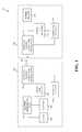
- FIG. 1is a block diagram of an example wireless power transfer system in accordance with an embodiment described herein.
- FIG. 2depicts a flowchart of a method for wirelessly transferring power from a charging station to a portable electronic device in accordance with an embodiment described herein.
- FIG. 3depicts a flowchart of a method for wirelessly receiving power from a charging station by a portable electronic device in accordance with an embodiment described herein.
- FIG. 4depicts a flowchart of an additional method for wirelessly transferring power from a charging station to a portable electronic device in accordance with an embodiment described herein.
- FIG. 5depicts a flowchart of an additional method for wirelessly receiving power from a charging station by a portable electronic device in accordance with an embodiment described herein.
- FIG. 6is a block diagram of a wireless power transfer system in accordance with an embodiment described herein in which a wireless power link is established using a receiver and transmitter and a wireless communication link is established using a separate pair of transceivers.
- FIG. 7is a block diagram of a wireless power transfer system in accordance with an alternate embodiment described herein in which a wireless communication link between a portable electronic device and a charging station is unidirectional.
- FIG. 8is a block diagram of a wireless power transfer system in accordance with an alternate embodiment described herein in which a charging station includes a plurality of different communication link transceivers to facilitate the establishment of wireless communication links with a plurality of different types of portable electronic devices.
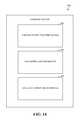
- FIG. 9depicts a flowchart of a method for increasing efficiency of wireless power transfer in accordance with an embodiment described herein.
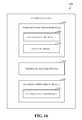
- FIGS. 10 , 12 , 14 , and 16are block diagrams of example implementations of a charging station in accordance with embodiments described herein.
- FIGS. 11A-11Ddepict respective portions of a flowchart of a method for increasing efficiency of wireless power transfer in accordance with an embodiment described herein.
- FIGS. 13 , 15 , and 17 - 21depict flowcharts of methods for increasing efficiency of wireless power transfer in accordance with embodiments described herein.
- FIG. 22is a block diagram of an example implementation of a portable electronic device in accordance with an embodiment described herein.
- references in the specification to “one embodiment,” “an embodiment,” “an example embodiment,” or the like,indicate that the embodiment described may include a particular feature, structure, or characteristic, but every embodiment may not necessarily include the particular feature, structure, or characteristic. Moreover, such phrases are not necessarily referring to the same embodiment. Furthermore, when a particular feature, structure, or characteristic is described in connection with an embodiment, it is submitted that it is within the knowledge of one skilled in the art to implement such feature, structure, or characteristic in connection with other embodiments whether or not explicitly described.
- the efficiency of a wireless power transferis defined as the magnitude of power that is consumed by a portable electronic device with respect to the wireless power transfer divided by the magnitude of power that is provided to the portable electronic device with respect to the wireless power transfer.
- the efficiency of the wireless power transfertherefore indicates the proportion of the power that is wirelessly transferred to the portable electronic device that is consumed by the portable electronic device.
- a charging stationmay begin to wirelessly transfer power to a portable electronic device via a wireless power link.
- the portable electronic devicemay be configured to send an indicator to the charging station via a wireless communication link once the charging station begins to wirelessly transfer the power to the portable electronic device.
- the indicatorspecifies information regarding the portable electronic device, which may include but is not limited to a resonant frequency of the portable electronic device, a magnitude of power requested by the portable electronic device, a magnitude of power consumed by the portable electronic power with respect to the wireless power transfer, a maximum safe power that the portable electronic device is capable of consuming without substantial risk of damaging the portable electronic device, a position of the portable electronic device, etc.
- the charging stationmay be configured to increase the efficiency of the wireless transfer of the power based on the indicator.
- a method for increasing efficiency of wireless power transferis described.
- a wireless power transferis initiated from a charging station to a portable electronic device via a wireless power link.
- Parameter(s) regarding the portable electronic deviceare received at the charging station via a wireless communication link in response to initiation of the wireless power transfer.
- Efficiency of the wireless power transferis increased based on the parameter(s).
- Another methodis described for increasing efficiency of wireless power transfer.
- poweris wirelessly transferred to a portable electronic device via a wireless power link.
- Parameter(s) received via a wireless communication link regarding the portable electronic device with respect to the wireless transfer of the powerare analyzed.
- Efficiency with respect to the wireless transfer of the poweris increased based on analysis of the parameter(s).
- Yet another methodfor increasing efficiency of wireless power transfer.
- poweris wirelessly received for a first period of time at a portable electronic device from a charging station via a wireless power link having a first transmission efficiency.
- Parameter(s) regarding the portable electronic device with respect to receipt of the power during the first period of timeare provided to the charging station via a wireless communication link.
- Poweris wirelessly received for a second period of time at the portable electronic device from the charging station via the wireless power link having a second transmission efficiency in response to providing the parameter(s) to the charging station.
- the second transmission efficiencyis greater than the first transmission efficiency.
- a systemincludes a wireless power transfer module, a parameter receipt module, and an efficiency improvement module.
- the wireless power transfer moduleis configured to initiate a wireless power transfer to a portable electronic device via a wireless power link.
- a parameter receipt moduleis configured to receive parameter(s) regarding the portable electronic device via a wireless communication link in response to initiation of the wireless power transfer.
- An efficiency improvement moduleis configured to increase efficiency of the wireless power transfer based on the parameter(s).
- the wireless power transfer moduleis configured to wirelessly transfer power to a portable electronic device via a wireless power link.
- the parameter analysis moduleis configured to analyze parameter(s) received via a wireless communication link regarding the portable electronic device with respect to the wireless transfer of the power.
- the efficiency improvement moduleis configured to increase efficiency with respect to the wireless transfer of the power based on analysis of the parameter(s).
- the wireless power receipt moduleis configured to wirelessly receive power for a first period of time from a charging station via a wireless power link having a first transmission efficiency.
- the parameter moduleis configured to provide parameter(s) regarding the system with respect to receipt of the power during the first period of time to the charging station via a wireless communication link.
- the wireless power receipt moduleis further configured to wirelessly receive power for a second period of time from the charging station via the wireless power link having a second transmission efficiency in response to providing the parameter(s) to the charging station.
- the second transmission efficiencyis greater than the first transmission efficiency.
- FIG. 1is a block diagram of an example wireless power transfer system 100 in accordance with an embodiment described herein.
- System 100includes a charging station 102 and a portable electronic device 104 .
- charging station 102is configured to wirelessly transfer power to portable electronic device 104 responsive to receipt of payment information therefrom.
- Charging station 102is also configured to manage the wireless transfer of power to portable electronic device 104 based on certain parameters and/or state information received from portable electronic device 104 .
- charging station 102includes a power source 122 connected to a wireless power/communication link transceiver 124 .
- Wireless power/communication link transceiver 124is configured to wirelessly transfer power supplied by power source 122 to a wireless power/communication link transceiver 146 associated with portable electronic device 104 via an inductive link 106 .
- inductive link 106As will be appreciated by persons skilled in the relevant art(s), such wireless power transfer may be carried out over inductive link 106 in accordance with the well-known principles of inductive coupling or resonant inductive coupling as discussed in the Background Section above.
- wireless power/communication link transceiver 124 and wireless power/communication link transceiver 146are implemented will depend on the type of inductive coupling used.
- a variety of transceiver designs based on inductive coupling and resonant inductive couplingare available in the art and thus need not be described herein.
- Charging station 102also includes a power link manager 126 connected between power source 122 and wireless power/communication link transceiver 124 .
- Power link manager 126is configured to sense when wireless power/communication link transceiver 146 associated with portable electronic device 104 is inductively coupled to wireless power/communication link transceiver 124 and is thus capable of receiving power wirelessly therefrom.
- Power link manager 126is further configured to transfer power wirelessly over inductive link 106 responsive to control signals from a communication link manager 128 .
- Power link manager 126may be further configured to monitor the amount of power that is wirelessly transferred via inductive link 106 to portable electronic device 104 .
- Communication link manager 128is connected both to power link manager 126 and to wireless power/communication link transceiver 124 .
- Communication link manager 128is configured to establish and maintain a wireless communication link with portable electronic device 104 via wireless power/communication link transceiver 124 for the purpose of obtaining payment information and other information therefrom.
- Such other informationmay include, for example, device-specific parameters associated with portable electronic device 104 such as a maximum safe power that may be transferred to portable electronic device 104 .
- Such other informationmay also include, for example, state information associated with portable electronic device 104 such an amount of power currently consumed or needed by portable electronic device 104 .
- Communication link manager 128is thus configured to use inductive link 106 for the wireless communication of data.
- communication link manager 128may be configured to carry out the wireless communication of data in accordance with any standard or proprietary induction-based data communication protocol.
- communication link manager 128may be configured to carry out the wireless communication of data in accordance with an NFC protocol as described in the Background Section above, although this example is not intended to be limiting and other standard or proprietary induction-based data communication protocols may be used.
- Communication link manager 128is further configured to transmit control signals to power link manager 126 to control whether and when power link manager 126 may transfer power wirelessly to portable electronic device 104 .
- Communication link manager 128can thus ensure that power is transferred to portable electronic device 104 only after requisite payment information has been received from portable electronic device 104 .
- Communication link manager 128can also control power link manager 126 to ensure that power is delivered to portable electronic device 104 in a manner that takes into account certain device-specific parameters such as a maximum safe power that may be transferred to portable electronic device 104 or state information such as an amount of power currently consumed or needed by portable electronic device 104 .
- portable electronic device 104within power transfer system 100 will now be described.
- portable electronic device 104includes a battery recharging unit 144 connected to wireless power/communication link transceiver 146 .
- Wireless power/communication link transceiver 146is configured to transfer wireless power received over inductive link 106 to battery recharging unit 144 , which is configured to use such power to recharge a battery 142 connected thereto.
- Battery recharging unit 144is also connected to a load 154 associated within portable electronic device 104 , which can be powered by battery 142 in a well-known manner.
- Portable electronic device 104further includes a power link monitor 148 connected between wireless power/communication link transceiver 146 and battery recharging unit 144 .
- Power link monitor 148may be configured to monitor an amount of power that is wirelessly received via inductive link 106 and to provide this information to a communication link manager 150 .
- Power link monitor 148may provide other state information to communication link manager 150 including, for example, a current state of battery 142 .
- Communication link manager 150is connected both to power link monitor 148 and to wireless power/communication link transceiver 146 .
- Communication link manager 150is configured to establish and maintain a wireless communication link with charging station 102 via wireless power/communication link transceiver 146 for the purpose of providing payment information and other information thereto.
- other informationmay include, for example, device-specific parameters associated with portable electronic device 104 , such as a maximum safe power that may be transferred to portable electronic device 104 , or state information associated with portable electronic device 104 such an amount of power currently consumed or needed by portable electronic device 104 . This state information may be based on or derived from state information provided by power link monitor 148 .
- Communication link manager 150is thus configured to use inductive link 106 for the wireless communication of data.
- communication link manager 150may be configured to carry out the wireless communication of data in accordance with any standard or proprietary induction-based data communication protocol.
- communication link manager 150may be configured to carry out the wireless communication of data in accordance with an NFC protocol as described in the Background Section above, although this example is not intended to be limiting and other standard or proprietary induction-based data communication protocols may be used.
- FIG. 2depicts a flowchart 200 of a method for wirelessly transferring power from a charging station to a portable electronic device in accordance with an embodiment described herein.
- the method of flowchart 200will now be described in reference to certain elements of example wireless transfer system 100 as described above in reference to FIG. 1 . However, the method is not limited to that implementation.
- the method of flowchart 200begins at step 202 in which power link manager 126 of charging station 102 establishes a wireless power link with portable electronic device 104 .
- Power link manager 126performs this function by allowing power to flow from power source 122 to wireless power/communication link transceiver 124 , which has the effect of creating inductive link 106 between wireless power/communication link transceiver 124 of charging station 102 and wireless power/communication link transceiver 146 of portable electronic device 104 .
- inductive link 106may be created for example based on the principles of inductive coupling or resonant inductive coupling.
- communication link manager 128 of charging station 102establishes a wireless communication link with portable electronic device 104 .
- Communication link manager 128performs this function by transmitting and/or receiving signals via wireless power/communication link transceiver 124 to/from wireless power/communication link transceiver 146 associated with portable electronic device 104 .
- the wireless communication linkis thus established via inductive link 106 .
- the wireless communication linkmay be established in accordance with any standard or proprietary inductance-based data communication protocol.
- communication link manager 128 of charging station 102receives payment information from portable electronic device 104 via the wireless communication link.
- the type of payment information that is received during step 206may vary depending on the manner in which the wireless power transfer service is to be paid for by the user of portable electronic device 104 .
- the payment informationmay include a unique account identifier, such as an account number.
- the charge to the userwill be added to a list of additional charges due from the user (e.g., the charge is to be added to a hotel bill for the user), then the payment information may include a unique identifier of the user.
- the payment informationmay include an electronic token indicating that such payment has occurred.
- the payment informationmay include an electronic funds amount that is currently available to the user/owner for obtaining the service. The electronic funds amount may be stored on portable electronic device 104 , or a card inserted or attached to portable electronic device 104 .
- step 206The foregoing description of the types of payment information that may be received during step 206 are provided by way of example only and are not intended to limit the present invention. Persons skilled in the relevant art(s) will readily appreciate that other types of payment information may be received during step 206 other than or in addition to those types described above.
- communication link manager 128After the payment information has been received by communication link manager 128 during step 206 , communication link manager 128 sends one or more control signals to power link manager 126 and, responsive to receiving the control signal(s), power link manager 126 allows power to be transferred to portable electronic device 104 over the wireless power link. This is generally shown at step 208 .
- communication link manager 128validates and/or processes the payment information prior to sending the control signal(s) to power link manager 126 .
- communication link manager 128transmits the payment information to an external entity for validation and/or processing prior to sending the control signal(s) to power link manager 126 .
- communication link manager 128may provide the payment information to a network interface within charging station 102 (not shown in FIG. 1 ) for wired or wireless communication to a network entity, such as a server, for processing and/or validation.
- power link manager 126monitors or meters the amount of power wirelessly transferred to portable electronic device 104 via the wireless power link.
- the monitored amountcan then be used to charge the user of portable electronic device 104 based on the amount of power transferred.
- the monitored amountis transmitted to an external entity so that the user of portable electronic device 104 may be charged based on the monitored amount.
- the external entitymay be, for example, a remote network entity, such as a server, or may be portable electronic device 104 .
- the establishment of the wireless power link in step 202may occur before, contemporaneously with, or after the establishment of the wireless communication link in step 204 depending upon the implementation. Furthermore, the establishment of the wireless power link may occur responsive to the establishment of the wireless communication link or vice versa. With respect to the establishment of the wireless communication link, either charging station 102 or portable electronic device 104 may act as the initiator depending upon the implementation.
- FIG. 3depicts a flowchart 300 of a method for wirelessly receiving power from a charging station by a portable electronic device in accordance with an embodiment described herein.
- the steps of flowchart 300are performed by a portable electronic device that is configured to interact with a charging station.
- the method of flowchart 300may be thought of as a counterpart method to the method of flowchart 200 .
- the method of flowchart 300begins at step 302 in which a wireless power link is established between wireless power/communication link transceiver 146 of portable electronic device 104 and wireless power/communication link transceiver 124 of charging station 102 .
- a wireless power linkis established between wireless power/communication link transceiver 146 of portable electronic device 104 and wireless power/communication link transceiver 124 of charging station 102 .
- the manner in which such a wireless power link is establishedwas discussed above in reference to step 202 of flowchart 200 .
- communication link manager 150 of portable electronic device 104establishes a wireless communication link with charging station 102 .
- Communication link manager 150performs this function by transmitting and/or receiving signals via wireless power/communication link transceiver 146 to/from wireless power/communication link transceiver 124 associated with charging station 102 .
- the wireless communication linkis thus established via inductive link 106 .
- the wireless communication linkmay be established in accordance with any standard or proprietary inductance-based data communication protocol.
- step 306communication link manager 150 of portable electronic device 104 transmits payment information to charging station 102 via the wireless communication link.
- the type of payment information that is transmitted during step 306may vary depending on the manner in which the wireless power transfer service is to be paid for by the user of portable electronic device 104 . Examples of various types of payment information were described above in reference to step 206 of flowchart 200 .
- charging station 102transfers power to portable electronic device 104 over the wireless power link.
- the transferred poweris received by wireless power/communication link transceiver 146 and applied to battery recharging unit 144 . This is generally shown at step 308 .
- the establishment of the wireless power link in step 302may occur before, contemporaneously with, or after the establishment of the wireless communication link in step 304 depending upon the implementation. Furthermore, the establishment of the wireless power link may occur responsive to the establishment of the wireless communication link or vice versa. With respect to the establishment of the wireless communication link, either charging station 102 or portable electronic device 104 may act as the initiator depending upon the implementation.
- FIG. 4depicts a flowchart 400 of an additional method for wirelessly transferring power from a charging station to a portable electronic device in accordance with an embodiment described herein.
- the method of flowchart 400will now be described in reference to certain elements of example wireless transfer system 100 as described above in reference to FIG. 1 . However, the method is not limited to that implementation.
- the method of flowchart 400begins at step 402 in which power link manager 126 of charging station 102 establishes a wireless power link with portable electronic device 104 .
- Power link manager 126performs this function by allowing power to flow from power source 122 to wireless power/communication link transceiver 124 , which has the effect of creating inductive link 106 between wireless power/communication link transceiver 124 of charging station 102 and wireless power/communication link transceiver 146 of portable electronic device 104 .
- inductive link 106may be created based on the principles of inductive coupling or resonant inductive coupling for example.
- communication link manager 128 of charging station 102establishes a wireless communication link with portable electronic device 104 .
- Communication link manager 128performs this function by transmitting and/or receiving signals via wireless power/communication link transceiver 124 to/from wireless power/communication link transceiver 146 associated with portable electronic device 104 .
- the wireless communication linkis thus established via inductive link 106 .
- the wireless communication linkmay be established in accordance with any standard or proprietary inductance-based data communication protocol.
- communication link manager 128 of charging station 102receives parameters and/or state information from portable electronic device 104 via the wireless communication link.
- the parametersmay include, for example, a maximum safe power that may be transmitted to portable electronic device 104 .
- the state informationmay include, for example, an amount of power currently consumed or needed by portable electronic device 104 .
- communication link manager 128After receiving the parameters and/or state information, communication link manager 128 sends one or more control signals to power link manager 126 and, responsive to receiving the control signal(s), power link manager 128 transfers power to portable electronic device 104 over the wireless power link in a manner that takes into account the received parameters and/or state information. This is generally shown at step 408 .
- controlling the power transfer in accordance with received parametersincludes controlling the wireless power link to ensure that the amount of power transferred over the link does not exceed a maximum safe power that may be transmitted to portable electronic device 104 .
- controlling the power transfer in accordance with received state informationincludes controlling the wireless power link to ensure that the amount of power that is transferred over the link is sufficient to recharge portable electronic device 104 or does not exceed an amount of power that is sufficient to recharge portable electronic device 104 .
- the establishment of the wireless power link in step 402may occur before, contemporaneously with, or after the establishment of the wireless communication link in step 404 depending upon the implementation. Furthermore, the establishment of the wireless power link may occur responsive to the establishment of the wireless communication link or vice versa. With respect to the establishment of the wireless communication link, either charging station 102 or portable electronic device 104 may act as the initiator depending upon the implementation.
- FIG. 5depicts a flowchart 500 of a method for wirelessly receiving power from a charging station by a portable electronic device in accordance with an embodiment described herein.
- the steps of flowchart 500are performed by a portable electronic device that is configured to interact with a charging station.
- the method of flowchart 500may be thought of as a counterpart method to the method of flowchart 400 .
- the method of flowchart 500begins at step 502 in which a wireless power link is established between wireless power/communication link transceiver 146 of portable electronic device 104 and wireless power/communication link transceiver 124 of charging station 102 .
- a wireless power linkis established between wireless power/communication link transceiver 146 of portable electronic device 104 and wireless power/communication link transceiver 124 of charging station 102 .
- the manner in which such a wireless power link is establishedwas discussed above in reference to step 402 of flowchart 400 .
- communication link manager 150 of portable electronic device 104establishes a wireless communication link with charging station 102 .
- Communication link manager 150performs this function by transmitting and/or receiving signals via wireless power/communication link transceiver 146 to/from wireless power/communication link transceiver 124 associated with charging station 102 .
- the wireless communication linkis thus established via inductive link 106 .
- the wireless communication linkmay be established in accordance with any standard or proprietary inductance-based data communication protocol.
- communication link manager 150 of portable electronic device 104transmits parameters and/or state information to charging station 102 via the wireless communication link.
- the parametersmay include, for example, a maximum safe power that may be transmitted to portable electronic device 104 and the state information may include, for example, an amount of power currently consumed or needed by portable electronic device 104 .
- communication link manager 150generates or derives the state information from information collected by power link monitor 148 .
- power link monitor 148may monitor the wireless power link to determine an amount of power transferred over the link. This amount of power may then be reported as state information to charging station 102 over the wireless communication link. Additionally, power link monitor 148 may provide other state information to communication link manager 150 including, for example, a current state of battery 142 .
- charging station 102Responsive to the receipt of the parameters and/or state information by charging station 102 , charging station 102 transfers power to portable electronic device 104 over the wireless power link, wherein the manner in which power is transferred is controlled in accordance with the parameters and/or state information.
- the transferred poweris received by wireless power/communication link transceiver 146 and applied to battery recharging unit 144 . This is generally shown at step 508 .
- the establishment of the wireless power link in step 502may occur before, contemporaneously with, or after the establishment of the wireless communication link in step 504 depending upon the implementation. Furthermore, the establishment of the wireless power link may occur responsive to the establishment of the wireless communication link or vice versa. With respect to the establishment of the wireless communication link, either charging station 102 or portable electronic device 104 may act as the initiator depending upon the implementation.
- Each of the alternative implementationsis also capable of wirelessly transferring/receiving power in accordance with the methods of flowcharts 200 , 300 , 400 and 500 as described above in reference to FIG. 2 , FIG. 3 , FIG. 4 and FIG. 5 , respectively.
- FIG. 6is a block diagram of a wireless power transfer system 600 that includes similar elements to those described in reference to FIG. 1 except that the wireless power link between the charging station and the portable electronic device is implemented using a wireless power transmitter and receiver while the wireless communication link between the charging station and the portable electronic device is implemented using a separate pair of communication link transceivers.
- wireless power transfer system 600includes a charging station 602 and a portable electronic device 604 .
- Charging station 602includes a power source 622 , a wireless power transmitter 624 , a power link manager 626 , a communication link manager 628 , and a communication link transceiver 630 .
- Portable electronic device 604includes a battery 642 , a battery recharging unit 644 , a wireless power receiver 646 , a power link monitor 648 , a communication link manager 650 , a communication link transceiver 652 , and a load 654 .
- the elements of charging station 602are configured to function in a similar manner to like-named elements of charging station 102 of FIG. 1 .
- the elements of portable electronic device 604are configured to function in a similar manner to like-named elements of portable electronic device 104 of FIG. 1 .
- Wireless power transmitter 624is configured to operate under the control of power link manager 626 to wirelessly transfer power supplied by power source 622 to wireless power receiver 646 associated with portable electronic device 604 via an inductive link 606 .
- the wireless power transfermay be carried out over inductive link 606 in accordance with the well-known principles of inductive coupling or resonant inductive coupling as discussed in the Background Section above.
- the manner in which wireless power transmitter 624 and wireless power receiver 646 are implementedwill depend on the type of inductive coupling used. A variety of transmitter and receiver designs based on inductive coupling and resonant inductive coupling are available in the art and thus need not be described herein.
- communication link transceivers 630 and 652are used to establish and maintain a wireless communication link 608 between charging station 602 and portable electronic device 604 that is separate from inductive link 606 .
- Wireless communication link 608is established for the purpose of transferring payment information and/or device-specific parameters or state information from portable electronic device 604 to charging station 602 .
- Charging station 602may then use such information in a like manner to that described above with respect to charging station 102 of FIG. 1 .
- wireless communication link 608may be established using NFC technology as described above in the Background Section.
- wireless communication link 608may be established in accordance with certain RF-based short-range communication technologies such as BluetoothTM, as described in the various standards developed and licensed by the BluetoothTM Special Interest Group, or technologies such as ZigBee® that are based on the IEEE 802.15.4 standard for wireless personal area networks (specifications describing ZigBee are publically available from the ZigBee® Alliance).
- wireless communication link 608may be established in accordance with other RF-based communication technologies such as any of the well-known IEEE 802.11 protocols.
- these examplesare not intended to be limiting, and wireless communication link 608 between charging station 602 and portable electronic device 604 may be established using a variety of other standard or propriety communication protocols.
- FIG. 7is a block diagram of a wireless power transfer system 700 that includes similar elements to those described in reference to FIG. 6 except that the wireless communication link between the portable electronic device and the charging station is unidirectional rather than bidirectional.
- wireless power transfer system 700includes a charging station 702 and a portable electronic device 704 .
- Charging station 702includes a power source 722 , a wireless power transmitter 724 , a power link manager 726 , a communication link manager 728 , and a communication link receiver 730 .
- Portable electronic device 704includes a battery 742 , a battery recharging unit 744 , a wireless power receiver 746 , a power link monitor 748 , a communication link manager 750 , a communication link transmitter 752 , and a load 754 .
- the elements of charging station 702are configured to function in a similar manner to like-named elements of charging station 602 of FIG. 6 .
- the elements of portable electronic device 704are configured to function in a similar manner to like-named elements of portable electronic device 604 of FIG. 6 .
- Communication link manager 750 within portable electronic device 704is configured to establish a unidirectional wireless communication link 708 with charging station 702 by transmitting signals via communication link transmitter 752 to communication link receiver 730 .
- This unidirectional wireless communication linkmay then be used to transmit payment information and/or device-specific parameters or state information from portable electronic device 704 to charging station 702 .
- Charging station 702may then use such information in a like manner to that described above with respect to charging station 102 of FIG. 1 .
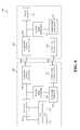
- FIG. 8is a block diagram of a wireless power transfer system 800 that includes similar elements to those described in reference to FIG. 6 except that the charging station includes a plurality of different communication link transceivers to facilitate the establishment of wireless communication links with a plurality of different types of portable electronic devices.
- wireless power transfer system 800includes a charging station 802 and a portable electronic device 804 .
- Charging station 802includes a power source 822 , a wireless power transmitter 824 , a power link manager 826 , a communication link manager 828 , and a plurality of communication link transceivers 830 A- 830 N.
- Portable electronic device 804includes a battery 842 , a battery recharging unit 844 , a wireless power receiver 846 , a power link monitor 848 , a communication link manager 850 , a communication link transceiver 852 , and a load 854 .
- the elements of charging station 802are configured to function in a similar manner to like-named elements of charging station 602 of FIG. 6 .
- the elements of portable electronic device 804are configured to function in a similar manner to like-named elements of portable electronic device 604 of FIG. 6 .
- Each of the communication link transceivers 830 A- 830 Nis configured for wireless communication in accordance with a different wireless protocol.
- first communication link transceiver 830 Amay be configured for communication in accordance with NFC
- second communication link transceiver 830 Bmay be configured for communication in accordance with BluetoothTM
- Nth communication link transceiver 830 Nmay be configured for communication in accordance with one of the IEEE 802.11 standards. This advantageously enables charging station 802 to receive payment information and device-specific parameters and/or state information from a plurality of different device types to facilitate the wireless transfer of power to such devices.
- Some example embodimentsare capable of increasing efficiency of wireless power transfer.
- the efficiency of a wireless power transferis defined as the magnitude of power that is consumed by a portable electronic device with respect to the wireless power transfer divided by the magnitude of power that is provided to the portable electronic device with respect to the wireless power transfer.
- the efficiency of the wireless power transfertherefore indicates the proportion of the power that is wirelessly transferred to the portable electronic device that is consumed by the portable electronic device.
- a charging stationbegins to wirelessly transfer power to a portable electronic device (e.g., portable electronic device 104 , 604 , 704 , or 804 ) via a wireless power link (e.g., link 106 , 606 , 706 , or 806 ).
- the portable electronic devicesends an indicator to the charging station via a wireless communication link (e.g., link 106 , 608 , 708 , or 808 ) once the charging station begins to wirelessly transfer the power to the portable electronic device.
- the indicatorspecifies information regarding the portable electronic device, which may include but is not limited to a resonant frequency of the portable electronic device, a magnitude of power requested by the portable electronic device, a magnitude of power consumed by the portable electronic power with respect to the wireless power transfer, a maximum safe power that the portable electronic device is capable of consuming without substantial risk of damaging the portable electronic device, a position of the portable electronic device, etc.
- the charging stationincreases the efficiency of the wireless transfer of the power based on the indicator.
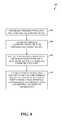
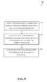
- FIG. 9depicts a flowchart 900 of a method for increasing efficiency of wireless power transfer in accordance with an embodiment described herein.
- Flowchart 900may be performed by charging station 102 , 602 , 702 , or 802 of respective wireless power transfer system 100 , 600 , 700 , or 800 shown in respective FIG. 1 , 6 , 7 , or 8 , for example.
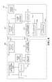
- flowchart 900is described with respect to a charging system 1000 shown in FIG. 10 , which is an example of a charging station 102 , 602 , 702 , or 802 , according to an embodiment.
- charging station 1000includes a wireless power transfer module 1002 , a parameter receipt module 1004 , and an efficiency improvement module 1006 . Further structural and operational embodiments will be apparent to persons skilled in the relevant art(s) based on the discussion regarding flowchart 900 .
- Flowchart 900is described as follows.
- step 902a wireless power transfer is initiated from a charging station to a portable electronic device via a wireless power link.
- the wireless power transfermay be performed in accordance with an inductive coupling technique, a resonant inductive coupling technique, or any other suitable technique.
- wireless power transfer module 1002initiates the wireless power transfer via the wireless power link.
- At step 904at least one parameter regarding the portable electronic device is received at the charging station via a wireless communication link.
- the at least one parametermay be received via the wireless communication link in accordance with a Near Field Communication (NFC) protocol, a BluetoothTM protocol, a ZigBee® protocol, an IEEE 802.11 protocol, or any other suitable protocol.
- NFCNear Field Communication
- the wireless power link and the wireless communication linkmay be implemented as separate links or as a common link.
- the wireless power link and the wireless communication linkmay be inductive links, though the scope of the example embodiments is not limited in this respect.
- parameter receipt module 1004receives the at least one parameter.
- efficiency of the wireless power transferis increased based on the at least one first parameter.
- efficiency improvement module 1006increases the efficiency of the wireless power transfer.
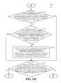
- FIGS. 11A-11Ddepict respective portions of a flowchart 1100 of a method for increasing efficiency of wireless power transfer in accordance with an embodiment described herein.
- Flowchart 1100may be performed by charging station 102 , 602 , 702 , or 802 of respective wireless power transfer system 100 , 600 , 700 , or 800 shown in respective FIG. 1 , 6 , 7 , or 8 , for example.
- flowchart 1100is described with respect to a charging system 1200 shown in FIG. 12 , which is an example of a charging station 102 , 602 , 702 , or 802 , according to an embodiment.
- charging station 1200includes a wireless power transfer module 1202 , a parameter receipt module 1204 , a parameter determination module 1206 , a frequency comparison module 1208 , an efficiency improvement module 1210 , a power comparison module 1212 , and an orientation determination module 1214 .
- Flowchart 1100is described as follows.
- step 1102a wireless power transfer is initiated from a charging station to a portable electronic device via a wireless power link.
- wireless power transfer module 1202initiates the wireless power transfer via the wireless power link.
- parameter determination module 1206determines whether a frequency parameter that specifies the resonant frequency of the portable electronic device is received. For instance, parameter receipt module 1204 may receive the frequency parameter. If the frequency parameter that specifies the resonant frequency of the portable electronic device is received via the wireless communication link, flow continues to step 1108 . Otherwise, flow continues to step 1110 .
- the wireless power link and the wireless communication linkare established via a common inductive link. According to another example embodiment, the wireless power link and the wireless communication link are established via respective inductive links.
- These example embodimentsare provided for illustrative purposes and are not intended to be limiting. For instance, the wireless power link and the wireless communication link need not necessarily be inductive links.
- the frequency parametermay specify the resonant frequency of the portable electronic device in relative terms with respect to a reference frequency or in absolute terms.
- the frequency parametermay specify a resonant frequency that is 5 megahertz (MHz) in relative terms by specifying the resonant frequency to be 3 MHz with respect to a reference frequency of 2 MHz.
- the frequency parametermay specify the same resonant frequency of 5 MHz in absolute terms to be 5 MHz, such that the resonant frequency is not specified with respect to a reference frequency.
- a reference frequencymay be any suitable frequency.
- a non-radiative magnetic fieldwhich oscillates at an oscillating frequency, may mediate the wireless power transfer.
- the charging stationmay generate the non-radiative magnetic field, and power may be wirelessly transferred from the charging station to the portable electronic device through inductive coupling and/or resonant inductive coupling.
- the oscillating frequency at which the non-radiative magnetic field oscillatesmay serve as the reference frequency.
- frequency comparison module 1208determines whether the frequency at which the non-radiative magnetic field oscillates is substantially equal to the resonant frequency of the portable electronic device. If the frequency at which the non-radiative magnetic field oscillates is substantially equal to the resonant frequency of the portable electronic device, flow continues to step 1110 . Otherwise, flow continues to step 1108 .
- the frequency at which the non-radiative magnetic field oscillatesis changed to be substantially equal to the resonant frequency of the portable electronic device.
- efficiency improvement module 1210changes the frequency at which the non-radiative magnetic field oscillates. It will be recognized that steps 1106 and 1108 may be omitted if a non-radiative field does not mediate the wireless power transfer.
- the power parametermay specify the magnitude of power requested by the portable electronic device in relative terms with respect to a reference magnitude of power or in absolute terms.
- the magnitude of power provided to the portable electronic device with respect to the wireless power transfer from the charging stationmay serve as the reference magnitude of power.
- parameter determination module 1206determines whether a power parameter that specifies a magnitude requested by the portable electronic device is received via the wireless communication link. For instance, parameter receipt module 1204 may receive the power parameter. If a power parameter that specifies a magnitude of power requested by the portable electronic device is received, flow continues to step 1112 shown in FIG. 11B . Otherwise, flow continues to step 1120 shown in FIG. 11C .
- power comparison module 1212determines whether the magnitude of power that is provided by the charging station with respect to the wireless power transfer is greater than the magnitude of power requested by the portable electronic device. If the magnitude of power that is provided by the charging station with respect to the wireless power transfer is greater than the magnitude of power requested by the portable electronic device, flow continues to step 1114 . Otherwise, flow continues to step 1116 .
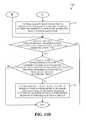
- step 1114the magnitude of power that is provided by the charging station with respect to the wireless power transfer is reduced to be substantially equal to the magnitude of power requested by the portable electronic device.
- efficiency improvement module 1210reduces the magnitude of power that is provided by the charging station with respect to the wireless power transfer to be substantially equal to the magnitude of power requested by the portable electronic device.
- power comparison module 1212determines whether the magnitude of power that is provided by the charging station with respect to the wireless power transfer is less than the magnitude of power requested by the portable electronic device. If the magnitude of power that is provided by the charging station with respect to the wireless power transfer is less than the magnitude of power requested by the portable electronic device, flow continues to step 1118 . Otherwise, flow continues to step 1120 , which is shown in FIG. 11C .
- the magnitude of power that is provided by the charging station with respect to the wireless power transferis increased to be substantially equal to the magnitude of power requested by the portable electronic device.
- efficiency improvement module 1210increases the magnitude of power that is provided by the charging station with respect to the wireless power transfer to be substantially equal to the magnitude of power requested by the portable electronic device.
- step 1118need not necessarily be performed in response to an affirmative determination at step 1116 .
- step 1120a determination is made whether a power parameter that specifies a magnitude of power consumed by the portable electronic device with respect to the wireless power transfer is received via the wireless communication link.
- the power parametermay specify the magnitude of power consumed by the portable electronic device in relative terms with respect to a reference magnitude of power or in absolute terms.
- the magnitude of power provided to the portable electronic device with respect to the wireless power transfer from the charging stationmay serve as the reference magnitude of power.
- parameter determination module 1206determines whether a power parameter that specifies the magnitude of power consumed by the portable electronic device with respect to the wireless power transfer is received via the wireless communication link. For instance, parameter receipt module 1204 may receive the power parameter. If a power parameter that specifies the magnitude of power consumed by the portable electronic device with respect to the wireless power transfer is received, flow continues to step 1122 . Otherwise, flow continues to step 1126 .
- power comparison module 1212determines whether the magnitude of power that is provided by the charging station with respect to the wireless power transfer is greater than the magnitude of power consumed by the portable electronic device with respect to the wireless power transfer. If the magnitude of power that is provided by the charging station with respect to the wireless power transfer is greater than the magnitude of power consumed by the portable electronic device with respect to the wireless power transfer, flow continues to step 1124 . Otherwise, flow continues to step 1126 .
- the magnitude of power that is provided by the charging station with respect to the wireless power transferis reduced to be substantially equal to the magnitude of power consumed by the portable electronic device with respect to the wireless power transfer.
- efficiency improvement module 1210reduces the magnitude of power that is provided by the charging station with respect to the wireless power transfer.
- parameter determination module 1206determines whether a power parameter that specifies the maximum safe power is received via the wireless communication link. For instance, parameter receipt module 1204 may receive the power parameter. If a power parameter that specifies the maximum safe power is received, flow continues to step 1128 , which is shown in FIG. 11D . Otherwise, flow continues to step 1130 , which is also shown in FIG. 11D .
- the substantial risk of damagemay be defined as a relatively high likelihood that performance of the portable electronic device will become substantially hindered, that the portable electronic device will become inoperable, or any other suitable definition.
- the power parametermay specify the maximum safe power in relative terms with respect to a reference magnitude of power or in absolute terms.
- the magnitude of power provided to the portable electronic device with respect to the wireless power transfer from the charging stationmay serve as the reference magnitude of power.
- the magnitude of power that is provided by the charging station with respect to the wireless power transferis controlled to be no greater than the maximum safe power. For instance, if the magnitude of power that is provided by the charging station with respect to the wireless power transfer is greater than the maximum safe power before performance of step 1128 , the magnitude of power that is provided by the charging station with respect to the wireless power transfer may be reduced at step 1128 to be no greater than the maximum safe power. If the magnitude of power that is provided by the charging station with respect to the wireless power transfer is less than or equal to the maximum safe power before performance of step 1128 , the magnitude of power that is provided by the charging station with respect to the wireless power transfer may be maintained at step 1128 to be no greater than the maximum safe power. In an example implementation, efficiency improvement module 1210 controls the magnitude of power that is provided by the charging station with respect to the wireless power to be no greater than the maximum safe power.
- the position parametermay specify the position of the portable electronic device in relative terms with respect to a reference position or in absolute terms.
- the position of the charging stationmay serve as the reference position.
- parameter determination module 1206determines whether a position parameter that specifies a position of the portable electronic device is received via the wireless communication link. If a position parameter that specifies a position of the portable electronic device is received, flow continues to step 1136 . Otherwise, flowchart 1100 ends.
- the transfer elementmay be a coil through which a current is provided to generate the magnetic field for performing the wireless power transfer.
- orientation determination module 1214determines whether the orientation of the transfer element is optimized with respect to the position of the portable electronic device. If the orientation of the transfer element is optimized with respect to the position of the portable electronic device, flowchart 1100 ends. Otherwise, flow continues to step 1134 .
- the orientation of the transfer elementis changed based on the position parameter to increase inductive coupling between the transfer element of the charging station and a receiving element of the portable electronic device.
- changing the orientation of the transfer elementmay include but is not limited to moving the transfer element vertically, horizontally, or in another direction; rotating the transfer element; etc.
- efficiency improvement module 1210changes the orientation of the transfer element. It will be recognized that steps 1130 , 1132 , and 1134 may be omitted if the charging station does not generate a magnetic field for performing the wireless power transfer.
- one or more steps 1102 , 1104 , 1106 , 1108 , 1110 , 1112 , 1114 , 1116 , 1118 , 1120 , 1122 , 1124 , 1126 , 1128 , 1130 , 1132 , and/or 1134 of flowchart 1100may not be performed.
- steps in addition to or in lieu of steps 1102 , 1104 , 1106 , 1108 , 1110 , 1112 , 1114 , 1116 , 1118 , 1120 , 1122 , 1124 , 1126 , 1128 , 1130 , 1132 , and/or 1134may be performed.
- charging station 1200may not include one or more of wireless power transfer module 1202 , parameter receipt module 1204 , parameter determination module 1206 , frequency comparison module 1208 , efficiency improvement module 1210 , power comparison module 1212 , and/or orientation determination module 1214 .
- charging station 1200may include modules in addition to or in lieu of wireless power transfer module 1202 , parameter receipt module 1204 , parameter determination module 1206 , frequency comparison module 1208 , efficiency improvement module 1210 , power comparison module 1212 , and/or orientation determination module 1214 .
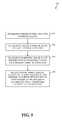
- FIG. 13depicts a flowchart 1300 of a method for increasing efficiency of wireless power transfer in accordance with an embodiment described herein.
- Flowchart 1300may be performed by charging station 102 , 602 , 702 , or 802 of respective wireless power transfer system 100 , 600 , 700 , or 800 shown in respective FIG. 1 , 6 , 7 , or 8 , for example.
- flowchart 1300is described with respect to a charging system 1400 shown in FIG. 14 , which is an example of a charging station 102 , 602 , 702 , or 802 , according to an embodiment.
- charging station 1400includes a wireless power transfer module 1402 , a parameter analysis module 1404 , and an efficiency improvement module 1406 . Further structural and operational embodiments will be apparent to persons skilled in the relevant art(s) based on the discussion regarding flowchart 1300 . Flowchart 1300 is described as follows.
- step 1302power is wirelessly transferred to a portable electronic device via a wireless power link.
- wireless power transfer module 1402wirelessly transfers the power to the portable electronic device via the wireless power link.
- a parameter received via a wireless communication link regarding the portable electronic device with respect to the wireless transfer of the poweris analyzed.
- the analysismay include but is not limited to comparing the parameter to a reference parameter to determine whether the parameter and the reference parameter are substantially same; comparing the parameter to a range of parameters to determine whether the parameter is within the range; comparing the parameter to a threshold to determine whether the parameter reaches the threshold; perform a mathematical operation with respect to the parameter to estimate the efficiency with respect to the wireless transfer of power; etc.
- parameter analysis module 1404analyzes the parameter received via the wireless communication link.
- efficiency with respect to the wireless power transfer of the poweris increased based on analysis of the parameter.
- efficiency improvement module 1406increases the efficiency with respect to the wireless transfer of the power.
- FIG. 15depicts a flowchart 1500 of a method for increasing efficiency of wireless power transfer in accordance with an embodiment described herein.
- Flowchart 1500may be performed by charging station 102 , 602 , 702 , or 802 of respective wireless power transfer system 100 , 600 , 700 , or 800 shown in respective FIG. 1 , 6 , 7 , or 8 , for example.
- flowchart 1500is described with respect to a charging system 1600 shown in FIG. 16 , which is an example of a charging station 102 , 602 , 702 , or 802 , according to an embodiment.
- charging station 1600includes a wireless power transfer module 1602 , a parameter analysis module 1604 , and an efficiency improvement module 1606 .
- Wireless power transfer module 1602includes a field generation module 1608 and a coupling module 1610 .
- Efficiency improvement module 1606includes a field manipulation module 1612 .
- the method of flowchart 1500begins at step 1502 .
- a magnetic fieldis generated.
- field generation module 1608generates the magnetic field.
- field generation module 1608may include coil through which a current is provided to generate the magnetic field.
- the fieldmay be a non-radiative magnetic field, though the scope of the example embodiments is not limited in this respect.
- poweris wirelessly transferred to a portable electronic device via a wireless power link using the magnetic field.
- the magnetic fieldmay couple with a coil in the portable electronic device that is configured to be responsive to the magnetic field.
- the powermay be wirelessly transferred in accordance with an inductive coupling technique, a resonant inductive coupling technique, or any other suitable technique.
- coupling module 1610wirelessly transfers the power to the portable electronic device.
- a parameter received via a wireless communication link regarding the portable electronic device with respect to the wireless transfer of the poweris analyzed.
- parameter analysis module 1604analyzes the parameter received via the wireless communication link.
- a characteristic of the magnetic fieldis changed to increase efficiency with respect to the wireless transfer of the power based on analysis of the parameter.
- the characteristicmay include but is not limited to a magnitude of the magnetic field, a directionality associated with the magnetic field, a frequency at which the magnetic field oscillates, etc.
- field manipulation module 1612changes the characteristic of the magnetic field to increase the efficiency with respect to the wireless transfer of the power.
- FIGS. 17-21depict flowcharts 1700 , 1800 , 1900 , 2000 , and 2100 of methods for increasing efficiency of wireless power transfer in accordance with embodiments described herein.
- Each of flowcharts 1700 , 1800 , 1900 , 2000 , and 2100may be performed by portable electronic device 104 , 604 , 704 , or 804 of respective wireless power transfer system 100 , 600 , 700 , or 800 shown in respective FIG. 1 , 6 , 7 , or 8 , for example.
- flowcharts 1700 , 1800 , 1900 , 2000 , and 2100are described with respect to portable electronic device 2200 shown in FIG. 22 , which is an example of a portable electronic device 104 , 604 , 704 , or 804 , according to an embodiment.
- portable electronic device 2200includes a wireless power receipt module 2202 and a parameter module 2204 .
- a wireless power receipt module 2202includes a wireless power receipt module 2202 and a parameter module 2204 .
- Further structural and operational embodimentswill be apparent to persons skilled in the relevant art(s) based on the discussion regarding flowcharts 1700 , 1800 , 1900 , 2000 , and 2100 . Flowcharts 1700 , 1800 , 1900 , 2000 , and 2100 are described in the following discussion.
- step 1702power is wirelessly received for a first period of time at a portable electronic device from a charging station via a wireless power link having a first transmission efficiency.
- Wirelessly receiving power for the first period of timemay be performed in accordance with an inductive coupling technique, a resonant inductive coupling technique, or any other suitable technique.
- wireless power receipt module 2202wirelessly receives power for the first period of time.
- At step 1704at least one parameter regarding the portable electronic device with respect to receipt of power during the first period of time is provided to the charging station via a wireless communication link.
- the at least one parametermay be provided to the charging station via the wireless communication link in accordance with a Near Field Communication (NFC) protocol, a BluetoothTM protocol, a ZigBee® protocol, an IEEE 802.11 protocol, or any other suitable protocol.
- NFCNear Field Communication
- the wireless power link and the wireless communication linkmay be implemented as separate links or as a common link.
- the wireless power link and the wireless communication linkmay be inductive links, though the scope of the example embodiments is not limited in this respect.
- parameter module 2204provides the at least one parameter to the charging station.
- step 1706power is wirelessly received for a second period of time at the portable electronic device from the charging station via the wireless power link having a second transmission efficiency that is greater than the first transmission efficiency in response to providing the at least one parameter to the charging station.
- Wirelessly receiving power for the second period of timemay be performed in accordance with an inductive coupling technique, a resonant inductive coupling technique, or any other suitable technique.
- wireless power receipt module 2202wirelessly receives power for the second period of time.
- step 1802power is wirelessly received for a first period of time at a portable electronic device from a charging station via a wireless power link having a first transmission efficiency.
- wireless power receipt module 2202wirelessly receives power for the first period of time.
- a frequency parameter that specifies a resonant frequency of the portable electronic deviceis provided to charging station via a wireless communication link.
- the frequency parametermay specify the resonant frequency in relative terms with respect to a reference frequency or in absolute terms.
- parameter module 2204provides the frequency parameter to the charging station.
- step 1806power is wirelessly received for a second period of time at the portable electronic device from the charging station via the wireless power link having a second transmission efficiency that is greater than the first transmission efficiency in response to providing the frequency parameter to the charging station.
- the first efficiencyis based on resonant inductive coupling of a first coil in the portable electronic device with a second coil in the charging station that generates a non-radiative magnetic field oscillating at a first frequency that is not substantially same as the resonant frequency of the portable electronic device.
- the second efficiencyis based on resonant inductive coupling of the first coil in the portable electronic device with the second coil in the charging station that generates a non-radiative magnetic field oscillating at a second frequency that is substantially same as the resonant frequency of the portable electronic device.
- wireless power receipt module 2202wirelessly receives power for the second period of time.
- the method of flowchart 1900begins at step 1902 .
- a magnitude of power that is greater than a reference magnitude of poweris wirelessly received for a first period of time at a portable electronic device from a charging station via a wireless power link having a first transmission efficiency.
- wireless power receipt module 2202wirelessly receives the magnitude of power that is greater than the reference magnitude of power for the first period of time.
- a power parameteris provided to the charging station via a wireless communication link.
- the power parameterspecifies the reference magnitude of power as being requested by the portable electronic device.
- the power parametermay specify the reference magnitude of power in relative terms with respect to a second reference magnitude of power or in absolute terms.
- the magnitude of power wirelessly received for the first period of time at the portable electronic devicemay serve as the second reference magnitude of power.
- parameter module 2204provides the power parameter to the charging station.
- a magnitude of power that is substantially same as the reference magnitude of poweris wirelessly received for a second period of time at the portable electronic device from the charging station via the wireless power link having a second transmission efficiency that is greater than the first transmission efficiency in response to providing the power parameter to the charging station.
- wireless power receipt module 2202wirelessly receives the magnitude of power that is substantially same as the reference magnitude of power for the second period of time.
- step 2002a magnitude of power is wirelessly received at a portable electronic device for a first period of time from a charging station via a wireless power link having a first transmission efficiency.
- the magnitude of power wirelessly received for the first period of timeis greater than a magnitude of power consumed by the portable electronic device for the first period of time.
- wireless power receipt module 2202wirelessly receives the magnitude of power for the first period of time.
- a power parameter that specifies the magnitude of power consumed by the portable electronic device during the first period of timeis provided to the charging station via a wireless communication link.
- the power parametermay specify the magnitude of power consumed by the portable electronic device during the first period of time in relative terms with respect to a reference magnitude of power or in absolute terms.
- the magnitude of power wirelessly received at the portable electronic device for the first period of timemay serve as the reference magnitude of power.
- parameter module 2204provides the power parameter to the charging station.
- a magnitude of poweris wirelessly received at the portable electronic device for a second period of time from the charging station via the wireless power link having a second transmission efficiency that is greater than the first transmission efficiency in response to providing the power parameter to the charging station.
- the magnitude of power wirelessly received for the second period of timeis substantially same as the magnitude of power consumed by the portable electronic device for the second period of time.
- wireless power receipt module 2202wirelessly receives the magnitude of power for the second period of time.
- step 2102a magnitude of power that is greater than a maximum safe power, which a portable electronic device is capable of consuming without substantial risk of damaging the portable electronic device, is wirelessly received for a first period of time at the portable electronic device from a charging station via a wireless power link having a first transmission efficiency.
- wireless power receipt module 2202wirelessly receives the magnitude of power for the first period of time.
- a power parameter that specifies the maximum safe poweris provided to the charging station via a wireless communication link.
- the power parametermay specify the maximum safe power in relative terms with respect to a reference magnitude of power or in absolute terms. For example, the magnitude of power wirelessly received for the first period of time at the portable electronic device may serve as the reference magnitude of power.
- parameter module 2204provides the power parameter that specifies the maximum safe power to the charging station.
- a magnitude of power that is no greater than the maximum safe poweris wirelessly received for a second period of time at the portable electronic device from the charging station via the wireless power link having a second transmission efficiency that is greater than the first transmission efficiency in response to providing the power parameter to the charging station.
- wireless power receipt module 2202wirelessly receives the magnitude of power for the second period of time.
Landscapes
- Engineering & Computer Science (AREA)
- Power Engineering (AREA)
- Computer Networks & Wireless Communication (AREA)
- Transportation (AREA)
- Mechanical Engineering (AREA)
- Manufacturing & Machinery (AREA)
- Chemical & Material Sciences (AREA)
- Chemical Kinetics & Catalysis (AREA)
- Electrochemistry (AREA)
- General Chemical & Material Sciences (AREA)
- Charge And Discharge Circuits For Batteries Or The Like (AREA)
- Telephone Function (AREA)
Abstract
Description
Claims (21)
Priority Applications (3)
| Application Number | Priority Date | Filing Date | Title |
|---|---|---|---|
| US12/580,689US8427100B2 (en) | 2009-02-06 | 2009-10-16 | Increasing efficiency of wireless power transfer |
| US13/856,298US8803476B2 (en) | 2009-02-06 | 2013-04-03 | Increasing efficiency of wireless power transfer |
| US13/856,305US8816638B2 (en) | 2009-02-06 | 2013-04-03 | Increasing efficiency of wireless power transfer |
Applications Claiming Priority (3)
| Application Number | Priority Date | Filing Date | Title |
|---|---|---|---|
| US15055409P | 2009-02-06 | 2009-02-06 | |
| US12/421,762US20100201310A1 (en) | 2009-02-06 | 2009-04-10 | Wireless power transfer system |
| US12/580,689US8427100B2 (en) | 2009-02-06 | 2009-10-16 | Increasing efficiency of wireless power transfer |
Related Parent Applications (1)
| Application Number | Title | Priority Date | Filing Date |
|---|---|---|---|
| US12/421,762Continuation-In-PartUS20100201310A1 (en) | 2009-02-06 | 2009-04-10 | Wireless power transfer system |
Related Child Applications (2)
| Application Number | Title | Priority Date | Filing Date |
|---|---|---|---|
| US13/856,305DivisionUS8816638B2 (en) | 2009-02-06 | 2013-04-03 | Increasing efficiency of wireless power transfer |
| US13/856,298ContinuationUS8803476B2 (en) | 2009-02-06 | 2013-04-03 | Increasing efficiency of wireless power transfer |
Publications (2)
| Publication Number | Publication Date |
|---|---|
| US20100201313A1 US20100201313A1 (en) | 2010-08-12 |
| US8427100B2true US8427100B2 (en) | 2013-04-23 |
Family
ID=42539876
Family Applications (3)
| Application Number | Title | Priority Date | Filing Date |
|---|---|---|---|
| US12/580,689Active2030-07-01US8427100B2 (en) | 2009-02-06 | 2009-10-16 | Increasing efficiency of wireless power transfer |
| US13/856,305ActiveUS8816638B2 (en) | 2009-02-06 | 2013-04-03 | Increasing efficiency of wireless power transfer |
| US13/856,298ActiveUS8803476B2 (en) | 2009-02-06 | 2013-04-03 | Increasing efficiency of wireless power transfer |
Family Applications After (2)
| Application Number | Title | Priority Date | Filing Date |
|---|---|---|---|
| US13/856,305ActiveUS8816638B2 (en) | 2009-02-06 | 2013-04-03 | Increasing efficiency of wireless power transfer |
| US13/856,298ActiveUS8803476B2 (en) | 2009-02-06 | 2013-04-03 | Increasing efficiency of wireless power transfer |
Country Status (1)
| Country | Link |
|---|---|
| US (3) | US8427100B2 (en) |
Cited By (10)
| Publication number | Priority date | Publication date | Assignee | Title |
|---|---|---|---|---|
| US20130072115A1 (en)* | 2011-03-22 | 2013-03-21 | Douglas Howard Dobyns | Techniques for Wireless Communication of Proximity Based Content |
| US20140194099A1 (en)* | 2013-01-08 | 2014-07-10 | Samsung Electronics Co., Ltd. | Method and apparatus for displaying information about wireless charging pad in electronic device |
| US8880100B2 (en) | 2011-03-23 | 2014-11-04 | Radium, Inc. | Proximity based social networking |
| US20150091508A1 (en)* | 2013-10-01 | 2015-04-02 | Blackberry Limited | Bi-directional communication with a device under charge |
| US9400985B2 (en) | 2010-11-08 | 2016-07-26 | Radeum, Inc. | Techniques for wireless communication of proximity based content |
| US9621228B2 (en) | 2014-08-29 | 2017-04-11 | Freelinc Technologies | Spatially aware communications using radio frequency (RF) communications standards |
| EP2875586B1 (en) | 2013-08-07 | 2018-01-17 | Koninklijke Philips N.V. | Wireless inductive power transfer |
| US10164685B2 (en) | 2014-12-31 | 2018-12-25 | Freelinc Technologies Inc. | Spatially aware wireless network |
| US10490013B2 (en)* | 2011-08-01 | 2019-11-26 | Elwha Llc | Vending devices having ad-watching as consideration |
| US11784502B2 (en) | 2014-03-04 | 2023-10-10 | Scramoge Technology Limited | Wireless charging and communication board and wireless charging and communication device |
Families Citing this family (319)
| Publication number | Priority date | Publication date | Assignee | Title |
|---|---|---|---|---|
| US7825543B2 (en) | 2005-07-12 | 2010-11-02 | Massachusetts Institute Of Technology | Wireless energy transfer |
| US7952322B2 (en) | 2006-01-31 | 2011-05-31 | Mojo Mobility, Inc. | Inductive power source and charging system |
| US11201500B2 (en) | 2006-01-31 | 2021-12-14 | Mojo Mobility, Inc. | Efficiencies and flexibilities in inductive (wireless) charging |
| US8169185B2 (en) | 2006-01-31 | 2012-05-01 | Mojo Mobility, Inc. | System and method for inductive charging of portable devices |
| US7948208B2 (en) | 2006-06-01 | 2011-05-24 | Mojo Mobility, Inc. | Power source, charging system, and inductive receiver for mobile devices |
| US11329511B2 (en) | 2006-06-01 | 2022-05-10 | Mojo Mobility Inc. | Power source, charging system, and inductive receiver for mobile devices |
| US8115448B2 (en) | 2007-06-01 | 2012-02-14 | Michael Sasha John | Systems and methods for wireless power |
| US9421388B2 (en) | 2007-06-01 | 2016-08-23 | Witricity Corporation | Power generation for implantable devices |
| US20110050164A1 (en) | 2008-05-07 | 2011-03-03 | Afshin Partovi | System and methods for inductive charging, and improvements and uses thereof |
| CN102099958B (en) | 2008-05-14 | 2013-12-25 | 麻省理工学院 | Wireless power transfer including interference enhancement |
| US9105959B2 (en) | 2008-09-27 | 2015-08-11 | Witricity Corporation | Resonator enclosure |
| US9601261B2 (en) | 2008-09-27 | 2017-03-21 | Witricity Corporation | Wireless energy transfer using repeater resonators |
| US8461720B2 (en) | 2008-09-27 | 2013-06-11 | Witricity Corporation | Wireless energy transfer using conducting surfaces to shape fields and reduce loss |
| US8471410B2 (en) | 2008-09-27 | 2013-06-25 | Witricity Corporation | Wireless energy transfer over distance using field shaping to improve the coupling factor |
| US9035499B2 (en) | 2008-09-27 | 2015-05-19 | Witricity Corporation | Wireless energy transfer for photovoltaic panels |
| US8723366B2 (en) | 2008-09-27 | 2014-05-13 | Witricity Corporation | Wireless energy transfer resonator enclosures |
| US8400017B2 (en) | 2008-09-27 | 2013-03-19 | Witricity Corporation | Wireless energy transfer for computer peripheral applications |
| US8587155B2 (en) | 2008-09-27 | 2013-11-19 | Witricity Corporation | Wireless energy transfer using repeater resonators |
| US9544683B2 (en) | 2008-09-27 | 2017-01-10 | Witricity Corporation | Wirelessly powered audio devices |
| US9106203B2 (en) | 2008-09-27 | 2015-08-11 | Witricity Corporation | Secure wireless energy transfer in medical applications |
| US8686598B2 (en) | 2008-09-27 | 2014-04-01 | Witricity Corporation | Wireless energy transfer for supplying power and heat to a device |
| US8669676B2 (en) | 2008-09-27 | 2014-03-11 | Witricity Corporation | Wireless energy transfer across variable distances using field shaping with magnetic materials to improve the coupling factor |
| US9184595B2 (en) | 2008-09-27 | 2015-11-10 | Witricity Corporation | Wireless energy transfer in lossy environments |
| US8928276B2 (en) | 2008-09-27 | 2015-01-06 | Witricity Corporation | Integrated repeaters for cell phone applications |
| US8466583B2 (en) | 2008-09-27 | 2013-06-18 | Witricity Corporation | Tunable wireless energy transfer for outdoor lighting applications |
| US8441154B2 (en) | 2008-09-27 | 2013-05-14 | Witricity Corporation | Multi-resonator wireless energy transfer for exterior lighting |
| US8963488B2 (en) | 2008-09-27 | 2015-02-24 | Witricity Corporation | Position insensitive wireless charging |
| US8482158B2 (en) | 2008-09-27 | 2013-07-09 | Witricity Corporation | Wireless energy transfer using variable size resonators and system monitoring |
| US8946938B2 (en) | 2008-09-27 | 2015-02-03 | Witricity Corporation | Safety systems for wireless energy transfer in vehicle applications |
| US8497601B2 (en) | 2008-09-27 | 2013-07-30 | Witricity Corporation | Wireless energy transfer converters |
| US8569914B2 (en) | 2008-09-27 | 2013-10-29 | Witricity Corporation | Wireless energy transfer using object positioning for improved k |
| US8410636B2 (en) | 2008-09-27 | 2013-04-02 | Witricity Corporation | Low AC resistance conductor designs |
| US8957549B2 (en) | 2008-09-27 | 2015-02-17 | Witricity Corporation | Tunable wireless energy transfer for in-vehicle applications |
| US8461721B2 (en) | 2008-09-27 | 2013-06-11 | Witricity Corporation | Wireless energy transfer using object positioning for low loss |
| US9744858B2 (en) | 2008-09-27 | 2017-08-29 | Witricity Corporation | System for wireless energy distribution in a vehicle |
| US9396867B2 (en) | 2008-09-27 | 2016-07-19 | Witricity Corporation | Integrated resonator-shield structures |
| US9601270B2 (en) | 2008-09-27 | 2017-03-21 | Witricity Corporation | Low AC resistance conductor designs |
| US9577436B2 (en) | 2008-09-27 | 2017-02-21 | Witricity Corporation | Wireless energy transfer for implantable devices |
| US8933594B2 (en) | 2008-09-27 | 2015-01-13 | Witricity Corporation | Wireless energy transfer for vehicles |
| US8643326B2 (en) | 2008-09-27 | 2014-02-04 | Witricity Corporation | Tunable wireless energy transfer systems |
| US8598743B2 (en) | 2008-09-27 | 2013-12-03 | Witricity Corporation | Resonator arrays for wireless energy transfer |
| US8324759B2 (en) | 2008-09-27 | 2012-12-04 | Witricity Corporation | Wireless energy transfer using magnetic materials to shape field and reduce loss |
| US8692412B2 (en) | 2008-09-27 | 2014-04-08 | Witricity Corporation | Temperature compensation in a wireless transfer system |
| US8487480B1 (en) | 2008-09-27 | 2013-07-16 | Witricity Corporation | Wireless energy transfer resonator kit |
| US9093853B2 (en) | 2008-09-27 | 2015-07-28 | Witricity Corporation | Flexible resonator attachment |
| US9601266B2 (en) | 2008-09-27 | 2017-03-21 | Witricity Corporation | Multiple connected resonators with a single electronic circuit |
| US8912687B2 (en) | 2008-09-27 | 2014-12-16 | Witricity Corporation | Secure wireless energy transfer for vehicle applications |
| US8922066B2 (en) | 2008-09-27 | 2014-12-30 | Witricity Corporation | Wireless energy transfer with multi resonator arrays for vehicle applications |
| US9318922B2 (en) | 2008-09-27 | 2016-04-19 | Witricity Corporation | Mechanically removable wireless power vehicle seat assembly |
| US8772973B2 (en) | 2008-09-27 | 2014-07-08 | Witricity Corporation | Integrated resonator-shield structures |
| US9246336B2 (en) | 2008-09-27 | 2016-01-26 | Witricity Corporation | Resonator optimizations for wireless energy transfer |
| US8947186B2 (en) | 2008-09-27 | 2015-02-03 | Witricity Corporation | Wireless energy transfer resonator thermal management |
| US8692410B2 (en) | 2008-09-27 | 2014-04-08 | Witricity Corporation | Wireless energy transfer with frequency hopping |
| US8476788B2 (en) | 2008-09-27 | 2013-07-02 | Witricity Corporation | Wireless energy transfer with high-Q resonators using field shaping to improve K |
| US9515494B2 (en) | 2008-09-27 | 2016-12-06 | Witricity Corporation | Wireless power system including impedance matching network |
| US8907531B2 (en) | 2008-09-27 | 2014-12-09 | Witricity Corporation | Wireless energy transfer with variable size resonators for medical applications |
| EP3179640A1 (en) | 2008-09-27 | 2017-06-14 | WiTricity Corporation | Wireless energy transfer systems |
| US8587153B2 (en) | 2008-09-27 | 2013-11-19 | Witricity Corporation | Wireless energy transfer using high Q resonators for lighting applications |
| US9065423B2 (en) | 2008-09-27 | 2015-06-23 | Witricity Corporation | Wireless energy distribution system |
| US8901778B2 (en) | 2008-09-27 | 2014-12-02 | Witricity Corporation | Wireless energy transfer with variable size resonators for implanted medical devices |
| US8461722B2 (en) | 2008-09-27 | 2013-06-11 | Witricity Corporation | Wireless energy transfer using conducting surfaces to shape field and improve K |
| US8937408B2 (en) | 2008-09-27 | 2015-01-20 | Witricity Corporation | Wireless energy transfer for medical applications |
| US9160203B2 (en) | 2008-09-27 | 2015-10-13 | Witricity Corporation | Wireless powered television |
| US8552592B2 (en) | 2008-09-27 | 2013-10-08 | Witricity Corporation | Wireless energy transfer with feedback control for lighting applications |
| US8304935B2 (en) | 2008-09-27 | 2012-11-06 | Witricity Corporation | Wireless energy transfer using field shaping to reduce loss |
| US8901779B2 (en) | 2008-09-27 | 2014-12-02 | Witricity Corporation | Wireless energy transfer with resonator arrays for medical applications |
| US8629578B2 (en) | 2008-09-27 | 2014-01-14 | Witricity Corporation | Wireless energy transfer systems |
| US8362651B2 (en) | 2008-10-01 | 2013-01-29 | Massachusetts Institute Of Technology | Efficient near-field wireless energy transfer using adiabatic system variations |
| US8069100B2 (en) | 2009-01-06 | 2011-11-29 | Access Business Group International Llc | Metered delivery of wireless power |
| US8427330B2 (en)* | 2009-02-06 | 2013-04-23 | Broadcom Corporation | Efficiency indicator for increasing efficiency of wireless power transfer |
| US8427100B2 (en) | 2009-02-06 | 2013-04-23 | Broadcom Corporation | Increasing efficiency of wireless power transfer |
| US20110199045A1 (en)* | 2010-02-15 | 2011-08-18 | Convenientpower Hk Ltd | Power transfer device and method |
| US8294418B2 (en)* | 2010-02-03 | 2012-10-23 | ConvenientPower, Ltd. | Power transfer device and method |
| JP5478298B2 (en)* | 2010-02-25 | 2014-04-23 | オリンパス株式会社 | Portable wireless terminal, wireless terminal device, and wireless communication system |
| KR20110103297A (en)* | 2010-03-12 | 2011-09-20 | 삼성전자주식회사 | Wireless power charging method and device |
| WO2011156768A2 (en) | 2010-06-11 | 2011-12-15 | Mojo Mobility, Inc. | System for wireless power transfer that supports interoperability, and multi-pole magnets for use therewith |
| US9602168B2 (en) | 2010-08-31 | 2017-03-21 | Witricity Corporation | Communication in wireless energy transfer systems |
| KR101748309B1 (en)* | 2010-09-10 | 2017-06-16 | 삼성전자주식회사 | Electronic Device and Power Supply System of Electronic Device |
| JP5564412B2 (en)* | 2010-12-10 | 2014-07-30 | 株式会社日立製作所 | Wireless power transmission system, power transmission device, and power reception device |
| US9178369B2 (en)* | 2011-01-18 | 2015-11-03 | Mojo Mobility, Inc. | Systems and methods for providing positioning freedom, and support of different voltages, protocols, and power levels in a wireless power system |
| US9496732B2 (en) | 2011-01-18 | 2016-11-15 | Mojo Mobility, Inc. | Systems and methods for wireless power transfer |
| US10115520B2 (en) | 2011-01-18 | 2018-10-30 | Mojo Mobility, Inc. | Systems and method for wireless power transfer |
| US11342777B2 (en) | 2011-01-18 | 2022-05-24 | Mojo Mobility, Inc. | Powering and/or charging with more than one protocol |
| JP5703823B2 (en)* | 2011-02-21 | 2015-04-22 | ソニー株式会社 | Power transmission device, power transmission method, and power transmission system |
| JP5703822B2 (en)* | 2011-02-21 | 2015-04-22 | ソニー株式会社 | Power transmission device, power transmission method, and power transmission system |
| US20120290470A1 (en)* | 2011-05-11 | 2012-11-15 | Samsung Electro-Mechanics Company, Ltd. | Payment systems and methods for providing wireless power transfer |
| US9948145B2 (en) | 2011-07-08 | 2018-04-17 | Witricity Corporation | Wireless power transfer for a seat-vest-helmet system |
| CN108110907B (en) | 2011-08-04 | 2022-08-02 | 韦特里西提公司 | Tunable wireless power supply architecture |
| KR101813264B1 (en) | 2011-08-05 | 2017-12-29 | 삼성전자주식회사 | Wireless power transmission system, method and apparatus for power control in power transmission system |
| US9059591B2 (en)* | 2011-08-30 | 2015-06-16 | L&P Property Management Company | Docking station for inductively charged portable electronic device |
| EP2754222B1 (en) | 2011-09-09 | 2015-11-18 | Witricity Corporation | Foreign object detection in wireless energy transfer systems |
| US20130062966A1 (en) | 2011-09-12 | 2013-03-14 | Witricity Corporation | Reconfigurable control architectures and algorithms for electric vehicle wireless energy transfer systems |
| US9318257B2 (en) | 2011-10-18 | 2016-04-19 | Witricity Corporation | Wireless energy transfer for packaging |
| CA2853824A1 (en) | 2011-11-04 | 2013-05-10 | Witricity Corporation | Wireless energy transfer modeling tool |
| JP2015508987A (en) | 2012-01-26 | 2015-03-23 | ワイトリシティ コーポレーションWitricity Corporation | Wireless energy transmission with reduced field |
| US8933589B2 (en) | 2012-02-07 | 2015-01-13 | The Gillette Company | Wireless power transfer using separately tunable resonators |
| KR101902795B1 (en)* | 2012-02-21 | 2018-11-14 | 삼성전자주식회사 | Method for wireless charging and apparatus for the same |
| US9722447B2 (en) | 2012-03-21 | 2017-08-01 | Mojo Mobility, Inc. | System and method for charging or powering devices, such as robots, electric vehicles, or other mobile devices or equipment |
| US20130271069A1 (en) | 2012-03-21 | 2013-10-17 | Mojo Mobility, Inc. | Systems and methods for wireless power transfer |
| US9276645B2 (en)* | 2012-03-29 | 2016-03-01 | GM Global Technology Operations LLC | Inductive charger for providing radio frequency (“RF”) signal to a portable electric device |
| US9218031B2 (en)* | 2012-05-18 | 2015-12-22 | Dell Products, Lp | System and method for providing wireless power feedback in a wireless power delivery system |
| US9343922B2 (en) | 2012-06-27 | 2016-05-17 | Witricity Corporation | Wireless energy transfer for rechargeable batteries |
| US9509177B2 (en)* | 2012-06-29 | 2016-11-29 | Broadcom Corporation | Portable device capable of wireless power reception and transmission |
| US9806768B2 (en) | 2012-07-19 | 2017-10-31 | Samsung Electronics Co., Ltd. | Methods and device for controlling power transmission using NFC |
| US9287607B2 (en) | 2012-07-31 | 2016-03-15 | Witricity Corporation | Resonator fine tuning |
| US9595378B2 (en) | 2012-09-19 | 2017-03-14 | Witricity Corporation | Resonator enclosure |
| US9118193B2 (en)* | 2012-10-10 | 2015-08-25 | Ming-Hsiang Yeh | Bidirectional wireless charging/discharging device for portable electronic device |
| EP2909912B1 (en) | 2012-10-19 | 2022-08-10 | WiTricity Corporation | Foreign object detection in wireless energy transfer systems |
| US9229515B2 (en)* | 2012-11-14 | 2016-01-05 | Taiwan Gomet Technology Co. Ltd. | Cloud management method of electronic devices |
| US9842684B2 (en) | 2012-11-16 | 2017-12-12 | Witricity Corporation | Systems and methods for wireless power system with improved performance and/or ease of use |
| US10009065B2 (en) | 2012-12-05 | 2018-06-26 | At&T Intellectual Property I, L.P. | Backhaul link for distributed antenna system |
| US9113347B2 (en) | 2012-12-05 | 2015-08-18 | At&T Intellectual Property I, Lp | Backhaul link for distributed antenna system |
| US9137019B2 (en)* | 2013-01-07 | 2015-09-15 | Nxp, B.V. | Secure wireless charging |
| US9197095B2 (en)* | 2013-01-24 | 2015-11-24 | Electronics And Telecommunications Research Institute | Wireless power charging apparatus and method of charging the apparatus |
| US9837846B2 (en) | 2013-04-12 | 2017-12-05 | Mojo Mobility, Inc. | System and method for powering or charging receivers or devices having small surface areas or volumes |
| US20140347436A1 (en)* | 2013-05-22 | 2014-11-27 | Sony Corporation | Portable transparent display with life-size image for teleconference |
| US9999038B2 (en) | 2013-05-31 | 2018-06-12 | At&T Intellectual Property I, L.P. | Remote distributed antenna system |
| US9525524B2 (en) | 2013-05-31 | 2016-12-20 | At&T Intellectual Property I, L.P. | Remote distributed antenna system |
| JPWO2015015771A1 (en)* | 2013-07-31 | 2017-03-02 | パナソニック株式会社 | Wireless power transmission system and power transmission device |
| US9857821B2 (en) | 2013-08-14 | 2018-01-02 | Witricity Corporation | Wireless power transfer frequency adjustment |
| US20150085060A1 (en) | 2013-09-20 | 2015-03-26 | Microsoft Corporation | User experience for conferencing with a touch screen display |
| US9363476B2 (en)* | 2013-09-20 | 2016-06-07 | Microsoft Technology Licensing, Llc | Configuration of a touch screen display with conferencing |
| CN104518674A (en)* | 2013-09-27 | 2015-04-15 | 中兴通讯股份有限公司 | Adjusting method and system of non-contact transformer |
| US20150091496A1 (en)* | 2013-10-01 | 2015-04-02 | Blackberry Limited | Bi-directional communication with a device under charge |
| US20150115881A1 (en)* | 2013-10-25 | 2015-04-30 | Samsung Electro-Mechanics Co., Ltd. | Wireless power transceiver and portable terminal having the same |
| EP2868293B1 (en)* | 2013-10-30 | 2017-08-30 | Trisa Holding AG | Electrically Operated Toothbrush for Tooth Care |
| US8897697B1 (en) | 2013-11-06 | 2014-11-25 | At&T Intellectual Property I, Lp | Millimeter-wave surface-wave communications |
| US9209902B2 (en) | 2013-12-10 | 2015-12-08 | At&T Intellectual Property I, L.P. | Quasi-optical coupler |
| US10075027B2 (en) | 2014-01-14 | 2018-09-11 | Huawei Device (Dongguan) Co., Ltd. | Method and device for enabling near field communication NFC wireless charging service |
| US9780573B2 (en) | 2014-02-03 | 2017-10-03 | Witricity Corporation | Wirelessly charged battery system |
| US9952266B2 (en) | 2014-02-14 | 2018-04-24 | Witricity Corporation | Object detection for wireless energy transfer systems |
| US9892849B2 (en) | 2014-04-17 | 2018-02-13 | Witricity Corporation | Wireless power transfer systems with shield openings |
| US9842687B2 (en) | 2014-04-17 | 2017-12-12 | Witricity Corporation | Wireless power transfer systems with shaped magnetic components |
| US9837860B2 (en) | 2014-05-05 | 2017-12-05 | Witricity Corporation | Wireless power transmission systems for elevators |
| JP2017518018A (en) | 2014-05-07 | 2017-06-29 | ワイトリシティ コーポレーションWitricity Corporation | Foreign object detection in wireless energy transmission systems |
| US9954375B2 (en) | 2014-06-20 | 2018-04-24 | Witricity Corporation | Wireless power transfer systems for surfaces |
| CN107258046B (en) | 2014-07-08 | 2020-07-17 | 无线电力公司 | Resonator equalization in wireless power transfer systems |
| US10574091B2 (en) | 2014-07-08 | 2020-02-25 | Witricity Corporation | Enclosures for high power wireless power transfer systems |
| US9692101B2 (en) | 2014-08-26 | 2017-06-27 | At&T Intellectual Property I, L.P. | Guided wave couplers for coupling electromagnetic waves between a waveguide surface and a surface of a wire |
| US9768833B2 (en) | 2014-09-15 | 2017-09-19 | At&T Intellectual Property I, L.P. | Method and apparatus for sensing a condition in a transmission medium of electromagnetic waves |
| US10063280B2 (en) | 2014-09-17 | 2018-08-28 | At&T Intellectual Property I, L.P. | Monitoring and mitigating conditions in a communication network |
| US9628854B2 (en) | 2014-09-29 | 2017-04-18 | At&T Intellectual Property I, L.P. | Method and apparatus for distributing content in a communication network |
| US9615269B2 (en) | 2014-10-02 | 2017-04-04 | At&T Intellectual Property I, L.P. | Method and apparatus that provides fault tolerance in a communication network |
| US9685992B2 (en) | 2014-10-03 | 2017-06-20 | At&T Intellectual Property I, L.P. | Circuit panel network and methods thereof |
| US9503189B2 (en) | 2014-10-10 | 2016-11-22 | At&T Intellectual Property I, L.P. | Method and apparatus for arranging communication sessions in a communication system |
| US9762289B2 (en) | 2014-10-14 | 2017-09-12 | At&T Intellectual Property I, L.P. | Method and apparatus for transmitting or receiving signals in a transportation system |
| US9973299B2 (en) | 2014-10-14 | 2018-05-15 | At&T Intellectual Property I, L.P. | Method and apparatus for adjusting a mode of communication in a communication network |
| US9769020B2 (en) | 2014-10-21 | 2017-09-19 | At&T Intellectual Property I, L.P. | Method and apparatus for responding to events affecting communications in a communication network |
| US9780834B2 (en)* | 2014-10-21 | 2017-10-03 | At&T Intellectual Property I, L.P. | Method and apparatus for transmitting electromagnetic waves |
| US9627768B2 (en) | 2014-10-21 | 2017-04-18 | At&T Intellectual Property I, L.P. | Guided-wave transmission device with non-fundamental mode propagation and methods for use therewith |
| US9520945B2 (en) | 2014-10-21 | 2016-12-13 | At&T Intellectual Property I, L.P. | Apparatus for providing communication services and methods thereof |
| US9312919B1 (en) | 2014-10-21 | 2016-04-12 | At&T Intellectual Property I, Lp | Transmission device with impairment compensation and methods for use therewith |
| US9577306B2 (en) | 2014-10-21 | 2017-02-21 | At&T Intellectual Property I, L.P. | Guided-wave transmission device and methods for use therewith |
| US9653770B2 (en) | 2014-10-21 | 2017-05-16 | At&T Intellectual Property I, L.P. | Guided wave coupler, coupling module and methods for use therewith |
| US9564947B2 (en) | 2014-10-21 | 2017-02-07 | At&T Intellectual Property I, L.P. | Guided-wave transmission device with diversity and methods for use therewith |
| US9997819B2 (en) | 2015-06-09 | 2018-06-12 | At&T Intellectual Property I, L.P. | Transmission medium and method for facilitating propagation of electromagnetic waves via a core |
| US9680670B2 (en) | 2014-11-20 | 2017-06-13 | At&T Intellectual Property I, L.P. | Transmission device with channel equalization and control and methods for use therewith |
| US9654173B2 (en) | 2014-11-20 | 2017-05-16 | At&T Intellectual Property I, L.P. | Apparatus for powering a communication device and methods thereof |
| US9461706B1 (en) | 2015-07-31 | 2016-10-04 | At&T Intellectual Property I, Lp | Method and apparatus for exchanging communication signals |
| US9544006B2 (en) | 2014-11-20 | 2017-01-10 | At&T Intellectual Property I, L.P. | Transmission device with mode division multiplexing and methods for use therewith |
| US9954287B2 (en) | 2014-11-20 | 2018-04-24 | At&T Intellectual Property I, L.P. | Apparatus for converting wireless signals and electromagnetic waves and methods thereof |
| US10243784B2 (en) | 2014-11-20 | 2019-03-26 | At&T Intellectual Property I, L.P. | System for generating topology information and methods thereof |
| US10340573B2 (en) | 2016-10-26 | 2019-07-02 | At&T Intellectual Property I, L.P. | Launcher with cylindrical coupling device and methods for use therewith |
| US10009067B2 (en) | 2014-12-04 | 2018-06-26 | At&T Intellectual Property I, L.P. | Method and apparatus for configuring a communication interface |
| US9800327B2 (en) | 2014-11-20 | 2017-10-24 | At&T Intellectual Property I, L.P. | Apparatus for controlling operations of a communication device and methods thereof |
| US9742462B2 (en) | 2014-12-04 | 2017-08-22 | At&T Intellectual Property I, L.P. | Transmission medium and communication interfaces and methods for use therewith |
| US9843217B2 (en) | 2015-01-05 | 2017-12-12 | Witricity Corporation | Wireless energy transfer for wearables |
| US10144036B2 (en) | 2015-01-30 | 2018-12-04 | At&T Intellectual Property I, L.P. | Method and apparatus for mitigating interference affecting a propagation of electromagnetic waves guided by a transmission medium |
| US9876570B2 (en) | 2015-02-20 | 2018-01-23 | At&T Intellectual Property I, Lp | Guided-wave transmission device with non-fundamental mode propagation and methods for use therewith |
| KR20160111211A (en)* | 2015-03-16 | 2016-09-26 | 삼성전자주식회사 | Method for communicating data and electronic device there |
| US9749013B2 (en) | 2015-03-17 | 2017-08-29 | At&T Intellectual Property I, L.P. | Method and apparatus for reducing attenuation of electromagnetic waves guided by a transmission medium |
| US10224981B2 (en) | 2015-04-24 | 2019-03-05 | At&T Intellectual Property I, Lp | Passive electrical coupling device and methods for use therewith |
| US9705561B2 (en) | 2015-04-24 | 2017-07-11 | At&T Intellectual Property I, L.P. | Directional coupling device and methods for use therewith |
| US9793954B2 (en) | 2015-04-28 | 2017-10-17 | At&T Intellectual Property I, L.P. | Magnetic coupling device and methods for use therewith |
| US9948354B2 (en) | 2015-04-28 | 2018-04-17 | At&T Intellectual Property I, L.P. | Magnetic coupling device with reflective plate and methods for use therewith |
| US9490869B1 (en) | 2015-05-14 | 2016-11-08 | At&T Intellectual Property I, L.P. | Transmission medium having multiple cores and methods for use therewith |
| US9871282B2 (en) | 2015-05-14 | 2018-01-16 | At&T Intellectual Property I, L.P. | At least one transmission medium having a dielectric surface that is covered at least in part by a second dielectric |
| US9748626B2 (en) | 2015-05-14 | 2017-08-29 | At&T Intellectual Property I, L.P. | Plurality of cables having different cross-sectional shapes which are bundled together to form a transmission medium |
| US10679767B2 (en) | 2015-05-15 | 2020-06-09 | At&T Intellectual Property I, L.P. | Transmission medium having a conductive material and methods for use therewith |
| US10650940B2 (en) | 2015-05-15 | 2020-05-12 | At&T Intellectual Property I, L.P. | Transmission medium having a conductive material and methods for use therewith |
| US9917341B2 (en) | 2015-05-27 | 2018-03-13 | At&T Intellectual Property I, L.P. | Apparatus and method for launching electromagnetic waves and for modifying radial dimensions of the propagating electromagnetic waves |
| US9912381B2 (en) | 2015-06-03 | 2018-03-06 | At&T Intellectual Property I, Lp | Network termination and methods for use therewith |
| US9866309B2 (en) | 2015-06-03 | 2018-01-09 | At&T Intellectual Property I, Lp | Host node device and methods for use therewith |
| US10103801B2 (en) | 2015-06-03 | 2018-10-16 | At&T Intellectual Property I, L.P. | Host node device and methods for use therewith |
| US10348391B2 (en) | 2015-06-03 | 2019-07-09 | At&T Intellectual Property I, L.P. | Client node device with frequency conversion and methods for use therewith |
| US10812174B2 (en) | 2015-06-03 | 2020-10-20 | At&T Intellectual Property I, L.P. | Client node device and methods for use therewith |
| US10154493B2 (en) | 2015-06-03 | 2018-12-11 | At&T Intellectual Property I, L.P. | Network termination and methods for use therewith |
| US9913139B2 (en) | 2015-06-09 | 2018-03-06 | At&T Intellectual Property I, L.P. | Signal fingerprinting for authentication of communicating devices |
| US10142086B2 (en) | 2015-06-11 | 2018-11-27 | At&T Intellectual Property I, L.P. | Repeater and methods for use therewith |
| US9608692B2 (en) | 2015-06-11 | 2017-03-28 | At&T Intellectual Property I, L.P. | Repeater and methods for use therewith |
| US9820146B2 (en) | 2015-06-12 | 2017-11-14 | At&T Intellectual Property I, L.P. | Method and apparatus for authentication and identity management of communicating devices |
| US9667317B2 (en) | 2015-06-15 | 2017-05-30 | At&T Intellectual Property I, L.P. | Method and apparatus for providing security using network traffic adjustments |
| US9640850B2 (en) | 2015-06-25 | 2017-05-02 | At&T Intellectual Property I, L.P. | Methods and apparatus for inducing a non-fundamental wave mode on a transmission medium |
| US9865911B2 (en) | 2015-06-25 | 2018-01-09 | At&T Intellectual Property I, L.P. | Waveguide system for slot radiating first electromagnetic waves that are combined into a non-fundamental wave mode second electromagnetic wave on a transmission medium |
| US9509415B1 (en) | 2015-06-25 | 2016-11-29 | At&T Intellectual Property I, L.P. | Methods and apparatus for inducing a fundamental wave mode on a transmission medium |
| EP3113323B1 (en)* | 2015-07-03 | 2019-03-27 | Deutsche Telekom AG | Interaction device with integrated functionalities for generating, processing and input and output of triggers |
| US10148016B2 (en) | 2015-07-14 | 2018-12-04 | At&T Intellectual Property I, L.P. | Apparatus and methods for communicating utilizing an antenna array |
| US9853342B2 (en) | 2015-07-14 | 2017-12-26 | At&T Intellectual Property I, L.P. | Dielectric transmission medium connector and methods for use therewith |
| US10320586B2 (en) | 2015-07-14 | 2019-06-11 | At&T Intellectual Property I, L.P. | Apparatus and methods for generating non-interfering electromagnetic waves on an insulated transmission medium |
| US10033107B2 (en) | 2015-07-14 | 2018-07-24 | At&T Intellectual Property I, L.P. | Method and apparatus for coupling an antenna to a device |
| US10033108B2 (en) | 2015-07-14 | 2018-07-24 | At&T Intellectual Property I, L.P. | Apparatus and methods for generating an electromagnetic wave having a wave mode that mitigates interference |
| US10341142B2 (en) | 2015-07-14 | 2019-07-02 | At&T Intellectual Property I, L.P. | Apparatus and methods for generating non-interfering electromagnetic waves on an uninsulated conductor |
| US9628116B2 (en) | 2015-07-14 | 2017-04-18 | At&T Intellectual Property I, L.P. | Apparatus and methods for transmitting wireless signals |
| US9836957B2 (en) | 2015-07-14 | 2017-12-05 | At&T Intellectual Property I, L.P. | Method and apparatus for communicating with premises equipment |
| US10170840B2 (en) | 2015-07-14 | 2019-01-01 | At&T Intellectual Property I, L.P. | Apparatus and methods for sending or receiving electromagnetic signals |
| US10044409B2 (en) | 2015-07-14 | 2018-08-07 | At&T Intellectual Property I, L.P. | Transmission medium and methods for use therewith |
| US9722318B2 (en) | 2015-07-14 | 2017-08-01 | At&T Intellectual Property I, L.P. | Method and apparatus for coupling an antenna to a device |
| US9882257B2 (en) | 2015-07-14 | 2018-01-30 | At&T Intellectual Property I, L.P. | Method and apparatus for launching a wave mode that mitigates interference |
| US9847566B2 (en) | 2015-07-14 | 2017-12-19 | At&T Intellectual Property I, L.P. | Method and apparatus for adjusting a field of a signal to mitigate interference |
| US10205655B2 (en) | 2015-07-14 | 2019-02-12 | At&T Intellectual Property I, L.P. | Apparatus and methods for communicating utilizing an antenna array and multiple communication paths |
| US9608740B2 (en) | 2015-07-15 | 2017-03-28 | At&T Intellectual Property I, L.P. | Method and apparatus for launching a wave mode that mitigates interference |
| US9793951B2 (en) | 2015-07-15 | 2017-10-17 | At&T Intellectual Property I, L.P. | Method and apparatus for launching a wave mode that mitigates interference |
| US10090606B2 (en) | 2015-07-15 | 2018-10-02 | At&T Intellectual Property I, L.P. | Antenna system with dielectric array and methods for use therewith |
| US9912027B2 (en) | 2015-07-23 | 2018-03-06 | At&T Intellectual Property I, L.P. | Method and apparatus for exchanging communication signals |
| US9749053B2 (en) | 2015-07-23 | 2017-08-29 | At&T Intellectual Property I, L.P. | Node device, repeater and methods for use therewith |
| US10784670B2 (en) | 2015-07-23 | 2020-09-22 | At&T Intellectual Property I, L.P. | Antenna support for aligning an antenna |
| US9871283B2 (en) | 2015-07-23 | 2018-01-16 | At&T Intellectual Property I, Lp | Transmission medium having a dielectric core comprised of plural members connected by a ball and socket configuration |
| US9948333B2 (en) | 2015-07-23 | 2018-04-17 | At&T Intellectual Property I, L.P. | Method and apparatus for wireless communications to mitigate interference |
| US10020587B2 (en) | 2015-07-31 | 2018-07-10 | At&T Intellectual Property I, L.P. | Radial antenna and methods for use therewith |
| US9735833B2 (en) | 2015-07-31 | 2017-08-15 | At&T Intellectual Property I, L.P. | Method and apparatus for communications management in a neighborhood network |
| US9967173B2 (en) | 2015-07-31 | 2018-05-08 | At&T Intellectual Property I, L.P. | Method and apparatus for authentication and identity management of communicating devices |
| KR102481953B1 (en) | 2015-09-09 | 2022-12-29 | 삼성전자주식회사 | Wireless power transmitter and method for controlling thereof |
| US9904535B2 (en) | 2015-09-14 | 2018-02-27 | At&T Intellectual Property I, L.P. | Method and apparatus for distributing software |
| US10051629B2 (en) | 2015-09-16 | 2018-08-14 | At&T Intellectual Property I, L.P. | Method and apparatus for use with a radio distributed antenna system having an in-band reference signal |
| US10009901B2 (en) | 2015-09-16 | 2018-06-26 | At&T Intellectual Property I, L.P. | Method, apparatus, and computer-readable storage medium for managing utilization of wireless resources between base stations |
| US9705571B2 (en) | 2015-09-16 | 2017-07-11 | At&T Intellectual Property I, L.P. | Method and apparatus for use with a radio distributed antenna system |
| US10079661B2 (en) | 2015-09-16 | 2018-09-18 | At&T Intellectual Property I, L.P. | Method and apparatus for use with a radio distributed antenna system having a clock reference |
| US10009063B2 (en) | 2015-09-16 | 2018-06-26 | At&T Intellectual Property I, L.P. | Method and apparatus for use with a radio distributed antenna system having an out-of-band reference signal |
| US10136434B2 (en) | 2015-09-16 | 2018-11-20 | At&T Intellectual Property I, L.P. | Method and apparatus for use with a radio distributed antenna system having an ultra-wideband control channel |
| US9769128B2 (en) | 2015-09-28 | 2017-09-19 | At&T Intellectual Property I, L.P. | Method and apparatus for encryption of communications over a network |
| WO2017056118A1 (en)* | 2015-09-30 | 2017-04-06 | Datalogic Ip Tech S.R.L. | Near field communication channel initiation via wireless charging channel |
| US9729197B2 (en) | 2015-10-01 | 2017-08-08 | At&T Intellectual Property I, L.P. | Method and apparatus for communicating network management traffic over a network |
| US9876264B2 (en) | 2015-10-02 | 2018-01-23 | At&T Intellectual Property I, Lp | Communication system, guided wave switch and methods for use therewith |
| US9882277B2 (en) | 2015-10-02 | 2018-01-30 | At&T Intellectual Property I, Lp | Communication device and antenna assembly with actuated gimbal mount |
| US10074890B2 (en) | 2015-10-02 | 2018-09-11 | At&T Intellectual Property I, L.P. | Communication device and antenna with integrated light assembly |
| US10248899B2 (en) | 2015-10-06 | 2019-04-02 | Witricity Corporation | RFID tag and transponder detection in wireless energy transfer systems |
| US9929721B2 (en) | 2015-10-14 | 2018-03-27 | Witricity Corporation | Phase and amplitude detection in wireless energy transfer systems |
| US10051483B2 (en) | 2015-10-16 | 2018-08-14 | At&T Intellectual Property I, L.P. | Method and apparatus for directing wireless signals |
| US10665942B2 (en) | 2015-10-16 | 2020-05-26 | At&T Intellectual Property I, L.P. | Method and apparatus for adjusting wireless communications |
| US10355367B2 (en) | 2015-10-16 | 2019-07-16 | At&T Intellectual Property I, L.P. | Antenna structure for exchanging wireless signals |
| WO2017070227A1 (en) | 2015-10-19 | 2017-04-27 | Witricity Corporation | Foreign object detection in wireless energy transfer systems |
| WO2017070009A1 (en) | 2015-10-22 | 2017-04-27 | Witricity Corporation | Dynamic tuning in wireless energy transfer systems |
| US10075019B2 (en) | 2015-11-20 | 2018-09-11 | Witricity Corporation | Voltage source isolation in wireless power transfer systems |
| US10545907B2 (en)* | 2015-12-24 | 2020-01-28 | Intel Corporation | Adjustable power delivery scheme for universal serial bus |
| WO2017136491A1 (en) | 2016-02-02 | 2017-08-10 | Witricity Corporation | Controlling wireless power transfer systems |
| CN114123540B (en) | 2016-02-08 | 2024-08-20 | 韦特里西提公司 | Variable capacitance device and high-power wireless energy transmission system |
| US9912419B1 (en) | 2016-08-24 | 2018-03-06 | At&T Intellectual Property I, L.P. | Method and apparatus for managing a fault in a distributed antenna system |
| US9860075B1 (en) | 2016-08-26 | 2018-01-02 | At&T Intellectual Property I, L.P. | Method and communication node for broadband distribution |
| US10291311B2 (en) | 2016-09-09 | 2019-05-14 | At&T Intellectual Property I, L.P. | Method and apparatus for mitigating a fault in a distributed antenna system |
| US11032819B2 (en) | 2016-09-15 | 2021-06-08 | At&T Intellectual Property I, L.P. | Method and apparatus for use with a radio distributed antenna system having a control channel reference signal |
| US10135147B2 (en) | 2016-10-18 | 2018-11-20 | At&T Intellectual Property I, L.P. | Apparatus and methods for launching guided waves via an antenna |
| US10135146B2 (en) | 2016-10-18 | 2018-11-20 | At&T Intellectual Property I, L.P. | Apparatus and methods for launching guided waves via circuits |
| US10340600B2 (en) | 2016-10-18 | 2019-07-02 | At&T Intellectual Property I, L.P. | Apparatus and methods for launching guided waves via plural waveguide systems |
| US10374316B2 (en) | 2016-10-21 | 2019-08-06 | At&T Intellectual Property I, L.P. | System and dielectric antenna with non-uniform dielectric |
| US9991580B2 (en) | 2016-10-21 | 2018-06-05 | At&T Intellectual Property I, L.P. | Launcher and coupling system for guided wave mode cancellation |
| US10811767B2 (en) | 2016-10-21 | 2020-10-20 | At&T Intellectual Property I, L.P. | System and dielectric antenna with convex dielectric radome |
| US9876605B1 (en) | 2016-10-21 | 2018-01-23 | At&T Intellectual Property I, L.P. | Launcher and coupling system to support desired guided wave mode |
| US10312567B2 (en) | 2016-10-26 | 2019-06-04 | At&T Intellectual Property I, L.P. | Launcher with planar strip antenna and methods for use therewith |
| US10498044B2 (en) | 2016-11-03 | 2019-12-03 | At&T Intellectual Property I, L.P. | Apparatus for configuring a surface of an antenna |
| US10224634B2 (en) | 2016-11-03 | 2019-03-05 | At&T Intellectual Property I, L.P. | Methods and apparatus for adjusting an operational characteristic of an antenna |
| US10225025B2 (en) | 2016-11-03 | 2019-03-05 | At&T Intellectual Property I, L.P. | Method and apparatus for detecting a fault in a communication system |
| US10291334B2 (en) | 2016-11-03 | 2019-05-14 | At&T Intellectual Property I, L.P. | System for detecting a fault in a communication system |
| US10418856B2 (en) | 2016-11-16 | 2019-09-17 | X Development Llc | Systems and methods for wireless charging |
| US10340601B2 (en) | 2016-11-23 | 2019-07-02 | At&T Intellectual Property I, L.P. | Multi-antenna system and methods for use therewith |
| US10178445B2 (en) | 2016-11-23 | 2019-01-08 | At&T Intellectual Property I, L.P. | Methods, devices, and systems for load balancing between a plurality of waveguides |
| US10090594B2 (en) | 2016-11-23 | 2018-10-02 | At&T Intellectual Property I, L.P. | Antenna system having structural configurations for assembly |
| US10535928B2 (en) | 2016-11-23 | 2020-01-14 | At&T Intellectual Property I, L.P. | Antenna system and methods for use therewith |
| US10340603B2 (en) | 2016-11-23 | 2019-07-02 | At&T Intellectual Property I, L.P. | Antenna system having shielded structural configurations for assembly |
| US10305190B2 (en) | 2016-12-01 | 2019-05-28 | At&T Intellectual Property I, L.P. | Reflecting dielectric antenna system and methods for use therewith |
| US10361489B2 (en) | 2016-12-01 | 2019-07-23 | At&T Intellectual Property I, L.P. | Dielectric dish antenna system and methods for use therewith |
| US10694379B2 (en) | 2016-12-06 | 2020-06-23 | At&T Intellectual Property I, L.P. | Waveguide system with device-based authentication and methods for use therewith |
| US9927517B1 (en) | 2016-12-06 | 2018-03-27 | At&T Intellectual Property I, L.P. | Apparatus and methods for sensing rainfall |
| US10755542B2 (en) | 2016-12-06 | 2020-08-25 | At&T Intellectual Property I, L.P. | Method and apparatus for surveillance via guided wave communication |
| US10727599B2 (en) | 2016-12-06 | 2020-07-28 | At&T Intellectual Property I, L.P. | Launcher with slot antenna and methods for use therewith |
| US10819035B2 (en) | 2016-12-06 | 2020-10-27 | At&T Intellectual Property I, L.P. | Launcher with helical antenna and methods for use therewith |
| US10326494B2 (en) | 2016-12-06 | 2019-06-18 | At&T Intellectual Property I, L.P. | Apparatus for measurement de-embedding and methods for use therewith |
| US10382976B2 (en) | 2016-12-06 | 2019-08-13 | At&T Intellectual Property I, L.P. | Method and apparatus for managing wireless communications based on communication paths and network device positions |
| US10020844B2 (en) | 2016-12-06 | 2018-07-10 | T&T Intellectual Property I, L.P. | Method and apparatus for broadcast communication via guided waves |
| US10637149B2 (en) | 2016-12-06 | 2020-04-28 | At&T Intellectual Property I, L.P. | Injection molded dielectric antenna and methods for use therewith |
| US10135145B2 (en) | 2016-12-06 | 2018-11-20 | At&T Intellectual Property I, L.P. | Apparatus and methods for generating an electromagnetic wave along a transmission medium |
| US10439675B2 (en) | 2016-12-06 | 2019-10-08 | At&T Intellectual Property I, L.P. | Method and apparatus for repeating guided wave communication signals |
| US10547348B2 (en) | 2016-12-07 | 2020-01-28 | At&T Intellectual Property I, L.P. | Method and apparatus for switching transmission mediums in a communication system |
| US9893795B1 (en) | 2016-12-07 | 2018-02-13 | At&T Intellectual Property I, Lp | Method and repeater for broadband distribution |
| US10027397B2 (en) | 2016-12-07 | 2018-07-17 | At&T Intellectual Property I, L.P. | Distributed antenna system and methods for use therewith |
| US10359749B2 (en) | 2016-12-07 | 2019-07-23 | At&T Intellectual Property I, L.P. | Method and apparatus for utilities management via guided wave communication |
| US10168695B2 (en) | 2016-12-07 | 2019-01-01 | At&T Intellectual Property I, L.P. | Method and apparatus for controlling an unmanned aircraft |
| US10243270B2 (en) | 2016-12-07 | 2019-03-26 | At&T Intellectual Property I, L.P. | Beam adaptive multi-feed dielectric antenna system and methods for use therewith |
| US10446936B2 (en) | 2016-12-07 | 2019-10-15 | At&T Intellectual Property I, L.P. | Multi-feed dielectric antenna system and methods for use therewith |
| US10139820B2 (en) | 2016-12-07 | 2018-11-27 | At&T Intellectual Property I, L.P. | Method and apparatus for deploying equipment of a communication system |
| US10389029B2 (en) | 2016-12-07 | 2019-08-20 | At&T Intellectual Property I, L.P. | Multi-feed dielectric antenna system with core selection and methods for use therewith |
| US10326689B2 (en) | 2016-12-08 | 2019-06-18 | At&T Intellectual Property I, L.P. | Method and system for providing alternative communication paths |
| US10601494B2 (en) | 2016-12-08 | 2020-03-24 | At&T Intellectual Property I, L.P. | Dual-band communication device and method for use therewith |
| US10103422B2 (en) | 2016-12-08 | 2018-10-16 | At&T Intellectual Property I, L.P. | Method and apparatus for mounting network devices |
| US10389037B2 (en) | 2016-12-08 | 2019-08-20 | At&T Intellectual Property I, L.P. | Apparatus and methods for selecting sections of an antenna array and use therewith |
| US10938108B2 (en) | 2016-12-08 | 2021-03-02 | At&T Intellectual Property I, L.P. | Frequency selective multi-feed dielectric antenna system and methods for use therewith |
| US10069535B2 (en) | 2016-12-08 | 2018-09-04 | At&T Intellectual Property I, L.P. | Apparatus and methods for launching electromagnetic waves having a certain electric field structure |
| US10530505B2 (en) | 2016-12-08 | 2020-01-07 | At&T Intellectual Property I, L.P. | Apparatus and methods for launching electromagnetic waves along a transmission medium |
| US10916969B2 (en) | 2016-12-08 | 2021-02-09 | At&T Intellectual Property I, L.P. | Method and apparatus for providing power using an inductive coupling |
| US9998870B1 (en) | 2016-12-08 | 2018-06-12 | At&T Intellectual Property I, L.P. | Method and apparatus for proximity sensing |
| US10777873B2 (en) | 2016-12-08 | 2020-09-15 | At&T Intellectual Property I, L.P. | Method and apparatus for mounting network devices |
| US10411356B2 (en) | 2016-12-08 | 2019-09-10 | At&T Intellectual Property I, L.P. | Apparatus and methods for selectively targeting communication devices with an antenna array |
| US9911020B1 (en) | 2016-12-08 | 2018-03-06 | At&T Intellectual Property I, L.P. | Method and apparatus for tracking via a radio frequency identification device |
| US9838896B1 (en) | 2016-12-09 | 2017-12-05 | At&T Intellectual Property I, L.P. | Method and apparatus for assessing network coverage |
| US10264586B2 (en) | 2016-12-09 | 2019-04-16 | At&T Mobility Ii Llc | Cloud-based packet controller and methods for use therewith |
| US10340983B2 (en) | 2016-12-09 | 2019-07-02 | At&T Intellectual Property I, L.P. | Method and apparatus for surveying remote sites via guided wave communications |
| US9973940B1 (en) | 2017-02-27 | 2018-05-15 | At&T Intellectual Property I, L.P. | Apparatus and methods for dynamic impedance matching of a guided wave launcher |
| US10298293B2 (en) | 2017-03-13 | 2019-05-21 | At&T Intellectual Property I, L.P. | Apparatus of communication utilizing wireless network devices |
| WO2018190578A1 (en)* | 2017-04-12 | 2018-10-18 | Samsung Electronics Co., Ltd. | Wireless power transmitter, wireless power receiving electronic device, and method for operating the same |
| US10283952B2 (en) | 2017-06-22 | 2019-05-07 | Bretford Manufacturing, Inc. | Rapidly deployable floor power system |
| WO2019006376A1 (en) | 2017-06-29 | 2019-01-03 | Witricity Corporation | Protection and control of wireless power systems |
| US20230123806A1 (en) | 2017-07-07 | 2023-04-20 | Neuroderm, Ltd. | Device for subcutaneous delivery of fluid medicament |
| JP7126544B2 (en) | 2017-07-07 | 2022-08-26 | ニューロダーム リミテッド | Vial adapter, method and filling system for filling a reservoir of a drug delivery device with a flowable drug using the vial adapter |
| CN109017403A (en)* | 2018-08-14 | 2018-12-18 | 重庆长安汽车股份有限公司 | A kind of wireless charging control method of electric vehicle, apparatus and system |
| KR102148082B1 (en)* | 2018-11-29 | 2020-08-26 | 한국과학기술원 | Determination method of the magnetic resonant condition for the milti-device wireless power transfer systems |
| US11670961B2 (en) | 2018-12-14 | 2023-06-06 | Otis Elevator Company | Closed loop control wireless power transmission system for conveyance system |
| US11444485B2 (en) | 2019-02-05 | 2022-09-13 | Mojo Mobility, Inc. | Inductive charging system with charging electronics physically separated from charging coil |
| KR102823731B1 (en) | 2019-04-16 | 2025-06-23 | 삼성전자주식회사 | Wireless power receiver and method for supplying wireless power thereof |
| FR3109461B1 (en)* | 2020-04-16 | 2022-03-11 | Sagemcom Energy & Telecom Sas | Fluid meter arranged to detect a leak and secure an installation |
| US11625707B1 (en)* | 2020-04-27 | 2023-04-11 | Amazon Technologies, Inc. | Mitigating near-field-communication (NFC) antenna interference |
Citations (46)
| Publication number | Priority date | Publication date | Assignee | Title |
|---|---|---|---|---|
| US3938018A (en) | 1974-09-16 | 1976-02-10 | Dahl Ernest A | Induction charging system |
| US4873677A (en) | 1987-07-10 | 1989-10-10 | Seiko Epson Corporation | Charging apparatus for an electronic device |
| US5455466A (en) | 1993-07-29 | 1995-10-03 | Dell Usa, L.P. | Inductive coupling system for power and data transfer |
| US5734254A (en) | 1996-12-06 | 1998-03-31 | Hewlett-Packard Company | Battery pack and charging system for a portable electronic device |
| US5812643A (en) | 1997-02-06 | 1998-09-22 | Powertel, Inc. | Power and telecommunications access vending machine |
| US5952814A (en) | 1996-11-20 | 1999-09-14 | U.S. Philips Corporation | Induction charging apparatus and an electronic device |
| US5959433A (en) | 1997-08-22 | 1999-09-28 | Centurion Intl., Inc. | Universal inductive battery charger system |
| US6067008A (en) | 1993-05-25 | 2000-05-23 | Intellectual Property Development Associates Of Connecticut, Inc. | Methods and apparatus for inputting messages, including advertisements, to a vehicle |
| US6114832A (en) | 1998-03-02 | 2000-09-05 | Polar Electro Oy | Charging method and charging arrangement |
| US6275143B1 (en) | 1997-05-09 | 2001-08-14 | Anatoli Stobbe | Security device having wireless energy transmission |
| US6384578B1 (en) | 2001-02-12 | 2002-05-07 | Motorola, Inc. | Method for estimating the useful power remaining in a battery of a wireless communication device |
| US6463305B1 (en) | 1999-06-04 | 2002-10-08 | Nortel Networks Limited | Power management system for cellular telephones |
| US6756765B2 (en) | 2002-10-08 | 2004-06-29 | Koninklijke Philips Electronics N.V. | System and method for charging users to recharge power supplies in portable devices |
| US20040145342A1 (en)* | 2003-01-28 | 2004-07-29 | Lyon Geoff M. | Adaptive charger system and method |
| US20050127869A1 (en) | 2003-12-12 | 2005-06-16 | Microsoft Corporation | Inductive power adapter |
| US20050134213A1 (en) | 2003-11-05 | 2005-06-23 | Tsutomu Takagi | Contactless power transmitting device |
| US7009362B2 (en) | 2001-11-07 | 2006-03-07 | Quallion Llc | Standalone implantable medical power module |
| US7042196B2 (en) | 2002-05-13 | 2006-05-09 | Splashpower Limited | Contact-less power transfer |
| US20070082715A1 (en)* | 2005-10-06 | 2007-04-12 | Ahmadreza Rofougaran | System and method providing low power operation in a multimode communication device |
| US20070222542A1 (en) | 2005-07-12 | 2007-09-27 | Joannopoulos John D | Wireless non-radiative energy transfer |
| US20070228833A1 (en) | 2004-05-11 | 2007-10-04 | Stevens Michael C | Controlling Inductive Power Transfer Systems |
| US20080111518A1 (en)* | 2006-11-10 | 2008-05-15 | Shoichi Toya | Battery charging cradle and mobile electronic device |
| US7375492B2 (en)* | 2003-12-12 | 2008-05-20 | Microsoft Corporation | Inductively charged battery pack |
| US20080197802A1 (en)* | 2007-02-16 | 2008-08-21 | Seiko Epson Corporation | Power transmission control device, power reception control device, non-contact power transmission system, power transmission device, power reception device, and electronic instrument |
| US20080238364A1 (en)* | 2007-04-02 | 2008-10-02 | Visteon Global Technologies, Inc. | System for inductive power transfer |
| US20080258679A1 (en) | 2007-03-01 | 2008-10-23 | Manico Joseph A | Charging display system |
| US20080272889A1 (en) | 2005-01-19 | 2008-11-06 | Innovision Research & Technology Plc | Nfc Communicators and Nfc Communications Enabled Devices |
| US20080297107A1 (en)* | 2007-05-28 | 2008-12-04 | Sony Ericsson Mobile Communications Japan, Inc. | Contactless power transferring coil unit, mobile terminal, power transmitting apparatus, and contactless power transferring system |
| US20090096413A1 (en) | 2006-01-31 | 2009-04-16 | Mojo Mobility, Inc. | System and method for inductive charging of portable devices |
| US20090102296A1 (en) | 2007-01-05 | 2009-04-23 | Powercast Corporation | Powering cell phones and similar devices using RF energy harvesting |
| US20090133942A1 (en)* | 2007-11-22 | 2009-05-28 | Seiko Epson Corporation | Power transmission control device, power transmitting device, electronic instrument, and non-contact power transmission system |
| US20090134713A1 (en)* | 2004-05-11 | 2009-05-28 | Access Business Group International Llc | Controlling inductive power transfer systems |
| US20090146608A1 (en) | 2007-12-06 | 2009-06-11 | Lg Electronics Inc. | Non-contact charging apparatus having charging information display function and method thereof |
| US20090206791A1 (en) | 2008-02-20 | 2009-08-20 | Chun-Kil Jung | Non-Contact Power Charging System and Control Method Thereof |
| US20090230777A1 (en) | 2008-03-13 | 2009-09-17 | Access Business Group International Llc | Inductive power supply system with multiple coil primary |
| US20090276700A1 (en) | 2008-04-30 | 2009-11-05 | Nokia Corporation | Method, apparatus, and computer program product for determining user status indicators |
| US20090284245A1 (en)* | 2008-05-13 | 2009-11-19 | Qualcomm Incorporated | Wireless power transfer for appliances and equipments |
| US20100036773A1 (en)* | 2008-08-05 | 2010-02-11 | Broadcom Corporation | Integrated wireless resonant power charging and communication channel |
| US7750598B2 (en) | 2006-10-05 | 2010-07-06 | Eveready Battery Company, Inc. | Battery charger user interface |
| US20100201513A1 (en) | 2009-02-06 | 2010-08-12 | Broadcom Corporation | Efficiency indicator for increasing efficiency of wireless power transfer |
| US20100201310A1 (en) | 2009-02-06 | 2010-08-12 | Broadcom Corporation | Wireless power transfer system |
| US7786419B2 (en) | 2008-09-30 | 2010-08-31 | The Invention Science Fund I, Llc | Beam power with beam redirection |
| US8004235B2 (en)* | 2006-09-29 | 2011-08-23 | Access Business Group International Llc | System and method for inductively charging a battery |
| US20110210696A1 (en)* | 2007-08-21 | 2011-09-01 | Kabushiki Kaisha Toshiba | Non-contact type power receiving apparatus, electronic equipment and charging system using the power receiving apparatus |
| US8060011B2 (en)* | 2007-02-20 | 2011-11-15 | Seiko Epson Corporation | Power transmission control device, power transmission device, electronic instrument, and non-contact power transmission system |
| US8103313B2 (en) | 1992-11-09 | 2012-01-24 | Adc Technology Inc. | Portable communicator |
Family Cites Families (6)
| Publication number | Priority date | Publication date | Assignee | Title |
|---|---|---|---|---|
| US9774086B2 (en) | 2007-03-02 | 2017-09-26 | Qualcomm Incorporated | Wireless power apparatus and methods |
| US8030888B2 (en)* | 2007-08-13 | 2011-10-04 | Pandya Ravi A | Wireless charging system for vehicles |
| US7456606B1 (en) | 2008-04-23 | 2008-11-25 | International Business Machines Corporation | Battery label with wireless battery charging circuit |
| US8248024B2 (en)* | 2008-08-15 | 2012-08-21 | Microsoft Corporation | Advanced inductive charging pad for portable devices |
| US8421409B2 (en)* | 2008-09-19 | 2013-04-16 | Toyota Jidosha Kabushiki Kaisha | Noncontact power receiving apparatus for electrically-powered vehicle and vehicle including the same |
| US8427100B2 (en) | 2009-02-06 | 2013-04-23 | Broadcom Corporation | Increasing efficiency of wireless power transfer |
- 2009
- 2009-10-16USUS12/580,689patent/US8427100B2/enactiveActive
- 2013
- 2013-04-03USUS13/856,305patent/US8816638B2/enactiveActive
- 2013-04-03USUS13/856,298patent/US8803476B2/enactiveActive
Patent Citations (48)
| Publication number | Priority date | Publication date | Assignee | Title |
|---|---|---|---|---|
| US3938018A (en) | 1974-09-16 | 1976-02-10 | Dahl Ernest A | Induction charging system |
| US4873677A (en) | 1987-07-10 | 1989-10-10 | Seiko Epson Corporation | Charging apparatus for an electronic device |
| US8103313B2 (en) | 1992-11-09 | 2012-01-24 | Adc Technology Inc. | Portable communicator |
| US6067008A (en) | 1993-05-25 | 2000-05-23 | Intellectual Property Development Associates Of Connecticut, Inc. | Methods and apparatus for inputting messages, including advertisements, to a vehicle |
| US5455466A (en) | 1993-07-29 | 1995-10-03 | Dell Usa, L.P. | Inductive coupling system for power and data transfer |
| US5952814A (en) | 1996-11-20 | 1999-09-14 | U.S. Philips Corporation | Induction charging apparatus and an electronic device |
| US5734254A (en) | 1996-12-06 | 1998-03-31 | Hewlett-Packard Company | Battery pack and charging system for a portable electronic device |
| US5812643A (en) | 1997-02-06 | 1998-09-22 | Powertel, Inc. | Power and telecommunications access vending machine |
| US6275143B1 (en) | 1997-05-09 | 2001-08-14 | Anatoli Stobbe | Security device having wireless energy transmission |
| US5959433A (en) | 1997-08-22 | 1999-09-28 | Centurion Intl., Inc. | Universal inductive battery charger system |
| US6114832A (en) | 1998-03-02 | 2000-09-05 | Polar Electro Oy | Charging method and charging arrangement |
| US6463305B1 (en) | 1999-06-04 | 2002-10-08 | Nortel Networks Limited | Power management system for cellular telephones |
| US6384578B1 (en) | 2001-02-12 | 2002-05-07 | Motorola, Inc. | Method for estimating the useful power remaining in a battery of a wireless communication device |
| US7009362B2 (en) | 2001-11-07 | 2006-03-07 | Quallion Llc | Standalone implantable medical power module |
| US7042196B2 (en) | 2002-05-13 | 2006-05-09 | Splashpower Limited | Contact-less power transfer |
| US6756765B2 (en) | 2002-10-08 | 2004-06-29 | Koninklijke Philips Electronics N.V. | System and method for charging users to recharge power supplies in portable devices |
| US20040145342A1 (en)* | 2003-01-28 | 2004-07-29 | Lyon Geoff M. | Adaptive charger system and method |
| US20050134213A1 (en) | 2003-11-05 | 2005-06-23 | Tsutomu Takagi | Contactless power transmitting device |
| US7378817B2 (en) | 2003-12-12 | 2008-05-27 | Microsoft Corporation | Inductive power adapter |
| US7375492B2 (en)* | 2003-12-12 | 2008-05-20 | Microsoft Corporation | Inductively charged battery pack |
| US20050127869A1 (en) | 2003-12-12 | 2005-06-16 | Microsoft Corporation | Inductive power adapter |
| US20070228833A1 (en) | 2004-05-11 | 2007-10-04 | Stevens Michael C | Controlling Inductive Power Transfer Systems |
| US20090134713A1 (en)* | 2004-05-11 | 2009-05-28 | Access Business Group International Llc | Controlling inductive power transfer systems |
| US20080272889A1 (en) | 2005-01-19 | 2008-11-06 | Innovision Research & Technology Plc | Nfc Communicators and Nfc Communications Enabled Devices |
| US20070222542A1 (en) | 2005-07-12 | 2007-09-27 | Joannopoulos John D | Wireless non-radiative energy transfer |
| US20070082715A1 (en)* | 2005-10-06 | 2007-04-12 | Ahmadreza Rofougaran | System and method providing low power operation in a multimode communication device |
| US20090096413A1 (en) | 2006-01-31 | 2009-04-16 | Mojo Mobility, Inc. | System and method for inductive charging of portable devices |
| US8004235B2 (en)* | 2006-09-29 | 2011-08-23 | Access Business Group International Llc | System and method for inductively charging a battery |
| US7750598B2 (en) | 2006-10-05 | 2010-07-06 | Eveready Battery Company, Inc. | Battery charger user interface |
| US20080111518A1 (en)* | 2006-11-10 | 2008-05-15 | Shoichi Toya | Battery charging cradle and mobile electronic device |
| US7683572B2 (en) | 2006-11-10 | 2010-03-23 | Sanyo Electric Co., Ltd. | Battery charging cradle and mobile electronic device |
| US20090102296A1 (en) | 2007-01-05 | 2009-04-23 | Powercast Corporation | Powering cell phones and similar devices using RF energy harvesting |
| US20080197802A1 (en)* | 2007-02-16 | 2008-08-21 | Seiko Epson Corporation | Power transmission control device, power reception control device, non-contact power transmission system, power transmission device, power reception device, and electronic instrument |
| US8060011B2 (en)* | 2007-02-20 | 2011-11-15 | Seiko Epson Corporation | Power transmission control device, power transmission device, electronic instrument, and non-contact power transmission system |
| US20080258679A1 (en) | 2007-03-01 | 2008-10-23 | Manico Joseph A | Charging display system |
| US20080238364A1 (en)* | 2007-04-02 | 2008-10-02 | Visteon Global Technologies, Inc. | System for inductive power transfer |
| US20080297107A1 (en)* | 2007-05-28 | 2008-12-04 | Sony Ericsson Mobile Communications Japan, Inc. | Contactless power transferring coil unit, mobile terminal, power transmitting apparatus, and contactless power transferring system |
| US20110210696A1 (en)* | 2007-08-21 | 2011-09-01 | Kabushiki Kaisha Toshiba | Non-contact type power receiving apparatus, electronic equipment and charging system using the power receiving apparatus |
| US20090133942A1 (en)* | 2007-11-22 | 2009-05-28 | Seiko Epson Corporation | Power transmission control device, power transmitting device, electronic instrument, and non-contact power transmission system |
| US20090146608A1 (en) | 2007-12-06 | 2009-06-11 | Lg Electronics Inc. | Non-contact charging apparatus having charging information display function and method thereof |
| US20090206791A1 (en) | 2008-02-20 | 2009-08-20 | Chun-Kil Jung | Non-Contact Power Charging System and Control Method Thereof |
| US20090230777A1 (en) | 2008-03-13 | 2009-09-17 | Access Business Group International Llc | Inductive power supply system with multiple coil primary |
| US20090276700A1 (en) | 2008-04-30 | 2009-11-05 | Nokia Corporation | Method, apparatus, and computer program product for determining user status indicators |
| US20090284245A1 (en)* | 2008-05-13 | 2009-11-19 | Qualcomm Incorporated | Wireless power transfer for appliances and equipments |
| US20100036773A1 (en)* | 2008-08-05 | 2010-02-11 | Broadcom Corporation | Integrated wireless resonant power charging and communication channel |
| US7786419B2 (en) | 2008-09-30 | 2010-08-31 | The Invention Science Fund I, Llc | Beam power with beam redirection |
| US20100201310A1 (en) | 2009-02-06 | 2010-08-12 | Broadcom Corporation | Wireless power transfer system |
| US20100201513A1 (en) | 2009-02-06 | 2010-08-12 | Broadcom Corporation | Efficiency indicator for increasing efficiency of wireless power transfer |
Cited By (28)
| Publication number | Priority date | Publication date | Assignee | Title |
|---|---|---|---|---|
| US9400985B2 (en) | 2010-11-08 | 2016-07-26 | Radeum, Inc. | Techniques for wireless communication of proximity based content |
| US10117050B2 (en) | 2010-11-08 | 2018-10-30 | Freelinc Technologies Inc. | Techniques for wireless communication of proximity based content |
| US20200044696A1 (en)* | 2011-03-22 | 2020-02-06 | Freelinc Holdings, Llc | System and method for close proximity communication |
| US10103786B2 (en) | 2011-03-22 | 2018-10-16 | Freelinc Technologies Inc. | System and method for close proximity communication |
| US20150044968A1 (en)* | 2011-03-22 | 2015-02-12 | Radeum, Inc. | Systems and method for close proximity communication |
| US20190229772A1 (en)* | 2011-03-22 | 2019-07-25 | Freelinc Technologies Inc. | System and method for close proximity communication |
| US9455771B2 (en)* | 2011-03-22 | 2016-09-27 | Freelinc Technologies Inc. | System and method for close proximity communication |
| US8929809B2 (en)* | 2011-03-22 | 2015-01-06 | Radeum, Inc. | Techniques for wireless communication of proximity based content |
| US20130072115A1 (en)* | 2011-03-22 | 2013-03-21 | Douglas Howard Dobyns | Techniques for Wireless Communication of Proximity Based Content |
| US9722674B2 (en)* | 2011-03-22 | 2017-08-01 | Freelinc Technologies Inc. | System and method for close proximity communication |
| US8880100B2 (en) | 2011-03-23 | 2014-11-04 | Radium, Inc. | Proximity based social networking |
| US9560505B2 (en) | 2011-03-23 | 2017-01-31 | Freelinc Technologies Inc. | Proximity based social networking |
| US10490013B2 (en)* | 2011-08-01 | 2019-11-26 | Elwha Llc | Vending devices having ad-watching as consideration |
| US9564940B2 (en)* | 2013-01-08 | 2017-02-07 | Samsung Electronics Co., Ltd. | Method and apparatus for displaying information about wireless charging pad in electronic device |
| US20140194099A1 (en)* | 2013-01-08 | 2014-07-10 | Samsung Electronics Co., Ltd. | Method and apparatus for displaying information about wireless charging pad in electronic device |
| EP2875586B2 (en)† | 2013-08-07 | 2020-12-23 | Koninklijke Philips N.V. | Wireless inductive power transfer |
| EP2875586B1 (en) | 2013-08-07 | 2018-01-17 | Koninklijke Philips N.V. | Wireless inductive power transfer |
| US20150091508A1 (en)* | 2013-10-01 | 2015-04-02 | Blackberry Limited | Bi-directional communication with a device under charge |
| US11784502B2 (en) | 2014-03-04 | 2023-10-10 | Scramoge Technology Limited | Wireless charging and communication board and wireless charging and communication device |
| US9780837B2 (en) | 2014-08-29 | 2017-10-03 | Freelinc Technologies | Spatially enabled secure communications |
| US10084512B2 (en) | 2014-08-29 | 2018-09-25 | Freelinc Technologies | Proximity boundary based communication |
| US10122414B2 (en) | 2014-08-29 | 2018-11-06 | Freelinc Technologies Inc. | Spatially enabled secure communications |
| US10038475B2 (en) | 2014-08-29 | 2018-07-31 | Freelinc Technologies Inc. | Proximity boundary based communication using radio frequency (RF) communication standards |
| US9838082B2 (en) | 2014-08-29 | 2017-12-05 | Freelinc Technologies | Proximity boundary based communication |
| US9705564B2 (en) | 2014-08-29 | 2017-07-11 | Freelinc Technologies | Spatially enabled secure communications |
| US9621227B2 (en) | 2014-08-29 | 2017-04-11 | Freelinc Technologies | Proximity boundary based communication using radio frequency (RF) communication standards |
| US9621228B2 (en) | 2014-08-29 | 2017-04-11 | Freelinc Technologies | Spatially aware communications using radio frequency (RF) communications standards |
| US10164685B2 (en) | 2014-12-31 | 2018-12-25 | Freelinc Technologies Inc. | Spatially aware wireless network |
Also Published As
| Publication number | Publication date |
|---|---|
| US8803476B2 (en) | 2014-08-12 |
| US20130214742A1 (en) | 2013-08-22 |
| US20100201313A1 (en) | 2010-08-12 |
| US8816638B2 (en) | 2014-08-26 |
| US20130214743A1 (en) | 2013-08-22 |
Similar Documents
| Publication | Publication Date | Title |
|---|---|---|
| US8803476B2 (en) | Increasing efficiency of wireless power transfer | |
| US20100201310A1 (en) | Wireless power transfer system | |
| US8427330B2 (en) | Efficiency indicator for increasing efficiency of wireless power transfer | |
| US12021397B2 (en) | Apparatus and method for performing power calibration in wireless power transmission system | |
| US10763707B2 (en) | Method and apparatus for providing wireless charging power to a wireless power receiver | |
| US11496004B2 (en) | Device and method for transmitting or receiving data in wireless power transmission system | |
| CN104022543B (en) | For foreign bodies detection parameter and to method, equipment and the computer program product of the data communication charging with wireless charging capability battery pack | |
| US9030160B2 (en) | Charging method of multi-node wireless charging system using magnetic field communication | |
| US11616398B2 (en) | Method and apparatus for performing communication in wireless power transmission system | |
| KR20110103294A (en) | Apparatus and method for performing wireless charging | |
| KR20110103296A (en) | Wireless charging method and device for electronic devices | |
| CN107155385A (en) | Multi-mode radio electric power reception device and method | |
| US12088122B2 (en) | Wireless power transmission device and wireless power transmission method | |
| US12119673B2 (en) | Method and apparatus for performing wireless power transmission on basis of authentication | |
| US20240154466A1 (en) | Method and device for utilizing coupling factor in wireless power transmission system | |
| US20250079910A1 (en) | Device for transmitting wireless power, method for transmitting wireless power, device for receiving wireless power, and method for receiving wireless power | |
| EP4228123A1 (en) | Wireless power transmitter and wireless power transmission method by wireless power transmitter | |
| US12170449B2 (en) | Wireless power receiving device and method of obtaining quality factor of wireless power transmitting device | |
| US12218524B2 (en) | Wireless power transmitting device and method of detecting foreign substances by wireless power transmitting device | |
| US12149102B2 (en) | Wireless power transmission device, wireless power reception device, and authentication method therefor | |
| US11941602B2 (en) | Wireless power reception device and wireless power transmission device | |
| US12348058B2 (en) | Wireless power transmission apparatus, wireless power transmission method, wireless power reception apparatus, and wireless power reception method | |
| US20250323535A1 (en) | Wireless power transmission apparatus, wireless power transmission method, wireless power reception apparatus, and wireless power reception method | |
| US12444996B2 (en) | Device and method for transmitting or receiving data in wireless power transmission system | |
| US20240097505A1 (en) | Method and device for expanding pde in wireless power transmission system |
Legal Events
| Date | Code | Title | Description |
|---|---|---|---|
| AS | Assignment | Owner name:BROADCOM CORPORATION, CALIFORNIA Free format text:ASSIGNMENT OF ASSIGNORS INTEREST;ASSIGNORS:VORENKAMP, PIETER;VAN DER LEE, REINIER;VAN LOO, INSUN;SIGNING DATES FROM 20091016 TO 20091116;REEL/FRAME:023530/0029 | |
| STCF | Information on status: patent grant | Free format text:PATENTED CASE | |
| AS | Assignment | Owner name:BANK OF AMERICA, N.A., AS COLLATERAL AGENT, NORTH CAROLINA Free format text:PATENT SECURITY AGREEMENT;ASSIGNOR:BROADCOM CORPORATION;REEL/FRAME:037806/0001 Effective date:20160201 Owner name:BANK OF AMERICA, N.A., AS COLLATERAL AGENT, NORTH Free format text:PATENT SECURITY AGREEMENT;ASSIGNOR:BROADCOM CORPORATION;REEL/FRAME:037806/0001 Effective date:20160201 | |
| FPAY | Fee payment | Year of fee payment:4 | |
| AS | Assignment | Owner name:AVAGO TECHNOLOGIES GENERAL IP (SINGAPORE) PTE. LTD., SINGAPORE Free format text:ASSIGNMENT OF ASSIGNORS INTEREST;ASSIGNOR:BROADCOM CORPORATION;REEL/FRAME:041706/0001 Effective date:20170120 Owner name:AVAGO TECHNOLOGIES GENERAL IP (SINGAPORE) PTE. LTD Free format text:ASSIGNMENT OF ASSIGNORS INTEREST;ASSIGNOR:BROADCOM CORPORATION;REEL/FRAME:041706/0001 Effective date:20170120 | |
| AS | Assignment | Owner name:BROADCOM CORPORATION, CALIFORNIA Free format text:TERMINATION AND RELEASE OF SECURITY INTEREST IN PATENTS;ASSIGNOR:BANK OF AMERICA, N.A., AS COLLATERAL AGENT;REEL/FRAME:041712/0001 Effective date:20170119 | |
| AS | Assignment | Owner name:AVAGO TECHNOLOGIES INTERNATIONAL SALES PTE. LIMITE Free format text:MERGER;ASSIGNOR:AVAGO TECHNOLOGIES GENERAL IP (SINGAPORE) PTE. LTD.;REEL/FRAME:047230/0133 Effective date:20180509 | |
| AS | Assignment | Owner name:AVAGO TECHNOLOGIES INTERNATIONAL SALES PTE. LIMITE Free format text:CORRECTIVE ASSIGNMENT TO CORRECT THE EFFECTIVE DATE OF MERGER TO 09/05/2018 PREVIOUSLY RECORDED AT REEL: 047230 FRAME: 0133. ASSIGNOR(S) HEREBY CONFIRMS THE MERGER;ASSIGNOR:AVAGO TECHNOLOGIES GENERAL IP (SINGAPORE) PTE. LTD.;REEL/FRAME:047630/0456 Effective date:20180905 | |
| MAFP | Maintenance fee payment | Free format text:PAYMENT OF MAINTENANCE FEE, 8TH YEAR, LARGE ENTITY (ORIGINAL EVENT CODE: M1552); ENTITY STATUS OF PATENT OWNER: LARGE ENTITY Year of fee payment:8 | |
| MAFP | Maintenance fee payment | Free format text:PAYMENT OF MAINTENANCE FEE, 12TH YEAR, LARGE ENTITY (ORIGINAL EVENT CODE: M1553); ENTITY STATUS OF PATENT OWNER: LARGE ENTITY Year of fee payment:12 |