US8427009B2 - Distributed maximum power point tracking system, structure and process - Google Patents
Distributed maximum power point tracking system, structure and processDownload PDFInfo
- Publication number
- US8427009B2 US8427009B2US13/250,887US201113250887AUS8427009B2US 8427009 B2US8427009 B2US 8427009B2US 201113250887 AUS201113250887 AUS 201113250887AUS 8427009 B2US8427009 B2US 8427009B2
- Authority
- US
- United States
- Prior art keywords
- power
- output
- server
- control module
- panels
- Prior art date
- Legal status (The legal status is an assumption and is not a legal conclusion. Google has not performed a legal analysis and makes no representation as to the accuracy of the status listed.)
- Active
Links
- 238000000034methodMethods0.000titleclaimsabstractdescription38
- 230000008569processEffects0.000titleclaimsabstractdescription31
- 238000012544monitoring processMethods0.000claimsabstractdescription15
- 238000004891communicationMethods0.000claimsdescription43
- 238000012545processingMethods0.000claimsdescription9
- 239000000446fuelSubstances0.000claimsdescription6
- 230000005540biological transmissionEffects0.000claimsdescription4
- 230000003247decreasing effectEffects0.000claims2
- 238000013461designMethods0.000abstractdescription13
- 238000003491arrayMethods0.000abstractdescription6
- 238000004519manufacturing processMethods0.000abstractdescription5
- 238000010248power generationMethods0.000abstractdescription5
- 238000010586diagramMethods0.000description31
- 238000003306harvestingMethods0.000description15
- 230000006870functionEffects0.000description10
- 230000008901benefitEffects0.000description7
- 238000012423maintenanceMethods0.000description7
- 238000012360testing methodMethods0.000description7
- 230000000694effectsEffects0.000description4
- 238000009434installationMethods0.000description4
- 238000006243chemical reactionMethods0.000description3
- 230000008030eliminationEffects0.000description3
- 238000003379elimination reactionMethods0.000description3
- 230000007613environmental effectEffects0.000description3
- 230000005855radiationEffects0.000description3
- 230000001105regulatory effectEffects0.000description3
- 238000012935AveragingMethods0.000description2
- 239000004020conductorSubstances0.000description2
- 238000009826distributionMethods0.000description2
- 239000000835fiberSubstances0.000description2
- 238000010304firingMethods0.000description2
- 239000007788liquidSubstances0.000description2
- 230000015654memoryEffects0.000description2
- 238000012986modificationMethods0.000description2
- 230000004048modificationEffects0.000description2
- 230000002441reversible effectEffects0.000description2
- 230000001960triggered effectEffects0.000description2
- 238000013024troubleshootingMethods0.000description2
- 239000002028BiomassSubstances0.000description1
- RYGMFSIKBFXOCR-UHFFFAOYSA-NCopperChemical compound[Cu]RYGMFSIKBFXOCR-UHFFFAOYSA-N0.000description1
- 240000008168Ficus benjaminaSpecies0.000description1
- 230000005355Hall effectEffects0.000description1
- XUIMIQQOPSSXEZ-UHFFFAOYSA-NSiliconChemical compound[Si]XUIMIQQOPSSXEZ-UHFFFAOYSA-N0.000description1
- 230000004913activationEffects0.000description1
- 230000002411adverseEffects0.000description1
- 238000004458analytical methodMethods0.000description1
- 238000013459approachMethods0.000description1
- 239000003990capacitorSubstances0.000description1
- 230000001413cellular effectEffects0.000description1
- 238000004140cleaningMethods0.000description1
- 239000011248coating agentSubstances0.000description1
- 238000000576coating methodMethods0.000description1
- 230000001276controlling effectEffects0.000description1
- 238000001816coolingMethods0.000description1
- 238000011161developmentMethods0.000description1
- 230000009977dual effectEffects0.000description1
- 238000005516engineering processMethods0.000description1
- 238000001914filtrationMethods0.000description1
- ZZUFCTLCJUWOSV-UHFFFAOYSA-NfurosemideChemical compoundC1=C(Cl)C(S(=O)(=O)N)=CC(C(O)=O)=C1NCC1=CC=CO1ZZUFCTLCJUWOSV-UHFFFAOYSA-N0.000description1
- 230000017525heat dissipationEffects0.000description1
- 238000005286illuminationMethods0.000description1
- 230000006872improvementEffects0.000description1
- 230000003993interactionEffects0.000description1
- 238000002955isolationMethods0.000description1
- WABPQHHGFIMREM-UHFFFAOYSA-Nlead(0)Chemical compound[Pb]WABPQHHGFIMREM-UHFFFAOYSA-N0.000description1
- 229910001416lithium ionInorganic materials0.000description1
- 230000007774longtermEffects0.000description1
- 238000005259measurementMethods0.000description1
- 238000002156mixingMethods0.000description1
- 238000005086pumpingMethods0.000description1
- 238000011946reduction processMethods0.000description1
- 230000008439repair processEffects0.000description1
- 230000000630rising effectEffects0.000description1
- 229910052710siliconInorganic materials0.000description1
- 239000010703siliconSubstances0.000description1
- 238000001228spectrumMethods0.000description1
Images


Classifications
- H—ELECTRICITY
- H10—SEMICONDUCTOR DEVICES; ELECTRIC SOLID-STATE DEVICES NOT OTHERWISE PROVIDED FOR
- H10F—INORGANIC SEMICONDUCTOR DEVICES SENSITIVE TO INFRARED RADIATION, LIGHT, ELECTROMAGNETIC RADIATION OF SHORTER WAVELENGTH OR CORPUSCULAR RADIATION
- H10F77/00—Constructional details of devices covered by this subclass
- H10F77/95—Circuit arrangements
- H10F77/953—Circuit arrangements for devices having potential barriers
- H10F77/955—Circuit arrangements for devices having potential barriers for photovoltaic devices
- H—ELECTRICITY
- H02—GENERATION; CONVERSION OR DISTRIBUTION OF ELECTRIC POWER
- H02H—EMERGENCY PROTECTIVE CIRCUIT ARRANGEMENTS
- H02H9/00—Emergency protective circuit arrangements for limiting excess current or voltage without disconnection
- H02H9/04—Emergency protective circuit arrangements for limiting excess current or voltage without disconnection responsive to excess voltage
- H02H9/041—Emergency protective circuit arrangements for limiting excess current or voltage without disconnection responsive to excess voltage using a short-circuiting device
- H—ELECTRICITY
- H02—GENERATION; CONVERSION OR DISTRIBUTION OF ELECTRIC POWER
- H02J—CIRCUIT ARRANGEMENTS OR SYSTEMS FOR SUPPLYING OR DISTRIBUTING ELECTRIC POWER; SYSTEMS FOR STORING ELECTRIC ENERGY
- H02J3/00—Circuit arrangements for AC mains or AC distribution networks
- H02J3/38—Arrangements for parallely feeding a single network by two or more generators, converters or transformers
- H02J3/381—Dispersed generators
- H—ELECTRICITY
- H02—GENERATION; CONVERSION OR DISTRIBUTION OF ELECTRIC POWER
- H02J—CIRCUIT ARRANGEMENTS OR SYSTEMS FOR SUPPLYING OR DISTRIBUTING ELECTRIC POWER; SYSTEMS FOR STORING ELECTRIC ENERGY
- H02J2300/00—Systems for supplying or distributing electric power characterised by decentralized, dispersed, or local generation
- H02J2300/20—The dispersed energy generation being of renewable origin
- H02J2300/22—The renewable source being solar energy
- H02J2300/24—The renewable source being solar energy of photovoltaic origin
- H02J2300/26—The renewable source being solar energy of photovoltaic origin involving maximum power point tracking control for photovoltaic sources
- Y—GENERAL TAGGING OF NEW TECHNOLOGICAL DEVELOPMENTS; GENERAL TAGGING OF CROSS-SECTIONAL TECHNOLOGIES SPANNING OVER SEVERAL SECTIONS OF THE IPC; TECHNICAL SUBJECTS COVERED BY FORMER USPC CROSS-REFERENCE ART COLLECTIONS [XRACs] AND DIGESTS
- Y02—TECHNOLOGIES OR APPLICATIONS FOR MITIGATION OR ADAPTATION AGAINST CLIMATE CHANGE
- Y02A—TECHNOLOGIES FOR ADAPTATION TO CLIMATE CHANGE
- Y02A30/00—Adapting or protecting infrastructure or their operation
- Y02A30/60—Planning or developing urban green infrastructure
- Y—GENERAL TAGGING OF NEW TECHNOLOGICAL DEVELOPMENTS; GENERAL TAGGING OF CROSS-SECTIONAL TECHNOLOGIES SPANNING OVER SEVERAL SECTIONS OF THE IPC; TECHNICAL SUBJECTS COVERED BY FORMER USPC CROSS-REFERENCE ART COLLECTIONS [XRACs] AND DIGESTS
- Y02—TECHNOLOGIES OR APPLICATIONS FOR MITIGATION OR ADAPTATION AGAINST CLIMATE CHANGE
- Y02E—REDUCTION OF GREENHOUSE GAS [GHG] EMISSIONS, RELATED TO ENERGY GENERATION, TRANSMISSION OR DISTRIBUTION
- Y02E10/00—Energy generation through renewable energy sources
- Y02E10/50—Photovoltaic [PV] energy
- Y02E10/56—Power conversion systems, e.g. maximum power point trackers
Definitions
- PCT Application No. PCT/US10/45352filed 12 Aug. 2010, entitled Enhanced Solar Panels, Liquid Delivery Systems and Associated Processes for Solar Energy Systems , also claims priority to U.S. Provisional Application No. 61/234,181, entitled Distributed Maximum Power Point Tracking System Structure, and Process with Enhanced Solar Panel Coating, Cleaning and Cooling , filed 14 Aug. 2009.
- the present inventionrelates generally to the field of power inverter systems. More particularly, the present invention relates to distributed power system structures, operation and control, and enhanced inverter systems, structures, and processes.
- Solar poweris a clean renewable energy resource, and is becoming increasingly important for the future of this planet.
- Energy from the Sunis converted to electrical energy via the photoelectric effect using many photovoltaic cells in a photovoltaic (PV) panel.
- Power from a PV panelis direct current (DC), while modern utility grids require alternating current (AC) power.
- DC power from the PV panelmust be converted to AC power, of a suitable quality, and injected into the grid.
- a solar inverteraccomplishes this task.
- DC energy sourcesthat currently have a role in distributed generation and sustainable energy systems are photovoltaic (PV) panels, fuel cell stacks, and batteries of various chemistries. These DC energy sources are all series and parallel connections of basic “cells”. These cells all operate at a low DC voltage, ranging from less than a volt (for a PV cell) to three or four volts (for a Li-Ion cell). These low voltages do not interface well to existing higher power systems, so the cells are series connected, to create modules with higher terminal voltages. Paralleled modules then supply increased power levels to an inverter, for conversion to AC power.
- PVphotovoltaic
- the photocurrent generated in a shaded cellmay drop to around 23.2% of the other cells.
- the shaded cellis reverse biased by the remaining cells in the string, while current continues to flow through the shaded cell, causing large localized power dissipation. This power is converted to heat, which in turn lowers the panel's output power capability.
- Bypass diodesgenerally placed in parallel around each 24 cells (which may vary between manufacturers), limit the reverse bias voltage and hence the power dissipation in the shaded cell, to that generated by the surrounding half panel.
- all the power from that sub-stringis lost, while current flows in the bypass diode.
- the bypass diodewastes power from the entire string current, which flows through the panel.
- the output voltage of the entire stringis also negatively affected, causing an even larger imbalance in the system.
- PV panels in a stringare never identical. Because each PV panel in a series string is constrained to conduct the same current as the other PV panels in the string, the least efficient module sets the maximum string current, thereby reducing the overall efficiency of the array to the efficiency of this PV panel.
- PV panels in a stringare conventionally required to be mounted in the same orientation, and to be of identical size. This is not always possible or desirable, such as for aesthetic or other architectural reasons.
- Solar invertersalso “average” the entire array when they perform a conventional MPPT function. However, it is not a true average, since there is a preference that leans towards the weakest link in the system. This means that, even though some panels may be capable of supplying 100 percent of their rated power, the system will only harvest a fraction of that power, due to the averaging effect of the algorithm, and the current following through the weaker string, panel, and/or cells.
- DMPPTdistributed maximum power point tracking
- the DMPPT modulesprovide panel level control for startup, operation, monitoring, and shutdown, and further provide flexible design and operation for strings of multiple panels.
- the stringsare typically linked in parallel to a combiner box, and then toward an enhanced inverter module, which is typically connected to a power grid.
- Enhanced invertersare controllable either locally or remotely, wherein system status is readily determined, and operation of one or more sections of the system are readily controlled. The system provides increased operation time, and increased power is production and efficiency, over a wide range of operating conditions.
- FIG. 1is a schematic view of an exemplary enhanced power module comprising a plurality of power cells connected to a distributed maximum power point tracking module;
- FIG. 2is a schematic view of an exemplary enhanced solar panel comprising a plurality of solar cells and a distributed maximum power point tracking module;
- FIG. 3is a schematic view of an exemplary photovoltaic solar cell having DC output power connections to a DMPPT module
- FIG. 4is a schematic view of an exemplary solar array comprising a plurality of enhanced solar panels
- FIG. 5is a schematic block diagram of an exemplary solar panel system having a plurality of strings of enhanced solar panels routed through a combiner box and controlled through a modular power module housing having one or more enhanced inverter modules;
- FIG. 6is a schematic block diagram of an alternate exemplary solar panel system having a plurality of strings of enhanced solar panels having string-level combiner modules and routed through a combiner box and controlled through a modular power module housing having one or more enhanced inverter modules;
- FIG. 7is a block diagram of an exemplary distributed MPPT circuit
- FIG. 8is a first graph showing exemplary current-voltage (IV) curves of photovoltaic solar panels over a range of temperatures
- FIG. 9is a second graph showing exemplary current-voltage (IV) curves of photovoltaic solar panels over a range of temperatures
- FIG. 10is time chart of voltage output for an enhanced power module having DMPPT module
- FIG. 11is a flowchart of an exemplary operation of an enhanced power module having a DMPPT module
- FIG. 12is a schematic view of an exemplary solar array comprising a plurality of solar panels, wherein a portion of the panels in one or more strings further comprise DMPPT modules;
- FIG. 13shows the relative proportion and size of an exemplary solar array having a capacity of approximately 170 W, comprising a plurality of enhanced solar panels, wherein a portion of the panels in one or more strings further comprise DMPPT modules;
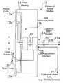
- FIG. 14is a block diagram of a modular power module housing having one or more enhanced inverter modules, a central interface, and connectable to one or more local or remote monitoring or control devices;
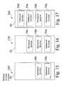
- FIG. 15is a block diagram of a modular power module housing having two sub-modules installed
- FIG. 16is a block diagram of a modular power module housing having three sub-modules installed
- FIG. 17is a block diagram of a modular power module housing having a four sub-module installed
- FIG. 18is a simplified schematic circuit diagram of an exemplary power section for an enhanced inverter module
- FIG. 19shows resultant output power signal properties for active elimination of harmonics by inverter signal modification using sine-weighted pulses
- FIG. 20is a schematic circuit diagram of an exemplary self-power section of a DMPPT module
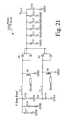
- FIG. 21is a schematic circuit diagram of an exemplary boost circuit for a DMPPT module
- FIG. 22is a schematic circuit diagram of an exemplary current sensor for a DMPPT module
- FIG. 23is a schematic circuit diagram of an exemplary voltage sensor for a DMPPT module
- FIG. 24is a schematic circuit diagram of an exemplary output safety switch for a DMPPT module
- FIG. 25is a schematic circuit diagram of an exemplary crowbar circuit for a DMPPT module
- FIG. 26is a schematic block diagram showing microprocessor-based enhancement of an inverter, such as to eliminate one or more levels of harmonics;
- FIG. 27is flowchart of exemplary operation of an enhanced inverter
- FIG. 28is an exemplary user interface for monitoring and/or control of an enhanced power harvesting system comprising power modules having DMPPT modules;
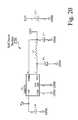
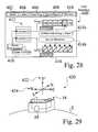
- FIG. 29shows an enhanced power harvesting system located on the Earth, wherein one or more panels within a string have different angles and/or orientations.
- FIG. 1is a schematic view of an exemplary enhanced power module 10 comprising a plurality of power cells 12 , e.g. 12 a - 12 n , such as but not limited to photovoltaic solar cells, fuel cells, and battery cells, connected 16 , 17 to a distributed maximum power point tracking (DMPPT) module 18 .
- FIG. 2is a schematic view of an exemplary enhanced power structure 10 , e.g. an enhanced solar panel 10 , comprising a plurality of solar cells 12 and a distributed maximum power point tracking module 18 .
- FIG. 3is a schematic view 30 of an exemplary photovoltaic solar cell having DC output power connections 17 to a DMPPT module 18 .
- FIG. 1is a schematic view of an exemplary enhanced power module 10 comprising a plurality of power cells 12 , e.g. 12 a - 12 n , such as but not limited to photovoltaic solar cells, fuel cells, and battery cells, connected 16 , 17 to a distributed maximum power point tracking
- FIG. 4is a schematic view of an exemplary solar array 34 comprising a plurality of enhanced solar panels 10 , e.g. 10 a - 10 k , arranged in a plurality of strings 36 , e.g. 36 a - 36 n.
- the exemplary DMPPT module 18 seen in FIG. 1has DC inputs 17 , and a DC output 21 , such as comprising a positive lead 19 a and a negative lead 19 b ,
- the exemplary DMPPT module 18also comprises a communications interface 20 , and means for connection to a temperature sensor 24 , such as responsive to a local panel temperature 23 .
- DMPPT modules 18are preferably locally powered from the solar panel 10 that they are attached to, wherein each DMPPT module 18 draws its operating power from it's respective panel 10 that it is connected to, such as to reduce wiring and to improve efficiency.
- DMPPT modules 18are currently implemented for both new panels 10 , i.e. at the point of manufacture, and for existing systems, wherein the DMPPT modules 18 may be retrofitted to existing panels 10 .
- the external DC connection 21comprising leads 19 a , 19 b , is similar to the input DC connection 17 , such as provided by an existing conventional panel. Therefore, wiring for the DMPPT modules is similar to conventional solar panels, which minimizes the learning curve for installation personnel.
- the communications link 22 shown in FIG. 1may be a wired connection or a wireless connection, such as to provide flexibility in design and installation.
- the DMPPT module 18can communicate via a wireless network, or through a wired connection, e.g. single twisted pair standard RS485 cable.
- Some embodiments of either the wired or wireless style DMPPT modulesfeature a self-discovery function, such that when a new DMPPT module 18 is added to a system 40 ( FIGS. 5 , 6 , 14 ), the system server 153 ( FIG. 14 ) discovers the new module 18 over the communications link 22 , and adds the new module 18 and associated panel 10 to the system 40 .
- wireless style DMPPT modules 18feature a self-healing function, wherein a DMPPT module 18 having a wireless communication link 22 also has the ability to bypass non-functioning devices or branches.
- a DMPPT Module 18is broken or removed, such as by a thief, in a wireless system 40 , everything continues to function.
- the system 40sees the “broken” device 18 , and continues normal communications with the other DMPPT modules 18 .
- solar cells 12are typically matched to make efficient solar panels, and solar panels are typically matched to make efficient solar arrays.
- the output of a solar array having a plurality of conventional solar panels, i.e. without DMPPT modules 18can never match the sum of the maximum power of the conventional solar panels, and the conventional panels can never match the sum of the maximum power of the solar cells 12 .
- environmental conditionse.g. such as but not limited to the time of day, season, weather, location, panel positioning, panel age, and/or panel condition, further degrade the short-term and/or long term efficiency of such systems.
- FIG. 5is a schematic block diagram of an exemplary solar panel system 40 , e.g. 40 a , having a plurality of strings 36 , e.g. 36 a - 36 n , of enhanced solar panels 10 , e.g. 10 a - 10 k , routed through a combiner box 48 and controlled through a modular power module housing 50 having one or more enhanced inverter power modules 54 , e.g. 54 a - 54 j .
- FIG. 6is a schematic block diagram 60 of an alternate exemplary solar panel system is 40 b having a plurality of strings 36 , e.g.
- FIG. 7is a block diagram of an exemplary distributed MPPT circuit 70 for a distributed maximum power point tracker (DMPPT) module 18 , which typically comprises an integrated or retrofitted module 18 for each enhanced solar panel 18 .
- DMPPT modules 18 associated with the enhanced solar panels 10overcome several problems inherent with conventional solar panels and the harvesting of power.
- An input filter 74is preferably attached to the input 72 of the DMPPT module 18 , to help reduce EMI/RFI, as well as to supply protection from surges, etc. on the input side. This also helps in impedance matching between the solar panel 10 and the DMPPT module 18 , such as to improve MPPT tracking.
- the exemplary DMPPT module 18 shown in FIG. 7preferably comprises one or more boost inductors 76 , such as a dual inductively-coupled link inductor 76 to boost the efficiency of the DC-DC conversion stage.
- boost inductors 76such as a dual inductively-coupled link inductor 76 to boost the efficiency of the DC-DC conversion stage.
- small inductor units 76cost less and weigh less than a single inductor design, and there is less chance for core saturation.
- Another benefit of this designis the increased compensation factor. This allows a more stable distributed DC Bus 42 , 52 to be produced, with less requirements for DC-ripple and output filtering 86 .
- Some DMPPT embodiments 18use a multi-phase approach, wherein the controller 80 can reduce the current flow through the power switch 78 , thus increasing efficiency and reducing the heat dissipation load. This also allows the DMPPT 18 to improve power harvesting of the solar panels 10 .
- the controller 80controls the switching of these power devices 78 in a modified spread-spectrum switching scheme, to minimize EMI/RFI radiation of the modules 18 .
- Low loss switching devices 78are used to improve overall efficiency.
- these switching devices 78comprise transistors, FETs, MOSFETs, IGBTs, or any other power-switching device 78 that meets the design criteria.
- Two diodestypically provide rectification 84 for the DMPPT modules 18 , thus reducing the power dissipation and providing a plurality of paths for the power flow.
- the rectification diodes 84also effectively isolate each DMPPT module 18 and associated solar panel 18 from the system array 30 , in case of total panel failure. Even if a DMPPT module 18 fails, this isolation still exists, if it was not the diodes 84 or the output filter 86 that failed. This increases the reliability of the system 40 as a whole.
- a filter 86is preferably attached to the output of the DMPPT modules 18 , to help reduce EMI/RFI, and to provide protection, e.g. from surges, on the output side 90 .
- the output filter 86also helps to stabilize the distributed DC bus 42 , 52 that feeds the solar inverter(s) 54 .
- the controlled production of DC output voltage at the DMPPT modules 18reduces power transmission losses from the array 36 to the inverter(s) 54 .
- the inverters 54run at better efficiency with a stable DC Distributed Bus 42 , 52 . While other conventional inverters experience better efficiency with a higher DC Bus input, as long as it is within the design specifications, the DMPPT module 18 may preferably boost the distributed DC voltage from the array 36 , to maximize this benefit.
- FIG. 8 and FIG. 9show typical Current-Voltage (IV) curves of photovoltaic solar panels. These demonstrate how the voltage moves over a wider range than the current with temperature and solar radiation. The maximum power point for one or more panels moves during the day, and each panel experiences different environmental conditions, even within the same system.
- the distributed maximum power point tracking modules 18 and associated inverter system 40provide several means to maximize the power output over a wide range of such conditions.
- the panel temperature 23( FIG. 1 ) is monitored and reported back to a server, such as an embedded server 153 associated with the inverter housing 50 , or to a server 55 associated with a particular inverter 54 .
- This temperature valueis also used as an input to the multi-level MPPT controller 80 ( FIG. 7 ).
- An op-ampmay preferably be used to scale this value to be read by the controller 80 , and is used as another control input to the controller 80 of the DMPPT module 18 .
- a lead wire and temperature sensor 24exit from the DMPPT Module 18 and attach to the panel 18 .
- a temperature sensor 124is collocated with the DMPPT module 18 , such as inside a panel junction box.
- the embedded server 153may preferably supply an ambient temperature, such as taken outside of the inverter cabinet 54 , or outside a web server box, such as if another inverter is used at the site.
- FIG. 10is time chart 112 showing operation states of the DMPPT 18 , indicating DMPPT input voltage 102 i , and output voltage 102 o for an enhanced power module 10 having a DMPPT module 18 .
- FIG. 11is a flowchart of an exemplary process 122 for operation of an enhanced power module having a DMPPT module 18 .
- the systembehaves like a conventional solar panel array structure.
- a threshold voltage 116FIG. 10
- the DMPPT Module 18automatically wakes up 126 ( FIG. 11 ), and starts performing the necessary checks 128 , 130 , before switching over to RUN Mode 132 .
- the DMPPT 18starts boosting the voltage 102 from the panel 18 to the common distribution bus 52 feeding the solar inverters 54 . This wait is necessary to prevent the loss of control power from the controller circuit 70 ( FIG. 7 ) when switching begins.
- the systemtracks the maximum power point of the solar panel 18 , and boosts the voltage out to the distributed DC Bus 52 feeding the solar inverter(s) 54 .
- the system 40 as a wholeoperates longer before shutting down at the end of a power generation period 118 , e.g. such as at sunset, dusk or evening 119 for externally mounted solar panels 18 . Since the function of maximum power point tracking (MPPT) is performed at the panel level, several other issues associated with solar panels 10 are addressed as well.
- MPPTmaximum power point tracking
- DMPPT units 18problems with mismatched or different manufacturers can be eliminated with the DMPPT units 18 .
- solar panels 10 on different planes and orientationscan be combined into the same system, without any de-rating or loss of harvest from the array 34 .
- the overall efficiency of the arrayis increased, because the MPPT is done on a per panel basis, and not on the average of the entire system.
- string mismatchesare not an issue, due to the active nature of the DMPPT Modules 18 . Conduction losses are reduced, thus allowing more energy to be harvested and transmitted to the inverter 54 for grid conversion.
- the overall efficiency of the array 34is increased, because the panel output is processed, monitored, and controlled on a per panel basis, and not based upon the average of the entire string 36 or array 34 .
- Safety featuresare built into the design for fire safety, monitoring, and several other future applications.
- the DMPPT Module 18addresses many of the current limitations of solar power, such as by providing longer harvest times with panel-level DMPPT modules 18 , by providing “Early-On” and “Late-Off” for extended harvest times. Since the output from the solar panels 10 is boosted, the usable power is converted by the inverter 54 , because the striking voltage is reached sooner and can be held longer, thereby resulting in an increase in harvestable power from each of the solar panels 10 .
- DMPPT modules 18may preferably be reprogrammable or updatable, such as over the communications link 22 , wherein different algorithms may be sent and stored within the DMPPT controllers 80 , such as for modifying start up, operation, safety and shutdown operations.
- DMPPT modules 18also help to reduce the effects of partial shading on solar arrays 34 .
- partial shading of a single cell 12causes the entire panel and string in which it is connected to reduce power output, and also increases loses due to string mismatch, by lowering the MPPT point for an entire solar array.
- the DMPPT modules 18can controllably compensate for partial shading at the panel level, to boost the DC output signal 102 o.
- Test PlatformA test platform was installed to test the benefits and operation of the DMPPT modules 18 .
- the test bedutilized forty-eight solar panels 10 , rated at 170 watts, connected in six strings of eight 170-watt panels each.
- FIG. 12is a schematic layout view 140 of the exemplary test bed solar array 34 comprising a plurality of solar panels 10 , wherein a portion of the panels in one or more strings further comprise DMPPT modules 18 .
- a first group 142 acomprising three strings 36 a , 36 b and 36 c having different sample orientations across the array 34 included DMPPT modules 18
- a second group 142 bcomprising three strings 36 d , 36 e and 36 f having different sample orientations across the array 34 , did not include DMPPT modules 18 .
- the systemwas connected to two identical conventional solar inverters 144 , e.g. 144 a , 144 b for connection to a public AC grid, wherein the first string group 142 b was fed into the first conventional inverter 144 a , and the second string group 142 b was fed into the second conventional inverter 144 b .
- each of the conventional solar inverters 144 a , 144 bwas rated at 4,080 Watts Peak DC.
- FIG. 13shows the relative proportion and size of an exemplary solar array having a capacity of approximately 170W, comprising a plurality of enhanced solar panels, wherein a portion of the panels in one or more strings further comprise DMPPT modules 18 .
- the panels on the test bedare laid out to give a fair representation of solar illumination.
- One half of the panelsare modified with the DMPPT modules 18 , while the other half of the panels are left unmodified, i.e. standard solar panels.
- Each setfeeds into a similar sized solar inverter from the same manufacturer. Data is to be gathered over a period of time to evaluate specific design parameters for the DMPPT modules 18 . Since the strings 36 are set adjacent to each other, shading can be introduced upon the system, such as by using cardboard cutouts and sliding them over the top the solar panels 10 .
- FIG. 14is a block diagram of an exemplary system 40 comprising a modular power inverter housing 50 housing having one or more enhanced inverter modules 54 , e.g. 54 a - 54 j , a central interface 152 , a database 154 , and connectable 155 to one or more local or remote monitoring or control devices 156 , 160 , such as for interaction with a user USR.
- a modular power inverter housing 50having one or more enhanced inverter modules 54 , e.g. 54 a - 54 j , a central interface 152 , a database 154 , and connectable 155 to one or more local or remote monitoring or control devices 156 , 160 , such as for interaction with a user USR.
- the modular power inverter housing 50is powered by the AC bus 56 , e.g. such as by the AC grid 58 , wherein the housing 50 may be powered by a public AC grid 58 even when the power array(s) 34 are down.
- the modular power inverter housing 50is powered by the DC bus 42 , 52 e.g. such as by the solar arrays(s) 34 , wherein the housing 50 may be powered off-grid, even when the AC grid 58 is down.
- the modular power inverter housing 50is powered either off-grid 42 , 52 or on-grid 58 , such as depending on available power.
- a central monitoring and control interface 152interacts with each of the inverters 154 , e.g. the enhanced inverters 54 a - 54 j .
- Each of the enhanced inverters 54preferably comprise a dedicated server 55 ( FIG. 5 , FIG. 6 ), e.g. an embedded web server 55 , or may communicate with a system server 153 , e.g. an embedded system server 153 , associated with the inverter housing 50 .
- the data collected from the power panels 10can be displayed in near real-time, such as through a local device 156 or remote device 160 , e.g. over a network 158 , such as but not limited to a local area network (LAN) a wide area network (WAN), or the Internet.
- This collected datacan also be sent, such as through a server 153 , and logged into a database 154 .
- the exemplary system 40 seen in FIG. 14may therefore preferably provide detailed trending analysis and/or performance tracking over the lifetime of the system.
- the system server 153e.g. an embedded web server 153 , typically gathers information and provides presetting of controls for the entire system 40 , right down to the individual panels 10 , through communication links 22 to panel DMPPT modules 18 .
- the DMPPT module controller 80( FIG. 7 ), e.g. such as comprising a digital signal processor 80 , typically outputs data in a slave mode, such as by reporting data back to an associated embedded server 54 when requested, through one of several means, e.g. such as but not limited to wired or wireless transmission 22 .
- the controller 80also typically accepts measured parameters from the embedded controller 54 pertaining to the local ambient temperature 25 ( FIG. 1 ) and the solar insolation, i.e. the intensity of incident solar radiation These parameters, along with the data collected at the panel 10 , provide control inputs to the program performing the MPPT function on a distributed, i.e. local panel, level.
- the communication links 22 between the DMPPTs 18 and the embedded server(s) 153 , 55comprise either a multi-drop single twisted pair RS-485 communications line 22 , or a wireless radio link 22 .
- the use of wireless communication links 22may be preferred, such as to reduce the wiring cost, thereby reducing the overall cost of the system 40 .
- the protocol used for the communication linksis ModBus, such as RTU RS485 for the wired system, or a wireless tree mesh system with self-healing/discovery capabilities for wireless communication links 22 .
- ModBus protocolsare preferably designed for harsh environments, minimizing or eliminating lost packets of data.
- All distributed datais gathered and passed 22 , e.g. via the RS-485 ModBus links 22 , and then the embedded server 54 at the inverter cabinet 50 formats this into a viewable web page 157 ( FIG. 14 ) for the user USR.
- This collected datacan also be streamed out to another server, e.g. 156 , 160 for data logging and trending applications.
- the heartbeat signalrides on the universal broadcast address, and this synchronizes all of the panels 10 within a few microseconds of each other for their operation.
- Another defined addressbroadcasts the ambient temperature and solar insolation from the server 153 to each of the DMPPT Modules 18 . If communications are lost, or if a “Fire” signal is broadcasted, then the DMPPT Modules 18 automatically shut down, to remove high voltage from their input 72 and output 90 .
- FIG. 15is a block diagram of a modular inverter housing 50 , such as a Model No. ASPM-2-70KW, available through Accurate Solar Systems, Inc. of Menlo Park Calif., having two 35 KW enhanced inverters 54 installed, such as a Model No. ASPM-1-35KW, available through Accurate Solar Systems, Inc. of Menlo Park Calif., having a total rating of 70 KW.
- FIG. 16is a block diagram of a modular inverter housing 50 having three 35 KW enhanced inverters 54 installed, e.g. Model No. ASPM-1-35KW, rated for 105 KW.
- FIG. 17is a block diagram of a modular inverter housing 50 housing having four 35 KW enhanced inverters 54 installed, e.g. Model No. ASPM-1-35KW, rated for 140 KW. While the exemplary enhanced inverters 54 described above are rated at 35 KW each, some alternate embodiments of the enhanced inverters are rated 4 kilowatts each, wherein the system 40 can operate even closer throughout the day.
- the modular inverter housing 50may preferably house a plurality of inverters 54 , to reduce cost, increase efficiency, and improve performance of the system 40 .
- a modular enhanced inverter 54such as but not limited to a 35 kW inverter 54
- a system 40such as for a 35kW system, a 70 kW system 40 , a 105 kW system 40 , or a 140 kW system 40 , which may be housed in one or more types of modular inverter housings 50 .
- Each cabinet 50typically comprises associated transformers, output circuitry, input circuitry, and communications 151 with the embedded web server 153 .
- the smallest current cabinet 50houses a single 35 kW module 54 .
- the next stepis a larger cabinet 50 that houses between two and four of 35 kW enhanced inverter modules, depending on the power required.
- the modular inverter housing systems 50such as seen in FIG. 15 , FIG. 16 and FIG. 17 , if an enhanced inverter 54 goes down, the others continue to deliver power to the AC bus 58 . Therefore, a single fault will not bring the entire system 40 down.
- the enhanced inverter units 54communicate with each other, such as through the embedded web server 153 .
- one of the enhanced inverters 54initially comes on as the system 40 starts up, such as to increase efficiency. As the available power increases, the next enhanced inverter unit 54 is signaled to come online, and so on, such that the system 40 operates at near peak efficiency for as much time as possible, thereby providing more system up time in larger systems. Therefore, in some system embodiments 40 , the use of multiple enhanced modules 54 wastes less energy, as the system 40 only turns on inverters 54 that can be supported by the array 34 .
- each of the enhanced inverter modules 54may preferably be hot swappable.
- the system 40may preferably provide a near real-time view of the current status of the system 40 as a whole. If a problem occurs, then the operator USR is notified by various means, e.g. such as through the user interface 157 .
- the enhanced power inverter system 40may preferably provide the status and performance for each individual panel 10 and string 36 , such that troubleshooting and maintenance is readily performed.
- FIG. 18is a simplified schematic circuit diagram of an exemplary power section 180 for an enhanced inverter module 54 , wherein the enhanced inverter 54 uses a three-phase half bridge IGBT driven power stage, such as provided with IGBTs 192 , driver cards 188 , and fiber optic links 190 .
- PWMpulse width modulation
- FIG. 19shows a resultant output power signal pulse train 200 , based upon active elimination of harmonics by an enhanced inverter module 54 , wherein the power signal is processed using sine weighted pulses.
- PWMpulse width modulation
- some of the edges, e.g. 204 , 206are dynamically linked to other edges in the firing sequence. This has the benefit of simplifying the overall inverter 54 , as well as actively eliminating all third harmonics.
- the enhanced inverter system 54reduces or eliminates harmonics, by controlling where the rising edges 204 and falling edges 206 of the pulse train 200 occur.
- This switching scheme 200allows a relatively simple filter 356 ( FIG. 26 ) to be used, which reduces weight and cost, and improves efficiency.
- the cutoff point for the filter 356is preferably designed for the nineteenth harmonic, thus improving vastly over conventional pulse width modulation methods. For example, for an enhanced 35 kW inverter design, the power savings from switching alone ranges from about 650 Watts to 1 kW of power.
- H03(cos (p1s*3*pi/180) ⁇ cos (p1e*3*pi/180)+cos (p2s*3*pi/180) ⁇ cos (p2e*3*pi/180)+cos (p3s*3*pi/180) ⁇ cos (p3e*3*pi/180)+cos (p4s*3*pi/180) ⁇ cos (p4e*3*pi/180)+cos (p5s*3*pi/180) ⁇ cos (p5e*3*pi/180)+cos (p6s*3*pi/180) ⁇ cos (p6e*3*pi/180)+cos (p7s*3*pi/180) ⁇ cos (p7e*3*pi/180)+0)/(a01*3); where “a01” is the
- a microprocessor 352( FIG. 26 ), such as located at a server 153 embedded within the inverter housing 50 , generates a calculated smart switching pulse train signal 200 , such as shown above.
- the calculated smart switching pulse train signal 200is then passed 366 ( FIG. 27 ) to the driver cards or boards 188 , such as through fiber optic links 190 or via copper wire 190 .
- the driver boards 188then convert these digital pulses 202 ( FIG. 19 ), e.g. 202 a - 202 g , into power driving signals for the IGBTs 192 .
- the IGBTs 192controllably follow the turn-on pulses 204 and turn-off pulses 206 of the original smart switching pulse train signal 200 , thus switching the high DC Bus voltage.
- This switching poweris then transformed to the AC grid voltage 58 by a transformer 355 ( FIG. 26 ) and a relatively small filter 356 ( FIG. 26 ).
- the resultant output sine waveis very low in distortion.
- the use of smart switching 200 inputs to the enhanced inverters 54therefore reduces power loss, reduces harmonics, reduces filter requirements, and reduces cost.
- FIG. 20is a schematic circuit diagram of an exemplary self-power section 220 of a DMPPT module 18 , which generates local control voltage for the DMPPT module 18 from the solar panel 10 .
- the system 40when the solar panel 10 begins generating about 4.5 to 6.5 volts DC, there is enough power to start the DMPPT module 18 .
- the system 40as a whole can wake up automatically, off the external AC grid 58 .
- the user USRis able to observe this wake up phenomena as the sun S rises in the morning, and as it sets in the evening, when the DMPPT modules 18 shut down for the night.
- FIG. 21is a schematic circuit diagram of an exemplary boost circuit 250 for a DMPPT module 10 .
- FIG. 22is a schematic circuit diagram of an exemplary current sensor 270 for a DMPPT module 18 , such as implemented by a V/I monitor 82 ( FIG. 7 ) and associated hardware, e.g. a current loop 83 ( FIG. 7 ).
- FIG. 23is a schematic circuit diagram of an exemplary voltage sensor 290 for a DMPPT module 18 .
- the output voltage and currentare reported back to the embedded server 153 at the inverter cabinet 50 , while used locally by the DMPPT controller 80 ( FIG. 7 ) to provide stable regulated output 90 for the DC distribution bus 42 , 52 ( FIG. 5 , FIG. 6 ).
- the input voltage and currentare used by the on-board controller 80 , e.g. DSP, as part of the multi-level MPPT program.
- the output voltagealso plays into this control loop.
- a Hall-effect DC/AC current module and a 10 M ohm voltage dividing resistor networktransforms these signals to an op-amp for scaling, and are then processed by the controller 80 , e.g. DSP 80 . This forms the basis of a per panel monitoring system.
- FIG. 24is a schematic circuit diagram of an exemplary output safety switch 310 for a DMPPT module 18 .
- FIG. 25is a schematic circuit diagram of an exemplary crowbar circuit 330 for a DMPPT module 18 .
- the enhanced solar panel 10such as seen in FIG. 1 , preferably provides to survivability from an output short circuit.
- an input crowbar circuit 96triggered by the microprocessor 80 , is placed across the incoming power leads from the panel 10 .
- the input crowbar circuit 96is triggered, thereby shorting out the solar panel 18 .
- An output crowbar circuit 98may also preferably be provided, such as to charge down capacitors when the unit is shut down.
- the crowbar circuits 96 , 98may be activated for a wide variety of reasons, such as for emergencies, installation, or maintenance. For example, during installation of the enhanced panels 10 , the associated DMMPT modules 18 prevent high voltage from being transmitted to the output terminals 19 a , 19 b ( FIG. 1 ), until the panel is fully installed into the system 40 . As well, if maintenance functions need to be performed near or on one or more panels 10 , one or more of the solar panels 10 can be turned off, such as by triggering the crowbar circuits 96 , 98 through the DMPPT controllers 80 .
- the crowbar circuits 96 , 98conduct and hold the solar panel 18 in a short-circuit condition until the voltage or current falls below the device's threshold level.
- the currentis typically required to be interrupted. This can typically be done either by manually breaking the circuit, or by waiting until the sunlight fades in late evening. This means that the system automatically resets its DMPPTs 18 during a period of darkness, e.g. the night.
- one of the most cost effective crowbar circuitscomprises a silicon controlled rectifier (SCR) 330 .
- SCRsilicon controlled rectifier
- the DMPPT system 18automatically resets itself during the night, thus allowing for the completion of the work.
- the system 40can operate in one of two modes. In a first mode, such as when communications 22 are present with the host 50 , the host 50 can instruct the DMPPT devices 18 to shut down, thus allowing another period of safe work, e.g. on the roof. In a second mode, such as when there are no communications 22 with the host 50 , the
- DMPPT module 18may preferably fire, i.e. activate, the crowbar device(s) 96 , 98 . To prevent unnecessary shutdowns, this non-communication method may preferably only occur if a status bit has been saved, e.g. in EEPROM memory at the module 18 , indicating a fire or maintenance shutdown.
- the current crowbar circuit 330 implemented for the DMPPT Module 18is an SCR with its associated firing circuitry.
- the main control softwaree.g. within the system server 153 , preferably allows for a maintenance or fire shut down of the solar array system. This operates on a panel per panel basis, thus providing a safe solar array shutdown.
- the host system housing 50can display the current array DC voltage, to indicate when it is safe to enter the roof area.
- the host system housing 50may preferably be tied into the fire alarm system of the building, or may be controlled by a manual safety switch located by the host system itself. This addition to the DMPPT Modules 18 therefore enhances overall system performance, and improves safety for personnel.
- FIG. 26is a schematic block diagram 350 showing microprocessor-based pulse width modulation 354 of an enhanced inverter 54 , such as to eliminate one or more levels of harmonics.
- FIG. 27is flowchart of an exemplary PWM harmonic reduction process 360 for an enhanced inverter 54 .
- a microprocessor 352may preferably be used to provide a driving signal 354 to each of the enhanced inverters 54 .
- the DC power 42 , 52 from the panels 10 , or the AC bus power 58may be used to turn on 364 the power to the inverter transistors 192 ( FIG.
- a special signal 354( FIG. 26 ), which may preferably comprise a smart switching pulse train 200 ( FIG. 19 ), e.g. such as but not limited to switching at 1.68 KHz, is sent from the microprocessor 352 at the embedded server 153 ( FIG. 14 ), to switch the DC bus through the driver cards 188 ( FIG. 18 ) and provide active elimination of one or more harmonics, such as to controllably reduce or eliminate the harmonics from the DC signal, e.g. third harmonics 3, 9, 15, etc.
- the AC signal output 368 from the enhanced inverter 54provides increased power over conventional inverter systems.
- each inverter block 54may preferably turn on when needed to increase system efficiency.
- Solid-state inverters 54presently run better once they have more than about 45 percent load.
- a first module 54will turn on to provide power until there is enough power for the second module 54 .
- the second module 54will come on and the two modules 54 , e.g. 54 a and 54 b will share the load (and still above the 45% point) until a third module 54 is needed.
- the sameis true until all four modular inverters 54 are on.
- each modular inverter 54will drop off as necessary, until the system 40 shuts down for the night. This keeps the system 40 running at peak efficiency longer than a single large inverter, thus generating more power for the AC grid 58 .
- the use of smart switching of the inverters 54delivers more power to the grid, since less solar power is converted into heat from the switching of the transistors. Furthermore, since a smaller filter is required (due to harmonic cancellation), there is more power available for pumping to the grid.
- Another benefit of the modular system 40is redundancy. For example, in a system having more than one enhanced inverter 54 , if one enhanced inverter 54 fails for some reason, the entire system 40 does not come down. The system can continue to pump power out to the AC grid 58 with what capacity is left in the system 40 .
- FIG. 28is an exemplary user interface 400 , such as comprising a web page 157 ( FIG. 14 ), for monitoring and/or control of an enhanced power harvesting system 40 comprising enhanced inverters 54 , and power modules 10 having DMPPT modules 18 .
- the exemplary user interface 400 seen in FIG. 28may typically comprise any of system, array and/or component level status 402 , control 404 , logs 406 for one or more panels 10 , system reports 408 , and revenue tracking 410 .
- an exemplary system status screen 412is seen in FIG. 28 , such as to indicate current operating status of different strings 36 of solar panels 10 .
- a first string 36 of panelscomprises six panels 10 , wherein panels 1 - 4 and 6 in the string are indicated 414 a as being online and OK, while the fifth panel 10 in the first string is indicated 414 a as being a problem and is currently taken offline.
- a second string 36 of panelscomprises six panels 10 , wherein panels 1 - 6 in the second string are indicated 414 b as being shutdown for service, such as controlled 416 through the user interface 400 .
- the user interface 400may typically be accessed through a wide variety of terminals, such as directly through an embedded server 153 , locally through a connected terminal 156 , or at another terminal 160 , such as accessible through a network 158 .
- the system 40may provide other means for alerts, status, and/or control, such as but not limited to network communication 155 to a wireless device 160 , e.g.
- a laptop computersuch as but not limited to a laptop computer, a cell phone, a pager, and/or a network enabled cellular phone or PDA.
- each of the panels 10preferably comprises DMPPT functionality 18 , wherein the DMPPTs provide monitoring at the panel level, the system 40 is readily informed, such as over the communication links 22 between the DMPPTs 18 and the invertors 54 or housing 50 , of the operating status of each panel 10 in any size of array 34 .
- the DMPPTs 18similarly provide troubleshooting and diagnostics at the panel level. For example, if there is a problem with one or more panels 10 , such as not working, shut down locally by a controller 80 , dirty, or shaded, the system 40 will be informed over the communication links 22 of any and all panel-level information, and can alert the user USR. All information from the panels 10 is typically logged into a database 154 , where performance, history trends, and predications of future performance can be calculated.
- the database 154may preferably be connectable through a network 158 , such as the Internet, i.e. the World Wide Web, wherein viewing, and even control and/or maintenance, may be done through a web browser at a remote terminal 160 .
- each enhanced panel 10is connected to an associated DMPPT module 18 , is problems can be identified and pinpointed for both broken and sub-performing panels 10 , wherein such panels 10 may readily be found and replaced, i.e. the system 40 identifies the exact panel(s) with a problem, thus significantly reducing the time required for repairs.
- FIG. 29shows an enhanced power harvesting system 40 located on the Earth E, wherein one or more panels 10 within a string 36 have different angles (0, 45, 90) or orientations (E, W, N, S).
- Conventional solar panels systemsrequire solar panels having different angles of tilt to be serviced by different inverters.
- enhanced panels 10 having different tilt angles 422can be fed into the same inverter, e.g. an enhanced inverter 54 .
- the enhanced system 40therefore allows panels to be mixed, such by varying tilt 422 , from flat (0 degrees) through 90 degrees, and/or by varying directional orientation 424 , by mixing East, West, South and/or North facing panels 10 .
- strings 36 having different lengths of enhanced panels 10may be fed into the same inverter, e.g. an enhanced inverter 54 or even a conventional inverter.
- the DMPPT modulescan adjust the output of the remaining panels 10 in a string 36 to allow this “incorrect” string size to function in the system 40 , without adverse affects.
- DMPPT modules 40allows different size panels or different manufacturers to co-exist in the same array 34 . Therefore, instead of having to buy all of the panels from a single manufacturer to reduce mismatch problems, the DMPPT allows the use of various panels and even different wattages within the same system 40 .
- Such versatilityprovides significant architectural freedom in panel placement and design, wherein solar panels equipped with an associated DMPPT module 10 allow unique layouts to accommodate different architectural features on any building or facility.
- DMPPT modules 40addresses panel and string mismatch losses.
- no two panels 10are alike, and often are specified with a plus or minus 5 percent rating.
- conventional solar panel strings 36operate only as well as the weakest panel 10 in the string
- the DMPPT modules 18can adjust the output of the panels 10 to boost their output.
- the DMPPT modules 18 for a string 34such as controlled by the server over the communications links 22 , can boost the power as needed to reduce or even eliminate string mismatch losses.
- the software for the DMPPT modules 18can be broken down into various sections as most are interrupt driven. When the modules 18 wake up in the morning, they each perform a routine check to ensure that everything is functioning properly.
- the modules 18preferably check the status of a fire alarm flag, which is stored in EEPROM inside the microprocessor/controller 80 of the DMPPT Module.
- the microprocessor currently implemented for the controller 80includes FLASH, EEPROM, and SRAM memories on the chip.
- the enhanced inverters, as well as the DMPPT modulesmay readily be adapted for different means of power generation, such as but not limited to fuel cells, wind power, Hydro, Batteries, Biomass, and Solar power.
- the inverterscan operate at 50 Hz, 60Hz, or 400 Hz to cover a vast range of applications.
- the systemcan also be designed for on-grid or off-grid applications.
- the structures and methods disclosed hereinare implemented for the fabrication of solar panel system, the structures and methods may alternately be used for a wide variety of power generation and harvesting embodiments, such as for fuel cells or batteries, over a wide variety of processing and operating conditions.
- server 153within the modular inverter housing 50
- other embodimentsmay comprise dedicated servers 55 within each of the enhanced inverters 54 , which may also be in combination with a housing server 153 .
- the exemplary DMPPT modules 18 disclosed hereinare located at each of the panels, dedicated DMPPT modules can alternately be located at different points, such as ganged together locally near the panel strings 36 . In present embodiments, however, the DMPPT modules 18 disclosed herein are located at each of the panels 10 , such as to provide increased safety, since the crowbar circuitry 96 , 98 is located at the panel, and upon activation, no high voltage extends from the panels on the output connections 21 .
Landscapes
- Engineering & Computer Science (AREA)
- Power Engineering (AREA)
- Inverter Devices (AREA)
- Life Sciences & Earth Sciences (AREA)
- Sustainable Development (AREA)
- Sustainable Energy (AREA)
- Supply And Distribution Of Alternating Current (AREA)
- Control Of Electrical Variables (AREA)
- Photovoltaic Devices (AREA)
- Direct Current Feeding And Distribution (AREA)
Abstract
Description
H03=(cos (p1s*3*pi/180)−cos (p1e*3*pi/180)+cos (p2s*3*pi/180)−cos (p2e*3*pi/180)+cos (p3s*3*pi/180)−cos (p3e*3*pi/180)+cos (p4s*3*pi/180)−cos (p4e*3*pi/180)+cos (p5s*3*pi/180)−cos (p5e*3*pi/180)+cos (p6s*3*pi/180)−cos (p6e*3*pi/180)+cos (p7s*3*pi/180)−cos (p7e*3*pi/180)+0)/(a01*3);
where “a01” is the power of the fundamental waveform, p stands for pulse, the number next to p indicates the number of the pulse, s stands for the start of the pulse, and e stands for the end of the pulse, e.g. p1s indicates the start of the first pulse, and p1e indicates the end of the first pulse. Also, the first three pulses and the ending fifth pulse are linked to the others, to eliminate the third harmonics.
Claims (31)
Priority Applications (11)
| Application Number | Priority Date | Filing Date | Title |
|---|---|---|---|
| US13/250,887US8427009B2 (en) | 2007-03-27 | 2011-09-30 | Distributed maximum power point tracking system, structure and process |
| US13/615,014US9196770B2 (en) | 2007-03-27 | 2012-09-13 | Pole-mounted power generation systems, structures and processes |
| US13/866,962US9812859B2 (en) | 2007-03-27 | 2013-04-19 | Distributed maximum power point tracking system, structure and process |
| US14/949,611US20160079760A1 (en) | 2009-08-14 | 2015-11-23 | Pole-mounted power generation systems, structures and processes |
| US15/275,272US10020657B2 (en) | 2007-03-27 | 2016-09-23 | Pole-mounted power generation systems, structures and processes |
| US15/722,310US10615594B2 (en) | 2007-03-27 | 2017-10-02 | Distributed maximum power point tracking system, structure and process |
| US16/030,758US20180323617A1 (en) | 2007-03-27 | 2018-07-09 | Pole-mounted power generation systems, structures and processes |
| US16/840,956US11557683B2 (en) | 2007-03-27 | 2020-04-06 | Distributed maximum power point tracking system, structure and process |
| US16/904,894US12074229B2 (en) | 2007-03-27 | 2020-06-18 | Distributed maximum power point tracking system, structure and process |
| US17/994,478US11967654B2 (en) | 2007-03-27 | 2022-11-28 | Distributed maximum power point tracking system, structure and process |
| US18/615,127US20240313131A1 (en) | 2007-03-27 | 2024-03-25 | Distributed Maximum Power Point Tracking System, Structure and Process |
Applications Claiming Priority (8)
| Application Number | Priority Date | Filing Date | Title |
|---|---|---|---|
| US90836107P | 2007-03-27 | 2007-03-27 | |
| US12/056,235US7772716B2 (en) | 2007-03-27 | 2008-03-26 | Distributed maximum power point tracking system, structure and process |
| USPCT/US08/58473 | 2008-03-27 | ||
| PCT/US2008/058473WO2008119034A1 (en) | 2007-03-27 | 2008-03-27 | Distributed maximum power point tracking system, structure and process |
| US12/842,864US8035249B2 (en) | 2007-03-27 | 2010-07-23 | Distributed maximum power point tracking system, structure and process |
| USPCT/US10/45352 | 2010-08-12 | ||
| PCT/US2010/045352WO2011019936A1 (en) | 2009-08-14 | 2010-08-12 | Enhanced solar panels, liquid delivery systems and associated processes for solar energy systems |
| US13/250,887US8427009B2 (en) | 2007-03-27 | 2011-09-30 | Distributed maximum power point tracking system, structure and process |
Related Parent Applications (1)
| Application Number | Title | Priority Date | Filing Date |
|---|---|---|---|
| US12/842,864ContinuationUS8035249B2 (en) | 2007-03-27 | 2010-07-23 | Distributed maximum power point tracking system, structure and process |
Related Child Applications (3)
| Application Number | Title | Priority Date | Filing Date |
|---|---|---|---|
| US12/056,235Continuation-In-PartUS7772716B2 (en) | 2007-03-27 | 2008-03-26 | Distributed maximum power point tracking system, structure and process |
| US13/615,014Continuation-In-PartUS9196770B2 (en) | 2007-03-27 | 2012-09-13 | Pole-mounted power generation systems, structures and processes |
| US13/866,962ContinuationUS9812859B2 (en) | 2007-03-27 | 2013-04-19 | Distributed maximum power point tracking system, structure and process |
Publications (2)
| Publication Number | Publication Date |
|---|---|
| US20120032665A1 US20120032665A1 (en) | 2012-02-09 |
| US8427009B2true US8427009B2 (en) | 2013-04-23 |
Family
ID=39789048
Family Applications (9)
| Application Number | Title | Priority Date | Filing Date |
|---|---|---|---|
| US12/056,235ActiveUS7772716B2 (en) | 2007-03-27 | 2008-03-26 | Distributed maximum power point tracking system, structure and process |
| US12/842,864ActiveUS8035249B2 (en) | 2007-03-27 | 2010-07-23 | Distributed maximum power point tracking system, structure and process |
| US13/250,887ActiveUS8427009B2 (en) | 2007-03-27 | 2011-09-30 | Distributed maximum power point tracking system, structure and process |
| US13/866,962Active2031-01-03US9812859B2 (en) | 2007-03-27 | 2013-04-19 | Distributed maximum power point tracking system, structure and process |
| US15/722,310ActiveUS10615594B2 (en) | 2007-03-27 | 2017-10-02 | Distributed maximum power point tracking system, structure and process |
| US16/840,956Active2028-06-05US11557683B2 (en) | 2007-03-27 | 2020-04-06 | Distributed maximum power point tracking system, structure and process |
| US16/904,894Active2030-03-10US12074229B2 (en) | 2007-03-27 | 2020-06-18 | Distributed maximum power point tracking system, structure and process |
| US17/994,478ActiveUS11967654B2 (en) | 2007-03-27 | 2022-11-28 | Distributed maximum power point tracking system, structure and process |
| US18/615,127AbandonedUS20240313131A1 (en) | 2007-03-27 | 2024-03-25 | Distributed Maximum Power Point Tracking System, Structure and Process |
Family Applications Before (2)
| Application Number | Title | Priority Date | Filing Date |
|---|---|---|---|
| US12/056,235ActiveUS7772716B2 (en) | 2007-03-27 | 2008-03-26 | Distributed maximum power point tracking system, structure and process |
| US12/842,864ActiveUS8035249B2 (en) | 2007-03-27 | 2010-07-23 | Distributed maximum power point tracking system, structure and process |
Family Applications After (6)
| Application Number | Title | Priority Date | Filing Date |
|---|---|---|---|
| US13/866,962Active2031-01-03US9812859B2 (en) | 2007-03-27 | 2013-04-19 | Distributed maximum power point tracking system, structure and process |
| US15/722,310ActiveUS10615594B2 (en) | 2007-03-27 | 2017-10-02 | Distributed maximum power point tracking system, structure and process |
| US16/840,956Active2028-06-05US11557683B2 (en) | 2007-03-27 | 2020-04-06 | Distributed maximum power point tracking system, structure and process |
| US16/904,894Active2030-03-10US12074229B2 (en) | 2007-03-27 | 2020-06-18 | Distributed maximum power point tracking system, structure and process |
| US17/994,478ActiveUS11967654B2 (en) | 2007-03-27 | 2022-11-28 | Distributed maximum power point tracking system, structure and process |
| US18/615,127AbandonedUS20240313131A1 (en) | 2007-03-27 | 2024-03-25 | Distributed Maximum Power Point Tracking System, Structure and Process |
Country Status (4)
| Country | Link |
|---|---|
| US (9) | US7772716B2 (en) |
| EP (1) | EP2130286A4 (en) |
| CN (1) | CN101953051B (en) |
| WO (1) | WO2008119034A1 (en) |
Cited By (69)
| Publication number | Priority date | Publication date | Assignee | Title |
|---|---|---|---|---|
| US20130241448A1 (en)* | 2012-03-19 | 2013-09-19 | Sharp Kabushiki Kaisha | Photovoltaic apparatus, maximum power point tracking control method and computer program in the same, and moving body including the same |
| US9293619B2 (en) | 2011-11-20 | 2016-03-22 | Solexel, Inc. | Smart photovoltaic cells and modules |
| US9537445B2 (en) | 2008-12-04 | 2017-01-03 | Solaredge Technologies Ltd. | Testing of a photovoltaic panel |
| US9543889B2 (en) | 2006-12-06 | 2017-01-10 | Solaredge Technologies Ltd. | Distributed power harvesting systems using DC power sources |
| US9639106B2 (en) | 2012-03-05 | 2017-05-02 | Solaredge Technologies Ltd. | Direct current link circuit |
| US9748896B2 (en) | 2009-05-22 | 2017-08-29 | Solaredge Technologies Ltd. | Electrically isolated heat dissipating junction box |
| US9853565B2 (en) | 2012-01-30 | 2017-12-26 | Solaredge Technologies Ltd. | Maximized power in a photovoltaic distributed power system |
| US9853490B2 (en) | 2006-12-06 | 2017-12-26 | Solaredge Technologies Ltd. | Distributed power system using direct current power sources |
| US9853538B2 (en) | 2007-12-04 | 2017-12-26 | Solaredge Technologies Ltd. | Distributed power harvesting systems using DC power sources |
| US9866098B2 (en) | 2011-01-12 | 2018-01-09 | Solaredge Technologies Ltd. | Serially connected inverters |
| US9869701B2 (en) | 2009-05-26 | 2018-01-16 | Solaredge Technologies Ltd. | Theft detection and prevention in a power generation system |
| US9876430B2 (en) | 2008-03-24 | 2018-01-23 | Solaredge Technologies Ltd. | Zero voltage switching |
| US9923516B2 (en) | 2012-01-30 | 2018-03-20 | Solaredge Technologies Ltd. | Photovoltaic panel circuitry |
| US9935458B2 (en) | 2010-12-09 | 2018-04-03 | Solaredge Technologies Ltd. | Disconnection of a string carrying direct current power |
| US9948233B2 (en) | 2006-12-06 | 2018-04-17 | Solaredge Technologies Ltd. | Distributed power harvesting systems using DC power sources |
| US9960731B2 (en) | 2006-12-06 | 2018-05-01 | Solaredge Technologies Ltd. | Pairing of components in a direct current distributed power generation system |
| US9966848B2 (en) | 2009-09-02 | 2018-05-08 | Tigo Energy, Inc. | Systems and methods for enhanced efficiency auxiliary power supply module |
| US9979280B2 (en) | 2007-12-05 | 2018-05-22 | Solaredge Technologies Ltd. | Parallel connected inverters |
| US10063056B2 (en) | 2009-12-29 | 2018-08-28 | Tigo Energy, Inc. | Systems and methods for remote or local shut-off of a photovoltaic system |
| US10061957B2 (en) | 2016-03-03 | 2018-08-28 | Solaredge Technologies Ltd. | Methods for mapping power generation installations |
| US10097007B2 (en) | 2006-12-06 | 2018-10-09 | Solaredge Technologies Ltd. | Method for distributed power harvesting using DC power sources |
| US10116217B2 (en) | 2007-08-06 | 2018-10-30 | Solaredge Technologies Ltd. | Digital average input current control in power converter |
| US10115841B2 (en) | 2012-06-04 | 2018-10-30 | Solaredge Technologies Ltd. | Integrated photovoltaic panel circuitry |
| US10135385B2 (en) | 2010-01-08 | 2018-11-20 | Tigo Energy, Inc. | Identification protocol between a local controller of a solar module and a master controller |
| US10181541B2 (en) | 2011-11-20 | 2019-01-15 | Tesla, Inc. | Smart photovoltaic cells and modules |
| US10187115B2 (en) | 2015-07-13 | 2019-01-22 | Maxim Integrated Products, Inc. | Systems and methods for DC power line communication in a photovoltaic system |
| US10230427B2 (en) | 2015-07-13 | 2019-03-12 | Maxim Integrated Products, Inc. | Systems and methods for DC power line communication in a photovoltaic system |
| US10230310B2 (en) | 2016-04-05 | 2019-03-12 | Solaredge Technologies Ltd | Safety switch for photovoltaic systems |
| US10230245B2 (en) | 2006-12-06 | 2019-03-12 | Solaredge Technologies Ltd | Battery power delivery module |
| US10256770B2 (en) | 2007-11-02 | 2019-04-09 | Tigo Energy, Inc. | System and method for enhanced watch dog in solar panel installations |
| US10270253B2 (en) | 2015-05-14 | 2019-04-23 | Varentec, Inc. | System and method for regulating the reactive power flow of one or more inverters coupled to an electrical grid |
| US10312857B2 (en) | 2009-09-03 | 2019-06-04 | Tigo Energy, Inc. | Systems and methods for an enhanced watchdog in solar module installations |
| US10468878B2 (en) | 2008-05-05 | 2019-11-05 | Solaredge Technologies Ltd. | Direct current power combiner |
| US10599113B2 (en) | 2016-03-03 | 2020-03-24 | Solaredge Technologies Ltd. | Apparatus and method for determining an order of power devices in power generation systems |
| US10608553B2 (en) | 2012-01-30 | 2020-03-31 | Solaredge Technologies Ltd. | Maximizing power in a photovoltaic distributed power system |
| US10615594B2 (en) | 2007-03-27 | 2020-04-07 | Solaredge Technologies Ltd. | Distributed maximum power point tracking system, structure and process |
| US10651647B2 (en) | 2013-03-15 | 2020-05-12 | Solaredge Technologies Ltd. | Bypass mechanism |
| US10673222B2 (en) | 2010-11-09 | 2020-06-02 | Solaredge Technologies Ltd. | Arc detection and prevention in a power generation system |
| US10673229B2 (en) | 2010-11-09 | 2020-06-02 | Solaredge Technologies Ltd. | Arc detection and prevention in a power generation system |
| US10778482B2 (en) | 2019-02-12 | 2020-09-15 | Texas Instruments Incorporated | Bit slicer circuit for S-FSK receiver, integrated circuit, and method associated therewith |
| US10778025B2 (en) | 2013-03-14 | 2020-09-15 | Solaredge Technologies Ltd. | Method and apparatus for storing and depleting energy |
| US10784815B2 (en) | 2013-04-13 | 2020-09-22 | Sigmagen, Inc. | Solar photovoltaic module remote access module switch and real-time temperature monitoring |
| US10797921B2 (en) | 2019-02-12 | 2020-10-06 | Texas Instruments Incorporated | Threshold computation circuit for S-FSK receiver, integrated circuit, and method associated therewith |
| US10931119B2 (en) | 2012-01-11 | 2021-02-23 | Solaredge Technologies Ltd. | Photovoltaic module |
| US10931228B2 (en) | 2010-11-09 | 2021-02-23 | Solaredge Technologies Ftd. | Arc detection and prevention in a power generation system |
| US11018623B2 (en) | 2016-04-05 | 2021-05-25 | Solaredge Technologies Ltd. | Safety switch for photovoltaic systems |
| US11031861B2 (en) | 2006-12-06 | 2021-06-08 | Solaredge Technologies Ltd. | System and method for protection during inverter shutdown in distributed power installations |
| US11081608B2 (en) | 2016-03-03 | 2021-08-03 | Solaredge Technologies Ltd. | Apparatus and method for determining an order of power devices in power generation systems |
| US11177663B2 (en) | 2016-04-05 | 2021-11-16 | Solaredge Technologies Ltd. | Chain of power devices |
| US11190022B2 (en) | 2019-01-09 | 2021-11-30 | Texas Instruments Incorporated | Controller circuit for photovoltaic sub-module |
| US11228278B2 (en) | 2007-11-02 | 2022-01-18 | Tigo Energy, Inc. | System and method for enhanced watch dog in solar panel installations |
| US11264947B2 (en) | 2007-12-05 | 2022-03-01 | Solaredge Technologies Ltd. | Testing of a photovoltaic panel |
| US11296650B2 (en) | 2006-12-06 | 2022-04-05 | Solaredge Technologies Ltd. | System and method for protection during inverter shutdown in distributed power installations |
| US11309832B2 (en) | 2006-12-06 | 2022-04-19 | Solaredge Technologies Ltd. | Distributed power harvesting systems using DC power sources |
| US11342787B2 (en) | 2019-03-20 | 2022-05-24 | Texas Instruments Incorporated | Controller circuit for photovoltaic module |
| US11350186B2 (en) | 2019-03-20 | 2022-05-31 | Texas Instruments Incorporated | Monitoring circuit for photovoltaic module |
| US11451052B2 (en) | 2018-05-04 | 2022-09-20 | Nextracker Llc | Systems and methods of DC power conversion and transmission for solar fields |
| US11569660B2 (en) | 2006-12-06 | 2023-01-31 | Solaredge Technologies Ltd. | Distributed power harvesting systems using DC power sources |
| US11569659B2 (en) | 2006-12-06 | 2023-01-31 | Solaredge Technologies Ltd. | Distributed power harvesting systems using DC power sources |
| US11598652B2 (en) | 2006-12-06 | 2023-03-07 | Solaredge Technologies Ltd. | Monitoring of distributed power harvesting systems using DC power sources |
| US11687112B2 (en) | 2006-12-06 | 2023-06-27 | Solaredge Technologies Ltd. | Distributed power harvesting systems using DC power sources |
| US11728768B2 (en) | 2006-12-06 | 2023-08-15 | Solaredge Technologies Ltd. | Pairing of components in a direct current distributed power generation system |
| US11735910B2 (en) | 2006-12-06 | 2023-08-22 | Solaredge Technologies Ltd. | Distributed power system using direct current power sources |
| US11855231B2 (en) | 2006-12-06 | 2023-12-26 | Solaredge Technologies Ltd. | Distributed power harvesting systems using DC power sources |
| US11881814B2 (en) | 2005-12-05 | 2024-01-23 | Solaredge Technologies Ltd. | Testing of a photovoltaic panel |
| US11888387B2 (en) | 2006-12-06 | 2024-01-30 | Solaredge Technologies Ltd. | Safety mechanisms, wake up and shutdown methods in distributed power installations |
| US12057807B2 (en) | 2016-04-05 | 2024-08-06 | Solaredge Technologies Ltd. | Chain of power devices |
| US12224703B2 (en) | 2020-07-29 | 2025-02-11 | Nextracker Llc | Fixed DC bus and hydrogen generation system |
| US12418177B2 (en) | 2009-10-24 | 2025-09-16 | Solaredge Technologies Ltd. | Distributed power system using direct current power sources |
Families Citing this family (194)
| Publication number | Priority date | Publication date | Assignee | Title |
|---|---|---|---|---|
| US7900361B2 (en)* | 2006-12-06 | 2011-03-08 | Solaredge, Ltd. | Current bypass for distributed power harvesting systems using DC power sources |
| US9196770B2 (en) | 2007-03-27 | 2015-11-24 | Newdoll Enterprises Llc | Pole-mounted power generation systems, structures and processes |
| US20090000654A1 (en) | 2007-05-17 | 2009-01-01 | Larankelo, Inc. | Distributed inverter and intelligent gateway |
| US10468993B2 (en)* | 2007-05-17 | 2019-11-05 | Enphase Energy, Inc. | Inverter for use in photovoltaic module |
| US20090020151A1 (en)* | 2007-07-16 | 2009-01-22 | Pvi Solutions, Inc. | Method and apparatus for converting a direct current to alternating current utilizing a plurality of inverters |
| US9048693B2 (en)* | 2007-09-06 | 2015-06-02 | Enphase Energy, Inc. | Method and apparatus for detecting impairment of a solar array |
| US8397085B2 (en)* | 2007-09-24 | 2013-03-12 | Siemens Industry, Inc. | Master controller containing a control processor configured to receive power cell control information and a host processor configured to receive command and status information |
| WO2009055474A1 (en) | 2007-10-23 | 2009-04-30 | And, Llc | High reliability power systems and solar power converters |
| CA2737134C (en) | 2007-10-15 | 2017-10-10 | Ampt, Llc | Systems for highly efficient solar power |
| US8423308B2 (en)* | 2007-11-01 | 2013-04-16 | Leviton Mfg. Co. | Multi-circuit direct current monitor with Modbus serial output |
| CN105244905B (en) | 2007-12-05 | 2019-05-21 | 太阳能安吉有限公司 | Release mechanism in distributed power device is waken up and method for closing |
| EP2225778B1 (en) | 2007-12-05 | 2019-06-26 | Solaredge Technologies Ltd. | Testing of a photovoltaic panel |
| WO2009073867A1 (en) | 2007-12-05 | 2009-06-11 | Solaredge, Ltd. | Parallel connected inverters |
| US9291696B2 (en) | 2007-12-05 | 2016-03-22 | Solaredge Technologies Ltd. | Photovoltaic system power tracking method |
| US20090188488A1 (en)* | 2008-01-28 | 2009-07-30 | Tilt Solar Llc | Wireless mesh networking of solar tracking devices |
| US8037327B2 (en)* | 2008-03-31 | 2011-10-11 | Agilent Technologies, Inc. | System and method for improving dynamic response in a power supply |
| KR100993108B1 (en)* | 2008-05-30 | 2010-11-08 | 군산대학교산학협력단 | Grid-connected photovoltaic power generation system with improved power quality and power saving |
| US8630098B2 (en) | 2008-06-12 | 2014-01-14 | Solaredge Technologies Ltd. | Switching circuit layout with heatsink |
| US20090315336A1 (en)* | 2008-06-23 | 2009-12-24 | Hudson Worthington Harr | Renewable energy generation system |
| EP2311163A4 (en)* | 2008-07-01 | 2013-08-21 | Satcon Technology Corp | PHOTOVOLTAIC CONTINUOUS / CONTINUOUS MICROCONVERTER |
| US9048353B2 (en) | 2008-07-01 | 2015-06-02 | Perfect Galaxy International Limited | Photovoltaic DC/DC micro-converter |
| EP2299497A4 (en)* | 2008-07-08 | 2014-02-19 | Mitsubishi Electric Corp | DEVICE FOR PRODUCING SOLAR ELECTRICITY |
| US8466581B2 (en)* | 2008-08-01 | 2013-06-18 | Petrasolar, Inc. | System and method for utility pole distributed solar power generation |
| US8273979B2 (en)* | 2008-10-15 | 2012-09-25 | Xandex, Inc. | Time averaged modulated diode apparatus for photovoltaic application |
| US20100116325A1 (en)* | 2008-11-12 | 2010-05-13 | Mehrdad Nikoonahad | High efficiency solar panel and system |
| US8791598B2 (en) | 2008-12-21 | 2014-07-29 | NavSemi Energy Private Ltd. | System and method for selectively controlling a solar panel in segments |
| US20100156188A1 (en)* | 2008-12-24 | 2010-06-24 | Fishman Oleg S | Solar Photovoltaic Power Collection via High Voltage, Direct Current Systems with Conversion and Supply to an Alternating Current Transmission Network |
| US8212408B2 (en)* | 2008-12-24 | 2012-07-03 | Alencon Acquisition Co., Llc. | Collection of electric power from renewable energy sources via high voltage, direct current systems with conversion and supply to an alternating current transmission network |
| FR2941074B1 (en)* | 2009-01-15 | 2011-07-15 | Thierry Noglotte | SYSTEM FOR ACQUIRING PRODUCTION DATA AND ENVIRONMENT OF ENERGY PRODUCTION |
| US8297273B2 (en)* | 2009-02-08 | 2012-10-30 | Atomic Energy Council—Institute of Nuclear Energy Research | Controlling apparatus for a concentration photovoltaic system |
| DE102009009860B4 (en)* | 2009-02-20 | 2010-11-25 | Enwi-Etec Gmbh | Especially pre-assembled photovoltaic system connection cabinet |
| US8076625B2 (en)* | 2009-02-25 | 2011-12-13 | Solfocus, Inc. | Field level tracker controller |
| US20100213761A1 (en)* | 2009-02-25 | 2010-08-26 | Solfocus, Inc. | Field Level Inverter Controller |
| CA2757331A1 (en)* | 2009-04-01 | 2010-10-07 | Nextronex Inc. | A grid tie solar system and a method |
| US20100259225A1 (en)* | 2009-04-10 | 2010-10-14 | Triune Ip Llc | Adaptive Power Control for Energy Harvesting |
| SG175717A1 (en) | 2009-04-17 | 2011-12-29 | Ampt Llc | Methods and apparatus for adaptive operation of solar power systems |
| US8200373B2 (en)* | 2009-04-23 | 2012-06-12 | Pentair Water Pool And Spa, Inc. | Energy production and consumption matching system |
| US8217534B2 (en)* | 2009-05-20 | 2012-07-10 | General Electric Company | Power generator distributed inverter |
| US8303349B2 (en) | 2009-05-22 | 2012-11-06 | Solaredge Technologies Ltd. | Dual compressive connector |
| US8690110B2 (en) | 2009-05-25 | 2014-04-08 | Solaredge Technologies Ltd. | Bracket for connection of a junction box to photovoltaic panels |
| IT1395681B1 (en)* | 2009-05-28 | 2012-10-16 | Beghelli Spa | STRUCTURAL MODULE FOR PHOTOVOLTAIC GENERATION WITH HIGH CONCENTRATION |
| US20100301676A1 (en)* | 2009-05-28 | 2010-12-02 | General Electric Company | Solar power generation system including weatherable units including photovoltaic modules and isolated power converters |
| US8184460B2 (en)* | 2009-05-28 | 2012-05-22 | General Electric Company | Solar inverter and control method |
| US8239149B2 (en)* | 2009-06-25 | 2012-08-07 | Array Power, Inc. | Method for determining the operating condition of a photovoltaic panel |
| AU2010100350B4 (en)* | 2009-07-22 | 2012-02-23 | Deodhar Electro Design Pvt. Ltd | Integrated PV panel |
| CA2758815A1 (en) | 2009-07-23 | 2011-01-27 | Enphase Energy, Inc. | Method and apparatus for detection and control of dc arc faults |
| EP2284973B1 (en)* | 2009-08-06 | 2012-04-25 | SMA Solar Technology AG | Reverse current sensor for solar modules connected in parallel |
| US20160065127A1 (en) | 2009-08-14 | 2016-03-03 | Newdoll Enterprises Llc | Enhanced solar panels, liquid delivery systems and associated processes for solar energy systems |
| EP2464465A4 (en) | 2009-08-14 | 2014-05-07 | Newdoll Entpr Llc | ENHANCED SOLAR PANELS, LIQUID DELIVERY SYSTEMS AND ASSOCIATED METHODS FOR SOLAR ENERGY SYSTEMS |
| US9200818B2 (en) | 2009-08-14 | 2015-12-01 | Newdoll Enterprises Llc | Enhanced solar panels, liquid delivery systems and associated processes for solar energy systems |
| US8791602B2 (en)* | 2009-08-17 | 2014-07-29 | NavSemi Energy Private Ltd. | System and method for controlling a solar panel output |
| US8482156B2 (en)* | 2009-09-09 | 2013-07-09 | Array Power, Inc. | Three phase power generation from a plurality of direct current sources |
| CN201550052U (en)* | 2009-10-12 | 2010-08-11 | 国琏电子(上海)有限公司 | solar power system |
| US20110090089A1 (en)* | 2009-10-15 | 2011-04-21 | Yuhao Luo | Method and apparatus for detecting a fault in a solar cell panel and an inverter |
| US9466737B2 (en) | 2009-10-19 | 2016-10-11 | Ampt, Llc | Solar panel string converter topology |
| JP4845062B2 (en)* | 2009-11-16 | 2011-12-28 | シャープ株式会社 | Power operation system, power operation method, and solar power generation apparatus |
| US7989983B2 (en)* | 2009-11-24 | 2011-08-02 | American Superconductor Corporation | Power conversion systems |
| US8710699B2 (en) | 2009-12-01 | 2014-04-29 | Solaredge Technologies Ltd. | Dual use photovoltaic system |
| US8779623B2 (en)* | 2009-12-15 | 2014-07-15 | First Solar, Inc. | Cable bus |
| US20110148118A1 (en)* | 2009-12-18 | 2011-06-23 | Hiawatha Energy Inc. | Low speed hydro powered electric generating system |
| US8508071B1 (en)* | 2009-12-18 | 2013-08-13 | Synapse Wireless, Inc. | Systems and methods for combining current from solar power arrays |
| US20110163606A1 (en)* | 2010-01-05 | 2011-07-07 | Vivek Kumar | Method and Apparatus for Monitoring and Controlling a Power System |
| US8766696B2 (en) | 2010-01-27 | 2014-07-01 | Solaredge Technologies Ltd. | Fast voltage level shifter circuit |
| KR101190748B1 (en)* | 2010-02-03 | 2012-10-12 | 엘지전자 주식회사 | Television which is equip with funtion of monitoring for Solar Cell Module |
| US8618456B2 (en)* | 2010-02-16 | 2013-12-31 | Western Gas And Electric Company | Inverter for a three-phase AC photovoltaic system |
| US8564916B2 (en)* | 2010-02-16 | 2013-10-22 | Western Gas And Electric Company | Photovoltaic array ground fault detection method for utility-scale grounded solar electric power generating systems |
| CN102770822B (en)* | 2010-02-26 | 2015-03-04 | 东芝三菱电机产业系统株式会社 | The Sun can generate system |
| US8338987B2 (en)* | 2010-02-26 | 2012-12-25 | General Electric Company | Power generation frequency control |
| US20110224839A1 (en)* | 2010-03-11 | 2011-09-15 | Christopher Thompson | Power Point Tracking |
| US8922061B2 (en)* | 2010-03-22 | 2014-12-30 | Tigo Energy, Inc. | Systems and methods for detecting and correcting a suboptimal operation of one or more inverters in a multi-inverter system |
| FR2958454B1 (en)* | 2010-03-30 | 2013-11-29 | Fabrice Pierron | IMPROVED PHOTOVOLTAIC DEVICE |
| CN101800498B (en)* | 2010-04-01 | 2013-12-04 | 华为技术有限公司 | Solar energy power generation system, control device and control method |
| US9312399B2 (en) | 2010-04-02 | 2016-04-12 | Tigo Energy, Inc. | Systems and methods for mapping the connectivity topology of local management units in photovoltaic arrays |
| ES2952881T3 (en) | 2010-04-13 | 2023-11-06 | Ge Video Compression Llc | Coding of meaning maps and transform coefficient blocks |
| EP2564487A4 (en) | 2010-04-27 | 2015-10-28 | Navsemi Energy Private Ltd | Method and apparatus for controlling a solar panel output in charging a battery |
| DE102010017747A1 (en)* | 2010-05-03 | 2011-11-03 | Sma Solar Technology Ag | Method for limiting the generator voltage of a photovoltaic system in case of danger and photovoltaic system |
| CN102884689B (en)* | 2010-05-12 | 2015-09-02 | 东芝三菱电机产业系统株式会社 | Connections for power converters |
| GB2482653B (en) | 2010-06-07 | 2012-08-29 | Enecsys Ltd | Solar photovoltaic systems |
| US20140360561A1 (en)* | 2010-06-15 | 2014-12-11 | Tenksolar, Inc. | Fully redundant photovoltaic array |
| CN101902173B (en)* | 2010-07-22 | 2012-10-10 | 艾默生网络能源有限公司 | Solar charging system, maximum power point tracking device and electricity-fetching module thereof |
| CN102347710B (en)* | 2010-07-30 | 2013-10-23 | 四川德源电气有限公司 | Maximum power point tracking system and method for photovoltaic power generation system |
| US8358489B2 (en) | 2010-08-27 | 2013-01-22 | International Rectifier Corporation | Smart photovoltaic panel and method for regulating power using same |
| CN101964608B (en)* | 2010-09-13 | 2013-01-30 | 北京信息科技大学 | A distributed maximum power output system for photovoltaic power generation |
| KR101026353B1 (en)* | 2010-10-08 | 2011-04-05 | 한빛디엔에스 주식회사 | Solar cell module control and monitoring system using DC power line communication |
| US8864207B2 (en)* | 2010-11-03 | 2014-10-21 | Mark M. Hixson | Mobile vending trailer |
| DE102010060398A1 (en)* | 2010-11-08 | 2012-05-10 | Adensis Gmbh | Method for operating a photovoltaic system for feeding electrical power into a medium-voltage network |
| EP2455977A1 (en)* | 2010-11-16 | 2012-05-23 | Siemens Aktiengesellschaft | Photovoltaic device |
| US8614525B2 (en)* | 2010-12-21 | 2013-12-24 | General Electric Company | Methods and systems for operating a power generation system |
| EP2695291A4 (en) | 2011-01-17 | 2017-05-24 | Kent Kernahan | Idealized solar panel |
| GB2485423B (en) | 2011-01-18 | 2014-06-04 | Enecsys Ltd | Solar photovoltaic systems |
| US8618693B2 (en) | 2011-01-28 | 2013-12-31 | Innorel Systems Private Limited | Operating direct current (DC) power sources in an array for enhanced efficiency |
| US9285816B2 (en) | 2011-01-28 | 2016-03-15 | Prakash Easwaran | Harvesting power from DC (direct current) sources |
| WO2012107919A1 (en) | 2011-02-12 | 2012-08-16 | Solarbead Ltd. | Systems and methods for photovoltaic micro-inverter power harvesting efficiency increase in shaded conditions |
| US8625283B2 (en) | 2011-02-28 | 2014-01-07 | General Electric Company | System and methods for improving power handling of an electronic device |
| US8674651B2 (en)* | 2011-02-28 | 2014-03-18 | General Electric Company | System and methods for improving power handling of an electronic device |
| US20120256490A1 (en)* | 2011-04-07 | 2012-10-11 | Yongchun Zheng | Integrated Expandable Grid-Ready Solar Electrical Generator |
| CN102122903B (en)* | 2011-04-07 | 2013-02-20 | 湖北昊天低碳科技有限公司 | Novel solar photovoltaic peak-power point tracking system |
| KR101732984B1 (en) | 2011-04-12 | 2017-05-08 | 엘지전자 주식회사 | Photovoltaic module and method for controlling the same |
| US10992136B2 (en)* | 2011-04-15 | 2021-04-27 | Deka Products Limited Partnership | Modular power conversion system |
| US9246330B2 (en) | 2011-05-06 | 2016-01-26 | First Solar, Inc. | Photovoltaic device |
| US8452461B2 (en)* | 2011-05-10 | 2013-05-28 | First Solar, Inc | Control system for photovoltaic power plant |
| TWI426370B (en)* | 2011-06-01 | 2014-02-11 | Nat Univ Chin Yi Technology | A maximum power point tracking method for photovoltaic module arrays |
| US9143112B2 (en)* | 2011-06-30 | 2015-09-22 | Silicon Laboratories Inc. | Circuits and methods for providing an impedance adjustment |
| US8780592B1 (en) | 2011-07-11 | 2014-07-15 | Chilicon Power, LLC | Systems and methods for increasing output current quality, output power, and reliability of grid-interactive inverters |
| US8774974B2 (en)* | 2011-07-15 | 2014-07-08 | First Solar, Inc. | Real-time photovoltaic power plant control system |
| CN102916612A (en)* | 2011-08-01 | 2013-02-06 | 上海英孚特电子技术有限公司 | Device for preventing repeated startup and stop of photovoltaic power generating system |
| DE102011110682A1 (en) | 2011-08-19 | 2013-02-21 | Phoenix Contact Gmbh & Co. Kg | Junction box for a solar panel with a protection circuit |
| US8570005B2 (en) | 2011-09-12 | 2013-10-29 | Solaredge Technologies Ltd. | Direct current link circuit |
| CN102355165B (en)* | 2011-09-30 | 2013-11-06 | 浙江大学 | Photovoltaic power generation device with global maximum power output function |
| CN102368670B (en)* | 2011-10-09 | 2014-03-19 | 山亿新能源股份有限公司 | Sensor-free type maximum power tracking control method |
| US9680301B2 (en)* | 2011-10-27 | 2017-06-13 | Sunpower Corporation | Master-slave architecture for controlling operation of photovoltaic power plants |
| US9837556B2 (en)* | 2011-10-31 | 2017-12-05 | Volterra Semiconductor LLC | Integrated photovoltaic panel with sectional maximum power point tracking |
| US9112430B2 (en) | 2011-11-03 | 2015-08-18 | Firelake Acquisition Corp. | Direct current to alternating current conversion utilizing intermediate phase modulation |
| FR2982373B1 (en)* | 2011-11-03 | 2014-06-13 | Augier | DEVICE FOR AIDING THE MAINTENANCE OF A PHOTOVOLTAIC INSTALLATION. |
| DE102011055252A1 (en)* | 2011-11-10 | 2013-05-16 | Evonik Degussa Gmbh | Method of providing control power for a power grid |
| US9214893B2 (en)* | 2011-11-10 | 2015-12-15 | Veris Industries, Llc | String monitor |
| US8793028B2 (en)* | 2011-11-21 | 2014-07-29 | General Electric Company | System and method for determining potential power of inverters during curtailment mode |
| CN102496955B (en)* | 2011-11-24 | 2013-12-04 | 浙江昱能光伏科技集成有限公司 | Intelligent photovoltaic system and method for data detection and transmission |
| JP6003048B2 (en)* | 2011-11-29 | 2016-10-05 | ソニー株式会社 | Power generator |
| US9071191B2 (en)* | 2011-12-28 | 2015-06-30 | John L Patrick | Prefabricated solar array system |
| US8786264B2 (en)* | 2012-01-11 | 2014-07-22 | Blackberry Limited | DCDC converter with converter modules that can be dynamically enabled or disabled |
| US8847614B2 (en)* | 2012-02-15 | 2014-09-30 | E Gear Llc | Electrical combiner box with improved functionality |
| US8965596B2 (en)* | 2012-03-02 | 2015-02-24 | Tsmc Solar Ltd. | Solar array with electrical transmission line communication |
| US20130234520A1 (en)* | 2012-03-07 | 2013-09-12 | Nicole Dierksheide | Modular energy portal with ac architecture for harvesting energy from electrical power sources |
| US9397611B2 (en)* | 2012-03-27 | 2016-07-19 | Sunpower Corporation | Photovoltaic systems with local maximum power point tracking prevention and methods for operating same |
| US8924169B1 (en) | 2012-03-29 | 2014-12-30 | Ampt, Llc | Electrical arc detection methods and apparatus |
| US9523723B2 (en) | 2012-04-09 | 2016-12-20 | Utah State University | Fractional order power point tracking |
| EP3499695B1 (en) | 2012-05-25 | 2024-09-18 | Solaredge Technologies Ltd. | Circuit for interconnected direct current power sources |
| US20140070614A1 (en)* | 2012-09-07 | 2014-03-13 | Atomic Energy Council-Institute Of Nuclear Energy Research | Household Grid-Connected Inverter Applied to Solar Power Generation System with Maximum Power Tracking Function |
| US20140077608A1 (en)* | 2012-09-18 | 2014-03-20 | Panasonic Corporation | Power generation control device, photovoltaic power generation system and power generation control method |
| CA2883843A1 (en)* | 2012-09-18 | 2014-03-27 | Ge Energy Power Conversion Technology Ltd | System and method for providing periodic electrical isolation in a power system, such as a solar power generation system |
| US8648498B1 (en)* | 2012-11-19 | 2014-02-11 | Renewable Power Conversion, Inc | Photovoltaic power system with distributed photovoltaic string to polyphase AC power converters |
| DE102013101314A1 (en) | 2013-02-11 | 2014-08-14 | Phoenix Contact Gmbh & Co. Kg | Safe photovoltaic system |
| US20140239725A1 (en)* | 2013-02-22 | 2014-08-28 | Innorel Systems Private Limited | Maximizing power output of solar panel arrays |
| CN103138268B (en)* | 2013-02-25 | 2015-02-25 | 国家电网公司 | Low-voltage anti-islanding device for distributed photovoltaic power generation system |
| US9941813B2 (en) | 2013-03-14 | 2018-04-10 | Solaredge Technologies Ltd. | High frequency multi-level inverter |
| US9397497B2 (en) | 2013-03-15 | 2016-07-19 | Ampt, Llc | High efficiency interleaved solar power supply system |
| TWI554859B (en)* | 2013-04-25 | 2016-10-21 | 鴻海精密工業股份有限公司 | Sun tracking device and solar cell system |
| US20150101761A1 (en)* | 2013-05-12 | 2015-04-16 | Solexel, Inc. | Solar photovoltaic blinds and curtains for residential and commercial buildings |
| US20140340062A1 (en)* | 2013-05-14 | 2014-11-20 | Navsemi Energy Private Limited | Single-stage solar-photovoltaic power conversion circuitry |
| US9318974B2 (en) | 2014-03-26 | 2016-04-19 | Solaredge Technologies Ltd. | Multi-level inverter with flying capacitor topology |
| JP6308892B2 (en)* | 2014-07-07 | 2018-04-11 | 三菱電機株式会社 | Solar power monitor system |
| US9927827B2 (en)* | 2014-08-12 | 2018-03-27 | Sunpower Corporation | Electrical independence of tracker rows |
| US10992255B2 (en) | 2014-10-28 | 2021-04-27 | Sunpower Corporation | Photovoltaic module or array shutdown |
| TWI551874B (en) | 2015-03-13 | 2016-10-01 | 財團法人工業技術研究院 | Motor efficiency analysis method for motor inverter |
| US9203257B1 (en)* | 2015-05-07 | 2015-12-01 | Mahmoud Mohammed Zaman | Portable wind and solar power generator |
| DE102015114755A1 (en) | 2015-09-03 | 2017-03-09 | Phoenix Contact Gmbh & Co. Kg | Safe photovoltaic system |
| US10938218B2 (en) | 2015-12-28 | 2021-03-02 | Sunpower Corporation | Solar tracker system |
| CN105871325B (en)* | 2016-05-27 | 2017-09-26 | 浙江大学 | A kind of local shades block the feedforward MPPT control method that lower raising photovoltaic optimizer is regulated the speed with the degree of accuracy |
| US10020754B2 (en)* | 2016-09-30 | 2018-07-10 | Sunpower Corporation | String inverter system |
| CN206250778U (en)* | 2016-11-04 | 2017-06-13 | 阳光电源股份有限公司 | A kind of photovoltaic inverting system |
| CA3090944A1 (en) | 2017-02-08 | 2018-08-16 | Upstream Data Inc. | Blockchain mine at oil or gas facility |
| US10220709B2 (en) | 2017-04-13 | 2019-03-05 | Ford Global Technologies, Llc | Solar panel power point tracker integrated with vehicle electrical system |
| US10554149B2 (en)* | 2017-11-20 | 2020-02-04 | Solaredge Technologies Ltd. | Providing positional awareness information and increasing power quality of parallel connected inverters |
| EP4451551A3 (en)* | 2018-01-11 | 2025-01-22 | Lancium Llc | Method and system for dynamic power delivery to a flexible datacenter using unutilized energy sources |
| CN108565296A (en)* | 2018-01-14 | 2018-09-21 | 宁波山迪光能技术有限公司 | A kind of solar battery apparatus and its manufacture and test method |
| CN108429282B (en)* | 2018-03-28 | 2020-11-10 | 阳光电源股份有限公司 | Medium-high voltage photovoltaic power generation system |
| WO2019191583A1 (en)* | 2018-03-30 | 2019-10-03 | The Aes Corporation | Utility-scale renewable peaker plant, tightly coupled solar pv and energy storage |
| CN108631357B (en)* | 2018-04-03 | 2020-08-28 | 阳光电源股份有限公司 | Medium-high voltage energy conversion system |
| US11025060B2 (en) | 2018-09-14 | 2021-06-01 | Lancium Llc | Providing computational resource availability based on power-generation signals |
| US11016553B2 (en) | 2018-09-14 | 2021-05-25 | Lancium Llc | Methods and systems for distributed power control of flexible datacenters |
| US10873211B2 (en) | 2018-09-14 | 2020-12-22 | Lancium Llc | Systems and methods for dynamic power routing with behind-the-meter energy storage |
| US11031787B2 (en) | 2018-09-14 | 2021-06-08 | Lancium Llc | System of critical datacenters and behind-the-meter flexible datacenters |
| US11996694B2 (en)* | 2018-10-24 | 2024-05-28 | Vestas Wind Systems A/S | Control system for a power plant |
| US11031813B2 (en) | 2018-10-30 | 2021-06-08 | Lancium Llc | Systems and methods for auxiliary power management of behind-the-meter power loads |
| US10367353B1 (en) | 2018-10-30 | 2019-07-30 | Lancium Llc | Managing queue distribution between critical datacenter and flexible datacenter |
| US10452127B1 (en) | 2019-01-11 | 2019-10-22 | Lancium Llc | Redundant flexible datacenter workload scheduling |
| US11128165B2 (en) | 2019-02-25 | 2021-09-21 | Lancium Llc | Behind-the-meter charging station with availability notification |
| US11907000B2 (en) | 2019-05-03 | 2024-02-20 | Nextracker Llc | Systems and methods for photovoltaic direct current (DC) bus control |
| CA3139776A1 (en) | 2019-05-15 | 2020-11-19 | Upstream Data Inc. | Portable blockchain mining system and methods of use |
| US11397999B2 (en) | 2019-08-01 | 2022-07-26 | Lancium Llc | Modifying computing system operations based on cost and power conditions |
| US11868106B2 (en) | 2019-08-01 | 2024-01-09 | Lancium Llc | Granular power ramping |
| US10618427B1 (en) | 2019-10-08 | 2020-04-14 | Lancium Llc | Behind-the-meter branch loads for electrical vehicle charging |
| US11016458B2 (en) | 2019-10-28 | 2021-05-25 | Lancium Llc | Methods and systems for adjusting power consumption based on dynamic power option agreement |
| US11929664B2 (en) | 2019-12-23 | 2024-03-12 | Marquette University | Multi-port power converter |
| US11770095B2 (en)* | 2019-12-30 | 2023-09-26 | Solaredge Technologies Ltd. | Energy harvesting and electrical power generation |
| IT202000000484A1 (en)* | 2020-01-13 | 2021-07-13 | Alfredo Chiacchieroni | PHOTOVOLTAIC MODULE AND RELATED MANUFACTURING PROCESS |
| US11042948B1 (en) | 2020-02-27 | 2021-06-22 | Lancium Llc | Computing component arrangement based on ramping capabilities |
| CA3076653A1 (en) | 2020-03-21 | 2021-09-21 | Upstream Data Inc. | Portable blockchain mining systems and methods of use |
| CN114190111B (en)* | 2020-07-15 | 2024-11-22 | 华为数字能源技术有限公司 | Power supply system and power supply control method thereof |
| CN111756072B (en)* | 2020-07-30 | 2022-04-08 | 阳光电源股份有限公司 | Control method and operation control method of MLPE (Multi-layer plasma injection Molding) equipment and photovoltaic system |
| CA3189144A1 (en) | 2020-08-14 | 2022-02-17 | Andrew GRIMSHAW | Power aware scheduling |
| CN112055063A (en)* | 2020-08-26 | 2020-12-08 | 福建碧霞环保科技有限公司 | Power working condition Internet of things monitoring device based on artificial intelligence and use method |
| US11824466B2 (en) | 2020-12-18 | 2023-11-21 | Schneider Electric It Corporation | Instantaneous line swell protection for UPS |
| CN112925377B (en)* | 2021-02-01 | 2022-07-29 | 浙江晶科能源有限公司 | Photovoltaic system and maximum power tracking method thereof |
| EP4283815A4 (en)* | 2021-02-10 | 2024-04-03 | Huawei Digital Power Technologies Co., Ltd. | INVERTER DEVICE AND INVERTER SYSTEM |
| US12424870B2 (en)* | 2021-11-16 | 2025-09-23 | Vertiv Corporation | System and method for intelligent power converter control of fuel cells and other auxiliary power sources |
| CN114500618B (en)* | 2022-01-12 | 2024-07-23 | 湖南理工职业技术学院 | Photovoltaic cell assembly monitoring system based on Internet of things, acquisition terminal and power module |
| FR3134265A1 (en)* | 2022-04-05 | 2023-10-06 | Fabrice DESPRES | OPTIMAL SYSTEM FOR ELECTRICAL CONVERSION OF PHOTOVOLTAIC ENERGY WITHOUT EMPIRICAL SEARCH FOR THE MAXIMUM POWER POINT BY DELIVERY OF THE EXACT IMPEDANCE OF THE PHOTOVOLTAIC SYSTEM TO THE POWER CONVERTER THUS SIMPLIFIED |
| GR1010381B (en)* | 2022-07-13 | 2023-01-17 | Ευτυχιος Γεωργιου Κουτρουλης | Smart multi-power electronic dc-to-ac converter |
| TWI819980B (en)* | 2023-03-28 | 2023-10-21 | 國立成功大學 | Electric energy distribution method for site and power conversion system |
| CN117254760B (en)* | 2023-08-22 | 2025-02-07 | 江苏仁泽环境科技有限公司 | A new energy intelligent power supply system and power supply method thereof |
| WO2025049356A1 (en)* | 2023-08-25 | 2025-03-06 | REON Technology, Inc. | Distributed power system for management and control |
| US20250129624A1 (en)* | 2023-10-23 | 2025-04-24 | Tiffany Ann Logan | Vending machine shipping container with integrated advertising screens powered by solar panels |
Citations (64)
| Publication number | Priority date | Publication date | Assignee | Title |
|---|---|---|---|---|
| US3958171A (en) | 1974-03-11 | 1976-05-18 | Nippon Telegraph And Telephone Public Corporation | Inverter controlling device |
| US4488791A (en) | 1982-03-11 | 1984-12-18 | Hinchliffe Glenn S | Hydrodynamic skylight apparatus |
| US4599685A (en) | 1984-01-25 | 1986-07-08 | Hitachi, Ltd. | Control circuit for power converter apparatus |
| EP0333706A1 (en) | 1986-11-18 | 1989-09-27 | Egidio Gottardello | Self-positioning carrier with wind safety device for solar panels. |
| JPH09182459A (en) | 1995-12-28 | 1997-07-11 | Aisin Aw Co Ltd | Inverter |
| US5706798A (en) | 1996-03-15 | 1998-01-13 | Steinorth; Edward O. | Solar lens, stove and solar panel combination |
| US5742495A (en) | 1994-02-01 | 1998-04-21 | Unisearch Limited | Power converter with soft switching |
| US5982253A (en) | 1997-08-27 | 1999-11-09 | Nartron Corporation | In-line module for attenuating electrical noise with male and female blade terminals |
| US6153823A (en) | 1997-03-11 | 2000-11-28 | Canon Kabushiki Kaisha | Photoelectric conversion element having a surface member or a protection member and building material using the same |
| US6201180B1 (en) | 1999-04-16 | 2001-03-13 | Omnion Power Engineering Corp. | Integrated photovoltaic system |
| US6285572B1 (en) | 1999-04-20 | 2001-09-04 | Sanyo Electric Co., Ltd. | Method of operating a power supply system having parallel-connected inverters, and power converting system |
| US20020066473A1 (en) | 2000-12-01 | 2002-06-06 | Gil Levy | Solar collector washing system |
| US20030111103A1 (en) | 2001-10-25 | 2003-06-19 | Bower Ward Issac | Alternating current photovoltaic building block |
| US20030177706A1 (en) | 2000-01-14 | 2003-09-25 | Ullman Stanley A. | Mounting system for supporting objects |
| US20040207366A1 (en) | 2003-04-21 | 2004-10-21 | Phoenixtec Power Co., Ltd. | Multi-mode renewable power converter system |
| US6810339B2 (en) | 1997-11-24 | 2004-10-26 | Plug Power, Inc. | Anti-islanding method and apparatus for distributed power generation |
| US20040261334A1 (en) | 2003-02-26 | 2004-12-30 | Liebendorfer John E | System for mounting a device on a pole |
| US20050076563A1 (en) | 2003-10-10 | 2005-04-14 | Faris Sadeg M. | Multiple level farming module and system |
| WO2006022590A1 (en) | 2004-08-27 | 2006-03-02 | Grenzone Pte Ltd | Multiple energy harvester to power standalone electrical appliances |
| US20060185727A1 (en) | 2004-12-29 | 2006-08-24 | Isg Technologies Llc | Converter circuit and technique for increasing the output efficiency of a variable power source |
| US7104064B2 (en) | 2004-12-02 | 2006-09-12 | Wai Man Hon | Solar power station |
| US20060266408A1 (en) | 2005-05-26 | 2006-11-30 | Horne Stephen J | Concentrator solar photovoltaic array with compact tailored imaging power units |
| US20070090653A1 (en) | 2005-10-04 | 2007-04-26 | Martelon David R | Hover Installed Renewable Energy Tower |
| US20070221267A1 (en) | 2006-03-23 | 2007-09-27 | Pvi Solutions Inc. | Method and apparatus for converting direct current to alternating current |
| US20070271006A1 (en) | 2006-05-18 | 2007-11-22 | Gridpoint, Inc. | Modular energy control system |
| WO2008045335A2 (en) | 2006-10-06 | 2008-04-17 | William Green | Electricity generating assembly |
| US20080149786A1 (en) | 2006-12-22 | 2008-06-26 | Seldon Bradley | T-post and other mounting systems and accessories |
| US20080150484A1 (en) | 2006-12-22 | 2008-06-26 | Kimball Jonathan W | Modular System for Unattended Energy Generation and Storage |
| US20080149791A1 (en) | 2006-12-22 | 2008-06-26 | Seldon Bradley | Post mounting systems and accessories |
| WO2008088311A2 (en) | 2006-12-28 | 2008-07-24 | Bosley Brian W | Solar panel mounting apparatus with a plurality of independtently adjustable arms and rotatable vertical axis |
| US7443052B2 (en) | 2004-01-09 | 2008-10-28 | Koninklijke Philips Electronics N.V. | DC/DC converter and decentralized power generation system comprising a DC/DC converter |
| CN201141544Y (en) | 2007-12-13 | 2008-10-29 | 上海市晋元高级中学 | Solar Sensor Street Light |
| WO2008129089A1 (en) | 2007-04-20 | 2008-10-30 | Tratamiento Integral Del Agua, Hidrosalud, S.L. | Device for improving the efficiency of solar panels |
| US20090030605A1 (en) | 1997-10-22 | 2009-01-29 | Intelligent Technologies International, Inc. | Positioning System |
| KR20090010561A (en) | 2007-07-24 | 2009-01-30 | 이현주 | Solar cradle for street light |
| US20090040750A1 (en) | 2007-02-02 | 2009-02-12 | Seth Jamison Myer | Solar-powered light pole and led light fixture |
| WO2009038810A1 (en) | 2007-09-21 | 2009-03-26 | Andalay Solar, Inc. | Mounting system for solar panels |
| US20090090895A1 (en) | 2007-10-08 | 2009-04-09 | Hogan Jr James | Variably controlled adjustable height carriages for raising, lowering, holding, locking and releasing objects on elevated structures |
| US20090150005A1 (en) | 2006-10-19 | 2009-06-11 | Tigo Energy, Inc. | Method and System to Provide a Distributed Local Energy Production System with High-Voltage DC Bus |
| US20090199846A1 (en) | 2008-02-11 | 2009-08-13 | Collins Kenneth D | Solar Roof Tracker |
| WO2009114730A2 (en) | 2008-03-14 | 2009-09-17 | Andalay Solar, Inc. | Minimal ballasted surface mounting system and method |
| WO2010050993A1 (en) | 2008-11-03 | 2010-05-06 | Myer Seth J | Solar-powered light pole and led light fixture |
| WO2010068706A2 (en) | 2008-12-10 | 2010-06-17 | Armageddon Energy, Inc. | Solar panel configurations |
| US7772716B2 (en) | 2007-03-27 | 2010-08-10 | Newdoll Enterprises Llc | Distributed maximum power point tracking system, structure and process |
| US20100205870A1 (en) | 2009-02-13 | 2010-08-19 | Cobb Eric J | Structure |
| WO2010102256A2 (en) | 2009-03-05 | 2010-09-10 | Gedalia Vinokurov | Tracking system for solar panels |
| US20100237305A1 (en) | 2009-03-18 | 2010-09-23 | Miller Kevin L | Method of improving the functionality of pole mounted electrical producing or consuming panels |
| WO2010118236A1 (en) | 2009-04-08 | 2010-10-14 | Ap Alternatives, Llc | Solar panel supports and method |
| WO2010118503A1 (en) | 2009-04-15 | 2010-10-21 | Richard Norman | Systems for cost-effective concentration and utilization of solar energy |
| US20100270808A1 (en) | 2009-04-23 | 2010-10-28 | Bates Daniel L | Modular alternative energy unit |
| US20100284737A1 (en) | 2008-05-22 | 2010-11-11 | Mcpheeters Greg | Camming clamp for roof seam |
| US20100296285A1 (en) | 2008-04-14 | 2010-11-25 | Digital Lumens, Inc. | Fixture with Rotatable Light Modules |
| US20100328932A1 (en) | 2009-06-29 | 2010-12-30 | Fogerlie Sivert G | Solar Light Assembly for Street and Park Lighting |
| US7866927B1 (en) | 2008-05-13 | 2011-01-11 | Wong Thomas K | Pole installation system |
| US20110005583A1 (en) | 2009-07-07 | 2011-01-13 | Rodney Harold Thomas | Solar Capture Mounting Systems And Methods |
| US20110017256A1 (en) | 2009-07-22 | 2011-01-27 | Osiris Isis Kether Stevens | Mountable thin film solar array system |
| AU2010101396A4 (en) | 2010-12-10 | 2011-02-24 | Gleeson, Craig Mr | Ecliptic Tracker |
| US20110041834A1 (en) | 2009-08-24 | 2011-02-24 | Liao Henry H | Two-Axes Solar Tracker System and Apparatus for Solar Panel and Likes |
| US20110058664A1 (en) | 2009-09-09 | 2011-03-10 | Sundial Power Pods, Llc | Mobile power system |
| US20110073161A1 (en) | 2010-03-29 | 2011-03-31 | Sedona Energy Labs, Limited Company | High efficiency counterbalanced dual axis solar tracking array frame system |
| WO2011044641A1 (en) | 2009-10-16 | 2011-04-21 | Consuntrate Pty Ltd | A solar collector |
| US20110120523A1 (en) | 2009-11-24 | 2011-05-26 | Charles Silver | Solar photovoltaic support and tracking system with vertical adjustment capability |
| US20110163222A1 (en) | 2007-12-12 | 2011-07-07 | Mark Moser | Light source tracker |
| US20110192460A1 (en) | 2010-02-09 | 2011-08-11 | Raymond Tan | Solar Power Generator |
Family Cites Families (34)
| Publication number | Priority date | Publication date | Assignee | Title |
|---|---|---|---|---|
| FR2475218A1 (en) | 1980-02-04 | 1981-08-07 | Testut Aequitas | LOAD RECEIVER WITH IMPROVED FIXING OF THE BALANCING MEANS |
| JPS5979579A (en) | 1982-10-29 | 1984-05-08 | Fujitsu Ltd | Solar battery system |
| JPS59150484A (en) | 1983-02-16 | 1984-08-28 | Toshiba Corp | System for automatic cleaning of solar battery panel |
| JPS6213084A (en) | 1985-07-10 | 1987-01-21 | Mitsubishi Electric Corp | solar cell device |
| JPH10308523A (en) | 1997-05-07 | 1998-11-17 | Toyota Motor Corp | Solar cell equipment |
| US6291762B1 (en) | 1999-12-08 | 2001-09-18 | Industrial Technology Research Institute | Dust-proof and weather resistant photovoltaic module and fabricating method thereof |
| US6806415B2 (en) | 2000-11-10 | 2004-10-19 | Canon Kabushiki Kaisha | Method for controlling a solar power generation system having a cooling mechanism |
| JP3809549B2 (en) | 2001-11-22 | 2006-08-16 | 株式会社日立製作所 | Power supply device, distributed power supply system, and electric vehicle equipped with the same |
| JP2003197945A (en) | 2001-12-27 | 2003-07-11 | Panahome Corp | Photovoltaic power generating device |
| JP2003199377A (en) | 2001-12-27 | 2003-07-11 | Panahome Corp | Solarlight power generator |
| US6921985B2 (en)* | 2003-01-24 | 2005-07-26 | General Electric Company | Low voltage ride through for wind turbine generators |
| DE10320347B4 (en) | 2003-05-07 | 2007-06-28 | Karl Kargl | spraying |
| US7091707B2 (en)* | 2003-09-29 | 2006-08-15 | Xantrex Technology, Inc. | Method and apparatus for controlling power drawn from an energy converter |
| US20060132102A1 (en) | 2004-11-10 | 2006-06-22 | Harvey Troy A | Maximum power point tracking charge controller for double layer capacitors |
| JP4945077B2 (en)* | 2004-12-03 | 2012-06-06 | シャープ株式会社 | Power storage equipment management system |
| WO2006071436A2 (en)* | 2004-12-29 | 2006-07-06 | Atira Technologies, Llc | A converter circuit and technique for increasing the output efficiency of a variable power source |
| US8204709B2 (en) | 2005-01-18 | 2012-06-19 | Solar Sentry Corporation | System and method for monitoring photovoltaic power generation systems |
| US7193872B2 (en) | 2005-01-28 | 2007-03-20 | Kasemsan Siri | Solar array inverter with maximum power tracking |
| US20070113881A1 (en) | 2005-11-22 | 2007-05-24 | Guardian Industries Corp. | Method of making solar cell with antireflective coating using combustion chemical vapor deposition (CCVD) and corresponding product |
| JP2007241827A (en)* | 2006-03-10 | 2007-09-20 | Densei Lambda Kk | Uninterruptible power supply, uninterruptible power supply system, and shutdown processing program |
| KR20080109754A (en) | 2006-03-13 | 2008-12-17 | 그린 볼츠, 인코포레이티드 | Tracking solar power system |
| EP2533299B1 (en) | 2006-12-06 | 2018-10-10 | Solaredge Technologies Ltd. | Monitoring of distributed power harvesting systems using DC power sources |
| US20090000654A1 (en) | 2007-05-17 | 2009-01-01 | Larankelo, Inc. | Distributed inverter and intelligent gateway |
| US8097980B2 (en) | 2007-09-24 | 2012-01-17 | Sunlight Photonics Inc. | Distributed solar power plant and a method of its connection to the existing power grid |
| KR100888395B1 (en) | 2007-10-01 | 2009-03-13 | 한국전자통신연구원 | System for cleaning surfaces of solar panels |
| US7705277B2 (en) | 2008-02-04 | 2010-04-27 | Envision Solar, Llc | Sun tracking solar panels |
| CN101567398B (en) | 2008-04-24 | 2013-01-09 | 鸿富锦精密工业(深圳)有限公司 | Solar panel automatic cleaning system and method |
| JP2011522505A (en) | 2008-05-14 | 2011-07-28 | ナショナル セミコンダクタ コーポレイション | System and method for an array of multiple intelligent inverters |
| US20100043851A1 (en) | 2008-08-22 | 2010-02-25 | Maximized Solar, Inc | Automated system for cleaning a plurality of solar panels |
| US20110090607A1 (en)* | 2009-10-20 | 2011-04-21 | Luebke Charles J | String and system employing direct current electrical generating modules and a number of string protectors |
| US20110265840A1 (en) | 2010-04-30 | 2011-11-03 | Moshe Sela | Solar panel efficiency estimator |
| GB2487719A (en) | 2011-01-25 | 2012-08-08 | Giora Galili | A cooling and wash apparatus for solar panels |
| US8810069B2 (en)* | 2011-09-21 | 2014-08-19 | Eaton Corporation | System and method for maximizing power output of photovoltaic strings |
| CN202362621U (en) | 2011-11-22 | 2012-08-01 | 刘伟锋 | Control circuit of solar panel cleaner and application device thereof |
- 2008
- 2008-03-26USUS12/056,235patent/US7772716B2/enactiveActive
- 2008-03-27EPEP08732942.1Apatent/EP2130286A4/ennot_activeWithdrawn
- 2008-03-27WOPCT/US2008/058473patent/WO2008119034A1/enactiveSearch and Examination
- 2008-03-27CNCN200880012905.3Apatent/CN101953051B/enactiveActive
- 2010
- 2010-07-23USUS12/842,864patent/US8035249B2/enactiveActive
- 2011
- 2011-09-30USUS13/250,887patent/US8427009B2/enactiveActive
- 2013
- 2013-04-19USUS13/866,962patent/US9812859B2/enactiveActive
- 2017
- 2017-10-02USUS15/722,310patent/US10615594B2/enactiveActive
- 2020
- 2020-04-06USUS16/840,956patent/US11557683B2/enactiveActive
- 2020-06-18USUS16/904,894patent/US12074229B2/enactiveActive
- 2022
- 2022-11-28USUS17/994,478patent/US11967654B2/enactiveActive
- 2024
- 2024-03-25USUS18/615,127patent/US20240313131A1/ennot_activeAbandoned
Patent Citations (78)
| Publication number | Priority date | Publication date | Assignee | Title |
|---|---|---|---|---|
| US3958171A (en) | 1974-03-11 | 1976-05-18 | Nippon Telegraph And Telephone Public Corporation | Inverter controlling device |
| US4488791A (en) | 1982-03-11 | 1984-12-18 | Hinchliffe Glenn S | Hydrodynamic skylight apparatus |
| US4599685A (en) | 1984-01-25 | 1986-07-08 | Hitachi, Ltd. | Control circuit for power converter apparatus |
| EP0333706A1 (en) | 1986-11-18 | 1989-09-27 | Egidio Gottardello | Self-positioning carrier with wind safety device for solar panels. |
| US5742495A (en) | 1994-02-01 | 1998-04-21 | Unisearch Limited | Power converter with soft switching |
| JPH09182459A (en) | 1995-12-28 | 1997-07-11 | Aisin Aw Co Ltd | Inverter |
| US5706798A (en) | 1996-03-15 | 1998-01-13 | Steinorth; Edward O. | Solar lens, stove and solar panel combination |
| US6153823A (en) | 1997-03-11 | 2000-11-28 | Canon Kabushiki Kaisha | Photoelectric conversion element having a surface member or a protection member and building material using the same |
| US5982253A (en) | 1997-08-27 | 1999-11-09 | Nartron Corporation | In-line module for attenuating electrical noise with male and female blade terminals |
| US20090030605A1 (en) | 1997-10-22 | 2009-01-29 | Intelligent Technologies International, Inc. | Positioning System |
| US6810339B2 (en) | 1997-11-24 | 2004-10-26 | Plug Power, Inc. | Anti-islanding method and apparatus for distributed power generation |
| US6201180B1 (en) | 1999-04-16 | 2001-03-13 | Omnion Power Engineering Corp. | Integrated photovoltaic system |
| US6285572B1 (en) | 1999-04-20 | 2001-09-04 | Sanyo Electric Co., Ltd. | Method of operating a power supply system having parallel-connected inverters, and power converting system |
| US20030177706A1 (en) | 2000-01-14 | 2003-09-25 | Ullman Stanley A. | Mounting system for supporting objects |
| US20020066473A1 (en) | 2000-12-01 | 2002-06-06 | Gil Levy | Solar collector washing system |
| US6750391B2 (en) | 2001-10-25 | 2004-06-15 | Sandia Corporation | Aternating current photovoltaic building block |
| US20030111103A1 (en) | 2001-10-25 | 2003-06-19 | Bower Ward Issac | Alternating current photovoltaic building block |
| US20040261334A1 (en) | 2003-02-26 | 2004-12-30 | Liebendorfer John E | System for mounting a device on a pole |
| US20040207366A1 (en) | 2003-04-21 | 2004-10-21 | Phoenixtec Power Co., Ltd. | Multi-mode renewable power converter system |
| US20050076563A1 (en) | 2003-10-10 | 2005-04-14 | Faris Sadeg M. | Multiple level farming module and system |
| US7443052B2 (en) | 2004-01-09 | 2008-10-28 | Koninklijke Philips Electronics N.V. | DC/DC converter and decentralized power generation system comprising a DC/DC converter |
| WO2006022590A1 (en) | 2004-08-27 | 2006-03-02 | Grenzone Pte Ltd | Multiple energy harvester to power standalone electrical appliances |
| US7444816B2 (en) | 2004-12-02 | 2008-11-04 | Wai Man Hon | Solar power station |
| US7104064B2 (en) | 2004-12-02 | 2006-09-12 | Wai Man Hon | Solar power station |
| US20060185727A1 (en) | 2004-12-29 | 2006-08-24 | Isg Technologies Llc | Converter circuit and technique for increasing the output efficiency of a variable power source |
| US20060266408A1 (en) | 2005-05-26 | 2006-11-30 | Horne Stephen J | Concentrator solar photovoltaic array with compact tailored imaging power units |
| US20070089778A1 (en) | 2005-05-26 | 2007-04-26 | Horne Stephen J | Concentrator solar photovol taic array with compact tailored imaging power units |
| WO2006130520A2 (en) | 2005-05-26 | 2006-12-07 | Solfocus, Inc. | Concentrator solar photovoltaic array with compact tailored imaging power units |
| US20070090653A1 (en) | 2005-10-04 | 2007-04-26 | Martelon David R | Hover Installed Renewable Energy Tower |
| US20070221267A1 (en) | 2006-03-23 | 2007-09-27 | Pvi Solutions Inc. | Method and apparatus for converting direct current to alternating current |
| US20070271006A1 (en) | 2006-05-18 | 2007-11-22 | Gridpoint, Inc. | Modular energy control system |
| WO2008045335A2 (en) | 2006-10-06 | 2008-04-17 | William Green | Electricity generating assembly |
| US20080169652A1 (en) | 2006-10-06 | 2008-07-17 | Green William M | Electricity Generating Assembly |
| US20090150005A1 (en) | 2006-10-19 | 2009-06-11 | Tigo Energy, Inc. | Method and System to Provide a Distributed Local Energy Production System with High-Voltage DC Bus |
| US20080149791A1 (en) | 2006-12-22 | 2008-06-26 | Seldon Bradley | Post mounting systems and accessories |
| US20080150484A1 (en) | 2006-12-22 | 2008-06-26 | Kimball Jonathan W | Modular System for Unattended Energy Generation and Storage |
| US7994657B2 (en) | 2006-12-22 | 2011-08-09 | Solarbridge Technologies, Inc. | Modular system for unattended energy generation and storage |
| WO2008080088A2 (en) | 2006-12-22 | 2008-07-03 | Seldon Bradley | Post mounting systems and accessories |
| US20080149786A1 (en) | 2006-12-22 | 2008-06-26 | Seldon Bradley | T-post and other mounting systems and accessories |
| WO2008088311A2 (en) | 2006-12-28 | 2008-07-24 | Bosley Brian W | Solar panel mounting apparatus with a plurality of independtently adjustable arms and rotatable vertical axis |
| US7731383B2 (en) | 2007-02-02 | 2010-06-08 | Inovus Solar, Inc. | Solar-powered light pole and LED light fixture |
| US20110085322A1 (en) | 2007-02-02 | 2011-04-14 | Inovus Solar, Inc. | Solar-powered light pole and led light fixture |
| US20090040750A1 (en) | 2007-02-02 | 2009-02-12 | Seth Jamison Myer | Solar-powered light pole and led light fixture |
| US8035249B2 (en)* | 2007-03-27 | 2011-10-11 | Newdoll Enterprises Llc | Distributed maximum power point tracking system, structure and process |
| US7772716B2 (en) | 2007-03-27 | 2010-08-10 | Newdoll Enterprises Llc | Distributed maximum power point tracking system, structure and process |
| WO2008129089A1 (en) | 2007-04-20 | 2008-10-30 | Tratamiento Integral Del Agua, Hidrosalud, S.L. | Device for improving the efficiency of solar panels |
| KR20090010561A (en) | 2007-07-24 | 2009-01-30 | 이현주 | Solar cradle for street light |
| US20090078299A1 (en) | 2007-09-21 | 2009-03-26 | Akeena Solar, Inc. | Mounting system for solar panels |
| WO2009038810A1 (en) | 2007-09-21 | 2009-03-26 | Andalay Solar, Inc. | Mounting system for solar panels |
| US20090090895A1 (en) | 2007-10-08 | 2009-04-09 | Hogan Jr James | Variably controlled adjustable height carriages for raising, lowering, holding, locking and releasing objects on elevated structures |
| US20110163222A1 (en) | 2007-12-12 | 2011-07-07 | Mark Moser | Light source tracker |
| CN201141544Y (en) | 2007-12-13 | 2008-10-29 | 上海市晋元高级中学 | Solar Sensor Street Light |
| US20090199846A1 (en) | 2008-02-11 | 2009-08-13 | Collins Kenneth D | Solar Roof Tracker |
| WO2009114730A2 (en) | 2008-03-14 | 2009-09-17 | Andalay Solar, Inc. | Minimal ballasted surface mounting system and method |
| US20100296285A1 (en) | 2008-04-14 | 2010-11-25 | Digital Lumens, Inc. | Fixture with Rotatable Light Modules |
| US7866927B1 (en) | 2008-05-13 | 2011-01-11 | Wong Thomas K | Pole installation system |
| US20100284737A1 (en) | 2008-05-22 | 2010-11-11 | Mcpheeters Greg | Camming clamp for roof seam |
| WO2010008927A1 (en) | 2008-06-29 | 2010-01-21 | James Hogan | Variably controlled adjustable height carriages for raising, lowering, holding, locking and releasing objects on elevated structures |
| WO2010050993A1 (en) | 2008-11-03 | 2010-05-06 | Myer Seth J | Solar-powered light pole and led light fixture |
| WO2010068706A2 (en) | 2008-12-10 | 2010-06-17 | Armageddon Energy, Inc. | Solar panel configurations |
| US20100205870A1 (en) | 2009-02-13 | 2010-08-19 | Cobb Eric J | Structure |
| WO2010102256A2 (en) | 2009-03-05 | 2010-09-10 | Gedalia Vinokurov | Tracking system for solar panels |
| US20100237305A1 (en) | 2009-03-18 | 2010-09-23 | Miller Kevin L | Method of improving the functionality of pole mounted electrical producing or consuming panels |
| WO2010118236A1 (en) | 2009-04-08 | 2010-10-14 | Ap Alternatives, Llc | Solar panel supports and method |
| WO2010118503A1 (en) | 2009-04-15 | 2010-10-21 | Richard Norman | Systems for cost-effective concentration and utilization of solar energy |
| US20100270808A1 (en) | 2009-04-23 | 2010-10-28 | Bates Daniel L | Modular alternative energy unit |
| WO2010123538A1 (en) | 2009-04-23 | 2010-10-28 | Windstream Technologies, Inc. | Modular alternative energy unit |
| US20100328931A1 (en) | 2009-06-29 | 2010-12-30 | Fogerlie Sivert G | Solar Light Assembly for Street and Park Lighting |
| US20100328932A1 (en) | 2009-06-29 | 2010-12-30 | Fogerlie Sivert G | Solar Light Assembly for Street and Park Lighting |
| US20110005583A1 (en) | 2009-07-07 | 2011-01-13 | Rodney Harold Thomas | Solar Capture Mounting Systems And Methods |
| US20110017256A1 (en) | 2009-07-22 | 2011-01-27 | Osiris Isis Kether Stevens | Mountable thin film solar array system |
| US20110041834A1 (en) | 2009-08-24 | 2011-02-24 | Liao Henry H | Two-Axes Solar Tracker System and Apparatus for Solar Panel and Likes |
| US20110058664A1 (en) | 2009-09-09 | 2011-03-10 | Sundial Power Pods, Llc | Mobile power system |
| WO2011044641A1 (en) | 2009-10-16 | 2011-04-21 | Consuntrate Pty Ltd | A solar collector |
| US20110120523A1 (en) | 2009-11-24 | 2011-05-26 | Charles Silver | Solar photovoltaic support and tracking system with vertical adjustment capability |
| US20110192460A1 (en) | 2010-02-09 | 2011-08-11 | Raymond Tan | Solar Power Generator |
| US20110073161A1 (en) | 2010-03-29 | 2011-03-31 | Sedona Energy Labs, Limited Company | High efficiency counterbalanced dual axis solar tracking array frame system |
| AU2010101396A4 (en) | 2010-12-10 | 2011-02-24 | Gleeson, Craig Mr | Ecliptic Tracker |
Non-Patent Citations (8)
| Title |
|---|
| "Solar Tracking System", Solazone, solar tracker, retrieved online on Aug. 19, 2011 from url: http://www.solazone.com.au/tracker.htm, 7 pages. |
| "Welcome to the next phase of solar", enphase ENERGY Brochure System Overview; retrieved Sep. 13, 2012 online from url: http://enphase.com/producs/microinverters ; copyright 2012, 3 pages. |
| Clark, et al.; "Plug-n-Play, Reliable Power Systems for Nanosatellites"; Aug. 14-17, 2006; 20th Annual AIAA/USU Conference on Small Satellites; retrieved on May 21, 2008 from website http://ssdl.stanford.edu/ssdl/images/stories/AA236/A06Fall/ARFC/ssc06-vi-2.pdf. |
| D. Ton and W. Bower; Summary Report of the DOE High-Tech Inverter Workshop; Jan. 2005. |
| G.R. Walker et al.; PV String Per-Module Maximum Power Point Enabling Converters; Sep. 28-Oct. 1, 2003; Proceedings of the Australasian Universities Power Engineering Conference; Christchurch, New Zealand. |
| J. L. Santos et al.; Maximum Power Point Tracker for PV Systems; Dec. 1-5, 2003; RIO 3-World Climate & Energy Event; Rio de Janiero, Brazil. |
| Long Island Power Authority Requirements for Interconnection of New Distributed Generation Units with Capacity of 300kVA or Less to be Operated in Parallel with Radial Distribution Lines (Date Unknown-before Jun. 19, 2006). |
| PV Series Grid Tie Solar Inverters-Three Phase-North America; accessed at: xantrex.com/web/id/11/p/1/pt/23/product.asp on Feb. 3, 2010. |
Cited By (171)
| Publication number | Priority date | Publication date | Assignee | Title |
|---|---|---|---|---|
| US11881814B2 (en) | 2005-12-05 | 2024-01-23 | Solaredge Technologies Ltd. | Testing of a photovoltaic panel |
| US11735910B2 (en) | 2006-12-06 | 2023-08-22 | Solaredge Technologies Ltd. | Distributed power system using direct current power sources |
| US11728768B2 (en) | 2006-12-06 | 2023-08-15 | Solaredge Technologies Ltd. | Pairing of components in a direct current distributed power generation system |
| US12316274B2 (en) | 2006-12-06 | 2025-05-27 | Solaredge Technologies Ltd. | Pairing of components in a direct current distributed power generation system |
| US9543889B2 (en) | 2006-12-06 | 2017-01-10 | Solaredge Technologies Ltd. | Distributed power harvesting systems using DC power sources |
| US12281919B2 (en) | 2006-12-06 | 2025-04-22 | Solaredge Technologies Ltd. | Monitoring of distributed power harvesting systems using DC power sources |
| US12276997B2 (en) | 2006-12-06 | 2025-04-15 | Solaredge Technologies Ltd. | Distributed power harvesting systems using DC power sources |
| US12224706B2 (en) | 2006-12-06 | 2025-02-11 | Solaredge Technologies Ltd. | Pairing of components in a direct current distributed power generation system |
| US12107417B2 (en) | 2006-12-06 | 2024-10-01 | Solaredge Technologies Ltd. | Distributed power harvesting systems using DC power sources |
| US9853490B2 (en) | 2006-12-06 | 2017-12-26 | Solaredge Technologies Ltd. | Distributed power system using direct current power sources |
| US11043820B2 (en) | 2006-12-06 | 2021-06-22 | Solaredge Technologies Ltd. | Battery power delivery module |
| US11063440B2 (en) | 2006-12-06 | 2021-07-13 | Solaredge Technologies Ltd. | Method for distributed power harvesting using DC power sources |
| US11183922B2 (en) | 2006-12-06 | 2021-11-23 | Solaredge Technologies Ltd. | Distributed power harvesting systems using DC power sources |
| US12068599B2 (en) | 2006-12-06 | 2024-08-20 | Solaredge Technologies Ltd. | System and method for protection during inverter shutdown in distributed power installations |
| US12046940B2 (en) | 2006-12-06 | 2024-07-23 | Solaredge Technologies Ltd. | Battery power control |
| US12027970B2 (en) | 2006-12-06 | 2024-07-02 | Solaredge Technologies Ltd. | Safety mechanisms, wake up and shutdown methods in distributed power installations |
| US9948233B2 (en) | 2006-12-06 | 2018-04-17 | Solaredge Technologies Ltd. | Distributed power harvesting systems using DC power sources |
| US9960731B2 (en) | 2006-12-06 | 2018-05-01 | Solaredge Technologies Ltd. | Pairing of components in a direct current distributed power generation system |
| US12027849B2 (en) | 2006-12-06 | 2024-07-02 | Solaredge Technologies Ltd. | Distributed power system using direct current power sources |
| US11296650B2 (en) | 2006-12-06 | 2022-04-05 | Solaredge Technologies Ltd. | System and method for protection during inverter shutdown in distributed power installations |
| US11961922B2 (en) | 2006-12-06 | 2024-04-16 | Solaredge Technologies Ltd. | Distributed power harvesting systems using DC power sources |
| US11962243B2 (en) | 2006-12-06 | 2024-04-16 | Solaredge Technologies Ltd. | Method for distributed power harvesting using DC power sources |
| US11888387B2 (en) | 2006-12-06 | 2024-01-30 | Solaredge Technologies Ltd. | Safety mechanisms, wake up and shutdown methods in distributed power installations |
| US10097007B2 (en) | 2006-12-06 | 2018-10-09 | Solaredge Technologies Ltd. | Method for distributed power harvesting using DC power sources |
| US10673253B2 (en) | 2006-12-06 | 2020-06-02 | Solaredge Technologies Ltd. | Battery power delivery module |
| US12388492B2 (en) | 2006-12-06 | 2025-08-12 | Solaredge Technologies Ltd. | Safety mechanisms, wake up and shutdown methods in distributed power installations |
| US11309832B2 (en) | 2006-12-06 | 2022-04-19 | Solaredge Technologies Ltd. | Distributed power harvesting systems using DC power sources |
| US11855231B2 (en) | 2006-12-06 | 2023-12-26 | Solaredge Technologies Ltd. | Distributed power harvesting systems using DC power sources |
| US11031861B2 (en) | 2006-12-06 | 2021-06-08 | Solaredge Technologies Ltd. | System and method for protection during inverter shutdown in distributed power installations |
| US11476799B2 (en) | 2006-12-06 | 2022-10-18 | Solaredge Technologies Ltd. | Distributed power harvesting systems using DC power sources |
| US10447150B2 (en) | 2006-12-06 | 2019-10-15 | Solaredge Technologies Ltd. | Distributed power harvesting systems using DC power sources |
| US10230245B2 (en) | 2006-12-06 | 2019-03-12 | Solaredge Technologies Ltd | Battery power delivery module |
| US10637393B2 (en) | 2006-12-06 | 2020-04-28 | Solaredge Technologies Ltd. | Distributed power harvesting systems using DC power sources |
| US11682918B2 (en) | 2006-12-06 | 2023-06-20 | Solaredge Technologies Ltd. | Battery power delivery module |
| US11658482B2 (en) | 2006-12-06 | 2023-05-23 | Solaredge Technologies Ltd. | Distributed power harvesting systems using DC power sources |
| US11569660B2 (en) | 2006-12-06 | 2023-01-31 | Solaredge Technologies Ltd. | Distributed power harvesting systems using DC power sources |
| US11598652B2 (en) | 2006-12-06 | 2023-03-07 | Solaredge Technologies Ltd. | Monitoring of distributed power harvesting systems using DC power sources |
| US11594882B2 (en) | 2006-12-06 | 2023-02-28 | Solaredge Technologies Ltd. | Distributed power harvesting systems using DC power sources |
| US11687112B2 (en) | 2006-12-06 | 2023-06-27 | Solaredge Technologies Ltd. | Distributed power harvesting systems using DC power sources |
| US11569659B2 (en) | 2006-12-06 | 2023-01-31 | Solaredge Technologies Ltd. | Distributed power harvesting systems using DC power sources |
| US11594880B2 (en) | 2006-12-06 | 2023-02-28 | Solaredge Technologies Ltd. | Distributed power harvesting systems using DC power sources |
| US11575261B2 (en) | 2006-12-06 | 2023-02-07 | Solaredge Technologies Ltd. | Distributed power harvesting systems using DC power sources |
| US11575260B2 (en) | 2006-12-06 | 2023-02-07 | Solaredge Technologies Ltd. | Distributed power harvesting systems using DC power sources |
| US11967654B2 (en) | 2007-03-27 | 2024-04-23 | Solaredge Technologies Ltd. | Distributed maximum power point tracking system, structure and process |
| US12074229B2 (en) | 2007-03-27 | 2024-08-27 | Solaredge Technologies Ltd. | Distributed maximum power point tracking system, structure and process |
| US10615594B2 (en) | 2007-03-27 | 2020-04-07 | Solaredge Technologies Ltd. | Distributed maximum power point tracking system, structure and process |
| US11557683B2 (en) | 2007-03-27 | 2023-01-17 | Solaredge Technologies Ltd. | Distributed maximum power point tracking system, structure and process |
| US10116217B2 (en) | 2007-08-06 | 2018-10-30 | Solaredge Technologies Ltd. | Digital average input current control in power converter |
| US10516336B2 (en) | 2007-08-06 | 2019-12-24 | Solaredge Technologies Ltd. | Digital average input current control in power converter |
| US11594968B2 (en) | 2007-08-06 | 2023-02-28 | Solaredge Technologies Ltd. | Digital average input current control in power converter |
| US11228278B2 (en) | 2007-11-02 | 2022-01-18 | Tigo Energy, Inc. | System and method for enhanced watch dog in solar panel installations |
| US12323100B2 (en) | 2007-11-02 | 2025-06-03 | Tigo Energy, Inc. | System and method for enhanced watch dog in solar panel installations |
| US10256770B2 (en) | 2007-11-02 | 2019-04-09 | Tigo Energy, Inc. | System and method for enhanced watch dog in solar panel installations |
| US11855578B2 (en) | 2007-11-02 | 2023-12-26 | Tigo Energy, Inc. | System and method for enhanced watch dog in solar panel installations |
| US10686403B2 (en) | 2007-11-02 | 2020-06-16 | Tigo Energy, Inc. | System and method for enhanced watch dog in solar panel installations |
| US11646695B2 (en) | 2007-11-02 | 2023-05-09 | Tigo Energy, Inc. | System and method for enhanced watch dog in solar panel installations |
| US12088248B2 (en) | 2007-11-02 | 2024-09-10 | Tigo Energy, Inc. | System and method for enhanced watch dog in solar panel installations |
| US9853538B2 (en) | 2007-12-04 | 2017-12-26 | Solaredge Technologies Ltd. | Distributed power harvesting systems using DC power sources |
| US11264947B2 (en) | 2007-12-05 | 2022-03-01 | Solaredge Technologies Ltd. | Testing of a photovoltaic panel |
| US11693080B2 (en) | 2007-12-05 | 2023-07-04 | Solaredge Technologies Ltd. | Parallel connected inverters |
| US11183923B2 (en) | 2007-12-05 | 2021-11-23 | Solaredge Technologies Ltd. | Parallel connected inverters |
| US10644589B2 (en) | 2007-12-05 | 2020-05-05 | Solaredge Technologies Ltd. | Parallel connected inverters |
| US11183969B2 (en) | 2007-12-05 | 2021-11-23 | Solaredge Technologies Ltd. | Testing of a photovoltaic panel |
| US12055647B2 (en) | 2007-12-05 | 2024-08-06 | Solaredge Technologies Ltd. | Parallel connected inverters |
| US9979280B2 (en) | 2007-12-05 | 2018-05-22 | Solaredge Technologies Ltd. | Parallel connected inverters |
| US11894806B2 (en) | 2007-12-05 | 2024-02-06 | Solaredge Technologies Ltd. | Testing of a photovoltaic panel |
| US9876430B2 (en) | 2008-03-24 | 2018-01-23 | Solaredge Technologies Ltd. | Zero voltage switching |
| US10468878B2 (en) | 2008-05-05 | 2019-11-05 | Solaredge Technologies Ltd. | Direct current power combiner |
| US12218498B2 (en) | 2008-05-05 | 2025-02-04 | Solaredge Technologies Ltd. | Direct current power combiner |
| US11424616B2 (en) | 2008-05-05 | 2022-08-23 | Solaredge Technologies Ltd. | Direct current power combiner |
| US10461687B2 (en) | 2008-12-04 | 2019-10-29 | Solaredge Technologies Ltd. | Testing of a photovoltaic panel |
| US9537445B2 (en) | 2008-12-04 | 2017-01-03 | Solaredge Technologies Ltd. | Testing of a photovoltaic panel |
| US12074566B2 (en) | 2009-05-22 | 2024-08-27 | Solaredge Technologies Ltd. | Electrically isolated heat dissipating junction box |
| US11695371B2 (en) | 2009-05-22 | 2023-07-04 | Solaredge Technologies Ltd. | Electrically isolated heat dissipating junction box |
| US10879840B2 (en) | 2009-05-22 | 2020-12-29 | Solaredge Technologies Ltd. | Electrically isolated heat dissipating junction box |
| US9748897B2 (en) | 2009-05-22 | 2017-08-29 | Solaredge Technologies Ltd. | Electrically isolated heat dissipating junction box |
| US10686402B2 (en) | 2009-05-22 | 2020-06-16 | Solaredge Technologies Ltd. | Electrically isolated heat dissipating junction box |
| US10411644B2 (en) | 2009-05-22 | 2019-09-10 | Solaredge Technologies, Ltd. | Electrically isolated heat dissipating junction box |
| US11509263B2 (en) | 2009-05-22 | 2022-11-22 | Solaredge Technologies Ltd. | Electrically isolated heat dissipating junction box |
| US9748896B2 (en) | 2009-05-22 | 2017-08-29 | Solaredge Technologies Ltd. | Electrically isolated heat dissipating junction box |
| US12306215B2 (en) | 2009-05-26 | 2025-05-20 | Solaredge Technologies Ltd. | Theft detection and prevention in a power generation system |
| US11867729B2 (en) | 2009-05-26 | 2024-01-09 | Solaredge Technologies Ltd. | Theft detection and prevention in a power generation system |
| US9869701B2 (en) | 2009-05-26 | 2018-01-16 | Solaredge Technologies Ltd. | Theft detection and prevention in a power generation system |
| US10969412B2 (en) | 2009-05-26 | 2021-04-06 | Solaredge Technologies Ltd. | Theft detection and prevention in a power generation system |
| US10333405B2 (en) | 2009-09-02 | 2019-06-25 | Tigo Energy, Inc. | Systems and methods for enhanced efficiency auxiliary power supply module |
| US9966848B2 (en) | 2009-09-02 | 2018-05-08 | Tigo Energy, Inc. | Systems and methods for enhanced efficiency auxiliary power supply module |
| US10312857B2 (en) | 2009-09-03 | 2019-06-04 | Tigo Energy, Inc. | Systems and methods for an enhanced watchdog in solar module installations |
| US12143065B2 (en) | 2009-09-03 | 2024-11-12 | Tigo Energy, Inc. | Systems and methods for an enhanced watchdog in solar module installations |
| US11967930B2 (en) | 2009-09-03 | 2024-04-23 | Tigo Energy, Inc. | Systems and methods for an enhanced watchdog in solar module installations |
| US12418177B2 (en) | 2009-10-24 | 2025-09-16 | Solaredge Technologies Ltd. | Distributed power system using direct current power sources |
| US11728443B2 (en) | 2009-12-29 | 2023-08-15 | Tigo Energy, Inc. | Systems and methods for remote or local shut-off of a photovoltaic system |
| US11081889B2 (en) | 2009-12-29 | 2021-08-03 | Tigo Energy, Inc. | Systems and methods for remote or local shut-off of a photovoltaic system |
| US10523013B2 (en) | 2009-12-29 | 2019-12-31 | Tigo Energy, Inc. | Systems and methods for remote or local shut-off of a photovoltaic system |
| US10063056B2 (en) | 2009-12-29 | 2018-08-28 | Tigo Energy, Inc. | Systems and methods for remote or local shut-off of a photovoltaic system |
| US12433063B2 (en) | 2009-12-29 | 2025-09-30 | Tigo Energy, Inc. | Systems and methods for remote or local shut-off of a photovoltaic system |
| US10135385B2 (en) | 2010-01-08 | 2018-11-20 | Tigo Energy, Inc. | Identification protocol between a local controller of a solar module and a master controller |
| US10749457B2 (en) | 2010-01-08 | 2020-08-18 | Tigo Energy, Inc. | Systems and methods for an identification protocol between a local controller of a solar module and a master controller |
| US11349432B2 (en) | 2010-11-09 | 2022-05-31 | Solaredge Technologies Ltd. | Arc detection and prevention in a power generation system |
| US12003215B2 (en) | 2010-11-09 | 2024-06-04 | Solaredge Technologies Ltd. | Arc detection and prevention in a power generation system |
| US11070051B2 (en) | 2010-11-09 | 2021-07-20 | Solaredge Technologies Ltd. | Arc detection and prevention in a power generation system |
| US11489330B2 (en) | 2010-11-09 | 2022-11-01 | Solaredge Technologies Ltd. | Arc detection and prevention in a power generation system |
| US10931228B2 (en) | 2010-11-09 | 2021-02-23 | Solaredge Technologies Ftd. | Arc detection and prevention in a power generation system |
| US10673222B2 (en) | 2010-11-09 | 2020-06-02 | Solaredge Technologies Ltd. | Arc detection and prevention in a power generation system |
| US10673229B2 (en) | 2010-11-09 | 2020-06-02 | Solaredge Technologies Ltd. | Arc detection and prevention in a power generation system |
| US12407158B2 (en) | 2010-11-09 | 2025-09-02 | Solaredge Technologies Ltd. | Arc detection and prevention in a power generation system |
| US11996488B2 (en) | 2010-12-09 | 2024-05-28 | Solaredge Technologies Ltd. | Disconnection of a string carrying direct current power |
| US9935458B2 (en) | 2010-12-09 | 2018-04-03 | Solaredge Technologies Ltd. | Disconnection of a string carrying direct current power |
| US11271394B2 (en) | 2010-12-09 | 2022-03-08 | Solaredge Technologies Ltd. | Disconnection of a string carrying direct current power |
| US12295184B2 (en) | 2010-12-09 | 2025-05-06 | Solaredge Technologies Ltd. | Disconnection of a string carrying direct current power |
| US9866098B2 (en) | 2011-01-12 | 2018-01-09 | Solaredge Technologies Ltd. | Serially connected inverters |
| US11205946B2 (en) | 2011-01-12 | 2021-12-21 | Solaredge Technologies Ltd. | Serially connected inverters |
| US10666125B2 (en) | 2011-01-12 | 2020-05-26 | Solaredge Technologies Ltd. | Serially connected inverters |
| US12218505B2 (en) | 2011-01-12 | 2025-02-04 | Solaredge Technologies Ltd. | Serially connected inverters |
| US10181541B2 (en) | 2011-11-20 | 2019-01-15 | Tesla, Inc. | Smart photovoltaic cells and modules |
| US9293619B2 (en) | 2011-11-20 | 2016-03-22 | Solexel, Inc. | Smart photovoltaic cells and modules |
| US11979037B2 (en) | 2012-01-11 | 2024-05-07 | Solaredge Technologies Ltd. | Photovoltaic module |
| US10931119B2 (en) | 2012-01-11 | 2021-02-23 | Solaredge Technologies Ltd. | Photovoltaic module |
| US10992238B2 (en) | 2012-01-30 | 2021-04-27 | Solaredge Technologies Ltd. | Maximizing power in a photovoltaic distributed power system |
| US12094306B2 (en) | 2012-01-30 | 2024-09-17 | Solaredge Technologies Ltd. | Photovoltaic panel circuitry |
| US9923516B2 (en) | 2012-01-30 | 2018-03-20 | Solaredge Technologies Ltd. | Photovoltaic panel circuitry |
| US10608553B2 (en) | 2012-01-30 | 2020-03-31 | Solaredge Technologies Ltd. | Maximizing power in a photovoltaic distributed power system |
| US11183968B2 (en) | 2012-01-30 | 2021-11-23 | Solaredge Technologies Ltd. | Photovoltaic panel circuitry |
| US11929620B2 (en) | 2012-01-30 | 2024-03-12 | Solaredge Technologies Ltd. | Maximizing power in a photovoltaic distributed power system |
| US12191668B2 (en) | 2012-01-30 | 2025-01-07 | Solaredge Technologies Ltd. | Maximizing power in a photovoltaic distributed power system |
| US10381977B2 (en) | 2012-01-30 | 2019-08-13 | Solaredge Technologies Ltd | Photovoltaic panel circuitry |
| US11620885B2 (en) | 2012-01-30 | 2023-04-04 | Solaredge Technologies Ltd. | Photovoltaic panel circuitry |
| US9853565B2 (en) | 2012-01-30 | 2017-12-26 | Solaredge Technologies Ltd. | Maximized power in a photovoltaic distributed power system |
| US9639106B2 (en) | 2012-03-05 | 2017-05-02 | Solaredge Technologies Ltd. | Direct current link circuit |
| US10007288B2 (en) | 2012-03-05 | 2018-06-26 | Solaredge Technologies Ltd. | Direct current link circuit |
| US8901860B2 (en)* | 2012-03-19 | 2014-12-02 | Sharp Kabushiki Kaisha | Photovoltaic apparatus, maximum power point tracking control method and computer program in the same, and moving body including the same |
| US20130241448A1 (en)* | 2012-03-19 | 2013-09-19 | Sharp Kabushiki Kaisha | Photovoltaic apparatus, maximum power point tracking control method and computer program in the same, and moving body including the same |
| US10115841B2 (en) | 2012-06-04 | 2018-10-30 | Solaredge Technologies Ltd. | Integrated photovoltaic panel circuitry |
| US12218628B2 (en) | 2012-06-04 | 2025-02-04 | Solaredge Technologies Ltd. | Integrated photovoltaic panel circuitry |
| US11177768B2 (en) | 2012-06-04 | 2021-11-16 | Solaredge Technologies Ltd. | Integrated photovoltaic panel circuitry |
| US12255457B2 (en) | 2013-03-14 | 2025-03-18 | Solaredge Technologies Ltd. | Method and apparatus for storing and depleting energy |
| US10778025B2 (en) | 2013-03-14 | 2020-09-15 | Solaredge Technologies Ltd. | Method and apparatus for storing and depleting energy |
| US12003107B2 (en) | 2013-03-14 | 2024-06-04 | Solaredge Technologies Ltd. | Method and apparatus for storing and depleting energy |
| US11424617B2 (en) | 2013-03-15 | 2022-08-23 | Solaredge Technologies Ltd. | Bypass mechanism |
| US10651647B2 (en) | 2013-03-15 | 2020-05-12 | Solaredge Technologies Ltd. | Bypass mechanism |
| US12132125B2 (en) | 2013-03-15 | 2024-10-29 | Solaredge Technologies Ltd. | Bypass mechanism |
| US11888441B2 (en) | 2013-04-13 | 2024-01-30 | Sigmagen, Inc. | Solar photovoltaic module remote access module switch and real-time temperature monitoring |
| US10784815B2 (en) | 2013-04-13 | 2020-09-22 | Sigmagen, Inc. | Solar photovoltaic module remote access module switch and real-time temperature monitoring |
| US10270253B2 (en) | 2015-05-14 | 2019-04-23 | Varentec, Inc. | System and method for regulating the reactive power flow of one or more inverters coupled to an electrical grid |
| US10230427B2 (en) | 2015-07-13 | 2019-03-12 | Maxim Integrated Products, Inc. | Systems and methods for DC power line communication in a photovoltaic system |
| US10187115B2 (en) | 2015-07-13 | 2019-01-22 | Maxim Integrated Products, Inc. | Systems and methods for DC power line communication in a photovoltaic system |
| US12224365B2 (en) | 2016-03-03 | 2025-02-11 | Solaredge Technologies Ltd. | Apparatus and method for determining an order of power devices in power generation systems |
| US11824131B2 (en) | 2016-03-03 | 2023-11-21 | Solaredge Technologies Ltd. | Apparatus and method for determining an order of power devices in power generation systems |
| US10540530B2 (en) | 2016-03-03 | 2020-01-21 | Solaredge Technologies Ltd. | Methods for mapping power generation installations |
| US10061957B2 (en) | 2016-03-03 | 2018-08-28 | Solaredge Technologies Ltd. | Methods for mapping power generation installations |
| US10599113B2 (en) | 2016-03-03 | 2020-03-24 | Solaredge Technologies Ltd. | Apparatus and method for determining an order of power devices in power generation systems |
| US11538951B2 (en) | 2016-03-03 | 2022-12-27 | Solaredge Technologies Ltd. | Apparatus and method for determining an order of power devices in power generation systems |
| US11081608B2 (en) | 2016-03-03 | 2021-08-03 | Solaredge Technologies Ltd. | Apparatus and method for determining an order of power devices in power generation systems |
| US10230310B2 (en) | 2016-04-05 | 2019-03-12 | Solaredge Technologies Ltd | Safety switch for photovoltaic systems |
| US12348182B2 (en) | 2016-04-05 | 2025-07-01 | Solaredge Technologies Ltd. | Safety switch for photovoltaic systems |
| US11177663B2 (en) | 2016-04-05 | 2021-11-16 | Solaredge Technologies Ltd. | Chain of power devices |
| US11018623B2 (en) | 2016-04-05 | 2021-05-25 | Solaredge Technologies Ltd. | Safety switch for photovoltaic systems |
| US11870250B2 (en) | 2016-04-05 | 2024-01-09 | Solaredge Technologies Ltd. | Chain of power devices |
| US12057807B2 (en) | 2016-04-05 | 2024-08-06 | Solaredge Technologies Ltd. | Chain of power devices |
| US11201476B2 (en) | 2016-04-05 | 2021-12-14 | Solaredge Technologies Ltd. | Photovoltaic power device and wiring |
| US11451052B2 (en) | 2018-05-04 | 2022-09-20 | Nextracker Llc | Systems and methods of DC power conversion and transmission for solar fields |
| US11190022B2 (en) | 2019-01-09 | 2021-11-30 | Texas Instruments Incorporated | Controller circuit for photovoltaic sub-module |
| US10797921B2 (en) | 2019-02-12 | 2020-10-06 | Texas Instruments Incorporated | Threshold computation circuit for S-FSK receiver, integrated circuit, and method associated therewith |
| US11196596B2 (en) | 2019-02-12 | 2021-12-07 | Texas Instruments Incorporated | Bit slicer circuit for S-FSK receiver, integrated circuit, and method associated therewith |
| US11265191B2 (en) | 2019-02-12 | 2022-03-01 | Texas Instruments Incorporated | Bit slicer circuit for S-FSK receiver, integrated circuit, and method associated therewith |
| US10778482B2 (en) | 2019-02-12 | 2020-09-15 | Texas Instruments Incorporated | Bit slicer circuit for S-FSK receiver, integrated circuit, and method associated therewith |
| US11350186B2 (en) | 2019-03-20 | 2022-05-31 | Texas Instruments Incorporated | Monitoring circuit for photovoltaic module |
| US12244984B2 (en) | 2019-03-20 | 2025-03-04 | Texas Instruments Incorporated | Monitoring circuit for photovoltaic module |
| US11342787B2 (en) | 2019-03-20 | 2022-05-24 | Texas Instruments Incorporated | Controller circuit for photovoltaic module |
| US11689027B2 (en) | 2019-03-20 | 2023-06-27 | Texas Instruments Incorporated | Controller circuit for photovoltaic module |
| US11877106B2 (en) | 2019-03-20 | 2024-01-16 | Texas Instruments Incorporated | Monitoring circuit for photovoltaic module |
| US12224703B2 (en) | 2020-07-29 | 2025-02-11 | Nextracker Llc | Fixed DC bus and hydrogen generation system |
Also Published As
| Publication number | Publication date |
|---|---|
| EP2130286A4 (en) | 2014-06-25 |
| CN101953051A (en) | 2011-01-19 |
| US7772716B2 (en) | 2010-08-10 |
| US11557683B2 (en) | 2023-01-17 |
| US20200321776A1 (en) | 2020-10-08 |
| US20200321775A1 (en) | 2020-10-08 |
| US20130229731A1 (en) | 2013-09-05 |
| EP2130286A1 (en) | 2009-12-09 |
| US20230090071A1 (en) | 2023-03-23 |
| US12074229B2 (en) | 2024-08-27 |
| US10615594B2 (en) | 2020-04-07 |
| US11967654B2 (en) | 2024-04-23 |
| US20100286836A1 (en) | 2010-11-11 |
| WO2008119034A1 (en) | 2008-10-02 |
| WO2008119034B1 (en) | 2008-11-13 |
| CN101953051B (en) | 2014-07-23 |
| US20080238195A1 (en) | 2008-10-02 |
| US20120032665A1 (en) | 2012-02-09 |
| US20240313131A1 (en) | 2024-09-19 |
| US20180248364A1 (en) | 2018-08-30 |
| US8035249B2 (en) | 2011-10-11 |
| US9812859B2 (en) | 2017-11-07 |
Similar Documents
| Publication | Publication Date | Title |
|---|---|---|
| US11967654B2 (en) | Distributed maximum power point tracking system, structure and process | |
| US9196770B2 (en) | Pole-mounted power generation systems, structures and processes | |
| US8106537B2 (en) | Photovoltaic DC/DC micro-converter | |
| US9200818B2 (en) | Enhanced solar panels, liquid delivery systems and associated processes for solar energy systems | |
| JP5508271B2 (en) | Highly efficient and remotely controllable solar energy system | |
| US9502895B1 (en) | Photovoltaic DC/DC micro-converter | |
| US9350166B2 (en) | High voltage energy harvesting and conversion renewable energy utility size electric power systems and visual monitoring and control systems for said systems | |
| US9660454B2 (en) | Apparatus and method for managing and conditioning photovoltaic power harvesting systems | |
| CA2757331A1 (en) | A grid tie solar system and a method | |
| WO2011133245A1 (en) | An inverter for a three-phase ac photovoltaic system | |
| EP2464465A1 (en) | Enhanced solar panels, liquid delivery systems and associated processes for solar energy systems | |
| US20160065127A1 (en) | Enhanced solar panels, liquid delivery systems and associated processes for solar energy systems | |
| US20140252862A1 (en) | Maximizing Power Production at Low Sunlight by Solar Power Mini-Inverters | |
| US8294303B2 (en) | Photovoltaic grounding | |
| Krzywinski | Integrating storage and renewable energy sources into a DC Microgrid using high gain DC DC Boost Converters | |
| CA2728619A1 (en) | A renewable power control system | |
| Tahseen et al. | Life Cycle Performance & Analysis of 100kw Solar PV Plant |
Legal Events
| Date | Code | Title | Description |
|---|---|---|---|
| AS | Assignment | Owner name:NEWDOLL ENTERPRISES LLC, CALIFORNIA Free format text:ASSIGNMENT OF ASSIGNORS INTEREST;ASSIGNORS:SHAVER II, ARGIL E;NEWDOLL, RONALD M.;REEL/FRAME:027002/0746 Effective date:20110927 | |
| STCF | Information on status: patent grant | Free format text:PATENTED CASE | |
| AS | Assignment | Owner name:ACCURATE SOLAR POWER, LLC, CALIFORNIA Free format text:CHANGE OF NAME;ASSIGNOR:NEWDOLL ENTERPRISES LLC;REEL/FRAME:040092/0182 Effective date:20130423 | |
| AS | Assignment | Owner name:SOLAREDGE TECHNOLOGIES LTD., ISRAEL Free format text:ASSIGNMENT OF ASSIGNORS INTEREST;ASSIGNOR:ACCURATE SOLAR POWER, LLC;REEL/FRAME:040033/0454 Effective date:20160908 Owner name:ACCURATE SOLAR POWER LLC, CALIFORNIA Free format text:CHANGE OF NAME;ASSIGNOR:NEWDOLL ENTERPRISES LLC;REEL/FRAME:040381/0421 Effective date:20130423 | |
| FPAY | Fee payment | Year of fee payment:4 | |
| SULP | Surcharge for late payment | ||
| FEPP | Fee payment procedure | Free format text:ENTITY STATUS SET TO UNDISCOUNTED (ORIGINAL EVENT CODE: BIG.); ENTITY STATUS OF PATENT OWNER: LARGE ENTITY | |
| MAFP | Maintenance fee payment | Free format text:PAYMENT OF MAINTENANCE FEE, 8TH YEAR, LARGE ENTITY (ORIGINAL EVENT CODE: M1552); ENTITY STATUS OF PATENT OWNER: LARGE ENTITY Year of fee payment:8 | |
| MAFP | Maintenance fee payment | Free format text:PAYMENT OF MAINTENANCE FEE, 12TH YEAR, LARGE ENTITY (ORIGINAL EVENT CODE: M1553); ENTITY STATUS OF PATENT OWNER: LARGE ENTITY Year of fee payment:12 |