US8425651B2 - Nanomatrix metal composite - Google Patents
Nanomatrix metal compositeDownload PDFInfo
- Publication number
- US8425651B2 US8425651B2US12/847,594US84759410AUS8425651B2US 8425651 B2US8425651 B2US 8425651B2US 84759410 AUS84759410 AUS 84759410AUS 8425651 B2US8425651 B2US 8425651B2
- Authority
- US
- United States
- Prior art keywords
- particles
- powder
- dispersed
- metal composite
- layer
- Prior art date
- Legal status (The legal status is an assumption and is not a legal conclusion. Google has not performed a legal analysis and makes no representation as to the accuracy of the status listed.)
- Expired - Fee Related, expires
Links
Images


Classifications
- B—PERFORMING OPERATIONS; TRANSPORTING
- B22—CASTING; POWDER METALLURGY
- B22F—WORKING METALLIC POWDER; MANUFACTURE OF ARTICLES FROM METALLIC POWDER; MAKING METALLIC POWDER; APPARATUS OR DEVICES SPECIALLY ADAPTED FOR METALLIC POWDER
- B22F1/00—Metallic powder; Treatment of metallic powder, e.g. to facilitate working or to improve properties
- B22F1/05—Metallic powder characterised by the size or surface area of the particles
- B22F1/054—Nanosized particles
- B—PERFORMING OPERATIONS; TRANSPORTING
- B22—CASTING; POWDER METALLURGY
- B22F—WORKING METALLIC POWDER; MANUFACTURE OF ARTICLES FROM METALLIC POWDER; MAKING METALLIC POWDER; APPARATUS OR DEVICES SPECIALLY ADAPTED FOR METALLIC POWDER
- B22F1/00—Metallic powder; Treatment of metallic powder, e.g. to facilitate working or to improve properties
- B22F1/17—Metallic particles coated with metal
- C—CHEMISTRY; METALLURGY
- C22—METALLURGY; FERROUS OR NON-FERROUS ALLOYS; TREATMENT OF ALLOYS OR NON-FERROUS METALS
- C22C—ALLOYS
- C22C1/00—Making non-ferrous alloys
- C22C1/04—Making non-ferrous alloys by powder metallurgy
- C22C1/0408—Light metal alloys
- C—CHEMISTRY; METALLURGY
- C22—METALLURGY; FERROUS OR NON-FERROUS ALLOYS; TREATMENT OF ALLOYS OR NON-FERROUS METALS
- C22C—ALLOYS
- C22C1/00—Making non-ferrous alloys
- C22C1/04—Making non-ferrous alloys by powder metallurgy
- C22C1/0408—Light metal alloys
- C22C1/0416—Aluminium-based alloys
- C—CHEMISTRY; METALLURGY
- C22—METALLURGY; FERROUS OR NON-FERROUS ALLOYS; TREATMENT OF ALLOYS OR NON-FERROUS METALS
- C22C—ALLOYS
- C22C32/00—Non-ferrous alloys containing at least 5% by weight but less than 50% by weight of oxides, carbides, borides, nitrides, silicides or other metal compounds, e.g. oxynitrides, sulfides, whether added as such or formed in situ
- C22C32/0084—Non-ferrous alloys containing at least 5% by weight but less than 50% by weight of oxides, carbides, borides, nitrides, silicides or other metal compounds, e.g. oxynitrides, sulfides, whether added as such or formed in situ carbon or graphite as the main non-metallic constituent
Definitions
- the powder compositeincludes a substantially-continuous, cellular nanomatrix comprising a nanomatrix material.
- the compositealso includes a plurality of dispersed first particles each comprising a first particle core material that comprises Mg, Al, Zn or Mn, or a combination thereof, dispersed in the cellular nanomatrix.
- the compositealso includes a plurality of dispersed second particles intermixed with the dispersed first particles, each comprising a second particle core material that comprises a carbon nanoparticle.
- the compositefurther includes a solid-state bond layer extending throughout the cellular nanomatrix between the dispersed first particles and the dispersed second particles.
- FIG. 1is a photomicrograph of a first powder 10 as disclosed herein that has been embedded in an epoxy specimen mounting material and sectioned;
- FIG. 2is a schematic illustration of an exemplary embodiment of a powder particle 12 as it would appear in an exemplary section view represented by section 2 - 2 of FIG. 1 ;
- FIG. 3is a schematic illustration of a second exemplary embodiment of a powder particle 12 as it would appear in a second exemplary section view represented by section 2 - 2 of FIG. 1 ;
- FIG. 4is a schematic illustration of a third exemplary embodiment of a powder particle 12 as it would appear in a third exemplary section view represented by section 2 - 2 of FIG. 1 ;
- FIG. 5is a schematic illustration of a fourth exemplary embodiment of a powder particle 12 as it would appear in a fourth exemplary section view represented by section 2 - 2 of FIG. 1 ;
- FIG. 6is a schematic illustration of a second exemplary embodiment of a powder as disclosed herein having a multi-modal distribution of particle sizes
- FIG. 7is a schematic illustration of a third exemplary embodiment of a powder as disclosed herein having a multi-modal distribution of particle sizes
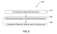
- FIG. 8is a flow chart of an exemplary embodiment of a method of making a powder as disclosed herein;
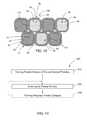
- FIG. 9is a schematic of illustration of an exemplary embodiment of adjacent first and second powder particles of a powder composite made using a powder mixture having single-layer coated powder particles;
- FIG. 10is a schematic illustration of an exemplary embodiment of a powder composite as disclosed herein formed from a first powder and a second powder and having a homogenous multi-modal distribution of particle sizes;
- FIG. 11is a schematic illustration of an exemplary embodiment of a powder composite as disclosed herein formed from a first powder and a second powder and having a non-homogeneous multi-modal distribution of particle sizes.
- FIG. 12is a schematic of illustration of another exemplary embodiment of adjacent first and second powder particles of a powder composite of made using a powder mixture having multilayer coated powder particles;
- FIG. 13is a schematic cross-sectional illustration of an exemplary embodiment of a precursor powder composite.
- FIG. 14is a flowchart of an exemplary method of making a powder composite as disclosed herein.
- Lightweight, high-strength metallic materialsare disclosed that may be used in a wide variety of applications and application environments, including use in various wellbore environments to make various selectably and controllably disposable or degradable lightweight, high-strength downhole tools or other downhole components, as well as many other applications for use in both durable and disposable or degradable articles.
- These lightweight, high-strength and selectably and controllably degradable materialsinclude fully-dense, sintered powder composites formed from coated powder materials that include various lightweight particle cores and core materials having various single layer and multilayer nanoscale coatings.
- These powder compositesare made from coated metallic powders that include various electrochemically-active (e.g., having relatively higher standard oxidation potentials) lightweight, high-strength particle cores and core materials, such as electrochemically active metals, that are dispersed within a cellular nanomatrix formed from the various nanoscale metallic coating layers of metallic coating materials, and are particularly useful in wellbore applications.
- These powder compositesalso include dispersed metallized carbon nanoparticles.
- the carbon nanoparticlesmay also be coated with various single layer and multilayer nanoscale coatings, which may include the same coatings that are used to coat the metal particle cores.
- the metallized carbon nanoparticlesact as strengthening agents within the microstructure of the powder composite.
- the coatings for the carbon nanoparticlesare also incorporated into the cellular nanomatrix.
- these powder compositesprovide a unique and advantageous combination of mechanical strength properties, such as compression and shear strength, low density and selectable and controllable corrosion properties, particularly rapid and controlled dissolution in various wellbore fluids.
- the particle core and coating layers of these powdersmay be selected to provide sintered powder composites suitable for use as high strength engineered materials having a compressive strength and shear strength comparable to various other engineered materials, including carbon, stainless and alloy steels, but which also have a low density comparable to various polymers, elastomers, low-density porous ceramics and composite materials.
- these powders and powder composite materialsmay be configured to provide a selectable and controllable degradation or disposal in response to a change in an environmental condition, such as a transition from a very low dissolution rate to a very rapid dissolution rate in response to a change in a property or condition of a wellbore proximate an article formed from the composite, including a property change in a wellbore fluid that is in contact with the powder composite.
- the selectable and controllable degradation or disposal characteristics describedalso allow the dimensional stability and strength of articles, such as wellbore tools or other components, made from these materials to be maintained until they are no longer needed, at which time a predetermined environmental condition, such as a wellbore condition, including wellbore fluid temperature, pressure or pH value, may be changed to promote their removal by rapid dissolution.
- a predetermined environmental conditionsuch as a wellbore condition, including wellbore fluid temperature, pressure or pH value
- a metallic powder that may be used to fashion precursor powder composite 100 ( FIG. 13 ) and powder composites 200 ( FIGS. 9-12 )comprises a first powder 10 that includes a plurality of metallic, coated first powder particles 12 and second powder 30 that includes a plurality of second powder particles 32 that comprise carbon nanoparticles.
- First powder particles 12 and second powder particles 32may be formed and intermixed to provide a powder mixture 5 ( FIG. 7 ), including free-flowing powder, that may be poured or otherwise disposed in all manner of forms or molds (not shown) having all manner of shapes and sizes and that may be used to fashion precursor powder composites 100 ( FIG. 13 ) and powder composites 200 ( FIGS. 9-12 ), as described herein, that may be used as, or for use in manufacturing, various articles of manufacture, including various wellbore tools and components.
- Each of the metallic, coated first powder particles 12 of first powder 10includes a first particle core 14 and a first metallic coating layer 16 disposed on the particle core 14 .
- the particle core 14includes a first core material 18 .
- the core material 18may include any suitable material for forming the particle core 14 that provides powder particle 12 that can be sintered to form a lightweight, high-strength powder composite 200 having selectable and controllable dissolution characteristics.
- Suitable core materialsinclude electrochemically active metals having a standard oxidation potential greater than or equal to that of Zn, including Mg, Al, Mn or Zn or a combination thereof.
- Electrochemically active metalsare very reactive with a number of common wellbore fluids, including any number of ionic fluids or highly polar fluids, such as those that contain various chlorides. Examples include fluids comprising potassium chloride (KCl), hydrochloric acid (HCl), calcium chloride (CaCl 2 ), calcium bromide (CaBr 2 ) or zinc bromide (ZnBr 2 ).
- Core material 18may also include other metals that are less electrochemically active than Zn or non-metallic materials, or a combination thereof. Suitable non-metallic materials include ceramics, composites, glasses or carbon, or a combination thereof.
- Core material 18may be selected to provide a high dissolution rate in a predetermined wellbore fluid, but may also be selected to provide a relatively low dissolution rate, including zero dissolution, where rapid dissolution of the nanomatrix material causes the particle core 14 to be rapidly undermined and liberated from the particle composite at the interface with the wellbore fluid, such that the effective rate of dissolution of particle composites made using particle cores 14 of these core materials 18 is high, even though core material 18 itself may have a low dissolution rate, including core materials that may be substantially insoluble in the wellbore fluid.
- these metalsmay be used as pure metals or in any combination with one another, including various alloy combinations of these materials, including binary, tertiary, or quaternary alloys of these materials. These combinations may also include composites of these materials. Further, in addition to combinations with one another, the Mg, Al, Mn or Zn core materials 18 may also include other constituents, including various alloying additions, to alter one or more properties of the particle cores 14 , such as by improving the strength, lowering the density or altering the dissolution characteristics of the core material 18 .
- Mgeither as a pure metal or an alloy or a composite material, is particularly useful, because of its low density and ability to form high-strength alloys, as well as its high degree of electrochemical activity, since it has a standard oxidation potential higher than Al, Mn or Zn.
- Mg alloysinclude all alloys that have Mg as an alloy constituent.
- Mg alloys that combine other electrochemically active metals, as described herein, as alloy constituentsare particularly useful, including binary Mg—Zn, Mg—Al and Mg—Mn alloys, as well as tertiary Mg—Zn—Y and Mg—Al—X alloys, where X includes Zn, Mn, Si, Ca or Y, or a combination thereof.
- Mg—Al—X alloysmay include, by weight, up to about 85% Mg, up to about 15% Al and up to about 5% X.
- Particle core 14 and core material 18 , and particularly electrochemically active metals including Mg, Al, Mn or Zn, or combinations thereof,may also include a rare earth element or combination of rare earth elements.
- rare earth elementsinclude Sc, Y, La, Ce, Pr, Nd or Er, or a combination of rare earth elements. Where present, a rare earth element or combinations of rare earth elements may be present, by weight, in any suitable amount, including in an amount of about 5% or less.
- T P1includes the lowest temperature at which incipient melting or liquation or other forms of partial melting occur within core material 18 , regardless of whether core material 18 comprises a pure metal, an alloy with multiple phases having different melting temperatures or a composite of materials having different melting temperatures.
- Particle cores 14may have any suitable particle size or range of particle sizes or distribution of particle sizes.
- the particle cores 14may be selected to provide an average particle size that is represented by a normal or Gaussian type unimodal distribution around an average or mean, as illustrated generally in FIG. 1 .
- particle cores 14may be selected or mixed to provide a multimodal distribution of particle sizes, including a plurality of average particle core sizes, such as, for example, a homogeneous bimodal distribution of average particle sizes, as illustrated generally and schematically in FIG. 6 .
- the selection of the distribution of particle core sizemay be used to determine, for example, the particle size and interparticle spacing 15 of the particles 12 of first powder 10 .
- the particle cores 14may have a unimodal distribution and an average particle diameter of about 5 ⁇ m to about 300 ⁇ m, more particularly about 80 ⁇ m to about 120 ⁇ m, and even more particularly about 100 ⁇ m.
- Particle cores 14may have any suitable particle shape, including any regular or irregular geometric shape, or combination thereof.
- particle cores 14are substantially spheroidal electrochemically active metal particles.
- particle cores 14may include substantially irregularly shaped ceramic particles.
- particle cores 14may include carbon nanotube, flat graphene or spherical nanodiamond structures, or hollow glass microspheres, or combinations thereof.
- Each of the metallic, coated powder particles 12 of first powder 10also includes a metallic coating layer 16 that is disposed on particle core 14 .
- Metallic coating layer 16includes a metallic coating material 20 .
- Metallic coating material 20gives the powder particles 12 and first powder 10 its metallic nature.
- Metallic coating layer 16is a nanoscale coating layer.
- metallic coating layer 16may have a thickness of about 25 nm to about 2500 nm. The thickness of metallic coating layer 16 may vary over the surface of particle core 14 , but will preferably have a substantially uniform thickness over the surface of particle core 14 .
- Metallic coating layer 16may include a single layer, as illustrated in FIG. 2 , or a plurality of layers as a multilayer coating structure, as illustrated in FIGS. 3-5 for up to four layers.
- the metallic coating layer 16may include a single constituent chemical element or compound, or may include a plurality of chemical elements or compounds. Where a layer includes a plurality of chemical constituents or compounds, they may have all manner of homogeneous or heterogeneous distributions, including a homogeneous or heterogeneous distribution of metallurgical phases. This may include a graded distribution where the relative amounts of the chemical constituents or compounds vary according to respective constituent profiles across the thickness of the layer. In both single layer and multilayer metallic coatings 16 , each of the respective layers, or combinations of them, may be used to provide a predetermined property to the powder particles 12 or a sintered powder composite formed therefrom.
- the predetermined propertymay include the bond strength of the metallurgical bond between the particle core 14 and the coating material 20 ; the interdiffusion characteristics between the particle core 14 and metallic coating layer 16 , including any interdiffusion between the layers of a multilayer coating layer 16 ; the interdiffusion characteristics between the various layers of a multilayer coating layer 16 ; the interdiffusion characteristics between the metallic coating layer 16 of one powder particle and that of an adjacent powder particle 12 ; the bond strength of the metallurgical bond between the metallic coating layers of adjacent sintered powder particles 12 , including the outermost layers of multilayer coating layers; and the electrochemical activity of the coating layer 16 .
- T C1includes the lowest temperature at which incipient melting or liquation or other forms of partial melting occur within coating material 20 , regardless of whether coating material 20 comprises a pure metal, an alloy with multiple phases each having different melting temperatures or a composite, including a composite comprising a plurality of coating material layers having different melting temperatures.
- Metallic coating material 20may include any suitable metallic coating material 20 that provides a sinterable outer surface 21 that is configured to be sintered to an adjacent powder particle 12 that also has a metallic coating layer 16 and sinterable outer surface 21 .
- the sinterable outer surface 21 of metallic coating layer 16is also configured to be sintered to a sinterable outer surface 21 of second particles 32 .
- the first powder particles 12 and second powder particles 32are sinterable at a predetermined sintering temperature (T S ) that is a function of the first and second core materials 18 , 38 and first and second coating materials 20 , 40 , such that sintering of powder composite 200 is accomplished entirely in the solid state and where T S is less than T P1 , T P2 , T C1 , and T C2 .
- T Spredetermined sintering temperature
- liquid phase sinteringwould provide for rapid interdiffusion of the particle core and metallic coating layer materials and make it difficult to limit the growth of and provide control over the resultant interface between them, and thus interfere with the formation of the desirable microstructure of particle composite 200 as described herein.
- core material 18will be selected to provide a core chemical composition and the coating material 20 will be selected to provide a coating chemical composition and these chemical compositions will also be selected to differ from one another.
- the core material 18will be selected to provide a core chemical composition and the coating material 20 will be selected to provide a coating chemical composition and these chemical compositions will also be selected to differ from one another at their interface.
- Differences in the chemical compositions of coating material 20 and core material 18may be selected to provide different dissolution rates and selectable and controllable dissolution of powder composites 200 that incorporate them making them selectably and controllably dissolvable. This includes dissolution rates that differ in response to a changed condition in the wellbore, including an indirect or direct change in a wellbore fluid.
- a powder composite 200 formed from first powder 10 having chemical compositions of core material 18 and coating material 20 that make composite 200is selectably dissolvable in a wellbore fluid in response to a changed wellbore condition that includes a change in temperature, change in pressure, change in flow rate, change in pH or change in chemical composition of the wellbore fluid, or a combination thereof.
- the selectable dissolution response to the changed conditionmay result from actual chemical reactions or processes that promote different rates of dissolution, but also encompass changes in the dissolution response that are associated with physical reactions or processes, such as changes in wellbore fluid pressure or flow rate.
- particle core 14includes Mg, Al, Mn or Zn, or a combination thereof, as core material 18 , and more particularly may include pure Mg and Mg alloys, and metallic coating layer 16 includes Al, Zn, Mn, Mg, Mo, W, Cu, Fe, Si, Ca, Co, Ta, Re, or Ni, or an oxide, nitride or a carbide thereof, or a combination of any of the aforementioned materials as coating material 20 .
- particle core 14includes Mg, Al, Mn or Zn, or a combination thereof, as core material 18 , and more particularly may include pure Mg and Mg alloys, and metallic coating layer 16 includes a single layer of Al or Ni, or a combination thereof, as coating material 20 , as illustrated in FIG. 2 .
- metallic coating layer 16includes a combination of two or more constituents, such as Al and Ni, the combination may include various graded or co-deposited structures of these materials where the amount of each constituent, and hence the composition of the layer, varies across the thickness of the layer, as also illustrated in FIG. 2 .
- particle core 14includes Mg, Al, Mn or Zn, or a combination thereof, as core material 18 , and more particularly may include pure Mg and Mg alloys
- coating layer 16includes two layers as core material 20 , as illustrated in FIG. 3 .
- the first layer 22is disposed on the surface of particle core 14 and includes Al or Ni, or a combination thereof, as described herein.
- the second layer 24is disposed on the surface of the first layer and includes Al, Zn, Mg, Mo, W, Cu, Fe, Si, Ca, Co, Ta, Re or Ni, or a combination thereof, and the first layer has a chemical composition that is different than the chemical composition of the second layer.
- first layer 22will be selected to provide a strong metallurgical bond to particle core 14 and to limit interdiffusion between the particle core 14 and coating layer 16 , particularly first layer 22 .
- Second layer 24may be selected to increase the strength of the metallic coating layer 16 , or to provide a strong metallurgical bond and promote sintering with the second layer 24 of adjacent powder particles 12 , or both.
- the respective layers of metallic coating layer 16may be selected to promote the selective and controllable dissolution of the coating layer 16 in response to a change in a property of the wellbore, including the wellbore fluid, as described herein.
- thisis only exemplary and it will be appreciated that other selection criteria for the various layers may also be employed.
- any of the respective layersmay be selected to promote the selective and controllable dissolution of the coating layer 16 in response to a change in a property of the wellbore, including the wellbore fluid, as described herein.
- Exemplary embodiments of a two-layer metallic coating layers 16 for use on particles cores 14 comprising Mginclude first/second layer combinations comprising Al/Ni and Al/W.
- particle core 14includes Mg, Al, Mn or Zn, or a combination thereof, as core material 18 , and more particularly may include pure Mg and Mg alloys
- coating layer 16includes three layers, as illustrated in FIG. 4 .
- the first layer 22is disposed on particle core 14 and may include Al or Ni, or a combination thereof.
- the second layer 24is disposed on first layer 22 and may include Al, Zn, Mg, Mo, W, Cu, Fe, Si, Ca, Co, Ta, Re or Ni, or an oxide, nitride or a carbide thereof, or a combination of any of the aforementioned second layer materials.
- the third layer 26is disposed on the second layer 24 and may include Al, Mn, Fe, Co, Ni or a combination thereof.
- first layer 22may be selected to provide a strong metallurgical bond to particle core 14 and to limit interdiffusion between the particle core 14 and coating layer 16 , particularly first layer 22 .
- Second layer 24may be selected to increase the strength of the metallic coating layer 16 , or to limit interdiffusion between particle core 14 or first layer 22 and outer or third layer 26 , or to promote adhesion and a strong metallurgical bond between third layer 26 and first layer 22 , or any combination of them.
- Third layer 26may be selected to provide a strong metallurgical bond and promote sintering with the third layer 26 of adjacent powder particles 12 .
- thisis only exemplary and it will be appreciated that other selection criteria for the various layers may also be employed.
- any of the respective layersmay be selected to promote the selective and controllable dissolution of the coating layer 16 in response to a change in a property of the wellbore, including the wellbore fluid, as described herein.
- An exemplary embodiment of a three-layer coating layer for use on particles cores comprising Mginclude first/second/third layer combinations comprising Al/Al 2 O 3 /Al.
- particle core 14includes Mg, Al, Mn or Zn, or a combination thereof, as core material 18 , and more particularly may include pure Mg and Mg alloys
- coating layer 16includes four layers, as illustrated in FIG. 5 .
- the first layer 22may include Al or Ni, or a combination thereof, as described herein.
- the second layer 24may include Al, Zn, Mg, Mo, W, Cu, Fe, Si, Ca, Co, Ta, Re or Ni or an oxide, nitride, carbide thereof, or a combination of the aforementioned second layer materials.
- the third layer 26may also include Al, Zn, Mg, Mo, W, Cu, Fe, Si, Ca, Co, Ta, Re or Ni, or an oxide, nitride or carbide thereof, or a combination of any of the aforementioned third layer materials.
- the fourth layer 28may include Al, Mn, Fe, Co, Ni or a combination thereof.
- the chemical composition of adjacent layersis different, such that the chemical composition of first layer 22 is different than the chemical composition of second layer 24 , the chemical composition is of second layer 24 different than the chemical composition of third layer 26 , and the chemical composition of third layer 26 is different than the chemical composition of fourth layer 28 .
- the selection of the various layerswill be similar to that described for the three-layer configuration above with regard to the inner (first) and outer (fourth) layers, with the second and third layers available for providing enhanced interlayer adhesion, strength of the overall metallic coating layer 16 , limited interlayer diffusion or selectable and controllable dissolution, or a combination thereof.
- thisis only exemplary and it will be appreciated that other selection criteria for the various layers may also be employed.
- any of the respective layersmay be selected to promote the selective and controllable dissolution of the coating layer 16 in response to a change in a property of the wellbore, including the wellbore fluid, as described herein.
- the thickness of the various layers in multi-layer configurationsmay be apportioned between the various layers in any manner so long as the sum of the layer thicknesses provide a nanoscale coating layer 16 , including layer thicknesses as described herein.
- the first layer 22 and outer layermay be thicker than other layers, where present, due to the desire to provide sufficient material to promote the desired bonding of first layer 22 with the particle core 14 , or the bonding of the outer layers of adjacent powder particles 12 , during sintering of powder composite 200 .
- First powder 10also includes an additional or second powder 30 interspersed in the plurality of first powder particles 12 , as illustrated in FIG. 7 .
- the second powder 30includes a plurality of second powder particles 32 .
- Second powder particles 32comprise second particle cores 34 that include second particle core material 38 .
- Second particle core material 38may include various carbon nanomaterials, including various carbon nanoparticles, and more particularly nanometer-scale particulate allotropes of carbon. This may include any suitable allotropic form of carbon, including any solid particulate allotrope, and particularly including any nanoparticles comprising graphene, fullerene or nanodiamond particle structures.
- Suitable fullerenesmay include buckeyballs, buckeyball clusters, buckeypapers or nanotubes, including single-wall nanotubes and multi-wall nanotubes. Fullerenes also include three-dimensional polymers of any of the above. Suitable fullerenes may also include metallofullerenes, or those which encompass various metals or metal ions. Buckeyballs may include any suitable ball size or diameter, including substantially spheroidal configurations having any number of carbon atoms, including C 60 , C 70 , C 76 , C 84 and the like. Both single-wall and multi-wall nanotubes are substantially cylindrical may have any predetermined tube length or tube diameter, or combination thereof. Multi-wall nanotubes may have any predetermined number of walls.
- Nanodiamondmay include any suitable spheroidal configuration having any predetermined spherical diameter, including a plurality of different predetermined diameters.
- Second particle core 34 and second core material 38have a melting temperature (T P2 ).
- T P2includes the lowest temperature at which incipient melting or liquation or other forms of partial melting occur within second core material 38 .
- Second particle cores 34may have any suitable particle size or range of particle sizes or distribution of particle sizes.
- the second particle cores 34may be selected to provide an average particle size that is represented by a normal or Gaussian type unimodal distribution around an average or mean, similar to that illustrated generally for the first particle cores 14 in FIG. 1 .
- second particle cores 34may be selected or mixed to provide a multimodal distribution of particle sizes, including a plurality of average particle core sizes, such as, for example, a homogeneous bimodal distribution of average particle sizes, similar to that illustrated generally and schematically for the first particle cores 14 in FIG. 6 .
- first and second powder particles 12 , 32may have unimodal or multimodal particle size distribution
- powder mixture 5may have a unimodal or multimodal distribution of particle sizes. Further, the mixture of first and second powder particles may be homogeneous or heterogeneous.
- These second powder particles 32may be selected to change a physical, chemical, mechanical or other property of a powder particle composite 200 formed from first powder 10 and second powder 30 , or a combination of such properties.
- the property changemay include an increase in the compressive strength of powder composite 200 formed from first powder 10 and second powder 30 .
- the second powder 30may be selected to promote the selective and controllable dissolution of in particle composite 200 formed from first powder 10 and second powder 30 in response to a change in a property of the wellbore, including the wellbore fluid, as described herein.
- Second powder particles 32include uncoated second particle cores 34 or may include second particle cores 34 that are coated with a metallic coating layer 36 .
- the coating layer 36 of second powder particles 32may comprise the same coating material 40 as coating material 20 of powder particles 12 , or the coating material 40 may be different.
- any of the exemplary single layer and multilayer metallic coating layer 16 combinations described hereinmay also be disposed on the second particle cores 34 as second metallic coating layers 36 .
- the second powder particles 32 (uncoated) or particle cores 34may include any suitable carbon nanoparticle to provide the desired benefit.
- suitable second powder particles 32 having second particle cores 34may include the exemplary carbon nanoparticles described herein.
- second powder particles 32will also be configured for solid state sintering to powder particles 12 at the predetermined sintering temperature (T S ), particle cores 34 will have a melting temperature T P2 and any coating layers 36 will have a second melting temperature T C2 , where T S is also less than T P2 and T C2 .
- second powder 30is not limited to one additional powder particle 32 type (i.e., a second powder particle), but may include a plurality of second powder particles 32 (i.e., second, third, fourth, etc. types of second powder particles 32 ) in any number.
- Uncoated second particles 32may also include functionalized carbon nanoparticles that do not include a metallic coating layer but are functionalized with any desired chemical functionality using any suitable chemical or physical bonding of the chemical functionality. Functionalized carbon nanoparticles may be used to assist the bonding of the carbon nanoparticles into the nanomatrix material 220 .
- Method 300includes forming 310 a plurality of first or second particle cores 14 , 34 , as described herein.
- Method 300also includes depositing 320 a first or second metallic coating layer 16 , 36 on each of the plurality of respective first or second particle cores 14 , 34 .
- Depositing 320is the process by which first or second coating layer 16 , 36 is disposed on each of respective first or second particle cores 14 , 34 as described herein.
- Forming 310 of first or second particle cores 14 , 34may be performed by any suitable method for forming a plurality of first or second particle cores 14 , 34 of the desired first or second core material 18 , 38 , which essentially comprise methods of forming a powder of first or second core material 18 , 38 .
- Suitable metal powder forming methods for first particle core 14may include mechanical methods; including machining, milling, impacting and other mechanical methods for forming the metal powder; chemical methods, including chemical decomposition, precipitation from a liquid or gas, solid-solid reactive synthesis, chemical vapor deposition and other chemical powder forming methods; atomization methods, including gas atomization, liquid and water atomization, centrifugal atomization, plasma atomization and other atomization methods for forming a powder; and various evaporation and condensation methods.
- first particle cores 14 comprising Mgmay be fabricated using an atomization method, such as vacuum spray forming or inert gas spray forming.
- second particle cores 34 comprising carbon nanotubesmay be formed using arc discharge, laser ablation, high pressure carbon monoxide or chemical vapor deposition.
- Depositing 320 of first or second metallic coating layers 16 , 36 on the plurality of respective first or second particle cores 14 , 34may be performed using any suitable deposition method, including various thin film deposition methods, such as, for example, chemical vapor deposition and physical vapor deposition methods.
- depositing 320 of first or second metallic coating layers 16 , 36may be performed using fluidized bed chemical vapor deposition (FBCVD).
- FBCVDfluidized bed chemical vapor deposition
- Depositing 320 of the first or second metallic coating layers 16 , 36 by FBCVDincludes flowing a reactive fluid as a coating medium that includes the desired first or second metallic coating material 20 , 40 through a bed of respective first or second particle cores 14 , 34 fluidized in a reactor vessel under suitable conditions, including temperature, pressure and flow rate conditions and the like, sufficient to induce a chemical reaction of the coating medium to produce the desired first or second metallic coating material 20 , 40 and induce its deposition upon the surface of first or second particle cores 14 , 34 to form first or second coated powder particles 12 , 32 .
- the reactive fluid selectedwill depend upon the metallic coating material 20 desired, and will typically comprise an organometallic compound that includes the metallic material to be deposited, such as nickel tetracarbonyl (Ni(CO) 4 ), tungsten hexafluoride (WF 6 ), and triethyl aluminum (C 6 H 15 Al), that is transported in a carrier fluid, such as helium or argon gas.
- an organometallic compoundthat includes the metallic material to be deposited, such as nickel tetracarbonyl (Ni(CO) 4 ), tungsten hexafluoride (WF 6 ), and triethyl aluminum (C 6 H 15 Al)
- a carrier fluidsuch as helium or argon gas.
- the reactive fluidcauses at least a portion of the plurality of first or second particle cores 14 , 34 to be suspended in the fluid, thereby enabling the entire surface of the respective first or second suspended particle cores 14 , 34 to be exposed to the reactive fluid, including, for example, a desired organometallic constituent, and enabling deposition of first or second metallic coating materials 20 , 40 and first or second coating layers 16 , 36 over the entire surfaces of first or second particle cores 14 , 34 such that they each become enclosed forming first or second coated particles 12 , 32 having first or second metallic coating layers 16 , 36 , as described herein.
- each first or second metallic coating layer 16 , 36may include a plurality of coating layers.
- First or second coating material 20 , 40may be deposited in multiple layers to form a multilayer first or second metallic coating layer 16 , 36 by repeating the step of depositing 320 described above and changing 330 the reactive fluid to provide the desired first or second metallic coating material 20 , 40 for each subsequent layer, where each subsequent layer is deposited on the outer surface of respective first or second particle cores 14 , 34 that already include any previously deposited coating layer or layers that make up first or second metallic coating layer 16 , 36 .
- the first or second metallic coating materials 20 , 40 of the respective layersmay be different from one another, and the differences may be provided by utilization of different reactive media that are configured to produce the desired first or second metallic coating layers 16 , 36 on the first or second particle cores 14 , 34 in the fluidize bed reactor.
- first and second particle cores 14 , 34 and first and second core materials 18 , 38 and first and second metallic coating layers 16 , 36 and first and second coating material 20 , 40may be selected to provide first and second powder particles 12 , 32 and a first and second powders 10 , 30 that may be combined into a mixture as described herein and configured for compaction and sintering to provide a powder composite 200 that is lightweight (i.e., having a relatively low density), high-strength and is selectably and controllably removable from a wellbore in response to a change in a wellbore property, including being selectably and controllably dissolvable in an appropriate wellbore fluid, including various wellbore fluids as disclosed herein.
- Powder composite 200includes a substantially-continuous, cellular nanomatrix 216 of a nanomatrix material 220 having a plurality of dispersed first particles 214 and dispersed second particles 234 dispersed throughout the cellular nanomatrix 216 .
- the substantially-continuous cellular nanomatrix 216 and nanomatrix material 220 formed of sintered first and second metallic coating layers 16 , 36is formed by the compaction and sintering of the plurality of first and second metallic coating layers 16 , 36 of the plurality of first and second powder particles 12 , 32 .
- the chemical composition of nanomatrix material 220may be different than that of first or second coating materials 20 , 40 due to diffusion effects associated with the sintering as described herein.
- Powder metal composite 200also includes a plurality of first and second dispersed particles 214 , 234 that comprise first and second particle core materials 218 , 238 .
- First and second dispersed particle cores 214 , 234 and first and second core materials 218 , 238correspond to and are formed from the plurality of first and second particle cores 14 , 34 and first and second core materials 18 , 38 of the plurality of first and second powder particles 12 , 32 as the first and second metallic coating layers 16 , 36 are sintered together to form nanomatrix 216 .
- the chemical composition of first and second core materials 218 , 238may be different than that of first and second core material 18 , 38 due to diffusion effects associated with sintering as described herein.
- substantially-continuous cellular nanomatrix 216does not connote the major constituent of the powder composite, but rather refers to the minority constituent or constituents, whether by weight or by volume. This is distinguished from most matrix composite materials where the matrix comprises the majority constituent by weight or volume.
- substantially-continuous, cellular nanomatrixis intended to describe the extensive, regular, continuous and interconnected nature of the distribution of nanomatrix material 220 within powder composite 200 .
- substantially-continuousdescribes the extension of the nanomatrix material throughout powder composite 200 such that it extends between and envelopes substantially all of the first and second dispersed particles 214 , 234 .
- Substantially-continuousis used to indicate that complete continuity and regular order of the nanomatrix around each of first and second dispersed particle 214 , 234 is not required.
- defects in the first or second coating layers 16 , 36 over first or second particle cores 14 , 34 on some of first or second powder particles 12 , 32may cause some bridging of the first or second particle cores 14 , 34 during sintering of the powder composite 200 , thereby causing localized discontinuities to result within the cellular nanomatrix 216 , even though in the other portions of the powder composite the nanomatrix is substantially continuous and exhibits the structure described herein.
- nanomatrixdefines a network of generally repeating, interconnected, compartments or cells of nanomatrix material 220 that encompass and also interconnect the first and second dispersed particles 214 , 234 .
- nanomatrixis used to describe the size or scale of the matrix, particularly the thickness of the matrix between adjacent first or second dispersed particles 214 , 234 .
- the metallic coating layers that are sintered together to form the nanomatrixare themselves nanoscale thickness coating layers.
- first or second dispersed particles 214 , 234Since the nanomatrix at most locations, other than the intersection of more than two first or second dispersed particles 214 , 234 , generally comprises the interdiffusion and bonding of two first or second coating layers 16 , 36 from adjacent first or second powder particles 12 , 32 having nanoscale thicknesses, the matrix formed also has a nanoscale thickness (e.g., approximately two times the coating layer thickness as described herein) and is thus described as a nanomatrix.
- first or second dispersed particles 214 , 234does not connote the minor constituent of powder composite 200 , but rather refers to the majority constituent or constituents, whether by weight or by volume.
- the use of the term dispersed particleis intended to convey the discontinuous and discrete distribution of first or second particle core materials 218 , 238 within powder composite 200 .
- Powder composite 200may have any desired shape or size, including that of a cylindrical billet or bar that may be machined or otherwise used to form useful articles of manufacture, including various wellbore tools and components.
- the microstructure of powder composite 200includes an equiaxed configuration of first and second dispersed particles 214 , 234 that are dispersed throughout and embedded within the substantially-continuous, cellular nanomatrix 216 of sintered coating layers.
- This microstructureis somewhat analogous to an equiaxed grain microstructure with a continuous grain boundary phase, except that it does not require the use of alloy constituents having thermodynamic phase equilibria properties that are capable of producing such a structure. Rather, this equiaxed dispersed particle structure and cellular nanomatrix 216 of sintered first or second metallic coating layers 16 , 36 may be produced using constituents where thermodynamic phase equilibrium conditions would not produce an equiaxed structure.
- the equiaxed morphology of the first and second dispersed particles 214 , 234 and cellular nanomatrix 216 of particle layersresults from sintering and deformation of the first and second powder particles 12 , 32 as they are compacted and interdiffuse and deform to fill the interparticle spaces 15 ( FIG. 1 ).
- the sintering temperatures and pressuresmay be selected to ensure that the density of powder composite 200 achieves substantially full theoretical density.
- dispersed first and second particles 214 , 234are formed from first and second particle cores 14 , 34 dispersed in the cellular nanomatrix 216 of sintered first and second metallic coating layers 16 , 36 , and the nanomatrix 216 includes a solid-state metallurgical bond 217 or bond layer 219 , as illustrated schematically in FIG. 9 , extending between the first or second dispersed particles 214 , 234 throughout the cellular nanomatrix 216 that is formed at a sintering temperature (T S ), where T S is less than T C1 , T C2 and T P2 .
- T Ssintering temperature
- solid-state metallurgical bond 217is formed in the solid state by solid-state interdiffusion between the first or second coating layers 16 , 36 of adjacent first or second powder particles 12 , 32 that are compressed into touching contact during the compaction and sintering processes used to form powder composite 200 , as described herein.
- sintered coating layers 16 of cellular nanomatrix 216include a solid-state bond layer 219 that has a thickness (t) defined by the extent of the interdiffusion of the first or second coating materials 20 , 40 of the first or second coating layers 16 , 36 , which will in turn be defined by the nature of the coating layers 16 , including whether they are single or multilayer coating layers, whether they have been selected to promote or limit such interdiffusion, and other factors, as described herein, as well as the sintering and compaction conditions, including the sintering time, temperature and pressure used to form powder composite 200 .
- Nanomatrix 216As nanomatrix 216 is formed, including bond 217 and bond layer 219 , the chemical composition or phase distribution, or both, of first or second metallic coating layers 16 , 36 may change. Nanomatrix 216 also has a melting temperature (T M ). As used herein, T M includes the lowest temperature at which incipient melting or liquation or other forms of partial melting will occur within nanomatrix 216 , regardless of whether nanomatrix material 220 comprises a pure metal, an alloy with multiple phases each having different melting temperatures or a composite, including a composite comprising a plurality of layers of various coating materials having different melting temperatures, or a combination thereof, or otherwise.
- T Mincludes the lowest temperature at which incipient melting or liquation or other forms of partial melting will occur within nanomatrix 216 , regardless of whether nanomatrix material 220 comprises a pure metal, an alloy with multiple phases each having different melting temperatures or a composite, including a composite comprising a plurality of layers of various coating materials having
- dispersed first and second particles 214 , 234 and first and second particle core materials 218 , 238are formed in conjunction with nanomatrix 216 , diffusion of constituents of metallic coating layers 16 into the particle cores 14 is also possible, which may result in changes in the chemical composition or phase distribution, or both, of first or second particle cores 14 , 34 .
- dispersed first and second particles 214 , 234 and first and second particle core materials 218 , 238may have respective melting temperatures (T DP1 , T DP2 ) that are different than T P1 , T P2 .
- T DP1 , T DP2includes the lowest temperature at which incipient melting or liquation or other forms of partial melting will occur within dispersed first and second particles 214 , 234 , regardless of whether first or second particle core material 218 , 238 comprise a pure metal, an alloy with multiple phases each having different melting temperatures or a composite, or otherwise.
- Powder composite 200is formed at a sintering temperature (T S ), where T S is less than T C1 , T C1 , T P1 , T P2 , T M , T DP1 and T DP2 .
- Dispersed first and second particles 214 , 234may comprise any of the materials described herein for first and second particle cores 14 , 34 , even though the chemical composition of dispersed first and second particles 214 , 234 may be different due to diffusion effects as described herein.
- first dispersed particles 214are formed from first particle cores 14 comprising materials having a standard oxidation potential greater than or equal to Zn, including Mg, Al, Zn or Mn, or a combination thereof, may include various binary, tertiary and quaternary alloys or other combinations of these constituents as disclosed herein in conjunction with first particle cores 14 .
- first dispersed particles 214comprising Mg and the nanomatrix 216 formed from the metallic coating layers 16 described herein are particularly useful.
- Dispersed first particles 214 and first particle core material 218 of Mg, Al, Zn or Mn, or a combination thereof,may also include a rare earth element, or a combination of rare earth elements as disclosed herein in conjunction with particle cores 14 .
- dispersed second particles 234are formed from second particle core 34 comprising carbon nanoparticles, including buckeyballs, buckeyball clusters, buckeypaper, single-wall nanotubes and multi-wall nanotubes.
- dispersed particles 214are formed from particle cores 14 comprising metals that are less electrochemically active than Zn or non-metallic materials. Suitable non-metallic materials include ceramics, glasses (e.g., hollow glass microspheres) or carbon, or a combination thereof, as described herein.
- dispersed second particles 234are formed from second particle core 34 comprising carbon nanoparticles, including buckeyballs, buckeyball clusters, buckeypaper, single-wall nanotubes and multi-wall nanotubes.
- First and second dispersed particles 214 , 234 of powder composite 200may have any suitable particle size, including the average particle sizes described herein for first and second particle cores 14 , 34 .
- first and second dispersed particles 214 , 234may be affected by the selection of the first and second powder 10 , 30 or powders 10 , used to make particle composite 200 .
- First and second dispersed particles 214 , 234may have any suitable shape depending on the shape selected for first and second particle cores 14 , 34 and first and second powder particles 12 , 32 , as well as the method used to sinter and composite first powder 10 .
- first and second powder particles 12 , 32may be spheroidal or substantially spheroidal and first and second dispersed particles 214 , 234 may include an equiaxed particle configuration as described herein.
- first powder particles 12may be spheroidal or substantially spheroidal and second powder particles 32 may be planar, as in the case where they comprise graphene, or tubular, as in the case where they comprise nanotubes, or spheroidal, as in the case where they comprise buckeyballs, buckeyball clusters or nanodiamonds or other non-spherical forms.
- a non-equiaxed particle structure, or microstructuremay result where the second dispersed particles 234 extend between adjacent first particles 214 , or enfold or otherwise wrap around first particles 214 .
- Many non-equiaxed microstructuresmay be produced using a combination of substantially spherical first powder particles 12 and non-spherical powder particles 234 .
- the second powder particles 232may be uncoated such that dispersed second particles 234 are embedded within nanomatrix 216 .
- first powder 10 and second powder 30may be mixed to form a homogeneous dispersion of dispersed first particles 214 and dispersed second particles 234 , as illustrated in FIG. 10 , or to form a non-homogeneous dispersion of these particles, as illustrated in FIG. 11 .
- Nanomatrix 216is a substantially-continuous, cellular network of first and second metallic coating layers 16 , 36 that are sintered to one another.
- the thickness of nanomatrix 216will depend on the nature of the first powder 10 and second powder 30 , particularly the thicknesses of the coating layers associated with these powder particles.
- the thickness of nanomatrix 216is substantially uniform throughout the microstructure of powder composite 200 and comprises about two times the thickness of the first and second coating layers 16 , 36 of first and second powder particles 12 , 32 .
- the cellular nanomatrix 216has a substantially uniform average thickness between dispersed particles 214 of about 50 nm to about 5000 nm.
- Nanomatrix 216is formed by sintering metallic coating layers 16 of adjacent particles to one another by interdiffusion and creation of bond layer 219 as described herein.
- Metallic coating layers 16may be single layer or multilayer structures, and they may be selected to promote or inhibit diffusion, or both, within the layer or between the layers of metallic coating layer 16 , or between the metallic coating layer 16 and particle core 14 , or between the metallic coating layer 16 and the metallic coating layer 16 of an adjacent powder particle, the extent of interdiffusion of metallic coating layers 16 during sintering may be limited or extensive depending on the coating thicknesses, coating material or materials selected, the sintering conditions and other factors.
- nanomatrix 216 and nanomatrix material 220may be simply understood to be a combination of the constituents of first or second coating layers 16 , 36 that may also include one or more constituents of first or second dispersed particles 214 , 234 , depending on the extent of interdiffusion, if any, that occurs between the dispersed particles 214 and the nanomatrix 216 .
- first and second dispersed particles 214 , 234 and first and second particle core materials 218 , 238may be simply understood to be a combination of the constituents of respective first and second particle cores 14 , 34 that may also include one or more constituents of nanomatrix 216 and nanomatrix material 220 , depending on the extent of interdiffusion, if any, that occurs between the first and second dispersed particles 214 , 234 and the nanomatrix 216 .
- the nanomatrix material 220has a chemical composition and the first and second particle core materials 218 , 238 have a chemical composition that is different from that of nanomatrix material 220 , and the differences in the chemical compositions and the relative amounts, sizes, shapes and distributions of the first and second particles 12 , 32 may be configured to provide a selectable and controllable dissolution rate, including a selectable transition from a very low dissolution rate to a very rapid dissolution rate, in response to a controlled change in a property or condition of the wellbore proximate the composite 200 , including a property change in a wellbore fluid that is in contact with the powder composite 200 , as described herein.
- Nanomatrix 216may be formed from first and second powder particles 12 , 32 having single layer and multilayer first and second coating layers 16 , 36 . This design flexibility provides a large number of material combinations, particularly in the case of multilayer first and second coating layers 16 , 36 that can be utilized to tailor the cellular nanomatrix 216 and composition of nanomatrix material 220 by controlling the interaction of the coating layer constituents, both within a given layer, as well as between first or second coating layers 16 , 36 and the first or second particle cores 14 , 34 with which they are associated or a coating layer of an adjacent powder particle.
- Several exemplary embodiments that demonstrate this flexibilityare provided below.
- powder composite 200is formed from first and second powder particles 12 , 32 where the coating layer 16 comprises a single layer, and the resulting nanomatrix 216 between adjacent ones of the plurality of dispersed particles 214 comprises the single metallic first or second coating layer 16 , 36 of one of first or second powder particles 12 , 32 , a bond layer 219 and the single first or second coating layer 16 , 36 of another one of the adjacent first or second powder particles 12 , 32 .
- the thickness (t) of bond layer 219is determined by the extent of the interdiffusion between the single metallic first or second coating layers 16 , 36 and may encompass the entire thickness of nanomatrix 216 or only a portion thereof.
- powder composite 200may include dispersed first particles 214 comprising Mg, Al, Zn or Mn, or a combination thereof, second particles 234 may include carbon nanoparticles and nanomatrix 216 may include Al, Zn, Mn, Mg, Mo, W, Cu, Fe, Si, Ca, Co, Ta, Re or Ni, or an oxide, carbide or nitride thereof, or a combination of any of the aforementioned materials, including combinations where the nanomatrix material 220 of cellular nanomatrix 216 , including bond layer 219 , has a chemical composition and the first and second core materials 218 , 238 of dispersed first and second particles 214 , 234 have a chemical composition that are different than the chemical composition of nanomatrix material 216 .
- the difference in the chemical composition of the nanomatrix material 220 and the first and second core materials 218 , 238may be used to provide selectable and controllable dissolution in response to a change in a property of a wellbore, including a wellbore fluid, as described herein. They may also be selected to provide a selectable density or mechanical property, such as tensile strength, of powder composite 200 .
- dispersed first particles 214include Mg, Al, Zn or Mn, or a combination thereof
- dispersed second particles 234include carbon nanoparticles and the cellular nanomatrix 216 includes Al or Ni, or a combination thereof.
- powder composite 200is formed from first and second powder particles 12 , 32 where the first and second coating layers 16 , 36 comprise a multilayer coating having a plurality of coating layers, and the resulting nanomatrix 216 between adjacent ones of the plurality of first and second dispersed particles 214 , 234 comprise the plurality of layers (t) comprising the first or second coating layers 16 , 36 of one of first or second particles 12 , 32 , a bond layer 219 , and the plurality of layers comprising the first or second coating layers 16 , 36 of another one of first or second powder particles 12 , 32 .
- the thickness (t) of the bond layer 219is again determined by the extent of the interdiffusion between the plurality of layers of the respective first and second coating layers 16 , 36 , and may encompass the entire thickness of nanomatrix 216 or only a portion thereof.
- the plurality of layers comprising each of first and second coating layers 16 , 36may be used to control interdiffusion and formation of bond layer 219 and thickness (t).
- the compositeincludes dispersed first particles 214 comprising Mg, Al, Zn or Mn, or a combination thereof, as described herein, dispersed second particles 234 comprising carbon nanoparticles and nanomatrix 216 comprises a cellular network of sintered two-layer first and second coating layers 16 , 36 , as shown in FIG. 3 , comprising first layers 22 that are disposed on the dispersed first and second particles 214 , 234 and second layers 24 that are disposed on the first layers 22 .
- First layers 22include Al or Ni, or a combination thereof
- second layers 24include Al, Zn, Mn, Mg, Mo, W, Cu, Fe, Si, Ca, Co, Ta, Re or Ni, or a combination thereof.
- materials of dispersed particles 214 and multilayer first and second coating layers 16 , 36 used to form nanomatrix 216are selected so that the chemical compositions of adjacent materials are different (e.g. dispersed particle/first layer and first layer/second layer).
- the compositeincludes dispersed first particles 214 comprising Mg, Al, Zn or Mn, or a combination thereof, as described herein, dispersed second particles 234 comprising carbon nanoparticles and nanomatrix 216 comprises a cellular network of sintered three-layer metallic first and second coating layers 16 , 36 as shown in FIG. 4 , comprising first layers 22 that are disposed on the dispersed first and second particles 214 , 234 , second layers 24 that are disposed on the first layers 22 and third layers 26 that are disposed on the second layers 24 .
- First layers 22include Al or Ni, or a combination thereof; second layers 24 include Al, Zn, Mn, Mg, Mo, W, Cu, Fe, Si, Ca, Co, Ta, Re or Ni, or an oxide, nitride or carbide thereof, or a combination of any of the aforementioned second layer materials; and the third layers include Al, Zn, Mn, Mg, Mo, W, Cu, Fe, Si, Ca, Co, Ta, Re or Ni, or a combination thereof.
- the selection of materialsis analogous to the selection considerations described herein for powder composite 200 made using two-layer coating layer powders, but must also be extended to include the material used for the third coating layer.
- the compositeincludes dispersed first particles 214 comprising Mg, Al, Zn or Mn, or a combination thereof, as described herein, dispersed second particles 234 comprising carbon nanoparticles and nanomatrix 216 comprise a cellular network of sintered four-layer first and second coating layers 16 , 36 comprising first layers 22 that are disposed on the dispersed first and second particles 214 ; 234 second layers 24 that are disposed on the first layers 22 ; third layers 26 that are disposed on the second layers 24 and fourth layers 28 that are disposed on the third layers 26 .
- First layers 22include Al or Ni, or a combination thereof
- second layers 24include Al, Zn, Mn, Mg, Mo, W, Cu, Fe, Si, Ca, Co, Ta, Re or Ni, or an oxide, nitride or carbide thereof, or a combination of any of the aforementioned second layer materials
- third layersinclude Al, Zn, Mn, Mg, Mo, W, Cu, Fe, Si, Ca, Co, Ta, Re or Ni, or an oxide, nitride or carbide thereof, or a combination of any of the aforementioned third layer materials
- fourth layersinclude Al, Mn, Fe, Co or Ni, or a combination thereof.
- the selection of materialsis analogous to the selection considerations described herein for powder composites 200 made using two-layer coating layer powders, but must also be extended to include the material used for the third and fourth coating layers.
- dispersed first particles 214comprise a metal having a standard oxidation potential less than Zn or a non-metallic material, or a combination thereof, as described herein
- dispersed second particles 234comprising carbon nanoparticles and nanomatrix 216 comprises a cellular network of sintered metallic coating layers 16 .
- Suitable non-metallic materialsinclude various ceramics, glasses or forms of carbon, or a combination thereof.
- nanomatrix 216may include Al, Zn, Mn, Mg, Mo, W, Cu, Fe, Si, Ca, Co, Ta, Re or Ni, or an oxide, carbide or nitride thereof, or a combination of any of the aforementioned materials as nanomatrix material 220 .
- sintered powder composite 200may comprise a sintered precursor powder composite 100 that includes a plurality of deformed, mechanically bonded first and second powder particles 12 , 32 as described herein.
- Precursor powder composite 100may be formed by composition of first and second powders 10 , 30 to the point that first and second powder particles 12 , 32 are pressed into one another, thereby deforming them and forming interparticle mechanical or other bonds 110 associated with this deformation sufficient to cause the deformed powder particles 12 to adhere to one another and form a green-state powder composite having a green density that is less than the theoretical density of a fully-dense composite of first powder 10 , due in part to interparticle spaces 15 .
- Compactionmay be performed, for example, by isostatically pressing first and second powders 10 , 30 at room temperature to provide the deformation and interparticle bonding of first and second powder particles 12 , 32 necessary to form precursor powder composite 100 .
- Method 400includes forming 410 a powder mixture 5 comprising first and second coated metallic powders 10 , 30 comprising first and second powder particles 12 , 32 as described herein.
- Method 400also includes forming 420 a powder composite 200 by applying a predetermined temperature and a predetermined pressure to the coated first and second powder particles 12 , 32 sufficient to sinter them by solid-phase sintering of the first and second coating layers 16 , 36 to form a substantially-continuous, cellular nanomatrix 216 of a nanomatrix material 220 and a plurality of dispersed first and second particles 214 , 234 dispersed within nanomatrix 216 as described herein.
- the sinteringcomprises sintering of the first coating layers only.
- Forming 410 of the powder mixture 5may be performed by any suitable method.
- forming 410includes applying the metallic first and second coating layers 16 , 36 as described herein, to the first and second particle cores 14 , 34 as described herein, using fluidized bed chemical vapor deposition (FBCVD) as described herein.
- Applying the metallic coating layersmay include applying single-layer metallic coating layers or multilayer metallic coating layers as described herein. Applying the metallic coating layers may also include controlling the thickness of the individual layers as they are being applied, as well as controlling the overall thickness of metallic coating layers.
- Particle coresmay be formed as described herein.
- Forming 420 of the powder composite 200may include any suitable method of forming a fully-dense composite of powder mixture 5 .
- forming 420includes dynamic forging of a green-density precursor powder composite 100 to apply a predetermined temperature and a predetermined pressure sufficient to sinter and deform the powder particles and form a fully-dense nanomatrix 216 and dispersed first and second particles 214 , 234 as described herein.
- Dynamic forgingas used herein means dynamic application of a load at temperature and for a time sufficient to promote sintering of the metallic coating layers of adjacent first and second powder particles 12 , 32 and may preferably include application of a dynamic forging load at a predetermined loading rate for a time and at a temperature sufficient to form a sintered and fully-dense powder composite 200 .
- dynamic forgingmay include: 1) heating a precursor or green-state powder composite 100 to a predetermined solid phase sintering temperature, such as, for example, a temperature sufficient to promote interdiffusion between metallic coating layers of adjacent first and second powder particles 12 , 32 ; 2) holding the precursor powder composite 100 at the sintering temperature for a predetermined hold time, such as, for example, a time sufficient to ensure substantial uniformity of the sintering temperature throughout the precursor composite 100 ; 3) forging the precursor powder composite 100 to full density, such as, for example, by applying a predetermined forging pressure according to a predetermined pressure schedule or ramp rate sufficient to rapidly achieve full density while holding the composite at the predetermined sintering temperature; and 4) cooling the powder composite 200 to room temperature.
- a predetermined solid phase sintering temperaturesuch as, for example, a temperature sufficient to promote interdiffusion between metallic coating layers of adjacent first and second powder particles 12 , 32 .
- a predetermined hold timesuch as, for example, a time sufficient to ensure substantial uniform
- the predetermined pressure and predetermined temperature applied during forming 420will include a sintering temperature, T S , and forging pressure, P F , as described herein that will ensure solid-state sintering and deformation of the powder particles 12 to form fully-dense powder composite 200 , including solid-state bond 217 and bond layer 219 .
- the steps of heating to and holding the precursor powder composite 100 at the predetermined sintering temperature for the predetermined timemay include any suitable combination of temperature and time, and will depend, for example, on the powder 10 selected, including the materials used for first and second particle cores 14 , 34 and first and second metallic coating layers 16 , 36 the size of the precursor powder composite 100 , the heating method used and other factors that influence the time needed to achieve the desired temperature and temperature uniformity within precursor powder composite 100 .
- the predetermined pressuremay include any suitable pressure and pressure application schedule or pressure ramp rate sufficient to achieve a fully-dense powder composite 200 , and will depend, for example, on the material properties of the first and second powder particles 12 , 32 selected, including temperature dependent stress/strain characteristics (e.g., stress/strain rate characteristics), interdiffusion and metallurgical thermodynamic and phase equilibria characteristics, dislocation dynamics and other material properties.
- temperature dependent stress/strain characteristicse.g., stress/strain rate characteristics
- interdiffusion and metallurgical thermodynamic and phase equilibria characteristicse.g., dislocation dynamics and other material properties.
- the maximum forging pressure of dynamic forging and the forging schedulei.e., the pressure ramp rates that correspond to strain rates employed
- the pressure ramp ratesthat correspond to strain rates employed
- the maximum forging pressure and forging ramp rate(i.e., strain rate) is the pressure just below the composite cracking pressure, i.e., where dynamic recovery processes are unable to relieve strain energy in the composite microstructure without the formation of a crack in the composite.
- strain rateis the pressure just below the composite cracking pressure, i.e., where dynamic recovery processes are unable to relieve strain energy in the composite microstructure without the formation of a crack in the composite.
- relatively higher forging pressures and ramp ratesmay be used. If relatively higher toughness of the powder composite is needed, relatively lower forging pressures and ramp rates may be used.
- predetermined hold timesof about 1 to about 5 hours may be used.
- the predetermined sintering temperature, T Swill preferably be selected as described herein to avoid melting of either first or second particle cores 14 , 34 or first or second metallic coating layers 16 , 36 as they are transformed during method 400 to provide dispersed first and second particles 214 , 234 and nanomatrix 216 .
- dynamic forgingmay include application of a forging pressure, such as by dynamic pressing to a maximum of about 80 ksi at a pressure ramp rate of about 0.5 to about 2 ksi/second.
- first particle cores 14include Mg and metallic coating layer 16 includes various single and multilayer coating layers as described herein, such as various single and multilayer coatings comprising Al
- the dynamic forgingmay be performed by sintering at a temperature, T S , of about 450° C. to about 470° C. for up to about 1 hour without the application of a forging pressure, followed by dynamic forging by application of isostatic pressures at ramp rates between about 0.5 to about 2 ksi/second to a maximum pressure, P s , of about 30 ksi to about 60 ksi, which may result in forging cycles of 15 seconds to about 120 seconds.
- the short duration of the forging cycleis a significant advantage as it limits interdiffusion, including interdiffusion within first and coating layers 16 , 36 , interdiffusion between adjacent metallic first and second coating layers 16 , 36 and interdiffusion between first and second coating layers 16 , 36 and respective first and second particle cores 14 , 34 to that needed to form metallurgical bond 217 and bond layer 219 , while also maintaining the desired microstructure, such as equiaxed dispersed first and second particle 214 , 234 shapes, with the integrity of cellular nanomatrix 216 strengthening phase.
- the duration of the dynamic forging cycleis much shorter than the forming cycles and sintering times required for conventional powder composite forming processes, such as hot isostatic pressing (HIP), pressure assisted sintering or diffusion sintering.
- HIPhot isostatic pressing
- Method 400may also optionally include forming 430 a precursor powder composite by compaction the plurality of first and second powder particles 12 , 32 sufficiently to deform the particles and form interparticle bonds to one another and form the precursor powder composite 100 prior to forming 420 the powder composite.
- Compaction 430may include pressing, such as isostatic pressing, of the plurality of powder particles 12 at room temperature to form precursor powder composite 100 .
- powder 10may include first particle cores 14 comprising Mg and forming 430 the precursor powder composite may be performed at room temperature at an isostatic pressure of about 10 ksi to about 60 ksi.
Landscapes
- Chemical & Material Sciences (AREA)
- Engineering & Computer Science (AREA)
- Materials Engineering (AREA)
- Mechanical Engineering (AREA)
- Metallurgy (AREA)
- Organic Chemistry (AREA)
- Inorganic Chemistry (AREA)
- Nanotechnology (AREA)
- Powder Metallurgy (AREA)
- Manufacture Of Alloys Or Alloy Compounds (AREA)
- Catalysts (AREA)
Abstract
Description
Claims (27)
Priority Applications (12)
| Application Number | Priority Date | Filing Date | Title |
|---|---|---|---|
| US12/847,594US8425651B2 (en) | 2010-07-30 | 2010-07-30 | Nanomatrix metal composite |
| GB1300395.9AGB2494365B (en) | 2010-07-30 | 2011-07-06 | Nanomatrix metal composite |
| AU2011283147AAU2011283147B2 (en) | 2010-07-30 | 2011-07-06 | Nanomatrix metal composite |
| PCT/US2011/043036WO2012015567A2 (en) | 2010-07-30 | 2011-07-06 | Nanomatrix metal composite |
| MYPI2013700165AMY163335A (en) | 2010-07-30 | 2011-07-06 | Nanomatrix metal composite |
| CN201180037374.5ACN103038005B (en) | 2010-07-30 | 2011-07-06 | Nanomatrix metal composite |
| NO20130051ANO346997B1 (en) | 2010-07-30 | 2011-07-06 | Nanomatrix metal composite material |
| CA2806714ACA2806714C (en) | 2010-07-30 | 2011-07-06 | Nanomatrix metal composite |
| BR112013002323-6ABR112013002323B1 (en) | 2010-07-30 | 2011-07-06 | METAL POWDER COMPOSITE |
| US13/194,361US9243475B2 (en) | 2009-12-08 | 2011-07-29 | Extruded powder metal compact |
| US13/194,374US9227243B2 (en) | 2009-12-08 | 2011-07-29 | Method of making a powder metal compact |
| DK201300060ADK178325B1 (en) | 2010-07-30 | 2013-01-30 | Nanomatrix metal composite |
Applications Claiming Priority (1)
| Application Number | Priority Date | Filing Date | Title |
|---|---|---|---|
| US12/847,594US8425651B2 (en) | 2010-07-30 | 2010-07-30 | Nanomatrix metal composite |
Publications (2)
| Publication Number | Publication Date |
|---|---|
| US20120024109A1 US20120024109A1 (en) | 2012-02-02 |
| US8425651B2true US8425651B2 (en) | 2013-04-23 |
Family
ID=45525379
Family Applications (1)
| Application Number | Title | Priority Date | Filing Date |
|---|---|---|---|
| US12/847,594Expired - Fee RelatedUS8425651B2 (en) | 2009-12-08 | 2010-07-30 | Nanomatrix metal composite |
Country Status (10)
| Country | Link |
|---|---|
| US (1) | US8425651B2 (en) |
| CN (1) | CN103038005B (en) |
| AU (1) | AU2011283147B2 (en) |
| BR (1) | BR112013002323B1 (en) |
| CA (1) | CA2806714C (en) |
| DK (1) | DK178325B1 (en) |
| GB (1) | GB2494365B (en) |
| MY (1) | MY163335A (en) |
| NO (1) | NO346997B1 (en) |
| WO (1) | WO2012015567A2 (en) |
Cited By (62)
| Publication number | Priority date | Publication date | Assignee | Title |
|---|---|---|---|---|
| US20110132143A1 (en)* | 2002-12-08 | 2011-06-09 | Zhiyue Xu | Nanomatrix powder metal compact |
| US20130000903A1 (en)* | 2011-06-30 | 2013-01-03 | James Crews | Reconfigurable cement composition, articles made therefrom and method of use |
| US20130047785A1 (en)* | 2011-08-30 | 2013-02-28 | Zhiyue Xu | Magnesium alloy powder metal compact |
| US20130047784A1 (en)* | 2011-08-30 | 2013-02-28 | Zhiyue Xu | Aluminum alloy powder metal compact |
| WO2015050678A1 (en)* | 2013-10-01 | 2015-04-09 | Baker Hughes Incorporated | Downhole flow inhibition tool and method of unplugging a seat |
| US20150101823A1 (en)* | 2013-10-15 | 2015-04-16 | Baker Hughes Incorporated | Seat apparatus and method |
| US9022107B2 (en) | 2009-12-08 | 2015-05-05 | Baker Hughes Incorporated | Dissolvable tool |
| US9033055B2 (en) | 2011-08-17 | 2015-05-19 | Baker Hughes Incorporated | Selectively degradable passage restriction and method |
| US9057242B2 (en) | 2011-08-05 | 2015-06-16 | Baker Hughes Incorporated | Method of controlling corrosion rate in downhole article, and downhole article having controlled corrosion rate |
| US9068428B2 (en) | 2012-02-13 | 2015-06-30 | Baker Hughes Incorporated | Selectively corrodible downhole article and method of use |
| US9079246B2 (en) | 2009-12-08 | 2015-07-14 | Baker Hughes Incorporated | Method of making a nanomatrix powder metal compact |
| US9080098B2 (en) | 2011-04-28 | 2015-07-14 | Baker Hughes Incorporated | Functionally gradient composite article |
| US9090955B2 (en) | 2010-10-27 | 2015-07-28 | Baker Hughes Incorporated | Nanomatrix powder metal composite |
| US9109429B2 (en) | 2002-12-08 | 2015-08-18 | Baker Hughes Incorporated | Engineered powder compact composite material |
| US9127515B2 (en) | 2010-10-27 | 2015-09-08 | Baker Hughes Incorporated | Nanomatrix carbon composite |
| US9133695B2 (en) | 2011-09-03 | 2015-09-15 | Baker Hughes Incorporated | Degradable shaped charge and perforating gun system |
| US9139928B2 (en) | 2011-06-17 | 2015-09-22 | Baker Hughes Incorporated | Corrodible downhole article and method of removing the article from downhole environment |
| US9181781B2 (en) | 2011-06-30 | 2015-11-10 | Baker Hughes Incorporated | Method of making and using a reconfigurable downhole article |
| US9187990B2 (en) | 2011-09-03 | 2015-11-17 | Baker Hughes Incorporated | Method of using a degradable shaped charge and perforating gun system |
| US9227243B2 (en) | 2009-12-08 | 2016-01-05 | Baker Hughes Incorporated | Method of making a powder metal compact |
| US9243475B2 (en) | 2009-12-08 | 2016-01-26 | Baker Hughes Incorporated | Extruded powder metal compact |
| US9267347B2 (en) | 2009-12-08 | 2016-02-23 | Baker Huges Incorporated | Dissolvable tool |
| US9347119B2 (en) | 2011-09-03 | 2016-05-24 | Baker Hughes Incorporated | Degradable high shock impedance material |
| US20170044675A1 (en)* | 2015-08-11 | 2017-02-16 | Baker Hughes Incorporated | Methods of manufacturing dissolvable tools via liquid-solid state molding |
| US9605508B2 (en) | 2012-05-08 | 2017-03-28 | Baker Hughes Incorporated | Disintegrable and conformable metallic seal, and method of making the same |
| US9643144B2 (en) | 2011-09-02 | 2017-05-09 | Baker Hughes Incorporated | Method to generate and disperse nanostructures in a composite material |
| US20170165745A1 (en)* | 2015-12-14 | 2017-06-15 | Baker Hughes Incorporated | Methods of manufacturing degradable tools using a galvanic carrier and tools manufactured thereof |
| US9682425B2 (en) | 2009-12-08 | 2017-06-20 | Baker Hughes Incorporated | Coated metallic powder and method of making the same |
| US9707739B2 (en) | 2011-07-22 | 2017-07-18 | Baker Hughes Incorporated | Intermetallic metallic composite, method of manufacture thereof and articles comprising the same |
| US9757796B2 (en) | 2014-02-21 | 2017-09-12 | Terves, Inc. | Manufacture of controlled rate dissolving materials |
| US9816339B2 (en) | 2013-09-03 | 2017-11-14 | Baker Hughes, A Ge Company, Llc | Plug reception assembly and method of reducing restriction in a borehole |
| US9833838B2 (en) | 2011-07-29 | 2017-12-05 | Baker Hughes, A Ge Company, Llc | Method of controlling the corrosion rate of alloy particles, alloy particle with controlled corrosion rate, and articles comprising the particle |
| US9856547B2 (en) | 2011-08-30 | 2018-01-02 | Bakers Hughes, A Ge Company, Llc | Nanostructured powder metal compact |
| US9903010B2 (en) | 2014-04-18 | 2018-02-27 | Terves Inc. | Galvanically-active in situ formed particles for controlled rate dissolving tools |
| US9910026B2 (en) | 2015-01-21 | 2018-03-06 | Baker Hughes, A Ge Company, Llc | High temperature tracers for downhole detection of produced water |
| US9926766B2 (en) | 2012-01-25 | 2018-03-27 | Baker Hughes, A Ge Company, Llc | Seat for a tubular treating system |
| US9932791B2 (en) | 2014-02-14 | 2018-04-03 | Halliburton Energy Services, Inc. | Selective restoration of fluid communication between wellbore intervals using degradable substances |
| US10092953B2 (en) | 2011-07-29 | 2018-10-09 | Baker Hughes, A Ge Company, Llc | Method of controlling the corrosion rate of alloy particles, alloy particle with controlled corrosion rate, and articles comprising the particle |
| US10106872B2 (en) | 2014-08-28 | 2018-10-23 | Halliburton Energy Services, Inc. | Degradable downhole tools comprising magnesium alloys |
| US10150713B2 (en) | 2014-02-21 | 2018-12-11 | Terves, Inc. | Fluid activated disintegrating metal system |
| US10156119B2 (en) | 2015-07-24 | 2018-12-18 | Innovex Downhole Solutions, Inc. | Downhole tool with an expandable sleeve |
| US10167534B2 (en) | 2014-08-28 | 2019-01-01 | Halliburton Energy Services, Inc. | Fresh water degradable downhole tools comprising magnesium and aluminum alloys |
| US10227842B2 (en) | 2016-12-14 | 2019-03-12 | Innovex Downhole Solutions, Inc. | Friction-lock frac plug |
| US10240419B2 (en) | 2009-12-08 | 2019-03-26 | Baker Hughes, A Ge Company, Llc | Downhole flow inhibition tool and method of unplugging a seat |
| US10287829B2 (en) | 2014-12-22 | 2019-05-14 | Colorado School Of Mines | Method and apparatus to rotate subsurface wellbore casing |
| US10329643B2 (en) | 2014-07-28 | 2019-06-25 | Magnesium Elektron Limited | Corrodible downhole article |
| US10335858B2 (en) | 2011-04-28 | 2019-07-02 | Baker Hughes, A Ge Company, Llc | Method of making and using a functionally gradient composite tool |
| US10378303B2 (en) | 2015-03-05 | 2019-08-13 | Baker Hughes, A Ge Company, Llc | Downhole tool and method of forming the same |
| US10408012B2 (en) | 2015-07-24 | 2019-09-10 | Innovex Downhole Solutions, Inc. | Downhole tool with an expandable sleeve |
| US10689740B2 (en) | 2014-04-18 | 2020-06-23 | Terves, LLCq | Galvanically-active in situ formed particles for controlled rate dissolving tools |
| US10758974B2 (en) | 2014-02-21 | 2020-09-01 | Terves, Llc | Self-actuating device for centralizing an object |
| US10865465B2 (en) | 2017-07-27 | 2020-12-15 | Terves, Llc | Degradable metal matrix composite |
| US10989016B2 (en) | 2018-08-30 | 2021-04-27 | Innovex Downhole Solutions, Inc. | Downhole tool with an expandable sleeve, grit material, and button inserts |
| US11125039B2 (en) | 2018-11-09 | 2021-09-21 | Innovex Downhole Solutions, Inc. | Deformable downhole tool with dissolvable element and brittle protective layer |
| US11167375B2 (en) | 2018-08-10 | 2021-11-09 | The Research Foundation For The State University Of New York | Additive manufacturing processes and additively manufactured products |
| US11167343B2 (en) | 2014-02-21 | 2021-11-09 | Terves, Llc | Galvanically-active in situ formed particles for controlled rate dissolving tools |
| US11203913B2 (en) | 2019-03-15 | 2021-12-21 | Innovex Downhole Solutions, Inc. | Downhole tool and methods |
| US11261683B2 (en) | 2019-03-01 | 2022-03-01 | Innovex Downhole Solutions, Inc. | Downhole tool with sleeve and slip |
| US11396787B2 (en) | 2019-02-11 | 2022-07-26 | Innovex Downhole Solutions, Inc. | Downhole tool with ball-in-place setting assembly and asymmetric sleeve |
| US11572753B2 (en) | 2020-02-18 | 2023-02-07 | Innovex Downhole Solutions, Inc. | Downhole tool with an acid pill |
| US11674208B2 (en) | 2014-02-21 | 2023-06-13 | Terves, Llc | High conductivity magnesium alloy |
| US11965391B2 (en) | 2018-11-30 | 2024-04-23 | Innovex Downhole Solutions, Inc. | Downhole tool with sealing ring |
Families Citing this family (23)
| Publication number | Priority date | Publication date | Assignee | Title |
|---|---|---|---|---|
| US9273398B2 (en)* | 2010-01-16 | 2016-03-01 | Nanoridge Materials, Inc. | Metallized nanotubes |
| US20110177322A1 (en)* | 2010-01-16 | 2011-07-21 | Douglas Charles Ogrin | Ceramic articles and methods |
| US8919461B2 (en)* | 2010-07-21 | 2014-12-30 | Baker Hughes Incorporated | Well tool having a nanoparticle reinforced metallic coating |
| CN103069098A (en) | 2010-08-13 | 2013-04-24 | 贝克休斯公司 | Cutting elements including nanoparticles in at least one portion thereof, earth-boring tools including such cutting elements, and related methods |
| US9010428B2 (en) | 2011-09-06 | 2015-04-21 | Baker Hughes Incorporated | Swelling acceleration using inductively heated and embedded particles in a subterranean tool |
| US8893792B2 (en) | 2011-09-30 | 2014-11-25 | Baker Hughes Incorporated | Enhancing swelling rate for subterranean packers and screens |
| EP2766561A4 (en) | 2011-10-11 | 2015-11-18 | Packers Plus Energy Serv Inc | Wellbore actuators, treatment strings and methods |
| US9527771B2 (en)* | 2011-12-16 | 2016-12-27 | Baker Hughes Incorporated | Electrolytic composite materials |
| US9333558B2 (en)* | 2012-02-29 | 2016-05-10 | The United States Of America As Represented By The Secretary Of The Army | Binary or higher order high-density thermodynamically stable nanostructured copper-based tantalum metallic systems, and methods of making the same |
| US9080439B2 (en)* | 2012-07-16 | 2015-07-14 | Baker Hughes Incorporated | Disintegrable deformation tool |
| US9574415B2 (en) | 2012-07-16 | 2017-02-21 | Baker Hughes Incorporated | Method of treating a formation and method of temporarily isolating a first section of a wellbore from a second section of the wellbore |
| US8967279B2 (en) | 2013-01-04 | 2015-03-03 | Baker Hughes Incorporated | Reinforced shear components and methods of using same |
| US9528343B2 (en) | 2013-01-17 | 2016-12-27 | Parker-Hannifin Corporation | Degradable ball sealer |
| US9677349B2 (en) | 2013-06-20 | 2017-06-13 | Baker Hughes Incorporated | Downhole entry guide having disappearing profile and methods of using same |
| JP6583627B2 (en)* | 2015-11-30 | 2019-10-02 | Tdk株式会社 | Coil parts |
| US10808297B2 (en)* | 2016-11-16 | 2020-10-20 | Hrl Laboratories, Llc | Functionally graded metal matrix nanocomposites, and methods for producing the same |
| CN111491751B (en)* | 2017-07-18 | 2022-07-26 | 纳狮新材料有限公司 | Functional composite particles and preparation method thereof |
| CN108998794B (en)* | 2018-08-21 | 2020-11-03 | 中国科学院金属研究所 | A kind of Re-Si co-modified aluminide coating and preparation method thereof |
| CN109482865A (en)* | 2018-09-12 | 2019-03-19 | 天津大学 | A method of high-content graphene nanometer sheet/carbon/carbon-copper composite material is prepared in situ |
| CN110238387A (en)* | 2019-06-25 | 2019-09-17 | 纳狮新材料(浙江)有限公司 | Functional composite particle and its preparation method |
| CN110695373B (en)* | 2019-10-14 | 2022-05-10 | 天津大学 | Preparation method of graphene-coated rare earth element-supported copper composite material with double-layer harmonic structure |
| CN111621830A (en)* | 2020-06-09 | 2020-09-04 | 深圳市富济新材料科技有限公司 | Aluminum alloy surface treatment process |
| CN115261698B (en)* | 2022-08-25 | 2023-05-02 | 昆明理工大学 | A preparation method of iron-based surface layer composite material reinforced with rare earth attached tungsten carbide particles |
Citations (468)
| Publication number | Priority date | Publication date | Assignee | Title |
|---|---|---|---|---|
| US2238895A (en) | 1939-04-12 | 1941-04-22 | Acme Fishing Tool Company | Cleansing attachment for rotary well drills |
| US2261292A (en) | 1939-07-25 | 1941-11-04 | Standard Oil Dev Co | Method for completing oil wells |
| US2983634A (en) | 1958-05-13 | 1961-05-09 | Gen Am Transport | Chemical nickel plating of magnesium and its alloys |
| GB912956A (en) | 1960-12-06 | 1962-12-12 | Gen Am Transport | Improvements in and relating to chemical nickel plating of magnesium and its alloys |
| US3106959A (en) | 1960-04-15 | 1963-10-15 | Gulf Research Development Co | Method of fracturing a subsurface formation |
| US3152009A (en) | 1962-05-17 | 1964-10-06 | Dow Chemical Co | Electroless nickel plating |
| US3326291A (en) | 1964-11-12 | 1967-06-20 | Zandmer Solis Myron | Duct-forming devices |
| US3390724A (en) | 1966-02-01 | 1968-07-02 | Zanal Corp Of Alberta Ltd | Duct forming device with a filter |
| US3465181A (en) | 1966-06-08 | 1969-09-02 | Fasco Industries | Rotor for fractional horsepower torque motor |
| US3513230A (en) | 1967-04-04 | 1970-05-19 | American Potash & Chem Corp | Compaction of potassium sulfate |
| US3637446A (en) | 1966-01-24 | 1972-01-25 | Uniroyal Inc | Manufacture of radial-filament spheres |
| US3645331A (en) | 1970-08-03 | 1972-02-29 | Exxon Production Research Co | Method for sealing nozzles in a drill bit |
| US3775823A (en) | 1970-08-21 | 1973-12-04 | Atomenergikommissionen | Dispersion-strengthened zirconium products |
| US3894850A (en) | 1973-10-19 | 1975-07-15 | Jury Matveevich Kovalchuk | Superhard composition material based on cubic boron nitride and a method for preparing same |
| US4010583A (en) | 1974-05-28 | 1977-03-08 | Engelhard Minerals & Chemicals Corporation | Fixed-super-abrasive tool and method of manufacture thereof |
| US4039717A (en) | 1973-11-16 | 1977-08-02 | Shell Oil Company | Method for reducing the adherence of crude oil to sucker rods |
| US4157732A (en) | 1977-10-25 | 1979-06-12 | Ppg Industries, Inc. | Method and apparatus for well completion |
| US4248307A (en) | 1979-05-07 | 1981-02-03 | Baker International Corporation | Latch assembly and method |
| US4372384A (en) | 1980-09-19 | 1983-02-08 | Geo Vann, Inc. | Well completion method and apparatus |
| US4373584A (en) | 1979-05-07 | 1983-02-15 | Baker International Corporation | Single trip tubing hanger assembly |
| US4374543A (en) | 1980-08-19 | 1983-02-22 | Tri-State Oil Tool Industries, Inc. | Apparatus for well treating |
| US4384616A (en) | 1980-11-28 | 1983-05-24 | Mobil Oil Corporation | Method of placing pipe into deviated boreholes |
| US4399871A (en) | 1981-12-16 | 1983-08-23 | Otis Engineering Corporation | Chemical injection valve with openable bypass |
| US4422508A (en) | 1981-08-27 | 1983-12-27 | Fiberflex Products, Inc. | Methods for pulling sucker rod strings |
| US4452311A (en) | 1982-09-24 | 1984-06-05 | Otis Engineering Corporation | Equalizing means for well tools |
| US4499048A (en) | 1983-02-23 | 1985-02-12 | Metal Alloys, Inc. | Method of consolidating a metallic body |
| US4499049A (en) | 1983-02-23 | 1985-02-12 | Metal Alloys, Inc. | Method of consolidating a metallic or ceramic body |
| US4498543A (en) | 1983-04-25 | 1985-02-12 | Union Oil Company Of California | Method for placing a liner in a pressurized well |
| US4534414A (en) | 1982-11-10 | 1985-08-13 | Camco, Incorporated | Hydraulic control fluid communication nipple |
| US4539175A (en) | 1983-09-26 | 1985-09-03 | Metal Alloys Inc. | Method of object consolidation employing graphite particulate |
| US4640354A (en) | 1983-12-08 | 1987-02-03 | Schlumberger Technology Corporation | Method for actuating a tool in a well at a given depth and tool allowing the method to be implemented |
| US4664962A (en) | 1985-04-08 | 1987-05-12 | Additive Technology Corporation | Printed circuit laminate, printed circuit board produced therefrom, and printed circuit process therefor |
| US4673549A (en) | 1986-03-06 | 1987-06-16 | Gunes Ecer | Method for preparing fully dense, near-net-shaped objects by powder metallurgy |
| US4674572A (en) | 1984-10-04 | 1987-06-23 | Union Oil Company Of California | Corrosion and erosion-resistant wellhousing |
| US4678037A (en) | 1985-12-06 | 1987-07-07 | Amoco Corporation | Method and apparatus for completing a plurality of zones in a wellbore |
| US4681133A (en) | 1982-11-05 | 1987-07-21 | Hydril Company | Rotatable ball valve apparatus and method |
| US4688641A (en) | 1986-07-25 | 1987-08-25 | Camco, Incorporated | Well packer with releasable head and method of releasing |
| US4693863A (en) | 1986-04-09 | 1987-09-15 | Carpenter Technology Corporation | Process and apparatus to simultaneously consolidate and reduce metal powders |
| US4706753A (en) | 1986-04-26 | 1987-11-17 | Takanaka Komuten Co., Ltd | Method and device for conveying chemicals through borehole |
| US4708208A (en) | 1986-06-23 | 1987-11-24 | Baker Oil Tools, Inc. | Method and apparatus for setting, unsetting, and retrieving a packer from a subterranean well |
| US4708202A (en) | 1984-05-17 | 1987-11-24 | The Western Company Of North America | Drillable well-fluid flow control tool |
| US4709761A (en) | 1984-06-29 | 1987-12-01 | Otis Engineering Corporation | Well conduit joint sealing system |
| US4714116A (en) | 1986-09-11 | 1987-12-22 | Brunner Travis J | Downhole safety valve operable by differential pressure |
| US4716964A (en) | 1981-08-10 | 1988-01-05 | Exxon Production Research Company | Use of degradable ball sealers to seal casing perforations in well treatment fluid diversion |
| US4721159A (en) | 1986-06-10 | 1988-01-26 | Takenaka Komuten Co., Ltd. | Method and device for conveying chemicals through borehole |
| US4738599A (en) | 1986-01-25 | 1988-04-19 | Shilling James R | Well pump |
| US4741973A (en) | 1986-12-15 | 1988-05-03 | United Technologies Corporation | Silicon carbide abrasive particles having multilayered coating |
| US4768588A (en) | 1986-12-16 | 1988-09-06 | Kupsa Charles M | Connector assembly for a milling tool |
| US4784226A (en) | 1987-05-22 | 1988-11-15 | Arrow Oil Tools, Inc. | Drillable bridge plug |
| US4805699A (en) | 1986-06-23 | 1989-02-21 | Baker Hughes Incorporated | Method and apparatus for setting, unsetting, and retrieving a packer or bridge plug from a subterranean well |
| US4817725A (en) | 1986-11-26 | 1989-04-04 | C. "Jerry" Wattigny, A Part Interest | Oil field cable abrading system |
| US4834184A (en) | 1988-09-22 | 1989-05-30 | Halliburton Company | Drillable, testing, treat, squeeze packer |
| USH635H (en) | 1987-04-03 | 1989-06-06 | Injection mandrel | |
| US4850432A (en) | 1988-10-17 | 1989-07-25 | Texaco Inc. | Manual port closing tool for well cementing |
| US4853056A (en) | 1988-01-20 | 1989-08-01 | Hoffman Allan C | Method of making tennis ball with a single core and cover bonding cure |
| US4869325A (en) | 1986-06-23 | 1989-09-26 | Baker Hughes Incorporated | Method and apparatus for setting, unsetting, and retrieving a packer or bridge plug from a subterranean well |
| US4869324A (en) | 1988-03-21 | 1989-09-26 | Baker Hughes Incorporated | Inflatable packers and methods of utilization |
| US4889187A (en) | 1988-04-25 | 1989-12-26 | Jamie Bryant Terrell | Multi-run chemical cutter and method |
| US4890675A (en) | 1989-03-08 | 1990-01-02 | Dew Edward G | Horizontal drilling through casing window |
| US4909320A (en) | 1988-10-14 | 1990-03-20 | Drilex Systems, Inc. | Detonation assembly for explosive wellhead severing system |
| US4929415A (en) | 1988-03-01 | 1990-05-29 | Kenji Okazaki | Method of sintering powder |
| US4932474A (en) | 1988-07-14 | 1990-06-12 | Marathon Oil Company | Staged screen assembly for gravel packing |
| US4944351A (en) | 1989-10-26 | 1990-07-31 | Baker Hughes Incorporated | Downhole safety valve for subterranean well and method |
| US4949788A (en) | 1989-11-08 | 1990-08-21 | Halliburton Company | Well completions using casing valves |
| US4952902A (en) | 1987-03-17 | 1990-08-28 | Tdk Corporation | Thermistor materials and elements |
| US4975412A (en) | 1988-02-22 | 1990-12-04 | University Of Kentucky Research Foundation | Method of processing superconducting materials and its products |
| US4977958A (en) | 1989-07-26 | 1990-12-18 | Miller Stanley J | Downhole pump filter |
| US4981177A (en) | 1989-10-17 | 1991-01-01 | Baker Hughes Incorporated | Method and apparatus for establishing communication with a downhole portion of a control fluid pipe |
| US4986361A (en) | 1989-08-31 | 1991-01-22 | Union Oil Company Of California | Well casing flotation device and method |
| US5006044A (en) | 1987-08-19 | 1991-04-09 | Walker Sr Frank J | Method and system for controlling a mechanical pump to monitor and optimize both reservoir and equipment performance |
| US5010955A (en) | 1990-05-29 | 1991-04-30 | Smith International, Inc. | Casing mill and method |
| US5036921A (en) | 1990-06-28 | 1991-08-06 | Slimdril International, Inc. | Underreamer with sequentially expandable cutter blades |
| US5048611A (en) | 1990-06-04 | 1991-09-17 | Lindsey Completion Systems, Inc. | Pressure operated circulation valve |
| US5049165A (en) | 1989-01-30 | 1991-09-17 | Tselesin Naum N | Composite material |
| US5063775A (en) | 1987-08-19 | 1991-11-12 | Walker Sr Frank J | Method and system for controlling a mechanical pump to monitor and optimize both reservoir and equipment performance |
| US5074361A (en) | 1990-05-24 | 1991-12-24 | Halliburton Company | Retrieving tool and method |
| US5084088A (en) | 1988-02-22 | 1992-01-28 | University Of Kentucky Research Foundation | High temperature alloys synthesis by electro-discharge compaction |
| US5090480A (en) | 1990-06-28 | 1992-02-25 | Slimdril International, Inc. | Underreamer with simultaneously expandable cutter blades and method |
| US5095988A (en) | 1989-11-15 | 1992-03-17 | Bode Robert E | Plug injection method and apparatus |
| US5103911A (en) | 1990-02-12 | 1992-04-14 | Shell Oil Company | Method and apparatus for perforating a well liner and for fracturing a surrounding formation |
| US5117915A (en) | 1989-08-31 | 1992-06-02 | Union Oil Company Of California | Well casing flotation device and method |
| US5161614A (en) | 1991-05-31 | 1992-11-10 | Marguip, Inc. | Apparatus and method for accessing the casing of a burning oil well |
| US5178216A (en) | 1990-04-25 | 1993-01-12 | Halliburton Company | Wedge lock ring |
| US5181571A (en) | 1989-08-31 | 1993-01-26 | Union Oil Company Of California | Well casing flotation device and method |
| US5188183A (en) | 1991-05-03 | 1993-02-23 | Baker Hughes Incorporated | Method and apparatus for controlling the flow of well bore fluids |
| US5188182A (en) | 1990-07-13 | 1993-02-23 | Otis Engineering Corporation | System containing expendible isolation valve with frangible sealing member, seat arrangement and method for use |
| US5222867A (en) | 1986-08-29 | 1993-06-29 | Walker Sr Frank J | Method and system for controlling a mechanical pump to monitor and optimize both reservoir and equipment performance |
| US5226483A (en) | 1992-03-04 | 1993-07-13 | Otis Engineering Corporation | Safety valve landing nipple and method |
| US5228518A (en) | 1991-09-16 | 1993-07-20 | Conoco Inc. | Downhole activated process and apparatus for centralizing pipe in a wellbore |
| US5234055A (en) | 1991-10-10 | 1993-08-10 | Atlantic Richfield Company | Wellbore pressure differential control for gravel pack screen |
| US5252365A (en) | 1992-01-28 | 1993-10-12 | White Engineering Corporation | Method for stabilization and lubrication of elastomers |
| US5253714A (en) | 1992-08-17 | 1993-10-19 | Baker Hughes Incorporated | Well service tool |
| US5271468A (en) | 1990-04-26 | 1993-12-21 | Halliburton Company | Downhole tool apparatus with non-metallic components and methods of drilling thereof |
| US5282509A (en) | 1992-08-20 | 1994-02-01 | Conoco Inc. | Method for cleaning cement plug from wellbore liner |
| US5292478A (en) | 1991-06-24 | 1994-03-08 | Ametek, Specialty Metal Products Division | Copper-molybdenum composite strip |
| US5293940A (en) | 1992-03-26 | 1994-03-15 | Schlumberger Technology Corporation | Automatic tubing release |
| US5310000A (en) | 1992-09-28 | 1994-05-10 | Halliburton Company | Foil wrapped base pipe for sand control |
| US5309874A (en) | 1993-01-08 | 1994-05-10 | Ford Motor Company | Powertrain component with adherent amorphous or nanocrystalline ceramic coating system |
| US5380473A (en) | 1992-10-23 | 1995-01-10 | Fuisz Technologies Ltd. | Process for making shearform matrix |
| US5392860A (en) | 1993-03-15 | 1995-02-28 | Baker Hughes Incorporated | Heat activated safety fuse |
| US5394941A (en) | 1993-06-21 | 1995-03-07 | Halliburton Company | Fracture oriented completion tool system |
| US5398754A (en) | 1994-01-25 | 1995-03-21 | Baker Hughes Incorporated | Retrievable whipstock anchor assembly |
| US5407011A (en) | 1993-10-07 | 1995-04-18 | Wada Ventures | Downhole mill and method for milling |
| US5411082A (en) | 1994-01-26 | 1995-05-02 | Baker Hughes Incorporated | Scoophead running tool |
| US5417285A (en) | 1992-08-07 | 1995-05-23 | Baker Hughes Incorporated | Method and apparatus for sealing and transferring force in a wellbore |
| US5425424A (en) | 1994-02-28 | 1995-06-20 | Baker Hughes Incorporated | Casing valve |
| US5427177A (en) | 1993-06-10 | 1995-06-27 | Baker Hughes Incorporated | Multi-lateral selective re-entry tool |
| US5435392A (en) | 1994-01-26 | 1995-07-25 | Baker Hughes Incorporated | Liner tie-back sleeve |
| US5439051A (en) | 1994-01-26 | 1995-08-08 | Baker Hughes Incorporated | Lateral connector receptacle |
| US5454430A (en) | 1992-08-07 | 1995-10-03 | Baker Hughes Incorporated | Scoophead/diverter assembly for completing lateral wellbores |
| US5456317A (en) | 1989-08-31 | 1995-10-10 | Union Oil Co | Buoyancy assisted running of perforated tubulars |
| US5456327A (en) | 1994-03-08 | 1995-10-10 | Smith International, Inc. | O-ring seal for rock bit bearings |
| US5464062A (en) | 1993-06-23 | 1995-11-07 | Weatherford U.S., Inc. | Metal-to-metal sealable port |
| US5472048A (en) | 1994-01-26 | 1995-12-05 | Baker Hughes Incorporated | Parallel seal assembly |
| US5474131A (en) | 1992-08-07 | 1995-12-12 | Baker Hughes Incorporated | Method for completing multi-lateral wells and maintaining selective re-entry into laterals |
| US5477923A (en) | 1992-08-07 | 1995-12-26 | Baker Hughes Incorporated | Wellbore completion using measurement-while-drilling techniques |
| US5479986A (en) | 1994-05-02 | 1996-01-02 | Halliburton Company | Temporary plug system |
| US5526880A (en) | 1994-09-15 | 1996-06-18 | Baker Hughes Incorporated | Method for multi-lateral completion and cementing the juncture with lateral wellbores |
| US5526881A (en) | 1994-06-30 | 1996-06-18 | Quality Tubing, Inc. | Preperforated coiled tubing |
| US5529746A (en) | 1994-03-08 | 1996-06-25 | Knoess; Walter | Process for the manufacture of high-density powder compacts |
| US5536485A (en) | 1993-08-12 | 1996-07-16 | Agency Of Industrial Science & Technology | Diamond sinter, high-pressure phase boron nitride sinter, and processes for producing those sinters |
| US5558153A (en) | 1994-10-20 | 1996-09-24 | Baker Hughes Incorporated | Method & apparatus for actuating a downhole tool |
| US5607017A (en) | 1995-07-03 | 1997-03-04 | Pes, Inc. | Dissolvable well plug |
| US5623994A (en) | 1992-03-11 | 1997-04-29 | Wellcutter, Inc. | Well head cutting and capping system |
| US5623993A (en) | 1992-08-07 | 1997-04-29 | Baker Hughes Incorporated | Method and apparatus for sealing and transfering force in a wellbore |
| US5636691A (en) | 1995-09-18 | 1997-06-10 | Halliburton Energy Services, Inc. | Abrasive slurry delivery apparatus and methods of using same |
| US5641023A (en) | 1995-08-03 | 1997-06-24 | Halliburton Energy Services, Inc. | Shifting tool for a subterranean completion structure |
| US5647444A (en) | 1992-09-18 | 1997-07-15 | Williams; John R. | Rotating blowout preventor |
| US5677372A (en) | 1993-04-06 | 1997-10-14 | Sumitomo Electric Industries, Ltd. | Diamond reinforced composite material |
| US5707214A (en) | 1994-07-01 | 1998-01-13 | Fluid Flow Engineering Company | Nozzle-venturi gas lift flow control device and method for improving production rate, lift efficiency, and stability of gas lift wells |
| US5709269A (en) | 1994-12-14 | 1998-01-20 | Head; Philip | Dissolvable grip or seal arrangement |
| US5720344A (en) | 1996-10-21 | 1998-02-24 | Newman; Frederic M. | Method of longitudinally splitting a pipe coupling within a wellbore |
| US5765639A (en) | 1994-10-20 | 1998-06-16 | Muth Pump Llc | Tubing pump system for pumping well fluids |
| US5772735A (en) | 1995-11-02 | 1998-06-30 | University Of New Mexico | Supported inorganic membranes |
| US5782305A (en) | 1996-11-18 | 1998-07-21 | Texaco Inc. | Method and apparatus for removing fluid from production tubing into the well |
| US5797454A (en) | 1995-10-31 | 1998-08-25 | Sonoma Corporation | Method and apparatus for downhole fluid blast cleaning of oil well casing |
| US5826652A (en) | 1997-04-08 | 1998-10-27 | Baker Hughes Incorporated | Hydraulic setting tool |
| US5826661A (en) | 1994-05-02 | 1998-10-27 | Halliburton Energy Services, Inc. | Linear indexing apparatus and methods of using same |
| US5829520A (en) | 1995-02-14 | 1998-11-03 | Baker Hughes Incorporated | Method and apparatus for testing, completion and/or maintaining wellbores using a sensor device |
| US5836396A (en) | 1995-11-28 | 1998-11-17 | Norman; Dwayne S. | Method of operating a downhole clutch assembly |
| US5857521A (en) | 1996-04-29 | 1999-01-12 | Halliburton Energy Services, Inc. | Method of using a retrievable screen apparatus |
| US5881816A (en) | 1997-04-11 | 1999-03-16 | Weatherford/Lamb, Inc. | Packer mill |
| US5934372A (en) | 1994-10-20 | 1999-08-10 | Muth Pump Llc | Pump system and method for pumping well fluids |
| US5941309A (en) | 1996-03-22 | 1999-08-24 | Appleton; Robert Patrick | Actuating ball |
| US5960881A (en) | 1997-04-22 | 1999-10-05 | Jerry P. Allamon | Downhole surge pressure reduction system and method of use |
| US5985466A (en) | 1995-03-14 | 1999-11-16 | Nittetsu Mining Co., Ltd. | Powder having multilayered film on its surface and process for preparing the same |
| US5990051A (en) | 1998-04-06 | 1999-11-23 | Fairmount Minerals, Inc. | Injection molded degradable casing perforation ball sealers |
| US5992520A (en) | 1997-09-15 | 1999-11-30 | Halliburton Energy Services, Inc. | Annulus pressure operated downhole choke and associated methods |
| US5992452A (en) | 1998-11-09 | 1999-11-30 | Nelson, Ii; Joe A. | Ball and seat valve assembly and downhole pump utilizing the valve assembly |
| US6007314A (en) | 1996-04-01 | 1999-12-28 | Nelson, Ii; Joe A. | Downhole pump with standing valve assembly which guides the ball off-center |
| US6024915A (en) | 1993-08-12 | 2000-02-15 | Agency Of Industrial Science & Technology | Coated metal particles, a metal-base sinter and a process for producing same |
| US6047773A (en) | 1996-08-09 | 2000-04-11 | Halliburton Energy Services, Inc. | Apparatus and methods for stimulating a subterranean well |
| US6050340A (en) | 1998-03-27 | 2000-04-18 | Weatherford International, Inc. | Downhole pump installation/removal system and method |
| US6069313A (en) | 1995-10-31 | 2000-05-30 | Ecole Polytechnique Federale De Lausanne | Battery of photovoltaic cells and process for manufacturing same |
| US6076600A (en) | 1998-02-27 | 2000-06-20 | Halliburton Energy Services, Inc. | Plug apparatus having a dispersible plug member and a fluid barrier |
| US6079496A (en) | 1997-12-04 | 2000-06-27 | Baker Hughes Incorporated | Reduced-shock landing collar |
| US6085837A (en) | 1998-03-19 | 2000-07-11 | Kudu Industries Inc. | Downhole fluid disposal tool and method |
| US6095247A (en) | 1997-11-21 | 2000-08-01 | Halliburton Energy Services, Inc. | Apparatus and method for opening perforations in a well casing |
| US6142237A (en) | 1998-09-21 | 2000-11-07 | Camco International, Inc. | Method for coupling and release of submergible equipment |
| US6161622A (en) | 1998-11-02 | 2000-12-19 | Halliburton Energy Services, Inc. | Remote actuated plug method |
| US6167970B1 (en) | 1998-04-30 | 2001-01-02 | B J Services Company | Isolation tool release mechanism |
| US6173779B1 (en) | 1998-03-16 | 2001-01-16 | Halliburton Energy Services, Inc. | Collapsible well perforating apparatus |
| US6189616B1 (en) | 1998-05-28 | 2001-02-20 | Halliburton Energy Services, Inc. | Expandable wellbore junction |
| US6189618B1 (en) | 1998-04-20 | 2001-02-20 | Weatherford/Lamb, Inc. | Wellbore wash nozzle system |
| US6213202B1 (en) | 1998-09-21 | 2001-04-10 | Camco International, Inc. | Separable connector for coil tubing deployed systems |
| US6220350B1 (en) | 1998-12-01 | 2001-04-24 | Halliburton Energy Services, Inc. | High strength water soluble plug |
| US6228904B1 (en) | 1996-09-03 | 2001-05-08 | Nanomaterials Research Corporation | Nanostructured fillers and carriers |
| US6237688B1 (en) | 1999-11-01 | 2001-05-29 | Halliburton Energy Services, Inc. | Pre-drilled casing apparatus and associated methods for completing a subterranean well |
| US6238280B1 (en) | 1998-09-28 | 2001-05-29 | Hilti Aktiengesellschaft | Abrasive cutter containing diamond particles and a method for producing the cutter |
| US6241021B1 (en) | 1999-07-09 | 2001-06-05 | Halliburton Energy Services, Inc. | Methods of completing an uncemented wellbore junction |
| US6250392B1 (en) | 1994-10-20 | 2001-06-26 | Muth Pump Llc | Pump systems and methods |
| US6261432B1 (en) | 1997-04-19 | 2001-07-17 | Daimlerchrysler Ag | Process for the production of an object with a hollow space |
| US6273187B1 (en) | 1998-09-10 | 2001-08-14 | Schlumberger Technology Corporation | Method and apparatus for downhole safety valve remediation |
| US6276452B1 (en) | 1998-03-11 | 2001-08-21 | Baker Hughes Incorporated | Apparatus for removal of milling debris |
| US6276457B1 (en) | 2000-04-07 | 2001-08-21 | Alberta Energy Company Ltd | Method for emplacing a coil tubing string in a well |
| US6279656B1 (en) | 1999-11-03 | 2001-08-28 | Santrol, Inc. | Downhole chemical delivery system for oil and gas wells |
| US6287445B1 (en) | 1995-12-07 | 2001-09-11 | Materials Innovation, Inc. | Coating particles in a centrifugal bed |
| US6302205B1 (en) | 1998-06-05 | 2001-10-16 | Top-Co Industries Ltd. | Method for locating a drill bit when drilling out cementing equipment from a wellbore |
| US6315050B2 (en) | 1999-04-21 | 2001-11-13 | Schlumberger Technology Corp. | Packer |
| US6315041B1 (en) | 1999-04-15 | 2001-11-13 | Stephen L. Carlisle | Multi-zone isolation tool and method of stimulating and testing a subterranean well |
| US20010045288A1 (en) | 2000-02-04 | 2001-11-29 | Allamon Jerry P. | Drop ball sub and system of use |
| US20010045285A1 (en) | 2000-04-03 | 2001-11-29 | Russell Larry R. | Mudsaver valve with dual snap action |
| US6325148B1 (en) | 1999-12-22 | 2001-12-04 | Weatherford/Lamb, Inc. | Tools and methods for use with expandable tubulars |
| US6328110B1 (en) | 1999-01-20 | 2001-12-11 | Elf Exploration Production | Process for destroying a rigid thermal insulator positioned in a confined space |
| US20020000319A1 (en) | 2000-06-30 | 2002-01-03 | Weatherford/Lamb, Inc. | Apparatus and method to complete a multilateral junction |
| US20020007948A1 (en) | 2000-01-05 | 2002-01-24 | Bayne Christian F. | Method of providing hydraulic/fiber conduits adjacent bottom hole assemblies for multi-step completions |
| US6341653B1 (en) | 1999-12-10 | 2002-01-29 | Polar Completions Engineering, Inc. | Junk basket and method of use |
| US6341747B1 (en) | 1999-10-28 | 2002-01-29 | United Technologies Corporation | Nanocomposite layered airfoil |
| US20020014268A1 (en) | 2000-07-24 | 2002-02-07 | Vann Roy R. | Reciprocating pump standing head valve |
| US6349766B1 (en) | 1998-05-05 | 2002-02-26 | Baker Hughes Incorporated | Chemical actuation of downhole tools |
| US6354379B2 (en) | 1998-02-09 | 2002-03-12 | Antoni Miszewski | Oil well separation method and apparatus |
| US6371206B1 (en) | 2000-04-20 | 2002-04-16 | Kudu Industries Inc | Prevention of sand plugging of oil well pumps |
| US6390195B1 (en) | 2000-07-28 | 2002-05-21 | Halliburton Energy Service,S Inc. | Methods and compositions for forming permeable cement sand screens in well bores |
| US6394185B1 (en) | 2000-07-27 | 2002-05-28 | Vernon George Constien | Product and process for coating wellbore screens |
| US6397950B1 (en) | 1997-11-21 | 2002-06-04 | Halliburton Energy Services, Inc. | Apparatus and method for removing a frangible rupture disc or other frangible device from a wellbore casing |
| US6403210B1 (en) | 1995-03-07 | 2002-06-11 | Nederlandse Organisatie Voor Toegepast-Natuurwetenschappelijk Onderzoek Tno | Method for manufacturing a composite material |
| US6408946B1 (en) | 2000-04-28 | 2002-06-25 | Baker Hughes Incorporated | Multi-use tubing disconnect |
| US6419023B1 (en) | 1997-09-05 | 2002-07-16 | Schlumberger Technology Corporation | Deviated borehole drilling assembly |
| US20020104616A1 (en) | 2001-02-06 | 2002-08-08 | Bhola De | Wafer demount receptacle for separation of thinned wafer from mounting carrier |
| US6439313B1 (en) | 2000-09-20 | 2002-08-27 | Schlumberger Technology Corporation | Downhole machining of well completion equipment |
| US20020136904A1 (en) | 2000-10-26 | 2002-09-26 | Glass S. Jill | Apparatus for controlling fluid flow in a conduit wall |
| US6457525B1 (en) | 2000-12-15 | 2002-10-01 | Exxonmobil Oil Corporation | Method and apparatus for completing multiple production zones from a single wellbore |
| US6470965B1 (en) | 2000-08-28 | 2002-10-29 | Colin Winzer | Device for introducing a high pressure fluid into well head components |
| US20020162661A1 (en) | 2001-05-03 | 2002-11-07 | Krauss Christiaan D. | Delayed opening ball seat |
| US6491116B2 (en) | 2000-07-12 | 2002-12-10 | Halliburton Energy Services, Inc. | Frac plug with caged ball |
| US6491097B1 (en) | 2000-12-14 | 2002-12-10 | Halliburton Energy Services, Inc. | Abrasive slurry delivery apparatus and methods of using same |
| US6513598B2 (en) | 2001-03-19 | 2003-02-04 | Halliburton Energy Services, Inc. | Drillable floating equipment and method of eliminating bit trips by using drillable materials for the construction of shoe tracks |
| US20030037925A1 (en) | 2001-08-24 | 2003-02-27 | Osca, Inc. | Single trip horizontal gravel pack and stimulation system and method |
| US6540033B1 (en) | 1995-02-16 | 2003-04-01 | Baker Hughes Incorporated | Method and apparatus for monitoring and recording of the operating condition of a downhole drill bit during drilling operations |
| US20030075326A1 (en) | 2001-10-22 | 2003-04-24 | Ebinger Charles D. | Well completion method |
| US20030111728A1 (en) | 2001-09-26 | 2003-06-19 | Thai Cao Minh | Mounting material, semiconductor device and method of manufacturing semiconductor device |
| US6588507B2 (en) | 2001-06-28 | 2003-07-08 | Halliburton Energy Services, Inc. | Apparatus and method for progressively gravel packing an interval of a wellbore |
| US6591915B2 (en) | 1998-05-14 | 2003-07-15 | Fike Corporation | Method for selective draining of liquid from an oil well pipe string |
| US20030141079A1 (en) | 2001-12-20 | 2003-07-31 | Doane James C. | Expandable packer with anchoring feature |
| US20030141060A1 (en) | 2002-01-25 | 2003-07-31 | Hailey Travis T. | Sand control screen assembly and treatment method using the same |
| US20030141061A1 (en) | 2002-01-25 | 2003-07-31 | Hailey Travis T. | Sand control screen assembly and treatment method using the same |
| US6601650B2 (en) | 2001-08-09 | 2003-08-05 | Worldwide Oilfield Machine, Inc. | Method and apparatus for replacing BOP with gate valve |
| US20030150614A1 (en) | 1999-04-30 | 2003-08-14 | Brown Donald W. | Canister, sealing method and composition for sealing a borehole |
| US20030155115A1 (en) | 2002-02-21 | 2003-08-21 | Weatherford/Lamb, Inc. | Ball dropping assembly |
| US20030155114A1 (en) | 2002-02-21 | 2003-08-21 | Weatherford/Lamb, Inc. | Ball dropping assembly |
| US20030159828A1 (en) | 2002-01-22 | 2003-08-28 | Howard William F. | Gas operated pump for hydrocarbon wells |
| US6613383B1 (en) | 1999-06-21 | 2003-09-02 | Regents Of The University Of Colorado | Atomic layer controlled deposition on particle surfaces |
| US6612826B1 (en) | 1997-10-15 | 2003-09-02 | Iap Research, Inc. | System for consolidating powders |
| US20030164237A1 (en) | 2002-03-01 | 2003-09-04 | Butterfield Charles A. | Method, apparatus and system for selective release of cementing plugs |
| US20030183391A1 (en) | 2002-04-02 | 2003-10-02 | Hriscu Iosif J. | Multiple zones frac tool |
| US20040005483A1 (en) | 2002-03-08 | 2004-01-08 | Chhiu-Tsu Lin | Perovskite manganites for use in coatings |
| US6675889B1 (en) | 1998-05-11 | 2004-01-13 | Offshore Energy Services, Inc. | Tubular filling system |
| US20040020832A1 (en) | 2002-01-25 | 2004-02-05 | Richards William Mark | Sand control screen assembly and treatment method using the same |
| US20040045723A1 (en) | 2000-06-30 | 2004-03-11 | Bj Services Company | Drillable bridge plug |
| US6713177B2 (en) | 2000-06-21 | 2004-03-30 | Regents Of The University Of Colorado | Insulating and functionalizing fine metal-containing particles with conformal ultra-thin films |
| US20040089449A1 (en) | 2000-03-02 | 2004-05-13 | Ian Walton | Controlling a pressure transient in a well |
| US6755249B2 (en) | 2001-10-12 | 2004-06-29 | Halliburton Energy Services, Inc. | Apparatus and method for perforating a subterranean formation |
| JP2004225765A (en) | 2003-01-21 | 2004-08-12 | Nissin Kogyo Co Ltd | Disc rotor for disc brakes for vehicles |
| JP2004225084A (en) | 2003-01-21 | 2004-08-12 | Nissin Kogyo Co Ltd | Knuckle for automobile |
| US20040159428A1 (en) | 2003-02-14 | 2004-08-19 | Hammond Blake Thomas | Acoustical telemetry |
| US6779599B2 (en) | 1998-09-25 | 2004-08-24 | Offshore Energy Services, Inc. | Tubular filling system |
| US6810960B2 (en) | 2002-04-22 | 2004-11-02 | Weatherford/Lamb, Inc. | Methods for increasing production from a wellbore |
| US6817414B2 (en) | 2002-09-20 | 2004-11-16 | M-I Llc | Acid coated sand for gravel pack and filter cake clean-up |
| US20040231845A1 (en) | 2003-05-15 | 2004-11-25 | Cooke Claude E. | Applications of degradable polymers in wells |
| US20040256157A1 (en) | 2003-03-13 | 2004-12-23 | Tesco Corporation | Method and apparatus for drilling a borehole with a borehole liner |
| US20040256109A1 (en) | 2001-10-09 | 2004-12-23 | Johnson Kenneth G | Downhole well pump |
| US20050051329A1 (en) | 2003-07-21 | 2005-03-10 | Blaisdell Mark Kevin | Method and apparatus for gas displacement well systems |
| JP2005076052A (en) | 2003-08-28 | 2005-03-24 | Daido Steel Co Ltd | Titanium alloy with improved rigidity and strength |
| US6883611B2 (en) | 2002-04-12 | 2005-04-26 | Halliburton Energy Services, Inc. | Sealed multilateral junction system |
| US6887297B2 (en) | 2002-11-08 | 2005-05-03 | Wayne State University | Copper nanocrystals and methods of producing same |
| US20050102255A1 (en) | 2003-11-06 | 2005-05-12 | Bultman David C. | Computer-implemented system and method for handling stored data |
| US20050161212A1 (en) | 2004-01-23 | 2005-07-28 | Schlumberger Technology Corporation | System and Method for Utilizing Nano-Scale Filler in Downhole Applications |
| US20050165149A1 (en) | 2002-09-13 | 2005-07-28 | Chanak Michael J. | Smoke suppressant hot melt adhesive composition |
| US20050161224A1 (en) | 2004-01-27 | 2005-07-28 | Starr Phillip M. | Method for removing a tool from a well |
| US6926086B2 (en) | 2003-05-09 | 2005-08-09 | Halliburton Energy Services, Inc. | Method for removing a tool from a well |
| US6932159B2 (en) | 2002-08-28 | 2005-08-23 | Baker Hughes Incorporated | Run in cover for downhole expandable screen |
| US6939388B2 (en) | 2002-07-23 | 2005-09-06 | General Electric Company | Method for making materials having artificially dispersed nano-size phases and articles made therewith |
| US20050194143A1 (en) | 2004-03-05 | 2005-09-08 | Baker Hughes Incorporated | One trip perforating, cementing, and sand management apparatus and method |
| US6945331B2 (en) | 2002-07-31 | 2005-09-20 | Schlumberger Technology Corporation | Multiple interventionless actuated downhole valve and method |
| US20050205264A1 (en) | 2004-03-18 | 2005-09-22 | Starr Phillip M | Dissolvable downhole tools |
| US20050205265A1 (en) | 2004-03-18 | 2005-09-22 | Todd Bradley L | One-time use composite tool formed of fibers and a biodegradable resin |
| US20050205266A1 (en) | 2004-03-18 | 2005-09-22 | Todd Bradley I | Biodegradable downhole tools |
| US20050241825A1 (en) | 2004-05-03 | 2005-11-03 | Halliburton Energy Services, Inc. | Downhole tool with navigation system |
| US20050257936A1 (en) | 2004-05-07 | 2005-11-24 | Bj Services Company | Gravity valve for a downhole tool |
| US6973970B2 (en) | 2002-06-24 | 2005-12-13 | Schlumberger Technology Corporation | Apparatus and methods for establishing secondary hydraulics in a downhole tool |
| US20060012087A1 (en) | 2004-06-02 | 2006-01-19 | Ngk Insulators, Ltd. | Manufacturing method for sintered body with buried metallic member |
| US20060045787A1 (en) | 2004-08-30 | 2006-03-02 | Jandeska William F Jr | Aluminum/magnesium 3D-Printing rapid prototyping |
| US20060057479A1 (en) | 2004-09-08 | 2006-03-16 | Tatsuya Niimi | Coating liquid for intermediate layer in electrophotographic photoconductor, electrophotographic photoconductor utilizing the same, image forming apparatus and process cartridge for image forming apparatus |
| US7013998B2 (en) | 2003-11-20 | 2006-03-21 | Halliburton Energy Services, Inc. | Drill bit having an improved seal and lubrication method using same |
| US7017677B2 (en) | 2002-07-24 | 2006-03-28 | Smith International, Inc. | Coarse carbide substrate cutting elements and method of forming the same |
| US7021389B2 (en) | 2003-02-24 | 2006-04-04 | Bj Services Company | Bi-directional ball seat system and method |
| US7025146B2 (en) | 2002-12-26 | 2006-04-11 | Baker Hughes Incorporated | Alternative packer setting method |
| US7028778B2 (en) | 2002-09-11 | 2006-04-18 | Hiltap Fittings, Ltd. | Fluid system component with sacrificial element |
| US20060081378A1 (en) | 2002-01-22 | 2006-04-20 | Howard William F | Gas operated pump for hydrocarbon wells |
| US20060102871A1 (en) | 2003-04-08 | 2006-05-18 | Xingwu Wang | Novel composition |
| US7049272B2 (en) | 2002-07-16 | 2006-05-23 | Santrol, Inc. | Downhole chemical delivery system for oil and gas wells |
| US20060108126A1 (en) | 2004-11-24 | 2006-05-25 | Weatherford/Lamb, Inc. | Gas-pressurized lubricator |
| US20060110615A1 (en) | 2004-11-12 | 2006-05-25 | Karim Douglas P | Multilayer nanocomposite barrier structures |
| US20060116696A1 (en) | 2003-04-17 | 2006-06-01 | Odermatt Eric K | Planar implant and surgical use thereof |
| US7059410B2 (en) | 2000-05-31 | 2006-06-13 | Shell Oil Company | Method and system for reducing longitudinal fluid flow around a permeable well |
| US20060124310A1 (en) | 2004-12-14 | 2006-06-15 | Schlumberger Technology Corporation | System for Completing Multiple Well Intervals |
| US20060131011A1 (en) | 2004-12-22 | 2006-06-22 | Lynde Gerald D | Release mechanism for downhole tool |
| US20060134312A1 (en) | 2004-12-20 | 2006-06-22 | Slim-Fast Foods Company, Division Of Conopco, Inc. | Wetting system |
| US20060131031A1 (en) | 2004-12-21 | 2006-06-22 | Mckeachnie W J | Wellbore tool with disintegratable components |
| US20060144515A1 (en) | 2003-04-14 | 2006-07-06 | Toshio Tada | Method for releasing adhered article |
| US7090027B1 (en) | 2002-11-12 | 2006-08-15 | Dril—Quip, Inc. | Casing hanger assembly with rupture disk in support housing and method |
| US7096946B2 (en) | 2003-12-30 | 2006-08-29 | Baker Hughes Incorporated | Rotating blast liner |
| US20060231253A1 (en) | 2001-08-24 | 2006-10-19 | Vilela Alvaro J | Horizontal single trip system with rotating jetting tool |
| US20060283592A1 (en) | 2003-05-16 | 2006-12-21 | Halliburton Energy Services, Inc. | Method useful for controlling fluid loss in subterranean formations |
| US20070017675A1 (en) | 2005-07-19 | 2007-01-25 | Schlumberger Technology Corporation | Methods and Apparatus for Completing a Well |
| US20070029082A1 (en) | 2005-08-05 | 2007-02-08 | Giroux Richard L | Apparatus and methods for creation of down hole annular barrier |
| US7174963B2 (en) | 2003-03-21 | 2007-02-13 | Bakke Oil Tools, As | Device and a method for disconnecting a tool from a pipe string |
| US20070039741A1 (en) | 2005-08-22 | 2007-02-22 | Hailey Travis T Jr | Sand control screen assembly enhanced with disappearing sleeve and burst disc |
| US7182135B2 (en) | 2003-11-14 | 2007-02-27 | Halliburton Energy Services, Inc. | Plug systems and methods for using plugs in subterranean formations |
| US20070044966A1 (en) | 2005-08-31 | 2007-03-01 | Stephen Davies | Methods of Forming Acid Particle Based Packers for Wellbores |
| US20070044958A1 (en) | 2005-08-31 | 2007-03-01 | Schlumberger Technology Corporation | Well Operating Elements Comprising a Soluble Component and Methods of Use |
| US20070051521A1 (en) | 2005-09-08 | 2007-03-08 | Eagle Downhole Solutions, Llc | Retrievable frac packer |
| US20070054101A1 (en) | 2003-06-12 | 2007-03-08 | Iakovos Sigalas | Composite material for drilling applications |
| US20070057415A1 (en) | 2003-10-29 | 2007-03-15 | Sumitomo Precision Products Co., Ltd. | Method for producing carbon nanotube-dispersed composite material |
| US20070062644A1 (en) | 2005-08-31 | 2007-03-22 | Tokyo Ohka Kogyo Co., Ltd. | Supporting plate, apparatus, and method for stripping supporting plate |
| US7210533B2 (en) | 2004-02-11 | 2007-05-01 | Halliburton Energy Services, Inc. | Disposable downhole tool with segmented compression element and method |
| US20070108060A1 (en) | 2005-11-11 | 2007-05-17 | Pangrim Co., Ltd. | Method of preparing copper plating layer having high adhesion to magnesium alloy using electroplating |
| US20070107908A1 (en) | 2005-11-16 | 2007-05-17 | Schlumberger Technology Corporation | Oilfield Elements Having Controlled Solubility and Methods of Use |
| US20070119600A1 (en) | 2000-06-30 | 2007-05-31 | Gabriel Slup | Drillable bridge plug |
| US20070131912A1 (en) | 2005-07-08 | 2007-06-14 | Simone Davide L | Electrically conductive adhesives |
| EP1798301A1 (en) | 2005-09-07 | 2007-06-20 | E & F Corporation | Titanium alloy composite material, method for production of the material, titanium clad material using the material, and method for manufacture of the clad |
| US7234530B2 (en) | 2004-11-01 | 2007-06-26 | Hydril Company Lp | Ram BOP shear device |
| US20070151769A1 (en) | 2005-11-23 | 2007-07-05 | Smith International, Inc. | Microwave sintering |
| US20070151009A1 (en) | 2005-05-20 | 2007-07-05 | Joseph Conrad | Potty training device |
| US20070169935A1 (en) | 2005-12-19 | 2007-07-26 | Fairmount Minerals, Ltd. | Degradable ball sealers and methods for use in well treatment |
| US7250188B2 (en) | 2004-03-31 | 2007-07-31 | Her Majesty The Queen In Right Of Canada, As Represented By The Minister Of National Defense Of Her Majesty's Canadian Government | Depositing metal particles on carbon nanotubes |
| US20070185655A1 (en) | 2006-02-07 | 2007-08-09 | Schlumberger Technology Corporation | Wellbore Diagnostic System and Method |
| US20070181224A1 (en) | 2006-02-09 | 2007-08-09 | Schlumberger Technology Corporation | Degradable Compositions, Apparatus Comprising Same, and Method of Use |
| US7255172B2 (en) | 2004-04-13 | 2007-08-14 | Tech Tac Company, Inc. | Hydrodynamic, down-hole anchor |
| US7264060B2 (en) | 2003-12-17 | 2007-09-04 | Baker Hughes Incorporated | Side entry sub hydraulic wireline cutter and method |
| US20070221384A1 (en) | 2006-03-24 | 2007-09-27 | Murray Douglas J | Frac system without intervention |
| US7287592B2 (en) | 2004-06-11 | 2007-10-30 | Halliburton Energy Services, Inc. | Limited entry multiple fracture and frac-pack placement in liner completions using liner fracturing tool |
| US20070259994A1 (en) | 2003-06-23 | 2007-11-08 | William Marsh Rice University | Elastomers Reinforced with Carbon Nanotubes |
| US20070272413A1 (en) | 2004-12-14 | 2007-11-29 | Schlumberger Technology Corporation | Technique and apparatus for completing multiple zones |
| US20070277979A1 (en) | 2006-06-06 | 2007-12-06 | Halliburton Energy Services | Downhole wellbore tools having deteriorable and water-swellable components thereof and methods of use |
| US20070284109A1 (en) | 2006-06-09 | 2007-12-13 | East Loyd E | Methods and devices for treating multiple-interval well bores |
| US20070299510A1 (en) | 2004-06-15 | 2007-12-27 | Nanyang Technological University | Implantable article, method of forming same and method for reducing thrombogenicity |
| US20080020923A1 (en) | 2005-09-13 | 2008-01-24 | Debe Mark K | Multilayered nanostructured films |
| US7322417B2 (en) | 2004-12-14 | 2008-01-29 | Schlumberger Technology Corporation | Technique and apparatus for completing multiple zones |
| US7322412B2 (en) | 2004-08-30 | 2008-01-29 | Halliburton Energy Services, Inc. | Casing shoes and methods of reverse-circulation cementing of casing |
| US20080047707A1 (en) | 2006-08-25 | 2008-02-28 | Curtis Boney | Method and system for treating a subterranean formation |
| US20080060810A9 (en) | 2004-05-25 | 2008-03-13 | Halliburton Energy Services, Inc. | Methods for treating a subterranean formation with a curable composition using a jetting tool |
| US20080066923A1 (en) | 2006-09-18 | 2008-03-20 | Baker Hughes Incorporated | Dissolvable downhole trigger device |
| US20080066924A1 (en) | 2006-09-18 | 2008-03-20 | Baker Hughes Incorporated | Retractable ball seat having a time delay material |
| US20080078553A1 (en) | 2006-08-31 | 2008-04-03 | George Kevin R | Downhole isolation valve and methods for use |
| US20080081866A1 (en) | 2004-12-03 | 2008-04-03 | Caiguo Gong | Modified Layered Fillers And Their Use To Produce Nanocomposite Compositions |
| US7360593B2 (en) | 2000-07-27 | 2008-04-22 | Vernon George Constien | Product for coating wellbore screens |
| US7363970B2 (en) | 2005-10-25 | 2008-04-29 | Schlumberger Technology Corporation | Expandable packer |
| US20080099209A1 (en) | 2006-11-01 | 2008-05-01 | Schlumberger Technology Corporation | System and Method for Protecting Downhole Components During Deployment and Wellbore Conditioning |
| US20080105438A1 (en) | 2006-02-09 | 2008-05-08 | Schlumberger Technology Corporation | Degradable whipstock apparatus and method of use |
| WO2008057045A1 (en) | 2006-11-06 | 2008-05-15 | Agency For Science, Technology And Research | Nanoparticulate encapsulation barrier stack |
| US20080121436A1 (en) | 2003-11-20 | 2008-05-29 | Halliburton Energy Services, Inc. | Downhole seal element formed from a nanocomposite material |
| US20080127475A1 (en) | 2006-05-01 | 2008-06-05 | Smith International, Inc. | Composite coating with nanoparticles for improved wear and lubricity in down hole tools |
| US20080149345A1 (en) | 2006-12-20 | 2008-06-26 | Schlumberger Technology Corporation | Smart actuation materials triggered by degradation in oilfield environments and methods of use |
| US20080149325A1 (en) | 2004-07-02 | 2008-06-26 | Joe Crawford | Downhole oil recovery system and method of use |
| US20080169105A1 (en) | 2007-01-15 | 2008-07-17 | Williamson Scott E | Convertible seal |
| US7401648B2 (en) | 2004-06-14 | 2008-07-22 | Baker Hughes Incorporated | One trip well apparatus with sand control |
| US20080179104A1 (en)* | 2006-11-14 | 2008-07-31 | Smith International, Inc. | Nano-reinforced wc-co for improved properties |
| US7416029B2 (en) | 2003-04-01 | 2008-08-26 | Specialised Petroleum Services Group Limited | Downhole tool |
| US20080202764A1 (en) | 2007-02-22 | 2008-08-28 | Halliburton Energy Services, Inc. | Consumable downhole tools |
| US20080223587A1 (en) | 2007-03-16 | 2008-09-18 | Isolation Equipment Services Inc. | Ball injecting apparatus for wellbore operations |
| US20080223586A1 (en) | 2007-03-13 | 2008-09-18 | Bbj Tools Inc. | Ball release procedure and release tool |
| US20080236829A1 (en) | 2007-03-26 | 2008-10-02 | Lynde Gerald D | Casing profiling and recovery system |
| US20080248205A1 (en) | 2007-04-05 | 2008-10-09 | Graciela Beatriz Blanchet | Method to form a pattern of functional material on a substrate using a mask material |
| US7441596B2 (en) | 2006-06-23 | 2008-10-28 | Baker Hughes Incorporated | Swelling element packer and installation method |
| US20080277109A1 (en) | 2007-05-11 | 2008-11-13 | Schlumberger Technology Corporation | Method and apparatus for controlling elastomer swelling in downhole applications |
| US20080277980A1 (en) | 2007-02-28 | 2008-11-13 | Toshihiro Koda | Seat rail structure of motorcycle |
| US7451817B2 (en) | 2004-10-26 | 2008-11-18 | Halliburton Energy Services, Inc. | Methods of using casing strings in subterranean cementing operations |
| US20080296024A1 (en) | 2007-05-29 | 2008-12-04 | Baker Hughes Incorporated | Procedures and Compositions for Reservoir Protection |
| US7461699B2 (en) | 2003-10-22 | 2008-12-09 | Baker Hughes Incorporated | Method for providing a temporary barrier in a flow pathway |
| US20080314588A1 (en) | 2007-06-20 | 2008-12-25 | Schlumberger Technology Corporation | System and method for controlling erosion of components during well treatment |
| US20080314581A1 (en) | 2005-04-11 | 2008-12-25 | Brown T Leon | Unlimited stroke drive oil well pumping system |
| US20090038858A1 (en) | 2007-08-06 | 2009-02-12 | Smith International, Inc. | Use of nanosized particulates and fibers in elastomer seals for improved performance metrics for roller cone bits |
| US20090044949A1 (en) | 2007-08-13 | 2009-02-19 | King James G | Deformable ball seat |
| US20090044946A1 (en) | 2007-08-13 | 2009-02-19 | Thomas Schasteen | Ball seat having fluid activated ball support |
| US7509993B1 (en) | 2005-08-13 | 2009-03-31 | Wisconsin Alumni Research Foundation | Semi-solid forming of metal-matrix nanocomposites |
| US20090084556A1 (en) | 2007-09-28 | 2009-04-02 | William Mark Richards | Apparatus for adjustably controlling the inflow of production fluids from a subterranean well |
| US20090084600A1 (en) | 2007-10-02 | 2009-04-02 | Parker Hannifin Corporation | Nano coating for emi gaskets |
| US7513311B2 (en) | 2006-04-28 | 2009-04-07 | Weatherford/Lamb, Inc. | Temporary well zone isolation |
| US20090107684A1 (en) | 2007-10-31 | 2009-04-30 | Cooke Jr Claude E | Applications of degradable polymers for delayed mechanical changes in wells |
| US20090145666A1 (en) | 2006-12-04 | 2009-06-11 | Baker Hughes Incorporated | Expandable stabilizer with roller reamer elements |
| US20090152009A1 (en) | 2007-12-18 | 2009-06-18 | Halliburton Energy Services, Inc., A Delaware Corporation | Nano particle reinforced polymer element for stator and rotor assembly |
| US20090159289A1 (en) | 2007-08-13 | 2009-06-25 | Avant Marcus A | Ball seat having segmented arcuate ball support member |
| US7552777B2 (en) | 2005-12-28 | 2009-06-30 | Baker Hughes Incorporated | Self-energized downhole tool |
| WO2009079745A1 (en) | 2007-12-20 | 2009-07-02 | Integran Technologies Inc. | Metallic structures with variable properties |
| US7559357B2 (en) | 2006-10-25 | 2009-07-14 | Baker Hughes Incorporated | Frac-pack casing saver |
| US20090194273A1 (en) | 2005-12-01 | 2009-08-06 | Surjaatmadja Jim B | Method and Apparatus for Orchestration of Fracture Placement From a Centralized Well Fluid Treatment Center |
| US7575062B2 (en) | 2006-06-09 | 2009-08-18 | Halliburton Energy Services, Inc. | Methods and devices for treating multiple-interval well bores |
| US20090205841A1 (en) | 2008-02-15 | 2009-08-20 | Jurgen Kluge | Downwell system with activatable swellable packer |
| US7579087B2 (en) | 2006-01-10 | 2009-08-25 | United Technologies Corporation | Thermal barrier coating compositions, processes for applying same and articles coated with same |
| US20090226340A1 (en) | 2006-02-09 | 2009-09-10 | Schlumberger Technology Corporation | Methods of manufacturing degradable alloys and products made from degradable alloys |
| US7591318B2 (en) | 2006-07-20 | 2009-09-22 | Halliburton Energy Services, Inc. | Method for removing a sealing plug from a well |
| US20090242202A1 (en) | 2008-03-27 | 2009-10-01 | Rispler Keith A | Method of Perforating for Effective Sand Plug Placement in Horizontal Wells |
| US20090242214A1 (en) | 2008-03-25 | 2009-10-01 | Foster Anthony P | Wellbore anchor and isolation system |
| US20090242208A1 (en) | 2008-03-25 | 2009-10-01 | Bj Service Company | Dead string completion assembly with injection system and methods |
| US20090255686A1 (en) | 2003-10-22 | 2009-10-15 | Baker Hughes Incorporated | Method for providing a temporary barrier in a flow pathway |
| US20090255667A1 (en) | 2007-12-04 | 2009-10-15 | Clem Nicholas J | Crossover Sub with Erosion Resistant Inserts |
| US7604049B2 (en) | 2005-12-16 | 2009-10-20 | Schlumberger Technology Corporation | Polymeric composites, oilfield elements comprising same, and methods of using same in oilfield applications |
| US20090260817A1 (en) | 2006-03-31 | 2009-10-22 | Philippe Gambier | Method and Apparatus to Cement A Perforated Casing |
| US20090272544A1 (en) | 2008-05-05 | 2009-11-05 | Giroux Richard L | Tools and methods for hanging and/or expanding liner strings |
| US20090283270A1 (en) | 2008-05-13 | 2009-11-19 | Baker Hughes Incoporated | Plug protection system and method |
| US20090301730A1 (en) | 2008-06-06 | 2009-12-10 | Schlumberger Technology Corporation | Apparatus and methods for inflow control |
| US20090308588A1 (en) | 2008-06-16 | 2009-12-17 | Halliburton Energy Services, Inc. | Method and Apparatus for Exposing a Servicing Apparatus to Multiple Formation Zones |
| US7635023B2 (en) | 2006-04-21 | 2009-12-22 | Shell Oil Company | Time sequenced heating of multiple layers in a hydrocarbon containing formation |
| US20090317556A1 (en) | 2008-06-19 | 2009-12-24 | Arlington Plating Company | Method of Chrome Plating Magnesium and Magnesium Alloys |
| US7640988B2 (en) | 2005-03-18 | 2010-01-05 | Exxon Mobil Upstream Research Company | Hydraulically controlled burst disk subs and methods for their use |
| US20100003536A1 (en)* | 2006-10-24 | 2010-01-07 | George David William Smith | Metal matrix composite material |
| US20100015002A1 (en) | 2006-04-03 | 2010-01-21 | Barrera Enrique V | Processing of Single-Walled Carbon Nanotube Metal-Matrix Composites Manufactured by an Induction Heating Method |
| JP2010502840A (en) | 2006-09-11 | 2010-01-28 | シー・アンド・テク・カンパニー・リミテッド | Composite sintered material using carbon nanotube and method for producing the same |
| US20100025255A1 (en) | 2008-07-30 | 2010-02-04 | Shenzhen Futaihong Precision Industry Co., Ltd. | Electroplating method for magnesium and magnesium alloy |
| US20100032151A1 (en) | 2008-08-06 | 2010-02-11 | Duphorne Darin H | Convertible downhole devices |
| US7661480B2 (en) | 2008-04-02 | 2010-02-16 | Saudi Arabian Oil Company | Method for hydraulic rupturing of downhole glass disc |
| US7665537B2 (en) | 2004-03-12 | 2010-02-23 | Schlumbeger Technology Corporation | System and method to seal using a swellable material |
| US20100044041A1 (en) | 2008-08-22 | 2010-02-25 | Halliburton Energy Services, Inc. | High rate stimulation method for deep, large bore completions |
| US20100051278A1 (en) | 2008-09-04 | 2010-03-04 | Integrated Production Services Ltd. | Perforating gun assembly |
| US7686082B2 (en) | 2008-03-18 | 2010-03-30 | Baker Hughes Incorporated | Full bore cementable gun system |
| US7690436B2 (en) | 2007-05-01 | 2010-04-06 | Weatherford/Lamb Inc. | Pressure isolation plug for horizontal wellbore and associated methods |
| US20100089583A1 (en) | 2008-05-05 | 2010-04-15 | Wei Jake Xu | Extendable cutting tools for use in a wellbore |
| US20100089587A1 (en) | 2008-10-15 | 2010-04-15 | Stout Gregg W | Fluid logic tool for a subterranean well |
| US7699101B2 (en) | 2006-12-07 | 2010-04-20 | Halliburton Energy Services, Inc. | Well system having galvanic time release plug |
| US7703511B2 (en) | 2006-09-22 | 2010-04-27 | Omega Completion Technology Limited | Pressure barrier apparatus |
| US7708078B2 (en) | 2007-04-05 | 2010-05-04 | Baker Hughes Incorporated | Apparatus and method for delivering a conductor downhole |
| US7709421B2 (en) | 2004-09-03 | 2010-05-04 | Baker Hughes Incorporated | Microemulsions to convert OBM filter cakes to WBM filter cakes having filtration control |
| US7723272B2 (en) | 2007-02-26 | 2010-05-25 | Baker Hughes Incorporated | Methods and compositions for fracturing subterranean formations |
| US7757773B2 (en) | 2007-07-25 | 2010-07-20 | Schlumberger Technology Corporation | Latch assembly for wellbore operations |
| US20100200230A1 (en) | 2009-02-12 | 2010-08-12 | East Jr Loyd | Method and Apparatus for Multi-Zone Stimulation |
| US7784543B2 (en) | 2007-10-19 | 2010-08-31 | Baker Hughes Incorporated | Device and system for well completion and control and method for completing and controlling a well |
| US7798226B2 (en) | 2008-03-18 | 2010-09-21 | Packers Plus Energy Services Inc. | Cement diffuser for annulus cementing |
| US20100236793A1 (en) | 2007-09-14 | 2010-09-23 | Vosstech | Activating mechanism |
| US20100236794A1 (en) | 2007-09-28 | 2010-09-23 | Ping Duan | Downhole sealing devices having a shape-memory material and methods of manufacturing and using same |
| US20100243254A1 (en) | 2009-03-25 | 2010-09-30 | Robert Murphy | Method and apparatus for isolating and treating discrete zones within a wellbore |
| US7806189B2 (en) | 2007-12-03 | 2010-10-05 | W. Lynn Frazier | Downhole valve assembly |
| US20100252280A1 (en) | 2009-04-03 | 2010-10-07 | Halliburton Energy Services, Inc. | System and Method for Servicing a Wellbore |
| US7810567B2 (en) | 2007-06-27 | 2010-10-12 | Schlumberger Technology Corporation | Methods of producing flow-through passages in casing, and methods of using such casing |
| US7810553B2 (en) | 2005-07-12 | 2010-10-12 | Smith International, Inc. | Coiled tubing wireline cutter |
| US7819198B2 (en) | 2004-06-08 | 2010-10-26 | Birckhead John M | Friction spring release mechanism |
| US20100270031A1 (en) | 2009-04-27 | 2010-10-28 | Schlumberger Technology Corporation | Downhole dissolvable plug |
| US7828055B2 (en) | 2006-10-17 | 2010-11-09 | Baker Hughes Incorporated | Apparatus and method for controlled deployment of shape-conforming materials |
| US7833944B2 (en) | 2003-09-17 | 2010-11-16 | Halliburton Energy Services, Inc. | Methods and compositions using crosslinked aliphatic polyesters in well bore applications |
| US20100294510A1 (en) | 2009-05-20 | 2010-11-25 | Baker Hughes Incorporated | Dissolvable downhole tool, method of making and using |
| US7849927B2 (en) | 2006-07-29 | 2010-12-14 | Deep Casing Tools Ltd. | Running bore-lining tubulars |
| US7855168B2 (en) | 2008-12-19 | 2010-12-21 | Schlumberger Technology Corporation | Method and composition for removing filter cake |
| US7861781B2 (en) | 2008-12-11 | 2011-01-04 | Tesco Corporation | Pump down cement retaining device |
| US20110005773A1 (en) | 2009-07-09 | 2011-01-13 | Halliburton Energy Services, Inc. | Self healing filter-cake removal system for open hole completions |
| US7878253B2 (en) | 2009-03-03 | 2011-02-01 | Baker Hughes Incorporated | Hydraulically released window mill |
| US20110036592A1 (en) | 2009-08-13 | 2011-02-17 | Baker Hughes Incorporated | Tubular valving system and method |
| US7897063B1 (en) | 2006-06-26 | 2011-03-01 | Perry Stephen C | Composition for denaturing and breaking down friction-reducing polymer and for destroying other gas and oil well contaminants |
| US20110048743A1 (en) | 2004-05-28 | 2011-03-03 | Schlumberger Technology Corporation | Dissolvable bridge plug |
| US7900696B1 (en) | 2008-08-15 | 2011-03-08 | Itt Manufacturing Enterprises, Inc. | Downhole tool with exposable and openable flow-back vents |
| US7900703B2 (en) | 2006-05-15 | 2011-03-08 | Baker Hughes Incorporated | Method of drilling out a reaming tool |
| US7909104B2 (en) | 2006-03-23 | 2011-03-22 | Bjorgum Mekaniske As | Sealing device |
| US7909110B2 (en) | 2007-11-20 | 2011-03-22 | Schlumberger Technology Corporation | Anchoring and sealing system for cased hole wells |
| US7909096B2 (en) | 2007-03-02 | 2011-03-22 | Schlumberger Technology Corporation | Method and apparatus of reservoir stimulation while running casing |
| US20110067889A1 (en) | 2006-02-09 | 2011-03-24 | Schlumberger Technology Corporation | Expandable and degradable downhole hydraulic regulating assembly |
| US20110067890A1 (en) | 2008-06-06 | 2011-03-24 | Packers Plus Energy Services Inc. | Wellbore fluid treatment process and installation |
| US20110067872A1 (en) | 2009-09-22 | 2011-03-24 | Baker Hughes Incorporated | Wellbore Flow Control Devices Using Filter Media Containing Particulate Additives in a Foam Material |
| US7913765B2 (en) | 2007-10-19 | 2011-03-29 | Baker Hughes Incorporated | Water absorbing or dissolving materials used as an in-flow control device and method of use |
| US20110100643A1 (en) | 2008-04-29 | 2011-05-05 | Packers Plus Energy Services Inc. | Downhole sub with hydraulically actuable sleeve valve |
| US20110127044A1 (en) | 2009-09-30 | 2011-06-02 | Baker Hughes Incorporated | Remotely controlled apparatus for downhole applications and methods of operation |
| US20110132612A1 (en) | 2009-12-08 | 2011-06-09 | Baker Hughes Incorporated | Telescopic Unit with Dissolvable Barrier |
| US20110132619A1 (en) | 2009-12-08 | 2011-06-09 | Baker Hughes Incorporated | Dissolvable Tool and Method |
| US20110135805A1 (en) | 2009-12-08 | 2011-06-09 | Doucet Jim R | High diglyceride structuring composition and products and methods using the same |
| US20110132620A1 (en) | 2009-12-08 | 2011-06-09 | Baker Hughes Incorporated | Dissolvable Tool and Method |
| US20110135530A1 (en) | 2009-12-08 | 2011-06-09 | Zhiyue Xu | Method of making a nanomatrix powder metal compact |
| US20110132621A1 (en) | 2009-12-08 | 2011-06-09 | Baker Hughes Incorporated | Multi-Component Disappearing Tripping Ball and Method for Making the Same |
| US20110136707A1 (en) | 2002-12-08 | 2011-06-09 | Zhiyue Xu | Engineered powder compact composite material |
| US20110132143A1 (en)* | 2002-12-08 | 2011-06-09 | Zhiyue Xu | Nanomatrix powder metal compact |
| US20110135953A1 (en) | 2009-12-08 | 2011-06-09 | Zhiyue Xu | Coated metallic powder and method of making the same |
| US7958940B2 (en) | 2008-07-02 | 2011-06-14 | Jameson Steve D | Method and apparatus to remove composite frac plugs from casings in oil and gas wells |
| US20110139465A1 (en) | 2009-12-10 | 2011-06-16 | Schlumberger Technology Corporation | Packing tube isolation device |
| US7963331B2 (en) | 2007-08-03 | 2011-06-21 | Halliburton Energy Services Inc. | Method and apparatus for isolating a jet forming aperture in a well bore servicing tool |
| US20110147014A1 (en) | 2009-12-21 | 2011-06-23 | Schlumberger Technology Corporation | Control swelling of swellable packer by pre-straining the swellable packer element |
| US7980300B2 (en) | 2004-02-27 | 2011-07-19 | Smith International, Inc. | Drillable bridge plug |
| US7987906B1 (en) | 2007-12-21 | 2011-08-02 | Joseph Troy | Well bore tool |
| US20110186306A1 (en) | 2010-02-01 | 2011-08-04 | Schlumberger Technology Corporation | Oilfield isolation element and method |
| US8020619B1 (en) | 2008-03-26 | 2011-09-20 | Robertson Intellectual Properties, LLC | Severing of downhole tubing with associated cable |
| US20110247833A1 (en) | 2010-04-12 | 2011-10-13 | Halliburton Energy Services, Inc. | High strength dissolvable structures for use in a subterranean well |
| US8039422B1 (en) | 2010-07-23 | 2011-10-18 | Saudi Arabian Oil Company | Method of mixing a corrosion inhibitor in an acid-in-oil emulsion |
| US20110253387A1 (en) | 2010-04-16 | 2011-10-20 | Smith International, Inc. | Cementing whipstock apparatus and methods |
| US20110259610A1 (en) | 2010-04-23 | 2011-10-27 | Smith International, Inc. | High pressure and high temperature ball seat |
| US8056628B2 (en) | 2006-12-04 | 2011-11-15 | Schlumberger Technology Corporation | System and method for facilitating downhole operations |
| US20110277989A1 (en) | 2009-04-21 | 2011-11-17 | Frazier W Lynn | Configurable bridge plugs and methods for using same |
| US20110277987A1 (en) | 2008-12-23 | 2011-11-17 | Frazier W Lynn | Bottom set downhole plug |
| US20110284232A1 (en) | 2010-05-24 | 2011-11-24 | Baker Hughes Incorporated | Disposable Downhole Tool |
| US20110284243A1 (en) | 2010-05-19 | 2011-11-24 | Frazier W Lynn | Isolation tool actuated by gas generation |
| US8163060B2 (en)* | 2007-07-05 | 2012-04-24 | Sumitomo Precision Products Co., Ltd. | Highly heat-conductive composite material |
| US20120103135A1 (en)* | 2010-10-27 | 2012-05-03 | Zhiyue Xu | Nanomatrix powder metal composite |
| US20120107590A1 (en)* | 2010-10-27 | 2012-05-03 | Zhiyue Xu | Nanomatrix carbon composite |
Family Cites Families (5)
| Publication number | Priority date | Publication date | Assignee | Title |
|---|---|---|---|---|
| KR100558966B1 (en)* | 2003-07-25 | 2006-03-10 | 한국과학기술원 | Carbon nanotube-reinforced metal nanocomposite powder and its manufacturing method |
| WO2005040066A1 (en)* | 2003-10-29 | 2005-05-06 | Sumitomo Precision Products Co., Ltd. | Carbon nanotube-dispersed composite material, method for producing same and article same is applied to |
| US8889065B2 (en)* | 2006-09-14 | 2014-11-18 | Iap Research, Inc. | Micron size powders having nano size reinforcement |
| CN101215691A (en)* | 2008-01-08 | 2008-07-09 | 上海大学 | Method for in situ synthesis of composite material of metallic nickel nanoparticles coated carbon nanotubes |
| CN101625919B (en)* | 2009-04-30 | 2012-10-10 | 中国计量学院 | Preparation method of meso-porous nanometer magnetic material |
- 2010
- 2010-07-30USUS12/847,594patent/US8425651B2/ennot_activeExpired - Fee Related
- 2011
- 2011-07-06CNCN201180037374.5Apatent/CN103038005B/ennot_activeExpired - Fee Related
- 2011-07-06BRBR112013002323-6Apatent/BR112013002323B1/ennot_activeIP Right Cessation
- 2011-07-06WOPCT/US2011/043036patent/WO2012015567A2/enactiveApplication Filing
- 2011-07-06MYMYPI2013700165Apatent/MY163335A/enunknown
- 2011-07-06AUAU2011283147Apatent/AU2011283147B2/ennot_activeCeased
- 2011-07-06GBGB1300395.9Apatent/GB2494365B/ennot_activeExpired - Fee Related
- 2011-07-06NONO20130051Apatent/NO346997B1/ennot_activeIP Right Cessation
- 2011-07-06CACA2806714Apatent/CA2806714C/enactiveActive
- 2013
- 2013-01-30DKDK201300060Apatent/DK178325B1/ennot_activeIP Right Cessation
Patent Citations (572)
| Publication number | Priority date | Publication date | Assignee | Title |
|---|---|---|---|---|
| US2238895A (en) | 1939-04-12 | 1941-04-22 | Acme Fishing Tool Company | Cleansing attachment for rotary well drills |
| US2261292A (en) | 1939-07-25 | 1941-11-04 | Standard Oil Dev Co | Method for completing oil wells |
| US2983634A (en) | 1958-05-13 | 1961-05-09 | Gen Am Transport | Chemical nickel plating of magnesium and its alloys |
| US3106959A (en) | 1960-04-15 | 1963-10-15 | Gulf Research Development Co | Method of fracturing a subsurface formation |
| GB912956A (en) | 1960-12-06 | 1962-12-12 | Gen Am Transport | Improvements in and relating to chemical nickel plating of magnesium and its alloys |
| US3152009A (en) | 1962-05-17 | 1964-10-06 | Dow Chemical Co | Electroless nickel plating |
| US3326291A (en) | 1964-11-12 | 1967-06-20 | Zandmer Solis Myron | Duct-forming devices |
| US3637446A (en) | 1966-01-24 | 1972-01-25 | Uniroyal Inc | Manufacture of radial-filament spheres |
| US3390724A (en) | 1966-02-01 | 1968-07-02 | Zanal Corp Of Alberta Ltd | Duct forming device with a filter |
| US3465181A (en) | 1966-06-08 | 1969-09-02 | Fasco Industries | Rotor for fractional horsepower torque motor |
| US3513230A (en) | 1967-04-04 | 1970-05-19 | American Potash & Chem Corp | Compaction of potassium sulfate |
| US3645331A (en) | 1970-08-03 | 1972-02-29 | Exxon Production Research Co | Method for sealing nozzles in a drill bit |
| US3775823A (en) | 1970-08-21 | 1973-12-04 | Atomenergikommissionen | Dispersion-strengthened zirconium products |
| US3894850A (en) | 1973-10-19 | 1975-07-15 | Jury Matveevich Kovalchuk | Superhard composition material based on cubic boron nitride and a method for preparing same |
| US4039717A (en) | 1973-11-16 | 1977-08-02 | Shell Oil Company | Method for reducing the adherence of crude oil to sucker rods |
| US4010583A (en) | 1974-05-28 | 1977-03-08 | Engelhard Minerals & Chemicals Corporation | Fixed-super-abrasive tool and method of manufacture thereof |
| US4157732A (en) | 1977-10-25 | 1979-06-12 | Ppg Industries, Inc. | Method and apparatus for well completion |
| US4248307A (en) | 1979-05-07 | 1981-02-03 | Baker International Corporation | Latch assembly and method |
| US4373584A (en) | 1979-05-07 | 1983-02-15 | Baker International Corporation | Single trip tubing hanger assembly |
| US4374543A (en) | 1980-08-19 | 1983-02-22 | Tri-State Oil Tool Industries, Inc. | Apparatus for well treating |
| US4372384A (en) | 1980-09-19 | 1983-02-08 | Geo Vann, Inc. | Well completion method and apparatus |
| US4384616A (en) | 1980-11-28 | 1983-05-24 | Mobil Oil Corporation | Method of placing pipe into deviated boreholes |
| US4716964A (en) | 1981-08-10 | 1988-01-05 | Exxon Production Research Company | Use of degradable ball sealers to seal casing perforations in well treatment fluid diversion |
| US4422508A (en) | 1981-08-27 | 1983-12-27 | Fiberflex Products, Inc. | Methods for pulling sucker rod strings |
| US4399871A (en) | 1981-12-16 | 1983-08-23 | Otis Engineering Corporation | Chemical injection valve with openable bypass |
| US4452311A (en) | 1982-09-24 | 1984-06-05 | Otis Engineering Corporation | Equalizing means for well tools |
| US4681133A (en) | 1982-11-05 | 1987-07-21 | Hydril Company | Rotatable ball valve apparatus and method |
| US4703807A (en) | 1982-11-05 | 1987-11-03 | Hydril Company | Rotatable ball valve apparatus and method |
| US4534414A (en) | 1982-11-10 | 1985-08-13 | Camco, Incorporated | Hydraulic control fluid communication nipple |
| US4499048A (en) | 1983-02-23 | 1985-02-12 | Metal Alloys, Inc. | Method of consolidating a metallic body |
| US4499049A (en) | 1983-02-23 | 1985-02-12 | Metal Alloys, Inc. | Method of consolidating a metallic or ceramic body |
| US4498543A (en) | 1983-04-25 | 1985-02-12 | Union Oil Company Of California | Method for placing a liner in a pressurized well |
| US4539175A (en) | 1983-09-26 | 1985-09-03 | Metal Alloys Inc. | Method of object consolidation employing graphite particulate |
| US4640354A (en) | 1983-12-08 | 1987-02-03 | Schlumberger Technology Corporation | Method for actuating a tool in a well at a given depth and tool allowing the method to be implemented |
| US4708202A (en) | 1984-05-17 | 1987-11-24 | The Western Company Of North America | Drillable well-fluid flow control tool |
| US4709761A (en) | 1984-06-29 | 1987-12-01 | Otis Engineering Corporation | Well conduit joint sealing system |
| US4674572A (en) | 1984-10-04 | 1987-06-23 | Union Oil Company Of California | Corrosion and erosion-resistant wellhousing |
| US4664962A (en) | 1985-04-08 | 1987-05-12 | Additive Technology Corporation | Printed circuit laminate, printed circuit board produced therefrom, and printed circuit process therefor |
| US4678037A (en) | 1985-12-06 | 1987-07-07 | Amoco Corporation | Method and apparatus for completing a plurality of zones in a wellbore |
| US4738599A (en) | 1986-01-25 | 1988-04-19 | Shilling James R | Well pump |
| US4673549A (en) | 1986-03-06 | 1987-06-16 | Gunes Ecer | Method for preparing fully dense, near-net-shaped objects by powder metallurgy |
| US4693863A (en) | 1986-04-09 | 1987-09-15 | Carpenter Technology Corporation | Process and apparatus to simultaneously consolidate and reduce metal powders |
| US4706753A (en) | 1986-04-26 | 1987-11-17 | Takanaka Komuten Co., Ltd | Method and device for conveying chemicals through borehole |
| US4721159A (en) | 1986-06-10 | 1988-01-26 | Takenaka Komuten Co., Ltd. | Method and device for conveying chemicals through borehole |
| US4708208A (en) | 1986-06-23 | 1987-11-24 | Baker Oil Tools, Inc. | Method and apparatus for setting, unsetting, and retrieving a packer from a subterranean well |
| US4869325A (en) | 1986-06-23 | 1989-09-26 | Baker Hughes Incorporated | Method and apparatus for setting, unsetting, and retrieving a packer or bridge plug from a subterranean well |
| US4805699A (en) | 1986-06-23 | 1989-02-21 | Baker Hughes Incorporated | Method and apparatus for setting, unsetting, and retrieving a packer or bridge plug from a subterranean well |
| US4688641A (en) | 1986-07-25 | 1987-08-25 | Camco, Incorporated | Well packer with releasable head and method of releasing |
| US5222867A (en) | 1986-08-29 | 1993-06-29 | Walker Sr Frank J | Method and system for controlling a mechanical pump to monitor and optimize both reservoir and equipment performance |
| US4714116A (en) | 1986-09-11 | 1987-12-22 | Brunner Travis J | Downhole safety valve operable by differential pressure |
| US4817725A (en) | 1986-11-26 | 1989-04-04 | C. "Jerry" Wattigny, A Part Interest | Oil field cable abrading system |
| US4741973A (en) | 1986-12-15 | 1988-05-03 | United Technologies Corporation | Silicon carbide abrasive particles having multilayered coating |
| US4768588A (en) | 1986-12-16 | 1988-09-06 | Kupsa Charles M | Connector assembly for a milling tool |
| US4952902A (en) | 1987-03-17 | 1990-08-28 | Tdk Corporation | Thermistor materials and elements |
| USH635H (en) | 1987-04-03 | 1989-06-06 | Injection mandrel | |
| US4784226A (en) | 1987-05-22 | 1988-11-15 | Arrow Oil Tools, Inc. | Drillable bridge plug |
| US5063775A (en) | 1987-08-19 | 1991-11-12 | Walker Sr Frank J | Method and system for controlling a mechanical pump to monitor and optimize both reservoir and equipment performance |
| US5006044A (en) | 1987-08-19 | 1991-04-09 | Walker Sr Frank J | Method and system for controlling a mechanical pump to monitor and optimize both reservoir and equipment performance |
| US4853056A (en) | 1988-01-20 | 1989-08-01 | Hoffman Allan C | Method of making tennis ball with a single core and cover bonding cure |
| US4975412A (en) | 1988-02-22 | 1990-12-04 | University Of Kentucky Research Foundation | Method of processing superconducting materials and its products |
| US5084088A (en) | 1988-02-22 | 1992-01-28 | University Of Kentucky Research Foundation | High temperature alloys synthesis by electro-discharge compaction |
| US4929415A (en) | 1988-03-01 | 1990-05-29 | Kenji Okazaki | Method of sintering powder |
| US4869324A (en) | 1988-03-21 | 1989-09-26 | Baker Hughes Incorporated | Inflatable packers and methods of utilization |
| US4889187A (en) | 1988-04-25 | 1989-12-26 | Jamie Bryant Terrell | Multi-run chemical cutter and method |
| US4932474A (en) | 1988-07-14 | 1990-06-12 | Marathon Oil Company | Staged screen assembly for gravel packing |
| US4834184A (en) | 1988-09-22 | 1989-05-30 | Halliburton Company | Drillable, testing, treat, squeeze packer |
| US4909320A (en) | 1988-10-14 | 1990-03-20 | Drilex Systems, Inc. | Detonation assembly for explosive wellhead severing system |
| US4850432A (en) | 1988-10-17 | 1989-07-25 | Texaco Inc. | Manual port closing tool for well cementing |
| US5049165B1 (en) | 1989-01-30 | 1995-09-26 | Ultimate Abrasive Syst Inc | Composite material |
| US5049165A (en) | 1989-01-30 | 1991-09-17 | Tselesin Naum N | Composite material |
| US4890675A (en) | 1989-03-08 | 1990-01-02 | Dew Edward G | Horizontal drilling through casing window |
| US4977958A (en) | 1989-07-26 | 1990-12-18 | Miller Stanley J | Downhole pump filter |
| US4986361A (en) | 1989-08-31 | 1991-01-22 | Union Oil Company Of California | Well casing flotation device and method |
| US5117915A (en) | 1989-08-31 | 1992-06-02 | Union Oil Company Of California | Well casing flotation device and method |
| US5181571A (en) | 1989-08-31 | 1993-01-26 | Union Oil Company Of California | Well casing flotation device and method |
| US5456317A (en) | 1989-08-31 | 1995-10-10 | Union Oil Co | Buoyancy assisted running of perforated tubulars |
| US4981177A (en) | 1989-10-17 | 1991-01-01 | Baker Hughes Incorporated | Method and apparatus for establishing communication with a downhole portion of a control fluid pipe |
| US4944351A (en) | 1989-10-26 | 1990-07-31 | Baker Hughes Incorporated | Downhole safety valve for subterranean well and method |
| US4949788A (en) | 1989-11-08 | 1990-08-21 | Halliburton Company | Well completions using casing valves |
| US5095988A (en) | 1989-11-15 | 1992-03-17 | Bode Robert E | Plug injection method and apparatus |
| US5103911A (en) | 1990-02-12 | 1992-04-14 | Shell Oil Company | Method and apparatus for perforating a well liner and for fracturing a surrounding formation |
| US5178216A (en) | 1990-04-25 | 1993-01-12 | Halliburton Company | Wedge lock ring |
| US5271468A (en) | 1990-04-26 | 1993-12-21 | Halliburton Company | Downhole tool apparatus with non-metallic components and methods of drilling thereof |
| US5074361A (en) | 1990-05-24 | 1991-12-24 | Halliburton Company | Retrieving tool and method |
| US5010955A (en) | 1990-05-29 | 1991-04-30 | Smith International, Inc. | Casing mill and method |
| US5048611A (en) | 1990-06-04 | 1991-09-17 | Lindsey Completion Systems, Inc. | Pressure operated circulation valve |
| US5090480A (en) | 1990-06-28 | 1992-02-25 | Slimdril International, Inc. | Underreamer with simultaneously expandable cutter blades and method |
| US5036921A (en) | 1990-06-28 | 1991-08-06 | Slimdril International, Inc. | Underreamer with sequentially expandable cutter blades |
| US5188182A (en) | 1990-07-13 | 1993-02-23 | Otis Engineering Corporation | System containing expendible isolation valve with frangible sealing member, seat arrangement and method for use |
| US5188183A (en) | 1991-05-03 | 1993-02-23 | Baker Hughes Incorporated | Method and apparatus for controlling the flow of well bore fluids |
| US5161614A (en) | 1991-05-31 | 1992-11-10 | Marguip, Inc. | Apparatus and method for accessing the casing of a burning oil well |
| US5292478A (en) | 1991-06-24 | 1994-03-08 | Ametek, Specialty Metal Products Division | Copper-molybdenum composite strip |
| US5228518A (en) | 1991-09-16 | 1993-07-20 | Conoco Inc. | Downhole activated process and apparatus for centralizing pipe in a wellbore |
| US5234055A (en) | 1991-10-10 | 1993-08-10 | Atlantic Richfield Company | Wellbore pressure differential control for gravel pack screen |
| US5252365A (en) | 1992-01-28 | 1993-10-12 | White Engineering Corporation | Method for stabilization and lubrication of elastomers |
| US5226483A (en) | 1992-03-04 | 1993-07-13 | Otis Engineering Corporation | Safety valve landing nipple and method |
| US5623994A (en) | 1992-03-11 | 1997-04-29 | Wellcutter, Inc. | Well head cutting and capping system |
| US5293940A (en) | 1992-03-26 | 1994-03-15 | Schlumberger Technology Corporation | Automatic tubing release |
| US5454430A (en) | 1992-08-07 | 1995-10-03 | Baker Hughes Incorporated | Scoophead/diverter assembly for completing lateral wellbores |
| US5417285A (en) | 1992-08-07 | 1995-05-23 | Baker Hughes Incorporated | Method and apparatus for sealing and transferring force in a wellbore |
| US5474131A (en) | 1992-08-07 | 1995-12-12 | Baker Hughes Incorporated | Method for completing multi-lateral wells and maintaining selective re-entry into laterals |
| US5477923A (en) | 1992-08-07 | 1995-12-26 | Baker Hughes Incorporated | Wellbore completion using measurement-while-drilling techniques |
| US5533573A (en) | 1992-08-07 | 1996-07-09 | Baker Hughes Incorporated | Method for completing multi-lateral wells and maintaining selective re-entry into laterals |
| US5623993A (en) | 1992-08-07 | 1997-04-29 | Baker Hughes Incorporated | Method and apparatus for sealing and transfering force in a wellbore |
| US5253714A (en) | 1992-08-17 | 1993-10-19 | Baker Hughes Incorporated | Well service tool |
| US5282509A (en) | 1992-08-20 | 1994-02-01 | Conoco Inc. | Method for cleaning cement plug from wellbore liner |
| US5647444A (en) | 1992-09-18 | 1997-07-15 | Williams; John R. | Rotating blowout preventor |
| US5310000A (en) | 1992-09-28 | 1994-05-10 | Halliburton Company | Foil wrapped base pipe for sand control |
| US5380473A (en) | 1992-10-23 | 1995-01-10 | Fuisz Technologies Ltd. | Process for making shearform matrix |
| US5309874A (en) | 1993-01-08 | 1994-05-10 | Ford Motor Company | Powertrain component with adherent amorphous or nanocrystalline ceramic coating system |
| US5392860A (en) | 1993-03-15 | 1995-02-28 | Baker Hughes Incorporated | Heat activated safety fuse |
| US5677372A (en) | 1993-04-06 | 1997-10-14 | Sumitomo Electric Industries, Ltd. | Diamond reinforced composite material |
| US5427177A (en) | 1993-06-10 | 1995-06-27 | Baker Hughes Incorporated | Multi-lateral selective re-entry tool |
| US5394941A (en) | 1993-06-21 | 1995-03-07 | Halliburton Company | Fracture oriented completion tool system |
| US5464062A (en) | 1993-06-23 | 1995-11-07 | Weatherford U.S., Inc. | Metal-to-metal sealable port |
| US5536485A (en) | 1993-08-12 | 1996-07-16 | Agency Of Industrial Science & Technology | Diamond sinter, high-pressure phase boron nitride sinter, and processes for producing those sinters |
| US6024915A (en) | 1993-08-12 | 2000-02-15 | Agency Of Industrial Science & Technology | Coated metal particles, a metal-base sinter and a process for producing same |
| US5407011A (en) | 1993-10-07 | 1995-04-18 | Wada Ventures | Downhole mill and method for milling |
| US5398754A (en) | 1994-01-25 | 1995-03-21 | Baker Hughes Incorporated | Retrievable whipstock anchor assembly |
| US5472048A (en) | 1994-01-26 | 1995-12-05 | Baker Hughes Incorporated | Parallel seal assembly |
| US5435392A (en) | 1994-01-26 | 1995-07-25 | Baker Hughes Incorporated | Liner tie-back sleeve |
| US5411082A (en) | 1994-01-26 | 1995-05-02 | Baker Hughes Incorporated | Scoophead running tool |
| US5439051A (en) | 1994-01-26 | 1995-08-08 | Baker Hughes Incorporated | Lateral connector receptacle |
| US5425424A (en) | 1994-02-28 | 1995-06-20 | Baker Hughes Incorporated | Casing valve |
| US5529746A (en) | 1994-03-08 | 1996-06-25 | Knoess; Walter | Process for the manufacture of high-density powder compacts |
| US5456327A (en) | 1994-03-08 | 1995-10-10 | Smith International, Inc. | O-ring seal for rock bit bearings |
| US5479986A (en) | 1994-05-02 | 1996-01-02 | Halliburton Company | Temporary plug system |
| US6119783A (en) | 1994-05-02 | 2000-09-19 | Halliburton Energy Services, Inc. | Linear indexing apparatus and methods of using same |
| US5826661A (en) | 1994-05-02 | 1998-10-27 | Halliburton Energy Services, Inc. | Linear indexing apparatus and methods of using same |
| US5526881A (en) | 1994-06-30 | 1996-06-18 | Quality Tubing, Inc. | Preperforated coiled tubing |
| US5707214A (en) | 1994-07-01 | 1998-01-13 | Fluid Flow Engineering Company | Nozzle-venturi gas lift flow control device and method for improving production rate, lift efficiency, and stability of gas lift wells |
| US5526880A (en) | 1994-09-15 | 1996-06-18 | Baker Hughes Incorporated | Method for multi-lateral completion and cementing the juncture with lateral wellbores |
| US6250392B1 (en) | 1994-10-20 | 2001-06-26 | Muth Pump Llc | Pump systems and methods |
| US5558153A (en) | 1994-10-20 | 1996-09-24 | Baker Hughes Incorporated | Method & apparatus for actuating a downhole tool |
| US6543543B2 (en) | 1994-10-20 | 2003-04-08 | Muth Pump Llc | Pump systems and methods |
| US5765639A (en) | 1994-10-20 | 1998-06-16 | Muth Pump Llc | Tubing pump system for pumping well fluids |
| US20020066572A1 (en) | 1994-10-20 | 2002-06-06 | Muth Garold M. | Pump systems and methods |
| US5934372A (en) | 1994-10-20 | 1999-08-10 | Muth Pump Llc | Pump system and method for pumping well fluids |
| US5709269A (en) | 1994-12-14 | 1998-01-20 | Head; Philip | Dissolvable grip or seal arrangement |
| US5829520A (en) | 1995-02-14 | 1998-11-03 | Baker Hughes Incorporated | Method and apparatus for testing, completion and/or maintaining wellbores using a sensor device |
| US6540033B1 (en) | 1995-02-16 | 2003-04-01 | Baker Hughes Incorporated | Method and apparatus for monitoring and recording of the operating condition of a downhole drill bit during drilling operations |
| US6403210B1 (en) | 1995-03-07 | 2002-06-11 | Nederlandse Organisatie Voor Toegepast-Natuurwetenschappelijk Onderzoek Tno | Method for manufacturing a composite material |
| US5985466A (en) | 1995-03-14 | 1999-11-16 | Nittetsu Mining Co., Ltd. | Powder having multilayered film on its surface and process for preparing the same |
| US5607017A (en) | 1995-07-03 | 1997-03-04 | Pes, Inc. | Dissolvable well plug |
| US5641023A (en) | 1995-08-03 | 1997-06-24 | Halliburton Energy Services, Inc. | Shifting tool for a subterranean completion structure |
| US5636691A (en) | 1995-09-18 | 1997-06-10 | Halliburton Energy Services, Inc. | Abrasive slurry delivery apparatus and methods of using same |
| US6069313A (en) | 1995-10-31 | 2000-05-30 | Ecole Polytechnique Federale De Lausanne | Battery of photovoltaic cells and process for manufacturing same |
| US5797454A (en) | 1995-10-31 | 1998-08-25 | Sonoma Corporation | Method and apparatus for downhole fluid blast cleaning of oil well casing |
| US5772735A (en) | 1995-11-02 | 1998-06-30 | University Of New Mexico | Supported inorganic membranes |
| US5836396A (en) | 1995-11-28 | 1998-11-17 | Norman; Dwayne S. | Method of operating a downhole clutch assembly |
| US6287445B1 (en) | 1995-12-07 | 2001-09-11 | Materials Innovation, Inc. | Coating particles in a centrifugal bed |
| US5941309A (en) | 1996-03-22 | 1999-08-24 | Appleton; Robert Patrick | Actuating ball |
| US6007314A (en) | 1996-04-01 | 1999-12-28 | Nelson, Ii; Joe A. | Downhole pump with standing valve assembly which guides the ball off-center |
| US5857521A (en) | 1996-04-29 | 1999-01-12 | Halliburton Energy Services, Inc. | Method of using a retrievable screen apparatus |
| US6047773A (en) | 1996-08-09 | 2000-04-11 | Halliburton Energy Services, Inc. | Apparatus and methods for stimulating a subterranean well |
| US6228904B1 (en) | 1996-09-03 | 2001-05-08 | Nanomaterials Research Corporation | Nanostructured fillers and carriers |
| US5720344A (en) | 1996-10-21 | 1998-02-24 | Newman; Frederic M. | Method of longitudinally splitting a pipe coupling within a wellbore |
| US5782305A (en) | 1996-11-18 | 1998-07-21 | Texaco Inc. | Method and apparatus for removing fluid from production tubing into the well |
| US5826652A (en) | 1997-04-08 | 1998-10-27 | Baker Hughes Incorporated | Hydraulic setting tool |
| US5881816A (en) | 1997-04-11 | 1999-03-16 | Weatherford/Lamb, Inc. | Packer mill |
| US6261432B1 (en) | 1997-04-19 | 2001-07-17 | Daimlerchrysler Ag | Process for the production of an object with a hollow space |
| US5960881A (en) | 1997-04-22 | 1999-10-05 | Jerry P. Allamon | Downhole surge pressure reduction system and method of use |
| US6419023B1 (en) | 1997-09-05 | 2002-07-16 | Schlumberger Technology Corporation | Deviated borehole drilling assembly |
| US5992520A (en) | 1997-09-15 | 1999-11-30 | Halliburton Energy Services, Inc. | Annulus pressure operated downhole choke and associated methods |
| US6612826B1 (en) | 1997-10-15 | 2003-09-02 | Iap Research, Inc. | System for consolidating powders |
| US6397950B1 (en) | 1997-11-21 | 2002-06-04 | Halliburton Energy Services, Inc. | Apparatus and method for removing a frangible rupture disc or other frangible device from a wellbore casing |
| US6095247A (en) | 1997-11-21 | 2000-08-01 | Halliburton Energy Services, Inc. | Apparatus and method for opening perforations in a well casing |
| US6079496A (en) | 1997-12-04 | 2000-06-27 | Baker Hughes Incorporated | Reduced-shock landing collar |
| US6354379B2 (en) | 1998-02-09 | 2002-03-12 | Antoni Miszewski | Oil well separation method and apparatus |
| US6076600A (en) | 1998-02-27 | 2000-06-20 | Halliburton Energy Services, Inc. | Plug apparatus having a dispersible plug member and a fluid barrier |
| US6276452B1 (en) | 1998-03-11 | 2001-08-21 | Baker Hughes Incorporated | Apparatus for removal of milling debris |
| US6173779B1 (en) | 1998-03-16 | 2001-01-16 | Halliburton Energy Services, Inc. | Collapsible well perforating apparatus |
| US6085837A (en) | 1998-03-19 | 2000-07-11 | Kudu Industries Inc. | Downhole fluid disposal tool and method |
| US6050340A (en) | 1998-03-27 | 2000-04-18 | Weatherford International, Inc. | Downhole pump installation/removal system and method |
| US5990051A (en) | 1998-04-06 | 1999-11-23 | Fairmount Minerals, Inc. | Injection molded degradable casing perforation ball sealers |
| US6189618B1 (en) | 1998-04-20 | 2001-02-20 | Weatherford/Lamb, Inc. | Wellbore wash nozzle system |
| US6167970B1 (en) | 1998-04-30 | 2001-01-02 | B J Services Company | Isolation tool release mechanism |
| US6349766B1 (en) | 1998-05-05 | 2002-02-26 | Baker Hughes Incorporated | Chemical actuation of downhole tools |
| US6675889B1 (en) | 1998-05-11 | 2004-01-13 | Offshore Energy Services, Inc. | Tubular filling system |
| US6591915B2 (en) | 1998-05-14 | 2003-07-15 | Fike Corporation | Method for selective draining of liquid from an oil well pipe string |
| US6189616B1 (en) | 1998-05-28 | 2001-02-20 | Halliburton Energy Services, Inc. | Expandable wellbore junction |
| US6302205B1 (en) | 1998-06-05 | 2001-10-16 | Top-Co Industries Ltd. | Method for locating a drill bit when drilling out cementing equipment from a wellbore |
| US6273187B1 (en) | 1998-09-10 | 2001-08-14 | Schlumberger Technology Corporation | Method and apparatus for downhole safety valve remediation |
| US6142237A (en) | 1998-09-21 | 2000-11-07 | Camco International, Inc. | Method for coupling and release of submergible equipment |
| US6213202B1 (en) | 1998-09-21 | 2001-04-10 | Camco International, Inc. | Separable connector for coil tubing deployed systems |
| US6779599B2 (en) | 1998-09-25 | 2004-08-24 | Offshore Energy Services, Inc. | Tubular filling system |
| US6238280B1 (en) | 1998-09-28 | 2001-05-29 | Hilti Aktiengesellschaft | Abrasive cutter containing diamond particles and a method for producing the cutter |
| US6161622A (en) | 1998-11-02 | 2000-12-19 | Halliburton Energy Services, Inc. | Remote actuated plug method |
| US5992452A (en) | 1998-11-09 | 1999-11-30 | Nelson, Ii; Joe A. | Ball and seat valve assembly and downhole pump utilizing the valve assembly |
| US6220350B1 (en) | 1998-12-01 | 2001-04-24 | Halliburton Energy Services, Inc. | High strength water soluble plug |
| US6328110B1 (en) | 1999-01-20 | 2001-12-11 | Elf Exploration Production | Process for destroying a rigid thermal insulator positioned in a confined space |
| US6315041B1 (en) | 1999-04-15 | 2001-11-13 | Stephen L. Carlisle | Multi-zone isolation tool and method of stimulating and testing a subterranean well |
| US6315050B2 (en) | 1999-04-21 | 2001-11-13 | Schlumberger Technology Corp. | Packer |
| US20030150614A1 (en) | 1999-04-30 | 2003-08-14 | Brown Donald W. | Canister, sealing method and composition for sealing a borehole |
| US6613383B1 (en) | 1999-06-21 | 2003-09-02 | Regents Of The University Of Colorado | Atomic layer controlled deposition on particle surfaces |
| US6241021B1 (en) | 1999-07-09 | 2001-06-05 | Halliburton Energy Services, Inc. | Methods of completing an uncemented wellbore junction |
| US6341747B1 (en) | 1999-10-28 | 2002-01-29 | United Technologies Corporation | Nanocomposite layered airfoil |
| US6237688B1 (en) | 1999-11-01 | 2001-05-29 | Halliburton Energy Services, Inc. | Pre-drilled casing apparatus and associated methods for completing a subterranean well |
| US6279656B1 (en) | 1999-11-03 | 2001-08-28 | Santrol, Inc. | Downhole chemical delivery system for oil and gas wells |
| US6341653B1 (en) | 1999-12-10 | 2002-01-29 | Polar Completions Engineering, Inc. | Junk basket and method of use |
| US6325148B1 (en) | 1999-12-22 | 2001-12-04 | Weatherford/Lamb, Inc. | Tools and methods for use with expandable tubulars |
| US6983796B2 (en) | 2000-01-05 | 2006-01-10 | Baker Hughes Incorporated | Method of providing hydraulic/fiber conduits adjacent bottom hole assemblies for multi-step completions |
| US20020007948A1 (en) | 2000-01-05 | 2002-01-24 | Bayne Christian F. | Method of providing hydraulic/fiber conduits adjacent bottom hole assemblies for multi-step completions |
| US20010045288A1 (en) | 2000-02-04 | 2001-11-29 | Allamon Jerry P. | Drop ball sub and system of use |
| US6390200B1 (en) | 2000-02-04 | 2002-05-21 | Allamon Interest | Drop ball sub and system of use |
| US6467546B2 (en) | 2000-02-04 | 2002-10-22 | Jerry P. Allamon | Drop ball sub and system of use |
| US20040089449A1 (en) | 2000-03-02 | 2004-05-13 | Ian Walton | Controlling a pressure transient in a well |
| US6662886B2 (en) | 2000-04-03 | 2003-12-16 | Larry R. Russell | Mudsaver valve with dual snap action |
| US20010045285A1 (en) | 2000-04-03 | 2001-11-29 | Russell Larry R. | Mudsaver valve with dual snap action |
| US6276457B1 (en) | 2000-04-07 | 2001-08-21 | Alberta Energy Company Ltd | Method for emplacing a coil tubing string in a well |
| US6371206B1 (en) | 2000-04-20 | 2002-04-16 | Kudu Industries Inc | Prevention of sand plugging of oil well pumps |
| US6408946B1 (en) | 2000-04-28 | 2002-06-25 | Baker Hughes Incorporated | Multi-use tubing disconnect |
| US7059410B2 (en) | 2000-05-31 | 2006-06-13 | Shell Oil Company | Method and system for reducing longitudinal fluid flow around a permeable well |
| US6913827B2 (en) | 2000-06-21 | 2005-07-05 | The Regents Of The University Of Colorado | Nanocoated primary particles and method for their manufacture |
| US6713177B2 (en) | 2000-06-21 | 2004-03-30 | Regents Of The University Of Colorado | Insulating and functionalizing fine metal-containing particles with conformal ultra-thin films |
| US20040045723A1 (en) | 2000-06-30 | 2004-03-11 | Bj Services Company | Drillable bridge plug |
| US20070119600A1 (en) | 2000-06-30 | 2007-05-31 | Gabriel Slup | Drillable bridge plug |
| US7255178B2 (en) | 2000-06-30 | 2007-08-14 | Bj Services Company | Drillable bridge plug |
| US6619400B2 (en) | 2000-06-30 | 2003-09-16 | Weatherford/Lamb, Inc. | Apparatus and method to complete a multilateral junction |
| US20020000319A1 (en) | 2000-06-30 | 2002-01-03 | Weatherford/Lamb, Inc. | Apparatus and method to complete a multilateral junction |
| US7600572B2 (en) | 2000-06-30 | 2009-10-13 | Bj Services Company | Drillable bridge plug |
| US6491116B2 (en) | 2000-07-12 | 2002-12-10 | Halliburton Energy Services, Inc. | Frac plug with caged ball |
| US6382244B2 (en) | 2000-07-24 | 2002-05-07 | Roy R. Vann | Reciprocating pump standing head valve |
| US20020014268A1 (en) | 2000-07-24 | 2002-02-07 | Vann Roy R. | Reciprocating pump standing head valve |
| US7360593B2 (en) | 2000-07-27 | 2008-04-22 | Vernon George Constien | Product for coating wellbore screens |
| US6831044B2 (en) | 2000-07-27 | 2004-12-14 | Vernon George Constien | Product for coating wellbore screens |
| US6394185B1 (en) | 2000-07-27 | 2002-05-28 | Vernon George Constien | Product and process for coating wellbore screens |
| US6390195B1 (en) | 2000-07-28 | 2002-05-21 | Halliburton Energy Service,S Inc. | Methods and compositions for forming permeable cement sand screens in well bores |
| US6470965B1 (en) | 2000-08-28 | 2002-10-29 | Colin Winzer | Device for introducing a high pressure fluid into well head components |
| US6439313B1 (en) | 2000-09-20 | 2002-08-27 | Schlumberger Technology Corporation | Downhole machining of well completion equipment |
| US6561275B2 (en) | 2000-10-26 | 2003-05-13 | Sandia Corporation | Apparatus for controlling fluid flow in a conduit wall |
| US20020136904A1 (en) | 2000-10-26 | 2002-09-26 | Glass S. Jill | Apparatus for controlling fluid flow in a conduit wall |
| US6491097B1 (en) | 2000-12-14 | 2002-12-10 | Halliburton Energy Services, Inc. | Abrasive slurry delivery apparatus and methods of using same |
| US6457525B1 (en) | 2000-12-15 | 2002-10-01 | Exxonmobil Oil Corporation | Method and apparatus for completing multiple production zones from a single wellbore |
| US20020104616A1 (en) | 2001-02-06 | 2002-08-08 | Bhola De | Wafer demount receptacle for separation of thinned wafer from mounting carrier |
| US6513598B2 (en) | 2001-03-19 | 2003-02-04 | Halliburton Energy Services, Inc. | Drillable floating equipment and method of eliminating bit trips by using drillable materials for the construction of shoe tracks |
| US6634428B2 (en) | 2001-05-03 | 2003-10-21 | Baker Hughes Incorporated | Delayed opening ball seat |
| US20020162661A1 (en) | 2001-05-03 | 2002-11-07 | Krauss Christiaan D. | Delayed opening ball seat |
| US6588507B2 (en) | 2001-06-28 | 2003-07-08 | Halliburton Energy Services, Inc. | Apparatus and method for progressively gravel packing an interval of a wellbore |
| US6601650B2 (en) | 2001-08-09 | 2003-08-05 | Worldwide Oilfield Machine, Inc. | Method and apparatus for replacing BOP with gate valve |
| US20030037925A1 (en) | 2001-08-24 | 2003-02-27 | Osca, Inc. | Single trip horizontal gravel pack and stimulation system and method |
| US7472750B2 (en) | 2001-08-24 | 2009-01-06 | Bj Services Company U.S.A. | Single trip horizontal gravel pack and stimulation system and method |
| US7331388B2 (en) | 2001-08-24 | 2008-02-19 | Bj Services Company | Horizontal single trip system with rotating jetting tool |
| US7210527B2 (en) | 2001-08-24 | 2007-05-01 | Bj Services Company, U.S.A. | Single trip horizontal gravel pack and stimulation system and method |
| US20060231253A1 (en) | 2001-08-24 | 2006-10-19 | Vilela Alvaro J | Horizontal single trip system with rotating jetting tool |
| US20060162927A1 (en) | 2001-08-24 | 2006-07-27 | Bj Services Company, U.S.A. | Single trip horizontal gravel pack and stimulation system and method |
| US20070187095A1 (en) | 2001-08-24 | 2007-08-16 | Bj Services Company, U.S.A. | Single trip horizontal gravel pack and stimulation system and method |
| US7017664B2 (en) | 2001-08-24 | 2006-03-28 | Bj Services Company | Single trip horizontal gravel pack and stimulation system and method |
| US20030111728A1 (en) | 2001-09-26 | 2003-06-19 | Thai Cao Minh | Mounting material, semiconductor device and method of manufacturing semiconductor device |
| US7270186B2 (en) | 2001-10-09 | 2007-09-18 | Burlington Resources Oil & Gas Company Lp | Downhole well pump |
| US20040256109A1 (en) | 2001-10-09 | 2004-12-23 | Johnson Kenneth G | Downhole well pump |
| US6755249B2 (en) | 2001-10-12 | 2004-06-29 | Halliburton Energy Services, Inc. | Apparatus and method for perforating a subterranean formation |
| US20030075326A1 (en) | 2001-10-22 | 2003-04-24 | Ebinger Charles D. | Well completion method |
| US6601648B2 (en) | 2001-10-22 | 2003-08-05 | Charles D. Ebinger | Well completion method |
| US7051805B2 (en) | 2001-12-20 | 2006-05-30 | Baker Hughes Incorporated | Expandable packer with anchoring feature |
| US6986390B2 (en) | 2001-12-20 | 2006-01-17 | Baker Hughes Incorporated | Expandable packer with anchoring feature |
| US20040182583A1 (en) | 2001-12-20 | 2004-09-23 | Doane James C. | Expandable packer with anchoring feature |
| US6959759B2 (en) | 2001-12-20 | 2005-11-01 | Baker Hughes Incorporated | Expandable packer with anchoring feature |
| US20030141079A1 (en) | 2001-12-20 | 2003-07-31 | Doane James C. | Expandable packer with anchoring feature |
| US20050034876A1 (en) | 2001-12-20 | 2005-02-17 | Doane James C. | Expandable packer with anchoring feature |
| US6973973B2 (en) | 2002-01-22 | 2005-12-13 | Weatherford/Lamb, Inc. | Gas operated pump for hydrocarbon wells |
| US20060081378A1 (en) | 2002-01-22 | 2006-04-20 | Howard William F | Gas operated pump for hydrocarbon wells |
| US7311152B2 (en) | 2002-01-22 | 2007-12-25 | Weatherford/Lamb, Inc. | Gas operated pump for hydrocarbon wells |
| US20060151178A1 (en) | 2002-01-22 | 2006-07-13 | Howard William F | Gas operated pump for hydrocarbon wells |
| US7445049B2 (en) | 2002-01-22 | 2008-11-04 | Weatherford/Lamb, Inc. | Gas operated pump for hydrocarbon wells |
| US20030159828A1 (en) | 2002-01-22 | 2003-08-28 | Howard William F. | Gas operated pump for hydrocarbon wells |
| US6899176B2 (en) | 2002-01-25 | 2005-05-31 | Halliburton Energy Services, Inc. | Sand control screen assembly and treatment method using the same |
| US7096945B2 (en) | 2002-01-25 | 2006-08-29 | Halliburton Energy Services, Inc. | Sand control screen assembly and treatment method using the same |
| US6719051B2 (en) | 2002-01-25 | 2004-04-13 | Halliburton Energy Services, Inc. | Sand control screen assembly and treatment method using the same |
| US20030141060A1 (en) | 2002-01-25 | 2003-07-31 | Hailey Travis T. | Sand control screen assembly and treatment method using the same |
| US20030141061A1 (en) | 2002-01-25 | 2003-07-31 | Hailey Travis T. | Sand control screen assembly and treatment method using the same |
| US20040020832A1 (en) | 2002-01-25 | 2004-02-05 | Richards William Mark | Sand control screen assembly and treatment method using the same |
| US20030155114A1 (en) | 2002-02-21 | 2003-08-21 | Weatherford/Lamb, Inc. | Ball dropping assembly |
| US20030155115A1 (en) | 2002-02-21 | 2003-08-21 | Weatherford/Lamb, Inc. | Ball dropping assembly |
| US6715541B2 (en) | 2002-02-21 | 2004-04-06 | Weatherford/Lamb, Inc. | Ball dropping assembly |
| US6776228B2 (en) | 2002-02-21 | 2004-08-17 | Weatherford/Lamb, Inc. | Ball dropping assembly |
| US6799638B2 (en) | 2002-03-01 | 2004-10-05 | Halliburton Energy Services, Inc. | Method, apparatus and system for selective release of cementing plugs |
| US20030164237A1 (en) | 2002-03-01 | 2003-09-04 | Butterfield Charles A. | Method, apparatus and system for selective release of cementing plugs |
| US20040005483A1 (en) | 2002-03-08 | 2004-01-08 | Chhiu-Tsu Lin | Perovskite manganites for use in coatings |
| US6896061B2 (en) | 2002-04-02 | 2005-05-24 | Halliburton Energy Services, Inc. | Multiple zones frac tool |
| US20030183391A1 (en) | 2002-04-02 | 2003-10-02 | Hriscu Iosif J. | Multiple zones frac tool |
| US6883611B2 (en) | 2002-04-12 | 2005-04-26 | Halliburton Energy Services, Inc. | Sealed multilateral junction system |
| US6810960B2 (en) | 2002-04-22 | 2004-11-02 | Weatherford/Lamb, Inc. | Methods for increasing production from a wellbore |
| US7320365B2 (en) | 2002-04-22 | 2008-01-22 | Weatherford/Lamb, Inc. | Methods for increasing production from a wellbore |
| US6973970B2 (en) | 2002-06-24 | 2005-12-13 | Schlumberger Technology Corporation | Apparatus and methods for establishing secondary hydraulics in a downhole tool |
| US7049272B2 (en) | 2002-07-16 | 2006-05-23 | Santrol, Inc. | Downhole chemical delivery system for oil and gas wells |
| US6939388B2 (en) | 2002-07-23 | 2005-09-06 | General Electric Company | Method for making materials having artificially dispersed nano-size phases and articles made therewith |
| US7017677B2 (en) | 2002-07-24 | 2006-03-28 | Smith International, Inc. | Coarse carbide substrate cutting elements and method of forming the same |
| US6945331B2 (en) | 2002-07-31 | 2005-09-20 | Schlumberger Technology Corporation | Multiple interventionless actuated downhole valve and method |
| US6932159B2 (en) | 2002-08-28 | 2005-08-23 | Baker Hughes Incorporated | Run in cover for downhole expandable screen |
| US7267178B2 (en) | 2002-09-11 | 2007-09-11 | Hiltap Fittings, Ltd. | Fluid system component with sacrificial element |
| US7028778B2 (en) | 2002-09-11 | 2006-04-18 | Hiltap Fittings, Ltd. | Fluid system component with sacrificial element |
| US20050165149A1 (en) | 2002-09-13 | 2005-07-28 | Chanak Michael J. | Smoke suppressant hot melt adhesive composition |
| US6817414B2 (en) | 2002-09-20 | 2004-11-16 | M-I Llc | Acid coated sand for gravel pack and filter cake clean-up |
| US6887297B2 (en) | 2002-11-08 | 2005-05-03 | Wayne State University | Copper nanocrystals and methods of producing same |
| US7090027B1 (en) | 2002-11-12 | 2006-08-15 | Dril—Quip, Inc. | Casing hanger assembly with rupture disk in support housing and method |
| US20110132143A1 (en)* | 2002-12-08 | 2011-06-09 | Zhiyue Xu | Nanomatrix powder metal compact |
| US20110136707A1 (en) | 2002-12-08 | 2011-06-09 | Zhiyue Xu | Engineered powder compact composite material |
| US7025146B2 (en) | 2002-12-26 | 2006-04-11 | Baker Hughes Incorporated | Alternative packer setting method |
| JP2004225765A (en) | 2003-01-21 | 2004-08-12 | Nissin Kogyo Co Ltd | Disc rotor for disc brakes for vehicles |
| JP2004225084A (en) | 2003-01-21 | 2004-08-12 | Nissin Kogyo Co Ltd | Knuckle for automobile |
| US7013989B2 (en) | 2003-02-14 | 2006-03-21 | Weatherford/Lamb, Inc. | Acoustical telemetry |
| US20040159428A1 (en) | 2003-02-14 | 2004-08-19 | Hammond Blake Thomas | Acoustical telemetry |
| US20060213670A1 (en) | 2003-02-24 | 2006-09-28 | Bj Services Company | Bi-directional ball seat system and method |
| US7021389B2 (en) | 2003-02-24 | 2006-04-04 | Bj Services Company | Bi-directional ball seat system and method |
| US7150326B2 (en) | 2003-02-24 | 2006-12-19 | Bj Services Company | Bi-directional ball seat system and method |
| US7108080B2 (en) | 2003-03-13 | 2006-09-19 | Tesco Corporation | Method and apparatus for drilling a borehole with a borehole liner |
| US20040256157A1 (en) | 2003-03-13 | 2004-12-23 | Tesco Corporation | Method and apparatus for drilling a borehole with a borehole liner |
| US7174963B2 (en) | 2003-03-21 | 2007-02-13 | Bakke Oil Tools, As | Device and a method for disconnecting a tool from a pipe string |
| US7416029B2 (en) | 2003-04-01 | 2008-08-26 | Specialised Petroleum Services Group Limited | Downhole tool |
| US20060102871A1 (en) | 2003-04-08 | 2006-05-18 | Xingwu Wang | Novel composition |
| US20060144515A1 (en) | 2003-04-14 | 2006-07-06 | Toshio Tada | Method for releasing adhered article |
| US20060116696A1 (en) | 2003-04-17 | 2006-06-01 | Odermatt Eric K | Planar implant and surgical use thereof |
| US7328750B2 (en) | 2003-05-09 | 2008-02-12 | Halliburton Energy Services, Inc. | Sealing plug and method for removing same from a well |
| US6926086B2 (en) | 2003-05-09 | 2005-08-09 | Halliburton Energy Services, Inc. | Method for removing a tool from a well |
| US8025104B2 (en) | 2003-05-15 | 2011-09-27 | Cooke Jr Claude E | Method and apparatus for delayed flow or pressure change in wells |
| US20040231845A1 (en) | 2003-05-15 | 2004-11-25 | Cooke Claude E. | Applications of degradable polymers in wells |
| US20080115932A1 (en) | 2003-05-15 | 2008-05-22 | Cooke Claude E Jr | Method and apparatus for delayed flow or pressure change in wells |
| US20060283592A1 (en) | 2003-05-16 | 2006-12-21 | Halliburton Energy Services, Inc. | Method useful for controlling fluid loss in subterranean formations |
| US20070054101A1 (en) | 2003-06-12 | 2007-03-08 | Iakovos Sigalas | Composite material for drilling applications |
| US20070259994A1 (en) | 2003-06-23 | 2007-11-08 | William Marsh Rice University | Elastomers Reinforced with Carbon Nanotubes |
| US7360597B2 (en) | 2003-07-21 | 2008-04-22 | Mark Kevin Blaisdell | Method and apparatus for gas displacement well systems |
| US7111682B2 (en) | 2003-07-21 | 2006-09-26 | Mark Kevin Blaisdell | Method and apparatus for gas displacement well systems |
| US20050051329A1 (en) | 2003-07-21 | 2005-03-10 | Blaisdell Mark Kevin | Method and apparatus for gas displacement well systems |
| US20070017674A1 (en) | 2003-07-21 | 2007-01-25 | Blaisdell Mark K | Method and Apparatus for Gas displacement Well Systems |
| JP2005076052A (en) | 2003-08-28 | 2005-03-24 | Daido Steel Co Ltd | Titanium alloy with improved rigidity and strength |
| US7833944B2 (en) | 2003-09-17 | 2010-11-16 | Halliburton Energy Services, Inc. | Methods and compositions using crosslinked aliphatic polyesters in well bore applications |
| US7762342B2 (en) | 2003-10-22 | 2010-07-27 | Baker Hughes Incorporated | Apparatus for providing a temporary degradable barrier in a flow pathway |
| US20090255686A1 (en) | 2003-10-22 | 2009-10-15 | Baker Hughes Incorporated | Method for providing a temporary barrier in a flow pathway |
| US7461699B2 (en) | 2003-10-22 | 2008-12-09 | Baker Hughes Incorporated | Method for providing a temporary barrier in a flow pathway |
| US20070057415A1 (en) | 2003-10-29 | 2007-03-15 | Sumitomo Precision Products Co., Ltd. | Method for producing carbon nanotube-dispersed composite material |
| US20050102255A1 (en) | 2003-11-06 | 2005-05-12 | Bultman David C. | Computer-implemented system and method for handling stored data |
| US7182135B2 (en) | 2003-11-14 | 2007-02-27 | Halliburton Energy Services, Inc. | Plug systems and methods for using plugs in subterranean formations |
| US7013998B2 (en) | 2003-11-20 | 2006-03-21 | Halliburton Energy Services, Inc. | Drill bit having an improved seal and lubrication method using same |
| US20080121436A1 (en) | 2003-11-20 | 2008-05-29 | Halliburton Energy Services, Inc. | Downhole seal element formed from a nanocomposite material |
| US7264060B2 (en) | 2003-12-17 | 2007-09-04 | Baker Hughes Incorporated | Side entry sub hydraulic wireline cutter and method |
| US7096946B2 (en) | 2003-12-30 | 2006-08-29 | Baker Hughes Incorporated | Rotating blast liner |
| US20050161212A1 (en) | 2004-01-23 | 2005-07-28 | Schlumberger Technology Corporation | System and Method for Utilizing Nano-Scale Filler in Downhole Applications |
| US7044230B2 (en) | 2004-01-27 | 2006-05-16 | Halliburton Energy Services, Inc. | Method for removing a tool from a well |
| US20050161224A1 (en) | 2004-01-27 | 2005-07-28 | Starr Phillip M. | Method for removing a tool from a well |
| US7210533B2 (en) | 2004-02-11 | 2007-05-01 | Halliburton Energy Services, Inc. | Disposable downhole tool with segmented compression element and method |
| US7980300B2 (en) | 2004-02-27 | 2011-07-19 | Smith International, Inc. | Drillable bridge plug |
| US20050194143A1 (en) | 2004-03-05 | 2005-09-08 | Baker Hughes Incorporated | One trip perforating, cementing, and sand management apparatus and method |
| US7665537B2 (en) | 2004-03-12 | 2010-02-23 | Schlumbeger Technology Corporation | System and method to seal using a swellable material |
| US20100139930A1 (en) | 2004-03-12 | 2010-06-10 | Schlumberger Technology Corporation | System and method to seal using a swellable material |
| US20050205266A1 (en) | 2004-03-18 | 2005-09-22 | Todd Bradley I | Biodegradable downhole tools |
| US7168494B2 (en) | 2004-03-18 | 2007-01-30 | Halliburton Energy Services, Inc. | Dissolvable downhole tools |
| US7353879B2 (en) | 2004-03-18 | 2008-04-08 | Halliburton Energy Services, Inc. | Biodegradable downhole tools |
| US20050205264A1 (en) | 2004-03-18 | 2005-09-22 | Starr Phillip M | Dissolvable downhole tools |
| US20050205265A1 (en) | 2004-03-18 | 2005-09-22 | Todd Bradley L | One-time use composite tool formed of fibers and a biodegradable resin |
| US7093664B2 (en) | 2004-03-18 | 2006-08-22 | Halliburton Energy Services, Inc. | One-time use composite tool formed of fibers and a biodegradable resin |
| US7250188B2 (en) | 2004-03-31 | 2007-07-31 | Her Majesty The Queen In Right Of Canada, As Represented By The Minister Of National Defense Of Her Majesty's Canadian Government | Depositing metal particles on carbon nanotubes |
| US7255172B2 (en) | 2004-04-13 | 2007-08-14 | Tech Tac Company, Inc. | Hydrodynamic, down-hole anchor |
| US20050241825A1 (en) | 2004-05-03 | 2005-11-03 | Halliburton Energy Services, Inc. | Downhole tool with navigation system |
| US20050241824A1 (en) | 2004-05-03 | 2005-11-03 | Halliburton Energy Services, Inc. | Methods of servicing a well bore using self-activating downhole tool |
| US20050257936A1 (en) | 2004-05-07 | 2005-11-24 | Bj Services Company | Gravity valve for a downhole tool |
| US7163066B2 (en) | 2004-05-07 | 2007-01-16 | Bj Services Company | Gravity valve for a downhole tool |
| US20080060810A9 (en) | 2004-05-25 | 2008-03-13 | Halliburton Energy Services, Inc. | Methods for treating a subterranean formation with a curable composition using a jetting tool |
| US20110048743A1 (en) | 2004-05-28 | 2011-03-03 | Schlumberger Technology Corporation | Dissolvable bridge plug |
| US20060012087A1 (en) | 2004-06-02 | 2006-01-19 | Ngk Insulators, Ltd. | Manufacturing method for sintered body with buried metallic member |
| US7819198B2 (en) | 2004-06-08 | 2010-10-26 | Birckhead John M | Friction spring release mechanism |
| US7287592B2 (en) | 2004-06-11 | 2007-10-30 | Halliburton Energy Services, Inc. | Limited entry multiple fracture and frac-pack placement in liner completions using liner fracturing tool |
| US7401648B2 (en) | 2004-06-14 | 2008-07-22 | Baker Hughes Incorporated | One trip well apparatus with sand control |
| US20070299510A1 (en) | 2004-06-15 | 2007-12-27 | Nanyang Technological University | Implantable article, method of forming same and method for reducing thrombogenicity |
| US20080149325A1 (en) | 2004-07-02 | 2008-06-26 | Joe Crawford | Downhole oil recovery system and method of use |
| US7322412B2 (en) | 2004-08-30 | 2008-01-29 | Halliburton Energy Services, Inc. | Casing shoes and methods of reverse-circulation cementing of casing |
| US7503399B2 (en) | 2004-08-30 | 2009-03-17 | Halliburton Energy Services, Inc. | Casing shoes and methods of reverse-circulation cementing of casing |
| US20060045787A1 (en) | 2004-08-30 | 2006-03-02 | Jandeska William F Jr | Aluminum/magnesium 3D-Printing rapid prototyping |
| US7709421B2 (en) | 2004-09-03 | 2010-05-04 | Baker Hughes Incorporated | Microemulsions to convert OBM filter cakes to WBM filter cakes having filtration control |
| US20060057479A1 (en) | 2004-09-08 | 2006-03-16 | Tatsuya Niimi | Coating liquid for intermediate layer in electrophotographic photoconductor, electrophotographic photoconductor utilizing the same, image forming apparatus and process cartridge for image forming apparatus |
| US7451817B2 (en) | 2004-10-26 | 2008-11-18 | Halliburton Energy Services, Inc. | Methods of using casing strings in subterranean cementing operations |
| US7234530B2 (en) | 2004-11-01 | 2007-06-26 | Hydril Company Lp | Ram BOP shear device |
| US20060110615A1 (en) | 2004-11-12 | 2006-05-25 | Karim Douglas P | Multilayer nanocomposite barrier structures |
| US7337854B2 (en) | 2004-11-24 | 2008-03-04 | Weatherford/Lamb, Inc. | Gas-pressurized lubricator and method |
| US20060108126A1 (en) | 2004-11-24 | 2006-05-25 | Weatherford/Lamb, Inc. | Gas-pressurized lubricator |
| US20080081866A1 (en) | 2004-12-03 | 2008-04-03 | Caiguo Gong | Modified Layered Fillers And Their Use To Produce Nanocomposite Compositions |
| US20110056692A1 (en) | 2004-12-14 | 2011-03-10 | Lopez De Cardenas Jorge | System for completing multiple well intervals |
| US7322417B2 (en) | 2004-12-14 | 2008-01-29 | Schlumberger Technology Corporation | Technique and apparatus for completing multiple zones |
| US20060124310A1 (en) | 2004-12-14 | 2006-06-15 | Schlumberger Technology Corporation | System for Completing Multiple Well Intervals |
| US20070272411A1 (en) | 2004-12-14 | 2007-11-29 | Schlumberger Technology Corporation | System for completing multiple well intervals |
| US20070272413A1 (en) | 2004-12-14 | 2007-11-29 | Schlumberger Technology Corporation | Technique and apparatus for completing multiple zones |
| US7387165B2 (en) | 2004-12-14 | 2008-06-17 | Schlumberger Technology Corporation | System for completing multiple well intervals |
| US20060134312A1 (en) | 2004-12-20 | 2006-06-22 | Slim-Fast Foods Company, Division Of Conopco, Inc. | Wetting system |
| US7350582B2 (en) | 2004-12-21 | 2008-04-01 | Weatherford/Lamb, Inc. | Wellbore tool with disintegratable components and method of controlling flow |
| US7798236B2 (en) | 2004-12-21 | 2010-09-21 | Weatherford/Lamb, Inc. | Wellbore tool with disintegratable components |
| US20070074873A1 (en) | 2004-12-21 | 2007-04-05 | Mckeachnie W J | Wellbore tool with disintegratable components |
| US20060131031A1 (en) | 2004-12-21 | 2006-06-22 | Mckeachnie W J | Wellbore tool with disintegratable components |
| US20060131011A1 (en) | 2004-12-22 | 2006-06-22 | Lynde Gerald D | Release mechanism for downhole tool |
| US7426964B2 (en) | 2004-12-22 | 2008-09-23 | Baker Hughes Incorporated | Release mechanism for downhole tool |
| US7640988B2 (en) | 2005-03-18 | 2010-01-05 | Exxon Mobil Upstream Research Company | Hydraulically controlled burst disk subs and methods for their use |
| US20080314581A1 (en) | 2005-04-11 | 2008-12-25 | Brown T Leon | Unlimited stroke drive oil well pumping system |
| US20070151009A1 (en) | 2005-05-20 | 2007-07-05 | Joseph Conrad | Potty training device |
| US20070131912A1 (en) | 2005-07-08 | 2007-06-14 | Simone Davide L | Electrically conductive adhesives |
| US7810553B2 (en) | 2005-07-12 | 2010-10-12 | Smith International, Inc. | Coiled tubing wireline cutter |
| US20070017675A1 (en) | 2005-07-19 | 2007-01-25 | Schlumberger Technology Corporation | Methods and Apparatus for Completing a Well |
| US20070029082A1 (en) | 2005-08-05 | 2007-02-08 | Giroux Richard L | Apparatus and methods for creation of down hole annular barrier |
| US7798225B2 (en) | 2005-08-05 | 2010-09-21 | Weatherford/Lamb, Inc. | Apparatus and methods for creation of down hole annular barrier |
| US7509993B1 (en) | 2005-08-13 | 2009-03-31 | Wisconsin Alumni Research Foundation | Semi-solid forming of metal-matrix nanocomposites |
| US7451815B2 (en) | 2005-08-22 | 2008-11-18 | Halliburton Energy Services, Inc. | Sand control screen assembly enhanced with disappearing sleeve and burst disc |
| US20070039741A1 (en) | 2005-08-22 | 2007-02-22 | Hailey Travis T Jr | Sand control screen assembly enhanced with disappearing sleeve and burst disc |
| US20070044958A1 (en) | 2005-08-31 | 2007-03-01 | Schlumberger Technology Corporation | Well Operating Elements Comprising a Soluble Component and Methods of Use |
| US20070044966A1 (en) | 2005-08-31 | 2007-03-01 | Stephen Davies | Methods of Forming Acid Particle Based Packers for Wellbores |
| US20070062644A1 (en) | 2005-08-31 | 2007-03-22 | Tokyo Ohka Kogyo Co., Ltd. | Supporting plate, apparatus, and method for stripping supporting plate |
| EP1798301A1 (en) | 2005-09-07 | 2007-06-20 | E & F Corporation | Titanium alloy composite material, method for production of the material, titanium clad material using the material, and method for manufacture of the clad |
| US20070051521A1 (en) | 2005-09-08 | 2007-03-08 | Eagle Downhole Solutions, Llc | Retrievable frac packer |
| US20080020923A1 (en) | 2005-09-13 | 2008-01-24 | Debe Mark K | Multilayered nanostructured films |
| US7363970B2 (en) | 2005-10-25 | 2008-04-29 | Schlumberger Technology Corporation | Expandable packer |
| US20070108060A1 (en) | 2005-11-11 | 2007-05-17 | Pangrim Co., Ltd. | Method of preparing copper plating layer having high adhesion to magnesium alloy using electroplating |
| US20070107908A1 (en) | 2005-11-16 | 2007-05-17 | Schlumberger Technology Corporation | Oilfield Elements Having Controlled Solubility and Methods of Use |
| US20070151769A1 (en) | 2005-11-23 | 2007-07-05 | Smith International, Inc. | Microwave sintering |
| US20090194273A1 (en) | 2005-12-01 | 2009-08-06 | Surjaatmadja Jim B | Method and Apparatus for Orchestration of Fracture Placement From a Centralized Well Fluid Treatment Center |
| US7946340B2 (en) | 2005-12-01 | 2011-05-24 | Halliburton Energy Services, Inc. | Method and apparatus for orchestration of fracture placement from a centralized well fluid treatment center |
| US7604049B2 (en) | 2005-12-16 | 2009-10-20 | Schlumberger Technology Corporation | Polymeric composites, oilfield elements comprising same, and methods of using same in oilfield applications |
| US20070169935A1 (en) | 2005-12-19 | 2007-07-26 | Fairmount Minerals, Ltd. | Degradable ball sealers and methods for use in well treatment |
| US7552777B2 (en) | 2005-12-28 | 2009-06-30 | Baker Hughes Incorporated | Self-energized downhole tool |
| US7579087B2 (en) | 2006-01-10 | 2009-08-25 | United Technologies Corporation | Thermal barrier coating compositions, processes for applying same and articles coated with same |
| US7346456B2 (en) | 2006-02-07 | 2008-03-18 | Schlumberger Technology Corporation | Wellbore diagnostic system and method |
| US20070185655A1 (en) | 2006-02-07 | 2007-08-09 | Schlumberger Technology Corporation | Wellbore Diagnostic System and Method |
| US20080105438A1 (en) | 2006-02-09 | 2008-05-08 | Schlumberger Technology Corporation | Degradable whipstock apparatus and method of use |
| US20090226340A1 (en) | 2006-02-09 | 2009-09-10 | Schlumberger Technology Corporation | Methods of manufacturing degradable alloys and products made from degradable alloys |
| US20070181224A1 (en) | 2006-02-09 | 2007-08-09 | Schlumberger Technology Corporation | Degradable Compositions, Apparatus Comprising Same, and Method of Use |
| US20110067889A1 (en) | 2006-02-09 | 2011-03-24 | Schlumberger Technology Corporation | Expandable and degradable downhole hydraulic regulating assembly |
| US7909104B2 (en) | 2006-03-23 | 2011-03-22 | Bjorgum Mekaniske As | Sealing device |
| US7552779B2 (en) | 2006-03-24 | 2009-06-30 | Baker Hughes Incorporated | Downhole method using multiple plugs |
| US20070261862A1 (en) | 2006-03-24 | 2007-11-15 | Murray Douglas J | Frac System without Intervention |
| US20070221384A1 (en) | 2006-03-24 | 2007-09-27 | Murray Douglas J | Frac system without intervention |
| US20070221373A1 (en) | 2006-03-24 | 2007-09-27 | Murray Douglas J | Disappearing Plug |
| US7325617B2 (en) | 2006-03-24 | 2008-02-05 | Baker Hughes Incorporated | Frac system without intervention |
| US20090260817A1 (en) | 2006-03-31 | 2009-10-22 | Philippe Gambier | Method and Apparatus to Cement A Perforated Casing |
| US20100015002A1 (en) | 2006-04-03 | 2010-01-21 | Barrera Enrique V | Processing of Single-Walled Carbon Nanotube Metal-Matrix Composites Manufactured by an Induction Heating Method |
| US7635023B2 (en) | 2006-04-21 | 2009-12-22 | Shell Oil Company | Time sequenced heating of multiple layers in a hydrocarbon containing formation |
| US7513311B2 (en) | 2006-04-28 | 2009-04-07 | Weatherford/Lamb, Inc. | Temporary well zone isolation |
| US7963340B2 (en) | 2006-04-28 | 2011-06-21 | Weatherford/Lamb, Inc. | Method for disintegrating a barrier in a well isolation device |
| US20080127475A1 (en) | 2006-05-01 | 2008-06-05 | Smith International, Inc. | Composite coating with nanoparticles for improved wear and lubricity in down hole tools |
| US7900703B2 (en) | 2006-05-15 | 2011-03-08 | Baker Hughes Incorporated | Method of drilling out a reaming tool |
| US7661481B2 (en) | 2006-06-06 | 2010-02-16 | Halliburton Energy Services, Inc. | Downhole wellbore tools having deteriorable and water-swellable components thereof and methods of use |
| US20070277979A1 (en) | 2006-06-06 | 2007-12-06 | Halliburton Energy Services | Downhole wellbore tools having deteriorable and water-swellable components thereof and methods of use |
| US7478676B2 (en) | 2006-06-09 | 2009-01-20 | Halliburton Energy Services, Inc. | Methods and devices for treating multiple-interval well bores |
| US20070284109A1 (en) | 2006-06-09 | 2007-12-13 | East Loyd E | Methods and devices for treating multiple-interval well bores |
| US7874365B2 (en) | 2006-06-09 | 2011-01-25 | Halliburton Energy Services Inc. | Methods and devices for treating multiple-interval well bores |
| US7575062B2 (en) | 2006-06-09 | 2009-08-18 | Halliburton Energy Services, Inc. | Methods and devices for treating multiple-interval well bores |
| US7441596B2 (en) | 2006-06-23 | 2008-10-28 | Baker Hughes Incorporated | Swelling element packer and installation method |
| US7897063B1 (en) | 2006-06-26 | 2011-03-01 | Perry Stephen C | Composition for denaturing and breaking down friction-reducing polymer and for destroying other gas and oil well contaminants |
| US7591318B2 (en) | 2006-07-20 | 2009-09-22 | Halliburton Energy Services, Inc. | Method for removing a sealing plug from a well |
| US7849927B2 (en) | 2006-07-29 | 2010-12-14 | Deep Casing Tools Ltd. | Running bore-lining tubulars |
| US20080047707A1 (en) | 2006-08-25 | 2008-02-28 | Curtis Boney | Method and system for treating a subterranean formation |
| US7963342B2 (en) | 2006-08-31 | 2011-06-21 | Marathon Oil Company | Downhole isolation valve and methods for use |
| US20080078553A1 (en) | 2006-08-31 | 2008-04-03 | George Kevin R | Downhole isolation valve and methods for use |
| JP2010502840A (en) | 2006-09-11 | 2010-01-28 | シー・アンド・テク・カンパニー・リミテッド | Composite sintered material using carbon nanotube and method for producing the same |
| US20080066924A1 (en) | 2006-09-18 | 2008-03-20 | Baker Hughes Incorporated | Retractable ball seat having a time delay material |
| US20080066923A1 (en) | 2006-09-18 | 2008-03-20 | Baker Hughes Incorporated | Dissolvable downhole trigger device |
| US7726406B2 (en) | 2006-09-18 | 2010-06-01 | Yang Xu | Dissolvable downhole trigger device |
| US7464764B2 (en) | 2006-09-18 | 2008-12-16 | Baker Hughes Incorporated | Retractable ball seat having a time delay material |
| US7703511B2 (en) | 2006-09-22 | 2010-04-27 | Omega Completion Technology Limited | Pressure barrier apparatus |
| US7828055B2 (en) | 2006-10-17 | 2010-11-09 | Baker Hughes Incorporated | Apparatus and method for controlled deployment of shape-conforming materials |
| US20100003536A1 (en)* | 2006-10-24 | 2010-01-07 | George David William Smith | Metal matrix composite material |
| US7559357B2 (en) | 2006-10-25 | 2009-07-14 | Baker Hughes Incorporated | Frac-pack casing saver |
| US20080099209A1 (en) | 2006-11-01 | 2008-05-01 | Schlumberger Technology Corporation | System and Method for Protecting Downhole Components During Deployment and Wellbore Conditioning |
| US7712541B2 (en) | 2006-11-01 | 2010-05-11 | Schlumberger Technology Corporation | System and method for protecting downhole components during deployment and wellbore conditioning |
| WO2008057045A1 (en) | 2006-11-06 | 2008-05-15 | Agency For Science, Technology And Research | Nanoparticulate encapsulation barrier stack |
| US20080179104A1 (en)* | 2006-11-14 | 2008-07-31 | Smith International, Inc. | Nano-reinforced wc-co for improved properties |
| US20090145666A1 (en) | 2006-12-04 | 2009-06-11 | Baker Hughes Incorporated | Expandable stabilizer with roller reamer elements |
| US8028767B2 (en) | 2006-12-04 | 2011-10-04 | Baker Hughes, Incorporated | Expandable stabilizer with roller reamer elements |
| US8056628B2 (en) | 2006-12-04 | 2011-11-15 | Schlumberger Technology Corporation | System and method for facilitating downhole operations |
| US7699101B2 (en) | 2006-12-07 | 2010-04-20 | Halliburton Energy Services, Inc. | Well system having galvanic time release plug |
| US20080149345A1 (en) | 2006-12-20 | 2008-06-26 | Schlumberger Technology Corporation | Smart actuation materials triggered by degradation in oilfield environments and methods of use |
| US20080149351A1 (en) | 2006-12-20 | 2008-06-26 | Schlumberger Technology Corporation | Temporary containments for swellable and inflatable packer elements |
| US7896091B2 (en) | 2007-01-15 | 2011-03-01 | Weatherford/Lamb, Inc. | Convertible seal |
| US7510018B2 (en) | 2007-01-15 | 2009-03-31 | Weatherford/Lamb, Inc. | Convertible seal |
| US20080169105A1 (en) | 2007-01-15 | 2008-07-17 | Williamson Scott E | Convertible seal |
| US20090178808A1 (en) | 2007-01-15 | 2009-07-16 | Williamson Scott E | Convertible seal |
| US20080202764A1 (en) | 2007-02-22 | 2008-08-28 | Halliburton Energy Services, Inc. | Consumable downhole tools |
| US8056638B2 (en) | 2007-02-22 | 2011-11-15 | Halliburton Energy Services Inc. | Consumable downhole tools |
| US20100101803A1 (en) | 2007-02-22 | 2010-04-29 | Halliburton Energy Services, Inc. | Consumable Downhole Tools |
| US7723272B2 (en) | 2007-02-26 | 2010-05-25 | Baker Hughes Incorporated | Methods and compositions for fracturing subterranean formations |
| US20080277980A1 (en) | 2007-02-28 | 2008-11-13 | Toshihiro Koda | Seat rail structure of motorcycle |
| US7909096B2 (en) | 2007-03-02 | 2011-03-22 | Schlumberger Technology Corporation | Method and apparatus of reservoir stimulation while running casing |
| US20080223586A1 (en) | 2007-03-13 | 2008-09-18 | Bbj Tools Inc. | Ball release procedure and release tool |
| US7770652B2 (en) | 2007-03-13 | 2010-08-10 | Bbj Tools Inc. | Ball release procedure and release tool |
| US20080223587A1 (en) | 2007-03-16 | 2008-09-18 | Isolation Equipment Services Inc. | Ball injecting apparatus for wellbore operations |
| US20080236829A1 (en) | 2007-03-26 | 2008-10-02 | Lynde Gerald D | Casing profiling and recovery system |
| US7708078B2 (en) | 2007-04-05 | 2010-05-04 | Baker Hughes Incorporated | Apparatus and method for delivering a conductor downhole |
| US20080248205A1 (en) | 2007-04-05 | 2008-10-09 | Graciela Beatriz Blanchet | Method to form a pattern of functional material on a substrate using a mask material |
| US7690436B2 (en) | 2007-05-01 | 2010-04-06 | Weatherford/Lamb Inc. | Pressure isolation plug for horizontal wellbore and associated methods |
| US7938191B2 (en) | 2007-05-11 | 2011-05-10 | Schlumberger Technology Corporation | Method and apparatus for controlling elastomer swelling in downhole applications |
| US20080277109A1 (en) | 2007-05-11 | 2008-11-13 | Schlumberger Technology Corporation | Method and apparatus for controlling elastomer swelling in downhole applications |
| US20080296024A1 (en) | 2007-05-29 | 2008-12-04 | Baker Hughes Incorporated | Procedures and Compositions for Reservoir Protection |
| US7527103B2 (en) | 2007-05-29 | 2009-05-05 | Baker Hughes Incorporated | Procedures and compositions for reservoir protection |
| US20080314588A1 (en) | 2007-06-20 | 2008-12-25 | Schlumberger Technology Corporation | System and method for controlling erosion of components during well treatment |
| US7810567B2 (en) | 2007-06-27 | 2010-10-12 | Schlumberger Technology Corporation | Methods of producing flow-through passages in casing, and methods of using such casing |
| US8020620B2 (en) | 2007-06-27 | 2011-09-20 | Schlumberger Technology Corporation | Methods of producing flow-through passages in casing, and methods of using such casing |
| US8163060B2 (en)* | 2007-07-05 | 2012-04-24 | Sumitomo Precision Products Co., Ltd. | Highly heat-conductive composite material |
| US7757773B2 (en) | 2007-07-25 | 2010-07-20 | Schlumberger Technology Corporation | Latch assembly for wellbore operations |
| US7963331B2 (en) | 2007-08-03 | 2011-06-21 | Halliburton Energy Services Inc. | Method and apparatus for isolating a jet forming aperture in a well bore servicing tool |
| US20090038858A1 (en) | 2007-08-06 | 2009-02-12 | Smith International, Inc. | Use of nanosized particulates and fibers in elastomer seals for improved performance metrics for roller cone bits |
| US20090044949A1 (en) | 2007-08-13 | 2009-02-19 | King James G | Deformable ball seat |
| US20090044946A1 (en) | 2007-08-13 | 2009-02-19 | Thomas Schasteen | Ball seat having fluid activated ball support |
| US20090159289A1 (en) | 2007-08-13 | 2009-06-25 | Avant Marcus A | Ball seat having segmented arcuate ball support member |
| US20100236793A1 (en) | 2007-09-14 | 2010-09-23 | Vosstech | Activating mechanism |
| US20100236794A1 (en) | 2007-09-28 | 2010-09-23 | Ping Duan | Downhole sealing devices having a shape-memory material and methods of manufacturing and using same |
| US7775284B2 (en) | 2007-09-28 | 2010-08-17 | Halliburton Energy Services, Inc. | Apparatus for adjustably controlling the inflow of production fluids from a subterranean well |
| US20090084556A1 (en) | 2007-09-28 | 2009-04-02 | William Mark Richards | Apparatus for adjustably controlling the inflow of production fluids from a subterranean well |
| US20090084600A1 (en) | 2007-10-02 | 2009-04-02 | Parker Hannifin Corporation | Nano coating for emi gaskets |
| US7913765B2 (en) | 2007-10-19 | 2011-03-29 | Baker Hughes Incorporated | Water absorbing or dissolving materials used as an in-flow control device and method of use |
| US7784543B2 (en) | 2007-10-19 | 2010-08-31 | Baker Hughes Incorporated | Device and system for well completion and control and method for completing and controlling a well |
| US20090107684A1 (en) | 2007-10-31 | 2009-04-30 | Cooke Jr Claude E | Applications of degradable polymers for delayed mechanical changes in wells |
| US7909110B2 (en) | 2007-11-20 | 2011-03-22 | Schlumberger Technology Corporation | Anchoring and sealing system for cased hole wells |
| US7806189B2 (en) | 2007-12-03 | 2010-10-05 | W. Lynn Frazier | Downhole valve assembly |
| US20090255667A1 (en) | 2007-12-04 | 2009-10-15 | Clem Nicholas J | Crossover Sub with Erosion Resistant Inserts |
| US20090152009A1 (en) | 2007-12-18 | 2009-06-18 | Halliburton Energy Services, Inc., A Delaware Corporation | Nano particle reinforced polymer element for stator and rotor assembly |
| WO2009079745A1 (en) | 2007-12-20 | 2009-07-02 | Integran Technologies Inc. | Metallic structures with variable properties |
| US7987906B1 (en) | 2007-12-21 | 2011-08-02 | Joseph Troy | Well bore tool |
| US20090205841A1 (en) | 2008-02-15 | 2009-08-20 | Jurgen Kluge | Downwell system with activatable swellable packer |
| US8033331B2 (en) | 2008-03-18 | 2011-10-11 | Packers Plus Energy Services, Inc. | Cement diffuser for annulus cementing |
| US7686082B2 (en) | 2008-03-18 | 2010-03-30 | Baker Hughes Incorporated | Full bore cementable gun system |
| US7798226B2 (en) | 2008-03-18 | 2010-09-21 | Packers Plus Energy Services Inc. | Cement diffuser for annulus cementing |
| US20090242214A1 (en) | 2008-03-25 | 2009-10-01 | Foster Anthony P | Wellbore anchor and isolation system |
| US7931093B2 (en) | 2008-03-25 | 2011-04-26 | Baker Hughes Incorporated | Method and system for anchoring and isolating a wellbore |
| US7806192B2 (en) | 2008-03-25 | 2010-10-05 | Foster Anthony P | Method and system for anchoring and isolating a wellbore |
| US20090242208A1 (en) | 2008-03-25 | 2009-10-01 | Bj Service Company | Dead string completion assembly with injection system and methods |
| US8020619B1 (en) | 2008-03-26 | 2011-09-20 | Robertson Intellectual Properties, LLC | Severing of downhole tubing with associated cable |
| US20090242202A1 (en) | 2008-03-27 | 2009-10-01 | Rispler Keith A | Method of Perforating for Effective Sand Plug Placement in Horizontal Wells |
| US7661480B2 (en) | 2008-04-02 | 2010-02-16 | Saudi Arabian Oil Company | Method for hydraulic rupturing of downhole glass disc |
| US20110100643A1 (en) | 2008-04-29 | 2011-05-05 | Packers Plus Energy Services Inc. | Downhole sub with hydraulically actuable sleeve valve |
| US20100089583A1 (en) | 2008-05-05 | 2010-04-15 | Wei Jake Xu | Extendable cutting tools for use in a wellbore |
| US20090272544A1 (en) | 2008-05-05 | 2009-11-05 | Giroux Richard L | Tools and methods for hanging and/or expanding liner strings |
| US20090283270A1 (en) | 2008-05-13 | 2009-11-19 | Baker Hughes Incoporated | Plug protection system and method |
| US20110067890A1 (en) | 2008-06-06 | 2011-03-24 | Packers Plus Energy Services Inc. | Wellbore fluid treatment process and installation |
| US20090301730A1 (en) | 2008-06-06 | 2009-12-10 | Schlumberger Technology Corporation | Apparatus and methods for inflow control |
| US20090308588A1 (en) | 2008-06-16 | 2009-12-17 | Halliburton Energy Services, Inc. | Method and Apparatus for Exposing a Servicing Apparatus to Multiple Formation Zones |
| US20090317556A1 (en) | 2008-06-19 | 2009-12-24 | Arlington Plating Company | Method of Chrome Plating Magnesium and Magnesium Alloys |
| US7958940B2 (en) | 2008-07-02 | 2011-06-14 | Jameson Steve D | Method and apparatus to remove composite frac plugs from casings in oil and gas wells |
| US20100025255A1 (en) | 2008-07-30 | 2010-02-04 | Shenzhen Futaihong Precision Industry Co., Ltd. | Electroplating method for magnesium and magnesium alloy |
| US20100032151A1 (en) | 2008-08-06 | 2010-02-11 | Duphorne Darin H | Convertible downhole devices |
| US7775286B2 (en) | 2008-08-06 | 2010-08-17 | Baker Hughes Incorporated | Convertible downhole devices and method of performing downhole operations using convertible downhole devices |
| US20100252273A1 (en) | 2008-08-06 | 2010-10-07 | Duphorne Darin H | Convertible downhole devices |
| US7900696B1 (en) | 2008-08-15 | 2011-03-08 | Itt Manufacturing Enterprises, Inc. | Downhole tool with exposable and openable flow-back vents |
| US20100044041A1 (en) | 2008-08-22 | 2010-02-25 | Halliburton Energy Services, Inc. | High rate stimulation method for deep, large bore completions |
| US20100051278A1 (en) | 2008-09-04 | 2010-03-04 | Integrated Production Services Ltd. | Perforating gun assembly |
| US20100089587A1 (en) | 2008-10-15 | 2010-04-15 | Stout Gregg W | Fluid logic tool for a subterranean well |
| US7861781B2 (en) | 2008-12-11 | 2011-01-04 | Tesco Corporation | Pump down cement retaining device |
| US7855168B2 (en) | 2008-12-19 | 2010-12-21 | Schlumberger Technology Corporation | Method and composition for removing filter cake |
| US20110277987A1 (en) | 2008-12-23 | 2011-11-17 | Frazier W Lynn | Bottom set downhole plug |
| US20100200230A1 (en) | 2009-02-12 | 2010-08-12 | East Jr Loyd | Method and Apparatus for Multi-Zone Stimulation |
| US7878253B2 (en) | 2009-03-03 | 2011-02-01 | Baker Hughes Incorporated | Hydraulically released window mill |
| US20100243254A1 (en) | 2009-03-25 | 2010-09-30 | Robert Murphy | Method and apparatus for isolating and treating discrete zones within a wellbore |
| US20100252280A1 (en) | 2009-04-03 | 2010-10-07 | Halliburton Energy Services, Inc. | System and Method for Servicing a Wellbore |
| US20110277989A1 (en) | 2009-04-21 | 2011-11-17 | Frazier W Lynn | Configurable bridge plugs and methods for using same |
| US20100270031A1 (en) | 2009-04-27 | 2010-10-28 | Schlumberger Technology Corporation | Downhole dissolvable plug |
| US20100294510A1 (en) | 2009-05-20 | 2010-11-25 | Baker Hughes Incorporated | Dissolvable downhole tool, method of making and using |
| US20110005773A1 (en) | 2009-07-09 | 2011-01-13 | Halliburton Energy Services, Inc. | Self healing filter-cake removal system for open hole completions |
| US20110036592A1 (en) | 2009-08-13 | 2011-02-17 | Baker Hughes Incorporated | Tubular valving system and method |
| US20110067872A1 (en) | 2009-09-22 | 2011-03-24 | Baker Hughes Incorporated | Wellbore Flow Control Devices Using Filter Media Containing Particulate Additives in a Foam Material |
| US20110127044A1 (en) | 2009-09-30 | 2011-06-02 | Baker Hughes Incorporated | Remotely controlled apparatus for downhole applications and methods of operation |
| US20110135953A1 (en) | 2009-12-08 | 2011-06-09 | Zhiyue Xu | Coated metallic powder and method of making the same |
| US20110132621A1 (en) | 2009-12-08 | 2011-06-09 | Baker Hughes Incorporated | Multi-Component Disappearing Tripping Ball and Method for Making the Same |
| US20110132612A1 (en) | 2009-12-08 | 2011-06-09 | Baker Hughes Incorporated | Telescopic Unit with Dissolvable Barrier |
| US20110132619A1 (en) | 2009-12-08 | 2011-06-09 | Baker Hughes Incorporated | Dissolvable Tool and Method |
| US20110135530A1 (en) | 2009-12-08 | 2011-06-09 | Zhiyue Xu | Method of making a nanomatrix powder metal compact |
| US20110132620A1 (en) | 2009-12-08 | 2011-06-09 | Baker Hughes Incorporated | Dissolvable Tool and Method |
| US20110135805A1 (en) | 2009-12-08 | 2011-06-09 | Doucet Jim R | High diglyceride structuring composition and products and methods using the same |
| US20110139465A1 (en) | 2009-12-10 | 2011-06-16 | Schlumberger Technology Corporation | Packing tube isolation device |
| US20110147014A1 (en) | 2009-12-21 | 2011-06-23 | Schlumberger Technology Corporation | Control swelling of swellable packer by pre-straining the swellable packer element |
| US20110186306A1 (en) | 2010-02-01 | 2011-08-04 | Schlumberger Technology Corporation | Oilfield isolation element and method |
| US20110247833A1 (en) | 2010-04-12 | 2011-10-13 | Halliburton Energy Services, Inc. | High strength dissolvable structures for use in a subterranean well |
| US20110253387A1 (en) | 2010-04-16 | 2011-10-20 | Smith International, Inc. | Cementing whipstock apparatus and methods |
| US20110259610A1 (en) | 2010-04-23 | 2011-10-27 | Smith International, Inc. | High pressure and high temperature ball seat |
| US20110284243A1 (en) | 2010-05-19 | 2011-11-24 | Frazier W Lynn | Isolation tool actuated by gas generation |
| US20110284232A1 (en) | 2010-05-24 | 2011-11-24 | Baker Hughes Incorporated | Disposable Downhole Tool |
| US8039422B1 (en) | 2010-07-23 | 2011-10-18 | Saudi Arabian Oil Company | Method of mixing a corrosion inhibitor in an acid-in-oil emulsion |
| US20120103135A1 (en)* | 2010-10-27 | 2012-05-03 | Zhiyue Xu | Nanomatrix powder metal composite |
| US20120107590A1 (en)* | 2010-10-27 | 2012-05-03 | Zhiyue Xu | Nanomatrix carbon composite |
Non-Patent Citations (62)
| Title |
|---|
| "Sliding Sleeve", Omega Completion Technology Ltd, Sep. 29, 2009, retrieved on: www.omega-completion.com. |
| Abdoulaye Seyni, Nadine Le Bolay, Sonia Molina-Boisseau, "On the interest of using degradable fillers in co-ground composite materials", Powder Technology 190, (2009) pp. 176-184. |
| Ambat, et al.; "Electroless Nickel-Plating on AZ91D Magnesium Alloy: Effect of Substrate Microstructure and Plating Parameters"; Surface and Coatings Technology; 179; pp. 124-134; (2004). |
| Baker Hughes Tools. "Baker Oil Tools Introduces Revolutionary Sand Control Completion Technology," May 2, 2005. |
| Bybee, Karen. "One-Trip Completion System Eliminates Perforations," Completions Today, Sep. 2007, pp. 52-53. |
| C.S. Goh, J. Wei, L C Lee, and M. Gupta, "Development of novel carbon nanotube reinforced magnesium nanocomposites using the powder metallurgy technique", Nanottechnology 17 (2006) 7-12. |
| CH. Christoglou, N. Voudouris, G.N. Angelopoulos, M. Pant, W. Dahl, "Deposition of Aluminum on Magnesium by a CVD Process", Surface and Coatings Technology 184 (2004) 149-155. |
| Chang, et al.; "Electrodeposition of Aluminum on Magnesium Alloy in Aluminum Chloride (A1C13)-1-ethyl-3-methylimidazolium chloride (EMIC) Ionic Liquid and Its Corrosion Behavior"; Electrochemistry Communications; 9; pp. 1602-1606; (2007). |
| Constantin Vahlas, Bri Gitte Caussat, Philippe Serp, George N. Angelopoulos, "Principles and Applications of CVD Powder Technology", Materials Science and Engineering R 53 (2006) 1-72. |
| Curtin, William and Brian Sheldon. "CNT-reinforced ceramics and metals," Materials Today, 2004, vol. 7, 44-49. |
| E. Flahaut et al., "Carbon Nanotube-Metal-Oxide Nanocomposites: Microstructure, Electrical Conductivity and Mechanical Properties" Acta amter. 48 (2000) 3803-3812. |
| E. Paul Bercegeay et al., "A One-Trip Gravel Packing System"; Society of Petroleum Engineers, Offshore Technology Conference, SPE Paper No. 4771; Feb. 7-8, 1974. |
| Flow Control Systems, [online]; [retrieved on May 20, 2010]; retrieved from the Internet http://www.bakerhughes.com/products-and-services/completions-and-productions/well-completions/packers-and-flow-control/flow-control-systems. |
| Forsyth, et al.; "Exploring Corrosion Protection of Mg Via Ionic Liquid Pretreatment"; Surface & Coatings Technology; 201; pp. 4496-4504; (2007). |
| Forsythe et al. An Ionic Liquid Surface Treatment for Corrosion Protection of Magnesium Alloy AZ31. Electrochem. Solid-State Lett., vol. 9, Issue 11, pp. B52-B55. Aug. 29, 2006. |
| Galanty et al. "Consolidation of metal powders during the extrusion process," Journal of Materials Processing Technology (2002), pp. 491-496. |
| Guan Ling Song, Andrej Atrens "Corrosion Mechanisms of Magnesium Alloys", Advanced Engineering Materials 1999, 1, No. 1, pp. 11-33. |
| Guo-Dong Zhan, Joshua D. Kuntz, Julin Wan and Amiya K. Mukherjee, "Single-wall carbon nanotubes as attractive toughening agents in alumina-based nanocomposites" Nature Materials, vol. 2., Jan. 2003. 38-42. |
| H. Hermawan, H. Alamdari, D. Mantovani and Dominique Dube, "Iron-manganese: new class of metallic degradable biomaterials prepared by powder metallurgy", Powder Metallurgy, vol. 51, No. 1, (2008), pp. 38-45. |
| Hjortstam et al. "Can we achieve ultra-low resistivity in carbon nanotube-based metal composites," Applied Physics A (2004), vol. 78, Issue 8, pp. 1175-1179. |
| Hsiao et al.; "Effect of Heat Treatment on Anodization and Electrochemical Behavior of AZ91D Magnesium Alloy"; J. Mater. Res.; 20(10); pp. 2763-2771;(2005). |
| Hsiao, et al.; "Anodization of AZ91D Magnesium Alloy in Silicate-Containing Electrolytes"; Surface & Coatings Technology; 199; pp. 127-134; (2005). |
| Hsiao, et al.; "Baking Treatment Effect on Materials Characteristics and Electrochemical Behavior of anodic Film Formed on AZ91D Magnesium Alloy"; Corrosion Science; 49; pp. 781-793; (2007). |
| Hsiao, et al.; "Characterization of Anodic Films Formed on AZ91D Magnesium Alloy"; Surface & Coatings Technology; 190; pp. 299-308; (2005). |
| Huo et al.; "Corrosion of AZ91D Magnesium Alloy with a Chemical Conversion Coating and Electroless Nickel Layer"; Corrosion Science: 46; pp. 1467-1477; (2004). |
| International Search Report and Written Opinion of the International Searching Authority for International Application No. PCT/US2011/058099 (filed on Oct. 27, 2011), mailed on May 11, 2012. |
| International Search Report and Written Opinion of the International Searching Authority, or the Declaration for PCT/US2011/058105 mailed from the Korean Intellectual Property Office on May 1, 2012. |
| International Search Report and Written Opinion; Mail Date Jul. 28, 2011; International Application No. PCT/US2010/057763; International Filing date Nov. 23, 2010; Korean Intellectual Property Office; International Search Report 7 pages; Written Opinion 3 pages. |
| J. Dutta Majumdar, B. Ramesh Chandra, B.L. Mordike, R. Galun, I. Manna, "Laser Surface Engineering of a Magnesium Alloy with Al + Al2O3", Surface and Coatings Technology 179 (2004) 297-305. |
| J.E. Gray, B. Luan, "Protective Coatings on Magnesium and Its Alloys-a Critical Review", Journal of Alloys and Compounds 336 (2002) 88-113. |
| Jing Sun, Lian Gao, Wei Li, "Colloidal Processing fo Carbon Nanotube/Alumina Composites" Chem. Mater. 2002, 14, 5169-5172. |
| Liu, et al.; "Electroless Nickel Plating on AZ91 Mg Alloy Substrate"; Surface & Coatings Technology; 200; pp. 5087-5093; (2006). |
| Lunder et al.; "The Role of Mg17Al12 Phase in the Corrosion of Mg Alloy AZ91"; Corrosion; 45(9); pp. 741-748; (1989). |
| Notification of Transmittal of the International Search Report and the Written Opinion of the International Searching Authority, or the Declaration mailed on Feb. 23, 2012 (Dated Feb. 22, 2012) for PCT/US2011/043036. |
| Notification of Transmittal of the International Search Report and the Written Opinion of the International Searching Authority, or the Declaration; PCT/US2011/043036; Feb. 23, 2012. |
| Notification of Transmittal of the International Search Report and the Written Opinion of the International Searching Authority; PCT/US2010/059259; International Searching Authority KIPO; Mailed Jun. 13, 2011. |
| Notification of Transmittal of the International Search Report and the Written Opinion of the International Searching Authority; PCT/US2010/059265; International Searching Authority KIPO; Mailed Jun. 16, 2011. |
| Notification of Transmittal of the International Search Report and the Written Opinion of the International Searching Authority; PCT/US2010/059268; International Searching Authority KIPO; Mailed Jun. 17, 2011. |
| Notification of Transmittal of the International Search Report and the Written Opinion of the International Searching Authority; PCT/US2011/047000; Korean Intellectual Property Office; Mailed Dec. 26, 2011; 8 pages. |
| Notification of Transmittal of the International Search Report and Written Opinion, Mailed Jul. 8, 2011, International Appln. No. PCT/US2010/059263, Written Opinion 4 Pages, International Search Report 3 Pages. |
| Optisleeve Sliding Sleeve, [online]; [retrieved on Jun. 25, 2010]; retrieved from the Internet weatherford.com/weatherford/groups/.../weatherfordcorp/WFT033159.pdf. |
| Pardo, et al.; "Corrosion Behaviour of Magnesium/Aluminium Alloys in 3.5 wt% NaC1"; Corrosion Science; 50; pp. 823-834; (2008). |
| Patent Cooperation Treaty International Search Report and Written Opinion for International Patent Application No. PCT/US2012/034978 filed on Apr. 25, 2012, mailed on Nov. 12, 2012. |
| Shi et al.; "Influence of the Beta Phase on the Corrosion Performance of Anodised Coatings on Magnesium-Aluminium Alloys"; Corrosion Science; 47; pp. 2760-2777; (2005). |
| Shimuzu et al. Multi-walled carbon nanotube-reinforced magnesium alloy composites. Scripta Materialia, vol. 58, Issue 4, pp. 267-279. Feb. 2008. |
| Song, et al.; "Corrosion Behaviour of AZ21, AZ501 and AZ91 in Sodium Chloride"; Corrosion Science; 40(10); pp. 1769-1791; (1998). |
| Song, et al.; "Corrosion Mechanisms of Magnesium Alloys"; Advanced Engineering Materials; 1(1); pp. 11-33; (1999). |
| Song, et al.; "Influence of Microstructure on the Corrosion of Diecast AZ91D"; Corrosion Science; 41; pp. 249-273; (1999). |
| Song, et al.; "Understanding Magnesium Corrosion"; Advanced Engineering Materials; 5; No. 12; pp. 837-858; (2003). |
| Song, G. and S. Song. "A Possible Biodegradable Magnesium Implant Material," Advanced Engineering Materials, vol. 9, Issue 4, Apr. 2007, pp. 298-302. |
| Song, Guangling; "Recent Progress in Corrosion and Protection of Magnesium Alloys"; Advanced Engineering Materials; 7(7); pp. 563-586; (2005). |
| Stephen P. Mathis, "Sand Management: A Review of Approaches and Concerns"; Society of Petroleum Engineers, SPE Paper No. 82240; SPE European Formation Damage Conference, The Hague, The Netherlands, May 13-14, 2003. |
| Toru Kuzumaki, Osamu Ujiie, Hideki Ichinose, and Kunio Ito, "Mechanical Characteristics and Preparation of Carbon Nanotube Fiber-Reinforced Ti Composite", Advanced Engineering Materials, 2000, 2, No. 7. |
| Welch, William R. et al., "Nonelastomeric Sliding Sleeve Maintains Long Term Integrity in HP/HT Application: Case Histories" [Abstract Only], SPE Eastern Regional Meeting, Oct. 23-25, 1996, Columbus. Ohio. |
| Xiaotong Wang et al., "Contact-Damage-Resistant Ceramic/Single-Wall Carbon Nanotubes and Ceramic/Graphite Composites" Nature Materials, vol. 3, Aug. 2004, pp. 539-544. |
| Xiaowu Nie, Patents of Methods to Prepare Intermetallic Matrix Composites: A Review, Recent Patents on Materials Science 2008, 1, 232-240, Department of Scientific Research, Hunan Railway College of Science and Technology, Zhuzhou, P.R. China. |
| Y. Zhang and Hongjie Dai, "Formation of metal nanowires on suspended single-walled carbon nanotubes" Applied Physics Letter, vol. 77, No. 19 (2000), pp. 3015-3017. |
| Y. Zhang, Nathan W. Franklin, Robert J. Chen, Hongjie Dai, "Metal Coating on Suspended Carbon Nanotubes and its Implication to Metal-Tube Interaction", Chemical Physics Letters 331 (2000) 35-41. |
| Yi Feng, Hailong Yuan, "Electroless Plating of Carbon Nanotubes with Silver" Journal fo Materials Science, 39, (2004) pp. 3241-3243. |
| Yihua Zhu, Chunzhong Li, Qiufang Wu, "The process of coating on ultrafine particles by surface hydrolysis reaction in a fluidized bed reactor", Surface and Coatings Technology 135 (2000) 14-17. |
| Zeng et al. "Progress and Challenge for Magnesium Alloys as Biomaterials," Advanced Engineering Materials, vol. 10, Issue 8, Aug. 2008, pp. B3-B14. |
| Zhang, et al; "Study on the Environmentally Friendly Anodizing of AZ91D Magnesium Alloy"; Surface and Coatings Technology: 161; pp. 36-43; (2002). |
Cited By (100)
| Publication number | Priority date | Publication date | Assignee | Title |
|---|---|---|---|---|
| US9109429B2 (en) | 2002-12-08 | 2015-08-18 | Baker Hughes Incorporated | Engineered powder compact composite material |
| US9101978B2 (en) | 2002-12-08 | 2015-08-11 | Baker Hughes Incorporated | Nanomatrix powder metal compact |
| US20110132143A1 (en)* | 2002-12-08 | 2011-06-09 | Zhiyue Xu | Nanomatrix powder metal compact |
| US9022107B2 (en) | 2009-12-08 | 2015-05-05 | Baker Hughes Incorporated | Dissolvable tool |
| US9243475B2 (en) | 2009-12-08 | 2016-01-26 | Baker Hughes Incorporated | Extruded powder metal compact |
| US9267347B2 (en) | 2009-12-08 | 2016-02-23 | Baker Huges Incorporated | Dissolvable tool |
| US9227243B2 (en) | 2009-12-08 | 2016-01-05 | Baker Hughes Incorporated | Method of making a powder metal compact |
| US10240419B2 (en) | 2009-12-08 | 2019-03-26 | Baker Hughes, A Ge Company, Llc | Downhole flow inhibition tool and method of unplugging a seat |
| US9682425B2 (en) | 2009-12-08 | 2017-06-20 | Baker Hughes Incorporated | Coated metallic powder and method of making the same |
| US9079246B2 (en) | 2009-12-08 | 2015-07-14 | Baker Hughes Incorporated | Method of making a nanomatrix powder metal compact |
| US10669797B2 (en) | 2009-12-08 | 2020-06-02 | Baker Hughes, A Ge Company, Llc | Tool configured to dissolve in a selected subsurface environment |
| US9090955B2 (en) | 2010-10-27 | 2015-07-28 | Baker Hughes Incorporated | Nanomatrix powder metal composite |
| US9127515B2 (en) | 2010-10-27 | 2015-09-08 | Baker Hughes Incorporated | Nanomatrix carbon composite |
| US9631138B2 (en) | 2011-04-28 | 2017-04-25 | Baker Hughes Incorporated | Functionally gradient composite article |
| US9080098B2 (en) | 2011-04-28 | 2015-07-14 | Baker Hughes Incorporated | Functionally gradient composite article |
| US10335858B2 (en) | 2011-04-28 | 2019-07-02 | Baker Hughes, A Ge Company, Llc | Method of making and using a functionally gradient composite tool |
| US9926763B2 (en) | 2011-06-17 | 2018-03-27 | Baker Hughes, A Ge Company, Llc | Corrodible downhole article and method of removing the article from downhole environment |
| US9139928B2 (en) | 2011-06-17 | 2015-09-22 | Baker Hughes Incorporated | Corrodible downhole article and method of removing the article from downhole environment |
| US9181781B2 (en) | 2011-06-30 | 2015-11-10 | Baker Hughes Incorporated | Method of making and using a reconfigurable downhole article |
| US9038719B2 (en)* | 2011-06-30 | 2015-05-26 | Baker Hughes Incorporated | Reconfigurable cement composition, articles made therefrom and method of use |
| US20130000903A1 (en)* | 2011-06-30 | 2013-01-03 | James Crews | Reconfigurable cement composition, articles made therefrom and method of use |
| US10697266B2 (en) | 2011-07-22 | 2020-06-30 | Baker Hughes, A Ge Company, Llc | Intermetallic metallic composite, method of manufacture thereof and articles comprising the same |
| US9707739B2 (en) | 2011-07-22 | 2017-07-18 | Baker Hughes Incorporated | Intermetallic metallic composite, method of manufacture thereof and articles comprising the same |
| US9833838B2 (en) | 2011-07-29 | 2017-12-05 | Baker Hughes, A Ge Company, Llc | Method of controlling the corrosion rate of alloy particles, alloy particle with controlled corrosion rate, and articles comprising the particle |
| US10092953B2 (en) | 2011-07-29 | 2018-10-09 | Baker Hughes, A Ge Company, Llc | Method of controlling the corrosion rate of alloy particles, alloy particle with controlled corrosion rate, and articles comprising the particle |
| US9057242B2 (en) | 2011-08-05 | 2015-06-16 | Baker Hughes Incorporated | Method of controlling corrosion rate in downhole article, and downhole article having controlled corrosion rate |
| US9033055B2 (en) | 2011-08-17 | 2015-05-19 | Baker Hughes Incorporated | Selectively degradable passage restriction and method |
| US10301909B2 (en) | 2011-08-17 | 2019-05-28 | Baker Hughes, A Ge Company, Llc | Selectively degradable passage restriction |
| US9856547B2 (en) | 2011-08-30 | 2018-01-02 | Bakers Hughes, A Ge Company, Llc | Nanostructured powder metal compact |
| US11090719B2 (en) | 2011-08-30 | 2021-08-17 | Baker Hughes, A Ge Company, Llc | Aluminum alloy powder metal compact |
| US20130047785A1 (en)* | 2011-08-30 | 2013-02-28 | Zhiyue Xu | Magnesium alloy powder metal compact |
| US20130047784A1 (en)* | 2011-08-30 | 2013-02-28 | Zhiyue Xu | Aluminum alloy powder metal compact |
| US10737321B2 (en) | 2011-08-30 | 2020-08-11 | Baker Hughes, A Ge Company, Llc | Magnesium alloy powder metal compact |
| US9925589B2 (en) | 2011-08-30 | 2018-03-27 | Baker Hughes, A Ge Company, Llc | Aluminum alloy powder metal compact |
| US9090956B2 (en)* | 2011-08-30 | 2015-07-28 | Baker Hughes Incorporated | Aluminum alloy powder metal compact |
| US9109269B2 (en)* | 2011-08-30 | 2015-08-18 | Baker Hughes Incorporated | Magnesium alloy powder metal compact |
| US9802250B2 (en) | 2011-08-30 | 2017-10-31 | Baker Hughes | Magnesium alloy powder metal compact |
| US9643144B2 (en) | 2011-09-02 | 2017-05-09 | Baker Hughes Incorporated | Method to generate and disperse nanostructures in a composite material |
| US9133695B2 (en) | 2011-09-03 | 2015-09-15 | Baker Hughes Incorporated | Degradable shaped charge and perforating gun system |
| US9187990B2 (en) | 2011-09-03 | 2015-11-17 | Baker Hughes Incorporated | Method of using a degradable shaped charge and perforating gun system |
| US9347119B2 (en) | 2011-09-03 | 2016-05-24 | Baker Hughes Incorporated | Degradable high shock impedance material |
| US9926766B2 (en) | 2012-01-25 | 2018-03-27 | Baker Hughes, A Ge Company, Llc | Seat for a tubular treating system |
| US9068428B2 (en) | 2012-02-13 | 2015-06-30 | Baker Hughes Incorporated | Selectively corrodible downhole article and method of use |
| US10612659B2 (en) | 2012-05-08 | 2020-04-07 | Baker Hughes Oilfield Operations, Llc | Disintegrable and conformable metallic seal, and method of making the same |
| US9605508B2 (en) | 2012-05-08 | 2017-03-28 | Baker Hughes Incorporated | Disintegrable and conformable metallic seal, and method of making the same |
| US9816339B2 (en) | 2013-09-03 | 2017-11-14 | Baker Hughes, A Ge Company, Llc | Plug reception assembly and method of reducing restriction in a borehole |
| AU2014329957B2 (en)* | 2013-10-01 | 2018-07-19 | Baker Hughes, A Ge Company, Llc | Downhole flow inhibition tool and method of unplugging a seat |
| WO2015050678A1 (en)* | 2013-10-01 | 2015-04-09 | Baker Hughes Incorporated | Downhole flow inhibition tool and method of unplugging a seat |
| GB2538622A (en)* | 2013-10-01 | 2016-11-23 | Baker Hughes Inc | Downhole flow inhibition tool and method of unplugging a seat |
| US9482071B2 (en)* | 2013-10-15 | 2016-11-01 | Baker Hughes Incorporated | Seat apparatus and method |
| US20150101823A1 (en)* | 2013-10-15 | 2015-04-16 | Baker Hughes Incorporated | Seat apparatus and method |
| US9932791B2 (en) | 2014-02-14 | 2018-04-03 | Halliburton Energy Services, Inc. | Selective restoration of fluid communication between wellbore intervals using degradable substances |
| US10150713B2 (en) | 2014-02-21 | 2018-12-11 | Terves, Inc. | Fluid activated disintegrating metal system |
| US10758974B2 (en) | 2014-02-21 | 2020-09-01 | Terves, Llc | Self-actuating device for centralizing an object |
| US11365164B2 (en) | 2014-02-21 | 2022-06-21 | Terves, Llc | Fluid activated disintegrating metal system |
| US11613952B2 (en) | 2014-02-21 | 2023-03-28 | Terves, Llc | Fluid activated disintegrating metal system |
| US12031400B2 (en) | 2014-02-21 | 2024-07-09 | Terves, Llc | Fluid activated disintegrating metal system |
| US11097338B2 (en) | 2014-02-21 | 2021-08-24 | Terves, Llc | Self-actuating device for centralizing an object |
| US11674208B2 (en) | 2014-02-21 | 2023-06-13 | Terves, Llc | High conductivity magnesium alloy |
| US10870146B2 (en) | 2014-02-21 | 2020-12-22 | Terves, Llc | Self-actuating device for centralizing an object |
| US11167343B2 (en) | 2014-02-21 | 2021-11-09 | Terves, Llc | Galvanically-active in situ formed particles for controlled rate dissolving tools |
| US9757796B2 (en) | 2014-02-21 | 2017-09-12 | Terves, Inc. | Manufacture of controlled rate dissolving materials |
| US10625336B2 (en) | 2014-02-21 | 2020-04-21 | Terves, Llc | Manufacture of controlled rate dissolving materials |
| US11685983B2 (en) | 2014-02-21 | 2023-06-27 | Terves, Llc | High conductivity magnesium alloy |
| US10724128B2 (en) | 2014-04-18 | 2020-07-28 | Terves, Llc | Galvanically-active in situ formed particles for controlled rate dissolving tools |
| US10760151B2 (en) | 2014-04-18 | 2020-09-01 | Terves, Llc | Galvanically-active in situ formed particles for controlled rate dissolving tools |
| US12018356B2 (en) | 2014-04-18 | 2024-06-25 | Terves Inc. | Galvanically-active in situ formed particles for controlled rate dissolving tools |
| US10329653B2 (en) | 2014-04-18 | 2019-06-25 | Terves Inc. | Galvanically-active in situ formed particles for controlled rate dissolving tools |
| US9903010B2 (en) | 2014-04-18 | 2018-02-27 | Terves Inc. | Galvanically-active in situ formed particles for controlled rate dissolving tools |
| US10689740B2 (en) | 2014-04-18 | 2020-06-23 | Terves, LLCq | Galvanically-active in situ formed particles for controlled rate dissolving tools |
| US10337086B2 (en) | 2014-07-28 | 2019-07-02 | Magnesium Elektron Limited | Corrodible downhole article |
| US10329643B2 (en) | 2014-07-28 | 2019-06-25 | Magnesium Elektron Limited | Corrodible downhole article |
| US10106872B2 (en) | 2014-08-28 | 2018-10-23 | Halliburton Energy Services, Inc. | Degradable downhole tools comprising magnesium alloys |
| US10167534B2 (en) | 2014-08-28 | 2019-01-01 | Halliburton Energy Services, Inc. | Fresh water degradable downhole tools comprising magnesium and aluminum alloys |
| GB2544422B (en)* | 2014-08-28 | 2019-05-01 | Halliburton Energy Services Inc | Fresh water degradable downhole tools comprising magnesium alloys |
| GB2544420B (en)* | 2014-08-28 | 2019-02-20 | Halliburton Energy Services Inc | Degradable downhole tools comprising magnesium alloys |
| US10287829B2 (en) | 2014-12-22 | 2019-05-14 | Colorado School Of Mines | Method and apparatus to rotate subsurface wellbore casing |
| US10961791B2 (en) | 2014-12-22 | 2021-03-30 | Colorado School Of Mines | Method and apparatus to rotate subsurface wellbore casing |
| US9910026B2 (en) | 2015-01-21 | 2018-03-06 | Baker Hughes, A Ge Company, Llc | High temperature tracers for downhole detection of produced water |
| US10378303B2 (en) | 2015-03-05 | 2019-08-13 | Baker Hughes, A Ge Company, Llc | Downhole tool and method of forming the same |
| US10408012B2 (en) | 2015-07-24 | 2019-09-10 | Innovex Downhole Solutions, Inc. | Downhole tool with an expandable sleeve |
| US10156119B2 (en) | 2015-07-24 | 2018-12-18 | Innovex Downhole Solutions, Inc. | Downhole tool with an expandable sleeve |
| US20170044675A1 (en)* | 2015-08-11 | 2017-02-16 | Baker Hughes Incorporated | Methods of manufacturing dissolvable tools via liquid-solid state molding |
| US10221637B2 (en)* | 2015-08-11 | 2019-03-05 | Baker Hughes, A Ge Company, Llc | Methods of manufacturing dissolvable tools via liquid-solid state molding |
| US10016810B2 (en)* | 2015-12-14 | 2018-07-10 | Baker Hughes, A Ge Company, Llc | Methods of manufacturing degradable tools using a galvanic carrier and tools manufactured thereof |
| US20170165745A1 (en)* | 2015-12-14 | 2017-06-15 | Baker Hughes Incorporated | Methods of manufacturing degradable tools using a galvanic carrier and tools manufactured thereof |
| US10227842B2 (en) | 2016-12-14 | 2019-03-12 | Innovex Downhole Solutions, Inc. | Friction-lock frac plug |
| US10865465B2 (en) | 2017-07-27 | 2020-12-15 | Terves, Llc | Degradable metal matrix composite |
| US11898223B2 (en) | 2017-07-27 | 2024-02-13 | Terves, Llc | Degradable metal matrix composite |
| US11649526B2 (en) | 2017-07-27 | 2023-05-16 | Terves, Llc | Degradable metal matrix composite |
| US12122120B2 (en) | 2018-08-10 | 2024-10-22 | The Research Foundation For The State University Of New York | Additive manufacturing processes and additively manufactured products |
| US11167375B2 (en) | 2018-08-10 | 2021-11-09 | The Research Foundation For The State University Of New York | Additive manufacturing processes and additively manufactured products |
| US11426818B2 (en) | 2018-08-10 | 2022-08-30 | The Research Foundation for the State University | Additive manufacturing processes and additively manufactured products |
| US10989016B2 (en) | 2018-08-30 | 2021-04-27 | Innovex Downhole Solutions, Inc. | Downhole tool with an expandable sleeve, grit material, and button inserts |
| US11125039B2 (en) | 2018-11-09 | 2021-09-21 | Innovex Downhole Solutions, Inc. | Deformable downhole tool with dissolvable element and brittle protective layer |
| US11965391B2 (en) | 2018-11-30 | 2024-04-23 | Innovex Downhole Solutions, Inc. | Downhole tool with sealing ring |
| US11396787B2 (en) | 2019-02-11 | 2022-07-26 | Innovex Downhole Solutions, Inc. | Downhole tool with ball-in-place setting assembly and asymmetric sleeve |
| US11261683B2 (en) | 2019-03-01 | 2022-03-01 | Innovex Downhole Solutions, Inc. | Downhole tool with sleeve and slip |
| US11203913B2 (en) | 2019-03-15 | 2021-12-21 | Innovex Downhole Solutions, Inc. | Downhole tool and methods |
| US11572753B2 (en) | 2020-02-18 | 2023-02-07 | Innovex Downhole Solutions, Inc. | Downhole tool with an acid pill |
Also Published As
| Publication number | Publication date |
|---|---|
| BR112013002323A2 (en) | 2016-05-24 |
| AU2011283147B2 (en) | 2013-08-15 |
| DK201300060A (en) | 2013-01-30 |
| CA2806714C (en) | 2015-11-10 |
| US20120024109A1 (en) | 2012-02-02 |
| BR112013002323A8 (en) | 2016-10-18 |
| DK178325B1 (en) | 2015-12-07 |
| GB201300395D0 (en) | 2013-02-20 |
| CN103038005A (en) | 2013-04-10 |
| WO2012015567A2 (en) | 2012-02-02 |
| AU2011283147A1 (en) | 2013-01-31 |
| GB2494365A (en) | 2013-03-06 |
| CN103038005B (en) | 2015-09-30 |
| MY163335A (en) | 2017-09-15 |
| BR112013002323B1 (en) | 2018-07-10 |
| NO20130051A1 (en) | 2013-02-26 |
| NO346997B1 (en) | 2023-04-03 |
| GB2494365B (en) | 2018-05-16 |
| WO2012015567A3 (en) | 2012-04-12 |
| CA2806714A1 (en) | 2012-02-02 |
Similar Documents
| Publication | Publication Date | Title |
|---|---|---|
| US8425651B2 (en) | Nanomatrix metal composite | |
| CA2815659C (en) | Nanomatrix carbon composite | |
| US9090955B2 (en) | Nanomatrix powder metal composite | |
| US9682425B2 (en) | Coated metallic powder and method of making the same | |
| US9079246B2 (en) | Method of making a nanomatrix powder metal compact | |
| US9101978B2 (en) | Nanomatrix powder metal compact | |
| US9109429B2 (en) | Engineered powder compact composite material | |
| US9243475B2 (en) | Extruded powder metal compact | |
| US9227243B2 (en) | Method of making a powder metal compact |
Legal Events
| Date | Code | Title | Description |
|---|---|---|---|
| AS | Assignment | Owner name:BAKER HUGHES INCORPORATED, TEXAS Free format text:ASSIGNMENT OF ASSIGNORS INTEREST;ASSIGNORS:XU, ZHIYUE;CHAKRABORTY, SOMA;AGRAWAL, GAURAV;SIGNING DATES FROM 20100804 TO 20100816;REEL/FRAME:024875/0813 | |
| STCF | Information on status: patent grant | Free format text:PATENTED CASE | |
| FPAY | Fee payment | Year of fee payment:4 | |
| MAFP | Maintenance fee payment | Free format text:PAYMENT OF MAINTENANCE FEE, 8TH YEAR, LARGE ENTITY (ORIGINAL EVENT CODE: M1552); ENTITY STATUS OF PATENT OWNER: LARGE ENTITY Year of fee payment:8 | |
| AS | Assignment | Owner name:BAKER HUGHES, A GE COMPANY, LLC, TEXAS Free format text:CHANGE OF NAME;ASSIGNOR:BAKER HUGHES INCORPORATED;REEL/FRAME:059485/0502 Effective date:20170703 | |
| AS | Assignment | Owner name:BAKER HUGHES HOLDINGS LLC, TEXAS Free format text:CHANGE OF NAME;ASSIGNOR:BAKER HUGHES, A GE COMPANY, LLC;REEL/FRAME:059596/0405 Effective date:20200413 | |
| FEPP | Fee payment procedure | Free format text:MAINTENANCE FEE REMINDER MAILED (ORIGINAL EVENT CODE: REM.); ENTITY STATUS OF PATENT OWNER: LARGE ENTITY | |
| LAPS | Lapse for failure to pay maintenance fees | Free format text:PATENT EXPIRED FOR FAILURE TO PAY MAINTENANCE FEES (ORIGINAL EVENT CODE: EXP.); ENTITY STATUS OF PATENT OWNER: LARGE ENTITY | |
| STCH | Information on status: patent discontinuation | Free format text:PATENT EXPIRED DUE TO NONPAYMENT OF MAINTENANCE FEES UNDER 37 CFR 1.362 | |
| FP | Lapsed due to failure to pay maintenance fee | Effective date:20250423 |