US8425603B2 - Orthopedic implant with flexible keel - Google Patents
Orthopedic implant with flexible keelDownload PDFInfo
- Publication number
- US8425603B2 US8425603B2US12/641,441US64144109AUS8425603B2US 8425603 B2US8425603 B2US 8425603B2US 64144109 AUS64144109 AUS 64144109AUS 8425603 B2US8425603 B2US 8425603B2
- Authority
- US
- United States
- Prior art keywords
- keel
- wing
- implant
- endplate
- orthopedic implant
- Prior art date
- Legal status (The legal status is an assumption and is not a legal conclusion. Google has not performed a legal analysis and makes no representation as to the accuracy of the status listed.)
- Active, expires
Links
- 0CC1CC*CC1Chemical compoundCC1CC*CC10.000description1
Images


Classifications
- A—HUMAN NECESSITIES
- A61—MEDICAL OR VETERINARY SCIENCE; HYGIENE
- A61F—FILTERS IMPLANTABLE INTO BLOOD VESSELS; PROSTHESES; DEVICES PROVIDING PATENCY TO, OR PREVENTING COLLAPSING OF, TUBULAR STRUCTURES OF THE BODY, e.g. STENTS; ORTHOPAEDIC, NURSING OR CONTRACEPTIVE DEVICES; FOMENTATION; TREATMENT OR PROTECTION OF EYES OR EARS; BANDAGES, DRESSINGS OR ABSORBENT PADS; FIRST-AID KITS
- A61F2/00—Filters implantable into blood vessels; Prostheses, i.e. artificial substitutes or replacements for parts of the body; Appliances for connecting them with the body; Devices providing patency to, or preventing collapsing of, tubular structures of the body, e.g. stents
- A61F2/02—Prostheses implantable into the body
- A61F2/30—Joints
- A61F2/44—Joints for the spine, e.g. vertebrae, spinal discs
- A61F2/442—Intervertebral or spinal discs, e.g. resilient
- A61F2/4425—Intervertebral or spinal discs, e.g. resilient made of articulated components
- A—HUMAN NECESSITIES
- A61—MEDICAL OR VETERINARY SCIENCE; HYGIENE
- A61F—FILTERS IMPLANTABLE INTO BLOOD VESSELS; PROSTHESES; DEVICES PROVIDING PATENCY TO, OR PREVENTING COLLAPSING OF, TUBULAR STRUCTURES OF THE BODY, e.g. STENTS; ORTHOPAEDIC, NURSING OR CONTRACEPTIVE DEVICES; FOMENTATION; TREATMENT OR PROTECTION OF EYES OR EARS; BANDAGES, DRESSINGS OR ABSORBENT PADS; FIRST-AID KITS
- A61F2/00—Filters implantable into blood vessels; Prostheses, i.e. artificial substitutes or replacements for parts of the body; Appliances for connecting them with the body; Devices providing patency to, or preventing collapsing of, tubular structures of the body, e.g. stents
- A61F2/02—Prostheses implantable into the body
- A61F2/30—Joints
- A61F2/46—Special tools for implanting artificial joints
- A61F2/4603—Special tools for implanting artificial joints for insertion or extraction of endoprosthetic joints or of accessories thereof
- A61F2/4611—Special tools for implanting artificial joints for insertion or extraction of endoprosthetic joints or of accessories thereof of spinal prostheses
- A—HUMAN NECESSITIES
- A61—MEDICAL OR VETERINARY SCIENCE; HYGIENE
- A61F—FILTERS IMPLANTABLE INTO BLOOD VESSELS; PROSTHESES; DEVICES PROVIDING PATENCY TO, OR PREVENTING COLLAPSING OF, TUBULAR STRUCTURES OF THE BODY, e.g. STENTS; ORTHOPAEDIC, NURSING OR CONTRACEPTIVE DEVICES; FOMENTATION; TREATMENT OR PROTECTION OF EYES OR EARS; BANDAGES, DRESSINGS OR ABSORBENT PADS; FIRST-AID KITS
- A61F2/00—Filters implantable into blood vessels; Prostheses, i.e. artificial substitutes or replacements for parts of the body; Appliances for connecting them with the body; Devices providing patency to, or preventing collapsing of, tubular structures of the body, e.g. stents
- A61F2/02—Prostheses implantable into the body
- A61F2/30—Joints
- A61F2002/30001—Additional features of subject-matter classified in A61F2/28, A61F2/30 and subgroups thereof
- A61F2002/30316—The prosthesis having different structural features at different locations within the same prosthesis; Connections between prosthetic parts; Special structural features of bone or joint prostheses not otherwise provided for
- A61F2002/30329—Connections or couplings between prosthetic parts, e.g. between modular parts; Connecting elements
- A61F2002/30331—Connections or couplings between prosthetic parts, e.g. between modular parts; Connecting elements made by longitudinally pushing a protrusion into a complementarily-shaped recess, e.g. held by friction fit
- A61F2002/30362—Connections or couplings between prosthetic parts, e.g. between modular parts; Connecting elements made by longitudinally pushing a protrusion into a complementarily-shaped recess, e.g. held by friction fit with possibility of relative movement between the protrusion and the recess
- A61F2002/30364—Rotation about the common longitudinal axis
- A61F2002/30365—Rotation about the common longitudinal axis with additional means for limiting said rotation
- A—HUMAN NECESSITIES
- A61—MEDICAL OR VETERINARY SCIENCE; HYGIENE
- A61F—FILTERS IMPLANTABLE INTO BLOOD VESSELS; PROSTHESES; DEVICES PROVIDING PATENCY TO, OR PREVENTING COLLAPSING OF, TUBULAR STRUCTURES OF THE BODY, e.g. STENTS; ORTHOPAEDIC, NURSING OR CONTRACEPTIVE DEVICES; FOMENTATION; TREATMENT OR PROTECTION OF EYES OR EARS; BANDAGES, DRESSINGS OR ABSORBENT PADS; FIRST-AID KITS
- A61F2/00—Filters implantable into blood vessels; Prostheses, i.e. artificial substitutes or replacements for parts of the body; Appliances for connecting them with the body; Devices providing patency to, or preventing collapsing of, tubular structures of the body, e.g. stents
- A61F2/02—Prostheses implantable into the body
- A61F2/30—Joints
- A61F2002/30001—Additional features of subject-matter classified in A61F2/28, A61F2/30 and subgroups thereof
- A61F2002/30316—The prosthesis having different structural features at different locations within the same prosthesis; Connections between prosthetic parts; Special structural features of bone or joint prostheses not otherwise provided for
- A61F2002/30329—Connections or couplings between prosthetic parts, e.g. between modular parts; Connecting elements
- A61F2002/30383—Connections or couplings between prosthetic parts, e.g. between modular parts; Connecting elements made by laterally inserting a protrusion, e.g. a rib into a complementarily-shaped groove
- A61F2002/30387—Dovetail connection
- A—HUMAN NECESSITIES
- A61—MEDICAL OR VETERINARY SCIENCE; HYGIENE
- A61F—FILTERS IMPLANTABLE INTO BLOOD VESSELS; PROSTHESES; DEVICES PROVIDING PATENCY TO, OR PREVENTING COLLAPSING OF, TUBULAR STRUCTURES OF THE BODY, e.g. STENTS; ORTHOPAEDIC, NURSING OR CONTRACEPTIVE DEVICES; FOMENTATION; TREATMENT OR PROTECTION OF EYES OR EARS; BANDAGES, DRESSINGS OR ABSORBENT PADS; FIRST-AID KITS
- A61F2/00—Filters implantable into blood vessels; Prostheses, i.e. artificial substitutes or replacements for parts of the body; Appliances for connecting them with the body; Devices providing patency to, or preventing collapsing of, tubular structures of the body, e.g. stents
- A61F2/02—Prostheses implantable into the body
- A61F2/30—Joints
- A61F2002/30001—Additional features of subject-matter classified in A61F2/28, A61F2/30 and subgroups thereof
- A61F2002/30316—The prosthesis having different structural features at different locations within the same prosthesis; Connections between prosthetic parts; Special structural features of bone or joint prostheses not otherwise provided for
- A61F2002/30535—Special structural features of bone or joint prostheses not otherwise provided for
- A61F2002/30579—Special structural features of bone or joint prostheses not otherwise provided for with mechanically expandable devices, e.g. fixation devices
- A—HUMAN NECESSITIES
- A61—MEDICAL OR VETERINARY SCIENCE; HYGIENE
- A61F—FILTERS IMPLANTABLE INTO BLOOD VESSELS; PROSTHESES; DEVICES PROVIDING PATENCY TO, OR PREVENTING COLLAPSING OF, TUBULAR STRUCTURES OF THE BODY, e.g. STENTS; ORTHOPAEDIC, NURSING OR CONTRACEPTIVE DEVICES; FOMENTATION; TREATMENT OR PROTECTION OF EYES OR EARS; BANDAGES, DRESSINGS OR ABSORBENT PADS; FIRST-AID KITS
- A61F2/00—Filters implantable into blood vessels; Prostheses, i.e. artificial substitutes or replacements for parts of the body; Appliances for connecting them with the body; Devices providing patency to, or preventing collapsing of, tubular structures of the body, e.g. stents
- A61F2/02—Prostheses implantable into the body
- A61F2/30—Joints
- A61F2002/30001—Additional features of subject-matter classified in A61F2/28, A61F2/30 and subgroups thereof
- A61F2002/30316—The prosthesis having different structural features at different locations within the same prosthesis; Connections between prosthetic parts; Special structural features of bone or joint prostheses not otherwise provided for
- A61F2002/30535—Special structural features of bone or joint prostheses not otherwise provided for
- A61F2002/30594—Special structural features of bone or joint prostheses not otherwise provided for slotted, e.g. radial or meridian slot ending in a polar aperture, non-polar slots, horizontal or arcuate slots
- A—HUMAN NECESSITIES
- A61—MEDICAL OR VETERINARY SCIENCE; HYGIENE
- A61F—FILTERS IMPLANTABLE INTO BLOOD VESSELS; PROSTHESES; DEVICES PROVIDING PATENCY TO, OR PREVENTING COLLAPSING OF, TUBULAR STRUCTURES OF THE BODY, e.g. STENTS; ORTHOPAEDIC, NURSING OR CONTRACEPTIVE DEVICES; FOMENTATION; TREATMENT OR PROTECTION OF EYES OR EARS; BANDAGES, DRESSINGS OR ABSORBENT PADS; FIRST-AID KITS
- A61F2/00—Filters implantable into blood vessels; Prostheses, i.e. artificial substitutes or replacements for parts of the body; Appliances for connecting them with the body; Devices providing patency to, or preventing collapsing of, tubular structures of the body, e.g. stents
- A61F2/02—Prostheses implantable into the body
- A61F2/30—Joints
- A61F2002/30001—Additional features of subject-matter classified in A61F2/28, A61F2/30 and subgroups thereof
- A61F2002/30316—The prosthesis having different structural features at different locations within the same prosthesis; Connections between prosthetic parts; Special structural features of bone or joint prostheses not otherwise provided for
- A61F2002/30535—Special structural features of bone or joint prostheses not otherwise provided for
- A61F2002/30604—Special structural features of bone or joint prostheses not otherwise provided for modular
- A61F2002/30607—Kits of prosthetic parts to be assembled in various combinations for forming different prostheses
- A—HUMAN NECESSITIES
- A61—MEDICAL OR VETERINARY SCIENCE; HYGIENE
- A61F—FILTERS IMPLANTABLE INTO BLOOD VESSELS; PROSTHESES; DEVICES PROVIDING PATENCY TO, OR PREVENTING COLLAPSING OF, TUBULAR STRUCTURES OF THE BODY, e.g. STENTS; ORTHOPAEDIC, NURSING OR CONTRACEPTIVE DEVICES; FOMENTATION; TREATMENT OR PROTECTION OF EYES OR EARS; BANDAGES, DRESSINGS OR ABSORBENT PADS; FIRST-AID KITS
- A61F2/00—Filters implantable into blood vessels; Prostheses, i.e. artificial substitutes or replacements for parts of the body; Appliances for connecting them with the body; Devices providing patency to, or preventing collapsing of, tubular structures of the body, e.g. stents
- A61F2/02—Prostheses implantable into the body
- A61F2/30—Joints
- A61F2002/30001—Additional features of subject-matter classified in A61F2/28, A61F2/30 and subgroups thereof
- A61F2002/30621—Features concerning the anatomical functioning or articulation of the prosthetic joint
- A61F2002/30649—Ball-and-socket joints
- A—HUMAN NECESSITIES
- A61—MEDICAL OR VETERINARY SCIENCE; HYGIENE
- A61F—FILTERS IMPLANTABLE INTO BLOOD VESSELS; PROSTHESES; DEVICES PROVIDING PATENCY TO, OR PREVENTING COLLAPSING OF, TUBULAR STRUCTURES OF THE BODY, e.g. STENTS; ORTHOPAEDIC, NURSING OR CONTRACEPTIVE DEVICES; FOMENTATION; TREATMENT OR PROTECTION OF EYES OR EARS; BANDAGES, DRESSINGS OR ABSORBENT PADS; FIRST-AID KITS
- A61F2/00—Filters implantable into blood vessels; Prostheses, i.e. artificial substitutes or replacements for parts of the body; Appliances for connecting them with the body; Devices providing patency to, or preventing collapsing of, tubular structures of the body, e.g. stents
- A61F2/02—Prostheses implantable into the body
- A61F2/30—Joints
- A61F2/30767—Special external or bone-contacting surface, e.g. coating for improving bone ingrowth
- A61F2/30771—Special external or bone-contacting surface, e.g. coating for improving bone ingrowth applied in original prostheses, e.g. holes or grooves
- A61F2002/30772—Apertures or holes, e.g. of circular cross section
- A—HUMAN NECESSITIES
- A61—MEDICAL OR VETERINARY SCIENCE; HYGIENE
- A61F—FILTERS IMPLANTABLE INTO BLOOD VESSELS; PROSTHESES; DEVICES PROVIDING PATENCY TO, OR PREVENTING COLLAPSING OF, TUBULAR STRUCTURES OF THE BODY, e.g. STENTS; ORTHOPAEDIC, NURSING OR CONTRACEPTIVE DEVICES; FOMENTATION; TREATMENT OR PROTECTION OF EYES OR EARS; BANDAGES, DRESSINGS OR ABSORBENT PADS; FIRST-AID KITS
- A61F2/00—Filters implantable into blood vessels; Prostheses, i.e. artificial substitutes or replacements for parts of the body; Appliances for connecting them with the body; Devices providing patency to, or preventing collapsing of, tubular structures of the body, e.g. stents
- A61F2/02—Prostheses implantable into the body
- A61F2/30—Joints
- A61F2/30767—Special external or bone-contacting surface, e.g. coating for improving bone ingrowth
- A61F2/30771—Special external or bone-contacting surface, e.g. coating for improving bone ingrowth applied in original prostheses, e.g. holes or grooves
- A61F2002/30878—Special external or bone-contacting surface, e.g. coating for improving bone ingrowth applied in original prostheses, e.g. holes or grooves with non-sharp protrusions, for instance contacting the bone for anchoring, e.g. keels, pegs, pins, posts, shanks, stems, struts
- A61F2002/30884—Fins or wings, e.g. longitudinal wings for preventing rotation within the bone cavity
- A—HUMAN NECESSITIES
- A61—MEDICAL OR VETERINARY SCIENCE; HYGIENE
- A61F—FILTERS IMPLANTABLE INTO BLOOD VESSELS; PROSTHESES; DEVICES PROVIDING PATENCY TO, OR PREVENTING COLLAPSING OF, TUBULAR STRUCTURES OF THE BODY, e.g. STENTS; ORTHOPAEDIC, NURSING OR CONTRACEPTIVE DEVICES; FOMENTATION; TREATMENT OR PROTECTION OF EYES OR EARS; BANDAGES, DRESSINGS OR ABSORBENT PADS; FIRST-AID KITS
- A61F2/00—Filters implantable into blood vessels; Prostheses, i.e. artificial substitutes or replacements for parts of the body; Appliances for connecting them with the body; Devices providing patency to, or preventing collapsing of, tubular structures of the body, e.g. stents
- A61F2/02—Prostheses implantable into the body
- A61F2/30—Joints
- A61F2/44—Joints for the spine, e.g. vertebrae, spinal discs
- A61F2/442—Intervertebral or spinal discs, e.g. resilient
- A61F2/4425—Intervertebral or spinal discs, e.g. resilient made of articulated components
- A61F2002/443—Intervertebral or spinal discs, e.g. resilient made of articulated components having two transversal endplates and at least one intermediate component
- A—HUMAN NECESSITIES
- A61—MEDICAL OR VETERINARY SCIENCE; HYGIENE
- A61F—FILTERS IMPLANTABLE INTO BLOOD VESSELS; PROSTHESES; DEVICES PROVIDING PATENCY TO, OR PREVENTING COLLAPSING OF, TUBULAR STRUCTURES OF THE BODY, e.g. STENTS; ORTHOPAEDIC, NURSING OR CONTRACEPTIVE DEVICES; FOMENTATION; TREATMENT OR PROTECTION OF EYES OR EARS; BANDAGES, DRESSINGS OR ABSORBENT PADS; FIRST-AID KITS
- A61F2220/00—Fixations or connections for prostheses classified in groups A61F2/00 - A61F2/26 or A61F2/82 or A61F9/00 or A61F11/00 or subgroups thereof
- A61F2220/0025—Connections or couplings between prosthetic parts, e.g. between modular parts; Connecting elements
- A61F2220/0033—Connections or couplings between prosthetic parts, e.g. between modular parts; Connecting elements made by longitudinally pushing a protrusion into a complementary-shaped recess, e.g. held by friction fit
- A—HUMAN NECESSITIES
- A61—MEDICAL OR VETERINARY SCIENCE; HYGIENE
- A61F—FILTERS IMPLANTABLE INTO BLOOD VESSELS; PROSTHESES; DEVICES PROVIDING PATENCY TO, OR PREVENTING COLLAPSING OF, TUBULAR STRUCTURES OF THE BODY, e.g. STENTS; ORTHOPAEDIC, NURSING OR CONTRACEPTIVE DEVICES; FOMENTATION; TREATMENT OR PROTECTION OF EYES OR EARS; BANDAGES, DRESSINGS OR ABSORBENT PADS; FIRST-AID KITS
- A61F2250/00—Special features of prostheses classified in groups A61F2/00 - A61F2/26 or A61F2/82 or A61F9/00 or A61F11/00 or subgroups thereof
- A61F2250/0058—Additional features; Implant or prostheses properties not otherwise provided for
- A61F2250/006—Additional features; Implant or prostheses properties not otherwise provided for modular
- A61F2250/0062—Kits of prosthetic parts to be assembled in various combinations for forming different prostheses
- A—HUMAN NECESSITIES
- A61—MEDICAL OR VETERINARY SCIENCE; HYGIENE
- A61F—FILTERS IMPLANTABLE INTO BLOOD VESSELS; PROSTHESES; DEVICES PROVIDING PATENCY TO, OR PREVENTING COLLAPSING OF, TUBULAR STRUCTURES OF THE BODY, e.g. STENTS; ORTHOPAEDIC, NURSING OR CONTRACEPTIVE DEVICES; FOMENTATION; TREATMENT OR PROTECTION OF EYES OR EARS; BANDAGES, DRESSINGS OR ABSORBENT PADS; FIRST-AID KITS
- A61F2310/00—Prostheses classified in A61F2/28 or A61F2/30 - A61F2/44 being constructed from or coated with a particular material
- A61F2310/00005—The prosthesis being constructed from a particular material
- A61F2310/00011—Metals or alloys
- A61F2310/00017—Iron- or Fe-based alloys, e.g. stainless steel
- A—HUMAN NECESSITIES
- A61—MEDICAL OR VETERINARY SCIENCE; HYGIENE
- A61F—FILTERS IMPLANTABLE INTO BLOOD VESSELS; PROSTHESES; DEVICES PROVIDING PATENCY TO, OR PREVENTING COLLAPSING OF, TUBULAR STRUCTURES OF THE BODY, e.g. STENTS; ORTHOPAEDIC, NURSING OR CONTRACEPTIVE DEVICES; FOMENTATION; TREATMENT OR PROTECTION OF EYES OR EARS; BANDAGES, DRESSINGS OR ABSORBENT PADS; FIRST-AID KITS
- A61F2310/00—Prostheses classified in A61F2/28 or A61F2/30 - A61F2/44 being constructed from or coated with a particular material
- A61F2310/00005—The prosthesis being constructed from a particular material
- A61F2310/00011—Metals or alloys
- A61F2310/00023—Titanium or titanium-based alloys, e.g. Ti-Ni alloys
- A—HUMAN NECESSITIES
- A61—MEDICAL OR VETERINARY SCIENCE; HYGIENE
- A61F—FILTERS IMPLANTABLE INTO BLOOD VESSELS; PROSTHESES; DEVICES PROVIDING PATENCY TO, OR PREVENTING COLLAPSING OF, TUBULAR STRUCTURES OF THE BODY, e.g. STENTS; ORTHOPAEDIC, NURSING OR CONTRACEPTIVE DEVICES; FOMENTATION; TREATMENT OR PROTECTION OF EYES OR EARS; BANDAGES, DRESSINGS OR ABSORBENT PADS; FIRST-AID KITS
- A61F2310/00—Prostheses classified in A61F2/28 or A61F2/30 - A61F2/44 being constructed from or coated with a particular material
- A61F2310/00005—The prosthesis being constructed from a particular material
- A61F2310/00011—Metals or alloys
- A61F2310/00029—Cobalt-based alloys, e.g. Co-Cr alloys or Vitallium
- A—HUMAN NECESSITIES
- A61—MEDICAL OR VETERINARY SCIENCE; HYGIENE
- A61F—FILTERS IMPLANTABLE INTO BLOOD VESSELS; PROSTHESES; DEVICES PROVIDING PATENCY TO, OR PREVENTING COLLAPSING OF, TUBULAR STRUCTURES OF THE BODY, e.g. STENTS; ORTHOPAEDIC, NURSING OR CONTRACEPTIVE DEVICES; FOMENTATION; TREATMENT OR PROTECTION OF EYES OR EARS; BANDAGES, DRESSINGS OR ABSORBENT PADS; FIRST-AID KITS
- A61F2310/00—Prostheses classified in A61F2/28 or A61F2/30 - A61F2/44 being constructed from or coated with a particular material
- A61F2310/00005—The prosthesis being constructed from a particular material
- A61F2310/00179—Ceramics or ceramic-like structures
- A—HUMAN NECESSITIES
- A61—MEDICAL OR VETERINARY SCIENCE; HYGIENE
- A61F—FILTERS IMPLANTABLE INTO BLOOD VESSELS; PROSTHESES; DEVICES PROVIDING PATENCY TO, OR PREVENTING COLLAPSING OF, TUBULAR STRUCTURES OF THE BODY, e.g. STENTS; ORTHOPAEDIC, NURSING OR CONTRACEPTIVE DEVICES; FOMENTATION; TREATMENT OR PROTECTION OF EYES OR EARS; BANDAGES, DRESSINGS OR ABSORBENT PADS; FIRST-AID KITS
- A61F2310/00—Prostheses classified in A61F2/28 or A61F2/30 - A61F2/44 being constructed from or coated with a particular material
- A61F2310/00389—The prosthesis being coated or covered with a particular material
- A61F2310/00395—Coating or prosthesis-covering structure made of metals or of alloys
- A61F2310/00407—Coating made of titanium or of Ti-based alloys
Definitions
- intervertebral implantincludes an upper part mounted to an adjacent vertebra, a lower part mounted to another adjacent vertebra, and an insert located between these two parts.
- An example of such a total disc replacement intervertebral implantis shown in U.S. Pat. No. 6,936,071, titled “Intervertebral Implant”, the contents of which are incorporated herein by reference in their entirety.
- each partincludes a vertically extending keel. While this and other known implants represent improvements in the art of artificial intervertebral implants, there exists a continuing need for improvements of these types of implants. Namely, it is desirable to provide bone-anchoring keels for use with orthopedic implants, such as total disc replacement implants, that are adapted for revision or explantation procedures.
- an orthopedic implantis configured to be anchored into boney tissue.
- the implantincludes an endplate configured to be inserted into the boney tissue along a longitudinal forward direction.
- the endplatepresents a bone contacting surface, and a keel extending out from the bone contacting surface and configured to be disposed into a slot formed into the boney tissue.
- the keelincludes a keel body and a wing extending rearward from the keel body, the wing including a flared portion that projects laterally outward with respect to a longitudinally rearward direction. The flared portion is spaced from the bone contacting surface by a void.
- FIG. 1Ais a perspective view of a pair of vertebral bodies separated by an intervertebral space, wherein each of the vertebral bodies has keel slots formed therein;
- FIG. 1Bis a perspective view of the vertebral bodies illustrated in FIG. 1 , and an intervertebral implant inserted into the intervertebral space between the two vertebral bodies;
- FIG. 2is a perspective view of an intervertebral implant illustrated in FIG. 1B , and constructed in accordance with one embodiment including first and second endplates;
- FIG. 3Ais a top plan view of the implant illustrated in FIG. 2 ;
- FIG. 3Bis a bottom plan view of the implant illustrated in FIG. 2 ;
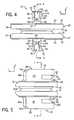
- FIG. 4is a front elevation view of the implant illustrated in FIG. 2 ;
- FIG. 5is a side elevation view of the implant illustrated in FIG. 2 ;
- FIG. 6is a cross-sectional view of the implant illustrated in FIG. 4 , taken along line 6 - 6
- FIG. 7is a cross-sectional view of the implant illustrated in FIG. 5 , taken along line 7 - 7 ;
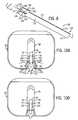
- FIG. 8is a perspective view of a forked osteotome instrument, constructed in accordance with one embodiment
- FIGS. 9A-Bare perspective views of the forked osteotome instrument illustrated in FIG. 8 coupled to the first implant endplate illustrated in FIG. 2 ;
- FIG. 10Ais a top plan view of an intervertebral implant including a pair of endplates constructed in accordance with an alternative embodiment, showing the coupling of an osteotome instrument constructed in accordance with an alternative embodiment to one of the endplates;
- FIG. 10Bis a top plan view of the intervertebral implant illustrated in FIG. 10A , showing the osteotome instrument coupled to the endplate;
- FIG. 11Ais a perspective view of an intervertebral implant constructed in accordance with another alternative embodiment
- FIG. 11Bis a top plan view the intervertebral implant illustrated in FIG. 11A ;
- FIG. 12Ais a perspective view of an intervertebral implant constructed in accordance with yet another alternative embodiment.
- FIG. 12Bis a top plan view the intervertebral implant illustrated in FIG. 12A .
- a pair of adjacent vertebral bodies 12including a superior vertebral body 12 a and an inferior vertebral body 12 b , defines an intervertebral space 14 disposed therebetween.
- the intervertebral space 14is illustrated after a discectomy, whereby the disc material has been removed to prepare the intervertebral space 14 to receive an implant, such as the intervertebral implant 10 illustrated in FIG. 2 .
- the implant 10is configured to be inserted into the intervertebral space 14 , and achieve improved stability between the vertebral bodies 12 (for fusion or non-fusion procedures).
- the intervertebral space 14can be disposed anywhere along the spine, but is disposed in the cervical region of the spine in accordance with one embodiment.
- the implant 10 and various components of the implantare described herein extending horizontally along a longitudinal direction “L” and lateral direction “A”, and vertically along a transverse direction “T”. Unless otherwise specified herein, the terms “lateral,” “longitudinal,” and “transverse” are used to describe the orthogonal directional components of various components.
- the longitudinal direction Lextends in an anterior-posterior direction
- the lateral direction Aextends in a medial-lateral direction
- the transverse direction Textends in a caudal-cranial direction. It should be appreciated, however, that the various directions defined by the implant 10 could alternatively be oriented at any desirable angle between 0° and 180° with respect to the medial-lateral and anterior-posterior directions and the transverse direction.
- the implant 10generally includes a first, or upper, endplate 20 and a second, or lower, endplate 22 .
- the endplates 20 and 22can be formed from a variety of biocompatible materials, such as cobalt chromium molybdenum (CoCrMo) with a porous plasma-sprayed titanium coating, titanium, stainless steel, ceramics, or polymers such as polyetheretherketone (PEEK).
- the endplates 20 and 22define substantially planar outer transverse bone-contacting surfaces 24 and 26 , respectively, and respective flexible keels 28 and 30 extending transversely out from the surfaces 24 and 26 .
- the keels 28 and 30are perpendicular with respect to the surfaces 24 and 26 .
- the surfaces 24 and 26can be smooth or textured to facilitate fusion with the associated vertebral body 12 .
- the implant 10defines a longitudinally forward end 11 and a longitudinally rear end 13 with respect to the direction of insertion of the implant 10 into the intervertebral space 14 .
- the implant 10is configured to be inserted into the intervertebral space 14 along the forward longitudinal direction that extends from the rear end 13 toward the front end 11 .
- the terms “forward” and “rearward” and derivatives thereof, as used herein with respect to the components of the implant 10are used reference to the forward and rear ends 11 and 13 of the implant 10 .
- a cutis made in the inferior as well as in the superior vertebral bodies 12 to provide keel cuts or slots 18 that extend therein that conform generally to the size and shape of the keels 28 and 30 .
- the keel cuts or slots 18can be provided using any method and apparatus as desired, such as a chisel or a drilling/milling system of the type disclosed in U.S. patent application Ser. No. 12/375,710, filed Jan. 30, 2009, the disclosure of which is hereby incorporated by reference as if set forth in its entirety herein. It should be appreciated that the slots 18 are formed in vertebral bodies 12 a - b , the slots can alternatively be disposed in boney tissue associated with any bone in the human body as desired, unless otherwise indicated.
- the implant 10can further include a plastic insert, or inlay 116 connected to the lower endplate 22 and disposed between the lower endplate 22 and the upper endplate 20 .
- the implant 10can define a width extending along the lateral direction A that can be between approximately 15-19 mm, a length extending along the longitudinal dimension L that can be approximately 12-16 mm, and a height extending between the outer surfaces 24 and 26 along the transverse direction T that can be approximately 5-9 mm.
- the implant 10is suitable for implantation in an intervertebral space in the cervical region of the spine, which is characterized by the need for precision because of the relatively small dimensions of cervical intervertebral spaces.
- the dimensions described above with respect to the implant 10 in the illustrated embodimentare in contrast to the dimensions of the implant 10 if the implant were to be inserted into an intervertebral space in the a different spinal region, for instance the lumbar region.
- the implant 10 configured for implantation into the lumbar regioncan have a width between approximately 27 and 30 mm, a length of approximately 34-39 mm, and a height of approximately 10-14 mm.
- the implant 10can be constructed with any dimensions desirable for implantation of any intervertebral space along the spine, and is not limited to the cervical and lumbar regions unless otherwise indicated.
- the implant 100is configured as a total disc replacement device, implants constructed in accordance with the teachings described herein are readily configurable for use with a range of bone-anchored orthopedic prostheses, such as interbody spacers, hip and knee replacement implants, and the like.
- the first endplate 20will now be described with particular reference to FIGS. 2A-5 . It should be appreciated that the directions “transversely in” and “transversely out” and derivatives thereof are used with respect to the first endplate 20 to describe upward and lower directions, respectively, when the endplate 20 is provided as an upper endplate as illustrated.
- the upper endplate 20defines the outer surface 24 that engages and supports the superior vertebral body 12 a .
- the outer surface 24is bound by edges 32 that are slightly beveled all the way around with the largest portion of the bevel being at the forward end 11 of the implant 10 .
- the endplate 20includes a peripheral side wall 34 that projects transversely in from the beveled edges 32 , and an inner transverse surface 36 positioned such that the side wall 34 extends between the outer surface 24 and the inner surface 36 .
- the keel 28can be integrally connected to the outer surface 24 of the upper endplate 20 , and sized and configured to be inserted into the slot 18 formed in one of the vertebral bodies 12 , such as the superior vertebral body 12 a .
- the keel 28can be construed as an anchoring keel configured to be disposed in the slot 18 .
- the slot 18can be pre-formed in the manner described above, or can be cut while inserting the keel 28 into the vertebral body.
- the endplate 20is illustrated as being associated with the superior vertebral body 12 a
- the lower endplate 22is described as being associated with the inferior vertebral body 12 b
- the endplate 20can alternatively be attached to the inferior vertebral body 12 b
- the lower endplate 22can alternatively be attached to the superior vertebral body 12 a , depending on the orientation of the implant 10 .
- the keel 28defines a proximal end 38 disposed proximate to the forward end 11 of the implant 10 , and a distal end 40 disposed proximate to the rear end 13 of the implant 10 .
- the keel 28includes a keel body 42 and a base 44 .
- the keel body 42is spaced transversely out from the outer surface 24 .
- the keel body 42extends transversely out from a base 44 that is integrally connected to, and extends transversely out from, the outer surface 24 .
- the keel body 42defines a pair of opposing side walls 43 that extend transversely out from the base 44 , and can be co-planar with opposing side walls 45 of the base 44 .
- the base 44further includes a distal engagement surface 47 that extends transversely out from the outer transverse surface 24 , and extends laterally between the distal, or rear, ends of the side walls 45 .
- the proximal end of the keel 28includes a pair of v-shaped upper bevels 46 a - b and a pair of v-shaped vertical beveled surfaces 48 a - b extending transversely in from the upper bevels 46 a - b .
- the bevels 46 a and 48 aare spaced from each other by the bevels 46 b and 48 b by a substantially flat, laterally extending, front surface 50 .
- the bevels 46 , 48 , and the front surface 50define a front keel profile that is substantially “arrow” shaped. The “arrow” shape facilitates insertion of the keel 28 into the slot 18 formed in the corresponding vertebral body 12 a.
- a first aperture 52extends transversely into the distal end of the keel body 42 and terminates at the base 44 .
- the aperture 52is longitudinally elongated, and extends distally through the body 42 , such that the distal end of the body 42 is open.
- the aperture 52defines a first wing 54 and a second wing 56 of the keel 28 .
- the first and second wings 54 and 56extend rearward from the keel body 42 .
- the second wing 56is laterally spaced from the first wing 54 via the aperture 52 .
- the wings 54 and 56are laterally spaced from each other by the aperture 52 , which provides a void that separates the wings 54 and 56 .
- Each wing 54 and 56can be flexible as illustrated and configured to move with respect to the outer transverse surface 24 .
- each wing 54 and 56terminates at its distal end at a first flexible flared distal region 58 and a second flexible flared distal region 60 , respectively.
- the flared regions 58 and 60project laterally outward with respect to the side walls 43 in a distal, or rearward, direction along the flared regions 58 and 60 .
- a channel 62extends longitudinally forward from the distal end of the keel 28 at a location transversely between the base 44 and the wings 54 and 56 .
- the channel 62extends longitudinally into, but not longitudinally through, the keel 28 and terminates at a distance that is distal with respect to the longitudinal boundary of the aperture 52 .
- the channel 62further extends laterally through the keel 28 . Accordingly, the wings 54 and 56 , including the flared regions 58 and 60 , are transversely spaced from the base 44 and the outer transverse surface 24 by channel 62 .
- the channel 62thus defines a void that separates the wings 54 and 56 from the base 44 and the outer surface 24 .
- the wings 54 and 56are thus spaced from the base 44 , or suspended above the base 44 when the first endplate 20 engages the superior vertebral body 12 a , but could be suspended below the base 44 if the first endplate 20 engages the inferior vertebral body 12 b.
- the keel 28thus defines a pair of distally-facing surfaces 64 and 66 , respectively, extending transversely between the base 44 and the wings 54 and 56 . If desired, the engagement surfaces 64 and 66 can be curved along the transverse direction as illustrated.
- the keel 28can further include a an instrument engagement feature in the form of a recess 68 protruding transversely into the base 44 at a location between the wings 54 and 56 , such that the recess 68 is accessible through the aperture 52 .
- the second endplate 22will now be described with continuing reference to FIGS. 2A-5 . It should be appreciated that the directions “transversely in” and “transversely out” and derivatives thereof are used with respect to the second endplate 22 to describe lower and upper directions, respectively, when the endplate 22 is provided as a lower endplate as illustrated.
- the lower endplate 22defines the outer surface 26 that engages and supports the inferior vertebral body 12 b .
- the second endplate 22is constructed substantially as described with respect to the first endplate 20 , such that the structural features extending transversely out from the outer transverse surface 26 of the second endplate 22 are aligned with like structural features that extend transversely out from outer the transverse surface 24 of the first endplate 20 .
- the outer surface 26is bound by edges 70 that are slightly beveled all the way around with the largest portion of the bevel being at the forward end 11 of the implant 10 .
- the endplate 22includes a peripheral side wall 72 that projects transversely in from the beveled edges 70 , and an inner transverse surface 74 positioned such that the side wall 72 extends between the outer surface 26 and the inner surface 74 .
- the keel 30can be integrally connected to the outer surface 26 of the second endplate 22 , and sized and configured to be inserted into the slot 18 formed in one of the vertebral bodies 12 , such as the inferior vertebral body 12 b .
- the slot 18can be pre-formed in the manner described above, or can be cut while inserting the keel 30 into the vertebral body.
- the lower endplate 22is illustrated as being associated with the inferior vertebral body 12 b
- the upper endplate 20is described as being associated with the superior vertebral body 12 a
- the endplate 22can alternatively be attached to the superior vertebral body 12 a
- the upper endplate 20can alternatively be attached to the inferior vertebral body 12 b , depending on the orientation of the implant 10 .
- the keel 30defines a proximal end 76 disposed proximate to the forward end 11 of the implant 10 , and a distal end 78 disposed proximate to the rear end 13 of the implant 10 .
- the keel 30includes a keel body 80 spaced transversely out from the outer surface 26 .
- the keel body 80extends transversely out from a base 82 that is integrally connected to, and extends transversely out from, the outer surface 26 .
- the keel body 80defines a pair of opposing side walls 81 that extend out from the base 82 , and can be co-planar with opposing side walls 83 of the base 82 .
- the base 82further includes a distal engagement surface 85 that extends transversely out from the outer transverse surface 26 , and further extends laterally between the distal, or rear, ends of the side walls 83 .
- the proximal end 76 of the keel 30includes a pair of v-shaped upper bevels 84 a - b and a pair of v-shaped vertical beveled surfaces 86 a - b extending transversely in from the upper bevels 84 a - b .
- the bevels 84 a and 86 aare spaced by the bevels 84 b and 86 b by a substantially flat, laterally extending, front surface 88 .
- the bevels 84 , 86 , and the front surface 88define a front keel profile that is substantially “arrow” shaped. The “arrow” shape facilitates insertion of the keel 20 into the slot 18 formed in the corresponding vertebral body 12 b.
- a first aperture 90extends transversely into the distal end 78 of the keel body 80 and terminates at the base 82 .
- the aperture 90is longitudinally elongated, and extends distally through the body 80 , such that the distal end of the body 42 is open and defines a first wing 92 and a second wing 94 disposed at the distal end 78 of the keel 30 .
- the first and second wings 92 and 94extend rearward from the keel body 80 .
- the wings 92 and 94are laterally spaced from each other by the aperture 90 , which provides a void that separates the wings 92 and 94 .
- Each wing 92 and 94can be flexible as illustrated and configured to move with respect to the outer transverse surface 26 .
- each wing 92 and 94terminates at its distal end at a first flexible flared region 96 and a second flexible flared region 98 , respectively.
- the flared regions 96 and 98project laterally outward with respect to the side walls 81 in a distal, or rearward, direction along the flared regions 96 and 98 , respectively.
- a channel 100extends longitudinally forward from the distal end of the keel 30 at a location transversely between the base 82 and the wings 92 and 94 .
- the channel 100extends longitudinally into, but not longitudinally through, the keel 30 and terminates at a distance that is distal with respect to the longitudinal boundary of the aperture 90 .
- the channel 100further extends laterally through the keel 30 .
- the wings 92 and 94including the flared regions 96 and 98 , are spaced from the base 82 and the outer transverse surface 26 by the channel 100 .
- the channel 100thus defines a void that separates the wings 92 and 94 from the base 44 and the outer surface 24 .
- the wings 92 and 94are thus suspended below the base 82 when the second endplate 22 engages the inferior vertebral body 12 b , but could be suspended above the base 82 if the second endplate 22 engages the superior vertebral body 12 a.
- the keel 30thus defines a pair of distally-facing surfaces 102 and 104 , respectively, extending transversely between the base 82 and the wings 92 and 94 . If desired, the surfaces 102 and 104 can be curved along the transverse direction as illustrated.
- the keel 30can further include an instrument engagement feature in the form of a recess 106 protruding transversely into the base 82 at a location between the wings 92 and 94 , such that the recess 106 is accessible through the aperture 90 .
- the endplates 20 and 22are mated at a joint 106 that is provided as an articulating joint configured to pivot each endplate 20 and 22 relative to the other endplate universally about 360°.
- the joint 106can be constructed as described in U.S. patent application Ser. No. 11/669,273, the disclosure of which is hereby incorporated by reference as if set forth in its entirety herein, or in accordance with any suitable alternative embodiment.
- the endplates 20 and 22thus each include respective mating joint members 108 and 110 , respectively.
- the lower endplate 22includes a pair of C-shaped support members 112 that extend transversely inwardly from the inner surface 74 .
- the support members 112present laterally inwardly facing receiving channels 114 that are configured to receive a plastic inlay 116 .
- the inlay 116includes a base 118 having laterally outer ends 120 that are sized to fit inside the channels 114 .
- the inlay 116can be inserted into the channels 114 in a direction from the rear end 13 of the endplate 22 toward the front end 11 of the endplate 22 .
- the endplate 22can include a stop disposed at the front end 11 to prevent over-insertion of the inlay 116 .
- the inlay 116can include a snap-in projection 122 that engages a snap-in recess 124 extending into the inner transverse surface 74 so that the inlay 116 can snap into place to prevent inadvertent removal
- the inlay 116further includes a dome-shape upper surface 126 centrally disposed on the base 118 and extending transversely in from the base 118 .
- the first endplate 20includes a raised surface 128 extending transversely in from the inner surface 36 .
- the raised surface 128defines a dome-shaped recess 130 projecting therein that is contoured and configured to receive and mate with the dome-shaped upper surface 126 .
- the endplates 20 and 22are configured to pivot universally with respect to each other about a 360° range of motion.
- the implantcould include any alternatively constructed joint that enables relative motion between the endplates 20 and 22 in any direction, or that fixedly attaches the endplates 20 and 22 .
- the first endplate 20could carry the inlay 116
- the second endplate 22could carry a raised surface such as raised surface 128 that engages the inlay 116 .
- a forked osteotome instrument 132can be provided and configured to insert one or both of the endplates 20 and 22 into the intervertebral space 14 described above. Because the keels 28 and 30 are substantially identically constructed, the instrument 132 is described herein as engaging the keel 28 of the first endplate 20 , it being appreciated that the description applies to the engagement of the instrument with the second endplate 22 . In this regard, it should be further appreciated that a pair of instruments 132 can be provided to engage the upper and lower endplates 20 and 22 , or that a single instrument can be provided having a pair of transversely spaced arms 140 and 142 that are configured to engage the keels 28 and 30 of both endplates 20 and 22 , respectively.
- the instrument 132includes a shaft 134 that is elongated along a longitudinal axis L, and defines a proximal end 136 that defines a handle 137 , and an opposing distal end 138 .
- the instrumentfurther defines a first, or outer transverse, surface 119 , and a second, or inner transverse, surface 121 opposite the first surface 119 .
- the instrument 132includes a first arm 140 and a second arm 142 that extend distally from the shaft 134 .
- the arms 140 and 142are spaced laterally (or horizontally) by a gap 144 , such that the instrument defines a forked distal end 138 .
- Each arm 140 and 142can define a distal edge 146 and 148 , respectively, that is beveled or flared longitudinally rearward in the transverse direction.
- the distal edges 146 and 148are beveled in a transverse direction from the inner transverse surface 121 to the outer transverse surface 119 along the edges 146 and 148 from the distal end 138 toward the proximal end 136 .
- the beveled edges 146 and 148can assist when inserting the implant 10 into the intervertebral space 14 .
- the instrument 132defines longitudinally extending, and laterally opposing, inner guide surfaces 150 and 152 of the arms 140 and 142 , respectively, and an inner stop surface 154 that extends laterally between the arms 140 and 142 .
- the distal edges 146 and 148present laterally inner surfaces 147 and 149 , respectively, that are beveled or flared laterally outward with respect to the inner guide surfaces 150 and 152 along a longitudinal direction from the proximal end 136 toward the distal end 138 .
- the distal edges 146 and 148define a lateral width therebetween that is greater than the lateral width disposed between the inner guide surfaces 150 and 152 .
- the width disposed between the arms 140 and 142thus tapers outwardly, with respect to the longitudinal axis L, at the distal end 138 of the instrument 132 .
- the tapered widthfacilitates engagement of the instrument 132 with the endplate 20 .
- the gap 144has a lateral dimension substantially equal to, or slightly greater than, the lateral width that separates the opposing side walls 43 of the keel body 42 , and thus also has a lateral dimension substantially equal to, or slightly greater than, the lateral width that separates the opposing side walls 45 of the keel body 42 .
- the inner stop surface 154has a lateral dimension substantially equal to, or slightly greater than, the lateral width that separates the opposing side walls 43 of the keel body 42 , and thus also has a lateral dimension substantially equal to, or slightly greater than, the lateral width that separates the opposing side walls 45 of the keel body 42
- At least a portion of the instrument 132 that engages the keel 28defines a height that can be substantially equal to the transverse height of the base 44 , or the engagement surface 47 (or the transverse distance between the outer transverse surface 24 of the endplate 20 and the outer transverse surface of the base 44 or engagement surface 47 ).
- the heightcan be greater than or less than the height of the base 44 or engagement surface 47 , such that the arms 140 and 142 are configured to engage the keel 28 during operation.
- the height of the portion of the instrument 132 that engages the keelcan have a height that is substantially equal to, or slightly less than, the transverse distance between the base 44 and the wing 54 and 56 .
- the height of the portion of the instrument 132 that engages the keel 28can be configured to fit within the channel 62 .
- the inner stop surface 154can have a height greater than that of the channel 62 .
- the instrument 132engages the keel 28 of the endplate 20 in order to facilitate insertion of the endplate 20 into the intervertebral space 14 .
- the instrument 132is oriented such that the second surface 121 is positioned to rest against the outer transverse surface 24 of the endplate 20 .
- the instrument 132is positioned such that the gap 144 separating the arms 140 and 142 is aligned with the engagement surface 47 of the base 44 .
- the instrument 132can be oriented such that the inner transverse surface 121 is generally aligned with the engagement surface 47 .
- the instrument 132can then be translated with respect to the endplate 20 in the longitudinally forward direction indicated by arrow F, such that the gap 144 receives the base 44 therein.
- the beveled surfaces 147 and 149can correct any slight misalignments between the gap 144 and the base 44 during insertion.
- the inner surfaces 150 and 152 of the arms 140 and 142ride along the side walls 45 of the base 44 until the base 44 is captured between the arms 140 and 142 .
- the instrument 132is translated longitudinally forward to a fully mated position with the keel 28 , whereby the stop surface 154 abuts the engagement surface 47 .
- the engagement surface 47is configured to abut the stop surface 154 and receive a longitudinally forward biasing force from the stop surface 154 that biases the endplate in the longitudinally forward direction.
- the beveled edges 146 and 148flare transversely out from the outer transverse surface 24 , and thus assist when inserting the endplate 20 into the intervertebral space 14 .
- the beveled edges 146 and 148are disposed behind the beveled front edge 32 of the endplate 20 such that the bevel 32 first engages the intervertebral space, followed by the beveled edges 146 and 148 .
- the bevels 32 , 146 , and 148thus cooperate to facilitate insertion of the endplate 10 into the intervertebral space 14 .
- the wings 54 and 56including the first and second flared regions 58 and 60 , are inserted into the slot 18 formed in the vertebral body 12 a , such that the flared regions 58 and 60 of the wings 54 and 56 , respectively, engage the vertebral wall that defines the slot 18 . Because the aperture 52 separates the flared regions 58 and 60 , the flared regions 58 and 60 are flexible, and capable of flexing toward each other relative to the remainder of the endplate 20 . Thus, the flared regions 58 and 60 are capable of moving with respect to the bone contacting outer transverse surface 24 and the base 44 .
- the transverse inner edge of the flared regions 58 and 60are flexible with respect to the surface 24 and the base 44 .
- the inclusion of the flexible keel 28may reduce the insertion force necessary to implant a device featuring the keel 28 when compared to an implant featuring a conventional, nonflexible keel. Because the flared regions 58 and 60 of the wings 54 and 56 are spaced transversely out from the base 44 , interference between the insertion instrument 132 and the flared regions 58 is avoided as the endplate 20 is inserted into the intervertebral space 14 .
- a keel similar to the flexible keels 28 and 30 described abovecan alternatively be configured for use with interbody spacers or other orthopedic implants designed to be anchored to boney tissue.
- the alternate implantsmay then be revised and/or explanted using a similar method to those described above for the implant having the endplate 10 with the flexible keel 28 .
- the implant 10can be considered as an orthopedic implant.
- the endplate 20can be constructed in accordance with an alternative embodiment so as to facilitate easy removal of the endplate 20 from the intervertebral space 14 .
- the keel 28includes a pair of engagement walls 160 and 162 that extend laterally inward from respective laterally inner surfaces 57 and 59 of the wings 54 and 56 .
- the engagement walls 160 and 162present rear engagement surfaces 164 and 166 , respectively, that are angled longitudinally rearward from the inner surfaces 57 and 59 along a laterally inward direction along the surfaces 164 and 166 .
- a removal instrument 170includes a shaft 172 and a pair of laterally spaced arms 174 and 176 , respectively, each having a respective distal engagement surface 178 and 180 .
- Each engagement surface 178 and 180is angled longitudinally rearward along a laterally inward direction along the surfaces 178 and 180 .
- the engagement surfaces 178 and 180are configured to align and mate with the engagement surfaces 164 and 166 .
- the arms 174 and 176are rigid at least with respect to lateral movement, such that forward motion of the removal instrument 170 relative to the endplate 20 along the direction of Arrow F causes the engagement surfaces 170 and 180 to engage the engagement surfaces 164 and 166 . Continue forward movement causes the surfaces 164 and 166 to ride laterally inward along the engagement surfaces 170 and 180 .
- the engagement surfaces 170 and 180impart a laterally inward biasing force against the engagement surfaces 170 and 180 , and thus against the corresponding flared regions 58 and 60 of the wings 54 and 56 that causes the flared regions 58 and 60 to flex or retract laterally inward toward each other along the direction of Arrow I.
- the engagement surfaces 164 and 166are disposed between the flared regions 58 and 60 , and are configured to receive a force from an instrument that biases the flared regions 58 and 60 toward each other.
- the flared regions 58 and 60are configured to retract from a first outer position illustrated in FIG. 10A , whereby the regions 58 and 60 are configured to abut, and engage, the surfaces of the vertebral body 12 a that define the slot 18 , to a second inner position illustrated in FIG. 10B , whereby the flared regions 58 and 60 are flexed laterally inward away from, and thus disengaged from, the surfaces of the vertebral body 12 a that define the slot 18 . Accordingly, the flared regions 58 and 60 can be disengaged from the vertebral surfaces to facilitate revision and/or explantation of the endplate 20 .
- the second endplate 22can be constructed substantially as described above with respect to the endplate 20 . Accordingly, the second endplate can include engagement walls as described with respect to the engagement walls 160 and 162 extending from the laterally inner surfaces of the wings 92 and 94 in the manner described above.
- the keels 28 and 30have been described in accordance with certain embodiments, and that the keels 28 and 30 can be constructed in accordance with any alternative embodiment, such that at least one or both of the keels 28 and 30 includes a flexible and/or flared wing.
- the keel 28is illustrated in accordance with an alternative embodiment, it being appreciated that the keel 30 can be similarly constructed.
- the keel 28is constructed substantially as described above, however one of the wings (wing 54 as illustrated) extends longitudinally out from the keel body 42 , and thus defines a laterally outer surface 55 that is coplanar with the outer surface 43 of the keel body 42 along its entire longitudinal length.
- the distal region 58is not outwardly flared in the lateral direction, and in fact does not extend in a direction having a lateral component, but rather extends longitudinally rearward toward the distal end 13 .
- the opposing wing 56can include the flared region 60 in the manner described above.
- the keels 28 and 30is devoid of one of the distal regions of the wings, and is further devoid of an entire one of the wings.
- the keel 28is constructed substantially as described above, however the keel 28 is devoid of one of the wings (wing 54 as illustrated).
- the keel body 42can further be devoid of the entire lateral portion of the keel body 42 that would extend transversely out from the base 44 at a location on the same lateral side as the missing wing 54 with respect to a longitudinal axis L 1 that extends centrally through the endplate 20 .
- the opposing wing 56can include the flared region 60 in the manner described above.
- the keels 28 and 30 constructed in accordance with any of the embodiments described hereindefines a maximum lateral width defines as the lateral distance between opposing laterally outermost surfaces.
- the maximum lateral width of the keel 28extends laterally between the laterally outer surfaces of the flared regions 58 and 60 at the distal edges of the flared regions 58 and 60 .
- the maximum widthis illustrated as extending between the laterally outer surface of the flared region 60 at the distal edge of the flared region 60 and the laterally outer surface 55 of the wing 54 .
- FIGS. 11A-Bthe maximum width is illustrated as extending between the laterally outer surface of the flared region 60 at the distal edge of the flared region 60 and the laterally outer surface 55 of the wing 54 .
- the maximum widthis illustrated as extending between the laterally outer surface of the flared region 60 at the distal end of the flared region 60 and the laterally outer surface 43 of the keel body 42 .
- the maximum width of the keels 28 and 30 in each of the above-described embodimentscan be the same as, greater than, or less than, the maximum widths in any of the other embodiments. Accordingly, the keels 28 and 30 can fit into the same sized slot 28 , or differently sized slots as desired.
Landscapes
- Health & Medical Sciences (AREA)
- Engineering & Computer Science (AREA)
- Biomedical Technology (AREA)
- Orthopedic Medicine & Surgery (AREA)
- Transplantation (AREA)
- Neurology (AREA)
- Heart & Thoracic Surgery (AREA)
- Oral & Maxillofacial Surgery (AREA)
- Cardiology (AREA)
- Vascular Medicine (AREA)
- Life Sciences & Earth Sciences (AREA)
- Animal Behavior & Ethology (AREA)
- General Health & Medical Sciences (AREA)
- Public Health (AREA)
- Veterinary Medicine (AREA)
- Physical Education & Sports Medicine (AREA)
- Prostheses (AREA)
- Materials For Medical Uses (AREA)
Abstract
Description
Claims (22)
Priority Applications (1)
| Application Number | Priority Date | Filing Date | Title |
|---|---|---|---|
| US12/641,441US8425603B2 (en) | 2008-12-22 | 2009-12-18 | Orthopedic implant with flexible keel |
Applications Claiming Priority (2)
| Application Number | Priority Date | Filing Date | Title |
|---|---|---|---|
| US13996408P | 2008-12-22 | 2008-12-22 | |
| US12/641,441US8425603B2 (en) | 2008-12-22 | 2009-12-18 | Orthopedic implant with flexible keel |
Publications (2)
| Publication Number | Publication Date |
|---|---|
| US20100168860A1 US20100168860A1 (en) | 2010-07-01 |
| US8425603B2true US8425603B2 (en) | 2013-04-23 |
Family
ID=42072759
Family Applications (1)
| Application Number | Title | Priority Date | Filing Date |
|---|---|---|---|
| US12/641,441Active2031-04-15US8425603B2 (en) | 2008-12-22 | 2009-12-18 | Orthopedic implant with flexible keel |
Country Status (5)
| Country | Link |
|---|---|
| US (1) | US8425603B2 (en) |
| EP (1) | EP2376028B1 (en) |
| JP (1) | JP5681639B2 (en) |
| CA (1) | CA2747660A1 (en) |
| WO (1) | WO2010075195A1 (en) |
Cited By (15)
| Publication number | Priority date | Publication date | Assignee | Title |
|---|---|---|---|---|
| US20080027553A1 (en)* | 1997-01-02 | 2008-01-31 | Zucherman James F | Spine distraction implant and method |
| US8979928B2 (en) | 2010-01-13 | 2015-03-17 | Jcbd, Llc | Sacroiliac joint fixation fusion system |
| US9333090B2 (en) | 2010-01-13 | 2016-05-10 | Jcbd, Llc | Systems for and methods of fusing a sacroiliac joint |
| US9381045B2 (en) | 2010-01-13 | 2016-07-05 | Jcbd, Llc | Sacroiliac joint implant and sacroiliac joint instrument for fusing a sacroiliac joint |
| US9421109B2 (en) | 2010-01-13 | 2016-08-23 | Jcbd, Llc | Systems and methods of fusing a sacroiliac joint |
| US9554909B2 (en) | 2012-07-20 | 2017-01-31 | Jcbd, Llc | Orthopedic anchoring system and methods |
| US20170105850A1 (en)* | 2014-12-23 | 2017-04-20 | Globus Medical, Inc. | Vertebral implants and methods for installation thereof |
| US9700356B2 (en) | 2013-07-30 | 2017-07-11 | Jcbd, Llc | Systems for and methods of fusing a sacroiliac joint |
| US9717539B2 (en) | 2013-07-30 | 2017-08-01 | Jcbd, Llc | Implants, systems, and methods for fusing a sacroiliac joint |
| US9788961B2 (en) | 2010-01-13 | 2017-10-17 | Jcbd, Llc | Sacroiliac joint implant system |
| US9801546B2 (en) | 2014-05-27 | 2017-10-31 | Jcbd, Llc | Systems for and methods of diagnosing and treating a sacroiliac joint disorder |
| US9826986B2 (en) | 2013-07-30 | 2017-11-28 | Jcbd, Llc | Systems for and methods of preparing a sacroiliac joint for fusion |
| US20180064550A1 (en)* | 2003-07-31 | 2018-03-08 | Globus Medical, Inc. | Prosthetic spinal disc replacement and methods thereof |
| US10245087B2 (en) | 2013-03-15 | 2019-04-02 | Jcbd, Llc | Systems and methods for fusing a sacroiliac joint and anchoring an orthopedic appliance |
| US10603055B2 (en) | 2017-09-15 | 2020-03-31 | Jcbd, Llc | Systems for and methods of preparing and fusing a sacroiliac joint |
Families Citing this family (4)
| Publication number | Priority date | Publication date | Assignee | Title |
|---|---|---|---|---|
| FR2858546B1 (en) | 2003-08-04 | 2006-04-28 | Spine Next Sa | INTERVERTEBRAL DISC PROSTHESIS |
| US8496713B2 (en)* | 2010-12-10 | 2013-07-30 | Globus Medical, Inc. | Spine stabilization device and methods |
| US8998991B2 (en)* | 2011-02-23 | 2015-04-07 | Globus Medical, Inc. | Six degree spine stabilization devices and methods |
| US9125753B2 (en) | 2012-02-17 | 2015-09-08 | Ervin Caballes | Elastomeric artificial joints and intervertebral prosthesis systems |
Citations (196)
| Publication number | Priority date | Publication date | Assignee | Title |
|---|---|---|---|---|
| US114816A (en) | 1871-05-16 | Improvement in carriage-jacks | ||
| US3486505A (en) | 1967-05-22 | 1969-12-30 | Gordon M Morrison | Orthopedic surgical instrument |
| US3579829A (en) | 1970-01-22 | 1971-05-25 | Sampson Corp | Pericortical dental implant and inserter therefor |
| DE2263842A1 (en) | 1972-12-28 | 1974-07-04 | Hoffmann Daimler Siegfried Dr | DISC PROTHESIS |
| US3875595A (en) | 1974-04-15 | 1975-04-08 | Edward C Froning | Intervertebral disc prosthesis and instruments for locating same |
| US4021864A (en) | 1976-04-14 | 1977-05-10 | The Regents Of The University Of California | Ankle prosthesis |
| US4034746A (en) | 1975-08-01 | 1977-07-12 | Williams Robert W | Retractor |
| US4038987A (en) | 1974-02-08 | 1977-08-02 | Olympus Optical Co., Ltd. | Forceps device for endoscope |
| US4038897A (en) | 1975-10-14 | 1977-08-02 | Electronic Music Laboratories, Inc. | Electronic music system and stringed instrument input device therefor |
| DE2804936A1 (en) | 1978-02-01 | 1979-08-02 | Sulzer Ag | INTER-SPINE PROSTHESIS |
| US4232404A (en) | 1977-07-18 | 1980-11-11 | National Research Development Corporation | Endoprosthetic ankle joint |
| US4309777A (en) | 1980-11-13 | 1982-01-12 | Patil Arun A | Artificial intervertebral disc |
| DE3023353C2 (en) | 1979-10-03 | 1982-04-22 | Gebrüder Sulzer AG, 8401 Winterthur | Total intervertebral prosthesis |
| US4349921A (en) | 1980-06-13 | 1982-09-21 | Kuntz J David | Intervertebral disc prosthesis |
| EP0077159A1 (en) | 1981-10-14 | 1983-04-20 | Brian Norman Atkins | Vertebrae spreader |
| US4467802A (en) | 1980-03-31 | 1984-08-28 | Harald Maslanka | Surgical gripping instrument |
| US4470158A (en) | 1978-03-10 | 1984-09-11 | Biomedical Engineering Corp. | Joint endoprosthesis |
| US4545374A (en) | 1982-09-03 | 1985-10-08 | Jacobson Robert E | Method and instruments for performing a percutaneous lumbar diskectomy |
| DE3526742A1 (en) | 1985-07-26 | 1987-01-29 | Volkmar Dipl Ing Jansson | Guide sleeve with a striker for driving (bone) chips in bone |
| US4697586A (en) | 1986-06-24 | 1987-10-06 | Gazale William J | Combined chisel-guide surgical instrument |
| US4714469A (en) | 1987-02-26 | 1987-12-22 | Pfizer Hospital Products Group, Inc. | Spinal implant |
| US4736738A (en) | 1984-07-09 | 1988-04-12 | Matej Lipovsek | Instrument kit and procedure for performing posterior lumbar interbody fusion |
| US4759769A (en) | 1987-02-12 | 1988-07-26 | Health & Research Services Inc. | Artificial spinal disc |
| US4759766A (en) | 1984-09-04 | 1988-07-26 | Humboldt-Universitaet Zu Berlin | Intervertebral disc endoprosthesis |
| US4863476A (en) | 1986-08-29 | 1989-09-05 | Shepperd John A N | Spinal implant |
| EP0333990A2 (en) | 1988-03-23 | 1989-09-27 | Waldemar Link (GmbH & Co.) | Surgical instrument set |
| US4874389A (en) | 1987-12-07 | 1989-10-17 | Downey Ernest L | Replacement disc |
| US4892545A (en) | 1988-07-14 | 1990-01-09 | Ohio Medical Instrument Company, Inc. | Vertebral lock |
| US4898161A (en) | 1986-12-05 | 1990-02-06 | S+G Implants Gmbh | Forceps for pushing apart vertebrae |
| US4932975A (en) | 1989-10-16 | 1990-06-12 | Vanderbilt University | Vertebral prosthesis |
| US4946378A (en) | 1987-11-24 | 1990-08-07 | Asahi Kogaku Kogyo Kabushiki Kaisha | Artificial intervertebral disc |
| US5002576A (en) | 1988-06-06 | 1991-03-26 | Mecron Medizinische Produkte Gmbh | Intervertebral disk endoprosthesis |
| US5037438A (en) | 1989-07-25 | 1991-08-06 | Richards Medical Company | Zirconium oxide coated prosthesis for wear and corrosion resistance |
| WO1991013598A1 (en) | 1990-03-07 | 1991-09-19 | J.B.S. S.A. | Prosthesis for intervertebral discs and instruments for its implantation |
| US5062850A (en) | 1990-01-16 | 1991-11-05 | University Of Florida | Axially-fixed vertebral body prosthesis and method of fixation |
| US5071437A (en) | 1989-02-15 | 1991-12-10 | Acromed Corporation | Artificial disc |
| US5108442A (en) | 1991-05-09 | 1992-04-28 | Boehringer Mannheim Corporation | Prosthetic implant locking assembly |
| US5171280A (en) | 1990-04-20 | 1992-12-15 | Sulzer Brothers Limited | Intervertebral prosthesis |
| US5192327A (en) | 1991-03-22 | 1993-03-09 | Brantigan John W | Surgical prosthetic implant for vertebrae |
| US5211645A (en) | 1989-07-04 | 1993-05-18 | Rainer Baumgart | Device for guiding an internal saw for long tubular bone osteotomy |
| US5228455A (en) | 1991-05-20 | 1993-07-20 | Siemens Pacesetter, Inc. | Implant tool for extendable/retractable positive fixation lead |
| US5236460A (en) | 1990-02-12 | 1993-08-17 | Midas Rex Pneumatic Tools, Inc. | Vertebral body prosthesis |
| US5258031A (en) | 1992-01-06 | 1993-11-02 | Danek Medical | Intervertebral disk arthroplasty |
| US5271737A (en) | 1992-09-04 | 1993-12-21 | U.S. Medical Products, Inc. | Tibial prosthetic implant with offset stem |
| US5290312A (en) | 1991-09-03 | 1994-03-01 | Alphatec | Artificial vertebral body |
| US5306308A (en) | 1989-10-23 | 1994-04-26 | Ulrich Gross | Intervertebral implant |
| US5306309A (en) | 1992-05-04 | 1994-04-26 | Calcitek, Inc. | Spinal disk implant and implantation kit |
| US5336232A (en) | 1991-03-14 | 1994-08-09 | United States Surgical Corporation | Approximating apparatus for surgical jaw structure and method of using the same |
| US5344458A (en) | 1992-08-06 | 1994-09-06 | Bonutti Peter M | Arthroplasty component |
| US5364397A (en) | 1993-06-01 | 1994-11-15 | Zimmer, Inc. | Spinal coupler seater with dual jaws and an independent plunger |
| US5370697A (en) | 1992-04-21 | 1994-12-06 | Sulzer Medizinaltechnik Ag | Artificial intervertebral disk member |
| US5383888A (en) | 1992-02-12 | 1995-01-24 | United States Surgical Corporation | Articulating endoscopic surgical apparatus |
| US5395317A (en) | 1991-10-30 | 1995-03-07 | Smith & Nephew Dyonics, Inc. | Unilateral biportal percutaneous surgical procedure |
| US5401269A (en) | 1992-03-13 | 1995-03-28 | Waldemar Link Gmbh & Co. | Intervertebral disc endoprosthesis |
| US5409492A (en) | 1993-08-09 | 1995-04-25 | Stelkast Incorporated | System for coupling an implant to a tool for inserting and removing the implant |
| US5423825A (en) | 1992-06-10 | 1995-06-13 | Levine; Andrew S. | Spinal fusion instruments and methods |
| US5425773A (en) | 1992-01-06 | 1995-06-20 | Danek Medical, Inc. | Intervertebral disk arthroplasty device |
| US5431658A (en) | 1994-02-14 | 1995-07-11 | Moskovich; Ronald | Facilitator for vertebrae grafts and prostheses |
| US5443514A (en) | 1993-10-01 | 1995-08-22 | Acromed Corporation | Method for using spinal implants |
| US5484437A (en) | 1988-06-13 | 1996-01-16 | Michelson; Gary K. | Apparatus and method of inserting spinal implants |
| US5489307A (en) | 1993-02-10 | 1996-02-06 | Spine-Tech, Inc. | Spinal stabilization surgical method |
| US5501654A (en) | 1993-07-15 | 1996-03-26 | Ethicon, Inc. | Endoscopic instrument having articulating element |
| US5507816A (en) | 1991-12-04 | 1996-04-16 | Customflex Limited | Spinal vertebrae implants |
| US5509934A (en) | 1992-02-28 | 1996-04-23 | Osteonics Corp. | Prosthetic knee tibial component constructed of synthetic polymeric material |
| US5534029A (en) | 1992-12-14 | 1996-07-09 | Yumiko Shima | Articulated vertebral body spacer |
| US5534030A (en) | 1993-02-09 | 1996-07-09 | Acromed Corporation | Spine disc |
| US5545229A (en) | 1988-08-18 | 1996-08-13 | University Of Medicine And Dentistry Of Nj | Functional and biocompatible intervertebral disc spacer containing elastomeric material of varying hardness |
| US5554191A (en) | 1994-01-26 | 1996-09-10 | Biomat | Intersomatic vertebral cage |
| US5556431A (en) | 1992-03-13 | 1996-09-17 | B+E,Uml U+Ee Ttner-Janz; Karin | Intervertebral disc endoprosthesis |
| US5562736A (en) | 1994-10-17 | 1996-10-08 | Raymedica, Inc. | Method for surgical implantation of a prosthetic spinal disc nucleus |
| US5571109A (en) | 1993-08-26 | 1996-11-05 | Man Ceramics Gmbh | System for the immobilization of vertebrae |
| US5591235A (en) | 1995-03-15 | 1997-01-07 | Kuslich; Stephen D. | Spinal fixation device |
| FR2724108B1 (en) | 1994-09-02 | 1997-01-17 | Jbs Sa | JOINT PROSTHESIS |
| US5609636A (en) | 1994-05-23 | 1997-03-11 | Spine-Tech, Inc. | Spinal implant |
| US5676701A (en) | 1993-01-14 | 1997-10-14 | Smith & Nephew, Inc. | Low wear artificial spinal disc |
| FR2737656B1 (en) | 1995-08-09 | 1997-10-17 | Jbs Sa | IMPACTOR DEVICE FOR PLACING A PROSTHESIS FOR INTERVERTEBRAL DISCS |
| US5683465A (en) | 1996-03-18 | 1997-11-04 | Shinn; Gary Lee | Artificial intervertebral disk prosthesis |
| US5702469A (en) | 1996-01-18 | 1997-12-30 | Kinetikos Medical, Inc. | Thumb joint prosthesis and related method of implantation |
| US5716415A (en) | 1993-10-01 | 1998-02-10 | Acromed Corporation | Spinal implant |
| US5720751A (en) | 1996-11-27 | 1998-02-24 | Jackson; Roger P. | Tools for use in seating spinal rods in open ended implants |
| FR2742653B1 (en) | 1995-12-21 | 1998-02-27 | Colorado | INTERSOMATIC VERTEBRAL CAGE |
| US5722977A (en) | 1996-01-24 | 1998-03-03 | Danek Medical, Inc. | Method and means for anterior lumbar exact cut with quadrilateral osteotome and precision guide/spacer |
| US5776199A (en) | 1988-06-28 | 1998-07-07 | Sofamor Danek Properties | Artificial spinal fusion implants |
| US5782830A (en) | 1995-10-16 | 1998-07-21 | Sdgi Holdings, Inc. | Implant insertion device |
| US5782832A (en) | 1996-10-01 | 1998-07-21 | Surgical Dynamics, Inc. | Spinal fusion implant and method of insertion thereof |
| WO1998034552A1 (en) | 1997-02-06 | 1998-08-13 | Surgical Dynamics | Expandable non-threaded spinal fusion device |
| US5797909A (en) | 1988-06-13 | 1998-08-25 | Michelson; Gary Karlin | Apparatus for inserting spinal implants |
| US5800547A (en) | 1994-08-20 | 1998-09-01 | Schafer Micomed Gmbh | Ventral intervertebral implant |
| US5824094A (en) | 1997-10-17 | 1998-10-20 | Acromed Corporation | Spinal disc |
| USD401335S (en) | 1997-07-28 | 1998-11-17 | Tibor Koros | Combined cervical and lumbar extractor and injector surgical instrument |
| US5865848A (en) | 1997-09-12 | 1999-02-02 | Artifex, Ltd. | Dynamic intervertebral spacer and method of use |
| US5885300A (en) | 1996-04-01 | 1999-03-23 | Asahi Kogaku Kogyo Kabushiki Kaisha | Guide apparatus of intervertebral implant |
| US5888226A (en) | 1997-11-12 | 1999-03-30 | Rogozinski; Chaim | Intervertebral prosthetic disc |
| US5895428A (en) | 1996-11-01 | 1999-04-20 | Berry; Don | Load bearing spinal joint implant |
| US5897593A (en) | 1997-03-06 | 1999-04-27 | Sulzer Spine-Tech Inc. | Lordotic spinal implant |
| US5899901A (en) | 1991-05-18 | 1999-05-04 | Middleton; Jeffrey Keith | Spinal fixation system |
| US5899941A (en) | 1997-12-09 | 1999-05-04 | Chubu Bearing Kabushiki Kaisha | Artificial intervertebral disk |
| US5951564A (en) | 1996-12-18 | 1999-09-14 | Bristol-Myers Squibb Company | Orthopaedic positioning apparatus |
| DE29916078U1 (en) | 1999-09-14 | 1999-11-25 | Aesculap Ag & Co Kg | Insertion tool for an intervertebral implant |
| US6006174A (en) | 1990-10-03 | 1999-12-21 | Interdigital Technology Coporation | Multiple impulse excitation speech encoder and decoder |
| US6010502A (en) | 1995-12-19 | 2000-01-04 | Spine-Tech, Inc. | Method and apparatus for conjoining bone bodies |
| US6017342A (en) | 1998-08-05 | 2000-01-25 | Beere Precision Medical Instrumnets, Inc. | Compression and distraction instrument |
| US6019792A (en) | 1998-04-23 | 2000-02-01 | Cauthen Research Group, Inc. | Articulating spinal implant |
| US6033405A (en) | 1994-09-15 | 2000-03-07 | Surgical Dynamics, Inc. | Apparatus and method for implant insertion |
| US6036692A (en) | 1997-02-12 | 2000-03-14 | Sdgi Holdings, Inc. | Rod introducer forceps |
| US6042582A (en) | 1997-05-20 | 2000-03-28 | Ray; Charles D. | Instrumentation and method for facilitating insertion of spinal implant |
| US6059790A (en) | 1997-08-29 | 2000-05-09 | Sulzer Spine-Tech Inc. | Apparatus and method for spinal stabilization |
| US6063088A (en) | 1997-03-24 | 2000-05-16 | United States Surgical Corporation | Method and instrumentation for implant insertion |
| US6063121A (en) | 1998-07-29 | 2000-05-16 | Xavier; Ravi | Vertebral body prosthesis |
| US6083225A (en) | 1996-03-14 | 2000-07-04 | Surgical Dynamics, Inc. | Method and instrumentation for implant insertion |
| US6086595A (en) | 1997-08-29 | 2000-07-11 | Sulzer Spine-Tech Inc. | Apparatus and method for spinal stabilization |
| US6096080A (en) | 1998-05-06 | 2000-08-01 | Cortek, Inc. | Apparatus for spinal fusion using implanted devices |
| US6102954A (en) | 1992-05-18 | 2000-08-15 | Astra Aktiebolag | Joint prosthesis and apparatus for preparing the bone prior to fitting of the prosthesis |
| US6102950A (en) | 1999-01-19 | 2000-08-15 | Vaccaro; Alex | Intervertebral body fusion device |
| US6110179A (en) | 1998-03-02 | 2000-08-29 | Benoist Girard Sas | Prosthesis inserter |
| US6113638A (en) | 1999-02-26 | 2000-09-05 | Williams; Lytton A. | Method and apparatus for intervertebral implant anchorage |
| US6113637A (en) | 1998-10-22 | 2000-09-05 | Sofamor Danek Holdings, Inc. | Artificial intervertebral joint permitting translational and rotational motion |
| US6113602A (en) | 1999-03-26 | 2000-09-05 | Sulzer Spine-Tech Inc. | Posterior spinal instrument guide and method |
| US6117174A (en) | 1998-09-16 | 2000-09-12 | Nolan; Wesley A. | Spinal implant device |
| US6126660A (en) | 1998-07-29 | 2000-10-03 | Sofamor Danek Holdings, Inc. | Spinal compression and distraction devices and surgical methods |
| US6126674A (en) | 1997-11-03 | 2000-10-03 | Mediplus Instruments Gmbh U. Co. Kg | Surgical sliding shaft instrument |
| US6146421A (en) | 1997-08-04 | 2000-11-14 | Gordon, Maya, Roberts And Thomas, Number 1, Llc | Multiple axis intervertebral prosthesis |
| US6156067A (en) | 1994-11-14 | 2000-12-05 | Spinal Dynamics Corporation | Human spinal disc prosthesis |
| US6159215A (en) | 1997-12-19 | 2000-12-12 | Depuy Acromed, Inc. | Insertion instruments and method for delivering a vertebral body spacer |
| US6171339B1 (en) | 1998-05-19 | 2001-01-09 | Sulzer Spine-Tech Inc. | Multi-lumen spinal implant guide and method |
| FR2795945A1 (en) | 1999-07-09 | 2001-01-12 | Scient X | ANATOMIC INTERSOMATIC IMPLANT AND GRIPPING FORCE FOR SUCH AN IMPLANT |
| US6174311B1 (en) | 1998-10-28 | 2001-01-16 | Sdgi Holdings, Inc. | Interbody fusion grafts and instrumentation |
| US6224599B1 (en) | 1999-05-19 | 2001-05-01 | Matthew G. Baynham | Viewable wedge distractor device |
| US6238414B1 (en) | 2000-01-20 | 2001-05-29 | Jerry R. Griffiths | Laparoscopic instrument with parallel actuated jaws |
| US6251140B1 (en) | 1998-05-27 | 2001-06-26 | Nuvasive, Inc. | Interlocking spinal inserts |
| US6261296B1 (en) | 1998-10-02 | 2001-07-17 | Synthes U.S.A. | Spinal disc space distractor |
| US6264655B1 (en) | 1995-06-07 | 2001-07-24 | Madhavan Pisharodi | Cervical disk and spinal stabilizer |
| US6309421B1 (en) | 1994-03-18 | 2001-10-30 | Madhavan Pisharodi | Rotating, locking intervertebral disk stabilizer and applicator |
| EP0712607B1 (en) | 1988-06-13 | 2002-02-27 | MICHELSON, Gary Karlin | Apparatus for use in spinal surgery |
| US6368351B1 (en) | 2001-03-27 | 2002-04-09 | Bradley J. Glenn | Intervertebral space implant for use in spinal fusion procedures |
| US6368350B1 (en) | 1999-03-11 | 2002-04-09 | Sulzer Spine-Tech Inc. | Intervertebral disc prosthesis and method |
| US6402785B1 (en) | 1999-06-04 | 2002-06-11 | Sdgi Holdings, Inc. | Artificial disc implant |
| US6413278B1 (en) | 1998-03-30 | 2002-07-02 | J. Alexander Marchosky | Prosthetic system |
| US6436139B1 (en) | 1999-02-04 | 2002-08-20 | Sdgi Holdings, Inc. | Interbody fusion device with anti-rotation features |
| US6440142B1 (en) | 2001-04-27 | 2002-08-27 | Third Millennium Engineering, Llc | Femoral ring loader |
| US6440169B1 (en) | 1998-02-10 | 2002-08-27 | Dimso | Interspinous stabilizer to be fixed to spinous processes of two vertebrae |
| WO2002071986A2 (en) | 2001-03-13 | 2002-09-19 | Depuy International Ltd. | Vertebral body replacement device |
| US6478801B1 (en) | 2001-07-16 | 2002-11-12 | Third Millennium Engineering, Llc | Insertion tool for use with tapered trial intervertebral distraction spacers |
| US6478800B1 (en) | 2000-05-08 | 2002-11-12 | Depuy Acromed, Inc. | Medical installation tool |
| US6500206B1 (en) | 2000-09-15 | 2002-12-31 | Donald W. Bryan | Instruments for inserting spinal vertebral implant |
| US6517544B1 (en) | 1998-06-09 | 2003-02-11 | Gary K. Michelson | Device and method for preparing a space between adjacent vertebrae to receive an insert |
| US20030083747A1 (en) | 2001-10-30 | 2003-05-01 | Osteotech, Inc. | Bone implant and isertion tools |
| US6558424B2 (en) | 2001-06-28 | 2003-05-06 | Depuy Acromed | Modular anatomic fusion device |
| US6565574B2 (en) | 1999-01-25 | 2003-05-20 | Gary K. Michelson | Distractor for use in spinal surgery |
| WO2003053290A1 (en) | 2001-12-12 | 2003-07-03 | Vita Special Purpose Corporation | Bioactive spinal implants and method of manufacture thereof |
| US20030135275A1 (en) | 2001-11-09 | 2003-07-17 | Javier Garcia | Instruments and methods for inserting a spinal implant |
| US6595995B2 (en) | 1995-03-27 | 2003-07-22 | Sdgi Holdings, Inc. | Methods and instruments for interbody fusion |
| US6599294B2 (en) | 1999-01-30 | 2003-07-29 | Aesculap Ag & Co. Kg | Surgical instrument for introducing intervertebral implants |
| US6613091B1 (en) | 1995-03-27 | 2003-09-02 | Sdgi Holdings, Inc. | Spinal fusion implants and tools for insertion and revision |
| US6635060B2 (en) | 2000-07-06 | 2003-10-21 | Sulzer Spine-Tech Inc. | Bone preparation instruments and methods |
| US6638310B2 (en) | 2000-07-26 | 2003-10-28 | Osteotech, Inc. | Intervertebral spacer and implant insertion instrumentation |
| US6641614B1 (en) | 1997-05-01 | 2003-11-04 | Spinal Concepts, Inc. | Multi-variable-height fusion device |
| US6652534B2 (en) | 1998-10-20 | 2003-11-25 | St. Francis Medical Technologies, Inc. | Apparatus and method for determining implant size |
| US6652533B2 (en) | 2001-09-20 | 2003-11-25 | Depuy Acromed, Inc. | Medical inserter tool with slaphammer |
| US20030233097A1 (en) | 2002-04-23 | 2003-12-18 | Ferree Bret A. | Artificial disc replacement (ADR) distraction sleeves and cutting guides |
| US20040030387A1 (en) | 2002-03-11 | 2004-02-12 | Landry Michael E. | Instrumentation and procedure for implanting spinal implant devices |
| US6719794B2 (en) | 2001-05-03 | 2004-04-13 | Synthes (U.S.A.) | Intervertebral implant for transforaminal posterior lumbar interbody fusion procedure |
| US6733505B2 (en) | 2000-04-26 | 2004-05-11 | Sdgi Holdings, Inc. | Apparatus and method for loading a prosthetic nucleus into a deployment cannula to replace the nucleus pulposus of an intervertebral disc |
| US6740118B2 (en) | 2002-01-09 | 2004-05-25 | Sdgi Holdings, Inc. | Intervertebral prosthetic joint |
| US6743256B2 (en) | 2000-10-11 | 2004-06-01 | Michael D. Mason | Graftless spinal fusion device |
| US6743257B2 (en) | 2000-12-19 | 2004-06-01 | Cortek, Inc. | Dynamic implanted intervertebral spacer |
| US6746454B2 (en) | 2000-11-07 | 2004-06-08 | Osteotech, Inc. | Implant insertion tool |
| US20040143332A1 (en) | 2002-10-31 | 2004-07-22 | Krueger David J. | Movable disc implant |
| US6770074B2 (en) | 1988-06-13 | 2004-08-03 | Gary Karlin Michelson | Apparatus for use in inserting spinal implants |
| US20040215198A1 (en) | 2003-04-28 | 2004-10-28 | Spine Solutions, Inc. | Instruments and method for preparing an intervertebral space for receiving an artificial disc implant |
| US20040225295A1 (en) | 2001-07-16 | 2004-11-11 | Rafail Zubok | Wedge ramp distractor and related methods for use in implanting artificial intervertebral discs |
| US6824565B2 (en) | 2000-09-08 | 2004-11-30 | Nabil L. Muhanna | System and methods for inserting a vertebral spacer |
| US20040260286A1 (en) | 1999-10-08 | 2004-12-23 | Ferree Bret A. | Intradiscal devices with anti-extrusion keels |
| US20050021042A1 (en) | 2003-07-21 | 2005-01-27 | Theirry Marnay | Instruments and method for inserting an intervertebral implant |
| US6875213B2 (en) | 1993-06-10 | 2005-04-05 | Sdgi Holdings, Inc. | Method of inserting spinal implants with the use of imaging |
| US20050085917A1 (en) | 1999-07-02 | 2005-04-21 | Thierry Marnay | Intervertebral implant |
| US6896676B2 (en) | 2003-03-06 | 2005-05-24 | Spinecore, Inc. | Instrumentation and methods for use in implanting a cervical disc replacement device |
| US20050143749A1 (en) | 2003-12-31 | 2005-06-30 | Depuy Spine, Inc. | Inserter instrument and implant clip |
| US20050165408A1 (en) | 2004-01-26 | 2005-07-28 | Puno Rolando M. | Methods and instrumentation for inserting intervertebral grafts and devices |
| US20050251260A1 (en) | 2002-08-15 | 2005-11-10 | David Gerber | Controlled artificial intervertebral disc implant |
| US20060030860A1 (en) | 2004-07-23 | 2006-02-09 | Sdgi Holdings, Inc. | Artificial disc inserter |
| US20060089656A1 (en) | 2004-10-22 | 2006-04-27 | Sdgi Holdings, Inc. | Revision instruments |
| US20060149273A1 (en) | 2004-12-06 | 2006-07-06 | Axiomed Spine Corporation | Method and apparatus for replacing a spinal disc |
| US7081120B2 (en) | 1999-04-26 | 2006-07-25 | Sdgi Holdings, Inc. | Instrumentation and method for delivering an implant into a vertebral space |
| US20060241641A1 (en) | 2005-04-22 | 2006-10-26 | Sdgi Holdings, Inc. | Methods and instrumentation for distraction and insertion of implants in a spinal disc space |
| US20070010826A1 (en) | 2003-07-31 | 2007-01-11 | Rhoda William S | Posterior prosthetic spinal disc replacement and methods thereof |
| US7169182B2 (en) | 2001-07-16 | 2007-01-30 | Spinecore, Inc. | Implanting an artificial intervertebral disc |
| US20070055378A1 (en)* | 2003-07-31 | 2007-03-08 | Ankney David W | Transforaminal prosthetic spinal disc replacement and methods thereof |
| US7189234B2 (en) | 1998-10-20 | 2007-03-13 | St. Francis Medical Technologies, Inc. | Interspinous process implant sizer and distractor with a split head and size indicator and method |
| US7204852B2 (en) | 2002-12-13 | 2007-04-17 | Spine Solutions, Inc. | Intervertebral implant, insertion tool and method of inserting same |
| US7252673B2 (en) | 2003-09-10 | 2007-08-07 | Warsaw Orthopedic, Inc. | Devices and methods for inserting spinal implants |
| US7547309B2 (en) | 2004-09-23 | 2009-06-16 | Spine Solutions, Inc. | Distractor for lumbar insertion instrument |
| US7625380B2 (en) | 2004-07-21 | 2009-12-01 | Warsaw Orthopedic, Inc. | Dual distractor inserter |
| US20100076443A1 (en) | 2006-07-31 | 2010-03-25 | Rudolph Bertagnoli | Drilling/milling guide and keel cut preparation system |
| US7763024B2 (en) | 2004-09-23 | 2010-07-27 | Spine Solutions, Inc. | Adjustable cutting of cutout in vertebral bone |
| US7905921B2 (en) | 2003-08-01 | 2011-03-15 | Spinal Kinetics, Inc. | Prosthetic intervertebral disc |
Family Cites Families (4)
| Publication number | Priority date | Publication date | Assignee | Title |
|---|---|---|---|---|
| US6742257B1 (en)* | 2001-10-02 | 2004-06-01 | Candescent Technologies Corporation | Method of forming powder metal phosphor matrix and gripper structures in wall support |
| US6957496B2 (en)* | 2002-02-14 | 2005-10-25 | Faro Technologies, Inc. | Method for improving measurement accuracy of a portable coordinate measurement machine |
| CA2495404C (en)* | 2002-08-15 | 2011-05-03 | Justin K. Coppes | Intervertebral disc implant |
| WO2007140382A2 (en) | 2006-05-26 | 2007-12-06 | Abdou M S | Inter-vertebral disc motion devices and methods of use |
- 2009
- 2009-12-18WOPCT/US2009/068636patent/WO2010075195A1/enactiveApplication Filing
- 2009-12-18USUS12/641,441patent/US8425603B2/enactiveActive
- 2009-12-18EPEP09775506.0Apatent/EP2376028B1/enactiveActive
- 2009-12-18CACA2747660Apatent/CA2747660A1/ennot_activeAbandoned
- 2009-12-18JPJP2011542463Apatent/JP5681639B2/ennot_activeExpired - Fee Related
Patent Citations (228)
| Publication number | Priority date | Publication date | Assignee | Title |
|---|---|---|---|---|
| US114816A (en) | 1871-05-16 | Improvement in carriage-jacks | ||
| US3486505A (en) | 1967-05-22 | 1969-12-30 | Gordon M Morrison | Orthopedic surgical instrument |
| US3579829A (en) | 1970-01-22 | 1971-05-25 | Sampson Corp | Pericortical dental implant and inserter therefor |
| DE2263842A1 (en) | 1972-12-28 | 1974-07-04 | Hoffmann Daimler Siegfried Dr | DISC PROTHESIS |
| US4038987A (en) | 1974-02-08 | 1977-08-02 | Olympus Optical Co., Ltd. | Forceps device for endoscope |
| US3875595A (en) | 1974-04-15 | 1975-04-08 | Edward C Froning | Intervertebral disc prosthesis and instruments for locating same |
| US4034746A (en) | 1975-08-01 | 1977-07-12 | Williams Robert W | Retractor |
| US4038897A (en) | 1975-10-14 | 1977-08-02 | Electronic Music Laboratories, Inc. | Electronic music system and stringed instrument input device therefor |
| US4021864A (en) | 1976-04-14 | 1977-05-10 | The Regents Of The University Of California | Ankle prosthesis |
| US4232404A (en) | 1977-07-18 | 1980-11-11 | National Research Development Corporation | Endoprosthetic ankle joint |
| DE2804936A1 (en) | 1978-02-01 | 1979-08-02 | Sulzer Ag | INTER-SPINE PROSTHESIS |
| US4470158A (en) | 1978-03-10 | 1984-09-11 | Biomedical Engineering Corp. | Joint endoprosthesis |
| DE3023353C2 (en) | 1979-10-03 | 1982-04-22 | Gebrüder Sulzer AG, 8401 Winterthur | Total intervertebral prosthesis |
| US4467802A (en) | 1980-03-31 | 1984-08-28 | Harald Maslanka | Surgical gripping instrument |
| US4349921A (en) | 1980-06-13 | 1982-09-21 | Kuntz J David | Intervertebral disc prosthesis |
| US4309777A (en) | 1980-11-13 | 1982-01-12 | Patil Arun A | Artificial intervertebral disc |
| EP0077159A1 (en) | 1981-10-14 | 1983-04-20 | Brian Norman Atkins | Vertebrae spreader |
| US4545374A (en) | 1982-09-03 | 1985-10-08 | Jacobson Robert E | Method and instruments for performing a percutaneous lumbar diskectomy |
| US4736738A (en) | 1984-07-09 | 1988-04-12 | Matej Lipovsek | Instrument kit and procedure for performing posterior lumbar interbody fusion |
| US4759766A (en) | 1984-09-04 | 1988-07-26 | Humboldt-Universitaet Zu Berlin | Intervertebral disc endoprosthesis |
| DE3526742A1 (en) | 1985-07-26 | 1987-01-29 | Volkmar Dipl Ing Jansson | Guide sleeve with a striker for driving (bone) chips in bone |
| US4697586A (en) | 1986-06-24 | 1987-10-06 | Gazale William J | Combined chisel-guide surgical instrument |
| US4863476A (en) | 1986-08-29 | 1989-09-05 | Shepperd John A N | Spinal implant |
| US4898161A (en) | 1986-12-05 | 1990-02-06 | S+G Implants Gmbh | Forceps for pushing apart vertebrae |
| US4759769A (en) | 1987-02-12 | 1988-07-26 | Health & Research Services Inc. | Artificial spinal disc |
| US4714469A (en) | 1987-02-26 | 1987-12-22 | Pfizer Hospital Products Group, Inc. | Spinal implant |
| US4946378A (en) | 1987-11-24 | 1990-08-07 | Asahi Kogaku Kogyo Kabushiki Kaisha | Artificial intervertebral disc |
| US4874389A (en) | 1987-12-07 | 1989-10-17 | Downey Ernest L | Replacement disc |
| US5122130A (en) | 1988-03-23 | 1992-06-16 | Waldemar Link Gmbh & Co. | Forceps for inserting intervertebral device |
| EP0333990A2 (en) | 1988-03-23 | 1989-09-27 | Waldemar Link (GmbH & Co.) | Surgical instrument set |
| US4997432A (en) | 1988-03-23 | 1991-03-05 | Waldemar Link Gmbh & Co. | Surgical instrument set |
| US5002576A (en) | 1988-06-06 | 1991-03-26 | Mecron Medizinische Produkte Gmbh | Intervertebral disk endoprosthesis |
| US5484437A (en) | 1988-06-13 | 1996-01-16 | Michelson; Gary K. | Apparatus and method of inserting spinal implants |
| EP0712607B1 (en) | 1988-06-13 | 2002-02-27 | MICHELSON, Gary Karlin | Apparatus for use in spinal surgery |
| US6770074B2 (en) | 1988-06-13 | 2004-08-03 | Gary Karlin Michelson | Apparatus for use in inserting spinal implants |
| US6080155A (en) | 1988-06-13 | 2000-06-27 | Michelson; Gary Karlin | Method of inserting and preloading spinal implants |
| US5797909A (en) | 1988-06-13 | 1998-08-25 | Michelson; Gary Karlin | Apparatus for inserting spinal implants |
| US6270498B1 (en) | 1988-06-13 | 2001-08-07 | Gary Karlin Michelson | Apparatus for inserting spinal implants |
| US6096038A (en) | 1988-06-13 | 2000-08-01 | Michelson; Gary Karlin | Apparatus for inserting spinal implants |
| US5505732A (en) | 1988-06-13 | 1996-04-09 | Michelson; Gary K. | Apparatus and method of inserting spinal implants |
| US5776199A (en) | 1988-06-28 | 1998-07-07 | Sofamor Danek Properties | Artificial spinal fusion implants |
| US6478823B1 (en) | 1988-06-28 | 2002-11-12 | Sofamor Danek Holdings, Inc. | Artificial spinal fusion implants |
| US6447547B1 (en) | 1988-06-28 | 2002-09-10 | Sofamor Danek Group, Inc. | Artificial spinal fusion implants |
| US4892545A (en) | 1988-07-14 | 1990-01-09 | Ohio Medical Instrument Company, Inc. | Vertebral lock |
| US5545229A (en) | 1988-08-18 | 1996-08-13 | University Of Medicine And Dentistry Of Nj | Functional and biocompatible intervertebral disc spacer containing elastomeric material of varying hardness |
| US5071437A (en) | 1989-02-15 | 1991-12-10 | Acromed Corporation | Artificial disc |
| US5211645A (en) | 1989-07-04 | 1993-05-18 | Rainer Baumgart | Device for guiding an internal saw for long tubular bone osteotomy |
| US5037438A (en) | 1989-07-25 | 1991-08-06 | Richards Medical Company | Zirconium oxide coated prosthesis for wear and corrosion resistance |
| US4932975A (en) | 1989-10-16 | 1990-06-12 | Vanderbilt University | Vertebral prosthesis |
| US5306308A (en) | 1989-10-23 | 1994-04-26 | Ulrich Gross | Intervertebral implant |
| US5062850A (en) | 1990-01-16 | 1991-11-05 | University Of Florida | Axially-fixed vertebral body prosthesis and method of fixation |
| US5236460A (en) | 1990-02-12 | 1993-08-17 | Midas Rex Pneumatic Tools, Inc. | Vertebral body prosthesis |
| US5314477A (en) | 1990-03-07 | 1994-05-24 | J.B.S. Limited Company | Prosthesis for intervertebral discs and instruments for implanting it |
| WO1991013598A1 (en) | 1990-03-07 | 1991-09-19 | J.B.S. S.A. | Prosthesis for intervertebral discs and instruments for its implantation |
| US5171280A (en) | 1990-04-20 | 1992-12-15 | Sulzer Brothers Limited | Intervertebral prosthesis |
| US6006174A (en) | 1990-10-03 | 1999-12-21 | Interdigital Technology Coporation | Multiple impulse excitation speech encoder and decoder |
| US5336232A (en) | 1991-03-14 | 1994-08-09 | United States Surgical Corporation | Approximating apparatus for surgical jaw structure and method of using the same |
| US5192327A (en) | 1991-03-22 | 1993-03-09 | Brantigan John W | Surgical prosthetic implant for vertebrae |
| US5108442A (en) | 1991-05-09 | 1992-04-28 | Boehringer Mannheim Corporation | Prosthetic implant locking assembly |
| US5899901A (en) | 1991-05-18 | 1999-05-04 | Middleton; Jeffrey Keith | Spinal fixation system |
| US5228455A (en) | 1991-05-20 | 1993-07-20 | Siemens Pacesetter, Inc. | Implant tool for extendable/retractable positive fixation lead |
| US5290312A (en) | 1991-09-03 | 1994-03-01 | Alphatec | Artificial vertebral body |
| US5395317A (en) | 1991-10-30 | 1995-03-07 | Smith & Nephew Dyonics, Inc. | Unilateral biportal percutaneous surgical procedure |
| US5507816A (en) | 1991-12-04 | 1996-04-16 | Customflex Limited | Spinal vertebrae implants |
| US5425773A (en) | 1992-01-06 | 1995-06-20 | Danek Medical, Inc. | Intervertebral disk arthroplasty device |
| US5562738A (en) | 1992-01-06 | 1996-10-08 | Danek Medical, Inc. | Intervertebral disk arthroplasty device |
| US5258031A (en) | 1992-01-06 | 1993-11-02 | Danek Medical | Intervertebral disk arthroplasty |
| US5383888A (en) | 1992-02-12 | 1995-01-24 | United States Surgical Corporation | Articulating endoscopic surgical apparatus |
| US5509934A (en) | 1992-02-28 | 1996-04-23 | Osteonics Corp. | Prosthetic knee tibial component constructed of synthetic polymeric material |
| US5401269A (en) | 1992-03-13 | 1995-03-28 | Waldemar Link Gmbh & Co. | Intervertebral disc endoprosthesis |
| US5556431A (en) | 1992-03-13 | 1996-09-17 | B+E,Uml U+Ee Ttner-Janz; Karin | Intervertebral disc endoprosthesis |
| US5370697A (en) | 1992-04-21 | 1994-12-06 | Sulzer Medizinaltechnik Ag | Artificial intervertebral disk member |
| US5306309A (en) | 1992-05-04 | 1994-04-26 | Calcitek, Inc. | Spinal disk implant and implantation kit |
| US6102954A (en) | 1992-05-18 | 2000-08-15 | Astra Aktiebolag | Joint prosthesis and apparatus for preparing the bone prior to fitting of the prosthesis |
| US5423825A (en) | 1992-06-10 | 1995-06-13 | Levine; Andrew S. | Spinal fusion instruments and methods |
| US5344458A (en) | 1992-08-06 | 1994-09-06 | Bonutti Peter M | Arthroplasty component |
| US5271737A (en) | 1992-09-04 | 1993-12-21 | U.S. Medical Products, Inc. | Tibial prosthetic implant with offset stem |
| US5534029A (en) | 1992-12-14 | 1996-07-09 | Yumiko Shima | Articulated vertebral body spacer |
| US5676701A (en) | 1993-01-14 | 1997-10-14 | Smith & Nephew, Inc. | Low wear artificial spinal disc |
| US5534030A (en) | 1993-02-09 | 1996-07-09 | Acromed Corporation | Spine disc |
| US5489307A (en) | 1993-02-10 | 1996-02-06 | Spine-Tech, Inc. | Spinal stabilization surgical method |
| US5364397A (en) | 1993-06-01 | 1994-11-15 | Zimmer, Inc. | Spinal coupler seater with dual jaws and an independent plunger |
| US6875213B2 (en) | 1993-06-10 | 2005-04-05 | Sdgi Holdings, Inc. | Method of inserting spinal implants with the use of imaging |
| US5501654A (en) | 1993-07-15 | 1996-03-26 | Ethicon, Inc. | Endoscopic instrument having articulating element |
| US5409492A (en) | 1993-08-09 | 1995-04-25 | Stelkast Incorporated | System for coupling an implant to a tool for inserting and removing the implant |
| US5571109A (en) | 1993-08-26 | 1996-11-05 | Man Ceramics Gmbh | System for the immobilization of vertebrae |
| US5716415A (en) | 1993-10-01 | 1998-02-10 | Acromed Corporation | Spinal implant |
| US5443514A (en) | 1993-10-01 | 1995-08-22 | Acromed Corporation | Method for using spinal implants |
| US5554191A (en) | 1994-01-26 | 1996-09-10 | Biomat | Intersomatic vertebral cage |
| US5431658A (en) | 1994-02-14 | 1995-07-11 | Moskovich; Ronald | Facilitator for vertebrae grafts and prostheses |
| US6309421B1 (en) | 1994-03-18 | 2001-10-30 | Madhavan Pisharodi | Rotating, locking intervertebral disk stabilizer and applicator |
| US5609636A (en) | 1994-05-23 | 1997-03-11 | Spine-Tech, Inc. | Spinal implant |
| US5800547A (en) | 1994-08-20 | 1998-09-01 | Schafer Micomed Gmbh | Ventral intervertebral implant |
| FR2724108B1 (en) | 1994-09-02 | 1997-01-17 | Jbs Sa | JOINT PROSTHESIS |
| US6033405A (en) | 1994-09-15 | 2000-03-07 | Surgical Dynamics, Inc. | Apparatus and method for implant insertion |
| US5562736A (en) | 1994-10-17 | 1996-10-08 | Raymedica, Inc. | Method for surgical implantation of a prosthetic spinal disc nucleus |
| US6156067A (en) | 1994-11-14 | 2000-12-05 | Spinal Dynamics Corporation | Human spinal disc prosthesis |
| US5591235A (en) | 1995-03-15 | 1997-01-07 | Kuslich; Stephen D. | Spinal fixation device |
| US6595995B2 (en) | 1995-03-27 | 2003-07-22 | Sdgi Holdings, Inc. | Methods and instruments for interbody fusion |
| US6613091B1 (en) | 1995-03-27 | 2003-09-02 | Sdgi Holdings, Inc. | Spinal fusion implants and tools for insertion and revision |
| US6264655B1 (en) | 1995-06-07 | 2001-07-24 | Madhavan Pisharodi | Cervical disk and spinal stabilizer |
| FR2737656B1 (en) | 1995-08-09 | 1997-10-17 | Jbs Sa | IMPACTOR DEVICE FOR PLACING A PROSTHESIS FOR INTERVERTEBRAL DISCS |
| US5782830A (en) | 1995-10-16 | 1998-07-21 | Sdgi Holdings, Inc. | Implant insertion device |
| US6010502A (en) | 1995-12-19 | 2000-01-04 | Spine-Tech, Inc. | Method and apparatus for conjoining bone bodies |
| FR2742653B1 (en) | 1995-12-21 | 1998-02-27 | Colorado | INTERSOMATIC VERTEBRAL CAGE |
| US5702469A (en) | 1996-01-18 | 1997-12-30 | Kinetikos Medical, Inc. | Thumb joint prosthesis and related method of implantation |
| US5722977A (en) | 1996-01-24 | 1998-03-03 | Danek Medical, Inc. | Method and means for anterior lumbar exact cut with quadrilateral osteotome and precision guide/spacer |
| US6083225A (en) | 1996-03-14 | 2000-07-04 | Surgical Dynamics, Inc. | Method and instrumentation for implant insertion |
| US5683465A (en) | 1996-03-18 | 1997-11-04 | Shinn; Gary Lee | Artificial intervertebral disk prosthesis |
| US5885300A (en) | 1996-04-01 | 1999-03-23 | Asahi Kogaku Kogyo Kabushiki Kaisha | Guide apparatus of intervertebral implant |
| US5782832A (en) | 1996-10-01 | 1998-07-21 | Surgical Dynamics, Inc. | Spinal fusion implant and method of insertion thereof |
| US5895428A (en) | 1996-11-01 | 1999-04-20 | Berry; Don | Load bearing spinal joint implant |
| US5720751A (en) | 1996-11-27 | 1998-02-24 | Jackson; Roger P. | Tools for use in seating spinal rods in open ended implants |
| US5951564A (en) | 1996-12-18 | 1999-09-14 | Bristol-Myers Squibb Company | Orthopaedic positioning apparatus |
| WO1998034552A1 (en) | 1997-02-06 | 1998-08-13 | Surgical Dynamics | Expandable non-threaded spinal fusion device |
| US6036692A (en) | 1997-02-12 | 2000-03-14 | Sdgi Holdings, Inc. | Rod introducer forceps |
| US5897593A (en) | 1997-03-06 | 1999-04-27 | Sulzer Spine-Tech Inc. | Lordotic spinal implant |
| US6063088A (en) | 1997-03-24 | 2000-05-16 | United States Surgical Corporation | Method and instrumentation for implant insertion |
| US6641614B1 (en) | 1997-05-01 | 2003-11-04 | Spinal Concepts, Inc. | Multi-variable-height fusion device |
| US6042582A (en) | 1997-05-20 | 2000-03-28 | Ray; Charles D. | Instrumentation and method for facilitating insertion of spinal implant |
| USD401335S (en) | 1997-07-28 | 1998-11-17 | Tibor Koros | Combined cervical and lumbar extractor and injector surgical instrument |
| US6146421A (en) | 1997-08-04 | 2000-11-14 | Gordon, Maya, Roberts And Thomas, Number 1, Llc | Multiple axis intervertebral prosthesis |
| US6086595A (en) | 1997-08-29 | 2000-07-11 | Sulzer Spine-Tech Inc. | Apparatus and method for spinal stabilization |
| US6059790A (en) | 1997-08-29 | 2000-05-09 | Sulzer Spine-Tech Inc. | Apparatus and method for spinal stabilization |
| US6156040A (en) | 1997-08-29 | 2000-12-05 | Sulzer Spine-Tech Inc. | Apparatus and method for spinal stablization |
| US5865848A (en) | 1997-09-12 | 1999-02-02 | Artifex, Ltd. | Dynamic intervertebral spacer and method of use |
| US5824094A (en) | 1997-10-17 | 1998-10-20 | Acromed Corporation | Spinal disc |
| US6126674A (en) | 1997-11-03 | 2000-10-03 | Mediplus Instruments Gmbh U. Co. Kg | Surgical sliding shaft instrument |
| US5888226A (en) | 1997-11-12 | 1999-03-30 | Rogozinski; Chaim | Intervertebral prosthetic disc |
| US5899941A (en) | 1997-12-09 | 1999-05-04 | Chubu Bearing Kabushiki Kaisha | Artificial intervertebral disk |
| US6159215A (en) | 1997-12-19 | 2000-12-12 | Depuy Acromed, Inc. | Insertion instruments and method for delivering a vertebral body spacer |
| US6440169B1 (en) | 1998-02-10 | 2002-08-27 | Dimso | Interspinous stabilizer to be fixed to spinous processes of two vertebrae |
| US6110179A (en) | 1998-03-02 | 2000-08-29 | Benoist Girard Sas | Prosthesis inserter |
| US6413278B1 (en) | 1998-03-30 | 2002-07-02 | J. Alexander Marchosky | Prosthetic system |
| US6440168B1 (en) | 1998-04-23 | 2002-08-27 | Sdgi Holdings, Inc. | Articulating spinal implant |
| US6019792A (en) | 1998-04-23 | 2000-02-01 | Cauthen Research Group, Inc. | Articulating spinal implant |
| US6241769B1 (en) | 1998-05-06 | 2001-06-05 | Cortek, Inc. | Implant for spinal fusion |
| US6096080A (en) | 1998-05-06 | 2000-08-01 | Cortek, Inc. | Apparatus for spinal fusion using implanted devices |
| US6171339B1 (en) | 1998-05-19 | 2001-01-09 | Sulzer Spine-Tech Inc. | Multi-lumen spinal implant guide and method |
| US6251140B1 (en) | 1998-05-27 | 2001-06-26 | Nuvasive, Inc. | Interlocking spinal inserts |
| US6517544B1 (en) | 1998-06-09 | 2003-02-11 | Gary K. Michelson | Device and method for preparing a space between adjacent vertebrae to receive an insert |
| US6966912B2 (en) | 1998-06-09 | 2005-11-22 | Sdgi Holdings, Inc. | Device and method for preparing a space between adjacent vertebrae to receive an insert |
| US20060100633A1 (en) | 1998-06-09 | 2006-05-11 | Michelson Gary K | Method for preparing a space in bone to receive an insert |
| US6063121A (en) | 1998-07-29 | 2000-05-16 | Xavier; Ravi | Vertebral body prosthesis |
| US6126660A (en) | 1998-07-29 | 2000-10-03 | Sofamor Danek Holdings, Inc. | Spinal compression and distraction devices and surgical methods |
| US6017342A (en) | 1998-08-05 | 2000-01-25 | Beere Precision Medical Instrumnets, Inc. | Compression and distraction instrument |
| US6117174A (en) | 1998-09-16 | 2000-09-12 | Nolan; Wesley A. | Spinal implant device |
| US6261296B1 (en) | 1998-10-02 | 2001-07-17 | Synthes U.S.A. | Spinal disc space distractor |
| US6712825B2 (en) | 1998-10-02 | 2004-03-30 | Max Aebi | Spinal disc space distractor |
| US6652534B2 (en) | 1998-10-20 | 2003-11-25 | St. Francis Medical Technologies, Inc. | Apparatus and method for determining implant size |
| US7189234B2 (en) | 1998-10-20 | 2007-03-13 | St. Francis Medical Technologies, Inc. | Interspinous process implant sizer and distractor with a split head and size indicator and method |
| US6113637A (en) | 1998-10-22 | 2000-09-05 | Sofamor Danek Holdings, Inc. | Artificial intervertebral joint permitting translational and rotational motion |
| US6610065B1 (en) | 1998-10-28 | 2003-08-26 | Sdgi Holdings, Inc. | Interbody fusion implants and instrumentation |
| US6174311B1 (en) | 1998-10-28 | 2001-01-16 | Sdgi Holdings, Inc. | Interbody fusion grafts and instrumentation |
| US6102950A (en) | 1999-01-19 | 2000-08-15 | Vaccaro; Alex | Intervertebral body fusion device |
| US6565574B2 (en) | 1999-01-25 | 2003-05-20 | Gary K. Michelson | Distractor for use in spinal surgery |
| US6599294B2 (en) | 1999-01-30 | 2003-07-29 | Aesculap Ag & Co. Kg | Surgical instrument for introducing intervertebral implants |
| US6436139B1 (en) | 1999-02-04 | 2002-08-20 | Sdgi Holdings, Inc. | Interbody fusion device with anti-rotation features |
| US6113638A (en) | 1999-02-26 | 2000-09-05 | Williams; Lytton A. | Method and apparatus for intervertebral implant anchorage |
| US6368350B1 (en) | 1999-03-11 | 2002-04-09 | Sulzer Spine-Tech Inc. | Intervertebral disc prosthesis and method |
| US6113602A (en) | 1999-03-26 | 2000-09-05 | Sulzer Spine-Tech Inc. | Posterior spinal instrument guide and method |
| US7081120B2 (en) | 1999-04-26 | 2006-07-25 | Sdgi Holdings, Inc. | Instrumentation and method for delivering an implant into a vertebral space |
| US6224599B1 (en) | 1999-05-19 | 2001-05-01 | Matthew G. Baynham | Viewable wedge distractor device |
| US6402785B1 (en) | 1999-06-04 | 2002-06-11 | Sdgi Holdings, Inc. | Artificial disc implant |
| US6936071B1 (en) | 1999-07-02 | 2005-08-30 | Spine Solutions, Inc. | Intervertebral implant |
| US20070265707A1 (en) | 1999-07-02 | 2007-11-15 | Thierry Marnay | Intervertebral implant |
| US20050267581A1 (en) | 1999-07-02 | 2005-12-01 | Thierry Marnay | Intervertebral Implant |
| US20050085917A1 (en) | 1999-07-02 | 2005-04-21 | Thierry Marnay | Intervertebral implant |
| FR2795945A1 (en) | 1999-07-09 | 2001-01-12 | Scient X | ANATOMIC INTERSOMATIC IMPLANT AND GRIPPING FORCE FOR SUCH AN IMPLANT |
| US6964687B1 (en) | 1999-07-09 | 2005-11-15 | Scient'x | Anatomical interbody implant and gripper for same |
| US20070016221A1 (en) | 1999-09-14 | 2007-01-18 | Boris Beyersdorff | Insertion instrument for an intervertebral implant |
| WO2001019295A1 (en) | 1999-09-14 | 2001-03-22 | Spine Solutions Inc. | Instrument for inserting intervertebral implants |
| DE29916078U1 (en) | 1999-09-14 | 1999-11-25 | Aesculap Ag & Co Kg | Insertion tool for an intervertebral implant |
| US7118580B1 (en) | 1999-09-14 | 2006-10-10 | Spine Solutions Inc. | Instrument for inserting intervertebral implants |
| US20040260286A1 (en) | 1999-10-08 | 2004-12-23 | Ferree Bret A. | Intradiscal devices with anti-extrusion keels |
| US6238414B1 (en) | 2000-01-20 | 2001-05-29 | Jerry R. Griffiths | Laparoscopic instrument with parallel actuated jaws |
| US6733505B2 (en) | 2000-04-26 | 2004-05-11 | Sdgi Holdings, Inc. | Apparatus and method for loading a prosthetic nucleus into a deployment cannula to replace the nucleus pulposus of an intervertebral disc |
| US6478800B1 (en) | 2000-05-08 | 2002-11-12 | Depuy Acromed, Inc. | Medical installation tool |
| US6755841B2 (en) | 2000-05-08 | 2004-06-29 | Depuy Acromed, Inc. | Medical installation tool |
| US6641582B1 (en) | 2000-07-06 | 2003-11-04 | Sulzer Spine-Tech Inc. | Bone preparation instruments and methods |
| US6635060B2 (en) | 2000-07-06 | 2003-10-21 | Sulzer Spine-Tech Inc. | Bone preparation instruments and methods |
| US6638310B2 (en) | 2000-07-26 | 2003-10-28 | Osteotech, Inc. | Intervertebral spacer and implant insertion instrumentation |
| US6824565B2 (en) | 2000-09-08 | 2004-11-30 | Nabil L. Muhanna | System and methods for inserting a vertebral spacer |
| US6500206B1 (en) | 2000-09-15 | 2002-12-31 | Donald W. Bryan | Instruments for inserting spinal vertebral implant |
| US6743256B2 (en) | 2000-10-11 | 2004-06-01 | Michael D. Mason | Graftless spinal fusion device |
| US6746454B2 (en) | 2000-11-07 | 2004-06-08 | Osteotech, Inc. | Implant insertion tool |
| US6743257B2 (en) | 2000-12-19 | 2004-06-01 | Cortek, Inc. | Dynamic implanted intervertebral spacer |
| WO2002071986A2 (en) | 2001-03-13 | 2002-09-19 | Depuy International Ltd. | Vertebral body replacement device |
| US6368351B1 (en) | 2001-03-27 | 2002-04-09 | Bradley J. Glenn | Intervertebral space implant for use in spinal fusion procedures |
| US6440142B1 (en) | 2001-04-27 | 2002-08-27 | Third Millennium Engineering, Llc | Femoral ring loader |
| US6719794B2 (en) | 2001-05-03 | 2004-04-13 | Synthes (U.S.A.) | Intervertebral implant for transforaminal posterior lumbar interbody fusion procedure |
| US6558424B2 (en) | 2001-06-28 | 2003-05-06 | Depuy Acromed | Modular anatomic fusion device |
| US7169182B2 (en) | 2001-07-16 | 2007-01-30 | Spinecore, Inc. | Implanting an artificial intervertebral disc |
| US20050143747A1 (en) | 2001-07-16 | 2005-06-30 | Rafail Zubok | Parallel distractor and related methods for use in implanting an artificial intervertebral disc |
| US20040225295A1 (en) | 2001-07-16 | 2004-11-11 | Rafail Zubok | Wedge ramp distractor and related methods for use in implanting artificial intervertebral discs |
| US6478801B1 (en) | 2001-07-16 | 2002-11-12 | Third Millennium Engineering, Llc | Insertion tool for use with tapered trial intervertebral distraction spacers |
| US7575576B2 (en) | 2001-07-16 | 2009-08-18 | Spinecore, Inc. | Wedge ramp distractor and related methods for use in implanting artificial intervertebral discs |
| US6652533B2 (en) | 2001-09-20 | 2003-11-25 | Depuy Acromed, Inc. | Medical inserter tool with slaphammer |
| US20030083747A1 (en) | 2001-10-30 | 2003-05-01 | Osteotech, Inc. | Bone implant and isertion tools |
| US20030135275A1 (en) | 2001-11-09 | 2003-07-17 | Javier Garcia | Instruments and methods for inserting a spinal implant |
| US7238203B2 (en) | 2001-12-12 | 2007-07-03 | Vita Special Purpose Corporation | Bioactive spinal implants and method of manufacture thereof |
| WO2003053290A1 (en) | 2001-12-12 | 2003-07-03 | Vita Special Purpose Corporation | Bioactive spinal implants and method of manufacture thereof |
| US6740118B2 (en) | 2002-01-09 | 2004-05-25 | Sdgi Holdings, Inc. | Intervertebral prosthetic joint |
| US20040030387A1 (en) | 2002-03-11 | 2004-02-12 | Landry Michael E. | Instrumentation and procedure for implanting spinal implant devices |
| US20030233097A1 (en) | 2002-04-23 | 2003-12-18 | Ferree Bret A. | Artificial disc replacement (ADR) distraction sleeves and cutting guides |
| US20050251260A1 (en) | 2002-08-15 | 2005-11-10 | David Gerber | Controlled artificial intervertebral disc implant |
| US20040143332A1 (en) | 2002-10-31 | 2004-07-22 | Krueger David J. | Movable disc implant |
| US7204852B2 (en) | 2002-12-13 | 2007-04-17 | Spine Solutions, Inc. | Intervertebral implant, insertion tool and method of inserting same |
| US20070162134A1 (en) | 2002-12-13 | 2007-07-12 | Theirry Marnay | Intervertebral implant, insertion tool and method of inserting same |
| US20120109316A1 (en) | 2002-12-13 | 2012-05-03 | Theirry Marnay | Intervertebral Implant, Insertion Tool and Method of Inserting Same |
| US6896676B2 (en) | 2003-03-06 | 2005-05-24 | Spinecore, Inc. | Instrumentation and methods for use in implanting a cervical disc replacement device |
| US20040215198A1 (en) | 2003-04-28 | 2004-10-28 | Spine Solutions, Inc. | Instruments and method for preparing an intervertebral space for receiving an artificial disc implant |
| US7491204B2 (en) | 2003-04-28 | 2009-02-17 | Spine Solutions, Inc. | Instruments and method for preparing an intervertebral space for receiving an artificial disc implant |
| US20050021042A1 (en) | 2003-07-21 | 2005-01-27 | Theirry Marnay | Instruments and method for inserting an intervertebral implant |
| US20070055378A1 (en)* | 2003-07-31 | 2007-03-08 | Ankney David W | Transforaminal prosthetic spinal disc replacement and methods thereof |
| US20070010826A1 (en) | 2003-07-31 | 2007-01-11 | Rhoda William S | Posterior prosthetic spinal disc replacement and methods thereof |
| US7905921B2 (en) | 2003-08-01 | 2011-03-15 | Spinal Kinetics, Inc. | Prosthetic intervertebral disc |
| US7252673B2 (en) | 2003-09-10 | 2007-08-07 | Warsaw Orthopedic, Inc. | Devices and methods for inserting spinal implants |
| US20050143749A1 (en) | 2003-12-31 | 2005-06-30 | Depuy Spine, Inc. | Inserter instrument and implant clip |
| US20050165408A1 (en) | 2004-01-26 | 2005-07-28 | Puno Rolando M. | Methods and instrumentation for inserting intervertebral grafts and devices |
| US7625380B2 (en) | 2004-07-21 | 2009-12-01 | Warsaw Orthopedic, Inc. | Dual distractor inserter |
| US20060030860A1 (en) | 2004-07-23 | 2006-02-09 | Sdgi Holdings, Inc. | Artificial disc inserter |
| US7547309B2 (en) | 2004-09-23 | 2009-06-16 | Spine Solutions, Inc. | Distractor for lumbar insertion instrument |
| US7763024B2 (en) | 2004-09-23 | 2010-07-27 | Spine Solutions, Inc. | Adjustable cutting of cutout in vertebral bone |
| US20060089656A1 (en) | 2004-10-22 | 2006-04-27 | Sdgi Holdings, Inc. | Revision instruments |
| US20060149273A1 (en) | 2004-12-06 | 2006-07-06 | Axiomed Spine Corporation | Method and apparatus for replacing a spinal disc |
| US20060241641A1 (en) | 2005-04-22 | 2006-10-26 | Sdgi Holdings, Inc. | Methods and instrumentation for distraction and insertion of implants in a spinal disc space |
| US20100076443A1 (en) | 2006-07-31 | 2010-03-25 | Rudolph Bertagnoli | Drilling/milling guide and keel cut preparation system |
Non-Patent Citations (26)
| Title |
|---|
| Hoogland, T., et al., 24th Annual ORS, Dallas, Texas, Feb. 21-23, 1978. |
| In the United States Patent and Trademark Office, in Re. U.S. Appl. No. 10/070,823, filed Jul. 15, 2002, Notice of Allowance, dated Jul. 13, 2006. |
| In the United States Patent and Trademark Office, in Re. U.S. Appl. No. 10/070,823, Final rejection dated Aug. 23, 2005. |
| In the United States Patent and Trademark Office, in Re. U.S. Appl. No. 10/070,823, Non-final office action dated Sep. 23, 2004. |
| In the United States Patent and Trademark Office, in Re. U.S. Appl. No. 10/318,078, filed Dec. 13, 2002, Issue Notice, dated Mar. 28, 200. |
| In the United States Patent and Trademark Office, in Re. U.S. Appl. No. 10/318,078, Final rejection dated Aug. 1, 2006. |
| In the United States Patent and Trademark Office, in Re. U.S. Appl. No. 10/318,078, Final rejection dated Nov. 12, 2004. |
| In the United States Patent and Trademark Office, in Re. U.S. Appl. No. 10/318,078, Non-final office action dated Apr. 21, 2004. |
| In the United States Patent and Trademark Office, in Re. U.S. Appl. No. 10/318,078, Non-final office action dated Aug. 8, 2005. |
| In the United States Patent and Trademark Office, in Re. U.S. Appl. No. 10/318,078, Notice of Allowability dated Feb. 26, 2007. |
| In the United States Patent and Trademark Office, in Re. U.S. Appl. No. 10/622,535, filed Jul. 21, 2003: final rejection dated May 23, 2006. |
| In the United States Patent and Trademark Office, in Re. U.S. Appl. No. 10/622,535, filed Jul. 21, 2003: Non final office action dated Apr. 26, 2007. |
| In the United States Patent and Trademark Office, in Re. U.S. Appl. No. 10/622,535, filed Jul. 21, 2003: Non final office action dated Aug. 30, 2005. |
| In the United States Patent and Trademark Office, in Re. U.S. Appl. No. 10/622,535, filed Jul. 21, 2003: Non final office action dated Feb. 6, 2009. |
| In the United States Patent and Trademark Office, in Re. U.S. Appl. No. 10/622,535, filed Jul. 21, 2003: Non final office action dated Jan. 31, 2008. |
| In the United States Patent and Trademark Office, in Re. U.S. Appl. No. 10/622,535, filed Jul. 21, 2003: Non final office action dated Nov. 8, 2006. |
| In the United States Patent and Trademark Office, in Re. U.S. Appl. No. 10/622,535, filed Jul. 21, 2003: Non Final Office Action, dated Sep. 12, 2007. |
| In the United States Patent and Trademark Office, in Re. U.S. Appl. No. 10/622,535, filed Jul. 21, 2003: Notice of Allowance dated Jul. 20, 2009. |
| In the United States Patent and Trademark Office, in Re. U.S. Appl. No. 10/622,535, filed Jul. 21,2003: Notice of Allowance, dated Nov. 17, 2009. |
| In the United States Patent and Trademark Office, in Re. U.S. Appl. No. 11/512,327, filed Aug. 30, 2006: Notice of Allowance, dated Oct. 8, 2009. |
| In the United States Patent and Trademark Office, in Re. U.S. Appl. No. 11/512,327, Final rejection dated Jun. 23, 2009. |
| In the United States Patent and Trademark Office, in Re. U.S. Appl. No. 11/512,327, Nonfinal rejection dated Oct. 6, 2008. |
| International Patent Application No. PCT/US2009/068636: International Search Report dated May 17, 2010, 5 pages. |
| International Patent Application No. PCT/US2009/068636: Written Opinion of the International Searching Authority, dated May 17, 2010, 5 pages. |
| Spine Solutions, Inc. v. Medtronic Sofamor Danek, Inc. and Medtronic Sofamor Danek USA, Inc., U.S. District Court, Western District of Tennessee, Civil Action No. 2:07-cv-02175-JPM, Defendants' Answer and Counterclaim (including affirmative defenses), May 4, 2007. |
| Spine Solutions, Inc. v. Medtronic Sofamor Danek, Inc. and Medtronic Sofamor Danek USA, Inc., U.S. District Court, Western District of Tennessee, Civil Action No. 2:07-cv-02175-JPM, Defendants' Third Supp'l Answers & Objections to Plaintiff's First Set of Interrogatories No. 1-6, Oct. 15, 2007. |
Cited By (21)
| Publication number | Priority date | Publication date | Assignee | Title |
|---|---|---|---|---|
| US8828017B2 (en)* | 1997-01-02 | 2014-09-09 | Warsaw Orthopedic, Inc. | Spine distraction implant and method |
| US20080027553A1 (en)* | 1997-01-02 | 2008-01-31 | Zucherman James F | Spine distraction implant and method |
| US20180064550A1 (en)* | 2003-07-31 | 2018-03-08 | Globus Medical, Inc. | Prosthetic spinal disc replacement and methods thereof |
| US10993813B2 (en)* | 2003-07-31 | 2021-05-04 | Globus Medical, Inc. | Prosthetic spinal disc replacement and methods thereof |
| US10314716B2 (en)* | 2003-07-31 | 2019-06-11 | Globus Medical, Inc. | Prosthetic spinal disc replacement and methods thereof |
| US10034676B2 (en) | 2010-01-13 | 2018-07-31 | Jcbd, Llc | Systems for and methods of fusing a sacroiliac joint |
| US9381045B2 (en) | 2010-01-13 | 2016-07-05 | Jcbd, Llc | Sacroiliac joint implant and sacroiliac joint instrument for fusing a sacroiliac joint |
| US8979928B2 (en) | 2010-01-13 | 2015-03-17 | Jcbd, Llc | Sacroiliac joint fixation fusion system |
| US9421109B2 (en) | 2010-01-13 | 2016-08-23 | Jcbd, Llc | Systems and methods of fusing a sacroiliac joint |
| US9017407B2 (en) | 2010-01-13 | 2015-04-28 | Jcbd, Llc | Systems for and methods of fusing a sacroiliac joint |
| US9788961B2 (en) | 2010-01-13 | 2017-10-17 | Jcbd, Llc | Sacroiliac joint implant system |
| US9333090B2 (en) | 2010-01-13 | 2016-05-10 | Jcbd, Llc | Systems for and methods of fusing a sacroiliac joint |
| US9554909B2 (en) | 2012-07-20 | 2017-01-31 | Jcbd, Llc | Orthopedic anchoring system and methods |
| US10245087B2 (en) | 2013-03-15 | 2019-04-02 | Jcbd, Llc | Systems and methods for fusing a sacroiliac joint and anchoring an orthopedic appliance |
| US9700356B2 (en) | 2013-07-30 | 2017-07-11 | Jcbd, Llc | Systems for and methods of fusing a sacroiliac joint |
| US9826986B2 (en) | 2013-07-30 | 2017-11-28 | Jcbd, Llc | Systems for and methods of preparing a sacroiliac joint for fusion |
| US9717539B2 (en) | 2013-07-30 | 2017-08-01 | Jcbd, Llc | Implants, systems, and methods for fusing a sacroiliac joint |
| US9801546B2 (en) | 2014-05-27 | 2017-10-31 | Jcbd, Llc | Systems for and methods of diagnosing and treating a sacroiliac joint disorder |
| US10881521B2 (en)* | 2014-12-23 | 2021-01-05 | Globus Medical, Inc. | Vertebral implants and methods for installation thereof |
| US20170105850A1 (en)* | 2014-12-23 | 2017-04-20 | Globus Medical, Inc. | Vertebral implants and methods for installation thereof |
| US10603055B2 (en) | 2017-09-15 | 2020-03-31 | Jcbd, Llc | Systems for and methods of preparing and fusing a sacroiliac joint |
Also Published As
| Publication number | Publication date |
|---|---|
| JP2012513245A (en) | 2012-06-14 |
| EP2376028A1 (en) | 2011-10-19 |
| CA2747660A1 (en) | 2010-07-01 |
| WO2010075195A1 (en) | 2010-07-01 |
| US20100168860A1 (en) | 2010-07-01 |
| JP5681639B2 (en) | 2015-03-11 |
| EP2376028B1 (en) | 2017-02-22 |
Similar Documents
| Publication | Publication Date | Title |
|---|---|---|
| US8425603B2 (en) | Orthopedic implant with flexible keel | |
| US12102543B2 (en) | Inter vertebral implant | |
| US10548741B2 (en) | Distractible intervertebral implant | |
| US10034773B2 (en) | Expandable intervertebral implant | |
| US20250177162A1 (en) | Expanding intervertebral implants | |
| EP2907483B1 (en) | Intervertebral implant with integrated fixation | |
| US9474622B2 (en) | Expandable intervertebral implant | |
| US8617244B2 (en) | Intervertebral implant | |
| EP1957010B1 (en) | Facet joint prosthesis | |
| CN102821718B (en) | Endplates for intervertebral implants and implants | |
| EP2903566B1 (en) | Articulating intervertebral implant |
Legal Events
| Date | Code | Title | Description |
|---|---|---|---|
| AS | Assignment | Owner name:SYNTHES USA, LLC, PENNSYLVANIA Free format text:ASSIGNMENT OF ASSIGNORS INTEREST;ASSIGNORS:REICHEN, MARC;SCHMURA, KURT;REEL/FRAME:024875/0396 Effective date:20100203 Owner name:SYNTHES GMBH, SWITZERLAND Free format text:ASSIGNMENT OF ASSIGNORS INTEREST;ASSIGNOR:SYNTHES USA, LLC;REEL/FRAME:024875/0477 Effective date:20100217 | |
| FEPP | Fee payment procedure | Free format text:PAYOR NUMBER ASSIGNED (ORIGINAL EVENT CODE: ASPN); ENTITY STATUS OF PATENT OWNER: LARGE ENTITY | |
| STCF | Information on status: patent grant | Free format text:PATENTED CASE | |
| AS | Assignment | Owner name:DEPUY SPINE, LLC, MASSACHUSETTS Free format text:ASSIGNMENT OF ASSIGNORS INTEREST;ASSIGNOR:SYNTHES USA, LLC;REEL/FRAME:030358/0945 Effective date:20121230 Owner name:HAND INNOVATIONS LLC, FLORIDA Free format text:ASSIGNMENT OF ASSIGNORS INTEREST;ASSIGNOR:DEPUY SPINE, LLC;REEL/FRAME:030359/0001 Effective date:20121230 Owner name:DEPUY SYNTHES PRODUCTS, LLC, MASSACHUSETTS Free format text:CHANGE OF NAME;ASSIGNOR:HAND INNOVATIONS LLC;REEL/FRAME:030359/0036 Effective date:20121231 | |
| FPAY | Fee payment | Year of fee payment:4 | |
| AS | Assignment | Owner name:HAND INNOVATIONS LLC, FLORIDA Free format text:CORRECTIVE ASSIGNMENT TO CORRECT THE INCORRECT APPL. NO. 13/486,591 PREVIOUSLY RECORDED AT REEL: 030359 FRAME: 0001. ASSIGNOR(S) HEREBY CONFIRMS THE ASSIGNMENT;ASSIGNOR:DEPUY SPINE, LLC;REEL/FRAME:042621/0565 Effective date:20121230 | |
| AS | Assignment | Owner name:DEPUY SPINE, LLC, MASSACHUSETTS Free format text:CORRECTIVE ASSIGNMENT TO CORRECT THE INCORRECT APPLICATION NO. US 13/486,591 PREVIOUSLY RECORDED ON REEL 030358 FRAME 0945. ASSIGNOR(S) HEREBY CONFIRMS THE ASSIGNMENT;ASSIGNOR:SYNTHES USA, LLC;REEL/FRAME:042687/0849 Effective date:20121230 | |
| MAFP | Maintenance fee payment | Free format text:PAYMENT OF MAINTENANCE FEE, 8TH YEAR, LARGE ENTITY (ORIGINAL EVENT CODE: M1552); ENTITY STATUS OF PATENT OWNER: LARGE ENTITY Year of fee payment:8 | |
| MAFP | Maintenance fee payment | Free format text:PAYMENT OF MAINTENANCE FEE, 12TH YEAR, LARGE ENTITY (ORIGINAL EVENT CODE: M1553); ENTITY STATUS OF PATENT OWNER: LARGE ENTITY Year of fee payment:12 |