US8425573B2 - Method and system for attaching a plate to a bone - Google Patents
Method and system for attaching a plate to a boneDownload PDFInfo
- Publication number
- US8425573B2 US8425573B2US12/603,631US60363109AUS8425573B2US 8425573 B2US8425573 B2US 8425573B2US 60363109 AUS60363109 AUS 60363109AUS 8425573 B2US8425573 B2US 8425573B2
- Authority
- US
- United States
- Prior art keywords
- fastener
- plate
- driver
- guide
- bone
- Prior art date
- Legal status (The legal status is an assumption and is not a legal conclusion. Google has not performed a legal analysis and makes no representation as to the accuracy of the status listed.)
- Expired - Fee Related, expires
Links
Images


Classifications
- A—HUMAN NECESSITIES
- A61—MEDICAL OR VETERINARY SCIENCE; HYGIENE
- A61B—DIAGNOSIS; SURGERY; IDENTIFICATION
- A61B17/00—Surgical instruments, devices or methods
- A61B17/16—Instruments for performing osteoclasis; Drills or chisels for bones; Trepans
- A61B17/17—Guides or aligning means for drills, mills, pins or wires
- A61B17/1728—Guides or aligning means for drills, mills, pins or wires for holes for bone plates or plate screws
- A—HUMAN NECESSITIES
- A61—MEDICAL OR VETERINARY SCIENCE; HYGIENE
- A61B—DIAGNOSIS; SURGERY; IDENTIFICATION
- A61B17/00—Surgical instruments, devices or methods
- A61B17/56—Surgical instruments or methods for treatment of bones or joints; Devices specially adapted therefor
- A61B17/58—Surgical instruments or methods for treatment of bones or joints; Devices specially adapted therefor for osteosynthesis, e.g. bone plates, screws or setting implements
- A61B17/68—Internal fixation devices, including fasteners and spinal fixators, even if a part thereof projects from the skin
- A61B17/80—Cortical plates, i.e. bone plates; Instruments for holding or positioning cortical plates, or for compressing bones attached to cortical plates
- A61B17/808—Instruments for holding or positioning bone plates, or for adjusting screw-to-plate locking mechanisms
- A—HUMAN NECESSITIES
- A61—MEDICAL OR VETERINARY SCIENCE; HYGIENE
- A61B—DIAGNOSIS; SURGERY; IDENTIFICATION
- A61B17/00—Surgical instruments, devices or methods
- A61B17/56—Surgical instruments or methods for treatment of bones or joints; Devices specially adapted therefor
- A61B17/58—Surgical instruments or methods for treatment of bones or joints; Devices specially adapted therefor for osteosynthesis, e.g. bone plates, screws or setting implements
- A61B17/68—Internal fixation devices, including fasteners and spinal fixators, even if a part thereof projects from the skin
- A61B17/80—Cortical plates, i.e. bone plates; Instruments for holding or positioning cortical plates, or for compressing bones attached to cortical plates
- A61B17/809—Cortical plates, i.e. bone plates; Instruments for holding or positioning cortical plates, or for compressing bones attached to cortical plates with bone-penetrating elements, e.g. blades or prongs
Definitions
- the present inventionrelates to a method and system for attaching a plate to a bone and, more particularly, to a method and system for manipulating and securing a plate to a bone with a plurality of installation tools.
- fixation platesfor treatment of spinal disorders or for fusion of vertebrae. While early procedures using fixation plates were at the lower lumbar levels, spinal fixation plates have relatively recently found applications in the instrumentation of the cervical spine. Successful spinal instrumentation in this region is particularly difficult given the known problems of safely accessing the instrumentation site.
- the upper cervical spinecan be approached either anteriorly or posteriorly, depending upon the spinal disorder to be treated.
- Complications associated with access procedurescan be devastating, such as injury to the brain stem, spinal cord, and/or vertebral arteries.
- a lengthy access procedurecan contribute to other surgical complications, such as anesthetic-related issues or surgeon fatigue.
- a spinal fixation plateIn addition to the normal complications associated with the mere exposure and fusion of the cervical spine, implantation of a spinal fixation plate adds to the degree of risk and complication. Most users place the fixation plate over the vertebral levels to be instrumented and use the plate as a drill guide for drilling and tapping the bone in preparation for receiving a fixation screw.
- a soft tissue protectorin the form of an elongated sleeve which is intended to surround the drill and minimize damage to the surrounding muscle and other tissues.
- a cervical plating systemwhich minimizes the intrusion into the patient and reduces trauma to the surrounding soft tissue. Moreover, a system is required that allows for easy access to the cervical vertebrae while providing accuracy in positioning the fixation screw.
- the cervical spine instrumentation techniquescan be improved, so can the manner of fixation of the plate to the affected vertebral levels.
- several known platesaccept spinal screws at several locations, usually at the ends and in the middle of the plate.
- the screwsmay or may not be capable of being angled at varying degrees of fixation between the vertebra and the plate.
- some plating systemsprovide a locking screw which is threaded into the expansion head of the vertebral fixation screw to lock the screw into the plate. This procedure requires the installation of a separate locking screw for every fixation screw, thereby lengthening and complicating the procedure.
- a method for attaching a plate to a boneis described.
- a guide tool having a through bore and at least one distal locating featureis provided.
- the distal locating feature of the guide toolis placed into a predetermined relationship with the plate.
- a fasteneris engaged with a distal end of a driver shaft of a fastener driver.
- the fastener driverhas a driver orientation means associated with the driver shaft.
- the fasteneris inserted into the through bore of the guide tool with the fastener driver.
- the driver orientation meansis mated with a guide orientation means located in the through bore of the guide tool. At least a portion of the fastener is inserted through the fastener hole.
- the fasteneris secured into the bone through actuation of the fastener driver. At least one of a fastener travel distance, a fastener insertion orientation, and a fastener insertion pitch is guided through the mating of the driver orientation means and the guide orientation means.
- the fastener driveris withdrawn from the guide tool.
- the guide toolis withdrawn from the plate.
- a system for attaching a plate to a bonehas a fastener hole extending therethrough.
- a guide toolhas a through bore, a guide orientation means located in the through bore, and at least one distal locating feature. The distal locating feature is adapted for placement into a predetermined relationship with the plate.
- a fastener driverhas a driver shaft and is adapted to engage a fastener for insertion into the through bore of the guide tool.
- the fastener driverhas a driver orientation means associated with the driver shaft.
- the driver orientation meansis adapted for mating with the guide orientation means. At least a portion of the fastener is adapted for insertion through the fastener hole with the fastener driver.
- the fastener driveris actuatable to secure the fastener into the bone. At least one of a fastener travel distance, a fastener insertion orientation, and a fastener insertion pitch is guided through the mating of the driver orientation means and the guide orientation means.
- a system for attaching a plate to a bonehas a fastener hole extending therethrough.
- An elongated plate holderis adapted to engage the fastener hole and is manipulable to move the plate into a desired placement with respect to the bone.
- a guide toolhas a through bore, a guide orientation means, and at least one distal locating feature.
- the through boreis adapted to surround at least a portion of the plate holder.
- the distal locating featureis being adapted for mating with at least one guide pocket extending from the fastener hole of the plate.
- a fastener driverhas a driver shaft and is adapted to engage a fastener for insertion into the through bore of the guide tool when the plate holder has been removed from the through bore.
- the fastener driverhas a driver orientation means associated with the driver shaft.
- the driver orientation meansis adapted for mating with the guide orientation means. At least a portion of the fastener is adapted for insertion through the fastener hole with the fastener driver.
- the fastener driveris actuatable to secure the fastener into the bone.
- FIG. 1is a top perspective view of a use environment for any embodiment of the present invention
- FIG. 2Ais a bottom perspective view of an installation tool of a first embodiment of the present invention.
- FIG. 2Bis a bottom perspective view of area “ 2 B” of FIG. 2A ;
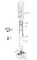
- FIG. 2Cis a side perspective view of the installation tool of FIG. 2A ;
- FIG. 2Dis a side perspective view of area “ 2 D” of FIG. 2C ;
- FIG. 2Eis a side view of the installation tool of FIG. 2A ;
- FIG. 2Fis a cross-sectional view taken along line “ 2 F- 2 F” of FIG. 2E ;
- FIG. 3Ais a side perspective view of an installation tool of the first embodiment of the present invention.
- FIG. 3Bis a side perspective view of area “ 3 B” of FIG. 3A ;
- FIG. 4is a top perspective view of a fastener
- FIG. 5Ais a bottom perspective view of an installation tool of the first embodiment of the present invention.
- FIG. 5Bis a bottom perspective view of area “ 5 B” of FIG. 5A ;
- FIGS. 6-10depict at least a portion of a sequence of operation of the first embodiment of the present invention.
- FIG. 11Ais a bottom perspective view of an installation tool of a second embodiment of the present invention.
- FIG. 11Bis a bottom perspective view of area “ 11 B” of FIG. 11A ;
- FIG. 11Cis a top view of the installation tool of FIG. 11A ;
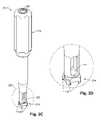
- FIG. 12Ais a side perspective view of an installation tool of the second embodiment of the present invention.
- FIG. 12Bis a bottom perspective view of area “ 12 B” of FIG. 12A ;
- FIG. 12Cis a partial cross-sectional view taken along line “ 12 C- 12 C” of FIG. 12A ;
- FIGS. 13A-Cdepict at least a portion of a sequence of operation of the second embodiment of the present invention.
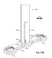
- FIG. 14depicts at least a portion of the sequence of operation of the second embodiment of the present invention.
- FIG. 1depicts a plate 100 being attached to at least one bone 102 .
- the plate 100includes at least one fastener hole 104 (three shown). Each fastener hole 104 extends from a proximal face 106 of the plate 100 and through a plate body 108 to a distal face 110 of the plate. The distal face 110 is hidden in this view, but is indicated by the dashed leader line and is located adjacent the bones 102 .
- FIGS. 2A-2F , 3 A- 3 B, and 5 A- 5 Bdepict various installation tools which collectively comprise a system for quickly and accurately attaching the plate 100 to the bone 102 while avoiding damage to adjacent tissues and structures, according to a first embodiment of the present invention.
- the tools shown and described hereinmay be used in any order, and may be made in any suitable manner and of any suitable materials.
- FIGS. 2A-2Fshow various views of a guide tool 212 , which may be a tubular guide tool as shown or have any other suitable dimensions or cross-sectional shape.
- the guide tool 212has a distal end 214 opposite a proximal handle 216 .
- the distal end 214has at least one lobe 218 adapted for contact with the plate 100 , as will be described below.
- a through bore 220extends completely through the guide tool 212 , between the proximal handle 216 and the distal end 214 .
- the through bore 220may be a central bore as shown or have any other suitable dimensions or cross-sectional shape.
- At least one view opening 222may be provided near the distal end to facilitate visualization of the plate 100 and nearby structures and/or access thereto.
- a guide orientation means 224may be located in the through bore 220 . Though the guide orientation means 224 is located within the proximal handle 216 , any other suitable location of the guide orientation means may be present.
- FIGS. 3A and 3Bshow various views of an elongated piloting member 326 having a distal end 328 adapted to prepare the bone 102 for the fastener 430 , shown in FIG. 4 .
- the fastener 430includes a plurality of helical spikes 432 (two shown in FIG. 4 ) to engage the bone 102 , with each helical spike 432 ending in a bone-penetrating tip 434 .
- the elongated piloting member 326 of FIGS. 3A and 3Btherefore is provided with two pilot tips 336 , with each pilot tip corresponding to a bone-penetrating tip 434 of a helical spike 432 of the fastener 430 .
- the pilot tips 336can be brought into contact with the bone 102 to prepare the bone for insertion of the fastener 430 .
- the fastener 430includes another style of shaft (not shown), such as the threaded post of a traditional screw or bolt
- the pilot tip 336 of the corresponding piloting member 326can readily be selected by one of ordinary skill in the art to appropriately prepare the bone 102 for insertion of the fastener having that particular style of shaft.
- the piloting member 326may include a piloting orientation means 338 , such as the stud-type structure shown in FIG. 3A .
- FIGS. 5A and 5Bshow various views of a fastener driver 540 having a distal end 542 , a proximal handle 544 , and a driver shaft 546 extending therebetween.
- a driver orientation means 548shown here as a stud-type protrusion, is associated with the driver shaft 546 .
- the fastener 430may be selectively engaged with the distal end 542 of the driver shaft 546 of the fastener driver 540 .
- one or more engagement studs 550may be located on the distal end 542 of the fastener driver 540 .
- engagement studs 550may be each adapted to frictionally engage (e.g., press-fit or wedge-fit) with a fastener drive recess feature ( 452 , in FIG. 4 ).
- a fastener drive recess feature452 , in FIG. 4 .
- the plate 100is placed in a desired contacting relationship with the bone 102 in any suitable manner.
- the guide tool 212is positioned for use, optionally with the distal locating feature (lobe 218 ) placed into a predetermined relationship with the plate 100 .
- the distal locating feature 218may contact the plate 100 when in the predetermined relationship or may be in a non-contacting arrangement; the predetermined relationship may be chosen to place the guide tool 212 in a particular orientation with respect to the plate 100 , for reasons that will shortly become apparent.
- the guide tool 212may grasp the plate 100 and/or the bone 102 , or the guide tool 212 may simply be held by the user in the desired position.
- the through bore 220may be located collinearly with a fastener hole 104 .
- the guide orientation means 224should be placed in a desired relationship to the plate 100 , for reasons which will shortly become apparent.
- FIG. 7Athe piloting member 326 has been inserted into the through bore 220 of the guide tool 212 .
- the piloting orientation means 338may be positioned for interaction with the guide orientation means 224 to help place the pilot tips 336 substantially into the eventual insertion position of the bone-penetrating tips 434 of the fastener 430 , similarly to the operation of the driver orientation means 548 , set forth below.
- forcemay be applied to the piloting member 326 (e.g., by a downward mallet tap) to indent the bone 102 with the pilot tips 336 .
- FIG. 7Bshows the plate 100 and bone 102 after the bone has been engaged by the piloting member 326 for creation of pilot holes 754 , with the guide tool 212 and piloting member having been removed from this Figure for visualization purposes.
- the fastener 430will be secured into the bone 102 as shown in the sequence of FIGS. 8A-8D .
- FIG. 8Athe fastener 430 has been engaged by the fastener driver 540 and inserted into the through bore 220 of the guide tool 212 .
- the guide tool 212is shown in partial cutaway view in FIGS. 8A-8D , to emphasize the relationship of the guide orientation means 224 and the driver orientation means 548 .
- the driver orientation means 548has not yet been mated with the guide orientation means 224 .
- the userrotates the fastener driver 540 (e.g., in the direction of clockwise arrow 854 ) until the driver orientation means 548 is longitudinally aligned with the proximal end of the guide orientation means 224 , as shown in FIG. 8A .
- the userthen moves the fastener driver 540 in the direction of the downward arrow 856 to mate the driver orientation means 548 and the guide orientation means 224 , as shown in FIG. 8B .
- the driver orientation means 548 and the guide orientation means 224are positioned on their respective fastener driver 540 and guide tool 212 to guide the fastener 430 into a desired orientation and relationship with the plate. This intentional alignment may be useful, for example, when the fastener 430 and/or the plate 100 include antibackout provisions (as discussed below), which generally need to be aligned and oriented in a particular relationship.
- the fastener driver 540is turned clockwise 854 with downward 856 force, the fastener 430 is driven through the plate 100 and into the bone 102 .
- the mating of the driver orientation means 548 and the guide orientation means 224guides at least one of a fastener travel distance, a fastener insertion orientation, and a fastener insertion pitch.
- This mating of the driver orientation means 548 and the guide orientation means 224may be helpful to the user in several ways.
- the mating of the driver orientation means 548 and the guide orientation means 224helps in inserting the fastener 430 into the bone 102 at the desired pitch. This can be an issue, especially in soft bone 102 , where, if the user applies too little or too much downward 856 force during insertion, the fastener 540 can advance too slowly or too rapidly relative to the screw pitch, and this can damage and weaken the bone and possibly decrease the holding power of the fastener 430 in the bone.
- the distal most point of engagement (when provided) of the driver orientation means 548 and the guide orientation means 224acts as a hard stop, thereby limiting the depth of travel of the fastener 430 into the bone 102 .
- the fasteners 430are able to hold the plate 100 in place on the bone 102 , but any provided antibackout feature between the fastener 430 and the plate 100 has not yet begun to engage.
- a fastener anti-backout feature 453may be a cantilevered pawl, as shown, and the plate 100 may include one or more plate anti-backout features 958 , such as the serrations shown, which engage with the fastener anti-backout feature 453 in a ratcheting manner.
- the fastener 430is not totally secured within the bone 102 , the user can confirm that the plate 100 is correctly positioned on the bone.
- the fastener and plate antibackout features 453 and 958have not yet been engaged, the plate 100 can be easily removed and repositioned, if desired.
- the usercan then use the fastener driver 540 without the guide tool 212 to finish securing the fastener(s) 430 , as shown in FIG. 10 .
- Final tightening of the fastener 430engages the fastener and plate antibackout features 453 and 958 and secures the fastener to the plate 100 .
- the ratcheting relationship of the fastener antibackout feature 453 and the plate antibackout feature 958helps to provide at least one discrete rotational position between the plate 100 and a fully secured/installed fastener 430 .
- the guide orientation means 224 and driver orientation means 548can readily design and orient the guide orientation means 224 and driver orientation means 548 accordingly. This may be desirable, for example, when a fastener hole 104 includes one or more lugs ( 160 in FIG. 1 ) which protrude radially inward into the fastener holes.
- These lugs 160when present, may be located within the gaps in between the helical spikes 432 of the fastener 430 while the fastener is being driven into the bone 102 .
- the guidance provided by the mating of the driver orientation means 548 and the guide orientation means 224helps to cause the fastener 430 to enter the fastener hole 104 with the lugs 160 positioned as desired within the gaps between the helical spikes 432 .
- FIGS. 11A-14depict various installation tools which collectively comprise a system for quickly and accurately attaching the plate 100 to the bone 102 while avoiding damage to adjacent tissues and structures, according to a second embodiment of the present invention.
- the tools shown and described hereinmay be used in any order, and may be made in any suitable manner and of any suitable materials.
- Elements of FIGS. 11A-14 which are similar to those of FIGS. 1-10are indicated by the same number with the addition of a prime. Description of structure and function of elements of the second embodiment which is substantially similar to the description above with reference to the first embodiment is omitted below, for brevity.
- FIGS. 11A-11Cshow various views of an elongated plate holder 1162 having a distal end 1164 which includes at least two spring force legs 1166 .
- the spring force legs 1166may be tapered at the distal end 1164 , as shown. No portion of the plate holder 1162 should exceed an inner diameter size of the through bore 220 ′ of the guide tool 212 ′.
- the spring force legs 1166may be adapted to resist an inward force exerted in the lateral direction 1168 , either through the use of a resistance mechanism (not shown) or simply through a stiff resilience of the material making up the plate holder 1162 .
- the plate holder 1162includes at least one side channel 1170 which is positioned and configured to help guide a guide tool 212 ′ into a desired relationship with a fastener hole 104 ′, as discussed below.
- FIGS. 12A-12Cshow various views of a guide tool 212 ′ for use with the second embodiment of the present invention.
- the lobes 218 ′ of the guide tool 212 ′protrude from the through bore 220 ′ and are constructed more compactly with the guide tool 212 ′ of the second embodiment than are the lobes 218 of the guide tool 212 of the first embodiment, for reasons which will become apparent shortly.
- FIGS. 13A-14depict selected steps in the operation of the second embodiment of the present invention.
- the distal end 1164 of the plate holder 1162is inserted in the fastener hole 104 ′ for engagement thereof.
- the total diameter of the distal end 1164 of the plate holder 1162may be slightly larger than the inner diameter of the fastener hole 104 ′, thus introducing frictional engagement via a force exerted upon the fastener hole by the plate holder in the lateral direction 1168 .
- a spring expansion mechanism(not shown) could be located within the distal end 1164 of the plate holder. Because of the engagement, however provided, the plate holder 1162 grasps the plate 100 ′ and may be manipulated to move the plate into a desired placement with respect to the bone 102 ′.
- an optional shoulder 1372may be seen.
- the shoulder 1372when present, interacts with the proximal face 106 ′ of the plate to prevent the inserted distal end 1164 of the plate holder 1162 from extending or protruding beyond the distal face 110 ′ of the plate 100 ′, which can be seen in FIG. 13C .
- the distal end 1164 of the plate holder 1162can accordingly be flush with, or slightly retracted proximally into, the plate 100 ′ and thus not exert a downwardly 856 ′ directed force upon the bone 102 ′.
- a plurality of retaining pins 1374may be seen to protrude from the distal face 110 ′ of the plate 100 ′.
- the retaining pins 1374may be pressed into the bone 102 ′ to temporarily retain the plate 100 ′ in a desired placement with respect to the bone 102 ′.
- One example method of pressing the retaining pins 1374 into the bone 102 ′is to apply force to a proximal end (not shown in this view) of the plate holder 1162 to engage the bone with the retaining pins.
- FIG. 13Cshows the lugs 160 ′ of the plate 100 ′ as being located in the unnumbered gap laterally between the spring force legs 1166 when the spring force legs are inserted into the fastener hole 104 ′.
- the lugs 160 ′may substantially prevent the spring force legs 1166 from rotary movement within the fastener hole 104 ′.
- FIG. 13Cthe relationship of the lobes 218 ′ of the guide tool 212 ′ to the side channels 1170 of the plate holder 1162 is shown.
- the side channels 1170accept and guide the lobes 218 ′ as the guide tool 212 ′ is slid downward 856 ′ around the plate holder 1162 .
- Each side channel 1170may extend at least semi-contiguously with a guide pocket 1376 , where each guide pocket 1376 extends from the fastener hole 104 ′ of the plate 100 ′.
- the guide pockets 1376are thus operative to orient the guide tool 212 ′ into a particular rotary relationship with the fastener hole 104 ′.
- one of ordinary skill in the artcould readily design one or more of the lobe(s) 218 ′, side channel(s) 1170 , guide pocket(s) 1376 , spring force leg(s) 1166 , lug(s) 160 ′, or any other distal locating feature(s) or other structures of the present invention to place the guide tool 212 ′ in a desired orientation with respect to the fastener hole 104 ′, and as a result, the guide orientation means 224 ′ (in a known location on the guide tool 212 ′) can readily be placed to mate with the driver orientation means 548 ′ to guide the fastener 430 ′ into a substantially precise final installation position.
- the lobe 218 ′may include at least a portion protruding into the through bore 220 ′ of the guide tool 212 ′. Also as shown in FIG. 14 , this internally-oriented lobe 218 ′ may be positioned to interact with a ratchet tooth 1478 of the plate antibackout feature 958 ′, in order to help restrict rotation of the guide tool 212 ′ with respect to the fastener hole 104 ′. It should be noted that, regardless of the structures located permanently or temporarily within the through bore 220 ′, the through bore should generally allow a free clearance inside diameter equal to or greater than the effective inside diameter (usable space) within the fastener hole 104 ′.
- any items which need to enter and/or pass through the fastener hole 104 ′can fit through the through bore 220 ′.
- An example of an exception to this recommendationmight be one or more protruding lugs (not shown) within the through bore 220 ′ which are oriented and placed to remain within the gap between the helical spikes 432 ′ of the fastener 430 ′ as the fastener is screwed into engagement with the bone 102 —such lugs may function to reduce the free clearance inside diameter, yet be present for the purpose of helping to orient and/or guide the helical spikes.
- FIG. 14shows the guide tool 212 ′ after the plate holder 1162 has been withdrawn in a proximal direction from the through bore 220 ′.
- the guide tool 212 ′is now ready to accept and guide the fastener driver 540 ′ and fastener 430 ′ to secure the plate 100 ′ to the bone 102 ′ with the fastener in a manner similar to that set forth above with reference to the first embodiment of the present invention.
- the guide orientation means 224 and driver orientation means 548 of any embodiment of the present inventionmay have any suitable form, placement, size, orientation, interaction, or any other physical characteristics.
- either one of the driver orientation means 548 and the guide orientation means 224may protrude from its respective fastener driver 548 and guide tool 212 , while the other of the driver orientation means and the guide orientation means may be recessed into its respective fastener driver and guide tool.
- At least one of the driver orientation means 548 and the guide orientation means 224may include an internal thread having the same pitch as the fastener 430 , with the other of the driver orientation means and the guide orientation means having a corresponding external thread.
- Either of the driver orientation means 548 and the guide orientation means 224may be located at any suitable interior or exterior location on its respective fastener driver 540 and guide tool 212 . Similar options and configurations may be readily provided by one of ordinary skill in the art for the lugs 160 ′ and spring force legs 1166 , and the side channels 1170 and lobes 218 ′.
- the guide orientation means 224 and driver orientation means 548 , the fastener driver 540 and fastener 430 , or any other structures of the systemmay be placed into a magnetic relationship with each other.
- the clockwise description of fastener driver 540 operationis based upon a common mechanical screw-engagement standard; a ratcheting feature, counter-clockwise engagement, or even longitudinal impact-driving motion, as well as any other desired driving motion, could be additionally or alternatively provided.
- the plate holder 1162may grasp the plate differently than shown; for example, an adhesive structure, frangible linkage, turn-lock mechanism, or any other suitable grasping means may be controllable by the user to grasp and release the plate 100 ′.
- a structure described herein as “contacting” another structurecould also or instead engage that other structure in any suitable manner.
- Any structures of the present inventioncan permanently or temporarily frictionally engage any other structure(s) as desired, using any suitably designed static or dynamic components to do so.
- a device or method incorporating any of these featuresshould be understood to fall under the scope of the present invention as determined based upon the claims below and any equivalents thereof.
Landscapes
- Health & Medical Sciences (AREA)
- Orthopedic Medicine & Surgery (AREA)
- Surgery (AREA)
- Life Sciences & Earth Sciences (AREA)
- Biomedical Technology (AREA)
- Public Health (AREA)
- Veterinary Medicine (AREA)
- Engineering & Computer Science (AREA)
- Nuclear Medicine, Radiotherapy & Molecular Imaging (AREA)
- Heart & Thoracic Surgery (AREA)
- Medical Informatics (AREA)
- Molecular Biology (AREA)
- Animal Behavior & Ethology (AREA)
- General Health & Medical Sciences (AREA)
- Dentistry (AREA)
- Oral & Maxillofacial Surgery (AREA)
- Neurology (AREA)
- Surgical Instruments (AREA)
Abstract
Description
Claims (1)
Priority Applications (1)
| Application Number | Priority Date | Filing Date | Title |
|---|---|---|---|
| US12/603,631US8425573B2 (en) | 2008-10-24 | 2009-10-22 | Method and system for attaching a plate to a bone |
Applications Claiming Priority (2)
| Application Number | Priority Date | Filing Date | Title |
|---|---|---|---|
| US10828008P | 2008-10-24 | 2008-10-24 | |
| US12/603,631US8425573B2 (en) | 2008-10-24 | 2009-10-22 | Method and system for attaching a plate to a bone |
Publications (2)
| Publication Number | Publication Date |
|---|---|
| US20100106196A1 US20100106196A1 (en) | 2010-04-29 |
| US8425573B2true US8425573B2 (en) | 2013-04-23 |
Family
ID=42118211
Family Applications (1)
| Application Number | Title | Priority Date | Filing Date |
|---|---|---|---|
| US12/603,631Expired - Fee RelatedUS8425573B2 (en) | 2008-10-24 | 2009-10-22 | Method and system for attaching a plate to a bone |
Country Status (1)
| Country | Link |
|---|---|
| US (1) | US8425573B2 (en) |
Cited By (7)
| Publication number | Priority date | Publication date | Assignee | Title |
|---|---|---|---|---|
| US20120071934A1 (en)* | 2010-08-26 | 2012-03-22 | Mark Leonard Brandon | Locking plates having guided locking screws and methods therefor |
| WO2015130609A3 (en)* | 2014-02-27 | 2015-12-10 | Biomedical Enterprises, Inc. | Method and apparatus for use of a compressing plate |
| US9911019B2 (en) | 2014-11-25 | 2018-03-06 | DePuy Synthes Products, Inc. | Medical device identification system |
| US11123117B1 (en) | 2011-11-01 | 2021-09-21 | Nuvasive, Inc. | Surgical fixation system and related methods |
| US20220183704A1 (en)* | 2019-03-29 | 2022-06-16 | Medacta International Sa | A surgical device |
| US11517451B2 (en) | 2015-12-30 | 2022-12-06 | Nuvasive, Inc. | Interfixated vertebral body replacement and insertion methods |
| US20240099748A1 (en)* | 2020-12-17 | 2024-03-28 | Dgt Medical Limited | A bone fixation device and system and method for using the device |
Families Citing this family (23)
| Publication number | Priority date | Publication date | Assignee | Title |
|---|---|---|---|---|
| US8118846B2 (en)* | 2005-01-28 | 2012-02-21 | Orthohelix Surgical Designs, Inc. | Orthopedic plates for use in clavicle repair and methods for their use |
| US8257407B2 (en)* | 2008-04-23 | 2012-09-04 | Aryan Henry E | Bone plate system and method |
| US8337533B2 (en)* | 2008-06-20 | 2012-12-25 | Osteomed Llc | Locking plate benders |
| US20110082506A1 (en)* | 2009-10-02 | 2011-04-07 | Spinefrontier, Inc | Cervical plate assembly |
| WO2012050572A1 (en) | 2010-10-13 | 2012-04-19 | Stryker Leibinger Gmbh & Co., Kg. | Bone plate aiming block |
| US8523862B2 (en)* | 2011-04-04 | 2013-09-03 | Stryker Leibinger Gmbh & Co. Kg | Bone plate aiming block |
| US8998988B2 (en)* | 2010-12-29 | 2015-04-07 | Spinal Usa, Inc. | Buttress plate system |
| US8840667B1 (en) | 2011-06-16 | 2014-09-23 | Luis M Tumialán | Spinal plate system and related methods |
| CA2927433C (en)* | 2012-10-15 | 2020-03-10 | Dynamic Spine, Llc | Orthopaedic device with orthopaedic plate and rotatable tissue protector |
| US10076369B2 (en)* | 2013-01-16 | 2018-09-18 | Spinefrontier, Inc | Bone fastener for a spinal fixation assembly |
| AU2014365821B2 (en) | 2013-12-20 | 2019-10-03 | Crossroads Extremity Systems, Llc | Polyaxial locking hole |
| US11202626B2 (en) | 2014-07-10 | 2021-12-21 | Crossroads Extremity Systems, Llc | Bone implant with means for multi directional force and means of insertion |
| JP2017529886A (en) | 2014-07-10 | 2017-10-12 | クロスローズ エクストリミティ システムズ リミテッド ライアビリティ カンパニー | Bone implant and means of insertion |
| WO2016025162A1 (en)* | 2014-08-12 | 2016-02-18 | Orthodiscovery Group Llc | Bone implant with means for multi directional force |
| WO2017011589A1 (en) | 2015-07-13 | 2017-01-19 | Crossroads Extremity Systems, Llc | Bone plates with dynamic elements |
| EP3562414A2 (en)* | 2016-12-27 | 2019-11-06 | Depuy Synthes Products, Inc. | Bone plate fastening system |
| US11864753B2 (en) | 2017-02-06 | 2024-01-09 | Crossroads Extremity Systems, Llc | Implant inserter |
| EP3579762B1 (en) | 2017-02-07 | 2024-06-26 | Crossroads Extremity Systems, LLC | Counter-torque implant |
| WO2021062102A1 (en)* | 2019-09-27 | 2021-04-01 | Trilliant Surgical Llc | Bone fixation system |
| US12059183B2 (en) | 2020-07-31 | 2024-08-13 | Crossroads Extremity Systems, Llc | Bone plates with dynamic elements and screws |
| US12011199B2 (en)* | 2020-10-15 | 2024-06-18 | DePuy Synthes Products, Inc. | Bone plate, bone plate system, and method of using the same |
| USD961081S1 (en) | 2020-11-18 | 2022-08-16 | Crossroads Extremity Systems, Llc | Orthopedic implant |
| US11963704B2 (en)* | 2021-09-16 | 2024-04-23 | Warsaw Orthopedic, Inc. | Surgical instrument and method |
Citations (49)
| Publication number | Priority date | Publication date | Assignee | Title |
|---|---|---|---|---|
| US2248054A (en)* | 1939-06-07 | 1941-07-08 | Becker Joseph | Screw driver |
| US2318152A (en)* | 1941-08-16 | 1943-05-04 | Gelardin Albert | Cosmetic holder |
| US2494229A (en)* | 1946-07-08 | 1950-01-10 | John G Collison | Bone surgery |
| US2623231A (en)* | 1949-02-02 | 1952-12-30 | Gutenstein Joseph | Nail polish applicator |
| US4755092A (en)* | 1984-09-14 | 1988-07-05 | Galram Technology Industries Limited | Quick-action fastener |
| US5364399A (en) | 1993-02-05 | 1994-11-15 | Danek Medical, Inc. | Anterior cervical plating system |
| US5423826A (en) | 1993-02-05 | 1995-06-13 | Danek Medical, Inc. | Anterior cervical plate holder/drill guide and method of use |
| US5429641A (en) | 1993-03-28 | 1995-07-04 | Gotfried; Yechiel | Surgical device for connection of fractured bones |
| US5489307A (en) | 1993-02-10 | 1996-02-06 | Spine-Tech, Inc. | Spinal stabilization surgical method |
| US5569264A (en)* | 1992-01-24 | 1996-10-29 | Biocon Oy | Surgical installation instrument |
| US5643274A (en)* | 1993-06-21 | 1997-07-01 | United States Surgical Corporation | Orthopedic fastener applicator kit |
| US5680954A (en)* | 1994-08-10 | 1997-10-28 | Cummins Engine Company, Inc. | Oil fill cap |
| US5722105A (en)* | 1995-12-28 | 1998-03-03 | Thomasson; Stig Ola | Floor mop and wringing mechanism therefor |
| US5755721A (en) | 1996-03-13 | 1998-05-26 | Synthes | Plate holding drill guide and trocar and method of holding a plate |
| US5921456A (en) | 1996-07-03 | 1999-07-13 | Axel Kirsch | Setting tool for nails |
| US6139549A (en)* | 1996-04-09 | 2000-10-31 | Waldemar Link (Gmbh & Co.) | Spinal fixing device |
| US6251112B1 (en) | 2000-04-18 | 2001-06-26 | Roger P. Jackson | Thin profile closure cap for open ended medical implant |
| US6299616B1 (en)* | 1998-11-07 | 2001-10-09 | Aesculap Ag & Co. Kg | Endoscopic insertion apparatus |
| US6379364B1 (en) | 2000-04-28 | 2002-04-30 | Synthes (Usa) | Dual drill guide for a locking bone plate |
| US20020082606A1 (en)* | 2000-12-21 | 2002-06-27 | Loubert Suddaby | Drill guide |
| US6436100B1 (en) | 1998-08-07 | 2002-08-20 | J. Lee Berger | Cannulated internally threaded bone screw and reduction driver device |
| US20020151899A1 (en)* | 2001-04-17 | 2002-10-17 | Bailey Kirk J. | Anterior cervical plating system |
| US20020183138A1 (en)* | 1999-12-04 | 2002-12-05 | Malcolm George Edward | Combination golf apparatus |
| US20030023246A1 (en)* | 2001-07-26 | 2003-01-30 | Yechiel Gotfried | Surgical device and method for connection of fractured bones |
| US6565571B1 (en) | 1998-10-19 | 2003-05-20 | Scient'x | Anterior osteosynthesis plate for lumbar vertebrae or sacral lumbar vertebra and instrument for positioning same |
| US20030153916A1 (en) | 1993-06-10 | 2003-08-14 | Sofamor Danek Holdings, Inc. | Method of inserting spinal implants with the use of imaging |
| US6702817B2 (en) | 2001-01-19 | 2004-03-09 | Aesculap Ag & Co. Kg | Locking mechanism for a bone screw |
| US20040092947A1 (en)* | 2002-09-30 | 2004-05-13 | Foley Kevin T. | Devices and methods for securing a bone plate to a bony segment |
| US20040093971A1 (en)* | 2001-01-23 | 2004-05-20 | Shigeki Fujibayashi | Feed screw driver and information recorder/reproducer |
| USRE38684E1 (en) | 1997-07-01 | 2005-01-04 | Synthes Ag Chur | Freely separable surgical drill guide and plate |
| US20050015093A1 (en)* | 2003-07-16 | 2005-01-20 | Suh Sean S. | Plating system with compression drill guide |
| US20050038444A1 (en)* | 2003-08-13 | 2005-02-17 | Binder Lawrence J. | Quick-release drill-guide assembly for bone-plate |
| US20050149053A1 (en) | 2003-12-17 | 2005-07-07 | Varieur Michael S. | Instruments and methods for bone anchor engagement and spinal rod reduction |
| US6923814B1 (en)* | 2001-10-30 | 2005-08-02 | Nuvasive, Inc. | System and methods for cervical spinal fusion |
| US6932822B2 (en) | 2000-03-28 | 2005-08-23 | Showa Ika Kohgyo Co., Ltd. | Spinal implant, driver tool and nut guide |
| US20050228398A1 (en)* | 2004-04-12 | 2005-10-13 | Rathbun David S | Free hand drill guide |
| US20050251137A1 (en)* | 2003-12-12 | 2005-11-10 | Kinetikos Medical Inc. | Apparatuses, systems and methods for bone fixation |
| US20060155298A1 (en)* | 2003-03-07 | 2006-07-13 | Theken Surgical, Llc | Instrument guide and implant holder |
| US7137985B2 (en) | 2003-09-24 | 2006-11-21 | N Spine, Inc. | Marking and guidance method and system for flexible fixation of a spine |
| US20060293693A1 (en) | 2005-06-08 | 2006-12-28 | Innovative Spine, Llc | Sleeve assembly for spinal stabilization system and methods of use |
| US7166111B2 (en)* | 2004-12-08 | 2007-01-23 | Depuy Spine, Inc. | Spinal plate and drill guide |
| US7258694B1 (en)* | 2002-06-17 | 2007-08-21 | Origin Medsystems, Inc. | Medical punch and surgical procedure |
| US20070213726A1 (en)* | 2006-02-08 | 2007-09-13 | Synthes, Inc. | Transbuccal plate holding cannula |
| US20070260261A1 (en) | 2005-06-02 | 2007-11-08 | Depuy Spine, Inc. | Instruments and methods for manipulating a spinal fixation element |
| US20070265499A1 (en)* | 2006-05-09 | 2007-11-15 | Boston Scientific Scimed, Inc. | Medical device positioning system |
| US7297166B2 (en) | 2003-06-25 | 2007-11-20 | Depuy Products, Inc. | Assembly tool for modular implants and associated method |
| US20080097444A1 (en)* | 2006-07-21 | 2008-04-24 | Merlot Orthopedix | Apparatus and method for body tissue fixation |
| US20090036933A1 (en)* | 2007-07-31 | 2009-02-05 | Stryker Spine | System and method for vertebral body plating |
| US7666189B2 (en)* | 2004-09-29 | 2010-02-23 | Synthes Usa, Llc | Less invasive surgical system and methods |
Family Cites Families (2)
| Publication number | Priority date | Publication date | Assignee | Title |
|---|---|---|---|---|
| US38684A (en)* | 1863-05-26 | Improvement in cylinder-molds for making paper | ||
| JP2887752B2 (en)* | 1997-08-15 | 1999-04-26 | 株式会社東京機械製作所 | Paper feeder in paper threader |
- 2009
- 2009-10-22USUS12/603,631patent/US8425573B2/ennot_activeExpired - Fee Related
Patent Citations (51)
| Publication number | Priority date | Publication date | Assignee | Title |
|---|---|---|---|---|
| US2248054A (en)* | 1939-06-07 | 1941-07-08 | Becker Joseph | Screw driver |
| US2318152A (en)* | 1941-08-16 | 1943-05-04 | Gelardin Albert | Cosmetic holder |
| US2494229A (en)* | 1946-07-08 | 1950-01-10 | John G Collison | Bone surgery |
| US2623231A (en)* | 1949-02-02 | 1952-12-30 | Gutenstein Joseph | Nail polish applicator |
| US4755092A (en)* | 1984-09-14 | 1988-07-05 | Galram Technology Industries Limited | Quick-action fastener |
| US5569264A (en)* | 1992-01-24 | 1996-10-29 | Biocon Oy | Surgical installation instrument |
| US5364399A (en) | 1993-02-05 | 1994-11-15 | Danek Medical, Inc. | Anterior cervical plating system |
| US5423826A (en) | 1993-02-05 | 1995-06-13 | Danek Medical, Inc. | Anterior cervical plate holder/drill guide and method of use |
| US5489307A (en) | 1993-02-10 | 1996-02-06 | Spine-Tech, Inc. | Spinal stabilization surgical method |
| US5429641A (en) | 1993-03-28 | 1995-07-04 | Gotfried; Yechiel | Surgical device for connection of fractured bones |
| US6875213B2 (en) | 1993-06-10 | 2005-04-05 | Sdgi Holdings, Inc. | Method of inserting spinal implants with the use of imaging |
| US20030153916A1 (en) | 1993-06-10 | 2003-08-14 | Sofamor Danek Holdings, Inc. | Method of inserting spinal implants with the use of imaging |
| US5643274A (en)* | 1993-06-21 | 1997-07-01 | United States Surgical Corporation | Orthopedic fastener applicator kit |
| US5680954A (en)* | 1994-08-10 | 1997-10-28 | Cummins Engine Company, Inc. | Oil fill cap |
| US5722105A (en)* | 1995-12-28 | 1998-03-03 | Thomasson; Stig Ola | Floor mop and wringing mechanism therefor |
| US5755721A (en) | 1996-03-13 | 1998-05-26 | Synthes | Plate holding drill guide and trocar and method of holding a plate |
| US6139549A (en)* | 1996-04-09 | 2000-10-31 | Waldemar Link (Gmbh & Co.) | Spinal fixing device |
| US5921456A (en) | 1996-07-03 | 1999-07-13 | Axel Kirsch | Setting tool for nails |
| USRE38684E1 (en) | 1997-07-01 | 2005-01-04 | Synthes Ag Chur | Freely separable surgical drill guide and plate |
| US6436100B1 (en) | 1998-08-07 | 2002-08-20 | J. Lee Berger | Cannulated internally threaded bone screw and reduction driver device |
| US6565571B1 (en) | 1998-10-19 | 2003-05-20 | Scient'x | Anterior osteosynthesis plate for lumbar vertebrae or sacral lumbar vertebra and instrument for positioning same |
| US6299616B1 (en)* | 1998-11-07 | 2001-10-09 | Aesculap Ag & Co. Kg | Endoscopic insertion apparatus |
| US20020183138A1 (en)* | 1999-12-04 | 2002-12-05 | Malcolm George Edward | Combination golf apparatus |
| US6932822B2 (en) | 2000-03-28 | 2005-08-23 | Showa Ika Kohgyo Co., Ltd. | Spinal implant, driver tool and nut guide |
| US6251112B1 (en) | 2000-04-18 | 2001-06-26 | Roger P. Jackson | Thin profile closure cap for open ended medical implant |
| US6379364B1 (en) | 2000-04-28 | 2002-04-30 | Synthes (Usa) | Dual drill guide for a locking bone plate |
| US20020082606A1 (en)* | 2000-12-21 | 2002-06-27 | Loubert Suddaby | Drill guide |
| US6702817B2 (en) | 2001-01-19 | 2004-03-09 | Aesculap Ag & Co. Kg | Locking mechanism for a bone screw |
| US20040093971A1 (en)* | 2001-01-23 | 2004-05-20 | Shigeki Fujibayashi | Feed screw driver and information recorder/reproducer |
| US20020151899A1 (en)* | 2001-04-17 | 2002-10-17 | Bailey Kirk J. | Anterior cervical plating system |
| US20030023246A1 (en)* | 2001-07-26 | 2003-01-30 | Yechiel Gotfried | Surgical device and method for connection of fractured bones |
| US6923814B1 (en)* | 2001-10-30 | 2005-08-02 | Nuvasive, Inc. | System and methods for cervical spinal fusion |
| US7258694B1 (en)* | 2002-06-17 | 2007-08-21 | Origin Medsystems, Inc. | Medical punch and surgical procedure |
| US20040092947A1 (en)* | 2002-09-30 | 2004-05-13 | Foley Kevin T. | Devices and methods for securing a bone plate to a bony segment |
| US7278997B1 (en) | 2003-03-07 | 2007-10-09 | Theken Spine, Llc | Instrument guide and implant holder |
| US20060155298A1 (en)* | 2003-03-07 | 2006-07-13 | Theken Surgical, Llc | Instrument guide and implant holder |
| US7297166B2 (en) | 2003-06-25 | 2007-11-20 | Depuy Products, Inc. | Assembly tool for modular implants and associated method |
| US20050015093A1 (en)* | 2003-07-16 | 2005-01-20 | Suh Sean S. | Plating system with compression drill guide |
| US20050038444A1 (en)* | 2003-08-13 | 2005-02-17 | Binder Lawrence J. | Quick-release drill-guide assembly for bone-plate |
| US7137985B2 (en) | 2003-09-24 | 2006-11-21 | N Spine, Inc. | Marking and guidance method and system for flexible fixation of a spine |
| US20050251137A1 (en)* | 2003-12-12 | 2005-11-10 | Kinetikos Medical Inc. | Apparatuses, systems and methods for bone fixation |
| US20050149053A1 (en) | 2003-12-17 | 2005-07-07 | Varieur Michael S. | Instruments and methods for bone anchor engagement and spinal rod reduction |
| US20050228398A1 (en)* | 2004-04-12 | 2005-10-13 | Rathbun David S | Free hand drill guide |
| US7666189B2 (en)* | 2004-09-29 | 2010-02-23 | Synthes Usa, Llc | Less invasive surgical system and methods |
| US7166111B2 (en)* | 2004-12-08 | 2007-01-23 | Depuy Spine, Inc. | Spinal plate and drill guide |
| US20070260261A1 (en) | 2005-06-02 | 2007-11-08 | Depuy Spine, Inc. | Instruments and methods for manipulating a spinal fixation element |
| US20060293693A1 (en) | 2005-06-08 | 2006-12-28 | Innovative Spine, Llc | Sleeve assembly for spinal stabilization system and methods of use |
| US20070213726A1 (en)* | 2006-02-08 | 2007-09-13 | Synthes, Inc. | Transbuccal plate holding cannula |
| US20070265499A1 (en)* | 2006-05-09 | 2007-11-15 | Boston Scientific Scimed, Inc. | Medical device positioning system |
| US20080097444A1 (en)* | 2006-07-21 | 2008-04-24 | Merlot Orthopedix | Apparatus and method for body tissue fixation |
| US20090036933A1 (en)* | 2007-07-31 | 2009-02-05 | Stryker Spine | System and method for vertebral body plating |
Cited By (11)
| Publication number | Priority date | Publication date | Assignee | Title |
|---|---|---|---|---|
| US20120071934A1 (en)* | 2010-08-26 | 2012-03-22 | Mark Leonard Brandon | Locking plates having guided locking screws and methods therefor |
| US8894694B2 (en)* | 2010-08-26 | 2014-11-25 | Mark Leonard Brandon | Locking plates having guided locking screws and methods therefor |
| US11123117B1 (en) | 2011-11-01 | 2021-09-21 | Nuvasive, Inc. | Surgical fixation system and related methods |
| WO2015130609A3 (en)* | 2014-02-27 | 2015-12-10 | Biomedical Enterprises, Inc. | Method and apparatus for use of a compressing plate |
| CN106132325A (en)* | 2014-02-27 | 2016-11-16 | 生物医药企业公司 | The method and apparatus using compression plate |
| CN106132325B (en)* | 2014-02-27 | 2019-08-13 | 生物医药企业公司 | Use the method and apparatus of compression plate |
| US9911019B2 (en) | 2014-11-25 | 2018-03-06 | DePuy Synthes Products, Inc. | Medical device identification system |
| US11517451B2 (en) | 2015-12-30 | 2022-12-06 | Nuvasive, Inc. | Interfixated vertebral body replacement and insertion methods |
| US20220183704A1 (en)* | 2019-03-29 | 2022-06-16 | Medacta International Sa | A surgical device |
| US12285179B2 (en)* | 2019-03-29 | 2025-04-29 | Medacta International Sa | Surgical device |
| US20240099748A1 (en)* | 2020-12-17 | 2024-03-28 | Dgt Medical Limited | A bone fixation device and system and method for using the device |
Also Published As
| Publication number | Publication date |
|---|---|
| US20100106196A1 (en) | 2010-04-29 |
Similar Documents
| Publication | Publication Date | Title |
|---|---|---|
| US8425573B2 (en) | Method and system for attaching a plate to a bone | |
| US11813172B2 (en) | Facet screw and delivery device | |
| US7883510B2 (en) | Vertebral staples and insertion tools | |
| US7141074B2 (en) | Variable depth drill with self-centering sleeve | |
| RU2601982C2 (en) | Augmentable trochanteric femoral nail | |
| US10376379B2 (en) | Bone stabilization implants, instruments, and methods | |
| US20060149245A1 (en) | Bone fixation system | |
| US20090326545A1 (en) | Systems and methods for inserting a bone anchor without a pilot hole | |
| KR20120082396A (en) | Bone plate screw-blocking systems and methods | |
| US20090287257A1 (en) | Cervical plate | |
| KR20120028878A (en) | Arcuate spinal fixation member | |
| US9358050B2 (en) | Orthopedic anchor assembly | |
| KR20090015073A (en) | Methods and instruments for spinal fixation | |
| KR20130037669A (en) | Systems and methods for minimally invasive surgic al procedures | |
| US12295850B2 (en) | Systems, methods, and devices for lateral and posterior sacroiliac joint fusion | |
| US12201335B2 (en) | All in one plate holder and spring loaded awl | |
| US11490934B1 (en) | Spinal implant system and method | |
| JP7651318B2 (en) | Anchor Delivery System | |
| US10076370B2 (en) | Clip for dynamic spinal plate | |
| US20250268589A1 (en) | Neuromonitoring dilators, probes, and cannulated blades for modular tissue retractor | |
| US20240252215A1 (en) | Targeting and insertion instrument for orthopedic implants | |
| JP4326332B2 (en) | Method and instrument for interbody fusion |
Legal Events
| Date | Code | Title | Description |
|---|---|---|---|
| AS | Assignment | Owner name:MERLOT ORTHOPEDIX,OHIO Free format text:ASSIGNMENT OF ASSIGNORS INTEREST;ASSIGNORS:ERICKSON, PAUL L.;KEVERLINE, STEPHEN EDWARD;REEL/FRAME:023628/0758 Effective date:20091110 Owner name:THE CLEVELAND CLINIC FOUNDATION,OHIO Free format text:ASSIGNMENT OF ASSIGNORS INTEREST;ASSIGNOR:LIEBERMAN, ISADOR H.;REEL/FRAME:023629/0119 Effective date:20091101 Owner name:THE CLEVELAND CLINIC FOUNDATION, OHIO Free format text:ASSIGNMENT OF ASSIGNORS INTEREST;ASSIGNOR:LIEBERMAN, ISADOR H.;REEL/FRAME:023629/0119 Effective date:20091101 Owner name:MERLOT ORTHOPEDIX, OHIO Free format text:ASSIGNMENT OF ASSIGNORS INTEREST;ASSIGNORS:ERICKSON, PAUL L.;KEVERLINE, STEPHEN EDWARD;REEL/FRAME:023628/0758 Effective date:20091110 | |
| AS | Assignment | Owner name:MERLOT ORTHOPEDIX INC.,OHIO Free format text:CORRECTIVE ASSIGNMENT TO CORRECT THE RECEIVING PARTY DATA NAME PREVIOUSLY RECORDED ON REEL 023628 FRAME 0758. ASSIGNOR(S) HEREBY CONFIRMS THE CORRECTION OF THE NAME OF THE RECEIVING PARTY FROM MERLOT ORTHOPEDIX TO MERLOT ORTHOPEDIX INC.;ASSIGNORS:ERICKSON, PAUL L.;KEVERLINE, STEPHEN EDWARD;REEL/FRAME:023632/0034 Effective date:20091110 Owner name:MERLOT ORTHOPEDIX INC., OHIO Free format text:CORRECTIVE ASSIGNMENT TO CORRECT THE RECEIVING PARTY DATA NAME PREVIOUSLY RECORDED ON REEL 023628 FRAME 0758. ASSIGNOR(S) HEREBY CONFIRMS THE CORRECTION OF THE NAME OF THE RECEIVING PARTY FROM MERLOT ORTHOPEDIX TO MERLOT ORTHOPEDIX INC.;ASSIGNORS:ERICKSON, PAUL L.;KEVERLINE, STEPHEN EDWARD;REEL/FRAME:023632/0034 Effective date:20091110 | |
| STCF | Information on status: patent grant | Free format text:PATENTED CASE | |
| FPAY | Fee payment | Year of fee payment:4 | |
| FEPP | Fee payment procedure | Free format text:MAINTENANCE FEE REMINDER MAILED (ORIGINAL EVENT CODE: REM.); ENTITY STATUS OF PATENT OWNER: SMALL ENTITY | |
| LAPS | Lapse for failure to pay maintenance fees | Free format text:PATENT EXPIRED FOR FAILURE TO PAY MAINTENANCE FEES (ORIGINAL EVENT CODE: EXP.); ENTITY STATUS OF PATENT OWNER: SMALL ENTITY | |
| STCH | Information on status: patent discontinuation | Free format text:PATENT EXPIRED DUE TO NONPAYMENT OF MAINTENANCE FEES UNDER 37 CFR 1.362 | |
| FP | Lapsed due to failure to pay maintenance fee | Effective date:20210423 |