US8425493B2 - Implantable medication delivery device - Google Patents
Implantable medication delivery deviceDownload PDFInfo
- Publication number
- US8425493B2 US8425493B2US10/515,152US51515205AUS8425493B2US 8425493 B2US8425493 B2US 8425493B2US 51515205 AUS51515205 AUS 51515205AUS 8425493 B2US8425493 B2US 8425493B2
- Authority
- US
- United States
- Prior art keywords
- reservoir
- pressure
- medication
- pump chamber
- port
- Prior art date
- Legal status (The legal status is an assumption and is not a legal conclusion. Google has not performed a legal analysis and makes no representation as to the accuracy of the status listed.)
- Active, expires
Links
Images


Classifications
- A—HUMAN NECESSITIES
- A61—MEDICAL OR VETERINARY SCIENCE; HYGIENE
- A61M—DEVICES FOR INTRODUCING MEDIA INTO, OR ONTO, THE BODY; DEVICES FOR TRANSDUCING BODY MEDIA OR FOR TAKING MEDIA FROM THE BODY; DEVICES FOR PRODUCING OR ENDING SLEEP OR STUPOR
- A61M5/00—Devices for bringing media into the body in a subcutaneous, intra-vascular or intramuscular way; Accessories therefor, e.g. filling or cleaning devices, arm-rests
- A61M5/14—Infusion devices, e.g. infusing by gravity; Blood infusion; Accessories therefor
- A61M5/142—Pressure infusion, e.g. using pumps
- A61M5/14212—Pumping with an aspiration and an expulsion action
- A61M5/14224—Diaphragm type
- A—HUMAN NECESSITIES
- A61—MEDICAL OR VETERINARY SCIENCE; HYGIENE
- A61M—DEVICES FOR INTRODUCING MEDIA INTO, OR ONTO, THE BODY; DEVICES FOR TRANSDUCING BODY MEDIA OR FOR TAKING MEDIA FROM THE BODY; DEVICES FOR PRODUCING OR ENDING SLEEP OR STUPOR
- A61M5/00—Devices for bringing media into the body in a subcutaneous, intra-vascular or intramuscular way; Accessories therefor, e.g. filling or cleaning devices, arm-rests
- A61M5/14—Infusion devices, e.g. infusing by gravity; Blood infusion; Accessories therefor
- A61M5/142—Pressure infusion, e.g. using pumps
- A61M5/14244—Pressure infusion, e.g. using pumps adapted to be carried by the patient, e.g. portable on the body
- A61M5/14276—Pressure infusion, e.g. using pumps adapted to be carried by the patient, e.g. portable on the body specially adapted for implantation
- A—HUMAN NECESSITIES
- A61—MEDICAL OR VETERINARY SCIENCE; HYGIENE
- A61M—DEVICES FOR INTRODUCING MEDIA INTO, OR ONTO, THE BODY; DEVICES FOR TRANSDUCING BODY MEDIA OR FOR TAKING MEDIA FROM THE BODY; DEVICES FOR PRODUCING OR ENDING SLEEP OR STUPOR
- A61M5/00—Devices for bringing media into the body in a subcutaneous, intra-vascular or intramuscular way; Accessories therefor, e.g. filling or cleaning devices, arm-rests
- A61M5/14—Infusion devices, e.g. infusing by gravity; Blood infusion; Accessories therefor
- A61M5/142—Pressure infusion, e.g. using pumps
- A61M5/14244—Pressure infusion, e.g. using pumps adapted to be carried by the patient, e.g. portable on the body
- A61M2005/14264—Pressure infusion, e.g. using pumps adapted to be carried by the patient, e.g. portable on the body with means for compensating influence from the environment
- A—HUMAN NECESSITIES
- A61—MEDICAL OR VETERINARY SCIENCE; HYGIENE
- A61M—DEVICES FOR INTRODUCING MEDIA INTO, OR ONTO, THE BODY; DEVICES FOR TRANSDUCING BODY MEDIA OR FOR TAKING MEDIA FROM THE BODY; DEVICES FOR PRODUCING OR ENDING SLEEP OR STUPOR
- A61M39/00—Tubes, tube connectors, tube couplings, valves, access sites or the like, specially adapted for medical use
- A61M39/22—Valves or arrangement of valves
- A61M39/24—Check- or non-return valves
- A61M2039/242—Check- or non-return valves designed to open when a predetermined pressure or flow rate has been reached, e.g. check valve actuated by fluid
- A—HUMAN NECESSITIES
- A61—MEDICAL OR VETERINARY SCIENCE; HYGIENE
- A61M—DEVICES FOR INTRODUCING MEDIA INTO, OR ONTO, THE BODY; DEVICES FOR TRANSDUCING BODY MEDIA OR FOR TAKING MEDIA FROM THE BODY; DEVICES FOR PRODUCING OR ENDING SLEEP OR STUPOR
- A61M2210/00—Anatomical parts of the body
- A61M2210/06—Head
- A61M2210/0693—Brain, cerebrum
- A—HUMAN NECESSITIES
- A61—MEDICAL OR VETERINARY SCIENCE; HYGIENE
- A61M—DEVICES FOR INTRODUCING MEDIA INTO, OR ONTO, THE BODY; DEVICES FOR TRANSDUCING BODY MEDIA OR FOR TAKING MEDIA FROM THE BODY; DEVICES FOR PRODUCING OR ENDING SLEEP OR STUPOR
- A61M39/00—Tubes, tube connectors, tube couplings, valves, access sites or the like, specially adapted for medical use
- A61M39/02—Access sites
- A61M39/0208—Subcutaneous access sites for injecting or removing fluids
Definitions
- the present inventionis directed to implantable medication delivery devices useful for delivering prescribed medication doses to targeted body sites.
- Implantable medication delivery devicesare exemplified by a Synchromed product marketed by Medtronic (of Minneapolis, Minn., USA) and a MIP product manufactured by Minimed, now a division of Medtronic. Both of these devices employ a medication reservoir comprising a bellows that contracts as medication is extracted by a pump mechanism.
- the reservoir volume changeis accommodated by a second chamber which contains a propellant such as Freon in a gas/liquid equilibrium.
- the propellantfunctions to maintain a constant absolute pressure at body temperature.
- the propellantis a liquid at body temperature creating a negative pressure reservoir.
- the propellantis a gas at body temperature creating a positive pressure reservoir.
- the medication reservoiris maintained at a constant absolute pressure by the propellant.
- the reservoir, and therefore the inlet side of the pump mechanismare at a constant absolute pressure
- the tip of an output catheter and thus the outlet of the pump mechanismare at ambient pressure.
- Ambient pressuretypically varies as a function of environmental conditions including local barometric pressure and altitude, etc.
- variations in temperaturecan produce variations in reservoir pressure.
- the combined effect of these conditionscan produce pressure differences in excess of 500 millibars across the pump mechanism.
- these exemplary systemsrequire pumps of a size which are not well suited for implantation in space limited sites, e.g., the brain, eye, or ear.
- the present inventionis directed to a medication delivery device comprising an ambient reservoir and housing integrated so as to be highly space efficient for reliably and safely delivering controlled medication doses to a target body site.
- Devices in accordance with the inventioninclude a mounting structure for supporting a reservoir peripheral wall which includes a movable, e.g., flexible, portion.
- the reservoir wallhas an outer surface exposed to an ambient pressure (equal to the pressure at the tip of an output catheter) which establishes the same pressure within the reservoir interior volume.
- the reservoir wallencloses a variable volume for storing medication.
- the movable reservoir wall portioncan be formed of flaccid nonextensible nonporous material or, alternatively, can be formed by a bellows or telescoping tubular sections.
- the mounting structure for supporting the reservoir wallpreferably incorporates a pump/valve subassembly operable to draw medication from the reservoir via a fluid inlet and force medication along a fluid transfer passageway to an outlet port adapted to be coupled to the output catheter.
- a device in accordance with the inventionis configured to prevent medication leakage (or flowthrough), i.e., unintended medication discharge through the outlet port, as a result of reservoir overfill and/or a pressure or force being applied to the reservoir. More particularly, it is unacceptable for medication to be discharged as a result of the reservoir wall being pressed, e.g., as a consequence of the patient being bumped.
- the aforementioned pump/valve subassemblyincorporates a safety mechanism which functions to normally block unintended fluid flow to the outlet port.
- One preferred safety mechanism in accordance with the inventionuses a balanced valve which responds to a difference between the reservoir pressure and a pump chamber pressure. That is, an increase in reservoir pressure acts in a direction to seal closed the safety mechanism valve whereas an increase in pump chamber pressure acts to open the valve to effectively disable its normal blocking function.
- a protective substantially rigid shellis mounted around the reservoir wall to prevent the inadvertent application of a force thereto.
- the shellis configured to allow body fluid to enter and exit the shell to enable the reservoir to expand (when being filled with medication) and contract (as medication is being discharged).
- the shellincludes a diffusive membrane (e.g., cellulose acetate membrane) that permits body fluid to flow slowly into the shell interior volume but prevents undesirable tissue growth therein.
- the shellpreferably also includes a check valve which permits relatively rapid fluid outflow to permit the reservoir to fill and expand within the shell interior volume.
- a preferred mounting structure in accordance with the inventionsupports the reservoir wall and functionally integrates the pump/valve subassembly.
- the pump/valve subassemblyincludes an inlet port and a fluid passageway extending to an outlet port.
- a first check valve, permitting fluid inflow onlyis included in the passageway downstream from the fluid inlet.
- a pump chamberis included in the passageway between the first check valve and a safety mechanism located upstream from the outlet port.
- a pump element coupled to the pump chamberis operable to produce (1) a suction for drawing medication past the first check valve into the pump chamber and (2) a pressure for expelling medication from the pump chamber toward said safety mechanism.
- the safety mechanismis provided to prevent unintended medication flow to the outlet port.
- the safety mechanismincludes a valve element movable between (1) a flow position and (2) a flow-block position.
- the safety valve elementis normally in the flow-block position.
- a pressure increase in the pump chamber produced by the pump elementacts to move the safety valve element to the flow position thus temporarily disabling the flow blocking function.
- FIG. 1is a schematic block diagram of a basic ambient pressure medication delivery system
- FIG. 2is a schematic block diagram similar to FIG. 1 modified to represent two alternative features for preventing medication discharge as a consequence of a force applied to the medication reservoir, namely (1) a safety mechanism responsive to an applied force for blocking flow to the output port and (2) a protective shell mounted around the reservoir;
- FIG. 3is an isometric exterior view of a preferred implantable medication delivery system in accordance with the present invention.
- FIG. 4is a cross-sectional view showing the system of FIG. 3 implanted at an exemplary site in a patient's body for infusing medication into the patient's brain;
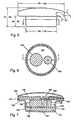
- FIG. 5is an exterior side view of a preferred embodiment showing exemplary dimensions
- FIG. 6is a horizontal sectional view taken substantially along the plane 6 - 6 of FIG. 5 ;
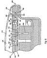
- FIG. 7is a vertical sectional view taken substantially along the plane 7 - 7 of FIG. 6 ;
- FIG. 8is an enlarged sectional view showing a preferred pump/valve assembly in accordance with a first embodiment of the invention.
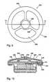
- FIG. 9is a plan view of a second embodiment of the invention incorporating a protective shell around the reservoir
- FIG. 10is a sectional view taken substantially along the plane 10 - 10 of FIG. 9 ;
- FIG. 11is a sectional view of an alternative preferred embodiment of this invention.
- FIG. 1schematically depicts an implantable medication delivery system 20 including a variable volume reservoir 24 for storing medication.
- the reservoir 24is preferably refillable, e.g., via a fill device 26 and tube 28 coupled to a reservoir fill port 30 .
- the fill device 26preferably defines a conical entrance 32 for guiding the needle of a syringe (not shown) through a self healing septum 34 to a channel 36 and check valve 38 .
- the outlet of check valve 38is coupled via nipple 40 to the upstream end of tube 28 .
- the downstream end of tube 28is coupled to the reservoir fill port 30 .
- the variable volume reservoir 24is comprised of a wall 42 including at least a portion supported for movement to enable the reservoir interior volume 44 to expand and contract.
- the reservoir 24is most simply formed of flexible, or flaccid, nonextensible nonporous material forming a sack, it can also be provided in various alternative configurations.
- the reservoir 24can be configured as a bellows, telescoping tubular sections, or as a shaped rubber boot having a stiffened base such that the base lifts and the boot's sidewall rolls upon itself, as the reservoir interior volume changes.
- the reservoir outlet 46is coupled via a fluid passageway 48 to a system output port 50 .
- the system output port 50is typically coupled to a catheter 52 whose downstream end, or tip 54 , is intended to infuse medication into targeted body tissue, e.g., brain tissue, blood or intraperitoneal space.
- the fluid passageway 48is comprised of a first, or upstream, check valve 56 which leads to an entrance port 58 of a pump chamber 60 .
- a pump chamber exit port 62is coupled to a second, or downstream, check valve 64 which leads to the aforementioned system output port 50 .
- the pump chamber 60is defined by a peripheral wall 68 including a movable portion, e.g., a piston or diaphragm 70 .
- the diaphragm 70is coupled to an actuator 72 configured to displace the diaphragm 70 reciprocally between a first position which contracts the volume of the pump chamber 60 and a second position which expands the volume of the chamber 60 .
- the pump chamber 60will expand in volume creating a negative pressure which draws medication from the interior reservoir volume 44 past the check valve 56 into the pump chamber 60 .
- the diaphragm 70moves upwardly, as represented in FIG. 1 , a portion, or dose, of the medication in chamber 60 will be expelled through exit port 62 past check valve 64 to the system output port 50 .
- FIG. 3An isometric exterior view of an exemplary embodiment 80 in accordance with the invention is shown in FIG. 3 .
- the embodiment 80includes a housing 82 carrying an integrated reservoir 84 , analogous to the aforedisccussed reservoir 24 , of FIG. 1 .
- a catheter tube 86analogous to the aforementioned catheter tube 52 , extends outwardly from the housing 82 .
- a fill device 88analogous to aforedisccussed fill device 26 , is coupled to the housing 82 via a fill tube 90 .
- FIG. 4depicts an exemplary embodiment 80 implanted in a patient's body in accordance with one significant application of the invention as a cranial pump for delivering medication to brain tissue.
- Embodiments of the inventioncan be advantageously used in a variety of other applications, e.g., eye, ear, brain.
- FIG. 4represents a patient's skull at 100 covered by a patient's skin 102 and hair 104 .
- a recess 106is surgically formed in the patient's skull for accommodating the housing 82 .
- the reservoir portion 84 of the embodiment 80lies beneath the skin 102 as depicted.
- the fill device 88is also shown as being subcutaneously implanted.
- the subcutaneous fill device 88can be used together with a syringe to fill reservoir 84 with fluid medication.
- FIG. 4also depicts the output catheter 86 extending from the device 80 with the catheter tip 87 positioned to infuse medication into the patient's brain.
- FIGS. 5-11incorporate (1) a safety mechanism for preventing medication flowthrough in the event of a pressure increase in the reservoir, e.g., attributable to a force exerted against the reservoir wall and/or (2) a protective shell around the reservoir to prevent the inadvertent application of a force to the reservoir wall.
- FIG. 2depicts a modification of the ambient pressure reservoir medication delivery system of FIG. 1 to show the inclusion of an exemplary (1) safety mechanism 110 responsive to reservoir pressure via channel 111 and (2) protective reservoir shell 112 .
- the safety mechanism 110 and protective shell 112can be used separately or in combination.
- FIGS. 5-8show the details of a first embodiment of the invention, consistent with the exterior representation shown in FIGS. 3 and 4 , and incorporating the safety mechanism 110 of FIG. 2 .
- FIG. 5comprises an exterior side view of the embodiment depicted in FIG. 3 showing exemplary dimensions (inches) for presently contemplated implant applications.
- the following tableshows exemplary specifications for the applications indicated:
- the medication delivery device depicted in FIGS. 5-8is comprised of a housing 120 formed by a bowl-shaped wall 122 that includes a horizontally oriented (as viewed in FIG. 7 ) circular base 124 having a cylindrical side wall 126 extending vertically therefrom. The upper edge of sidewall 126 flairs radially outward to form a horizontal flange 128 .
- a circular partition plate 130is supported above the base 124 to form a closed compartment for housing a battery 132 (preferably remotely chargeable).
- the upper surface of partition plate 130is preferably used to support an electronic control module 136 and an electrically driven pump actuator 138 , analogous to the aforementioned actuator 72 .
- a substantially planar pump/valve subassembly 140is supported on the upper surface of flange 128 above the module 136 and pump actuator 138 .
- the housing 120 and subassembly 140together form a mounting structure for supporting a reservoir wall 144 of nonextensible nonporous material which extends loosely over the subassembly 140 .
- the peripheral edge 146 of wall 144is preferably sealed to the under surface of flange 128 to thus form a closed reservoir volume 148 above the upper surface of subassembly 140 for storing fluid medication.
- the pump/valve subassembly 140preferably comprises a thin flat structure formed by laminating two or more plates 152 , 154 .
- the laminated platescan be formed and assembled using a variety of materials, e.g., titanium, stainless steel, silicon, plastic, etc. and known fabrication techniques appropriate to the materials and the desired dimensions and tolerances.
- upper plate 152defines an inlet port 160 of a fluid passageway 161 leading to an outlet port 164 .
- the fluid passageway 161includes a first check valve 166 , located just downstream form inlet port 160 .
- Check valve 166is preferably comprised of spring 170 that normally seals a precision ball 172 against valve seat 174 .
- the outlet of check valve 166opens via port 175 to pump chamber 176 whose peripheral wall is defined in part by flexible diaphragm 178 .
- the pump chamber outlet 179leads to the inlet of a second check valve 180 preferably comprised of spring 182 normally sealing ball 184 against valve seat 186 .
- the pump diaphragm 178is mounted for movement, as by coupling it to a stem 188 of the linear actuator 138 .
- the actuator 138pulls the stem downward (as viewed in FIG. 8 ) to increase the volume of pump chamber 176 , the resulting suction draws medication past check valve 166 into the pump chamber 176 .
- the actuator 138drives the stem 188 upward, the diaphragm 178 produces a positive pressure to expel medication from the pump chamber 176 past the second check valve 180 toward the outlet port 164 .
- the actuatorhas been described as pulling the stem downward and driving the stem upward. It should be understood however, that the diaphragm could, in fact, be biased to one position so that the actuator need only move it from the biased position
- Safety valve 196is preferably comprised of a flexible, e.g., elastomeric, valve disc 198 mounted so that its upper surface normally seals against the valve seat 200 (flow-block position) in the absence of a force produced by an upward stroke of diaphragm 178 . More particularly, When the actuator 138 is dormant, the upper face of valve disc 198 is exposed to ambient reservoir pressure via check valves 166 and 168 . The lower face of valve disc 198 is also exposed to ambient reservoir pressure via channel 204 , analogous to channel 111 of FIG. 2 . Parenthetically, note also that channel 204 defines a path from fill nipple 206 , analogous to input 30 of FIG. 1 , to the reservoir volume interior 148 .
- valve disc 198Under normal conditions with the actuator 138 dormant, ambient reservoir pressure is applied to both faces of valve disc 198 and it remains in a flow-block position sealed against valve seat 200 so as to block outflow from check valve 180 to output port 164 . If the reservoir pressure increases, e.g., attributable to the patient being bumped or pressing the reservoir wall, the pressure will increase equally on both faces of the valve disc 198 , thereby leaving the disc 198 seated. Thus, the inclusion of safety valve 196 upstream from outlet port 164 prevents a failure mode which could, in the absence of the safety valve, unintentionally force medication out through the outlet port 164 .
- valve disc 198When the actuator 138 is activated, however, the upward movement of diaphragm 178 forces medication from the pump chamber 176 past the check valve 180 to the upper face of valve disc 198 . The resulting unbalanced pressure on valve disc 198 unseats the disc thereby disabling its flow blocking function to permit medication to flow therepast to the outlet port 164 .
- FIGS. 9 and 10illustrate a preferred protective shell 240 (corresponding to shell 112 of FIG. 2 ) configured to protect the reservoir wall 144 from impact, while still exposing it to ambient pressure and allowing it to expand and contract.
- the shell 240preferably comprises a dome-shaped rigid or semi-rigid frame 242 including a hub 244 and radial arms 246 extending to an outer ring 248 .
- the outer ring 248carries inwardly extending flange portions 250 configured to mount around housing flange 128 .
- the shell 240is shaped and dimensioned to define an interior volume 252 able to snugly accommodate reservoir wall 144 in its fully expanded state.
- a diffusive membrane 258preferably formed of a cellulose acetate or similar material, is mounted between the hub 244 and outer ring 248 .
- the diffusive membrane materialis preferably selected to permit slow diffusion of body fluids into the volume 252 while preventing the in-growth of body tissue. A slow rate of fluid inflow is acceptable because, in typical applications, the reservoir will contract at a maximum rate of only about 40 milliliters per month.
- an outflow check valve 264is preferably mounted in the hub 244 to allow the reservoir to expand relatively rapidly and force fluid out of the volume 252 .
- Check valve 264is comprised of a stem 266 carrying a retention rod 268 on its lower end and a sealing disc 270 on its upper end. When the reservoir expands, it increases the pressure in volume 252 to lift disk 270 permitting the outflow of fluid through opening 272 around stem 266 .
- FIG. 11schematically illustrates an alternative preferred medication delivery device 300 in accordance with the present invention.
- the device 300is comprised of a housing 302 including a top cover plate 304 and a bottom plate 306 .
- the spaced plates 304 , 306define an interior compartment 308 for housing a battery 310 , electronics 312 , and a pump 314 .
- the housing 302 and plate 306form a mounting structure for supporting a flexible membrane 316 .
- the membrane 316preferably comprises flaccid nonextensible nonporous material which acts as a peripheral wall 318 enclosing an interior reservoir volume 320 .
- the spaced plates 304 , 306support a reservoir fill port 324 which includes a self healing septum 326 .
- the reservoir volume 320can be filled by a hypodermic needle (not shown) penetrating the septum 326 and discharging medication through chamber 328 and ports 329 formed in plate 306 .
- the plate 306functions as part of a pump/valve subassembly 330 which includes a fluid transfer passageway for coupling reservoir volume 320 to outlet port 332 . More particularly, plate 306 defines inlet port 336 opening via check valve 338 into pump chamber 340 . Pump chamber 340 exits past outlet check valve 342 to safety valve 348 .
- Safety valve 348includes a valve element or diaphragm 350 having one face 352 exposed via port 354 to the pressure in reservoir volume 320 . A second face 354 of diaphragm 350 is exposed via check valve 342 to the pressure produced in pump chamber 340 .
- an implantable ambient pressure medication delivery systemincluding means for preventing the unintended discharge of medication into the patient's body.
- the described meansincludes a safety mechanism depicted primarily in the embodiments of FIGS. 5-8 and 11 and a protective shell depicted primarily in FIGS. 9 and 10 . Although distinctly discussed, it should be understood that these two techniques can be employed separately or in combination.
- check valves and safety valve illustratedcould take many alternative forms using different valve elements and different mechanisms for producing the seating force, e.g., magnetic.
Landscapes
- Health & Medical Sciences (AREA)
- Vascular Medicine (AREA)
- Engineering & Computer Science (AREA)
- Anesthesiology (AREA)
- Biomedical Technology (AREA)
- Heart & Thoracic Surgery (AREA)
- Hematology (AREA)
- Life Sciences & Earth Sciences (AREA)
- Animal Behavior & Ethology (AREA)
- General Health & Medical Sciences (AREA)
- Public Health (AREA)
- Veterinary Medicine (AREA)
- Infusion, Injection, And Reservoir Apparatuses (AREA)
- Media Introduction/Drainage Providing Device (AREA)
Abstract
Description
| Very Small Pump; Very Low Delivery Rate | Small Pump; Low Delivery Rate | |
| Parameter | Typical | Min | Max | Typical | Min | Max |
| Medication | 3 | 0.5 | 5 | 20 | 5 | 40 |
| Reservoir | ||||||
| Volume (ml) | ||||||
| Daily Delivery Rate | 0.05 | 0.03 | 0.1 | 0.33 | 0.1 | 0.66 |
| (ml/day) | ||||||
| Maximum Delivery | 3 | 1 | 10 | 30 | 5 | 120 |
| Rate | ||||||
| (ul/minute) | ||||||
| Stroke Volume | 0.2 | 0.05 | 1 | 0.5 | 0.1 | 5 |
| (microliters) | ||||||
| Maximum Output | 14.7 | 7 | 100 | 14.7 | 7 | 100 |
| Pressure (psig) | ||||||
| Longevity (years) | 8 | 3 | 10 | 8 | 3 | 10 |
| Refill Interval (days) | 60 | 30 | 90 | 60 | 30 | 90 |
| Application (typical) | Tinnitus using lidocaine | Pain using morphine; |
| Spasticity (CP) using baclofen | ||
| Route of Delivery | Intracranial, eye, ear | Intrathecal, epidural, |
| Intraperitoneal, systemic | ||
Claims (12)
Priority Applications (1)
| Application Number | Priority Date | Filing Date | Title |
|---|---|---|---|
| US10/515,152US8425493B2 (en) | 2002-05-22 | 2003-05-20 | Implantable medication delivery device |
Applications Claiming Priority (3)
| Application Number | Priority Date | Filing Date | Title |
|---|---|---|---|
| US38323702P | 2002-05-22 | 2002-05-22 | |
| PCT/US2003/016329WO2003099351A2 (en) | 2002-05-22 | 2003-05-20 | Implantable medication delivery device |
| US10/515,152US8425493B2 (en) | 2002-05-22 | 2003-05-20 | Implantable medication delivery device |
Publications (2)
| Publication Number | Publication Date |
|---|---|
| US20060122578A1 US20060122578A1 (en) | 2006-06-08 |
| US8425493B2true US8425493B2 (en) | 2013-04-23 |
Family
ID=29584529
Family Applications (1)
| Application Number | Title | Priority Date | Filing Date |
|---|---|---|---|
| US10/515,152Active2028-10-19US8425493B2 (en) | 2002-05-22 | 2003-05-20 | Implantable medication delivery device |
Country Status (4)
| Country | Link |
|---|---|
| US (1) | US8425493B2 (en) |
| EP (1) | EP1509278B1 (en) |
| AU (1) | AU2003243305A1 (en) |
| WO (1) | WO2003099351A2 (en) |
Cited By (3)
| Publication number | Priority date | Publication date | Assignee | Title |
|---|---|---|---|---|
| US20180344925A1 (en)* | 2016-01-06 | 2018-12-06 | Vicentra B.V. | Pumping chamber with rib |
| US11135354B2 (en) | 2014-03-03 | 2021-10-05 | Quasuras, Inc. | Fluid delivery pump |
| US11504472B2 (en)* | 2017-07-06 | 2022-11-22 | Quasuras, Inc. | Medical pump with flow control |
Families Citing this family (62)
| Publication number | Priority date | Publication date | Assignee | Title |
|---|---|---|---|---|
| EP1635894B1 (en)* | 2003-06-25 | 2015-05-27 | Infusion Systems, LLC | Medication infusion device using negatively biased ambient pressure medication chamber |
| FR2860438B1 (en)* | 2003-10-07 | 2006-06-02 | Jean Marie Podvin | IMPLANTABLE PERFUSION DEVICE |
| US7867194B2 (en) | 2004-01-29 | 2011-01-11 | The Charles Stark Draper Laboratory, Inc. | Drug delivery apparatus |
| US7766885B2 (en) | 2004-06-07 | 2010-08-03 | Medtronic, Inc. | Drug delivery system |
| US20080281250A1 (en)* | 2005-05-10 | 2008-11-13 | Marvin Bergsneider | Self-Clearing Catheter for Clinical Implantation |
| US12370305B2 (en) | 2006-02-09 | 2025-07-29 | Deka Products Limited Partnership | Patch-sized fluid delivery systems and methods |
| US12151080B2 (en) | 2006-02-09 | 2024-11-26 | Deka Products Limited Partnership | Adhesive and peripheral systems and methods for medical devices |
| US11497846B2 (en) | 2006-02-09 | 2022-11-15 | Deka Products Limited Partnership | Patch-sized fluid delivery systems and methods |
| US10010669B2 (en) | 2006-02-09 | 2018-07-03 | Deka Products Limited Partnership | Systems and methods for fluid delivery |
| US12070574B2 (en) | 2006-02-09 | 2024-08-27 | Deka Products Limited Partnership | Apparatus, systems and methods for an infusion pump assembly |
| EP3165247B1 (en) | 2006-02-09 | 2020-10-28 | DEKA Products Limited Partnership | Pumping fluid delivery systems and methods using force application assembley |
| US11478623B2 (en) | 2006-02-09 | 2022-10-25 | Deka Products Limited Partnership | Infusion pump assembly |
| US11364335B2 (en) | 2006-02-09 | 2022-06-21 | Deka Products Limited Partnership | Apparatus, system and method for fluid delivery |
| US12274857B2 (en) | 2006-02-09 | 2025-04-15 | Deka Products Limited Partnership | Method and system for shape-memory alloy wire control |
| US11027058B2 (en) | 2006-02-09 | 2021-06-08 | Deka Products Limited Partnership | Infusion pump assembly |
| US8579884B2 (en) | 2006-02-09 | 2013-11-12 | Deka Products Limited Partnership | Infusion pump assembly |
| US8323267B2 (en) | 2006-04-27 | 2012-12-04 | Medtronic, Inc. | Infusion device with active and passive check valves |
| US8221354B2 (en)* | 2006-04-27 | 2012-07-17 | Medtronic, Inc. | Infusion device with positive pressure elastic bladder reservoir |
| US7867221B2 (en) | 2006-04-27 | 2011-01-11 | Medtronic, Inc. | Infusion device and overfill protection mechanism for use with same |
| GB0623395D0 (en) | 2006-11-23 | 2007-01-03 | Renishaw Plc | Port |
| WO2008094672A2 (en) | 2007-01-31 | 2008-08-07 | Charles Stark Draper Laboratory, Inc. | Membrane-based fluid control in microfluidic devices |
| CA2677667A1 (en) | 2007-02-09 | 2008-08-14 | Deka Products Limited Partnership | Automated insertion assembly |
| US20090069743A1 (en)* | 2007-09-11 | 2009-03-12 | Baxter International Inc. | Infusion therapy sensor system |
| WO2009065427A1 (en)* | 2007-11-23 | 2009-05-28 | Fraunhofer-Gesellschaft zur Förderung der angewandten Forschung e.V. | Pump arrangement having safety valve |
| US9456955B2 (en) | 2007-12-31 | 2016-10-04 | Deka Products Limited Partnership | Apparatus, system and method for fluid delivery |
| US8900188B2 (en) | 2007-12-31 | 2014-12-02 | Deka Products Limited Partnership | Split ring resonator antenna adapted for use in wirelessly controlled medical device |
| CA2919786C (en) | 2007-12-31 | 2019-10-22 | Deka Products Limited Partnership | Infusion pump assembly |
| US9526830B2 (en) | 2007-12-31 | 2016-12-27 | Deka Products Limited Partnership | Wearable pump assembly |
| US10188787B2 (en) | 2007-12-31 | 2019-01-29 | Deka Products Limited Partnership | Apparatus, system and method for fluid delivery |
| US8881774B2 (en) | 2007-12-31 | 2014-11-11 | Deka Research & Development Corp. | Apparatus, system and method for fluid delivery |
| US10080704B2 (en) | 2007-12-31 | 2018-09-25 | Deka Products Limited Partnership | Apparatus, system and method for fluid delivery |
| US9023063B2 (en) | 2008-04-17 | 2015-05-05 | Apollo Endosurgery, Inc. | Implantable access port device having a safety cap |
| BRPI0910460A2 (en) | 2008-04-17 | 2018-02-14 | Allergan Inc | implantable access door device and fastening system |
| CN102014982B (en) | 2008-05-02 | 2014-03-26 | 凯希特许有限公司 | Manually actuated reduced pressure therapy pump with adjustable pressure capability |
| EP2370125B1 (en) | 2008-10-07 | 2019-04-10 | Roche Diabetes Care GmbH | Skin securable drug delivery device with a shock absorbing protective shield |
| US8632497B2 (en) | 2008-10-09 | 2014-01-21 | Roche Diagnostics Operations Inc. | Skin securable drug delivery device with a shock absorbing protective shield |
| WO2011008966A2 (en) | 2009-07-15 | 2011-01-20 | Deka Products Limited Partnership | Apparatus, systems and methods for an infusion pump assembly |
| US8708979B2 (en) | 2009-08-26 | 2014-04-29 | Apollo Endosurgery, Inc. | Implantable coupling device |
| US8506532B2 (en) | 2009-08-26 | 2013-08-13 | Allergan, Inc. | System including access port and applicator tool |
| US8715158B2 (en) | 2009-08-26 | 2014-05-06 | Apollo Endosurgery, Inc. | Implantable bottom exit port |
| EP2519288B1 (en) | 2009-12-31 | 2016-04-13 | DEKA Products Limited Partnership | Infusion pump assembley |
| CA3033439C (en) | 2010-01-22 | 2021-04-06 | Deka Products Limited Partnership | Method and system for shape-memory alloy wire control |
| US8882728B2 (en) | 2010-02-10 | 2014-11-11 | Apollo Endosurgery, Inc. | Implantable injection port |
| GB201002370D0 (en) | 2010-02-12 | 2010-03-31 | Renishaw Ireland Ltd | Percutaneous drug delivery apparatus |
| US8992415B2 (en) | 2010-04-30 | 2015-03-31 | Apollo Endosurgery, Inc. | Implantable device to protect tubing from puncture |
| US20110270025A1 (en) | 2010-04-30 | 2011-11-03 | Allergan, Inc. | Remotely powered remotely adjustable gastric band system |
| US20110270021A1 (en) | 2010-04-30 | 2011-11-03 | Allergan, Inc. | Electronically enhanced access port for a fluid filled implant |
| US20120041258A1 (en) | 2010-08-16 | 2012-02-16 | Allergan, Inc. | Implantable access port system |
| US20120065460A1 (en) | 2010-09-14 | 2012-03-15 | Greg Nitka | Implantable access port system |
| CA2825757C (en) | 2011-02-02 | 2019-09-03 | The Charles Stark Draper Laboratory, Inc. | Drug delivery apparatus |
| US8821373B2 (en) | 2011-05-10 | 2014-09-02 | Apollo Endosurgery, Inc. | Directionless (orientation independent) needle injection port |
| US8801597B2 (en) | 2011-08-25 | 2014-08-12 | Apollo Endosurgery, Inc. | Implantable access port with mesh attachment rivets |
| US9199069B2 (en) | 2011-10-20 | 2015-12-01 | Apollo Endosurgery, Inc. | Implantable injection port |
| US8858421B2 (en) | 2011-11-15 | 2014-10-14 | Apollo Endosurgery, Inc. | Interior needle stick guard stems for tubes |
| US9089395B2 (en) | 2011-11-16 | 2015-07-28 | Appolo Endosurgery, Inc. | Pre-loaded septum for use with an access port |
| US11524151B2 (en) | 2012-03-07 | 2022-12-13 | Deka Products Limited Partnership | Apparatus, system and method for fluid delivery |
| US20130345668A1 (en)* | 2012-06-20 | 2013-12-26 | Cook Medical Technologies Llc | Skin securable infusion assembly and method of use |
| US9617020B2 (en) | 2013-07-03 | 2017-04-11 | Deka Products Limited Partnership | Apparatus, system and method for fluid delivery |
| AU2016316683B2 (en) | 2015-09-04 | 2020-07-23 | The Johns Hopkins University | Low-profile intercranial device |
| US20170095610A1 (en)* | 2015-10-06 | 2017-04-06 | Medtronic Minimed, Inc. | Personal injection device |
| CA3098372A1 (en) | 2018-04-24 | 2019-10-31 | Deka Products Limited Partnership | Apparatus and system for fluid delivery |
| KR102424862B1 (en)* | 2020-01-28 | 2022-07-26 | 투바이오스 주식회사 | Implantable and Manually-controllable Drug Delivery Device |
Citations (12)
| Publication number | Priority date | Publication date | Assignee | Title |
|---|---|---|---|---|
| US4265600A (en) | 1978-09-05 | 1981-05-05 | Harold Mandroian | Pump apparatus |
| US4265601A (en) | 1978-09-05 | 1981-05-05 | Harold Mandroian | Three valve precision pump apparatus with head pressure flowthrough protection |
| US4548607A (en)* | 1983-04-13 | 1985-10-22 | Cordis Corporation | Implantable manually actuated medication dispensing system |
| US4594058A (en) | 1984-06-01 | 1986-06-10 | The Johns Hopkins University | Single valve diaphragm pump with decreased sensitivity to ambient conditions |
| US4668231A (en)* | 1984-02-15 | 1987-05-26 | Cordis Corporation | Implantable hand-operable dispensers for fluid medicaments |
| US5704520A (en) | 1993-07-19 | 1998-01-06 | Elan Medical Technologies, Limited | Liquid material dispenser and valve |
| WO1999038551A1 (en) | 1998-02-02 | 1999-08-05 | Medtronic, Inc. | Implantable drug infusion device having a safety valve |
| US5954058A (en) | 1995-09-01 | 1999-09-21 | Strato/Infusaid, Inc. | Power supply for implantable device |
| US5957890A (en) | 1997-06-09 | 1999-09-28 | Minimed Inc. | Constant flow medication infusion pump |
| WO2001058506A2 (en) | 2000-02-10 | 2001-08-16 | Power Paper Ltd. | Drug delivery device and method |
| US6280416B1 (en) | 1999-02-19 | 2001-08-28 | Minimed Inc. | Constant flow medication infusion pump |
| US6656158B2 (en) | 2002-04-23 | 2003-12-02 | Insulet Corporation | Dispenser for patient infusion device |
- 2003
- 2003-05-20EPEP03755456.5Apatent/EP1509278B1/ennot_activeExpired - Lifetime
- 2003-05-20WOPCT/US2003/016329patent/WO2003099351A2/ennot_activeApplication Discontinuation
- 2003-05-20AUAU2003243305Apatent/AU2003243305A1/ennot_activeAbandoned
- 2003-05-20USUS10/515,152patent/US8425493B2/enactiveActive
Patent Citations (12)
| Publication number | Priority date | Publication date | Assignee | Title |
|---|---|---|---|---|
| US4265600A (en) | 1978-09-05 | 1981-05-05 | Harold Mandroian | Pump apparatus |
| US4265601A (en) | 1978-09-05 | 1981-05-05 | Harold Mandroian | Three valve precision pump apparatus with head pressure flowthrough protection |
| US4548607A (en)* | 1983-04-13 | 1985-10-22 | Cordis Corporation | Implantable manually actuated medication dispensing system |
| US4668231A (en)* | 1984-02-15 | 1987-05-26 | Cordis Corporation | Implantable hand-operable dispensers for fluid medicaments |
| US4594058A (en) | 1984-06-01 | 1986-06-10 | The Johns Hopkins University | Single valve diaphragm pump with decreased sensitivity to ambient conditions |
| US5704520A (en) | 1993-07-19 | 1998-01-06 | Elan Medical Technologies, Limited | Liquid material dispenser and valve |
| US5954058A (en) | 1995-09-01 | 1999-09-21 | Strato/Infusaid, Inc. | Power supply for implantable device |
| US5957890A (en) | 1997-06-09 | 1999-09-28 | Minimed Inc. | Constant flow medication infusion pump |
| WO1999038551A1 (en) | 1998-02-02 | 1999-08-05 | Medtronic, Inc. | Implantable drug infusion device having a safety valve |
| US6280416B1 (en) | 1999-02-19 | 2001-08-28 | Minimed Inc. | Constant flow medication infusion pump |
| WO2001058506A2 (en) | 2000-02-10 | 2001-08-16 | Power Paper Ltd. | Drug delivery device and method |
| US6656158B2 (en) | 2002-04-23 | 2003-12-02 | Insulet Corporation | Dispenser for patient infusion device |
Non-Patent Citations (2)
| Title |
|---|
| D Accoto, et al., Modelling of micropumps using unimorph piezoelectric actuator and ball valves, J. Micromech. Microeng, 10 (2000) 277-281, IOP Publishing Ltd, UK. |
| Supp. Search Report Dated Jul. 23, 2008 in EPO App. Ser. No. 03 755 456.5. |
Cited By (5)
| Publication number | Priority date | Publication date | Assignee | Title |
|---|---|---|---|---|
| US11135354B2 (en) | 2014-03-03 | 2021-10-05 | Quasuras, Inc. | Fluid delivery pump |
| US20180344925A1 (en)* | 2016-01-06 | 2018-12-06 | Vicentra B.V. | Pumping chamber with rib |
| US10682461B2 (en)* | 2016-01-06 | 2020-06-16 | Vicentra B. V. | Pumping chamber with rib |
| US11504472B2 (en)* | 2017-07-06 | 2022-11-22 | Quasuras, Inc. | Medical pump with flow control |
| US12178998B2 (en) | 2017-07-06 | 2024-12-31 | Quasuras, Inc. | Medical pump with flow control |
Also Published As
| Publication number | Publication date |
|---|---|
| AU2003243305A1 (en) | 2003-12-12 |
| US20060122578A1 (en) | 2006-06-08 |
| EP1509278B1 (en) | 2014-03-12 |
| AU2003243305A8 (en) | 2003-12-12 |
| WO2003099351A3 (en) | 2004-07-01 |
| EP1509278A2 (en) | 2005-03-02 |
| WO2003099351A2 (en) | 2003-12-04 |
| EP1509278A4 (en) | 2008-08-20 |
Similar Documents
| Publication | Publication Date | Title |
|---|---|---|
| US8425493B2 (en) | Implantable medication delivery device | |
| US4898584A (en) | Implantable patient-activated fluid delivery device | |
| US5053031A (en) | Pump infusion system | |
| US4898585A (en) | Implantable patient-activated fluid delivery device with bolus injection port | |
| CA2054148C (en) | Liquid-vapor pressure reservoir for medication infusion pump | |
| US5586629A (en) | Presure controlled system for filling an implantable drug infusion pump | |
| US5176644A (en) | Medication infusion pump with improved liquid-vapor pressure reservoir | |
| EP0998317B1 (en) | Inlet port for a medication infusion pump | |
| US7510552B2 (en) | Implantable medication delivery device using pressure regulator | |
| CA1152823A (en) | Implantable drug infusion regulator | |
| US7108686B2 (en) | Implantable, refillable infusion device and septum replacement kit | |
| US4193397A (en) | Infusion apparatus and method | |
| US6666845B2 (en) | Implantable infusion pump | |
| EP0291612B1 (en) | Implantable pump. | |
| US20240252743A1 (en) | Implantable continuous-flow pumps | |
| WO2002068013A2 (en) | Multiple canopy | |
| US4898583A (en) | Implantable patient-activated fluid delivery device and outlet valve therefor | |
| EP3400039B1 (en) | Pumping chamber with rib | |
| GB2131496A (en) | Apparatus for dispensing infusate to a mammal body | |
| CA1333144C (en) | Implantable drug delivery system |
Legal Events
| Date | Code | Title | Description |
|---|---|---|---|
| AS | Assignment | Owner name:ADVANCED BIONICS CORPORATION, CALIFORNIA Free format text:ASSIGNMENT OF ASSIGNORS INTEREST;ASSIGNORS:NASON, CLYDE K.;DAS, STEPHEN D.;LORD, PETER C.;AND OTHERS;SIGNING DATES FROM 20060915 TO 20061011;REEL/FRAME:018392/0866 Owner name:ADVANCED BIONICS CORPORATION, CALIFORNIA Free format text:ASSIGNMENT OF ASSIGNORS INTEREST;ASSIGNORS:NASON, CLYDE K.;DAS, STEPHEN D.;LORD, PETER C.;AND OTHERS;REEL/FRAME:018392/0866;SIGNING DATES FROM 20060915 TO 20061011 | |
| AS | Assignment | Owner name:INFUSION SYSTEMS, LLC, CALIFORNIA Free format text:ASSIGNMENT OF ASSIGNORS INTEREST;ASSIGNOR:BOSTON SCIENTIFIC NEUROMODULATION CORPORATION;REEL/FRAME:020329/0853 Effective date:20080107 | |
| AS | Assignment | Owner name:BOSTON SCIENTIFIC NEUROMODULATION CORPORATION, CAL Free format text:CHANGE OF NAME;ASSIGNOR:ADVANCED BIONICS CORPORATION;REEL/FRAME:020796/0264 Effective date:20071116 | |
| AS | Assignment | Owner name:ALFRED E. MANN FOUNDATION FOR SCIENTIFIC RESEARCH, Free format text:ASSIGNMENT OF ASSIGNORS INTEREST;ASSIGNOR:INFUSION SYSTEMS, LLC;REEL/FRAME:025429/0383 Effective date:20091229 | |
| STCF | Information on status: patent grant | Free format text:PATENTED CASE | |
| AS | Assignment | Owner name:ALFRED E. MANN FOUNDATION FOR SCIENTIFIC RESEARCH, Free format text:SECURITY INTEREST;ASSIGNOR:MEDALLION THERAPEUTICS, INC.;REEL/FRAME:032815/0188 Effective date:20140331 | |
| AS | Assignment | Owner name:ALFRED E. MANN FOUNDATION FOR SCIENTIFIC RESEARCH, Free format text:CORRECTIVE ASSIGNMENT TO CORRECT THE SCHEDULE WHICH REFLECTED PATENT NUMBER AS 8,327,041 AND SHOULD HAVE BEEN REFLECTED AS 8,372,041. PREVIOUSLY RECORDED ON REEL 032815 FRAME 0188. ASSIGNOR(S) HEREBY CONFIRMS THE SECURITY INTEREST;ASSIGNOR:MEDALLION THERAPEUTICS, INC.;REEL/FRAME:032827/0478 Effective date:20140331 | |
| AS | Assignment | Owner name:MEDALLION THERAPEUTICS, INC., CALIFORNIA Free format text:ASSIGNMENT OF ASSIGNORS INTEREST;ASSIGNOR:ALFRED E. MANN FOUNDATION FOR SCIENTIFIC RESEARCH;REEL/FRAME:032892/0067 Effective date:20140331 | |
| FPAY | Fee payment | Year of fee payment:4 | |
| AS | Assignment | Owner name:THE ALFRED E. MANN FOUNDATION FOR SCIENTIFIC RESEA Free format text:ASSIGNMENT OF ASSIGNORS INTEREST;ASSIGNOR:MEDALLION THERAPEUTICS, INC.;REEL/FRAME:051287/0120 Effective date:20191210 Owner name:THE ALFRED E. MANN FOUNDATION FOR SCIENTIFIC RESEARCH, CALIFORNIA Free format text:ASSIGNMENT OF ASSIGNORS INTEREST;ASSIGNOR:MEDALLION THERAPEUTICS, INC.;REEL/FRAME:051287/0120 Effective date:20191210 | |
| MAFP | Maintenance fee payment | Free format text:PAYMENT OF MAINTENANCE FEE, 8TH YR, SMALL ENTITY (ORIGINAL EVENT CODE: M2552); ENTITY STATUS OF PATENT OWNER: SMALL ENTITY Year of fee payment:8 | |
| AS | Assignment | Owner name:MEDTRONIC MINIMED, INC., MINNESOTA Free format text:ASSIGNMENT OF ASSIGNORS INTEREST;ASSIGNOR:THE ALFRED E. MANN FOUNDATION FOR SCIENTIFIC RESEARCH;REEL/FRAME:057962/0741 Effective date:20210706 | |
| FEPP | Fee payment procedure | Free format text:ENTITY STATUS SET TO UNDISCOUNTED (ORIGINAL EVENT CODE: BIG.); ENTITY STATUS OF PATENT OWNER: LARGE ENTITY | |
| MAFP | Maintenance fee payment | Free format text:PAYMENT OF MAINTENANCE FEE, 12TH YEAR, LARGE ENTITY (ORIGINAL EVENT CODE: M1553); ENTITY STATUS OF PATENT OWNER: LARGE ENTITY Year of fee payment:12 | |
| AS | Assignment | Owner name:MEDTRONIC MINIMED, INC., CALIFORNIA Free format text:RELEASE BY SECURED PARTY;ASSIGNOR:THE ALFRED E. MANN FOUNDATION FOR SCIENTIFIC RESEARCH;REEL/FRAME:071698/0639 Effective date:20250523 |