US8425455B2 - Bronchial catheter and method of use - Google Patents
Bronchial catheter and method of useDownload PDFInfo
- Publication number
- US8425455B2 US8425455B2US13/074,536US201113074536AUS8425455B2US 8425455 B2US8425455 B2US 8425455B2US 201113074536 AUS201113074536 AUS 201113074536AUS 8425455 B2US8425455 B2US 8425455B2
- Authority
- US
- United States
- Prior art keywords
- catheter
- sealing
- lumen
- balloon
- bronchial
- Prior art date
- Legal status (The legal status is an assumption and is not a legal conclusion. Google has not performed a legal analysis and makes no representation as to the accuracy of the status listed.)
- Expired - Fee Related, expires
Links
- 238000000034methodMethods0.000titleclaimsabstractdescription82
- 210000004072lungAnatomy0.000claimsabstractdescription129
- 238000007789sealingMethods0.000claimsabstractdescription77
- 238000003780insertionMethods0.000claimsabstractdescription33
- 230000037431insertionEffects0.000claimsabstractdescription33
- 210000000621bronchiAnatomy0.000claimsdescription103
- 239000012530fluidSubstances0.000claimsdescription94
- 238000000502dialysisMethods0.000claimsdescription57
- 210000003437tracheaAnatomy0.000claimsdescription35
- 238000001802infusionMethods0.000claimsdescription24
- 238000011282treatmentMethods0.000claimsdescription18
- 238000004891communicationMethods0.000claimsdescription10
- 230000003601intercostal effectEffects0.000claimsdescription8
- XLYOFNOQVPJJNP-UHFFFAOYSA-NwaterSubstancesOXLYOFNOQVPJJNP-UHFFFAOYSA-N0.000claimsdescription7
- WQZGKKKJIJFFOK-GASJEMHNSA-NGlucoseNatural productsOC[C@H]1OC(O)[C@H](O)[C@@H](O)[C@@H]1OWQZGKKKJIJFFOK-GASJEMHNSA-N0.000claimsdescription6
- DGAQECJNVWCQMB-PUAWFVPOSA-MIlexoside XXIXChemical compoundC[C@@H]1CC[C@@]2(CC[C@@]3(C(=CC[C@H]4[C@]3(CC[C@@H]5[C@@]4(CC[C@@H](C5(C)C)OS(=O)(=O)[O-])C)C)[C@@H]2[C@]1(C)O)C)C(=O)O[C@H]6[C@@H]([C@H]([C@@H]([C@H](O6)CO)O)O)O.[Na+]DGAQECJNVWCQMB-PUAWFVPOSA-M0.000claimsdescription6
- ZLMJMSJWJFRBEC-UHFFFAOYSA-NPotassiumChemical compound[K]ZLMJMSJWJFRBEC-UHFFFAOYSA-N0.000claimsdescription6
- 239000011575calciumSubstances0.000claimsdescription6
- 239000011591potassiumSubstances0.000claimsdescription6
- 229910052700potassiumInorganic materials0.000claimsdescription6
- 239000011734sodiumSubstances0.000claimsdescription6
- 229910052708sodiumInorganic materials0.000claimsdescription6
- OYPRJOBELJOOCE-UHFFFAOYSA-NCalciumChemical compound[Ca]OYPRJOBELJOOCE-UHFFFAOYSA-N0.000claimsdescription5
- 229910052791calciumInorganic materials0.000claimsdescription5
- 239000011777magnesiumSubstances0.000claimsdescription5
- QTBSBXVTEAMEQO-UHFFFAOYSA-MAcetateChemical compoundCC([O-])=OQTBSBXVTEAMEQO-UHFFFAOYSA-M0.000claimsdescription4
- FYYHWMGAXLPEAU-UHFFFAOYSA-NMagnesiumChemical compound[Mg]FYYHWMGAXLPEAU-UHFFFAOYSA-N0.000claimsdescription4
- 239000008121dextroseSubstances0.000claimsdescription4
- 239000003814drugSubstances0.000claimsdescription4
- 229910052749magnesiumInorganic materials0.000claimsdescription4
- BVKZGUZCCUSVTD-UHFFFAOYSA-MBicarbonateChemical compoundOC([O-])=OBVKZGUZCCUSVTD-UHFFFAOYSA-M0.000claimsdescription3
- VEXZGXHMUGYJMC-UHFFFAOYSA-MChloride anionChemical compound[Cl-]VEXZGXHMUGYJMC-UHFFFAOYSA-M0.000claimsdescription3
- 210000001124body fluidAnatomy0.000claimsdescription3
- 230000004044responseEffects0.000claimsdescription3
- 210000003708urethraAnatomy0.000claimsdescription3
- 239000002872contrast mediaSubstances0.000claims1
- 239000000243solutionSubstances0.000description31
- 239000000463materialSubstances0.000description22
- 210000004303peritoneumAnatomy0.000description11
- UIIMBOGNXHQVGW-UHFFFAOYSA-MSodium bicarbonateChemical compound[Na+].OC([O-])=OUIIMBOGNXHQVGW-UHFFFAOYSA-M0.000description10
- 230000001419dependent effectEffects0.000description10
- 239000007789gasSubstances0.000description10
- 210000004379membraneAnatomy0.000description10
- 239000012528membraneSubstances0.000description10
- 239000008280bloodSubstances0.000description9
- 210000004369bloodAnatomy0.000description9
- -1constructionsSubstances0.000description9
- 210000001519tissueAnatomy0.000description9
- 238000013461designMethods0.000description8
- 230000006870functionEffects0.000description7
- 230000003068static effectEffects0.000description7
- 210000000115thoracic cavityAnatomy0.000description7
- 239000003570airSubstances0.000description6
- 230000000712assemblyEffects0.000description6
- 238000000429assemblyMethods0.000description6
- WQZGKKKJIJFFOK-VFUOTHLCSA-Nbeta-D-glucoseChemical compoundOC[C@H]1O[C@@H](O)[C@H](O)[C@@H](O)[C@@H]1OWQZGKKKJIJFFOK-VFUOTHLCSA-N0.000description6
- 229960001031glucoseDrugs0.000description6
- 208000015181infectious diseaseDiseases0.000description6
- 210000003200peritoneal cavityAnatomy0.000description6
- 210000003281pleural cavityAnatomy0.000description6
- FAPWRFPIFSIZLT-UHFFFAOYSA-MSodium chlorideChemical compound[Na+].[Cl-]FAPWRFPIFSIZLT-UHFFFAOYSA-M0.000description5
- 210000003484anatomyAnatomy0.000description5
- 238000000576coating methodMethods0.000description5
- 230000000670limiting effectEffects0.000description5
- 239000000203mixtureSubstances0.000description5
- 229920001296polysiloxanePolymers0.000description5
- 230000008569processEffects0.000description5
- 229910000030sodium bicarbonateInorganic materials0.000description5
- TWRXJAOTZQYOKJ-UHFFFAOYSA-LMagnesium chlorideChemical compound[Mg+2].[Cl-].[Cl-]TWRXJAOTZQYOKJ-UHFFFAOYSA-L0.000description4
- WCUXLLCKKVVCTQ-UHFFFAOYSA-MPotassium chlorideChemical compound[Cl-].[K+]WCUXLLCKKVVCTQ-UHFFFAOYSA-M0.000description4
- 238000004873anchoringMethods0.000description4
- 230000008901benefitEffects0.000description4
- 239000003795chemical substances by applicationSubstances0.000description4
- 210000000038chestAnatomy0.000description4
- 239000000385dialysis solutionSubstances0.000description4
- 238000009792diffusion processMethods0.000description4
- 239000000835fiberSubstances0.000description4
- 238000012986modificationMethods0.000description4
- 230000004048modificationEffects0.000description4
- 210000000056organAnatomy0.000description4
- 229920000642polymerPolymers0.000description4
- 229920002635polyurethanePolymers0.000description4
- 239000004814polyurethaneSubstances0.000description4
- 230000009467reductionEffects0.000description4
- 230000029058respiratory gaseous exchangeEffects0.000description4
- 235000017557sodium bicarbonateNutrition0.000description4
- 230000002792vascularEffects0.000description4
- 238000012800visualizationMethods0.000description4
- 239000002699waste materialSubstances0.000description4
- 229920004934Dacron®Polymers0.000description3
- LFQSCWFLJHTTHZ-UHFFFAOYSA-NEthanolChemical compoundCCOLFQSCWFLJHTTHZ-UHFFFAOYSA-N0.000description3
- 210000001015abdomenAnatomy0.000description3
- 210000000683abdominal cavityAnatomy0.000description3
- 239000000654additiveSubstances0.000description3
- 210000003123bronchioleAnatomy0.000description3
- 230000008859changeEffects0.000description3
- KRKNYBCHXYNGOX-UHFFFAOYSA-Ncitric acidChemical compoundOC(=O)CC(O)(C(O)=O)CC(O)=OKRKNYBCHXYNGOX-UHFFFAOYSA-N0.000description3
- 238000002591computed tomographyMethods0.000description3
- 238000005336crackingMethods0.000description3
- 238000002594fluoroscopyMethods0.000description3
- 208000014674injuryDiseases0.000description3
- 239000000314lubricantSubstances0.000description3
- 230000005012migrationEffects0.000description3
- 238000013508migrationMethods0.000description3
- 229910001000nickel titaniumInorganic materials0.000description3
- 239000002357osmotic agentSubstances0.000description3
- 210000004224pleuraAnatomy0.000description3
- 108090000623proteins and genesProteins0.000description3
- 102000004169proteins and genesHuman genes0.000description3
- 239000011780sodium chlorideSubstances0.000description3
- 230000008733traumaEffects0.000description3
- QTBSBXVTEAMEQO-UHFFFAOYSA-NAcetic acidChemical compoundCC(O)=OQTBSBXVTEAMEQO-UHFFFAOYSA-N0.000description2
- 241000894006BacteriaSpecies0.000description2
- VTYYLEPIZMXCLO-UHFFFAOYSA-LCalcium carbonateChemical compound[Ca+2].[O-]C([O-])=OVTYYLEPIZMXCLO-UHFFFAOYSA-L0.000description2
- UXVMQQNJUSDDNG-UHFFFAOYSA-LCalcium chlorideChemical compound[Cl-].[Cl-].[Ca+2]UXVMQQNJUSDDNG-UHFFFAOYSA-L0.000description2
- CURLTUGMZLYLDI-UHFFFAOYSA-NCarbon dioxideChemical compoundO=C=OCURLTUGMZLYLDI-UHFFFAOYSA-N0.000description2
- 229920002134Carboxymethyl cellulosePolymers0.000description2
- 206010010774ConstipationDiseases0.000description2
- 206010011224CoughDiseases0.000description2
- JOYRKODLDBILNP-UHFFFAOYSA-NEthyl urethaneChemical compoundCCOC(N)=OJOYRKODLDBILNP-UHFFFAOYSA-N0.000description2
- LYCAIKOWRPUZTN-UHFFFAOYSA-NEthylene glycolChemical compoundOCCOLYCAIKOWRPUZTN-UHFFFAOYSA-N0.000description2
- 229920002177IcodextrinPolymers0.000description2
- XEEYBQQBJWHFJM-UHFFFAOYSA-NIronChemical compound[Fe]XEEYBQQBJWHFJM-UHFFFAOYSA-N0.000description2
- XSQUKJJJFZCRTK-UHFFFAOYSA-NUreaChemical compoundNC(N)=OXSQUKJJJFZCRTK-UHFFFAOYSA-N0.000description2
- 230000003113alkalizing effectEffects0.000description2
- 150000001413amino acidsChemical class0.000description2
- QVGXLLKOCUKJST-UHFFFAOYSA-Natomic oxygenChemical compound[O]QVGXLLKOCUKJST-UHFFFAOYSA-N0.000description2
- TZCXTZWJZNENPQ-UHFFFAOYSA-Lbarium sulfateChemical compound[Ba+2].[O-]S([O-])(=O)=OTZCXTZWJZNENPQ-UHFFFAOYSA-L0.000description2
- 210000004204blood vesselAnatomy0.000description2
- 239000001110calcium chlorideSubstances0.000description2
- 229910001628calcium chlorideInorganic materials0.000description2
- HVYWMOMLDIMFJA-DPAQBDIFSA-NcholesterolChemical compoundC1C=C2C[C@@H](O)CC[C@]2(C)[C@@H]2[C@@H]1[C@@H]1CC[C@H]([C@H](C)CCCC(C)C)[C@@]1(C)CC2HVYWMOMLDIMFJA-DPAQBDIFSA-N0.000description2
- 208000020832chronic kidney diseaseDiseases0.000description2
- 210000003109clavicleAnatomy0.000description2
- 239000000470constituentSubstances0.000description2
- 229920001577copolymerPolymers0.000description2
- 229920001971elastomerPolymers0.000description2
- 239000000806elastomerSubstances0.000description2
- 208000028208end stage renal diseaseDiseases0.000description2
- 201000000523end stage renal failureDiseases0.000description2
- 230000003203everyday effectEffects0.000description2
- 238000001914filtrationMethods0.000description2
- 239000008103glucoseSubstances0.000description2
- 230000036541healthEffects0.000description2
- 229940016836icodextrinDrugs0.000description2
- 238000002347injectionMethods0.000description2
- 239000007924injectionSubstances0.000description2
- 239000007788liquidSubstances0.000description2
- 230000007774longtermEffects0.000description2
- 229910001629magnesium chlorideInorganic materials0.000description2
- 229910052751metalInorganic materials0.000description2
- 239000002184metalSubstances0.000description2
- 239000000178monomerSubstances0.000description2
- 230000003843mucus productionEffects0.000description2
- HLXZNVUGXRDIFK-UHFFFAOYSA-Nnickel titaniumChemical compound[Ti].[Ti].[Ti].[Ti].[Ti].[Ti].[Ti].[Ti].[Ti].[Ti].[Ti].[Ni].[Ni].[Ni].[Ni].[Ni].[Ni].[Ni].[Ni].[Ni].[Ni].[Ni].[Ni].[Ni].[Ni]HLXZNVUGXRDIFK-UHFFFAOYSA-N0.000description2
- QJGQUHMNIGDVPM-UHFFFAOYSA-Nnitrogen groupChemical group[N]QJGQUHMNIGDVPM-UHFFFAOYSA-N0.000description2
- 239000001301oxygenSubstances0.000description2
- 229910052760oxygenInorganic materials0.000description2
- 230000036961partial effectEffects0.000description2
- 230000035515penetrationEffects0.000description2
- 239000003330peritoneal dialysis fluidSubstances0.000description2
- 206010034674peritonitisDiseases0.000description2
- 230000035699permeabilityEffects0.000description2
- 229920003023plasticPolymers0.000description2
- 239000004033plasticSubstances0.000description2
- BASFCYQUMIYNBI-UHFFFAOYSA-NplatinumChemical compound[Pt]BASFCYQUMIYNBI-UHFFFAOYSA-N0.000description2
- 229920000728polyesterPolymers0.000description2
- 229920000139polyethylene terephthalatePolymers0.000description2
- 239000005020polyethylene terephthalateSubstances0.000description2
- 239000001103potassium chlorideSubstances0.000description2
- 235000011164potassium chlorideNutrition0.000description2
- 230000002829reductive effectEffects0.000description2
- 239000000523sampleSubstances0.000description2
- 239000001632sodium acetateSubstances0.000description2
- 235000017281sodium acetateNutrition0.000description2
- 239000000126substanceSubstances0.000description2
- 230000000472traumatic effectEffects0.000description2
- 230000005641tunnelingEffects0.000description2
- LNAZSHAWQACDHT-XIYTZBAFSA-N(2r,3r,4s,5r,6s)-4,5-dimethoxy-2-(methoxymethyl)-3-[(2s,3r,4s,5r,6r)-3,4,5-trimethoxy-6-(methoxymethyl)oxan-2-yl]oxy-6-[(2r,3r,4s,5r,6r)-4,5,6-trimethoxy-2-(methoxymethyl)oxan-3-yl]oxyoxaneChemical compoundCO[C@@H]1[C@@H](OC)[C@H](OC)[C@@H](COC)O[C@H]1O[C@H]1[C@H](OC)[C@@H](OC)[C@H](O[C@H]2[C@@H]([C@@H](OC)[C@H](OC)O[C@@H]2COC)OC)O[C@@H]1COCLNAZSHAWQACDHT-XIYTZBAFSA-N0.000description1
- CPKVUHPKYQGHMW-UHFFFAOYSA-N1-ethenylpyrrolidin-2-one;molecular iodineChemical compoundII.C=CN1CCCC1=OCPKVUHPKYQGHMW-UHFFFAOYSA-N0.000description1
- VBICKXHEKHSIBG-UHFFFAOYSA-N1-monostearoylglycerolChemical compoundCCCCCCCCCCCCCCCCCC(=O)OCC(O)COVBICKXHEKHSIBG-UHFFFAOYSA-N0.000description1
- 239000005995Aluminium silicateSubstances0.000description1
- 241000217377Amblema plicataSpecies0.000description1
- 102000044503Antimicrobial PeptidesHuman genes0.000description1
- 108700042778Antimicrobial PeptidesProteins0.000description1
- 208000008035Back PainDiseases0.000description1
- 229910000014Bismuth subcarbonateInorganic materials0.000description1
- 229920000049Carbon (fiber)Polymers0.000description1
- 208000024172Cardiovascular diseaseDiseases0.000description1
- KRKNYBCHXYNGOX-UHFFFAOYSA-KCitrateChemical compound[O-]C(=O)CC(O)(CC([O-])=O)C([O-])=OKRKNYBCHXYNGOX-UHFFFAOYSA-K0.000description1
- OCUCCJIRFHNWBP-IYEMJOQQSA-LCopper gluconateChemical class[Cu+2].OC[C@@H](O)[C@@H](O)[C@H](O)[C@@H](O)C([O-])=O.OC[C@@H](O)[C@@H](O)[C@H](O)[C@@H](O)C([O-])=OOCUCCJIRFHNWBP-IYEMJOQQSA-L0.000description1
- FBPFZTCFMRRESA-FSIIMWSLSA-ND-GlucitolNatural productsOC[C@H](O)[C@H](O)[C@@H](O)[C@H](O)COFBPFZTCFMRRESA-FSIIMWSLSA-N0.000description1
- 229920002307DextranPolymers0.000description1
- 239000001856Ethyl celluloseSubstances0.000description1
- ZZSNKZQZMQGXPY-UHFFFAOYSA-NEthyl celluloseChemical compoundCCOCC1OC(OC)C(OCC)C(OCC)C1OC1C(O)C(O)C(OC)C(CO)O1ZZSNKZQZMQGXPY-UHFFFAOYSA-N0.000description1
- 229920002449FKMPolymers0.000description1
- 239000005715FructoseSubstances0.000description1
- 229930091371FructoseNatural products0.000description1
- RFSUNEUAIZKAJO-ARQDHWQXSA-NFructoseChemical compoundOC[C@H]1O[C@](O)(CO)[C@@H](O)[C@@H]1ORFSUNEUAIZKAJO-ARQDHWQXSA-N0.000description1
- 108010010803GelatinProteins0.000description1
- 206010019909HerniaDiseases0.000description1
- 244000043261Hevea brasiliensisSpecies0.000description1
- VEXZGXHMUGYJMC-UHFFFAOYSA-NHydrochloric acidChemical compoundClVEXZGXHMUGYJMC-UHFFFAOYSA-N0.000description1
- 229920002153Hydroxypropyl cellulosePolymers0.000description1
- 206010061218InflammationDiseases0.000description1
- GUBGYTABKSRVRQ-QKKXKWKRSA-NLactoseNatural productsOC[C@H]1O[C@@H](O[C@H]2[C@H](O)[C@@H](O)C(O)O[C@@H]2CO)[C@H](O)[C@@H](O)[C@H]1OGUBGYTABKSRVRQ-QKKXKWKRSA-N0.000description1
- 208000002720MalnutritionDiseases0.000description1
- 229920000168Microcrystalline cellulosePolymers0.000description1
- 239000004677NylonSubstances0.000description1
- OAICVXFJPJFONN-UHFFFAOYSA-NPhosphorusChemical compound[P]OAICVXFJPJFONN-UHFFFAOYSA-N0.000description1
- 239000004698PolyethyleneSubstances0.000description1
- 239000002202Polyethylene glycolSubstances0.000description1
- 229920001800ShellacPolymers0.000description1
- 208000007613Shoulder PainDiseases0.000description1
- VMHLLURERBWHNL-UHFFFAOYSA-MSodium acetateChemical compound[Na+].CC([O-])=OVMHLLURERBWHNL-UHFFFAOYSA-M0.000description1
- DBMJMQXJHONAFJ-UHFFFAOYSA-MSodium laurylsulphateChemical compound[Na+].CCCCCCCCCCCCOS([O-])(=O)=ODBMJMQXJHONAFJ-UHFFFAOYSA-M0.000description1
- 229920002334SpandexPolymers0.000description1
- 229920002472StarchPolymers0.000description1
- 229930006000SucroseNatural products0.000description1
- CZMRCDWAGMRECN-UGDNZRGBSA-NSucroseChemical compoundO[C@H]1[C@H](O)[C@@H](CO)O[C@@]1(CO)O[C@@H]1[C@H](O)[C@@H](O)[C@H](O)[C@@H](CO)O1CZMRCDWAGMRECN-UGDNZRGBSA-N0.000description1
- 239000004433Thermoplastic polyurethaneSubstances0.000description1
- 208000027418Wounds and injuryDiseases0.000description1
- MCMNRKCIXSYSNV-UHFFFAOYSA-NZrO2Inorganic materialsO=[Zr]=OMCMNRKCIXSYSNV-UHFFFAOYSA-N0.000description1
- HZEWFHLRYVTOIW-UHFFFAOYSA-N[Ti].[Ni]Chemical compound[Ti].[Ni]HZEWFHLRYVTOIW-UHFFFAOYSA-N0.000description1
- 210000003815abdominal wallAnatomy0.000description1
- 238000010521absorption reactionMethods0.000description1
- 230000000996additive effectEffects0.000description1
- 239000000853adhesiveSubstances0.000description1
- 230000001070adhesive effectEffects0.000description1
- 230000002411adverseEffects0.000description1
- 125000001931aliphatic groupChemical group0.000description1
- 230000002009allergenic effectEffects0.000description1
- 229920005603alternating copolymerPolymers0.000description1
- 235000012211aluminium silicateNutrition0.000description1
- 229940035676analgesicsDrugs0.000description1
- 230000003872anastomosisEffects0.000description1
- 239000000730antalgic agentSubstances0.000description1
- 239000003242anti bacterial agentSubstances0.000description1
- 230000000843anti-fungal effectEffects0.000description1
- 239000002260anti-inflammatory agentSubstances0.000description1
- 229940121363anti-inflammatory agentDrugs0.000description1
- 230000000845anti-microbial effectEffects0.000description1
- 230000001028anti-proliverative effectEffects0.000description1
- 230000002421anti-septic effectEffects0.000description1
- 229940088710antibiotic agentDrugs0.000description1
- 229940121375antifungal agentDrugs0.000description1
- 230000004596appetite lossEffects0.000description1
- 125000003118aryl groupChemical group0.000description1
- 239000012298atmosphereSubstances0.000description1
- 230000009286beneficial effectEffects0.000description1
- 229940064804betadineDrugs0.000description1
- 230000002457bidirectional effectEffects0.000description1
- 239000011230binding agentSubstances0.000description1
- 230000003115biocidal effectEffects0.000description1
- 239000000560biocompatible materialSubstances0.000description1
- 229910052797bismuthInorganic materials0.000description1
- JCXGWMGPZLAOME-UHFFFAOYSA-Nbismuth atomChemical compound[Bi]JCXGWMGPZLAOME-UHFFFAOYSA-N0.000description1
- MGLUJXPJRXTKJM-UHFFFAOYSA-Lbismuth subcarbonateChemical compoundO=[Bi]OC(=O)O[Bi]=OMGLUJXPJRXTKJM-UHFFFAOYSA-L0.000description1
- 229940036358bismuth subcarbonateDrugs0.000description1
- 230000000740bleeding effectEffects0.000description1
- 230000037396body weightEffects0.000description1
- 229910021538boraxInorganic materials0.000description1
- 210000001710bronchial arteryAnatomy0.000description1
- 239000000872bufferSubstances0.000description1
- 235000013844butaneNutrition0.000description1
- 229920005549butyl rubberPolymers0.000description1
- 229910052793cadmiumInorganic materials0.000description1
- BDOSMKKIYDKNTQ-UHFFFAOYSA-Ncadmium atomChemical compound[Cd]BDOSMKKIYDKNTQ-UHFFFAOYSA-N0.000description1
- 235000001465calciumNutrition0.000description1
- 229910000019calcium carbonateInorganic materials0.000description1
- 235000010216calcium carbonateNutrition0.000description1
- 239000001506calcium phosphateSubstances0.000description1
- 229910000389calcium phosphateInorganic materials0.000description1
- 235000011010calcium phosphatesNutrition0.000description1
- 239000004202carbamideSubstances0.000description1
- 239000001569carbon dioxideSubstances0.000description1
- 229910002092carbon dioxideInorganic materials0.000description1
- 239000004917carbon fiberSubstances0.000description1
- 239000001768carboxy methyl celluloseSubstances0.000description1
- 235000010948carboxy methyl celluloseNutrition0.000description1
- 239000008112carboxymethyl-celluloseSubstances0.000description1
- 210000000845cartilageAnatomy0.000description1
- 239000000919ceramicSubstances0.000description1
- 238000002512chemotherapyMethods0.000description1
- 230000015271coagulationEffects0.000description1
- 238000005345coagulationMethods0.000description1
- 230000002016colloidosmotic effectEffects0.000description1
- 239000003086colorantSubstances0.000description1
- 150000001875compoundsChemical class0.000description1
- 210000002808connective tissueAnatomy0.000description1
- 238000010276constructionMethods0.000description1
- 239000000356contaminantSubstances0.000description1
- 238000011340continuous therapyMethods0.000description1
- 238000007485conventional hemodialysisMethods0.000description1
- 238000005520cutting processMethods0.000description1
- 230000002354daily effectEffects0.000description1
- 238000001514detection methodMethods0.000description1
- 235000005911dietNutrition0.000description1
- 230000000378dietary effectEffects0.000description1
- 239000000539dimerSubstances0.000description1
- FPAFDBFIGPHWGO-UHFFFAOYSA-Ndioxosilane;oxomagnesium;hydrateChemical compoundO.[Mg]=O.[Mg]=O.[Mg]=O.O=[Si]=O.O=[Si]=O.O=[Si]=O.O=[Si]=OFPAFDBFIGPHWGO-UHFFFAOYSA-N0.000description1
- 208000037265diseases, disorders, signs and symptomsDiseases0.000description1
- 239000007884disintegrantSubstances0.000description1
- 208000035475disorderDiseases0.000description1
- 229940079593drugDrugs0.000description1
- 230000009977dual effectEffects0.000description1
- 230000000694effectsEffects0.000description1
- 239000013536elastomeric materialSubstances0.000description1
- 239000003792electrolyteSubstances0.000description1
- 230000008030eliminationEffects0.000description1
- 238000003379elimination reactionMethods0.000description1
- 230000002708enhancing effectEffects0.000description1
- 210000003238esophagusAnatomy0.000description1
- 235000019325ethyl celluloseNutrition0.000description1
- 229920001249ethyl cellulosePolymers0.000description1
- 239000003172expectorant agentSubstances0.000description1
- 238000000605extractionMethods0.000description1
- 230000002349favourable effectEffects0.000description1
- 238000011049fillingMethods0.000description1
- 210000003811fingerAnatomy0.000description1
- 239000000796flavoring agentSubstances0.000description1
- 229920002457flexible plasticPolymers0.000description1
- 238000007667floatingMethods0.000description1
- 235000013355food flavoring agentNutrition0.000description1
- 235000003599food sweetenerNutrition0.000description1
- 210000005224forefingerAnatomy0.000description1
- 238000009472formulationMethods0.000description1
- 239000008273gelatinSubstances0.000description1
- 229920000159gelatinPolymers0.000description1
- 235000019322gelatineNutrition0.000description1
- 235000011852gelatine dessertsNutrition0.000description1
- 210000004907glandAnatomy0.000description1
- PCHJSUWPFVWCPO-UHFFFAOYSA-NgoldChemical compound[Au]PCHJSUWPFVWCPO-UHFFFAOYSA-N0.000description1
- 229910052737goldInorganic materials0.000description1
- 239000010931goldSubstances0.000description1
- 230000005484gravityEffects0.000description1
- 238000001631haemodialysisMethods0.000description1
- XLYOFNOQVPJJNP-ZSJDYOACSA-Nheavy waterSubstances[2H]O[2H]XLYOFNOQVPJJNP-ZSJDYOACSA-N0.000description1
- 230000000322hemodialysisEffects0.000description1
- 208000014617hemorrhoidDiseases0.000description1
- 229920001519homopolymerPolymers0.000description1
- 239000001341hydroxy propyl starchSubstances0.000description1
- WGCNASOHLSPBMP-UHFFFAOYSA-NhydroxyacetaldehydeNatural productsOCC=OWGCNASOHLSPBMP-UHFFFAOYSA-N0.000description1
- 239000001863hydroxypropyl celluloseSubstances0.000description1
- 235000010977hydroxypropyl celluloseNutrition0.000description1
- 235000013828hydroxypropyl starchNutrition0.000description1
- 239000000408hypertonic glucose solutionSubstances0.000description1
- 238000003384imaging methodMethods0.000description1
- 238000002513implantationMethods0.000description1
- 230000008676importEffects0.000description1
- 230000006872improvementEffects0.000description1
- 230000004054inflammatory processEffects0.000description1
- 238000012966insertion methodMethods0.000description1
- 230000003434inspiratory effectEffects0.000description1
- 230000002452interceptive effectEffects0.000description1
- 229910052741iridiumInorganic materials0.000description1
- GKOZUEZYRPOHIO-UHFFFAOYSA-Niridium atomChemical compound[Ir]GKOZUEZYRPOHIO-UHFFFAOYSA-N0.000description1
- 229910052742ironInorganic materials0.000description1
- 230000001788irregularEffects0.000description1
- 235000015110jelliesNutrition0.000description1
- 239000008274jellySubstances0.000description1
- 238000005304joiningMethods0.000description1
- NLYAJNPCOHFWQQ-UHFFFAOYSA-NkaolinChemical compoundO.O.O=[Al]O[Si](=O)O[Si](=O)O[Al]=ONLYAJNPCOHFWQQ-UHFFFAOYSA-N0.000description1
- 210000003734kidneyAnatomy0.000description1
- 150000003893lactate saltsChemical class0.000description1
- 239000008101lactoseSubstances0.000description1
- 229920000126latexPolymers0.000description1
- 239000004816latexSubstances0.000description1
- 210000003041ligamentAnatomy0.000description1
- 210000004185liverAnatomy0.000description1
- 238000011068loading methodMethods0.000description1
- 235000021266loss of appetiteNutrition0.000description1
- 208000019017loss of appetiteDiseases0.000description1
- 229920001684low density polyethylenePolymers0.000description1
- 239000004702low-density polyethyleneSubstances0.000description1
- 238000005461lubricationMethods0.000description1
- 230000014759maintenance of locationEffects0.000description1
- 230000001071malnutritionEffects0.000description1
- 235000000824malnutritionNutrition0.000description1
- 238000007726management methodMethods0.000description1
- 239000003550markerSubstances0.000description1
- 238000005259measurementMethods0.000description1
- 229920000609methyl cellulosePolymers0.000description1
- 239000001923methylcelluloseSubstances0.000description1
- 235000010981methylcelluloseNutrition0.000description1
- 235000019813microcrystalline celluloseNutrition0.000description1
- 239000008108microcrystalline celluloseSubstances0.000description1
- 229940016286microcrystalline celluloseDrugs0.000description1
- 239000003607modifierSubstances0.000description1
- 238000000465mouldingMethods0.000description1
- 229940066491mucolyticsDrugs0.000description1
- 210000004400mucous membraneAnatomy0.000description1
- 208000010125myocardial infarctionDiseases0.000description1
- 210000001087myotubuleAnatomy0.000description1
- IJDNQMDRQITEOD-UHFFFAOYSA-Nn-butaneChemical classCCCCIJDNQMDRQITEOD-UHFFFAOYSA-N0.000description1
- 229920003052natural elastomerPolymers0.000description1
- 229920001194natural rubberPolymers0.000description1
- 210000005036nerveAnatomy0.000description1
- 230000007935neutral effectEffects0.000description1
- 150000002825nitrilesChemical class0.000description1
- 231100000252nontoxicToxicity0.000description1
- 230000003000nontoxic effectEffects0.000description1
- 235000015097nutrientsNutrition0.000description1
- 208000015380nutritional deficiency diseaseDiseases0.000description1
- 229920001778nylonPolymers0.000description1
- QIQXTHQIDYTFRH-UHFFFAOYSA-Noctadecanoic acidChemical classCCCCCCCCCCCCCCCCCC(O)=OQIQXTHQIDYTFRH-UHFFFAOYSA-N0.000description1
- 230000003204osmotic effectEffects0.000description1
- RVTZCBVAJQQJTK-UHFFFAOYSA-Noxygen(2-);zirconium(4+)Chemical compound[O-2].[O-2].[Zr+4]RVTZCBVAJQQJTK-UHFFFAOYSA-N0.000description1
- 206010033675panniculitisDiseases0.000description1
- 230000037361pathwayEffects0.000description1
- 230000000737periodic effectEffects0.000description1
- 239000000546pharmaceutical excipientSubstances0.000description1
- 239000011574phosphorusSubstances0.000description1
- 229910052698phosphorusInorganic materials0.000description1
- 239000011295pitchSubstances0.000description1
- 230000036514plasma sodium concentrationEffects0.000description1
- 229910052697platinumInorganic materials0.000description1
- 229920001084poly(chloroprene)Polymers0.000description1
- 229920000573polyethylenePolymers0.000description1
- 229920001223polyethylene glycolPolymers0.000description1
- 239000001267polyvinylpyrrolidoneSubstances0.000description1
- 229920000036polyvinylpyrrolidonePolymers0.000description1
- 235000013855polyvinylpyrrolidoneNutrition0.000description1
- 235000007686potassiumNutrition0.000description1
- BDERNNFJNOPAEC-UHFFFAOYSA-Npropan-1-olChemical compoundCCCOBDERNNFJNOPAEC-UHFFFAOYSA-N0.000description1
- 210000003456pulmonary alveoliAnatomy0.000description1
- 210000001147pulmonary arteryAnatomy0.000description1
- 229920006296quaterpolymerPolymers0.000description1
- 229920005604random copolymerPolymers0.000description1
- 230000003134recirculating effectEffects0.000description1
- 238000010992refluxMethods0.000description1
- 230000001172regenerating effectEffects0.000description1
- 230000008929regenerationEffects0.000description1
- 238000011069regeneration methodMethods0.000description1
- 238000012959renal replacement therapyMethods0.000description1
- 230000000717retained effectEffects0.000description1
- 230000002441reversible effectEffects0.000description1
- 229910052703rhodiumInorganic materials0.000description1
- 239000010948rhodiumSubstances0.000description1
- MHOVAHRLVXNVSD-UHFFFAOYSA-Nrhodium atomChemical compound[Rh]MHOVAHRLVXNVSD-UHFFFAOYSA-N0.000description1
- 150000003839saltsChemical class0.000description1
- 231100000241scarToxicity0.000description1
- ZLGIYFNHBLSMPS-ATJNOEHPSA-NshellacChemical compoundOCCCCCC(O)C(O)CCCCCCCC(O)=O.C1C23[C@H](C(O)=O)CCC2[C@](C)(CO)[C@@H]1C(C(O)=O)=C[C@@H]3OZLGIYFNHBLSMPS-ATJNOEHPSA-N0.000description1
- 239000004208shellacSubstances0.000description1
- 235000013874shellacNutrition0.000description1
- 229940113147shellacDrugs0.000description1
- 229920002379silicone rubberPolymers0.000description1
- 235000020374simple syrupNutrition0.000description1
- 210000002460smooth muscleAnatomy0.000description1
- 235000019333sodium laurylsulphateNutrition0.000description1
- 239000004328sodium tetraborateSubstances0.000description1
- 235000010339sodium tetraborateNutrition0.000description1
- YFGAFXCSLUUJRG-WCCKRBBISA-Msodium;(2s)-2-amino-5-(diaminomethylideneamino)pentanoateChemical compound[Na+].[O-]C(=O)[C@@H](N)CCCN=C(N)NYFGAFXCSLUUJRG-WCCKRBBISA-M0.000description1
- 239000007779soft materialSubstances0.000description1
- 210000004872soft tissueAnatomy0.000description1
- 239000007787solidSubstances0.000description1
- 239000000600sorbitolSubstances0.000description1
- 239000004759spandexSubstances0.000description1
- 239000007921spraySubstances0.000description1
- 229910001220stainless steelInorganic materials0.000description1
- 239000010935stainless steelSubstances0.000description1
- 239000008107starchSubstances0.000description1
- 235000019698starchNutrition0.000description1
- 229920006301statistical copolymerPolymers0.000description1
- 210000004304subcutaneous tissueAnatomy0.000description1
- 239000005720sucroseSubstances0.000description1
- 235000000346sugarNutrition0.000description1
- 150000008163sugarsChemical class0.000description1
- 230000000153supplemental effectEffects0.000description1
- 239000003765sweetening agentSubstances0.000description1
- 208000024891symptomDiseases0.000description1
- 229920003051synthetic elastomerPolymers0.000description1
- 239000005061synthetic rubberSubstances0.000description1
- 229910052715tantalumInorganic materials0.000description1
- GUVRBAGPIYLISA-UHFFFAOYSA-Ntantalum atomChemical compound[Ta]GUVRBAGPIYLISA-UHFFFAOYSA-N0.000description1
- 229920001897terpolymerPolymers0.000description1
- 238000012360testing methodMethods0.000description1
- 229940124597therapeutic agentDrugs0.000description1
- 229920001169thermoplasticPolymers0.000description1
- 229920002725thermoplastic elastomerPolymers0.000description1
- 229920002803thermoplastic polyurethanePolymers0.000description1
- 210000000779thoracic wallAnatomy0.000description1
- 210000003813thumbAnatomy0.000description1
- 210000005062tracheal ringAnatomy0.000description1
- QORWJWZARLRLPR-UHFFFAOYSA-Htricalcium bis(phosphate)Chemical compound[Ca+2].[Ca+2].[Ca+2].[O-]P([O-])([O-])=O.[O-]P([O-])([O-])=OQORWJWZARLRLPR-UHFFFAOYSA-H0.000description1
- 239000013638trimerSubstances0.000description1
- WFKWXMTUELFFGS-UHFFFAOYSA-NtungstenChemical compound[W]WFKWXMTUELFFGS-UHFFFAOYSA-N0.000description1
- 229910052721tungstenInorganic materials0.000description1
- 239000010937tungstenSubstances0.000description1
- 238000000108ultra-filtrationMethods0.000description1
- 238000002604ultrasonographyMethods0.000description1
- 239000004034viscosity adjusting agentSubstances0.000description1
- 230000000007visual effectEffects0.000description1
- 235000013343vitaminNutrition0.000description1
- 239000011782vitaminSubstances0.000description1
- 229940088594vitaminDrugs0.000description1
- 229930003231vitaminNatural products0.000description1
- 230000004584weight gainEffects0.000description1
- 235000019786weight gainNutrition0.000description1
- 238000003466weldingMethods0.000description1
Images


Classifications
- A—HUMAN NECESSITIES
- A61—MEDICAL OR VETERINARY SCIENCE; HYGIENE
- A61M—DEVICES FOR INTRODUCING MEDIA INTO, OR ONTO, THE BODY; DEVICES FOR TRANSDUCING BODY MEDIA OR FOR TAKING MEDIA FROM THE BODY; DEVICES FOR PRODUCING OR ENDING SLEEP OR STUPOR
- A61M1/00—Suction or pumping devices for medical purposes; Devices for carrying-off, for treatment of, or for carrying-over, body-liquids; Drainage systems
- A61M1/14—Dialysis systems; Artificial kidneys; Blood oxygenators ; Reciprocating systems for treatment of body fluids, e.g. single needle systems for hemofiltration or pheresis
- A61M1/28—Peritoneal dialysis ; Other peritoneal treatment, e.g. oxygenation
- A61M1/285—Catheters therefor
- A—HUMAN NECESSITIES
- A61—MEDICAL OR VETERINARY SCIENCE; HYGIENE
- A61M—DEVICES FOR INTRODUCING MEDIA INTO, OR ONTO, THE BODY; DEVICES FOR TRANSDUCING BODY MEDIA OR FOR TAKING MEDIA FROM THE BODY; DEVICES FOR PRODUCING OR ENDING SLEEP OR STUPOR
- A61M25/00—Catheters; Hollow probes
- A61M25/0021—Catheters; Hollow probes characterised by the form of the tubing
- A61M25/0023—Catheters; Hollow probes characterised by the form of the tubing by the form of the lumen, e.g. cross-section, variable diameter
- A61M25/0026—Multi-lumen catheters with stationary elements
- A61M25/0029—Multi-lumen catheters with stationary elements characterized by features relating to least one lumen located at the middle part of the catheter, e.g. slots, flaps, valves, cuffs, apertures, notches, grooves or rapid exchange ports
- A—HUMAN NECESSITIES
- A61—MEDICAL OR VETERINARY SCIENCE; HYGIENE
- A61M—DEVICES FOR INTRODUCING MEDIA INTO, OR ONTO, THE BODY; DEVICES FOR TRANSDUCING BODY MEDIA OR FOR TAKING MEDIA FROM THE BODY; DEVICES FOR PRODUCING OR ENDING SLEEP OR STUPOR
- A61M25/00—Catheters; Hollow probes
- A61M25/10—Balloon catheters
- A61M25/1002—Balloon catheters characterised by balloon shape
- A—HUMAN NECESSITIES
- A61—MEDICAL OR VETERINARY SCIENCE; HYGIENE
- A61B—DIAGNOSIS; SURGERY; IDENTIFICATION
- A61B18/00—Surgical instruments, devices or methods for transferring non-mechanical forms of energy to or from the body
- A61B18/04—Surgical instruments, devices or methods for transferring non-mechanical forms of energy to or from the body by heating
- A61B18/12—Surgical instruments, devices or methods for transferring non-mechanical forms of energy to or from the body by heating by passing a current through the tissue to be heated, e.g. high-frequency current
- A—HUMAN NECESSITIES
- A61—MEDICAL OR VETERINARY SCIENCE; HYGIENE
- A61B—DIAGNOSIS; SURGERY; IDENTIFICATION
- A61B18/00—Surgical instruments, devices or methods for transferring non-mechanical forms of energy to or from the body
- A61B18/18—Surgical instruments, devices or methods for transferring non-mechanical forms of energy to or from the body by applying electromagnetic radiation, e.g. microwaves
- A61B18/20—Surgical instruments, devices or methods for transferring non-mechanical forms of energy to or from the body by applying electromagnetic radiation, e.g. microwaves using laser
- A61B18/22—Surgical instruments, devices or methods for transferring non-mechanical forms of energy to or from the body by applying electromagnetic radiation, e.g. microwaves using laser the beam being directed along or through a flexible conduit, e.g. an optical fibre; Couplings or hand-pieces therefor
- A61B18/24—Surgical instruments, devices or methods for transferring non-mechanical forms of energy to or from the body by applying electromagnetic radiation, e.g. microwaves using laser the beam being directed along or through a flexible conduit, e.g. an optical fibre; Couplings or hand-pieces therefor with a catheter
- A—HUMAN NECESSITIES
- A61—MEDICAL OR VETERINARY SCIENCE; HYGIENE
- A61B—DIAGNOSIS; SURGERY; IDENTIFICATION
- A61B6/00—Apparatus or devices for radiation diagnosis; Apparatus or devices for radiation diagnosis combined with radiation therapy equipment
- A—HUMAN NECESSITIES
- A61—MEDICAL OR VETERINARY SCIENCE; HYGIENE
- A61B—DIAGNOSIS; SURGERY; IDENTIFICATION
- A61B8/00—Diagnosis using ultrasonic, sonic or infrasonic waves
- A—HUMAN NECESSITIES
- A61—MEDICAL OR VETERINARY SCIENCE; HYGIENE
- A61M—DEVICES FOR INTRODUCING MEDIA INTO, OR ONTO, THE BODY; DEVICES FOR TRANSDUCING BODY MEDIA OR FOR TAKING MEDIA FROM THE BODY; DEVICES FOR PRODUCING OR ENDING SLEEP OR STUPOR
- A61M25/00—Catheters; Hollow probes
- A61M25/0021—Catheters; Hollow probes characterised by the form of the tubing
- A61M25/0023—Catheters; Hollow probes characterised by the form of the tubing by the form of the lumen, e.g. cross-section, variable diameter
- A61M25/0026—Multi-lumen catheters with stationary elements
- A61M25/003—Multi-lumen catheters with stationary elements characterized by features relating to least one lumen located at the distal part of the catheter, e.g. filters, plugs or valves
- A61M2025/0031—Multi-lumen catheters with stationary elements characterized by features relating to least one lumen located at the distal part of the catheter, e.g. filters, plugs or valves characterized by lumina for withdrawing or delivering, i.e. used for extracorporeal circuit treatment
- A—HUMAN NECESSITIES
- A61—MEDICAL OR VETERINARY SCIENCE; HYGIENE
- A61M—DEVICES FOR INTRODUCING MEDIA INTO, OR ONTO, THE BODY; DEVICES FOR TRANSDUCING BODY MEDIA OR FOR TAKING MEDIA FROM THE BODY; DEVICES FOR PRODUCING OR ENDING SLEEP OR STUPOR
- A61M25/00—Catheters; Hollow probes
- A61M25/0021—Catheters; Hollow probes characterised by the form of the tubing
- A61M25/0023—Catheters; Hollow probes characterised by the form of the tubing by the form of the lumen, e.g. cross-section, variable diameter
- A61M25/0026—Multi-lumen catheters with stationary elements
- A61M2025/0037—Multi-lumen catheters with stationary elements characterized by lumina being arranged side-by-side
- A—HUMAN NECESSITIES
- A61—MEDICAL OR VETERINARY SCIENCE; HYGIENE
- A61M—DEVICES FOR INTRODUCING MEDIA INTO, OR ONTO, THE BODY; DEVICES FOR TRANSDUCING BODY MEDIA OR FOR TAKING MEDIA FROM THE BODY; DEVICES FOR PRODUCING OR ENDING SLEEP OR STUPOR
- A61M25/00—Catheters; Hollow probes
- A61M25/0043—Catheters; Hollow probes characterised by structural features
- A61M25/0045—Catheters; Hollow probes characterised by structural features multi-layered, e.g. coated
- A61M2025/0046—Coatings for improving slidability
- A—HUMAN NECESSITIES
- A61—MEDICAL OR VETERINARY SCIENCE; HYGIENE
- A61M—DEVICES FOR INTRODUCING MEDIA INTO, OR ONTO, THE BODY; DEVICES FOR TRANSDUCING BODY MEDIA OR FOR TAKING MEDIA FROM THE BODY; DEVICES FOR PRODUCING OR ENDING SLEEP OR STUPOR
- A61M25/00—Catheters; Hollow probes
- A61M25/0067—Catheters; Hollow probes characterised by the distal end, e.g. tips
- A61M25/0074—Dynamic characteristics of the catheter tip, e.g. openable, closable, expandable or deformable
- A61M25/0075—Valve means
- A61M2025/0076—Unidirectional valves
- A61M2025/0078—Unidirectional valves for fluid inflow from the body into the catheter lumen
- A—HUMAN NECESSITIES
- A61—MEDICAL OR VETERINARY SCIENCE; HYGIENE
- A61M—DEVICES FOR INTRODUCING MEDIA INTO, OR ONTO, THE BODY; DEVICES FOR TRANSDUCING BODY MEDIA OR FOR TAKING MEDIA FROM THE BODY; DEVICES FOR PRODUCING OR ENDING SLEEP OR STUPOR
- A61M25/00—Catheters; Hollow probes
- A61M25/0067—Catheters; Hollow probes characterised by the distal end, e.g. tips
- A61M25/008—Strength or flexibility characteristics of the catheter tip
- A61M2025/0081—Soft tip
- A—HUMAN NECESSITIES
- A61—MEDICAL OR VETERINARY SCIENCE; HYGIENE
- A61M—DEVICES FOR INTRODUCING MEDIA INTO, OR ONTO, THE BODY; DEVICES FOR TRANSDUCING BODY MEDIA OR FOR TAKING MEDIA FROM THE BODY; DEVICES FOR PRODUCING OR ENDING SLEEP OR STUPOR
- A61M25/00—Catheters; Hollow probes
- A61M25/01—Introducing, guiding, advancing, emplacing or holding catheters
- A61M2025/0188—Introducing, guiding, advancing, emplacing or holding catheters having slitted or breakaway lumens
- A—HUMAN NECESSITIES
- A61—MEDICAL OR VETERINARY SCIENCE; HYGIENE
- A61M—DEVICES FOR INTRODUCING MEDIA INTO, OR ONTO, THE BODY; DEVICES FOR TRANSDUCING BODY MEDIA OR FOR TAKING MEDIA FROM THE BODY; DEVICES FOR PRODUCING OR ENDING SLEEP OR STUPOR
- A61M25/00—Catheters; Hollow probes
- A61M25/01—Introducing, guiding, advancing, emplacing or holding catheters
- A61M25/06—Body-piercing guide needles or the like
- A61M25/0662—Guide tubes
- A61M2025/0681—Systems with catheter and outer tubing, e.g. sheath, sleeve or guide tube
- A—HUMAN NECESSITIES
- A61—MEDICAL OR VETERINARY SCIENCE; HYGIENE
- A61M—DEVICES FOR INTRODUCING MEDIA INTO, OR ONTO, THE BODY; DEVICES FOR TRANSDUCING BODY MEDIA OR FOR TAKING MEDIA FROM THE BODY; DEVICES FOR PRODUCING OR ENDING SLEEP OR STUPOR
- A61M25/00—Catheters; Hollow probes
- A61M25/10—Balloon catheters
- A61M2025/1043—Balloon catheters with special features or adapted for special applications
- A61M2025/1047—Balloon catheters with special features or adapted for special applications having centering means, e.g. balloons having an appropriate shape
- A—HUMAN NECESSITIES
- A61—MEDICAL OR VETERINARY SCIENCE; HYGIENE
- A61M—DEVICES FOR INTRODUCING MEDIA INTO, OR ONTO, THE BODY; DEVICES FOR TRANSDUCING BODY MEDIA OR FOR TAKING MEDIA FROM THE BODY; DEVICES FOR PRODUCING OR ENDING SLEEP OR STUPOR
- A61M25/00—Catheters; Hollow probes
- A61M25/10—Balloon catheters
- A61M2025/1043—Balloon catheters with special features or adapted for special applications
- A61M2025/1052—Balloon catheters with special features or adapted for special applications for temporarily occluding a vessel for isolating a sector
- A—HUMAN NECESSITIES
- A61—MEDICAL OR VETERINARY SCIENCE; HYGIENE
- A61M—DEVICES FOR INTRODUCING MEDIA INTO, OR ONTO, THE BODY; DEVICES FOR TRANSDUCING BODY MEDIA OR FOR TAKING MEDIA FROM THE BODY; DEVICES FOR PRODUCING OR ENDING SLEEP OR STUPOR
- A61M25/00—Catheters; Hollow probes
- A61M25/10—Balloon catheters
- A61M2025/1043—Balloon catheters with special features or adapted for special applications
- A61M2025/1061—Balloon catheters with special features or adapted for special applications having separate inflations tubes, e.g. coaxial tubes or tubes otherwise arranged apart from the catheter tube
- A—HUMAN NECESSITIES
- A61—MEDICAL OR VETERINARY SCIENCE; HYGIENE
- A61M—DEVICES FOR INTRODUCING MEDIA INTO, OR ONTO, THE BODY; DEVICES FOR TRANSDUCING BODY MEDIA OR FOR TAKING MEDIA FROM THE BODY; DEVICES FOR PRODUCING OR ENDING SLEEP OR STUPOR
- A61M25/00—Catheters; Hollow probes
- A61M25/10—Balloon catheters
- A61M2025/1043—Balloon catheters with special features or adapted for special applications
- A61M2025/1079—Balloon catheters with special features or adapted for special applications having radio-opaque markers in the region of the balloon
- A—HUMAN NECESSITIES
- A61—MEDICAL OR VETERINARY SCIENCE; HYGIENE
- A61M—DEVICES FOR INTRODUCING MEDIA INTO, OR ONTO, THE BODY; DEVICES FOR TRANSDUCING BODY MEDIA OR FOR TAKING MEDIA FROM THE BODY; DEVICES FOR PRODUCING OR ENDING SLEEP OR STUPOR
- A61M25/00—Catheters; Hollow probes
- A61M25/10—Balloon catheters
- A61M2025/1043—Balloon catheters with special features or adapted for special applications
- A61M2025/1081—Balloon catheters with special features or adapted for special applications having sheaths or the like for covering the balloon but not forming a permanent part of the balloon, e.g. retractable, dissolvable or tearable sheaths
- A—HUMAN NECESSITIES
- A61—MEDICAL OR VETERINARY SCIENCE; HYGIENE
- A61M—DEVICES FOR INTRODUCING MEDIA INTO, OR ONTO, THE BODY; DEVICES FOR TRANSDUCING BODY MEDIA OR FOR TAKING MEDIA FROM THE BODY; DEVICES FOR PRODUCING OR ENDING SLEEP OR STUPOR
- A61M25/00—Catheters; Hollow probes
- A61M25/10—Balloon catheters
- A61M2025/1043—Balloon catheters with special features or adapted for special applications
- A61M2025/1084—Balloon catheters with special features or adapted for special applications having features for increasing the shape stability, the reproducibility or for limiting expansion, e.g. containments, wrapped around fibres, yarns or strands
- A—HUMAN NECESSITIES
- A61—MEDICAL OR VETERINARY SCIENCE; HYGIENE
- A61M—DEVICES FOR INTRODUCING MEDIA INTO, OR ONTO, THE BODY; DEVICES FOR TRANSDUCING BODY MEDIA OR FOR TAKING MEDIA FROM THE BODY; DEVICES FOR PRODUCING OR ENDING SLEEP OR STUPOR
- A61M2210/00—Anatomical parts of the body
- A61M2210/10—Trunk
- A61M2210/1025—Respiratory system
- A61M2210/1039—Lungs
- A—HUMAN NECESSITIES
- A61—MEDICAL OR VETERINARY SCIENCE; HYGIENE
- A61M—DEVICES FOR INTRODUCING MEDIA INTO, OR ONTO, THE BODY; DEVICES FOR TRANSDUCING BODY MEDIA OR FOR TAKING MEDIA FROM THE BODY; DEVICES FOR PRODUCING OR ENDING SLEEP OR STUPOR
- A61M25/00—Catheters; Hollow probes
- A61M25/0021—Catheters; Hollow probes characterised by the form of the tubing
- A61M25/0023—Catheters; Hollow probes characterised by the form of the tubing by the form of the lumen, e.g. cross-section, variable diameter
- A—HUMAN NECESSITIES
- A61—MEDICAL OR VETERINARY SCIENCE; HYGIENE
- A61M—DEVICES FOR INTRODUCING MEDIA INTO, OR ONTO, THE BODY; DEVICES FOR TRANSDUCING BODY MEDIA OR FOR TAKING MEDIA FROM THE BODY; DEVICES FOR PRODUCING OR ENDING SLEEP OR STUPOR
- A61M25/00—Catheters; Hollow probes
- A61M25/0067—Catheters; Hollow probes characterised by the distal end, e.g. tips
- A61M25/0068—Static characteristics of the catheter tip, e.g. shape, atraumatic tip, curved tip or tip structure
- A—HUMAN NECESSITIES
- A61—MEDICAL OR VETERINARY SCIENCE; HYGIENE
- A61M—DEVICES FOR INTRODUCING MEDIA INTO, OR ONTO, THE BODY; DEVICES FOR TRANSDUCING BODY MEDIA OR FOR TAKING MEDIA FROM THE BODY; DEVICES FOR PRODUCING OR ENDING SLEEP OR STUPOR
- A61M25/00—Catheters; Hollow probes
- A61M25/01—Introducing, guiding, advancing, emplacing or holding catheters
- A61M25/0105—Steering means as part of the catheter or advancing means; Markers for positioning
- A61M25/0108—Steering means as part of the catheter or advancing means; Markers for positioning using radio-opaque or ultrasound markers
- A—HUMAN NECESSITIES
- A61—MEDICAL OR VETERINARY SCIENCE; HYGIENE
- A61M—DEVICES FOR INTRODUCING MEDIA INTO, OR ONTO, THE BODY; DEVICES FOR TRANSDUCING BODY MEDIA OR FOR TAKING MEDIA FROM THE BODY; DEVICES FOR PRODUCING OR ENDING SLEEP OR STUPOR
- A61M25/00—Catheters; Hollow probes
- A61M25/01—Introducing, guiding, advancing, emplacing or holding catheters
- A61M25/02—Holding devices, e.g. on the body
- A61M25/04—Holding devices, e.g. on the body in the body, e.g. expansible
- A—HUMAN NECESSITIES
- A61—MEDICAL OR VETERINARY SCIENCE; HYGIENE
- A61M—DEVICES FOR INTRODUCING MEDIA INTO, OR ONTO, THE BODY; DEVICES FOR TRANSDUCING BODY MEDIA OR FOR TAKING MEDIA FROM THE BODY; DEVICES FOR PRODUCING OR ENDING SLEEP OR STUPOR
- A61M25/00—Catheters; Hollow probes
- A61M25/01—Introducing, guiding, advancing, emplacing or holding catheters
- A61M25/06—Body-piercing guide needles or the like
- A61M25/0662—Guide tubes
Definitions
- the present inventionrelates to catheters and more particularly, a dialysis catheter and method of treatment using the dialysis catheter.
- Peritoneal dialysisis a form of renal replacement therapy that is used in the management of end stage renal failure (ESRF).
- PDenables the removal of nitrogenous waste products and water from the body, using peritoneal dialysis fluid (PDF) infused via a catheter into the peritoneal cavity.
- PDFperitoneal dialysis fluid
- PDis usually performed by the patient at home and is a continuous therapy, which means that it is designed to work all day, every day.
- a catheteris surgically placed through a patient's abdominal wall.
- Sterile dialysis solutionflows into the peritoneum through the catheter, and solute and fluids are exchanged between the peritoneal capillary blood and the dialysis solution in the peritoneal cavity across the peritoneal membrane, the semi-permeable lining of the abdomen, which acts as a filter.
- the physiological basis of dialysis across the peritoneuminvolves diffusion, convective transport, and osmosis. Solutes diffuse between the blood and dialysate by diffusive and convective transport, according to their concentration gradient.
- the rate of solute transportcan be variable in different patients, depending on the membrane permeability and the functional surface area of the peritoneal membrane that is in contact with the dialysate.
- Used dialysis solutionremains in the peritoneal cavity for a desired period of time as waste products diffuse from the blood across the peritoneum and into the dialysate.
- the dialysatereaches chemical equilibrium, excess fluid is removed by the process of osmosis, using a hypertonic glucose solution, and the fluid is drained from the peritoneal cavity and replaced with new solution.
- the time when the solution is in the peritoneal cavity and dialysis is occurringis called the dwell time. Most adults use 2 to 3 liters of solution for each dwell.
- the amount of solution and the duration of the dwellsare adjusted to each patient's individual needs and can change over time.
- the solutionis drained from the body and replaced with fresh solution in an exchange procedure, and wastes and excess fluid move from the blood vessels in the peritoneal membrane into the solution by diffusion.
- peritoneal dialysisinclude the use of relatively simple equipment, treatments that can be maintained by an ambulatory patient, and an overall improvement in patient health due to the frequency of treatments.
- Disadvantages of peritoneal dialysisinclude logistical challenges associated with transporting an external catheter or other machines and large volumes of dialysate fluid.
- PDtypically needs to be performed every day, thereby disrupting a patient's daily schedule.
- PDcan also increase the risk of a patient's peritoneum becoming infected with bacteria (peritonitis).
- peritonitisor an inflammation of the peritoneum, can damage the peritoneal membrane, resulting in permeability changes and temporary or permanent catheter withdrawal.
- the dialysis fluid that is typically used in peritoneal dialysiscan cause a reduction in protein levels, low rates of removal of molecular-weight nitrogenous waste products, ultrafiltration, or inadequate fluid removal and extravascular volume expansion, loss of protein, amino acids, and other nutrients into the dialysate, which can all lead to a lack of energy, and in some cases, malnutrition.
- Some people using peritoneal dialysisalso experience a rise in their blood cholesterol levels, which can put them at a greater risk of developing a cardiovascular disease, such as heart attack, or stroke.
- the surface area of the peritoneum and diffusion gradients in the large volume of dialysate used during dialysiscan adversely impact dialysis adequacy.
- the peritoneal surface areais composed of three exchange entities: the anatomic area, the contact area, and the vascular area.
- the amount of perfused capillaries within the peritoneal membranedetermines the effective peritoneal surface area (EPSA), i.e., the functional area of exchange between the blood and the dialysate. It has been shown that only a fraction of the peritoneum is exposed to dialysate fluid during dialysis.
- the EPSA that is exposed to dialysate fluid during dialysisprevents some patients from having an effective peritoneal membrane surface area that is suitable for peritoneal dialysis.
- a dialysis catheteris described herein that provides a long term solution for patients undergoing peritoneal dialysis.
- a dialysis catheteris provided that can be inserted into a highly vascularized organ with a large surface area, such as, for example, the lung, as an alternative to using the peritoneum during peritoneal dialysis.
- a catheteris provided herein that has a catheter shaft having an elongated body extending about a longitudinal axis, a proximal portion and a distal portion, an outer surface, and at least one lumen extending therethrough the elongated body. At least a portion of the distal portion of the catheter assembly is configured for insertion into at least a portion of a bronchial vessel.
- the catheter assemblyalso has at least one means for sealing at least a portion of the lumen of the bronchial vessel.
- the means for sealinghas a proximal end, a distal end, an inner surface, and an outer surface. At least a portion of the inner surface is operatively coupled to at least a portion of the outer surface of the catheter shaft.
- the means for sealingis moveable between a collapsed insertion state and an expanded sealing state, and the means for sealing is in fluid communication with the at least one lumen.
- a method of using a catheterinvolves providing an indwelling catheter assembly that has a catheter shaft having an elongated body extending about a longitudinal axis, a proximal portion and a distal portion, an outer surface, at least one lumen extending therethrough the elongated body; and at least one means for sealing at least a portion of a vessel of a patient.
- the means for sealingis operatively connected to at least a portion of the outer surface of the catheter shaft.
- the methodfurther involves inserting the distal portion of the catheter into a target lung region; sealing at least a portion of the catheter by inflating or expanding the means for sealing within the target lung region; and infusing a fluid into the target lung region.
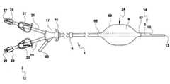
- FIG. 1illustrates a plan view of one embodiment of the dialysis catheter presented herein.
- FIG. 2Aillustrates an enlarged sectional view of the distal portion of the catheter shaft of FIG. 1 .
- FIG. 2Billustrates an enlarged sectional view of an alternative embodiment of the distal portion of the catheter shaft of FIG. 1 .
- FIG. 3Aillustrates an enlarged cross-sectional view of the distal portion of the catheter of FIG. 1 along line 3 A- 3 A.
- FIG. 3Billustrates a cross-sectional view of the distal portion of the catheter of FIG. 1 along line 3 B- 3 B.
- FIG. 4Aillustrates a plan view of an alternative embodiment of the catheter of FIG. 1 .
- FIG. 4Billustrates an enlarged cross-sectional view of the catheter of FIG. 4A along line 4 B- 4 B.
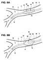
- FIG. 5Aillustrates a perspective view of the distal portion of the catheter of FIG. 1 in a deflated state positioned within a portion of a patient's bronchial vessel.
- FIG. 5Billustrates a perspective view of the distal portion of the catheter of FIG. 1 in an inflated state inserted into a portion of a patient's bronchial vessel.
- FIG. 6Aillustrates a perspective view of another embodiment of the catheter of FIG. 1 positioned within a portion of a patient's bronchial vessel.
- FIG. 6Billustrates a perspective view of another embodiment of the catheter of FIG. 1 positioned within a portion of a patient's bronchial vessel.
- FIG. 7Aillustrates an enlarged cross-sectional view of the catheter of FIG. 6A along line 7 A- 7 A.
- FIG. 7Billustrates an enlarged cross-sectional view of the catheter of FIG. 6A along line 7 B- 7 B.
- FIG. 8Aillustrates a perspective view of another embodiment of the distal portion of the catheter of FIG. 1 in a deflated state positioned within a portion of a patient's bronchial vessel.
- FIG. 8Billustrates a perspective view of the distal portion of the catheter of FIG. 1 in an inflated state positioned within a portion of a patient's bronchial vessel.
- FIG. 9illustrates a cutaway view of a human lung with the distal portion of the catheter of FIG. 1 inserted into a portion of a patient's bronchial vessel.
- FIG. 10illustrates a partial cutaway view of a human lung with the distal portion of the catheter of FIG. 1 inserted into a portion of a patient's bronchial vessel.
- FIG. 11Aillustrates a partial cutaway view of the distal portion of the catheter of FIG. 1 being inserted into a portion of a patient's bronchial vessel.
- FIG. 11Billustrates an enlarged view of a portion of the catheter shaft being inserted into a portion of a patient's bronchial vessel.
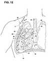
- FIG. 12illustrates a cutaway view of the distal portion of the catheter of FIG. 1 being inserted into a portion of a patient's bronchial vessel.
- FIG. 13illustrates a plan view of an additional embodiment of the catheter of the present invention.
- FIG. 14Aillustrates a cross-sectional view of the catheter of FIG. 13 along line 13 A- 13 A.
- FIG. 14Billustrates a longitudinal sectional view of a portion of the catheter shaft of FIG. 13 along line 13 B- 13 B.
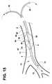
- FIG. 15illustrates a perspective view of the distal portion of the catheter of FIG. 13 inserted into a portion of a patient's bronchial vessel.
- FIG. 16illustrates a cutaway view of the distal portion of the catheter of FIG. 13 being inserted into a portion of the patient's bronchial vessel and a proximal portion of the catheter tubing being advanced toward a patient's diaphragm.
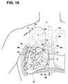
- FIG. 17illustrates an elevational schematic view of a distal portion of the catheter of FIG. 13 being inserted into a portion of a patient's bronchial vessel and a portion of the proximal portion of the catheter tubing being inserted into a patient's bladder.
- Rangescan be expressed herein as from “about” to one particular value, and/or to “about” another particular value. When such a range is expressed, another embodiment includes from the one particular value and/or to the other particular value. Similarly, when values are expressed as approximations, by use of the antecedent “about,” it will be understood that the particular value forms another embodiment. It will be further understood that the endpoints of each of the ranges are significant both in relation to the other endpoint, and independently of the other endpoint. As used herein, the words “proximal” and “distal” refer to directions away from and closer to, respectively, the insertion tip of the catheter in the catheter assembly. The terminology includes the words above specifically mentioned, derivatives thereof, and words of similar import.
- Form from and “formed of”denote open claim language. As such, it is intended that a member “formed from” or “formed of” a list of recited components and/or materials be a member comprising at least these recited components and/or materials, and can further include other non-recited components and/or materials.
- Polymeror “polymeric” refers to a natural, recombinant, synthetic, or semisynthetic molecule having in at least one main chain, branch, or ring structure having two or more repeating monomer units. Polymers broadly include dimers, trimers, tetramers, oligomers, higher molecular weight polymers, adducts, homopolymers, random copolymers, pseudocopolymers, statistical copolymers, alternating copolymers, periodic copolymers, bipolymers, terpolymers, quaterpolymers, other forms of copolymers, substituted derivatives thereof, and mixtures thereof, and narrowly refer to molecules having one or more repeating monomer units.
- Polymerscan be linear, branched, block, graft, monodisperse, polydisperse, regular, irregular, tactic, isotactic, syndiotactic, stereoregular, atactic, stereoblock, single-strand, double-strand, star, comb, dendritic, and/or ionomeric, can be ionic or non-ionic, can be neutral, positively charged, negatively charged, or zwitterionic, and can be used singly or in combination of two or more thereof.
- substantiallyAs used herein, “substantially”, “generally”, and other words of degree are relative modifiers intended to indicate permissible variation from the characteristic so modified. It is not intended to be limited to the absolute value or characteristic which it modifies, but rather possessing more of the physical or functional characteristic than its opposite, and preferably, approaching or approximating such a physical or functional characteristic. “Optional” or “optionally” means that the subsequently described element, event or circumstance can or cannot occur, and that the description includes instances where said element, event or circumstance occurs and instances where it does not.
- an exemplary cathetersuch as a dialysis catheter, and a method of treatment using the dialysis catheter in a human lung.
- FIGS. 1 through 3Billustrate one exemplary embodiment of a multilumen vascular access catheter, such as a dialysis catheter.
- the catheter assembly 1has a proximal end 12 and a distal end 14 . At least a portion of the proximal end 12 of the catheter assembly 1 can be configured to be positioned outside of a human body. At least a portion of the distal end 14 of the catheter assembly 1 can be configured to be inserted into at least a portion of an anatomical bodily opening of a human body, such as, but not limited to, a target location in a human lung.
- the target location in a human lungcan comprise a bronchial vessel.
- Bronchial vesselis defined herein to mean a bronchus or a bronchi of a human lung, including a transplanted lung or artificial lung. Thus, the terms “bronchial vessel” and “bronchi” are used herein interchangeably.
- the catheter assembly 1can comprise an elongate cylindrical flexible unitary body or catheter shaft 3 that has a proximal end, a distal end, and extends about a longitudinal axis that is positioned within a single plane, and at least one lumen.
- the catheter shaft 3can be about 9 Fr to about 19 Fr, or about 3 mm to about 6.33 mm in outer diameter and about 2 mm to about 5 mm in inner diameter.
- the outer diameter of the catheter shaft 3can be smaller than the inner diameter of a human bronchial vessel, such that at least a portion of the catheter shaft 3 is configured to be inserted into at least a portion of the lumen of a bronchial vessel.
- the catheter shaft 3can have a uniform diameter.
- the catheter shaft 3can have a wider diameter at the proximal end of the shaft 3 and a narrower diameter at the distal end of the shaft 3 to compensate for changes in anatomy during insertion.
- the catheter shaft 3can have a length of about 30 cm to about 78 cm. More particularly, the catheter shaft 3 can have a length of from about 30 cm to about 60 cm. In one exemplary aspect, the catheter shaft 3 can have a length of about 50 cm.
- At least a portion of the catheter shaft 3can be flexible, yet semi-rigid, and biasable and can be configured to conform to or align with the shape of an anatomical bodily opening, such as, but not limited to, a trachea, bronchus, bronchi, or any other desired bodily cavity in order to navigate the tortuous pathway between a trachea and a target location of a human lung.
- the distal portion 14 of the catheter shaft 3can be configured to be more flexible compared to the proximal portion 12 of the catheter shaft 3 to allow the distal portion 14 of the catheter to be more easily navigated into to a lumen of a bronchial vessel.
- At least a portion of the catheter shaft 3can be pre-curved (not shown) or it can be straight, as illustrated.
- the distal portion 14 of the catheter shaft 3can have a pre-curved, biased, or asymmetric shape with respect to the longitudinal axis of the catheter shaft 3 .
- This pre-curved or asymmetric shapecan facilitate better steering of the distal portion 14 past the carina 20 of the lungs, described herein, where the catheter can frequently get stuck.
- a curved tip catheteris advantageous because it can be easy to selectively insert the tip into the bronchus.
- This pre-curved shapecan also help the distal portion 14 be better aligned with and positioned within a bronchial vessel.
- the elongate catheter shaft 3 of the catheter assembly 1can be comprised of any suitable biocompatible plastic or elastomeric material, such as, but not limited to, polyurethane and polyethylene, or soft silicone elastomers.
- the catheter shaft 3can be composed of a Carbothane® material.
- At least a portion of the outer surface of the catheter shaft 3can be coated with one or more of the following: coagulation enhancing agents to stop bleeding, mucolytic agents to reduce or eliminate mucus production, anti-inflammatory agents, anti-proliferative agents, analgesics, antibiotic coatings, antimicrobial coatings, antifungal coatings, hydrophilic coatings, other lubricious coatings, regenerative agents for parenchymal regeneration, or any combination thereof.
- the catheter shaft 3can have a plurality of side ports defined therein at least a portion of an outer surface of the catheter shaft 3 at the distal end 14 of the catheter shaft 3 to allow for additional fluid flow.
- at least a portion of the catheter shaft 3can have at least one radiopaque indicia that can be incorporated anywhere along at least a portion of the catheter shaft 3 .
- the radiopaque indiciacan be placed along the catheter shaft 3 to aid a practitioner in indicating the depth of insertion of the catheter shaft 3 into a target location within a human lung.
- the radiopaque indiciacan provide information pertaining to the position or the orientation of the catheter or detection within the body by any suitable imaging technique.
- the radiopaque materialcan include, but is not limited to, barium sulfate, bismuth subcarbonate, zirconium dioxide, cadmium, tungsten, gold, tantalum, bismuth, platinum, iridium, and rhodium.
- a bifurcate or hub 17surrounds at least a portion of the outer surface of the proximal portion 12 of the catheter shaft 3 .
- the catheter assembly 1can have at least a first extension tube 19 and a second extension tube 21 and at least a first extension tube clamp 33 and a second extension tube clamp 31 .
- the clamps 33 , 31can be releasably attached to at least a portion of each extension tube 19 , 21 for selectively opening and closing the tubes 5 , 7 ( FIG. 2A ).
- at least one of the catheter extension tubes 19 , 21can have at least one pre-curved portion (not shown).
- the at least one pre-curved portioncan enable the extension legs to extend downward against a patient's body once the distal portion of the catheter assembly 1 has been placed into at least a portion of an anatomical bodily opening of a patient. This design can be beneficial because it can provide greater comfort for the patient.
- the hub 17also has an inflation port 63 having a proximal end and a distal end that can be used for injection of fluids or air into at least one of the catheter lumens.
- the catheter assembly 1 described hereinhas at least a first catheter hub connector or luer connector 23 and a second catheter hub connector or luer connector 25 for joining to an infusion pump or other injection or aspiration device in order to provide intravascular access to the patient.
- the distal end 14 of the catheterterminates in two distal tips or apertures 13 , 15 .
- the distal tips 13 , 15 of the catheter assembly 1can be atraumatic.
- the tips 13 , 15can be made of a soft material, such as silicone, urethane, and the like, that facilitates movement of the tips 13 , 15 .
- the tips 13 , 15can be rounded, tapered, or cone-shaped instead of blunt or square to facilitate steering of the catheter through the trachea and bronchial vessels.
- the catheter shaft 3can comprise at least one additional aperture that can be defined in the side wall of the catheter shaft 3 . More particularly, the catheter shaft 3 can comprise a plurality of apertures defined in the side wall of the catheter such that the apertures are in fluid communication between at least one lumen of the catheter shaft 3 and the exterior of the catheter shaft 3 . The apertures can be positioned within the catheter side wall at the distal portion 14 of the shaft 3 .
- Cuff 6which facilitates anchoring for tunneled catheters, can optionally be attached to at least a portion of the outer surface of the unitary catheter shaft 3 .
- Cuff 6can be useful for allowing subcutaneous tissue to grow into the cuff 6 and to help secure the catheter once it is implanted in a patient's body.
- Cuff 6can be composed of polyester or Dacron® polyester.
- the catheter assembly 1can also have a suture wing 16 , which can circumferentially surround the outer surface of the catheter shaft 3 .
- shaft 3can be comprised of at least one tube. More particularly, the catheter shaft 3 can be comprised of at least a first tube 5 and a second tube 7 , each having at least one lumen that extends substantially about the entire length or longitudinal axis of the shaft 3 .
- the tubes 5 , 7can be joined together for at least a portion of their length along an interface 45 .
- the catheter shaft 3 described hereincan have a staggered or stepped tip distal tip configuration ( FIG. 2A ) or a split tip distal tip catheter configuration ( FIG. 2B ), as well as other types of non-split tip distal tip catheter configurations.
- tubes 5 , 7can comprise at least one lumen. More particularly, tubes 5 and 7 can comprise an aspiration lumen 39 and an infusion lumen 36 , respectively.
- Lumen 39can be configured to withdraw fluid through lumen 39 under negative pressure.
- Lumen 36can be configured to infuse or return fluid to a patient under positive pressure, as described herein.
- At least one of the lumens 36 , 39can extend substantially longitudinally and independently parallel about the length or longitudinal axis of the shaft 3 from a proximal end 12 to a distal end 14 of the catheter shaft 3 . At least one of the lumens can extend substantially along the entire length of the catheter shaft 3 .
- lumen 36can be positioned on one side of the longitudinal axis, and lumen 39 can be positioned on a second side of the longitudinal axis.
- catheter lumen 36can be longer than catheter lumen 39 , or, alternatively, lumen 39 can be longer than lumen 36 .
- the first catheter lumencan be configured to extend deeper into an anatomical bodily opening, such as a bronchial vessel, compared to the second catheter lumen.
- Lumens 39 , 36are in fluid communication with first and second extension tubes 19 , 21 , and distal tips 15 , 13 , respectively. This enables the infusion or aspiration of fluids to and from the lung of a patient.
- Either of these lumens 36 , 39can be capable of selectively receiving a guide wire, which can be used during insertion of the catheter to a location in a bronchial vessel.
- Each lumenmay be of various sizes and shapes.
- the catheter shaft 3can have a plurality of lumens, such as, but not limited to, two, three or more lumens, if desired.
- aspiration tube 5 of the catheter shaft 3can have an inner surface 40
- infusion tube 7can have an inner surface 41
- Arterial tube 5has inner lumen surface 40 and an outer surface, which is also the outer surface of the catheter shaft 3
- venous tube 7has a venous lumen 36 with an inner lumen surface 41 .
- the portion of the catheter tube 5 that is defined between the outer surface of the catheter shaft 3 and the inner lumen surface 40defines the tube 5 sidewall.
- the portion of the catheter tube 7 that is defined between the outer surface of the catheter shaft 3 and the inner lumen surface 41defines the tube 7 sidewall.
- Each catheter tubecan have a substantially equal wall thickness.
- each catheter tube 5 , 7can have a variable wall thickness.
- the catheter shaft 3can have a unitary septum 77 , illustrated in FIG. 3A .
- each catheter lumen of the dual lumen configurationcan have a variable shape, such as, but not limited to, D-shaped, oval ( FIG. 38 ), circular, elliptical, or any other suitable lumen configuration, diameter, material, thickness, or length, in any combination thereof.
- the catheter tubes 5 , 7are preferably designed to maximize the cross-sectional diameter of the lumens 36 , 39 to achieve increased flow rates during aspiration and infusion.
- the cross-sectional area of the D-shaped lumens 36 , 39can be substantially equal.
- lumens 36 , 39can have different cross-sectional areas.
- lumen 36can have a first cross-sectional area
- lumen 39can have a second cross-sectional area.
- lumen 36can have a larger cross-sectional area than lumen 39 along at least a portion of its longitudinal length.
- lumen 39can have a larger cross sectional area than lumen 36 along at least a portion of its longitudinal length.
- the catheter assemblycan be identical to the catheter assembly as described above, except that the catheter only has one lumen and one extension tube.
- infusion of fluid into the cathetercan be established from the proximal end 12 to the distal end 14 and into a patient's lung, and outflow or aspiration from the patient's lung can be selectively established from the distal end 14 of the catheter to the proximal end 12 .
- the single central lumen 36terminates at the proximal end 12 of the catheter and is fluidly joined to a single extension tube 19 , where the catheter can be connected to an infusion pump. Fluid infusion can be carried out under positive pressure, and fluid aspiration can be carried out under negative pressure.
- “Positive” pressuremeans that the static pressure in the lumen 36 near the distal end 14 can exceed the static pressure external to the distal end 14 . “Negative” pressure refers to conditions where the static pressure external to the distal end 14 exceeds the static pressure in the lumen 36 near the distal end 14 .
- At least a portion of the outer surface of the catheter shaft 3can be surrounded by at least one means for substantially sealing an anatomical bodily opening, such as, but not limited to, a bronchial vessel.
- the means for sealing the bronchial vesselcan be, but is not limited to an inflatable or expandable member, such as a balloon 24 or similar structure.
- a balloon 24is described herein as being used as a sealing means, one of ordinary skill in the art will recognize that other means for sealing can be used.
- the balloon 24can be movable between a collapsed insertion state and an expanded sealing state.
- the balloon 24can have an outer surface 99 and an inner surface 18 .
- the balloon 24can be disposed at least partially coaxially in surrounding relation around at least a portion of the outer surface of the catheter shaft 3 such that an annular balloon interior cavity 9 is defined between the inner wall 18 of the balloon and the outer surface of the catheter shaft 3 .
- At least a portion of the catheter shaft 3extends through the cavity 9 of the balloon 24 and carries the balloon 24 .
- the balloon 24can have a cylindrical section with a maximum diameter that tapers down to reduced diameters at the proximal end 65 and the distal end 67 .
- At least a portion of the inner surface 18 of the proximal end 65 and the inner surface 18 of the distal end 67 of the balloon 24can be operably connected to at least a portion of the outer surface of the distal portion 14 of the catheter shaft 3 by bonding, welding, clamping, fusing, or any suitable method known in the art.
- the distal end 67 of the balloon 24terminates proximally of both of the distal apertures 13 , 15 .
- an air tight sealis formed.
- the distal end 67 of the balloon 24can terminate between about 2 cm and about 4 cm proximally from the distal end of the most proximal edge of the catheter tips 13 , 15 .
- the balloon 24can extend longitudinally along the outer surface of the catheter shaft and can be between about 10 mm and about 40 mm in length.
- the inner diameter of the proximal and distal ends of the balloon 24 that surround the outer surface of the catheter shaft 3can be between about 2 mm and about 10 mm in diameter, to form a snug fit around the outer surface of the catheter shaft 3 .
- the maximum inflated diameter of the balloon 24can be between about 3 mm and about 22 mm in diameter, depending on the size of the patient or the lung cavity treated. More particularly, the maximum diameter of the balloon 24 can be between about 14 mm and about 22 mm. More particularly, the outer diameter of the balloon 24 can be between about 3 mm and about 12 mm.
- the balloon 24can have a maximum expanded diameter of between about 12 mm and about 16 mm.
- the maximum diameter of the balloon 24 in the expanded statecan be substantially equal to or greater than the inner diameter of a bronchial vessel, such as a bronchi, in order to help form an interference fit between the outer surface 99 of the balloon 24 and the inner wall 11 of the bronchial vessel 49 .
- the outer diameter of the balloon 24can have a diameter, when inflated, that is between about 0.5 mm to about 1.00 mm more than the outer diameter of the balloon 24 .
- the diameter of the balloon 24can be varied in response to the amount of pressurized air that is infused into the cavity 9 of the balloon 24 .
- the wall thickness of the balloon 24can be optimized to ensure a substantially complete seal between the inner wall of the bronchial vessel and the outer wall of the balloon. At least a portion of the balloon 24 can be configured to conform to the geometry of at least one of the lumen of the trachea and the bronchial vessel where the catheter is placed. In one exemplary embodiment, at least a portion of the outer surface of the balloon 24 can be configured to conform to the lumen of at least one of the trachea and the bronchial vessels to substantially seal the lumen.
- the outer surface 99 of the balloon 24can be configured to substantially conform to the shape of at least one space between cartilaginous rings located in at least one of: the trachea and the bronchi, thereby forming a substantially complete seal between the outer surface 99 of the balloon 24 and the inner wall 11 of the bronchial vessel.
- the walls of the trachea and the bronchiinclude C-shaped cartilage rings separated by softer intervening tissue such as fibrous tissue, muscular fibers, mucous membrane, and glands.
- the tracheal cartilaginous ringsvary from fifteen to twenty in number and may be spaced about 1-4 mm apart along the tracheal wall. The rings help stiffen the tracheal wall and help keep the tracheal airway open.
- the balloon 24can be a high strength, high volume, low pressure, balloon with a thin, highly flexible relatively inelastic wall that is readily inflatable under pressure and readily collapsible under vacuum, such that the balloon can stretch a relatively small amount under pressures of up to about 15 atmospheres or more.
- balloon 24can have an average burst pressure of between about 2 atmospheres and about 6 atmosphere, and more particularly, between about 4 atmospheres and 6 atmospheres.
- the ballooncan be between about 0.0005 inches and 0.020 inches in thickness.
- the balloon 24can be made of a lightweight, flexible material, such as, but not limited to, one or more layers of any suitable expandable or distensible material such as nitrile, butyl rubber, viton, nylon, neoprene butanes, thermoplastic polymers, aliphatic polyurethanes, aromatic polyurethanes, thermoplastic polyurethane elastomers, low-density polyethylene, polyethylene terephthalate, polyethylene terephthalate glycol, silicone, natural rubber, synthetic rubber, latex, or any other suitable biocompatible elastomers, or any combination thereof.
- any suitable expandable or distensible materialsuch as nitrile, butyl rubber, viton, nylon, neoprene butanes, thermoplastic polymers, aliphatic polyurethanes, aromatic polyurethanes, thermoplastic polyurethane elastomers, low-density polyethylene, polyethylene terephthalate, polyethylene terephthalate glycol
- the balloon 24can also be made of a combination of materials with a combination of distensibilities, such as, but not limited to those described in U.S. Pat. No. 6,004,339, incorporated herein by reference.
- the balloon 24can be distensible and inflatable or deflatable in response to air, fluid, or gases that pass through lumen 43 .
- Fluidis defined herein to mean either fluids or gases, including bodily fluids.
- the balloon 24can have at least one radiopaque marker placed on at least a portion of the balloon 24 that can aid in visualization of the balloon during insertion and use.
- the outer surface 99 of the balloon 24can be coated with a water soluble lubricant.
- the balloon 24can be any type of suitable balloon known in the art that is configured to be inflated during use. In one exemplary aspect, although only one balloon 24 is illustrated, in one aspect, a plurality of balloons 24 can be positioned therein at the distal end 14 of the catheter shaft 3 .
- the interior cavity 9 of the annular balloon 24can be fluidly connected with at least one lumen of the catheter shaft 3 .
- the balloon 24can be in fluid communication with inflation lumen 43 .
- the inflation lumen 43has a proximal end and a distal end that can be connected to an inflation source.
- the proximal end of the inflation lumen 43can be configured to be operatively and fluidly connected to the distal end of inflation port 63 that is positioned at the proximal end of the catheter.
- Inflation lumen 43has an inner wall 47 ( FIG. 3A ).
- the inflation lumen 43is configured to receive fluids, gas, or air.
- the inflation lumen 43can be positioned at other various locations along the catheter shaft 3 , provided that the opening 69 , described below, is positioned within the balloon 24 .
- the inflation lumen 43can be positioned within the wall of the catheter shaft 3 or outside of and adjacent to the outer wall of the catheter shaft 3 . At least a portion of the inflation lumen 43 is can be in fluid or gaseous communication with the interior cavity 9 of the balloon 24 . If the inflation lumen 43 is positioned within the wall of the catheter shaft 3 , this can enable the cross-sectional lumen configuration of lumen 36 to remain substantially equal to lumen 39 , thereby maintaining the cross-sectional area of the catheter shaft.
- Lumen 43extends from the distal end of the inflation port 63 along a portion of the longitudinal axis of the shaft 3 substantially parallel with infusion and aspiration lumens 36 , 39 to at least one opening 69 .
- Opening 69is defined in the outer surface of the catheter shaft 3 and is positioned proximally of the distal end 67 of the balloon 24 and distally of the proximal end 65 of the balloon 24 and distally of the distal tips 13 , 15 of the catheter shaft 3 . This enables at least a portion of the inflation lumen 43 to be in fluid communication with at least a portion of the interior cavity 9 of the balloon 24 through opening 69 .
- the proximal end of the inflation port 63can be operably connected to and in fluid communication with a means for inflating (not shown) the balloon 24 .
- the means for inflating the balloon 24can be, but is not limited to, a vacuum, a lockable syringe, a plunger, an infusion source, or the like.
- the means for inflatingcan be used to inflate the balloon 24 .
- Any suitable inflation mediumcan be used to inflate the balloon 24 , such as, but not limited to, liquid, air, saline, or any other gas that is suitable for use in patients. When an inflation medium is infused into the balloon 24 , the balloon expands radially outwardly.
- the dimensions of the inflation port 63 and the inflation lumen 43can be configured to permit the flow of fluids, gases, or air from the inflation port 63 through the inflation lumen 43 and the opening 69 into or from the interior cavity 9 of the balloon 24 during inflation and deflation of the balloon 24 .
- the inflation lumen 43 and the opening 69can have a diameter of between about 0.2 mm and about 0.4 mm and a length from the proximal end of the hub to opening 69 of between about 5 mm and about 10 mm.
- the catheter assembly 1can optionally include a separate means for measuring or indicating the air pressure level or a change in air pressure within the balloon cavity 9 at the distal end of the catheter.
- the means for measuring air pressurecan be, but is not limited to, a balloon, a pressure gauge, or a sensor.
- the means for measuring the air pressurecan be attached to the inflation lumen 43 at the proximal end of the catheter assembly 1 to assist the user in detecting the pressure that is in the balloon 24 .
- the balloon 24can be pre-formed in a substantially deflated state before use, between uses, or during passage of the balloon 24 through lumen 2 of a bronchial vessel 49 , as illustrated in FIG. 5A .
- a vacuumcan be used to remove air from the balloon cavity 9 .
- the balloon 24can be configured such that at least a portion of the inner surface 16 of the balloon 24 can lie close against the outer surface of the catheter shaft 3 .
- the balloon 24In its collapsed or deflated state, the balloon 24 can have a length of about 10 mm and a minimum transverse dimension or diameter of about 2 mm for insertion and passage through the bronchial vessels.
- the balloon 24In its deflated state, the balloon 24 can have a diameter that is substantially the same as the outside diameter of the catheter shaft 3 .
- the collapsed diameter of the balloon 24can be smaller than the inner diameter of the bronchial vessel 49 , such that the overall diameter of the catheter is suitable for insertion and passage through a lumen 2 of a bronchial vessel 49 without protruding and interfering with such insertion or engaging the inner wall 11 of the bronchial vessel 49 .
- the balloon 24In all of the embodiments described herein where the balloon 24 is compressed before insertion, the balloon 24 has a first diameter in the expanded or anchoring state and a second diameter in the deflated state. The first diameter is larger than the second diameter.
- the balloon 24can have a pre-formed expanded outer state that is substantially fixed before the distal portion of the catheter assembly is inserted into a bronchial vessel of a target lung region.
- the balloon 24In its original pre-formed expanded configuration, the balloon 24 can have an expanded state or configuration with a first expanded diameter, as described below.
- the balloon 24can be deflated and can have a second deflated diameter that is smaller than the first diameter. The balloon 24 can then be allowed to return to its first expanded diameter once the sealing means or balloon 24 is positioned within the bronchial vessel of the target lung region.
- the pre-formed expanded configuration of the balloon 24ensures that when the balloon 24 returns to its original form after collapse within the bronchial vessel of the target lung region, the pre-formed balloon 24 will assume a fully expanded state having an outer configuration that can fully expand within the lumen of a bronchial vessel of a target lung region.
- the balloon 24After the balloon is inserted into the bronchial vessel, it can be inflated using inflation lumen 43 .
- the balloon 24can have a circular or spherical outer circumference when viewed along a cross-section ( FIGS. 3A , 4 B). While balloon 24 is generally described herein as having a round, expanded cross-section with a generally uniform single transverse dimension, in other exemplary aspects, the balloon 24 can have an overall oval or elliptical outer shape.
- the balloon 24can have any shape having a transverse dimension that can be expanded to contact opposing portions of interior wall 11 of bronchi 49 . In one exemplary aspect, when inflated, the balloon 24 can have a maximum diameter of between about 14 mm and about 22 mm.
- the maximum outer diameter of the expanded ballooncan be substantially equal to or greater than the inner diameter of the lumen of bronchial vessel 49 .
- the outer surface 99 of the balloon 24can provide a smooth and gentle surface during inflation of the catheter assembly 1 , such that any trauma to the inner wall 11 of the anatomical bodily vessel is minimized.
- the outer surface 99 of the balloon 24can exert a sufficient outward radial force on the inner surface 11 of the bronchi 49 to maintain the balloon's position within a patient's bronchial vessel, to engage the inner wall 11 , and to help prevent migration of the balloon 24 and the catheter.
- the balloon 24has a sufficiently dimensioned outer surface area 99 that can provide maximum optimal contact with the inner bronchial wall 11 of the bronchial vessel 49 after it is inserted into the bronchial vessel, while minimizing potential trauma to the bronchial vessel 49 .
- the balloon 24When inflated, the balloon 24 can expand and contract in size to fit within and seal bronchial lumens 2 of various sizes, described herein.
- the sealprevents fluid from flowing between the interior wall 11 of the bronchi 49 and the outer surface 99 of the balloon 24 .
- the balloon 24also functions as an anchor and holds the distal portion of the catheter in place within a bronchial vessel 49 , thereby minimizing or eliminating any movement of the catheter assembly 1 while in use.
- the balloon 24can be deflated before it is removed from the patient's bronchial vessel 49 .
- the balloon 24can comprise a plurality of elevated radially extending circumferential ridges 81 , 38 , 53 , each separated by a trough 42 .
- the ridges and troughsform an integral part of the balloon 24 and define a uniform outer surface 99 and a variable diameter of the balloon 24 .
- the balloon 24When the balloon 24 is in the expanded or inflated position, the balloon 24 can be positioned within the lumen 2 of the bronchi 49 such that at least a portion of the outer surface 99 of the balloon along a first ridge 81 , a second ridge 38 , and a third ridge 53 contact inner wall 11 of the bronchi 49 .
- the outer surface 99 along each ridgecan circumferentially contact the inner wall 11 of the bronchi 49 such that the outer circumference of each of the sealing ridges 81 , 38 , 53 forms a substantially complete seal with the inner wall 11 of the bronchi 49 .
- the ridges and troughs of the balloon 24can be configured to allow each ridge to align with the intervening tissue spaces between each successive cartilaginous ring.
- Each successive ridgecan be spaced apart between about 1-4 mm to facilitate this alignment. This spacing may allow each ridge to conform more closely to the shape of the tracheal lumen 26 or the inner wall 11 of the bronchial lumen 2 , resulting in an improved seal. Alternatively, the ridges may be irregularly spaced apart along the axis of the catheter shaft 3 .
- each trough 42has a lower height and smaller outer diameter compared to the height and outer diameter of each of the sealing ridges 81 , 38 , and 53 .
- the trough 42 region of the balloon 24can form a minimal contact or no contact region with the inner wall 11 of the bronchial vessel. In this minimal contact region, the outer surface 99 of the balloon 24 is generally not in contact with the inner wall 11 of the bronchi 49 .
- the smaller the diameter of the trough 42the larger the gap between the outer surface 99 of the balloon 24 and the inner wall 11 of the bronchi 49 .
- the maximum diameter of each ridgecan be substantially equal.
- the sealing ridges 38 , 53 , and 81can be any suitable height, width, shape or dimension, provided that the outer surface of the balloon 24 along at least one ridge forms a substantially complete seal with the inner wall 11 of the bronchial vessel 49 .
- the balloon 24has a rounded or circular cross sectional configuration. Together, the series of ridges and troughs can form a curved, undulating, or sinusoidal series of shapes, as viewed from the side ( FIGS. 6A and 6B ).
- the outer surface 99 of each ridgecan be rounded and smooth, squared, pointed, or any other suitable shape, provided that the shape does not cause trauma to the inner wall 11 of the bronchial vessel 49 .
- First ridge 81is capable of withstanding a first pressure that can be exerted at any point of contact between at least a portion of the outer wall 99 of sealing ridge 81 and a portion of the inner wall 11 of the bronchial lumen 2 of the balloon 24 such that a substantially complete seal can be formed.
- Second ridge 38can be capable of withstanding a second pressure at any point of contact between at least a portion of the outer wall 99 of sealing ridge 28 and a portion of the inner wall 11 of the bronchial lumen 2 such that a substantially complete seal can be formed.
- the second pressurecan be substantially lower than the first pressure.
- Second ridge 38can be capable of maintaining a seal between at least a portion of the outer wall 99 of the balloon 24 and a portion of the inner wall 11 of the bronchial lumen 2 against the reduced pressure along ridge 38 such that a substantially complete seal can be formed.
- Third ridge 53is capable of withstanding a third pressure at the point where at least a portion of the outer surface 99 of the balloon 24 contacts a portion of inner wall 11 of the bronchial lumen 2 along ridge 53 such that a substantially complete seal can be formed.
- the third pressurecan be substantially lower than the second pressure.
- any number of suitable ridgescan be used to provide a substantially complete seal between at least a portion of the outer surface 99 of the balloon 24 with the inner wall 11 of the bronchi 49 . This seal can help to retain the balloon 24 and prevent the catheter from migrating within the bronchi 49 , as described above.
- balloon 24can comprise a tubular mesh 71 .
- the mesh design 71can surround at least a portion of the outer surface 99 of the balloon 24 .
- the mesh design 71can be embedded within at least a portion of the outer surface 99 of the balloon 24 .
- the mesh design 71can be free-floating about at least a portion of the outer surface 99 of the balloon 24 .
- the mesh 71 designcan be expandable and collapsible.
- the mesh 71 materialcan be made from a woven filament which can be connected to the outer surface 99 of the balloon 24 .
- the mesh 71 materialshould be sufficiently strong that the balloon 24 can be retained within the mesh pattern.
- the mesh 71 materialcan comprise a plurality of fibers or filaments.
- the fiberscan be inelastic, having minimal elasticity or stretch under stresses imposed upon the balloon 24 during use of the catheter.
- the fiberscan include, but are not limited to, polyurethane, lycra, carbon fibers, ceramic fibers, metal, stainless steel, plastic, or any combination thereof.
- the mesh design 71 of the balloon 24can be braided, woven, cross-helically wound, hexagonal or interlaced pattern, or any other suitable pattern.
- the mesh 71 configurationcan be configured to have varying radial and longitudinal pitches of weave patterns.
- the filamentscan have a rounded outer cross-sectional shape to provide a relatively smooth non-abrasive outer surface against the inner wall 11 of the balloon 24 .
- the filamentscan have varying diameters, depending on the shape and surface texture desired of the balloon 24 .
- the filamentscan be between about 0.2 mm and about 0.3 mm in thickness.
- the mesh 71 pattern of the balloon 24can contact and engage the inner wall 11 of the bronchi 49 , thereby allowing a secure interference fit between the outer surface 99 of the balloon 24 /mesh 71 and the inner wall 11 of the bronchial lumen 2 .
- the maximum diameter of the mesh 71 patterncan be equal to or greater than the inner diameter of the lumen 2 of the bronchi 49 in order to create a substantially complete seal of at least a portion of the outer surface 99 of the balloon 24 with the inner wall 11 of the bronchial lumen 2 .
- the mesh 71 patternmay have a predetermined limit of expansion such that the balloon 24 can be prevented from further radial or axial expansion, regardless of the amount of pressure that is infused into the balloon cavity 9 . This predetermined limit of expansion can be helpful for preventing rupture of the balloon 24 or other damage to the bronchial lumen 2 .
- the balloon illustrated in FIG. 6Bhas a mesh 71 and ridges, in another aspect, the mesh 71 can be used with any of the catheter assemblies disclosed herein.
- the mesh design 71can give the balloon 24 added strength and traction while implanted within the bronchi 49 .
- the mesh 71 patterncan also prevent the balloon 24 from migrating within the bronchi 49 , overinflating and rupturing, or damaging the bronchi 49 .
- the sealing means 24can comprise a plurality of resilient radially extending ribs 79 .
- the ribs 79can be spaced apart from each other to form an expandable and collapsible cage 30 structure.
- Each rib 79has a proximal end and a distal end. The proximal end of each rib 79 is secured to at least a portion of the inner surface 18 of the balloon 24 and the outer wall of the catheter shaft 3 at the proximal end 65 of the balloon 24 .
- the cage 30can be encapsulated within the balloon 24 such that at least a portion of each rib 79 is secured to at least a portion of the inner wall 18 of the balloon 24 .
- each rib 79can be selectively coupled to the inner wall 18 of the balloon 24 .
- the ribs 79 of the cage 30can be made of any suitable shape memory metal, such as, but not limited to, nitinol or nickel-titanium or other malleable materials.
- the balloon 24 and cage 30Before the balloon 24 with cage 30 is inserted into a bronchial vessel, the balloon 24 and cage 30 can be in a deflated state, as illustrated in FIG. 8A . After the balloon 24 and cage 30 are inserted into the patient's bronchi 49 , the balloon 24 can be expanded or inflated, as illustrated in FIG. 8B .
- the ribs 79 of the cage 30can be radially expandable around the outer circumference of the catheter shaft 3 within at least a portion of the balloon 24 .
- the cage 30can be pre-shaped to self-expand when it is placed into a portion of the bronchi 49 . In one example, the cage 30 can be collapsed when drawn within an insertion catheter or sheath.
- the cage 30can be expanded to press the outer wall 99 of the balloon 24 against the inner wall 11 of the bronchi 49 , thereby forming an engaging interference fit or seal with the inner wall 11 of the bronchi 49 .
- the cage 30 configurationcan help to exert a radial force or pressure against the inner wall 11 of the bronchi 49 that is sufficient to retain and anchor the balloon 24 in place. This helps to create a substantially complete seal between the outer wall 99 of the balloon 24 and the inner wall 11 of the bronchial lumen 2 and prevents the catheter from being dislodged or inadvertently pulled out of the bronchi 49 .
- FIGS. 9 through 12The method of using any of the catheter assemblies illustrated in FIGS. 1 through 8B to perform dialysis treatment in a target lung region is described with reference to FIGS. 9 through 12 .
- the balloon 24 of the catheter assembly 1can be selectively deflated, as illustrated in FIG. 5A , prior to insertion by drawing a vacuum on it (not shown).
- FIG. 9one method of insertion and use of the catheter assembly 1 is illustrated.
- This methodinvolves identifying a target lung region in a human lung into which the catheter assembly 1 described herein can be inserted.
- the term “lung region”refers to a defined portion of a lung.
- the target lung regioncan include an anatomical bodily opening, such as, but not limited to, a bronchi 49 , which is surrounded by lung parenchymal tissue 55 , as schematically illustrated in FIG. 9 .
- the lung parenchyma 55acts primarily as a filter.
- the methodcan further involve determining the diameter of a bronchi 49 of the target lung region, and providing an appropriately sized catheter assembly 1 described herein, for insertion into at least a portion of the bronchi 49 .
- the diameter of the bronchican be estimated, based on the patient's size, age, and gender. Alternatively, other various methods known in the art for determining the inner diameter of the bronchi 49 can be used. For example, the diameter can be measured using a high resolution CT scan. A loop or measuring device, such as a marked linear probe can also be used. Although bronchial diameter can vary widely among individuals, the average diameter of the bronchi for males can be about 15 mm, or 0.68 of the average tracheal width of 22 mm, and the average diameter of the bronchi for females can be about 12 mm, or 0.68 of the average tracheal width of 17 mm. All dimensions of the catheter assembly 1 disclosed herein are exemplary in nature, and can vary, depending on patient anatomy.
- a percutaneous incision 22can be made in the skin of a patient's chest area below the clavicle.
- a needleis inserted into the incision 22 in the patient's skin and is advanced through the tissue underneath the skin. The needle is further advanced into the thoracic cavity and further toward the trachea 83 .
- the trachea 83can then be palpated and stabilized with the thumb and forefinger of a practitioner's hand, and the needle can be slowly advanced in a horizontal direction towards the trachea 83 with a practitioner's remaining hand while directing the needle straight towards the midline of the trachea 83 , in order to enable penetration of the lumen 26 of the trachea 83 .
- the needlecontacts the wall of the trachea 83 , the needle can be advanced a short distance up or down in order to find and penetrate a ligament between two cartilaginous tracheal rings.
- a distinct popcan usually be felt.
- the needleAfter penetration of the trachea 83 , the needle can be carefully held in position within the lumen 26 of the trachea 83 , to prevent it from prematurely backing out of the airway. If the needle is advanced too far within the lumen 26 of the trachea 83 , the dorsal wall of the trachea 83 can prevent the catheter from passing through the needle.
- the needlecan be slowly turned from a horizontal position to a 45 degree angle, pointing bevel-down towards the carina 20 , or cough center, positioned at the junction of the left and right bronchi.
- the tracheahas a series of cartilaginous semi-rigid rings, described above, that help to maintain the tracheal airway. Between each of the cartilaginous rings is a thin, soft tissue. As schematically illustrated in FIGS.
- the trachea 83divides into two branches, which become the bronchi of the lungs, a right primary bronchus 37 and a left primary bronchus, that each provide direct air flow to the right and left lungs, respectively.
- the bronchiare connected to the lungs.
- the lungsare large, paired, spongy, elastic organs, which are positioned in the thoracic cavity. The lungs are in contact with the walls of the thoracic cavity.
- the right lungcomprises three lobes, and the left lung comprises two lobes.
- Each of the left and right lungsis covered with a pleural membrane or sac.
- the pleural spaceis the space surrounding the lungs.
- the thoracic cavityis normally a closed system, and air cannot enter or leave the lungs except through the trachea. Healthy lungs have a large surface area for gas/air exchange.
- Each of the primary bronchi 37 , 85divides into bronchial vessels 49 , 28 , which are defined by a lumen through which fluids and air can flow to and from the lung.
- the lobar bronchifeed fluid directly to a respective lung lobe, and each lobar bronchi divides into bronchial vessels that are comprised of segmental bronchi, which provide air flow to the bronchopulmonary segments.
- the bronchibranch into bronchioles, and the bronchioles lead to alveolar sacs which include multiple alveoli separated by alveolar walls for the exchange of oxygen and carbon dioxide.
- the bronchial arteriessupply blood to the bronchi and connective tissue of the lungs. They travel with and branch with the bronchi, ending about at the level of the respiratory bronchioles. They anastomose with the branches of the pulmonary arteries, and together, they supply the visceral pleura of the lung in the process.
- a guide wireis inserted into the trachea 83 through the inserted needle.
- the guide wirecan be about 0.035 inches in overall diameter, although other lengths and diameters are possible.
- the needleis then withdrawn, with the guide wire being left in place.
- a dilator/sheath assemblycan then be placed over the guide wire and advanced to a position inside the trachea 83 .
- the dilatoris removed, and the distal portion 14 of the catheter assembly 1 is inserted into the sheath, back loaded over the proximal end of the guide wire, and advanced via tunneling beneath the skin until the cuff 6 is positioned just beneath the skin.
- the guide wireis used to control the path of the catheter shaft 3 , which tracks over the guide wire, and ensures that the catheter shaft 3 properly negotiates the path to the target lung region.
- the distal portion 14 of the catheter assembly 1is introduced into the trachea 83 via the introducer sheath and over the guide wire and advanced through the trachea 83 into the right bronchus 37 and further into the right bronchi 49 , being careful to avoid the carina 20 .
- the cathetercan conform to the shape of the trachea until the distal portion 14 of the catheter assembly 1 is located at the target lung location of the bronchi 49 , as illustrated in FIG. 9 . Passage of the catheter shaft 3 through tortuous bronchial anatomy can be further facilitated by using a steerable distal end portion 14 of the catheter shaft 3 that can be controlled remotely.
- the catheter assembly 1can be positioned such that the distal tips 13 , 15 of the catheter are located at the proper position within the bronchi 49 , as confirmed under ultrasound or fluoroscopy. Markers positioned along the catheter shaft 3 can be used to indicate the desired depth of the catheter shaft 3 within the right bronchi 49 .
- the proximal portion 65 of the inflated balloon 24can be positioned approximately 10 mm past the beginning of the right bronchus 37 into the right bronchi 49 .
- the guide wirecan be configured to extend only a minimally short distance from the distal portion of the catheter shaft 3 to minimize the chance of puncturing the lungs.
- the distal portion 14 of the catheter assembly 1is shown inserted into the right bronchi 49 , alternatively, the distal portion 14 of the catheter can be inserted into the left bronchi.
- it is more difficult to insert the catheter into the left bronchial passage compared to the right bronchial passagebecause the left bronchial passage is slightly smaller and branches at a slightly greater angle from the main trachea 83 compared to the right bronchial vessel.
- the right bronchi 49is better suited for catheter insertion because it is wider, more vertical, 5 cm shorter than the left bronchi, and is positioned at a 20-30 degree angle compared to the left bronchi, which is narrower, longer, and more angular, having a 40-60 degree angle, compared to the right bronchi.
- the catheter assembly 1can be laparoscopically inserted into a target lung region.
- This techniqueinvolves the use of a laparoscope that can be manually advanced in parallel with the catheter shaft 3 .
- the use of the catheter assembly 1 with a laparoscopeallows a clinician to gain visual and functional access to the interior of a patient's lungs.
- visualization of the progress of the distal tips 13 , 15 of the catheter shaft 3can be provided by, but is not limited to, a bronchoscope, x-ray, ultrasonic, radiographic, computed tomography (CT), or other video-assisted techniques or visualization systems to provide supplemental visualization during the insertion procedure.
- CTcomputed tomography
- Video-assisted techniquescan involve using a small video camera that is introduced into the patient's chest via a scope.
- a practitionercan view the instruments that are being used along with the anatomy into which the catheter is being inserted.
- the camera and instrumentscan be inserted through separate holes in the chest wall, also known as “ports”. Fluoroscopy can be used to visualize and ensure that the guide wire is not dislodged while the catheter shaft 3 is advanced over the guide wire.
- the guide wire and the sheathcan then be removed, leaving at least a portion of the distal portion 14 of the catheter assembly within the bronchial vessel 49 .
- At least a portion of the distal portion 14 of the catheter assembly 1is confirmed as being located at the proper position within the lumen 2 of the right bronchi 49 , at least a portion of the bronchi 49 of the target lung region can be bronchially isolated. This is accomplished by inflating the balloon 24 of the catheter assembly 1 within a portion of the bronchi 49 to form a substantially complete seal between a portion of the outer wall 99 of the balloon 24 and a portion of the inner wall 11 of the bronchial lumen 2 .
- fluid, gas, or aircan be infused into inflation port 63 , through lumen 43 , and into the balloon 24 through opening 69 using a syringe or vacuum device that can be attached to the inflation lumen port 63 at the proximal end of the catheter assembly 1 , as described above.
- a syringe or vacuum devicethat can be attached to the inflation lumen port 63 at the proximal end of the catheter assembly 1 , as described above.
- an infusion of approximately 0.5 to 10 mL of aircan be sufficient to inflate the balloon 24 such that it can cause occlusion across the diameter of an anatomical bodily opening, such as, but not limited to, the right bronchi 49 .
- the diameter of the balloon 24can expand so that at least a portion of the outer surface 99 of the balloon 24 can engage at least a portion of the inner wall 11 of the bronchi 49 , thereby forming a substantially complete seal of the lumen 2 of the bronchi 49 .
- Thisis important because the bronchial lumen 2 can become constricted or otherwise change shape during inhalation, exhalation, or coughing. If the balloon 24 is not secured properly, when a patient coughs, pressure can build up behind the catheter, which can lead to migration or expulsion of the balloon catheter from the bronchial lumen 2 .
- the bronchial lumensexpand when air is inhaled, which can cause the catheter to migrate in the distal direction, and can result in the device being pushed further into the lung. This can lead to a less secure retention of the device in the bronchial lumen 2 .
- the seal created by the inflated balloon 24helps to isolate or seal off at least a portion of the lung to create a treatment chamber that is located distally of the point where a portion of the outer surface 99 of the balloon 24 contacts a portion of the inner wall 11 of the bronchial lumen 2 for dialysis treatment.
- the position of the balloon 24can be inspected under fluoroscopy and adjusted, if necessary, so that the inflated balloon fills the bronchial lumen 2 without herniation into the lumen 26 of the trachea 83 .
- the balloon inflation volumecan also be noted, and the inflation volume can be between about 5 ccs and about 10 ccs. The inflation volume will depend on the size of the catheter, the size of the bronchial vessel in which the catheter assembly is to be placed, and the like. If the balloon 24 is mis-positioned, the balloon 24 can be deflated, if necessary and then reinflated when appropriate.
- the balloon 24should fill a majority of the bronchi 49 , such that at least a portion of the lumen 2 can be substantially occluded.
- the cathetercan be re-positioned by inflating the balloon 24 such that it can be used to position the distal tip of the catheter in the proper location.
- the methods of insertion described hereinare advantageous because the catheter assembly 1 does not have to be inserted via the mouth or nose, thereby leaving the patient free to breathe in an unobstructed manner.
- dialysatecan be infused into the patient from an infusion pump (not shown). Fluid can be withdrawn from the patient's venous system and transported through aspiration lumen 39 , illustrated in FIG. 2A , of tube 5 at opening 15 , through extension tube 21 and out opening 27 . Aspiration of the blood through aperture 15 of tube 5 can be accomplished by drawing a vacuum or negative pressure, causing the blood to be drawn through the catheter. Dialysate can then be infused into to the patient's lung through opening 27 of luer connector 25 on extension tube 19 which is connected to the infusion pump, into infusion lumen 36 of infusion or venous tube 7 with infusion lumen 36 ( FIG.
- lumens 39 and 36have been designated as aspiration and infusion lumens, respectively, the functions of these lumens can be reversed, if desired.
- the dialysis treatment processcan be repeated several times using the same catheter.
- a predetermined bolus of dialysate fluidcan be infused into the patient's lung through lumen 36 at a predetermined temperature, volume, and infusion rate.
- a new bolus of dialysatecan be infused into the lung.
- about 150 mls of dialysate solutioncan be infused into a patient's lungs during treatment.
- the infused dialysate or solutionis maintained for about five to ten minutes and then discharged.
- the procedurecan be repeated continuously as necessary to achieve the desired reduction of contaminants.
- the catheter described hereincan be used with any suitable type of dialysate.
- the dialysate solutioncan be a in a liquid form.
- the composition and dosage of the dialysate solutioncan differ depending on the age, body weight, and conditions of the patient, and the manner and frequency of administration.
- the concentration of each component in the dialysatecan be tailored to the individual patient.
- the dialysate solutioncan comprise sodium chloride as a main, and most important component.
- the goalis to remove the exact amount of sodium that has accumulated between dialysis sessions. Sodium and water gains obtained during the preceding interdialytic interval are disposed of, while no significant changes are made to the plasma sodium concentration.
- dialysate solution1 L of dialysate solution is used during a dialysis session, approximately 135 mmol of sodium will be removed.
- the lower volume of dialysate used in the lung compared to peritoneal dialysis (2 L to 3 L)can reduce the fluid loading normally encountered when filling the abdomen with large volumes of dialysate.
- Electrolytes such as potassium, calcium, and magnesiumare also important components of a dialysate solution.
- potassium chloride, calcium chloride, and magnesium chloridecan be added as minor components.
- Other componentscan be added as well, such as, but not limited to, sodium bicarbonate or acetate, potassium, and calcium.
- Sodium bicarbonatecan be used as a pharmaceutically acceptable alkalizing agent or alkalizing salt or buffer.
- sodium acetatecan be used, which metabolizes in the bloodstream to sodium bicarbonate.
- a sample dialysate compositionis provided in Table I below, although any suitable type of dialysate solution can be used in the method described herein, and the concentrations of the constituents may be varied, as necessary.
- the dialysate solutioncan contain a therapeutically effective amount of any of the components described herein, such as, but not limited to, sodium, potassium, chloride, calcium, magnesium, bicarbonate, acetate, and dextrose.
- therapeutically effective amountrefers to that amount of the compound being administered which will relieve to some extent one or more of the symptoms of the disorder being treated.
- mEq/Lrefers to the concentration of a particular dialysate component (solute) present in proportion to the amount of water present, or the mill-equivalents of solute per liter of water.
- sodiumcan be present in the dialysate solution in the amount of about 137 mEq/L.
- the potassium concentration in the dialysate solutioncan be between about 1.5 mEq/L to about 2.5 mEq/L. More particularly, the potassium concentration can be about 2.0 mEq/L.
- the chloride concentrationcan be about 109 mEq/L.
- the calcium concentrationcan be between about 2.5 mEq/L and about 3.25 mEq/L, and more particularly, about 3.0 mEq/L.
- the magnesium concentrationcan be between about 1.25 mEq/L and about 1.5 mEq/L, or more particularly, about 0.75 mEq/L.
- the acetate concentrationcan be between about 0 mEq/L to about 8 mEq/L, or more particularly, about 4.0 mEq/L.
- the bicarbonate concentrationcan be about 33 mEq/L.
- Icodextrina colloid osmotic agent which acts as an adhesion reduction solution, can be present in the dialysate solution in the amount of about 4.0% w/v.
- the balance of the dialysate solutionis water.
- the osmotic pressure of the dialysatecan be adjusted to between about 300 and about 700 mOsm/L.
- the final pH of the dialysatecan be between about 7.1 and about 7.4.
- the final dialysate solutioncan have a low osmolarity and is preferably iso-osmolar, or isotonic.
- the dialysate solutioncan also comprise at least one excipient or additive, such as, but not limited to, a binder, a disintegrant, a lubricant, a coloring agent, a sweetening agent, and a flavoring agent.
- excipient or additivesuch as, but not limited to, a binder, a disintegrant, a lubricant, a coloring agent, a sweetening agent, and a flavoring agent.
- Other additives that can be addedinclude, but are not limited to, urea, phosphorus, ethanol, iron, citric acid or citrate, lactates, gluconates, glucose as an osmotic agent, antimicrobial peptides, starch, kaolin, microcrystalline cellulose, and various sugars in differing concentrations, such as, but not limited to dextrose or fructose as an osmotic agent, or sucrose.
- additivescan include propanol, simple syrup, liquefied gelatin, hydroxypropylcellulose, hydroxypropyl starch, methyl cellulose, ethyl cellulose, shellac, calcium phosphate, polyvinyl pyrrolidone, sodium arginate, sodium hydrogencarbonate, calcium carbonate, sodium lauryl sulfate, monoglyceryl stearate, vitamins, and lactose.
- Other viscosity modifierswhich can increase the viscosity of the dialysate solution, can be added, such as, but not limited to, carboxymethyl cellulose (CMC), sorbitol, or dextran.
- CMChas a high viscosity, is non-toxic, and is non-allergenic.
- Lubricantscan be added, which include purified talc, stearic acid salts, borax, and polyethylene glycol.
- the method of using any of the catheter assemblies described in FIGS. 1 through 12can involve determining the dimension of a bronchial vessel of a target lung region; providing a catheter assembly having a sealing means, as described herein; deflating the means for sealing so as to allow it to be inserted into the lung; inserting the catheter into a bronchial vessel; advancing the means for sealing to a position within a portion of the bronchi, inflating the means for sealing until the means for sealing substantially occludes at least a portion of the bronchial vessel; infusing a dialysate solution into a portion of the lung through the distal end of the catheter through an infusion lumen; deflating the means for sealing; and removing the catheter.
- the catheter assembly 1can be inserted directly into the bronchi of a patient's lung using the same insertion procedures outlined above. Instead of tunneling the catheter to the trachea 83 from the incision point 22 below the clavicle, as described above, the catheter is tunneled through the skin to a point directly above the bronchus 37 . An incision 95 is then made through the lung tissue or parenchyma 55 into the bronchial wall. This incision can be made using a substantially rigid tapered sharp or pointed tip cutting catheter that can act as a puncturing element.
- the bronchial wallcan be punctured using a stiff guide wire delivered via a lumen of the catheter assembly 1 .
- RF or laser energycan be delivered through the distal tip of the catheter to make an incision in the bronchial wall.
- the distal portion 14 of the catheter assembly 1can then be advanced through the bronchus 37 .
- the cathetercan conform to the shape of the bronchi 49 .
- the wall of the bronchiis cartilaginous and enforced with smooth muscle which makes it strong, and therefore, ideal for securely holding an inserted catheter tube. Dialysate solution is then infused into the target lung region using the catheter assembly 1 , as described above.
- FIGS. 11A and 11Billustrate a variation of the method of insertion and use of any of the catheter assemblies described in FIGS. 1 through 8B .
- This methodinvolves inserting the catheter directly into the bronchi 49 through the bronchial wall as described above. Additionally, before the catheter is inserted into the bronchi, a means for securing the catheter shaft 3 in place can be used in order to provide a non-traumatic anchoring system for the patient.
- the means for securingcan comprise at least one collar.
- the catheter shaft 3can be pre-assembled with the collars 10 A, 10 B attached to a portion of the outer surface of the catheter shaft 3 .
- Collars 10 A, 10 Bcan be positioned on either side of the bronchial wall to secure the catheter shaft 3 within a portion of the bronchi 49 so that the catheter does not become dislodged.
- the collars 10 A and 10 Bcan provide a substantially complete seal of the catheter shaft 3 and help to stabilize the shaft 3 between the outer surface 32 of the bronchi 49 and inner wall 11 of the bronchi 49 at the point where the catheter is inserted into the bronchi 49 to help secure the catheter in place and to avoid any leakage.
- the bronchial wall thicknesscan be between about 0.1 mm and about 5 mm.
- the collars 10 A, Bcan be adjusted in size depending on the thickness of the bronchial wall.
- Each collar 10 A, Bcan have a diameter of between about 3 mm and about 7 mm.
- Each collar 10 A, 10 Bcan have at least an inner surface and an outer surface.
- the inner surface of the collars 10 A, Bcan be disposed around and engaged with at least a portion of the circumference of the outer surface 99 of the catheter shaft 3 .
- Each collar 10 A, Bcan have an annular shape that can be configured to restrict the circumference of the catheter shaft 3 that passes therethrough.
- each of the collars 10 A, Bcan have various shapes, such as, but not limited to, a disc having a circular, or curved shape.
- the collars 10 A, Bcan also be oval or any other suitable shape.
- the dimensions of the collars 10 A, Bcan be identical to the shape of cuff 6 .
- the collars 10 A, Bcan be spaced from each other from about 1 mm to about 5 mm along the longitudinal length of the catheter shaft 3 .
- the collars 10 A, Bcan be hollow.
- the collars 10 A, Bcan be solid.
- the collars 10 A, Bcan be flexible.
- Each collar 10 A, Bcan have an orifice (not shown) through which a portion of the catheter shaft 3 can be inserted.
- the inner diameter of the collars 10 A, Bcan be smaller than the outer diameter of the catheter shaft 3 such that an interference fit can be formed between the outer surface of the catheter shaft 3 and the inner surfaces of the collars 10 A, B.
- This interference fitprovides a suitable seal and sufficient friction to prevent the collars 10 A, B from moving once they are properly positioned.
- the collars 10 A, Bcan be flexible and can be made of a Dacron® material or any other suitable material. Dacron® material allows the cuffs to integrate with the body tissue to form a scar tissue to seal the catheter at its point of entry.
- collars 10 A, Bcan be comprised of a biocompatible polymeric material, such as, but not limited to, silicone, or any other suitable material, such as a flexible plastic material similar to the catheter tube.
- Each collar 10 A, Bcan be slidably coupled to at least a portion of the outer surface of the catheter shaft 3 such that they are adjustable along the length of the catheter shaft 3 during implantation. This allows a user to position the collars 10 A, B at a desired location along the catheter shaft 3 where the catheter shaft 3 will be inserted into the bronchi 49 . Once the collars 10 A, B are moved along the catheter shaft 3 to a desired position, the position of the collars 10 A, B can be fixed. Alternatively, the collars 10 A, B can be fixed along the catheter shaft 3 at a predetermined position.
- first collar 10 Acan be disposed on one side of the incision 95
- second collar 10 Bcan be disposed on the other side of the incision 95 , thereby forming an elastomeric seal with the bronchial wall.
- collars 10 A and 10 Bcan be capable of being joined together after the catheter is inserted into a patient, such that after the catheter is secured within the bronchial lumen 2 with collar 10 B, collar 10 A can be cinched distally along the outer surface of the catheter shaft 3 toward the outer wall 32 of the bronchi 49 . This can help to create a fluid tight seal within the bronchi 49 .
- collars 10 A, 10 Bcan comprise at least one integrally formed flange that can be connected to a portion of the collars 10 A, B and can be inserted into the bronchi 49 such that the flange engages a portion of the inner wall 11 of the bronchi 49 and forms a seal with the inner surface of the bronchial wall 11 .
- the collars 10 A, Bcan have an inner flange that is used to secure the catheter shaft 3 to the inner wall 11 of the bronchi 49 and an outer flange that is used to secure the catheter to the exterior wall 32 of the bronchi 49 .
- the flangescan be made of a flexible or malleable material, such as, but not limited to, Nitinol.
- the method of using a catheter involving collars 10 A, 10 Bcomprises identifying a target lung region; providing any of the catheter assemblies described herein having at least one collar, as described above; determining the diameter of a selected bronchial vessel within the target lung region; inserting at least a distal portion of the catheter assembly into at least a portion of the bronchial vessel; adjusting at least one of the first and second collars to a predetermined position on the catheter shaft 3 , if necessary; and infusing a dialysate solution into the target lung region, as described above.
- collars 10 A, Bprovide a relatively minimally invasive means of securing the distal portion 14 of the catheter assembly 1 in place at the bronchial incision point 95 .
- Collars 10 A, 10 Bcan thereby provide an effective sutureless anchoring means for securing a portion of the outer surface of the catheter shaft 3 at the incision site 95 and preventing migration and infection of the catheter shaft 3 at the insertion site 95 . This method allows the insertion of the catheter shaft 3 without the need for a suture.
- any of the embodiments of the catheter described hereincan be inserted into the interpleural space, or the space surrounding the lungs, and further into the intercostal space, or the space between any two ribs of a patient.
- At least one intercostal spacecan located by a practitioner.
- the second intercostal spacethe area between the second and third ribs, counting from the top
- the third intercostal spacethe space between the second and third ribs, counting from the top
- the patient's skinis then cleaned with betadine or another type of antiseptic.
- the appropriate intercostal spaceis then identified again in the mid-clavicular line, an imaginary line perpendicular to the ribs.
- a needleis then inserted into the pleural space, which is the space surrounding the lungs, over the top of the second or third rib into the pleural space on the right side of the chest, if the right lung is targeted, as described above. This will help to avoid the blood vessels and nerves which run under the bottom of the rib.
- the practitionermay feel a “pop” as the needle pierces the outside pleural membrane or parietal pleura, then the visceral pleura, and enters the chest cavity after the chest cavity has been penetrated, after which a hiss of escaping air may be heard. Air is then aspirated, if necessary.
- a guide wireis inserted into the needle and into the pleural space, and the needle is then removed.
- the catheteris inserted over the guide wire.
- An incisionis then made parallel to the ribs over the guide wire of between about 1 cm and 1.5 cm in length, depending on the size of the catheter and the pleural cavity.
- the catheteris then delivered into the pleural cavity over the guide wire, the guide wire is removed, and the catheter is advanced to the bronchus and further into the bronchi 49 , where it is inserted through insertion site 95 , as described above.
- the chest incision 22is closed, and the catheter is then secured in place.
- the catheter shaft 3can comprise at least one unidirectional check valve.
- the catheter shaft 3can comprise two valves 51 , 52 .
- Valves 51 , 52can be positioned within and coupled to at least a portion of the lumens 36 , 39 , respectively.
- the valves 51 , 52can be flexible and elastomeric and can be configured to be disposed within a portion of the lumens 36 , 39 such that fluid must flow through the valves 51 , 52 in order to flow through the lumens 36 , 39 .
- valves 51 , 52can be positioned at various locations within the lumens 36 , 39 along the catheter shaft 3 . In one exemplary embodiment, the valves 51 , 52 can be positioned at the distal portion 14 of the catheter shaft 3 . Although one valved catheter embodiment is described herein, it is contemplated that other bidirectional valve configurations could be used, such as, but not limited to, those described in U.S. Pat. No. 5,112,301, incorporated herein by reference in its entirety.
- the proximal portion of the catheter tube 7has a proximal opening or tip 73 .
- the proximal tip 73 of tube 7is configured to be non-traumatic such that when it is inserted into a patient's bladder, it does not cause discomfort to a patient.
- Tube 7 of the catheter shaft 3can have a longer length compared to catheter tube 5 , such that, in its unstressed configuration (not shown), the proximal opening 73 extends proximally of the proximal end of the catheter assembly 1 .
- Tube 7is joined to tube 5 from the distal end of the catheter to point 45 , where catheter tubes 5 and 7 separate from one another.
- the length of the catheter tube 7can be between about 50 cm and about 120 cm.
- the length of the catheter tube 7can be about 80 cm.
- at least a portion of the catheter shaft 3such as, but not limited to the proximal portion of catheter tube 7 , can be coated with silicone spray or jelly for additional lubrication before the catheter is inserted into the bladder of a patient in order to facilitate better insertion and advancement of the distal portion 14 through the lung and into the abdominal cavity, as described herein.
- the cathetercan comprise one extension tube 19 instead of two extension tubes.
- the proximal portion of the catheter tube 7can comprise at least one retaining means, such as, but not limited to a flange or at least one collar similar to collars 10 A, B, described herein. The purpose of the retaining means can be to secure at least a portion of the catheter shaft 3 within a portion of the bladder to help prevent the catheter from becoming dislodged during use.
- the valves 51 , 52can be selectively coupled to at least a portion of the inner walls 41 , 40 of lumens 36 , 39 using any suitable molding, adhesive, or bonding process.
- the valves 51 , 52can be minimally invasive and integral with lumens 36 , 39 of the catheter shaft 3 .
- the valves 51 , 52can be made of any suitable biocompatible material, such as, but not limited to, silicone, thermoplastic elastomers, urethane, etc.
- Valves 51 , 52can have a duckbill valve configuration in which each valve has a body, a proximal end and a distal end, and a generally tubular base.
- the body of the valvescan be generally cylindrical in shape along a portion of the body.
- the basecan be tubular with an outer diameter that fits within the lumens 36 , 39 of the catheter.
- the tubular portions of the valves 51 , 52can be tapered at one end, such that each valve 51 , 52 forms a narrow slit 61 , 62 at the distal end of each of the valves 51 , 52 .
- the slits 61 , 62can be positioned substantially at the center of each valve 51 , 52 .
- Slits 61 , 62comprise a pair of opposed lips that meet at two opposing corners. Slits 61 , 62 are essentially closed to fluid inflow and nominally closed to fluid outflow. When fluid flows through the slits 61 , 62 , the lips separate and form an opening through which fluid can travel. When exposed to fluid flow in a first direction (represented by arrow) at a predetermined cracking pressure, the lips of the slits 61 , 62 separate to form an opening. Cracking pressure is defined as the minimum fluid pressure necessary to open the slits 61 , 62 of the valve members 51 , 52 in a certain direction. The smaller the duckbill valve, generally the higher the pressure required to open the valve.
- valves 51 , 52will have a sufficiently low cracking pressure to allow fluid through when necessary.
- the lipsWhen exposed to fluid flow in a second direction (represented by arrows), the lips remain closed and prevent fluid from flowing through the duckbill valves 51 , 52 .
- the slitscan also be curved in shape. The width of slits 61 , 62 can be adjusted, along with the angle, depth, or shape of the tapered design of the duckbill valves 51 , 52 , to fit the specific dimensions of the lumens 36 , 39 .
- Valves 51 , 52are configured to provide a controlled antegrade ( 51 ) or retrograde ( 52 ) independent unidirectional fluid flow, respectively, within catheter lumens 36 , 39 .
- the antegrade flow, or flow of cleansed blood and dialysate fluid flowing into the lung cavitywill be greater than the retrograde flow, or flow of dialysate flowing out of catheter lumen 39 and into the bladder.
- the valves 51 , 52can permit used dialysate to flow from the lung into the bladder, as will be described below, but can also prevent used dialysate fluid from re-entering or recirculating back into the lung.
- valves 51 , 52remain closed if the static pressure in each of the lumens 36 , 39 remains low enough, that is, where little or no pressure differential exists between the inside and outside of the valves 51 , 52 . If the static fluid pressure within the catheter lumen 36 , 39 exceeds the static fluid pressure outside that portion of the catheter, then the valves 51 , 52 can permit fluid flow. Thus, valve 51 opens only under positive pressure, or when the fluid in the catheter is pressurized to a level that is sufficiently above the pressure in the lung to force the valve 51 open for infusion of fluid such as dialysate fluid in the distal direction into the patient's lung.
- Valve 51does not allow fluid to flow in the reverse direction back through lumen 36 toward the proximal end of the catheter, thereby preventing contaminated fluid from inadvertently refluxing back through the catheter. Valve 51 can remain closed despite the pressure of the displaced fluid against the one way valve 51 . Application of a second vacuum at the proximal portion of the inflation lumen 63 can open the one way valve, releasing the displaced air or gas on the proximal end to the inflation/deflation device.
- Aspiration valve 52can be configured to permit fluid flow from outside to inside of the catheter lumen 39 of tube 5 for aspiration of fluid from the patient's lung.
- Valve 52opens only under negative pressure, or when the fluid pressure in the catheter is lower than that of the lung by an amount sufficient to force the valve open for extraction of fluid from the patient's lung.
- Fluid flow into the lumen 39is permitted when the fluid pressure outside valve 52 is higher than the pressure inside lumen 39 by an amount sufficient to force the slit 62 to open, thus permitting fluid aspiration from the patient's lung into the lumen 39 .
- Valve 52allows fluid to flow from the lung cavity through the distal tip 15 through aspiration lumen 39 into catheter tube 5 and the proximal end of the catheter to the bladder to be emptied, and prevents contaminated fluid from flowing back out of the proximal end of the catheter lumen 39 into the patient's body, as illustrated in FIG. 15 .
- the distal portion 14 of the catheter assembly 1can be inserted into bronchi 49 of a human lung.
- the proximal end 34 of catheter tube 5is tunneled through the parenchymal tissue 55 underneath the skin from the incision site 95 through the thoracic cavity to track alongside an outer wall of esophagus 101 into the abdominal cavity through a hole in the diaphragm called the esophageal hiatus 89 . From there, tube 5 of the catheter shaft 3 extends through the abdominal cavity.
- contaminated fluid from dialysis treatmentscan be drained out of the lung into lumen 39 of catheter tube 5 into the patient's bladder 97 and disposed of through the urethra during a patient's normal excretory functions.
- the proximal end 34 of the catheter tube 5can extend through the bladder 97 and out of the patient's urethra, where the distal tip 73 of the catheter can be securely connected to a drainage bag (not shown). This is advantageous for patients who may be supine or otherwise bedridden.
- Dialysiscan then be performed, as described above, except, in the method of using the valved catheter embodiment, one extension tube 19 of the catheter assembly 1 is connected to an infusion pump.
- Dialysate fluidcan be infused into the lung through lumen 36 .
- Contaminated dialysatecan be expelled through the catheter tube 5 and into the bladder 97 .
- the contaminated fluidflows by natural diffusion through catheter tube 5 .
- the flow of fluid out of the catheter assembly 1 through catheter tube 5can be aided by the pull of gravity downward toward the bladder 97 after the fluid flows in a retrograde direction through the catheter lumen 39 .
- the method of using the valved catheterinvolves identifying a target lung region; determining the size of a bronchial vessel within the target lung region; providing a valved catheter having a sealing means, as described herein; deflating the means for sealing so as to allow it to be inserted into a bronchial vessel of the target lung region; inserting the catheter into the bronchial vessel; advancing the means for sealing to a position within a portion of the bronchial vessel; inflating the means for sealing until the means for sealing substantially occludes the bronchial vessel; infusing a dialysate solution into at least a portion of the target lung region through the infusion lumen at the distal end of the catheter; deflating the means for sealing; and removing the catheter from the target lung region.
- the multilumen catheter described hereincan also be used for other exemplary processes, such as, but not limited to, chemotherapy, and the delivery of medicaments such as therapeutic agents, including antibiotics or other medication, to the bodily organs, such as, but not limited to, lung parenchyma.
- any of the catheter assemblies described herein for dialysis treatment within a patient's lungis advantageous because in one aspect, the treatment chamber that is created by the expanded balloon 24 within a portion of the lungs isolates any possible infections from the rest of the body and allows bacteria to be physically contained within a finite treatment area, which allows for manageable treatment of infection. This presents a substantial advantage over both conventional hemodialysis and peritoneal dialysis, where infections can be quickly distributed throughout the entire body.
- the method of using the lung to infuse dialysate solutionis advantageous because the surface area to volume ratio of the lung is much more favorable than that of the peritoneum in peritoneal dialysis.
- the lungAside from the liver and kidneys, the lung has a high surface area per unit volume and a high level of vascularity.
- the lunghas surfaces that are easily accessed via gases or fluids, and the lung has inner surfaces that can be contained and/or limited.
- the average pair of human lungshas a total lung capacity (TLC) about 5 to 6 liters of air, but only a small amount of this capacity is used during normal breathing.
- TLCincludes inspiratory reserve volume, tidal volume, expiratory reserve volume, and residual volume.
- the total lung capacitydepends on a patient's age, height, weight, and gender.
- the total surface area presented within this volumeis approximately 70 m 2 in adults.
- the surface area in contact with three liters of dialysateis estimated to be approximately 0.67 m 2 .
- Calculations of surface area to volumeindicate that the total lung volume required to present approximately 0.67 m 2 of surface area is approximately 57 mls, assuming a 70 m 2 surf ace area for a 6 liter lung. This equates to about 1.14% of the lung capacity of a 5 liter lung(s) or about 0.95% of the volume of a 6 liter lung(s).
- Lung parenchymal dialysisis also advantageous because it can be performed regularly by a patient in a non-clinic setting. This allows patients to perform dialysis more frequently, compared to a clinic setting. More frequent dialysis reduces and/or eliminates many of the health issues associated with a standard clinic-based hemodialysis regimen. This includes a reduction in dietary constraints, elimination of long term pharmaceutical use, improved mortality rates, and a better overall quality of life for the patient.
- any dependent claim which followsshould be taken as alternatively written in a multiple dependent form from all prior claims which possess all antecedents referenced in such dependent claim if such multiple dependent format is an accepted format within the jurisdiction (e.g., each claim depending directly from claim 1 should be alternatively taken as depending from all previous claims).
- each claim depending directly from claim 1should be alternatively taken as depending from all previous claims.
- the following dependent claimsshould each be also taken as alternatively written in each singly dependent claim format which creates a dependency from a prior antecedent-possessing claim other than the specific claim listed in such dependent claim below.
Landscapes
- Health & Medical Sciences (AREA)
- Heart & Thoracic Surgery (AREA)
- Life Sciences & Earth Sciences (AREA)
- Public Health (AREA)
- Animal Behavior & Ethology (AREA)
- Engineering & Computer Science (AREA)
- Anesthesiology (AREA)
- Biomedical Technology (AREA)
- Hematology (AREA)
- Veterinary Medicine (AREA)
- General Health & Medical Sciences (AREA)
- Biophysics (AREA)
- Pulmonology (AREA)
- Emergency Medicine (AREA)
- Urology & Nephrology (AREA)
- Child & Adolescent Psychology (AREA)
- Vascular Medicine (AREA)
- Media Introduction/Drainage Providing Device (AREA)
Abstract
Description
| TABLE 1 | |||
| Constituent | Concentration Range | ||
| NaCl (Na+) | 125-150 | mEq/L | ||
| KCl (K+) | 0-5 | mEq/L | ||
| HCl (Cl−) | 80-130 | mEq/L | ||
| CaCl2•2H2O (Ca+) | 0-5 | mEq/L | ||
| MgCl2•6H2O (Mg+) | 0-3 | mEq/L | ||
| CH3COOH | 0-37 | mEq/L | ||
| NaHCO3 | 15-50 | mEq/L | ||
| Dextrose (glucose monohydrate) | 0-4250 | mEq/L | ||
| H2O | 1 | L | ||
| Icodextrin | 4.0% | w/v | ||
Claims (27)
Priority Applications (1)
| Application Number | Priority Date | Filing Date | Title |
|---|---|---|---|
| US13/074,536US8425455B2 (en) | 2010-03-30 | 2011-03-29 | Bronchial catheter and method of use |
Applications Claiming Priority (2)
| Application Number | Priority Date | Filing Date | Title |
|---|---|---|---|
| US31899910P | 2010-03-30 | 2010-03-30 | |
| US13/074,536US8425455B2 (en) | 2010-03-30 | 2011-03-29 | Bronchial catheter and method of use |
Publications (2)
| Publication Number | Publication Date |
|---|---|
| US20110245665A1 US20110245665A1 (en) | 2011-10-06 |
| US8425455B2true US8425455B2 (en) | 2013-04-23 |
Family
ID=44710463
Family Applications (1)
| Application Number | Title | Priority Date | Filing Date |
|---|---|---|---|
| US13/074,536Expired - Fee RelatedUS8425455B2 (en) | 2010-03-30 | 2011-03-29 | Bronchial catheter and method of use |
Country Status (1)
| Country | Link |
|---|---|
| US (1) | US8425455B2 (en) |
Cited By (46)
| Publication number | Priority date | Publication date | Assignee | Title |
|---|---|---|---|---|
| US20140081200A1 (en)* | 2011-06-21 | 2014-03-20 | Covidien Lp | Dialysis catheter assembly |
| US9526856B2 (en) | 2011-12-15 | 2016-12-27 | The Board Of Trustees Of The Leland Stanford Junior University | Devices and methods for preventing tracheal aspiration |
| US9598691B2 (en) | 2008-04-29 | 2017-03-21 | Virginia Tech Intellectual Properties, Inc. | Irreversible electroporation to create tissue scaffolds |
| US20170239436A1 (en)* | 2016-02-22 | 2017-08-24 | Thomas Dinghua Lei | Endotracheal Tube Stylet and Methods of Using the Same |
| US9757196B2 (en) | 2011-09-28 | 2017-09-12 | Angiodynamics, Inc. | Multiple treatment zone ablation probe |
| US9770194B2 (en) | 2013-11-05 | 2017-09-26 | Ciel Medical, Inc. | Devices and methods for airway measurement |
| US9867652B2 (en) | 2008-04-29 | 2018-01-16 | Virginia Tech Intellectual Properties, Inc. | Irreversible electroporation using tissue vasculature to treat aberrant cell masses or create tissue scaffolds |
| US9895189B2 (en) | 2009-06-19 | 2018-02-20 | Angiodynamics, Inc. | Methods of sterilization and treating infection using irreversible electroporation |
| US10117707B2 (en) | 2008-04-29 | 2018-11-06 | Virginia Tech Intellectual Properties, Inc. | System and method for estimating tissue heating of a target ablation zone for electrical-energy based therapies |
| US10154874B2 (en) | 2008-04-29 | 2018-12-18 | Virginia Tech Intellectual Properties, Inc. | Immunotherapeutic methods using irreversible electroporation |
| US10238447B2 (en) | 2008-04-29 | 2019-03-26 | Virginia Tech Intellectual Properties, Inc. | System and method for ablating a tissue site by electroporation with real-time monitoring of treatment progress |
| US10245105B2 (en) | 2008-04-29 | 2019-04-02 | Virginia Tech Intellectual Properties, Inc. | Electroporation with cooling to treat tissue |
| US10272178B2 (en) | 2008-04-29 | 2019-04-30 | Virginia Tech Intellectual Properties Inc. | Methods for blood-brain barrier disruption using electrical energy |
| US10292755B2 (en) | 2009-04-09 | 2019-05-21 | Virginia Tech Intellectual Properties, Inc. | High frequency electroporation for cancer therapy |
| US10448886B2 (en) | 2016-08-17 | 2019-10-22 | Covidien Lp | Induced atelectasis and pulmonary consolidation systems and methods |
| US10471254B2 (en) | 2014-05-12 | 2019-11-12 | Virginia Tech Intellectual Properties, Inc. | Selective modulation of intracellular effects of cells using pulsed electric fields |
| US10470822B2 (en) | 2008-04-29 | 2019-11-12 | Virginia Tech Intellectual Properties, Inc. | System and method for estimating a treatment volume for administering electrical-energy based therapies |
| US10694972B2 (en) | 2014-12-15 | 2020-06-30 | Virginia Tech Intellectual Properties, Inc. | Devices, systems, and methods for real-time monitoring of electrophysical effects during tissue treatment |
| US10702326B2 (en) | 2011-07-15 | 2020-07-07 | Virginia Tech Intellectual Properties, Inc. | Device and method for electroporation based treatment of stenosis of a tubular body part |
| US20200254225A1 (en)* | 2017-11-17 | 2020-08-13 | Convergascent Llc | Devices, systems and methods for intraluminal local drug delivery |
| WO2021248029A1 (en)* | 2020-06-04 | 2021-12-09 | Quick Tube Medical, Llc | Method and apparatus for treating tension pneumothorax using a rapid deployment chest port |
| US11254926B2 (en) | 2008-04-29 | 2022-02-22 | Virginia Tech Intellectual Properties, Inc. | Devices and methods for high frequency electroporation |
| US11272979B2 (en) | 2008-04-29 | 2022-03-15 | Virginia Tech Intellectual Properties, Inc. | System and method for estimating tissue heating of a target ablation zone for electrical-energy based therapies |
| US11311329B2 (en) | 2018-03-13 | 2022-04-26 | Virginia Tech Intellectual Properties, Inc. | Treatment planning for immunotherapy based treatments using non-thermal ablation techniques |
| US11382681B2 (en) | 2009-04-09 | 2022-07-12 | Virginia Tech Intellectual Properties, Inc. | Device and methods for delivery of high frequency electrical pulses for non-thermal ablation |
| US11453873B2 (en) | 2008-04-29 | 2022-09-27 | Virginia Tech Intellectual Properties, Inc. | Methods for delivery of biphasic electrical pulses for non-thermal ablation |
| US11607537B2 (en) | 2017-12-05 | 2023-03-21 | Virginia Tech Intellectual Properties, Inc. | Method for treating neurological disorders, including tumors, with electroporation |
| US11638603B2 (en) | 2009-04-09 | 2023-05-02 | Virginia Tech Intellectual Properties, Inc. | Selective modulation of intracellular effects of cells using pulsed electric fields |
| US20230135085A1 (en)* | 2020-03-31 | 2023-05-04 | AerWave Medical, Inc. | Bronchial denervation using integrated a-mode signal for optimization of ultrasound treatment |
| US11666349B2 (en) | 2017-11-30 | 2023-06-06 | C.R. Bard, Inc. | Endovascular apparatus |
| US11707629B2 (en) | 2009-05-28 | 2023-07-25 | Angiodynamics, Inc. | System and method for synchronizing energy delivery to the cardiac rhythm |
| US11723710B2 (en) | 2016-11-17 | 2023-08-15 | Angiodynamics, Inc. | Techniques for irreversible electroporation using a single-pole tine-style internal device communicating with an external surface electrode |
| US11925405B2 (en) | 2018-03-13 | 2024-03-12 | Virginia Tech Intellectual Properties, Inc. | Treatment planning system for immunotherapy enhancement via non-thermal ablation |
| US11931096B2 (en) | 2010-10-13 | 2024-03-19 | Angiodynamics, Inc. | System and method for electrically ablating tissue of a patient |
| US11950835B2 (en) | 2019-06-28 | 2024-04-09 | Virginia Tech Intellectual Properties, Inc. | Cycled pulsing to mitigate thermal damage for multi-electrode irreversible electroporation therapy |
| US12017022B2 (en) | 2017-11-17 | 2024-06-25 | Isola Therapeutics, Inc. | Devices and systems for intraluminal local drug delivery |
| US12102376B2 (en) | 2012-02-08 | 2024-10-01 | Angiodynamics, Inc. | System and method for increasing a target zone for electrical ablation |
| US12114911B2 (en) | 2014-08-28 | 2024-10-15 | Angiodynamics, Inc. | System and method for ablating a tissue site by electroporation with real-time pulse monitoring |
| US12171917B1 (en) | 2024-01-08 | 2024-12-24 | Imperative Care, Inc. | Devices for blood capture and reintroduction during aspiration procedure |
| US12201506B2 (en) | 2019-12-18 | 2025-01-21 | Imperative Care, Inc. | Rotatable thrombus engagement tool |
| US12201349B2 (en) | 2009-04-03 | 2025-01-21 | Angiodynamics, Inc. | Congestive obstruction pulmonary disease (COPD) |
| US12214189B2 (en) | 2019-07-24 | 2025-02-04 | Virginia Tech Intellectual Properties, Inc. | Fourier analysis spectroscopy for monitoring tissue impedance changes and treatment outcome during electroporation-based-therapies |
| US12343479B2 (en) | 2016-02-24 | 2025-07-01 | Incept, Llc | Neurovascular catheter |
| US12350443B2 (en) | 2019-03-29 | 2025-07-08 | Incept, Llc | Enhanced flexibility neurovascular catheter |
| US12390262B2 (en) | 2018-03-13 | 2025-08-19 | Virginia Tech Intellectual Properties, Inc. | Treatment planning system for immunotherapy enhancement via non-thermal ablation |
| WO2025199058A1 (en)* | 2024-03-21 | 2025-09-25 | Edwards Lifesciences Corporation | Water-soluble lubricants and applications for transcatheter valve replacement therapies |
Families Citing this family (57)
| Publication number | Priority date | Publication date | Assignee | Title |
|---|---|---|---|---|
| US8202248B2 (en) | 2004-08-18 | 2012-06-19 | Sequana Medical Ag | Dialysis implant and methods of use |
| US8672837B2 (en) | 2010-06-24 | 2014-03-18 | Hansen Medical, Inc. | Methods and devices for controlling a shapeable medical device |
| WO2012068283A1 (en)* | 2010-11-16 | 2012-05-24 | C2C Development, Llc | Seal tip catheter devices or methods |
| US9061117B2 (en) | 2011-04-08 | 2015-06-23 | John R. Roberts | Catheter systems and methods of use |
| US9586024B2 (en)* | 2011-04-18 | 2017-03-07 | Medtronic Vascular, Inc. | Guide catheter with radiopaque filaments for locating an ostium |
| US9504552B2 (en)* | 2011-11-30 | 2016-11-29 | Cook Medical Technologies Llc | Hemodialysis graft |
| GB2498175B (en)* | 2011-12-19 | 2014-04-09 | Cook Medical Technologies Llc | Thrombus removal apparatus and method |
| US9168352B2 (en) | 2011-12-19 | 2015-10-27 | Cardiacassist, Inc. | Dual lumen cannula |
| US8585635B2 (en) | 2012-02-15 | 2013-11-19 | Sequana Medical Ag | Systems and methods for treating chronic liver failure based on peritoneal dialysis |
| WO2014078865A1 (en)* | 2012-11-19 | 2014-05-22 | Somnath Ghosh | Medical systems and methods |
| US9057600B2 (en) | 2013-03-13 | 2015-06-16 | Hansen Medical, Inc. | Reducing incremental measurement sensor error |
| US20140261407A1 (en) | 2013-03-14 | 2014-09-18 | Patient Centered Medical Incorporated | Aspiration catheters, systems, and methods |
| US9629595B2 (en) | 2013-03-15 | 2017-04-25 | Hansen Medical, Inc. | Systems and methods for localizing, tracking and/or controlling medical instruments |
| US9014851B2 (en) | 2013-03-15 | 2015-04-21 | Hansen Medical, Inc. | Systems and methods for tracking robotically controlled medical instruments |
| US9271663B2 (en) | 2013-03-15 | 2016-03-01 | Hansen Medical, Inc. | Flexible instrument localization from both remote and elongation sensors |
| KR102308478B1 (en)* | 2013-03-15 | 2021-10-07 | 페이션트 센터드 메디칼 인코포레이티드 | Aspiration catheters, systems, and methods |
| FR3003472B1 (en)* | 2013-03-25 | 2016-02-26 | Ct Hospitalier Universitaire Nimes | INTRODUCER SYSTEM FOR DIFFICULT CATHETERISM |
| US11020016B2 (en) | 2013-05-30 | 2021-06-01 | Auris Health, Inc. | System and method for displaying anatomy and devices on a movable display |
| US9517285B2 (en)* | 2013-07-24 | 2016-12-13 | Injectinator, LLC | System and method for carpet-odor treatment |
| AU2014349155B2 (en)* | 2013-11-13 | 2019-10-03 | Chuter, Timothy A. M. | Flexible high-pressure balloons |
| WO2015140477A1 (en)* | 2014-03-21 | 2015-09-24 | Roquette Freres | Optimized method for decontaminating production of glucose polymers and glucose polymer hydrolysates |
| WO2016054480A2 (en)* | 2014-10-03 | 2016-04-07 | The Regent Of The University Of Colorado, A Body Corporate | Venous access catheters and methods for portal venous system catheterization |
| AU2016294412B2 (en)* | 2015-07-13 | 2020-09-10 | Cook Regentec Llc | Catheters and systems useful for delivery of material to the lung |
| JP6824967B2 (en) | 2015-09-18 | 2021-02-03 | オーリス ヘルス インコーポレイテッド | Tubular net navigation |
| US10940295B2 (en)* | 2015-10-13 | 2021-03-09 | Kurt W. Erickson | Multi-lumen catheter devices, systems, and methods of using the same |
| US10143526B2 (en) | 2015-11-30 | 2018-12-04 | Auris Health, Inc. | Robot-assisted driving systems and methods |
| US10821270B2 (en)* | 2015-12-04 | 2020-11-03 | Joseph G. Rusnak | Dialysis catheter |
| US10376665B2 (en) | 2016-05-05 | 2019-08-13 | Covidien Lp | Fluid dispensing catheter |
| CA3034358A1 (en) | 2016-08-26 | 2018-03-01 | Sequana Medical Ag | Systems and methods for managing and analyzing data generated by an implantable device |
| US10799092B2 (en) | 2016-09-19 | 2020-10-13 | Covidien Lp | System and method for cleansing segments of a luminal network |
| US10244926B2 (en) | 2016-12-28 | 2019-04-02 | Auris Health, Inc. | Detecting endolumenal buckling of flexible instruments |
| WO2018183727A1 (en) | 2017-03-31 | 2018-10-04 | Auris Health, Inc. | Robotic systems for navigation of luminal networks that compensate for physiological noise |
| US11559618B2 (en) | 2017-05-24 | 2023-01-24 | Sequana Medical Nv | Formulations and methods for direct sodium removal in patients having severe renal dysfunction |
| US10952799B2 (en) | 2017-05-31 | 2021-03-23 | Covidien Lp | Systems and methods for navigational bronchoscopy and selective drug delivery |
| US10022192B1 (en) | 2017-06-23 | 2018-07-17 | Auris Health, Inc. | Automatically-initialized robotic systems for navigation of luminal networks |
| US11058493B2 (en) | 2017-10-13 | 2021-07-13 | Auris Health, Inc. | Robotic system configured for navigation path tracing |
| US10555778B2 (en) | 2017-10-13 | 2020-02-11 | Auris Health, Inc. | Image-based branch detection and mapping for navigation |
| US11510736B2 (en) | 2017-12-14 | 2022-11-29 | Auris Health, Inc. | System and method for estimating instrument location |
| WO2019125964A1 (en) | 2017-12-18 | 2019-06-27 | Auris Health, Inc. | Methods and systems for instrument tracking and navigation within luminal networks |
| JP7225259B2 (en) | 2018-03-28 | 2023-02-20 | オーリス ヘルス インコーポレイテッド | Systems and methods for indicating probable location of instruments |
| WO2019191144A1 (en) | 2018-03-28 | 2019-10-03 | Auris Health, Inc. | Systems and methods for registration of location sensors |
| CA3100063A1 (en) | 2018-04-17 | 2019-10-24 | The Board Of Trustees Of The Leland Stanford Junior University | Airway visualization system |
| US10905499B2 (en) | 2018-05-30 | 2021-02-02 | Auris Health, Inc. | Systems and methods for location sensor-based branch prediction |
| JP7371026B2 (en) | 2018-05-31 | 2023-10-30 | オーリス ヘルス インコーポレイテッド | Path-based navigation of tubular networks |
| MX2020012904A (en) | 2018-05-31 | 2021-02-26 | Auris Health Inc | Image-based airway analysis and mapping. |
| KR102567087B1 (en) | 2018-05-31 | 2023-08-17 | 아우리스 헬스, 인코포레이티드 | Robotic systems and methods for navigation of luminal networks detecting physiological noise |
| CN112804959B (en) | 2018-09-28 | 2025-01-28 | 奥瑞斯健康公司 | Robotic systems and methods for accompanying endoscopic and percutaneous medical procedures |
| EP3880288A1 (en)* | 2018-11-16 | 2021-09-22 | Convergascent LLC | Devices and systems for intraluminal local drug delivery |
| US11197982B2 (en)* | 2019-03-22 | 2021-12-14 | David Sharpe Heister | Endovascular balloon catheter |
| JP2022544968A (en)* | 2019-08-19 | 2022-10-24 | ザ・リージェンツ・オブ・ザ・ユニバーシティ・オブ・ミシガン | Gastroesophageal aortic blockage device and method |
| US11207141B2 (en) | 2019-08-30 | 2021-12-28 | Auris Health, Inc. | Systems and methods for weight-based registration of location sensors |
| US11147633B2 (en) | 2019-08-30 | 2021-10-19 | Auris Health, Inc. | Instrument image reliability systems and methods |
| US20220409859A1 (en)* | 2019-10-28 | 2022-12-29 | Hollister Incorporated | Urinary catheters and methods for preventing bacterial infections |
| WO2021137108A1 (en) | 2019-12-31 | 2021-07-08 | Auris Health, Inc. | Alignment interfaces for percutaneous access |
| EP4084721B1 (en) | 2019-12-31 | 2025-10-01 | Auris Health, Inc. | Anatomical feature identification and targeting |
| WO2021137109A1 (en) | 2019-12-31 | 2021-07-08 | Auris Health, Inc. | Alignment techniques for percutaneous access |
| US11737663B2 (en) | 2020-03-30 | 2023-08-29 | Auris Health, Inc. | Target anatomical feature localization |
Citations (152)
| Publication number | Priority date | Publication date | Assignee | Title |
|---|---|---|---|---|
| US4267047A (en) | 1977-02-11 | 1981-05-12 | Akzo N.V. Of Arnhem/Nederland | Dialyzing membrane with adsorbent layer |
| US4278092A (en) | 1979-07-05 | 1981-07-14 | American Hospital Supply Corporation | Peritoneal catheter |
| US4299217A (en) | 1977-06-03 | 1981-11-10 | Terumo Corporation | Intravascular catheter |
| US4311148A (en) | 1980-05-19 | 1982-01-19 | Mitchell V. Kaminski, Jr. | Micro-jejunostomy feeding tube |
| US4336881A (en) | 1979-06-14 | 1982-06-29 | Diachem, Inc. | Aqueous acid concentrate for hemodialysis dialysate |
| US4344436A (en) | 1980-01-16 | 1982-08-17 | Yukio Kubota | Device for determining location of the tip of catheter |
| US4392855A (en) | 1980-05-08 | 1983-07-12 | Oreopoulos Dimitrios G | Catheter |
| US4447235A (en) | 1981-05-07 | 1984-05-08 | John M. Clarke | Thoracentesis device |
| US4489535A (en) | 1980-10-02 | 1984-12-25 | Veltman Preston Leonard | Materials and method for preparing dialysis solutions containing bicarbonate ions |
| US4512765A (en) | 1983-06-09 | 1985-04-23 | Rudolph Muto | Selective tracheal bronchial catheter |
| US4636199A (en) | 1984-07-09 | 1987-01-13 | Victor Lyle D | Device for inserting a catheter within the intercostal space |
| EP0218275A1 (en) | 1985-08-30 | 1987-04-15 | Fijneman, Martinus Jacobus Antonius Johannes | Multi-purpose catheter |
| US4676782A (en) | 1984-09-21 | 1987-06-30 | Vitaphore Corporation | Positionable tissue interfacing device for the management of percutaneous conduits |
| US4687471A (en) | 1985-05-01 | 1987-08-18 | Curators Of The University Of Missouri | Peritoneal dialysis catheter |
| US4716896A (en) | 1986-08-01 | 1988-01-05 | Ackrad Laboratories | Bronchial catheter |
| US4723549A (en) | 1986-09-18 | 1988-02-09 | Wholey Mark H | Method and apparatus for dilating blood vessels |
| US4756838A (en) | 1980-02-21 | 1988-07-12 | Veltman Preston Leonard | Preparation of dry dialysate products |
| US4772269A (en) | 1985-05-01 | 1988-09-20 | Curators Of The University Of Missouri | Peritoneal dialysis catheter |
| US4798585A (en) | 1986-06-06 | 1989-01-17 | Asahi Kogaku Kogyo Kabushiki Kaisha | Support for biomedical implant device |
| US4813929A (en) | 1987-02-19 | 1989-03-21 | Neal Semrad | Chest tube device and method of inserting device |
| US4819637A (en) | 1987-09-01 | 1989-04-11 | Interventional Therapeutics Corporation | System for artificial vessel embolization and devices for use therewith |
| US4836204A (en) | 1987-07-06 | 1989-06-06 | Landymore Roderick W | Method for effecting closure of a perforation in the septum of the heart |
| US4840172A (en) | 1986-09-04 | 1989-06-20 | Augustine Scott D | Device for positioning an endotracheal tube |
| US4863426A (en) | 1987-08-18 | 1989-09-05 | Ferragamo Michael C | Percutaneous venous catheter |
| EP0339501A2 (en) | 1988-04-26 | 1989-11-02 | Arturo Dr. Muti | Bronchial examination catheter |
| US4885003A (en) | 1988-07-25 | 1989-12-05 | Cordis Corporation | Double mesh balloon catheter device |
| US4886502A (en) | 1986-12-09 | 1989-12-12 | Thermedics, Inc. | Peritoneal access catheter |
| US4886496A (en) | 1988-02-04 | 1989-12-12 | Conoscenti Craig S | Bronchoscopic balloon tipped catheter and method of making the same |
| US4889634A (en) | 1988-10-04 | 1989-12-26 | Gynex, Inc. | Dialysate solution containing hydroxypropyl-beta-cyclodextrin and method of using same |
| US4921484A (en) | 1988-07-25 | 1990-05-01 | Cordis Corporation | Mesh balloon catheter device |
| US4981477A (en) | 1988-04-16 | 1991-01-01 | Rudolf Schon | Catheter for introduction into the trachea and the bronchial system |
| US4986810A (en) | 1989-09-01 | 1991-01-22 | Neal Semrad | Toggle catheter |
| US4987895A (en) | 1986-10-06 | 1991-01-29 | Heimlich Henry J | Tracheal tube |
| US5053013A (en) | 1990-03-01 | 1991-10-01 | The Regents Of The University Of Michigan | Implantable infusion device |
| US5071558A (en) | 1989-08-11 | 1991-12-10 | Nikkiso Co., Ltd. | Sodium bicarbonate dialysate |
| US5141499A (en) | 1991-10-09 | 1992-08-25 | Zappacosta Anthony R | Peritoneal dialysis catheter |
| US5156597A (en) | 1989-12-30 | 1992-10-20 | B. Braun Melsungen Ag | Transcutaneous implantation catheter |
| US5186715A (en) | 1990-12-06 | 1993-02-16 | E-Z-Em, Inc. | Biliary drainage method |
| US5188592A (en) | 1991-06-24 | 1993-02-23 | Hakki Sam I | Dynamic pressurized catheter with simultaneous oxygen delivery and suction |
| EP0533511A1 (en) | 1991-07-22 | 1993-03-24 | Thomas Schmitz-Rode | Device for maintaining the patency of a bodily duct, and especially of a blood vessel, and uses thereof |
| US5209723A (en) | 1990-01-08 | 1993-05-11 | The Curators Of The University Of Missouri | Multiple lumen catheter for hemodialysis |
| US5215530A (en) | 1991-07-11 | 1993-06-01 | City Of Hope | Sleeved extension and anchoring system for percutaneous catheters |
| US5224933A (en) | 1992-03-23 | 1993-07-06 | C. R. Bard, Inc. | Catheter purge device |
| US5242415A (en) | 1992-08-14 | 1993-09-07 | L-Vad Technology, Inc. | Percutaneous access device |
| US5279564A (en) | 1992-09-11 | 1994-01-18 | Edward Weck Incorporated | Cannula retention device |
| US5290263A (en) | 1989-02-02 | 1994-03-01 | Regents Of The University Of Minnesota | Bidirectional check valve catheter |
| US5308338A (en) | 1993-04-22 | 1994-05-03 | Helfrich G Baird | Catheter or the like with medication injector to prevent infection |
| US5308325A (en) | 1991-01-28 | 1994-05-03 | Corpak, Inc. | Retention balloon for percutaneous catheter |
| US5334167A (en) | 1993-11-19 | 1994-08-02 | Cocanower David A | Modified nasogastric tube for use in enteral feeding |
| US5391158A (en) | 1994-02-24 | 1995-02-21 | Peters; Michael J. | Nasogastric tube |
| US5405320A (en) | 1990-01-08 | 1995-04-11 | The Curators Of The University Of Missouri | Multiple lumen catheter for hemodialysis |
| US5439444A (en) | 1991-01-28 | 1995-08-08 | Corpak, Inc. | Pre-formed member for percutaneous catheter |
| US5484401A (en) | 1992-11-04 | 1996-01-16 | Denver Biomaterials, Inc. | Treatment method for pleural effusion |
| US5588424A (en) | 1995-06-28 | 1996-12-31 | The Cleveland Clinic Foundation | Bronchial blocker endotracheal apparatus |
| US5599311A (en) | 1994-07-25 | 1997-02-04 | Raulerson; J. Daniel | Subcutaneous catheter stabilizing devices |
| US5616126A (en) | 1995-03-03 | 1997-04-01 | Malekmehr; Farshad | Low residual bladder catheter |
| US5690620A (en) | 1996-05-14 | 1997-11-25 | Knott; Michael Mcfarland | Anatomically conforming nasogastric tube with normally-curved tip and method for using same |
| US5697905A (en) | 1995-06-19 | 1997-12-16 | Leo T. d'Ambrosio | Triple-lumen intra-aortic catheter |
| US5700252A (en) | 1995-11-01 | 1997-12-23 | Klingenstein; Ralph James | Lumen-seeking nasogastric tube and method |
| US5752939A (en) | 1992-12-24 | 1998-05-19 | Kabushiki Kaisha Hayashidera Medinooru | Catheter for continuous ambulatory peritoneal dialysis |
| US5830184A (en) | 1996-03-06 | 1998-11-03 | Medical Components, Inc. | Composite catheter stabilizing devices, methods of making the same and catheter extracting device |
| US5868708A (en) | 1997-05-07 | 1999-02-09 | Applied Medical Resources Corporation | Balloon catheter apparatus and method |
| US5904648A (en) | 1996-06-18 | 1999-05-18 | Cook Incorporated | Guided endobronchial blocker catheter |
| US5954745A (en) | 1997-05-16 | 1999-09-21 | Gertler; Jonathan | Catheter-filter set having a compliant seal |
| US5984896A (en) | 1997-10-28 | 1999-11-16 | Ojp #73, Inc. | Fixated catheter |
| US6004339A (en) | 1996-11-13 | 1999-12-21 | Angiodynamics Incorporated | Balloon catheter with multiple distensibilities |
| US6074374A (en) | 1998-07-31 | 2000-06-13 | Angiodynamics, Inc. | Catheter with lumen occluding means |
| US6110192A (en) | 1996-09-23 | 2000-08-29 | Boston Scientific Corporation | Catheter balloon having raised radial segments |
| US6132397A (en) | 1997-05-01 | 2000-10-17 | Chase Medical Inc. | Integral aortic arch infusion clamp catheter |
| US6258100B1 (en) | 1999-08-24 | 2001-07-10 | Spiration, Inc. | Method of reducing lung size |
| US6284140B1 (en) | 1992-12-18 | 2001-09-04 | Fresenius Ag | Dialysis solution for peritoneal dialysis |
| US6328689B1 (en) | 2000-03-23 | 2001-12-11 | Spiration, Inc., | Lung constriction apparatus and method |
| US20020049370A1 (en) | 1999-08-05 | 2002-04-25 | Laufer Michael D. | Devices for creating collateral channels in the lungs |
| US20020112729A1 (en) | 2001-02-21 | 2002-08-22 | Spiration, Inc. | Intra-bronchial obstructing device that controls biological interaction with the patient |
| US20020147462A1 (en) | 2000-09-11 | 2002-10-10 | Closure Medical Corporation | Bronchial occlusion method and apparatus |
| US6482221B1 (en) | 2000-08-21 | 2002-11-19 | Counter Clockwise, Inc. | Manipulatable delivery catheter for occlusive devices (II) |
| US6491706B1 (en) | 2001-07-10 | 2002-12-10 | Spiration, Inc. | Constriction device including fixation structure |
| US6520183B2 (en) | 2001-06-11 | 2003-02-18 | Memorial Sloan-Kettering Cancer Center | Double endobronchial catheter for one lung isolation anesthesia and surgery |
| US6537976B1 (en) | 1997-08-07 | 2003-03-25 | Ajay Gupta | Dialysis solutions containing water soluble vitamins and nutrients |
| US6589161B2 (en) | 2001-10-18 | 2003-07-08 | Spiration, Inc. | Constriction device including tear resistant structures |
| US20030127090A1 (en) | 2001-11-14 | 2003-07-10 | Emphasys Medical, Inc. | Active pump bronchial implant devices and methods of use thereof |
| US6592594B2 (en) | 2001-10-25 | 2003-07-15 | Spiration, Inc. | Bronchial obstruction device deployment system and method |
| US20030154988A1 (en) | 2002-02-21 | 2003-08-21 | Spiration, Inc. | Intra-bronchial device that provides a medicant intra-bronchially to the patient |
| US20030164168A1 (en) | 2000-05-18 | 2003-09-04 | Shaw David Peter | Bronchiopulmonary occulsion devices and lung volume reduction methods |
| US20030195385A1 (en) | 2002-04-16 | 2003-10-16 | Spiration, Inc. | Removable anchored lung volume reduction devices and methods |
| US6638253B2 (en) | 2001-07-17 | 2003-10-28 | Eugene Michael Breznock | Method and apparatus for chest drainage |
| US20030212412A1 (en) | 2002-05-09 | 2003-11-13 | Spiration, Inc. | Intra-bronchial obstructing device that permits mucus transport |
| US20030228344A1 (en)* | 2002-03-08 | 2003-12-11 | Fields Antony J. | Methods and devices for inducing collapse in lung regions fed by collateral pathways |
| US6666858B2 (en) | 2001-04-12 | 2003-12-23 | Scimed Life Systems, Inc. | Cryo balloon for atrial ablation |
| US6689096B1 (en) | 1997-10-31 | 2004-02-10 | Soprane S.A. | Multipurpose catheter |
| US6694979B2 (en) | 2000-03-04 | 2004-02-24 | Emphasys Medical, Inc. | Methods and devices for use in performing pulmonary procedures |
| US6695861B1 (en) | 2002-09-20 | 2004-02-24 | Interrad Medical, Inc. | Sutureless retention device |
| US20040055606A1 (en) | 2001-03-02 | 2004-03-25 | Emphasys Medical, Inc. | Bronchial flow control devices with membrane seal |
| US20040068228A1 (en) | 2002-10-04 | 2004-04-08 | Jon Cunningham | Device and method for stabilizing catheters |
| EP1442765A1 (en) | 2001-10-16 | 2004-08-04 | Daiken Iki Kabushiki Kaisha | IMPLEMENT FOR ASSISTING INFLATION OF MEDICAL IMPLEMENT WITH CUFF, AND BRONCHUS CLOSING IMPLEMENT WITH THE IMPLEMENT |
| WO2004080347A2 (en) | 2003-03-12 | 2004-09-23 | Spiration Inc. | Apparatus, method and assembly for delivery of intra-bronchial devices |
| US20040200484A1 (en) | 2003-04-08 | 2004-10-14 | Springmeyer Steven C. | Bronchoscopic lung volume reduction method |
| US20040206349A1 (en) | 2001-09-11 | 2004-10-21 | Alferness Clifton A. | Removable lung reduction devices, systems, and methods |
| EP1061983B1 (en) | 1998-03-11 | 2004-11-17 | Oldfield Family Holdings PTY Limited | Endotracheal tube for selective bronchial occlusion |
| US6837886B2 (en) | 2000-05-03 | 2005-01-04 | C.R. Bard, Inc. | Apparatus and methods for mapping and ablation in electrophysiology procedures |
| US6847848B2 (en) | 2003-01-07 | 2005-01-25 | Mmtc, Inc | Inflatable balloon catheter structural designs and methods for treating diseased tissue of a patient |
| US6860847B2 (en) | 2001-07-10 | 2005-03-01 | Spiration, Inc. | Constriction device viewable under X ray fluoroscopy |
| US20050061322A1 (en) | 2003-01-20 | 2005-03-24 | Pulmonx | Method and arrangement for reducing the volume of a lung |
| US20050066974A1 (en) | 2002-05-28 | 2005-03-31 | Antony Fields | Modification of lung region flow dynamics using flow control devices implanted in bronchial wall channels |
| US6941950B2 (en) | 2001-10-11 | 2005-09-13 | Emphasys Medical, Inc. | Bronchial flow control devices and methods of use |
| US6942681B2 (en) | 2001-02-16 | 2005-09-13 | Cordis Corporation | Method of balloon catheter stent delivery system with ridges |
| US6960189B2 (en) | 2002-03-29 | 2005-11-01 | Gore Enterprise Holdings | Proximal catheter assembly allowing for natural and suction-assisted aspiration |
| US20050267407A1 (en) | 2002-02-01 | 2005-12-01 | Vascular Designs, Inc. | Multi-function catheter and use thereof |
| US20050288684A1 (en)* | 2004-06-16 | 2005-12-29 | Aronson Nathan A | Method of reducing collateral flow in a portion of a lung |
| US20060020347A1 (en) | 2004-03-08 | 2006-01-26 | Michael Barrett | Implanted bronchial isolation devices and methods |
| US6994689B1 (en) | 1995-06-05 | 2006-02-07 | Medtronic Vascular, Inc. | Occlusion of a vessel |
| US7011094B2 (en) | 2001-03-02 | 2006-03-14 | Emphasys Medical, Inc. | Bronchial flow control devices and methods of use |
| US20060079845A1 (en) | 2004-10-08 | 2006-04-13 | Eben Howard And Pamela A. Howard | Movable inflatable anchor for medical devices |
| US20060079838A1 (en) | 2004-10-08 | 2006-04-13 | Walker Steven C | Movable Balloon anchor for medical devices |
| US7036510B2 (en) | 2003-04-28 | 2006-05-02 | Cook Critical Care Incorporated | Percutaneous tracheostomy balloon apparatus |
| US20060149123A1 (en) | 2000-03-21 | 2006-07-06 | Myocor, Inc. | Splint assembly for improving cardiac function in hearts, and method for implanting the splint assembly |
| US20060173490A1 (en) | 2005-02-01 | 2006-08-03 | Boston Scientific Scimed, Inc. | Filter system and method |
| WO2006130194A2 (en) | 2005-05-27 | 2006-12-07 | Boston Scientific Limited | Fiber mesh controlled expansion balloon catheter |
| US20070096048A1 (en) | 2005-10-14 | 2007-05-03 | Claude Clerc | Bronchoscopic lung volume reduction valve |
| WO2007123690A2 (en) | 2006-03-31 | 2007-11-01 | Spiration, Inc. | Articulable anchor |
| US20070295336A1 (en) | 2006-06-22 | 2007-12-27 | Nelson Donald S | Endotracheal cuff and technique for using the same |
| US20070295337A1 (en) | 2006-06-22 | 2007-12-27 | Nelson Donald S | Endotracheal cuff and technique for using the same |
| US7331940B2 (en) | 2003-05-30 | 2008-02-19 | Codman & Shurtleff, Inc. | Percutaneous access device |
| US7331949B2 (en) | 2003-02-27 | 2008-02-19 | Margaret Grahn Marisi | Urinary catheter with check valve |
| EP1406685B1 (en) | 2001-06-01 | 2008-06-11 | Baxter International Inc. | Hemodialyzer having improved dialysate perfusion |
| US20080171985A1 (en) | 2006-10-16 | 2008-07-17 | Y.K.K. Saglik Hizmetleri Limited Sirketi | Flexible and Rigid Catheter Resector Balloon |
| US20080190434A1 (en) | 2004-05-13 | 2008-08-14 | Anaesthetiq B.V. | Bronchus Blocker and Artificial Respiration System |
| US20080210243A1 (en) | 2007-03-02 | 2008-09-04 | Jessica Clayton | Endotracheal cuff and technique for using the same |
| US20080236593A1 (en) | 2006-06-22 | 2008-10-02 | Nellcor Puritan Bennett Llc | Endotracheal cuff and technique for using the same |
| US7434578B2 (en) | 2002-05-17 | 2008-10-14 | Spiration, Inc. | Methods of achieving lung volume reduction with removable anchored devices |
| US7451765B2 (en) | 2004-11-18 | 2008-11-18 | Mark Adler | Intra-bronchial apparatus for aspiration and insufflation of lung regions distal to placement or cross communication and deployment and placement system therefor |
| US20080283065A1 (en) | 2007-05-15 | 2008-11-20 | Portaero, Inc. | Methods and devices to maintain patency of a lumen in parenchymal tissue of the lung |
| US20080306427A1 (en) | 2007-06-05 | 2008-12-11 | Cook Incorporated | Chronic Hemodialysis Catheter with Balloon |
| US20080312599A1 (en) | 2007-06-15 | 2008-12-18 | Interrad Medical, Inc. | Anchor instrumentation and methods |
| US7476203B2 (en) | 2002-09-24 | 2009-01-13 | Spiration, Inc. | Device and method for measuring the diameter of an air passageway |
| US20090018206A1 (en) | 2005-09-06 | 2009-01-15 | Meditor Pharmaceuticals Ltd. | Prevention of hypotension and stabilization of blood pressure in hemodialysis patients |
| US20090038752A1 (en) | 2005-02-09 | 2009-02-12 | Adel Weng | Reinforced balloon for a catheter |
| US20090081272A1 (en) | 2007-09-24 | 2009-03-26 | John Clarke | Medical devices having a metal particulate composition for controlled diffusion |
| WO2009046176A1 (en) | 2007-10-02 | 2009-04-09 | C. R. Bard, Inc. | Drainage catheter with one-way valve |
| US7533671B2 (en) | 2003-08-08 | 2009-05-19 | Spiration, Inc. | Bronchoscopic repair of air leaks in a lung |
| US20090138014A1 (en) | 1998-02-06 | 2009-05-28 | Bonutti Peter M | Apparatus and method for securing bone |
| US7544301B2 (en) | 2004-08-19 | 2009-06-09 | Hhd Llc | Citrate-based dialysate chemical formulations |
| US20090157166A1 (en) | 2007-12-12 | 2009-06-18 | Boston Scientific Scimed, Inc. | Medical Devices Having Porous Component For Controlled Diffusion |
| US20090171280A1 (en) | 2006-05-18 | 2009-07-02 | Peter Samuel | Catheter |
| US20090186850A1 (en) | 2002-11-21 | 2009-07-23 | Kowa Co., Ltd. | Peritoneal dialysis method |
| WO2009135070A1 (en) | 2008-05-01 | 2009-11-05 | Spiration, Inc. | Direct lung sensor systems, methods, and apparatuses |
| US20090306545A1 (en)* | 2008-06-09 | 2009-12-10 | Mamdouh Elsakka | Bronchoalveolar lavage catheter assembly |
| US20090301480A1 (en)* | 2008-06-09 | 2009-12-10 | Mamdouh Elsakka | Diagnostic sample collection system and method of use |
| US20090306544A1 (en)* | 2008-06-09 | 2009-12-10 | Ho-Kin Ng | Instillation/aspiration device |
| US7632291B2 (en) | 2003-06-13 | 2009-12-15 | Trivascular2, Inc. | Inflatable implant |
| US20110017207A1 (en)* | 2001-03-02 | 2011-01-27 | Pulmonx Corporation | Bronchial flow control devices with membrane seal |
| US20110152678A1 (en)* | 2005-01-20 | 2011-06-23 | Pulmonx Corporation | Methods and devices for passive residual lung volume reduction and functional lung volume expansion |
- 2011
- 2011-03-29USUS13/074,536patent/US8425455B2/ennot_activeExpired - Fee Related
Patent Citations (166)
| Publication number | Priority date | Publication date | Assignee | Title |
|---|---|---|---|---|
| US4267047A (en) | 1977-02-11 | 1981-05-12 | Akzo N.V. Of Arnhem/Nederland | Dialyzing membrane with adsorbent layer |
| US4299217A (en) | 1977-06-03 | 1981-11-10 | Terumo Corporation | Intravascular catheter |
| US4336881A (en) | 1979-06-14 | 1982-06-29 | Diachem, Inc. | Aqueous acid concentrate for hemodialysis dialysate |
| US4278092A (en) | 1979-07-05 | 1981-07-14 | American Hospital Supply Corporation | Peritoneal catheter |
| US4344436A (en) | 1980-01-16 | 1982-08-17 | Yukio Kubota | Device for determining location of the tip of catheter |
| US4756838A (en) | 1980-02-21 | 1988-07-12 | Veltman Preston Leonard | Preparation of dry dialysate products |
| US4392855A (en) | 1980-05-08 | 1983-07-12 | Oreopoulos Dimitrios G | Catheter |
| US4311148A (en) | 1980-05-19 | 1982-01-19 | Mitchell V. Kaminski, Jr. | Micro-jejunostomy feeding tube |
| US4489535A (en) | 1980-10-02 | 1984-12-25 | Veltman Preston Leonard | Materials and method for preparing dialysis solutions containing bicarbonate ions |
| US4447235A (en) | 1981-05-07 | 1984-05-08 | John M. Clarke | Thoracentesis device |
| US4512765A (en) | 1983-06-09 | 1985-04-23 | Rudolph Muto | Selective tracheal bronchial catheter |
| US4636199A (en) | 1984-07-09 | 1987-01-13 | Victor Lyle D | Device for inserting a catheter within the intercostal space |
| US4676782A (en) | 1984-09-21 | 1987-06-30 | Vitaphore Corporation | Positionable tissue interfacing device for the management of percutaneous conduits |
| US4687471A (en) | 1985-05-01 | 1987-08-18 | Curators Of The University Of Missouri | Peritoneal dialysis catheter |
| US4772269A (en) | 1985-05-01 | 1988-09-20 | Curators Of The University Of Missouri | Peritoneal dialysis catheter |
| US4772269B1 (en) | 1985-05-01 | 1992-05-19 | Univ Missouri | |
| EP0218275A1 (en) | 1985-08-30 | 1987-04-15 | Fijneman, Martinus Jacobus Antonius Johannes | Multi-purpose catheter |
| US4798585A (en) | 1986-06-06 | 1989-01-17 | Asahi Kogaku Kogyo Kabushiki Kaisha | Support for biomedical implant device |
| US4716896A (en) | 1986-08-01 | 1988-01-05 | Ackrad Laboratories | Bronchial catheter |
| US4840172A (en) | 1986-09-04 | 1989-06-20 | Augustine Scott D | Device for positioning an endotracheal tube |
| US4723549A (en) | 1986-09-18 | 1988-02-09 | Wholey Mark H | Method and apparatus for dilating blood vessels |
| US4987895A (en) | 1986-10-06 | 1991-01-29 | Heimlich Henry J | Tracheal tube |
| US4886502A (en) | 1986-12-09 | 1989-12-12 | Thermedics, Inc. | Peritoneal access catheter |
| US4813929A (en) | 1987-02-19 | 1989-03-21 | Neal Semrad | Chest tube device and method of inserting device |
| US4836204A (en) | 1987-07-06 | 1989-06-06 | Landymore Roderick W | Method for effecting closure of a perforation in the septum of the heart |
| US4863426A (en) | 1987-08-18 | 1989-09-05 | Ferragamo Michael C | Percutaneous venous catheter |
| US4819637A (en) | 1987-09-01 | 1989-04-11 | Interventional Therapeutics Corporation | System for artificial vessel embolization and devices for use therewith |
| US4886496A (en) | 1988-02-04 | 1989-12-12 | Conoscenti Craig S | Bronchoscopic balloon tipped catheter and method of making the same |
| US4981477A (en) | 1988-04-16 | 1991-01-01 | Rudolf Schon | Catheter for introduction into the trachea and the bronchial system |
| EP0339501A2 (en) | 1988-04-26 | 1989-11-02 | Arturo Dr. Muti | Bronchial examination catheter |
| US4921484A (en) | 1988-07-25 | 1990-05-01 | Cordis Corporation | Mesh balloon catheter device |
| US4885003A (en) | 1988-07-25 | 1989-12-05 | Cordis Corporation | Double mesh balloon catheter device |
| US4889634A (en) | 1988-10-04 | 1989-12-26 | Gynex, Inc. | Dialysate solution containing hydroxypropyl-beta-cyclodextrin and method of using same |
| US5290263A (en) | 1989-02-02 | 1994-03-01 | Regents Of The University Of Minnesota | Bidirectional check valve catheter |
| US5071558A (en) | 1989-08-11 | 1991-12-10 | Nikkiso Co., Ltd. | Sodium bicarbonate dialysate |
| US4986810A (en) | 1989-09-01 | 1991-01-22 | Neal Semrad | Toggle catheter |
| US5156597A (en) | 1989-12-30 | 1992-10-20 | B. Braun Melsungen Ag | Transcutaneous implantation catheter |
| US5209723A (en) | 1990-01-08 | 1993-05-11 | The Curators Of The University Of Missouri | Multiple lumen catheter for hemodialysis |
| US5405320A (en) | 1990-01-08 | 1995-04-11 | The Curators Of The University Of Missouri | Multiple lumen catheter for hemodialysis |
| US5053013A (en) | 1990-03-01 | 1991-10-01 | The Regents Of The University Of Michigan | Implantable infusion device |
| US5186715A (en) | 1990-12-06 | 1993-02-16 | E-Z-Em, Inc. | Biliary drainage method |
| US5439444A (en) | 1991-01-28 | 1995-08-08 | Corpak, Inc. | Pre-formed member for percutaneous catheter |
| US5308325A (en) | 1991-01-28 | 1994-05-03 | Corpak, Inc. | Retention balloon for percutaneous catheter |
| US5188592A (en) | 1991-06-24 | 1993-02-23 | Hakki Sam I | Dynamic pressurized catheter with simultaneous oxygen delivery and suction |
| US5215530A (en) | 1991-07-11 | 1993-06-01 | City Of Hope | Sleeved extension and anchoring system for percutaneous catheters |
| EP0533511A1 (en) | 1991-07-22 | 1993-03-24 | Thomas Schmitz-Rode | Device for maintaining the patency of a bodily duct, and especially of a blood vessel, and uses thereof |
| US5141499A (en) | 1991-10-09 | 1992-08-25 | Zappacosta Anthony R | Peritoneal dialysis catheter |
| US5224933A (en) | 1992-03-23 | 1993-07-06 | C. R. Bard, Inc. | Catheter purge device |
| US5242415A (en) | 1992-08-14 | 1993-09-07 | L-Vad Technology, Inc. | Percutaneous access device |
| US5279564A (en) | 1992-09-11 | 1994-01-18 | Edward Weck Incorporated | Cannula retention device |
| US5484401A (en) | 1992-11-04 | 1996-01-16 | Denver Biomaterials, Inc. | Treatment method for pleural effusion |
| US6284140B1 (en) | 1992-12-18 | 2001-09-04 | Fresenius Ag | Dialysis solution for peritoneal dialysis |
| US5752939A (en) | 1992-12-24 | 1998-05-19 | Kabushiki Kaisha Hayashidera Medinooru | Catheter for continuous ambulatory peritoneal dialysis |
| US5308338A (en) | 1993-04-22 | 1994-05-03 | Helfrich G Baird | Catheter or the like with medication injector to prevent infection |
| US5334167A (en) | 1993-11-19 | 1994-08-02 | Cocanower David A | Modified nasogastric tube for use in enteral feeding |
| US5391158A (en) | 1994-02-24 | 1995-02-21 | Peters; Michael J. | Nasogastric tube |
| US5599311A (en) | 1994-07-25 | 1997-02-04 | Raulerson; J. Daniel | Subcutaneous catheter stabilizing devices |
| US5616126A (en) | 1995-03-03 | 1997-04-01 | Malekmehr; Farshad | Low residual bladder catheter |
| US6994689B1 (en) | 1995-06-05 | 2006-02-07 | Medtronic Vascular, Inc. | Occlusion of a vessel |
| US5697905A (en) | 1995-06-19 | 1997-12-16 | Leo T. d'Ambrosio | Triple-lumen intra-aortic catheter |
| US5588424A (en) | 1995-06-28 | 1996-12-31 | The Cleveland Clinic Foundation | Bronchial blocker endotracheal apparatus |
| US5700252A (en) | 1995-11-01 | 1997-12-23 | Klingenstein; Ralph James | Lumen-seeking nasogastric tube and method |
| US5830184A (en) | 1996-03-06 | 1998-11-03 | Medical Components, Inc. | Composite catheter stabilizing devices, methods of making the same and catheter extracting device |
| US5690620A (en) | 1996-05-14 | 1997-11-25 | Knott; Michael Mcfarland | Anatomically conforming nasogastric tube with normally-curved tip and method for using same |
| US5904648A (en) | 1996-06-18 | 1999-05-18 | Cook Incorporated | Guided endobronchial blocker catheter |
| US6110192A (en) | 1996-09-23 | 2000-08-29 | Boston Scientific Corporation | Catheter balloon having raised radial segments |
| US6004339A (en) | 1996-11-13 | 1999-12-21 | Angiodynamics Incorporated | Balloon catheter with multiple distensibilities |
| US6132397A (en) | 1997-05-01 | 2000-10-17 | Chase Medical Inc. | Integral aortic arch infusion clamp catheter |
| US5868708A (en) | 1997-05-07 | 1999-02-09 | Applied Medical Resources Corporation | Balloon catheter apparatus and method |
| US5954745A (en) | 1997-05-16 | 1999-09-21 | Gertler; Jonathan | Catheter-filter set having a compliant seal |
| US6537976B1 (en) | 1997-08-07 | 2003-03-25 | Ajay Gupta | Dialysis solutions containing water soluble vitamins and nutrients |
| US5984896A (en) | 1997-10-28 | 1999-11-16 | Ojp #73, Inc. | Fixated catheter |
| US6689096B1 (en) | 1997-10-31 | 2004-02-10 | Soprane S.A. | Multipurpose catheter |
| US20090138014A1 (en) | 1998-02-06 | 2009-05-28 | Bonutti Peter M | Apparatus and method for securing bone |
| EP1061983B1 (en) | 1998-03-11 | 2004-11-17 | Oldfield Family Holdings PTY Limited | Endotracheal tube for selective bronchial occlusion |
| US6074374A (en) | 1998-07-31 | 2000-06-13 | Angiodynamics, Inc. | Catheter with lumen occluding means |
| US20020049370A1 (en) | 1999-08-05 | 2002-04-25 | Laufer Michael D. | Devices for creating collateral channels in the lungs |
| US6258100B1 (en) | 1999-08-24 | 2001-07-10 | Spiration, Inc. | Method of reducing lung size |
| US6694979B2 (en) | 2000-03-04 | 2004-02-24 | Emphasys Medical, Inc. | Methods and devices for use in performing pulmonary procedures |
| US20090114226A1 (en)* | 2000-03-04 | 2009-05-07 | Deem Mark E | Methods and devices for use in performing pulmonary procedures |
| US20060149123A1 (en) | 2000-03-21 | 2006-07-06 | Myocor, Inc. | Splint assembly for improving cardiac function in hearts, and method for implanting the splint assembly |
| US6328689B1 (en) | 2000-03-23 | 2001-12-11 | Spiration, Inc., | Lung constriction apparatus and method |
| US6837886B2 (en) | 2000-05-03 | 2005-01-04 | C.R. Bard, Inc. | Apparatus and methods for mapping and ablation in electrophysiology procedures |
| US20030164168A1 (en) | 2000-05-18 | 2003-09-04 | Shaw David Peter | Bronchiopulmonary occulsion devices and lung volume reduction methods |
| US6482221B1 (en) | 2000-08-21 | 2002-11-19 | Counter Clockwise, Inc. | Manipulatable delivery catheter for occlusive devices (II) |
| US20020147462A1 (en) | 2000-09-11 | 2002-10-10 | Closure Medical Corporation | Bronchial occlusion method and apparatus |
| US6942681B2 (en) | 2001-02-16 | 2005-09-13 | Cordis Corporation | Method of balloon catheter stent delivery system with ridges |
| US20020112729A1 (en) | 2001-02-21 | 2002-08-22 | Spiration, Inc. | Intra-bronchial obstructing device that controls biological interaction with the patient |
| US20110017207A1 (en)* | 2001-03-02 | 2011-01-27 | Pulmonx Corporation | Bronchial flow control devices with membrane seal |
| US20040055606A1 (en) | 2001-03-02 | 2004-03-25 | Emphasys Medical, Inc. | Bronchial flow control devices with membrane seal |
| US7011094B2 (en) | 2001-03-02 | 2006-03-14 | Emphasys Medical, Inc. | Bronchial flow control devices and methods of use |
| US6666858B2 (en) | 2001-04-12 | 2003-12-23 | Scimed Life Systems, Inc. | Cryo balloon for atrial ablation |
| EP1406685B1 (en) | 2001-06-01 | 2008-06-11 | Baxter International Inc. | Hemodialyzer having improved dialysate perfusion |
| US6520183B2 (en) | 2001-06-11 | 2003-02-18 | Memorial Sloan-Kettering Cancer Center | Double endobronchial catheter for one lung isolation anesthesia and surgery |
| US6491706B1 (en) | 2001-07-10 | 2002-12-10 | Spiration, Inc. | Constriction device including fixation structure |
| US6860847B2 (en) | 2001-07-10 | 2005-03-01 | Spiration, Inc. | Constriction device viewable under X ray fluoroscopy |
| US6638253B2 (en) | 2001-07-17 | 2003-10-28 | Eugene Michael Breznock | Method and apparatus for chest drainage |
| EP1424970B1 (en) | 2001-09-11 | 2008-12-31 | Spiration, Inc. | Removable lung reduction devices and systems |
| US20040206349A1 (en) | 2001-09-11 | 2004-10-21 | Alferness Clifton A. | Removable lung reduction devices, systems, and methods |
| US20110130834A1 (en)* | 2001-10-11 | 2011-06-02 | Pulmonx Corporation | Bronchial flow control devices and methods of use |
| US6941950B2 (en) | 2001-10-11 | 2005-09-13 | Emphasys Medical, Inc. | Bronchial flow control devices and methods of use |
| EP1442765A1 (en) | 2001-10-16 | 2004-08-04 | Daiken Iki Kabushiki Kaisha | IMPLEMENT FOR ASSISTING INFLATION OF MEDICAL IMPLEMENT WITH CUFF, AND BRONCHUS CLOSING IMPLEMENT WITH THE IMPLEMENT |
| US6589161B2 (en) | 2001-10-18 | 2003-07-08 | Spiration, Inc. | Constriction device including tear resistant structures |
| US6592594B2 (en) | 2001-10-25 | 2003-07-15 | Spiration, Inc. | Bronchial obstruction device deployment system and method |
| US20030127090A1 (en) | 2001-11-14 | 2003-07-10 | Emphasys Medical, Inc. | Active pump bronchial implant devices and methods of use thereof |
| US20050267407A1 (en) | 2002-02-01 | 2005-12-01 | Vascular Designs, Inc. | Multi-function catheter and use thereof |
| US20030154988A1 (en) | 2002-02-21 | 2003-08-21 | Spiration, Inc. | Intra-bronchial device that provides a medicant intra-bronchially to the patient |
| US20030228344A1 (en)* | 2002-03-08 | 2003-12-11 | Fields Antony J. | Methods and devices for inducing collapse in lung regions fed by collateral pathways |
| US20080027343A1 (en)* | 2002-03-08 | 2008-01-31 | Emphasys Medical, Inc. | Methods and Devices for Lung Treatment |
| US7412977B2 (en)* | 2002-03-08 | 2008-08-19 | Emphasys Medical, Inc. | Methods and devices for inducing collapse in lung regions fed by collateral pathways |
| US20080249503A1 (en)* | 2002-03-08 | 2008-10-09 | Fields Antony J | Methods and devices for lung treatment |
| US20060283462A1 (en)* | 2002-03-08 | 2006-12-21 | Fields Antony J | Methods and devices for inducing collapse in lung regions fed by collateral pathways |
| US6960189B2 (en) | 2002-03-29 | 2005-11-01 | Gore Enterprise Holdings | Proximal catheter assembly allowing for natural and suction-assisted aspiration |
| US20030195385A1 (en) | 2002-04-16 | 2003-10-16 | Spiration, Inc. | Removable anchored lung volume reduction devices and methods |
| US20030212412A1 (en) | 2002-05-09 | 2003-11-13 | Spiration, Inc. | Intra-bronchial obstructing device that permits mucus transport |
| US7434578B2 (en) | 2002-05-17 | 2008-10-14 | Spiration, Inc. | Methods of achieving lung volume reduction with removable anchored devices |
| US20050066974A1 (en) | 2002-05-28 | 2005-03-31 | Antony Fields | Modification of lung region flow dynamics using flow control devices implanted in bronchial wall channels |
| US6695861B1 (en) | 2002-09-20 | 2004-02-24 | Interrad Medical, Inc. | Sutureless retention device |
| US7476203B2 (en) | 2002-09-24 | 2009-01-13 | Spiration, Inc. | Device and method for measuring the diameter of an air passageway |
| US20040068228A1 (en) | 2002-10-04 | 2004-04-08 | Jon Cunningham | Device and method for stabilizing catheters |
| US20090186850A1 (en) | 2002-11-21 | 2009-07-23 | Kowa Co., Ltd. | Peritoneal dialysis method |
| US6847848B2 (en) | 2003-01-07 | 2005-01-25 | Mmtc, Inc | Inflatable balloon catheter structural designs and methods for treating diseased tissue of a patient |
| US20050061322A1 (en) | 2003-01-20 | 2005-03-24 | Pulmonx | Method and arrangement for reducing the volume of a lung |
| US7331949B2 (en) | 2003-02-27 | 2008-02-19 | Margaret Grahn Marisi | Urinary catheter with check valve |
| WO2004080347A2 (en) | 2003-03-12 | 2004-09-23 | Spiration Inc. | Apparatus, method and assembly for delivery of intra-bronchial devices |
| US20040210248A1 (en) | 2003-03-12 | 2004-10-21 | Spiration, Inc. | Apparatus, method and assembly for delivery of intra-bronchial devices |
| US7100616B2 (en) | 2003-04-08 | 2006-09-05 | Spiration, Inc. | Bronchoscopic lung volume reduction method |
| US20040200484A1 (en) | 2003-04-08 | 2004-10-14 | Springmeyer Steven C. | Bronchoscopic lung volume reduction method |
| US7036510B2 (en) | 2003-04-28 | 2006-05-02 | Cook Critical Care Incorporated | Percutaneous tracheostomy balloon apparatus |
| US7331940B2 (en) | 2003-05-30 | 2008-02-19 | Codman & Shurtleff, Inc. | Percutaneous access device |
| US7632291B2 (en) | 2003-06-13 | 2009-12-15 | Trivascular2, Inc. | Inflatable implant |
| US7533671B2 (en) | 2003-08-08 | 2009-05-19 | Spiration, Inc. | Bronchoscopic repair of air leaks in a lung |
| US20060020347A1 (en) | 2004-03-08 | 2006-01-26 | Michael Barrett | Implanted bronchial isolation devices and methods |
| US20080190434A1 (en) | 2004-05-13 | 2008-08-14 | Anaesthetiq B.V. | Bronchus Blocker and Artificial Respiration System |
| US7549984B2 (en)* | 2004-06-16 | 2009-06-23 | Pneumrx, Inc. | Method of compressing a portion of a lung |
| US20050288684A1 (en)* | 2004-06-16 | 2005-12-29 | Aronson Nathan A | Method of reducing collateral flow in a portion of a lung |
| US20050288702A1 (en)* | 2004-06-16 | 2005-12-29 | Mcgurk Erin | Intra-bronchial lung volume reduction system |
| US20060004400A1 (en)* | 2004-06-16 | 2006-01-05 | Mcgurk Erin | Method of treating a lung |
| US20060009748A1 (en)* | 2004-06-16 | 2006-01-12 | Mathis Mark L | Method of compressing a portion of a lung |
| US7544301B2 (en) | 2004-08-19 | 2009-06-09 | Hhd Llc | Citrate-based dialysate chemical formulations |
| US20060079845A1 (en) | 2004-10-08 | 2006-04-13 | Eben Howard And Pamela A. Howard | Movable inflatable anchor for medical devices |
| US20060079838A1 (en) | 2004-10-08 | 2006-04-13 | Walker Steven C | Movable Balloon anchor for medical devices |
| US7451765B2 (en) | 2004-11-18 | 2008-11-18 | Mark Adler | Intra-bronchial apparatus for aspiration and insufflation of lung regions distal to placement or cross communication and deployment and placement system therefor |
| US20110152678A1 (en)* | 2005-01-20 | 2011-06-23 | Pulmonx Corporation | Methods and devices for passive residual lung volume reduction and functional lung volume expansion |
| US20060173490A1 (en) | 2005-02-01 | 2006-08-03 | Boston Scientific Scimed, Inc. | Filter system and method |
| US20090038752A1 (en) | 2005-02-09 | 2009-02-12 | Adel Weng | Reinforced balloon for a catheter |
| WO2006130194A2 (en) | 2005-05-27 | 2006-12-07 | Boston Scientific Limited | Fiber mesh controlled expansion balloon catheter |
| US20090018206A1 (en) | 2005-09-06 | 2009-01-15 | Meditor Pharmaceuticals Ltd. | Prevention of hypotension and stabilization of blood pressure in hemodialysis patients |
| US20070096048A1 (en) | 2005-10-14 | 2007-05-03 | Claude Clerc | Bronchoscopic lung volume reduction valve |
| WO2007123690A2 (en) | 2006-03-31 | 2007-11-01 | Spiration, Inc. | Articulable anchor |
| US20090171280A1 (en) | 2006-05-18 | 2009-07-02 | Peter Samuel | Catheter |
| US20080236593A1 (en) | 2006-06-22 | 2008-10-02 | Nellcor Puritan Bennett Llc | Endotracheal cuff and technique for using the same |
| US20070295337A1 (en) | 2006-06-22 | 2007-12-27 | Nelson Donald S | Endotracheal cuff and technique for using the same |
| US20070295336A1 (en) | 2006-06-22 | 2007-12-27 | Nelson Donald S | Endotracheal cuff and technique for using the same |
| US20080171985A1 (en) | 2006-10-16 | 2008-07-17 | Y.K.K. Saglik Hizmetleri Limited Sirketi | Flexible and Rigid Catheter Resector Balloon |
| US20080210243A1 (en) | 2007-03-02 | 2008-09-04 | Jessica Clayton | Endotracheal cuff and technique for using the same |
| US20080283065A1 (en) | 2007-05-15 | 2008-11-20 | Portaero, Inc. | Methods and devices to maintain patency of a lumen in parenchymal tissue of the lung |
| US20080306427A1 (en) | 2007-06-05 | 2008-12-11 | Cook Incorporated | Chronic Hemodialysis Catheter with Balloon |
| US20080312599A1 (en) | 2007-06-15 | 2008-12-18 | Interrad Medical, Inc. | Anchor instrumentation and methods |
| US20090081272A1 (en) | 2007-09-24 | 2009-03-26 | John Clarke | Medical devices having a metal particulate composition for controlled diffusion |
| WO2009046176A1 (en) | 2007-10-02 | 2009-04-09 | C. R. Bard, Inc. | Drainage catheter with one-way valve |
| US20090157166A1 (en) | 2007-12-12 | 2009-06-18 | Boston Scientific Scimed, Inc. | Medical Devices Having Porous Component For Controlled Diffusion |
| WO2009135070A1 (en) | 2008-05-01 | 2009-11-05 | Spiration, Inc. | Direct lung sensor systems, methods, and apparatuses |
| US20090306544A1 (en)* | 2008-06-09 | 2009-12-10 | Ho-Kin Ng | Instillation/aspiration device |
| US20090301480A1 (en)* | 2008-06-09 | 2009-12-10 | Mamdouh Elsakka | Diagnostic sample collection system and method of use |
| US20090306545A1 (en)* | 2008-06-09 | 2009-12-10 | Mamdouh Elsakka | Bronchoalveolar lavage catheter assembly |
Non-Patent Citations (74)
| Title |
|---|
| Angiodynamics Inc., "Workhorse II PTA Balloon Catheter," http://www.angiodynamics.com/uploads/pdf/090710-042440-WorkHorse%20II%20Promotional%20Literature.pdf (2010). |
| Arndt, "Wire-guided Endobronchial Blockade: An Alternative Means For Achieving One-lung Ventilation," The Internet Journal of Anesthesiology, vol. 4, No. 1 (2000). |
| Baxter International, "Introduction to Peritoneal Dialysis," Module 4 at 1-17 (retrieved from http://nursing.ucsfmedicalcenter.org/education/InService/docs/KidneyFxnPD4.pdf) (2007). |
| Baxter International, "Possible Problems & Disadvantages of Peritoneal Dialysis," http://www.renalinfo.com/us/treatment/end-stage-kidney-failure/peritoneal-dialysis/possible-problems-with-peritoneal-dialysis.html (2006). |
| Bekci, et al., "An Adenoid Cystic Carcinoma Case Treated with Resector Balloon," J Bronchol, vol. 15, No. 1, pp. 64-66 (2008). |
| Blake, "Advantages and Disadvantages of Automated Peritoneal Dialysis Compared to Continuous Ambulatory Peritoneal Dialysis," Peritoneal Dialysis International, vol. 19, supp. 2 (1999). |
| Bouffard, et al., "Pulmonary Gas Exchange During Hemodialysis," Kidney International, vol. 30, pp. 920-923, International Society for Nephrology (1986). |
| Brodsky, et al., "Tracheal Diameter Predicts Double-Lumen Tube Size: A Method for Selecting Left Double-Lumen Tubes," Anesthesiology & Analgesia, vol. 82, pp. 861-864, International Anesthesiology Research Society (1996). |
| Campos, "An Update on Bronchial Blockers During Lung Separation Techniques in Adults," Anesthesia & Analgesia, vol. 97, pp. 1266-1274, International Anesthesiology Research Society (2003). |
| Caron, et al., "Bronchial Erosion by an Indwelling Central Venous Catheter," Chest, vol. 106, pp. 1917-1918, American College of Chest Physicians (1994). |
| Chagnac, et al., "Effect of Increased Dialysate Volume on Peritoneal Surface Area among Peritoneal Dialysis Patients," Journal of the American Society of Nephrology, vol. 13, pp. 2554-2559 (2002). |
| Chagnac, et al., "The Peritoneal Membrane in Peritoneal Dialysis Patients: Estimation of Its Functional Surface Area by Applying Stereologic Methods to Computerized Tomography Scans," Journal of the American Society of Nephrology 10 at 342-46 (1999). |
| Choi, et al., "Peritoneal Dialysis," Medicine, vol. 31, Iss. 6, pp. 70-73 (2003). |
| Cook Medical, "Arndt Endobronchial Blocker," http://www.cookmedical.com/cc/dataSheet.do?id=3988 (2009). |
| Davies, "Mitigating peritoneal membrane characteristics in modern peritoneal dialysis therapy," Kidney International, vol. 70, pp. S76-S83 (2006). |
| Davies, "Peritoneal Solute Tansport-We Know it is Important, but What is it?," Nephrol Dial Transplant vol. 15, pp. 1120-1123 (2000). |
| Devuyst, "Molecular mechanisms involved in the peritoneal membrane exposed to peritoneal dialysis," Nefrologia, vol. XXIII., supp. 3, pp. 32-37 (2003). |
| Devuyst, et al., "Aquaporin-1 in the peritoneal membrane: implications for peritoneal dialysis and endothelial cell function," Biol. Cell, 97(9), pp. 667-673 (2005). |
| Douglas, et al., "The capacity of the air passages under varying physiological conditions," Journal of Physiology, vol. 145(4), pp. 235-238, The Physiological Society (1912). |
| Fabbrini, et al., "Peritoneal exposure model in the rat as a tool to unravel bio(in)compatibility of PDF," Nephrol Dial Transplant, vol. 21, supp. 2, pp. ii8-ii11 (2006). |
| Fischbach, et al., "Measurement by Magnetic Resonance Imaging of the Peritoneal Membrane in Contact with Dialysate in Rats," Advances in Peritoneal Dialysis, vol. 21, pp. 17-20 (2005). |
| Fischbach, et al., "The Influence of Peritoneal Surface Area on Dialysis Adequacy," Peritoneal Dialysis International 25 supp. 3 at S137-S140, Proceedings of the 1st Joint ISPD/EuroPD Congress (2005). |
| Flessner, et al., "Increasing Peritoneal Contact Area During Dialysis Improves Mass Transfer," Journal of the American Society of Nephrology, vol. 12, pp. 2139-2145 (2001). |
| Garland, et al., "Measurement of Extravascular Lung Water in Hemodialysis Patients Using Blood Ultrasound Velocity and Optical Density Dilution," ASAIO Journal, vol. 48, iss. 4, pp. 398-403, American Society of Artificial Internal Organs (2002). |
| Gjessing, "Pleural Dialysis," Acta Medica Scandinavica, vol. 182, fasc. 2, pp. 259-261 (1967). |
| Goffen, "Proper Needle Size for Performing Cervical Epidural Injections," Anesthesiology 75(1), pp. 166, International Anesthesiology Research Society (1991). |
| Gokal, et al., "Peritoneal Catheters and Exit-Site Practices Toward Optimum Peritoneal Access: 1998 Update," Peritoneal Dialysis International, vol. 18, pp. 11-33, International Society for Peritoneal Dialysis (1998). |
| Gokal, et al., "Peritoneal dialysis," The Lancet, vol. 353, pp. 823-828 (1999). |
| Groen, et al., "Angiography of the Bronchial Circulation in Bronchial Carcinoma by Means of Subtraction Technique: Its Value in Regional Infusion," Chest, vol. 48, pp. 634-640, American College of Chest Physicians (1965). |
| Gulli, et al., "Chest Tube Insertion," Gale Encyclopedia of Surgery, The Gale Group Inc. (retrieved from http://www.healthline.com/galecontent/chest-tube-insertion) (2004). |
| Hannallah, "The Univent Tube: Bronchial Cuff Inflation," Anesthesiology, vol. 75, pp. 165-166, International Anesthesiology Research Society (1991). |
| Hannallah, et al., "A Comparison of the Reliability of Two Techniques of Left Double-Lumen Tube Bronchial Cuff Inflation in Producing Water-Tight Seal of the Left Mainstem Bronchus," Anesthesia & Analgesia, vol. 87, pp. 1027-1031, International Anesthesiology Research Society (1998). |
| Herth, et al., "Endoscopic Drainage of Lung Abscesses-Technique and Outcome," Chest, vol. 127, pp. 1378-1381, American College of Chest Physicians (2005). |
| Karaagac, et al., "Management of Central Airway Obstruction Caused by Submucosal Lesions Using Resector Balloon," J Bronchol vol. 15 No. 2 at 83-86 (2008). |
| Karakoca, et al., "A New Endoluminal Resection Technique and Device: Resector Balloon," Annals of Thoracic Surgery, vol. 85, pp. 628-631 (2008). |
| Karasawa, et al., "Rapid Deflation of the Bronchial Cuff of the Double-Lumen Tube After Decreasing the Concentration of Inspired Nitrous Oxide," Anesthesia & Analgesia, vol. 95, pp. 238-242, International Anesthesiology Research Society (2000). |
| Kiernan, et al., "Comparison of Continuous Ambulatory Peritoneal Dialysis-Related Infections with Different 'Y-Tubing' Exchange Systems," Journal of the American Society of Nephrology, vol. 5, pp. 1835-1838 (1995). |
| King Edward Memorial I Princess Margaret Hospitals, "Intercostal Catheter Insertion," Neonatology Clinical Guidelines § 2 at 6-9 (retrieved from http://www.kemh.health.wa.gov.au/services/nccu/guidelines/documents/7242.pdf) (2009). |
| Krediet, et al. "Peritoneal Membrane Failure in Peritoneal Dialysis Patients," Blood Purification, vol. 20, pp. 489-493 (2002). |
| Kuno, "On the Amount of Blood in the Lungs," Journal of Physiology, vol. 51(3), pp. 154-158 (1917). |
| Kurihara, et al., "The Ribs: Anatomic and Radiologic Considerations," Radiographics, vol. 19, pp. 105-119 (1999). |
| Lindholm, "Pleural dialysis in a case of acute renal failure," Acta Medica Scandinavica, vol. 165, fasc. 3, pp. 239-240 (1959). |
| Locatelli, et al., "Optimal composition of the dialysate, with emphasis on its influence on blood pressure," Nephrol Dial Transplant, vol. 19, No. 4, pp. 785-796 (2004). |
| Luongo, "Peritoneal Dialysis Fact Sheet," Nephrology Nursing Journal, vol. 30(2), pp. 248-253 (2003). |
| Macklem, et al., "Bronchial pressures and dimensions in health and obstructive airway disease," J. Appl. Physiol., vol. 18(4), pp. 699-706, American Physiological Society (1963). |
| Medical Control Board of the Emergency Physicians Foundation, "Tension Pneumothorax Decompression," Prehospital Operational Standards protocol III.25 at III.25.1-III.25.8 (1998). |
| Mohan, et al., "Fiberoptic-Guided Fogarty Catheter Placement Using the Same Diaphragm of an Adapter Within the Single-Lumen Tube in Children," Anesthesia & Analgesia, vol. 95, pp. 1241-1242, International Anesthesiology Research Society (2002). |
| Moncada, et al., "Tracheal and Bronchial Cartilaginous Rings: Warfarin Sodium-induced Calcification," Radiology, vol. 184, pp. 437-439 (1992). |
| Mowbray, et al., "Intercostal catheterisation-An alternative approach to the paravertebral space," Anaesthesia, vol. 42, pp. 958-961, The Association of Anaesthetists of Gt Britain and Ireland (1987). |
| National Health Service of the United Kingdom, "Dialysis-Advantages and Disadvantages," (retrieved from http://www.nhs.uk/Conditions/Dialysis/Pages/Advantages-and-disadvantages.aspx) (2009). |
| NOVATECH SA, "Resector Balloon," http://www.novatech.fr/en/resector-balloonr.html (2010). |
| Numata, et al., "Association Between An Increased Surface Area of Peritoneal Microvessels And A High Peritoneal Solute Transport Rate," Peritoneal Dialysis International, vol. 23, pp. 116-122, International Society for Peritoneal Dialysis (2003). |
| Palmer, "Dialysate Composition in Hemodialysis and Peritoneal Dialysis," Atlas of Diseases of the Kidney vol. 5 chap. 2 at 1-8, Current Medicine, Inc. (1999). |
| Palmer, "The Dialysis Prescription and Urea Modeling," Atlas of Diseases of the Kidney, vol. 5, chap. 6, pp. 1-8, Current Medicine, Inc. (1999). |
| Park, et al., "Use of a Fogarty Catheter as a Bronchial Blocker Through a Single-lumen Endotracheal Tube in Patients with Subglottic Stenosis," Anaesthesia and Intensive Care, vol. 31, No. 2, pp. 214-216, International Anesthesiology Research Society (2003). |
| Popp, et al., "Accuracy of implanted port placement with the use of the electromagnetic CathTrack catheter locator system," Journal of Vascular Access, vol. 6, pp. 9-12 (2005). |
| Putnam, "The Living Peritoneum as a Dialyzing Membrane," American Journal of Physiology, vol. 63, No. 3, pp. 548-565 (1923). |
| Ross, et al., "Dialysis Modality Selection in the Elderly Patient with End-stage Renal Disease: Advantages and Disadvantages of Peritoneal Dialysis," Advances in Peritoneal Dialysis, vol. 6., pp. 11-17 (1990). |
| Royal Prince Alfred Hospital Intensive Care Service, "Intensive Care Service Nursing Policy & Procedures-Intercostal Catheter," (retrieved from http://intensivecare.hsnet.nsw.gov.au/five/doc/icc-uwsd-S-rt-rpa.pdf) (2004). |
| Saeed, "Bronchial Catheter Guide for Introduction of a Bronchial Catheter," Chest, vol. 38, pp. 162-164, American College of Chest Physicians (1960). |
| Sam, et al., "Composition and clinical use of hemodialysates," Hemodialysis International, vol. 10, pp. 15-28 (2006). |
| Scannell, "Rupture of the Bronchus Following Closed Injury to the Chest-Report of a Case Treated by Immediate Thoracotomy and Repair," Annals of Surgery, pp. 127-130 (1951). |
| Schroder, "Optimal peritoneal dialysis: choice of volume and solution," Nephrol Dial Transplant, vol. 19, pp. 782-784 (2004). |
| Sheth, et al., "Pleural dialysis in acute renal failure," Clinical Nephrology, vol. 6, No. 2, pp. 370-374 (1976). |
| Shin, et al., "Bronchial Catheterization with a TIPS Dilator After Failure of Conventional Technique," AJR, vol. 187, pp. W299-W301, American Roentgen Ray Society (2006). |
| Shrestha, et al., "Inter plueral catheter technique for perioperative pain management," Kathmandu University Medical Journal, vol. 1, No. 1, pp. 46-47 (2003). |
| Snyder, et al., "Body size and outcomes on peritoneal dialysis in the United States," Kidney International, vol. 64, pp. 1838-1844 (2003). |
| State of Queensland Australia, "Intercostal Catheter Insertion," (retrieved from http://www.health.qld.gov.au/consent/documents/thoracics-04.pdf) (2008). |
| Strippoli, et al., "Catheter-Related Interventions to Prevent Peritonitis in Peritoneal Dialysis: A Systematic Review of Randomized, Controlled Trials," Journal of the American Society of Nephrology, vol. 15, pp. 2735-2746 (2004). |
| Topulos, et al., "Accurate Quantification of Fractional Blood Volume in Lung Tissue," Proceedings of the International Society of Magnetic Resonance Medicine, vol. 10 (2002). |
| University at Buffalo, "Chest Tube Insertion," http://apps.med.buffalo.edu/procedures/chesttube.asp?p=7 (2010). |
| Wilkie, "Icodextrin 7.5% Dialysate Solution (Glucose Polymer) in Patients with Ultrafiltration Failure: Extension of CAPD Technique Survival," Peritoneal Dialysis International, vol. 17(1), pp. 84-87 (1997). |
| Witowski, et al., "Peritoneal Dialysis: A Biological Membrane with a Nonbiological Fluid," Contributions to Nephrology vol. 163 at 27-34 (2009). |
| Woredekal, "Does Peritoneal Dialysis Have Any Advantages or Disadvantages Over Hemodialysis?" aakpRENALIFE vol. 17 No. 5 (2002) (retrieved from http://www.aakp.org/print-version/dsp-library-art.cfm?art=244, Sep. 14, 2009). |
Cited By (70)
| Publication number | Priority date | Publication date | Assignee | Title |
|---|---|---|---|---|
| US10245105B2 (en) | 2008-04-29 | 2019-04-02 | Virginia Tech Intellectual Properties, Inc. | Electroporation with cooling to treat tissue |
| US11254926B2 (en) | 2008-04-29 | 2022-02-22 | Virginia Tech Intellectual Properties, Inc. | Devices and methods for high frequency electroporation |
| US10828086B2 (en) | 2008-04-29 | 2020-11-10 | Virginia Tech Intellectual Properties, Inc. | Immunotherapeutic methods using irreversible electroporation |
| US9598691B2 (en) | 2008-04-29 | 2017-03-21 | Virginia Tech Intellectual Properties, Inc. | Irreversible electroporation to create tissue scaffolds |
| US12173280B2 (en) | 2008-04-29 | 2024-12-24 | Virginia Tech Intellectual Properties, Inc. | Methods of reducing adverse effects of non-thermal ablation |
| US12059197B2 (en) | 2008-04-29 | 2024-08-13 | Virginia Tech Intellectual Properties, Inc. | Blood-brain barrier disruption using reversible or irreversible electroporation |
| US11974800B2 (en) | 2008-04-29 | 2024-05-07 | Virginia Tech Intellectual Properties, Inc. | Irreversible electroporation using tissue vasculature to treat aberrant cell masses or create tissue scaffolds |
| US9867652B2 (en) | 2008-04-29 | 2018-01-16 | Virginia Tech Intellectual Properties, Inc. | Irreversible electroporation using tissue vasculature to treat aberrant cell masses or create tissue scaffolds |
| US11952568B2 (en) | 2008-04-29 | 2024-04-09 | Virginia Tech Intellectual Properties, Inc. | Device and methods for delivery of biphasic electrical pulses for non-thermal ablation |
| US10117707B2 (en) | 2008-04-29 | 2018-11-06 | Virginia Tech Intellectual Properties, Inc. | System and method for estimating tissue heating of a target ablation zone for electrical-energy based therapies |
| US10154874B2 (en) | 2008-04-29 | 2018-12-18 | Virginia Tech Intellectual Properties, Inc. | Immunotherapeutic methods using irreversible electroporation |
| US10272178B2 (en) | 2008-04-29 | 2019-04-30 | Virginia Tech Intellectual Properties Inc. | Methods for blood-brain barrier disruption using electrical energy |
| US12390268B2 (en) | 2008-04-29 | 2025-08-19 | Virginia Tech Intellectual Properties, Inc. | System and method for estimating tissue heating of a target ablation zone for electrical-energy based therapies |
| US10959772B2 (en) | 2008-04-29 | 2021-03-30 | Virginia Tech Intellectual Properties, Inc. | Blood-brain barrier disruption using electrical energy |
| US10238447B2 (en) | 2008-04-29 | 2019-03-26 | Virginia Tech Intellectual Properties, Inc. | System and method for ablating a tissue site by electroporation with real-time monitoring of treatment progress |
| US10286108B2 (en) | 2008-04-29 | 2019-05-14 | Virginia Tech Intellectual Properties, Inc. | Irreversible electroporation to create tissue scaffolds |
| US11890046B2 (en) | 2008-04-29 | 2024-02-06 | Virginia Tech Intellectual Properties, Inc. | System and method for ablating a tissue site by electroporation with real-time monitoring of treatment progress |
| US11737810B2 (en) | 2008-04-29 | 2023-08-29 | Virginia Tech Intellectual Properties, Inc. | Immunotherapeutic methods using electroporation |
| US11655466B2 (en) | 2008-04-29 | 2023-05-23 | Virginia Tech Intellectual Properties, Inc. | Methods of reducing adverse effects of non-thermal ablation |
| US11607271B2 (en) | 2008-04-29 | 2023-03-21 | Virginia Tech Intellectual Properties, Inc. | System and method for estimating a treatment volume for administering electrical-energy based therapies |
| US10470822B2 (en) | 2008-04-29 | 2019-11-12 | Virginia Tech Intellectual Properties, Inc. | System and method for estimating a treatment volume for administering electrical-energy based therapies |
| US10537379B2 (en) | 2008-04-29 | 2020-01-21 | Virginia Tech Intellectual Properties, Inc. | Irreversible electroporation using tissue vasculature to treat aberrant cell masses or create tissue scaffolds |
| US11453873B2 (en) | 2008-04-29 | 2022-09-27 | Virginia Tech Intellectual Properties, Inc. | Methods for delivery of biphasic electrical pulses for non-thermal ablation |
| US11272979B2 (en) | 2008-04-29 | 2022-03-15 | Virginia Tech Intellectual Properties, Inc. | System and method for estimating tissue heating of a target ablation zone for electrical-energy based therapies |
| US10245098B2 (en) | 2008-04-29 | 2019-04-02 | Virginia Tech Intellectual Properties, Inc. | Acute blood-brain barrier disruption using electrical energy based therapy |
| US10828085B2 (en) | 2008-04-29 | 2020-11-10 | Virginia Tech Intellectual Properties, Inc. | Immunotherapeutic methods using irreversible electroporation |
| US12201349B2 (en) | 2009-04-03 | 2025-01-21 | Angiodynamics, Inc. | Congestive obstruction pulmonary disease (COPD) |
| US10448989B2 (en) | 2009-04-09 | 2019-10-22 | Virginia Tech Intellectual Properties, Inc. | High-frequency electroporation for cancer therapy |
| US11638603B2 (en) | 2009-04-09 | 2023-05-02 | Virginia Tech Intellectual Properties, Inc. | Selective modulation of intracellular effects of cells using pulsed electric fields |
| US10292755B2 (en) | 2009-04-09 | 2019-05-21 | Virginia Tech Intellectual Properties, Inc. | High frequency electroporation for cancer therapy |
| US11382681B2 (en) | 2009-04-09 | 2022-07-12 | Virginia Tech Intellectual Properties, Inc. | Device and methods for delivery of high frequency electrical pulses for non-thermal ablation |
| US11707629B2 (en) | 2009-05-28 | 2023-07-25 | Angiodynamics, Inc. | System and method for synchronizing energy delivery to the cardiac rhythm |
| US9895189B2 (en) | 2009-06-19 | 2018-02-20 | Angiodynamics, Inc. | Methods of sterilization and treating infection using irreversible electroporation |
| US11931096B2 (en) | 2010-10-13 | 2024-03-19 | Angiodynamics, Inc. | System and method for electrically ablating tissue of a patient |
| US20140081200A1 (en)* | 2011-06-21 | 2014-03-20 | Covidien Lp | Dialysis catheter assembly |
| US9233233B2 (en)* | 2011-06-21 | 2016-01-12 | Covidien Lp | Dialysis catheter assembly |
| US12232792B2 (en) | 2011-07-15 | 2025-02-25 | Virginia Tech Intellectual Properties, Inc. | Device and method for electroporation based treatment |
| US10702326B2 (en) | 2011-07-15 | 2020-07-07 | Virginia Tech Intellectual Properties, Inc. | Device and method for electroporation based treatment of stenosis of a tubular body part |
| US11779395B2 (en) | 2011-09-28 | 2023-10-10 | Angiodynamics, Inc. | Multiple treatment zone ablation probe |
| US9757196B2 (en) | 2011-09-28 | 2017-09-12 | Angiodynamics, Inc. | Multiple treatment zone ablation probe |
| US9526856B2 (en) | 2011-12-15 | 2016-12-27 | The Board Of Trustees Of The Leland Stanford Junior University | Devices and methods for preventing tracheal aspiration |
| US12102376B2 (en) | 2012-02-08 | 2024-10-01 | Angiodynamics, Inc. | System and method for increasing a target zone for electrical ablation |
| US11957405B2 (en) | 2013-06-13 | 2024-04-16 | Angiodynamics, Inc. | Methods of sterilization and treating infection using irreversible electroporation |
| US9770194B2 (en) | 2013-11-05 | 2017-09-26 | Ciel Medical, Inc. | Devices and methods for airway measurement |
| US10471254B2 (en) | 2014-05-12 | 2019-11-12 | Virginia Tech Intellectual Properties, Inc. | Selective modulation of intracellular effects of cells using pulsed electric fields |
| US11406820B2 (en) | 2014-05-12 | 2022-08-09 | Virginia Tech Intellectual Properties, Inc. | Selective modulation of intracellular effects of cells using pulsed electric fields |
| US12114911B2 (en) | 2014-08-28 | 2024-10-15 | Angiodynamics, Inc. | System and method for ablating a tissue site by electroporation with real-time pulse monitoring |
| US10694972B2 (en) | 2014-12-15 | 2020-06-30 | Virginia Tech Intellectual Properties, Inc. | Devices, systems, and methods for real-time monitoring of electrophysical effects during tissue treatment |
| US11903690B2 (en) | 2014-12-15 | 2024-02-20 | Virginia Tech Intellectual Properties, Inc. | Devices, systems, and methods for real-time monitoring of electrophysical effects during tissue treatment |
| US20170239436A1 (en)* | 2016-02-22 | 2017-08-24 | Thomas Dinghua Lei | Endotracheal Tube Stylet and Methods of Using the Same |
| US12343479B2 (en) | 2016-02-24 | 2025-07-01 | Incept, Llc | Neurovascular catheter |
| US10448886B2 (en) | 2016-08-17 | 2019-10-22 | Covidien Lp | Induced atelectasis and pulmonary consolidation systems and methods |
| US11723710B2 (en) | 2016-11-17 | 2023-08-15 | Angiodynamics, Inc. | Techniques for irreversible electroporation using a single-pole tine-style internal device communicating with an external surface electrode |
| US12017022B2 (en) | 2017-11-17 | 2024-06-25 | Isola Therapeutics, Inc. | Devices and systems for intraluminal local drug delivery |
| US12208223B2 (en)* | 2017-11-17 | 2025-01-28 | Isola Therapeutics, Inc. | Devices, systems and methods for intraluminal local drug delivery |
| US20200254225A1 (en)* | 2017-11-17 | 2020-08-13 | Convergascent Llc | Devices, systems and methods for intraluminal local drug delivery |
| US11911580B2 (en) | 2017-11-17 | 2024-02-27 | Isola Therapeutics, Inc. | Methods for intraluminal local drug delivery |
| US11666349B2 (en) | 2017-11-30 | 2023-06-06 | C.R. Bard, Inc. | Endovascular apparatus |
| US11607537B2 (en) | 2017-12-05 | 2023-03-21 | Virginia Tech Intellectual Properties, Inc. | Method for treating neurological disorders, including tumors, with electroporation |
| US11925405B2 (en) | 2018-03-13 | 2024-03-12 | Virginia Tech Intellectual Properties, Inc. | Treatment planning system for immunotherapy enhancement via non-thermal ablation |
| US12390262B2 (en) | 2018-03-13 | 2025-08-19 | Virginia Tech Intellectual Properties, Inc. | Treatment planning system for immunotherapy enhancement via non-thermal ablation |
| US11311329B2 (en) | 2018-03-13 | 2022-04-26 | Virginia Tech Intellectual Properties, Inc. | Treatment planning for immunotherapy based treatments using non-thermal ablation techniques |
| US12350443B2 (en) | 2019-03-29 | 2025-07-08 | Incept, Llc | Enhanced flexibility neurovascular catheter |
| US11950835B2 (en) | 2019-06-28 | 2024-04-09 | Virginia Tech Intellectual Properties, Inc. | Cycled pulsing to mitigate thermal damage for multi-electrode irreversible electroporation therapy |
| US12214189B2 (en) | 2019-07-24 | 2025-02-04 | Virginia Tech Intellectual Properties, Inc. | Fourier analysis spectroscopy for monitoring tissue impedance changes and treatment outcome during electroporation-based-therapies |
| US12201506B2 (en) | 2019-12-18 | 2025-01-21 | Imperative Care, Inc. | Rotatable thrombus engagement tool |
| US20230135085A1 (en)* | 2020-03-31 | 2023-05-04 | AerWave Medical, Inc. | Bronchial denervation using integrated a-mode signal for optimization of ultrasound treatment |
| WO2021248029A1 (en)* | 2020-06-04 | 2021-12-09 | Quick Tube Medical, Llc | Method and apparatus for treating tension pneumothorax using a rapid deployment chest port |
| US12171917B1 (en) | 2024-01-08 | 2024-12-24 | Imperative Care, Inc. | Devices for blood capture and reintroduction during aspiration procedure |
| WO2025199058A1 (en)* | 2024-03-21 | 2025-09-25 | Edwards Lifesciences Corporation | Water-soluble lubricants and applications for transcatheter valve replacement therapies |
Also Published As
| Publication number | Publication date |
|---|---|
| US20110245665A1 (en) | 2011-10-06 |
Similar Documents
| Publication | Publication Date | Title |
|---|---|---|
| US8425455B2 (en) | Bronchial catheter and method of use | |
| US6592565B2 (en) | Patient-tailored, central-vein catheters | |
| EP1475117B1 (en) | Delivery devices for localized pleurodesis agent delivery | |
| ES2364325T3 (en) | INSULATED PELVIC PERFUSION APPARATUS. | |
| EP1481650B1 (en) | Intra/extra-thoracic collateral ventilation bypass system | |
| US5746717A (en) | Balloon catheter and device for perfusion with the balloon catheter | |
| US5209723A (en) | Multiple lumen catheter for hemodialysis | |
| US5405320A (en) | Multiple lumen catheter for hemodialysis | |
| US7320674B2 (en) | Peritoneal dialysis catheters | |
| EP1658867B1 (en) | Localized pleurodesis evacuation device | |
| JP2011512232A (en) | Surgical instrument to create a pneumostoma and treat chronic obstructive pulmonary disease | |
| EP1481701A1 (en) | Device for assisting pulmonary decompression | |
| EP1658868A1 (en) | Devices for controlling collateral ventilation | |
| US9364603B2 (en) | Multiple layer dilator single point vascular access device | |
| US20220305250A1 (en) | Cannula System Comprising Two Cannulas and Corresponding Method | |
| CN103028186A (en) | Catheter with external flow channel | |
| US20210178047A1 (en) | Dual lumen extracorporeal membrane oxygenation catheter with single entry port bypassing the right heart and lungs | |
| WO2021201721A1 (en) | Method and device for treating acute pulmonary insufficiency | |
| Twardowski | History and development of the access for peritoneal dialysis | |
| JP5063137B2 (en) | Indwelling method for indwelling catheter | |
| US20210205578A1 (en) | Catheter clearance device and method of use | |
| Twardowski et al. | Have new materials, shapes, and designs of peritoneal dialysis catheters improved their function? | |
| Ovenfors | Iatrogenic trauma to the thorax | |
| CN107096113A (en) | A kind of postoperative anesthesia stays pipe with putting | |
| RU179463U1 (en) | RECTAL DRUG CATHETER |
Legal Events
| Date | Code | Title | Description |
|---|---|---|---|
| AS | Assignment | Owner name:ANGIODYNAMICS, INC., NEW YORK Free format text:ASSIGNMENT OF ASSIGNORS INTEREST;ASSIGNOR:NENTWICK, BRIAN F.;REEL/FRAME:026042/0410 Effective date:20110329 | |
| AS | Assignment | Owner name:JPMORGAN CHASE BANK, N.A., AS ADMINISTRATIVE AGENT Free format text:SECURITY AGREEMENT;ASSIGNOR:ANGIODYNAMICS, INC.;REEL/FRAME:028260/0329 Effective date:20120522 | |
| STCF | Information on status: patent grant | Free format text:PATENTED CASE | |
| AS | Assignment | Owner name:JPMORGAN CHASE BANK, N.A., AS ADMINISTRATIVE AGENT, ILLINOIS Free format text:SECURITY AGREEMENT;ASSIGNOR:ANGIODYNAMICS, INC.;REEL/FRAME:031315/0720 Effective date:20130919 Owner name:JPMORGAN CHASE BANK, N.A., AS ADMINISTRATIVE AGENT Free format text:SECURITY AGREEMENT;ASSIGNOR:ANGIODYNAMICS, INC.;REEL/FRAME:031315/0720 Effective date:20130919 Owner name:ANGIODYNAMICS, INC., NEW YORK Free format text:RELEASE BY SECURED PARTY;ASSIGNOR:JPMORGAN CHASE BANK N.A., AS ADMINISTRATIVE AGENT;REEL/FRAME:031315/0361 Effective date:20130919 | |
| FPAY | Fee payment | Year of fee payment:4 | |
| AS | Assignment | Owner name:JPMORGAN CHASE BANK, N.A., AS ADMINISTRATIVE AGENT, ILLINOIS Free format text:SECURITY INTEREST;ASSIGNOR:ANGIODYNAMICS, INC.;REEL/FRAME:040613/0049 Effective date:20161107 Owner name:JPMORGAN CHASE BANK, N.A., AS ADMINISTRATIVE AGENT Free format text:SECURITY INTEREST;ASSIGNOR:ANGIODYNAMICS, INC.;REEL/FRAME:040613/0049 Effective date:20161107 | |
| AS | Assignment | Owner name:ANGIODYNAMICS, INC., NEW YORK Free format text:RELEASE BY SECURED PARTY;ASSIGNOR:JPMORGAN CHASE BANK, N.A., AS ADMINISTRATIVE AGENT;REEL/FRAME:040688/0540 Effective date:20161107 | |
| AS | Assignment | Owner name:JPMORGAN CHASE BANK, N.A., AS ADMINISTRATIVE AGENT Free format text:CONFIRMATORY GRANT OF SECURITY INTEREST IN UNITED STATES PATENTS;ASSIGNOR:ANGIODYNAMICS, INC.;REEL/FRAME:049371/0657 Effective date:20190603 Owner name:JPMORGAN CHASE BANK, N.A., AS ADMINISTRATIVE AGENT, ILLINOIS Free format text:CONFIRMATORY GRANT OF SECURITY INTEREST IN UNITED STATES PATENTS;ASSIGNOR:ANGIODYNAMICS, INC.;REEL/FRAME:049371/0657 Effective date:20190603 | |
| FEPP | Fee payment procedure | Free format text:MAINTENANCE FEE REMINDER MAILED (ORIGINAL EVENT CODE: REM.); ENTITY STATUS OF PATENT OWNER: LARGE ENTITY | |
| LAPS | Lapse for failure to pay maintenance fees | Free format text:PATENT EXPIRED FOR FAILURE TO PAY MAINTENANCE FEES (ORIGINAL EVENT CODE: EXP.); ENTITY STATUS OF PATENT OWNER: LARGE ENTITY | |
| STCH | Information on status: patent discontinuation | Free format text:PATENT EXPIRED DUE TO NONPAYMENT OF MAINTENANCE FEES UNDER 37 CFR 1.362 | |
| FP | Lapsed due to failure to pay maintenance fee | Effective date:20210423 | |
| AS | Assignment | Owner name:ANGIODYNAMICS, INC., NEW YORK Free format text:RELEASE BY SECURED PARTY;ASSIGNOR:JPMORGAN CHASE BANK, N.A., AS ADMINISTRATIVE AGENT;REEL/FRAME:061363/0446 Effective date:20220830 |