US8425425B2 - Virtual image formation method for an ultrasound device - Google Patents
Virtual image formation method for an ultrasound deviceDownload PDFInfo
- Publication number
- US8425425B2 US8425425B2US12/885,832US88583210AUS8425425B2US 8425425 B2US8425425 B2US 8425425B2US 88583210 AUS88583210 AUS 88583210AUS 8425425 B2US8425425 B2US 8425425B2
- Authority
- US
- United States
- Prior art keywords
- probe
- ultrasound device
- location
- processor
- detector
- Prior art date
- Legal status (The legal status is an assumption and is not a legal conclusion. Google has not performed a legal analysis and makes no representation as to the accuracy of the status listed.)
- Active, expires
Links
Images


Classifications
- A—HUMAN NECESSITIES
- A61—MEDICAL OR VETERINARY SCIENCE; HYGIENE
- A61B—DIAGNOSIS; SURGERY; IDENTIFICATION
- A61B8/00—Diagnosis using ultrasonic, sonic or infrasonic waves
- A61B8/08—Clinical applications
- A61B8/0833—Clinical applications involving detecting or locating foreign bodies or organic structures
- A61B8/0841—Clinical applications involving detecting or locating foreign bodies or organic structures for locating instruments
- A—HUMAN NECESSITIES
- A61—MEDICAL OR VETERINARY SCIENCE; HYGIENE
- A61B—DIAGNOSIS; SURGERY; IDENTIFICATION
- A61B17/00—Surgical instruments, devices or methods
- A61B17/34—Trocars; Puncturing needles
- A61B17/3403—Needle locating or guiding means
- A—HUMAN NECESSITIES
- A61—MEDICAL OR VETERINARY SCIENCE; HYGIENE
- A61B—DIAGNOSIS; SURGERY; IDENTIFICATION
- A61B5/00—Measuring for diagnostic purposes; Identification of persons
- A61B5/06—Devices, other than using radiation, for detecting or locating foreign bodies ; Determining position of diagnostic devices within or on the body of the patient
- A61B5/061—Determining position of a probe within the body employing means separate from the probe, e.g. sensing internal probe position employing impedance electrodes on the surface of the body
- A61B5/062—Determining position of a probe within the body employing means separate from the probe, e.g. sensing internal probe position employing impedance electrodes on the surface of the body using magnetic field
- A—HUMAN NECESSITIES
- A61—MEDICAL OR VETERINARY SCIENCE; HYGIENE
- A61B—DIAGNOSIS; SURGERY; IDENTIFICATION
- A61B8/00—Diagnosis using ultrasonic, sonic or infrasonic waves
- A61B8/44—Constructional features of the ultrasonic, sonic or infrasonic diagnostic device
- A61B8/4411—Device being modular
- A—HUMAN NECESSITIES
- A61—MEDICAL OR VETERINARY SCIENCE; HYGIENE
- A61B—DIAGNOSIS; SURGERY; IDENTIFICATION
- A61B8/00—Diagnosis using ultrasonic, sonic or infrasonic waves
- A61B8/44—Constructional features of the ultrasonic, sonic or infrasonic diagnostic device
- A61B8/4422—Constructional features of the ultrasonic, sonic or infrasonic diagnostic device related to hygiene or sterilisation
- A—HUMAN NECESSITIES
- A61—MEDICAL OR VETERINARY SCIENCE; HYGIENE
- A61B—DIAGNOSIS; SURGERY; IDENTIFICATION
- A61B8/00—Diagnosis using ultrasonic, sonic or infrasonic waves
- A61B8/44—Constructional features of the ultrasonic, sonic or infrasonic diagnostic device
- A61B8/4444—Constructional features of the ultrasonic, sonic or infrasonic diagnostic device related to the probe
- A61B8/4455—Features of the external shape of the probe, e.g. ergonomic aspects
- A—HUMAN NECESSITIES
- A61—MEDICAL OR VETERINARY SCIENCE; HYGIENE
- A61B—DIAGNOSIS; SURGERY; IDENTIFICATION
- A61B8/00—Diagnosis using ultrasonic, sonic or infrasonic waves
- A61B8/44—Constructional features of the ultrasonic, sonic or infrasonic diagnostic device
- A61B8/4483—Constructional features of the ultrasonic, sonic or infrasonic diagnostic device characterised by features of the ultrasound transducer
- A—HUMAN NECESSITIES
- A61—MEDICAL OR VETERINARY SCIENCE; HYGIENE
- A61B—DIAGNOSIS; SURGERY; IDENTIFICATION
- A61B8/00—Diagnosis using ultrasonic, sonic or infrasonic waves
- A61B8/46—Ultrasonic, sonic or infrasonic diagnostic devices with special arrangements for interfacing with the operator or the patient
- A61B8/461—Displaying means of special interest
- A—HUMAN NECESSITIES
- A61—MEDICAL OR VETERINARY SCIENCE; HYGIENE
- A61B—DIAGNOSIS; SURGERY; IDENTIFICATION
- A61B17/00—Surgical instruments, devices or methods
- A61B17/34—Trocars; Puncturing needles
- A61B17/3403—Needle locating or guiding means
- A61B2017/3405—Needle locating or guiding means using mechanical guide means
- A61B2017/3407—Needle locating or guiding means using mechanical guide means including a base for support on the body
- A—HUMAN NECESSITIES
- A61—MEDICAL OR VETERINARY SCIENCE; HYGIENE
- A61B—DIAGNOSIS; SURGERY; IDENTIFICATION
- A61B17/00—Surgical instruments, devices or methods
- A61B17/34—Trocars; Puncturing needles
- A61B17/3403—Needle locating or guiding means
- A61B2017/3413—Needle locating or guiding means guided by ultrasound
- A—HUMAN NECESSITIES
- A61—MEDICAL OR VETERINARY SCIENCE; HYGIENE
- A61B—DIAGNOSIS; SURGERY; IDENTIFICATION
- A61B34/00—Computer-aided surgery; Manipulators or robots specially adapted for use in surgery
- A61B34/20—Surgical navigation systems; Devices for tracking or guiding surgical instruments, e.g. for frameless stereotaxis
- A61B2034/2046—Tracking techniques
- A61B2034/2051—Electromagnetic tracking systems
- A—HUMAN NECESSITIES
- A61—MEDICAL OR VETERINARY SCIENCE; HYGIENE
- A61B—DIAGNOSIS; SURGERY; IDENTIFICATION
- A61B90/00—Instruments, implements or accessories specially adapted for surgery or diagnosis and not covered by any of the groups A61B1/00 - A61B50/00, e.g. for luxation treatment or for protecting wound edges
- A61B90/06—Measuring instruments not otherwise provided for
- A61B2090/062—Measuring instruments not otherwise provided for penetration depth
- A—HUMAN NECESSITIES
- A61—MEDICAL OR VETERINARY SCIENCE; HYGIENE
- A61B—DIAGNOSIS; SURGERY; IDENTIFICATION
- A61B90/00—Instruments, implements or accessories specially adapted for surgery or diagnosis and not covered by any of the groups A61B1/00 - A61B50/00, e.g. for luxation treatment or for protecting wound edges
- A61B90/08—Accessories or related features not otherwise provided for
- A61B2090/0807—Indication means
- A61B2090/0811—Indication means for the position of a particular part of an instrument with respect to the rest of the instrument, e.g. position of the anvil of a stapling instrument
- A—HUMAN NECESSITIES
- A61—MEDICAL OR VETERINARY SCIENCE; HYGIENE
- A61B—DIAGNOSIS; SURGERY; IDENTIFICATION
- A61B90/00—Instruments, implements or accessories specially adapted for surgery or diagnosis and not covered by any of the groups A61B1/00 - A61B50/00, e.g. for luxation treatment or for protecting wound edges
- A61B90/36—Image-producing devices or illumination devices not otherwise provided for
- A61B90/37—Surgical systems with images on a monitor during operation
- A61B2090/378—Surgical systems with images on a monitor during operation using ultrasound
Definitions
- Medical probe devicesare utilized for many purposes, chief of which include catheterization, centesis, and biopsy procedures. Percutaneous placement of probes using these devices is often performed with techniques which rely on ascertaining the correct locations of palpable or visible structures. This is neither a simple nor a risk-free procedure. For instance, proper insertion and placement of a subdermal probe depends on correct localization of anatomical landmarks, proper positioning of the patient in relation to the care provider, and awareness of both the depth of the subdermal location and angle from the point of probe insertion.
- Risks of unsuccessful placement of a probecan range from minor complications, such as patient anxiety and discomfort due to repetition of the procedure following incorrect initial placement, to severe complications, such as pneumothorax, arterial or venous laceration, or delay of delivery of life-saving fluids or medications in an emergency situation.
- Ultrasound guided techniques and deviceshave been developed to aid in correct placement of percutaneous probes.
- Ultrasound guided techniquesoften utilize two people, an ultrasound operator who locates the internal site and keeps an image of the site centrally located on a monitor, and a care provider who attempts to guide the probe to the site based upon the sonogram.
- Such techniquesare very difficult perceptually. For instance, these techniques are complicated by the fact that the person guiding the probe to the internal site is not the same person as is operating the ultrasound.
- the generally thin, cylindrical probeis usually small and reflects very little of the ultrasound beam.
- the small amount of ultrasonic energy that is reflected from the probewill reflect at an angle to the incident beam, resulting in little if any of the reflected energy being detected by the ultrasound transducer.
- the probe itselfis difficult to visualize in the sonogram and the person placing the probe must attempt to guide the probe to the correct location using minimal visual feedback.
- the only visual feedback availableis often only subtle artifacts of the motion of the probe such as slight changes in the sonogram as the probe deflects and penetrates the surrounding tissue.
- the trained observercan pick up subtle ultrasonic shadow artifacts deep to the probe created when the probe blocks the transmission of the ultrasound beam to the tissue below, and such subtle artifacts can be used to help guide the probe to the desired subdermal location.
- the probepasses through the ultrasound beam at a fixed depth range depending on the set angle of the probe guide, and this may not correspond to the depth of the desired subdermal site, in which case it may not be possible to show the juncture of the desired site and the probe tip on the sonogram at all.
- ultrasound devicesthat can be utilized by a single operator to accurately visualize the delivery of a probe to a subdermal location.
- a methodfor guiding a probe tip to a subdermal site.
- a methodcan include guiding a probe through a probe guide of an ultrasound device.
- the ultrasound devicecan include an ultrasound transducer and a detector, both in communication with a processor.
- the detectorcan determine the location of a target that is associated with the probe.
- a methodcan also include configuring the processor to determine the location of a virtual probe tip from the location of the target as determined by the detector and communicated to the processor.
- the processorcan execute instructions provided via software to determine the location of the virtual probe tip.
- the instructionscan include a set of correlation factors that correlate the location of the virtual probe tip as determined by the processor with the subdermal location of the probe tip.
- a methodcan also include forming a sonogram of the subdermal site on a monitor from information communicated to the processor from the ultrasound transducer, and forming an image on the sonogram of the location of the virtual probe tip as determined and correlated by the processor from information communicated to the processor from the detector.
- a methodcan also include configuring the processor to determine when a probe has been flexed such that it is out of alignment with the probe guide. For instance, the processor software can determine an index level that can indicate movement of the target away from the detector. Moreover, the processor can trigger an alarm when the index level exceeds a predetermined value, indicating that the target associated with the probe has been moved too far from the detector.
- an ultrasound devicecan include an ultrasound transducer, a detector, and a processor.
- the detectorcan include an array of sensors.
- the sensorscan be Hall effect transducers and the target that is associated with the probe for use with the device can be a magnet.
- An ultrasound devicecan include additional components as well.
- a devicecan include an alarm that can be triggered when a probe is flexed out of alignment with the probe guide (e.g., the index level determined by the processor exceeds a predetermined value).
- An ultrasound devicecan also include features such as one or more of a sterilizable shield that encloses at least a portion of the ultrasound device, and a clamp for clamping a probe within the probe guide.
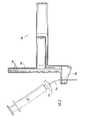
- FIG. 1Aillustrates an ultrasound device including a series of Hall effect sensors along a length of the ultrasound device.
- FIGS. 1B and 1Cillustrate two embodiments of arrays of Hall effect sensors as may be utilized in disclosed ultrasound devices.
- FIG. 2illustrates the ultrasound device of FIG. 1A upon deformation of a probe during use.
- FIG. 3Aillustrates an overlay of a FIGS. 1 and 2 .
- FIG. 3Billustrates a portion of FIG. 3A .
- FIGS. 4A and 4Bgraphically illustrate the change in the magnetic field strength along a sensor array for an aligned probe ( FIG. 4A ) and a probe that is flexed out of alignment ( FIG. 4B )
- FIG. 5Aillustrates an ultrasound device including a series of sensors on the base of the ultrasound device.
- FIG. 5Billustrates a top view of the ultrasound device of FIG. 5A .
- FIG. 5Cillustrates a top view of another embodiment of an array of sensors on the base of an ultrasound device.
- FIG. 6illustrates the ultrasound device of FIG. 5A upon deformation of a probe during use.
- FIG. 7illustrates a sterilizable shield that can encase an ultrasound device.
- FIG. 8illustrates the bottom portion of the sterilizable shield of FIG. 7 .
- FIG. 9illustrates the top portion of a sterilizable shield, the bottom portion of which is illustrated in FIG. 8 .
- FIG. 10illustrates another embodiment of an ultrasound device as disclosed herein.
- FIG. 11illustrates a partially exploded version of the ultrasound device as is illustrated in FIG. 10 .
- FIG. 12illustrates another embodiment of an ultrasound device as disclosed herein.
- FIG. 13illustrates a system as utilized in the Example, provided herein.
- FIG. 14illustrates a geometric description of a magnet tilt calculation model, as described herein.
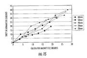
- FIG. 15graphically illustrates the shift in sensor readings upon flex in a probe as a function of the tilt of a target magnet.
- the term “probe”generally refers to an item that can be guided to a subdermal location, for instance for delivery of a therapeutic, e.g., a compound or a treatment, to the location; for removal of material from the location; and so forth.
- a therapeutice.g., a compound or a treatment
- the term “probe”can refer to a needle, a tube, a biopsy needle or blade, or any other item that can be guided to a subdermal location.
- a probecan be guided by and used in conjunction with an ultrasound device as described herein.
- a probecan define a ratio of the length of the probe to the diameter (or a width) of the probe greater than about 10.
- a probecan define any cross sectional shape, e.g., round, square, oblong, triangular, rectangular, etc.
- an ultrasound devicegenerally refers to a device that includes an ultrasound transducer therein and that can be utilized in conjunction with a probe, but does not necessarily include the probe itself.
- an ultrasound devicecan include a probe guide as an attachable or permanent component of the ultrasound device, and a probe can be utilized in conjunction with the ultrasound device to access a subdermal site by guiding the probe through the probe guide of the ultrasound device.
- ultrasound devices and methods for use in accurately forming a virtual image of a probe in conjunction with a sonogram during a medical procedurecan include a detector for detecting the location of a target associated with a probe while the probe is hold or moved within a probe guide of the ultrasound device.
- a detectorcan be in communication with a processor that can utilize information received from the detector with regard to target location and accurately identify the location of the probe tip based upon the information.
- a processorcan also be in communication with a monitor and can create an image of a virtual probe on the monitor, for instance in conjunction with a sonogram.
- disclosed ultrasound devicescan accurately correlate the image of the virtual probe tip with the location of the actual subdermal probe tip.
- a probecan be guided such that the probe tip approaches a subdermal site that can be visualized on the scanned plane of a sonogram.
- the probe tipcan travel on a path that defines a known correlation with sound waves emitted by the ultrasound transducer, e.g., coincident in the scanned plane, parallel to the scanned plane, or intersecting the scanned plane at a point.
- the path of the probe to the subdermal sitecan be known: the probe will advance toward the subdermal site on a straight line and at a predetermined angular relationship to the ultrasound housing base from the probe guide opening to the subdermal site that is imaged by the ultrasound.
- the path of the probe and the scanned plane of the sonogram imagecan both be defined by the orientation of the ultrasound transducer and can be coordinated on the subdermal site.
- the probe tipcan be guided along this known path the desired distance.
- an ultrasound devicecan be formed so as to be conveniently utilized by a single operator who can insert a probe using a probe guidance system and also control the ultrasound transducer so as to see the sonogram and a virtual image of the probe overlaid on the sonogram in real time during the procedure.
- An ultrasound devicecan incorporate a visualization system that can be used to create an image of a virtual probe that accurately correlates with the actual probe as it is being guided to a subdermal site and while it is being held at the site.
- a visualization systemcan be used to create an image of a virtual probe that accurately correlates with the actual probe as it is being guided to a subdermal site and while it is being held at the site.
- an ultrasound devicecan include a detector that can register the location of a target that is associated with the probe in the probe guide. This information can be electronically communicated to a processor and processed with input data (e.g., the length of the probe, etc.) and displayed as a real time image of a virtual probe in conjunction with a sonogram, i.e., the two images, the image developed from the data obtained by the detector, and the sonogram developed from the data obtained from the ultrasound transducer, can be displayed on the same monitor. Because the virtual probe location is correlated with the actual probe location, the location of the probe tip in relation to the subdermal site and the striking of the subdermal site by the probe tip can be seen in real time by an operator watching the virtual probe on the monitor during the procedure.
- input datae.g., the length of the probe, etc.
- a sonogrami.e., the two images, the image developed from the data obtained by the detector, and the sonogram developed from the data obtained from the ultrasound transducer
- any suitable detectorcan be utilized in disclosed devices for detecting the target that is associated with the probe.
- a detectorcan utilize infrared (IR), ultrasound, optical, laser, magnetic, or other detection mechanisms.
- IRinfrared
- the location of a detectoris not critical to a device, save that it is capable of detecting the target that is associated with the probe.
- the targetcan be any suitable item. It can be all or a portion of the probe itself, or can be directly or indirectly attached to the probe.
- FIG. 1Aillustrates one embodiment of a magnetic based detection system as may be utilized.
- an ultrasound device 200can include a handle 102 , a post 204 , and a base 206 .
- the base 206can define a probe guide 126 therethrough.
- An ultrasound transducer 110 that transmits and receives ultrasonic wavescan be located in base 106 .
- An ultrasound device 200can include a series of sensors 201 that form a detector along a length of post 204 . Sensors can be sensitive to the presence of a target 205 that can be attachable to a probe 254 which can be, for example, a needle.
- sensors 201can be Hall effect sensors that are sensitive to a magnetic field and target 205 can include one or more magnets.
- sensors 201can be Hall effect sensors that are sensitive to a magnetic field and target 205 can include one or more magnets.
- target 205can include one or more magnets.
- One exemplary embodiment of a magnetic based detection system as may be incorporated in disclosed devicesis describe in U.S. Pat. No. 6,690,159 to Burreson, et al., which is incorporated herein by reference.
- the sensors 201can be arranged in one or more rows extending lengthwise along the post 204 , which is the direction along which the probe will move during insertion, herein defined as the X direction, as shown in FIG. 1A .
- the presence of a magnetic fieldcan induce a voltage in a Hall effect sensor that is proportional to the size of the magnetic field.
- the voltage of each sensor 201can be electronically scanned and processed to determine the location of the target 205 relative to the sensing array (i.e., the detector). Processing can include grouping the sensors 201 and providing their outputs to a series of multiplexers which, in turn, are connected to a processor including software for analyzing the outputs and determining the location of the target 205 with regard to the entire sensor array. As the distance from the target 205 to the tip of the probe 254 is constant and known, the processor can likewise compute the location of the tip of probe 254 .
- the processing of the sensor outputscan include determining which sensor 201 has the highest (or lowest, depending upon the magnetic field orientation) voltage output in a recognized grouping, corresponding to the location of the magnetic target 205 .
- a processorcan analyze the output of the sensor having the highest voltage output and a predetermined number of sensor(s) to each side. The analog outputs of the sensors can be converted to digital output according to known methodology that can then be evaluated to determine the target location.
- a vector of values corresponding to the desired signalcan be mathematically correlated against the vector signal set from scanned sensors 201 .
- a peak in the correlation signalcan indicate the center of the desired sensor set to evaluate.
- the detection systemneed not utilize the peak signal and adjacent Hall sensors, but instead or in addition, sensors can evaluate the zero crossing signal that can result from using combinations of north and south magnets.
- the magnetic target 205can be mounted at the base of syringe 207 in conjunction with probe 254 .
- the magnetic target 205can be mounted on a base plate of magnetically permeable material.
- the magnetic flux linescan be concentrated in a direction away from the base plate.
- the greatest magnetic flux densitycan be present at the center of the magnet and extend perpendicular thereto, e.g., parallel to post 204 in the X direction.
- the flux densitydecreases as a near Gaussian distribution function as one proceeds away from the magnet center line in the plane of the magnet.
- the targetincorporates a magnet, with a magnetic field having a flux density which has a maximum at or adjacent to the center of the magnet and which decreases as a function of the distance moved away from the magnet.
- a single thin magnetcan be used, or an array of magnets located side by side. The magnet or array of magnets then can be mounted in conjunction with a probe 254 .
- the magnetic material of target 205can be any suitable material that has a high enough energy to be detectable over the distance between the target 205 and the sensors 201 .
- suitable materialscan include, without limitation, samarium cobalt, neodymium, or iron boron.
- a row of sensors 201can be placed side by side in a single row in the X direction along the post 204 , as illustrated in FIG. 1C .
- the sensors 201can be located close to each other.
- the distance between adjacent sensorscan be affected by connection pins, casings, housings in which they are mounted, etc.
- a small sensing componentcan be mounted in conjunction with pins or contacts that project from a housing for connection to a supply voltage, ground and output, respectively.
- This distancecan be reduced by providing an array of sensors that are canted at an angle to the sensing or X direction, and are provided in two rows with the sensors staggered relative to each other, as illustrated in FIG. 1B . This can decrease the center to center distance between adjacent sensing components for increased accuracy of a detector.
- the individual sensors 201 forming an array along post 204are likewise encompassed in the present disclosure.
- the Hall effect sensorscan operate at a typical supply voltage of about 5 volts.
- the sensorscan be designed to provide a known output voltage, e.g., about 2.5 volts, in the absence of a detectable magnetic field.
- the presence of a south pole magnetic fieldwill increase the output voltage above the output voltage by an amount proportional to the magnetic field applied within a predetermined range of magnetic field strength.
- the application of a north pole magnetic fieldwill decrease the output voltage from its quiescent value proportional to the magnetic field applied.
- the output voltagecan be directly correlated to the magnetic field strength.
- the output voltage of a sensorcan be directly correlated to the distance between the sensor and the magnet.
- all of the sensors 201can be mounted on a single printed circuit board.
- the printed circuit boardalso can include multiplexers for scanning of the outputs of the sensors. For example, in the case of 64 sensors, eight eight-port multiplexers can be used and coupled to a processor. A ninth multiplexer can be used to take the output of the eight multiplexers to one output for an analog-to-digital converter.
- Each multiplexercan receive the outputs from eight of the Hall effect sensors and can provide a selected output on a line to a processor.
- the processorcan include an analog-to-digital converter that, in combination with the multiplexers, scans the outputs of the sensors and converts the signals to digital form.
- the processing unitcan also store an algorithm by which the Hall array outputs (i.e., the location of the target) can be processed to determine the location of the tip of the probe relative to the sensor having the reading that locates that particular sensor closest to the center of the magnetic target 205 , for example, the sensor closest to the center of magnetic target can be the sensor obtaining the highest voltage output reading.
- processing of the outputs of the sensors 201is accomplished by scanning all sensor outputs and determining which of them has the highest value.
- highestmeans the maximum difference from the quiescent value, i.e., the degree to which the output voltage has been shifted up or down from the quiescent voltage of, e.g., 2.5 volts.
- Highest valuecan also refer to the point in the array where a predetermined signal vector produces the highest correlation against the scanned sensors.
- the outputs of a predetermined number of sensors at each side of the highest signalcan also be considered, such as three sensors at each side or four sensors at each side. The outputs of the remaining sensors can be ignored or can be incorporated, as desired.
- This predetermined number of outputscan then be used to calculate the location of the magnetic target 205 and also the tip of the probe 254 that is a known distance from the magnetic target 205 .
- the accuracy of the measurement in the X directioncan be maximized according any suitable methodology.
- the geometric arrangement of the sensorscan be optimized, as discussed above, to limit the space between adjacent sensors, and the processor algorithm or algorithms used to convert the input signals to distance measurement can be adjusted to reflect the highest voltage output from any individual sensor depending upon its geometric location in the array and with respect to the magnetic target at its closest proximity.
- Input information provided to a processing unitcan include information concerning the position of each individual sensor. This can be by sensor number, for example, “1,” “2,” . . . , “64” for a 64-sensor array, which then can be converted to a location value based on the position of that sensor along the length of the post 204 .
- sensor numberfor example, “1,” “2,” . . . , “64” for a 64-sensor array, which then can be converted to a location value based on the position of that sensor along the length of the post 204 .
- One simple algorithm for calculating the position of the probe tip from the selected outputsis represented as follows: The sensor having the highest output is labeled “S,” and the system is designed to consider the outputs of three sensors at each side. Accordingly, such additional sensors can be labeled S ⁇ 3, S ⁇ 2, S ⁇ 1, S+1, S+2 and S+3.
- the sensor numbercan be multiplied by its respective output, and the mean value determined for the selected sensors.
- This valuethen can be converted to a distance or location value for the tip of the probe, as the processing unit can include as input data the distance from the target magnetic material 205 to the probe tip. Similarly, if the conversion of sensor number to location already has been made, the location is weighted by the output of the corresponding sensor, and the mean value determined and used as the indication of the location of the probe tip.
- the above methodassumes linear proportionality in variation of magnetic field strength away from the target in the sensing direction.
- the variationis nonlinear, and more nearly a Gaussian distribution. Consequently, a more accurate result can be obtained by fitting the selected data to a nonlinear function such as a Gaussian distribution curve.
- one of the parametersis the mean of the Gaussian fit, which can correspond to the target location.
- Commercially available softwarecan be used to calculate an appropriate Gaussian distribution fit, such as TableCurve 2D, available from SPSS Inc.
- the algorithmcan include the step of calculating the Gaussian distribution fit and determining the mean.
- Gaussian distributioncan include the spread of the Gaussian signal and the amplitude. Spread calculations can be used for error correction or fault detection. If a given sensor or sensors influence the fit of a distribution curve beyond reasonable parameters, that sensor or sensors can be assumed to be providing erroneous data and be ignored.
- Approximate Gaussian distributionscan be calculated with as few as three sensors, i.e., a maximum strength sensor and one at each side. Using greater numbers of sensors to perform the calculation can increase accuracy, and can also allow more flexibility in ignoring sensors whose values vary unreasonably from other sensors in the calculation set, for error correction and fault detection purposes.
- Signals from the sensors 201can create a data stream which can be sent to a processor.
- a processing unitcan be internal or external to an ultrasound device 200 .
- data from sensorscan be sent to a standard lap top or desk top computer processor or part of a self-contained ultrasound device as is known in the art.
- a processorcan be loaded with suitable recognition and analysis software and can receive and analyze the stream of data from sensors.
- each ultrasound devicecan vary somewhat from ideal in placement and output of individual sensors used in a sensor array. This potential effect can be mitigated through determination of a voltage offset value for each sensor, and the inclusion of that value in the processor programming, such that the data obtained from each sensor is processed in conjunction with the voltage offset value for that sensor.
- each sensorcan be scanned in the absence of a magnetic field, and the amount of voltage offset, if any, can be determined for each sensor.
- This voltage offset valuecan take into account both any innate variation in output of the sensor as well as any variation due to slight mislocation of a sensor when being placed on an ultrasound device during manufacturing.
- the calculation of the position of the magnetic target along the sensor arraycan include the adjustment of a sensor output by its offset amount.
- the distance from the surface 108 to the probe guide exit at the top of base 206 and the location of the sensor array with reference to the probe guidecan vary slightly from one ultrasound device to another. This can be accounted for by including a value in the processor programming that represents this variation.
- S offsis utilized in the present disclosure to represent this variation. It includes two parts: one part is defined by the geometry of the ultrasound device and is the distance from the skin contacting surface of the device 108 at the exit of probe guide 126 to the beginning of the sensor array 103 (i.e., the farthest point of the sensor array from the base).
- the other componentis dependant upon the manufacturing precision: how accurate the sensor array was placed on the ultrasound device in relation to the surface of the ultrasound transducer. This component is variable and will be different for every manufactured probe, but this difference is very small. This value can be obtained by a calibration process and can be provided to the processor programming algorithm.
- An ultrasound devicecan also be programmed to include more than one S offs value, depending upon the application.
- an ultrasound devicecan be utilized with a sterilizable shield, so as to be used in a sterile procedure.
- a device 200can be enclosed within a shield, which can alter the value of S offs .
- Such variationscan be easily accounted for, however, for instance, by providing a switch on the ultrasound device, which can provide the input value for S offs to the processor, e.g., when the switch is set for a sterile application, the value for S offs takes into account the use of a shield about the ultrasound device 200 .
- FIG. 2illustrates the flexing of a probe 254 that could occur during use if, for instance, a user inadvertently pushes the syringe 207 away from post 204 during a procedure. As can be seen, this can cause the portion of the probe 254 above the probe guide to bend. As the probe is flexible, the probe will straighten within the probe guide and proceed to the subdermal site along the path defined by the probe guide. This flexibility of the probe during delivery can lead to sensor information provided to the processor that differs from when the probe is aligned with the probe guide, which in turn can cause the processor to present a false location of exactly where the tip of the probe is on a sonogram.
- FIG. 3Aoverlays a probe 207 a that is aligned with the probe guide 126 in the X direction and a probe 207 b that has been pushed a distance out of alignment and is flexed away from post 204 above the probe guide 126 .
- the magnetic target 205will be determined by the array of sensors 201 to be at the marked location A.
- the array of sensors 201will obtain a different view of the magnetic field, which can lead to the determination of the virtual probe tip at a point that differs from the location of the actual probe tip at the subdermal site.
- the highest magnetic field strengthcan be determined by the sensor array to be at B, rather than at A, when the probe is flexed. This can lead to an error in the correlation of the virtual probe image with the actual probe.
- the probe tip location of the virtual imageis determined by the processor based upon the combination of the location of the magnetic target as determined by the sensor array and the known distance between the magnetic target and the probe tip. Any flexing of the probe 254 does not effect the location of the actual subdermal probe tip, it merely tilts the magnet away from the post 204 .
- FIG. 3Billustrates in greater detail how the flexing of the probe can lead a system to locate a virtual probe tip at a location that varies from the location of the actual probe tip.
- This variationis affected by two distinct aspects.
- the magnetic field determination by the sensor arraywill locate that magnet at point B rather than at point A, as discussed. This will have the effect of placing the virtual probe tip above the actual probe tip (too shallow).
- the bending of the needlewill alter the geometry of the system, i.e., the length L B is longer than the length of the chord 239 of the bent probe.
- the straight projection of the bent probe segment back to the sensor arraywill locate the magnet at point C, as shown in FIG. 3B , rather than at point A (where the magnet is located when the probe is not bent). This will have the effect of placing the virtual probe tip beneath the actual probe tip (too deep).
- Disclosed systemscan take both of these affects in to account to accurately correlate a virtual image of a probe with the actual subdermal location of the probe.
- a set of correlation factors determined for a single ultrasound devicecan generally be applicable to all similar ultrasound devices (i.e., devices of a similar size and shape, a similar sensor array and location, etc.). Thus, a set of correlation factors need not be determined for every individual device (though this is certainly an optional embodiment). Rather, a set of correlation factors can be determined for a single type of device, and those correlation factors can then be incorporated in the processor algorithm for all ultrasound devices of a similar type.
- S 0 , S H , H, and L Bare as described above and a, b, c, and d are a set of correlation factors determined experimentally for each type of ultrasound device, an example of which is explained in further detail below.
- This general equationhas been determined experimentally by a best fit process, as described below. Beneficially, this equation can hold for any ultrasound device in which a probe that is ideally aligned with a probe guide and an ultrasound transducer as described herein can be bent out of alignment such that a portion of the probe is bent away from the detector. To accurately portray the location of the virtual probe tip on a formed image so that it is aligned with the actual subdermal location of the probe tip, this equation can be utilized by the processor software to correlate the measured value of S H with an aligned value S 0 .
- S His the value obtained by the sensor for the magnetic target location
- the measured parametere.g., voltage
- L B( S offs ⁇ S H ) ⁇ L C
- a value for S 0can be obtained in terms of parameters that are either predetermined for each ultrasound device (e.g., L C , S offs ) or determinable from the sensor reading (S H , H).
- correlation factors a, b, c, dcan be experimentally determined, as described in the examples section below.
- the correlation factorscan be:
- d0 or between about ⁇ 0.5 and about ⁇ 0.06, for instance about ⁇ 0.053.
- the correlation equationcan be included in the instruction provided to the processor in the form of software, and the location of a virtual probe tip imaged in conjunction with a sonogram can be correlated with the location of an actual subdermal probe tip.
- a devicecan include a warning signal to alert a user should the magnet be moved beyond a predetermined level. For instance, should a probe be flexed such that the level index H becomes greater than, e.g., 5 or 6, an alarm can be triggered by the processor, so as to alert a user that the probe has been moved out of the desired position.
- An alarmcan be visual, auditory, tactile, or any combination thereof. For instance, a signal light can be turned on should the level index determined at the processor exceed a predetermined value.
- correlation of the virtual probe location as determined by the motion detector with the actual probe locationcan be determined through examination of the individual sensor outputs.
- a plurality of sensorsare examined for determination of the location of the magnetic target.
- a number of sensors both above and below a central signali.e., that signal location corresponding to the magnet locus
- the variation of magnetic field strength in the sensors above and below the targetwill be known, and in one embodiment, can be generally equivalent to each other (see, e.g., FIG. 4A , which illustrates one embodiment of the magnetic field strength along the X-axis, with the magnet at point A).
- the magnetic field strengthcan decrease according to a Gaussian distribution in both directions from the highest signal at the center sensor to the individual sensors that are farther away from the highest signal strength. Even if the decrease above and below the highest signal strength is not equivalent, the ideal decrease in both directions can be known.
- the magnetic field strength variationUpon flexing of a probe away from the desired alignment, the magnetic field strength variation will be altered from the ideal distribution as the magnet and the magnetic field become tipped as compared to the sensors, as shown in FIG. 4B .
- this distribution curve and the variation from ideal of the magnetic field distribution curvecan be utilized in another embodiment to determine the amount of flex from the aligned position of a probe.
- FIG. 5Aillustrates sensors 301 located on the base 306 of ultrasound device 300 .
- Sensors 301can be on the surface of base 306 or within the base 306 , depending upon the sensor type, the materials of the base 306 and so forth.
- Sensors 301are directed toward a target 305 associated with probe 354 .
- Sensors 301can utilize any suitable format, e.g., optics, sonics, proximity sensors, magnetics, etc., and determine the distance from the sensors 301 to the target 305 .
- Input data to a processorcan include the distance from the target 305 to the tip of probe 354 so as to accurately portray the location of the actual probe in forming a virtual probe image.
- FIG. 5Billustrates a top view of the device including two sensors illustrated in FIG. 5A .
- ultrasound device 300includes two sensors 301 radially opposite one another across the probe guide opening 326 .
- the processorcan obtain data and determine that the distance from each sensor to the target is no longer equivalent, as it should be.
- the processorcan include a correlation algorithm, similar to that described above for a sensor array located on a post parallel to the aligned direction of probe travel, so as to accurately locate the tip of the virtual probe image. For instance, an S offs , as described above can be obtained for each device, based upon the variations in manufacturing between devices, and the measured sensor array result for the location of the target, S H , can be corrected to provide S 0 , i.e., what that result would be if the probe 354 were not flexed out of the aligned position.
- a series of correlation factors experimentally determined for an ultrasound devicecan be programmed into the processor for application to all devices of that same type. In other words, the correlation factors obtained can be a permanent part of the processor, and each processor need not be specifically reprogrammed for every device.
- An ultrasound devicecan include a plurality of sensors at the base.
- FIG. 5Cillustrates a top view of an embodiment in which an ultrasound device includes multiple sensors 301 surrounding a probe guide opening 329 .
- all of the sensorswill have an essentially identical reading as to distance from the sensor to the target. If the target is pushed in any direction and thus out of alignment, the sensors will register the target at a variety of different distances, alerting the processor to the misalignment.
- the correction algorithmcan be similar to that described above for a two-sensor system, but can incorporate additional parameters for the other sensors.
- a processing unitcan also include standard imaging software as is generally known in the art to receive data from an ultrasound transducer that is a part of the ultrasound device in addition to software that can process readings from a detector with regard to misalignment of a probe in the device, as described, and form a virtual image on a monitor that accurately portrays the location of the actual probe being inserted subdermally.
- Input data for the processorsuch as the length of the probe, offset values, correlation factors, and so forth, can be entered into the processor by the user at the time of use or can be preprogrammed into the system as default data, depending upon the nature of the data, as discussed.
- a processorcan calculate the position of the probe tip relative to the ultrasound transducer, relative to a sensor, relative to the skin contacting surface of the device, or relative to any other convenient reference point.
- a processorcan communicate this position information digitally to a monitor and the information can be displayed on the monitor such as in a numerical format or as a real time image of a virtual probe.
- this datacan be illustrated in conjunction with, e.g., overlaid on, the sonogram that displays an image of the subdermal site, such as a blood vessel.
- disclosed ultrasound devicescan be utilized to actually show the approach of a probe toward a subdermal site on a monitor throughout the entire procedure.
- disclosed devicescan be utilized to ensure the probe tip remains at the subdermal site during subsequent procedures. For example, as long as the detector is interacting with the target the virtual image of the probe can remain on the monitor. Thus, any motion of the probe tip in relation to the the subdermal site can be noted by an observer, even following the clamping of the probe within the probe guide.
- any type of ultrasound transducer as is generally known in the artcan be incorporated in ultrasound devices as disclosed herein.
- a piezoelectric transducer formed of one or more piezoelectric crystalline materials arranged in a two or three-dimensional arraycan be utilized.
- Such materialsgenerally include ferroelectric piezoceramic crystalline materials such as lead zirconate titanate (PZT).
- PZTlead zirconate titanate
- the elements that form the arraycan be individual electrode or electrode segments mounted on a single piezoelectric substrate, such as those described in U.S. Pat. No. 5,291,090 to Dias, which is incorporated herein by reference thereto.
- an ultrasound transducercan be formed of multiple elements.
- single crystal ultrasound transducersare also encompassed by the present disclosure.
- the use of a multiple element ultrasound transducercan be advantageous in certain embodiments, as the individual elements that make up the transducer array can be controlled so as to limit or prevent any break or edge effects in a sonogram.
- the firing sequence of individual crystalscan be manipulated through various control systems and prevent any possible ‘blind spots’ in a sonogram as well as to clarify the edges of individual biological structures in the sonogram.
- control systemsare generally known in the art and thus will not be described in detail.
- the scanned plane(i.e., the plane of the sonogram) can be the geometric central plane of the beam transmitted from the ultrasound transducer 110 .
- the path of a probe that is guided through probe guide opening 126can be within the scanned plane. This is not a requirement of the present disclosure, however.
- the path of a probe passing through probe guide opening 126can be at an angle to the scanned plane such that it intersects the scanned plane at a point.
- the line defined by the path of a probe passing through the probe guide opening 126can be at an angle of ⁇ 1° to the scanned plane in one embodiment, at an angle of ⁇ 0.6 degrees in another embodiment, or at a lesser or greater angle in another embodiment.
- a line defined by the path of a probe passing through the probe guide openingcan be at an angle of ⁇ 10, ° ⁇ 20°, ⁇ 45°, or even greater, in other embodiments.
- An ultrasound device as encompassed hereincan have any convenient geometry.
- handle 102can be set at an angle to post 204 so as to be comfortably held in the hand while the device is being utilized.
- handle 102is about 90° to post 204 , though this angle can be varied as desired.
- an ultrasound deviceneed not include an extending handle portion at all.
- the base 206 of an ultrasound devicecan also have any convenient geometry.
- the skin contacting surfaces 108can be angled, as illustrated, or can be planar from edge to edge.
- the angle of a skin contacting surface 108can vary from 0° to about 30°, or from about 10° to about 20° in another embodiment.
- a skin contact surfacecan define an angle opposite to that illustrated in FIG. 1 , i.e., the skin contacting surface 108 can be convex.
- a skin contacting surfacecan also include curvature, e.g., can define an arcuate profile along the length or width of the surface.
- the footprint shape of the skin contacting surface 108may be rectangular, round, oblong, triangular, etc.
- the skin contacting surface 108can be, e.g., between about 0.5 inches and about 6 inches on its greatest length. In one embodiment, the skin contacting surface 108 can be about 0.5 inches on its greatest width and can promote stability of the device during use. In other embodiments, it can be larger, however, such as about 1 inch on its greatest width, about 2 inches on its greatest width, or even larger.
- an ultrasound devicemay be particularly designed to fit specific locations of the anatomy.
- a devicemay be shaped to be utilized specifically for infraclavicular approach to the subclavian vein, approach to the internal jugular vein, specific biopsy procedures including, without limitation, breast biopsy, thyroid nodule biopsy, prostate biopsy, lymph node biopsy, and so forth, or some other specific use.
- Variations in shape for any particular applicationcan include, for example, a specific geometry for the footprint of a base, alteration in the size of post and/or handle, as well as variation in angles at which various elements of a device meet each other.
- An ultrasound devicecan be utilized in conjunction with a sterilizable shield, for instance in those embodiments in which a probe is intended for use in a sterile field.
- a sterilizable shieldcan be formed of sterilizable materials as are generally known in the art.
- a sterilizable shieldcan be formed of single-use materials such as polymeric materials, and the entire shield can be properly disposed of following a single use.
- a sterilizable shieldcan be utilized multiple times, in which case it can be formed of a material that can be properly sterilized between uses.
- a sterilizable shieldcan be formed of a moldable thermoplastic or thermoset polymeric material including, without limitation, polyester, polyvinyl chloride, polycarbonate, and so forth.
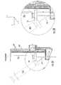
- FIG. 7illustrates one example of a sterilizable shield 130 as may be utilized to encase an ultrasound device.
- Sterilizable shield 130can include a lower section 132 , details of which are shown in FIG. 8 , and an upper section 134 , details of which are shown in FIG. 9 .
- shield section 132can include a base 136 formed of an ultrasonic transmissive material.
- Base 136can be of any suitable size and shape, but formed such that an ultrasound transducer housing base may be seated firmly in shield base 136 .
- a small amount of an ultrasonic gelcan be placed between the bottom surface of the transducer housing base and shield base 136 during seating to prevent any air between the two and promote transmission of ultrasonic waves.
- Guide post 138Arising out of shield base 136 is guide post 138 .
- Guide post 138defines at least a portion of a probe guide 139 therethrough.
- Probe guide 139extends uninterrupted completely through both guide post 138 and shield base 136 .
- Guide post 138can include tabs as shown, or other formations such as hooks, insets, or the like that can be utilized to properly assemble shield base 136 about an ultrasound transducer housing.
- guide post 138may include a removable cap (not shown) for protection of the interior sterile surface of probe guide 139 during assembly of shield 130 with an ultrasound transducer housing.
- section 134defines the terminal portion 151 of probe guide 139 . Terminal portion 151 is sized so as to snugly reside over the top of guide post 138 of section 132 and form uninterrupted probe guide 139 extending from the top surface of portion 160 of section 134 to the bottom surface of base 136 of section 132 .
- shield section 132can also include tabs 140 , 142 , 144 , etc. that can be utilized in properly seating an ultrasound housing within shield section 132 as well as aligning shield section 132 with shield section 134 when assembling the complete shield 130 about an ultrasound transducer housing.
- Tabs 140 on shield section 132can match corresponding notches 141 on shield section 134 shown in FIG. 9 . Together tabs 140 and notch 141 form a fastener that can secure shield section 132 and shield section 134 to one another. During assembly, tabs 140 can snap into notch 141 to securely fasten the two sections together and prevent separation of the sections 132 , 134 during use.
- a shieldcan include additional fasteners at other locations between the two sections, or can include a single fastener at an alternative location, as would be known to one of skill in the art.
- tabs 140can be simply pinched together and slid out of notch 141 .
- a single-use fastening mechanismcan be employed to secure sections of a sterilizable shield to one another.
- the tabs of the fastenerin order to disassemble a shield following use, can be permanently disabled upon disassembly of the shield.
- tabs 140 and/or notch 141can be permanently broken away from the shield by a pulling or twisting motion, allowing the shield sections to come apart and also ensuring that the shield, which is no longer sterile, cannot be utilized again. Any method that can ensure that a fastener can only be utilized a single time may alternatively be utilized.
- an ultrasound device 200 defining probe guide opening 126 shown in FIG. 1Acan be seated in section 132 of sterilizable shield 130 such that guide post 138 extends through transducer housing probe guide opening 126 .
- tabs on guide post 138can slide or snap into recesses of probe guide opening 126 (not shown), helping to properly seat ultrasound device 200 in section 132 .
- section 134can be aligned with section 132 and fastened into place to cover the top of ultrasound device 200 .
- a protective capcovers the end of guide post 138 , it can be removed during assembly and maintain the sterility of the interior of the probe guide 139 throughout the assembly process.
- Tabs 140can snap or slide into recesses notch 141 to fasten and secure section 132 and 134 together.
- probe guide 139can extend continuously from the top of portion 160 of shield portion 134 through the shield base 136 . Moreover, and of great benefit to the device, probe guide 139 can be sterile and within the probe guide opening 126 of ultrasound device 200 .
- a sterilizable shieldcan be hinged or can include additional sections, as desired.
- a sterilizable shieldcan be formed of two, three, or more separable sections that can be assembled to enclose all or a part of an ultrasound housing and form a sterile barrier between the enclosed housing and an exterior field.
- a sterilizable shieldcan be of a unitary construction.
- a sterilizable shieldcan be of a pliant material that can enclose all or a portion of an ultrasound housing and form a sterile barrier between the enclosed housing and an exterior field.
- the assembled sterilizable shield 130can also include a clamp 156 .
- clamp 156can firmly hold a probe 154 in the probe guide and prevent motion of the probe 154 during a procedure such as a catheter insertion, a biopsy procedure, fluid aspiration, or the like. Motion of the subdermal probe tip following insertion can be much less likely when the probe 154 is securely clamped to the probe guide of the sterilizable shield 130 and the ultrasound device is in turn held and stabilized by an operator as compared to devices in which a probe is simply held free-hand by an operator.
- a probe 154can extend through a probe guide (not shown) of sterilizable shield 130 .
- Clamp 156sits atop the base 161 of sterilizable shield 130 such that probe 154 passes through clamp aperture 158 as shown.
- Co-owned patent application Ser. No. 12/576,498 to Ridley, et al.which is incorporated by reference, describes one clamp as may be incorporated with an ultrasound device. Any other clamping action can alternatively be utilized.
- a clampcan tighten about a probe by a rotational motion of a clamping surface about a clamp, as is illustrated in U.S. Pat. No. 7,244,234 to Ridley, et al., which is incorporated herein by reference. Any relative motion between a clamp and a probe that can serve to firmly hold a probe in place through a friction hold, through physical interaction of probe/clamp segments, or through any combination thereof is encompassed in the present disclosure.
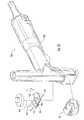
- FIG. 10illustrates another embodiment of an ultrasound device 800 that is encompassed by the present disclosure.
- ultrasound device 800can include a handle 802 , a post 804 , and a base 806 .
- Ultrasound device 800also defines a lower surface 810 , as shown.
- the ultrasound transducer housingdoes not include a probe guide opening.
- ultrasound device 800is removably attachable to a second portion that defines the probe guide opening.
- ultrasound device 800can be utilized in conjunction with a sterilizable shield that defines a probe guide.
- the sterilizable shieldcan be formed of a single or multiple removably attachable pieces.
- FIG. 11illustrates a sterilizable shield 930 that can be used in conjunction with an ultrasound device 800 illustrated in FIG. 10 .
- Sterilizable shield 930includes section 932 and section 961 , which defines a probe guide for passage of probe 954 therethrough. Additionally, section 932 can be separable into two or more section. Section 961 can also include clamp 956 defining aperture 958 and formations 962 , 963 . Clamp 956 can rotate about pivot 964 for clamping probe 954 in the probe guide.
- section 961can be attached to section 932 , for instance by use of aligned tabs and notches, and so forth, so as to attach the probe guide portion to the sterilizable shield.
- a section of an ultrasound device that does not define a probe guide openingcan be removably attached to a section that defines the probe guide opening and includes the clamp, without enclosing the entire device in a sterilizable shield.
- a sterilizable shield portioncan cover only the skin contacting surface of an ultrasound device.
- a shield portioncan snap onto the base of an ultrasound device.
- ultrasound device 1000does not include a handle portion. Such a device can be comfortably held by the rounded back portion 1002 , with the skin contacting surface 1110 held against a subject.
- Ultrasound device 1000can include some form of attachment, e.g., tabs, slots, hooks, etc, to attach a probe guide portion 1061 comprising clamp 1056 to device 1000 . When attached, the probe guide of portion 1061 can be aligned with an ultrasound transducer located in the base of ultrasound device 1000 .
- Exemplary applications for the devicescan include, without limitation
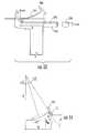
- FIG. 13An ultrasound device as illustrated in FIG. 13 was utilized.
- the needle probe 254was flexed away from the post 204 of the device, as shown.
- a sensor array 103 of Hall effect sensorswas located within the post 204 .
- the sensors usedwere ratiometric linear Hall effect sensors available from Allegro MicroSystems, Inc., model no. A1321.
- FIG. 13also provides a top view 270 of the post 204 , showing the curvature of the post to accommodate the target magnet 205 .
- the needle 254was flexed by increasing levels away from the post 204 .
- Sensor array readings, S Hwhich can be converted to a location parameter by simple geometric conversion based upon the ultrasound device, are provided in the Table 1, below. Data in each row were obtained with the same fixed position of the needle.
- FIG. 14illustrates a geometric model utilized to describe the tilt of a target magnet with the flexing of an attached probe from alignment with a probe guide.
- An assumptionwas made that the needle was bent with a constant radius of R. (In this example, the value for the level index, H, has been converted to the distance from the sensor array to the magnet.)
- L B68 mm
- L B58 mm
- L B48 mm 38 mm 28 mm 0 0 0 0 0 0 3.5 3.34 3.9 4.68 5.84 7.76 5.5 6.6 7.7 9.22 11.44 14.92 7.5 9.84 11.44 13.64 16.78 21.64 9.5 13.04 15.14 17.96 21.96 28 11.5 16.2 18.76 22.2 27.02 13.5 19.34 22.34 26.38
- Examples 1 and 2were combined to provide a graph ( FIG. 15 ) illustrating the experimentally obtained values for the shift in the sensor reading due to the flexing of the needle (S 0 ⁇ S H ) depend upon the angle of the flex, ⁇ .
- the sensor reading shiftcan not be explained only by the tilt of the magnet, this shift also depends upon the distance between the magnet and the sensors.
- Disclosed methodsprovide a route for accounting for this shift during the formation of a virtual image and correlating the position of a virtual image of a probe created on a monitor with the actual location of a subdermal probe.
- L B68 mm
- L B58 mm
- B48 mm 38 mm 28 mm 0 203
- 306404 501 597.5 3.5 199 296 397 493 588 5.5 196 293.5
- 486 581 7.5 194289.5
- 380474 565 9.5 192 285.5 376 470 558 11.5 189 281.5 373 464 13.5 184 276.5 371
- a device as illustrated in FIG. 13 including a detectorwas used.
- the detectorprovided the following readings:
- Example 3The system and correlation factors of Example 3 were utilized. Parameters measured by the detector included:
- This determined valuewas confirmed through actual measurement of the distance from the detector target to the tip of the needle.
Landscapes
- Health & Medical Sciences (AREA)
- Life Sciences & Earth Sciences (AREA)
- Surgery (AREA)
- Engineering & Computer Science (AREA)
- Medical Informatics (AREA)
- Animal Behavior & Ethology (AREA)
- Veterinary Medicine (AREA)
- Public Health (AREA)
- Biomedical Technology (AREA)
- Heart & Thoracic Surgery (AREA)
- General Health & Medical Sciences (AREA)
- Molecular Biology (AREA)
- Pathology (AREA)
- Nuclear Medicine, Radiotherapy & Molecular Imaging (AREA)
- Biophysics (AREA)
- Physics & Mathematics (AREA)
- Radiology & Medical Imaging (AREA)
- Gynecology & Obstetrics (AREA)
- Human Computer Interaction (AREA)
- Ultra Sonic Daignosis Equipment (AREA)
- Measurement Of Length, Angles, Or The Like Using Electric Or Magnetic Means (AREA)
- Length Measuring Devices Characterised By Use Of Acoustic Means (AREA)
Abstract
Description
- LB—Length of the bent portion of the probe (e.g., a needle).
- S0—The location of the magnetic target as would be determined by the sensor array were the probe to be properly aligned with the probe guide along the X axis.
- SH—The location of the magnetic target as determined by the sensor array when the probe is flexed out of this alignment.
- LC—The length of the probe guide as measured from the base surface of the
probe guide 108 to the top exit from the probe guide (where the probe begins to be bent out of alignment). - Soffs—The calibrated distance from the skin contacting surface of an ultrasound device to the distal end of the sensor array.
- H—A level index that represents the number of defined steps (or levels) out of alignment the probe is flexed. The level index H can be in any direction from the detector, i.e., in the Y axis, the Z axis or some combination thereof.
S0=SH+(a*H+c)LB+b*H+d
S0=SH+a*H*LB+b*H.
which incorporates only the a and b correlation factors. Similarly, the correlation equation can utilize only the a or the a, b, and c correlation factors in an equation. Moreover, additional factors can be incorporated in an equation, as would be known to one of skill in the art, with a improved alignment possible between the virtual probe tip and the actual probe tip when utilizing more correlation factors in the equation.
LB=(Soffs−SH)−LC
- Central Venous Catheterization
- Cardiac Catheterization (Central Arterial Access)
- Dialysis Catheter Placement
- Breast Biopsies
- Paracentesis
- Pericardiocentesis
- Thoracentesis
- Arthrocentesis
- Lumbar Puncture
- Epidural Catheter Placement
- Peripherally Inserted Central Catheter (PICC) line placement
- Thyroid Nodule Biopsies
- Cholecystic Drain Placement
- Amniocentesis
- Regional Anesthesia—Nerve Block
| TABLE 1 | |||||||||||||||||
| Level H | 0 | 1 | 2 | 3 | 4 | 5 | 6 | 7 | 8 | 9 | 10 | 11 | 12 | 13 | 14 | 15 | 16 |
| Meter | 702.5 | 699 | 696 | 692 | 689 | ||||||||||||
| readings | 611 | 608 | 605 | 602 | 599 | 596 | 594 | ||||||||||
| SH | 520 | 517 | 514 | 511 | 509 | 507 | 506 | 504 | 502 | 500 | 499 | 497 | 496 | ||||
| 460 | 458 | 455 | 453 | 451 | 449 | 447 | 446 | 444 | 443 | 442 | 441 | 440 | 439 | 437 | |||
| 401 | 399 | 397 | 394 | 393 | 391 | 389 | 386 | 384 | 383 | 381 | 380 | 378 | 377 | 376 | 375 | 374 | |
S0=SH+(a*H+c)*LB+b*H+d
- a=−0.051;
- b=4.31;
- c=0.0276;
- d=−0.534.
LB=R*α
h=2R*sin2(α/2)
h+RM=H+RM*cos(α)
- RMis the magnet radius (11 mm in this example).
- Thus,
H=[LB*sin2(α/2)]/α−RM*cos(α)
| TABLE 2 | |||||
| LB= | LB= | ||||
| H (mm) | LB= 68 mm | LB= 58 mm | LB= 48 mm | 38 mm | 28 mm |
| 0 | 0 | 0 | 0 | 0 | 0 |
| 3.5 | 3.34 | 3.9 | 4.68 | 5.84 | 7.76 |
| 5.5 | 6.6 | 7.7 | 9.22 | 11.44 | 14.92 |
| 7.5 | 9.84 | 11.44 | 13.64 | 16.78 | 21.64 |
| 9.5 | 13.04 | 15.14 | 17.96 | 21.96 | 28 |
| 11.5 | 16.2 | 18.76 | 22.2 | 27.02 | |
| 13.5 | 19.34 | 22.34 | 26.38 | ||
LB=(Soffs−SH)/10−LC,
S0=SH+(4.26−0.051*LB)*H,
| TABLE 3 | |||||
| LB= | LB= | ||||
| H (mm) | LB= 68 mm | LB= 58 mm | LB= 48 mm | 38 mm | 28 mm |
| 0 | 203 | 306 | 404 | 501 | 597.5 |
| 3.5 | 199 | 296 | 397 | 493 | 588 |
| 5.5 | 196 | 293.5 | 384 | 486 | 581 |
| 7.5 | 194 | 289.5 | 380 | 474 | 565 |
| 9.5 | 192 | 285.5 | 376 | 470 | 558 |
| 11.5 | 189 | 281.5 | 373 | 464 | |
| 13.5 | 184 | 276.5 | 371 | ||
- From equation 1:
LB=(685−400)/10+21.0=49.5 (mm) - From equation 2:
S0−SH=(4.26−0.051*49.5)*5=8.7
- From equation 1:
dLB=(S0−SH)/10=0.87 mm
more than is determined by the meter with no correlation of the reading SH. This determination was confirmed by actual measurement of the protrusion. Accordingly, when forming a virtual image of the needle on an ultrasound image, the location of the virtual needle tip can be accurately located with use of the correlation factors in the processing component of the system.
- SH=550
- H=3
LB=(685−550)/10+21.0=34.5 (mm)
S0−SH=(4.26−0.051*34.5)*3=7.5
and
dLB=(S0−SH)/10=0.75 mm
Claims (26)
S0=SH+(a*H+c)*LB+b*H+d
S0=SH+(a*H+c)*LB+b*H+d
Priority Applications (16)
| Application Number | Priority Date | Filing Date | Title |
|---|---|---|---|
| US12/885,832US8425425B2 (en) | 2010-09-20 | 2010-09-20 | Virtual image formation method for an ultrasound device |
| JP2013530207AJP2013537837A (en) | 2010-09-20 | 2011-09-19 | Virtual image forming method for ultrasonic apparatus |
| PCT/US2011/052089WO2012040077A1 (en) | 2010-09-20 | 2011-09-19 | Virtual image formation method for an ultrasound device |
| CA2811935ACA2811935A1 (en) | 2010-09-20 | 2011-09-19 | Virtual image formation method for an ultrasound device |
| EP11827281.4AEP2618740A1 (en) | 2010-09-20 | 2011-09-19 | Virtual image formation method for an ultrasound device |
| AU2011305699AAU2011305699A1 (en) | 2010-09-20 | 2011-09-19 | Virtual image formation method for an ultrasound device |
| US13/649,710US10610195B2 (en) | 2010-09-20 | 2012-10-11 | Probe and system for use with an ultrasound device |
| JP2016171549AJP6298126B2 (en) | 2010-09-20 | 2016-09-02 | Probe device |
| US15/372,812US11045165B2 (en) | 2010-09-20 | 2016-12-08 | Probe and system for use with an ultrasound device |
| JP2018023732AJP6847494B2 (en) | 2010-09-20 | 2018-02-14 | Ultrasonic system |
| JP2019231070AJP6971296B2 (en) | 2010-09-20 | 2019-12-23 | Virtual image formation method for ultrasonic equipment |
| US17/330,770US11134914B2 (en) | 2010-09-20 | 2021-05-26 | Probe and system for use with an ultrasound device |
| US17/330,587US11129589B1 (en) | 2010-09-20 | 2021-05-26 | Probe and system for use with an ultrasound device |
| US17/330,737US11129590B1 (en) | 2010-09-20 | 2021-05-26 | Probe and system for use with an ultrasound device |
| US17/330,643US11134913B1 (en) | 2010-09-20 | 2021-05-26 | Probe and system for use with an ultrasound device |
| US17/412,762US11207050B1 (en) | 2010-09-20 | 2021-08-26 | Probe and system for use with an ultrasound device |
Applications Claiming Priority (1)
| Application Number | Priority Date | Filing Date | Title |
|---|---|---|---|
| US12/885,832US8425425B2 (en) | 2010-09-20 | 2010-09-20 | Virtual image formation method for an ultrasound device |
Related Child Applications (2)
| Application Number | Title | Priority Date | Filing Date |
|---|---|---|---|
| US13/649,710ContinuationUS10610195B2 (en) | 2010-09-20 | 2012-10-11 | Probe and system for use with an ultrasound device |
| US13/649,710DivisionUS10610195B2 (en) | 2010-09-20 | 2012-10-11 | Probe and system for use with an ultrasound device |
Publications (2)
| Publication Number | Publication Date |
|---|---|
| US20120071759A1 US20120071759A1 (en) | 2012-03-22 |
| US8425425B2true US8425425B2 (en) | 2013-04-23 |
Family
ID=45818361
Family Applications (8)
| Application Number | Title | Priority Date | Filing Date |
|---|---|---|---|
| US12/885,832Active2031-03-19US8425425B2 (en) | 2010-09-20 | 2010-09-20 | Virtual image formation method for an ultrasound device |
| US13/649,710Active2032-03-26US10610195B2 (en) | 2010-09-20 | 2012-10-11 | Probe and system for use with an ultrasound device |
| US15/372,812Active2034-02-09US11045165B2 (en) | 2010-09-20 | 2016-12-08 | Probe and system for use with an ultrasound device |
| US17/330,770ActiveUS11134914B2 (en) | 2010-09-20 | 2021-05-26 | Probe and system for use with an ultrasound device |
| US17/330,587ActiveUS11129589B1 (en) | 2010-09-20 | 2021-05-26 | Probe and system for use with an ultrasound device |
| US17/330,737ActiveUS11129590B1 (en) | 2010-09-20 | 2021-05-26 | Probe and system for use with an ultrasound device |
| US17/330,643ActiveUS11134913B1 (en) | 2010-09-20 | 2021-05-26 | Probe and system for use with an ultrasound device |
| US17/412,762ActiveUS11207050B1 (en) | 2010-09-20 | 2021-08-26 | Probe and system for use with an ultrasound device |
Family Applications After (7)
| Application Number | Title | Priority Date | Filing Date |
|---|---|---|---|
| US13/649,710Active2032-03-26US10610195B2 (en) | 2010-09-20 | 2012-10-11 | Probe and system for use with an ultrasound device |
| US15/372,812Active2034-02-09US11045165B2 (en) | 2010-09-20 | 2016-12-08 | Probe and system for use with an ultrasound device |
| US17/330,770ActiveUS11134914B2 (en) | 2010-09-20 | 2021-05-26 | Probe and system for use with an ultrasound device |
| US17/330,587ActiveUS11129589B1 (en) | 2010-09-20 | 2021-05-26 | Probe and system for use with an ultrasound device |
| US17/330,737ActiveUS11129590B1 (en) | 2010-09-20 | 2021-05-26 | Probe and system for use with an ultrasound device |
| US17/330,643ActiveUS11134913B1 (en) | 2010-09-20 | 2021-05-26 | Probe and system for use with an ultrasound device |
| US17/412,762ActiveUS11207050B1 (en) | 2010-09-20 | 2021-08-26 | Probe and system for use with an ultrasound device |
Country Status (6)
| Country | Link |
|---|---|
| US (8) | US8425425B2 (en) |
| EP (1) | EP2618740A1 (en) |
| JP (4) | JP2013537837A (en) |
| AU (1) | AU2011305699A1 (en) |
| CA (1) | CA2811935A1 (en) |
| WO (1) | WO2012040077A1 (en) |
Cited By (40)
| Publication number | Priority date | Publication date | Assignee | Title |
|---|---|---|---|---|
| US20100317981A1 (en)* | 2009-06-12 | 2010-12-16 | Romedex International Srl | Catheter Tip Positioning Method |
| US8781555B2 (en) | 2007-11-26 | 2014-07-15 | C. R. Bard, Inc. | System for placement of a catheter including a signal-generating stylet |
| US8784336B2 (en) | 2005-08-24 | 2014-07-22 | C. R. Bard, Inc. | Stylet apparatuses and methods of manufacture |
| US8849382B2 (en) | 2007-11-26 | 2014-09-30 | C. R. Bard, Inc. | Apparatus and display methods relating to intravascular placement of a catheter |
| US8858455B2 (en) | 2006-10-23 | 2014-10-14 | Bard Access Systems, Inc. | Method of locating the tip of a central venous catheter |
| US9125578B2 (en) | 2009-06-12 | 2015-09-08 | Bard Access Systems, Inc. | Apparatus and method for catheter navigation and tip location |
| US9265443B2 (en) | 2006-10-23 | 2016-02-23 | Bard Access Systems, Inc. | Method of locating the tip of a central venous catheter |
| US9415188B2 (en) | 2010-10-29 | 2016-08-16 | C. R. Bard, Inc. | Bioimpedance-assisted placement of a medical device |
| US9445734B2 (en) | 2009-06-12 | 2016-09-20 | Bard Access Systems, Inc. | Devices and methods for endovascular electrography |
| US9456766B2 (en) | 2007-11-26 | 2016-10-04 | C. R. Bard, Inc. | Apparatus for use with needle insertion guidance system |
| US9492097B2 (en) | 2007-11-26 | 2016-11-15 | C. R. Bard, Inc. | Needle length determination and calibration for insertion guidance system |
| US9521961B2 (en) | 2007-11-26 | 2016-12-20 | C. R. Bard, Inc. | Systems and methods for guiding a medical instrument |
| US9532724B2 (en) | 2009-06-12 | 2017-01-03 | Bard Access Systems, Inc. | Apparatus and method for catheter navigation using endovascular energy mapping |
| US9554716B2 (en) | 2007-11-26 | 2017-01-31 | C. R. Bard, Inc. | Insertion guidance system for needles and medical components |
| US9636031B2 (en) | 2007-11-26 | 2017-05-02 | C.R. Bard, Inc. | Stylets for use with apparatus for intravascular placement of a catheter |
| US9649048B2 (en) | 2007-11-26 | 2017-05-16 | C. R. Bard, Inc. | Systems and methods for breaching a sterile field for intravascular placement of a catheter |
| US9681823B2 (en) | 2007-11-26 | 2017-06-20 | C. R. Bard, Inc. | Integrated system for intravascular placement of a catheter |
| US9839372B2 (en) | 2014-02-06 | 2017-12-12 | C. R. Bard, Inc. | Systems and methods for guidance and placement of an intravascular device |
| US9901714B2 (en) | 2008-08-22 | 2018-02-27 | C. R. Bard, Inc. | Catheter assembly including ECG sensor and magnetic assemblies |
| US9907513B2 (en) | 2008-10-07 | 2018-03-06 | Bard Access Systems, Inc. | Percutaneous magnetic gastrostomy |
| US10046139B2 (en) | 2010-08-20 | 2018-08-14 | C. R. Bard, Inc. | Reconfirmation of ECG-assisted catheter tip placement |
| USD837975S1 (en) | 2017-11-03 | 2019-01-08 | West Pharmaceutical Services, Inc. | Injection assist device |
| USD838360S1 (en) | 2017-11-06 | 2019-01-15 | West Pharmaceutical Services, Inc. | Injection assist device |
| US10178984B2 (en) | 2014-01-10 | 2019-01-15 | Soma Research, Llc | Needle guidance systems for use with ultrasound devices |
| USD842458S1 (en) | 2017-11-06 | 2019-03-05 | West Pharmaceutical Services, Inc. | Injection assist device |
| USD847976S1 (en) | 2017-11-06 | 2019-05-07 | West Pharmaceutical Services, Inc. | Injection assist device |
| USD847977S1 (en) | 2017-11-06 | 2019-05-07 | West Pharmaceutical Services, Inc. | Injection assist device |
| US10349890B2 (en) | 2015-06-26 | 2019-07-16 | C. R. Bard, Inc. | Connector interface for ECG-based catheter positioning system |
| USD854681S1 (en) | 2017-11-06 | 2019-07-23 | West Pharmaceutical Services, Inc. | Injection assist device |
| US10449330B2 (en) | 2007-11-26 | 2019-10-22 | C. R. Bard, Inc. | Magnetic element-equipped needle assemblies |
| US10524691B2 (en) | 2007-11-26 | 2020-01-07 | C. R. Bard, Inc. | Needle assembly including an aligned magnetic element |
| US20200245968A1 (en)* | 2017-10-11 | 2020-08-06 | Koninklijke Philips N.V. | Intelligent ultrasound-based fertility monitoring |
| US10751509B2 (en) | 2007-11-26 | 2020-08-25 | C. R. Bard, Inc. | Iconic representations for guidance of an indwelling medical device |
| US10973584B2 (en) | 2015-01-19 | 2021-04-13 | Bard Access Systems, Inc. | Device and method for vascular access |
| US10992079B2 (en) | 2018-10-16 | 2021-04-27 | Bard Access Systems, Inc. | Safety-equipped connection systems and methods thereof for establishing electrical connections |
| US11000207B2 (en) | 2016-01-29 | 2021-05-11 | C. R. Bard, Inc. | Multiple coil system for tracking a medical device |
| US11207050B1 (en)* | 2010-09-20 | 2021-12-28 | Soma Research, Llc | Probe and system for use with an ultrasound device |
| US11413429B2 (en) | 2016-06-01 | 2022-08-16 | Becton, Dickinson And Company | Medical devices, systems and methods utilizing permanent magnet and magnetizable feature |
| US11826522B2 (en) | 2016-06-01 | 2023-11-28 | Becton, Dickinson And Company | Medical devices, systems and methods utilizing permanent magnet and magnetizable feature |
| US11877839B2 (en) | 2016-06-01 | 2024-01-23 | Becton, Dickinson And Company | Invasive medical devices including magnetic region and systems and methods |
Families Citing this family (34)
| Publication number | Priority date | Publication date | Assignee | Title |
|---|---|---|---|---|
| US7728868B2 (en) | 2006-08-02 | 2010-06-01 | Inneroptic Technology, Inc. | System and method of providing real-time dynamic imagery of a medical procedure site using multiple modalities |
| WO2009094646A2 (en) | 2008-01-24 | 2009-07-30 | The University Of North Carolina At Chapel Hill | Methods, systems, and computer readable media for image guided ablation |
| US8340379B2 (en) | 2008-03-07 | 2012-12-25 | Inneroptic Technology, Inc. | Systems and methods for displaying guidance data based on updated deformable imaging data |
| US8641621B2 (en) | 2009-02-17 | 2014-02-04 | Inneroptic Technology, Inc. | Systems, methods, apparatuses, and computer-readable media for image management in image-guided medical procedures |
| US8554307B2 (en) | 2010-04-12 | 2013-10-08 | Inneroptic Technology, Inc. | Image annotation in image-guided medical procedures |
| US11464578B2 (en) | 2009-02-17 | 2022-10-11 | Inneroptic Technology, Inc. | Systems, methods, apparatuses, and computer-readable media for image management in image-guided medical procedures |
| US8690776B2 (en) | 2009-02-17 | 2014-04-08 | Inneroptic Technology, Inc. | Systems, methods, apparatuses, and computer-readable media for image guided surgery |
| ES2568225T3 (en) | 2011-09-06 | 2016-04-28 | Ezono Ag | Imaging probe and method to obtain position and / or orientation information |
| EP3689250B1 (en) | 2011-10-17 | 2022-12-07 | BFLY Operations, Inc. | Transmissive imaging and related apparatus and methods |
| US8670816B2 (en) | 2012-01-30 | 2014-03-11 | Inneroptic Technology, Inc. | Multiple medical device guidance |
| US9801611B2 (en) | 2012-11-15 | 2017-10-31 | University Of South Carolina | Ultrasound barrier devices and methods related thereto |
| US9257220B2 (en) | 2013-03-05 | 2016-02-09 | Ezono Ag | Magnetization device and method |
| GB201303917D0 (en) | 2013-03-05 | 2013-04-17 | Ezono Ag | System for image guided procedure |
| US9459087B2 (en) | 2013-03-05 | 2016-10-04 | Ezono Ag | Magnetic position detection system |
| US10314559B2 (en) | 2013-03-14 | 2019-06-11 | Inneroptic Technology, Inc. | Medical device guidance |
| US20140275990A1 (en)* | 2013-03-15 | 2014-09-18 | Soma Access Systems, Llc | Ultrasound Guidance System Including Tagged Probe Assembly |
| US9667889B2 (en) | 2013-04-03 | 2017-05-30 | Butterfly Network, Inc. | Portable electronic devices with integrated imaging capabilities |
| US9901406B2 (en) | 2014-10-02 | 2018-02-27 | Inneroptic Technology, Inc. | Affected region display associated with a medical device |
| US10188467B2 (en) | 2014-12-12 | 2019-01-29 | Inneroptic Technology, Inc. | Surgical guidance intersection display |
| US9949700B2 (en) | 2015-07-22 | 2018-04-24 | Inneroptic Technology, Inc. | Medical device approaches |
| CN105476720B (en)* | 2015-12-10 | 2017-09-22 | 中国人民解放军第四军医大学 | Device and method for judging PICC (peripherally inserted Central catheter) ectopic position |
| US9675319B1 (en) | 2016-02-17 | 2017-06-13 | Inneroptic Technology, Inc. | Loupe display |
| JP7076735B2 (en)* | 2016-05-03 | 2022-05-30 | テキサス メディカル センター | Tactile sensing device for lumbar puncture |
| US10278778B2 (en) | 2016-10-27 | 2019-05-07 | Inneroptic Technology, Inc. | Medical device navigation using a virtual 3D space |
| JP7071364B2 (en)* | 2016-12-07 | 2022-05-18 | セクレタリー・デパートメント・オブ・バイオテクノロジー | Equipment and methods for extracting and collecting tissue samples |
| US11259879B2 (en) | 2017-08-01 | 2022-03-01 | Inneroptic Technology, Inc. | Selective transparency to assist medical device navigation |
| EP3681405B1 (en)* | 2017-09-15 | 2025-07-09 | Elesta S.P.A. | Device and computer program for needle sonographic guidance in minimally invasive procedures |
| KR102016941B1 (en)* | 2017-09-26 | 2019-09-02 | 주식회사 에프씨유 | Ultrasonic probe for optimum postion of magnetic sensor |
| US11484365B2 (en) | 2018-01-23 | 2022-11-01 | Inneroptic Technology, Inc. | Medical image guidance |
| EP3930599B1 (en)* | 2019-02-26 | 2023-08-23 | Epidutech Ltd | System for decompression of spinal epidural space |
| CN112336455B (en)* | 2019-08-06 | 2022-05-24 | 深圳钮迈科技有限公司 | Simulated needle distribution system and method of tumor therapeutic apparatus |
| US11896286B2 (en)* | 2019-08-09 | 2024-02-13 | Biosense Webster (Israel) Ltd. | Magnetic and optical catheter alignment |
| CN113450364B (en)* | 2021-06-29 | 2022-05-13 | 湖南大学 | A method for extracting centerline of tree structure based on 3D flux model |
| TWI798040B (en)* | 2022-03-30 | 2023-04-01 | 國立成功大學 | Needle guidance device |
Citations (74)
| Publication number | Priority date | Publication date | Assignee | Title |
|---|---|---|---|---|
| US3868565A (en) | 1973-07-30 | 1975-02-25 | Jack Kuipers | Object tracking and orientation determination means, system and process |
| US3983474A (en) | 1975-02-21 | 1976-09-28 | Polhemus Navigation Sciences, Inc. | Tracking and determining orientation of object using coordinate transformation means, system and process |
| US4054881A (en) | 1976-04-26 | 1977-10-18 | The Austin Company | Remote object position locater |
| US4197855A (en) | 1977-04-04 | 1980-04-15 | Siemens Aktiengesellschaft | Device for measuring the location, the attitude and/or the change in location or, respectively, attitude of a rigid body in space |
| JPS5643941A (en) | 1979-09-18 | 1981-04-22 | Tokyo Shibaura Electric Co | Ultrasonic probe for perforation |
| JPS57122861A (en) | 1981-01-22 | 1982-07-30 | Tokyo Shibaura Electric Co | Exclusive sheet of ultrasonic probe for drilling |
| US4407294A (en) | 1982-01-07 | 1983-10-04 | Technicare Corporation | Ultrasound tissue probe localization system |
| US4422139A (en) | 1982-03-29 | 1983-12-20 | Rockwell International Corporation | Transformer coupled up-down converter |
| JPS597919A (en) | 1982-07-06 | 1984-01-17 | Olympus Optical Co Ltd | Positioning device of endoscope |
| JPS63195803A (en) | 1987-02-09 | 1988-08-12 | Matsushita Electric Ind Co Ltd | Rotating transformer device |
| JPH01110707A (en) | 1987-10-23 | 1989-04-27 | Hitachi Metals Ltd | Magnetic core |
| US4945305A (en) | 1986-10-09 | 1990-07-31 | Ascension Technology Corporation | Device for quantitatively measuring the relative position and orientation of two bodies in the presence of metals utilizing direct current magnetic fields |
| US5285154A (en) | 1991-10-15 | 1994-02-08 | Eldec Corporation | Saturable core proximity sensor aligned perpendicular to a magnet target having a plate and a non-magnetic metal housing |
| US5291090A (en) | 1992-12-17 | 1994-03-01 | Hewlett-Packard Company | Curvilinear interleaved longitudinal-mode ultrasound transducers |
| US5318025A (en) | 1992-04-01 | 1994-06-07 | General Electric Company | Tracking system to monitor the position and orientation of a device using multiplexed magnetic resonance detection |
| JPH06205776A (en) | 1993-01-11 | 1994-07-26 | Toshiba Corp | Ultrasonic diagnostic equipment |
| US5351004A (en) | 1991-10-15 | 1994-09-27 | Eldec Corporation | Saturable core proximity sensor including a flux director and a magnetic target element |
| JPH07506997A (en) | 1993-01-18 | 1995-08-03 | ダーデル,エリック | Blood vessel localization and puncture device |
| US5453686A (en) | 1993-04-08 | 1995-09-26 | Polhemus Incorporated | Pulsed-DC position and orientation measurement system |
| JPH08614A (en) | 1994-06-24 | 1996-01-09 | Hitachi Medical Corp | Paracentetic probe |
| JPH08229042A (en) | 1995-02-24 | 1996-09-10 | Fuji Photo Optical Co Ltd | Piercing ultrasonic probe |
| WO1997003609A1 (en) | 1995-07-16 | 1997-02-06 | Ultra-Guide Ltd. | Free-hand aiming of a needle guide |
| US5617857A (en) | 1995-06-06 | 1997-04-08 | Image Guided Technologies, Inc. | Imaging system having interactive medical instruments and methods |
| US5622170A (en)* | 1990-10-19 | 1997-04-22 | Image Guided Technologies, Inc. | Apparatus for determining the position and orientation of an invasive portion of a probe inside a three-dimensional body |
| US5647373A (en) | 1993-11-07 | 1997-07-15 | Ultra-Guide Ltd. | Articulated needle guide for ultrasound imaging and method of using same |
| JPH09322880A (en) | 1996-06-05 | 1997-12-16 | Asahi Optical Co Ltd | Guidance device for endoscope |
| JPH1057376A (en) | 1996-08-16 | 1998-03-03 | Ge Yokogawa Medical Syst Ltd | Stab needle position detection method, stab needle vibrating device, vibrating liquid injection device and ultrosonograph |
| US5767669A (en) | 1996-06-14 | 1998-06-16 | Ascension Technology Corporation | Magnetic field position and orientation measurement system with dynamic eddy current rejection |
| US5831260A (en) | 1996-09-10 | 1998-11-03 | Ascension Technology Corporation | Hybrid motion tracker |
| US5851183A (en) | 1990-10-19 | 1998-12-22 | St. Louis University | System for indicating the position of a surgical probe within a head on an image of the head |
| US5873828A (en)* | 1994-02-18 | 1999-02-23 | Olympus Optical Co., Ltd. | Ultrasonic diagnosis and treatment system |
| US6026818A (en) | 1998-03-02 | 2000-02-22 | Blair Port Ltd. | Tag and detection device |
| US6076007A (en) | 1997-08-19 | 2000-06-13 | Flying Null Limited | Surgical devices and their location |
| WO2000057767A2 (en) | 1999-03-31 | 2000-10-05 | Ultraguide Ltd. | Apparatus and methods for medical diagnostic and for medical guided interventions and therapy |
| WO2000063658A2 (en) | 1999-04-15 | 2000-10-26 | Ultraguide Ltd. | Apparatus and method for detecting the bending of medical invasive tools in medical interventions |
| US6138495A (en) | 1997-12-31 | 2000-10-31 | Ultraguide Ltd. | Calibration method and apparatus for calibrating position sensors on scanning transducers |
| US6233476B1 (en) | 1999-05-18 | 2001-05-15 | Mediguide Ltd. | Medical positioning system |
| US6296614B1 (en) | 1999-04-08 | 2001-10-02 | Rick L. Pruter | Needle guide for attachment to ultrasound transducer probe |
| US6309304B1 (en) | 1999-10-22 | 2001-10-30 | Crane Co. | Internal torque limiter for a parallel indexer |
| US6325759B1 (en) | 1999-09-23 | 2001-12-04 | Ultrasonix Medical Corporation | Ultrasound imaging system |
| US6332089B1 (en)* | 1996-02-15 | 2001-12-18 | Biosense, Inc. | Medical procedures and apparatus using intrabody probes |
| US6336899B1 (en) | 1998-10-14 | 2002-01-08 | Kabushiki Kaisha Toshiba | Ultrasonic diagnosis apparatus |
| JP2002112998A (en) | 2000-10-05 | 2002-04-16 | Toshiba Medical System Co Ltd | Ultrasonic puncture supporting apparatus |
| US6427079B1 (en) | 1999-08-09 | 2002-07-30 | Cormedica Corporation | Position and orientation measuring with magnetic fields |
| US6442417B1 (en) | 1999-11-29 | 2002-08-27 | The Board Of Trustees Of The Leland Stanford Junior University | Method and apparatus for transforming view orientations in image-guided surgery |
| US20020173719A1 (en) | 2001-05-15 | 2002-11-21 | U-Systems, Inc. | Method and system for ultrasound imaging of a biopsy needle |
| US6505062B1 (en) | 1998-02-09 | 2003-01-07 | Stereotaxis, Inc. | Method for locating magnetic implant by source field |
| US20030016006A1 (en) | 1999-11-01 | 2003-01-23 | Igor Khalfin | Method and apparatus for electromagnetic position and orientation tracking with distortion compensation employing modulated signal |
| US6517491B1 (en) | 2000-10-31 | 2003-02-11 | Koninklijke Philips Electronics N.V | Transducer with spatial sensor |
| US6553326B1 (en) | 2000-04-07 | 2003-04-22 | Northern Digital Inc. | Errors in systems using magnetic fields to locate objects |
| US20030078502A1 (en) | 2001-10-23 | 2003-04-24 | Olympus Optical Co., Ltd. | Device for examining a subject capable of marking a boundary range for insertion/retraction of an insertion/retraction member that is inserted in and retracted from the subject |
| US6554771B1 (en) | 2001-12-18 | 2003-04-29 | Koninklijke Philips Electronics N.V. | Position sensor in ultrasound transducer probe |
| US20030120155A1 (en) | 2001-08-16 | 2003-06-26 | Frank Sauer | Video-assistance for ultrasound guided needle biopsy |
| US20030120150A1 (en) | 2001-12-21 | 2003-06-26 | Assaf Govari | Wireless position sensor |
| US20030163142A1 (en) | 1997-11-27 | 2003-08-28 | Yoav Paltieli | System and method for guiding the movements of a device to a target particularly for medical applications |
| US6690159B2 (en) | 2000-09-28 | 2004-02-10 | Eldec Corporation | Position indicating system |
| US6690963B2 (en) | 1995-01-24 | 2004-02-10 | Biosense, Inc. | System for determining the location and orientation of an invasive medical instrument |
| US20040034297A1 (en) | 2002-08-13 | 2004-02-19 | General Electric Company | Medical device positioning system and method |
| US6724191B1 (en) | 2000-05-09 | 2004-04-20 | Admiralty Corporation | Systems and methods useful for detecting presence and/or location of various materials |
| US20040097805A1 (en) | 2002-11-19 | 2004-05-20 | Laurent Verard | Navigation system for cardiac therapies |
| US6774624B2 (en) | 2002-03-27 | 2004-08-10 | Ge Medical Systems Global Technology Company, Llc | Magnetic tracking system |
| US20040250819A1 (en) | 2003-03-27 | 2004-12-16 | Blair William A. | Apparatus and method for detecting objects using tags and wideband detection device |
| US20040260174A1 (en) | 2001-10-17 | 2004-12-23 | Keene Mark N | Metal detection apparatus |
| US6836745B2 (en) | 2000-07-26 | 2004-12-28 | Northern Digital Inc. | Method for determining the position of a sensor element |
| US6911008B2 (en) | 2003-02-19 | 2005-06-28 | Ultrasonix Medical Corporation | Compound ultrasound imaging method |
| US6977504B2 (en) | 2003-12-31 | 2005-12-20 | Calypso Medical Technologies, Inc. | Receiver used in marker localization sensing system using coherent detection |
| US20060243529A1 (en) | 2003-07-03 | 2006-11-02 | John Crane Safematic Oy | Arrangement in connection with central lubrication system |
| WO2006121877A2 (en)* | 2005-05-06 | 2006-11-16 | Artann Laboratories, Inc. | Method and dual-array transducer probe for real time mechanical imaging of prostate |
| US20070078334A1 (en) | 2005-10-04 | 2007-04-05 | Ascension Technology Corporation | DC magnetic-based position and orientation monitoring system for tracking medical instruments |
| US7244234B2 (en)* | 2003-11-11 | 2007-07-17 | Soma Development Llc | Ultrasound guided probe device and method of using same |
| US7274325B2 (en) | 2002-12-23 | 2007-09-25 | Ultrasonix Medical Corporation | Optimized method of performing spatial transformation |
| US20090314088A1 (en)* | 2008-06-09 | 2009-12-24 | Materials And Sensors Technologies, Inc. | Differential Ultrasonic Waveguide Cure Monitoring Probe |
| US20100049050A1 (en) | 2008-08-22 | 2010-02-25 | Ultrasonix Medical Corporation | Highly configurable medical ultrasound machine and related methods |
| US7785330B2 (en)* | 2006-09-11 | 2010-08-31 | Depuy Products, Inc. | Method and apparatus for distal targeting of locking screws in intramedullary nails |
Family Cites Families (78)
| Publication number | Priority date | Publication date | Assignee | Title |
|---|---|---|---|---|
| US5370675A (en) | 1992-08-12 | 1994-12-06 | Vidamed, Inc. | Medical probe device and method |
| US4567896A (en)* | 1984-01-20 | 1986-02-04 | Elscint, Inc. | Method and apparatus for calibrating a biopsy attachment for ultrasonic imaging apparatus |
| US4622644A (en) | 1984-05-10 | 1986-11-11 | Position Orientation Systems, Ltd. | Magnetic position and orientation measurement system |
| JPS63122911A (en)* | 1986-11-13 | 1988-05-26 | Kobe Steel Ltd | Position detector |
| US5078144A (en) | 1988-08-19 | 1992-01-07 | Olympus Optical Co. Ltd. | System for applying ultrasonic waves and a treatment instrument to a body part |
| JP3204542B2 (en) | 1992-07-24 | 2001-09-04 | 株式会社東芝 | Magnetic field source measurement device |
| US5425382A (en) | 1993-09-14 | 1995-06-20 | University Of Washington | Apparatus and method for locating a medical tube in the body of a patient |
| US5558091A (en) | 1993-10-06 | 1996-09-24 | Biosense, Inc. | Magnetic determination of position and orientation |
| US6019724A (en) | 1995-02-22 | 2000-02-01 | Gronningsaeter; Aage | Method for ultrasound guidance during clinical procedures |
| GB9506909D0 (en) | 1995-04-04 | 1995-05-24 | Scient Generics Ltd | Spatial magnetic interrogation system |
| US5842986A (en) | 1995-08-16 | 1998-12-01 | Proton Sciences Corp. | Ferromagnetic foreign body screening method and apparatus |
| US5944023A (en) | 1995-12-07 | 1999-08-31 | Sims Deltec, Inc. | Systems and methods for determining the location of an implanted device including a magnet |
| WO1997048438A2 (en) | 1996-06-17 | 1997-12-24 | Lucent Medical Systems, Inc. | Medical tube for insertion and detection within the body of a patient |
| US5971949A (en) | 1996-08-19 | 1999-10-26 | Angiosonics Inc. | Ultrasound transmission apparatus and method of using same |
| SE9603314D0 (en) | 1996-09-12 | 1996-09-12 | Siemens Elema Ab | Method and apparatus for determining the location of a catheter within the body of a patient |
| US6197001B1 (en) | 1996-09-27 | 2001-03-06 | Becton Dickinson And Company | Vascular access device |
| US5879297A (en) | 1997-05-08 | 1999-03-09 | Lucent Medical Systems, Inc. | System and method to determine the location and orientation of an indwelling medical device |
| US6129668A (en) | 1997-05-08 | 2000-10-10 | Lucent Medical Systems, Inc. | System and method to determine the location and orientation of an indwelling medical device |
| US6263230B1 (en) | 1997-05-08 | 2001-07-17 | Lucent Medical Systems, Inc. | System and method to determine the location and orientation of an indwelling medical device |
| US6138681A (en) | 1997-10-13 | 2000-10-31 | Light Sciences Limited Partnership | Alignment of external medical device relative to implanted medical device |
| IL122336A0 (en) | 1997-11-27 | 1998-04-05 | Ultra Guide Ltd | System and method for guiding the movements of a device to a target particularly for medical applications |
| US8644907B2 (en) | 1999-10-28 | 2014-02-04 | Medtronic Navigaton, Inc. | Method and apparatus for surgical navigation |
| GB9928695D0 (en) | 1999-12-03 | 2000-02-02 | Sinvent As | Tool navigator |
| US6690693B1 (en) | 2000-05-04 | 2004-02-10 | Agility Communications, Inc. | Power and wavelength control of sampled grating distributed Bragg reflector lasers |
| JP3679978B2 (en)* | 2000-06-16 | 2005-08-03 | 松下電器産業株式会社 | Ultrasonic diagnostic equipment |
| US6484118B1 (en) | 2000-07-20 | 2002-11-19 | Biosense, Inc. | Electromagnetic position single axis system |
| US6785571B2 (en) | 2001-03-30 | 2004-08-31 | Neil David Glossop | Device and method for registering a position sensor in an anatomical body |
| US6592520B1 (en) | 2001-07-31 | 2003-07-15 | Koninklijke Philips Electronics N.V. | Intravascular ultrasound imaging apparatus and method |
| US6733458B1 (en) | 2001-09-25 | 2004-05-11 | Acuson Corporation | Diagnostic medical ultrasound systems and methods using image based freehand needle guidance |
| KR20030058423A (en) | 2001-12-31 | 2003-07-07 | 주식회사 메디슨 | Method and apparatus for observing biopsy needle and guiding the same toward target object in three-dimensional ultrasound diagnostic system using interventional ultrasound |
| DE10225518B4 (en) | 2002-06-10 | 2004-07-08 | Rayonex Schwingungstechnik Gmbh | Method and device for controlling and determining the position of an instrument or device |
| US6936003B2 (en) | 2002-10-29 | 2005-08-30 | Given Imaging Ltd | In-vivo extendable element device and system, and method of use |
| US20040097803A1 (en) | 2002-11-20 | 2004-05-20 | Dorin Panescu | 3-D catheter localization using permanent magnets with asymmetrical properties about their longitudinal axis |
| US7662128B2 (en) | 2002-12-23 | 2010-02-16 | Salcudean Septimiu E | Steerable needle |
| US6936048B2 (en) | 2003-01-16 | 2005-08-30 | Charlotte-Mecklenburg Hospital Authority | Echogenic needle for transvaginal ultrasound directed reduction of uterine fibroids and an associated method |
| KR200338377Y1 (en)* | 2003-10-18 | 2004-01-13 | 김진경 | A ultrasound-prove apparatus with fluid-bag and needle-guide |
| EP1833390B1 (en) | 2004-12-09 | 2010-05-12 | Stryker Corporation | Wireless system for providing instrument and implant data to a surgical navigation unit |
| US20080214931A1 (en) | 2005-06-28 | 2008-09-04 | Timm Dickfeld | Method and System for Guiding a Probe in a Patient for a Medical Procedure |
| JP2007068989A (en)* | 2005-08-11 | 2007-03-22 | Toshiba Corp | Ultrasonic diagnostic device, ultrasonic probe and puncture adapter |
| CN100556367C (en)* | 2005-08-11 | 2009-11-04 | 株式会社东芝 | Ultrasonic diagnostic device, ultrasonic probe, and puncture adapter |
| US8147408B2 (en) | 2005-08-31 | 2012-04-03 | Sonosite, Inc. | Medical device guide locator |
| US7985184B2 (en)* | 2005-09-10 | 2011-07-26 | Artann Laboratories | Ultrasound-assisted drug-delivery method and system based on time reversal acoustics |
| WO2007040172A1 (en)* | 2005-10-04 | 2007-04-12 | Hitachi Medical Corporation | Ultrasonic probe and ultrasonic diagnostic device employing same |
| BRPI0621017A2 (en) | 2005-12-06 | 2011-11-29 | St Jude Medical Atrial Fibrill Div | tissue ablation electrode junction evaluation |
| JP4365841B2 (en) | 2006-08-21 | 2009-11-18 | オリンパス株式会社 | Ultrasonic diagnostic equipment |
| JP5121201B2 (en) | 2006-09-28 | 2013-01-16 | オリンパスメディカルシステムズ株式会社 | Detector position detection system |
| US20080214925A1 (en) | 2007-03-01 | 2008-09-04 | Civco Medical Instruments Co., Inc. | Device for precision positioning of instruments at a mri scanner |
| WO2008131017A2 (en) | 2007-04-16 | 2008-10-30 | C. R. Bard, Inc. | Guidewire-assisted catheter placement system |
| US8934961B2 (en) | 2007-05-18 | 2015-01-13 | Biomet Manufacturing, Llc | Trackable diagnostic scope apparatus and methods of use |
| US20100204614A1 (en) | 2007-06-26 | 2010-08-12 | Zurlin Technologies Holdings, Llc | Electronic snore recording device and associated methods |
| JP5416900B2 (en)* | 2007-11-22 | 2014-02-12 | 株式会社東芝 | Ultrasonic diagnostic apparatus and puncture support control program |
| US9636031B2 (en) | 2007-11-26 | 2017-05-02 | C.R. Bard, Inc. | Stylets for use with apparatus for intravascular placement of a catheter |
| ES2465915T3 (en)* | 2007-11-26 | 2014-06-09 | C.R. Bard, Inc. | Integrated system for intravascular catheter placement |
| US9649048B2 (en) | 2007-11-26 | 2017-05-16 | C. R. Bard, Inc. | Systems and methods for breaching a sterile field for intravascular placement of a catheter |
| US8849382B2 (en) | 2007-11-26 | 2014-09-30 | C. R. Bard, Inc. | Apparatus and display methods relating to intravascular placement of a catheter |
| US8781555B2 (en) | 2007-11-26 | 2014-07-15 | C. R. Bard, Inc. | System for placement of a catheter including a signal-generating stylet |
| US9521961B2 (en) | 2007-11-26 | 2016-12-20 | C. R. Bard, Inc. | Systems and methods for guiding a medical instrument |
| US8437833B2 (en) | 2008-10-07 | 2013-05-07 | Bard Access Systems, Inc. | Percutaneous magnetic gastrostomy |
| EP2358278B1 (en)* | 2008-12-08 | 2021-05-12 | Acist Medical Systems, Inc. | System and catheter for image guidance and methods thereof |
| US20100191224A1 (en) | 2008-12-15 | 2010-07-29 | C.R. Bard, Inc. | Magnetic detent mechanism for medical instruments |
| US8892191B2 (en) | 2009-03-08 | 2014-11-18 | Oprobe, Llc | Methods of determining motion and distance during medical and veterinary procedures |
| US8504139B2 (en) | 2009-03-10 | 2013-08-06 | Medtronic Xomed, Inc. | Navigating a surgical instrument |
| US9532724B2 (en) | 2009-06-12 | 2017-01-03 | Bard Access Systems, Inc. | Apparatus and method for catheter navigation using endovascular energy mapping |
| US8761862B2 (en) | 2009-10-09 | 2014-06-24 | Stephen F. Ridley | Ultrasound guided probe device and sterilizable shield for same |
| US8496592B2 (en) | 2009-10-09 | 2013-07-30 | Stephen F. Ridley | Clamp for a medical probe device |
| WO2011097312A1 (en) | 2010-02-02 | 2011-08-11 | C.R. Bard, Inc. | Apparatus and method for catheter navigation and tip location |
| US8483802B2 (en) | 2010-03-25 | 2013-07-09 | Medtronic, Inc. | Method and apparatus for guiding an external needle to an implantable device |
| EP4122385A1 (en) | 2010-05-28 | 2023-01-25 | C. R. Bard, Inc. | Insertion guidance system for needles and medical components |
| EP2912999B1 (en) | 2010-05-28 | 2022-06-29 | C. R. Bard, Inc. | Apparatus for use with needle insertion guidance system |
| US8532743B2 (en) | 2010-08-05 | 2013-09-10 | St. Jude Medical, Atrial Fibrillation Division, Inc. | Movable magnet for magnetically guided catheter |
| US8425425B2 (en) | 2010-09-20 | 2013-04-23 | M. Dexter Hagy | Virtual image formation method for an ultrasound device |
| ES2900584T3 (en) | 2010-12-23 | 2022-03-17 | Bard Access Systems Inc | System for guiding a rigid instrument |
| RU2609203C2 (en) | 2011-07-06 | 2017-01-30 | Си.Ар. Бард, Инк. | Determination and calibration of needle length for needle guidance system |
| ES2568225T3 (en) | 2011-09-06 | 2016-04-28 | Ezono Ag | Imaging probe and method to obtain position and / or orientation information |
| US20130296691A1 (en) | 2012-05-04 | 2013-11-07 | Ascension Technology Corporation | Magnetically tracked surgical needle assembly |
| RU2669621C2 (en) | 2012-09-28 | 2018-10-12 | Си. Ар. БАРД, ИНК. | Needle assembly including an aligned magnetic element |
| CA2887877A1 (en) | 2012-10-18 | 2014-04-24 | C.R. Bard, Inc. | Magnetic element-equipped needle assemblies |
| JP2015008777A (en) | 2013-06-27 | 2015-01-19 | ジーイー・メディカル・システムズ・グローバル・テクノロジー・カンパニー・エルエルシー | Ultrasonic diagnostic apparatus and control program for the same |
- 2010
- 2010-09-20USUS12/885,832patent/US8425425B2/enactiveActive
- 2011
- 2011-09-19AUAU2011305699Apatent/AU2011305699A1/ennot_activeAbandoned
- 2011-09-19CACA2811935Apatent/CA2811935A1/ennot_activeAbandoned
- 2011-09-19WOPCT/US2011/052089patent/WO2012040077A1/enactiveApplication Filing
- 2011-09-19JPJP2013530207Apatent/JP2013537837A/enactivePending
- 2011-09-19EPEP11827281.4Apatent/EP2618740A1/ennot_activeWithdrawn
- 2012
- 2012-10-11USUS13/649,710patent/US10610195B2/enactiveActive
- 2016
- 2016-09-02JPJP2016171549Apatent/JP6298126B2/enactiveActive
- 2016-12-08USUS15/372,812patent/US11045165B2/enactiveActive
- 2018
- 2018-02-14JPJP2018023732Apatent/JP6847494B2/enactiveActive
- 2019
- 2019-12-23JPJP2019231070Apatent/JP6971296B2/enactiveActive
- 2021
- 2021-05-26USUS17/330,770patent/US11134914B2/enactiveActive
- 2021-05-26USUS17/330,587patent/US11129589B1/enactiveActive
- 2021-05-26USUS17/330,737patent/US11129590B1/enactiveActive
- 2021-05-26USUS17/330,643patent/US11134913B1/enactiveActive
- 2021-08-26USUS17/412,762patent/US11207050B1/enactiveActive
Patent Citations (77)
| Publication number | Priority date | Publication date | Assignee | Title |
|---|---|---|---|---|
| US3868565A (en) | 1973-07-30 | 1975-02-25 | Jack Kuipers | Object tracking and orientation determination means, system and process |
| US3983474A (en) | 1975-02-21 | 1976-09-28 | Polhemus Navigation Sciences, Inc. | Tracking and determining orientation of object using coordinate transformation means, system and process |
| US4054881A (en) | 1976-04-26 | 1977-10-18 | The Austin Company | Remote object position locater |
| US4197855A (en) | 1977-04-04 | 1980-04-15 | Siemens Aktiengesellschaft | Device for measuring the location, the attitude and/or the change in location or, respectively, attitude of a rigid body in space |
| JPS5643941A (en) | 1979-09-18 | 1981-04-22 | Tokyo Shibaura Electric Co | Ultrasonic probe for perforation |
| JPS57122861A (en) | 1981-01-22 | 1982-07-30 | Tokyo Shibaura Electric Co | Exclusive sheet of ultrasonic probe for drilling |
| US4407294A (en) | 1982-01-07 | 1983-10-04 | Technicare Corporation | Ultrasound tissue probe localization system |
| US4422139A (en) | 1982-03-29 | 1983-12-20 | Rockwell International Corporation | Transformer coupled up-down converter |
| JPS597919A (en) | 1982-07-06 | 1984-01-17 | Olympus Optical Co Ltd | Positioning device of endoscope |
| US4945305A (en) | 1986-10-09 | 1990-07-31 | Ascension Technology Corporation | Device for quantitatively measuring the relative position and orientation of two bodies in the presence of metals utilizing direct current magnetic fields |
| JPS63195803A (en) | 1987-02-09 | 1988-08-12 | Matsushita Electric Ind Co Ltd | Rotating transformer device |
| JPH01110707A (en) | 1987-10-23 | 1989-04-27 | Hitachi Metals Ltd | Magnetic core |
| US5622170A (en)* | 1990-10-19 | 1997-04-22 | Image Guided Technologies, Inc. | Apparatus for determining the position and orientation of an invasive portion of a probe inside a three-dimensional body |
| US5851183A (en) | 1990-10-19 | 1998-12-22 | St. Louis University | System for indicating the position of a surgical probe within a head on an image of the head |
| US5285154A (en) | 1991-10-15 | 1994-02-08 | Eldec Corporation | Saturable core proximity sensor aligned perpendicular to a magnet target having a plate and a non-magnetic metal housing |
| US5351004A (en) | 1991-10-15 | 1994-09-27 | Eldec Corporation | Saturable core proximity sensor including a flux director and a magnetic target element |
| US5318025A (en) | 1992-04-01 | 1994-06-07 | General Electric Company | Tracking system to monitor the position and orientation of a device using multiplexed magnetic resonance detection |
| US5291090A (en) | 1992-12-17 | 1994-03-01 | Hewlett-Packard Company | Curvilinear interleaved longitudinal-mode ultrasound transducers |
| JPH06205776A (en) | 1993-01-11 | 1994-07-26 | Toshiba Corp | Ultrasonic diagnostic equipment |
| JPH07506997A (en) | 1993-01-18 | 1995-08-03 | ダーデル,エリック | Blood vessel localization and puncture device |
| US5453686A (en) | 1993-04-08 | 1995-09-26 | Polhemus Incorporated | Pulsed-DC position and orientation measurement system |
| US5647373A (en) | 1993-11-07 | 1997-07-15 | Ultra-Guide Ltd. | Articulated needle guide for ultrasound imaging and method of using same |
| US5873828A (en)* | 1994-02-18 | 1999-02-23 | Olympus Optical Co., Ltd. | Ultrasonic diagnosis and treatment system |
| JPH08614A (en) | 1994-06-24 | 1996-01-09 | Hitachi Medical Corp | Paracentetic probe |
| US6690963B2 (en) | 1995-01-24 | 2004-02-10 | Biosense, Inc. | System for determining the location and orientation of an invasive medical instrument |
| JPH08229042A (en) | 1995-02-24 | 1996-09-10 | Fuji Photo Optical Co Ltd | Piercing ultrasonic probe |
| US5617857A (en) | 1995-06-06 | 1997-04-08 | Image Guided Technologies, Inc. | Imaging system having interactive medical instruments and methods |
| WO1997003609A1 (en) | 1995-07-16 | 1997-02-06 | Ultra-Guide Ltd. | Free-hand aiming of a needle guide |
| US6332089B1 (en)* | 1996-02-15 | 2001-12-18 | Biosense, Inc. | Medical procedures and apparatus using intrabody probes |
| JPH09322880A (en) | 1996-06-05 | 1997-12-16 | Asahi Optical Co Ltd | Guidance device for endoscope |
| US5767669A (en) | 1996-06-14 | 1998-06-16 | Ascension Technology Corporation | Magnetic field position and orientation measurement system with dynamic eddy current rejection |
| JPH1057376A (en) | 1996-08-16 | 1998-03-03 | Ge Yokogawa Medical Syst Ltd | Stab needle position detection method, stab needle vibrating device, vibrating liquid injection device and ultrosonograph |
| US5831260A (en) | 1996-09-10 | 1998-11-03 | Ascension Technology Corporation | Hybrid motion tracker |
| US6076007A (en) | 1997-08-19 | 2000-06-13 | Flying Null Limited | Surgical devices and their location |
| US20030163142A1 (en) | 1997-11-27 | 2003-08-28 | Yoav Paltieli | System and method for guiding the movements of a device to a target particularly for medical applications |
| US6138495A (en) | 1997-12-31 | 2000-10-31 | Ultraguide Ltd. | Calibration method and apparatus for calibrating position sensors on scanning transducers |
| US6604404B2 (en) | 1997-12-31 | 2003-08-12 | Ultraguide Ltd. | Calibration method and apparatus for calibrating position sensors on scanning transducers |
| US6505062B1 (en) | 1998-02-09 | 2003-01-07 | Stereotaxis, Inc. | Method for locating magnetic implant by source field |
| US6026818A (en) | 1998-03-02 | 2000-02-22 | Blair Port Ltd. | Tag and detection device |
| US6336899B1 (en) | 1998-10-14 | 2002-01-08 | Kabushiki Kaisha Toshiba | Ultrasonic diagnosis apparatus |
| WO2000057767A2 (en) | 1999-03-31 | 2000-10-05 | Ultraguide Ltd. | Apparatus and methods for medical diagnostic and for medical guided interventions and therapy |
| US6296614B1 (en) | 1999-04-08 | 2001-10-02 | Rick L. Pruter | Needle guide for attachment to ultrasound transducer probe |
| US6626832B1 (en) | 1999-04-15 | 2003-09-30 | Ultraguide Ltd. | Apparatus and method for detecting the bending of medical invasive tools in medical interventions |
| WO2000063658A2 (en) | 1999-04-15 | 2000-10-26 | Ultraguide Ltd. | Apparatus and method for detecting the bending of medical invasive tools in medical interventions |
| US6233476B1 (en) | 1999-05-18 | 2001-05-15 | Mediguide Ltd. | Medical positioning system |
| US6427079B1 (en) | 1999-08-09 | 2002-07-30 | Cormedica Corporation | Position and orientation measuring with magnetic fields |
| US6325759B1 (en) | 1999-09-23 | 2001-12-04 | Ultrasonix Medical Corporation | Ultrasound imaging system |
| US20020007119A1 (en) | 1999-09-23 | 2002-01-17 | Ultrasonix Medical Corporation | Ultrasound imaging system |
| US6309304B1 (en) | 1999-10-22 | 2001-10-30 | Crane Co. | Internal torque limiter for a parallel indexer |
| US20030016006A1 (en) | 1999-11-01 | 2003-01-23 | Igor Khalfin | Method and apparatus for electromagnetic position and orientation tracking with distortion compensation employing modulated signal |
| US6442417B1 (en) | 1999-11-29 | 2002-08-27 | The Board Of Trustees Of The Leland Stanford Junior University | Method and apparatus for transforming view orientations in image-guided surgery |
| US6553326B1 (en) | 2000-04-07 | 2003-04-22 | Northern Digital Inc. | Errors in systems using magnetic fields to locate objects |
| US6724191B1 (en) | 2000-05-09 | 2004-04-20 | Admiralty Corporation | Systems and methods useful for detecting presence and/or location of various materials |
| US6836745B2 (en) | 2000-07-26 | 2004-12-28 | Northern Digital Inc. | Method for determining the position of a sensor element |
| US6690159B2 (en) | 2000-09-28 | 2004-02-10 | Eldec Corporation | Position indicating system |
| JP2002112998A (en) | 2000-10-05 | 2002-04-16 | Toshiba Medical System Co Ltd | Ultrasonic puncture supporting apparatus |
| US6517491B1 (en) | 2000-10-31 | 2003-02-11 | Koninklijke Philips Electronics N.V | Transducer with spatial sensor |
| US20020173719A1 (en) | 2001-05-15 | 2002-11-21 | U-Systems, Inc. | Method and system for ultrasound imaging of a biopsy needle |
| US20030120155A1 (en) | 2001-08-16 | 2003-06-26 | Frank Sauer | Video-assistance for ultrasound guided needle biopsy |
| US20040260174A1 (en) | 2001-10-17 | 2004-12-23 | Keene Mark N | Metal detection apparatus |
| US20030078502A1 (en) | 2001-10-23 | 2003-04-24 | Olympus Optical Co., Ltd. | Device for examining a subject capable of marking a boundary range for insertion/retraction of an insertion/retraction member that is inserted in and retracted from the subject |
| US6554771B1 (en) | 2001-12-18 | 2003-04-29 | Koninklijke Philips Electronics N.V. | Position sensor in ultrasound transducer probe |
| US20030120150A1 (en) | 2001-12-21 | 2003-06-26 | Assaf Govari | Wireless position sensor |
| US6774624B2 (en) | 2002-03-27 | 2004-08-10 | Ge Medical Systems Global Technology Company, Llc | Magnetic tracking system |
| US20040034297A1 (en) | 2002-08-13 | 2004-02-19 | General Electric Company | Medical device positioning system and method |
| US20040097805A1 (en) | 2002-11-19 | 2004-05-20 | Laurent Verard | Navigation system for cardiac therapies |
| US7274325B2 (en) | 2002-12-23 | 2007-09-25 | Ultrasonix Medical Corporation | Optimized method of performing spatial transformation |
| US6911008B2 (en) | 2003-02-19 | 2005-06-28 | Ultrasonix Medical Corporation | Compound ultrasound imaging method |
| US20040250819A1 (en) | 2003-03-27 | 2004-12-16 | Blair William A. | Apparatus and method for detecting objects using tags and wideband detection device |
| US20060243529A1 (en) | 2003-07-03 | 2006-11-02 | John Crane Safematic Oy | Arrangement in connection with central lubrication system |
| US7244234B2 (en)* | 2003-11-11 | 2007-07-17 | Soma Development Llc | Ultrasound guided probe device and method of using same |
| US6977504B2 (en) | 2003-12-31 | 2005-12-20 | Calypso Medical Technologies, Inc. | Receiver used in marker localization sensing system using coherent detection |
| WO2006121877A2 (en)* | 2005-05-06 | 2006-11-16 | Artann Laboratories, Inc. | Method and dual-array transducer probe for real time mechanical imaging of prostate |
| US20070078334A1 (en) | 2005-10-04 | 2007-04-05 | Ascension Technology Corporation | DC magnetic-based position and orientation monitoring system for tracking medical instruments |
| US7785330B2 (en)* | 2006-09-11 | 2010-08-31 | Depuy Products, Inc. | Method and apparatus for distal targeting of locking screws in intramedullary nails |
| US20090314088A1 (en)* | 2008-06-09 | 2009-12-24 | Materials And Sensors Technologies, Inc. | Differential Ultrasonic Waveguide Cure Monitoring Probe |
| US20100049050A1 (en) | 2008-08-22 | 2010-02-25 | Ultrasonix Medical Corporation | Highly configurable medical ultrasound machine and related methods |
Non-Patent Citations (7)
| Title |
|---|
| 3D Guidance medSAFE Information Sheet, Copyright Ascension Technology Corporation Jan. 2009. |
| A1321/A1322/A1323 Product Information Sheet, Copyright 2004, 2005, Allegro MicroSystems, Inc. |
| Abstract-JP06205776A, Ultrasound Diagnostic System, Jul. 26, 1994. |
| Abstract—JP06205776A, Ultrasound Diagnostic System, Jul. 26, 1994. |
| JP App. No. 2006539726 Office Action dated Jun. 1, 2010. |
| JP App. No. 2006539726 Office Action dated Sep. 28, 2010. |
| Related Applications Form. |
Cited By (74)
| Publication number | Priority date | Publication date | Assignee | Title |
|---|---|---|---|---|
| US10004875B2 (en) | 2005-08-24 | 2018-06-26 | C. R. Bard, Inc. | Stylet apparatuses and methods of manufacture |
| US8784336B2 (en) | 2005-08-24 | 2014-07-22 | C. R. Bard, Inc. | Stylet apparatuses and methods of manufacture |
| US11207496B2 (en) | 2005-08-24 | 2021-12-28 | C. R. Bard, Inc. | Stylet apparatuses and methods of manufacture |
| US9345422B2 (en) | 2006-10-23 | 2016-05-24 | Bard Acess Systems, Inc. | Method of locating the tip of a central venous catheter |
| US9833169B2 (en) | 2006-10-23 | 2017-12-05 | Bard Access Systems, Inc. | Method of locating the tip of a central venous catheter |
| US8858455B2 (en) | 2006-10-23 | 2014-10-14 | Bard Access Systems, Inc. | Method of locating the tip of a central venous catheter |
| US9265443B2 (en) | 2006-10-23 | 2016-02-23 | Bard Access Systems, Inc. | Method of locating the tip of a central venous catheter |
| US9636031B2 (en) | 2007-11-26 | 2017-05-02 | C.R. Bard, Inc. | Stylets for use with apparatus for intravascular placement of a catheter |
| US11123099B2 (en) | 2007-11-26 | 2021-09-21 | C. R. Bard, Inc. | Apparatus for use with needle insertion guidance system |
| US11529070B2 (en) | 2007-11-26 | 2022-12-20 | C. R. Bard, Inc. | System and methods for guiding a medical instrument |
| US11779240B2 (en) | 2007-11-26 | 2023-10-10 | C. R. Bard, Inc. | Systems and methods for breaching a sterile field for intravascular placement of a catheter |
| US9456766B2 (en) | 2007-11-26 | 2016-10-04 | C. R. Bard, Inc. | Apparatus for use with needle insertion guidance system |
| US9492097B2 (en) | 2007-11-26 | 2016-11-15 | C. R. Bard, Inc. | Needle length determination and calibration for insertion guidance system |
| US9521961B2 (en) | 2007-11-26 | 2016-12-20 | C. R. Bard, Inc. | Systems and methods for guiding a medical instrument |
| US9526440B2 (en) | 2007-11-26 | 2016-12-27 | C.R. Bard, Inc. | System for placement of a catheter including a signal-generating stylet |
| US11134915B2 (en) | 2007-11-26 | 2021-10-05 | C. R. Bard, Inc. | System for placement of a catheter including a signal-generating stylet |
| US9549685B2 (en) | 2007-11-26 | 2017-01-24 | C. R. Bard, Inc. | Apparatus and display methods relating to intravascular placement of a catheter |
| US9554716B2 (en) | 2007-11-26 | 2017-01-31 | C. R. Bard, Inc. | Insertion guidance system for needles and medical components |
| US10342575B2 (en) | 2007-11-26 | 2019-07-09 | C. R. Bard, Inc. | Apparatus for use with needle insertion guidance system |
| US9649048B2 (en) | 2007-11-26 | 2017-05-16 | C. R. Bard, Inc. | Systems and methods for breaching a sterile field for intravascular placement of a catheter |
| US9681823B2 (en) | 2007-11-26 | 2017-06-20 | C. R. Bard, Inc. | Integrated system for intravascular placement of a catheter |
| US8849382B2 (en) | 2007-11-26 | 2014-09-30 | C. R. Bard, Inc. | Apparatus and display methods relating to intravascular placement of a catheter |
| US11707205B2 (en) | 2007-11-26 | 2023-07-25 | C. R. Bard, Inc. | Integrated system for intravascular placement of a catheter |
| US10449330B2 (en) | 2007-11-26 | 2019-10-22 | C. R. Bard, Inc. | Magnetic element-equipped needle assemblies |
| US10238418B2 (en) | 2007-11-26 | 2019-03-26 | C. R. Bard, Inc. | Apparatus for use with needle insertion guidance system |
| US9999371B2 (en) | 2007-11-26 | 2018-06-19 | C. R. Bard, Inc. | Integrated system for intravascular placement of a catheter |
| US8781555B2 (en) | 2007-11-26 | 2014-07-15 | C. R. Bard, Inc. | System for placement of a catheter including a signal-generating stylet |
| US10524691B2 (en) | 2007-11-26 | 2020-01-07 | C. R. Bard, Inc. | Needle assembly including an aligned magnetic element |
| US10105121B2 (en) | 2007-11-26 | 2018-10-23 | C. R. Bard, Inc. | System for placement of a catheter including a signal-generating stylet |
| US10165962B2 (en) | 2007-11-26 | 2019-01-01 | C. R. Bard, Inc. | Integrated systems for intravascular placement of a catheter |
| US10966630B2 (en) | 2007-11-26 | 2021-04-06 | C. R. Bard, Inc. | Integrated system for intravascular placement of a catheter |
| US10849695B2 (en) | 2007-11-26 | 2020-12-01 | C. R. Bard, Inc. | Systems and methods for breaching a sterile field for intravascular placement of a catheter |
| US10751509B2 (en) | 2007-11-26 | 2020-08-25 | C. R. Bard, Inc. | Iconic representations for guidance of an indwelling medical device |
| US10602958B2 (en) | 2007-11-26 | 2020-03-31 | C. R. Bard, Inc. | Systems and methods for guiding a medical instrument |
| US10231753B2 (en) | 2007-11-26 | 2019-03-19 | C. R. Bard, Inc. | Insertion guidance system for needles and medical components |
| US11027101B2 (en) | 2008-08-22 | 2021-06-08 | C. R. Bard, Inc. | Catheter assembly including ECG sensor and magnetic assemblies |
| US9901714B2 (en) | 2008-08-22 | 2018-02-27 | C. R. Bard, Inc. | Catheter assembly including ECG sensor and magnetic assemblies |
| US9907513B2 (en) | 2008-10-07 | 2018-03-06 | Bard Access Systems, Inc. | Percutaneous magnetic gastrostomy |
| US10231643B2 (en) | 2009-06-12 | 2019-03-19 | Bard Access Systems, Inc. | Apparatus and method for catheter navigation and tip location |
| US10912488B2 (en) | 2009-06-12 | 2021-02-09 | Bard Access Systems, Inc. | Apparatus and method for catheter navigation and tip location |
| US11419517B2 (en) | 2009-06-12 | 2022-08-23 | Bard Access Systems, Inc. | Apparatus and method for catheter navigation using endovascular energy mapping |
| US10271762B2 (en) | 2009-06-12 | 2019-04-30 | Bard Access Systems, Inc. | Apparatus and method for catheter navigation using endovascular energy mapping |
| US9445734B2 (en) | 2009-06-12 | 2016-09-20 | Bard Access Systems, Inc. | Devices and methods for endovascular electrography |
| US20100317981A1 (en)* | 2009-06-12 | 2010-12-16 | Romedex International Srl | Catheter Tip Positioning Method |
| US9339206B2 (en) | 2009-06-12 | 2016-05-17 | Bard Access Systems, Inc. | Adaptor for endovascular electrocardiography |
| US9532724B2 (en) | 2009-06-12 | 2017-01-03 | Bard Access Systems, Inc. | Apparatus and method for catheter navigation using endovascular energy mapping |
| US9125578B2 (en) | 2009-06-12 | 2015-09-08 | Bard Access Systems, Inc. | Apparatus and method for catheter navigation and tip location |
| US10046139B2 (en) | 2010-08-20 | 2018-08-14 | C. R. Bard, Inc. | Reconfirmation of ECG-assisted catheter tip placement |
| US11207050B1 (en)* | 2010-09-20 | 2021-12-28 | Soma Research, Llc | Probe and system for use with an ultrasound device |
| US9415188B2 (en) | 2010-10-29 | 2016-08-16 | C. R. Bard, Inc. | Bioimpedance-assisted placement of a medical device |
| US10537302B2 (en) | 2014-01-10 | 2020-01-21 | Soma Research, Llc | Needle guidance systems for use with ultrasound devices |
| US10178984B2 (en) | 2014-01-10 | 2019-01-15 | Soma Research, Llc | Needle guidance systems for use with ultrasound devices |
| EP3581129A1 (en) | 2014-01-10 | 2019-12-18 | Soma Research, LLC | Needle guidance systems for use with ultrasound devices |
| US9839372B2 (en) | 2014-02-06 | 2017-12-12 | C. R. Bard, Inc. | Systems and methods for guidance and placement of an intravascular device |
| US10863920B2 (en) | 2014-02-06 | 2020-12-15 | C. R. Bard, Inc. | Systems and methods for guidance and placement of an intravascular device |
| US10973584B2 (en) | 2015-01-19 | 2021-04-13 | Bard Access Systems, Inc. | Device and method for vascular access |
| US10349890B2 (en) | 2015-06-26 | 2019-07-16 | C. R. Bard, Inc. | Connector interface for ECG-based catheter positioning system |
| US11026630B2 (en) | 2015-06-26 | 2021-06-08 | C. R. Bard, Inc. | Connector interface for ECG-based catheter positioning system |
| US11000207B2 (en) | 2016-01-29 | 2021-05-11 | C. R. Bard, Inc. | Multiple coil system for tracking a medical device |
| US11877839B2 (en) | 2016-06-01 | 2024-01-23 | Becton, Dickinson And Company | Invasive medical devices including magnetic region and systems and methods |
| US11826522B2 (en) | 2016-06-01 | 2023-11-28 | Becton, Dickinson And Company | Medical devices, systems and methods utilizing permanent magnet and magnetizable feature |
| US12097336B2 (en) | 2016-06-01 | 2024-09-24 | Becton, Dickinson And Company | Medical devices, systems and methods utilizing permanent magnet and magnetizable feature |
| US11413429B2 (en) | 2016-06-01 | 2022-08-16 | Becton, Dickinson And Company | Medical devices, systems and methods utilizing permanent magnet and magnetizable feature |
| US12144603B2 (en) | 2016-06-01 | 2024-11-19 | Becton, Dickinson And Companu | Invasive medical devices including magnetic region and systems and methods |
| US20200245968A1 (en)* | 2017-10-11 | 2020-08-06 | Koninklijke Philips N.V. | Intelligent ultrasound-based fertility monitoring |
| US11766235B2 (en)* | 2017-10-11 | 2023-09-26 | Koninklijke Philips N.V. | Intelligent ultrasound-based fertility monitoring |
| USD837975S1 (en) | 2017-11-03 | 2019-01-08 | West Pharmaceutical Services, Inc. | Injection assist device |
| USD842458S1 (en) | 2017-11-06 | 2019-03-05 | West Pharmaceutical Services, Inc. | Injection assist device |
| USD838360S1 (en) | 2017-11-06 | 2019-01-15 | West Pharmaceutical Services, Inc. | Injection assist device |
| USD847977S1 (en) | 2017-11-06 | 2019-05-07 | West Pharmaceutical Services, Inc. | Injection assist device |
| USD854681S1 (en) | 2017-11-06 | 2019-07-23 | West Pharmaceutical Services, Inc. | Injection assist device |
| USD847976S1 (en) | 2017-11-06 | 2019-05-07 | West Pharmaceutical Services, Inc. | Injection assist device |
| US11621518B2 (en) | 2018-10-16 | 2023-04-04 | Bard Access Systems, Inc. | Safety-equipped connection systems and methods thereof for establishing electrical connections |
| US10992079B2 (en) | 2018-10-16 | 2021-04-27 | Bard Access Systems, Inc. | Safety-equipped connection systems and methods thereof for establishing electrical connections |
Also Published As
| Publication number | Publication date |
|---|---|
| US11134914B2 (en) | 2021-10-05 |
| JP2020054841A (en) | 2020-04-09 |
| US10610195B2 (en) | 2020-04-07 |
| US11207050B1 (en) | 2021-12-28 |
| US11129590B1 (en) | 2021-09-28 |
| US20120071759A1 (en) | 2012-03-22 |
| JP6971296B2 (en) | 2021-11-24 |
| US20170086782A1 (en) | 2017-03-30 |
| US11134913B1 (en) | 2021-10-05 |
| US20210282740A1 (en) | 2021-09-16 |
| CA2811935A1 (en) | 2012-03-29 |
| US20210386396A1 (en) | 2021-12-16 |
| JP6847494B2 (en) | 2021-03-24 |
| WO2012040077A1 (en) | 2012-03-29 |
| JP6298126B2 (en) | 2018-03-20 |
| US20210275134A1 (en) | 2021-09-09 |
| AU2011305699A1 (en) | 2013-04-11 |
| JP2018089408A (en) | 2018-06-14 |
| JP2017035489A (en) | 2017-02-16 |
| US11129589B1 (en) | 2021-09-28 |
| US20130041254A1 (en) | 2013-02-14 |
| US11045165B2 (en) | 2021-06-29 |
| EP2618740A1 (en) | 2013-07-31 |
| US20210275133A1 (en) | 2021-09-09 |
| JP2013537837A (en) | 2013-10-07 |
| US20210282741A1 (en) | 2021-09-16 |
Similar Documents
| Publication | Publication Date | Title |
|---|---|---|
| US11129589B1 (en) | Probe and system for use with an ultrasound device | |
| US20170007200A1 (en) | Ultrasound Guidance System Including Tagged Probe Assembly | |
| US20200121278A1 (en) | Needle Guidance Systems for Use with Ultrasound Devices | |
| US9351704B2 (en) | Ultrasound device for probe guidance and sterilizable shield for same | |
| US20130102901A1 (en) | Ultrasound Guided Probe Device and Methods of Using Same |
Legal Events
| Date | Code | Title | Description |
|---|---|---|---|
| AS | Assignment | Owner name:SOMA ACCESS SYSTEMS, LLC, SOUTH CAROLINA Free format text:ASSIGNMENT OF ASSIGNORS INTEREST;ASSIGNORS:HAGY, M. DEXTER;PETROV, ANDREW;BURRESON, BERNARD JAMES;AND OTHERS;SIGNING DATES FROM 20101108 TO 20101112;REEL/FRAME:025438/0440 | |
| STCF | Information on status: patent grant | Free format text:PATENTED CASE | |
| AS | Assignment | Owner name:HAGY, M. DEXTER, SOUTH CAROLINA Free format text:SECURITY INTEREST;ASSIGNOR:SOMA ACCESS SYSTEMS, LLC;REEL/FRAME:032537/0570 Effective date:20130725 | |
| CC | Certificate of correction | ||
| AS | Assignment | Owner name:HAGY, M. DEXTER, SOUTH CAROLINA Free format text:SECURITY INTEREST;ASSIGNOR:SOMA ACCESS SYSTEMS, LLC;REEL/FRAME:033244/0440 Effective date:20140428 | |
| AS | Assignment | Owner name:HAGY, M. DEXTER, SOUTH CAROLINA Free format text:SECURITY INTEREST;ASSIGNOR:SOMA ACCESS SYSTEMS, LLC;REEL/FRAME:033472/0717 Effective date:20140728 | |
| AS | Assignment | Owner name:HAGY, M. DEXTER, SOUTH CAROLINA Free format text:SECURITY INTEREST;ASSIGNOR:SOMA ACCESS SYSTEMS, LLC;REEL/FRAME:033694/0823 Effective date:20140825 | |
| FEPP | Fee payment procedure | Free format text:PAT HOLDER NO LONGER CLAIMS SMALL ENTITY STATUS, ENTITY STATUS SET TO UNDISCOUNTED (ORIGINAL EVENT CODE: STOL); ENTITY STATUS OF PATENT OWNER: SMALL ENTITY | |
| AS | Assignment | Owner name:SOMA RESEARCH, LLC, SOUTH CAROLINA Free format text:ASSIGNMENT OF ASSIGNORS INTEREST;ASSIGNOR:SOMA ACCESS SYSTEMS, LLC;REEL/FRAME:037476/0909 Effective date:20151214 | |
| FPAY | Fee payment | Year of fee payment:4 | |
| FEPP | Fee payment procedure | Free format text:ENTITY STATUS SET TO SMALL (ORIGINAL EVENT CODE: SMAL); ENTITY STATUS OF PATENT OWNER: SMALL ENTITY | |
| MAFP | Maintenance fee payment | Free format text:PAYMENT OF MAINTENANCE FEE, 8TH YR, SMALL ENTITY (ORIGINAL EVENT CODE: M2552); ENTITY STATUS OF PATENT OWNER: SMALL ENTITY Year of fee payment:8 | |
| MAFP | Maintenance fee payment | Free format text:PAYMENT OF MAINTENANCE FEE, 12TH YR, SMALL ENTITY (ORIGINAL EVENT CODE: M2553); ENTITY STATUS OF PATENT OWNER: SMALL ENTITY Year of fee payment:12 |