US8425412B2 - Papilla spreader - Google Patents
Papilla spreaderDownload PDFInfo
- Publication number
- US8425412B2 US8425412B2US11/776,212US77621207AUS8425412B2US 8425412 B2US8425412 B2US 8425412B2US 77621207 AUS77621207 AUS 77621207AUS 8425412 B2US8425412 B2US 8425412B2
- Authority
- US
- United States
- Prior art keywords
- spreader
- arms
- retainer
- catheter
- tissue
- Prior art date
- Legal status (The legal status is an assumption and is not a legal conclusion. Google has not performed a legal analysis and makes no representation as to the accuracy of the status listed.)
- Active, expires
Links
- 239000012858resilient materialSubstances0.000claimsabstractdescription5
- 230000009466transformationEffects0.000claimsdescription6
- 238000000034methodMethods0.000abstractdescription18
- 238000012800visualizationMethods0.000abstractdescription2
- 210000001519tissueAnatomy0.000description32
- 210000000013bile ductAnatomy0.000description12
- 210000001953common bile ductAnatomy0.000description9
- 210000001198duodenumAnatomy0.000description9
- 238000007459endoscopic retrograde cholangiopancreatographyMethods0.000description7
- 210000000277pancreatic ductAnatomy0.000description6
- 230000008878couplingEffects0.000description5
- 238000010168coupling processMethods0.000description5
- 238000005859coupling reactionMethods0.000description5
- 208000031481Pathologic ConstrictionDiseases0.000description4
- 210000003484anatomyAnatomy0.000description4
- 238000010438heat treatmentMethods0.000description4
- 239000000463materialSubstances0.000description4
- 230000003446memory effectEffects0.000description4
- 229910001000nickel titaniumInorganic materials0.000description4
- 230000008901benefitEffects0.000description3
- 239000011248coating agentSubstances0.000description3
- 238000000576coating methodMethods0.000description3
- 229910000734martensiteInorganic materials0.000description3
- -1polyethylene, tetrafluoroethylenePolymers0.000description3
- 239000012781shape memory materialSubstances0.000description3
- 210000004872soft tissueAnatomy0.000description3
- 210000004514sphincter of oddiAnatomy0.000description3
- 230000007480spreadingEffects0.000description3
- 238000003892spreadingMethods0.000description3
- 210000002784stomachAnatomy0.000description3
- 238000001816coolingMethods0.000description2
- 210000003238esophagusAnatomy0.000description2
- 238000000605extractionMethods0.000description2
- 239000012530fluidSubstances0.000description2
- 208000001130gallstonesDiseases0.000description2
- 230000007246mechanismEffects0.000description2
- 230000002441reversible effectEffects0.000description2
- 210000005070sphincterAnatomy0.000description2
- 229910001220stainless steelInorganic materials0.000description2
- 239000010935stainless steelSubstances0.000description2
- 239000004575stoneSubstances0.000description2
- HRSBIYASWAILIF-UHFFFAOYSA-NCCCC1CC(C)CC1Chemical compoundCCCC1CC(C)CC1HRSBIYASWAILIF-UHFFFAOYSA-N0.000description1
- 239000004812Fluorinated ethylene propyleneSubstances0.000description1
- 206010033645PancreatitisDiseases0.000description1
- 206010033647Pancreatitis acuteDiseases0.000description1
- HZEWFHLRYVTOIW-UHFFFAOYSA-N[Ti].[Ni]Chemical compound[Ti].[Ni]HZEWFHLRYVTOIW-UHFFFAOYSA-N0.000description1
- 201000003229acute pancreatitisDiseases0.000description1
- 239000000853adhesiveSubstances0.000description1
- 230000001070adhesive effectEffects0.000description1
- 229910045601alloyInorganic materials0.000description1
- 239000000956alloySubstances0.000description1
- 229910001566austeniteInorganic materials0.000description1
- 210000003445biliary tractAnatomy0.000description1
- 230000000740bleeding effectEffects0.000description1
- 230000036760body temperatureEffects0.000description1
- 230000008859changeEffects0.000description1
- 230000000295complement effectEffects0.000description1
- 230000006835compressionEffects0.000description1
- 238000007906compressionMethods0.000description1
- 238000005520cutting processMethods0.000description1
- 230000000694effectsEffects0.000description1
- HQQADJVZYDDRJT-UHFFFAOYSA-Nethene;prop-1-eneChemical groupC=C.CC=CHQQADJVZYDDRJT-UHFFFAOYSA-N0.000description1
- 230000006870functionEffects0.000description1
- 230000001939inductive effectEffects0.000description1
- 208000015181infectious diseaseDiseases0.000description1
- 230000002401inhibitory effectEffects0.000description1
- 238000003780insertionMethods0.000description1
- 230000037431insertionEffects0.000description1
- 210000004185liverAnatomy0.000description1
- 238000004519manufacturing processMethods0.000description1
- 230000013011matingEffects0.000description1
- HLXZNVUGXRDIFK-UHFFFAOYSA-Nnickel titaniumChemical compound[Ti].[Ti].[Ti].[Ti].[Ti].[Ti].[Ti].[Ti].[Ti].[Ti].[Ti].[Ni].[Ni].[Ni].[Ni].[Ni].[Ni].[Ni].[Ni].[Ni].[Ni].[Ni].[Ni].[Ni].[Ni]HLXZNVUGXRDIFK-UHFFFAOYSA-N0.000description1
- 210000000496pancreasAnatomy0.000description1
- 229920009441perflouroethylene propylenePolymers0.000description1
- 239000004033plasticSubstances0.000description1
- 229920003023plasticPolymers0.000description1
- 229920000642polymerPolymers0.000description1
- 229920001343polytetrafluoroethylenePolymers0.000description1
- 239000004810polytetrafluoroethyleneSubstances0.000description1
- 229920002635polyurethanePolymers0.000description1
- 239000004814polyurethaneSubstances0.000description1
- 239000000523sampleSubstances0.000description1
- 230000028327secretionEffects0.000description1
- 230000002269spontaneous effectEffects0.000description1
- 238000001356surgical procedureMethods0.000description1
- 230000007704transitionEffects0.000description1
Images


Classifications
- A—HUMAN NECESSITIES
- A61—MEDICAL OR VETERINARY SCIENCE; HYGIENE
- A61B—DIAGNOSIS; SURGERY; IDENTIFICATION
- A61B17/00—Surgical instruments, devices or methods
- A61B17/02—Surgical instruments, devices or methods for holding wounds open, e.g. retractors; Tractors
- A61B17/0218—Surgical instruments, devices or methods for holding wounds open, e.g. retractors; Tractors for minimally invasive surgery
- A—HUMAN NECESSITIES
- A61—MEDICAL OR VETERINARY SCIENCE; HYGIENE
- A61B—DIAGNOSIS; SURGERY; IDENTIFICATION
- A61B17/00—Surgical instruments, devices or methods
- A61B17/00234—Surgical instruments, devices or methods for minimally invasive surgery
- A61B2017/00292—Surgical instruments, devices or methods for minimally invasive surgery mounted on or guided by flexible, e.g. catheter-like, means
- A—HUMAN NECESSITIES
- A61—MEDICAL OR VETERINARY SCIENCE; HYGIENE
- A61B—DIAGNOSIS; SURGERY; IDENTIFICATION
- A61B17/00—Surgical instruments, devices or methods
- A61B17/0057—Implements for plugging an opening in the wall of a hollow or tubular organ, e.g. for sealing a vessel puncture or closing a cardiac septal defect
- A61B2017/00575—Implements for plugging an opening in the wall of a hollow or tubular organ, e.g. for sealing a vessel puncture or closing a cardiac septal defect for closure at remote site, e.g. closing atrial septum defects
- A61B2017/00623—Introducing or retrieving devices therefor
- A—HUMAN NECESSITIES
- A61—MEDICAL OR VETERINARY SCIENCE; HYGIENE
- A61F—FILTERS IMPLANTABLE INTO BLOOD VESSELS; PROSTHESES; DEVICES PROVIDING PATENCY TO, OR PREVENTING COLLAPSING OF, TUBULAR STRUCTURES OF THE BODY, e.g. STENTS; ORTHOPAEDIC, NURSING OR CONTRACEPTIVE DEVICES; FOMENTATION; TREATMENT OR PROTECTION OF EYES OR EARS; BANDAGES, DRESSINGS OR ABSORBENT PADS; FIRST-AID KITS
- A61F2/00—Filters implantable into blood vessels; Prostheses, i.e. artificial substitutes or replacements for parts of the body; Appliances for connecting them with the body; Devices providing patency to, or preventing collapsing of, tubular structures of the body, e.g. stents
- A61F2/02—Prostheses implantable into the body
- A61F2/04—Hollow or tubular parts of organs, e.g. bladders, tracheae, bronchi or bile ducts
- A61F2002/041—Bile ducts
Definitions
- the present inventionrelates to apparatus and methods for facilitating entry into a bodily opening, and more specifically, to a device that can be used to grasp tissue around the bodily opening and spread the tissue apart to facilitate entry into the opening.
- an endoscopic retrograde cholangiopancreatography (ERCP) proceduremay be performed, in which a physician inserts an endoscope into a patient's mouth, through the esophagus, stomach, and into the duodenum.
- the endoscopemay comprise a working lumen through which a wire guide, catheter and/or other device may be loaded. Such devices may be guided, via the working lumen of the endoscope, into the duodenum, through the papilla of Vater, and then into the common bile duct.
- the insertion of the wire guidemay be rendered difficult due to folds of soft tissue in the vicinity of the papillar opening, i.e., the folds of tissue may partially or fully block or impede access through the opening. Further, it may be difficult to achieve the proper angle necessary to gain entry from the duodenum into the common bile duct. If the proper angle is not achieved, an errant wire guide entry may cause damage to the relatively sensitive pancreatic duct.
- One known technique for facilitating access into the common bile duct during an ERCP procedureis performing a sphincterectomy at the sphincter of Oddi.
- Several drawbacksare associated with sphincterectomies. For example, cutting the sphincter may lead to bleeding and acute pancreatitis. Further, an endoscopic sphincterectomy permanently destroys the sphincter of Oddi, thus exposing the biliary tree to the risk of future infection.
- the present inventionprovides apparatus and methods for facilitating entry through a bodily opening, such as the papilla of Vater.
- the apparatuscomprises a spreader having a plurality of arms, each of the arms having proximal and distal ends. The proximal end of each arm is joined at a proximal region of the spreader and extends distally therefrom.
- Each of the armsare formed of a resilient material and shaped so that the distal ends tend to be spaced apart from each other when the spreader is in an open position and adjacent to each other when the spreader is in a closed position.
- At least one engaging memberis disposed near the distal end of each arm.
- Each engaging memberhas a shape and configuration adapted to grasp tissue. When the spreader is transformed from the closed position to the open position, the engaging member is adapted to grasp tissue in the vicinity of the bodily opening and spread the tissue in a direction away from the bodily opening. When the tissue is moved away from the opening, improved visualization and/or access into the bodily opening may be achieved.
- the spreaderis delivered to a target site using a catheter having proximal and distal ends and a first lumen disposed therebetween.
- the first lumenis adapted to receive the spreader and constrain the arms of the spreader in the closed position.
- the cathetermay be proximally retracted with respect to the arms of the spreader to permit the arms to assume a predetermined expanded configuration in the open position. If desired, while the spreader engages and spreads the tissue in a direction away from the bodily opening, the catheter may be advanced between at least two of the arms of the spreader and through the bodily opening.
- the cathetermay be distally advanced over the proximal region of the spreader and over each of the arms.
- the spreaderis transformed from the open position to the closed position in which the arms are radially constrained by the catheter, causing a weakened engagement between the spreader and the tissue.
- the spreadermay be left inside the patient after the procedure.
- the apparatusmay comprise first and second retainers.
- the second retaineris adapted to be coupled to the first retainer prior to deployment of the spreader, and further configured to be disengaged from the first retainer after the spreader is deployed.
- the first and second retainersare adapted to be re-engaged with each other to capture and retrieve the spreader.
- FIGS. 1A-1Bare, respectively, side and front views illustrating one embodiment of a spreader according to the present invention.
- FIGS. 2A-2Care side views illustrating alternative designs of an engaging member of the spreader of FIGS. 1A-1B .
- FIG. 3illustrates a catheter and retainer system that may be used to deploy the spreader of FIGS. 1A-1B .
- FIG. 4illustrates a catheter and alternative retainer system that may be used to deploy the spreader of FIGS. 1A-1B .
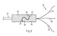
- FIG. 5illustrates a further alternative retainer system that may be used to deploy the spreader of FIGS. 1A-1B .
- FIG. 6is a schematic of a patient's anatomy in the vicinity of the papilla of Vater.
- FIGS. 7A-7Ddescribe method steps for using the spreader of FIGS. 1A-1B .
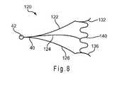
- FIG. 8is an alternative embodiment of the device of FIGS. 1A-1B .
- FIG. 9is a top view illustrating a further alternative embodiment of the device of FIGS. 1A-1B .
- FIG. 10is a top view of the device of FIG. 9 in an assembled state.
- FIG. 11is an elevated side view of the device of FIG. 9 in an assembled state.
- FIG. 12is a side view of apparatus suitable for delivering the device of FIGS. 9-11 .
- FIG. 13is a side view of an alternative apparatus suitable for delivering the device of FIGS. 9-11 .
- FIG. 14is a perspective view of a further alternative embodiment of the device of FIGS. 1A-1B .
- proximalrefers to a direction that is generally towards a physician during a medical procedure
- distalrefers to a direction that is generally towards a target site within a patent's anatomy during a medical procedure.
- the present inventionprovides apparatus suitable for spreading tissue, such as soft tissue in the vicinity of a bodily opening, passageway or cavity, to facilitate access into the opening.
- the apparatuscomprises a spreader that is configured to engage tissue.
- the spreaderhas a constrained delivery state, and an unconstrained state in which a plurality of arms deploy in a radially outward direction to engage tissue and urge the tissue in a direction away from the opening.
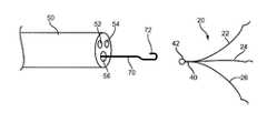
- Spreader 20comprises proximal region 40 and plurality of arms 22 , 24 and 26 extending from proximal region 40 .
- Plurality of arms 22 , 24 and 26may be independently manufactured and then joined together at proximal region 40 , or may be integrally formed during manufacture. While three arms are preferred, it is contemplated that greater or fewer than three arms may be used.
- Plurality of arms 22 , 24 and 26comprise engaging members 32 , 34 and 36 , respectively, which preferably are outwardly bent to facilitate grasping of tissue, as explained in greater detail below.
- Engaging members 32 , 34 and 36may be integrally formed with arms 22 , 24 and 26 , or may comprise sharpened members that are attached to distal regions of one or more arms 22 , 24 and 26 .
- Spreader 20may be made from any suitable resilient material such as stainless steel, nitinol, plastic, and the like.
- arms 22 , 24 and 26may have a cross-sectional shape that is round, square, triangular, pie-shaped, truncated cone, and the like.
- Spreader 20may comprise a retainer system to ensure controlled deployment.
- a first retainersuch as looped region 42 of FIG. 1A , may be integrally formed with proximal region 40 or separately attached thereto.
- the first retainerpreferably is provided with a shape that will complement a shape provided on a second retainer of a delivery/deployment system so that the first and second retainers will matingly join with each other.
- controlled deployment of spreader 20may be achieved.
- engaging member 32comprises a curved region 46 , which is curved in an outward direction as shown.
- engaging member 32 ′comprises one or more barbs 47 , which may be disposed on curved region 46 and adapted to grasp tissue.
- engaging member 32 ′′comprises roughened surface 48 , which may be formed integral to curved region 46 and adapted to grasp tissue. While various embodiments of engaging member 32 have been depicted, engaging members 34 and/or 36 of spreader 20 also may comprise any of the features shown in FIGS. 2A-2C .
- Catheter 50comprises proximal and distal ends and at least one lumen extending therebetween.
- catheter 50has three lumens 52 , 54 and 56 .
- Lumen 56is configured to receive, deliver and facilitate deployment of spreader 20 , as explained in greater detail below.
- the other lumen(s)may be adapted to perform other auxiliary functions, such as receiving a wire guide, an extraction basket adapted to remove a stone, a lithotripsy basket adapted to disintegrate a stone, a balloon catheter adapted to treat a biliary stricture, and/or other devices.
- the other lumen(s)may also be adapted for the passage of fluids, such as the delivery of contrast.
- the distal region of catheter 50also may comprise an external balloon (not shown), which is adapted to be selectively inflated, for example, to treat a biliary stricture.
- Catheter 50preferably comprises a flexible, tubular member that may be formed from one or more semi-rigid polymers.
- catheter 50may be manufactured from polyurethane, polyethylene, tetrafluoroethylene, polytetrafluoroethylene, perfluoalkoxl, fluorinated ethylene propylene, or the like.
- the cathetermay have a length and an outer diameter sufficient to extend through a working channel of conventional endoscope 110 (see FIGS. 7A-7C ).
- catheter 50may comprise an outer diameter of about 6 to 7 French in order to fit within the working channel.
- Catheter 50also may comprise a hydrophilic coating overlying its outer surface. The hydrophilic coating, when applied to the outer surface of catheter 50 , imparts suppleness and kink resistance to the catheter. The hydrophilic coating also may provide a lubricated surface to facilitate movement through the working channel of endoscope 110 .
- the first retainer of the retainer systemis in the form of a looped region 42 at proximal region 40 of spreader 20 .
- the second retainer adapted for use with spreader 20is in the form of wire 70 having proximal and distal ends and hook member 72 disposed at the distal end. Hook member 72 may be integrally formed at the distal end of wire 70 or attached thereto Hook member 72 is adapted to be disposed through looped region 42 of spreader 20 .
- hook member 72is disposed through looped region 42 and arms 22 , 24 and 26 are in a closed position at a location distal to wire 70 . In the closed position, arms 22 , 24 and 26 are adjacent to one another and held in a constrained state within the confines of lumen 56 .
- catheter 50may be retracted proximally with respect to wire 70 and spreader 20 , thereby exposing arms 22 , 24 and 26 and causing the arms to assume a predetermined, radially expanded open position, as shown in FIG. 3 . Further, when catheter 50 is proximally retracted past hook member 72 , the coupling junction where looped region 42 is coupled to hook member 72 is exposed, allowing spreader 20 to be released from wire 70 .
- the second retainercomprises rod 80 having proximal and distal ends and bore 85 disposed at least partially through rod 80 near the distal end.
- Rod 80is configured to be disposed within lumen 56 and is adapted for longitudinal movement therein.
- Rod 80may comprise any suitable material, such as stainless steel.
- Bore 85is adapted to receive looped region 42 of spreader 20 . More specifically, looped region 42 is sufficiently flexible to allow lateral compression so as to fit in bore 85 . Bore 85 may extend partially or completely through rod 80 , and preferably is angled to accommodate looped region 42 , as shown in FIG. 4 . In a preferred embodiment, rod 80 comprises reduced diameter region 86 , which may be formed distal to bore 85 and transition into bore 85 , as shown in FIG. 4 . When looped region 42 is disposed within bore 85 , proximal region 40 of spreader 20 is aligned beneath (adjacent to) reduced diameter region 86 , so that the overall radial profile of the apparatus is not increased.
- the overall radial profile of the constrained armsis preferably about the same as the outer diameter of rod 80 . Therefore, the constrained arms do not substantially increase the radial delivery profile of the apparatus.
- catheter 50may be retracted proximally with respect to wire 80 and spreader 20 , thereby exposing arms 22 , 24 and 26 and causing the arms to assume their predetermined, radially expanded open position, as shown in FIG. 4 . Further, when catheter 50 is proximally retracted past bore 85 , the coupling junction where looped region 42 is coupled to rod 80 is exposed, allowing spreader 20 to be released from rod 80 .
- First retainer 95is operably attached to arms 22 , 24 and 26 of spreader 20 .
- a proximal end of second retainer 90is attached to operating wire 91 , as shown in FIG. 5 .
- First retainer 95 and second retainer 90preferably are cylindrical in cross-sectional shape and have substantially identical outer diameters when mating, as described below.
- First retainer 95comprises partially rounded notch 97 formed therein, and has rounded knob 96 formed proximal to notch 97 .
- second retainer 90comprises partially rounded notch 93 formed therein, and has rounded knob 92 disposed distal to notch 93 .
- rounded knob 92is aligned with notch 97
- rounded knob 96is aligned with notch 93 , as shown in FIG. 5 , thereby securing first retainer 95 to second retainer 90 .
- the first and second retainersare matingly held together when disposed within the confines of catheter lumen 56 , thereby inhibiting movement of the retainers with respect to each other.
- FIGS. 3-5illustrate two exemplary retaining systems that may be used to deliver spreader 20
- many other retaining systemsmay be provided.
- the first and second retainersmay be provided in accordance with any of the retainer mechanisms described in U.S. patent application Ser. No. 11/807,827, filed May 30, 2007, which is hereby incorporated by reference in its entirety.
- spreader 20may be used to spread tissue in the vicinity of a bodily opening to facilitate access into the opening.
- FIGS. 6-7Done exemplary use of spreader 20 is described, whereby spreader 20 facilitates access into the common bile duct via the papilla of Vater during an ERCP procedure.
- the pertinent anatomydepicts common bile duct B leading from liver L into duodenum D.
- Bile duct Bjoins with pancreatic duct P just before papilla of Vater 105 , as shown in FIG. 6 .
- Papilla of Vater 105is a small opening in duodenum D that drains the secretions from bile duct B and pancreatic duct P.
- Stomach Salso empties into duodenum D, as shown in FIG. 6 .
- endoscope 110is inserted into a patient's mouth, through the esophagus, through stomach S, and into duodenum D, as schematically shown in FIG. 6 .
- endoscope 110is a side-viewing endoscope.
- the distal end of endoscope 110is positioned in the vicinity of papilla of Vater 105 .
- Papilla of Vater 105may be located by visualizing the pancreas (not shown), and then tracing bile duct B and/or pancreatic duct P to the wall of duodenum D and papilla of Vater 105 .
- bile duct BIt may be difficult to gain and/or maintain access to bile duct B during an ERCP procedure for various reasons.
- accessing the small opening in papilla of Vater 105may be troublesome.
- the papillar openingmay be fully or partially covered by soft tissue T, as shown in FIG. 7A .
- endoscope 110has been maneuvered into a patient's duodenum D and positioned in the vicinity of papilla of Vater 105 , as explained above.
- Catheter 50is advanced through a working lumen (not shown) of endoscope 110 and is positioned adjacent to papilla of Vater 105 , as shown in FIG. 7A .
- spreader 20preferably is pre-loaded into lumen 56 of catheter 50 .
- Lumen 56constrains arms 22 , 24 and 26 in a closed position such that the arms are adjacent to one another.
- spreader 20is adapted to be deployed in a controlled manner using a retainer system comprising first and second retainers.
- the first retainermay comprise looped region 42 at the proximal region of spreader 20
- the second retainermay comprise wire 70 having hook member 72 ( FIG. 3 ), or may comprise rod 80 having bore 85 ( FIG. 4 ), or another retaining means.
- the first and second retainersare coupled together to secure spreader 20 within lumen 56 .
- catheter 50is retracted proximally with respect to spreader 20 so that engaging members 32 , 34 and 36 of the arms of the spreader are exposed and no longer radially constrained.
- engaging members 32 , 34 and 36grasp tissue T in the vicinity of papilla of Vater 105 and urge tissue T in a radial direction away from the papillar opening, as depicted in FIG. 7B .
- Further retraction of catheter 50causes the distal ends of arms 22 , 24 and 26 to spread apart from one another.
- lumen 56is aligned with papilla of Vater 105 so that when arms 22 , 24 and 26 expand radially outward, they expand away from the papillar opening.
- catheter 50may be further retracted with respect to spreader 20 to expose the coupling junction between the first and second retainers.
- catheter 50is retracted proximal to hook member 72 , allowing looped region 42 of spreader 20 to be released from wire 70 .
- catheter 50is retracted proximal to bore 85 , allowing looped region 42 of spreader 20 to be released from rod 80 . Therefore, spreader 20 is left securely in place in front of papilla of Vater 105 .
- wire guide 90may be advanced distally between one or more arms 22 , 24 and 26 of spreader 20 and guided into bile duct B.
- Wire guide 90may be advanced through a dedicated wire guide lumen of catheter 50 , such as lumen 52 of FIG. 3 .
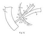
- catheter 50may be advanced distally over wire guide 90 , between one or more arms 22 , 24 and 26 of spreader 20 , and into bile duct B, as shown in FIG. 7C (in this illustration, it should be noted that arm 26 is obscured by catheter 50 ).
- the arms of spreader 20hold tissue T in a spread position away from papilla of Vater 105 , it may be easier for endoscope 110 to view the papillar opening. Therefore, it may be easier to cannulate papilla of Vater 105 and achieve access into bile duct B. Importantly, the likelihood of entering and damaging pancreatic duct P may be reduced.
- one or more proceduresmay be performed while catheter 50 is disposed within bile duct B.
- an extraction basket(not shown) may be advanced through catheter lumen 54 and used to remove a gallstone lodged within bile duct B.
- catheter 50may be used to treat a biliary stricture, for example, by disposing an inflation balloon on an exterior surface of catheter 50 .
- a lithotripsy probe or other devicemay be inserted into bile duct B via the papillar opening once access is achieved and maintained.
- spreader 20may be left inside the patient or removed.
- a reverse sequence of one or more steps from 7 A- 7 Bmay be used.
- the hook member 72 on the distal end of wire 70may be advanced and engaged with the looped region 42 of spreader 20 .
- Catheter 50is then advanced distally such that lumen 56 is advanced over proximal region 40 of spreader 20 to collapse the arms 22 , 24 and 26 together, thereby allowing spreader 20 to be removed.
- a forceps or other grasping devicecan be deployed through a separate sheath, the forceps being used to grasp and pull the spreader 20 into the sheath.
- the catheter or sheathis advanced over proximal region 40 and then over arms 22 , 24 and 26 to cause the arms to move radially inward and disengage tissue T.
- the advancement of the catheter or sheathwill cause arms 22 , 24 and 26 to be radially constrained therein.
- spreader 20may be retracted proximally within the catheter or sheath by engaging looped region 42 .
- spreader 20may be left inside the patient, as shown in FIG. 7D .
- Spreader 20may be configured to detach from tissue T over a period of time and may pass naturally through the patient.
- Spreader 20may also comprise a biodegradable material that will eventually dissolve and pass harmlessly out of the body. If desired, spreader 20 may be designed to permanently engage tissue T, in which case the spreader will be left inside the patient.
- spreader 20may be removable when made from a shape memory material, whereby the spreader can assume a relaxed configuration in which it readily disengages from tissue upon application of a certain cold or hot medium.
- a shape memory materialmay undergo a substantially reversible phase transformation that allows it to “remember” and return to a previous shape or configuration.
- a transformation between an austenitic phase and a martensitic phasemay occur by cooling and/or heating (shape memory effect) or by isothermally applying and/or removing stress (superelastic effect).
- Austeniteis characteristically the stronger phase and martensite is the more easily deformable phase.
- a nickel-titanium alloy having an initial configuration in the austenitic phasemay be cooled below a transformation temperature (M f ) to the martensitic phase and then deformed to a second configuration.
- M ftransformation temperature
- a ftransformation temperature
- the materialmay spontaneously return to its initial configuration.
- the memory effectis one-way, which means that the spontaneous change from one configuration to another occurs only upon heating.
- a second, predetermined temperaturemay be applied to spreader 20 , e.g., by injecting fluid through catheter 50 or by direct contact of a temperature-inducing element, to cause arms 22 , 24 and 26 to transform to a relaxed state in which they more easily let go of the tissue.
- spreader 20may assume a relatively atraumatic posture so that it can be safely passed through the body.
- biasing member 140may be coupled directly to engaging members 132 and 136 of arms 122 and 126 , respectively. Biasing member 140 also may be coupled directly to arms 122 , 124 and/or 126 at a location proximal of the engaging members. As depicted, biasing member 140 may comprise a cylindrical, zig-zag shaped member having a plurality of substantially straight sections separated by a plurality of bends, although other configurations are possible.
- Biasing member 140may be manufactured using a nickel-titanium alloy and may comprise a reduced profile delivery configuration and a radially expanded spreading configuration. In the expanded state, biasing member 140 may provide a larger tissue engaging area compared to the use of arms 22 , 24 and 26 by themselves, and may facilitate entry into bodily openings that are otherwise difficult to access.
- spreader 20may be used to help spread tissue to gain access to many other constrained bodily openings, passageways, ducts or cavities.
- spreader 20may be used to open an annular passageway itself, as opposed to tissue in the vicinity of the passageway.
- arms 22 , 24 and 26may be designed to have a stronger radial force, for example, to spread open a sphincter, such as the sphincter of Oddi or another passageway.
- spreader 200is formed from first and second portions 202 and 204 .
- First portion 202comprises first and second arms 212 and 213 , which are separated by central region 211 .
- second portion 204comprises third and fourth arms 216 and 217 , which are separated by central region 215 , as shown in FIG. 9 .
- the four arms 212 , 213 , 216 and 217may be provided as generally explained above with respect to the arms 22 , 24 and 26 of spreader 20 .
- each of the four arms 212 , 213 , 216 and 217may comprise a curvature and/or an engaging member bent outwardly and adapted to grasp tissue.
- central regions 211 and 215may comprise a wire or other suitable material bent into a substantially circumferential shape spanning between 180-360 degrees.
- central regions 211 and 215may comprise a wire forming a 360 degree loop, U-shape, or the like, for purposes described below.
- first and second portions 202 and 204are coupled together.
- central regions 211 and 215may be aligned and then coupled together using an adhesive 220 .
- the four arms 212 , 213 , 216 and 217 of spreader 200preferably extend in opposing circumferential directions to facilitate spreading tissue, as explained above.
- central regions 211 and 215may be braided or twisted together.
- the overlapping portionsmay form a loop, U-shape, or the like.
- a sleevemay be disposed over central regions 211 and 215 to help secure first and second portions 202 and 204 together.
- Catheter 240preferably comprises proximal and distal ends and at least one lumen 244 extending therebetween.
- Catheter 240further comprises an exterior surface having at least one ridge 242 formed therein, as shown in FIG. 12 .
- spreader 200is delivered substantially from the outside of catheter 240 , as opposed to through an interior lumen.
- overlapping central regions 211 and 215may be disposed around a perimeter of catheter 240 using a frictional fit, or by being held into place within ridge 242 , or using an additional securing mechanism.
- At least one filament 250is employed to hold the four arms 212 , 213 , 216 and 217 of spreader 200 together in the delivery state.
- Filament 250preferably extends through lumen 244 and spans the entire length of catheter 240 .
- a splittable sheathis employed to hold the four arms 212 , 213 , 216 and 217 of spreader 200 together in the delivery state.
- Splittable sheath 260has a proximal end coupled to wire 264 , which extends longitudinally through lumen 244 .
- Splittable sheath 260further comprises at least one tear line 262 .
- wire 264is retracted proximally within lumen 244 , thereby causing the at least one tear line 262 to tear apart and release spreader 200 .
- splittable sheath 260may be withdrawn into lumen 244 , while arms 212 , 213 , 216 and 217 are released and radially expand to engage tissue, as depicted in FIGS. 10-11 above.
- spreader 300is similar to spreader 200 of FIGS. 9-11 , with a main exception that it is manufactured from a single component instead of two separate components that are coupled together.
- Spreader 300comprises a base portion 302 having a circular configuration, and a plurality of integral arms 303 - 306 extending therefrom, as shown in FIG. 14 .
- Base portion 302may be sized to be fit over an outer surface of catheter 240 , for example, using a frictional fit, or by being placed in ridge 242 .
- spreader 300may be configured for delivery internally though a lumen of a catheter, as generally described above with respect to FIGS. 3-4 .
Landscapes
- Health & Medical Sciences (AREA)
- Life Sciences & Earth Sciences (AREA)
- Surgery (AREA)
- Heart & Thoracic Surgery (AREA)
- Engineering & Computer Science (AREA)
- Biomedical Technology (AREA)
- Nuclear Medicine, Radiotherapy & Molecular Imaging (AREA)
- Medical Informatics (AREA)
- Molecular Biology (AREA)
- Animal Behavior & Ethology (AREA)
- General Health & Medical Sciences (AREA)
- Public Health (AREA)
- Veterinary Medicine (AREA)
- Surgical Instruments (AREA)
- Media Introduction/Drainage Providing Device (AREA)
Abstract
Description
Claims (15)
Priority Applications (1)
| Application Number | Priority Date | Filing Date | Title |
|---|---|---|---|
| US11/776,212US8425412B2 (en) | 2006-07-14 | 2007-07-11 | Papilla spreader |
Applications Claiming Priority (2)
| Application Number | Priority Date | Filing Date | Title |
|---|---|---|---|
| US83083506P | 2006-07-14 | 2006-07-14 | |
| US11/776,212US8425412B2 (en) | 2006-07-14 | 2007-07-11 | Papilla spreader |
Publications (2)
| Publication Number | Publication Date |
|---|---|
| US20080015416A1 US20080015416A1 (en) | 2008-01-17 |
| US8425412B2true US8425412B2 (en) | 2013-04-23 |
Family
ID=38857911
Family Applications (1)
| Application Number | Title | Priority Date | Filing Date |
|---|---|---|---|
| US11/776,212Active2031-11-28US8425412B2 (en) | 2006-07-14 | 2007-07-11 | Papilla spreader |
Country Status (7)
| Country | Link |
|---|---|
| US (1) | US8425412B2 (en) |
| EP (1) | EP2040788B1 (en) |
| JP (1) | JP2009543660A (en) |
| AT (1) | ATE547143T1 (en) |
| AU (1) | AU2007272981B2 (en) |
| CA (1) | CA2659591C (en) |
| WO (1) | WO2008008384A2 (en) |
Cited By (10)
| Publication number | Priority date | Publication date | Assignee | Title |
|---|---|---|---|---|
| US9445801B2 (en) | 2013-03-15 | 2016-09-20 | Cook Medical Technologies Llc | Medical device with selective rigidity |
| US10524813B2 (en) | 2015-04-19 | 2020-01-07 | Bam Medical Ltd. | Frenulum spreader |
| US10925616B2 (en) | 2017-03-21 | 2021-02-23 | Teleflex Medical Incorporated | Clip applier with replaceable tips |
| US11160559B2 (en) | 2017-03-21 | 2021-11-02 | Teleflex Medical Incorporated | Clip applier with stabilizing member |
| US11266408B2 (en) | 2017-03-21 | 2022-03-08 | Teleflex Medical Incorporated | Clip applier having stabilizing member |
| US11534177B2 (en) | 2017-03-21 | 2022-12-27 | Teleflex Medical Incorporated | Flexible stabilizing member for a clip applier |
| US11607227B2 (en) | 2017-03-21 | 2023-03-21 | Teleflex Medical Incorporated | Surgical clip and clip applier |
| US12023041B2 (en) | 2017-03-21 | 2024-07-02 | Teleflex Medical Incorporated | Clip applier |
| US12279774B2 (en) | 2018-09-26 | 2025-04-22 | Teleflex Medical Incorporated | Clip applier with stabilizing member |
| US12318094B2 (en) | 2019-09-26 | 2025-06-03 | Teleflex Medical Incorporated | Clip applier |
Families Citing this family (7)
| Publication number | Priority date | Publication date | Assignee | Title |
|---|---|---|---|---|
| US9610072B2 (en)* | 2009-11-02 | 2017-04-04 | Apx Opthalmology Ltd. | Iris retractor |
| US20110178513A1 (en)* | 2010-01-21 | 2011-07-21 | CreamOptee Industries Inc. | Method and device for internal tissue removal |
| US9017246B2 (en)* | 2010-11-19 | 2015-04-28 | Boston Scientific Scimed, Inc. | Biliary catheter systems including stabilizing members |
| US9655754B2 (en)* | 2013-01-10 | 2017-05-23 | Trivascular, Inc. | Systems and methods for guidewire crossover for bifurcated prostheses |
| US20140336464A1 (en)* | 2013-05-08 | 2014-11-13 | Boston Scientific Scimed, Inc. | Expansion devices and methods of use thereof |
| AU2015277089B2 (en)* | 2014-06-18 | 2017-11-02 | Boston Scientific Scimed, Inc. | Biliary stent |
| CN110384569A (en)* | 2019-07-24 | 2019-10-29 | 苏州大学附属第一医院 | A kind of preparation method of recoverability obstruction of bile duct rat model |
Citations (103)
| Publication number | Priority date | Publication date | Assignee | Title |
|---|---|---|---|---|
| US943263A (en) | 1909-05-06 | 1909-12-14 | Ernest Moraweck | Surgical forceps. |
| US1510416A (en) | 1922-04-15 | 1924-09-30 | Pietz Frederick | Forceps |
| US1578800A (en) | 1926-01-19 | 1926-03-30 | Carl F Brandenberger | Grabbing tool |
| US2113246A (en) | 1937-05-17 | 1938-04-05 | Wappler Frederick Charles | Endoscopic forceps |
| US2384697A (en) | 1944-10-18 | 1945-09-11 | Riccardi Peter | Umbilical clip |
| US2968041A (en) | 1958-09-25 | 1961-01-17 | John F Skold | Applicator for surgical clamps |
| US3378010A (en) | 1965-07-28 | 1968-04-16 | Coldling | Surgical clip with means for releasing the clamping pressure |
| US3518993A (en) | 1967-05-01 | 1970-07-07 | American Hospital Supply Corp | Surgical clip applicator |
| US3616497A (en) | 1970-06-24 | 1971-11-02 | Vincent J Esposito Jr | Integral clamping instruments for medical and surgical applications |
| US3777538A (en) | 1972-03-15 | 1973-12-11 | Weck & Co Edward | Surgical clip applicator |
| DE2330182A1 (en) | 1973-06-14 | 1975-01-02 | Wolf Gmbh Richard | PLIERS FOR SETTING TANTALUM CLIPS |
| US3882854A (en) | 1973-08-23 | 1975-05-13 | Research Corp | Surgical clip and applicator |
| US3958576A (en) | 1973-11-14 | 1976-05-25 | Olympus Optical Co., Ltd. | Surgical instrument for clipping any affected portion of a body cavity |
| US4038987A (en) | 1974-02-08 | 1977-08-02 | Olympus Optical Co., Ltd. | Forceps device for endoscope |
| US4046149A (en) | 1975-01-31 | 1977-09-06 | Olympus Optical Co., Ltd. | Instrument for removing a foreign substance from the body cavity of human being |
| US4169476A (en) | 1977-08-12 | 1979-10-02 | Wolf Medical Instruments Corporation | Applicator for surgical clip |
| US4215871A (en) | 1979-03-05 | 1980-08-05 | Vargus Ltd. | Hand held collet |
| US4367746A (en) | 1979-12-11 | 1983-01-11 | Derechinsky Victor E | Clip-holder instrument for clipping blood vessels |
| US4394864A (en) | 1981-04-15 | 1983-07-26 | Jeffrey Sandhaus | Apparatus and method for effecting occlusion of the vas deferens |
| US4394861A (en) | 1981-05-11 | 1983-07-26 | Sciortino Lawrence A | Outside air breathing supply system |
| US4446865A (en) | 1981-03-16 | 1984-05-08 | Ethicon, Inc. | Plastic ligating clips |
| US4485817A (en) | 1982-05-28 | 1984-12-04 | United States Surgical Corporation | Surgical stapler apparatus with flexible shaft |
| US4496090A (en) | 1982-03-10 | 1985-01-29 | Crevier Paul H | Surgical stapler |
| US4512345A (en) | 1982-09-30 | 1985-04-23 | United States Surgical Corporation | Surgical clip applying apparatus, and clips and clip train for use therein |
| US4681107A (en) | 1985-12-31 | 1987-07-21 | Kees Surgical Specialty Co. | Device for holding an aneurysm clip |
| US4706668A (en) | 1985-09-16 | 1987-11-17 | B & B Tools | Aneurysm clip pliers |
| US4714075A (en) | 1986-02-10 | 1987-12-22 | Welch Allyn, Inc. | Biopsy channel for endoscope |
| US4735194A (en) | 1987-01-13 | 1988-04-05 | University Patents, Inc. | Flexible endoscopic ligating instrument |
| US4759364A (en) | 1985-09-19 | 1988-07-26 | Richard Wolf Gmbh | Pincers attachment for a surgical handle to be used in endoscopy |
| US4796627A (en) | 1986-08-26 | 1989-01-10 | Tucker Wilson H | Clip applicator and spreadable clips for use therein |
| US4821721A (en) | 1985-01-14 | 1989-04-18 | Thomas J. Fogarty | Apparatus and method for applying hemostatic scalp clips |
| US4835824A (en) | 1988-04-13 | 1989-06-06 | Durham Vaughn L | Medical clamp |
| US4841888A (en) | 1984-09-11 | 1989-06-27 | Mills Timothy N | Sewing machine |
| US4880015A (en) | 1988-06-03 | 1989-11-14 | Nierman David M | Biopsy forceps |
| US4887612A (en) | 1988-04-27 | 1989-12-19 | Esco Precision, Inc. | Endoscopic biopsy forceps |
| US4934364A (en) | 1982-09-30 | 1990-06-19 | United States Surgical Corporation | Surgical clip applying apparatus having fixed jams |
| US4945920A (en) | 1988-03-28 | 1990-08-07 | Cordis Corporation | Torqueable and formable biopsy forceps |
| US4971067A (en) | 1988-05-05 | 1990-11-20 | Lee Bolduc | Biopsy instrument with a disposable cutting blade |
| US4983176A (en) | 1989-03-06 | 1991-01-08 | University Of New Mexico | Deformable plastic surgical clip |
| US5015249A (en) | 1989-12-26 | 1991-05-14 | Nakao Naomi L | Endoscopic stapling device and method |
| US5049153A (en) | 1989-12-26 | 1991-09-17 | Nakao Naomi L | Endoscopic stapling device and method |
| US5062848A (en) | 1990-03-07 | 1991-11-05 | Frazee John G | Hemostatic clip and applicator therefor |
| US5100418A (en) | 1987-05-14 | 1992-03-31 | Inbae Yoon | Suture tie device system and applicator therefor |
| US5112343A (en) | 1991-04-05 | 1992-05-12 | Edward Weck Incorporated | Endoscopic clip appliers |
| US5156609A (en) | 1989-12-26 | 1992-10-20 | Nakao Naomi L | Endoscopic stapling device and method |
| US5222961A (en) | 1989-12-26 | 1993-06-29 | Naomi Nakao | Endoscopic stapling device and related staple |
| US5242456A (en) | 1991-11-21 | 1993-09-07 | Kensey Nash Corporation | Apparatus and methods for clamping tissue and reflecting the same |
| US5300081A (en) | 1992-10-09 | 1994-04-05 | United States Surgical Corporation | Surgical clip applier having clip advancement control |
| US5304183A (en) | 1992-03-23 | 1994-04-19 | Laparomed Corporation | Tethered clamp retractor |
| US5366459A (en) | 1987-05-14 | 1994-11-22 | Inbae Yoon | Surgical clip and clip application procedures |
| US5395381A (en) | 1990-12-13 | 1995-03-07 | United States Surgical Corporation | Apparatus and method for applying latchless surgical clips |
| US5403342A (en)* | 1992-04-23 | 1995-04-04 | United States Surgical Corporation | Articulating endoscopic surgical apparatus |
| US5441509A (en) | 1992-04-28 | 1995-08-15 | Minnesota Mining And Manufacturing Company | Vessel clips |
| US5464416A (en) | 1992-11-10 | 1995-11-07 | Ethicon, Inc. | Ligating clip |
| US5474567A (en) | 1992-09-14 | 1995-12-12 | Ethicon, Inc. | Sterile clips and instrument for their placement |
| US5486185A (en) | 1989-01-30 | 1996-01-23 | Dexide, Inc. | Surgical apparatus |
| US5514148A (en) | 1994-11-04 | 1996-05-07 | Smith, Iii; Ray C. | Surgical clamp and method of use |
| US5527319A (en) | 1992-02-13 | 1996-06-18 | United States Surgical Corporation | Surgical fastener applying instrument for ligating and dividing tissue |
| US5540124A (en) | 1992-06-19 | 1996-07-30 | Srhoj; Edward B. | Adjustable gripping device |
| US5569274A (en) | 1993-02-22 | 1996-10-29 | Heartport, Inc. | Endoscopic vascular clamping system and method |
| DE19534320C1 (en) | 1995-09-15 | 1997-02-27 | Aesculap Ag | Instrument fitting and removing surgical clips |
| US5609601A (en)* | 1994-09-23 | 1997-03-11 | United States Surgical Corporation | Endoscopic surgical apparatus with rotation lock |
| US5634932A (en) | 1995-10-10 | 1997-06-03 | Industrial & Scientific Designs, Ltd. | Cantilever aneurysm clip system |
| US5695504A (en) | 1995-02-24 | 1997-12-09 | Heartport, Inc. | Devices and methods for performing a vascular anastomosis |
| US5700271A (en) | 1995-10-20 | 1997-12-23 | United States Surgical Corporation | Apparatus for applying surgical clips |
| US5733329A (en) | 1996-12-30 | 1998-03-31 | Target Therapeutics, Inc. | Vaso-occlusive coil with conical end |
| US5766189A (en) | 1996-02-29 | 1998-06-16 | Olympus Optical Co., Ltd. | Clip device |
| US5766184A (en) | 1994-11-02 | 1998-06-16 | Olympus Optical Co., Ltd. | Endoscopic treatment tool |
| US5782747A (en) | 1996-04-22 | 1998-07-21 | Zimmon Science Corporation | Spring based multi-purpose medical instrument |
| DE29811510U1 (en) | 1998-06-27 | 1998-10-08 | Tenckhoff, Dirk, 36100 Petersberg | Device for handling clips, in particular for microsurgery |
| US5895394A (en) | 1996-09-24 | 1999-04-20 | Aesculap Ag & Co. Kg | Surgical Applicator for U-shaped clips |
| US5980534A (en) | 1998-10-07 | 1999-11-09 | Gimpelson; Richard J. | Cervical clamp |
| US5989268A (en) | 1997-10-28 | 1999-11-23 | Boston Scientific Corporation | Endoscopic hemostatic clipping device |
| US6001110A (en) | 1997-06-20 | 1999-12-14 | Boston Scientific Corporation | Hemostatic clips |
| USRE36720E (en) | 1990-12-13 | 2000-05-30 | United States Surgical Corporation | Apparatus and method for applying latchless surgical clips |
| DE10011292A1 (en) | 1999-03-08 | 2000-09-14 | Asahi Optical Co Ltd | Clamp fastening arrangement for endoscope; has clamp with control wire and clamp fastening arrangement releasably connected to control element to secure clamp |
| US6139555A (en) | 1996-04-19 | 2000-10-31 | Applied Medical Resources Corporation | Grasping clip applier |
| US6155968A (en) | 1998-07-23 | 2000-12-05 | Wilk; Peter J. | Method and device for improving cardiac function |
| US6167605B1 (en) | 1997-09-12 | 2001-01-02 | Advanced Cardiovascular Systems, Inc. | Collet type crimping tool |
| US6228023B1 (en)* | 1999-02-17 | 2001-05-08 | Abiomed, Inc. | Tissue pick and method for use in minimally invasive surgical procedures |
| DE19955614C1 (en) | 1999-11-19 | 2001-07-26 | Karlsruhe Forschzent | Endoscopically-inserted falloposcope for examining ovaries and fallopian tubes has longitudinal slits at instrument end of Bowden cable providing expansion arms for widening out fallopian tube |
| US6267776B1 (en) | 1999-05-03 | 2001-07-31 | O'connell Paul T. | Vena cava filter and method for treating pulmonary embolism |
| US20010049497A1 (en) | 2000-03-24 | 2001-12-06 | Kalloo Anthony Nicolas | Methods and devices for diagnostic and therapeutic interventions in the peritoneal cavity |
| US6350269B1 (en) | 1999-03-01 | 2002-02-26 | Apollo Camera, L.L.C. | Ligation clip and clip applier |
| US6352541B1 (en) | 1997-11-26 | 2002-03-05 | Aesculap Ag & Co. Kg | Magazine for a surgical clip applicator |
| US20020032462A1 (en) | 1998-06-10 | 2002-03-14 | Russell A. Houser | Thermal securing anastomosis systems |
| US20020045909A1 (en) | 2000-10-16 | 2002-04-18 | Olympus Optical Co., Ltd. | Physiological tissue clipping apparatus, clipping method and clip unit mounting method |
| US20020055750A1 (en) | 1999-11-18 | 2002-05-09 | Russell F. Durgin | Apparatus and method for compressing body tissue |
| US20020062130A1 (en) | 1999-11-18 | 2002-05-23 | Jugenheimer Kristen A. | Apparatus and method for compressing body tissue |
| US20020128667A1 (en) | 2001-03-07 | 2002-09-12 | Olympus Optical Co., Ltd. | Apparatus for ligating living tissues |
| US20020133178A1 (en) | 2001-03-14 | 2002-09-19 | Olympus Optical Co., Ltd. | Apparatus for ligating living tissues |
| US20020138085A1 (en) | 2001-03-22 | 2002-09-26 | Olympus Optical Co., Ltd | Multifunctional surgical operation device |
| US20020138083A1 (en) | 2001-03-26 | 2002-09-26 | Olympus Optical Co., Ltd. | Apparatus for ligating living tissues |
| US6464710B1 (en) | 1995-03-06 | 2002-10-15 | Cook Urological Incorporated | Releasable, surgical clamp |
| US20020151916A1 (en) | 2001-02-05 | 2002-10-17 | Junichi Muramatsu | Apparatus for ligating living tissues |
| US20020173805A1 (en) | 2001-02-06 | 2002-11-21 | Kiyotaka Matsuno | Clipping device |
| US20030069593A1 (en) | 2001-08-31 | 2003-04-10 | Tremulis William S. | Method and apparatus for valve repair |
| US20030069592A1 (en) | 2001-10-05 | 2003-04-10 | Scimed Life Systems, Inc. | Device and method for through the scope endoscopic hemostatic clipping |
| US20040092978A1 (en) | 2002-04-15 | 2004-05-13 | Surti Vihar C. | Clip device |
| US20050033312A1 (en) | 2003-07-02 | 2005-02-10 | Olympus Corporation | Ligation apparatus |
| US20050143767A1 (en) | 2002-08-21 | 2005-06-30 | Olympus Corporation | Living tissue ligation device |
| EP1604614A1 (en) | 2003-03-17 | 2005-12-14 | Sumitomo Bakelite Co., Ltd. | Clip and clipping instrument for biological tissues |
| EP1325717B1 (en) | 2002-01-08 | 2006-07-05 | Cordis Corporation | Stent graft with branch leg |
Family Cites Families (8)
| Publication number | Priority date | Publication date | Assignee | Title |
|---|---|---|---|---|
| US4655219A (en)* | 1983-07-22 | 1987-04-07 | American Hospital Supply Corporation | Multicomponent flexible grasping device |
| US4909789A (en)* | 1986-03-28 | 1990-03-20 | Olympus Optical Co., Ltd. | Observation assisting forceps |
| JPH0829164B2 (en)* | 1986-12-25 | 1996-03-27 | オリンパス光学工業株式会社 | Biological duct dilator |
| US5488017A (en)* | 1989-04-14 | 1996-01-30 | General Electric Company | Fibert reinforced ceramic matrix composite member |
| JPH065601U (en)* | 1992-06-30 | 1994-01-25 | オリンパス光学工業株式会社 | Introduction aid for endoscopes |
| US5488185A (en)* | 1993-09-30 | 1996-01-30 | The Boc Group, Inc. | Process for the production of ethanol and isopropanol |
| JP3742542B2 (en)* | 2000-03-10 | 2006-02-08 | ペンタックス株式会社 | Endoscope foreign matter collection tool |
| US6958074B2 (en)* | 2002-01-07 | 2005-10-25 | Cordis Corporation | Releasable and retrievable vascular filter system |
- 2007
- 2007-07-11ATAT07810342Tpatent/ATE547143T1/enactive
- 2007-07-11AUAU2007272981Apatent/AU2007272981B2/ennot_activeCeased
- 2007-07-11JPJP2009520764Apatent/JP2009543660A/enactivePending
- 2007-07-11WOPCT/US2007/015803patent/WO2008008384A2/enactiveApplication Filing
- 2007-07-11CACA2659591Apatent/CA2659591C/enactiveActive
- 2007-07-11USUS11/776,212patent/US8425412B2/enactiveActive
- 2007-07-11EPEP07810342Apatent/EP2040788B1/ennot_activeNot-in-force
Patent Citations (111)
| Publication number | Priority date | Publication date | Assignee | Title |
|---|---|---|---|---|
| US943263A (en) | 1909-05-06 | 1909-12-14 | Ernest Moraweck | Surgical forceps. |
| US1510416A (en) | 1922-04-15 | 1924-09-30 | Pietz Frederick | Forceps |
| US1578800A (en) | 1926-01-19 | 1926-03-30 | Carl F Brandenberger | Grabbing tool |
| US2113246A (en) | 1937-05-17 | 1938-04-05 | Wappler Frederick Charles | Endoscopic forceps |
| US2384697A (en) | 1944-10-18 | 1945-09-11 | Riccardi Peter | Umbilical clip |
| US2968041A (en) | 1958-09-25 | 1961-01-17 | John F Skold | Applicator for surgical clamps |
| US3378010A (en) | 1965-07-28 | 1968-04-16 | Coldling | Surgical clip with means for releasing the clamping pressure |
| US3518993A (en) | 1967-05-01 | 1970-07-07 | American Hospital Supply Corp | Surgical clip applicator |
| US3616497A (en) | 1970-06-24 | 1971-11-02 | Vincent J Esposito Jr | Integral clamping instruments for medical and surgical applications |
| US3777538A (en) | 1972-03-15 | 1973-12-11 | Weck & Co Edward | Surgical clip applicator |
| DE2330182A1 (en) | 1973-06-14 | 1975-01-02 | Wolf Gmbh Richard | PLIERS FOR SETTING TANTALUM CLIPS |
| US3882854A (en) | 1973-08-23 | 1975-05-13 | Research Corp | Surgical clip and applicator |
| US3958576A (en) | 1973-11-14 | 1976-05-25 | Olympus Optical Co., Ltd. | Surgical instrument for clipping any affected portion of a body cavity |
| US4038987A (en) | 1974-02-08 | 1977-08-02 | Olympus Optical Co., Ltd. | Forceps device for endoscope |
| US4046149A (en) | 1975-01-31 | 1977-09-06 | Olympus Optical Co., Ltd. | Instrument for removing a foreign substance from the body cavity of human being |
| US4169476A (en) | 1977-08-12 | 1979-10-02 | Wolf Medical Instruments Corporation | Applicator for surgical clip |
| US4215871A (en) | 1979-03-05 | 1980-08-05 | Vargus Ltd. | Hand held collet |
| US4367746A (en) | 1979-12-11 | 1983-01-11 | Derechinsky Victor E | Clip-holder instrument for clipping blood vessels |
| US4446865A (en) | 1981-03-16 | 1984-05-08 | Ethicon, Inc. | Plastic ligating clips |
| US4394864A (en) | 1981-04-15 | 1983-07-26 | Jeffrey Sandhaus | Apparatus and method for effecting occlusion of the vas deferens |
| US4394861A (en) | 1981-05-11 | 1983-07-26 | Sciortino Lawrence A | Outside air breathing supply system |
| US4496090A (en) | 1982-03-10 | 1985-01-29 | Crevier Paul H | Surgical stapler |
| US4485817A (en) | 1982-05-28 | 1984-12-04 | United States Surgical Corporation | Surgical stapler apparatus with flexible shaft |
| US4512345A (en) | 1982-09-30 | 1985-04-23 | United States Surgical Corporation | Surgical clip applying apparatus, and clips and clip train for use therein |
| US4934364A (en) | 1982-09-30 | 1990-06-19 | United States Surgical Corporation | Surgical clip applying apparatus having fixed jams |
| US4841888A (en) | 1984-09-11 | 1989-06-27 | Mills Timothy N | Sewing machine |
| US4821721A (en) | 1985-01-14 | 1989-04-18 | Thomas J. Fogarty | Apparatus and method for applying hemostatic scalp clips |
| US4706668A (en) | 1985-09-16 | 1987-11-17 | B & B Tools | Aneurysm clip pliers |
| US4759364A (en) | 1985-09-19 | 1988-07-26 | Richard Wolf Gmbh | Pincers attachment for a surgical handle to be used in endoscopy |
| US4681107A (en) | 1985-12-31 | 1987-07-21 | Kees Surgical Specialty Co. | Device for holding an aneurysm clip |
| US4714075A (en) | 1986-02-10 | 1987-12-22 | Welch Allyn, Inc. | Biopsy channel for endoscope |
| US4796627A (en) | 1986-08-26 | 1989-01-10 | Tucker Wilson H | Clip applicator and spreadable clips for use therein |
| US4735194A (en) | 1987-01-13 | 1988-04-05 | University Patents, Inc. | Flexible endoscopic ligating instrument |
| US4735194C1 (en) | 1987-01-13 | 2001-05-08 | Dept Of Veterans Affairs The U | Flexile endoscopic ligating instrument |
| US5445167A (en) | 1987-05-14 | 1995-08-29 | Yoon; Inbae | Methods of applying surgical chips and suture tie devices to bodily tissue during endoscopic procedures |
| US5366459A (en) | 1987-05-14 | 1994-11-22 | Inbae Yoon | Surgical clip and clip application procedures |
| US5100418A (en) | 1987-05-14 | 1992-03-31 | Inbae Yoon | Suture tie device system and applicator therefor |
| US4945920A (en) | 1988-03-28 | 1990-08-07 | Cordis Corporation | Torqueable and formable biopsy forceps |
| US4835824A (en) | 1988-04-13 | 1989-06-06 | Durham Vaughn L | Medical clamp |
| US4887612A (en) | 1988-04-27 | 1989-12-19 | Esco Precision, Inc. | Endoscopic biopsy forceps |
| US4971067A (en) | 1988-05-05 | 1990-11-20 | Lee Bolduc | Biopsy instrument with a disposable cutting blade |
| US4880015A (en) | 1988-06-03 | 1989-11-14 | Nierman David M | Biopsy forceps |
| US5486185A (en) | 1989-01-30 | 1996-01-23 | Dexide, Inc. | Surgical apparatus |
| US4983176A (en) | 1989-03-06 | 1991-01-08 | University Of New Mexico | Deformable plastic surgical clip |
| US5156609A (en) | 1989-12-26 | 1992-10-20 | Nakao Naomi L | Endoscopic stapling device and method |
| US5222961A (en) | 1989-12-26 | 1993-06-29 | Naomi Nakao | Endoscopic stapling device and related staple |
| US5015249A (en) | 1989-12-26 | 1991-05-14 | Nakao Naomi L | Endoscopic stapling device and method |
| US5049153A (en) | 1989-12-26 | 1991-09-17 | Nakao Naomi L | Endoscopic stapling device and method |
| US5062848A (en) | 1990-03-07 | 1991-11-05 | Frazee John G | Hemostatic clip and applicator therefor |
| USRE36720E (en) | 1990-12-13 | 2000-05-30 | United States Surgical Corporation | Apparatus and method for applying latchless surgical clips |
| US5395381A (en) | 1990-12-13 | 1995-03-07 | United States Surgical Corporation | Apparatus and method for applying latchless surgical clips |
| US5112343A (en) | 1991-04-05 | 1992-05-12 | Edward Weck Incorporated | Endoscopic clip appliers |
| US5242456A (en) | 1991-11-21 | 1993-09-07 | Kensey Nash Corporation | Apparatus and methods for clamping tissue and reflecting the same |
| US5527319A (en) | 1992-02-13 | 1996-06-18 | United States Surgical Corporation | Surgical fastener applying instrument for ligating and dividing tissue |
| US5304183A (en) | 1992-03-23 | 1994-04-19 | Laparomed Corporation | Tethered clamp retractor |
| US5403342A (en)* | 1992-04-23 | 1995-04-04 | United States Surgical Corporation | Articulating endoscopic surgical apparatus |
| US5441509A (en) | 1992-04-28 | 1995-08-15 | Minnesota Mining And Manufacturing Company | Vessel clips |
| US5540124A (en) | 1992-06-19 | 1996-07-30 | Srhoj; Edward B. | Adjustable gripping device |
| US5474567A (en) | 1992-09-14 | 1995-12-12 | Ethicon, Inc. | Sterile clips and instrument for their placement |
| US5601574A (en) | 1992-09-14 | 1997-02-11 | Ethicon, Inc. | Sterile clips and instrument for their placement |
| US5300081A (en) | 1992-10-09 | 1994-04-05 | United States Surgical Corporation | Surgical clip applier having clip advancement control |
| US5464416A (en) | 1992-11-10 | 1995-11-07 | Ethicon, Inc. | Ligating clip |
| US5569274A (en) | 1993-02-22 | 1996-10-29 | Heartport, Inc. | Endoscopic vascular clamping system and method |
| US5609601A (en)* | 1994-09-23 | 1997-03-11 | United States Surgical Corporation | Endoscopic surgical apparatus with rotation lock |
| US5766184A (en) | 1994-11-02 | 1998-06-16 | Olympus Optical Co., Ltd. | Endoscopic treatment tool |
| EP0738501B1 (en) | 1994-11-02 | 2000-05-24 | Olympus Optical Co., Ltd. | Endoscope operative instrument |
| US5514148A (en) | 1994-11-04 | 1996-05-07 | Smith, Iii; Ray C. | Surgical clamp and method of use |
| US5695504A (en) | 1995-02-24 | 1997-12-09 | Heartport, Inc. | Devices and methods for performing a vascular anastomosis |
| US6464710B1 (en) | 1995-03-06 | 2002-10-15 | Cook Urological Incorporated | Releasable, surgical clamp |
| DE19534320C1 (en) | 1995-09-15 | 1997-02-27 | Aesculap Ag | Instrument fitting and removing surgical clips |
| US5634932A (en) | 1995-10-10 | 1997-06-03 | Industrial & Scientific Designs, Ltd. | Cantilever aneurysm clip system |
| US5700271A (en) | 1995-10-20 | 1997-12-23 | United States Surgical Corporation | Apparatus for applying surgical clips |
| US5766189A (en) | 1996-02-29 | 1998-06-16 | Olympus Optical Co., Ltd. | Clip device |
| US6139555A (en) | 1996-04-19 | 2000-10-31 | Applied Medical Resources Corporation | Grasping clip applier |
| US5782747A (en) | 1996-04-22 | 1998-07-21 | Zimmon Science Corporation | Spring based multi-purpose medical instrument |
| US5895394A (en) | 1996-09-24 | 1999-04-20 | Aesculap Ag & Co. Kg | Surgical Applicator for U-shaped clips |
| US5733329A (en) | 1996-12-30 | 1998-03-31 | Target Therapeutics, Inc. | Vaso-occlusive coil with conical end |
| US6001110A (en) | 1997-06-20 | 1999-12-14 | Boston Scientific Corporation | Hemostatic clips |
| US6193733B1 (en) | 1997-06-20 | 2001-02-27 | Boston Scientific Corporation | Hemostatic clips |
| US6167605B1 (en) | 1997-09-12 | 2001-01-02 | Advanced Cardiovascular Systems, Inc. | Collet type crimping tool |
| US5989268A (en) | 1997-10-28 | 1999-11-23 | Boston Scientific Corporation | Endoscopic hemostatic clipping device |
| US6352541B1 (en) | 1997-11-26 | 2002-03-05 | Aesculap Ag & Co. Kg | Magazine for a surgical clip applicator |
| US20020032462A1 (en) | 1998-06-10 | 2002-03-14 | Russell A. Houser | Thermal securing anastomosis systems |
| DE29811510U1 (en) | 1998-06-27 | 1998-10-08 | Tenckhoff, Dirk, 36100 Petersberg | Device for handling clips, in particular for microsurgery |
| US6155968A (en) | 1998-07-23 | 2000-12-05 | Wilk; Peter J. | Method and device for improving cardiac function |
| US5980534A (en) | 1998-10-07 | 1999-11-09 | Gimpelson; Richard J. | Cervical clamp |
| US6228023B1 (en)* | 1999-02-17 | 2001-05-08 | Abiomed, Inc. | Tissue pick and method for use in minimally invasive surgical procedures |
| US6350269B1 (en) | 1999-03-01 | 2002-02-26 | Apollo Camera, L.L.C. | Ligation clip and clip applier |
| DE10011292A1 (en) | 1999-03-08 | 2000-09-14 | Asahi Optical Co Ltd | Clamp fastening arrangement for endoscope; has clamp with control wire and clamp fastening arrangement releasably connected to control element to secure clamp |
| US6267776B1 (en) | 1999-05-03 | 2001-07-31 | O'connell Paul T. | Vena cava filter and method for treating pulmonary embolism |
| US20020055750A1 (en) | 1999-11-18 | 2002-05-09 | Russell F. Durgin | Apparatus and method for compressing body tissue |
| US20020062130A1 (en) | 1999-11-18 | 2002-05-23 | Jugenheimer Kristen A. | Apparatus and method for compressing body tissue |
| DE19955614C1 (en) | 1999-11-19 | 2001-07-26 | Karlsruhe Forschzent | Endoscopically-inserted falloposcope for examining ovaries and fallopian tubes has longitudinal slits at instrument end of Bowden cable providing expansion arms for widening out fallopian tube |
| US20010049497A1 (en) | 2000-03-24 | 2001-12-06 | Kalloo Anthony Nicolas | Methods and devices for diagnostic and therapeutic interventions in the peritoneal cavity |
| US20020045909A1 (en) | 2000-10-16 | 2002-04-18 | Olympus Optical Co., Ltd. | Physiological tissue clipping apparatus, clipping method and clip unit mounting method |
| US6814742B2 (en) | 2000-10-16 | 2004-11-09 | Olympus Corporation | Physiological tissue clipping apparatus, clipping method and clip unit mounting method |
| US20020151916A1 (en) | 2001-02-05 | 2002-10-17 | Junichi Muramatsu | Apparatus for ligating living tissues |
| US20020173805A1 (en) | 2001-02-06 | 2002-11-21 | Kiyotaka Matsuno | Clipping device |
| US20020128667A1 (en) | 2001-03-07 | 2002-09-12 | Olympus Optical Co., Ltd. | Apparatus for ligating living tissues |
| US20020133178A1 (en) | 2001-03-14 | 2002-09-19 | Olympus Optical Co., Ltd. | Apparatus for ligating living tissues |
| DE10211049B4 (en) | 2001-03-14 | 2010-05-20 | Olympus Corporation | Device for ligating living tissue |
| US20020138085A1 (en) | 2001-03-22 | 2002-09-26 | Olympus Optical Co., Ltd | Multifunctional surgical operation device |
| US20020138083A1 (en) | 2001-03-26 | 2002-09-26 | Olympus Optical Co., Ltd. | Apparatus for ligating living tissues |
| US20030069593A1 (en) | 2001-08-31 | 2003-04-10 | Tremulis William S. | Method and apparatus for valve repair |
| US20030069592A1 (en) | 2001-10-05 | 2003-04-10 | Scimed Life Systems, Inc. | Device and method for through the scope endoscopic hemostatic clipping |
| EP1325717B1 (en) | 2002-01-08 | 2006-07-05 | Cordis Corporation | Stent graft with branch leg |
| US20040092978A1 (en) | 2002-04-15 | 2004-05-13 | Surti Vihar C. | Clip device |
| US20050143767A1 (en) | 2002-08-21 | 2005-06-30 | Olympus Corporation | Living tissue ligation device |
| EP1604614A1 (en) | 2003-03-17 | 2005-12-14 | Sumitomo Bakelite Co., Ltd. | Clip and clipping instrument for biological tissues |
| US20050033312A1 (en) | 2003-07-02 | 2005-02-10 | Olympus Corporation | Ligation apparatus |
| EP1493392B1 (en) | 2003-07-02 | 2008-08-06 | Olympus Corporation | Ligation apparatus |
Non-Patent Citations (15)
| Title |
|---|
| Decision to Grant European Patent Application No. 07 810 342.1 dated Feb. 2, 2012, 2 pgs. |
| Examiner's First Report on Australian Patent Application No. 2007272981 dated Mar. 28, 2012, 2 pgs. |
| International Preliminary Report on Patentability for PCT/US2007/015803 issued Jan. 14, 2009, 9 pgs. |
| International Search Report for PCT Application No. PCT/US03/11496 dated Jul. 11, 2003. |
| International Search Report for PCT Application No. PCT/US03/11820 dated Jul. 11, 2003. |
| International Search Report for PCT Application No. PCT/US07/15803 dated Mar. 7, 2008. |
| Notice of Allowance for Canadian Patent Application No. 2,659,591 dated Nov. 30, 2011, 1 pg. |
| Office Action for Canadian Patent Application No. 2,659,591 mailed Aug. 17, 2010, 2 pgs. |
| Office Action for European Patent Application No. 07 810 342.1 mailed Jun. 30, 2010, 3pgs. |
| Office Action for Japanese Patent Application No. 2009-520764 sent May 30, 2012, 5 pgs. |
| Partial International Search Report for PCT/US07/12754 dated Dec. 11, 2007. |
| Registration/Entitlement for Canadian Patent Application No. 2,659,591 dated Jun. 11, 2012, 1 Pg. |
| Response to Office Action for Canadian Patent Application No. 2,659,591 filed Feb. 8, 2011, 8 pgs. |
| Response to Office Action for European Patent Application No. 07 810 342.1 filed Oct. 29, 2010, 14 pgs. |
| Voluntary Amendment for Canadian Patent Application No. 2,659,591 filed Apr. 4, 2011, 3 pgs. |
Cited By (15)
| Publication number | Priority date | Publication date | Assignee | Title |
|---|---|---|---|---|
| US9445801B2 (en) | 2013-03-15 | 2016-09-20 | Cook Medical Technologies Llc | Medical device with selective rigidity |
| US10245414B2 (en) | 2013-03-15 | 2019-04-02 | Cook Medical Technologies Llc | Medical device with selective rigidity |
| US10524813B2 (en) | 2015-04-19 | 2020-01-07 | Bam Medical Ltd. | Frenulum spreader |
| US11642146B2 (en) | 2015-04-19 | 2023-05-09 | Bam Medical Ltd. | Frenulum spreader |
| US11534177B2 (en) | 2017-03-21 | 2022-12-27 | Teleflex Medical Incorporated | Flexible stabilizing member for a clip applier |
| US11266408B2 (en) | 2017-03-21 | 2022-03-08 | Teleflex Medical Incorporated | Clip applier having stabilizing member |
| US11160559B2 (en) | 2017-03-21 | 2021-11-02 | Teleflex Medical Incorporated | Clip applier with stabilizing member |
| US11607227B2 (en) | 2017-03-21 | 2023-03-21 | Teleflex Medical Incorporated | Surgical clip and clip applier |
| US10925616B2 (en) | 2017-03-21 | 2021-02-23 | Teleflex Medical Incorporated | Clip applier with replaceable tips |
| US12023041B2 (en) | 2017-03-21 | 2024-07-02 | Teleflex Medical Incorporated | Clip applier |
| US12064115B2 (en) | 2017-03-21 | 2024-08-20 | Teleflex Medical Incorporated | Clip applier having stabilizing member |
| US12102334B2 (en) | 2017-03-21 | 2024-10-01 | Teleflex Medical Incorporated | Clip applier with stabilizing member |
| US12433603B2 (en) | 2017-03-21 | 2025-10-07 | Teleflex Medical Incorporated | Flexible stabilizing member for a clip applier |
| US12279774B2 (en) | 2018-09-26 | 2025-04-22 | Teleflex Medical Incorporated | Clip applier with stabilizing member |
| US12318094B2 (en) | 2019-09-26 | 2025-06-03 | Teleflex Medical Incorporated | Clip applier |
Also Published As
| Publication number | Publication date |
|---|---|
| AU2007272981A1 (en) | 2008-01-17 |
| US20080015416A1 (en) | 2008-01-17 |
| ATE547143T1 (en) | 2012-03-15 |
| EP2040788B1 (en) | 2012-02-29 |
| WO2008008384A3 (en) | 2008-05-02 |
| EP2040788A2 (en) | 2009-04-01 |
| JP2009543660A (en) | 2009-12-10 |
| CA2659591C (en) | 2012-09-04 |
| WO2008008384A2 (en) | 2008-01-17 |
| CA2659591A1 (en) | 2008-01-17 |
| AU2007272981B2 (en) | 2013-05-16 |
Similar Documents
| Publication | Publication Date | Title |
|---|---|---|
| US8425412B2 (en) | Papilla spreader | |
| US11504221B2 (en) | Biliary stents and methods | |
| EP2349026B1 (en) | Apparatus for retrieving an object from a body passage | |
| EP2224862B1 (en) | Self expanding wire guide | |
| US8267987B2 (en) | Medical appliance delivery apparatus and method of use | |
| US20090221967A1 (en) | Intravascular Device | |
| US20020188302A1 (en) | Minimally invasive revascularization apparatus and methods | |
| CA2733933C (en) | Apparatus for removing lymph nodes or anchoring into tissue during a translumenal procedure | |
| JP2009530030A (en) | Medical gripping device | |
| JP7487527B2 (en) | Endoscopic Catheters | |
| US20140336464A1 (en) | Expansion devices and methods of use thereof |
Legal Events
| Date | Code | Title | Description |
|---|---|---|---|
| AS | Assignment | Owner name:WILSON-COOK MEDICAL INC., NORTH CAROLINA Free format text:ASSIGNMENT OF ASSIGNORS INTEREST;ASSIGNOR:RUCKER, BRIAN K;REEL/FRAME:019854/0649 Effective date:20070727 | |
| AS | Assignment | Owner name:COOK MEDICAL TECHNOLOGIES LLC, INDIANA Free format text:ASSIGNMENT OF ASSIGNORS INTEREST;ASSIGNOR:WILSON-COOK MEDICAL INC.;REEL/FRAME:028279/0350 Effective date:20120517 | |
| STCF | Information on status: patent grant | Free format text:PATENTED CASE | |
| FPAY | Fee payment | Year of fee payment:4 | |
| MAFP | Maintenance fee payment | Free format text:PAYMENT OF MAINTENANCE FEE, 8TH YEAR, LARGE ENTITY (ORIGINAL EVENT CODE: M1552); ENTITY STATUS OF PATENT OWNER: LARGE ENTITY Year of fee payment:8 | |
| AS | Assignment | Owner name:WILMINGTON TRUST, NATIONAL ASSOCIATION, AS COLLATERAL AGENT, DELAWARE Free format text:SECURITY INTEREST;ASSIGNOR:COOK MEDICAL TECHNOLOGIES LLC;REEL/FRAME:066700/0277 Effective date:20240227 | |
| MAFP | Maintenance fee payment | Free format text:PAYMENT OF MAINTENANCE FEE, 12TH YEAR, LARGE ENTITY (ORIGINAL EVENT CODE: M1553); ENTITY STATUS OF PATENT OWNER: LARGE ENTITY Year of fee payment:12 |