US8424824B1 - Balancer swivel arm assembly - Google Patents
Balancer swivel arm assemblyDownload PDFInfo
- Publication number
- US8424824B1 US8424824B1US12/645,410US64541009AUS8424824B1US 8424824 B1US8424824 B1US 8424824B1US 64541009 AUS64541009 AUS 64541009AUS 8424824 B1US8424824 B1US 8424824B1
- Authority
- US
- United States
- Prior art keywords
- slider
- balancer
- bracket
- linear
- link
- Prior art date
- Legal status (The legal status is an assumption and is not a legal conclusion. Google has not performed a legal analysis and makes no representation as to the accuracy of the status listed.)
- Expired - Fee Related, expires
Links
Images


Classifications
- B—PERFORMING OPERATIONS; TRANSPORTING
- B25—HAND TOOLS; PORTABLE POWER-DRIVEN TOOLS; MANIPULATORS
- B25H—WORKSHOP EQUIPMENT, e.g. FOR MARKING-OUT WORK; STORAGE MEANS FOR WORKSHOPS
- B25H1/00—Work benches; Portable stands or supports for positioning portable tools or work to be operated on thereby
- B25H1/0021—Stands, supports or guiding devices for positioning portable tools or for securing them to the work
- B25H1/0028—Tool balancers
- F—MECHANICAL ENGINEERING; LIGHTING; HEATING; WEAPONS; BLASTING
- F16—ENGINEERING ELEMENTS AND UNITS; GENERAL MEASURES FOR PRODUCING AND MAINTAINING EFFECTIVE FUNCTIONING OF MACHINES OR INSTALLATIONS; THERMAL INSULATION IN GENERAL
- F16M—FRAMES, CASINGS OR BEDS OF ENGINES, MACHINES OR APPARATUS, NOT SPECIFIC TO ENGINES, MACHINES OR APPARATUS PROVIDED FOR ELSEWHERE; STANDS; SUPPORTS
- F16M11/00—Stands or trestles as supports for apparatus or articles placed thereon ; Stands for scientific apparatus such as gravitational force meters
- F16M11/02—Heads
- F16M11/04—Means for attachment of apparatus; Means allowing adjustment of the apparatus relatively to the stand
- F16M11/043—Allowing translations
- F16M11/046—Allowing translations adapted to upward-downward translation movement
- F—MECHANICAL ENGINEERING; LIGHTING; HEATING; WEAPONS; BLASTING
- F16—ENGINEERING ELEMENTS AND UNITS; GENERAL MEASURES FOR PRODUCING AND MAINTAINING EFFECTIVE FUNCTIONING OF MACHINES OR INSTALLATIONS; THERMAL INSULATION IN GENERAL
- F16M—FRAMES, CASINGS OR BEDS OF ENGINES, MACHINES OR APPARATUS, NOT SPECIFIC TO ENGINES, MACHINES OR APPARATUS PROVIDED FOR ELSEWHERE; STANDS; SUPPORTS
- F16M11/00—Stands or trestles as supports for apparatus or articles placed thereon ; Stands for scientific apparatus such as gravitational force meters
- F16M11/20—Undercarriages with or without wheels
- F16M11/2007—Undercarriages with or without wheels comprising means allowing pivoting adjustment
- F16M11/2014—Undercarriages with or without wheels comprising means allowing pivoting adjustment around a vertical axis
- F—MECHANICAL ENGINEERING; LIGHTING; HEATING; WEAPONS; BLASTING
- F16—ENGINEERING ELEMENTS AND UNITS; GENERAL MEASURES FOR PRODUCING AND MAINTAINING EFFECTIVE FUNCTIONING OF MACHINES OR INSTALLATIONS; THERMAL INSULATION IN GENERAL
- F16M—FRAMES, CASINGS OR BEDS OF ENGINES, MACHINES OR APPARATUS, NOT SPECIFIC TO ENGINES, MACHINES OR APPARATUS PROVIDED FOR ELSEWHERE; STANDS; SUPPORTS
- F16M11/00—Stands or trestles as supports for apparatus or articles placed thereon ; Stands for scientific apparatus such as gravitational force meters
- F16M11/42—Stands or trestles as supports for apparatus or articles placed thereon ; Stands for scientific apparatus such as gravitational force meters with arrangement for propelling the support stands on wheels
- F16M11/425—Stands or trestles as supports for apparatus or articles placed thereon ; Stands for scientific apparatus such as gravitational force meters with arrangement for propelling the support stands on wheels along guiding means
- F—MECHANICAL ENGINEERING; LIGHTING; HEATING; WEAPONS; BLASTING
- F16—ENGINEERING ELEMENTS AND UNITS; GENERAL MEASURES FOR PRODUCING AND MAINTAINING EFFECTIVE FUNCTIONING OF MACHINES OR INSTALLATIONS; THERMAL INSULATION IN GENERAL
- F16M—FRAMES, CASINGS OR BEDS OF ENGINES, MACHINES OR APPARATUS, NOT SPECIFIC TO ENGINES, MACHINES OR APPARATUS PROVIDED FOR ELSEWHERE; STANDS; SUPPORTS
- F16M2200/00—Details of stands or supports
- F16M2200/04—Balancing means
- F16M2200/047—Balancing means for balancing translational movement of the head
Definitions
- the present disclosuregenerally concerns tooling used in manufacturing assembly lines and, more particularly, a balancer swivel arm assembly suitable for supporting a power tool in a manufacturing cleanroom environment.
- Manufacturing assembly linesoften require tasks to be repeated hundreds or even thousands of times in a given day. These tasks may involve an operator positioning and operating a relatively heavy power tool by hand. For example, on a hard drive manufacturing assembly line an operator may be required to drive as many as 7,000 screws using a power screwdriver during a single shift. Operator fatigue may result in the screwdriver being improperly positioned during operation thereby causing damage to the screws and/or the hard drive components being fastened.
- the subject technologyutilizes a novel balancer swivel arm assembly to support a power tool, such as a screwdriver, during tasks performed by an operator.
- the balancer swivel arm assemblyallows the operator to position the power tool through a wide range of pivotal and axial motions while maintaining the power tool in a desired orientation relative to a work piece.
- the balancer swivel arm assemblymay be operated within a relatively confined work station and assembled using components suitable for cleanroom environments.
- a balancer swivel arm assemblyincludes an articulated arm configured to be pivotably attached to a work station at a proximal end.
- a linear slideris slidably mounted on a distal end of the articulated arm.
- a spring balanceris mounted on the distal end of the articulated arm and is coupled to the linear slider. The spring balancer is configured to support the linear slider and a tool mounted to the linear slider through a linear range of motion along an axis.
- a balancer swivel arm assemblyincludes a proximal bracket configured to be attached to a work station.
- a first intermediate linkis pivotably coupled to the bracket with a first rotary shaft and a first plurality of radial bearings.
- a second intermediate linkis pivotably coupled to the first intermediate link with a second rotary shaft and a second plurality of radial bearings.
- a distal linkis pivotably coupled to the second intermediate link with a third rotary shaft and a third plurality of radial bearings.
- a distal bracketis pivotably coupled to the distal link with a fourth rotary shaft and a fourth plurality of radial bearings.
- a linear slideris slidably mounted to the distal bracket with a tool attached to the linear slider.
- a spring balanceris mounted to the distal bracket and coupled to the linear slider and is configured to support the linear slider and the tool through a linear range of motion along a first axis.
- the first, second, third and fourth rotary shaftsare aligned in parallel with the first axis, and the first axis is perpendicular to a work surface of the work station when the proximal bracket is attached to the work station.
- a method for supporting a tool in a work stationincludes attaching a proximal end of an articulated arm to a work station and mounting a tool to a linear slider attached to a distal end of the articulated arm.
- the tool and the linear sliderare supported through a linear range of motion along a first axis by a balancer attached to the distal end of the articulated arm and coupled to the linear slider.
- FIG. 1is a perspective view of a balancer swivel arm assembly according to one aspect of the subject technology.
- FIG. 2is a cross-sectional view of a balancer swivel arm assembly according to one aspect of the subject technology.
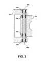
- FIG. 3is a cross-section view depicting the coupling of two links of an articulated arm according to one aspect of the subject technology.
- FIG. 4is an exploded view of a spring balancer and linear slider arranged on an articulated arm according to one aspect of the subject technology.
- FIG. 1is a perspective view of a balancer swivel arm assembly according to one aspect of the subject technology.
- balancer swivel arm assembly 10includes articulated arm 20 , spring balancer 30 and linear slider 40 .
- articulated arm 20is configured to be pivotably attached to a work station, such as a work station in a hard drive manufacturing assembly line.
- Linear slider 40is slidably mounted on a distal end of articulated arm 20 with screwdriver 50 mounted thereon.
- Spring balancer 30also is mounted on the distal end of articulated arm 20 and is coupled to linear slider 40 to support linear slider 40 and screwdriver 50 through a linear range of motion.
- the foregoing components of balancer swivel arm assembly 10are described in more detail below.
- FIG. 2is a cross-sectional view of balancer swivel arm assembly 10 without screwdriver 50 mounted to linear slider 40 according to one aspect of the subject technology.
- articulated arm 20comprises proximal link 21 , first intermediate link 22 , second intermediate link 23 , distal link 24 and slider bracket 25 .
- Proximal link 21is configured to be attached to a work station or a wall structure adjacent to a work station.
- First intermediate link 22is pivotably coupled to proximal link 21 with first rotary shaft 26 a .
- Second intermediate link 23is pivotably coupled to first intermediate link 22 with second rotary shaft 26 b .
- Distal link 24is pivotably coupled to second intermediate link 23 with third rotary shaft 26 c .
- Slider bracket 25is pivotably coupled to distal link 24 .
- proximal link 21is configured to be attached to a work station or a wall structure adjacent to a work station.
- proximal link 21may comprise a bracket configured to be attached to the work station or adjacent wall using one or more fasteners, such as screws 27 a and 27 b depicted in FIG. 2 .
- Screws 27 a and 27 bmay secure proximal link 21 to a support structure of the work station or a mounting surface of an adjacent wall suitable to support balancer swivel arm assembly 10 during use by an operator.
- proximal link 21may be mounted using different types of fasteners and different numbers of fasteners than are represented in FIG. 2 .
- proximal link 21may be detachably mounted to the work station or adjacent wall.
- proximal link 21may be configured to be more permanently mounted to the work station by welding proximal link 21 to a support structure on the work station.
- FIG. 3is a cross-sectional view showing the coupling of first intermediate link 22 to second intermediate link 23 according to one aspect of the subject technology.
- first intermediate link 22is pivotably coupled to second intermediate link 23 with second rotary shaft 26 b .
- Second rotary shaft 26 bis supported within axial bores of first intermediate link 22 and second intermediate link 23 by radial bearings 28 a to 28 d .
- Radial bearings 28 a to 28 dallow first intermediate link 22 and second intermediate link 23 to pivot with respect to each other around second rotary shaft 26 b .
- the outer openings of the axial bore in first intermediate link 22are sealed with end caps 29 a and 29 b.
- Radial bearings 28 a to 28 dare not limited to any particular type of bearing.
- radial bearings 28 a to 28 dmay be a low dust, greased ball bearing or a non-greased ball bearing.
- end caps 29 a and 29 bmay be used to seal the ends of the axial bores in first intermediate link 22 , as shown in FIG. 3 .
- cleanroom-safe plastic bushings or washersmay be placed between adjacent surfaces of first intermediate link 22 and second intermediate link 23 to prevent rubbing between these two components.
- first intermediate link 22 and second intermediate link 23are used to pivotably couple distal link 21 to first intermediate link 22 with first rotary shaft 26 a and to pivotably couple second intermediate link 23 to distal link 24 with third rotary shaft 26 c . While not shown in detail, similar arrangements of radial bearings and end caps are used to support and contain the respective rotary shafts.
- distal link 24is pivotably coupled to slider bracket 25 .
- distal link 24includes an integral rotary shaft that is encased by a coupling arm of slider bracket 25 .
- a radial bearingis arranged between the integral rotary shaft of distal link 24 and an inner surface of the coupling arm of slider bracket 25 . The radial bearing allows slider bracket 25 to pivot with respect to distal link 24 .
- first rotary shaft 26 ais aligned with axis A
- second rotary shaft 26 bis aligned with axis B
- third rotary shaft 26 cis aligned with axis C
- the integral rotary shaft of distal link 24is aligned with axis D.
- axes A, B, C and Dare parallel to one another. With this arrangement, the links of articulated arm 20 may be pivoted with respect to each other to position articulated arm 20 within a plane perpendicular to axes A, B, C and D.
- articulated arm 20may be positioned within a plane parallel to the work surface of the work station.
- the four pivotable linksi.e., proximal link 21 , first intermediate link 22 , second intermediate link 23 and distal link 24 ) of articulated arm 20 provide a wide range of motion within the plane while allowing articulated arm 20 to function within a relatively small work area.
- Alternative configurations of articulated arm 20may include only a single intermediate link or may include more than two intermediate links without departing from the scope of the subject technology.
- the number of intermediate linksmay vary depending on the arrangement and dimensions of the work station in which articulated arm 20 is to be operated as well as the size and weight of the tool to be supported on the distal end of articulated arm 20 .
- Articulated arm 20allows an operator to position balancer swivel arm assembly 10 within a plane parallel to the work surface of a work station.
- Spring balancer 30 and linear slider 40allow the operator to position a power tool mounted on the distal end of articulated arm 20 through a linear range of motion along axis E depicted in FIG. 2 .
- Spring balancer 30 and linear slider 40are illustrated in more detail in FIG. 4 .
- FIG. 4is an exploded view of components of spring balancer 30 and linear slider 40 .
- spring balancer 30includes rotating cable assembly 31 , inner cover 32 and outer cover 33 .
- Linear slider 40includes rail 41 , carriage 42 and tool mount 43 .
- rotating cable assembly 31is mounted to slider bracket 25 and comprises a spool having a cable wound thereon.
- the spoolis coupled to a torsion spring and arranged to spin around an axel. As the cable is unwound from the spool, the tension on the torsion spring increases to provide a restorative force to rewind the cable onto the spool.
- the spool with the cable wound thereonis partially enclosed by inner cover 32 .
- Outer cover 33partially encloses rotating cable assembly 31 and inner cover 32 .
- Inner cover 32 and outer cover 33are arranged around rotating cable assembly 31 to reduce the possibility of contaminating a cleanroom environment as rotating cable assembly 31 unwinds and rewinds during operation of balancer swivel arm assembly 10 by an operator.
- inner cover 32 and outer cover 33are intended to contain pollutants such as lubricant, dust and particles generated by components rubbing together or colliding within a cavity partially defined a base portion of rotating cable assembly 31 and outer cover 33 .
- a vacuummay be applied to the cavity through vacuum port 34 depicted in FIG. 2 to evacuate any pollutants that may be generated therein.
- Rail 41is mounted in a cavity of slider bracket 25 .
- Carriage 42is attached to rail 41 and configured to slide along rail 41 through a linear range motion parallel to axes A, B, C and D.
- the subject technologyis not limited to any particular type of rail and carriage.
- cover 44may be attached to slider bracket 25 to partially enclose the cavity containing rail 41 and carriage 42 .
- a vacuummay be applied to the cavity in slider bracket 25 containing rail 41 and carriage 42 through vacuum port 45 depicted in FIG. 2 .
- pollutantssuch lubricant, dust and particles created by components rubbing together or colliding may be evacuated from the cavity rather than being expelled into a cleanroom environment.
- cleanroom safe shock absorbing materialsmay be placed at the ends of rail 41 to absorb any impact and minimize particle generation as carriage 42 reaches the limits of the linear range of motion along rail 41 .
- Tool mount 43is attached to carriage 42 and is configured to hold a tool, such as screwdriver 50 depicted in FIG. 1 .
- Tool mount 43may use a conventional clamping mechanism to hold the tool.
- tool mount 43may use a proprietary mechanism specifically designed to hold a particular tool or brand of tool.
- Tool mount 43may be arranged to hold the tool in a particular alignment as tool mount 43 and carriage 42 move through the linear range of motion along rail 41 .
- tool mount 43may hold the tool, such as screwdriver 50 , in alignment with axis E depicted in FIG. 3 , which is parallel to axes A, B, C and D.
- tool mount 43also may prevent the rotation of a tool attached to tool mount 43 in order to absorb torque generated by the tool, such as a screwdriver, rather than allowing that torque to be transmitted to the hands and wrists of an operator.
- the cable of rotating cable assembly 31is attached to carriage 42 to support carriage 42 , tool mount 43 and any tool mounted thereon through linear range of motion along axis E.
- the torsion spring in rotating cable assembly 31may be adjustable to allow different tools having different weights to be supported.
- the restorative force of the torsion spring in rotating cable assembly 31allows a tool mounted to tool mount 43 to be positioned along axis E with minimal effort by an operator.
- operation of articulated arm 20allows the tool mounted to tool mount 43 to be positioned within a plane parallel to the work surface of a work station with minimal effort.
- a screwdrivermay be mounted in tool mount 43 .
- the screwdrivermay be electrically driven or pneumatic.
- Other types of power toolsalso may be mounted to tool mount 43 to facilitate the supported positioning and operation of the tool by an operator using balancer swivel arm assembly 10 .
- balancer swivel arm assembly 10are not limited to any particular type of materials.
- electro nickel plated aluminum and/or electro polished stainless steelmay be used to form the links of articulated arm 20 as well as components of spring balancer 30 and linear slider 40 .
- relatively heavy, rigid materialsmay be used to form articulated arm 20 , which must support spring balancer 30 , linear slider 40 and a mounted tool through a range of extended positions.
- relatively lighter materialsmay be used to form the components of spring balancer 30 and linear slider 40 in order to minimize the weight on the distal end of articulated arm 20 .
- the links of articulated arm 20are coupled with radial bearing joints which provide rigid support for maintaining articulated arm 20 within a plane parallel to the work surface of a work station. Furthermore, positioning linear slider 40 at the distal end of articulated arm 20 as close as possible to the tool minimizes any tilting of the tool during operation due to a cantilever moment applied to linear slider 40 .
- the multiple links described aboveallow balancer swivel arm assembly 20 to be operated within a relatively confined work station.
- an operatormay use balancer swivel arm assembly to support a tool during a large number of repetitive operations, such as driving screws, while minimizing fatigue to the operator by supporting the tool in a position perpendicular to the work surface of the work station within a wide range of motion in a plane parallel to the work surface.
- a phrase such as an “aspect”does not imply that such aspect is essential to the subject technology or that such aspect applies to all configurations of the subject technology.
- a disclosure relating to an aspectmay apply to all configurations, or one or more configurations.
- a phrase such as an aspectmay refer to one or more aspects and vice versa.
- a phrase such as a “configuration”does not imply that such configuration is essential to the subject technology or that such configuration applies to all configurations of the subject technology.
- a disclosure relating to a configurationmay apply to all configurations, or one or more configurations.
- a phrase such a configurationmay refer to one or more configurations and vice versa.
Landscapes
- Engineering & Computer Science (AREA)
- General Engineering & Computer Science (AREA)
- Mechanical Engineering (AREA)
- Manipulator (AREA)
Abstract
Description
Claims (15)
Priority Applications (2)
| Application Number | Priority Date | Filing Date | Title |
|---|---|---|---|
| US12/645,410US8424824B1 (en) | 2009-12-22 | 2009-12-22 | Balancer swivel arm assembly |
| US13/790,317US8777934B1 (en) | 2009-12-22 | 2013-03-08 | Balancer swivel arm assembly |
Applications Claiming Priority (1)
| Application Number | Priority Date | Filing Date | Title |
|---|---|---|---|
| US12/645,410US8424824B1 (en) | 2009-12-22 | 2009-12-22 | Balancer swivel arm assembly |
Related Child Applications (1)
| Application Number | Title | Priority Date | Filing Date |
|---|---|---|---|
| US13/790,317DivisionUS8777934B1 (en) | 2009-12-22 | 2013-03-08 | Balancer swivel arm assembly |
Publications (1)
| Publication Number | Publication Date |
|---|---|
| US8424824B1true US8424824B1 (en) | 2013-04-23 |
Family
ID=48094757
Family Applications (2)
| Application Number | Title | Priority Date | Filing Date |
|---|---|---|---|
| US12/645,410Expired - Fee RelatedUS8424824B1 (en) | 2009-12-22 | 2009-12-22 | Balancer swivel arm assembly |
| US13/790,317Expired - Fee RelatedUS8777934B1 (en) | 2009-12-22 | 2013-03-08 | Balancer swivel arm assembly |
Family Applications After (1)
| Application Number | Title | Priority Date | Filing Date |
|---|---|---|---|
| US13/790,317Expired - Fee RelatedUS8777934B1 (en) | 2009-12-22 | 2013-03-08 | Balancer swivel arm assembly |
Country Status (1)
| Country | Link |
|---|---|
| US (2) | US8424824B1 (en) |
Cited By (23)
| Publication number | Priority date | Publication date | Assignee | Title |
|---|---|---|---|---|
| US20130318765A1 (en)* | 2012-05-30 | 2013-12-05 | Johnson Outdoors Inc. | Universal Mounting Bracket for Outboard Marine Equipment |
| US20140151948A1 (en)* | 2012-12-05 | 2014-06-05 | MKIND, Inc. | Vertically Adjustable Work Station |
| US8777934B1 (en) | 2009-12-22 | 2014-07-15 | Western Digital Technologies, Inc. | Balancer swivel arm assembly |
| US8964179B2 (en) | 2013-02-21 | 2015-02-24 | Western Digital Technologies, Inc. | Method and apparatus for measuring a pitch static attitude of a head stack assembly |
| US9022444B1 (en) | 2013-05-20 | 2015-05-05 | Western Digital Technologies, Inc. | Vacuum nozzle having back-pressure release hole |
| US9120232B1 (en) | 2013-07-26 | 2015-09-01 | Western Digital Technologies, Inc. | Vacuum pick-up end effector with improved vacuum reading for small surface |
| US9150360B1 (en) | 2013-05-16 | 2015-10-06 | Western Digital Technologies, Inc. | Mechanism to deliver fastener vertically |
| US9157817B1 (en) | 2014-06-09 | 2015-10-13 | Western Digital Technologies, Inc. | HSA swage metrology calibration using solid weight gauge and torque sensor |
| US9180563B2 (en) | 2013-03-08 | 2015-11-10 | Western Digital Technologies, Inc. | De-swage machine for removal of a head from a head stack assembly and method of using the same |
| US9230579B1 (en) | 2012-09-21 | 2016-01-05 | Western Digital Technologies, Inc. | Comb gripper for use with a shipping comb and a ramp in the assembly of a disk drive |
| US9236071B1 (en) | 2014-12-21 | 2016-01-12 | Western Digital Technologies, Inc. | Etching continuous periodic pattern on a suspension to adjust pitch and roll static attitude |
| US9275677B1 (en) | 2010-09-30 | 2016-03-01 | Western Digital Technologies, Inc. | Hard disk drive top cover removal |
| US9286922B1 (en) | 2015-06-26 | 2016-03-15 | Western Digital Technologies, Inc. | Adaptive tacking of head gimbal assembly long tail and HSA arm slot |
| US9299372B1 (en) | 2015-04-29 | 2016-03-29 | Western Digital Technologies, Inc. | Swage key enabling simultaneous transfer of two head gimbal assemblies onto two corresponding actuator pivot flex assembly arms |
| US9404939B1 (en) | 2014-06-24 | 2016-08-02 | Western Digital (Fremont), Llc | Pre-amplifier cartridge for test equipment of head gimbal assembly |
| US9737979B1 (en) | 2014-02-13 | 2017-08-22 | Western Digital Technologies, Inc. | Vacuum embedded bit for screw drivers |
| US9799377B1 (en) | 2015-05-01 | 2017-10-24 | Western Digital Technologies, Inc. | Gas-charging head with integral valves |
| US9895725B1 (en) | 2014-10-07 | 2018-02-20 | Western Digital Technologies, Inc. | Disk clamp and motor hub cleaning with stamping adhesive |
| US9996071B2 (en) | 2014-06-24 | 2018-06-12 | Western Digital Technologies, Inc. | Moveable slider for use in a device assembly process |
| US10039219B1 (en) | 2015-09-28 | 2018-07-31 | Western Digital Technologies, Inc. | Method and devices for picking and placing workpieces into devices under manufacture using dual robots |
| EP3738717A1 (en)* | 2019-05-14 | 2020-11-18 | Siemens Gamesa Renewable Energy A/S | Mounting arrangement |
| IT201900015944A1 (en)* | 2019-09-10 | 2021-03-10 | Tecna Spa | BALANCER FOR TOOLS. |
| US20210402538A1 (en)* | 2020-06-30 | 2021-12-30 | Gulfstream Aerospace Corporation | Apparatus and method for holding and/or using a tool |
Families Citing this family (2)
| Publication number | Priority date | Publication date | Assignee | Title |
|---|---|---|---|---|
| EP3193767B1 (en) | 2014-09-15 | 2022-04-20 | Covidien LP | Robotically controlling surgical assemblies |
| SE542019C2 (en)* | 2018-06-08 | 2020-02-11 | Fumex Ab | Support arm arrangement for a local gas extractor, and a local gas extractor with such a support arm arrangement |
Citations (27)
| Publication number | Priority date | Publication date | Assignee | Title |
|---|---|---|---|---|
| US3279045A (en) | 1964-08-03 | 1966-10-18 | Paul H Dixon | Assembling mechanism |
| US3694888A (en) | 1970-10-22 | 1972-10-03 | Groov Pin Corp | Insert driver device |
| US4863133A (en)* | 1987-05-26 | 1989-09-05 | Leonard Medical | Arm device for adjustable positioning of a medical instrument or the like |
| US4924732A (en)* | 1987-07-27 | 1990-05-15 | Alliance Automation Systems, Inc. | Power driven screwdriver with vacuum for removing contaminants |
| US5109736A (en)* | 1990-07-27 | 1992-05-05 | Dixon Automatic Tool, Inc. | Automatic assembly machine with steering/up-down control handle |
| US5213292A (en) | 1992-04-22 | 1993-05-25 | Woodhead Industries, Inc. | Tension adjusting mechanism for tool balancer |
| US5367924A (en)* | 1993-07-26 | 1994-11-29 | Edlo Sales & Engineering Inc. | Support arm for a power screwdriver |
| US5544554A (en) | 1994-10-20 | 1996-08-13 | International Business Machines Corporation | Ergonomic torque wrench mounting |
| US5580021A (en) | 1995-05-15 | 1996-12-03 | Gillanders; David D. | Power tool suspension mechanism with momentary tension relieving device |
| US5609316A (en) | 1995-09-05 | 1997-03-11 | Tigliev; George S. | Suspension system for surgical microscope |
| US6065373A (en) | 1998-09-28 | 2000-05-23 | Nitto Seiko Co., Ltd. | Power tool holding assembly that enables easier operation of a power tool |
| US6276489B1 (en)* | 1999-02-10 | 2001-08-21 | Genie Industries, Inc. | Flanged cross tubes for use in scissors linkages |
| US20030234332A1 (en)* | 2002-06-25 | 2003-12-25 | Ching-Hui Yen | Height adjustable apparatus for supporting flat monitor |
| US6702238B1 (en)* | 2003-03-28 | 2004-03-09 | Top Victory Electronics Co., Ltd. | Adjustable supporting device for a display panel |
| US6711972B1 (en) | 2002-10-09 | 2004-03-30 | Visteon Global Technologies, Inc. | Articulated support for manually-operated tool |
| US6736033B2 (en) | 2001-06-07 | 2004-05-18 | Festo Ag & Co. | Device for the control of the thrust force of a manually operated pneumatic screw driver |
| US7036787B1 (en)* | 2005-02-04 | 2006-05-02 | Taiwan Thick-Film Ind. Corp. | Display strut adjusting structure |
| US7055789B2 (en) | 2002-05-14 | 2006-06-06 | Automation Tool Company | Articulating tool arm with positional feedback |
| US20060219849A1 (en)* | 2005-04-04 | 2006-10-05 | Fulfil Tech. Co., Ltd. | Height-adjustable support for a display device |
| US7243892B2 (en)* | 2003-01-09 | 2007-07-17 | Csav, Inc. | Articulated mount |
| US7325777B2 (en) | 2005-02-18 | 2008-02-05 | Gordon Daniel Thiessen | Portable articulating tool support |
| USD569381S1 (en)* | 2007-01-03 | 2008-05-20 | Bell'o International Corp. | Flat panel display mount |
| US7556626B2 (en)* | 2003-01-07 | 2009-07-07 | Olympus Corporation | Medical instrument holding apparatus |
| US7621490B2 (en)* | 2007-03-02 | 2009-11-24 | Qisda Corporation | Height adjustable holding apparatus |
| US20100102188A1 (en)* | 2008-10-28 | 2010-04-29 | Lien-Ming Liu | Elevating device with latching function |
| US7708243B2 (en)* | 2008-07-01 | 2010-05-04 | Hong Fu Jin Precision Industry (Shenzhen) Co., Ltd. | Height-adjustable stand |
| US8127643B1 (en)* | 2005-11-30 | 2012-03-06 | Western Digital Technologies, Inc. | Methods, devices and systems for screw feeding by vacuum and gravity |
Family Cites Families (25)
| Publication number | Priority date | Publication date | Assignee | Title |
|---|---|---|---|---|
| US3333613A (en)* | 1966-03-07 | 1967-08-01 | Groov Pin Corp | Insert driver device |
| US3910325A (en)* | 1974-11-04 | 1975-10-07 | Dixon Automatic Tool | Automatic fastener driving machine with hand-held driving gun |
| US4782726A (en)* | 1987-01-13 | 1988-11-08 | Ryder Internation Corporation | Lead screw driver |
| DE3921857A1 (en)* | 1989-07-04 | 1991-01-17 | Wild Leitz Ag | TRIPOD EQUIPPED WITH ADDITIONAL DEVICES FOR THE MOUNTING OF A FREELY POSITIONABLE DEVICE |
| US5597146A (en)* | 1991-08-05 | 1997-01-28 | Putman; J. Michael | Rail-mounted stabilizer for surgical instrument |
| US5825536A (en)* | 1994-09-12 | 1998-10-20 | Olympus Optical Co., Ltd. | Surgical microscope unit |
| JP2781164B2 (en)* | 1995-12-28 | 1998-07-30 | 三鷹光器株式会社 | Auto-balance structure of medical stand device |
| US6788018B1 (en)* | 1999-08-03 | 2004-09-07 | Intuitive Surgical, Inc. | Ceiling and floor mounted surgical robot set-up arms |
| JP4222706B2 (en)* | 2000-03-22 | 2009-02-12 | オリンパス株式会社 | Medical instrument holding device |
| JP2005524442A (en)* | 2002-05-02 | 2005-08-18 | ジーエムピー サージカル ソリューションズ インコーポレイテッド | Device for positioning medical instruments |
| JP4270889B2 (en)* | 2003-01-15 | 2009-06-03 | オリンパス株式会社 | Medical instrument holding device |
| JP4525155B2 (en)* | 2004-04-26 | 2010-08-18 | Smc株式会社 | Linear actuator |
| US7303527B2 (en)* | 2004-07-26 | 2007-12-04 | Ng Raymond C | Medical examination apparatus |
| US7670281B2 (en)* | 2004-10-07 | 2010-03-02 | Kronner Richard F | Instrument support apparatus |
| US7420731B2 (en)* | 2004-12-14 | 2008-09-02 | Piontkowski Paul K | Surgical microscope support system |
| US7837674B2 (en)* | 2005-01-24 | 2010-11-23 | Intuitive Surgical Operations, Inc. | Compact counter balance for robotic surgical systems |
| US20060237618A1 (en)* | 2005-03-15 | 2006-10-26 | Chiang Sun H | Support device for monitor, display or objects |
| US7559590B1 (en)* | 2005-10-19 | 2009-07-14 | Western Digital Technologies, Inc. | Pressure transmission assembly for mounting to a robotic device having a rotatable end effector |
| USD558561S1 (en)* | 2006-07-26 | 2008-01-01 | Peerless Industries, Inc. | Articulating mount |
| US7374123B2 (en)* | 2006-09-05 | 2008-05-20 | Louis A. Kish | Rewind mechanism |
| CN101498396B (en)* | 2008-01-30 | 2011-07-27 | 鸿富锦精密工业(深圳)有限公司 | Lifting mechanism |
| US8182009B2 (en)* | 2008-03-13 | 2012-05-22 | Xyratex Technology, Ltd. | End effector |
| US7780125B2 (en)* | 2008-07-14 | 2010-08-24 | Syncmold Enterprise Corp. | Support frame for a variety kinds of display devices |
| KR101030371B1 (en)* | 2009-04-27 | 2011-04-20 | 국립암센터 | Endoscopic adjustment device for minimally invasive surgery |
| US8424824B1 (en) | 2009-12-22 | 2013-04-23 | Western Digital Technologies, Inc. | Balancer swivel arm assembly |
- 2009
- 2009-12-22USUS12/645,410patent/US8424824B1/ennot_activeExpired - Fee Related
- 2013
- 2013-03-08USUS13/790,317patent/US8777934B1/ennot_activeExpired - Fee Related
Patent Citations (27)
| Publication number | Priority date | Publication date | Assignee | Title |
|---|---|---|---|---|
| US3279045A (en) | 1964-08-03 | 1966-10-18 | Paul H Dixon | Assembling mechanism |
| US3694888A (en) | 1970-10-22 | 1972-10-03 | Groov Pin Corp | Insert driver device |
| US4863133A (en)* | 1987-05-26 | 1989-09-05 | Leonard Medical | Arm device for adjustable positioning of a medical instrument or the like |
| US4924732A (en)* | 1987-07-27 | 1990-05-15 | Alliance Automation Systems, Inc. | Power driven screwdriver with vacuum for removing contaminants |
| US5109736A (en)* | 1990-07-27 | 1992-05-05 | Dixon Automatic Tool, Inc. | Automatic assembly machine with steering/up-down control handle |
| US5213292A (en) | 1992-04-22 | 1993-05-25 | Woodhead Industries, Inc. | Tension adjusting mechanism for tool balancer |
| US5367924A (en)* | 1993-07-26 | 1994-11-29 | Edlo Sales & Engineering Inc. | Support arm for a power screwdriver |
| US5544554A (en) | 1994-10-20 | 1996-08-13 | International Business Machines Corporation | Ergonomic torque wrench mounting |
| US5580021A (en) | 1995-05-15 | 1996-12-03 | Gillanders; David D. | Power tool suspension mechanism with momentary tension relieving device |
| US5609316A (en) | 1995-09-05 | 1997-03-11 | Tigliev; George S. | Suspension system for surgical microscope |
| US6065373A (en) | 1998-09-28 | 2000-05-23 | Nitto Seiko Co., Ltd. | Power tool holding assembly that enables easier operation of a power tool |
| US6276489B1 (en)* | 1999-02-10 | 2001-08-21 | Genie Industries, Inc. | Flanged cross tubes for use in scissors linkages |
| US6736033B2 (en) | 2001-06-07 | 2004-05-18 | Festo Ag & Co. | Device for the control of the thrust force of a manually operated pneumatic screw driver |
| US7055789B2 (en) | 2002-05-14 | 2006-06-06 | Automation Tool Company | Articulating tool arm with positional feedback |
| US20030234332A1 (en)* | 2002-06-25 | 2003-12-25 | Ching-Hui Yen | Height adjustable apparatus for supporting flat monitor |
| US6711972B1 (en) | 2002-10-09 | 2004-03-30 | Visteon Global Technologies, Inc. | Articulated support for manually-operated tool |
| US7556626B2 (en)* | 2003-01-07 | 2009-07-07 | Olympus Corporation | Medical instrument holding apparatus |
| US7243892B2 (en)* | 2003-01-09 | 2007-07-17 | Csav, Inc. | Articulated mount |
| US6702238B1 (en)* | 2003-03-28 | 2004-03-09 | Top Victory Electronics Co., Ltd. | Adjustable supporting device for a display panel |
| US7036787B1 (en)* | 2005-02-04 | 2006-05-02 | Taiwan Thick-Film Ind. Corp. | Display strut adjusting structure |
| US7325777B2 (en) | 2005-02-18 | 2008-02-05 | Gordon Daniel Thiessen | Portable articulating tool support |
| US20060219849A1 (en)* | 2005-04-04 | 2006-10-05 | Fulfil Tech. Co., Ltd. | Height-adjustable support for a display device |
| US8127643B1 (en)* | 2005-11-30 | 2012-03-06 | Western Digital Technologies, Inc. | Methods, devices and systems for screw feeding by vacuum and gravity |
| USD569381S1 (en)* | 2007-01-03 | 2008-05-20 | Bell'o International Corp. | Flat panel display mount |
| US7621490B2 (en)* | 2007-03-02 | 2009-11-24 | Qisda Corporation | Height adjustable holding apparatus |
| US7708243B2 (en)* | 2008-07-01 | 2010-05-04 | Hong Fu Jin Precision Industry (Shenzhen) Co., Ltd. | Height-adjustable stand |
| US20100102188A1 (en)* | 2008-10-28 | 2010-04-29 | Lien-Ming Liu | Elevating device with latching function |
Cited By (25)
| Publication number | Priority date | Publication date | Assignee | Title |
|---|---|---|---|---|
| US8777934B1 (en) | 2009-12-22 | 2014-07-15 | Western Digital Technologies, Inc. | Balancer swivel arm assembly |
| US9275677B1 (en) | 2010-09-30 | 2016-03-01 | Western Digital Technologies, Inc. | Hard disk drive top cover removal |
| US10196120B2 (en)* | 2012-05-30 | 2019-02-05 | Johnson Outdoors Inc. | Universal mounting bracket for outboard marine equipment |
| US20130318765A1 (en)* | 2012-05-30 | 2013-12-05 | Johnson Outdoors Inc. | Universal Mounting Bracket for Outboard Marine Equipment |
| US9230579B1 (en) | 2012-09-21 | 2016-01-05 | Western Digital Technologies, Inc. | Comb gripper for use with a shipping comb and a ramp in the assembly of a disk drive |
| US20140151948A1 (en)* | 2012-12-05 | 2014-06-05 | MKIND, Inc. | Vertically Adjustable Work Station |
| US8964179B2 (en) | 2013-02-21 | 2015-02-24 | Western Digital Technologies, Inc. | Method and apparatus for measuring a pitch static attitude of a head stack assembly |
| US9308609B2 (en) | 2013-03-08 | 2016-04-12 | Western Digital Technologies, Inc. | De-swage machine for removal of a head from a head stack assembly and method of using the same |
| US9180563B2 (en) | 2013-03-08 | 2015-11-10 | Western Digital Technologies, Inc. | De-swage machine for removal of a head from a head stack assembly and method of using the same |
| US9150360B1 (en) | 2013-05-16 | 2015-10-06 | Western Digital Technologies, Inc. | Mechanism to deliver fastener vertically |
| US9022444B1 (en) | 2013-05-20 | 2015-05-05 | Western Digital Technologies, Inc. | Vacuum nozzle having back-pressure release hole |
| US9120232B1 (en) | 2013-07-26 | 2015-09-01 | Western Digital Technologies, Inc. | Vacuum pick-up end effector with improved vacuum reading for small surface |
| US9737979B1 (en) | 2014-02-13 | 2017-08-22 | Western Digital Technologies, Inc. | Vacuum embedded bit for screw drivers |
| US9157817B1 (en) | 2014-06-09 | 2015-10-13 | Western Digital Technologies, Inc. | HSA swage metrology calibration using solid weight gauge and torque sensor |
| US9996071B2 (en) | 2014-06-24 | 2018-06-12 | Western Digital Technologies, Inc. | Moveable slider for use in a device assembly process |
| US9404939B1 (en) | 2014-06-24 | 2016-08-02 | Western Digital (Fremont), Llc | Pre-amplifier cartridge for test equipment of head gimbal assembly |
| US9895725B1 (en) | 2014-10-07 | 2018-02-20 | Western Digital Technologies, Inc. | Disk clamp and motor hub cleaning with stamping adhesive |
| US9236071B1 (en) | 2014-12-21 | 2016-01-12 | Western Digital Technologies, Inc. | Etching continuous periodic pattern on a suspension to adjust pitch and roll static attitude |
| US9299372B1 (en) | 2015-04-29 | 2016-03-29 | Western Digital Technologies, Inc. | Swage key enabling simultaneous transfer of two head gimbal assemblies onto two corresponding actuator pivot flex assembly arms |
| US9799377B1 (en) | 2015-05-01 | 2017-10-24 | Western Digital Technologies, Inc. | Gas-charging head with integral valves |
| US9286922B1 (en) | 2015-06-26 | 2016-03-15 | Western Digital Technologies, Inc. | Adaptive tacking of head gimbal assembly long tail and HSA arm slot |
| US10039219B1 (en) | 2015-09-28 | 2018-07-31 | Western Digital Technologies, Inc. | Method and devices for picking and placing workpieces into devices under manufacture using dual robots |
| EP3738717A1 (en)* | 2019-05-14 | 2020-11-18 | Siemens Gamesa Renewable Energy A/S | Mounting arrangement |
| IT201900015944A1 (en)* | 2019-09-10 | 2021-03-10 | Tecna Spa | BALANCER FOR TOOLS. |
| US20210402538A1 (en)* | 2020-06-30 | 2021-12-30 | Gulfstream Aerospace Corporation | Apparatus and method for holding and/or using a tool |
Also Published As
| Publication number | Publication date |
|---|---|
| US8777934B1 (en) | 2014-07-15 |
Similar Documents
| Publication | Publication Date | Title |
|---|---|---|
| US8424824B1 (en) | Balancer swivel arm assembly | |
| US8960042B2 (en) | Robot arm assembly | |
| US8429996B2 (en) | Robot arm assembly | |
| US8272290B2 (en) | Parallel robot | |
| US8534155B2 (en) | Robot arm assembly | |
| US20110126661A1 (en) | Industrial robot | |
| US7559590B1 (en) | Pressure transmission assembly for mounting to a robotic device having a rotatable end effector | |
| US20120067156A1 (en) | Robot for handling object | |
| US8516920B2 (en) | Robot arm assembly | |
| CN102059697B (en) | Translating branch chain and parallel robot using same | |
| US8201472B2 (en) | Robot arm | |
| US8429998B2 (en) | Parallel mechanism and moveable linkage thereof | |
| US8910539B2 (en) | Robot with reducer | |
| US8590415B2 (en) | Robotic arm assembly | |
| US20110100145A1 (en) | Rotation mechanism and robot using the same | |
| EP0188863A1 (en) | Direct drive robotic system | |
| US20110120245A1 (en) | Robot arm assembly | |
| US20100263471A1 (en) | Robot having delta kinematics | |
| US20110107867A1 (en) | Backlash adjustment mechanism and industrial robot using the same | |
| JP6725645B2 (en) | Robot arm mechanism | |
| KR102214202B1 (en) | Link structure for robot arm with gravity compensation device | |
| CN103286774A (en) | Articulated structure of multi-axis manipulator and manipulator including this structure | |
| CN101687320A (en) | Robotic manipulator utilizing rotary drive | |
| US20130125690A1 (en) | Robot arm assembly | |
| US11708882B2 (en) | Head mechanism and robot |
Legal Events
| Date | Code | Title | Description |
|---|---|---|---|
| AS | Assignment | Owner name:WESTERN DIGITAL TECHNOLOGIES, INC., CALIFORNIA Free format text:ASSIGNMENT OF ASSIGNORS INTEREST;ASSIGNORS:TAN, JIT HAN;PHUAH, SIE CHEANG;REEL/FRAME:023923/0384 Effective date:20100128 | |
| STCF | Information on status: patent grant | Free format text:PATENTED CASE | |
| AS | Assignment | Owner name:U.S. BANK NATIONAL ASSOCIATION, AS COLLATERAL AGENT, CALIFORNIA Free format text:SECURITY AGREEMENT;ASSIGNOR:WESTERN DIGITAL TECHNOLOGIES, INC.;REEL/FRAME:038744/0281 Effective date:20160512 Owner name:JPMORGAN CHASE BANK, N.A., AS COLLATERAL AGENT, ILLINOIS Free format text:SECURITY AGREEMENT;ASSIGNOR:WESTERN DIGITAL TECHNOLOGIES, INC.;REEL/FRAME:038744/0481 Effective date:20160512 Owner name:JPMORGAN CHASE BANK, N.A., AS COLLATERAL AGENT, ILLINOIS Free format text:SECURITY AGREEMENT;ASSIGNOR:WESTERN DIGITAL TECHNOLOGIES, INC.;REEL/FRAME:038722/0229 Effective date:20160512 Owner name:JPMORGAN CHASE BANK, N.A., AS COLLATERAL AGENT, IL Free format text:SECURITY AGREEMENT;ASSIGNOR:WESTERN DIGITAL TECHNOLOGIES, INC.;REEL/FRAME:038722/0229 Effective date:20160512 Owner name:U.S. BANK NATIONAL ASSOCIATION, AS COLLATERAL AGEN Free format text:SECURITY AGREEMENT;ASSIGNOR:WESTERN DIGITAL TECHNOLOGIES, INC.;REEL/FRAME:038744/0281 Effective date:20160512 Owner name:JPMORGAN CHASE BANK, N.A., AS COLLATERAL AGENT, IL Free format text:SECURITY AGREEMENT;ASSIGNOR:WESTERN DIGITAL TECHNOLOGIES, INC.;REEL/FRAME:038744/0481 Effective date:20160512 | |
| FPAY | Fee payment | Year of fee payment:4 | |
| AS | Assignment | Owner name:WESTERN DIGITAL TECHNOLOGIES, INC., CALIFORNIA Free format text:RELEASE BY SECURED PARTY;ASSIGNOR:U.S. BANK NATIONAL ASSOCIATION, AS COLLATERAL AGENT;REEL/FRAME:045501/0714 Effective date:20180227 | |
| FEPP | Fee payment procedure | Free format text:MAINTENANCE FEE REMINDER MAILED (ORIGINAL EVENT CODE: REM.); ENTITY STATUS OF PATENT OWNER: LARGE ENTITY | |
| LAPS | Lapse for failure to pay maintenance fees | Free format text:PATENT EXPIRED FOR FAILURE TO PAY MAINTENANCE FEES (ORIGINAL EVENT CODE: EXP.); ENTITY STATUS OF PATENT OWNER: LARGE ENTITY | |
| STCH | Information on status: patent discontinuation | Free format text:PATENT EXPIRED DUE TO NONPAYMENT OF MAINTENANCE FEES UNDER 37 CFR 1.362 | |
| FP | Lapsed due to failure to pay maintenance fee | Effective date:20210423 | |
| AS | Assignment | Owner name:WESTERN DIGITAL TECHNOLOGIES, INC., CALIFORNIA Free format text:RELEASE OF SECURITY INTEREST AT REEL 038744 FRAME 0481;ASSIGNOR:JPMORGAN CHASE BANK, N.A.;REEL/FRAME:058982/0556 Effective date:20220203 |