US8424763B2 - Method of forming an auto-calibration circuit or label - Google Patents
Method of forming an auto-calibration circuit or labelDownload PDFInfo
- Publication number
- US8424763B2 US8424763B2US12/551,654US55165409AUS8424763B2US 8424763 B2US8424763 B2US 8424763B2US 55165409 AUS55165409 AUS 55165409AUS 8424763 B2US8424763 B2US 8424763B2
- Authority
- US
- United States
- Prior art keywords
- layer
- label
- circuit
- auto
- test
- Prior art date
- Legal status (The legal status is an assumption and is not a legal conclusion. Google has not performed a legal analysis and makes no representation as to the accuracy of the status listed.)
- Expired - Fee Related, expires
Links
- 238000000034methodMethods0.000titleclaimsabstractdescription81
- 238000012360testing methodMethods0.000claimsabstractdescription132
- 238000003475laminationMethods0.000claimsabstractdescription49
- 239000000463materialSubstances0.000claimsabstractdescription30
- 239000004020conductorSubstances0.000claimsabstractdescription10
- 238000002679ablationMethods0.000claimsdescription25
- 239000012491analyteSubstances0.000claimsdescription24
- 229920000139polyethylene terephthalatePolymers0.000claimsdescription17
- 239000005020polyethylene terephthalateSubstances0.000claimsdescription17
- 229910052782aluminiumInorganic materials0.000claimsdescription15
- XAGFODPZIPBFFR-UHFFFAOYSA-NaluminiumChemical compound[Al]XAGFODPZIPBFFR-UHFFFAOYSA-N0.000claimsdescription15
- -1polyethylenePolymers0.000claimsdescription15
- PXHVJJICTQNCMI-UHFFFAOYSA-NNickelChemical compound[Ni]PXHVJJICTQNCMI-UHFFFAOYSA-N0.000claimsdescription6
- KDLHZDBZIXYQEI-UHFFFAOYSA-NPalladiumChemical compound[Pd]KDLHZDBZIXYQEI-UHFFFAOYSA-N0.000claimsdescription6
- 238000005259measurementMethods0.000claimsdescription4
- 229920000515polycarbonatePolymers0.000claimsdescription4
- 239000004417polycarbonateSubstances0.000claimsdescription4
- OKTJSMMVPCPJKN-UHFFFAOYSA-NCarbonChemical compound[C]OKTJSMMVPCPJKN-UHFFFAOYSA-N0.000claimsdescription3
- RYGMFSIKBFXOCR-UHFFFAOYSA-NCopperChemical compound[Cu]RYGMFSIKBFXOCR-UHFFFAOYSA-N0.000claimsdescription3
- 239000004793PolystyreneSubstances0.000claimsdescription3
- 239000004820Pressure-sensitive adhesiveSubstances0.000claimsdescription3
- 229910052799carbonInorganic materials0.000claimsdescription3
- 229910052802copperInorganic materials0.000claimsdescription3
- 239000010949copperSubstances0.000claimsdescription3
- PCHJSUWPFVWCPO-UHFFFAOYSA-NgoldChemical compound[Au]PCHJSUWPFVWCPO-UHFFFAOYSA-N0.000claimsdescription3
- 229910052737goldInorganic materials0.000claimsdescription3
- 239000010931goldSubstances0.000claimsdescription3
- 229910052759nickelInorganic materials0.000claimsdescription3
- 229910052763palladiumInorganic materials0.000claimsdescription3
- 229920003229poly(methyl methacrylate)Polymers0.000claimsdescription3
- 239000004926polymethyl methacrylateSubstances0.000claimsdescription3
- 239000004800polyvinyl chlorideSubstances0.000claimsdescription3
- 239000004698PolyethyleneSubstances0.000claims2
- 229920000573polyethylenePolymers0.000claims2
- 229920002223polystyrenePolymers0.000claims2
- 239000012530fluidSubstances0.000description23
- 230000003287optical effectEffects0.000description17
- 239000008103glucoseSubstances0.000description14
- WQZGKKKJIJFFOK-GASJEMHNSA-NGlucoseNatural productsOC[C@H]1OC(O)[C@H](O)[C@@H](O)[C@@H]1OWQZGKKKJIJFFOK-GASJEMHNSA-N0.000description12
- 239000003153chemical reaction reagentSubstances0.000description10
- 125000006850spacer groupChemical group0.000description10
- 108090000790EnzymesProteins0.000description7
- 102000004190EnzymesHuman genes0.000description7
- 229940088598enzymeDrugs0.000description7
- 239000000853adhesiveSubstances0.000description6
- 230000001070adhesive effectEffects0.000description6
- 210000004369bloodAnatomy0.000description6
- 239000008280bloodSubstances0.000description6
- 210000001124body fluidAnatomy0.000description6
- 239000010839body fluidSubstances0.000description6
- 230000008569processEffects0.000description6
- 229910052751metalInorganic materials0.000description5
- 239000002184metalSubstances0.000description5
- 229910052727yttriumInorganic materials0.000description5
- VWQVUPCCIRVNHF-UHFFFAOYSA-Nyttrium atomChemical compound[Y]VWQVUPCCIRVNHF-UHFFFAOYSA-N0.000description5
- BPYKTIZUTYGOLE-IFADSCNNSA-NBilirubinChemical compoundN1C(=O)C(C)=C(C=C)\C1=C\C1=C(C)C(CCC(O)=O)=C(CC2=C(C(C)=C(\C=C/3C(=C(C=C)C(=O)N\3)C)N2)CCC(O)=O)N1BPYKTIZUTYGOLE-IFADSCNNSA-N0.000description4
- HVYWMOMLDIMFJA-DPAQBDIFSA-NcholesterolChemical compoundC1C=C2C[C@@H](O)CC[C@]2(C)[C@@H]2[C@@H]1[C@@H]1CC[C@H]([C@H](C)CCCC(C)C)[C@@]1(C)CC2HVYWMOMLDIMFJA-DPAQBDIFSA-N0.000description4
- 238000000840electrochemical analysisMethods0.000description4
- 238000004806packaging method and processMethods0.000description4
- 238000012545processingMethods0.000description4
- 230000008859changeEffects0.000description3
- 230000006870functionEffects0.000description3
- XKRFYHLGVUSROY-UHFFFAOYSA-NArgonChemical compound[Ar]XKRFYHLGVUSROY-UHFFFAOYSA-N0.000description2
- 108010050375Glucose 1-DehydrogenaseProteins0.000description2
- 108010015776Glucose oxidaseProteins0.000description2
- 239000004366Glucose oxidaseSubstances0.000description2
- JVTAAEKCZFNVCJ-UHFFFAOYSA-MLactateChemical compoundCC(O)C([O-])=OJVTAAEKCZFNVCJ-UHFFFAOYSA-M0.000description2
- 239000004743PolypropyleneSubstances0.000description2
- JNDMLEXHDPKVFC-UHFFFAOYSA-Naluminum;oxygen(2-);yttrium(3+)Chemical compound[O-2].[O-2].[O-2].[Al+3].[Y+3]JNDMLEXHDPKVFC-UHFFFAOYSA-N0.000description2
- 238000003491arrayMethods0.000description2
- 230000008901benefitEffects0.000description2
- 235000012000cholesterolNutrition0.000description2
- 230000002950deficientEffects0.000description2
- 210000003722extracellular fluidAnatomy0.000description2
- 229940116332glucose oxidaseDrugs0.000description2
- 235000019420glucose oxidaseNutrition0.000description2
- NOESYZHRGYRDHS-UHFFFAOYSA-NinsulinChemical compoundN1C(=O)C(NC(=O)C(CCC(N)=O)NC(=O)C(CCC(O)=O)NC(=O)C(C(C)C)NC(=O)C(NC(=O)CN)C(C)CC)CSSCC(C(NC(CO)C(=O)NC(CC(C)C)C(=O)NC(CC=2C=CC(O)=CC=2)C(=O)NC(CCC(N)=O)C(=O)NC(CC(C)C)C(=O)NC(CCC(O)=O)C(=O)NC(CC(N)=O)C(=O)NC(CC=2C=CC(O)=CC=2)C(=O)NC(CSSCC(NC(=O)C(C(C)C)NC(=O)C(CC(C)C)NC(=O)C(CC=2C=CC(O)=CC=2)NC(=O)C(CC(C)C)NC(=O)C(C)NC(=O)C(CCC(O)=O)NC(=O)C(C(C)C)NC(=O)C(CC(C)C)NC(=O)C(CC=2NC=NC=2)NC(=O)C(CO)NC(=O)CNC2=O)C(=O)NCC(=O)NC(CCC(O)=O)C(=O)NC(CCCNC(N)=N)C(=O)NCC(=O)NC(CC=3C=CC=CC=3)C(=O)NC(CC=3C=CC=CC=3)C(=O)NC(CC=3C=CC(O)=CC=3)C(=O)NC(C(C)O)C(=O)N3C(CCC3)C(=O)NC(CCCCN)C(=O)NC(C)C(O)=O)C(=O)NC(CC(N)=O)C(O)=O)=O)NC(=O)C(C(C)CC)NC(=O)C(CO)NC(=O)C(C(C)O)NC(=O)C1CSSCC2NC(=O)C(CC(C)C)NC(=O)C(NC(=O)C(CCC(N)=O)NC(=O)C(CC(N)=O)NC(=O)C(NC(=O)C(N)CC=1C=CC=CC=1)C(C)C)CC1=CN=CN1NOESYZHRGYRDHS-UHFFFAOYSA-N0.000description2
- 230000007246mechanismEffects0.000description2
- 239000007769metal materialSubstances0.000description2
- 230000002093peripheral effectEffects0.000description2
- 229920000098polyolefinPolymers0.000description2
- 229920001155polypropylenePolymers0.000description2
- 230000009257reactivityEffects0.000description2
- 230000004044responseEffects0.000description2
- 238000006748scratchingMethods0.000description2
- 230000002393scratching effectEffects0.000description2
- 238000007789sealingMethods0.000description2
- 229910019901yttrium aluminum garnetInorganic materials0.000description2
- ZAMOUSCENKQFHK-UHFFFAOYSA-NChlorine atomChemical compound[Cl]ZAMOUSCENKQFHK-UHFFFAOYSA-N0.000description1
- PXGOKWXKJXAPGV-UHFFFAOYSA-NFluorineChemical compoundFFPXGOKWXKJXAPGV-UHFFFAOYSA-N0.000description1
- 229930091371FructoseNatural products0.000description1
- 239000005715FructoseSubstances0.000description1
- RFSUNEUAIZKAJO-ARQDHWQXSA-NFructoseChemical compoundOC[C@H]1O[C@](O)(CO)[C@@H](O)[C@@H]1ORFSUNEUAIZKAJO-ARQDHWQXSA-N0.000description1
- 102000001554HemoglobinsHuman genes0.000description1
- 108010054147HemoglobinsProteins0.000description1
- 102000004877InsulinHuman genes0.000description1
- 108090001061InsulinProteins0.000description1
- 239000004642PolyimideSubstances0.000description1
- 229920002472StarchPolymers0.000description1
- 230000005856abnormalityEffects0.000description1
- 238000002835absorbanceMethods0.000description1
- 230000009471actionEffects0.000description1
- 229910052786argonInorganic materials0.000description1
- WQZGKKKJIJFFOK-VFUOTHLCSA-Nbeta-D-glucoseChemical compoundOC[C@H]1O[C@@H](O)[C@H](O)[C@@H](O)[C@@H]1OWQZGKKKJIJFFOK-VFUOTHLCSA-N0.000description1
- 230000015572biosynthetic processEffects0.000description1
- 238000004364calculation methodMethods0.000description1
- 239000013626chemical specieSubstances0.000description1
- 229910052801chlorineInorganic materials0.000description1
- 239000000460chlorineSubstances0.000description1
- 238000012937correctionMethods0.000description1
- 238000001514detection methodMethods0.000description1
- 206010012601diabetes mellitusDiseases0.000description1
- 235000005911dietNutrition0.000description1
- 230000037213dietEffects0.000description1
- 229940079593drugDrugs0.000description1
- 239000003814drugSubstances0.000description1
- HDERJYVLTPVNRI-UHFFFAOYSA-Nethene;ethenyl acetateChemical groupC=C.CC(=O)OC=CHDERJYVLTPVNRI-UHFFFAOYSA-N0.000description1
- HJUFTIJOISQSKQ-UHFFFAOYSA-NfenoxycarbChemical compoundC1=CC(OCCNC(=O)OCC)=CC=C1OC1=CC=CC=C1HJUFTIJOISQSKQ-UHFFFAOYSA-N0.000description1
- YAGKRVSRTSUGEY-UHFFFAOYSA-NferricyanideChemical class[Fe+3].N#[C-].N#[C-].N#[C-].N#[C-].N#[C-].N#[C-]YAGKRVSRTSUGEY-UHFFFAOYSA-N0.000description1
- 238000001506fluorescence spectroscopyMethods0.000description1
- 229910052731fluorineInorganic materials0.000description1
- 239000011737fluorineSubstances0.000description1
- 239000007789gasSubstances0.000description1
- 239000011521glassSubstances0.000description1
- 238000005534hematocritMethods0.000description1
- 239000011261inert gasSubstances0.000description1
- 229940125396insulinDrugs0.000description1
- 229910052743kryptonInorganic materials0.000description1
- DNNSSWSSYDEUBZ-UHFFFAOYSA-Nkrypton atomChemical compound[Kr]DNNSSWSSYDEUBZ-UHFFFAOYSA-N0.000description1
- 238000010030laminatingMethods0.000description1
- 150000002632lipidsChemical class0.000description1
- 238000012423maintenanceMethods0.000description1
- 238000004519manufacturing processMethods0.000description1
- 150000002739metalsChemical class0.000description1
- 238000012986modificationMethods0.000description1
- 230000004048modificationEffects0.000description1
- 210000002381plasmaAnatomy0.000description1
- 239000011112polyethylene naphthalateSubstances0.000description1
- 229920001721polyimidePolymers0.000description1
- 229920005553polystyrene-acrylatePolymers0.000description1
- 229920002635polyurethanePolymers0.000description1
- 239000004814polyurethaneSubstances0.000description1
- 230000035945sensitivityEffects0.000description1
- 210000002966serumAnatomy0.000description1
- 239000008107starchSubstances0.000description1
- 235000019698starchNutrition0.000description1
- 238000012546transferMethods0.000description1
- 238000002235transmission spectroscopyMethods0.000description1
- 150000003626triacylglycerolsChemical class0.000description1
- 210000002700urineAnatomy0.000description1
- 229910052724xenonInorganic materials0.000description1
- FHNFHKCVQCLJFQ-UHFFFAOYSA-Nxenon atomChemical compound[Xe]FHNFHKCVQCLJFQ-UHFFFAOYSA-N0.000description1
Images


Classifications
- A—HUMAN NECESSITIES
- A61—MEDICAL OR VETERINARY SCIENCE; HYGIENE
- A61B—DIAGNOSIS; SURGERY; IDENTIFICATION
- A61B5/00—Measuring for diagnostic purposes; Identification of persons
- A61B5/145—Measuring characteristics of blood in vivo, e.g. gas concentration or pH-value ; Measuring characteristics of body fluids or tissues, e.g. interstitial fluid or cerebral tissue
- A61B5/14532—Measuring characteristics of blood in vivo, e.g. gas concentration or pH-value ; Measuring characteristics of body fluids or tissues, e.g. interstitial fluid or cerebral tissue for measuring glucose, e.g. by tissue impedance measurement
- A—HUMAN NECESSITIES
- A61—MEDICAL OR VETERINARY SCIENCE; HYGIENE
- A61B—DIAGNOSIS; SURGERY; IDENTIFICATION
- A61B5/00—Measuring for diagnostic purposes; Identification of persons
- A61B5/145—Measuring characteristics of blood in vivo, e.g. gas concentration or pH-value ; Measuring characteristics of body fluids or tissues, e.g. interstitial fluid or cerebral tissue
- A61B5/1495—Calibrating or testing of in-vivo probes
- G—PHYSICS
- G01—MEASURING; TESTING
- G01N—INVESTIGATING OR ANALYSING MATERIALS BY DETERMINING THEIR CHEMICAL OR PHYSICAL PROPERTIES
- G01N33/00—Investigating or analysing materials by specific methods not covered by groups G01N1/00 - G01N31/00
- G01N33/48—Biological material, e.g. blood, urine; Haemocytometers
- G01N33/483—Physical analysis of biological material
- G01N33/487—Physical analysis of biological material of liquid biological material
- G01N33/4875—Details of handling test elements, e.g. dispensing or storage, not specific to a particular test method
- G01N33/48771—Coding of information, e.g. calibration data, lot number
- A—HUMAN NECESSITIES
- A61—MEDICAL OR VETERINARY SCIENCE; HYGIENE
- A61B—DIAGNOSIS; SURGERY; IDENTIFICATION
- A61B2562/00—Details of sensors; Constructional details of sensor housings or probes; Accessories for sensors
- A61B2562/02—Details of sensors specially adapted for in-vivo measurements
- A61B2562/0295—Strip shaped analyte sensors for apparatus classified in A61B5/145 or A61B5/157
- A—HUMAN NECESSITIES
- A61—MEDICAL OR VETERINARY SCIENCE; HYGIENE
- A61B—DIAGNOSIS; SURGERY; IDENTIFICATION
- A61B5/00—Measuring for diagnostic purposes; Identification of persons
- A61B5/145—Measuring characteristics of blood in vivo, e.g. gas concentration or pH-value ; Measuring characteristics of body fluids or tissues, e.g. interstitial fluid or cerebral tissue
- A61B5/1455—Measuring characteristics of blood in vivo, e.g. gas concentration or pH-value ; Measuring characteristics of body fluids or tissues, e.g. interstitial fluid or cerebral tissue using optical sensors, e.g. spectral photometrical oximeters
- Y—GENERAL TAGGING OF NEW TECHNOLOGICAL DEVELOPMENTS; GENERAL TAGGING OF CROSS-SECTIONAL TECHNOLOGIES SPANNING OVER SEVERAL SECTIONS OF THE IPC; TECHNICAL SUBJECTS COVERED BY FORMER USPC CROSS-REFERENCE ART COLLECTIONS [XRACs] AND DIGESTS
- Y10—TECHNICAL SUBJECTS COVERED BY FORMER USPC
- Y10T—TECHNICAL SUBJECTS COVERED BY FORMER US CLASSIFICATION
- Y10T436/00—Chemistry: analytical and immunological testing
- Y10T436/25—Chemistry: analytical and immunological testing including sample preparation
- Y10T436/2575—Volumetric liquid transfer
Definitions
- the present inventiongenerally relates to a method of forming an auto-calibration circuit or label.
- the auto-calibration circuit or labelsare used in automatically calibrating instruments or meters that determine information related to an analyte (e.g., glucose concentration) in a fluid sample.
- an analytee.g., glucose concentration
- analytes in body fluidsis of great importance in the diagnoses and maintenance of certain physiological abnormalities. For example, lactate, cholesterol and bilirubin should be monitored in certain individuals. In particular, it is important that diabetic individuals frequently check the glucose level in their body fluids to regulate the glucose intake in their diets. The results of such tests can be used to determine what, if any, insulin or other medication needs to be administered.
- sensorsare used to test a sample of blood.
- a test sensorcontains biosensing or reagent material that reacts with blood glucose.
- the testing end of the sensoris adapted to be placed into the fluid being tested, for example, blood that has accumulated on a person's finger after the finger has been pricked.
- the fluidis drawn into a capillary channel that extends in the sensor from the testing end to the reagent material by capillary action so that a sufficient amount of fluid to be tested is drawn into the sensor.
- the fluidthen chemically reacts with the reagent material in the sensor resulting in an electrical signal indicative of the glucose level in the fluid being tested. This signal is supplied to the meter via contact areas located near the rear or contact end of the sensor and becomes the measures output.
- Optical systemsmay also test sensors that determine information related to an analyte (e.g., glucose concentration) in a fluid sample.
- an analytee.g., glucose concentration
- Diagnostic systemssuch as blood-glucose testing systems, typically calculate the actual glucose value based on a measured output and the known reactivity of the reagent-sensing element (test sensor) used to perform the test.
- the reactivity or lot-calibration information of the test sensormay be given to the user in several forms including a number or character that is entered into the instrument.
- One prior art methodincluded using an element that is similar to a test sensor, but which was capable of being recognized as a calibration element by the instrument.
- the test element's informationis read by the instrument or a memory element that is plugged into the instrument's microprocessor board for directly reading the test element.
- an auto-calibration circuit or labelis formed on a test sensor.
- a label or circuitis provided.
- the label or circuitincludes a first layer, a second layer and a lamination portion.
- the second layeris located between the first layer and the lamination portion.
- the second layerincludes conductive material.
- the label or circuitis applied to the test sensor via the lamination portion.
- portions of the second layerare ablated using a laser to form an auto-calibration pattern on the label or circuit.
- the first layeris located between the laser and the second layer during ablation in which the first layer is generally transparent to the ablation.
- an auto-calibration circuit or labelis formed on a test sensor.
- a label or circuitis provided.
- the label or circuitincludes a first layer, a second layer and a lamination portion.
- the second layeris located between the first layer and the lamination portion.
- the first layerincludes polyethylene terephthalate (PET) and the second layer includes aluminum.
- PETpolyethylene terephthalate
- the label or circuitis applied to the test sensor. After applying the label or circuit to the test sensor, portions of the second layer are ablated using a laser to form an auto-calibration pattern on the label or circuit.
- the first layeris located between the laser and the second layer during ablation in which the first layer is generally transparent to the ablation.
- a test-sensor package including at least one test sensorincluding at least one test sensor is formed.
- a label or circuitis provided.
- the label or circuitincludes a first layer, a second layer and a lamination portion.
- the second layeris located between the first layer and the lamination portion.
- the label or circuitis applied to the test-sensor package via the lamination portion.
- portions of the second layerare ablated using a laser to form an auto-calibration pattern on the test-sensor package.
- the first layeris located between the laser and the second layer during ablation in which the first layer is generally transparent to the ablation.
- an auto-calibration circuit or labelis formed on a test sensor.
- a test sensoris provided. At least a section of the test sensor includes a first layer and second layer.
- the second layerincludes conductive material. Portions of the second layer are ablated using a laser to form an auto-calibration pattern on the label or circuit.
- the first layeris located between the laser and the second layer during ablation in which the first layer is generally transparent to the ablation.
- a test-sensor packageincluding at least one test sensor.
- a test-sensor packageis provided. At least a section of the test-sensor package includes a first layer and a second layer.
- the second layerincludes conductive material. Portions of the second layer are ablated using a laser to form an auto-calibration pattern on the test-sensor package.
- the first layeris located between the laser and the second layer during ablation in which the first layer is generally transparent to the ablation.
- FIG. 1shows a sensing instrument according to one embodiment.
- FIG. 2shows the interior of the sensing instrument of FIG. 1 .
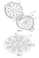
- FIG. 3shows a sensor package according to one embodiment for use with the sensing instrument of FIG. 2 .
- FIG. 4 ais a test sensor according to one embodiment using the coded auto-calibration circuit or label of FIG. 5 .
- FIG. 4 bis a side view of the test sensor of FIG. 4 a.
- FIG. 5is a cross-sectional view of a test sensor according to one embodiment.
- FIG. 6 ais a side view of an optical test sensor according to one embodiment.
- FIG. 6 bis a cross-sectional view of an optical test sensor according to one embodiment.
- FIG. 7is an isometric view of an instrument or meter for receiving a test sensor.
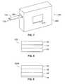
- FIG. 8shows a side view of an auto-calibrated circuit or label according to one embodiment.
- FIG. 9shows a side view of an auto-calibrated circuit or label according to another embodiment.
- FIG. 10shows a top view of a portion of a test sensor including a blank auto-calibrated circuit or label according to one embodiment.
- FIG. 11 ashows a coded or patterned auto-calibration circuit or label according to one embodiment using the blank of FIG. 10 .
- FIG. 11 bshows a coded or patterned auto-calibration circuit or label according to another embodiment using the blank of FIG. 10 .
- FIG. 11 cshows a coded or patterned auto-calibration circuit or label according to a further embodiment using the blank of FIG. 10 .
- An instrument or meterin one embodiment uses a test sensor adapted to receive a fluid sample to be analyzed, and a processor adapted to perform a predefined test sequence for measuring a predefined parameter value.
- a memoryis coupled to the processor for storing predefined parameter data values.
- Calibration information associated with the test sensormay be read by the processor before the fluid sample to be measured is received.
- Calibration informationmay be read by the processor after the fluid sample to be measured is received, but not after the information directed to the analyte has been displayed to the user.
- Calibration informationis used in measuring the predefined parameter data value to compensate for different characteristics of test sensors, which can vary on a batch-to-batch basis. Variations of this process will be apparent to those of ordinary skill in the art from the teachings disclosed herein, including but not limited to, the drawings.
- the calibration information referred to hereinmay be any information that is used by a meter or instrument to calibrate.
- the calibration informationmay be a program auto-calibration number that relates to a slope, intercept and sensitivity to common interferants of calibration lines for the test-sensor lot or batch.
- the present inventionmay define additional information that has value to the consumer.
- the present inventionhas an unexpectedly large amount of information that may be transferred from a test sensor or a test-sensor package to the instrument or meter.
- the test sensor or test-sensor packagemay provide expansion capability for future products such as, for example, when the test-sensor chemistries are modified. It is contemplated that other modifications may be implemented.
- additional featuresmay be added. For example, information such as market or country information, expiration dates and types of analytes may be transferred from the test sensor or the test-sensor package to the instrument or meter.
- the expiration datesmay be programmed in different intervals such as, for example, every 2 or 3 months.
- the expiration datemay be used in combination with the date and time of the meter to provide a small, age-related or stress-related correction so as to assist in correcting for an average stability drift.
- the informationmay also include detecting counterfeit sensors.
- FIGS. 1-3an instrument or meter 10 is illustrated in one embodiment.
- the inside of the instrument 10is shown in the absence of a test-sensor package.
- One example of a test-sensor package(sensor package 12 ) is separately illustrated in FIG. 3 .
- a base member 14 of the instrument 10supports an auto-calibration plate 16 .
- the instrument 10also includes an auto-calibration reading device 18 that is adapted to read an auto-calibration label or circuit.
- the auto-calibration circuit or labelmay be read, for example, by optical methods or via capacitance methods.
- the sensor package 12 of FIG. 3includes an auto-calibration circuit or label 120 and a plurality of test sensors 22 .
- the plurality of test sensors 22is used to determine information related to an analyte (e.g., analyte concentrations).
- Analytes that may be measuredinclude glucose, lipid profiles (e.g., cholesterol, triglycerides, LDL and HDL), microalbumin, hemoglobin A1 c , fructose, lactate, or bilirubin. It is contemplated that other analyte concentrations may be determined.
- the analytesmay be in, for example, a whole blood sample, a blood serum sample, a blood plasma sample, other body fluids like ISF (interstitial fluid) and urine, and non-body fluids.
- ISFinterstitial fluid
- the plurality of sensors 22typically has the same calibration characteristics such that calibrating the instrument 10 for one of the sensors 22 is effective to calibrate the instrument 10 for each of the plurality of sensors 22 in that particular package 12 .
- the plurality of test sensors 22includes an appropriately selected enzyme to react with the desired analyte or analytes to be tested.
- An enzyme that may be used to react with glucoseis glucose oxidase. It is contemplated that other enzymes may be used to react with glucose such as glucose dehydrogenase. It is contemplated that other enzymes may be used to react with another analytes.
- Calibration information or codes assigned for use in the clinical-value computations to compensate for manufacturing variations between sensor lotsare encoded on the auto-calibration circuit or label 120 in this embodiment.
- the auto-calibration circuit or label 120is used to automate the process of transferring calibration information (e.g., the lot specific reagent calibration information for the plurality of test sensors 22 ).
- the auto-calibration reading device 18electrically couples with the auto-calibration circuit or label 120 when a cover 30 of the instrument 10 is closed and the circuit or label 120 is present.
- the auto-calibration circuit or label 120will be discussed in detail below.
- an analyte concentration of a fluid sampleis determined using electrical current readings and at least one equation.
- equation constantsare identified using the calibration information or codes from the auto-calibration circuit or label 120 . These constants may be identified by, for example, (a) using an algorithm to calculate the equation constants or (b) retrieving the equation constants from a lookup table for a particular predefined calibration code that is read from the auto-calibration circuit or label 120 .
- the plurality of test sensors 22is arranged around the auto-calibration circuit or label 120 and extends radially from the area containing the circuit or label 120 .
- the sensors 22 of FIG. 3are stored in individual cavities or blisters 24 .
- the sensor cavities or blisters 24extend toward a peripheral edge of the sensor package 12 .
- each sensor cavity 24accommodates one of the test sensors 22 .
- the sensor package 12 of FIG. 3is generally circular in shape with the sensor cavities 24 extending from near the outer peripheral edge toward and spaced apart from the center of the sensor package 12 . It is contemplated, however, that the sensor package may be of different shapes then depicted in FIG. 3 . For example, the sensor package may be a square, rectangle, other polygonal shapes, or non-polygonal shapes including oval.
- the circuit or labelmay be used on a single test-sensor system in another embodiment.
- the circuit or labelfunctions in a similar manner except that the circuit or label is located on the test sensor itself as opposed to the sensor package that contains the test sensors.
- FIG. 4 adepicts a test sensor 100 that includes the auto-calibration circuit or label 120 that will be discussed in more detail below.
- the test sensor 100is adapted to receive a fluid sample and is analyzed using an instrument or meter.
- the test sensors described hereinmay be electrochemical test sensors.
- the metermay have optical, electrochemical or mechanical aspects so as to detect the calibration information and electrochemical aspects to determine the analyte concentration of the fluid sample.
- FIGS. 4 a , 4 bdepict the test sensor 100 including a base 110 , a channel (e.g., capillary channel), and a plurality of electrodes 114 and 116 .
- the base and a second layere.g., a lid
- assist in forming a channele.g., a capillary channel).
- a region 118shows an area that defines the capillary channel (e.g., after a lid is placed over the base 110 ).
- the plurality of electrodes of FIG. 4 aincludes a counter electrode 114 and a working (measuring) electrode 116 .
- the electrochemical test sensormay also contain at least three electrodes, such as a working electrode, an auxiliary or counter electrode, a trigger electrode, underfill detection electrode, or a hematocrit electrode.
- the electrodes 114 , 116are coupled to a plurality of conductive leads 120 a , 120 b , which, in the illustrated embodiment, terminate with a larger area designated as test-sensor contacts 122 a , 122 b .
- the capillary channelis generally located in a fluid-receiving area 124 . It is contemplated that other electrochemical test sensors may be employed.
- the fluid-receiving area 124includes at least one reagent for converting the analyte of interest (e.g., glucose) in the fluid sample (e.g., blood) into a chemical species that is electrochemically measurable, in terms of the electrical current it produces, by the components of the electrode pattern.
- the reagenttypically contains an enzyme such as, for example, glucose oxidase, which reacts with the analyte and with an electron acceptor such as a ferricyanide salt to produce an electrochemically measurable species that can be detected by the electrodes. It is contemplated that other enzymes may be used to react with glucose such as glucose dehydrogenase. If the concentration of another analyte is to be determined, an appropriate enzyme is selected to react with the analyte.
- an enzymesuch as, for example, glucose oxidase, which reacts with the analyte and with an electron acceptor such as a ferricyanide salt to produce an electrochemically measurable species that can be
- a fluid sample(e.g., blood) may be applied to the fluid-receiving area 124 .
- the fluid samplereacts with the at least one reagent. After reacting with the reagent and in conjunction with the plurality of electrodes, the fluid sample produces electrical signals that assist in determining the analyte concentration.
- the conductive leads 120 a , 120 bcarry the electrical signal back toward a second opposing end 126 of the test sensor 100 where the test-sensor contacts 122 a , 122 b transfer the electrical signals into the meter.
- the test sensor 100 of FIG. 4 afurther includes a lid 130 and a spacer 140 .
- the base 110 , the lid 130 , and the spacer 140may be made from a variety of materials such as polymeric materials.
- Non-limiting examples of polymeric materials that may be used to form the base 110 , the lid 130 , and the spacer 140include polycarbonate, polyethylene terephthalate (PET), polyethylene naphthalate (PEN), polyimide, and combinations thereof. It is contemplated that other materials may be used in forming the base 110 , lid 130 , and/or spacer 140 .
- the base 110 , the spacer 140 , and the lid 130are attached by, for example, an adhesive or heat sealing.
- the fluid-receiving area 124is formed.
- the fluid-receiving area 124provides a flow path for introducing the fluid sample into the test sensor 100 .
- the fluid-receiving area 124is formed at a first end or testing end 128 of the test sensor 100 .
- test sensorsmay be formed with a base and a lid in the absence of a spacer.
- a lidmay be formed with a convex opening that is adapted to receive a fluid.
- FIG. 5A non-limiting example of such a test sensor is shown in FIG. 5 .
- a test sensor 150includes a base 152 and a lid 154 .
- a fluid-receiving area 158is formed that is adapted to receive fluid for testing.
- test sensors of the embodiments described hereinmay be optical test sensors.
- Optical test sensor systemsmay use techniques such as, for example, transmission spectroscopy, diffuse reflectance, or fluorescence spectroscopy for measuring the analyte concentration.
- An indicator reagent system and an analyte in a sample of body fluidare reacted to produce a chromatic reaction, as the reaction between the reagent and analyte causes the sample to change color.
- the degree of color changeis indicative of the analyte concentration in the body fluid.
- the color change of the sampleis evaluated to measure the absorbance level of the transmitted light.
- Non-limiting example of optical test sensorsare shown in FIGS. 6 a , 6 b .
- the base 210 , the spacer 240 , and the lid 230are attached by, for example, an adhesive or heat sealing.
- a fluid-receiving area 224is formed.
- the fluid-receiving area 224provides a flow path for introducing the fluid sample into the test sensor 200 .
- the fluid-receiving area 224is formed at a first end or testing end 228 of the test sensor 200 .
- the optical test sensorsmay be formed with a base and a lid in the absence of a spacer.
- a lidmay be formed with a convex opening that is adapted to receive a fluid.
- FIG. 6 bA non-limiting example of such an optical test sensor is shown in FIG. 6 b .
- an optical test sensor 250includes a base 252 and a lid 254 .
- a fluid-receiving area 258is formed that is adapted to receive fluid for testing.
- the instrumentmay include several responses to reading the auto-calibration label.
- responsesmay include the following codes: (1) correct read, (2) misread, (3) non-read, defective code, (4) non-read, missing label or circuit, and (5) read code out-of-bounds.
- a correct readindicates that the instrument or meter correctly read the calibration information.
- a misreadindicates that the instrument did not correctly read the calibration information encoded in the circuit or label.
- the circuit or labelpassed the integrity checks.
- a non-read, defective codeindicates that the instrument senses that a circuit or label is present (continuity between two or more auto-calibration pins), but the code fails one or more encoding rules (circuit integrity checks).
- a non-read, missing circuit or labelindicates that the instrument does not sense the presence of a circuit or label.
- a read code out-of-boundsindicates that the instrument senses an auto-calibration code, but the calibration information is not valid for that instrument.
- FIG. 7depicts a single test-sensor instrument or meter 260 .
- the second opposing end 126 of the test sensor 100is adapted to be placed into a test-sensor opening 264 in the instrument or meter 260 of FIG. 7 .
- the meter 260includes a housing 266 that forms the test-sensor opening 264 , which is of sufficient size to receive the second opposing end 126 of the test sensor 100 .
- the meter 260uses, for example, the appropriate program number during calculation of the analyte concentration by the meter software.
- the housing 266may comprise a display 270 (e.g., an LCD screen) that displays, for example, analyte concentrations. It is contemplated that the meter 260 may be configured to receive an optical test sensor (e.g., test sensor 200 ) and in such an embodiment, the meter would typically include an optical readhead located at or near the test-sensor opening.
- a display 270e.g., an LCD screen
- the meter 260may be configured to receive an optical test sensor (e.g., test sensor 200 ) and in such an embodiment, the meter would typically include an optical readhead located at or near the test-sensor opening.
- the meters used with the test sensorsmay include a mechanism for determining whether the test sensors are fully inserted.
- the mechanismmay be positioned, for example, in or adjacent to the test-sensor opening.
- the metermay further be adapted to report an error to a user if it detects that the test sensor is not fully inserted.
- the auto-calibration circuit or label 120is adapted to be used with a test-sensor package such as described above in FIGS. 1-3 or with test sensors such as described above in conjunction with FIGS. 4-6 .
- the auto-calibration circuit or label 120is formed and applied to a test sensor or test-sensor package by first providing a circuit or label.
- This first provided circuit or labelmay also be referred to as labelstock.
- the auto-calibration label or circuitincludes a first layer, a second layer and a lamination portion.
- the second layeris located between the first layer and the lamination portion.
- the first layerincludes polymeric material.
- the second layerincludes conductive material.
- the present inventionis advantageous in that the auto-calibration circuit or label is self-contained in that the second layer is located beneath the first layer after being applied to a test sensor or a test-sensor package.
- the second layeris protected by the first layer after being applied to the test sensor or a test-sensor package.
- no additional layeris necessary to further protect the second layer (e.g., an aluminum layer) from scratching.
- the second layeris protected and, thus, is less likely to be scratched.
- FIG. 8One non-limiting example of an auto-calibration circuit or label is shown in FIG. 8 .
- the auto-calibration circuit 120is shown in FIG. 8 .
- the auto-calibration circuit or label 120includes a first layer 40 , a second layer 50 and a lamination portion 60 .
- the lamination portionmay be in a form of a continuous layer or may be in the form of a non-continuous layer.
- the second layer 50is located between the first layer 40 and the lamination portion 60 .
- the first layeris generally transparent to the laser such that the light emitted by the laser is allowed to mark the second layer.
- the first layerin one aspect includes polyethylene terephthalate (PET).
- PETpolyethylene terephthalate
- Polyethylene terephthalateis desirable because of its ability to protect the second layer.
- Polyethylene terephthalateis also desirable because of its transparency that allows the light emitted by the laser to mark the second layer, resulting in the formation of an auto-calibration pattern in the second layer.
- Other advantages of polyethylene terephthalateinclude its durability and economical considerations.
- One modified type of PET that may be usedis glycol-modified polyethylene terephthalate (PETG). It is also contemplated that other polymeric materials may be used to form the first layer.
- polymeric materialsthat may be used in forming the first layer include polycarbonate, polyvinyl chloride (PVC), polystyrene and polymethylmethacrylate and combinations thereof including PET. It is contemplated that other materials may be used in forming the first layer.
- the first layeris desirably a clear or translucent material such that light can pass therethrough.
- an optical readheadmay determine the auto-calibration pattern formed from the second layer without removing the first layer.
- the first layermay not necessarily need to be a clear or translucent material if a capacitance method is used.
- the thickness of the first layeris generally from about 0.5 to about 15 mils and, more typically, from about 1 to about 5 mils. It is contemplated that the thickness of the first layer may be outside these ranges.
- the second layeris a conductive layer. Portions of the second layer are ablated using a laser such that an auto-calibration pattern is formed in the second layer that conveys auto-calibration information to a meter or an instrument.
- the second layerin one aspect includes aluminum. Aluminum is desirable because of its ability to be distinguished after being marked by a laser. Aluminum is also desirable to be used in forming the auto-calibration pattern because of its cost considerations at the present time.
- the first layermay be a non-metallic layer such as a carbon layer.
- the thickness of the second layeris generally from about 25 to about 500 nm and, more typically, from about 25 to about 250 nm. It is contemplated that the thickness of the second layer may be outside of these ranges.
- the first layer and the second layermay be attached several methods.
- the conductive second layeris formed by sputtered conductive metal on the first layer.
- conductive metalmay be flashed or plated onto the first layer.
- the second layer and the first layermay be formed by coextrusion or lamination. It is contemplated that other attaching methods may be used to attach the first layer and the second layer.
- a combination of the second layer and the first layermay be commercially purchased from a company such as Sheldahl of Northfield, Minn. or 3M of St. Paul, Minn.
- the lamination portionis adapted to attach the label or circuit to a test sensor or test-sensor package.
- the laminated portionmay be a pressure-sensitive adhesive (PSA). It is contemplated that other adhesives may be used to form the laminated portion such as heat-activated polyurethanes, vinyl acetate-ethylene (VAE), and starch-based adhesives. It is contemplated that other adhesives may be used to form the lamination portion.
- PSApressure-sensitive adhesive
- VAEvinyl acetate-ethylene
- starch-based adhesivesIt is contemplated that other adhesives may be used to form the lamination portion.
- the lamination portionis selected to provide sufficient adhesion between the second layer and the surface of the test sensor or the test-sensor package.
- the lamination portionmay be in a form of a continuous layer or may be in the form of a non-continuous layer.
- the thickness of the lamination portionis generally from about 0.5 to about 3 mils and, more typically, from about 0.75 to about 2 mils. It is contemplated that the thickness of the laminated portion may be outside of these ranges.
- the material for the laminationmay be commercially purchased from a company such as 3M of St. Paul, Minn.
- the thickness of the auto-calibration circuit or labelmay vary.
- the thickness of the auto-calibration circuit or labelis generally from about 1 to about 20 mils and, more typically, from about 2 to about 10 mils. It is contemplated that the thickness of the auto-calibration circuit or label may be outside of these ranges.
- an auto-calibration circuit 120 bincludes the first layer 40 , the second layer 50 , the lamination portion 60 and a release liner 70 .
- the second layer 50is located between the first layer 40 and the lamination portion 60 .
- the lamination portion 60is located between the second layer 50 and the release liner 70 .
- the release liner 70is located directly adjacent to the lamination portion 60 in this configuration.
- a release linerprevents or inhibits the lamination portion from attaching to another surface before being applied to the test sensor or the test-sensor package.
- the release linermay be formed from several different types of materials, but is typically formed from polymeric materials (e.g., polyethylene terephthalate (PET)) or paper. Release liners are commercially available from 3M of St. Paul, Minn. and International Paper of Memphis, Tenn.
- the test sensor 300includes the auto-calibration circuit or label 120 c .
- the auto-calibration circuit or label 120 cincludes a plurality of potential metallized areas 310 a - 1 in a 3 ⁇ 4 array.
- the metallized areas 310 a - 1are located at an end 302 of the test sensor 300 .
- the presence of a metallized area 310signifies a logical “1” and the absence of a metallized area signifies a logical “0” (also referred to as background area).
- a logical “1”would not be ablated, whereas all of the logical “0” would be ablated and removed.
- the logical “1”swould appear as conductive or reflective islands surrounded by a non-conductive sea (background area).
- a logical “1”would be ablated and removed, whereas all of the logical “0” (background area) would not be ablated.
- the logical “1”swould appear as non-conductive islands surrounded by a conductive or reflective sea.
- FIGS. 11 a - 11 cnon-limiting examples of conductive areas being formed on a second layer of the test sensor 300 are shown.
- a test sensor 300 ainitially included the plurality of conductive areas 310 . All of the conductive areas 310 a - 1 of test sensor 300 a have been ablated except conductive area 310 h . Thus, only conductive area 310 h remains conductive and reflective in FIG. 11 a . In the areas where the second layer has been ablated, they are no longer reflective and, thus, the marked non-reflective areas are easily distinguishable from the reflective, non-marked areas. Thus, in this example, the conductive area 310 h is easily distinguishable from the other non-conductive areas.
- FIG. 11 bshows another example of a test sensor (test sensor 300 b ). All of the conductive areas 310 have been ablated except conductive areas 310 d , 310 h , 301 i and 310 k . Thus, these four conductive areas remain conductive and reflective in the embodiment of FIG. 11 b .
- FIG. 11 cshows another example of a test sensor (test sensor 300 c ) in which several conductive areas 310 have been ablated.
- the test sensor 300 cincludes conductive areas 310 a - e , 310 hi and 310 i that have not been ablated. Conductive areas 310 a - e , 310 h and 310 i remain conductive and reflective.
- Each of the test sensors 300 a , 300 b , 300 cforms a different auto-calibration pattern that will be read by the meter or instrument.
- arrays and/or numbers of conductive areasmay be used to form the auto-calibration pattern with the second layer other than that depicted in FIGS. 10 , 11 a - 11 c .
- different arraysmay be used such as a 4 ⁇ 4 array, 3 ⁇ 5 array or a 3 ⁇ 3 array.
- shape and/or size of the conductive areas or padsmay differ from that shown in FIGS. 10 , 11 a - 11 c .
- the dimension of the conductive areasmay be about 1.8 mm ⁇ about 2.4 mm.
- the shapes of the conductive areasare typically polygonal in shape (e.g., rectangular or square), but may be non-polygonal in shape.
- the auto-calibration circuit or labelmay be formed according to the following method.
- a label or circuitis provided in which the label or circuit includes a first layer, a second layer and a lamination portion.
- the second layeris located between the first layer and the lamination portion.
- the first layeris typically formed of polymeric material, while the second layer includes conductive material.
- the circuit or labelis applied to the test sensor via the lamination portion. After the circuit or label is applied to the test sensor, portions of the second layer are ablated using a laser to form an auto-calibration pattern on the label or circuit.
- the patternis adapted to be utilized by a meter or instrument to auto-calibrate.
- the circuit or labelis typically applied to the test sensor in a web form.
- a web of the circuit or labelis applied to a web of test sensor.
- this processis advantageous because it involves one lamination act by applying the label or circuit to the test sensor or the test-sensor package and can use only one first layer to protect the second layer and one lamination portion.
- Thisimproves processes that, for example, remove and reapply the same or similar layers, which increase the material cost (extra layer and adhesive) as well as incurring additional processing costs.
- a first layeris desirable to protect the second layer from scratching, processes that remove this first layer during ablation reapply another first layer after ablation for protection resulting in the above-described costs.
- Both first layer materialse.g., PET
- laminating materialse.g., pressure-sensitive materials
- the ablation of the second layercould be performed in the present invention since the first layer is located between the second layer and the laser.
- the ablated materialsare usually vaporized and are removed with the exhaust as a top or uppermost layer—not a layer located beneath another layer.
- the second layeris ablated with the first layer being located and remaining between the laser and the second layer. While not being bound by theory, it was discovered from microscopic examination of the ablated layer (second layer) that the previously continuous, conductive second layer (using aluminum) had been converted to isolated globules of aluminum. Thus, the ablated areas of the aluminum second layer had small aluminum globules without bulk conductivity because the globules were not in contact with one another. The first layer remains during the ablation process since it is generally transparent to the light.
- a test sensormay include a section that includes at least a first layer and a second layer that will be formed into an auto-calibration circuit.
- the sectionis formed with the test sensor as opposed to be attached in a later processing step. It is contemplated that many methods of forming such a test sensor may be used.
- a tie layermay be used to assist in forming the area that will be used for auto-calibration.
- the tie layermay be a polyolefin layer such as, for example, polypropylene.
- the second layeris located between the first layer and the tie layer.
- the auto-calibration circuitfunctions in the same manner as described above with the auto-calibration circuit or label 120 .
- the test-sensor packagingmay include a section that includes at least a first layer and a second layer that will be formed into an auto-calibration circuit.
- the sectionis formed with the test-sensor packaging as opposed to be attached in a later processing step. It is contemplated that many methods of forming such a test-sensor packaging may be used.
- a tie layermay be used to assist in forming the area that will be used for auto-calibration.
- the tie layermay be a polyolefin layer such as, for example, polypropylene.
- the second layeris located between the first layer and the tie layer.
- the auto-calibration circuitfunctions in the same manner as described above with the auto-calibration circuit or label 120 .
- a lasercreates the auto-calibration pattern from the second layer to form an auto-calibration circuit or label.
- lasersThere are many different types of lasers that may be used in creating the auto-calibration pattern.
- a laser that may be used in ablating portions of the second layeris a Trumpf VectorMark Compact VMC 5 Y-VO 4 laser.
- this lasermay be operated at different power conditions. For example, using a 220 nm thick aluminum second layer, the Trumpf VMC 5 Y-VO 4 laser may be operated using 90% power, a marking speed of 3000 mm/s and a frequency of 100 kHz. It is contemplated that using a thinner second layer, the Trumpf VMC 5 Y-VO 4 laser may be operated at a reduced power level such as 60% power.
- Another laser that may be used in the present inventionis a solid-state laser such as an yttrium-based laser.
- yttrium-based lasersthat are commercially available are Rofin DY-HP Series, Telesis ECLIPSE® TLM, or Telesis ZENITH® Series. It is contemplated that other yttrium-based lasers may be used.
- a further type of laser that may be usedis an Excimer laser.
- Excimer lasersuse reactive gases, such as chlorine and fluorine, that are mixed with inert gases such as argon, krypton or xenon. To obtain optimum ablation, the wavelength may need to be matched to the selected metal of the conductive layer.
- An example of an Excimer laser that is commercially availableis Lambda Physik F 2 Series. It is contemplated that other Excimer lasers may be used. It is also contemplated that other lasers may be used in forming the auto-calibration circuits or labels other than those discussed above in the specific examples above.
- the patternmay be created using a mask and a laser such as, for example, an Excimer laser or an yttrium-based laser. It is contemplated that various masks may work in conjunction with the laser in forming the auto-calibration circuit or label.
- a maskis a chrome-on-glass mask in which the beam of light is only allowed to pass through selected areas to form the auto-calibration circuit or label.
- the patternmay be created using direct writing of the lines.
- the laser beam of lightis moved so as to form the desired pattern.
- other patternsmay be created using direct writing of the lines.
- Lasers that produce a beam of energy capable of removing portions of the second layer and that can be moved to form a patternmay be used in this method.
- Non-limiting examples of such lasersare yttrium-based lasers such as yttrium aluminum garnet (YAG) lasers or Y-VO 4 lasers.
- lasersare desirable because they are adapted to work in tighter spaces.
- these laser methodscan produce spaces between adjacent conductive areas of from about 25 to about 250 microns, which allow for the possibility of tighter tolerances and/or a smaller auto-calibration area.
- the auto-calibration patternmay be read optically in one method.
- areas in which the second layer has been ablatedare no longer reflective and, thus, the ablated, non-reflective areas are easily distinguishable from the reflective, non-ablated areas.
- an auto-calibration patternis formed therein.
- a meter or instrumentincludes an optical readhead that optically reads the reflective and non-reflective areas of the second layer.
- An optical readhead that may be usedincludes a light source, detector and collection optics if required.
- the auto-calibration patternmay be read by capacitance measurements.
- areas in which the second layer has been ablateddiffer in capacitance measurements from those non-ablated areas of the second layer.
- a meter or instrumentincludes components for measuring capacitance.
- One example for measuring capacitanceis a capacitance-to-digital converter.
- a non-limiting example of a capacitance-to-digital converteris the commercial available Analog Devices AD7147 CDC capacitance-to-digital converter. It is contemplated that other capacitance-measuring devices may be used in this method.
- the auto-calibration circuits or labelsmay be used with instruments other than instrument or meter 10 , 260 depicted in FIGS. 1 , 2 and 7 .
- the auto-calibration circuits or labelsmay also be used in other type of sensor packs than sensor package 12 or test sensor 100 .
- the auto-calibration circuits or labelsmay be used in sensor packages such as a cartridge with a stacked plurality of test sensors or a drum-type sensor package.
Landscapes
- Health & Medical Sciences (AREA)
- Life Sciences & Earth Sciences (AREA)
- Engineering & Computer Science (AREA)
- Physics & Mathematics (AREA)
- Biomedical Technology (AREA)
- General Health & Medical Sciences (AREA)
- Molecular Biology (AREA)
- Biophysics (AREA)
- Optics & Photonics (AREA)
- Pathology (AREA)
- Veterinary Medicine (AREA)
- Chemical & Material Sciences (AREA)
- Surgery (AREA)
- Animal Behavior & Ethology (AREA)
- Medical Informatics (AREA)
- Public Health (AREA)
- Heart & Thoracic Surgery (AREA)
- Hematology (AREA)
- Urology & Nephrology (AREA)
- Emergency Medicine (AREA)
- Food Science & Technology (AREA)
- Medicinal Chemistry (AREA)
- Analytical Chemistry (AREA)
- Biochemistry (AREA)
- General Physics & Mathematics (AREA)
- Immunology (AREA)
- Investigating Or Analysing Materials By Optical Means (AREA)
- Investigating Or Analysing Biological Materials (AREA)
Abstract
Description
Claims (25)
Priority Applications (1)
| Application Number | Priority Date | Filing Date | Title |
|---|---|---|---|
| US12/551,654US8424763B2 (en) | 2008-10-07 | 2009-09-01 | Method of forming an auto-calibration circuit or label |
Applications Claiming Priority (2)
| Application Number | Priority Date | Filing Date | Title |
|---|---|---|---|
| US19539308P | 2008-10-07 | 2008-10-07 | |
| US12/551,654US8424763B2 (en) | 2008-10-07 | 2009-09-01 | Method of forming an auto-calibration circuit or label |
Publications (2)
| Publication Number | Publication Date |
|---|---|
| US20100084466A1 US20100084466A1 (en) | 2010-04-08 |
| US8424763B2true US8424763B2 (en) | 2013-04-23 |
Family
ID=41445478
Family Applications (1)
| Application Number | Title | Priority Date | Filing Date |
|---|---|---|---|
| US12/551,654Expired - Fee RelatedUS8424763B2 (en) | 2008-10-07 | 2009-09-01 | Method of forming an auto-calibration circuit or label |
Country Status (3)
| Country | Link |
|---|---|
| US (1) | US8424763B2 (en) |
| EP (1) | EP2342560B1 (en) |
| WO (1) | WO2010042435A1 (en) |
Cited By (7)
| Publication number | Priority date | Publication date | Assignee | Title |
|---|---|---|---|---|
| US9373007B2 (en) | 2013-11-21 | 2016-06-21 | Analog Devices Global | Low-cost capacitive sensing decoder |
| US9506890B2 (en) | 2014-12-16 | 2016-11-29 | Eastman Chemical Company | Physical vapor deposited biosensor components |
| US10330666B2 (en) | 2014-03-07 | 2019-06-25 | Ascensia Diabetes Care Holdings Ag | Biosensor calibration coding systems and methods |
| US11624723B2 (en) | 2016-09-16 | 2023-04-11 | Eastman Chemical Company | Biosensor electrodes prepared by physical vapor deposition |
| US11630075B2 (en) | 2016-09-16 | 2023-04-18 | Eastman Chemical Company | Biosensor electrodes prepared by physical vapor deposition |
| US11835481B2 (en) | 2016-06-15 | 2023-12-05 | Eastman Chemical Company | Physical vapor deposited biosensor components |
| US11881549B2 (en) | 2017-06-22 | 2024-01-23 | Eastman Chemical Company | Physical vapor deposited electrode for electrochemical sensors |
Families Citing this family (7)
| Publication number | Priority date | Publication date | Assignee | Title |
|---|---|---|---|---|
| US8789756B2 (en) | 2006-02-25 | 2014-07-29 | Roche Diagnostics Operations, Inc. | Test element coding apparatuses, systems and methods |
| WO2008076212A1 (en)* | 2006-12-13 | 2008-06-26 | Bayer Healthcare Llc | Biosensor with coded information and method for manufacturing the same |
| RU2010108229A (en)* | 2007-08-06 | 2011-09-20 | БАЙЕР ХЕЛТКЭА ЭлЭлСи (US) | SYSTEM AND METHOD FOR AUTOMATIC CALIBRATION |
| US8906209B2 (en) | 2007-12-10 | 2014-12-09 | Bayer Healthcare Llc | Auto-calibrating test sensor and method of making the same |
| US20090205399A1 (en)* | 2008-02-15 | 2009-08-20 | Bayer Healthcare, Llc | Auto-calibrating test sensors |
| US8888973B2 (en) | 2011-07-29 | 2014-11-18 | Roche Diagnostics Operations, Inc. | Encoded biosensors and methods of manufacture and use thereof |
| US9754708B2 (en) | 2011-07-29 | 2017-09-05 | Roche Diabetes Care, Inc. | Encoded biosensors and methods of manufacture and use thereof |
Citations (98)
| Publication number | Priority date | Publication date | Assignee | Title |
|---|---|---|---|---|
| US4510383A (en) | 1981-09-18 | 1985-04-09 | Boehringer Mannheim Gmbh | Device for the optical identification of a coding on a diagnostic test strip |
| US4714847A (en) | 1984-12-21 | 1987-12-22 | General Electric Company | Advanced piezoeceramic power switching devices employing protective gastight enclosure and method of manufacture |
| US4847181A (en) | 1986-08-08 | 1989-07-11 | Mazda Motor Corporation | Laser marking method |
| US4929426A (en) | 1987-11-02 | 1990-05-29 | Biologix, Inc. | Portable blood chemistry measuring apparatus |
| US4940945A (en) | 1987-11-02 | 1990-07-10 | Biologix Inc. | Interface circuit for use in a portable blood chemistry measuring apparatus |
| US5194393A (en) | 1989-11-21 | 1993-03-16 | Bayar Aktiengesellschaft | Optical biosensor and method of use |
| US5281395A (en) | 1990-12-27 | 1994-01-25 | Boehringer Manheim Gmbh | Test carrier analysis system |
| US5379214A (en) | 1991-02-27 | 1995-01-03 | Boehringer Mannheim Corporation | Method for reading the concentration of a medically significant component of a biological fluid from a test strip |
| US5443080A (en) | 1993-12-22 | 1995-08-22 | Americate Transtech, Inc. | Integrated system for biological fluid constituent analysis |
| US5445967A (en) | 1991-05-31 | 1995-08-29 | Boehringer Mannheim Gmbh | Method for analyzing a component of a liquid sample |
| US5489414A (en) | 1993-04-23 | 1996-02-06 | Boehringer Mannheim, Gmbh | System for analyzing compounds contained in liquid samples |
| US5510266A (en) | 1995-05-05 | 1996-04-23 | Bayer Corporation | Method and apparatus of handling multiple sensors in a glucose monitoring instrument system |
| US5518689A (en) | 1995-09-05 | 1996-05-21 | Bayer Corporation | Diffused light reflectance readhead |
| US5575403A (en) | 1995-01-13 | 1996-11-19 | Bayer Corporation | Dispensing instrument for fluid monitoring sensors |
| US5580794A (en) | 1993-08-24 | 1996-12-03 | Metrika Laboratories, Inc. | Disposable electronic assay device |
| US5597532A (en) | 1994-10-20 | 1997-01-28 | Connolly; James | Apparatus for determining substances contained in a body fluid |
| US5611999A (en) | 1995-09-05 | 1997-03-18 | Bayer Corporation | Diffused light reflectance readhead |
| EP0840122A2 (en) | 1996-10-30 | 1998-05-06 | Bayer Corporation | Method and apparatus for calibrating a sensor element |
| US5780304A (en) | 1994-09-08 | 1998-07-14 | Lifescan, Inc. | Method and apparatus for analyte detection having on-strip standard |
| US5795543A (en) | 1994-11-14 | 1998-08-18 | Advanced Care Products | Disposable electronic diagnostic instrument |
| US5830133A (en) | 1989-09-18 | 1998-11-03 | Minnesota Mining And Manufacturing Company | Characterizing biological matter in a dynamic condition using near infrared spectroscopy |
| US5837546A (en) | 1993-08-24 | 1998-11-17 | Metrika, Inc. | Electronic assay device and method |
| US5866349A (en) | 1989-04-25 | 1999-02-02 | Lilja; Jan Evert | Method for determination of glucose in whole blood and cuvette and photometer for carrying out said method |
| US5945341A (en) | 1996-10-21 | 1999-08-31 | Bayer Corporation | System for the optical identification of coding on a diagnostic test strip |
| US5962215A (en) | 1996-04-05 | 1999-10-05 | Mercury Diagnostics, Inc. | Methods for testing the concentration of an analyte in a body fluid |
| JP2000019147A (en) | 1998-07-01 | 2000-01-21 | Nok Corp | Reaction product measuring device |
| US6168957B1 (en) | 1997-06-25 | 2001-01-02 | Lifescan, Inc. | Diagnostic test strip having on-strip calibration |
| US6280891B2 (en) | 1994-05-04 | 2001-08-28 | Hologram Industries S.A. | Multi-layer assembly and method for marking articles and resulting marked articles |
| US20010023324A1 (en) | 1997-11-03 | 2001-09-20 | Allan Pronovost | Glucose detector and method for diagnosing diabetes |
| EP1152239A1 (en) | 1999-11-15 | 2001-11-07 | Matsushita Electric Industrial Co., Ltd. | Biosensor, method of forming thin-film electrode, and method and apparatus for quantitative determination |
| US20010045355A1 (en) | 2000-03-09 | 2001-11-29 | Clinical Analysis Corporation | Medical diagnostic system |
| US6335203B1 (en) | 1994-09-08 | 2002-01-01 | Lifescan, Inc. | Optically readable strip for analyte detection having on-strip orientation index |
| US6377894B1 (en) | 1998-11-30 | 2002-04-23 | Abbott Laboratories | Analyte test instrument having improved calibration and communication processes |
| US20020059030A1 (en) | 2000-07-17 | 2002-05-16 | Otworth Michael J. | Method and apparatus for the processing of remotely collected electronic information characterizing properties of biological entities |
| US6441898B1 (en) | 1999-09-15 | 2002-08-27 | Ernst Markart | Test strip and measurement device for its evaluation |
| US20020133080A1 (en) | 2001-02-06 | 2002-09-19 | William Apruzzese | Layered calibration standard for tissue sampling |
| US20020137059A1 (en) | 2001-01-26 | 2002-09-26 | Lei Wu | Microdevice containing photorecognizable coding patterns and methods of using and producing the same thereof |
| EP1256798A1 (en) | 2000-11-30 | 2002-11-13 | Matsushita Electric Industrial Co., Ltd. | Biosensor, measuring instrument for biosensor, and method of quantifying substrate |
| US6485437B1 (en) | 1998-02-24 | 2002-11-26 | Robert Tapper | Sensor controlled analysis and therapeutic delivery system |
| US20030013941A1 (en) | 1997-04-25 | 2003-01-16 | Beth Israel Deaconess Medical Center | Surgical Retractor |
| US20030062262A1 (en) | 2001-08-22 | 2003-04-03 | Sohrab Mansouri | Automated system for continuously and automatically calibrating electrochemical sensors |
| US20030098233A1 (en) | 2001-10-10 | 2003-05-29 | Kermani Mahyar Z. | Determination of sample volume adequacy in biosensor devices |
| US20030109777A1 (en) | 2001-12-07 | 2003-06-12 | Kloepfer Hans G. | Consolidated body fluid testing device and method |
| US6599406B1 (en) | 1997-07-22 | 2003-07-29 | Kyoto Daiichi Kagaku Co., Ltd. | Concentration measuring apparatus, test strip for the concentration measuring apparatus, biosensor system and method for forming terminal on the test strip |
| US20030157726A1 (en) | 2000-08-31 | 2003-08-21 | Uwe Blum | Method for improving the measurement accuracy of sensors, especially bio-sensors, which are used to determine the signals of fluorescence radiation |
| US20030191415A1 (en) | 2001-03-29 | 2003-10-09 | Piet Moerman | Integrated sample testing meter |
| US20030207441A1 (en) | 2002-05-01 | 2003-11-06 | Eyster Curt R. | Devices and methods for analyte concentration determination |
| US20030207454A1 (en) | 2002-05-01 | 2003-11-06 | Eyster Curt R. | Devices and methods for analyte concentration determination |
| US6645359B1 (en) | 2000-10-06 | 2003-11-11 | Roche Diagnostics Corporation | Biosensor |
| US6662439B1 (en) | 1999-10-04 | 2003-12-16 | Roche Diagnostics Corporation | Laser defined features for patterned laminates and electrodes |
| US20040012676A1 (en) | 2002-03-15 | 2004-01-22 | Affymetrix, Inc., A Corporation Organized Under The Laws Of Delaware | System, method, and product for scanning of biological materials |
| US20040019653A1 (en) | 2002-07-26 | 2004-01-29 | Philippe Debaty | Context-aware client system |
| US20040019686A1 (en) | 2002-07-24 | 2004-01-29 | Hitachi, Ltd. | Switching node apparatus for storage network and method of accessing remote storage apparatus |
| US20040048172A1 (en)* | 2000-10-12 | 2004-03-11 | Sven Fischer | Film which can be inscribed by a laser beam |
| US20040047764A1 (en) | 2002-09-10 | 2004-03-11 | Bayer Healthcare Llc | Auto-calibration label and apparatus comprising same |
| US20040106858A1 (en) | 1998-04-30 | 2004-06-03 | Therasense, Inc. | Analyte monitoring device and methods of use |
| EP1431758A1 (en) | 2001-09-28 | 2004-06-23 | Arkray, Inc. | Measurement instrument and concentration measurement apparatus |
| US6767440B1 (en) | 2001-04-24 | 2004-07-27 | Roche Diagnostics Corporation | Biosensor |
| US6770487B2 (en) | 2001-05-01 | 2004-08-03 | Ischemia Technologies, Inc. | Bar code readable diagnostic strip test |
| US6773671B1 (en) | 1998-11-30 | 2004-08-10 | Abbott Laboratories | Multichemistry measuring device and test strips |
| US20040156832A1 (en) | 2002-09-30 | 2004-08-12 | Centec Limited | Immunoglobulin compositions and methods |
| US20040200721A1 (en) | 2001-08-29 | 2004-10-14 | Bhullar Raghbir S. | Biosensor |
| US20040259180A1 (en) | 2003-06-20 | 2004-12-23 | Burke David W. | System and method for analyte measurement employing maximum dosing time delay |
| US20050019953A1 (en) | 2003-06-20 | 2005-01-27 | Henning Groll | System and method for coding information on a biosensor test strip |
| US20050019945A1 (en) | 2003-06-20 | 2005-01-27 | Henning Groll | System and method for coding information on a biosensor test strip |
| US20050016846A1 (en) | 2003-06-20 | 2005-01-27 | Henning Groll | System and method for coding information on a biosensor test strip |
| US20050016845A1 (en) | 2003-06-20 | 2005-01-27 | Henning Groll | System and method for coding information on a biosensor test strip |
| US20050019805A1 (en) | 2003-06-20 | 2005-01-27 | Henning Groll | System and method for coding information on a biosensor test strip |
| US20050027181A1 (en) | 2003-08-01 | 2005-02-03 | Goode Paul V. | System and methods for processing analyte sensor data |
| US20050023137A1 (en) | 2003-06-20 | 2005-02-03 | Bhullar Raghbir S. | Biosensor with multiple electrical functionalities |
| US20050076845A1 (en) | 2003-10-14 | 2005-04-14 | Langdale Dennis M. | Pet litter apparatus |
| US20050079945A1 (en) | 2003-10-08 | 2005-04-14 | Wittkopp Scott H. | Seven-speed transmission |
| US20050103624A1 (en) | 1999-10-04 | 2005-05-19 | Bhullar Raghbir S. | Biosensor and method of making |
| US20050121322A1 (en) | 1998-04-30 | 2005-06-09 | Therasense, Inc. | Analyte monitoring device and methods of use |
| US20050137471A1 (en) | 2003-12-18 | 2005-06-23 | Hans-Peter Haar | Continuous glucose monitoring device |
| US20050142033A1 (en) | 2003-11-04 | 2005-06-30 | Meso Scale Technologies, Llc. | Modular assay plates, reader systems and methods for test measurements |
| US20050154271A1 (en) | 2003-11-19 | 2005-07-14 | Andrew Rasdal | Integrated receiver for continuous analyte sensor |
| US20050161345A1 (en) | 2003-06-20 | 2005-07-28 | Henning Groll | System and method for coding information on a biosensor test strip |
| US20050196747A1 (en) | 2004-03-05 | 2005-09-08 | Matthias Stiene | Analyte test system for determining the concentration of an analyte in a physiological or aqueous fluid |
| US20050226846A1 (en) | 1999-11-03 | 2005-10-13 | Powderject Research Limited | Nucleic acid vaccine compositions having a mammalian CD80/CD86 gene promoter driving antigen expression |
| US20050279647A1 (en) | 2004-06-18 | 2005-12-22 | Terry Beaty | System and method for coding information on a biosensor test strip |
| US20060108218A1 (en) | 2001-03-05 | 2006-05-25 | Clinical Analysis Corporation | Test cell for use with medical diagnostic instrument |
| EP1666605A1 (en) | 2000-03-28 | 2006-06-07 | Diabetes Diagnostics, Inc. | Continuous process for manufacture of disposable electro-chemical sensor |
| US20060189895A1 (en) | 2003-12-31 | 2006-08-24 | Neel Gary T | Test strip container with integrated meter having strip coding capability |
| WO2006113840A2 (en)* | 2005-04-19 | 2006-10-26 | Bayer Healthcare Llc | Method of forming an auto-calibration label using a laser |
| WO2006127635A1 (en) | 2005-05-24 | 2006-11-30 | Bayer Healthcare Llc | Sensor package with an interim auto-calibration circuit |
| US20070110615A1 (en) | 2005-07-15 | 2007-05-17 | Neel Gary T | Diagnostic strip coding system and related methods of use |
| EP1475630A4 (en) | 2002-02-12 | 2007-10-24 | Arkray Inc | Measuring device and removal device for stored object |
| EP1484603A4 (en) | 2002-03-08 | 2007-11-21 | Arkray Inc | Analyzer having information recognizing function, analytic tool for use therein, and unit of analyzer and analytic tool |
| US20070273904A1 (en) | 2006-05-26 | 2007-11-29 | Lifescan Scotland, Ltd. | Method for determining a test strip calibration code for use in a meter |
| WO2008021164A2 (en) | 2006-08-14 | 2008-02-21 | Bayer Healthcare Llc | System for transferring calibration data |
| US20080081341A1 (en)* | 2006-10-03 | 2008-04-03 | Jonathan Scott Maher | Immunoassay test device and method of use |
| US20080105024A1 (en) | 2006-11-07 | 2008-05-08 | Bayer Healthcare Llc | Method of making an auto-calibrating test sensor |
| US20080199893A1 (en)* | 2004-06-23 | 2008-08-21 | Tesa Ag | Medical Biosensor By Means of Which Biological Liquids are Analyzed |
| US20090030617A1 (en)* | 2007-07-23 | 2009-01-29 | Schell Robert D | Biosensor Calibration System |
| US20090113981A1 (en) | 2007-11-06 | 2009-05-07 | Bayer Healthcare, Llc | Auto-calibrating test sensors |
| US20090125268A1 (en) | 2007-11-11 | 2009-05-14 | Bayer Healthcare Llc | Biosensor Coding System |
| EP1593961B1 (en) | 2003-02-14 | 2013-01-09 | Arkray Inc. | Analyzing tool with knob part |
- 2009
- 2009-09-01USUS12/551,654patent/US8424763B2/ennot_activeExpired - Fee Related
- 2009-10-05WOPCT/US2009/059528patent/WO2010042435A1/enactiveApplication Filing
- 2009-10-05EPEP09737500.0Apatent/EP2342560B1/enactiveActive
Patent Citations (117)
| Publication number | Priority date | Publication date | Assignee | Title |
|---|---|---|---|---|
| US4510383A (en) | 1981-09-18 | 1985-04-09 | Boehringer Mannheim Gmbh | Device for the optical identification of a coding on a diagnostic test strip |
| US4714847A (en) | 1984-12-21 | 1987-12-22 | General Electric Company | Advanced piezoeceramic power switching devices employing protective gastight enclosure and method of manufacture |
| US4847181A (en) | 1986-08-08 | 1989-07-11 | Mazda Motor Corporation | Laser marking method |
| US4929426A (en) | 1987-11-02 | 1990-05-29 | Biologix, Inc. | Portable blood chemistry measuring apparatus |
| US4940945A (en) | 1987-11-02 | 1990-07-10 | Biologix Inc. | Interface circuit for use in a portable blood chemistry measuring apparatus |
| US5866349A (en) | 1989-04-25 | 1999-02-02 | Lilja; Jan Evert | Method for determination of glucose in whole blood and cuvette and photometer for carrying out said method |
| US5830133A (en) | 1989-09-18 | 1998-11-03 | Minnesota Mining And Manufacturing Company | Characterizing biological matter in a dynamic condition using near infrared spectroscopy |
| US5194393A (en) | 1989-11-21 | 1993-03-16 | Bayar Aktiengesellschaft | Optical biosensor and method of use |
| US5281395A (en) | 1990-12-27 | 1994-01-25 | Boehringer Manheim Gmbh | Test carrier analysis system |
| US5379214A (en) | 1991-02-27 | 1995-01-03 | Boehringer Mannheim Corporation | Method for reading the concentration of a medically significant component of a biological fluid from a test strip |
| US5445967A (en) | 1991-05-31 | 1995-08-29 | Boehringer Mannheim Gmbh | Method for analyzing a component of a liquid sample |
| US5489414A (en) | 1993-04-23 | 1996-02-06 | Boehringer Mannheim, Gmbh | System for analyzing compounds contained in liquid samples |
| US5863800A (en) | 1993-04-23 | 1999-01-26 | Boehringer Mannheim Gmbh | Storage system for test elements |
| US5580794A (en) | 1993-08-24 | 1996-12-03 | Metrika Laboratories, Inc. | Disposable electronic assay device |
| US5837546A (en) | 1993-08-24 | 1998-11-17 | Metrika, Inc. | Electronic assay device and method |
| US5462064A (en) | 1993-12-22 | 1995-10-31 | International Medical Associates, Inc. | Integrated system for biological fluid constituent analysis |
| US5443080A (en) | 1993-12-22 | 1995-08-22 | Americate Transtech, Inc. | Integrated system for biological fluid constituent analysis |
| US6280891B2 (en) | 1994-05-04 | 2001-08-28 | Hologram Industries S.A. | Multi-layer assembly and method for marking articles and resulting marked articles |
| US6335203B1 (en) | 1994-09-08 | 2002-01-01 | Lifescan, Inc. | Optically readable strip for analyte detection having on-strip orientation index |
| US5780304A (en) | 1994-09-08 | 1998-07-14 | Lifescan, Inc. | Method and apparatus for analyte detection having on-strip standard |
| US5597532A (en) | 1994-10-20 | 1997-01-28 | Connolly; James | Apparatus for determining substances contained in a body fluid |
| US5795543A (en) | 1994-11-14 | 1998-08-18 | Advanced Care Products | Disposable electronic diagnostic instrument |
| US5575403A (en) | 1995-01-13 | 1996-11-19 | Bayer Corporation | Dispensing instrument for fluid monitoring sensors |
| US5510266A (en) | 1995-05-05 | 1996-04-23 | Bayer Corporation | Method and apparatus of handling multiple sensors in a glucose monitoring instrument system |
| US5611999A (en) | 1995-09-05 | 1997-03-18 | Bayer Corporation | Diffused light reflectance readhead |
| US5518689A (en) | 1995-09-05 | 1996-05-21 | Bayer Corporation | Diffused light reflectance readhead |
| US20010039057A1 (en) | 1996-04-05 | 2001-11-08 | Douglas Joel S. | Devices for testing for the presence and/or concentration of an analyte in a body fluid |
| US5962215A (en) | 1996-04-05 | 1999-10-05 | Mercury Diagnostics, Inc. | Methods for testing the concentration of an analyte in a body fluid |
| US5945341A (en) | 1996-10-21 | 1999-08-31 | Bayer Corporation | System for the optical identification of coding on a diagnostic test strip |
| EP0840122A2 (en) | 1996-10-30 | 1998-05-06 | Bayer Corporation | Method and apparatus for calibrating a sensor element |
| US5856195A (en) | 1996-10-30 | 1999-01-05 | Bayer Corporation | Method and apparatus for calibrating a sensor element |
| US20030013941A1 (en) | 1997-04-25 | 2003-01-16 | Beth Israel Deaconess Medical Center | Surgical Retractor |
| US6168957B1 (en) | 1997-06-25 | 2001-01-02 | Lifescan, Inc. | Diagnostic test strip having on-strip calibration |
| EP1024358B1 (en) | 1997-07-22 | 2009-04-01 | ARKRAY, Inc | Densitometer |
| US6599406B1 (en) | 1997-07-22 | 2003-07-29 | Kyoto Daiichi Kagaku Co., Ltd. | Concentration measuring apparatus, test strip for the concentration measuring apparatus, biosensor system and method for forming terminal on the test strip |
| US6827829B2 (en) | 1997-07-22 | 2004-12-07 | Kyoto Daiichi Kagaku Co., Ltd. | Test strip for a concentration measuring apparatus biosensor system |
| US20010023324A1 (en) | 1997-11-03 | 2001-09-20 | Allan Pronovost | Glucose detector and method for diagnosing diabetes |
| US20030023187A1 (en) | 1998-02-24 | 2003-01-30 | Robert Tapper | Sensor controlled analysis and therapeutic delivery system |
| US6485437B1 (en) | 1998-02-24 | 2002-11-26 | Robert Tapper | Sensor controlled analysis and therapeutic delivery system |
| US20030040682A1 (en) | 1998-02-24 | 2003-02-27 | Robert Tapper | Sensor controlled analysis and therapeutic delivery system |
| US20040171921A1 (en) | 1998-04-30 | 2004-09-02 | James Say | Analyte monitoring device and methods of use |
| US20050121322A1 (en) | 1998-04-30 | 2005-06-09 | Therasense, Inc. | Analyte monitoring device and methods of use |
| US20050199494A1 (en) | 1998-04-30 | 2005-09-15 | James Say | Analyte monitoring device and methods of use |
| US20040106858A1 (en) | 1998-04-30 | 2004-06-03 | Therasense, Inc. | Analyte monitoring device and methods of use |
| JP2000019147A (en) | 1998-07-01 | 2000-01-21 | Nok Corp | Reaction product measuring device |
| US20020082797A1 (en) | 1998-11-30 | 2002-06-27 | Deweese Marshall D. | Analyte test instrument having improved calibration and communication processes |
| US6377894B1 (en) | 1998-11-30 | 2002-04-23 | Abbott Laboratories | Analyte test instrument having improved calibration and communication processes |
| US6773671B1 (en) | 1998-11-30 | 2004-08-10 | Abbott Laboratories | Multichemistry measuring device and test strips |
| US6441898B1 (en) | 1999-09-15 | 2002-08-27 | Ernst Markart | Test strip and measurement device for its evaluation |
| US20050103624A1 (en) | 1999-10-04 | 2005-05-19 | Bhullar Raghbir S. | Biosensor and method of making |
| US6662439B1 (en) | 1999-10-04 | 2003-12-16 | Roche Diagnostics Corporation | Laser defined features for patterned laminates and electrodes |
| US20050226846A1 (en) | 1999-11-03 | 2005-10-13 | Powderject Research Limited | Nucleic acid vaccine compositions having a mammalian CD80/CD86 gene promoter driving antigen expression |
| US6875327B1 (en) | 1999-11-15 | 2005-04-05 | Matsushita Electric Industrial Co., Ltd. | Biosensor, method of forming thin-film electrode, and method and apparatus for quantitative determination |
| EP1152239A1 (en) | 1999-11-15 | 2001-11-07 | Matsushita Electric Industrial Co., Ltd. | Biosensor, method of forming thin-film electrode, and method and apparatus for quantitative determination |
| US20010045355A1 (en) | 2000-03-09 | 2001-11-29 | Clinical Analysis Corporation | Medical diagnostic system |
| EP1666605A1 (en) | 2000-03-28 | 2006-06-07 | Diabetes Diagnostics, Inc. | Continuous process for manufacture of disposable electro-chemical sensor |
| US20020059030A1 (en) | 2000-07-17 | 2002-05-16 | Otworth Michael J. | Method and apparatus for the processing of remotely collected electronic information characterizing properties of biological entities |
| US20030157726A1 (en) | 2000-08-31 | 2003-08-21 | Uwe Blum | Method for improving the measurement accuracy of sensors, especially bio-sensors, which are used to determine the signals of fluorescence radiation |
| US6645359B1 (en) | 2000-10-06 | 2003-11-11 | Roche Diagnostics Corporation | Biosensor |
| US20040048172A1 (en)* | 2000-10-12 | 2004-03-11 | Sven Fischer | Film which can be inscribed by a laser beam |
| EP1256798A1 (en) | 2000-11-30 | 2002-11-13 | Matsushita Electric Industrial Co., Ltd. | Biosensor, measuring instrument for biosensor, and method of quantifying substrate |
| US20020137059A1 (en) | 2001-01-26 | 2002-09-26 | Lei Wu | Microdevice containing photorecognizable coding patterns and methods of using and producing the same thereof |
| US20020133080A1 (en) | 2001-02-06 | 2002-09-19 | William Apruzzese | Layered calibration standard for tissue sampling |
| US20060108218A1 (en) | 2001-03-05 | 2006-05-25 | Clinical Analysis Corporation | Test cell for use with medical diagnostic instrument |
| US20030191415A1 (en) | 2001-03-29 | 2003-10-09 | Piet Moerman | Integrated sample testing meter |
| US6767440B1 (en) | 2001-04-24 | 2004-07-27 | Roche Diagnostics Corporation | Biosensor |
| US6770487B2 (en) | 2001-05-01 | 2004-08-03 | Ischemia Technologies, Inc. | Bar code readable diagnostic strip test |
| US20060042964A1 (en) | 2001-08-22 | 2006-03-02 | Sohrab Mansouri | Automated system for continuously and automatically calibrating electrochemical sensors |
| US20030062262A1 (en) | 2001-08-22 | 2003-04-03 | Sohrab Mansouri | Automated system for continuously and automatically calibrating electrochemical sensors |
| US20040200721A1 (en) | 2001-08-29 | 2004-10-14 | Bhullar Raghbir S. | Biosensor |
| US6814844B2 (en) | 2001-08-29 | 2004-11-09 | Roche Diagnostics Corporation | Biosensor with code pattern |
| EP1288653B1 (en) | 2001-08-29 | 2011-06-01 | Roche Diagnostics GmbH | Biosensor with a bar code |
| EP1431758A1 (en) | 2001-09-28 | 2004-06-23 | Arkray, Inc. | Measurement instrument and concentration measurement apparatus |
| US20040244151A1 (en) | 2001-09-28 | 2004-12-09 | Tetsuya Sakata | Measuring instrument and concentration measuring device |
| US20030098233A1 (en) | 2001-10-10 | 2003-05-29 | Kermani Mahyar Z. | Determination of sample volume adequacy in biosensor devices |
| US20050177072A1 (en) | 2001-12-07 | 2005-08-11 | Micronix, Inc. | Consolidated body fluid testing device and method |
| US20030109777A1 (en) | 2001-12-07 | 2003-06-12 | Kloepfer Hans G. | Consolidated body fluid testing device and method |
| EP1475630A4 (en) | 2002-02-12 | 2007-10-24 | Arkray Inc | Measuring device and removal device for stored object |
| EP1484603A4 (en) | 2002-03-08 | 2007-11-21 | Arkray Inc | Analyzer having information recognizing function, analytic tool for use therein, and unit of analyzer and analytic tool |
| US20040012676A1 (en) | 2002-03-15 | 2004-01-22 | Affymetrix, Inc., A Corporation Organized Under The Laws Of Delaware | System, method, and product for scanning of biological materials |
| US20050057676A1 (en) | 2002-03-15 | 2005-03-17 | Affymetrix, Inc. | System, method, and product for scanning of biological materials |
| US20030207454A1 (en) | 2002-05-01 | 2003-11-06 | Eyster Curt R. | Devices and methods for analyte concentration determination |
| US20030207441A1 (en) | 2002-05-01 | 2003-11-06 | Eyster Curt R. | Devices and methods for analyte concentration determination |
| US20040019686A1 (en) | 2002-07-24 | 2004-01-29 | Hitachi, Ltd. | Switching node apparatus for storage network and method of accessing remote storage apparatus |
| US20040019653A1 (en) | 2002-07-26 | 2004-01-29 | Philippe Debaty | Context-aware client system |
| EP1398631A2 (en) | 2002-09-10 | 2004-03-17 | Bayer Healthcare, LLC | Auto-calibration label for sensors, and apparatus comprising same |
| US20040047764A1 (en) | 2002-09-10 | 2004-03-11 | Bayer Healthcare Llc | Auto-calibration label and apparatus comprising same |
| US20040156832A1 (en) | 2002-09-30 | 2004-08-12 | Centec Limited | Immunoglobulin compositions and methods |
| EP1593961B1 (en) | 2003-02-14 | 2013-01-09 | Arkray Inc. | Analyzing tool with knob part |
| US20050161345A1 (en) | 2003-06-20 | 2005-07-28 | Henning Groll | System and method for coding information on a biosensor test strip |
| US20050019945A1 (en) | 2003-06-20 | 2005-01-27 | Henning Groll | System and method for coding information on a biosensor test strip |
| US20050019953A1 (en) | 2003-06-20 | 2005-01-27 | Henning Groll | System and method for coding information on a biosensor test strip |
| US20050016846A1 (en) | 2003-06-20 | 2005-01-27 | Henning Groll | System and method for coding information on a biosensor test strip |
| US20050016845A1 (en) | 2003-06-20 | 2005-01-27 | Henning Groll | System and method for coding information on a biosensor test strip |
| US20040259180A1 (en) | 2003-06-20 | 2004-12-23 | Burke David W. | System and method for analyte measurement employing maximum dosing time delay |
| US20050019805A1 (en) | 2003-06-20 | 2005-01-27 | Henning Groll | System and method for coding information on a biosensor test strip |
| US20050023137A1 (en) | 2003-06-20 | 2005-02-03 | Bhullar Raghbir S. | Biosensor with multiple electrical functionalities |
| US20050027181A1 (en) | 2003-08-01 | 2005-02-03 | Goode Paul V. | System and methods for processing analyte sensor data |
| US20050079945A1 (en) | 2003-10-08 | 2005-04-14 | Wittkopp Scott H. | Seven-speed transmission |
| US20050076845A1 (en) | 2003-10-14 | 2005-04-14 | Langdale Dennis M. | Pet litter apparatus |
| US20050142033A1 (en) | 2003-11-04 | 2005-06-30 | Meso Scale Technologies, Llc. | Modular assay plates, reader systems and methods for test measurements |
| US20050154271A1 (en) | 2003-11-19 | 2005-07-14 | Andrew Rasdal | Integrated receiver for continuous analyte sensor |
| US20050137471A1 (en) | 2003-12-18 | 2005-06-23 | Hans-Peter Haar | Continuous glucose monitoring device |
| US20060189895A1 (en) | 2003-12-31 | 2006-08-24 | Neel Gary T | Test strip container with integrated meter having strip coding capability |
| US20050196747A1 (en) | 2004-03-05 | 2005-09-08 | Matthias Stiene | Analyte test system for determining the concentration of an analyte in a physiological or aqueous fluid |
| US20050279647A1 (en) | 2004-06-18 | 2005-12-22 | Terry Beaty | System and method for coding information on a biosensor test strip |
| US20080199893A1 (en)* | 2004-06-23 | 2008-08-21 | Tesa Ag | Medical Biosensor By Means of Which Biological Liquids are Analyzed |
| WO2006113840A2 (en)* | 2005-04-19 | 2006-10-26 | Bayer Healthcare Llc | Method of forming an auto-calibration label using a laser |
| WO2006127635A1 (en) | 2005-05-24 | 2006-11-30 | Bayer Healthcare Llc | Sensor package with an interim auto-calibration circuit |
| US20070110615A1 (en) | 2005-07-15 | 2007-05-17 | Neel Gary T | Diagnostic strip coding system and related methods of use |
| US20070273904A1 (en) | 2006-05-26 | 2007-11-29 | Lifescan Scotland, Ltd. | Method for determining a test strip calibration code for use in a meter |
| WO2008021164A2 (en) | 2006-08-14 | 2008-02-21 | Bayer Healthcare Llc | System for transferring calibration data |
| US20080081341A1 (en)* | 2006-10-03 | 2008-04-03 | Jonathan Scott Maher | Immunoassay test device and method of use |
| US20080105024A1 (en) | 2006-11-07 | 2008-05-08 | Bayer Healthcare Llc | Method of making an auto-calibrating test sensor |
| US20090030617A1 (en)* | 2007-07-23 | 2009-01-29 | Schell Robert D | Biosensor Calibration System |
| US20090113981A1 (en) | 2007-11-06 | 2009-05-07 | Bayer Healthcare, Llc | Auto-calibrating test sensors |
| US20090125268A1 (en) | 2007-11-11 | 2009-05-14 | Bayer Healthcare Llc | Biosensor Coding System |
Non-Patent Citations (2)
| Title |
|---|
| International Search Report corresponding to International Patent Application No. PCT/US2009/059528, European Patent Office, dated Jan. 5, 2010, 6 pages. |
| Written Opinion corresponding to International Patent Application No. PCT/US2009/059528, European Patent Office, dated Jan. 5, 2010, 7 pages. |
Cited By (10)
| Publication number | Priority date | Publication date | Assignee | Title |
|---|---|---|---|---|
| US9373007B2 (en) | 2013-11-21 | 2016-06-21 | Analog Devices Global | Low-cost capacitive sensing decoder |
| US10330666B2 (en) | 2014-03-07 | 2019-06-25 | Ascensia Diabetes Care Holdings Ag | Biosensor calibration coding systems and methods |
| US10488395B2 (en) | 2014-03-07 | 2019-11-26 | Ascensia Diabetes Care Holdings Ag | Biosensor calibration coding systems and methods |
| US10928379B2 (en) | 2014-03-07 | 2021-02-23 | Ascensia Diabetes Care Holdings Ag | Biosensor calibration coding systems and methods |
| US11499960B2 (en) | 2014-03-07 | 2022-11-15 | Ascensia Diabetes Care Holdings Ag | Biosensor calibration coding systems and methods |
| US9506890B2 (en) | 2014-12-16 | 2016-11-29 | Eastman Chemical Company | Physical vapor deposited biosensor components |
| US11835481B2 (en) | 2016-06-15 | 2023-12-05 | Eastman Chemical Company | Physical vapor deposited biosensor components |
| US11624723B2 (en) | 2016-09-16 | 2023-04-11 | Eastman Chemical Company | Biosensor electrodes prepared by physical vapor deposition |
| US11630075B2 (en) | 2016-09-16 | 2023-04-18 | Eastman Chemical Company | Biosensor electrodes prepared by physical vapor deposition |
| US11881549B2 (en) | 2017-06-22 | 2024-01-23 | Eastman Chemical Company | Physical vapor deposited electrode for electrochemical sensors |
Also Published As
| Publication number | Publication date |
|---|---|
| EP2342560A1 (en) | 2011-07-13 |
| EP2342560B1 (en) | 2016-01-06 |
| WO2010042435A1 (en) | 2010-04-15 |
| US20100084466A1 (en) | 2010-04-08 |
Similar Documents
| Publication | Publication Date | Title |
|---|---|---|
| US8424763B2 (en) | Method of forming an auto-calibration circuit or label | |
| US8124014B2 (en) | Auto-calibration circuit or label and method of forming the same | |
| US20080105024A1 (en) | Method of making an auto-calibrating test sensor | |
| US8241488B2 (en) | Auto-calibrating test sensors | |
| US9261479B2 (en) | Electrochemical test sensor and method of making the same | |
| US9658188B2 (en) | Electrochemical test sensor | |
| US8449832B2 (en) | Reagent strip with removable tip | |
| WO2010048277A2 (en) | Optical auto-calibration method | |
| US7875240B2 (en) | Auto-calibration label and method of forming the same | |
| US7919045B2 (en) | Auto-calibration label and methods of forming the same | |
| US20090266718A1 (en) | Correction of Oxygen Effect in Test Sensor Using Reagents | |
| US7939019B2 (en) | Sensor package with an interim auto-calibration circuit | |
| US20090075213A1 (en) | Method of forming an auto-calibration label using a laser |
Legal Events
| Date | Code | Title | Description |
|---|---|---|---|
| AS | Assignment | Owner name:BAYER HEALTHCARE, LLC,NEW YORK Free format text:ASSIGNMENT OF ASSIGNORS INTEREST;ASSIGNORS:CHARLTON, STEVEN C.;HOLZER, MATTHEW;WU, MU;AND OTHERS;REEL/FRAME:023175/0934 Effective date:20081007 Owner name:BAYER HEALTHCARE, LLC, NEW YORK Free format text:ASSIGNMENT OF ASSIGNORS INTEREST;ASSIGNORS:CHARLTON, STEVEN C.;HOLZER, MATTHEW;WU, MU;AND OTHERS;REEL/FRAME:023175/0934 Effective date:20081007 | |
| STCF | Information on status: patent grant | Free format text:PATENTED CASE | |
| AS | Assignment | Owner name:BAYER HEALTHCARE LLC, NEW JERSEY Free format text:CORRECTIVE ASSIGNMENT TO CORRECT THE ASSIGNEE STATE PREVIOUSLY RECORDED AT REEL: 023175 FRAME: 0934. ASSIGNOR(S) HEREBY CONFIRMS THE ASSIGNMENT;ASSIGNORS:CHARLTON, STEVEN C.;HOLZER, MATTHEW;WU, MU;AND OTHERS;SIGNING DATES FROM 20151027 TO 20151029;REEL/FRAME:037394/0531 | |
| AS | Assignment | Owner name:ASCENSIA DIABETES CARE HOLDINGS AG, SWITZERLAND Free format text:ASSIGNMENT OF ASSIGNORS INTEREST;ASSIGNOR:BAYER HEALTHCARE LLC;REEL/FRAME:037880/0604 Effective date:20160104 | |
| FPAY | Fee payment | Year of fee payment:4 | |
| FEPP | Fee payment procedure | Free format text:MAINTENANCE FEE REMINDER MAILED (ORIGINAL EVENT CODE: REM.); ENTITY STATUS OF PATENT OWNER: LARGE ENTITY | |
| LAPS | Lapse for failure to pay maintenance fees | Free format text:PATENT EXPIRED FOR FAILURE TO PAY MAINTENANCE FEES (ORIGINAL EVENT CODE: EXP.); ENTITY STATUS OF PATENT OWNER: LARGE ENTITY | |
| STCH | Information on status: patent discontinuation | Free format text:PATENT EXPIRED DUE TO NONPAYMENT OF MAINTENANCE FEES UNDER 37 CFR 1.362 | |
| FP | Lapsed due to failure to pay maintenance fee | Effective date:20210423 |