US8423312B2 - Voltage-sensed system and method for anti-islanding protection of grid-connected inverters - Google Patents
Voltage-sensed system and method for anti-islanding protection of grid-connected invertersDownload PDFInfo
- Publication number
- US8423312B2 US8423312B2US13/050,592US201113050592AUS8423312B2US 8423312 B2US8423312 B2US 8423312B2US 201113050592 AUS201113050592 AUS 201113050592AUS 8423312 B2US8423312 B2US 8423312B2
- Authority
- US
- United States
- Prior art keywords
- waveform
- power
- current waveform
- grid
- output voltage
- Prior art date
- Legal status (The legal status is an assumption and is not a legal conclusion. Google has not performed a legal analysis and makes no representation as to the accuracy of the status listed.)
- Active
Links
- 238000000034methodMethods0.000titleclaimsabstractdescription61
- 238000012546transferMethods0.000claimsdescription12
- 230000009471actionEffects0.000claimsdescription8
- 230000004044responseEffects0.000claimsdescription8
- 230000008569processEffects0.000description8
- 230000008901benefitEffects0.000description6
- 230000008859changeEffects0.000description6
- 230000001105regulatory effectEffects0.000description5
- 238000001514detection methodMethods0.000description4
- 238000013459approachMethods0.000description3
- 238000010586diagramMethods0.000description3
- 238000007620mathematical functionMethods0.000description3
- 239000000047productSubstances0.000description3
- 239000003990capacitorSubstances0.000description2
- 238000013461designMethods0.000description2
- 230000000694effectsEffects0.000description2
- 239000000446fuelSubstances0.000description2
- 238000012360testing methodMethods0.000description2
- 238000007792additionMethods0.000description1
- 230000033228biological regulationEffects0.000description1
- 230000001364causal effectEffects0.000description1
- 230000003750conditioning effectEffects0.000description1
- 230000001276controlling effectEffects0.000description1
- 238000007796conventional methodMethods0.000description1
- 230000003831deregulationEffects0.000description1
- 238000009795derivationMethods0.000description1
- 238000011161developmentMethods0.000description1
- 238000009826distributionMethods0.000description1
- 238000004146energy storageMethods0.000description1
- 238000005516engineering processMethods0.000description1
- 238000001914filtrationMethods0.000description1
- 238000012826global researchMethods0.000description1
- 238000009434installationMethods0.000description1
- 230000003993interactionEffects0.000description1
- 238000004519manufacturing processMethods0.000description1
- 238000005259measurementMethods0.000description1
- 230000007246mechanismEffects0.000description1
- 238000010248power generationMethods0.000description1
- 238000012545processingMethods0.000description1
- 230000008439repair processEffects0.000description1
- 239000013589supplementSubstances0.000description1
- 230000002459sustained effectEffects0.000description1
- 230000001052transient effectEffects0.000description1
Images


Classifications
- H—ELECTRICITY
- H02—GENERATION; CONVERSION OR DISTRIBUTION OF ELECTRIC POWER
- H02M—APPARATUS FOR CONVERSION BETWEEN AC AND AC, BETWEEN AC AND DC, OR BETWEEN DC AND DC, AND FOR USE WITH MAINS OR SIMILAR POWER SUPPLY SYSTEMS; CONVERSION OF DC OR AC INPUT POWER INTO SURGE OUTPUT POWER; CONTROL OR REGULATION THEREOF
- H02M1/00—Details of apparatus for conversion
- H02M1/32—Means for protecting converters other than automatic disconnection
Definitions
- the inventionrelates, generally, to grid-connected power generating systems and, more particularly, to systems and methods for preventing islanding of grid-connected inverters.
- An electric utility gridgenerally has many independent energy sources energizing the grid and providing power to the loads on the grid. This distributed power generation has become increasingly common throughout the world as alternative energy sources are being used for the generation of electric power. In the United States, the deregulation of electric companies has spurred the growth of independent and alternative energy sources co-existing with the electric utility. Rather than have dedicated energy sources for a particular load, these alternative energy sources can tie into the grid and are used to supplement the capacity of the electric utility.
- Inverters or other types of power convertersare configured to convert direct current (DC) power taken from many types of alternative energy sources into alternative current (AC) power suitable for connection to the electric utility grid.
- DCdirect current
- ACalternative current
- Other examplesinclude direct DC power from fuel cells or solar cells, or rectified power from micro-turbines or small wind power devices.
- DC-sidethe alternative energy resources are interconnected at their terminals to form a single large DC source.
- a single large inverterperforms the power conditioning and grid interconnection process of the single DC source.
- AC-sideeach resource has its own power converter, and interconnection to the electric grid takes place either within the electric grid or at a conventional AC transformer that interfaces to the grid. Combinations of these two systems are possible, in which DC-side connections build the source power up to a desired level, while multiple AC-side connections act together to form a large effective grid source.
- Most present photovoltaic installationsuse DC-side connections because of control complexities and high costs associated with inverters. Low-cost modular power converters are required for implementation of AC-side connections.
- a first challengeis basic cost.
- Conventional power converter designsimpose costly control and filtering requirements.
- a second challengeis expandability.
- a parallel interconnection of multiple units as power sourcescan give rise to control issues. As such, individual power converters need to support this form of interconnection without creating control problems.
- a third challengeis to meet requirements of codes and standards for alternative energy resource connection to the grid, which are documented in the Institute of Electrical and Electronic Engineers, Inc (IEEE) Standard 1547TM and Underwriters Laboratory (UL) Standard 1741, which are directed to standards for interconnecting distributed resources with electric power systems. This third challenge is a topic of current global research.
- phase-locked loops or similar methodsare used to synchronize the output power of the power interface with the grid.
- the current injected into the gridis made to the desired grid operation, not the actual grid operation.
- the issues associated with synchronizationare well understood and require additional control processes for startup and transient operations.
- a method for preventing islanding of a power source connected to an electric AC grid via an interfacesenses an output voltage waveform of the interface, controls an output current waveform of the interface to track a reference current waveform having a mathematical relationship with the sensed output voltage waveform. The method then discontinues the output current waveform when the output voltage waveform is sensed to be outside a predetermined waveform range.
- the methoddiscontinues the output current waveform when the output voltage waveform is sensed to be outside of the predetermined waveform range for a predetermined number of line cycles of operation.
- the sensing of the output voltage waveformcomprises sensing the frequency of the output voltage waveform, and responding when the frequency deviates outside of the predetermined range for the intended nominal line frequency.
- the output current waveformis related to the sensed output voltage waveform by a mathematical function.
- This mathematical functionmay be a linear, nonlinear, and/or non-invertible function of the sensed voltage waveform.
- This mathematical functioncan include a time delay, and/or benefit from a small time variation.
- a systemfor preventing islanding of a power source connected to an AC electric grid.
- the systemcomprises an interface connectable between the power source and the electric grid, a sensor for sensing the output voltage waveform of the interface, a control unit for controlling an output current waveform of the interface to track a reference current waveform having a correlation with the sensed output voltage waveform, and a mechanism for discontinuing the output current waveform when the output voltage waveform is sensed to be outside a predetermined waveform range.
- a digital implementation of the controlis also possible, either in the form of additions to the power interface control software or as part of a complete digital hardware system.
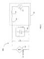
- FIG. 1is a schematic diagram illustrating one embodiment of a power source connected to an electric AC grid via an interface consistent with the present invention
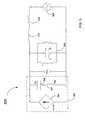
- FIG. 2is a schematic diagram illustrating an equivalent circuit of a current source connected to a load and to an electric grid consistent with the present invention
- FIG. 3is a schematic diagram illustrating another equivalent circuit of a current source connected to a load and to an electric grid consistent with the present invention.
- FIG. 4is a flow chart illustrating a method for preventing islanding of the grid-connected controlled current source consistent with the present invention.
- FIG. 1depicts one embodiment of a grid-connected power system 100 , which includes an energy source unit 102 and a power interface unit 104 which are connected to a utility grid 106 .
- a feedback control unit 120is connected to the grid 106 and the power interface unit 104 , which is configured to provide power to the grid 106 .
- a load 108which may or may not be present, is connected to the interface unit 104 and the utility grid 106 at node 110 . Alternately, the load 108 may be a plurality of loads.
- a switch 114may be positioned between the interface unit 104 and the utility grid 106 and load 108 (if present). Alternately, other protection devices may also be present therebetween.
- the source unit 102may be any kind of power or energy generating system, such as for example a solar panel, solar cell, fuel cell, wind generator, rotary generator, etc.
- a control integral to the power interface 104can draw maximum available power whenever power is available and useful. The control acts to maintain operation at an optimum power point, selected for the specific energy source technology.
- the interface unit 104may be a switching power converter, a power inverter and the like, and may include an energy storage unit (not shown).
- the switch 114may be a solid-state switching device, an electromechanical switching device, and the like.
- the feedback control unit 120configured to control an output current or current waveform of the power interface unit 104 , receives input corresponding to a voltage or voltage waveform sensed at the output terminals of the power interface unit 104 . Once received, the control unit 120 utilizes the sensed voltage input to control an output current of the power interface unit 104 . Alternately, the control unit 120 may be integral to the power interface unit 104 .
- An island eventoccurs when the load 108 remains energized when the utility grid 106 becomes de-energized.
- the occurrence of an islandrepresents an undesirable operation of the system.
- the power interface unit 104needs to be configured to sense the occurrence of an island condition, as required by regulatory requirements, and to cease injecting power into the grid 106 and load (if present).
- Switch device 114if present, may be opened as a further step.
- This controlled current methodis effectively a passive approach—power interface action is governed by a direct measurement at the voltage terminals.
- the control unit 120senses the voltage that is imposed by the grid on the output terminals and drives the output current of the power interface unit 104 wherein the output current is made to follow a reference or command current generated by the control unit 104 .
- an undesirable change in the sensed output voltage of the power interface unit 104is interpreted as an islanded condition which causes the control unit 120 to discontinue the current output from the power interface unit 104 .
- the reference currentneeds to be related to the actual electric grid voltage. For example, if the grid operates with a sinusoidal voltage at 60 Hz, the reference current should also be a sinusoid at 60 Hz. There is still debate on whether power converters should follow the grid voltage if it contains modest levels of distortion, but by regulatory standard, voltage distortion needs to be low.
- This controlled current methodis based entirely on terminal voltage sensing to detect whether or not the power interface unit 104 is connected to the power grid 106 . If the grid connection is lost, this condition is detected and the power interface unit 104 shuts down to meet requirements of anti-islanding protection.
- a key attributeis that the power interface unit 104 is configured to control its output current. This output current is controlled via the power electronics switching action to track a time-varying reference current. This output current, which under normal operating conditions is approximately sinusoidal, is fed into the connected electric power grid 106 .
- the output voltage of the power interface unit 104is imposed by the electric grid 106 , and will be a sinusoidal voltage with low or minimal distortion. As such, the output current delivered by the power interface unit 104 is also sinusoidal. If the grid connection is lost, the control unit 120 interacts with the power interface unit 104 in such a manner as to alter the power interface output voltage away from its sinusoidal operating condition. The resulting changes in the sensed voltage are detected and based on regulatory standards the power interface unit 104 shuts off by setting its output current to zero. The method automatically resets a period of time after the grid 106 is reconnected, once a sinusoidal voltage, imposed by the reconnected grid 106 , is sensed at the output terminals of the power interface unit 104 .
- the electric grid 106operating normally at 50 Hz or 60 Hz (the mains frequency), provides a sinusoidal voltage with low distortion.
- the methodis not limited to these applications, and can be used for other frequencies or even pre-determined non-sinusoidal grid waveforms.
- the reference current magnitude and phaseare set under normal conditions such that the mains frequency part of the current delivers a desired power and reactive power flow from the power interface unit 104 into the grid 106 . Adjustment of the magnitude and phase to accomplish control of power and reactive power is well known and is separate from this invention.
- FIG. 2an embodiment of an equivalent circuit 200 comprising a combination of the energy source 102 and interface unit 104 of FIG. 1 , hereafter referred to as a current-controlled interface unit 202 , connected to an electric grid 206 is shown.
- the electric grid 206is represented by a voltage source Vgrid 214 , a grid resistance Rgrid 216 and a grid inductance Lgrid 218 .
- the interface unit 202delivers a controlled output current I(t) to the grid 206 , where the voltage output Vout (t) of the power interface unit 202 is sensed or measured.
- G(s)represents the desired functional relationship between the voltage and current. It is well known to one skilled in the art that the actual output current of the power interface unit is subtly different than the desired reference current in Equation 1 due to the transfer function representing the power electronics process internal to the power interface unit 104 in FIG. 1 .
- FIG. 2The operation of FIG. 2 can be described as follows. Initially, the grid connection is present, but the interface output current is zero.
- the load 208shown as the parallel R-L-C test circuit specified by UL 1741, is supplied power from the grid 206 .
- the control process of the control unit 120shown in FIG. 1 , is initiated, since the detected grid voltage is nonzero, and the output current of the power interface units begins to track the reference current which takes the value G(s) V out (s). Any power difference or mismatch between the power interface output power and the load power demand, the power mismatch, is either absorbed or supplied by the grid 206 .
- the gain on G(s)is such that the power interface output current I(s) closely matches a current supplied to the load 208 and the grid current I grid is essentially zero.
- I load ( s )V ( s )/ Z ( s )
- I grid ( s )[ V g ( s ) ⁇ V ( S )] /Z grid ( s )
- I ( s )I load ( s ) ⁇ I grid ( s ). Equation 4
- FIG. 3an embodiment illustrating an equivalent circuit 300 of the circuit 200 of FIG. 2 is shown.
- This equivalent circuit 300includes a sensing network comprised of a capacitor C s 305 and a resistor R s 307 connected in series to form an RC filter used to create the output reference current.
- the position of the sense capacitor C s 305 relative to the resistor 307is selected to provide a high-pass characteristic.
- the controlled output current I(t)is selected to be proportional to the sense resistor voltage V r (t), with the proportional gain k determined so as to provide the desired output current magnitude.
- the gain kmay be adjusted by a maximum power point tracking process.
- FIG. 4a flow chart 400 illustrating a method for preventing islanding of the grid-connected controlled current source unit 202 of FIG. 2 is shown.
- This methodbegins at step 402 where the system establishes a predetermined current.
- the methodthen proceeds to step 404 , where the output current of the power interface is made to track the predetermined current.
- an output voltageis sensed.
- the methodthen proceeds to step 408 to determine whether the sensed output voltage is outside a predetermined voltage or waveform range. In the affirmative, the power delivered from the interface unit 202 is interrupted or disconnected from the grid 206 . Otherwise, the method returns to step 406 .
- the power deliverycan be resumed shortly, after a few line cycles or seconds of operation as determined by appropriate regulatory requirements, after the grid is reconnected and a sinusoidal voltage is re-imposed at the terminals of the interface unit 202 .
- the provided methodrelies on either stable or unstable voltage behavior when the grid connection is lost.
- the current referenceis derived directly from the output voltage of the interface unit 202 , and the following are all possible scenarios:
- the output currentis a signal i(t) that is proportional to the measured output of the power interface unit 202 .
- the output currentis a signal that is proportional to the output of a simple filter circuit (such as an RC or CR voltage divider) connected to the output voltage of the power interface 202 .
- a simple filter circuitsuch as an RC or CR voltage divider
- the output currentis proportional to the output of a differential equation in which the output voltage of the power interface unit 202 serves as the input.
- the differential equationis selected as any equation which will be sinusoidal at fixed frequency if and only if the output voltage is an externally imposed sinusoid.
- the output currentis proportional to a function of the measured output voltage of the power interface unit 202 that includes a term proportional to the time derivative of output voltage.
- any of these scenariosmay also have an intentional added time delay to provide the correct causality properties to enforce the non-invertible condition in Equation 5.
- the selected proportion or gainis chosen such that the actual current will result in delivery of the desired output power.
- a phase lag or leadcan be added to provide control over reactive power as well.
- the principle of choosing the specific form of the referenceis that a loss of connection to the grid 206 means that over time, the output voltage will change from its initial grid-based value. The simplest form of change is to the voltage magnitude, but the frequency will also change.
- a sensing circuitdetermines whether or not the output voltage is within pre-determined limits (for example, within ⁇ 20% of the nominal value or as specified in the relevant performance standards). If the voltage is outside these limits for more than about three to four line cycles, or the time specified by the relevant performance standards, the circuit will shut off by setting the reference current to zero. It is also possible to monitor the output frequency and shut off the power interface unit 202 if the measured frequency deviates from the performance standards. Both voltage and frequency sensing methods can be combined to make the arrangement robust.
- the advantages of the inventionare that no synchronization to the mains is required, nor in most implementations is a precise clock needed.
- the current magnitude and phasecan be set to deliver the desired real and reactive powers without significant effect on the grid connection detection process.
- the arrangementis passive and self-contained, and therefore well-suited to modular converters.
- the provide methodrelies on a simple derivation from the power converter terminal voltage and can detect loss of grid connection without additional external information.
- the function G(s) in FIG. 2is not arbitrary: it must be selected to ensure that the combined system with grid disconnected will yield either stable or unstable action (i.e. not marginally stable, which could result in a sustained resonance that may be undetectable).
- the “stability” or “instability”must be rapid enough to ensure unambiguous detection in well under two seconds. This is, however, straightforward. A high-pass filter with an added time delay of a few microseconds appears to be extremely robust in this context.
- the low connection impedanceassures that the output voltage of the interface unit 202 is nearly identical to the grid voltage.
- the approachworks without a synchronization process, and is a good match to modular power interface units, such as inverters.
- the primary requirementis that G(s) must not match the inverse of the effective load impedance—a condition that can be assured by choosing G(s) to include a time delay, to provide slow time variation of G(s), or other ensuring that the functional relation is not invertible.
Landscapes
- Engineering & Computer Science (AREA)
- Power Engineering (AREA)
- Inverter Devices (AREA)
Abstract
Description
I(s)=G(s)Vout(s) Equation 1
where the controlled output current I(s) is a Laplace transform of the controlled output current and represented with Laplace transforms of the product of G(s) and Vout(s), where Vout(s) is the Laplace transform of the sensed output voltage Vout(s) and G(s) is a Laplace transformed function that represents a differential equation or other mathematical relationship. Here G(s) represents the desired functional relationship between the voltage and current. It is well known to one skilled in the art that the actual output current of the power interface unit is subtly different than the desired reference current in Equation 1 due to the transfer function representing the power electronics process internal to the
Iload(s)=V(s)/Z(s), Equation 2
Igrid(s)=[Vg(s)−V(S)]/Zgrid(s), Equation 3
I(s)=Iload(s)−Igrid(s). Equation 4
G(s)≠Z−1(s) Equation 5
To see this, consider a form of G(s) that includes a time delay. The only way for G(s) to match Z−1(s) in this situation is for Z(s) to involve a time advance. This is not causal behavior, and would not be plausible for a realistic system. Thus, it is not difficult to prevent the condition G(s)Z(s)=1 from occurring, either by enforcing a time delay within G(s) or by imposing a small time variation on G(s) such that the condition is not met over any substantial time interval. In either case, loss of the grid can be detected quickly. These techniques can minimize any non-detection zone and mean that loss of the grid is detected provided only that the loss of grid has sufficiently high impedance. Tests of the method have shown that “sufficiently high” means more than a few ohms, a level that covers almost any plausible loss of connection scenario.
- 1. The function is chosen to make the operation stable at the instantaneous current value i(t)=0. In this case, when the external grid connection is removed, the method can actively drive the controlled current i(t) to zero over time as the only possible stable condition. This effectively discontinues power flow.
- 2. The function is chosen to make the operation unstable when the external source is not connected. In this case, when the grid connection is lost, the voltage will immediately start to grow or change rapidly—conditions that are easily detected by conventional methods which can take action to turn off the power converter.
Iref(s)=kG(s)V(s) Equation 6
where k controls the desired power flow. In summary, the current-controlled
Claims (20)
Priority Applications (1)
| Application Number | Priority Date | Filing Date | Title |
|---|---|---|---|
| US13/050,592US8423312B2 (en) | 2007-09-04 | 2011-03-17 | Voltage-sensed system and method for anti-islanding protection of grid-connected inverters |
Applications Claiming Priority (2)
| Application Number | Priority Date | Filing Date | Title |
|---|---|---|---|
| US11/849,827US7945413B2 (en) | 2007-09-04 | 2007-09-04 | Voltage-sensed system and method for anti-islanding protection of grid-connected inverters |
| US13/050,592US8423312B2 (en) | 2007-09-04 | 2011-03-17 | Voltage-sensed system and method for anti-islanding protection of grid-connected inverters |
Related Parent Applications (1)
| Application Number | Title | Priority Date | Filing Date |
|---|---|---|---|
| US11/849,827ContinuationUS7945413B2 (en) | 2007-09-04 | 2007-09-04 | Voltage-sensed system and method for anti-islanding protection of grid-connected inverters |
Publications (2)
| Publication Number | Publication Date |
|---|---|
| US20110164440A1 US20110164440A1 (en) | 2011-07-07 |
| US8423312B2true US8423312B2 (en) | 2013-04-16 |
Family
ID=40407195
Family Applications (2)
| Application Number | Title | Priority Date | Filing Date |
|---|---|---|---|
| US11/849,827Active2028-10-19US7945413B2 (en) | 2007-09-04 | 2007-09-04 | Voltage-sensed system and method for anti-islanding protection of grid-connected inverters |
| US13/050,592ActiveUS8423312B2 (en) | 2007-09-04 | 2011-03-17 | Voltage-sensed system and method for anti-islanding protection of grid-connected inverters |
Family Applications Before (1)
| Application Number | Title | Priority Date | Filing Date |
|---|---|---|---|
| US11/849,827Active2028-10-19US7945413B2 (en) | 2007-09-04 | 2007-09-04 | Voltage-sensed system and method for anti-islanding protection of grid-connected inverters |
Country Status (2)
| Country | Link |
|---|---|
| US (2) | US7945413B2 (en) |
| WO (1) | WO2009032876A1 (en) |
Cited By (13)
| Publication number | Priority date | Publication date | Assignee | Title |
|---|---|---|---|---|
| US9997920B2 (en) | 2014-06-11 | 2018-06-12 | Sinewatts, Inc. | System and method for islanding detection and prevention in distributed generation |
| USD822890S1 (en) | 2016-09-07 | 2018-07-10 | Felxtronics Ap, Llc | Lighting apparatus |
| USD832495S1 (en) | 2017-08-18 | 2018-10-30 | Flex Ltd. | Lighting module locking mechanism |
| USD832494S1 (en) | 2017-08-09 | 2018-10-30 | Flex Ltd. | Lighting module heatsink |
| USD833061S1 (en) | 2017-08-09 | 2018-11-06 | Flex Ltd. | Lighting module locking endcap |
| USD846793S1 (en) | 2017-08-09 | 2019-04-23 | Flex Ltd. | Lighting module locking mechanism |
| USD862778S1 (en) | 2017-08-22 | 2019-10-08 | Flex Ltd | Lighting module lens |
| USD862777S1 (en) | 2017-08-09 | 2019-10-08 | Flex Ltd. | Lighting module wide distribution lens |
| USD872319S1 (en) | 2017-08-09 | 2020-01-07 | Flex Ltd. | Lighting module LED light board |
| USD877964S1 (en) | 2017-08-09 | 2020-03-10 | Flex Ltd. | Lighting module |
| USD888323S1 (en) | 2017-09-07 | 2020-06-23 | Flex Ltd | Lighting module wire guard |
| US10775030B2 (en) | 2017-05-05 | 2020-09-15 | Flex Ltd. | Light fixture device including rotatable light modules |
| US11791633B2 (en) | 2011-07-11 | 2023-10-17 | Generac Power Systems, Inc. | Systems and methods for increasing output current quality, output power, and reliability of grid-interactive inverters |
Families Citing this family (75)
| Publication number | Priority date | Publication date | Assignee | Title |
|---|---|---|---|---|
| US10693415B2 (en) | 2007-12-05 | 2020-06-23 | Solaredge Technologies Ltd. | Testing of a photovoltaic panel |
| US11881814B2 (en) | 2005-12-05 | 2024-01-23 | Solaredge Technologies Ltd. | Testing of a photovoltaic panel |
| US11309832B2 (en) | 2006-12-06 | 2022-04-19 | Solaredge Technologies Ltd. | Distributed power harvesting systems using DC power sources |
| US9112379B2 (en) | 2006-12-06 | 2015-08-18 | Solaredge Technologies Ltd. | Pairing of components in a direct current distributed power generation system |
| US9088178B2 (en) | 2006-12-06 | 2015-07-21 | Solaredge Technologies Ltd | Distributed power harvesting systems using DC power sources |
| US11888387B2 (en) | 2006-12-06 | 2024-01-30 | Solaredge Technologies Ltd. | Safety mechanisms, wake up and shutdown methods in distributed power installations |
| US11296650B2 (en) | 2006-12-06 | 2022-04-05 | Solaredge Technologies Ltd. | System and method for protection during inverter shutdown in distributed power installations |
| US8963369B2 (en) | 2007-12-04 | 2015-02-24 | Solaredge Technologies Ltd. | Distributed power harvesting systems using DC power sources |
| US8319483B2 (en) | 2007-08-06 | 2012-11-27 | Solaredge Technologies Ltd. | Digital average input current control in power converter |
| US11569659B2 (en) | 2006-12-06 | 2023-01-31 | Solaredge Technologies Ltd. | Distributed power harvesting systems using DC power sources |
| US9130401B2 (en) | 2006-12-06 | 2015-09-08 | Solaredge Technologies Ltd. | Distributed power harvesting systems using DC power sources |
| US12316274B2 (en) | 2006-12-06 | 2025-05-27 | Solaredge Technologies Ltd. | Pairing of components in a direct current distributed power generation system |
| US8473250B2 (en) | 2006-12-06 | 2013-06-25 | Solaredge, Ltd. | Monitoring of distributed power harvesting systems using DC power sources |
| US11687112B2 (en) | 2006-12-06 | 2023-06-27 | Solaredge Technologies Ltd. | Distributed power harvesting systems using DC power sources |
| US8013472B2 (en) | 2006-12-06 | 2011-09-06 | Solaredge, Ltd. | Method for distributed power harvesting using DC power sources |
| US11855231B2 (en) | 2006-12-06 | 2023-12-26 | Solaredge Technologies Ltd. | Distributed power harvesting systems using DC power sources |
| US8816535B2 (en)* | 2007-10-10 | 2014-08-26 | Solaredge Technologies, Ltd. | System and method for protection during inverter shutdown in distributed power installations |
| US11735910B2 (en) | 2006-12-06 | 2023-08-22 | Solaredge Technologies Ltd. | Distributed power system using direct current power sources |
| US8947194B2 (en) | 2009-05-26 | 2015-02-03 | Solaredge Technologies Ltd. | Theft detection and prevention in a power generation system |
| US8618692B2 (en) | 2007-12-04 | 2013-12-31 | Solaredge Technologies Ltd. | Distributed power system using direct current power sources |
| US8319471B2 (en) | 2006-12-06 | 2012-11-27 | Solaredge, Ltd. | Battery power delivery module |
| US8384243B2 (en) | 2007-12-04 | 2013-02-26 | Solaredge Technologies Ltd. | Distributed power harvesting systems using DC power sources |
| WO2009072076A2 (en) | 2007-12-05 | 2009-06-11 | Solaredge Technologies Ltd. | Current sensing on a mosfet |
| WO2009073867A1 (en) | 2007-12-05 | 2009-06-11 | Solaredge, Ltd. | Parallel connected inverters |
| US11264947B2 (en) | 2007-12-05 | 2022-03-01 | Solaredge Technologies Ltd. | Testing of a photovoltaic panel |
| CN105244905B (en) | 2007-12-05 | 2019-05-21 | 太阳能安吉有限公司 | Release mechanism in distributed power device is waken up and method for closing |
| US8111052B2 (en) | 2008-03-24 | 2012-02-07 | Solaredge Technologies Ltd. | Zero voltage switching |
| EP2294669B8 (en) | 2008-05-05 | 2016-12-07 | Solaredge Technologies Ltd. | Direct current power combiner |
| KR100993108B1 (en)* | 2008-05-30 | 2010-11-08 | 군산대학교산학협력단 | Grid-connected photovoltaic power generation system with improved power quality and power saving |
| US8068352B2 (en)* | 2008-12-19 | 2011-11-29 | Caterpillar Inc. | Power inverter control for grid-tie transition |
| EP2254224A1 (en)* | 2009-05-18 | 2010-11-24 | SMA Solar Technology AG | Method for discharging a filter capacitor at the output of an inverter device and inverter device |
| US12418177B2 (en) | 2009-10-24 | 2025-09-16 | Solaredge Technologies Ltd. | Distributed power system using direct current power sources |
| US8334618B2 (en) | 2009-11-13 | 2012-12-18 | Eaton Corporation | Method and area electric power system detecting islanding by employing controlled reactive power injection by a number of inverters |
| US8710699B2 (en) | 2009-12-01 | 2014-04-29 | Solaredge Technologies Ltd. | Dual use photovoltaic system |
| US8766696B2 (en) | 2010-01-27 | 2014-07-01 | Solaredge Technologies Ltd. | Fast voltage level shifter circuit |
| CN101917016B (en)* | 2010-07-21 | 2012-10-31 | 北京交通大学 | Energy storage cascaded multi-level photovoltaic grid-connected power generation control system |
| WO2012031992A2 (en)* | 2010-09-06 | 2012-03-15 | Sma Solar Technology Ag | Method for stabilizing an electric grid |
| US10673222B2 (en) | 2010-11-09 | 2020-06-02 | Solaredge Technologies Ltd. | Arc detection and prevention in a power generation system |
| US10673229B2 (en) | 2010-11-09 | 2020-06-02 | Solaredge Technologies Ltd. | Arc detection and prevention in a power generation system |
| US10230310B2 (en) | 2016-04-05 | 2019-03-12 | Solaredge Technologies Ltd | Safety switch for photovoltaic systems |
| GB2485527B (en) | 2010-11-09 | 2012-12-19 | Solaredge Technologies Ltd | Arc detection and prevention in a power generation system |
| GB2486408A (en) | 2010-12-09 | 2012-06-20 | Solaredge Technologies Ltd | Disconnection of a string carrying direct current |
| GB2483317B (en) | 2011-01-12 | 2012-08-22 | Solaredge Technologies Ltd | Serially connected inverters |
| CN102136736B (en)* | 2011-02-24 | 2013-04-17 | 复旦大学 | Method and device for inhibiting and eliminating leakage current of photovoltaic grid connection system without transformer |
| US8310105B2 (en)* | 2011-08-30 | 2012-11-13 | Renewable Power Conversion, Inc. | Centralized islanding protection for distributed renewable energy generators |
| US8570005B2 (en) | 2011-09-12 | 2013-10-29 | Solaredge Technologies Ltd. | Direct current link circuit |
| US8907525B2 (en) | 2011-12-14 | 2014-12-09 | General Electric Company | Method and system for islanding detection and protection |
| GB2498365A (en) | 2012-01-11 | 2013-07-17 | Solaredge Technologies Ltd | Photovoltaic module |
| GB2498790A (en) | 2012-01-30 | 2013-07-31 | Solaredge Technologies Ltd | Maximising power in a photovoltaic distributed power system |
| GB2498791A (en) | 2012-01-30 | 2013-07-31 | Solaredge Technologies Ltd | Photovoltaic panel circuitry |
| US9853565B2 (en) | 2012-01-30 | 2017-12-26 | Solaredge Technologies Ltd. | Maximized power in a photovoltaic distributed power system |
| GB2499991A (en) | 2012-03-05 | 2013-09-11 | Solaredge Technologies Ltd | DC link circuit for photovoltaic array |
| US9312682B2 (en) | 2012-05-14 | 2016-04-12 | General Electric Company | System and method for overvoltage protection |
| EP3499695B1 (en) | 2012-05-25 | 2024-09-18 | Solaredge Technologies Ltd. | Circuit for interconnected direct current power sources |
| US10115841B2 (en) | 2012-06-04 | 2018-10-30 | Solaredge Technologies Ltd. | Integrated photovoltaic panel circuitry |
| CN102868174B (en)* | 2012-08-31 | 2014-11-26 | 天津理工大学 | Photovoltaic grid-connected system for restraining chaos based on DSP (Digital Signal Processor) as well as working method thereof |
| US9513352B2 (en) | 2012-09-28 | 2016-12-06 | General Electric Company | System and method for inductively communicating data |
| US9620994B2 (en) | 2013-01-17 | 2017-04-11 | Eaton Corporation | Method and system of anti-islanding of a microgrid in a grid-connected microgrid system |
| US9065323B2 (en) | 2013-03-04 | 2015-06-23 | Astec International Limited | Systems and methods for detecting islanding conditions in grid-tied inverters |
| US9548619B2 (en) | 2013-03-14 | 2017-01-17 | Solaredge Technologies Ltd. | Method and apparatus for storing and depleting energy |
| US9941813B2 (en) | 2013-03-14 | 2018-04-10 | Solaredge Technologies Ltd. | High frequency multi-level inverter |
| EP3506370B1 (en) | 2013-03-15 | 2023-12-20 | Solaredge Technologies Ltd. | Bypass mechanism |
| CN104868764B (en)* | 2014-02-26 | 2017-08-04 | 全汉企业股份有限公司 | Inverter and power supply conversion method thereof |
| US9318974B2 (en) | 2014-03-26 | 2016-04-19 | Solaredge Technologies Ltd. | Multi-level inverter with flying capacitor topology |
| US10069304B2 (en)* | 2014-06-11 | 2018-09-04 | Sinewatts, Inc. | System and method for islanding detection and prevention in distributed generation |
| US9627961B1 (en)* | 2015-12-11 | 2017-04-18 | National Chung Shan Institute Of Science And Technology | Mixed power supply device with a merging network switch |
| US11081608B2 (en) | 2016-03-03 | 2021-08-03 | Solaredge Technologies Ltd. | Apparatus and method for determining an order of power devices in power generation systems |
| US10599113B2 (en) | 2016-03-03 | 2020-03-24 | Solaredge Technologies Ltd. | Apparatus and method for determining an order of power devices in power generation systems |
| CN107153212B (en) | 2016-03-03 | 2023-07-28 | 太阳能安吉科技有限公司 | Method for mapping a power generation facility |
| US11177663B2 (en) | 2016-04-05 | 2021-11-16 | Solaredge Technologies Ltd. | Chain of power devices |
| US12057807B2 (en) | 2016-04-05 | 2024-08-06 | Solaredge Technologies Ltd. | Chain of power devices |
| US11018623B2 (en) | 2016-04-05 | 2021-05-25 | Solaredge Technologies Ltd. | Safety switch for photovoltaic systems |
| JP6706384B2 (en)* | 2017-03-29 | 2020-06-03 | 東芝三菱電機産業システム株式会社 | Power converter and test method thereof |
| EP3631932B1 (en)* | 2017-05-31 | 2023-07-26 | Schneider Electric Solar Inverters USA, Inc. | Systems and methods for islanding detection |
| CN114846714B (en)* | 2019-12-27 | 2025-09-23 | Abb瑞士股份有限公司 | Method and device for detecting power grid isolation |
Citations (19)
| Publication number | Priority date | Publication date | Assignee | Title |
|---|---|---|---|---|
| US4724363A (en)* | 1986-06-24 | 1988-02-09 | General Electric Company | Current control circuit for high voltage applications |
| US5446645A (en)* | 1992-02-18 | 1995-08-29 | Hitachi, Ltd. | Inverter apparatus and uinterruptible power supply using the same |
| US5452173A (en)* | 1992-09-08 | 1995-09-19 | Challenge Technologies, Inc. | Diagnostic circuit protection device |
| US5602462A (en)* | 1995-02-21 | 1997-02-11 | Best Power Technology, Incorporated | Uninterruptible power system |
| US5668713A (en)* | 1995-10-16 | 1997-09-16 | Sharp Kabushiki Kaisha | Inverter control method and inverter control device performing feedback control by suppressing delay |
| US5719758A (en)* | 1995-12-20 | 1998-02-17 | Sharp Kabushiki Kaisha | Inverter control method and inverter apparatus using the method |
| US6172998B1 (en) | 1996-11-18 | 2001-01-09 | Mitsubishi Chemical Corporation | Semiconductor laser diode |
| US6429546B1 (en)* | 1998-11-20 | 2002-08-06 | Georgia Tech Research Corporation | Systems and methods for preventing islanding of grid-connected electrical power systems |
| US6489755B1 (en) | 2000-09-18 | 2002-12-03 | Adtran, Inc. | Active ripple and noise filter for telecommunication equipment powering |
| US20030080741A1 (en) | 2001-10-26 | 2003-05-01 | Lerow Kevin E. | Anti-islanding techniques for distributed power generation |
| US6801442B2 (en) | 2001-10-01 | 2004-10-05 | Canon Kabushiki Kaisha | Power conversion apparatus, power conversion system, and islanding operation detection method |
| US6810339B2 (en)* | 1997-11-24 | 2004-10-26 | Plug Power, Inc. | Anti-islanding method and apparatus for distributed power generation |
| US6853940B2 (en)* | 2002-01-16 | 2005-02-08 | Ballard Power Systems Corporation | Anti-islanding device and method for grid connected inverters using random noise injection |
| US7015597B2 (en)* | 2003-09-11 | 2006-03-21 | Square D Company | Power regulator for power inverter |
| US7289341B2 (en) | 2004-12-14 | 2007-10-30 | Advanced Energy Industries, Inc. | Power supply adaptive feedforward control circuit |
| US7339287B2 (en) | 2002-06-23 | 2008-03-04 | Powerlynx A/S | Power converter |
| US7408268B1 (en)* | 2005-08-04 | 2008-08-05 | Magnetek, S.P.A. | Anti-islanding method and system for distributed power generation systems |
| US20090296348A1 (en) | 2008-05-20 | 2009-12-03 | Miles Clayton Russell | Ac photovoltaic module and inverter assembly |
| US7899632B2 (en) | 2007-07-16 | 2011-03-01 | Enphase Energy, Inc. | Method and apparatus for anti-islanding of distributed power generation systems |
- 2007
- 2007-09-04USUS11/849,827patent/US7945413B2/enactiveActive
- 2008
- 2008-09-04WOPCT/US2008/075178patent/WO2009032876A1/enactiveApplication Filing
- 2011
- 2011-03-17USUS13/050,592patent/US8423312B2/enactiveActive
Patent Citations (20)
| Publication number | Priority date | Publication date | Assignee | Title |
|---|---|---|---|---|
| US4724363A (en)* | 1986-06-24 | 1988-02-09 | General Electric Company | Current control circuit for high voltage applications |
| US5446645A (en)* | 1992-02-18 | 1995-08-29 | Hitachi, Ltd. | Inverter apparatus and uinterruptible power supply using the same |
| US5452173A (en)* | 1992-09-08 | 1995-09-19 | Challenge Technologies, Inc. | Diagnostic circuit protection device |
| US5602462A (en)* | 1995-02-21 | 1997-02-11 | Best Power Technology, Incorporated | Uninterruptible power system |
| US5668713A (en)* | 1995-10-16 | 1997-09-16 | Sharp Kabushiki Kaisha | Inverter control method and inverter control device performing feedback control by suppressing delay |
| US5719758A (en)* | 1995-12-20 | 1998-02-17 | Sharp Kabushiki Kaisha | Inverter control method and inverter apparatus using the method |
| US6172998B1 (en) | 1996-11-18 | 2001-01-09 | Mitsubishi Chemical Corporation | Semiconductor laser diode |
| US6810339B2 (en)* | 1997-11-24 | 2004-10-26 | Plug Power, Inc. | Anti-islanding method and apparatus for distributed power generation |
| US6429546B1 (en)* | 1998-11-20 | 2002-08-06 | Georgia Tech Research Corporation | Systems and methods for preventing islanding of grid-connected electrical power systems |
| US6489755B1 (en) | 2000-09-18 | 2002-12-03 | Adtran, Inc. | Active ripple and noise filter for telecommunication equipment powering |
| US6801442B2 (en) | 2001-10-01 | 2004-10-05 | Canon Kabushiki Kaisha | Power conversion apparatus, power conversion system, and islanding operation detection method |
| US20030080741A1 (en) | 2001-10-26 | 2003-05-01 | Lerow Kevin E. | Anti-islanding techniques for distributed power generation |
| US7138728B2 (en) | 2001-10-26 | 2006-11-21 | Youtility, Inc. | Anti-islanding techniques for distributed power generation |
| US6853940B2 (en)* | 2002-01-16 | 2005-02-08 | Ballard Power Systems Corporation | Anti-islanding device and method for grid connected inverters using random noise injection |
| US7339287B2 (en) | 2002-06-23 | 2008-03-04 | Powerlynx A/S | Power converter |
| US7015597B2 (en)* | 2003-09-11 | 2006-03-21 | Square D Company | Power regulator for power inverter |
| US7289341B2 (en) | 2004-12-14 | 2007-10-30 | Advanced Energy Industries, Inc. | Power supply adaptive feedforward control circuit |
| US7408268B1 (en)* | 2005-08-04 | 2008-08-05 | Magnetek, S.P.A. | Anti-islanding method and system for distributed power generation systems |
| US7899632B2 (en) | 2007-07-16 | 2011-03-01 | Enphase Energy, Inc. | Method and apparatus for anti-islanding of distributed power generation systems |
| US20090296348A1 (en) | 2008-05-20 | 2009-12-03 | Miles Clayton Russell | Ac photovoltaic module and inverter assembly |
Non-Patent Citations (7)
| Title |
|---|
| Beom, et al., "An Improved Method for Anti-Islanding by Reactive Power Control," in Proceedings, IEEE Eighth International Conference of Electrical Machines and Systems, Nanjing, China, 2005, vol. 2, pp. 965-970-(Best Copy Available). |
| Bower et al., "Evaluation of Islanding Detection Methods for Utility-Interactive Inverters in Photovoltaic Systems," Photovoltaic Systems Research and Development, Sandia National Laboratories, Albuquerque, NM, Technical Report No. SAND2002-3591, Nov. 2002. |
| International Preliminary Report for International Patent Application No. PCT/US2008/075178, Mar. 18, 2010, 6 pgs. |
| International Search Report for International Patent Application No. PCT/US2008/075178, Nov. 6, 2008, 8 pgs. |
| Kobayashi, et al., "Method for Preventing Islanding Phenomenon on a Utility Grid with a Number of Small Scale PV Systems," in Record, IEEE Photovoltaic Specialists Conference, Las Vegas, NV, 1991, vol. 1, pp. 695-700. |
| Kobayashi, et al., "Statistical Evaluation of Optimum Islanding Preventing Method for Utility Interactive Small Scale Dispersed PV Systems," in Record, IEEE Photovoltaic Specialists Conference, Waikoloa, HI, 1994, vol. 1, pp. 1085-1088. |
| Noor, et al., "Unintentional Islanding and Comparison of Prevention Techniques," Proceedings, IEEE North American Power Symposium, Ames, IA, 2005, pp. 90-96. |
Cited By (21)
| Publication number | Priority date | Publication date | Assignee | Title |
|---|---|---|---|---|
| US11791633B2 (en) | 2011-07-11 | 2023-10-17 | Generac Power Systems, Inc. | Systems and methods for increasing output current quality, output power, and reliability of grid-interactive inverters |
| US12176719B2 (en) | 2011-07-11 | 2024-12-24 | Generac Power Systems, Inc. | Systems and methods for increasing output current quality, output power, and reliability of grid-interactive inverters |
| US9997920B2 (en) | 2014-06-11 | 2018-06-12 | Sinewatts, Inc. | System and method for islanding detection and prevention in distributed generation |
| USD822890S1 (en) | 2016-09-07 | 2018-07-10 | Felxtronics Ap, Llc | Lighting apparatus |
| US10775030B2 (en) | 2017-05-05 | 2020-09-15 | Flex Ltd. | Light fixture device including rotatable light modules |
| USD853627S1 (en) | 2017-08-09 | 2019-07-09 | Flex Ltd | Lighting module locking endcap |
| USD833061S1 (en) | 2017-08-09 | 2018-11-06 | Flex Ltd. | Lighting module locking endcap |
| USD853625S1 (en) | 2017-08-09 | 2019-07-09 | Flex Ltd | Lighting module heatsink |
| USD1010915S1 (en) | 2017-08-09 | 2024-01-09 | Linmore Labs Led, Inc. | Lighting module |
| USD905325S1 (en) | 2017-08-09 | 2020-12-15 | Flex Ltd | Lighting module |
| USD846793S1 (en) | 2017-08-09 | 2019-04-23 | Flex Ltd. | Lighting module locking mechanism |
| USD862777S1 (en) | 2017-08-09 | 2019-10-08 | Flex Ltd. | Lighting module wide distribution lens |
| USD872319S1 (en) | 2017-08-09 | 2020-01-07 | Flex Ltd. | Lighting module LED light board |
| USD877964S1 (en) | 2017-08-09 | 2020-03-10 | Flex Ltd. | Lighting module |
| USD885615S1 (en) | 2017-08-09 | 2020-05-26 | Flex Ltd. | Lighting module LED light board |
| USD853629S1 (en) | 2017-08-09 | 2019-07-09 | Flex Ltd | Lighting module locking mechanism |
| USD832494S1 (en) | 2017-08-09 | 2018-10-30 | Flex Ltd. | Lighting module heatsink |
| USD853628S1 (en) | 2017-08-18 | 2019-07-09 | Flex Ltd. | Lighting module locking mechanism |
| USD832495S1 (en) | 2017-08-18 | 2018-10-30 | Flex Ltd. | Lighting module locking mechanism |
| USD862778S1 (en) | 2017-08-22 | 2019-10-08 | Flex Ltd | Lighting module lens |
| USD888323S1 (en) | 2017-09-07 | 2020-06-23 | Flex Ltd | Lighting module wire guard |
Also Published As
| Publication number | Publication date |
|---|---|
| US7945413B2 (en) | 2011-05-17 |
| WO2009032876A1 (en) | 2009-03-12 |
| US20110164440A1 (en) | 2011-07-07 |
| US20090059631A1 (en) | 2009-03-05 |
Similar Documents
| Publication | Publication Date | Title |
|---|---|---|
| US8423312B2 (en) | Voltage-sensed system and method for anti-islanding protection of grid-connected inverters | |
| US10348217B2 (en) | Distributed voltage source inverters | |
| CN106058911B (en) | Detection method for islanding in grid-connected power generation systems and related DC/AC conversion devices | |
| US8957666B2 (en) | Anti-islanding protection in three-phase converters using grid synchronization small-signal stability | |
| Srinivas et al. | Seamless mode transition technique for virtual synchronous generators and method thereof | |
| KR101646170B1 (en) | Power System Control Method for Operation With Grid-Connection and Isolation | |
| Bhattacharya et al. | Efficient power sharing approach for photovoltaic generation based microgrids | |
| Meng et al. | A self-adaptive controller for inverter with seamless transfer and automatic pre-synchronization capability | |
| Ghzaiel et al. | Grid impedance estimation based hybrid islanding detection method for AC microgrids | |
| Meegahapola et al. | Synchronous islanded operation of an inverter interfaced renewable rich microgrid using synchrophasors | |
| CN119096442A (en) | Control design of photovoltaic systems in grid-connected operation for grid support | |
| Kumar et al. | Multimode features of CIPNLMS-MFX controlled single-phase PV system with finite state machine based islanding/synchronization under grid outage | |
| Kulkarni et al. | Operation of the microgrid with improved droop control strategy and an effective islanding detection technique for automatic mode switching | |
| KR20200088159A (en) | Grid-connected inverter and method for detecting islanding of grid-connected inverter | |
| Li et al. | New control schemes of output power decoupling based on synchronverter | |
| Gaonkar et al. | Seamless transfer of microturbine generation system operation between grid-connected and islanding modes | |
| Jayakumar et al. | Implementation of solar PV system unified ZSI-based dynamic voltage restorer with U-SOGI control scheme for power quality improvement | |
| Rocabert et al. | Microgrid connection management based on an intelligent connection agent | |
| Dietmannsberger et al. | Restoration of low-voltage distribution systems with inverter-interfaced DG units | |
| Buticchi et al. | Frequency-based control of a micro-grid with multiple renewable energy sources | |
| Meyers et al. | Time disciplined non-PLL active synchronization for grid forming inverters | |
| Liserre et al. | Universal operation of small/medium‐sized renewable energy systems | |
| Tao et al. | Control of grid-interactive inverters as used in small distributed generators | |
| Thacker | Control of power conversion systems for the intentional islanding of distributed generation units | |
| Azrik Roslan et al. | Semicentralized power sharing scheme for islanded parallel‐connected inverters |
Legal Events
| Date | Code | Title | Description |
|---|---|---|---|
| AS | Assignment | Owner name:SMARTSPARK ENERGY SYSTEMS, INC., ILLINOIS Free format text:ASSIGNMENT OF ASSIGNORS INTEREST;ASSIGNOR:KREIN, PHILIP T.;REEL/FRAME:026284/0283 Effective date:20070831 Owner name:SOLARBRIDGE TECHNOLOGIES, INC., TEXAS Free format text:CHANGE OF NAME;ASSIGNOR:SMARTSPARK ENERGY SYSTEMS, INC.;REEL/FRAME:026284/0789 Effective date:20090417 | |
| STCF | Information on status: patent grant | Free format text:PATENTED CASE | |
| AS | Assignment | Owner name:SILICON VALLEY BANK, CALIFORNIA Free format text:SECURITY INTEREST;ASSIGNOR:SOLARBRIDGE TECHNOLOGIES, INC.;REEL/FRAME:033677/0870 Effective date:20130724 | |
| FEPP | Fee payment procedure | Free format text:PAT HOLDER NO LONGER CLAIMS SMALL ENTITY STATUS, ENTITY STATUS SET TO UNDISCOUNTED (ORIGINAL EVENT CODE: STOL); ENTITY STATUS OF PATENT OWNER: LARGE ENTITY | |
| AS | Assignment | Owner name:SUNPOWER CORPORATION, CALIFORNIA Free format text:ASSIGNMENT OF ASSIGNORS INTEREST;ASSIGNOR:SOLARBRIDGE TECHNOLOGIES, INC.;REEL/FRAME:034687/0232 Effective date:20141218 Owner name:SOLARBRIDGE TECHNOLOGIES, INC., TEXAS Free format text:RELEASE BY SECURED PARTY;ASSIGNOR:SILICON VALLEY BANK;REEL/FRAME:034681/0475 Effective date:20141107 | |
| FPAY | Fee payment | Year of fee payment:4 | |
| AS | Assignment | Owner name:ENPHASE ENERGY, INC., CALIFORNIA Free format text:ASSIGNMENT OF ASSIGNORS INTEREST;ASSIGNOR:SUNPOWER CORPORATION;REEL/FRAME:046964/0203 Effective date:20180809 | |
| MAFP | Maintenance fee payment | Free format text:PAYMENT OF MAINTENANCE FEE, 8TH YEAR, LARGE ENTITY (ORIGINAL EVENT CODE: M1552); ENTITY STATUS OF PATENT OWNER: LARGE ENTITY Year of fee payment:8 | |
| MAFP | Maintenance fee payment | Free format text:PAYMENT OF MAINTENANCE FEE, 12TH YEAR, LARGE ENTITY (ORIGINAL EVENT CODE: M1553); ENTITY STATUS OF PATENT OWNER: LARGE ENTITY Year of fee payment:12 |