US8423139B2 - Methods, devices and systems for cardiac rhythm management using an electrode arrangement - Google Patents
Methods, devices and systems for cardiac rhythm management using an electrode arrangementDownload PDFInfo
- Publication number
- US8423139B2 US8423139B2US12/147,376US14737608AUS8423139B2US 8423139 B2US8423139 B2US 8423139B2US 14737608 AUS14737608 AUS 14737608AUS 8423139 B2US8423139 B2US 8423139B2
- Authority
- US
- United States
- Prior art keywords
- pacing
- heart
- electrodes
- electrode
- catheter
- Prior art date
- Legal status (The legal status is an assumption and is not a legal conclusion. Google has not performed a legal analysis and makes no representation as to the accuracy of the status listed.)
- Expired - Fee Related, expires
Links
- 238000000034methodMethods0.000titleclaimsabstractdescription82
- 230000000747cardiac effectEffects0.000titleabstractdescription34
- 230000033764rhythmic processEffects0.000titledescription5
- 210000002216heartAnatomy0.000claimsabstractdescription102
- 210000004375bundle of hisAnatomy0.000claimsabstractdescription39
- 210000005003heart tissueAnatomy0.000claimsabstractdescription39
- 210000004165myocardiumAnatomy0.000claimsabstractdescription24
- 210000005241right ventricleAnatomy0.000claimsdescription119
- 230000004217heart functionEffects0.000claimsdescription44
- 230000004913activationEffects0.000claimsdescription35
- 230000000694effectsEffects0.000claimsdescription27
- 230000001976improved effectEffects0.000claimsdescription23
- 238000012544monitoring processMethods0.000claimsdescription23
- 230000006870functionEffects0.000claimsdescription19
- 230000006872improvementEffects0.000claimsdescription11
- 230000004044responseEffects0.000claimsdescription11
- 238000005194fractionationMethods0.000claimsdescription9
- 239000000463materialSubstances0.000claimsdescription5
- 239000002086nanomaterialSubstances0.000claimsdescription4
- 230000005226mechanical processes and functionsEffects0.000claimsdescription3
- 229940121363anti-inflammatory agentDrugs0.000claimsdescription2
- 239000002260anti-inflammatory agentSubstances0.000claimsdescription2
- 239000011248coating agentSubstances0.000claimsdescription2
- 238000000576coating methodMethods0.000claimsdescription2
- 230000003110anti-inflammatory effectEffects0.000claims1
- 230000007246mechanismEffects0.000abstractdescription27
- 210000005240left ventricleAnatomy0.000description78
- 230000008602contractionEffects0.000description42
- 230000000638stimulationEffects0.000description41
- 230000002861ventricularEffects0.000description26
- 210000003748coronary sinusAnatomy0.000description22
- 210000005245right atriumAnatomy0.000description18
- 239000003990capacitorSubstances0.000description16
- 206010006580Bundle branch block leftDiseases0.000description15
- 206010006578Bundle-Branch BlockDiseases0.000description15
- 210000002837heart atriumAnatomy0.000description15
- 201000001715left bundle branch hemiblockDiseases0.000description15
- 206010019280Heart failuresDiseases0.000description13
- 230000001360synchronised effectEffects0.000description12
- 210000001519tissueAnatomy0.000description12
- 230000008901benefitEffects0.000description11
- 238000011282treatmentMethods0.000description11
- 238000013507mappingMethods0.000description10
- 206010007559Cardiac failure congestiveDiseases0.000description9
- 230000001746atrial effectEffects0.000description9
- 239000004020conductorSubstances0.000description9
- 230000009977dual effectEffects0.000description9
- 230000004936stimulating effectEffects0.000description9
- 230000005684electric fieldEffects0.000description8
- 238000005259measurementMethods0.000description8
- 238000002560therapeutic procedureMethods0.000description8
- 210000001186vagus nerveAnatomy0.000description8
- 210000001992atrioventricular nodeAnatomy0.000description7
- 238000013461designMethods0.000description7
- 208000001871TachycardiaDiseases0.000description6
- 238000004458analytical methodMethods0.000description6
- 238000013459approachMethods0.000description6
- 208000006218bradycardiaDiseases0.000description6
- 230000001684chronic effectEffects0.000description6
- 210000001174endocardiumAnatomy0.000description6
- 210000003205muscleAnatomy0.000description6
- 210000002620vena cava superiorAnatomy0.000description6
- 230000005540biological transmissionEffects0.000description5
- 230000036471bradycardiaEffects0.000description5
- 230000008859changeEffects0.000description5
- 230000000875corresponding effectEffects0.000description5
- 238000002513implantationMethods0.000description5
- 230000033001locomotionEffects0.000description5
- 210000005036nerveAnatomy0.000description5
- 210000003105phrenic nerveAnatomy0.000description5
- 210000003742purkinje fiberAnatomy0.000description5
- 230000006794tachycardiaEffects0.000description5
- 210000000591tricuspid valveAnatomy0.000description5
- 230000005856abnormalityEffects0.000description4
- 230000009286beneficial effectEffects0.000description4
- 230000017531blood circulationEffects0.000description4
- 230000007547defectEffects0.000description4
- 208000037265diseases, disorders, signs and symptomsDiseases0.000description4
- 230000005672electromagnetic fieldEffects0.000description4
- 230000000670limiting effectEffects0.000description4
- 238000012986modificationMethods0.000description4
- 230000004048modificationEffects0.000description4
- 238000000718qrs complexMethods0.000description4
- 210000004369bloodAnatomy0.000description3
- 239000008280bloodSubstances0.000description3
- 238000009125cardiac resynchronization therapyMethods0.000description3
- 230000001276controlling effectEffects0.000description3
- 230000007797corrosionEffects0.000description3
- 238000005260corrosionMethods0.000description3
- 238000001514detection methodMethods0.000description3
- 238000011161developmentMethods0.000description3
- 230000018109developmental processEffects0.000description3
- 239000003989dielectric materialSubstances0.000description3
- 208000035475disorderDiseases0.000description3
- 230000004064dysfunctionEffects0.000description3
- 239000000835fiberSubstances0.000description3
- 230000003902lesionEffects0.000description3
- 230000028161membrane depolarizationEffects0.000description3
- 230000007383nerve stimulationEffects0.000description3
- 230000000149penetrating effectEffects0.000description3
- 230000002829reductive effectEffects0.000description3
- 238000012360testing methodMethods0.000description3
- 210000005166vasculatureAnatomy0.000description3
- 206010006582Bundle branch block rightDiseases0.000description2
- 230000004308accommodationEffects0.000description2
- 230000003213activating effectEffects0.000description2
- 210000003484anatomyAnatomy0.000description2
- 230000000903blocking effectEffects0.000description2
- 235000009508confectioneryNutrition0.000description2
- 230000002596correlated effectEffects0.000description2
- 230000001862defibrillatory effectEffects0.000description2
- 238000010586diagramMethods0.000description2
- 238000004090dissolutionMethods0.000description2
- 238000009826distributionMethods0.000description2
- 238000002001electrophysiologyMethods0.000description2
- 230000007831electrophysiologyEffects0.000description2
- 238000005538encapsulationMethods0.000description2
- 230000001747exhibiting effectEffects0.000description2
- 238000002594fluoroscopyMethods0.000description2
- 230000010247heart contractionEffects0.000description2
- 230000000004hemodynamic effectEffects0.000description2
- 239000012212insulatorSubstances0.000description2
- 238000007914intraventricular administrationMethods0.000description2
- 210000005246left atriumAnatomy0.000description2
- 230000004807localizationEffects0.000description2
- 230000007774longtermEffects0.000description2
- 238000007726management methodMethods0.000description2
- 238000004519manufacturing processMethods0.000description2
- 210000004115mitral valveAnatomy0.000description2
- 230000004118muscle contractionEffects0.000description2
- 238000010606normalizationMethods0.000description2
- 230000036961partial effectEffects0.000description2
- 230000001902propagating effectEffects0.000description2
- 239000000523sampleSubstances0.000description2
- 210000001013sinoatrial nodeAnatomy0.000description2
- 238000007920subcutaneous administrationMethods0.000description2
- 230000001225therapeutic effectEffects0.000description2
- 210000003462veinAnatomy0.000description2
- 230000036642wellbeingEffects0.000description2
- 2380000112652D-echocardiographyMethods0.000description1
- AILDTIZEPVHXBF-UHFFFAOYSA-NArgentineNatural productsC1C(C2)C3=CC=CC(=O)N3CC1CN2C(=O)N1CC(C=2N(C(=O)C=CC=2)C2)CC2C1AILDTIZEPVHXBF-UHFFFAOYSA-N0.000description1
- 206010003671Atrioventricular BlockDiseases0.000description1
- 206010049765BradyarrhythmiaDiseases0.000description1
- 208000028399Critical IllnessDiseases0.000description1
- 208000033986Device capturing issueDiseases0.000description1
- 208000033988Device pacing issueDiseases0.000description1
- 206010061216InfarctionDiseases0.000description1
- 206010028851NecrosisDiseases0.000description1
- 244000308495Potentilla anserinaSpecies0.000description1
- 235000016594Potentilla anserinaNutrition0.000description1
- 206010040639Sick sinus syndromeDiseases0.000description1
- 208000006011StrokeDiseases0.000description1
- 206010049447TachyarrhythmiaDiseases0.000description1
- 206010045545Univentricular heartDiseases0.000description1
- 208000027418Wounds and injuryDiseases0.000description1
- 230000003321amplificationEffects0.000description1
- 210000000709aortaAnatomy0.000description1
- 210000001765aortic valveAnatomy0.000description1
- 230000002567autonomic effectEffects0.000description1
- 239000000227bioadhesiveSubstances0.000description1
- 239000000560biocompatible materialSubstances0.000description1
- 230000015572biosynthetic processEffects0.000description1
- 230000002051biphasic effectEffects0.000description1
- 238000009530blood pressure measurementMethods0.000description1
- 210000000988bone and boneAnatomy0.000description1
- 210000004556brainAnatomy0.000description1
- 206010061592cardiac fibrillationDiseases0.000description1
- 210000004413cardiac myocyteAnatomy0.000description1
- 210000004027cellAnatomy0.000description1
- 238000004891communicationMethods0.000description1
- 230000001143conditioned effectEffects0.000description1
- 210000004351coronary vesselAnatomy0.000description1
- 230000008878couplingEffects0.000description1
- 238000010168coupling processMethods0.000description1
- 238000005859coupling reactionMethods0.000description1
- 230000006378damageEffects0.000description1
- 230000003247decreasing effectEffects0.000description1
- 230000003111delayed effectEffects0.000description1
- 230000001627detrimental effectEffects0.000description1
- 201000010099diseaseDiseases0.000description1
- 229940079593drugDrugs0.000description1
- 239000003814drugSubstances0.000description1
- 239000013536elastomeric materialSubstances0.000description1
- 238000004070electrodepositionMethods0.000description1
- 238000005516engineering processMethods0.000description1
- 238000005530etchingMethods0.000description1
- 230000002600fibrillogenic effectEffects0.000description1
- 230000003176fibrotic effectEffects0.000description1
- 238000007667floatingMethods0.000description1
- 230000002496gastric effectEffects0.000description1
- 230000036541healthEffects0.000description1
- 210000003709heart valveAnatomy0.000description1
- 230000013632homeostatic processEffects0.000description1
- 238000003384imaging methodMethods0.000description1
- 238000001727in vivoMethods0.000description1
- 238000011065in-situ storageMethods0.000description1
- 230000007574infarctionEffects0.000description1
- 230000002401inhibitory effectEffects0.000description1
- 208000014674injuryDiseases0.000description1
- 238000003780insertionMethods0.000description1
- 230000037431insertionEffects0.000description1
- 210000000936intestineAnatomy0.000description1
- 210000004731jugular veinAnatomy0.000description1
- 210000005244lower chamberAnatomy0.000description1
- 230000010534mechanism of actionEffects0.000description1
- 230000001404mediated effectEffects0.000description1
- 238000013160medical therapyMethods0.000description1
- 230000002503metabolic effectEffects0.000description1
- 230000000116mitigating effectEffects0.000description1
- 210000000107myocyteAnatomy0.000description1
- 239000002071nanotubeSubstances0.000description1
- 239000002070nanowireSubstances0.000description1
- 230000017074necrotic cell deathEffects0.000description1
- 210000002569neuronAnatomy0.000description1
- 230000007935neutral effectEffects0.000description1
- 238000006386neutralization reactionMethods0.000description1
- 229910001000nickel titaniumInorganic materials0.000description1
- HLXZNVUGXRDIFK-UHFFFAOYSA-Nnickel titaniumChemical compound[Ti].[Ti].[Ti].[Ti].[Ti].[Ti].[Ti].[Ti].[Ti].[Ti].[Ti].[Ni].[Ni].[Ni].[Ni].[Ni].[Ni].[Ni].[Ni].[Ni].[Ni].[Ni].[Ni].[Ni].[Ni]HLXZNVUGXRDIFK-UHFFFAOYSA-N0.000description1
- 239000012811non-conductive materialSubstances0.000description1
- 238000001208nuclear magnetic resonance pulse sequenceMethods0.000description1
- 238000003199nucleic acid amplification methodMethods0.000description1
- 238000005457optimizationMethods0.000description1
- 210000000056organAnatomy0.000description1
- 230000001151other effectEffects0.000description1
- 230000001734parasympathetic effectEffects0.000description1
- 210000003516pericardiumAnatomy0.000description1
- 230000002093peripheral effectEffects0.000description1
- 230000010399physical interactionEffects0.000description1
- 238000000053physical methodMethods0.000description1
- 230000035479physiological effects, processes and functionsEffects0.000description1
- 229920001296polysiloxanePolymers0.000description1
- 230000008569processEffects0.000description1
- 238000012545processingMethods0.000description1
- 208000037821progressive diseaseDiseases0.000description1
- 210000001147pulmonary arteryAnatomy0.000description1
- 239000000376reactantSubstances0.000description1
- 230000009467reductionEffects0.000description1
- 230000008672reprogrammingEffects0.000description1
- 230000004043responsivenessEffects0.000description1
- 230000000717retained effectEffects0.000description1
- 230000002441reversible effectEffects0.000description1
- 230000000630rising effectEffects0.000description1
- 229910001285shape-memory alloyInorganic materials0.000description1
- 238000004088simulationMethods0.000description1
- 210000002027skeletal muscleAnatomy0.000description1
- 150000003431steroidsChemical class0.000description1
- 230000008093supporting effectEffects0.000description1
- 230000002889sympathetic effectEffects0.000description1
- 230000008685targetingEffects0.000description1
- 210000003813thumbAnatomy0.000description1
- 210000005243upper chamberAnatomy0.000description1
- 239000013598vectorSubstances0.000description1
- 210000000596ventricular septumAnatomy0.000description1
Images


Classifications
- A—HUMAN NECESSITIES
- A61—MEDICAL OR VETERINARY SCIENCE; HYGIENE
- A61N—ELECTROTHERAPY; MAGNETOTHERAPY; RADIATION THERAPY; ULTRASOUND THERAPY
- A61N1/00—Electrotherapy; Circuits therefor
- A61N1/18—Applying electric currents by contact electrodes
- A61N1/32—Applying electric currents by contact electrodes alternating or intermittent currents
- A61N1/36—Applying electric currents by contact electrodes alternating or intermittent currents for stimulation
- A61N1/362—Heart stimulators
- A61N1/37—Monitoring; Protecting
- A61N1/371—Capture, i.e. successful stimulation
- A—HUMAN NECESSITIES
- A61—MEDICAL OR VETERINARY SCIENCE; HYGIENE
- A61N—ELECTROTHERAPY; MAGNETOTHERAPY; RADIATION THERAPY; ULTRASOUND THERAPY
- A61N1/00—Electrotherapy; Circuits therefor
- A61N1/18—Applying electric currents by contact electrodes
- A61N1/32—Applying electric currents by contact electrodes alternating or intermittent currents
- A61N1/36—Applying electric currents by contact electrodes alternating or intermittent currents for stimulation
- A61N1/362—Heart stimulators
- A61N1/3627—Heart stimulators for treating a mechanical deficiency of the heart, e.g. congestive heart failure or cardiomyopathy
Definitions
- This inventiongenerally relates to systems, devices and methods relating to cardiac monitoring and treatments such as ventricular pacing. More particular aspects of this invention concern use of an catheter-like electrode arrangement for improving heart function while pacing of a patient's left and right ventricles by one or more electrodes residing in the patient's right ventricle.
- Pacemakersare perhaps the most well known devices that provide chronic electrical stimulus, such as cardiac rhythm management. Pacemakers have been implanted for medical therapy. Other examples of cardiac stimulators include implantable cardiac defibrillators (ICDs) and implantable devices capable of performing pacing and defibrillating functions. Such implantable devices provide electrical stimulation to selected portions of the heart in order to treat disorders of cardiac rhythm.
- An implantable pacemakerpaces the heart with timed pacing pulses. The pacing pulses can be timed from other pacing pulses or sensed electrical activity. If functioning properly, the pacemaker makes up for the heart's inability to pace itself at an appropriate rhythm in order to meet metabolic demand by enforcing a minimum heart rate.
- Some pacing devicessynchronize pacing pulses delivered to different areas of the heart in order to coordinate the contractions. Coordinated contractions allow the heart to pump efficiently while providing sufficient cardiac output.
- Clinical datahas shown that cardiac resynchronization, achieved through synchronized biventricular pacing, results in a significant improvement in cardiac function. Cardiac resynchronization therapy improves cardiac function in heart failure patients. Heart failure patients have reduced autonomic balance, which is associated with LV (left-ventrical) dysfunction and increased mortality.
- bradycardiapacing can be used to increase the intrinsic heart rate.
- tachycardiapacing can be used to reduce the intrinsic heart rate by, for example, inhibiting electrical signals used to generate a contraction of the heart.
- pacing for bradycardiapercutaneously placed pacing electrodes are commonly positioned in the right-side chambers (right atrium or right ventricle) of the heart. Access to such chambers is readily available through the superior vena cavity, the right atrium and then into the right ventricle. Electrode placement in the left ventricle is normally avoided, where access is not as direct as in right ventricle placement. Moreover, emboli risk in the left ventricle is greater than in the right ventricle. Emboli which might develop in the left ventricle by reason of the electrode placement have direct access to the brain via the aorta from the left ventricle. This presents a significant risk of stroke. Pacing of both the right atrium and right ventricle was developed. Such dual chamber pacing resulted in better hemodynamic output than right ventricle-only pacing. In addition to treating bradycardia, dual chamber pacing maintained synchrony between the chambers.
- the present inventionis directed to use of a steerable device and method for overcoming the above-mentioned challenges and others.
- the present inventionis exemplified in a variety of implementations and applications, many of which involve tools and methods helpful, or particularly suited, for certain cardiac conditions advantaged by ventricular pacing, as exemplified by ventricular pacing of the right and left ventricles from a lead in the right ventricle and as may be used, among other applications, to facilitate mechanically and/or electrically synchronous contractions for resynchronization.
- an electrode arrangementis adapted for positioning one or more electrodes along the septum of the right ventricle of the heart.
- a catheter arrangementincludes a fixation mechanism to attach the catheter arrangement to heart tissue, individually-addressable (i.e., capable of providing distinct signals) electrodes for providing pacing signals to the heart tissue, and an elongated structure that supports the fixation mechanism and the electrodes.
- the elongated structureis used to direct an end thereof to a target region in the right ventricle, and deliver an electrical pacing signal to different portions within the target region of the heart when the fixation mechanism is operative to attach to heart tissue and also when the fixation mechanism is not attaching the catheter arrangement to heart tissue.
- An aspect of the present inventionis directed to a catheter, and uses thereof, for capturing myocardium of a heart by delivering pacing signals to a location in the heart.
- the locationis near a His Bundle of the Heart.
- the catheterhas a proximal end for interfacing with an electrical pacing signal source and a distal end.
- the distal endincludes a fixation mechanism that attaches the catheter to heart tissue and first and second electrodes.
- Each electrodeis individually addressable for providing pacing signals to the heart tissue and also arranged to physically contact the heart tissue when the fixation mechanism is attached to the heart tissue.
- a methodfor delivering pacing signals to a heart using a catheter having electrodes on a distal end of the catheter.
- the electrodesare placed in physical contact with the septal wall near a His Bundle of the heart. The placement is accomplished by attaching the catheter to heart tissue at a location so as to provide increased heart function when pacing.
- a pacing signalis provided via the electrodes. The signal is sufficient to capture myocardium of the heart.
- aspects of the present inventionis directed to an arrangement for use in capturing myocardium of a heart. Capture can be obtained by delivering pacing signals to a target region in a right ventricle. In some instances the target region is near the septum of the heart and distal from an apex of the right ventricle.
- the arrangementhas a catheter like structure with a fixation mechanism to attach the catheter arrangement to heart tissue.
- Individually-addressable electrodesprovide pacing signals to the heart tissue and are arranged to directly contact heart tissue when the fixation mechanism is attached to heart tissue.
- An elongated structuresupports the fixation mechanism and the individually-addressable electrodes.
- the structuredirects an end of the elongated structure to the target region in the right ventricle delivers an electrical pacing signal to different portions within the target region of the heart via the individually-addressable electrodes.
- the fixation mechanismattaches the catheter arrangement to heart tissue while delivering pacing signals.
- the fixation mechanismdoes not attach the catheter arrangement to heart tissue while delivering pacing signals.
- the electrodesare used to capture the myocardium for re-synchronization of the left and right ventricles by providing first and second signal components having opposite polarity on respective electrodes. Placement of the electrodes is accomplished by adjusting the electrode placement, testing and monitoring the effectiveness of the placement and selecting the electrode placement in response to the results of the monitoring.
- aspects of the present inventionare also directed to specialized electrodes and other features for improving delivery of pacing signals to heart tissue.
- the electrodesare arranged to improve the contact area between the electrode and the heart tissue.
- the electrodescan include one or more conductive portions that are porous, raised and/or nanostructures, and reasonable combinations thereof.
- a directable sheathis used in combination with feedback regarding the effectiveness of the capture of the myocardium corresponding to the current position of the one or more electrodes.
- a hollow sheath with at least one electrode at the distal endis used to allow mapping and pacing inside the heart.
- the inner diameter of the sheathis larger than the diameters of the pacing lead and may have an active fixation mechanism.
- a homeostasis valveis built into the sheath to stop the blood outflow while allowing easy passing through of a pacing lead.
- a certain curvatureis built into the distal end that would allow easy and stable contact with the endocardium, especially for the right ventricular septum region.
- the hollow sheathcontains a directable guide wire, which can be manipulated through a mechanical thumb wheel apparatus to change the sheath curvature.
- an inner sheathis movably disposed within an outer sheath. At least a distal end portion of the inner sheath has stiffness greater than that of at least a distal end portion of the outer sheath.
- the distal end portion of the outer sheathincludes a deflectable distal end and at least one electrode at the distal end. The method further involves advancing the inner sheath through the outer sheath toward the deflectable distal end of the outer sheath, and longitudinally displacing the distal end portion of the inner sheath relative to the deflectable distal end of the outer sheath to alter a shape of the deflectable distal end.
- the distal electrode(s) sheathcan be connected to an external stimulator described for locating a suitable stimulation site for resynchronizing the left ventricle. Once located, an active fixation pacing lead can be inserted inside the sheath and attached to the septal myocardium.
- this heart functionis measured by QRS width, fractionation, late LV activation timing, mechanical synchronicity of free wall and septal wall, effective throughput/pressure, and by any combination thereof.
- the His bundleis also known as the atrioventricular (AV) bundle and previously characterized as an area of heart muscle cells that provide electrical conduction for transmitting the electrical impulses from an area near the AV node (located between the atria and the ventricles).
- AVatrioventricular
- certain cells in and around the His bundlecan be manipulated to respond to certain electrical stimulus in unexpected ways.
- Some aspects and implementations of the present inventionfacilitate modulation of the His bundle to improve the heart condition in unexpected ways.
- Implementations of the present inventiontake a wide variety of forms, e.g., ranging from devices, systems, methods of using and manufacturing such devices and systems, to computer-accessible data (computer executable instructions and other input and output data) useful for implementing such methods, devices and systems. Many of these implementations involve such tools and steps relating to the above-listed aspects.
- the present inventioncan be implemented in the form of methods, devices and arrangements of devices for monitoring cardiac operation and modifying cardiac operation, e.g., for cardiac treatment.
- one or more of the above aspectsinvolves placement of an electrode arrangement (including at least one electrode) in a RV of the heart for capturing the myocardium for re-synchronization of the left and right ventricles. This is achieved by providing first and second signal components having opposite polarity on respective electrodes. The contraction of the heart is monitored and used in determining the position of the electrodes.
- the electrode arrangementis located in the sweet spot (locus) for achieving resynchronization, in the septal part of the RV endocardium.
- Anodal pacing of one of the electrodescan be used with respect to a reference voltage in the body of the patient to achieve resynchronization or a synchronous contraction during pacing of the heart.
- Polaritiesmay be switched as appropriate (e.g., once every few hours) to avoid anodal block (the rise of stimulation thresholds that occurs after continuous anodal stimulation at the anodal electrode).
- implementationsinvolve pacing from the right ventricle to treat LBBB, diffuse-distal block characterized by large QRS width (e.g., QRS>120 ms) and fractionated ECG (electrocardiograph or electrocardiogram) signals.
- QRS widthe.g., QRS>120 ms
- ECGelectrocardiograph or electrocardiogram
- a specific methodinvolves the use of a pacing profile having opposite-polarity pulses (relative to body common) delivered for a cardiac capture (defined as the presence of contractions in the heart in direct response to electrical stimulation signals from an external source).
- Xstimpacing profile
- Xstimsimply as Xstim.
- One such Xstim pacing profileincludes the use of two electrodes that are oppositely charged with respect to a reference electrode.
- the electrodesare spatially disparate.
- the pulsescan be provided, relative to one another, in phase, out of phase, offset and overlapping, offset not overlapping with no delay between pulses, offset not overlapping with a delay between pulses or biphasic with a single electrode near the His bundle.
- implementationsinvolve devices and methods for pacing and/or mapping at a location near the bundle of His in the right ventricle.
- the locationis characterized by one or more of improvement in QRS width, improvement in fractionation or movement of late activated LV location forward in the QRS.
- the pacingis delivered with a single pacing lead and both ventricles are captured.
- the pacingcan use an Xstim pacing profile.
- the present inventioninvolves pacing at a location that is determined as follows. An intrinsic or baseline ECG reading is taken. A pacing lead is placed in the RV near the bundle of His. A pacing signal is delivered to the pacing lead. In a specific instance, the pacing signal is an Xstim pacing profile. A pacing ECG signal is taken. Comparisons are made between one or more of the QRS width, fractionated QRS and the timing of a late activated region of LV relative to the QRS. The position of the probe is changed and the pacing and comparison steps are repeated as necessary. The lead can then be fixed at the appropriate location.
- the present inventioninvolves selection of a pacing profile and placing a lead in the RV at or near the His bundle to deliver a plurality of pacing profiles.
- Heart functionis recorded (e.g., using an ECG), and a suitable pacing profile is then selected for treatment.
- pacing devices and methods of using such devicesinvolve a catheter that delivers a lead that has two electrodes.
- the catheteris adapted to contact near the His bundle.
- a pacing profile(with two opposite voltages, referenced to body common) is delivered to the electrodes.
- the electrodesare individually addressable and spatially disparate. In a specific instance, one electrode is located at or near the distal tip of the lead and the other is located between the distal tip and the proximal end of the lead. Some embodiments allow for the use of more than two electrodes. Also, one or more electrodes may be used to sense heart function.
- a catheteris adapted and used to facilitate adjustment of the location along the septal wall of the right ventricle.
- the catheteris designed for delivering a pacing profile and for subsequent adjustment of a delivery site for the pacing profile.
- This embodimentcan be useful for a pace-sense-adjust procedure which, in some instances, is iterated until a location is determined for achieving the improved heart function.
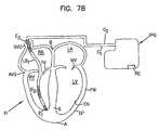
- FIG. 1is a schematic cross-sectional view of the heart showing relevant anatomical features and schematically showing a catheter with pacing electrodes in the right ventricle and a subcutaneously placed implantable pulse generator;
- FIG. 2is the view of FIG. 1 showing electrodes in contact with a septal wall
- FIG. 2Ais a cross-sectional view of an electrode lead showing a mechanism for attachment of an electrode to a septal wall;
- FIG. 3is the view of FIG. 1 showing an electrode lead formed, in part, from shape memory alloys for urging electrodes against a septal wall;
- FIG. 4is the view of FIG. 1 showing a further embodiment of an electrode lead for urging electrodes against a septal wall;
- FIG. 5is the view of FIG. 1 showing electrodes on a septal wall and energized by wireless transmission;
- FIG. 6is the view of FIG. 5 showing electrodes embedded within the septal wall
- FIG. 7is the view of FIG. 4 showing the lead of FIG. 4 with multiple electrodes urged against the septal wall;
- FIG. 7Ais the view of FIG. 1 showing a conventional active fixation lead with a helix for attachment of the tip electrode to a septal wall;
- FIG. 7Bis the view of FIG. 1 showing a shocking electrode
- FIG. 8is a view, taken in cross-section, of right and left ventricles of a heart showing the electrodes of FIG. 1 (without showing the lead body) energized to create electromagnetic fields;
- FIG. 9is the view of FIG. 8 showing the field shifted toward the left ventricle in response to repositioning of leads;
- FIG. 10is the view of FIG. 8 showing the field distorted toward a free wall of the left ventricle by influence of an external reference electrode;
- FIG. 11is the view of FIG. 9 with a reference electrode placed within the left ventricle;
- FIG. 12is the view of FIG. 14 with an external electrode placed on the epicardial surface of the heart;
- FIG. 13is a view with an external electrode placed within a coronary sinus
- FIG. 14is the view of FIG. 9 with fields distorted to be biased toward the left ventricle by the addition of dielectric material on a side of the electrodes of FIG. 9 ;
- FIG. 15shows a field distorted towards an upper end of the free wall in response to a reference electrode in a first position
- FIG. 16is the view of FIG. 15 with a reference electrode switched to a second position
- FIG. 17is the view of FIG. 15 with a reference electrode replaced by two polarized electrodes
- FIG. 18is a graphical representation of pulsed waveforms to be applied by first and second electrodes of the various embodiments
- FIG. 18Ais a view similar to that of FIG. 18 showing alternative waveforms
- FIG. 18Bis a view similar to that of FIG. 18 and showing two electrodes creating two separate fields to a reference electrode;
- FIG. 19is an electrical schematic for a portion of a pacing output desired in a pulse generator with programmable pacing configurations
- FIG. 20is a side elevation view of a patient's head and neck showing application of the present invention to applying a pacing signal to a vagus nerve;
- FIG. 21is a system for determining optimal placement of the electrodes
- FIG. 22is a view showing the spacing of two electrodes
- FIGS. 23A , 23 B, 23 C and 23 Ddepict a graphical representation of pulse to be applied by the electrodes of the various embodiments
- FIG. 24is diagram of a directable/adjustable catheter-type device useful for delivering certain pulsed waveforms
- FIGS. 24A , 24 B, 24 C and 24 Ddepict a graphical representation of pulsed waveforms to be applied by the electrodes of the various embodiments
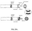
- FIGS. 25A and 25Billustrate catheter arrangements useful with the various embodiments discussed herein;
- FIGS. 26A , 26 B, 26 C and 26 Dillustrate example procedures for determining pacing-lead placement
- FIG. 27shows a cross-sectional view of a heart and the Hisian and para-hisian regions, consistent with an embodiment of the present invention
- FIG. 28shows a cross-sectional view of the heart marked with pacing sites
- FIG. 29shows pacing site locations on a 3-D depiction of the union of the AV node, the para-hisian and Hisian regions;
- FIG. 30shows pacing site locations on cross-sectional views of the heart.
- FIG. 31shows an example circuit for providing various stimulation profiles.
- the present inventionis believed to be applicable to a variety of different types of devices and approaches, and the invention has been found to be particularly suited for approaches to pacing of the right and left ventricles from a lead in the right ventricle.
- the inventionis used to facilitate mechanically and/or electrically synchronous contractions for resynchronization (possibly due to conduction abnormalities such as LBBB) where the left ventricle has regained its ability to rapidly contract and/or to synchronize contractions of cardiac muscle of the septum and respective free wall(s). While the present invention is not necessarily limited to such applications, various aspects of the invention may be appreciated through a discussion of various examples using this context.
- heart functioncan be improved by pacing and/or mapping by delivering pulses to a cardiac site, where the heart function is indicated or measured, e.g., by QRS width, fractionation, late LV activation timing, mechanical synchronicity of free wall and septal wall, effective throughput/pressure, and/or by any combination thereof.
- Certain methods and specific aspects consistent with such embodiments of the present inventionconcern directing a catheter-type device for delivering pulses to a cardiac site where the improved heart function involves: determining a pacing (voltage) threshold, beyond the capture threshold, to improve heart function; delivering pulses of opposite polarity to achieve such heart-function improvement; bi-ventricular pacing from a lead in the right ventricle for such improved heart function; delivering pulses of opposite polarity at a site near the His bundle; electrode-based His-pacing, without penetrating the myocardium; generating and/or delivering multiple pacing profiles, e.g., by iterating through different pacing profiles, including a pacing profile that delivers pulses of opposite polarity and another pacing profile; delivering a pacing profile to generate a synchronous contraction of the septal wall and free wall of the LV from a RV (right-ventricle) pacing location; and treating one or more of distal LBBB (left bundle branch block) and/
- Various embodiments of the present inventioninclude stimulation catheters, systems and methods that employ two or three electrodes.
- the most distal two electrodesare located at the tip of the catheter.
- An optional third electrodecan be located in a number of places, such as on the lead body some distance from the first pair or even located between the pairs.
- His bundle pacing and/or para-Hisian pacingcan be used to treat patients exhibiting a variety of cardiac abnormalities previously thought to be unsuitable for His bundle pacing (e.g., large QRS complexes due to distal left bundle blocks or diffuse left bundle blocks). It has also been discovered that implantation complexities (e.g., duration and/or invasiveness) can be beneficially affected by the use of specific devices, systems and placement methods.
- a specialized stimulation profileis used to capture a synchronous contraction of the left and right ventricles.
- the stimulation profileis provided to a lead in the right ventricle.
- the lead placement and stimulation profileare selected in response to sensed heart function during the pacing.
- the lead placement and stimulation profileare determined based upon more than whether the placement/profile results in capture (e.g., QRS width or late activation site timing). In certain instances, this can result in pacing voltages/profiles not otherwise believed to be desirable (e.g., voltages derived from criteria other than the capture threshold and/or His bundle pacing without penetrating the surrounding (fibrous) tissue with a pacing lead).
- Combined pacing of the right ventricle and right atriumhas been performed by advancing two electrode leads through the superior vena cava into the right atrium. The first of these terminated at one or more electrodes which were attached to the endocardium of the atrium. The second lead (also having one or more electrodes) was advanced into the right ventricle with the electrode attached to the endocardium of the right ventricle.
- electrical pulsesare used to disrupt a contraction of the heart. This may be effective at reducing the heart rate by disrupting the abnormally fast pulses generated by cardiac dysfunction tissue.
- CHFCongestive heart failure
- This conduction systemincludes the A-V node (heart tissue between the atria and the ventricles that conducts contractile impulses from the atria to the ventricles), the bundle of His and the Purkinje fibers.
- the sinus nodecreates the synchronized neurally-mediated signal for cardiac pacing.
- These signalsare conducted by the specialized fibers comprising the A-V node and the bundle of His (extending along the length of the septum) and further conducted to the muscle of the heart through the Purkinje fibers.
- the Purkinje fibersoriginate in the septum and extend through the apex of the heart and to the exterior walls of the heart including into and up the free wall of the left and right ventricles.
- the signal flow from the A-V node to the free wall of the left and right ventriclesis rapid to ensure the free wall and septum contract in synchrony.
- a stimulating signalmay flow to the free wall in about 70-90 milliseconds. In patients with conduction abnormalities, this timing may be significantly delayed (to 150 milliseconds or more) resulting in asynchronous contraction.
- the conduction path through the Purkinje fibersmay be blocked.
- the location of the blockmay be highly localized (as in the case of so-called “left bundle branch block” or LBBB) or may include an enlarged area of dysfunctional tissue (which can result from infarction).
- LBBBleft bundle branch block
- LBBBleft bundle branch block
- all or a portion of the free wall of the left and/or right ventriclesis flaccid while the septum is contracting.
- the contraction force of the free wallis weakened.
- CHF patientscan be treated with cardiac pacing of the left ventricle.
- cardiac pacingincludes applying a stimulus to the septal muscles in synchrony with stimulation applied to the muscles of the free wall of the left ventricle. While infracted tissue will not respond to such stimulus, non-infracted tissue will contract thereby heightening the output of the left ventricle by re-synchronizing the contraction. Accordingly, treatment of CHF is often directed re-synchronization of the myocardium, whereas other ventricular pacing solutions, such as tachycardia and bradycardia, treat heart rate issues.
- the prior arthas developed various techniques for accomplishing left ventricle stimulation. For various reasons the techniques may not be ideal. For example, such pacing may result in wide QRS complexes or emboli formation. Thus, endocardial-positioned electrodes in the left ventricle are avoided. However, electrodes can be placed on the epicardial surface of the heart through surgical placement. The epicardial electrodes are positioned on the free wall of the left ventricle and are paced in synchrony with electrodes placed near the septum in the right ventricle.
- epicardial electrodesrequire a surgical placement, the patient is subjected to two procedures: percutaneous placement of right ventricle electrodes (normally performed in a catheter lab by an electrophysiologist); and surgical placement of epicardial electrodes on the left ventricle (normally placed by a cardiac surgeon in a surgical suite). Such dual procedures are a burden on medical resources.
- Percutaneous procedureshave been developed for placement of an electrode to stimulate the free wall of the left ventricle.
- an electrode leadis advanced through the coronary sinus.
- the coronary sinusextends from the right atrium and wraps around the heart on or near the epicardial surface and partially overlies the left ventricle free wall.
- the electroderemains positioned in the coronary sinus overlying the left ventricle free wall with the lead passing through the coronary sinus and through the right atrium to the implantable pulse generator.
- a coronary sinus electrodeis frequently less than optimal.
- the portion of the free wall most directly influenced by the electrodeis the tissue directly underlying the coronary vein at the location of the electrode. For many patients, this may not be the location of the free wall that benefits the most from a stimulating therapy. Accordingly, the resulting therapy is sub-optimal.
- some patientsmay have an extremely small-diameter coronary sinus or the coronary sinus may have such a tortuous shape that percutaneous positioning of an electrode within the coronary sinus is impossible or very difficult.
- advancing a lead from the right atrium into the coronary sinusis extremely time-consuming. Even if successful, such a procedure consumes significant health care resources (including precious catheter lab time).
- U.S. Pat. No. 6,643,546 B2 to Mathis et al. dated Nov. 4, 2003describes a lead with an array of electrodes along its length.
- the leadis placed in the right atrium and extended through the right ventricle, along the septal wall, and into the pulmonary artery.
- the conceptrequires that multiple electrodes from the array be pulsed simultaneously at significantly high voltages to produce an adequate electrical field to stimulate the LV septum.
- the current output from the pulse generator and batterywill be very high due to the multiplicity of electrodes and high pacing voltages. Such high output will cause a clinically unacceptable product lifespan and may facilitate electrode corrosion and/or dissolution issues.
- the present inventionis directed to a left ventricle pacing system and method which does not require epicardial pacing electrodes or pacing electrodes in a coronary sinus or a coronary vein.
- the present inventionincludes electrodes in the right ventricle near the septal wall. These electrodes create a pulsed electrical field which stimulates both the septum and at least a portion of the free wall of the left and right ventricles. The present invention achieves these objectives without requiring excessive energy demands or power consumption.
- the aspects of the present inventionare directed to a method and apparatus for providing right-ventricle stimulation to re-synchronize a contraction of the musculature of the septum and free wall of the left and right ventricles to create coordinated contraction of the septum and free wall.
- Careful placement of the stimulating electrodes in the right ventricleis used to produce synchronous contractions of the left and right ventricles.
- the right ventriclemay be captured along with re-synchronization of the left and right ventricles from a single stimulus point or while maintaining the synchrony of the activation and contraction of the left and right ventricles (in the case that the patient required pacing and did not have an asynchronous contraction without pacing).
- patients that have an asynchronous contraction of the heartcan be resynchronized.
- pacing for patients having bradycardia, tachycardia or other rhythm managementmay be improved by improving upon the asynchronous contraction that often occurs due to the electrical impulse artificially introduced that is not propagating through the normal conduction system of the heart (His-Purkinje system).
- an electrodeis carefully placed at the His bundle site (“His Pacing”) by screwing in the electrode to get into or beside the bundle itself or by positioning the electrode at a site where the bundle gets to the endocardial surface (denoted supra as EN).
- His PacingPrevious His-pacing efforts (to maintain synchronous contractions that would be otherwise lost due to conventional RV pacing for rate support) have been very burdensome largely because finding this very small region in the right ventricle has been very difficult, and the effort is generally time-consuming, expensive and extremely complex even with modern tools and imaging techniques. Further complicating such procedures is the lack of knowledge regarding the long-term stability of placing a lead in this location.
- Pacing the distal segment of the His bundlehas also been shown to remove left bundle block (LBBB) in patients with a proximal lesion of the bundle.
- His pacingis currently contraindicated in patients with a distal lesion of the His bundle or with an intraventricular conduction defect (IVCD), in patients with diffuse peripheral block (at the distal His or diffuse in the Pukinje fibers), and in patients with advanced HF (NYHA class II to IV) and conduction defects.
- IVCDintraventricular conduction defect
- His pacingis used only in a very small subset ( ⁇ 0.01%) of the patients that require ventricular pacing for either Sick Sinus Syndrome, AV block or other Bradyarrhythmia indications by an extremely small group of physicians.
- Xstim waveforma waveform herein referred to as a Xstim waveform, where two pulses of opposite polarity are applied.
- the Xstim waveformgenerally speaking, is the application of the two pulses of opposite polarity at the same time, or nearly the same time, such that both pulses are associated with the same capture (beat) of the heart.
- the pacing regionis located near the location where the His bundle passes close to the endocardial surface of the right ventricle. But in patients with more diffuse block and heart failure, it may move down in the septum towards the apex of the right ventricle. It has also been discovered that careful selection of the waveform may allow for effective pacing using lower voltages, thereby simplifying the design of the output circuits in the pacemaker and the delivery electrodes. It has further been discovered that the desired pacing effect can also be achieved by a single pulse of sufficient amplitude, usually much higher than the amplitude required by the Xstim waveform, and therefore presenting a much higher risk of diaphragmatic and/or phrenic nerve stimulation. It has further been discovered that the amplitude required to achieve the effect is more often lower when that pulse is of anodal nature versus a negative pulse (referenced to the body).
- each electrodemay be selectively and independently used to stimulate a synchronous contraction.
- the voltages for each electrodeare varied to determine the voltage threshold necessary to produce ventricular capture.
- the voltage thresholdcan be determined using criteria other than (or in addition to) whether ventricular capture is produced (e.g., improved heart function).
- Low average stimulation voltage and currentmay be obtained by selecting the electrode that has the lowest effect threshold (effect refers to resynchronization effect or to maintaining synchrony of the contraction during pacing effect).
- aspects of the present inventionare directed to improving heart function as indicated by one or more of several measurable characteristics.
- the discussion and illustrations presented in connection with FIGS. 21-50provide examples and related results for one or more of these and other aspects of the present invention. These aspects can be implemented in various combinations. To fully appreciate some of these aspects and the related discoveries, the following discussion of FIGS. 1-20 presents related discussion as well as various features that are optional to other embodiments, such as those illustrated and discussed in connection with FIGS. 21-50 .
- FIG. 1illustrates the invention in practice with one such lead.
- the terms “left” and “right”are used herein with reference to the patient's perspective.
- the terms “upper” and “lower” and similar terms such as “up” or “down”are used with reference to the base B of the heart being high and the apex A of the heart H being a lower end.
- FIG. 1illustrates approaches for pacing of the right and left ventricles from a lead in the right ventricle in a manner consistent with the above discussed aspects.
- heart functioncan be improved by pacing and/or mapping to delivering such pulses to a cardiac site.
- Such pacing/mappingcan also be used to determine a pacing (voltage) threshold, beyond the capture threshold, to improve the heart's function.
- Such an approachcan also be used to provide bi-ventricular pacing from a lead in the right ventricle for such improved heart function.
- a patient's heart His schematically shown in cross-section.
- the heart Hincludes the upper chambers of the right atrium RA and left atrium LA.
- the lower chambersare the right ventricle RV and left ventricle LV.
- the superior vena cava SVCis shown.
- the mitral valve MVseparating the left atrium LA from the left ventricle LV
- the tricuspid valve TVseparating the right atrium RA from the right ventricle RV
- the septum Sseparates the right and left ventricles RV, LV and the free wall FW of the left ventricle LV is separately labeled.
- the surface of the heart wall tissue opposing the chambersis the endocardium and is labeled as EN.
- ENThe exterior surface of the heart
- EPThe exterior surface of the heart
- coronary vessels of the heart or the pericardium surrounding the heart Hare not shown.
- FIG. 1includes an electrode lead in an embodiment where signals are delivered via a dual (inner and outer) sheath catheter and shown as having a lead body LB 1 and exposed electrodes E 1 and E 2 .
- the first electrode E 1is positioned near the distal tip of the lead body LB 1 .
- the second electrode E 2is positioned more proximally on the lead body LB 1 .
- an attachment mechanism AM(such as a passive fixation design with tines or an active fixation design with a metallic helix) is shown for securing the first electrode E 1 to the musculature of the heart H.
- the spacing of electrodes E 1 , E 2could be greater or smaller than that of convention pacing electrodes permitting positioning of the first electrode E 1 at the apex of the right ventricle RV and the second electrode E 2 in the right ventricle RV near the tricuspid valve TV. It is noted that conventional leads with convention spacing have been used with the first or distal electrode attached to the septum (e.g., by a helix attachment HA as shown in FIG. 7A ).
- the position of electrodes E 1 and E 2is determined by monitoring and analyzing the effectiveness of the pacing.
- an electrocardiogramECG
- the electrode positionmay be incrementally adjusted and the feedback from the ECG can be compared for each position.
- the QRS widthis used in such a comparison.
- Another parameter that may be consideredincludes the angle of the vectocardiogram.
- the analysis of the vectocardiogrammay be viewed in terms of normalization of the vectocardiogram.
- the efficiency of the contractioncan be ascertained by monitoring the coronary sinus electrogram to determine the time delay that the activation wave front has between the pacing stimuli (or the resulting QRS complex) until a left ventricular activation is detected at the coronary sinus or any other (late activation) structure of the left ventricle. This may be accomplished using an electrophysiology-style catheter or any other catheter with one or more electrodes close to its tip. In one instance, the goal is to minimize the time delay.
- the lead body LB 1is flexible and includes a bio-compatible, electrically insulating coating surrounding first and second conductors C 1 , C 2 separately connected to the first and second electrodes E 1 , E 2 .
- the lead bodiesare broken at a line at the SVC to reveal the internal conductors C 1 , C 2 extending to an implantable pulse generator IPG.
- the conductors C 1 , C 2are contained within the material of the lead body LB 1 along their length.
- implantable pulse generator IPGis intended to include pacemakers, implantable converter defibrillators (ICD) and cardiac resynchronization therapies (CRT), all known in the art.
- the proximal end of the lead bodyterminates at a pin connector (not shown) as is customary.
- the pin connectorhas exposed electrical contacts uniquely connected to each of the conductors C 1 , C 2 .
- the pin connectormay be connected to the pulse generator IPG so as to be releasable and with the exposed contacts making electrical connection with unique contacts of the circuitry of the pulse generator IPG.
- the prior artcontains numerous examples of cardiac leads for placement in a chamber of the heart where the leads have, as described above, two or more electrodes spaced along a length of the lead, attachment mechanisms such as passive or active fixation and conductors and connector pins as described.
- the current inventionis not limited to pacing leads only, but rather is equally deployable with prior art ICD leads where it is customary to contain at least two electrodes in the RV.
- Such leadsare selected of biocompatible material and treated (such as sterilized) for chronic placement in the patient.
- the implantable pulse generator IPGis a small metallic container sealed for implantation in the patient and protecting internal circuitry. Commonly, such pulse generators are placed subcutaneously (e.g. in a dissected space between the skin and muscle layers of the patient). For cardiac pacing, such pulse generators are positioned in the upper chest on either the left or right front side of the patient near a shoulder. However, placement need not be so restricted and such pulse generators could be placed in any convenient location selected by the physician.
- Pulse generatorscontain internal circuitry for creating electrical impulses which are applied to the electrodes after the lead is connected to the pulse generator. Also, such circuitry may include sensing and amplification circuitry so that electrodes E 1 , E 2 may be used as sensing electrodes to sense and have the IPG report on the patient's electrophysiology.
- the leadmay be introduced to the vasculature through a small incision and advanced through the vasculature and into the right atrium RA and right ventricle to the position shown in FIG. 1 .
- Such advancementtypically occurs in an electrophysiology lab where the advancement of the lead can be visualized through fluoroscopy.
- the pulse generatorcontains a battery as a power supply. With subcutaneous placement, replacement of a battery is possible. However, improvements in battery designs have resulted in longer-lasting batteries with the benefit of reducing the frequency of battery replacement. Alternatively, such batteries may be rechargeable in situ.
- the pulse generator circuitrycontrols the parameters of the signals coupled to the electrodes E 1 , E 2 . These parameters can include pulse amplitude, timing, and pulse duration by way of example.
- the internal circuitryfurther includes circuit logic permitting reprogramming of the pulse generator to permit a physician to alter pacing parameters to suit the need of a particular patient. Such programming can be affected by inputting programming instructions to the pulse generator via wireless transmission from an external programmer.
- Pulse generatorscommonly include an exposed contact on the exterior of the generator housing. Such pulse generators may also be partially covered with an insulator, such as silicone, with a window formed in the insulator to expose a portion of the metallic housing which functions as a return electrode in so-called unipolar pacing. In bipolar pacing, the window is not necessary. Most commonly, the electrode is connected by the circuitry of the housing to an electrical ground.
- the pulse generatormay be external and coupled to the electrodes by percutaneous leads or wireless transmission.
- a control of an implanted electrodeis known for phrenic nerve stimulation and is described more fully in a product brochure, “ATROSTIM PHRENIC NERVE STIMULATOR”, AtroTech Oy, P.O. Box 28, FIN-33721, Tampere, Finland (June 2004).
- the Atrostim devicesends signals from an external controller to an implanted antenna.
- External pacing devicesare typically used for providing temporary pacing therapy. Aspects of the current invention are also believed to have advantages for this application as critically-ill patients requiring emergency, temporary pacing may also suffer further from asynchronous cardiac contraction associated with conventional RV pacing. If desired, an external unit can be used to test a patient's suitability for the treatment. Patients who benefit from the therapy can then receive an implantable pulse generator for longer-term use.
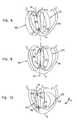
- FIG. 2illustrates a lead body LB 2 in the right ventricle RV with the electrodes E 1 , E 2 directly placed on the septal wall S and held in place against the septal wall through any suitable means.
- FIG. 2Aillustrates one embodiment for attachment of an electrode against the septal wall.
- the lead body LB 2is shown as having an internal lumen LU with a port PO near an electrode (e.g., electrode E 2 ).
- Any suitable attachment mechanism(such as a pigtail guide wire or an injected bio-adhesive) can be passed through the lumen LU and port PO to fix the electrode E 2 in abutment against the septal wall S.
- a guide cathetercould also be used in moving the implantable lead to assist in the mapping of the optimal location of the septum.
- FIG. 3illustrates the electrodes E 1 , E 2 against the septal wall S but without requiring an attachment mechanism. Instead, an intermediate region (IR) of the lead body LB 3 is formed of shaped memory material (such as nitinol) to assume an S-shaped configuration and urge the electrodes E 1 , E 2 against the septal wall S.
- shaped memory materialsuch as nitinol
- the lead body LB 4has two components LB a , LB b joined by an intermediate section IS which may be formed of any elastomeric material (such as a shaped memory material).
- the intermediate section (IS)is biased to urge the two components LB a , LB b into collinear alignment. With the intermediate section IS placed against the apex of the right ventricle (RV), the bias of the intermediate section IS urges the electrodes E 1 , E 2 against the septal wall S.
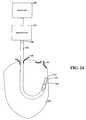
- FIG. 5illustrates the electrodes E 1 , E 2 individually placed on the septal wall S and not retained on a lead body.
- the electrodes E 1 , E 2may be energized in a pacing waveform by wireless transmission signals T 1 , T 2 from the implantable pulse generator (IPG).
- IPGimplantable pulse generator
- Wireless transmission from a controller to an electrodeis shown in U.S. Pat. No. 6,907,285 to Denker, et al., dated Jun. 14, 2004.
- the electrodes E 1 , E 2may be directly imbedded as microstimulators into the tissue of the septal wall S as illustrated in FIG. 6 .
- Microstimulators for implantation into human tissueare shown in U.S. patent application Publ. No. 2004/0153127 published Aug. 5, 2004.
- FIGS. 1-20illustrate aspects of the present invention similar to that discussed above in connection with FIG. 1 where certain of these figures show common characteristics.
- FIGS. 1 , 7 B and 8illustrate example leads and the associated electrical fields with both electrodes residing within the right ventricle with the distal electrode secured to the apex of the right ventricle, with FIG. 8 showing the ventricles RV, LV and a portion of the lead body LB 1 . While such bipolar leads are acceptable for use with the present invention, a wider spacing between electrodes E 1 , E 2 can increase the field but can sacrifice some sensing capability. This trade-off can be mitigated by use of a three-electrode lead in the right ventricle RV.
- Such a leadwould have a tip electrode and two ring electrodes, one located near the tip in the RV apex and one in the high part of the atrium, near the tricuspid valve.
- the sensingis performed between the tip and closer electrode. This will provide good so-called “near field” sensing and avoid so-called “far field” sensing of the atrium or skeletal muscles activity.
- the pacingcould be between the ring electrodes to the return electrode located distally to the heart (as will be described).
- Onecould also combine the tip and nearest ring as one electrode to the return electrode and the other ring electrode to the return electrode at the opposite polarity.
- a ring with a width of 4 mmis separated by a distance of 4 mm from a tip with a width of 4 mm.
- the pulse generator IPGwhich is common to FIGS. 1-7 b .
- the pulse generator IPGgenerates a first and a second pulsed waveform W 1 , W 2 applied, respectively, to the first and second electrodes E 1 , E 2 .
- FIG. 18shows such waveforms W 1 , W 2 of depicting signals generated by this illustrated IPG.
- the pulse duration (PD)is between about 0.1 to 2.0 milliseconds
- the amplitude Amay be 0.1 Volts to 10 or 20 Volts
- the time delay TD between pulsesis a targeting heart rate (e.g., 50 to 200 beats per minute).
- FIGS. 1-18Bshow examples of electrode placements (e.g., electrode E 1 ) at various positions along or near the septal wall.
- electrode E 1is attached to the mid- or upper-septum.
- the reference electrode REused in some but not all such embodiments of the present invention, is on the housing of the IPG and positioned subcutaneously near the right or left shoulder.
- the re-direction of the fieldmay also be useful in decreasing defibrillation thresholds for arrangement similar to that shown in FIG. 7B .
- large segmented (for flexibility) electrodes E 2 , E 3are shown in the superior vena cava SVC near the atrium RA and in the right ventricle to serve as shocking electrodes to defibrillate a patient.
- FIG. 9shows field lines useful for such stimulation and resulting from movement of the electrodes E 1 , E 2 from the interior of the right ventricle RV ( FIGS. 1 and 8 ) to the septal wall S. Such movement shifts the field lines toward both the septal wall S and the free wall FW of the left ventricle LV.
- reference electrode REin combination with the electrodes E 1 , E 2 in the right ventricle, provide effective pacing of the left and right ventricles LV.
- the reference electrode REdistorts the electromagnetic field otherwise created between the right ventricle electrodes E 1 , E 2 to urge an intensity of the electromagnetic field deeper into the septal wall S of the left ventricle LV. This may be due to creation of a third high current density spot (or spots) away from the two electrodes in the wall and towards the reference electrode at the point where the current flows between the electrode E 1 and the reference electrode RE and between the electrode E 2 and the reference electrode RE while coinciding in space and time.
- the reference electrodemay be physically attached to the housing of the implantable pulse generator IPG (and thereby having a neutral charge). Such an electrode RE is shown in FIGS. 1-7B . It will be appreciated that the reference electrode RE can be connected to the implantable pulse generator IPG by a conductor.
- the reference electrodecould be another common electrode that exists in the conventional pacing or ICD system, such as an electrode in the atrium or a defibrillation coil electrode situated in the SVC, RA or RV.
- the consequence of the reference electrode REmay have a deforming effect on the electromagnetic field generated between the first and second electrodes E 1 , E 2 .
- Thisis illustrated in FIG. 10 by distorting the left field lines LFL toward the septal wall S and free wall FW of the left ventricle LV.
- the right field lined (RFL)are compressed toward the axis FA to alter the field from the symmetric presentation of FIGS. 8 and 9 to the asymmetric presentation of FIG. 10 with the field biased toward the septal wall S and the free wall FW of the left ventricle LV.
- Chronic pacing with an anodal electrodeis believed to create an exit (anodal) block, meaning that the capture thresholds of the cardiac tissue may go beyond the voltage range of the pulse generator. When this happens the beneficial effect of the stimulation is lost. Since capture is often lost, the patient's life may be placed at risk by such an event.
- the polarity of the charged pulses seen at electrodes E 1 and E 2may be alternated. This can be particularly useful for avoidance of anodal blocking (gradual rising of the threshold voltage necessary to capture and re-synchronize the myocardium).
- Such polarity swappingmay be implemented using a suitable periodicity.
- the polarity of the electrodesis switched after several hours of operation.
- this polarityis alternated beat by beat, so that the net charge delivered to the tissue over two beats would be zero.
- the frequency of alternationcould be varied in a very wide range and still accomplish the goal of balancing the charge delivered, to allow for the net charge delivered on average to be near zero. This can be useful for avoiding the issue of anodal block and minimizing the risk of electrode dissolution and/or corrosion.
- the optimal lead locationcan be determined with the assistance of the surface ECG parameters (e.g., QRS width and/or activation vectors).
- the positioning of the reference electrode REmay be directly on the housing of the implantable pulse generator IPG or may be separate from the internal pulse generator as previously mentioned.
- the reference electrode REcan be placed in the left ventricle ( FIG. 11 ) (or in the tissue of the free wall FW as shown in phantom lines in FIG. 11 ), on the epicardial surface EP ( FIG. 12 ) or in the coronary sinus CS ( FIG. 13 ).
- Positioning the reference electrode RE relative to the heartcan affect the distortion of the field in the area of the left ventricle free wall FW subject to pacing. Particularly for a subcutaneously placed reference electrode (which is preferred to minimize the invasive nature of the procedure), the electrical conduction path from the right ventricle RV to the reference electrode will vary considerably between patients.
- the direction of field distortionmay alter the region of the left ventricle LV subject to pacing.
- FIG. 15illustrates the reference electrode RE 1 placed high relative to the heart, resulting in a distortion of the field toward the upper end of the left ventricle septum and free wall FW.
- FIG. 16illustrates placement of a reference electrode RE 2 lower relative to the heart and to deflect the intensity of the field toward the lower end of the left ventricle septum and free wall FW.
- the reference electrodecould be a single electrode, multiple electrodes could be provided for subcutaneous placement and each connected by a switch circuitry SW of the implantable pulse generator as illustrated in FIGS. 15 and 16 .
- the patient's responsecan be noted with each of the several reference electrodes RE 1 , RE 2 separately connected to the ground or housing of the implantable pulse generator. The patient can then be treated with the electrode showing the most effectiveness for the particular patient. Further, over time, a patient's response may change and the implantable pulse generator can be reprogrammed to select any one of the other reference electrodes as the switched electrode.
- the catheter LB 5 within the right ventriclecan have multiple electrodes along its length (as shown in FIG. 7 ). Individual pairs of these electrodes E 1 -E 4 can be switched on or off over time so that the appropriate pair of electrodes within the right ventricle is selected for optimized left ventricular pacing.
- FIG. 14illustrates how the field can also be distorted by dielectric material DM placed on a side of the electrodes E 1 , E 2 opposite the septal wall S.
- the dielectric material DMresult in a distortion of the electrical field biasing the left field lines LFL toward the septal wall S and the free wall FW.
- this configurationwill work even better with a reference electrode which will enhance the benefit.
- Various techniques for movement of the electrodes E 1 , E 2 against the septal wall Sare disclosed.
- the reference electrodeis grounded to the housing of the implantable pulse generator.
- FIG. 17illustrates an alternative embodiment where the reference electrode includes two active electrodes AE 1 , AE 2 external to the heart.
- the active electrodes AE 1 , AE 2are paced with pulsed waveforms which are polar opposites of the waveforms on electrodes E 1 , E 2 . This creates dual uni-polar field in addition to the left field lines LFL previously described.
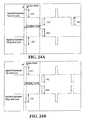
- the amplitude of the waveforms from FIG. 18is shown in phantom lines as the battery voltage applied to the four poles on the left of FIG. 19 to charge the two pacing capacitors C 1 and C 2 .
- Details of the charging circuitry as well as other controlling circuitry for pacing and sensingare omitted for ease of illustration. In one instance only capacitor C 1 is charged for the pacing output, whereas C 2 is not charged.
- Capacitor C 3 and C 4are optionally implemented for coupling the pacing output to the patient.
- the output waveform from FIG. 18 with the same amplitude and simultaneous timingis assumed for the design schematic in FIG. 19 .
- a switch S 1permits selection between unipolar pacing and pacing Xstim or similar pacing (by contact with switch pole A 1 ) or bi-polar pacing (by contact with switch pole A 2 ). Selection between bi-polar pacing or Xstim pacing is made by applying a digital signal with the timing information as shown in FIG. 18 to either T 1 or T 1 and T 2 , namely to either toggle the switch S 5 or S 2 and S 5 simultaneously. An AND gate is used to allow the close of the switch S 2 only for pacing according to Xstim. Switches S 3 and S 4 permit re-neutralization of the pacing charges at the patient-electrode interface.
- the devicemay be programmable to achieve either conventional bipolar or unipolar stimulation or to achieve the Xstim stimulation through an external programmer or controlled automatically by the device.
- the selectioncan be based on user preference or be driven by physiological factors such as widths of the patient's QRS complex or the conduction interval between the stimulus to a far away region in the heart.
- switching between the Xstim pacing and other pacingcan also be determined by the percentage of pacing with a preference for a higher percentage with the pacing of the present invention.
- the switching from a first type of pacing to the Xstim pacingcan be used when there exists an exit block or the pacing electrode is located in infarcted myocardium when first type pacing does not capture (effect the depolarization of) the myocardium at the high output level.
- the automatic determinationcan be effected through the deployment of any automatic capture detection technology including, but not limited to, electrical sensing of the heart.
- wireless network-enabled switching function for therapy optimizationcan also be implemented with the present invention. In such cases, certain patient physiologic data are gathered by the implantable device and sent to a remote server/monitor through a wireless communication network.
- the stimulus voltageis consistent with discharge of an RC circuit as shown by FIG. 23A . This may be accomplished by connecting the electrode(s) to the anode (and/or cathode) of a charged capacitor.
- the stimulus voltageis consistent with the discharge of two sets of two capacitors in succession, as shown by FIG. 23B .
- Thismay be accomplished by connecting the electrode(s) to the anode (and/or cathode) of a first charged capacitor and then to a second charged capacitor.
- This embodimentmay be useful for reducing the voltage swing of the pulse, thereby altering the delivery of energy during the active stimulation period and potentially minimizing the voltage required to achieve the desired effect.
- a first set of capacitorscould be connected to electrode E 1 and a second set could be connected to electrode E 2 .
- the voltages provided to the electrodescould be of opposite polarity as in the standard Xstim waveform or could be alternated as described above to make the net charge delivered to the electrodes equal to zero.
- FIG. 23COther embodiments may allow for the use of two sets of three or more capacitors as shown by FIG. 23C .
- various voltage-regulation techniquesmay be used to provide a constant voltage, or square waveform, as shown by FIG. 23D . This may be useful to provide a more constant delivery of voltage during the active stimulation period. In some instances, such waveforms may allow the reduction of voltage thresholds required to achieve the desired effect.
- one of these groups of three or more capacitorscould be connected to electrode E 1 and the other group of three capacitors could be connected to electrode E 2 .
- the two groupsmay be charged to opposite polarities, as in the standard Xstim waveform.
- the groupsmay alternate between electrodes E 1 and E 2 , as described above, resulting in the net charge delivered to the stimulus point by the electrodes equal to zero.
- the same effectcould be achieved by using an anodal pulse delivered through the capacitive discharge of one, two or three or more capacitors to one of the electrodes with a larger amplitude voltage.
- This anodal pulsewill be alternatively connected to one of the stimulating electrodes in one beat and to the next electrode on the next beat.
- the alternating frequencycould be lower.
- the anodal capacitive dischargecould be alternatively connected to electrode E 1 and then to E 2 every 2 to 10,000 beats. If the alternating charges are equally distributed, the net charge delivered may be kept very close to zero.
- the physicianmay place an intraventricular pacing lead in a preferred location (locus) that maintains the effect (using one of the previously-described methods, making each electrode alternatively the anode) when either of the electrodes is the anodal electrode.
- the pulse width of the various embodimentsmay be varied according to the desired treatment and/or in accordance with the response of the particular patient.
- Example pulse widthsmay range from 0.05 ms to 5.0 ms.
- resynchronizationis achieved by presenting a pulsing signal (waveform) to a sweet spot (e.g., locus in the septal part of the RV endocardium) and, every so often, modulating the signal such as by changing its polarity.
- a pulsing signalwaveform
- a sweet spote.g., locus in the septal part of the RV endocardium
- modulating the signalsuch as by changing its polarity.
- the pulsing signalis presented by an electrode and a reference voltage (e.g., a node at the can and/or at the body under treatment)
- the signalcan be modulated in a similar manner by adding and/or skipping pulses.
- the power consumption of the pacing devicecan be an important consideration. While not bounded by theory, it is believed that different pacing profiles can be particularly advantageous to controlling pacing power. For example, during times that the pulses applied to each electrode overlap, the effective voltage seen between the electrodes is believed to be equal to that sum of their amplitudes.
- the pulses shown by the figuresare applied to the ring and tip electrodes, such as those illustrated in FIG. 22 .
- the polarity of the voltages, as relative to each other and/or a reference voltage,may be alternated periodically (e.g., beat by beat or every N pulses). As discussed above, such alternating may be particularly useful for mitigating anodal blocking. Moreover, alternating of pulses may also mitigate corrosion of the electrodes.
- the first electrode E 1has positively charged pulses only.
- the second electrode E 2has negatively charged pulses timed to coincide with the positively charged pulses of the positive electrode E 1 .
- direct current (DC) pulsesare preferred, the electrodes E 1 , E 2 could be energized with alternating current pulses with the signals to the electrodes E 1 , E 2 out of phase such that the positive pulses on the first electrode E 1 coincide with negative pulses on the second electrode E 2 and negative pulses on the first electrode E 1 coincide with positive pulses on the second electrode E 2 .
- an electrical fieldis created between the electrodes E 1 , E 2 with a field axis FA ( FIG. 8 ) extending in a line between the electrodes E 1 , E 2 .
- the fieldis symmetrical about the field axis FA and is represented by field lines illustrated in the drawings as left field lines LFL to the left of the axis FA (with left being from the patient's perspective) and right field lines RFL.
- the field linesrepresent the intensity of the electrical field. The intensity diminishes rapidly as a function of the distance from the field axis FA.
- a voltage potential across the electrodesis set at a substantially high level.
- high voltagesare not practical in a pacing electrode and are more normally associated with defibrillating treatments.
- such voltagesmay cause phrenic nerve and/or diaphragmatic stimulation and may also cause a significant drain on a battery that would require impractical frequency of battery replacement.
- FIG. 18illustrates an example waveform with electrodes E 1 , E 2 being simultaneously pulsed with opposite polarity.
- FIG. 18Aillustrates waveforms W 1 ′, W 2 ′ of similar structure to the waveforms of FIG. 18 but out of phase.
- the first set of pulse illustrated in waveforms W 1 ′, W 2 ′present a partial overlap duration OD (OD is a positive value).
- the third set of pulsesincludes pulses that are out of phase such that the leading edge of one pulse occurs after the end of the first pulse of the set (OD has a negative value).
- 18Aat least a portion of time includes a monopolar pacing from individual ones of the electrodes E 1 , E 2 to the reference electrode RE. This pacing creates out of phase monopolar fields F 1 , F 2 as illustrated in FIG. 18B .
- Values of ODcan range from the entire pulse length (e.g., around two milliseconds) to a negative value of several milliseconds (e.g., around negative two milliseconds).
- either of the negative or positive pulsescan lead the other pulse, respectively.
- the amplitudes of the two waveformsare shown to be equal, they need not be equal in practice nor do they necessary need be implemented as strict square waves.
- the ODcan be calculated accordingly.
- the ODmay be calculated from beginning or end of the rise/fall of each pulse, respectively.
- the ODmay be calculated from when each pulse reaches a certain voltage level, respectively, or once the pulse has maintained a certain voltage level for a period of time.
- FIG. 19illustrates a representative circuit in schematic format for a portion of a cardiac stimulation pulse generator that is capable of providing pacing output for either the conventional waveforms or Xstim waveforms as herein.
- the circuit of FIG. 19could be for an implantable pacemaker or any external stimulation system for diagnostic or therapeutic use.
- the stimulation devicehas three output terminals that are connected to three electrodes E 1 , E 2 , RE in the body. Electrodes E 1 , E 2 are positioned in the right ventricle RV with it being preferred that at least one of these electrodes be in direct contact with the septum S.
- the reference electrode REis an indifferent electrode which can be connected electronically to the housing of the implantable pulse generator IPG.
- the reference electrode REmay be an electrode directly on the implantable pulse generator or any other electrode for placement inside or outside of the heart as described above.
- the present inventioncan also be extended to the defibrillation therapy where high-energy pulses with various waveforms are delivered through electrode systems to treat tachycardia and fibrillation (both atrium and ventricle).
- the present inventionis believed to be able to achieve a lower defibrillation threshold due to better distribution of the electrical field, causing higher voltage gradient at least in certain parts of the heart compared to that by the conventional defibrillation configuration as seen in FIG. 7B .
- the present inventioncan be used to perform anti-tachy pacing where faster than conventional pacing pulse sequences are used to stop certain tachyarrhythmia. Aspects consistent with present invention are believed to provide wider coverage of the electrical field and the capability of capturing special conduction systems in the heart (both atrium and ventricle).
- the electrodes E 1 and E 2are positioned proximate to one another as shown in FIG. 22 .
- Thiscan be particularly useful for localizing the region in which the electrical stimulus (using one of the configurations described before) can achieve the desired synchronization or resynchronization effect.
- the electrodesmay have a width of around 4 mm and may be positioned within a distance D of about 5 mm from one another. In another example, the electrodes may be positioned within a distance D of about 2 mm or less.
- the selective placementmay be modified for a particular dysfunction and/or for a particular patient.
- the electrodesmay be positioned near the His bundle. Locating the electrodes near the His bundle may advantageously allow for capture of both the right and left ventricle. Moreover, resynchronization of the left (or right) ventricle may be possible even for cases of LBBB (or RBBB).
- FIG. 21shows a system for selectively placing the electrodes.
- the lead discussed in connection with FIG. 22may be used.
- the lead positionis adjusted through various methods via conceptual block 104 .
- the lead positionmay be monitored and location information may be provided to myocardium capture analysis block 102 .
- Myocardium capture monitor block 106monitors the effectiveness of the current lead position in capturing and re-synchronizing a contraction of the myocardium of the left and right ventricles.
- the monitor informationis provided to myocardium capture analysis block 102 , which processes the received information for the purposes of positioning the electrodes.
- monitor block 106uses ECG measurements to monitor myocardium capture and re-synchronization.
- Analysis block 102may analyze various factors of the far field measurements including, but not limited to, the QRS width (e.g. determined from a vectocardiogram).
- the ECG measurementsmay be supplied from a number of different inputs including, but not limited to, defibrillation coils, the can of the implantable device, an electrode of a pacing or sensing lead or an external ECG (or similar) device.
- monitor block 106may measure the amount of blood flow resulting from a contraction of the myocardium.
- the system of FIG. 21may also be used to adjust other re-synchronization parameters. For instance, the voltage levels and waveforms may be adjusted according to feedback from monitor block 106 and analysis from analysis block 102 . In particular it has been discovered that careful placement may allow for low voltages to be applied to the electrodes. In one embodiment, the pacing impedance of the lead and electrodes is low to allow for effective delivery of the pacing voltage. This may be useful for reducing the power consumption of the device and for reducing the voltages necessary to deliver the stimulus. By proceeding in this manner, (e.g., using low impedance and maintaining low voltage), phrenic nerve stimulation or diaphragmatic stimulation, both highly undesirable side effects of high pacing, may be avoided.
- the leadhas a screw with a short screw relative to screws used to reach the left ventricle or the His bundle. This allows for fixation of the lead until encapsulation and helps reduce mechanical problems associated with such attachments.
- the screwmay be made from a non-conductive material, thereby electrically isolating the attachment point.
- the screwmay be otherwise electrically isolated from the electrodes for delivering the pacing voltage even where the screw is made from a conductive material.
- a hookis used as the attachment mechanism.
- a T-baris used as the attachment mechanism.
- the reference electrodemay be optionally implemented to provide effective re-synchronization.
- the reference electrodeis used to provide a reference voltage derived from the in vivo voltage at a particular location. This reference may be used to reference the voltage provided at the stimulus location to the particular location. For example, the reference location may be taken at the can location or from a reference electrode located near the stimulus location. In another instance, no reference electrode is used.
- selective placement of the electrodesmay provide a number of unexpected advantages. More specifically, selective placement of the electrodes along the septum appears to provide re-synchronization of the left and right ventricles even for cases of LBBB where the lesion of the bundle would not be considered proximal. Furthermore, in many instances a large improvement has been seen in the level of synchrony in patients with LBBB and also in patients with moderate or advance HF and conductions defects including LBBB, RBBB and IVCD. For instance, locating the electrodes near an optimal location on the septum has been shown to produce smaller than expected QRS widths. Moreover, the threshold voltages necessary to capture the myocardium of the left and right ventricles or to produce the smaller than expected QRS widths (or indications of improved heart function) may be relatively small.
- FIG. 24shows an example of a sheath for use within the right ventricle 166 of the heart.
- the outer sheath 156is designed to be inserted through the mitral valve 158 and into ventricle 166 .
- Outer sheath 156may include a J-type bend as shown in the figure. In various applications, this advantageously facilitates the placement of electrodes 160 , 164 near the septum and/or the tricuspid valve 162 .
- one or more of the outer and an inner sheath 154may arranged to allow directional control of the sheath position (e.g., by allowing for the adjustment of their curvature).
- inner sheath 154is located within outer sheath 156 .
- Inner sheath 154may be adjusted, relative to outer sheath 156 , using adjustment mechanism 152 .
- the adjustment mechanism 152includes an adjustable track wheel or another similar mechanism.
- inner sheath 154may contain a pacing lead and/or a guide wire for additional stability.
- the adjustment of inner sheath 154may be accomplished through a number of different techniques. According to one such technique, the inner sheath is allowed freedom to advance through the outer sheath and to move along the septum. In another example technique, the inner sheath may be arranged to direct the lead placement (e.g., by allowing for the adjustment of its curvature).
- the inner sheath and/or the outer sheathmay have an electrode at their tip to use for pace mapping the locus for Xstim (following procedures discussed herein). Thus, facilitating the insertion of the chronic pacing lead.
- the inner and out sheathsmay be peelable so that the pacemaker lead is kept in place while the sheaths are removed.
- External pacing device 150provides electrical pulses to the electrodes 160 , 164 .
- the positioning of the electrodes 160 , 164may be adjusted and the effectiveness of each position may be monitored.
- Various examples of suitable monitoring techniquesare discussed in more detail herein.
- the adjustment mechanismincludes a number of fixed settings that can be reproduced. This allows for easily retrievable positioning of the electrodes 160 , 164 as correlated to the effectiveness of each position.
- the inner sheathmay be advanced along positional settings 1 through 10 and corresponding monitoring input may be used to determine which setting is preferred. The inner sheath may then be set to the preferred setting after a comparison between the results corresponding to each of the tested settings.
- each electrodemay be selectively and independently used to stimulate a synchronous contraction.
- the voltages for each electrodeare varied to determine voltage threshold necessary to produce ventricular capture or to produce improved heart function.
- Low average stimulation voltage and currentmay be obtained by selecting the electrode that has the lowest effect threshold (effect refers to resynchronization effect or to maintaining synchrony of the contraction during pacing effect).
- the outer and inner sheathsmay then be removed.
- a number of techniquesmay be used for such a removal. Using one such technique a guide wire is advanced through the sheaths and is used to hold the pacing lead in place while the sheaths are removed.
- the sheathsare constructed with a slit that allows for their removal from the pacing lead without significant force being applied to the pacing lead.
- the inner sheathmay function as a temporary pacing device connected to an external pacing source.
- the external pacing sourcemay advantageously be equipped with additional processing and display capabilities (relative to an implantable device, which is often limited due to battery life and physical size constraints) to assist in locating the proper placement location.
- the inner and outer sheathsmay be removed once the pacing lead is attached.
- the pacing leadmay also be connected to an implantable device.
- the external deviceoperates to provide a variety of different voltage waveforms and/or stimulus timings to the stimulus location. Feedback from an ECG or other device may be used to identify the preferred waveforms. The implantable device may then be uploaded with corresponding information for use in providing stimulus.
- the pacemakermay include a wireless port that allows an external interface to monitor and/or adjust the pacing functions. In this manner, the external device need not provide the stimulus through the external sheath. Instead, the implantable device may deliver the same set of stimulus using the wireless interface.
- the outer sheathmay be designed with a removable interface that is compatible with both the external pacing device and the implantable pacing device. This allows for the use of the external pacing device during placement of the electrode(s) and use of the same outer sheath with the implantable pacing. This may be particularly useful for reducing the size of the sheath, the cost of the device or for simplifying the procedure by avoiding the step of removing the outer sheath.
- FIGS. 24A-Ddepict additional waveform patterns that may be provided by an electronic circuit.
- FIG. 24Ashows pulses A 1 , A 2 and A 5 , which represent voltages applied to a first electrode (e.g., the voltage differential between the tip and the can), while pulses A 3 and A 4 represent voltages applied to a second electrode (e.g., the voltage differential between the ring and the can).
- Control logic in the pacemaker deviceallows for the individual adjustment of the voltage amplitude of the various pulses and for the adjustment of the pulse width or duration.
- the specific parametersmay be implemented by iteratively changing the waveforms and monitoring the effectiveness of the pulse.
- the selection of the ideal waveformmay be made by selecting the waveform that produces the smallest QRS width as measured by an ECG. While FIG. 24A depicts the pulse polarity as alternating each beat, it should be apparent from the discussion herein and from FIGS. 24B-C that this is merely one example of a possible pulse modulation scheme.
- one or more pulsesmay be withheld as shown by the lack of a pulse on the ring electrode that corresponds to pulse A 5 on the tip. In this sense the ring electrode pulse has effectively been withheld or skipped. In certain embodiments, either or both of the pulses may be withheld. Such withholding of pulses may be periodically implemented (e.g., once per every N pulses, or once every 20 minutes per 24 hours to allow heart to be conditioned by its own intrinsic contraction if the intrinsic heart rate is above a certain acceptable rate, such as 50 beats/minute). In another instance, the withholding may be responsive to feedback from a sensing electrode or ECG input.
- an example procedure for determining placement of a lead for pacinginvolves at least one repetition of pacing, sensing and repositioning using at least one lead adapted to deliver a pacing profile. While, not all of the data shown in the various figures was implemented as part of the experimental tests discussed herein, it is believed that the data shown is accurate.
- pacing of the heartis accomplished using a lead placed in the right ventricle and near the His bundle.
- the leadcan include two electrodes (and in some instances one) to deliver oppositely charged pulses. Heart functionality associated with the pacing then is monitored.
- the monitoringcan include one or more of the following examples, ECG readings (e.g., QRS width or fractionation), electrical activity of a late activation site in the left ventricle, mechanical contraction of the heart or measurement of the blood flow (e.g., the rate of change in pressure).
- ECG readingse.g., QRS width or fractionation
- electrical activity of a late activation site in the left ventriclee.g., mechanical contraction of the heart or measurement of the blood flow (e.g., the rate of change in pressure).
- the leadis repositioned and pacing and monitoring can be repeated.
- pacingcan be implemented in various ways. For instance, DDD (dual chamber) pacing can be implemented with or without a low atrial rate (e.g., around 50 beats per minute) and an AV delay of around one-half of the baseline or intrinsic AV interval.
- the DDD pacingcan also be modified to use a variety of different Xstim pacing profiles, non-Xstim pacing profiles and combinations thereof.
- a way to assess improved heart functioninvolves determining placement of a lead for sensing a late activation site in the left ventricle.
- the leadwhich is capable of sensing electrical activity in nearby heart tissue, is advanced through the CS (coronary sinus) until monitoring results from the lead represent activation of a late activating region.
- the leadcan be continuously advanced until activation of a distal electrode on the lead no longer occurs before any other electrode(s) on the lead. At this point, the current lead position can either be maintained or the lead can be slightly retracted.
- experimental dataprovides strong support that the beneficial effects on cardiac function provided by aspects of the present invention are due, at least in part, to His bundle stimulation.
- the datafurther supports that, unexpectedly, the His bundle may react more like a nerve than a myocyte with respect to responsiveness to electrical stimulation. This may be due in part to fibrotic encapsulation of the His bundle.
- Xstim pacingcan be attributed in part to the phenomena of anodal break stimulation in tissues with high directional anisotropy. It is also possible the success of Xstim pacing can be attributed in part to a phenomenon sometimes referred to as accommodation. Accommodation is an increase in voltage threshold necessary to produce depolarization of a nerve cell that occurs when the nerve is exposed to a non-zero voltage that is below the threshold voltage.
- Embodiments of the present inventionare directed to stimulation catheters, systems and methods that employ two or three electrodes and that can be used in connection with the various methods and systems discussed herein.
- the most distal two electrodesare located at the tip of the catheter.
- An optional third electrodecan be located in a number of places, such as on the lead body some distance from the first pair or even located between the pairs. The distance from the third electrode and the distal pair ranges from a few millimeters to a few centimeters.
- the cathetercan have a helical fixation structure which can be either a passive (non-electrical) or active (serving as one of the tip electrodes).
- the cathetercan be transvenously placed within the heart.
- the catheteris arranged such that once affixed to the heart tissue, the two pacing electrodes are in direct electrical contact with the cardiac tissue once.
- Experimental datasuggests that such features can be useful for providing low and stable thresholds during standard pacing. It has also been observed that two pacing electrodes in contact with the wall can be useful in finding a stimulation region in the right ventricle that depolarizes the heart in a manner very similar to the normal activation sequence created by the normal intrinsic (originating in the sinus node) activation propagating through the His-Purkinje system.
- FIG. 25AExample embodiments can be implemented where the two stimulating electrodes are in direct contact with the heart tissue.
- Example embodimentsare depicted in connection with FIG. 25A . These examples are not intended to exclude other possible implementations accomplishing similar results.
- one or more small porous conducting dotsmay be attached to the ring electrodes to increase the microscopic surface area (effective surface at the reactant level of physical interaction), and the helix electrode may be coated with material(s) to also increase the microscopic surface area.
- porous and raised portions of the electrodetake the form of any number of shapes (e.g., lines, circles, squares or zig-zags).
- scoring the electrodee.g., using a laser or etching).
- Nanostructurese.g., nanowires and/or nanotubes
- Such nanostructurescan provide significant increase in contact surface area.
- certain anti-inflammatory agentse.g., a steroid
- the configuration shown in FIG. 25Bcan be implemented in connection with methods and devices so as to provide sufficient contact surface area between the cardiac tissue and the electrode(s).
- Resistance between the electrode and the cardiac tissuecan affect signals (e.g., pacing or sensing signals) transmitted between the heart tissue (including the conduction system of the heart) and the electrode.
- signalse.g., pacing or sensing signals
- Increasing the surface area of the electrode(s) that contacts the heart tissuecan be particularly useful for detection of intrinsic cardiac depolarization signals.
- the circuit diagram shown in FIG. 25Brepresents a simple example implementation and various other implementations are possible.
- One implementation involving the use of such a circuitis as follows.
- electrodes 1 and 2are connected to one input of the sensing amplifier through a sensing switch that will be open during simulation to avoid short circuit but closed whenever sensing is needed.
- the other input of the sensing amplifiercan either connect to the stimulator CASE (e.g., for unipolar sensing) or to the optional electrode 3 , if available (e.g., for bipolar sensing).
- stimulation waveform(s)will be applied to the electrodes 1 and 2 .
- these waveformsare similar to those used with conventional catheters.
- Other applicationsemploy stimulation waveforms including, but not limited to, an Xstim waveform and/or two simultaneous opposite polarity stimulation pulses with reference to either the CASE or electrode 3 (if available).
- the various catheter arrangementscan be useful for implementing methods and achieving results discussed herein. For instance, the ability to individually address each electrode can be useful for pace mapping, such as that discussed in connection with FIG. 26A . Other aspects of the catheter arrangements allow for pacing to determine the target location as well subsequent chronic pacing at the determined location.
- FIG. 26Ashows an example procedure for determining placement of a lead for pacing according to an embodiment of the present invention. This procedure was implemented to place the pacing lead in connection with the experimental results provided hereafter.
- pacing of the heartis accomplished using a lead placed in the right ventricle and near the His bundle.
- the leadincludes two electrodes used to deliver oppositely charged pulses, such as with Xstim pacing.
- heart functionality associated with the pacingis monitored.
- the monitoringcan include one or more of the following non-limiting examples, ECG readings (e.g., QRS width or fractionation), electrical activity of a late activation site in the left ventricle, mechanical contraction of the heart or measurement of the blood flow (e.g., the maximum rate of change in left ventricular pressure).
- the improved heart functioncan be based upon a comparison of heart function without any pacing.
- pacinguses relatively high voltages (e.g., +/ ⁇ 5V) when pacing to determine lead location. This can be useful to ensure that the improved heart function is seen.
- pacing capturecan sometimes still be obtained without exhibiting significant improvement in heart function.
- the improved heart functioncan sometimes be an improvement over heart function resulting from use of the pacing lead and pacing profile rather than (or in addition to) the baseline and/or un-paced heart function.
- the leadis repositioned and pacing and monitoring steps 4526 and 4528 can be repeated as desired.
- the results of the monitoring stepcan be saved and correlated to the corresponding lead positions.
- the results of the monitoring step 4528are used to determine the proper placement for the lead. A few examples of the results of the monitoring step are shown by 4534 (QRS narrowing), 4536 (fractionation improvement), 4538 (late activation site earlier) and 4540 (mechanical function improved).
- the leadcan then be moved (back) to the lead position that is selected as a function of the monitoring results.
- the steps 4530 and 4532can be switched so that repositioning of the lead is done after evaluating the results of the monitoring step 4528 .
- the leadcan be repositioned until satisfactory results are detected. This can be particularly useful for not having to record and recreate lead positions previously paced. Instead, once satisfactory monitor results are found, the current lead placement can be used.
- FIG. 26Bshows an example procedure for determining placement of a lead for pacing according to an embodiment of the present invention.
- baseline heart functionis recorded (e.g., without Xstim pacing).
- a lead capable of delivering Xstim pacingis placed near the His bundle (i.e., near the root of the septal leaflet of the tricuspid valve in the right ventricle).
- Xstim pacingis delivered to the placed lead.
- the Xstim pacingis consistent with the waveforms depicted by and discussed in connection with FIG. 18 .
- the heart function associated with the Xstim pacingis recorded.
- step 4510If it is determined, at step 4510 , that Xstim pacing improves heart function (e.g., narrowing of the QRS, less fractionated QRS, improving timing of a late activation site, improved mechanical function or improved pressure function), the placement of the lead can be selected (and fixed) at step 4512 . Otherwise, the position of the placed lead can be adjusted at step 4514 and steps 4506 - 4510 can be repeated as necessary.
- heart functione.g., narrowing of the QRS, less fractionated QRS, improving timing of a late activation site, improved mechanical function or improved pressure function
- the determination step 4510can implemented using multi-lead ECG readings and a probe placed at a late activation site of the left ventricle (e.g., placing a lead near the posterior lateral wall of the left ventricle via a catheter inserted through the Coronary Sinus).
- DDD pacingcan be implemented as shown in step 4516 .
- the DDD pacingis implemented with a low atrial rate (e.g., around 50 beats per minute) and an AV delay of around one-half of the baseline or intrinsic AV interval (to allow for full capture and atrial tracking and ventricular pacing).
- the DDD pacingis modified to use a variety of different Xstim pacing profiles as shown in step 4518 .
- one or more of these profilescan be selected from the following non-limiting examples (discussed in terms of a lead with tip and ring electrodes for simplicity), in-phase pulses with positive voltage applied to the tip and negative voltage applied to the ring, in-phase pulses with negative voltage applied to the tip and positive voltage applied to the ring, out-of-phase pulses with opposite polarities applied to respective tip and ring electrodes.
- the pacing profilecan be adjusted in step 4524 .
- pocket stimulation effects, dry pocket or other effects due to chronic stimulationcan result in the threshold voltage increasing.
- shifting the overlap duration of the pulses (OD)can help compensate for such problems.
- the ODcan be shifted to allow for lower pacing voltages, even where no dry pocket or other causes are present.
- FIG. 26Cshows an example procedure for determining placement of a lead for sensing a late activation site in the left ventricle, according to an embodiment of the present invention.
- the monitoring of a late activation site of the left ventriclecan be useful for placement of pacing lead(s) and/or assessment of pacing effectiveness.
- the methodinvolves the use of a lead that is capable of sensing electrical activity in nearby heart tissue.
- the leadis advanced through the coronary sinus until monitoring results from the lead represent activation of a late activating region.
- the leadcan be advanced to a desired spatial position within the coronary sinus.
- the lead placementcan be determined using a number of different mechanisms, such as fluoroscopy or physical measurements of distance of lead advancements.
- Each patientmay exhibit different morphology and/or electrical conduction/activation. Patients who have conduction abnormalities may exhibit late activation at sites different from patients with normal conduction.
- the method depicted by FIG. 26Cuses electrical measurements taken from the advancing lead to determine the desired sensing position.
- Step 4542shows that the lead includes multiple sensing electrodes. These sensing electrodes are spatially disparate along the length of the lead. In this manner the most distal electrode represents the electrode that has been advanced the furthest. The remaining electrodes follow.
- a simplified version of an example leadis shown by lead 4500 ( FIG. 26D ). The distal sensing electrode 4550 is followed by sensing electrodes 4552 , 4554 and 4556 .
- step 4544a determination is made at step 4544 as to the relationship between the activation times sensed at the sensing electrodes.
- the leadcan be advanced further as shown by step 4546 .
- the leadcan be continuously advanced until activation of distal electrode 4550 no longer occurs before all of the other electrodes.
- the current lead positioncan either be maintained or the lead can be slightly retracted, as shown by step 4548 .
- the leadcan be advanced a significant distance into the coronary sinus and a particular sensor can be selected (e.g., by selecting a sensor that shows a late activation relative to the other sensors).
- the absolute amplitude of the voltage presented to one of the electrodescan be less than the absolute amplitude of the voltage presented to the other electrode.
- This ‘unbalanced’ pacing profilemay provide adequate pacing, while helping to control pacing power.
- the power consumption of the pacing devicecan be an important consideration. While not bounded by theory, it is believed that different pacing profiles can be particularly advantageous to controlling pacing power. For example, during times that the pulses applied to each electrode overlap, the effective voltage seen between the electrodes is believed to be equal to that sum of their amplitudes. During times that the pulses do not overlap, the effective voltage is believed to be about equal to the amplitude of the active electrode. Assuming the voltages of the opposite polarity pulses have equal absolute magnitudes (A), the instantaneous power draw for overlapping pulses is proportional to 4A 2 . The instantaneous power draw for non-overlapping pulses is proportional to A 2 .
- the power drawnis then proportional to 4TA 2 .
- the power drawnis proportional to 2TA 2 . While it has been observed that non-overlapping pacing profiles may exhibit pacing thresholds that are around 0.5 volts higher than those of overlapping pacing profiles, power savings are still believed to be possible using non-overlapping pulses in place of overlapping pulses.
- FIG. 27shows a cross-sectional view of a heart and the Hisian and para-Hisian regions.
- FIG. 27is a view of the right side of the heart, with the Hisian and para-Hisian pacing areas shown by the dotted lines. These regions represent the general area in which the pacing sites for the experimental data were collected.
- FIG. 28shows a cross-sectional view of the heart marked with pacing sites, according to an example embodiment of the present invention. Representative waveforms for different pacing areas are shown along the sides of the figure.
- the top left waveformrepresents a pacing site for a single patient and shows significant atrial (A), Hisian and ventricular (V) signals.
- the middle left waveformrepresents a pacing site for 13 patients and shows minor atrial signals with relatively strong Hisian and ventricular signals.
- the bottom left waveformrepresents a single patient and shows relatively strong atrial and ventricular signals with little Hisian signal.
- the right two waveformsrepresent a single patient and two patients, respectively, each with primarily only a ventricular signal.
- FIG. 29shows the location of pacing sites on a three-dimensional depiction of the union of the AV node, the para-Hisian and Hisian regions.
- FIG. 30shows the location of pacing sites on several cross-sectional views of the heart.
- the upper viewis a sectional view that includes part of the conduction system that includes the AV node, the His bundle and the right bundle branch.
- the lower two viewsshow respective perpendicular views taken at respective portions of the conduction system of the upper view.
- FIG. 31shows an example circuit for providing various stimulation profiles, according to an example embodiment of the present invention.
- Switches 5002 and 5008are enabled to produce a pacing event.
- Switches 5004 , 5006 , 5010 , 5012 and 5014are set to provide a variety of pacing profiles.
- Switches 5004 , 5006 and 5014provide the ability to switch between bi-ventricular pacing and single-ventricle pacing (e.g., Xstim).
- Switches 5010 and 5012provide the ability to modify the polarity of the pulses applied to the various electrodes.
- switches 5004 , 5006 and 5014are set for Xstim pacing.
- Switches 5004 and 5014are connected to the ground (e.g., to the can or reference electrode).
- Switch 5006is connected to switch 5012 .
- both positive and negative voltagesare delivered to the ring and tip electrodes as determined by switches 5010 and 5012 .
- the electrodesneed not be so limited. For instance, while the tip electrode is closer to the distal end of the lead, the tip electrode need not be located on the distal tip.
- the ring electrodecould be something other than ring as various other electrode configurations are possible.
- switches 5104 , 5106 and 5114are set for bi-ventricular pacing.
- Switch 5104is connected to switch 5112 .
- Switch 5106is connected to ground.
- Switch 5114is connected the left ventricle lead. In this manner, pacing can be delivered to leads located at both ventricles.
- a three output channel arrangementto facilitate a BiV pacing profile where the LV is paced with a conventional negative pulse and RV paced with Xstim.
- Switches 5110 and 5112provide the ability to modify the polarity of the voltages seen between the ring and tip electrodes of the right ventricle pacing lead.
- the pacing profilecan include, for example, variations in voltage levels, pulse durations and phase differences between pulses.
- pacing profilesallow for a number of different applications to be implemented.
- the results of pacinge.g., QRS width, pressure measurements, synchronicity of contracts and the like
- resultscan then be used to select the pacing profile (e.g., Xstim or bi-ventricular) that is to be used for the patient.
- the devicein another application, includes a sensing function to detect the function of the left ventricle.
- the sensed functioncan be used to determine whether the current pacing profile is adequate and/or capturing a contraction of the left ventricle.
- Xstim pacingis used while sensing heart function in the left ventricle.
- the pacing profilecan be adjusted accordingly. Adjustment of the pacing profile can involve adjustment of the voltage. For instance, when partial or complete lack of capture is detected, the pacing voltage could be increased.
- Other example variationsinclude a change in the polarity of the ring and tip electrodes or an adjustment of the phase of the applied voltages.
- the devicewhen inadequate left ventricular function is detected, the device can be changed to a bi-ventricular pacing profile. In some instances, the device can periodically attempt to implement an Xstim pacing profile. If, during the attempt, adequate left ventricular function is detected, Xstim pacing can be resumed. Otherwise, biventricular pacing can continue to be implemented.
- the devicesenses atrium function.
- This sensed functioncan be used, for example, to determine the timing for the ventricular pacing profile.
- the atrium functioncan be sensed using an electrode in the atrium, or using sensing near the His bundle (e.g., the Xstim pacing lead).
- the sensed functioncan be detected using the ring lead, the tip lead and/or a dedicated sensing electrode.
- the leadincludes a sensing electrode that is closer to the distal end of the lead than the ring and tip electrodes. Generally speaking, such placement would allow the sensing electrode to be located such that the sensed atrium signal would be expected to be stronger (e.g., due to placement closer to the atrium).
- Cardiac applicationsrepresent a specific embodiment of the invention; however, the present invention is also applicable to other therapies, such as those where high current density spot(s) away from the electrodes are beneficial for stimulating the target including, but not limited to, nerves, muscle, gastric and intestine system, and cortex.
- therapiessuch as those where high current density spot(s) away from the electrodes are beneficial for stimulating the target including, but not limited to, nerves, muscle, gastric and intestine system, and cortex.
- U.S. Pat. No. 5,299,569 to Wernicke et al. issued Apr. 5, 1994is one of a number of patents assigned to Cyberonics, Inc. describing pacing the vagus nerve to treat a wide variety of disorders. Pacing electrodes are applied directly to the vagus nerve in, for example, the neck.
- FIG. 20illustrates use of the present invention in such application.
- Electrodes E 1 , E 2are placed subcutaneously near (transcutaneously or transvenously coupled) but not on the vagus nerve (VN) in the neck.
- a reference electrode REis placed subcutaneously (transcutaneously or transvenously coupled) on an opposite side of the nerve VN.
- the electrodes E 1 , E 2 and REare connected to a pulse generator IPG. With signals as described above, the resulting field F captures the vagus nerve.
- the signalsmay be selected to have amplitude, frequency and other parameters as more fully described in the '569 patent. It will be appreciated that other alternative examples of using the present invention to pace an organ or the nerve will occur to one of ordinary skill in the art with the benefit of the teachings of the present invention.
Landscapes
- Health & Medical Sciences (AREA)
- Cardiology (AREA)
- Nuclear Medicine, Radiotherapy & Molecular Imaging (AREA)
- Heart & Thoracic Surgery (AREA)
- Engineering & Computer Science (AREA)
- Biomedical Technology (AREA)
- Radiology & Medical Imaging (AREA)
- Life Sciences & Earth Sciences (AREA)
- Animal Behavior & Ethology (AREA)
- General Health & Medical Sciences (AREA)
- Public Health (AREA)
- Veterinary Medicine (AREA)
- Hospice & Palliative Care (AREA)
- Electrotherapy Devices (AREA)
Abstract
Description
Claims (16)
Priority Applications (6)
| Application Number | Priority Date | Filing Date | Title |
|---|---|---|---|
| US12/147,376US8423139B2 (en) | 2004-12-20 | 2008-06-26 | Methods, devices and systems for cardiac rhythm management using an electrode arrangement |
| AU2008269932AAU2008269932A1 (en) | 2007-06-29 | 2008-06-27 | Methods, devices and systems for cardiac rhythm management using an electrode arrangement |
| EP08772198.1AEP2164560B8 (en) | 2007-06-29 | 2008-06-27 | Systems for cardiac rhythm management using an electrode arrangement |
| JP2010515196AJP5588340B2 (en) | 2007-06-29 | 2008-06-27 | Method, apparatus and system for management of cardiac rhythm using electrode configuration |
| PCT/US2008/068647WO2009006337A1 (en) | 2007-06-29 | 2008-06-27 | Methods, devices and systems for cardiac rhythm management using an electrode arrangement |
| US13/862,776US9008768B2 (en) | 2004-12-20 | 2013-04-15 | Methods, devices and systems for cardiac rhythm management using an electrode arrangement |
Applications Claiming Priority (8)
| Application Number | Priority Date | Filing Date | Title |
|---|---|---|---|
| ARP040104782AAR047851A1 (en) | 2004-12-20 | 2004-12-20 | A NEW MARCAPASOS THAT RESTORES OR PRESERVES THE PHYSIOLOGICAL ELECTRIC DRIVING OF THE HEART AND A METHOD OF APPLICATION |
| AR20040104782 | 2004-12-20 | ||
| US11/300,611US7512440B2 (en) | 2004-12-20 | 2005-12-13 | Ventricular pacing |
| US11/300,242US8346358B2 (en) | 2004-12-20 | 2005-12-13 | Pacemaker which reestablishes or keeps the physiological electric conduction of the heart and a method of application |
| US94731007P | 2007-06-29 | 2007-06-29 | |
| US94730807P | 2007-06-29 | 2007-06-29 | |
| US2051108P | 2008-01-11 | 2008-01-11 | |
| US12/147,376US8423139B2 (en) | 2004-12-20 | 2008-06-26 | Methods, devices and systems for cardiac rhythm management using an electrode arrangement |
Related Parent Applications (1)
| Application Number | Title | Priority Date | Filing Date |
|---|---|---|---|
| US11/300,611Continuation-In-PartUS7512440B2 (en) | 2004-12-20 | 2005-12-13 | Ventricular pacing |
Related Child Applications (1)
| Application Number | Title | Priority Date | Filing Date |
|---|---|---|---|
| US13/862,776ContinuationUS9008768B2 (en) | 2004-12-20 | 2013-04-15 | Methods, devices and systems for cardiac rhythm management using an electrode arrangement |
Publications (2)
| Publication Number | Publication Date |
|---|---|
| US20090005846A1 US20090005846A1 (en) | 2009-01-01 |
| US8423139B2true US8423139B2 (en) | 2013-04-16 |
Family
ID=40161513
Family Applications (2)
| Application Number | Title | Priority Date | Filing Date |
|---|---|---|---|
| US12/147,376Expired - Fee RelatedUS8423139B2 (en) | 2004-12-20 | 2008-06-26 | Methods, devices and systems for cardiac rhythm management using an electrode arrangement |
| US13/862,776Expired - Fee RelatedUS9008768B2 (en) | 2004-12-20 | 2013-04-15 | Methods, devices and systems for cardiac rhythm management using an electrode arrangement |
Family Applications After (1)
| Application Number | Title | Priority Date | Filing Date |
|---|---|---|---|
| US13/862,776Expired - Fee RelatedUS9008768B2 (en) | 2004-12-20 | 2013-04-15 | Methods, devices and systems for cardiac rhythm management using an electrode arrangement |
Country Status (1)
| Country | Link |
|---|---|
| US (2) | US8423139B2 (en) |
Cited By (14)
| Publication number | Priority date | Publication date | Assignee | Title |
|---|---|---|---|---|
| US8538521B2 (en) | 2004-12-20 | 2013-09-17 | Cardiac Pacemakers, Inc. | Systems, devices and methods for monitoring efficiency of pacing |
| US8543203B2 (en) | 2004-12-20 | 2013-09-24 | Cardiac Pacemakers, Inc. | Endocardial pacing devices and methods useful for resynchronization and defibrillation |
| US8565880B2 (en) | 2010-04-27 | 2013-10-22 | Cardiac Pacemakers, Inc. | His-bundle capture verification and monitoring |
| US8761880B2 (en) | 2011-03-14 | 2014-06-24 | Cardiac Pacemakers, Inc. | His capture verification using electro-mechanical delay |
| US8812105B2 (en) | 2004-12-20 | 2014-08-19 | Cardiac Pacemakers, Inc. | Circuit-based devices and methods for pulse control of endocardial pacing in cardiac rhythm management |
| US8812106B2 (en) | 2004-12-20 | 2014-08-19 | Cardiac Pacemakers, Inc. | Apparatus for treating the physiological electric conduction of the heart |
| US8825155B2 (en) | 2004-12-20 | 2014-09-02 | Cardiac Pacemakers, Inc. | Systems, devices and methods relating to endocardial pacing for resynchronization |
| US8825159B2 (en) | 2004-12-20 | 2014-09-02 | Cardiac Pacemakers, Inc. | Devices and methods for steering electrical stimulation in cardiac rhythm management |
| US8880169B2 (en) | 2004-12-20 | 2014-11-04 | Cardiac Pacemakers, Inc. | Endocardial pacing relating to conduction abnormalities |
| US9008768B2 (en) | 2004-12-20 | 2015-04-14 | Cardiac Pacemakers, Inc. | Methods, devices and systems for cardiac rhythm management using an electrode arrangement |
| US10335600B2 (en) | 2017-03-30 | 2019-07-02 | Newstim, Inc. | Cardiac device for treating Brugada syndrome |
| US10493284B2 (en) | 2017-03-30 | 2019-12-03 | Newstim, Inc. | System for treating Brugada syndrome |
| US11446508B2 (en)* | 2019-09-19 | 2022-09-20 | Biotronik Se & Co. Kg | Implantable medical device configured to establish a communication link to another implantable medical device |
| US11471190B2 (en) | 2018-04-02 | 2022-10-18 | Cardiac Pacemakers, Inc. | Bundle of his lead delivery catheter, system and method |
Families Citing this family (20)
| Publication number | Priority date | Publication date | Assignee | Title |
|---|---|---|---|---|
| EP1571694A4 (en)* | 2002-12-10 | 2008-10-15 | Nikon Corp | Exposure apparatus and method for manufacturing device |
| US8290586B2 (en) | 2004-12-20 | 2012-10-16 | Cardiac Pacemakers, Inc. | Methods, devices and systems for single-chamber pacing using a dual-chamber pacing device |
| US8068920B2 (en) | 2006-10-03 | 2011-11-29 | Vincent A Gaudiani | Transcoronary sinus pacing system, LV summit pacing, early mitral closure pacing, and methods therefor |
| WO2010071849A2 (en) | 2008-12-19 | 2010-06-24 | Action Medical, Inc. | Devices, methods, and systems including cardiac pacing |
| US8945146B2 (en) | 2011-10-24 | 2015-02-03 | Medtronic, Inc. | Delivery system assemblies and associated methods for implantable medical devices |
| US9216293B2 (en) | 2011-11-17 | 2015-12-22 | Medtronic, Inc. | Delivery system assemblies for implantable medical devices |
| US8721587B2 (en)* | 2011-11-17 | 2014-05-13 | Medtronic, Inc. | Delivery system assemblies and associated methods for implantable medical devices |
| US9351687B2 (en)* | 2012-06-28 | 2016-05-31 | Volcano Corporation | Intravascular devices, systems, and methods |
| EP3892324B1 (en) | 2016-03-18 | 2023-05-24 | Teleflex Life Sciences Limited | Pacing guidewire |
| US20190143118A1 (en)* | 2016-05-04 | 2019-05-16 | John R. Bullinga | Leads and methods for cardiac resynchronization therapy |
| EP3568068A1 (en) | 2017-01-12 | 2019-11-20 | Navix International Limited | Systems and methods for reconstruction of intra-body electrical readings to anatomical structure |
| US11730395B2 (en) | 2017-01-12 | 2023-08-22 | Navix International Limited | Reconstruction of an anatomical structure from intrabody measurements |
| NL2019577B1 (en) | 2017-09-19 | 2019-03-28 | Cardiac Pacemakers Inc | Stimulation/sensing electrode fixation device and electrical lead |
| CN111050641B (en)* | 2017-08-17 | 2023-06-09 | 纳维斯国际有限公司 | Remote imaging based on field gradients |
| CN112020374B (en) | 2018-04-23 | 2024-05-07 | 心脏起搏器股份公司 | Multipolar lead for his bundle pacing |
| US11577075B1 (en) | 2018-10-12 | 2023-02-14 | Vincent A. Gaudiani | Transcoronary sinus pacing of his bundle |
| US11648397B1 (en) | 2018-10-12 | 2023-05-16 | Vincent Gaudiani | Transcoronary sinus pacing of posteroseptal left ventricular base |
| US11517747B2 (en) | 2018-10-16 | 2022-12-06 | Cardiac Pacemakers, Inc. | His lead with extensible electrode and repositioning features |
| EP3741425A1 (en) | 2019-05-24 | 2020-11-25 | BIOTRONIK SE & Co. KG | A lead for a pacemaker device configured to provide for an intra-cardiac pacing at the his bundle |
| KR102207685B1 (en)* | 2019-05-31 | 2021-01-26 | (주) 타우피엔유메디칼 | His sensing catheter with snare |
Citations (326)
| Publication number | Priority date | Publication date | Assignee | Title |
|---|---|---|---|---|
| US3614955A (en) | 1970-02-09 | 1971-10-26 | Medtronic Inc | Standby defibrillator and method of operation |
| US3804098A (en) | 1972-04-17 | 1974-04-16 | Medronic Inc | Body implantable lead |
| US3866615A (en) | 1973-01-15 | 1975-02-18 | Daigle Claude W | Portable electronic cardiac stimulator |
| US3911928A (en) | 1973-04-14 | 1975-10-14 | Hans Lagergren | Endocardial electrode |
| US3942536A (en) | 1971-03-15 | 1976-03-09 | Mieczyslaw Mirowski | Cardioverting device having single intravascular catheter electrode system and method for its use |
| US3949757A (en) | 1974-05-13 | 1976-04-13 | Sabel George H | Catheter for atrio-ventricular pacemaker |
| US3995623A (en) | 1974-12-23 | 1976-12-07 | American Hospital Supply Corporation | Multipurpose flow-directed catheter |
| US4026303A (en) | 1975-11-17 | 1977-05-31 | Vitatron Medical B.V. | Endocardial pacing electrode |
| US4030508A (en) | 1976-02-04 | 1977-06-21 | Vitatron Medical B.V. | Low output electrode for cardiac pacing |
| US4057067A (en) | 1976-04-06 | 1977-11-08 | Lajos Thomas Z | Atrioventricular electrode |
| US4106512A (en) | 1976-12-16 | 1978-08-15 | Medtronic, Inc. | Transvenously implantable lead |
| US4136703A (en) | 1978-03-09 | 1979-01-30 | Vitatron Medical B.V. | Atrial lead and method of inserting same |
| DE2827595A1 (en) | 1977-10-11 | 1979-04-19 | Cardiac Pacemakers | IMPLANTABLE ELECTRODE |
| US4154247A (en) | 1977-04-01 | 1979-05-15 | Medtronic, Inc. | Formable cardiac pacer lead and method of assembly and attachment to a body organ |
| US4217913A (en) | 1977-10-10 | 1980-08-19 | Medtronic, Inc. | Body-implantable lead with protected, extendable tissue securing means |
| US4258725A (en) | 1979-09-21 | 1981-03-31 | Medtronic, Inc. | Pacing lead with stylet and tapered terminal pin |
| US4278093A (en) | 1976-06-08 | 1981-07-14 | American Technology, Inc. | Interchangeable pacemaker connector for leads |
| US4282885A (en) | 1978-08-21 | 1981-08-11 | Bisping Hans Juergen | Electrode for implantation in the heart |
| US4289134A (en) | 1979-07-23 | 1981-09-15 | Electro-Catheter Corporation | Tripolar catheter apparatus |
| US4289144A (en) | 1980-01-10 | 1981-09-15 | Medtronic, Inc. | A-V Sidearm lead |
| EP0042551A1 (en) | 1980-06-19 | 1981-12-30 | SORIN BIOMEDICA S.p.A. | Electrode for cardiac stimulators |
| US4311153A (en) | 1980-09-30 | 1982-01-19 | Medtronic, Inc. | Screw-in lead having lead tip with membrane |
| US4332259A (en) | 1979-09-19 | 1982-06-01 | Mccorkle Jr Charles E | Intravenous channel cardiac electrode and lead assembly and method |
| EP0057877A1 (en) | 1981-02-02 | 1982-08-18 | Medtronic, Inc. | Implantable medical lead |
| US4365639A (en) | 1980-02-07 | 1982-12-28 | Applied Cardiac Electrophysiology | Catheter, cardiac pacemaker and method of pacing |
| US4393883A (en) | 1980-11-03 | 1983-07-19 | Medtronic, Inc. | Single pass A-V lead |
| US4402329A (en) | 1981-09-28 | 1983-09-06 | Medtronic, Inc. | Positive anchoring A-V lead |
| US4437474A (en) | 1982-07-16 | 1984-03-20 | Cordis Corporation | Method for making multiconductor coil and the coil made thereby |
| US4458695A (en) | 1982-07-16 | 1984-07-10 | Cordis Corporation | Multipolar electrode assembly for pacing lead |
| US4458677A (en) | 1979-09-19 | 1984-07-10 | Mccorkle Jr Charles E | Intravenous channel cardiac electrode and lead assembly and method |
| US4463765A (en) | 1982-08-30 | 1984-08-07 | Cordis Corporation | Screw-in pacing lead assembly |
| US4469104A (en) | 1982-07-16 | 1984-09-04 | Cordis Corporation | Multipolar connector for pacing lead |
| US4497326A (en) | 1981-04-06 | 1985-02-05 | Curry Paul V L | Heart pacing lead |
| US4540236A (en) | 1983-07-18 | 1985-09-10 | Cordis Corporation | Quick lock/quick release connector |
| US4543956A (en) | 1984-05-24 | 1985-10-01 | Cordis Corporation | Biphasic cardiac pacer |
| US4549548A (en) | 1983-09-14 | 1985-10-29 | Vitafin N.V. | Pacemaker system with automatic event-programmed switching between unipolar and bipolar operation |
| US4559951A (en) | 1982-11-29 | 1985-12-24 | Cardiac Pacemakers, Inc. | Catheter assembly |
| US4567901A (en) | 1983-12-15 | 1986-02-04 | Cordis Corporation | Prebent ventricular/atrial cardiac pacing lead |
| US4570642A (en) | 1983-09-23 | 1986-02-18 | Daig Corporation | Endocardial extendable screw-in lead |
| US4577643A (en) | 1984-05-10 | 1986-03-25 | Cordis Corporation | Movable multi-contact electromechanical connection |
| US4589420A (en) | 1984-07-13 | 1986-05-20 | Spacelabs Inc. | Method and apparatus for ECG rhythm analysis |
| FR2575925A1 (en) | 1985-01-16 | 1986-07-18 | Roudy Gil | Electrode for stimulation and detection cardiac lead |
| US4602645A (en) | 1982-12-16 | 1986-07-29 | C. R. Bard, Inc. | Atrio-ventricular pacing catheter |
| US4603705A (en) | 1984-05-04 | 1986-08-05 | Mieczyslaw Mirowski | Intravascular multiple electrode unitary catheter |
| US4624266A (en) | 1983-12-19 | 1986-11-25 | Daig Corporation | Introducer tool for screw-in lead |
| US4624265A (en) | 1985-07-24 | 1986-11-25 | Ge. Sv. In. S.R.L. | Electro-catheter used in physiological cardiac stimulation simulative of the auriculo-ventricular sequence, featuring active engagement of the cardiac muscle |
| US4627439A (en) | 1983-12-15 | 1986-12-09 | Cordis Corporation | Prebent ventricular/atrial cardiac pacing lead |
| US4630204A (en) | 1984-02-21 | 1986-12-16 | Mortara Instrument Inc. | High resolution ECG waveform processor |
| US4633880A (en) | 1984-04-06 | 1987-01-06 | Peter Osypka | Surgical electrode |
| US4641649A (en) | 1985-10-30 | 1987-02-10 | Rca Corporation | Method and apparatus for high frequency catheter ablation |
| US4643201A (en) | 1981-02-02 | 1987-02-17 | Medtronic, Inc. | Single-pass A-V lead |
| US4646755A (en) | 1985-10-21 | 1987-03-03 | Daig Corporation | Introducer tool for endocardial screw-in lead |
| US4649938A (en) | 1985-04-29 | 1987-03-17 | Mcarthur William A | Tissue-stimulating electrode having sealed, low-friction extendable/retractable active fixation means |
| US4649937A (en) | 1985-01-28 | 1987-03-17 | Cordis Corporation | Etched grooved electrode for pacing lead and method for making same |
| US4664113A (en) | 1984-05-30 | 1987-05-12 | Advanced Cardiovascular Systems, Inc. | Steerable dilatation catheter with rotation limiting device |
| US4667686A (en) | 1985-05-16 | 1987-05-26 | Cordis Corporation | Pacer lead terminal assembly |
| USH356H (en) | 1985-02-27 | 1987-11-03 | Medtronic, Inc. | Epicardial lead having low threshold, low polarization myocardial electrode |
| US4721115A (en) | 1986-02-27 | 1988-01-26 | Cardiac Pacemakers, Inc. | Diagnostic catheter for monitoring cardiac output |
| US4751931A (en) | 1986-09-22 | 1988-06-21 | Allegheny-Singer Research Institute | Method and apparatus for determining his-purkinje activity |
| EP0282047A2 (en) | 1987-03-13 | 1988-09-14 | Hans-Jürgen Dipl.-Ing. Bisping | Implantable probe with a protrudable cork screw electrode |
| DE3712082A1 (en) | 1987-04-09 | 1988-10-20 | Bisping Hans Juergen | Implantable electrode probe with extendable and retractable screwing electrode |
| US4784161A (en) | 1986-11-24 | 1988-11-15 | Telectronics, N.V. | Porous pacemaker electrode tip using a porous substrate |
| US4785815A (en) | 1985-10-23 | 1988-11-22 | Cordis Corporation | Apparatus for locating and ablating cardiac conduction pathways |
| US4799486A (en) | 1987-03-13 | 1989-01-24 | Cardiac Pacemakers, Inc. | Refractoriless atrial sensing in dual chamber pacemakers |
| US4799493A (en) | 1987-03-13 | 1989-01-24 | Cardiac Pacemakers, Inc. | Dual channel coherent fibrillation detection system |
| US4819662A (en) | 1987-10-26 | 1989-04-11 | Cardiac Pacemakers, Inc. | Cardiac electrode with drug delivery capabilities |
| US4819661A (en) | 1987-10-26 | 1989-04-11 | Cardiac Pacemakers, Inc. | Positive fixation cardiac electrode with drug elution capabilities |
| US4819647A (en) | 1984-05-03 | 1989-04-11 | The Regents Of The University Of California | Intracochlear electrode array |
| EP0321764A1 (en) | 1987-12-23 | 1989-06-28 | Siemens-Elema AB | Method and means for detecting events in a signal |
| US4876109A (en) | 1987-04-13 | 1989-10-24 | Cardiac Pacemakers, Inc. | Soluble covering for cardiac pacing electrode |
| US4892102A (en) | 1984-04-16 | 1990-01-09 | Astrinsky Eliezer A | Cardiac pacing and/or sensing lead and method of use |
| US4895152A (en) | 1985-12-11 | 1990-01-23 | Telectronics N.V. | System for cardiac pacing |
| US4922607A (en) | 1988-05-25 | 1990-05-08 | Medtronic, Inc. | Method of fabrication an in-line, multipolar electrical connector |
| US4922927A (en) | 1987-12-30 | 1990-05-08 | Intermedics, Inc. | Transvenous defibrillating and pacing lead |
| US4924881A (en) | 1989-05-12 | 1990-05-15 | Intermedics, Inc. | Implantable endocardial lead with fixation device retractable by threaded stylet |
| US4953564A (en) | 1989-08-23 | 1990-09-04 | Medtronic, Inc. | Screw-in drug eluting lead |
| US4967766A (en) | 1989-05-16 | 1990-11-06 | Intermedics, Inc. | Implantable endocardial lead with fixation apparatus retractable by a lanyard |
| US4972848A (en) | 1989-08-23 | 1990-11-27 | Medtronic, Inc. | Medical electrical lead with polymeric monolithic controlled release device and method of manufacture |
| US4994078A (en) | 1988-02-17 | 1991-02-19 | Jarvik Robert K | Intraventricular artificial hearts and methods of their surgical implantation and use |
| US5002067A (en) | 1989-08-23 | 1991-03-26 | Medtronic, Inc. | Medical electrical lead employing improved penetrating electrode |
| US5007864A (en) | 1989-11-27 | 1991-04-16 | Siemens-Pacesetter, Inc. | Device for adapting a pacemaker lead to a pacemaker |
| US5016646A (en) | 1988-11-29 | 1991-05-21 | Telectronics, N.V. | Thin electrode lead and connections |
| US5050601A (en) | 1990-05-29 | 1991-09-24 | Joel Kupersmith | Cardiac defibrillator electrode arrangement |
| US5056516A (en) | 1989-11-02 | 1991-10-15 | Intermedics, Inc. | Implantable endocordial lead with torque-transmitting lanyard |
| EP0452278A2 (en) | 1990-04-05 | 1991-10-16 | Enzo Borghi | A positively anchored retractable tripolar catheter for endocardial pacemaker electrodes |
| US5063932A (en) | 1989-10-03 | 1991-11-12 | Mieczyslaw Mirowski | Controlled discharge defibrillation electrode |
| US5076285A (en) | 1990-03-30 | 1991-12-31 | Medtronic, Inc. | Screw-in lead |
| US5083564A (en) | 1990-06-01 | 1992-01-28 | Board Of Regents Of The University Of Oklahoma | Method for alleviating and diagnosing symptoms of heart block |
| US5092879A (en) | 1988-02-17 | 1992-03-03 | Jarvik Robert K | Intraventricular artificial hearts and methods of their surgical implantation and use |
| US5129404A (en) | 1990-12-21 | 1992-07-14 | Intermedics, Inc. | Implantable endocardial lead with retractable fixation apparatus |
| US5144960A (en) | 1991-03-20 | 1992-09-08 | Medtronic, Inc. | Transvenous defibrillation lead and method of use |
| US5152299A (en) | 1991-04-19 | 1992-10-06 | Intermedics, Inc. | Implantable endocardial lead with spring-loaded screw-in fixation apparatus |
| US5174289A (en) | 1990-09-07 | 1992-12-29 | Cohen Fred M | Pacing systems and methods for control of the ventricular activation sequence |
| US5179962A (en) | 1991-06-20 | 1993-01-19 | Possis Medical, Inc. | Cardiac lead with retractible fixators |
| US5181511A (en) | 1991-10-21 | 1993-01-26 | Telectronics Pacing Systems, Inc. | Apparatus and method for antitachycardia pacing using a virtual electrode |
| US5223226A (en) | 1992-04-14 | 1993-06-29 | Millipore Corporation | Insulated needle for forming an electrospray |
| US5242430A (en) | 1991-01-17 | 1993-09-07 | Cordis Corporation | Limited turn handle for catheter |
| US5255693A (en) | 1989-11-02 | 1993-10-26 | Possis Medical, Inc. | Cardiac lead |
| US5259395A (en) | 1992-01-15 | 1993-11-09 | Siemens Pacesetter, Inc. | Pacemaker lead with extendable retractable lockable fixing helix |
| US5259394A (en) | 1990-12-27 | 1993-11-09 | Ela Medical | Endocardiac lead having an active fastening means |
| US5267560A (en) | 1990-09-07 | 1993-12-07 | Cohen Fred M | Methods for control of the ventricular activation sequence |
| EP0573275A2 (en) | 1992-06-02 | 1993-12-08 | Pacesetter, Inc. | High efficiency tissue stimulating and signal sensing electrode |
| US5275620A (en) | 1990-05-21 | 1994-01-04 | Telectronics, N.V. | Implantable lead connectors and remote lead assembly |
| US5282845A (en) | 1990-10-01 | 1994-02-01 | Ventritex, Inc. | Multiple electrode deployable lead |
| US5300108A (en) | 1993-01-05 | 1994-04-05 | Telectronics Pacing Systems, Inc. | Active fixation lead with a dual-pitch, free spinning compound screw |
| US5299569A (en) | 1991-05-03 | 1994-04-05 | Cyberonics, Inc. | Treatment of neuropsychiatric disorders by nerve stimulation |
| EP0591053A1 (en) | 1992-10-01 | 1994-04-06 | Societe Etudes Et Developpements S.E.D. | Electrode for heart stimulator comprising a biological retractable screw |
| US5304219A (en) | 1991-06-14 | 1994-04-19 | Siemens Pacesetter, Inc. | Multipolar in-line proximal connector assembly for an implantable stimulation device |
| US5306292A (en) | 1992-05-25 | 1994-04-26 | Siemens-Elema Ab | Heart stimulation apparatus |
| US5313953A (en) | 1992-01-14 | 1994-05-24 | Incontrol, Inc. | Implantable cardiac patient monitor |
| US5320642A (en) | 1990-06-01 | 1994-06-14 | Board Of Regents For The University Of Ok | Method for alleviating and diagnosing symptoms of heart block |
| US5324327A (en) | 1991-12-17 | 1994-06-28 | Cohen Donald M | Low threshold cardiac pacing lead |
| US5336252A (en) | 1992-06-22 | 1994-08-09 | Cohen Donald M | System and method for implanting cardiac electrical leads |
| US5342414A (en) | 1993-07-01 | 1994-08-30 | Medtronic, Inc. | Transvenous defibrillation lead |
| EP0612538A2 (en) | 1993-02-22 | 1994-08-31 | Cardiac Pacemakers, Inc. | Metallized, implantable cardiac electrode |
| US5344439A (en) | 1992-10-30 | 1994-09-06 | Medtronic, Inc. | Catheter with retractable anchor mechanism |
| EP0620024A1 (en) | 1993-02-12 | 1994-10-19 | Pacesetter AB | Electrode device |
| US5358516A (en) | 1992-12-11 | 1994-10-25 | W. L. Gore & Associates, Inc. | Implantable electrophysiology lead and method of making |
| US5366496A (en) | 1993-04-01 | 1994-11-22 | Cardiac Pacemakers, Inc. | Subcutaneous shunted coil electrode |
| US5370665A (en) | 1990-08-10 | 1994-12-06 | Medtronic, Inc. | Medical stimulator with multiple operational amplifier output stimulation circuits |
| US5374286A (en) | 1993-03-31 | 1994-12-20 | Medtronic, Inc. | Torque indicator for fixed screw leads |
| US5381790A (en) | 1993-06-23 | 1995-01-17 | Kanesaka; Nozomu | Electrophysiology apparatus |
| US5393929A (en) | 1993-11-23 | 1995-02-28 | Junkosha Co. Ltd. | Electrical insulation and articles thereof |
| US5411544A (en) | 1993-11-02 | 1995-05-02 | Ventritex, Inc. | Defibrillation lead with improved mechanical and electrical characteristics |
| US5425755A (en) | 1992-12-04 | 1995-06-20 | Pacesetter, Inc. | Rotatable pin, screw-in pacing and sensing lead having Teflon-coated conductor coil |
| US5433735A (en) | 1993-09-27 | 1995-07-18 | Zanakis; Michael F. | Electrical stimulation technique for tissue regeneration |
| US5439391A (en) | 1993-02-09 | 1995-08-08 | Ventritex, Inc. | Lead adapter |
| US5447533A (en) | 1992-09-03 | 1995-09-05 | Pacesetter, Inc. | Implantable stimulation lead having an advanceable therapeutic drug delivery system |
| EP0672431A2 (en) | 1994-03-10 | 1995-09-20 | P.A. & M. S.p.A. | Safety element for assuring the electrical continuity of pacemaker leads |
| US5456706A (en) | 1994-01-04 | 1995-10-10 | Ventritex, Inc. | Cardiac defibrillation lead having defibrillation and atrial sensing electrodes |
| US5456708A (en) | 1993-10-28 | 1995-10-10 | Pacesetter, Inc. | Rotatable pin, screw-in pacing and sensing lead having improved tip and fluidic seal |
| US5466253A (en) | 1993-04-27 | 1995-11-14 | Pacesetter, Inc. | Crush resistant multi-conductor lead body |
| US5476497A (en) | 1991-01-09 | 1995-12-19 | Ann Mirowski | Oval electrode lead body |
| US5476499A (en) | 1993-12-03 | 1995-12-19 | Pacesetter Ab | Medical electrode lead with atrial electrode at the distal and ventricular electrode between the distal and proximal ends |
| US5476501A (en) | 1994-05-06 | 1995-12-19 | Medtronic, Inc. | Silicon insulated extendable/retractable screw-in pacing lead with high efficiency torque transfer |
| US5476502A (en) | 1991-04-10 | 1995-12-19 | British Technology Group Usa Inc. | Defibrillator and demand pacer catheters and methods for using same |
| US5492119A (en) | 1993-12-22 | 1996-02-20 | Heart Rhythm Technologies, Inc. | Catheter tip stabilizing apparatus |
| US5500008A (en) | 1994-03-29 | 1996-03-19 | Ventritex, Inc. | Method and apparatus for delivering defibrillation shocks with improved effectiveness |
| EP0709111A2 (en) | 1994-07-28 | 1996-05-01 | Medtronic, Inc. | Medical electrical lead system having a torque transfer stylet |
| US5514172A (en) | 1994-08-31 | 1996-05-07 | Pacesetter, Inc. | Multi-conductor lead including a connector with an interlocking insulator |
| US5515848A (en) | 1991-10-22 | 1996-05-14 | Pi Medical Corporation | Implantable microelectrode |
| US5522874A (en) | 1994-07-28 | 1996-06-04 | Gates; James T. | Medical lead having segmented electrode |
| US5527344A (en) | 1994-08-01 | 1996-06-18 | Illinois Institute Of Technology | Pharmacologic atrial defibrillator and method |
| US5545201A (en) | 1995-03-29 | 1996-08-13 | Pacesetter, Inc. | Bipolar active fixation lead for sensing and pacing the heart |
| US5571163A (en) | 1993-09-22 | 1996-11-05 | Pacesetter, Inc. | Combination pacing and defibrillating lead having atrial sensing capability and method |
| US5578068A (en) | 1995-05-08 | 1996-11-26 | Medtronic, Inc. | Medical electrical lead with radially asymmetric tip |
| US5593433A (en) | 1994-12-19 | 1997-01-14 | Intermedics, Inc. | Implantable endocardial lead with self-healing retractable fixation apparatus |
| US5593405A (en) | 1994-07-16 | 1997-01-14 | Osypka; Peter | Fiber optic endoscope |
| US5609158A (en) | 1995-05-01 | 1997-03-11 | Arrhythmia Research Technology, Inc. | Apparatus and method for predicting cardiac arrhythmia by detection of micropotentials and analysis of all ECG segments and intervals |
| US5628778A (en) | 1994-11-21 | 1997-05-13 | Medtronic Inc. | Single pass medical electrical lead |
| US5628779A (en) | 1996-04-03 | 1997-05-13 | Pacesetter, Inc. | Single-pass A-V pacing lead |
| US5634829A (en) | 1995-04-20 | 1997-06-03 | Interlock Corporation | Low engagement force terminal with easy off-axis disengagement |
| US5634899A (en) | 1993-08-20 | 1997-06-03 | Cortrak Medical, Inc. | Simultaneous cardiac pacing and local drug delivery method |
| US5674274A (en) | 1995-12-14 | 1997-10-07 | Pacesetter, Inc. | Implantable adjustable single-pass A-V lead for use with an implantable stimulation device |
| US5674272A (en) | 1995-06-05 | 1997-10-07 | Ventritex, Inc. | Crush resistant implantable lead |
| US5681013A (en) | 1995-12-26 | 1997-10-28 | The Boeing Company | Vortex leading edge flap assembly for supersonic airplanes |
| US5683447A (en) | 1995-12-19 | 1997-11-04 | Ventritex, Inc. | Lead with septal defibrillation and pacing electrodes |
| US5702427A (en) | 1996-03-28 | 1997-12-30 | Medtronic, Inc. | Verification of capture using pressure waves transmitted through a pacing lead |
| US5709753A (en) | 1995-10-27 | 1998-01-20 | Specialty Coating Sysetms, Inc. | Parylene deposition apparatus including a heated and cooled dimer crucible |
| US5716390A (en) | 1996-08-09 | 1998-02-10 | Pacesetter, Inc. | Reduced diameter active fixation pacing lead using concentric interleaved coils |
| US5718720A (en) | 1996-12-13 | 1998-02-17 | Sulzer Intermedics Inc. | Implantable cardiac stimulator with capture detection and impedance based autotuning of capture detection |
| US5720099A (en) | 1996-01-31 | 1998-02-24 | Cochlear Limited | Thin film fabrication technique for implantable electrodes |
| JPH1052507A (en) | 1996-06-18 | 1998-02-24 | Medtronic Inc | Heart pacing device |
| US5728140A (en) | 1996-06-17 | 1998-03-17 | Cardiac Pacemakers, Inc. | Method for evoking capture of left ventricle using transeptal pacing lead |
| US5733323A (en) | 1995-11-13 | 1998-03-31 | Cordis Corporation | Electrically conductive unipolar vascular sheath |
| US5755766A (en) | 1997-01-24 | 1998-05-26 | Cardiac Pacemakers, Inc. | Open-ended intravenous cardiac lead |
| US5769881A (en) | 1997-05-22 | 1998-06-23 | Sulzer Intermedics Inc. | Endocardial lead with multiple branches |
| US5772693A (en) | 1996-02-09 | 1998-06-30 | Cardiac Control Systems, Inc. | Single preformed catheter configuration for a dual-chamber pacemaker system |
| FR2757773A1 (en) | 1996-12-27 | 1998-07-03 | Ela Medical Sa | Human heart implanted device for auricular and ventricular stimulation and detection of heart |
| US5782898A (en) | 1996-10-15 | 1998-07-21 | Angeion Corporation | System for anchoring mid-lead electrode on an endocardial catheter lead |
| US5800464A (en) | 1996-10-03 | 1998-09-01 | Medtronic, Inc. | System for providing hyperpolarization of cardiac to enhance cardiac function |
| US5807306A (en) | 1992-11-09 | 1998-09-15 | Cortrak Medical, Inc. | Polymer matrix drug delivery apparatus |
| US5810887A (en) | 1996-08-23 | 1998-09-22 | Rhythm Technologies, Inc. | Temporary catheter |
| US5814079A (en) | 1996-10-04 | 1998-09-29 | Medtronic, Inc. | Cardiac arrhythmia management by application of adnodal stimulation for hyperpolarization of myocardial cells |
| US5814077A (en) | 1992-11-13 | 1998-09-29 | Pacesetter, Inc. | Pacemaker and method of operating same that provides functional atrial cardiac pacing with ventricular support |
| US5851227A (en) | 1997-07-30 | 1998-12-22 | Sulzer Intermedics Inc. | Cardiac pacemaker cable lead |
| US5871531A (en) | 1997-09-25 | 1999-02-16 | Medtronic, Inc. | Medical electrical lead having tapered spiral fixation |
| US5871529A (en) | 1997-01-16 | 1999-02-16 | Cardiac Pacemakers, Inc. | Electrode for high impedance heart stimulation |
| US5871506A (en) | 1996-08-19 | 1999-02-16 | Mower; Morton M. | Augmentation of electrical conduction and contractility by biphasic cardiac pacing |
| US5876431A (en) | 1997-07-30 | 1999-03-02 | Sulzer Intermedics Inc. | Small cable endocardial lead with exposed guide tube |
| US5876399A (en) | 1997-05-28 | 1999-03-02 | Irvine Biomedical, Inc. | Catheter system and methods thereof |
| US5916214A (en) | 1995-05-01 | 1999-06-29 | Medtronic Cardiorhythm | Dual curve ablation catheter |
| US5925045A (en) | 1993-11-10 | 1999-07-20 | Mentor Corporation | Bipolar electrosurgical instrument |
| US5935159A (en) | 1996-12-19 | 1999-08-10 | Medtronic, Inc. | Medical electrical lead |
| US5941868A (en) | 1995-12-22 | 1999-08-24 | Localmed, Inc. | Localized intravascular delivery of growth factors for promotion of angiogenesis |
| US5944710A (en) | 1996-06-24 | 1999-08-31 | Genetronics, Inc. | Electroporation-mediated intravascular delivery |
| US5964795A (en) | 1998-03-13 | 1999-10-12 | Medtronic, Inc. | Medical electrical lead |
| US5995871A (en) | 1997-10-29 | 1999-11-30 | Uab Research Foundation | System and method for cardioversion using scan stimulation |
| US6007476A (en) | 1997-10-22 | 1999-12-28 | Emf Therapeutics, Inc. | Non-particle, non-photonic device and method for affecting angiogenesis |
| US6024739A (en) | 1997-09-05 | 2000-02-15 | Cordis Webster, Inc. | Method for detecting and revascularizing ischemic myocardial tissue |
| US6059726A (en) | 1996-11-08 | 2000-05-09 | The Regents Of The University Of California | Method for locating the atrio-ventricular (AV) junction of the heart and injecting active substances therein |
| US6070104A (en) | 1997-11-28 | 2000-05-30 | Medtronic, Inc. | Medical electrical right atrium and coronary sinus lead |
| US6086582A (en) | 1997-03-13 | 2000-07-11 | Altman; Peter A. | Cardiac drug delivery system |
| US6096069A (en) | 1995-12-28 | 2000-08-01 | Medtronic, Inc. | Medical electrical lead with conductors coiled around an inner tube |
| US6123084A (en) | 1998-12-18 | 2000-09-26 | Eclipse Surgical Technologies, Inc. | Method for improving blood flow in the heart |
| US6141594A (en) | 1998-07-22 | 2000-10-31 | Cardiac Pacemakers, Inc. | Single pass lead and system with active and passive fixation elements |
| US6141588A (en) | 1998-07-24 | 2000-10-31 | Intermedics Inc. | Cardiac simulation system having multiple stimulators for anti-arrhythmia therapy |
| US6161029A (en) | 1999-03-08 | 2000-12-12 | Medtronic, Inc. | Apparatus and method for fixing electrodes in a blood vessel |
| US6165164A (en) | 1999-03-29 | 2000-12-26 | Cordis Corporation | Catheter for injecting therapeutic and diagnostic agents |
| US6212434B1 (en) | 1998-07-22 | 2001-04-03 | Cardiac Pacemakers, Inc. | Single pass lead system |
| US6219581B1 (en) | 1996-12-17 | 2001-04-17 | Biotronik Mess-Und Therapiegeraete Gmbh & Co. Ingenieurbuero Berlin | Pacing lead system |
| US6230061B1 (en) | 1996-03-01 | 2001-05-08 | Biotronik Mess—und Therapiegerate GmbH & Co. Ingenieurburo Berlin | Electrode arrangement |
| US6236887B1 (en) | 1996-09-17 | 2001-05-22 | Impulse Dynamics N.V. | Drug-device combination for controlling the contractility of muscles |
| US6254573B1 (en) | 1998-02-05 | 2001-07-03 | Biosense, Inc. | Intracardiac drug delivery device utilizing spring-loaded mechanism |
| US6256541B1 (en) | 1998-04-17 | 2001-07-03 | Cardiac Pacemakers, Inc. | Endocardial lead having defibrillation and sensing electrodes with septal anchoring |
| US6267778B1 (en) | 1999-04-12 | 2001-07-31 | Fred Michael Cohen | Pacing systems for treating functional ventricular conduction abnormalities of intrinsic origin |
| US20010031986A1 (en) | 1999-08-24 | 2001-10-18 | Em Vascualr, Inc. | Therapeutic device and method for treating diseases of cardiac muscle |
| US20010044619A1 (en) | 1998-04-08 | 2001-11-22 | Peter A. Altman | Cardiac drug delivery system and method for use |
| US6341235B1 (en) | 1996-08-19 | 2002-01-22 | Mower Chf Treatment Irrevocable Trust | Augmentation of electrical conduction and contractility by biphasic cardiac pacing administered via the cardiac blood pool |
| US20020010492A1 (en) | 2000-03-06 | 2002-01-24 | Medtronic, Inc. | Subthreshold stimulator for angiogenesis |
| US6345204B1 (en) | 1998-07-22 | 2002-02-05 | Cardiac Pacemakers, Inc. | Single pass lead having retractable, actively attached electrode for pacing and sensing |
| US20020016615A1 (en) | 1998-05-08 | 2002-02-07 | Dev Nagendu B. | Electrically induced vessel vasodilation |
| US20020022863A1 (en) | 1999-08-24 | 2002-02-21 | Em Vascular, Inc. | Therapeutic device and method for treating diseases of cardiac muscle |
| US20020026228A1 (en) | 1999-11-30 | 2002-02-28 | Patrick Schauerte | Electrode for intravascular stimulation, cardioversion and/or defibrillation |
| US6363286B1 (en) | 1999-09-24 | 2002-03-26 | Cardiac Pacemakers, Inc. | High impedance electrode assembly |
| US20020049478A1 (en) | 1998-05-08 | 2002-04-25 | Cardiac Pacemakers, Inc. | Cardiac pacing using adjustable atrio-ventricular delays |
| US6416510B1 (en) | 1997-03-13 | 2002-07-09 | Biocardia, Inc. | Drug delivery catheters that attach to tissue and methods for their use |
| EP1234597A2 (en) | 2001-02-23 | 2002-08-28 | Pacesetter, Inc. | His bundle sensing device and associated method |
| US6463334B1 (en) | 1998-11-02 | 2002-10-08 | Cardiac Pacemakers, Inc. | Extendable and retractable lead |
| US6468263B1 (en) | 2001-05-21 | 2002-10-22 | Angel Medical Systems, Inc. | Implantable responsive system for sensing and treating acute myocardial infarction and for treating stroke |
| US6471697B1 (en) | 1997-05-09 | 2002-10-29 | The Regents Of The University Of California | Tissue ablation device and method |
| US20020169484A1 (en) | 2001-02-13 | 2002-11-14 | Scott Mathis | Multi-electrode apparatus and method for treatment of congestive heart failure |
| US6484057B2 (en) | 2000-12-21 | 2002-11-19 | Uab Research Foundation | Pacing methods and devices for treating cardiac arrhythmias and fibrillation |
| US20020183720A1 (en) | 1999-03-29 | 2002-12-05 | Hill Irma P. | Injection catheter |
| US20020193836A1 (en) | 2001-04-27 | 2002-12-19 | Schmidt John A. | Leads for the treatment of patients with CHF |
| US20020198583A1 (en) | 2001-06-22 | 2002-12-26 | Joseph Rock | Disposable sheath providing cardiac stimulation and method |
| US20030009145A1 (en) | 2001-03-23 | 2003-01-09 | Struijker-Boudier Harry A.J. | Delivery of drugs from sustained release devices implanted in myocardial tissue or in the pericardial space |
| US20030032938A1 (en) | 2000-04-05 | 2003-02-13 | Altman Peter A. | Method of treating the heart |
| US6535766B1 (en) | 2000-08-26 | 2003-03-18 | Medtronic, Inc. | Implanted medical device telemetry using integrated microelectromechanical filtering |
| US6540725B1 (en) | 1998-06-04 | 2003-04-01 | Biosense Webster, Inc. | Injection catheter with controllably extendable injection needle |
| US6544270B1 (en) | 2000-09-14 | 2003-04-08 | Cardiac Pacemakers, Inc. | Multi-lumen cardiac catheter and system |
| US20030069625A1 (en) | 1998-07-22 | 2003-04-10 | Ley Gregory R. | Lead with terminal connector assembly |
| US6547787B1 (en) | 1997-03-13 | 2003-04-15 | Biocardia, Inc. | Drug delivery catheters that attach to tissue and methods for their use |
| US20030078625A1 (en) | 2001-10-23 | 2003-04-24 | Casavant David A. | Permanent Atrial-His-Ventricular sequential pacing |
| US6556874B2 (en) | 2000-03-02 | 2003-04-29 | Biotronik Mess -Und Therapiegeraete Gmbh & Co. Ingenieurbuero Berlin | Electrode arrangement |
| US20030093104A1 (en) | 1999-10-29 | 2003-05-15 | Bonner Matthew D. | Methods and apparatus for providing intra-pericardial access |
| US20030105496A1 (en) | 2001-12-05 | 2003-06-05 | Cardiac Pacemakers, Inc. | Cardiac resynchronization system employing mechanical measurement of cardiac walls |
| US20030105492A1 (en) | 2001-12-05 | 2003-06-05 | Cardiac Pacemakers, Inc. | Apparatus and method for ventricular pacing triggered by detection of early excitation |
| US6575931B1 (en) | 1998-06-04 | 2003-06-10 | Biosense Webster, Inc. | Catheter with injection needle |
| US20030109914A1 (en) | 2000-08-30 | 2003-06-12 | Randy Westlund | Coronary vein leads having an atraumatic TIP and method therefor |
| US20030113303A1 (en) | 1998-02-05 | 2003-06-19 | Yitzhack Schwartz | Homing of embryonic stem cells to a target zone in tissue using active therapeutics or substances |
| US20030125615A1 (en) | 1998-02-05 | 2003-07-03 | Yitzhack Schwartz | Homing of autologous cells to a target zone in tissue using active therapeutics or substances |
| US20030129750A1 (en) | 1998-02-05 | 2003-07-10 | Yitzhack Schwartz | Homing of donor cells to a target zone in tissue using active therapeutics or substances |
| US6606517B1 (en) | 2000-04-12 | 2003-08-12 | Pacesetter, Inc. | Methods and apparatus for preventing atrial arrhythmias by overdrive pacing and prolonging atrial refractoriness using an implantable cardiac stimulation device |
| US20030171723A1 (en) | 1998-06-04 | 2003-09-11 | Biosense Webster, Inc. | Injection catheter with multi-directional delivery injection needle |
| US6623474B1 (en) | 1998-06-04 | 2003-09-23 | Biosense Webster, Inc. | Injection catheter with needle stop |
| US6650940B1 (en) | 2000-02-02 | 2003-11-18 | Cardiac Pacemakers, Inc. | Accelerometer-based heart sound detection for autocapture |
| US20040006265A1 (en) | 2002-04-30 | 2004-01-08 | Karim Alhussiny | Wireless transmission-ST-segment preserved of the standard 12 leads EKG apparatus for the remote administration of thrrombolytic therapy under severe cellular channel impairment |
| US6702744B2 (en) | 2001-06-20 | 2004-03-09 | Advanced Cardiovascular Systems, Inc. | Agents that stimulate therapeutic angiogenesis and techniques and devices that enable their delivery |
| US20040064176A1 (en) | 2002-09-30 | 2004-04-01 | Xiaoyi Min | Electrode for his bundle stimulation |
| US20040122484A1 (en) | 2002-12-18 | 2004-06-24 | John Hatlestad | Advanced patient management for defining, identifying and using predetermined health-related events |
| US6766190B2 (en) | 2001-10-31 | 2004-07-20 | Medtronic, Inc. | Method and apparatus for developing a vectorcardiograph in an implantable medical device |
| US20040153127A1 (en) | 2003-01-15 | 2004-08-05 | Alfred E. Mann Institute For Biomedical Engineering At The University Of Southern Californ | Treatments for snoring using injectable neuromuscular stimulators |
| US20040186546A1 (en) | 2002-09-18 | 2004-09-23 | Evgenia Mandrusov | Devices and methods to stimulate therapeutic angiogenesis for ischemia and heart failure |
| US6801807B2 (en) | 2001-01-31 | 2004-10-05 | St. Jude Medical Ab | Communication system and method for communicating between an implanted medical device and another device |
| US6804555B2 (en) | 2001-06-29 | 2004-10-12 | Medtronic, Inc. | Multi-site ventricular pacing system measuring QRS duration |
| US20040215251A1 (en) | 2003-04-25 | 2004-10-28 | Vinod Sharma | Genetic modification of targeted regions of the cardiac conduction system |
| US20040215249A1 (en) | 2003-04-23 | 2004-10-28 | Giorgio Corbucci | Cardiac resynchronization via left ventricular pacing |
| US20040215240A1 (en) | 2003-04-11 | 2004-10-28 | Lovett Eric G. | Reconfigurable subcutaneous cardiac device |
| US20040214182A1 (en) | 2003-04-25 | 2004-10-28 | Vinod Sharma | Genetic modification of targeted regions of the cardiac conduction system |
| US20040213770A1 (en) | 2003-04-22 | 2004-10-28 | Endobionics, Inc. | Methods and systems for treating ischemic cardiac and other tissues |
| US20040260374A1 (en) | 2002-12-19 | 2004-12-23 | Cardiac Pacemakers, Inc. | Implantable lead with fixation mechanism in the pulmonary artery |
| WO2005011475A2 (en) | 2003-07-29 | 2005-02-10 | Marcus Frank I | Optimization method for cardiac resynchronization therapy |
| US6855124B1 (en) | 2002-10-02 | 2005-02-15 | Advanced Cardiovascular Systems, Inc. | Flexible polymer needle catheter |
| US20050049516A1 (en) | 2003-08-26 | 2005-03-03 | Ideker Raymond E. | Methods, systems and computer program products for selectively initiating interventional therapy to reduce the risk of arrhythmia |
| US20050075677A1 (en) | 2003-10-07 | 2005-04-07 | Ganion Vincent P. | Multiple pacing output channels |
| US6901289B2 (en) | 2000-12-29 | 2005-05-31 | Medtronic, Inc. | System for providing electrical stimulation to a left chamber of a heart |
| US20050125041A1 (en) | 2003-11-05 | 2005-06-09 | Xiaoyi Min | Methods for ventricular pacing |
| US6905476B2 (en) | 1998-06-04 | 2005-06-14 | Biosense Webster, Inc. | Catheter with injection needle |
| US6907285B2 (en) | 2001-01-16 | 2005-06-14 | Kenergy, Inc. | Implantable defibrillartor with wireless vascular stent electrodes |
| US6909920B2 (en) | 2001-04-27 | 2005-06-21 | Medtronic, Inc. | System and method for positioning an implantable medical device within a body |
| US20050137671A1 (en) | 2003-12-23 | 2005-06-23 | Lili Liu | His bundle mapping, pacing, and injection method and lead |
| US20050136385A1 (en) | 2003-12-19 | 2005-06-23 | Brian Mann | Flexible lead for digital cardiac rhythm management |
| US20050152516A1 (en) | 2003-12-23 | 2005-07-14 | Wang Sandy C. | System for managing voice files of a voice prompt server |
| US20050159725A1 (en) | 2001-06-07 | 2005-07-21 | Cardiac Pacemakers, Inc. | Method for manipulating an adjustable shape guide catheter |
| US6931286B2 (en) | 2002-10-02 | 2005-08-16 | Medtronic, Inc. | Delivery of active fixation implatable lead systems |
| US20050203580A1 (en) | 2001-02-13 | 2005-09-15 | Prentice John K. | Method for multiple site, right ventricular pacing with improved left ventricular function |
| US20050277993A1 (en) | 1996-08-19 | 2005-12-15 | Mower Morton M | System and method for managing detrimental cardiac remodeling |
| US20060064027A1 (en) | 2004-09-21 | 2006-03-23 | Borowitz Lynn A | Implantable medical device with his-purkinje activity detection |
| US7027876B2 (en)* | 2001-10-12 | 2006-04-11 | Medtronic, Inc. | Lead system for providing electrical stimulation to the Bundle of His |
| US7039462B2 (en) | 2002-06-14 | 2006-05-02 | Cardiac Pacemakers, Inc. | Method and apparatus for detecting oscillations in cardiac rhythm |
| US20060104596A1 (en) | 2004-07-02 | 2006-05-18 | Charles Askins | Deformable mirror apparatus |
| US20060116596A1 (en) | 2004-12-01 | 2006-06-01 | Xiaohong Zhou | Method and apparatus for detection and monitoring of T-wave alternans |
| US20060136001A1 (en) | 2004-12-20 | 2006-06-22 | Action Medical, Inc. | Ventricular pacing |
| US7096051B1 (en) | 2002-09-27 | 2006-08-22 | Lawrence Alder | Enhancing signals in a two-way radio system |
| US7113825B2 (en) | 2002-05-03 | 2006-09-26 | Cardiac Pacemakers, Inc. | Method and apparatus for detecting acoustic oscillations in cardiac rhythm |
| US20060224224A1 (en) | 2005-03-31 | 2006-10-05 | Lambert Muhlenberg | Trans-septal/trans-myocardial ventricular pacing lead |
| US20060224197A1 (en) | 2005-03-31 | 2006-10-05 | Havel William J | Method of optimizing mechanical heart rate during delivery of coupled or paired pacing |
| US7130682B2 (en) | 2000-12-26 | 2006-10-31 | Cardiac Pacemakers, Inc. | Pacing and sensing vectors |
| US20070027488A1 (en) | 2005-07-26 | 2007-02-01 | Kaiser Daniel R | System and method for providing alternative pacing modality selection |
| US7187970B2 (en) | 1996-01-11 | 2007-03-06 | Impulse Dynamics (Israel) Ltd | Excitable tissue control signal delivery to the right ventricular septum |
| US20070060961A1 (en) | 2005-09-12 | 2007-03-15 | Ebr Systems, Inc. | Methods and apparatus for determining cardiac stimulation sites using hemodynamic data |
| US20070093872A1 (en) | 2005-10-25 | 2007-04-26 | Raul Chirife | System and method of AV interval selection in an implantable medical device |
| US20070093874A1 (en) | 2005-10-25 | 2007-04-26 | Raul Chirife | System and method of AV interval selection in an implantable medical device |
| US20070129764A1 (en) | 2005-12-06 | 2007-06-07 | Burnes John E | Method and apparatus for optimizing pacing parameters |
| US7257443B2 (en) | 2002-03-26 | 2007-08-14 | Cardiac Pacemakers, Inc. | Method and apparatus for detecting oscillations in cardiac rhythm with electrogram signals |
| US20070232949A1 (en) | 2006-03-31 | 2007-10-04 | Ep Medsystems, Inc. | Method For Simultaneous Bi-Atrial Mapping Of Atrial Fibrillation |
| US7280872B1 (en) | 2003-10-16 | 2007-10-09 | Transoma Medical, Inc. | Wireless communication with implantable medical device |
| US20070239219A1 (en) | 2006-03-31 | 2007-10-11 | Salo Rodney W | Pacing therapy for diastolic heart failure |
| US7317950B2 (en) | 2002-11-16 | 2008-01-08 | The Regents Of The University Of California | Cardiac stimulation system with delivery of conductive agent |
| US7319900B2 (en) | 2003-12-11 | 2008-01-15 | Cardiac Pacemakers, Inc. | Cardiac response classification using multiple classification windows |
| US7359837B2 (en) | 2006-04-27 | 2008-04-15 | Medtronic, Inc. | Peak data retention of signal data in an implantable medical device |
| WO2008063498A1 (en) | 2006-11-13 | 2008-05-29 | Washington University Of St. Louis | Cardiac pacing using the inferior nodal extension |
| US20080319501A1 (en) | 2004-12-20 | 2008-12-25 | Qingsheng Zhu | Systems, Devices and Methods for Monitoring Efficiency of Pacing |
| US20080319500A1 (en) | 2004-12-20 | 2008-12-25 | Qingsheng Zhu | Systems, Devices and Methods Relating to Endocardial Pacing for Resynchronization |
| US20080319499A1 (en) | 2004-12-20 | 2008-12-25 | Qingsheng Zhu | Devices and Methods for Steering Electrical Stimulation in Cardiac Rhythm Management |
| US20080319496A1 (en) | 2004-12-20 | 2008-12-25 | Qingsheng Zhu | Endocardial Pacing Devices and Methods Useful for Resynchronization and Defibrillation |
| US20090005830A1 (en) | 2004-12-20 | 2009-01-01 | Qingsheng Zhu | Endocardial Pacing Relating to Conduction Abnormalities |
| US20090005832A1 (en) | 2004-12-20 | 2009-01-01 | Qingsheng Zhu | Circuit-Based Devices and Methods for Pulse Control of Endocardial Pacing in Cardiac Rhythm Management |
| WO2009006331A1 (en) | 2007-06-29 | 2009-01-08 | Action Medical, Inc. | Endocardial pacing devices and methods useful for resynchronization and defibrillation |
| WO2009006325A1 (en) | 2007-06-29 | 2009-01-08 | Action Medical, Inc. | Devices and methods for steering electrical stimulation in cardiac rhythm management |
| WO2009006339A1 (en) | 2007-06-29 | 2009-01-08 | Action Medical, Inc. | Endocardial pacing relating to conduction abnormalities |
| WO2009006327A1 (en) | 2007-06-29 | 2009-01-08 | Action Medical, Inc. | Systems, devices and methods for monitoring efficiency of pacing |
| US20090054942A1 (en) | 2004-12-20 | 2009-02-26 | Qingsheng Zhu | Methods, devices and systems for single-chamber pacing using a dual-chamber pacing device |
| US7509170B2 (en) | 2005-05-09 | 2009-03-24 | Cardiac Pacemakers, Inc. | Automatic capture verification using electrocardiograms sensed from multiple implanted electrodes |
| US20090099619A1 (en) | 2007-10-15 | 2009-04-16 | Lessmeier Timothy J | Method for optimizing CRT therapy |
| US20090105778A1 (en) | 2003-05-28 | 2009-04-23 | Kent Lee | Cardiac Waveform Template Creation, Maintenance and Use |
| US7529584B2 (en) | 2002-09-30 | 2009-05-05 | Medtronic, Inc. | Pacing method |
| WO2009078751A1 (en) | 2007-12-18 | 2009-06-25 | St Jude Medical Ab | Medical device for stimulation of his bundle |
| US20090259272A1 (en) | 2008-04-15 | 2009-10-15 | Reddy G Shantanu | Bundle of his stimulation system |
| US20100042176A1 (en) | 2008-08-12 | 2010-02-18 | Pacesetter, Inc. | Temporal-based cardiac capture threshold detection |
| EP2164560A1 (en) | 2007-06-29 | 2010-03-24 | Action Medical, Inc. | Methods, devices and systems for cardiac rhythm management using an electrode arrangement |
| US20110264158A1 (en) | 2010-04-27 | 2011-10-27 | Yanting Dong | His-bundle capture verification and monitoring |
| US20110319772A1 (en) | 2010-06-29 | 2011-12-29 | Frank Ingle | Lead motion sensing via cable microphonics |
| US20120101539A1 (en) | 2008-12-19 | 2012-04-26 | Qingsheng Zhu | Devices, methods, and systems including cardiac pacing |
| WO2012125273A2 (en) | 2011-03-14 | 2012-09-20 | Cardiac Pacemakers, Inc. | His capture verification using electro-mechanical delay |
Family Cites Families (23)
| Publication number | Priority date | Publication date | Assignee | Title |
|---|---|---|---|---|
| US4662382A (en)* | 1985-01-16 | 1987-05-05 | Intermedics, Inc. | Pacemaker lead with enhanced sensitivity |
| US4987897A (en) | 1989-09-18 | 1991-01-29 | Medtronic, Inc. | Body bus medical device communication system |
| US5036848A (en) | 1989-10-16 | 1991-08-06 | Brunswick Biomedical Technologies, Inc. | Method and apparatus for controlling breathing employing internal and external electrodes |
| US6144879A (en) | 1991-05-17 | 2000-11-07 | Gray; Noel Desmond | Heart pacemaker |
| US5354327A (en) | 1993-04-07 | 1994-10-11 | Medtronic, Inc. | Conductor coil with specific ratio of torque to bending stiffness |
| US5408744A (en) | 1993-04-30 | 1995-04-25 | Medtronic, Inc. | Substrate for a sintered electrode |
| US5683445A (en) | 1996-04-29 | 1997-11-04 | Swoyer; John M. | Medical electrical lead |
| AU4947100A (en) | 1999-06-04 | 2000-12-28 | Impulse Dynamics N.V. | Drug delivery device |
| US6430441B1 (en) | 2000-01-18 | 2002-08-06 | Pacesetter, Inc. | Implantable cardiac stimulation device having autocapture/autothreshold capability |
| US7286876B2 (en) | 2001-10-26 | 2007-10-23 | Cardiac Pacemakers, Inc. | Template-based capture verification for multi-site pacing |
| US6871096B2 (en) | 2001-10-26 | 2005-03-22 | Medtronic, Inc. | System and method for bi-ventricular fusion pacing |
| US6904316B2 (en) | 2001-11-06 | 2005-06-07 | Cardiac Pacemakers, Inc. | Cardiac rhythm management system with maximum tracking rate (MTR) hysteresis |
| US7027852B2 (en) | 2002-05-21 | 2006-04-11 | Pacesetter, Inc. | Lead with distal tip surface electrodes connected in parallel |
| US7065405B2 (en) | 2002-11-15 | 2006-06-20 | Cardiac Pacemakers, Inc. | Stress reduction pacing mode for arrhythmia prevention |
| DE60209301T2 (en) | 2002-11-28 | 2006-11-02 | CSEM Centre Suisse d`Electronique et de Microtechnique S.A. - Recherche et Développement | Voltage controlled oscillator circuit for a low power electronic device |
| US7013176B2 (en) | 2003-01-28 | 2006-03-14 | Cardiac Pacemakers, Inc. | Method and apparatus for setting pacing parameters in cardiac resynchronization therapy |
| JP4213522B2 (en) | 2003-05-30 | 2009-01-21 | テルモ株式会社 | Heart treatment equipment |
| US7231249B2 (en) | 2003-07-24 | 2007-06-12 | Mirowski Family Ventures, L.L.C. | Methods, apparatus, and systems for multiple stimulation from a single stimulator |
| US9002452B2 (en) | 2003-11-07 | 2015-04-07 | Cardiac Pacemakers, Inc. | Electrical therapy for diastolic dysfunction |
| US8423139B2 (en) | 2004-12-20 | 2013-04-16 | Cardiac Pacemakers, Inc. | Methods, devices and systems for cardiac rhythm management using an electrode arrangement |
| US8538519B2 (en) | 2005-04-25 | 2013-09-17 | Cardiac Pacemakers, Inc. | Method and system for treatment of mechanical cardiac asynchrony |
| US7366568B2 (en) | 2005-05-06 | 2008-04-29 | Cardiac Pacemakers, Inc. | Controlled delivery of intermittent stress augmentation pacing for cardioprotective effect |
| JP5237089B2 (en) | 2005-05-06 | 2013-07-17 | カーディアック ペースメイカーズ, インコーポレイテッド | Controlled intermittent stress augmentation pacing |
- 2008
- 2008-06-26USUS12/147,376patent/US8423139B2/ennot_activeExpired - Fee Related
- 2013
- 2013-04-15USUS13/862,776patent/US9008768B2/ennot_activeExpired - Fee Related
Patent Citations (397)
| Publication number | Priority date | Publication date | Assignee | Title |
|---|---|---|---|---|
| US3614955A (en) | 1970-02-09 | 1971-10-26 | Medtronic Inc | Standby defibrillator and method of operation |
| US3942536B1 (en) | 1971-03-15 | 1987-03-24 | ||
| US3942536A (en) | 1971-03-15 | 1976-03-09 | Mieczyslaw Mirowski | Cardioverting device having single intravascular catheter electrode system and method for its use |
| US3804098A (en) | 1972-04-17 | 1974-04-16 | Medronic Inc | Body implantable lead |
| US3866615A (en) | 1973-01-15 | 1975-02-18 | Daigle Claude W | Portable electronic cardiac stimulator |
| US3911928A (en) | 1973-04-14 | 1975-10-14 | Hans Lagergren | Endocardial electrode |
| US3911928B1 (en) | 1973-04-14 | 1988-11-08 | ||
| US3949757A (en) | 1974-05-13 | 1976-04-13 | Sabel George H | Catheter for atrio-ventricular pacemaker |
| US3995623A (en) | 1974-12-23 | 1976-12-07 | American Hospital Supply Corporation | Multipurpose flow-directed catheter |
| US4026303A (en) | 1975-11-17 | 1977-05-31 | Vitatron Medical B.V. | Endocardial pacing electrode |
| US4030508A (en) | 1976-02-04 | 1977-06-21 | Vitatron Medical B.V. | Low output electrode for cardiac pacing |
| US4057067A (en) | 1976-04-06 | 1977-11-08 | Lajos Thomas Z | Atrioventricular electrode |
| US4278093A (en) | 1976-06-08 | 1981-07-14 | American Technology, Inc. | Interchangeable pacemaker connector for leads |
| US4106512A (en) | 1976-12-16 | 1978-08-15 | Medtronic, Inc. | Transvenously implantable lead |
| US4154247A (en) | 1977-04-01 | 1979-05-15 | Medtronic, Inc. | Formable cardiac pacer lead and method of assembly and attachment to a body organ |
| US4217913A (en) | 1977-10-10 | 1980-08-19 | Medtronic, Inc. | Body-implantable lead with protected, extendable tissue securing means |
| DE2827595A1 (en) | 1977-10-11 | 1979-04-19 | Cardiac Pacemakers | IMPLANTABLE ELECTRODE |
| US4136703A (en) | 1978-03-09 | 1979-01-30 | Vitatron Medical B.V. | Atrial lead and method of inserting same |
| US4282885A (en) | 1978-08-21 | 1981-08-11 | Bisping Hans Juergen | Electrode for implantation in the heart |
| US4289134A (en) | 1979-07-23 | 1981-09-15 | Electro-Catheter Corporation | Tripolar catheter apparatus |
| US4332259A (en) | 1979-09-19 | 1982-06-01 | Mccorkle Jr Charles E | Intravenous channel cardiac electrode and lead assembly and method |
| US4458677A (en) | 1979-09-19 | 1984-07-10 | Mccorkle Jr Charles E | Intravenous channel cardiac electrode and lead assembly and method |
| US4258725A (en) | 1979-09-21 | 1981-03-31 | Medtronic, Inc. | Pacing lead with stylet and tapered terminal pin |
| FR2465489B1 (en) | 1979-09-21 | 1985-10-18 | Medtronic Inc | HEART STIMULATOR CONDUCTOR |
| US4289144A (en) | 1980-01-10 | 1981-09-15 | Medtronic, Inc. | A-V Sidearm lead |
| US4365639A (en) | 1980-02-07 | 1982-12-28 | Applied Cardiac Electrophysiology | Catheter, cardiac pacemaker and method of pacing |
| EP0042551A1 (en) | 1980-06-19 | 1981-12-30 | SORIN BIOMEDICA S.p.A. | Electrode for cardiac stimulators |
| US4311153A (en) | 1980-09-30 | 1982-01-19 | Medtronic, Inc. | Screw-in lead having lead tip with membrane |
| US4393883A (en) | 1980-11-03 | 1983-07-19 | Medtronic, Inc. | Single pass A-V lead |
| EP0057877A1 (en) | 1981-02-02 | 1982-08-18 | Medtronic, Inc. | Implantable medical lead |
| US4643201A (en) | 1981-02-02 | 1987-02-17 | Medtronic, Inc. | Single-pass A-V lead |
| US4497326A (en) | 1981-04-06 | 1985-02-05 | Curry Paul V L | Heart pacing lead |
| US4402329A (en) | 1981-09-28 | 1983-09-06 | Medtronic, Inc. | Positive anchoring A-V lead |
| US4458695A (en) | 1982-07-16 | 1984-07-10 | Cordis Corporation | Multipolar electrode assembly for pacing lead |
| US4437474A (en) | 1982-07-16 | 1984-03-20 | Cordis Corporation | Method for making multiconductor coil and the coil made thereby |
| US4469104A (en) | 1982-07-16 | 1984-09-04 | Cordis Corporation | Multipolar connector for pacing lead |
| US4463765A (en) | 1982-08-30 | 1984-08-07 | Cordis Corporation | Screw-in pacing lead assembly |
| US4559951A (en) | 1982-11-29 | 1985-12-24 | Cardiac Pacemakers, Inc. | Catheter assembly |
| US4602645A (en) | 1982-12-16 | 1986-07-29 | C. R. Bard, Inc. | Atrio-ventricular pacing catheter |
| US4540236A (en) | 1983-07-18 | 1985-09-10 | Cordis Corporation | Quick lock/quick release connector |
| US4549548A (en) | 1983-09-14 | 1985-10-29 | Vitafin N.V. | Pacemaker system with automatic event-programmed switching between unipolar and bipolar operation |
| US4570642A (en) | 1983-09-23 | 1986-02-18 | Daig Corporation | Endocardial extendable screw-in lead |
| US4567901A (en) | 1983-12-15 | 1986-02-04 | Cordis Corporation | Prebent ventricular/atrial cardiac pacing lead |
| US4627439A (en) | 1983-12-15 | 1986-12-09 | Cordis Corporation | Prebent ventricular/atrial cardiac pacing lead |
| US4624266A (en) | 1983-12-19 | 1986-11-25 | Daig Corporation | Introducer tool for screw-in lead |
| US4630204A (en) | 1984-02-21 | 1986-12-16 | Mortara Instrument Inc. | High resolution ECG waveform processor |
| US4633880A (en) | 1984-04-06 | 1987-01-06 | Peter Osypka | Surgical electrode |
| US4892102A (en) | 1984-04-16 | 1990-01-09 | Astrinsky Eliezer A | Cardiac pacing and/or sensing lead and method of use |
| US4819647A (en) | 1984-05-03 | 1989-04-11 | The Regents Of The University Of California | Intracochlear electrode array |
| US4603705A (en) | 1984-05-04 | 1986-08-05 | Mieczyslaw Mirowski | Intravascular multiple electrode unitary catheter |
| US4577643A (en) | 1984-05-10 | 1986-03-25 | Cordis Corporation | Movable multi-contact electromechanical connection |
| US4543956A (en) | 1984-05-24 | 1985-10-01 | Cordis Corporation | Biphasic cardiac pacer |
| US4664113A (en) | 1984-05-30 | 1987-05-12 | Advanced Cardiovascular Systems, Inc. | Steerable dilatation catheter with rotation limiting device |
| US4589420A (en) | 1984-07-13 | 1986-05-20 | Spacelabs Inc. | Method and apparatus for ECG rhythm analysis |
| FR2575925A1 (en) | 1985-01-16 | 1986-07-18 | Roudy Gil | Electrode for stimulation and detection cardiac lead |
| US4649937A (en) | 1985-01-28 | 1987-03-17 | Cordis Corporation | Etched grooved electrode for pacing lead and method for making same |
| USH356H (en) | 1985-02-27 | 1987-11-03 | Medtronic, Inc. | Epicardial lead having low threshold, low polarization myocardial electrode |
| US4649938A (en) | 1985-04-29 | 1987-03-17 | Mcarthur William A | Tissue-stimulating electrode having sealed, low-friction extendable/retractable active fixation means |
| US4667686A (en) | 1985-05-16 | 1987-05-26 | Cordis Corporation | Pacer lead terminal assembly |
| US4624265A (en) | 1985-07-24 | 1986-11-25 | Ge. Sv. In. S.R.L. | Electro-catheter used in physiological cardiac stimulation simulative of the auriculo-ventricular sequence, featuring active engagement of the cardiac muscle |
| US4646755A (en) | 1985-10-21 | 1987-03-03 | Daig Corporation | Introducer tool for endocardial screw-in lead |
| US4785815A (en) | 1985-10-23 | 1988-11-22 | Cordis Corporation | Apparatus for locating and ablating cardiac conduction pathways |
| US4641649A (en) | 1985-10-30 | 1987-02-10 | Rca Corporation | Method and apparatus for high frequency catheter ablation |
| US4895152A (en) | 1985-12-11 | 1990-01-23 | Telectronics N.V. | System for cardiac pacing |
| US4721115A (en) | 1986-02-27 | 1988-01-26 | Cardiac Pacemakers, Inc. | Diagnostic catheter for monitoring cardiac output |
| US4751931A (en) | 1986-09-22 | 1988-06-21 | Allegheny-Singer Research Institute | Method and apparatus for determining his-purkinje activity |
| US4784161A (en) | 1986-11-24 | 1988-11-15 | Telectronics, N.V. | Porous pacemaker electrode tip using a porous substrate |
| GB2240721B (en) | 1986-11-24 | 1991-10-23 | Telectronics Nv | Porous pacemaker electrode tip using a porous substrate |
| EP0282047A2 (en) | 1987-03-13 | 1988-09-14 | Hans-Jürgen Dipl.-Ing. Bisping | Implantable probe with a protrudable cork screw electrode |
| US4799486A (en) | 1987-03-13 | 1989-01-24 | Cardiac Pacemakers, Inc. | Refractoriless atrial sensing in dual chamber pacemakers |
| US4799493A (en) | 1987-03-13 | 1989-01-24 | Cardiac Pacemakers, Inc. | Dual channel coherent fibrillation detection system |
| US4886074A (en) | 1987-03-13 | 1989-12-12 | Bisping Hans Juergen | Implantable lead assembly with extendable screw-in electrode |
| DE3712082A1 (en) | 1987-04-09 | 1988-10-20 | Bisping Hans Juergen | Implantable electrode probe with extendable and retractable screwing electrode |
| US4876109A (en) | 1987-04-13 | 1989-10-24 | Cardiac Pacemakers, Inc. | Soluble covering for cardiac pacing electrode |
| US4819661A (en) | 1987-10-26 | 1989-04-11 | Cardiac Pacemakers, Inc. | Positive fixation cardiac electrode with drug elution capabilities |
| US4819662A (en) | 1987-10-26 | 1989-04-11 | Cardiac Pacemakers, Inc. | Cardiac electrode with drug delivery capabilities |
| EP0321764A1 (en) | 1987-12-23 | 1989-06-28 | Siemens-Elema AB | Method and means for detecting events in a signal |
| US4922927A (en) | 1987-12-30 | 1990-05-08 | Intermedics, Inc. | Transvenous defibrillating and pacing lead |
| US5092879A (en) | 1988-02-17 | 1992-03-03 | Jarvik Robert K | Intraventricular artificial hearts and methods of their surgical implantation and use |
| US4994078A (en) | 1988-02-17 | 1991-02-19 | Jarvik Robert K | Intraventricular artificial hearts and methods of their surgical implantation and use |
| US4922607A (en) | 1988-05-25 | 1990-05-08 | Medtronic, Inc. | Method of fabrication an in-line, multipolar electrical connector |
| US5016646A (en) | 1988-11-29 | 1991-05-21 | Telectronics, N.V. | Thin electrode lead and connections |
| US4924881A (en) | 1989-05-12 | 1990-05-15 | Intermedics, Inc. | Implantable endocardial lead with fixation device retractable by threaded stylet |
| US4967766A (en) | 1989-05-16 | 1990-11-06 | Intermedics, Inc. | Implantable endocardial lead with fixation apparatus retractable by a lanyard |
| US4953564A (en) | 1989-08-23 | 1990-09-04 | Medtronic, Inc. | Screw-in drug eluting lead |
| US5002067A (en) | 1989-08-23 | 1991-03-26 | Medtronic, Inc. | Medical electrical lead employing improved penetrating electrode |
| US4972848A (en) | 1989-08-23 | 1990-11-27 | Medtronic, Inc. | Medical electrical lead with polymeric monolithic controlled release device and method of manufacture |
| US5063932A (en) | 1989-10-03 | 1991-11-12 | Mieczyslaw Mirowski | Controlled discharge defibrillation electrode |
| US5056516A (en) | 1989-11-02 | 1991-10-15 | Intermedics, Inc. | Implantable endocordial lead with torque-transmitting lanyard |
| US5255693A (en) | 1989-11-02 | 1993-10-26 | Possis Medical, Inc. | Cardiac lead |
| US5007864A (en) | 1989-11-27 | 1991-04-16 | Siemens-Pacesetter, Inc. | Device for adapting a pacemaker lead to a pacemaker |
| US5076285A (en) | 1990-03-30 | 1991-12-31 | Medtronic, Inc. | Screw-in lead |
| EP0452278A2 (en) | 1990-04-05 | 1991-10-16 | Enzo Borghi | A positively anchored retractable tripolar catheter for endocardial pacemaker electrodes |
| US5275620A (en) | 1990-05-21 | 1994-01-04 | Telectronics, N.V. | Implantable lead connectors and remote lead assembly |
| US5050601A (en) | 1990-05-29 | 1991-09-24 | Joel Kupersmith | Cardiac defibrillator electrode arrangement |
| US5320642A (en) | 1990-06-01 | 1994-06-14 | Board Of Regents For The University Of Ok | Method for alleviating and diagnosing symptoms of heart block |
| US5083564A (en) | 1990-06-01 | 1992-01-28 | Board Of Regents Of The University Of Oklahoma | Method for alleviating and diagnosing symptoms of heart block |
| US5370665A (en) | 1990-08-10 | 1994-12-06 | Medtronic, Inc. | Medical stimulator with multiple operational amplifier output stimulation circuits |
| US5267560A (en) | 1990-09-07 | 1993-12-07 | Cohen Fred M | Methods for control of the ventricular activation sequence |
| US5174289A (en) | 1990-09-07 | 1992-12-29 | Cohen Fred M | Pacing systems and methods for control of the ventricular activation sequence |
| US5282845A (en) | 1990-10-01 | 1994-02-01 | Ventritex, Inc. | Multiple electrode deployable lead |
| US5129404A (en) | 1990-12-21 | 1992-07-14 | Intermedics, Inc. | Implantable endocardial lead with retractable fixation apparatus |
| US5259394A (en) | 1990-12-27 | 1993-11-09 | Ela Medical | Endocardiac lead having an active fastening means |
| US5476497A (en) | 1991-01-09 | 1995-12-19 | Ann Mirowski | Oval electrode lead body |
| US5242430A (en) | 1991-01-17 | 1993-09-07 | Cordis Corporation | Limited turn handle for catheter |
| US5144960A (en) | 1991-03-20 | 1992-09-08 | Medtronic, Inc. | Transvenous defibrillation lead and method of use |
| US5476502A (en) | 1991-04-10 | 1995-12-19 | British Technology Group Usa Inc. | Defibrillator and demand pacer catheters and methods for using same |
| US5152299A (en) | 1991-04-19 | 1992-10-06 | Intermedics, Inc. | Implantable endocardial lead with spring-loaded screw-in fixation apparatus |
| US5299569A (en) | 1991-05-03 | 1994-04-05 | Cyberonics, Inc. | Treatment of neuropsychiatric disorders by nerve stimulation |
| US5304219A (en) | 1991-06-14 | 1994-04-19 | Siemens Pacesetter, Inc. | Multipolar in-line proximal connector assembly for an implantable stimulation device |
| US5179962A (en) | 1991-06-20 | 1993-01-19 | Possis Medical, Inc. | Cardiac lead with retractible fixators |
| US5181511A (en) | 1991-10-21 | 1993-01-26 | Telectronics Pacing Systems, Inc. | Apparatus and method for antitachycardia pacing using a virtual electrode |
| US5515848A (en) | 1991-10-22 | 1996-05-14 | Pi Medical Corporation | Implantable microelectrode |
| US5524338A (en) | 1991-10-22 | 1996-06-11 | Pi Medical Corporation | Method of making implantable microelectrode |
| US5324327A (en) | 1991-12-17 | 1994-06-28 | Cohen Donald M | Low threshold cardiac pacing lead |
| US5313953A (en) | 1992-01-14 | 1994-05-24 | Incontrol, Inc. | Implantable cardiac patient monitor |
| US5259395A (en) | 1992-01-15 | 1993-11-09 | Siemens Pacesetter, Inc. | Pacemaker lead with extendable retractable lockable fixing helix |
| US5223226A (en) | 1992-04-14 | 1993-06-29 | Millipore Corporation | Insulated needle for forming an electrospray |
| US5306292A (en) | 1992-05-25 | 1994-04-26 | Siemens-Elema Ab | Heart stimulation apparatus |
| EP0573275A2 (en) | 1992-06-02 | 1993-12-08 | Pacesetter, Inc. | High efficiency tissue stimulating and signal sensing electrode |
| US5336252A (en) | 1992-06-22 | 1994-08-09 | Cohen Donald M | System and method for implanting cardiac electrical leads |
| US5447533A (en) | 1992-09-03 | 1995-09-05 | Pacesetter, Inc. | Implantable stimulation lead having an advanceable therapeutic drug delivery system |
| US5531780A (en) | 1992-09-03 | 1996-07-02 | Pacesetter, Inc. | Implantable stimulation lead having an advanceable therapeutic drug delivery system |
| EP0591053A1 (en) | 1992-10-01 | 1994-04-06 | Societe Etudes Et Developpements S.E.D. | Electrode for heart stimulator comprising a biological retractable screw |
| US5447534A (en) | 1992-10-01 | 1995-09-05 | Societe Etudes Et Developpements-S.E.D. | Electrode for a heart stimulating apparatus having a retractable biological screw |
| US5344439A (en) | 1992-10-30 | 1994-09-06 | Medtronic, Inc. | Catheter with retractable anchor mechanism |
| US5807306A (en) | 1992-11-09 | 1998-09-15 | Cortrak Medical, Inc. | Polymer matrix drug delivery apparatus |
| US5814077A (en) | 1992-11-13 | 1998-09-29 | Pacesetter, Inc. | Pacemaker and method of operating same that provides functional atrial cardiac pacing with ventricular support |
| US5425755A (en) | 1992-12-04 | 1995-06-20 | Pacesetter, Inc. | Rotatable pin, screw-in pacing and sensing lead having Teflon-coated conductor coil |
| US5358516A (en) | 1992-12-11 | 1994-10-25 | W. L. Gore & Associates, Inc. | Implantable electrophysiology lead and method of making |
| US5300108A (en) | 1993-01-05 | 1994-04-05 | Telectronics Pacing Systems, Inc. | Active fixation lead with a dual-pitch, free spinning compound screw |
| US5439391A (en) | 1993-02-09 | 1995-08-08 | Ventritex, Inc. | Lead adapter |
| US5405373A (en) | 1993-02-12 | 1995-04-11 | Siemens-Elema Ab | Electrode device for intracorporeal tissue stimulation |
| EP0620024A1 (en) | 1993-02-12 | 1994-10-19 | Pacesetter AB | Electrode device |
| EP0612538A2 (en) | 1993-02-22 | 1994-08-31 | Cardiac Pacemakers, Inc. | Metallized, implantable cardiac electrode |
| US5554178A (en) | 1993-02-22 | 1996-09-10 | Cardiac Pacemakers, Inc. | Metalized implantable cardiac electrode |
| US5374286A (en) | 1993-03-31 | 1994-12-20 | Medtronic, Inc. | Torque indicator for fixed screw leads |
| US5366496A (en) | 1993-04-01 | 1994-11-22 | Cardiac Pacemakers, Inc. | Subcutaneous shunted coil electrode |
| US5466253A (en) | 1993-04-27 | 1995-11-14 | Pacesetter, Inc. | Crush resistant multi-conductor lead body |
| US5381790A (en) | 1993-06-23 | 1995-01-17 | Kanesaka; Nozomu | Electrophysiology apparatus |
| US5342414A (en) | 1993-07-01 | 1994-08-30 | Medtronic, Inc. | Transvenous defibrillation lead |
| US5634899A (en) | 1993-08-20 | 1997-06-03 | Cortrak Medical, Inc. | Simultaneous cardiac pacing and local drug delivery method |
| US5571163A (en) | 1993-09-22 | 1996-11-05 | Pacesetter, Inc. | Combination pacing and defibrillating lead having atrial sensing capability and method |
| US5433735A (en) | 1993-09-27 | 1995-07-18 | Zanakis; Michael F. | Electrical stimulation technique for tissue regeneration |
| US5456708A (en) | 1993-10-28 | 1995-10-10 | Pacesetter, Inc. | Rotatable pin, screw-in pacing and sensing lead having improved tip and fluidic seal |
| US5411544A (en) | 1993-11-02 | 1995-05-02 | Ventritex, Inc. | Defibrillation lead with improved mechanical and electrical characteristics |
| US5925045A (en) | 1993-11-10 | 1999-07-20 | Mentor Corporation | Bipolar electrosurgical instrument |
| US5972416A (en) | 1993-11-10 | 1999-10-26 | Mentor Corporation | Bipolar electrosurgical instrument and method for making the instrument |
| US5393929A (en) | 1993-11-23 | 1995-02-28 | Junkosha Co. Ltd. | Electrical insulation and articles thereof |
| US5476499A (en) | 1993-12-03 | 1995-12-19 | Pacesetter Ab | Medical electrode lead with atrial electrode at the distal and ventricular electrode between the distal and proximal ends |
| US5492119A (en) | 1993-12-22 | 1996-02-20 | Heart Rhythm Technologies, Inc. | Catheter tip stabilizing apparatus |
| US5456706A (en) | 1994-01-04 | 1995-10-10 | Ventritex, Inc. | Cardiac defibrillation lead having defibrillation and atrial sensing electrodes |
| EP0672431A2 (en) | 1994-03-10 | 1995-09-20 | P.A. & M. S.p.A. | Safety element for assuring the electrical continuity of pacemaker leads |
| US5500008A (en) | 1994-03-29 | 1996-03-19 | Ventritex, Inc. | Method and apparatus for delivering defibrillation shocks with improved effectiveness |
| US5476501A (en) | 1994-05-06 | 1995-12-19 | Medtronic, Inc. | Silicon insulated extendable/retractable screw-in pacing lead with high efficiency torque transfer |
| US5593405A (en) | 1994-07-16 | 1997-01-14 | Osypka; Peter | Fiber optic endoscope |
| EP0709111A2 (en) | 1994-07-28 | 1996-05-01 | Medtronic, Inc. | Medical electrical lead system having a torque transfer stylet |
| US5522874A (en) | 1994-07-28 | 1996-06-04 | Gates; James T. | Medical lead having segmented electrode |
| US5527344A (en) | 1994-08-01 | 1996-06-18 | Illinois Institute Of Technology | Pharmacologic atrial defibrillator and method |
| US5514172A (en) | 1994-08-31 | 1996-05-07 | Pacesetter, Inc. | Multi-conductor lead including a connector with an interlocking insulator |
| US5628778A (en) | 1994-11-21 | 1997-05-13 | Medtronic Inc. | Single pass medical electrical lead |
| US6006139A (en) | 1994-11-21 | 1999-12-21 | Medtronic, Inc. | Single pass medical electrical lead with cap electrodes |
| US5593433A (en) | 1994-12-19 | 1997-01-14 | Intermedics, Inc. | Implantable endocardial lead with self-healing retractable fixation apparatus |
| US5545201A (en) | 1995-03-29 | 1996-08-13 | Pacesetter, Inc. | Bipolar active fixation lead for sensing and pacing the heart |
| US5634829A (en) | 1995-04-20 | 1997-06-03 | Interlock Corporation | Low engagement force terminal with easy off-axis disengagement |
| US5916214A (en) | 1995-05-01 | 1999-06-29 | Medtronic Cardiorhythm | Dual curve ablation catheter |
| US5609158A (en) | 1995-05-01 | 1997-03-11 | Arrhythmia Research Technology, Inc. | Apparatus and method for predicting cardiac arrhythmia by detection of micropotentials and analysis of all ECG segments and intervals |
| US5578068A (en) | 1995-05-08 | 1996-11-26 | Medtronic, Inc. | Medical electrical lead with radially asymmetric tip |
| US5674272A (en) | 1995-06-05 | 1997-10-07 | Ventritex, Inc. | Crush resistant implantable lead |
| US5709753A (en) | 1995-10-27 | 1998-01-20 | Specialty Coating Sysetms, Inc. | Parylene deposition apparatus including a heated and cooled dimer crucible |
| US5733323A (en) | 1995-11-13 | 1998-03-31 | Cordis Corporation | Electrically conductive unipolar vascular sheath |
| US5674274A (en) | 1995-12-14 | 1997-10-07 | Pacesetter, Inc. | Implantable adjustable single-pass A-V lead for use with an implantable stimulation device |
| US5683447A (en) | 1995-12-19 | 1997-11-04 | Ventritex, Inc. | Lead with septal defibrillation and pacing electrodes |
| US5941868A (en) | 1995-12-22 | 1999-08-24 | Localmed, Inc. | Localized intravascular delivery of growth factors for promotion of angiogenesis |
| US5681013A (en) | 1995-12-26 | 1997-10-28 | The Boeing Company | Vortex leading edge flap assembly for supersonic airplanes |
| US6096069A (en) | 1995-12-28 | 2000-08-01 | Medtronic, Inc. | Medical electrical lead with conductors coiled around an inner tube |
| US7187970B2 (en) | 1996-01-11 | 2007-03-06 | Impulse Dynamics (Israel) Ltd | Excitable tissue control signal delivery to the right ventricular septum |
| US5720099A (en) | 1996-01-31 | 1998-02-24 | Cochlear Limited | Thin film fabrication technique for implantable electrodes |
| US5772693A (en) | 1996-02-09 | 1998-06-30 | Cardiac Control Systems, Inc. | Single preformed catheter configuration for a dual-chamber pacemaker system |
| US6230061B1 (en) | 1996-03-01 | 2001-05-08 | Biotronik Mess—und Therapiegerate GmbH & Co. Ingenieurburo Berlin | Electrode arrangement |
| US5702427A (en) | 1996-03-28 | 1997-12-30 | Medtronic, Inc. | Verification of capture using pressure waves transmitted through a pacing lead |
| US5628779A (en) | 1996-04-03 | 1997-05-13 | Pacesetter, Inc. | Single-pass A-V pacing lead |
| US5728140A (en) | 1996-06-17 | 1998-03-17 | Cardiac Pacemakers, Inc. | Method for evoking capture of left ventricle using transeptal pacing lead |
| US5800465A (en) | 1996-06-18 | 1998-09-01 | Medtronic, Inc. | System and method for multisite steering of cardiac stimuli |
| JPH1052507A (en) | 1996-06-18 | 1998-02-24 | Medtronic Inc | Heart pacing device |
| US5944710A (en) | 1996-06-24 | 1999-08-31 | Genetronics, Inc. | Electroporation-mediated intravascular delivery |
| US5716390A (en) | 1996-08-09 | 1998-02-10 | Pacesetter, Inc. | Reduced diameter active fixation pacing lead using concentric interleaved coils |
| US20050277993A1 (en) | 1996-08-19 | 2005-12-15 | Mower Morton M | System and method for managing detrimental cardiac remodeling |
| US6341235B1 (en) | 1996-08-19 | 2002-01-22 | Mower Chf Treatment Irrevocable Trust | Augmentation of electrical conduction and contractility by biphasic cardiac pacing administered via the cardiac blood pool |
| US5871506A (en) | 1996-08-19 | 1999-02-16 | Mower; Morton M. | Augmentation of electrical conduction and contractility by biphasic cardiac pacing |
| US20020099413A1 (en) | 1996-08-19 | 2002-07-25 | Mower Morton M. | Augmentation of electrical conduction and contractility by biphasic cardiac pacing administered via the cardiac blood pool |
| US5810887A (en) | 1996-08-23 | 1998-09-22 | Rhythm Technologies, Inc. | Temporary catheter |
| US6236887B1 (en) | 1996-09-17 | 2001-05-22 | Impulse Dynamics N.V. | Drug-device combination for controlling the contractility of muscles |
| US5800464A (en) | 1996-10-03 | 1998-09-01 | Medtronic, Inc. | System for providing hyperpolarization of cardiac to enhance cardiac function |
| US5814079A (en) | 1996-10-04 | 1998-09-29 | Medtronic, Inc. | Cardiac arrhythmia management by application of adnodal stimulation for hyperpolarization of myocardial cells |
| US5782898A (en) | 1996-10-15 | 1998-07-21 | Angeion Corporation | System for anchoring mid-lead electrode on an endocardial catheter lead |
| US6059726A (en) | 1996-11-08 | 2000-05-09 | The Regents Of The University Of California | Method for locating the atrio-ventricular (AV) junction of the heart and injecting active substances therein |
| US5718720A (en) | 1996-12-13 | 1998-02-17 | Sulzer Intermedics Inc. | Implantable cardiac stimulator with capture detection and impedance based autotuning of capture detection |
| US6219581B1 (en) | 1996-12-17 | 2001-04-17 | Biotronik Mess-Und Therapiegeraete Gmbh & Co. Ingenieurbuero Berlin | Pacing lead system |
| US5935159A (en) | 1996-12-19 | 1999-08-10 | Medtronic, Inc. | Medical electrical lead |
| FR2757773A1 (en) | 1996-12-27 | 1998-07-03 | Ela Medical Sa | Human heart implanted device for auricular and ventricular stimulation and detection of heart |
| US5871529A (en) | 1997-01-16 | 1999-02-16 | Cardiac Pacemakers, Inc. | Electrode for high impedance heart stimulation |
| US5755766A (en) | 1997-01-24 | 1998-05-26 | Cardiac Pacemakers, Inc. | Open-ended intravenous cardiac lead |
| US6086582A (en) | 1997-03-13 | 2000-07-11 | Altman; Peter A. | Cardiac drug delivery system |
| US6547787B1 (en) | 1997-03-13 | 2003-04-15 | Biocardia, Inc. | Drug delivery catheters that attach to tissue and methods for their use |
| US6416510B1 (en) | 1997-03-13 | 2002-07-09 | Biocardia, Inc. | Drug delivery catheters that attach to tissue and methods for their use |
| US6358247B1 (en) | 1997-03-13 | 2002-03-19 | Peter A. Altman | Cardiac drug delivery system |
| US6471697B1 (en) | 1997-05-09 | 2002-10-29 | The Regents Of The University Of California | Tissue ablation device and method |
| US5769881A (en) | 1997-05-22 | 1998-06-23 | Sulzer Intermedics Inc. | Endocardial lead with multiple branches |
| US5876399A (en) | 1997-05-28 | 1999-03-02 | Irvine Biomedical, Inc. | Catheter system and methods thereof |
| US5876431A (en) | 1997-07-30 | 1999-03-02 | Sulzer Intermedics Inc. | Small cable endocardial lead with exposed guide tube |
| US5851227A (en) | 1997-07-30 | 1998-12-22 | Sulzer Intermedics Inc. | Cardiac pacemaker cable lead |
| US6024739A (en) | 1997-09-05 | 2000-02-15 | Cordis Webster, Inc. | Method for detecting and revascularizing ischemic myocardial tissue |
| US5871531A (en) | 1997-09-25 | 1999-02-16 | Medtronic, Inc. | Medical electrical lead having tapered spiral fixation |
| US6007476A (en) | 1997-10-22 | 1999-12-28 | Emf Therapeutics, Inc. | Non-particle, non-photonic device and method for affecting angiogenesis |
| US5995871A (en) | 1997-10-29 | 1999-11-30 | Uab Research Foundation | System and method for cardioversion using scan stimulation |
| US6070104A (en) | 1997-11-28 | 2000-05-30 | Medtronic, Inc. | Medical electrical right atrium and coronary sinus lead |
| US20030129750A1 (en) | 1998-02-05 | 2003-07-10 | Yitzhack Schwartz | Homing of donor cells to a target zone in tissue using active therapeutics or substances |
| US20030113303A1 (en) | 1998-02-05 | 2003-06-19 | Yitzhack Schwartz | Homing of embryonic stem cells to a target zone in tissue using active therapeutics or substances |
| US6254573B1 (en) | 1998-02-05 | 2001-07-03 | Biosense, Inc. | Intracardiac drug delivery device utilizing spring-loaded mechanism |
| US6309370B1 (en) | 1998-02-05 | 2001-10-30 | Biosense, Inc. | Intracardiac drug delivery |
| US20030125615A1 (en) | 1998-02-05 | 2003-07-03 | Yitzhack Schwartz | Homing of autologous cells to a target zone in tissue using active therapeutics or substances |
| US6702777B2 (en) | 1998-02-05 | 2004-03-09 | Biosense, Inc. | Apparatus and method for intracardiac therapy using sensor for heart wall thickness |
| US5964795A (en) | 1998-03-13 | 1999-10-12 | Medtronic, Inc. | Medical electrical lead |
| US20010044619A1 (en) | 1998-04-08 | 2001-11-22 | Peter A. Altman | Cardiac drug delivery system and method for use |
| US6256541B1 (en) | 1998-04-17 | 2001-07-03 | Cardiac Pacemakers, Inc. | Endocardial lead having defibrillation and sensing electrodes with septal anchoring |
| US20020016615A1 (en) | 1998-05-08 | 2002-02-07 | Dev Nagendu B. | Electrically induced vessel vasodilation |
| US20020049478A1 (en) | 1998-05-08 | 2002-04-25 | Cardiac Pacemakers, Inc. | Cardiac pacing using adjustable atrio-ventricular delays |
| US6542775B2 (en) | 1998-05-08 | 2003-04-01 | Cardiac Pacemakers, Inc. | Cardiac pacing using adjustable atrio-ventricular delays |
| US6623473B1 (en) | 1998-06-04 | 2003-09-23 | Biosense Webster, Inc. | Injection catheter with multi-directional delivery injection needle |
| US6623474B1 (en) | 1998-06-04 | 2003-09-23 | Biosense Webster, Inc. | Injection catheter with needle stop |
| US20030171723A1 (en) | 1998-06-04 | 2003-09-11 | Biosense Webster, Inc. | Injection catheter with multi-directional delivery injection needle |
| US20030195470A1 (en) | 1998-06-04 | 2003-10-16 | Biosense Webster, Inc. | Injection catheter with needle stop |
| US6540725B1 (en) | 1998-06-04 | 2003-04-01 | Biosense Webster, Inc. | Injection catheter with controllably extendable injection needle |
| US6905476B2 (en) | 1998-06-04 | 2005-06-14 | Biosense Webster, Inc. | Catheter with injection needle |
| US6575931B1 (en) | 1998-06-04 | 2003-06-10 | Biosense Webster, Inc. | Catheter with injection needle |
| US20030163184A1 (en) | 1998-07-22 | 2003-08-28 | Cardiac Pacemakers, Inc. | Single pass lead system |
| US6141594A (en) | 1998-07-22 | 2000-10-31 | Cardiac Pacemakers, Inc. | Single pass lead and system with active and passive fixation elements |
| US6915169B2 (en) | 1998-07-22 | 2005-07-05 | Cardiac Pacemakers, Inc. | Extendable and retractable lead having a snap-fit terminal connector |
| US7392095B2 (en) | 1998-07-22 | 2008-06-24 | Cardiac Pacemakers, Inc. | Extendable and retractable lead having a snap-fit terminal connector |
| US20030069625A1 (en) | 1998-07-22 | 2003-04-10 | Ley Gregory R. | Lead with terminal connector assembly |
| US20080262587A1 (en) | 1998-07-22 | 2008-10-23 | Cardiac Pacemakers, Inc | Extendable and retractable lead having a snap-fit terminal connector |
| US6505082B1 (en) | 1998-07-22 | 2003-01-07 | Cardiac Pacemakers, Inc. | Single pass lead system |
| US20050267557A1 (en) | 1998-07-22 | 2005-12-01 | Cardiac Pacemakers, Inc. | Extendable and retractable lead having a snap-fit terminal connector |
| US6212434B1 (en) | 1998-07-22 | 2001-04-03 | Cardiac Pacemakers, Inc. | Single pass lead system |
| US6345204B1 (en) | 1998-07-22 | 2002-02-05 | Cardiac Pacemakers, Inc. | Single pass lead having retractable, actively attached electrode for pacing and sensing |
| US6141588A (en) | 1998-07-24 | 2000-10-31 | Intermedics Inc. | Cardiac simulation system having multiple stimulators for anti-arrhythmia therapy |
| US6463334B1 (en) | 1998-11-02 | 2002-10-08 | Cardiac Pacemakers, Inc. | Extendable and retractable lead |
| US6123084A (en) | 1998-12-18 | 2000-09-26 | Eclipse Surgical Technologies, Inc. | Method for improving blood flow in the heart |
| US6161029A (en) | 1999-03-08 | 2000-12-12 | Medtronic, Inc. | Apparatus and method for fixing electrodes in a blood vessel |
| US20020183720A1 (en) | 1999-03-29 | 2002-12-05 | Hill Irma P. | Injection catheter |
| US6165164A (en) | 1999-03-29 | 2000-12-26 | Cordis Corporation | Catheter for injecting therapeutic and diagnostic agents |
| US6267778B1 (en) | 1999-04-12 | 2001-07-31 | Fred Michael Cohen | Pacing systems for treating functional ventricular conduction abnormalities of intrinsic origin |
| US20020022863A1 (en) | 1999-08-24 | 2002-02-21 | Em Vascular, Inc. | Therapeutic device and method for treating diseases of cardiac muscle |
| US20010031986A1 (en) | 1999-08-24 | 2001-10-18 | Em Vascualr, Inc. | Therapeutic device and method for treating diseases of cardiac muscle |
| US6560489B2 (en) | 1999-08-24 | 2003-05-06 | Em Vascular, Inc. | Therapeutic device and method for treating diseases of cardiac muscle |
| US6363286B1 (en) | 1999-09-24 | 2002-03-26 | Cardiac Pacemakers, Inc. | High impedance electrode assembly |
| US20020058981A1 (en) | 1999-09-24 | 2002-05-16 | Cardiac Pacemakers, Inc. | High impedance electrode assembly |
| US20030093104A1 (en) | 1999-10-29 | 2003-05-15 | Bonner Matthew D. | Methods and apparatus for providing intra-pericardial access |
| US20020026228A1 (en) | 1999-11-30 | 2002-02-28 | Patrick Schauerte | Electrode for intravascular stimulation, cardioversion and/or defibrillation |
| US6650940B1 (en) | 2000-02-02 | 2003-11-18 | Cardiac Pacemakers, Inc. | Accelerometer-based heart sound detection for autocapture |
| US6556874B2 (en) | 2000-03-02 | 2003-04-29 | Biotronik Mess -Und Therapiegeraete Gmbh & Co. Ingenieurbuero Berlin | Electrode arrangement |
| US20020010492A1 (en) | 2000-03-06 | 2002-01-24 | Medtronic, Inc. | Subthreshold stimulator for angiogenesis |
| US6810286B2 (en) | 2000-03-06 | 2004-10-26 | Medtronic, Inc | Stimulation for delivery of molecular therapy |
| US6585716B2 (en) | 2000-04-05 | 2003-07-01 | Biocardia, Inc. | Method of treating the heart |
| US20030032938A1 (en) | 2000-04-05 | 2003-02-13 | Altman Peter A. | Method of treating the heart |
| US6606517B1 (en) | 2000-04-12 | 2003-08-12 | Pacesetter, Inc. | Methods and apparatus for preventing atrial arrhythmias by overdrive pacing and prolonging atrial refractoriness using an implantable cardiac stimulation device |
| US6535766B1 (en) | 2000-08-26 | 2003-03-18 | Medtronic, Inc. | Implanted medical device telemetry using integrated microelectromechanical filtering |
| US20030109914A1 (en) | 2000-08-30 | 2003-06-12 | Randy Westlund | Coronary vein leads having an atraumatic TIP and method therefor |
| US6544270B1 (en) | 2000-09-14 | 2003-04-08 | Cardiac Pacemakers, Inc. | Multi-lumen cardiac catheter and system |
| US6484057B2 (en) | 2000-12-21 | 2002-11-19 | Uab Research Foundation | Pacing methods and devices for treating cardiac arrhythmias and fibrillation |
| US7130682B2 (en) | 2000-12-26 | 2006-10-31 | Cardiac Pacemakers, Inc. | Pacing and sensing vectors |
| US6901289B2 (en) | 2000-12-29 | 2005-05-31 | Medtronic, Inc. | System for providing electrical stimulation to a left chamber of a heart |
| US6907285B2 (en) | 2001-01-16 | 2005-06-14 | Kenergy, Inc. | Implantable defibrillartor with wireless vascular stent electrodes |
| US6801807B2 (en) | 2001-01-31 | 2004-10-05 | St. Jude Medical Ab | Communication system and method for communicating between an implanted medical device and another device |
| US20040106958A1 (en) | 2001-02-13 | 2004-06-03 | Quetzal Biomedical Inc. | Multi-electrode apparatus and method for treatment of congestive heart failure |
| US20050203580A1 (en) | 2001-02-13 | 2005-09-15 | Prentice John K. | Method for multiple site, right ventricular pacing with improved left ventricular function |
| US6643546B2 (en) | 2001-02-13 | 2003-11-04 | Quetzal Biomedical, Inc. | Multi-electrode apparatus and method for treatment of congestive heart failure |
| US20020169484A1 (en) | 2001-02-13 | 2002-11-14 | Scott Mathis | Multi-electrode apparatus and method for treatment of congestive heart failure |
| US20020120318A1 (en) | 2001-02-23 | 2002-08-29 | Kroll Mark W. | His bundle sensing device and associated method |
| US6609027B2 (en)* | 2001-02-23 | 2003-08-19 | Pacesetter, Inc. | His Bundle sensing device and associated method |
| EP1234597A2 (en) | 2001-02-23 | 2002-08-28 | Pacesetter, Inc. | His bundle sensing device and associated method |
| US20030009145A1 (en) | 2001-03-23 | 2003-01-09 | Struijker-Boudier Harry A.J. | Delivery of drugs from sustained release devices implanted in myocardial tissue or in the pericardial space |
| US20020193836A1 (en) | 2001-04-27 | 2002-12-19 | Schmidt John A. | Leads for the treatment of patients with CHF |
| US6909920B2 (en) | 2001-04-27 | 2005-06-21 | Medtronic, Inc. | System and method for positioning an implantable medical device within a body |
| US6468263B1 (en) | 2001-05-21 | 2002-10-22 | Angel Medical Systems, Inc. | Implantable responsive system for sensing and treating acute myocardial infarction and for treating stroke |
| US20050159725A1 (en) | 2001-06-07 | 2005-07-21 | Cardiac Pacemakers, Inc. | Method for manipulating an adjustable shape guide catheter |
| US6702744B2 (en) | 2001-06-20 | 2004-03-09 | Advanced Cardiovascular Systems, Inc. | Agents that stimulate therapeutic angiogenesis and techniques and devices that enable their delivery |
| US20020198583A1 (en) | 2001-06-22 | 2002-12-26 | Joseph Rock | Disposable sheath providing cardiac stimulation and method |
| US6804555B2 (en) | 2001-06-29 | 2004-10-12 | Medtronic, Inc. | Multi-site ventricular pacing system measuring QRS duration |
| US7027876B2 (en)* | 2001-10-12 | 2006-04-11 | Medtronic, Inc. | Lead system for providing electrical stimulation to the Bundle of His |
| US6718206B2 (en) | 2001-10-23 | 2004-04-06 | Medtronic, Inc. | Permanent atrial-his-ventricular sequential pacing |
| US20030078625A1 (en) | 2001-10-23 | 2003-04-24 | Casavant David A. | Permanent Atrial-His-Ventricular sequential pacing |
| US6766190B2 (en) | 2001-10-31 | 2004-07-20 | Medtronic, Inc. | Method and apparatus for developing a vectorcardiograph in an implantable medical device |
| US20030105496A1 (en) | 2001-12-05 | 2003-06-05 | Cardiac Pacemakers, Inc. | Cardiac resynchronization system employing mechanical measurement of cardiac walls |
| US6768923B2 (en) | 2001-12-05 | 2004-07-27 | Cardiac Pacemakers, Inc. | Apparatus and method for ventricular pacing triggered by detection of early ventricular excitation |
| US20030105492A1 (en) | 2001-12-05 | 2003-06-05 | Cardiac Pacemakers, Inc. | Apparatus and method for ventricular pacing triggered by detection of early excitation |
| US7257443B2 (en) | 2002-03-26 | 2007-08-14 | Cardiac Pacemakers, Inc. | Method and apparatus for detecting oscillations in cardiac rhythm with electrogram signals |
| US20040006265A1 (en) | 2002-04-30 | 2004-01-08 | Karim Alhussiny | Wireless transmission-ST-segment preserved of the standard 12 leads EKG apparatus for the remote administration of thrrombolytic therapy under severe cellular channel impairment |
| US7113825B2 (en) | 2002-05-03 | 2006-09-26 | Cardiac Pacemakers, Inc. | Method and apparatus for detecting acoustic oscillations in cardiac rhythm |
| US7039462B2 (en) | 2002-06-14 | 2006-05-02 | Cardiac Pacemakers, Inc. | Method and apparatus for detecting oscillations in cardiac rhythm |
| US7400931B2 (en) | 2002-09-18 | 2008-07-15 | Cardiac Pacemakers, Inc. | Devices and methods to stimulate therapeutic angiogenesis for ischemia and heart failure |
| US20040186546A1 (en) | 2002-09-18 | 2004-09-23 | Evgenia Mandrusov | Devices and methods to stimulate therapeutic angiogenesis for ischemia and heart failure |
| US20060030810A1 (en) | 2002-09-18 | 2006-02-09 | Cardiac Pacemakers, Inc. | Devices and methods to stimulate therapeutic angiogenesis for ischemia and heart failure |
| US7460914B2 (en) | 2002-09-18 | 2008-12-02 | Cardiac Pacemakers, Inc. | Devices and methods to stimulate therapeutic angiogenesis for ischemia and heart failure |
| US7395042B2 (en) | 2002-09-27 | 2008-07-01 | Durham Logistics, Llc | Enhancing signals in a two-way radio system |
| US7096051B1 (en) | 2002-09-27 | 2006-08-22 | Lawrence Alder | Enhancing signals in a two-way radio system |
| US20040064176A1 (en) | 2002-09-30 | 2004-04-01 | Xiaoyi Min | Electrode for his bundle stimulation |
| US6937897B2 (en) | 2002-09-30 | 2005-08-30 | Medtronic, Inc. | Electrode for His bundle stimulation |
| US7529584B2 (en) | 2002-09-30 | 2009-05-05 | Medtronic, Inc. | Pacing method |
| US6931286B2 (en) | 2002-10-02 | 2005-08-16 | Medtronic, Inc. | Delivery of active fixation implatable lead systems |
| US6855124B1 (en) | 2002-10-02 | 2005-02-15 | Advanced Cardiovascular Systems, Inc. | Flexible polymer needle catheter |
| US7317950B2 (en) | 2002-11-16 | 2008-01-08 | The Regents Of The University Of California | Cardiac stimulation system with delivery of conductive agent |
| US20040122484A1 (en) | 2002-12-18 | 2004-06-24 | John Hatlestad | Advanced patient management for defining, identifying and using predetermined health-related events |
| US20040260374A1 (en) | 2002-12-19 | 2004-12-23 | Cardiac Pacemakers, Inc. | Implantable lead with fixation mechanism in the pulmonary artery |
| US20040153127A1 (en) | 2003-01-15 | 2004-08-05 | Alfred E. Mann Institute For Biomedical Engineering At The University Of Southern Californ | Treatments for snoring using injectable neuromuscular stimulators |
| US20040215240A1 (en) | 2003-04-11 | 2004-10-28 | Lovett Eric G. | Reconfigurable subcutaneous cardiac device |
| US20040213770A1 (en) | 2003-04-22 | 2004-10-28 | Endobionics, Inc. | Methods and systems for treating ischemic cardiac and other tissues |
| US20040215249A1 (en) | 2003-04-23 | 2004-10-28 | Giorgio Corbucci | Cardiac resynchronization via left ventricular pacing |
| US20040214182A1 (en) | 2003-04-25 | 2004-10-28 | Vinod Sharma | Genetic modification of targeted regions of the cardiac conduction system |
| US20040215251A1 (en) | 2003-04-25 | 2004-10-28 | Vinod Sharma | Genetic modification of targeted regions of the cardiac conduction system |
| US20090105778A1 (en) | 2003-05-28 | 2009-04-23 | Kent Lee | Cardiac Waveform Template Creation, Maintenance and Use |
| WO2005011475A2 (en) | 2003-07-29 | 2005-02-10 | Marcus Frank I | Optimization method for cardiac resynchronization therapy |
| US20050049516A1 (en) | 2003-08-26 | 2005-03-03 | Ideker Raymond E. | Methods, systems and computer program products for selectively initiating interventional therapy to reduce the risk of arrhythmia |
| US20050075677A1 (en) | 2003-10-07 | 2005-04-07 | Ganion Vincent P. | Multiple pacing output channels |
| US7280872B1 (en) | 2003-10-16 | 2007-10-09 | Transoma Medical, Inc. | Wireless communication with implantable medical device |
| US20050125041A1 (en) | 2003-11-05 | 2005-06-09 | Xiaoyi Min | Methods for ventricular pacing |
| US7319900B2 (en) | 2003-12-11 | 2008-01-15 | Cardiac Pacemakers, Inc. | Cardiac response classification using multiple classification windows |
| US20050136385A1 (en) | 2003-12-19 | 2005-06-23 | Brian Mann | Flexible lead for digital cardiac rhythm management |
| US8078287B2 (en) | 2003-12-23 | 2011-12-13 | Cardiac Pacemakers, Inc. | His bundle mapping, pacing, and injection lead |
| US7817784B2 (en) | 2003-12-23 | 2010-10-19 | Apptera, Inc. | System for managing voice files of a voice prompt server |
| US20050137671A1 (en) | 2003-12-23 | 2005-06-23 | Lili Liu | His bundle mapping, pacing, and injection method and lead |
| US7245973B2 (en) | 2003-12-23 | 2007-07-17 | Cardiac Pacemakers, Inc. | His bundle mapping, pacing, and injection lead |
| US20050152516A1 (en) | 2003-12-23 | 2005-07-14 | Wang Sandy C. | System for managing voice files of a voice prompt server |
| US20070233216A1 (en) | 2003-12-23 | 2007-10-04 | Cardiac Pacemakers, Inc. | His bundle mapping, pacing, and injection lead |
| US20060104596A1 (en) | 2004-07-02 | 2006-05-18 | Charles Askins | Deformable mirror apparatus |
| US7792580B2 (en) | 2004-09-21 | 2010-09-07 | Medtronic, Inc. | Implantable medical device with his-purkinje activity detection |
| US20060064027A1 (en) | 2004-09-21 | 2006-03-23 | Borowitz Lynn A | Implantable medical device with his-purkinje activity detection |
| US20060116596A1 (en) | 2004-12-01 | 2006-06-01 | Xiaohong Zhou | Method and apparatus for detection and monitoring of T-wave alternans |
| US20090093861A1 (en) | 2004-12-20 | 2009-04-09 | Action Medical, Inc. | Methods for treating the physiological electric conduction of the heart |
| US7512440B2 (en) | 2004-12-20 | 2009-03-31 | Action Medical, Inc. | Ventricular pacing |
| WO2006068880A1 (en) | 2004-12-20 | 2006-06-29 | Action Medical, Inc. | Ventricular pacing |
| US20110319956A1 (en) | 2004-12-20 | 2011-12-29 | Qingsheng Zhu | Systems, devices and methods relating to endocardial pacing for resynchronization |
| US20110307026A1 (en) | 2004-12-20 | 2011-12-15 | Qingsheng Zhu | Systems, devices and methods for monitoring efficiency of pacing |
| US20060136001A1 (en) | 2004-12-20 | 2006-06-22 | Action Medical, Inc. | Ventricular pacing |
| US20120041503A1 (en) | 2004-12-20 | 2012-02-16 | Qingsheng Zhu | Circuit-based devices and methods for pulse control of endocardial pacing in cardiac rhythm management |
| US8050756B2 (en) | 2004-12-20 | 2011-11-01 | Cardiac Pacemakers, Inc. | Circuit-based devices and methods for pulse control of endocardial pacing in cardiac rhythm management |
| US20120053651A1 (en) | 2004-12-20 | 2012-03-01 | Qingsheng Zhu | Endocardial pacing relating to conduction abnormalities |
| EP1830920A1 (en) | 2004-12-20 | 2007-09-12 | Action Medical, Inc. | Ventricular pacing |
| US20080319501A1 (en) | 2004-12-20 | 2008-12-25 | Qingsheng Zhu | Systems, Devices and Methods for Monitoring Efficiency of Pacing |
| US20080319500A1 (en) | 2004-12-20 | 2008-12-25 | Qingsheng Zhu | Systems, Devices and Methods Relating to Endocardial Pacing for Resynchronization |
| US20080319499A1 (en) | 2004-12-20 | 2008-12-25 | Qingsheng Zhu | Devices and Methods for Steering Electrical Stimulation in Cardiac Rhythm Management |
| US20080319496A1 (en) | 2004-12-20 | 2008-12-25 | Qingsheng Zhu | Endocardial Pacing Devices and Methods Useful for Resynchronization and Defibrillation |
| US20090005830A1 (en) | 2004-12-20 | 2009-01-01 | Qingsheng Zhu | Endocardial Pacing Relating to Conduction Abnormalities |
| US20090005832A1 (en) | 2004-12-20 | 2009-01-01 | Qingsheng Zhu | Circuit-Based Devices and Methods for Pulse Control of Endocardial Pacing in Cardiac Rhythm Management |
| US8014861B2 (en) | 2004-12-20 | 2011-09-06 | Cardiac Pacemakers, Inc. | Systems, devices and methods relating to endocardial pacing for resynchronization |
| US8010191B2 (en) | 2004-12-20 | 2011-08-30 | Cardiac Pacemakers, Inc. | Systems, devices and methods for monitoring efficiency of pacing |
| US8010192B2 (en) | 2004-12-20 | 2011-08-30 | Cardiac Pacemakers, Inc. | Endocardial pacing relating to conduction abnormalities |
| US8005544B2 (en) | 2004-12-20 | 2011-08-23 | Cardiac Pacemakers, Inc. | Endocardial pacing devices and methods useful for resynchronization and defibrillation |
| US8285376B2 (en) | 2004-12-20 | 2012-10-09 | Cardiac Pacemakers, Inc. | Ventricular pacing |
| US20090054942A1 (en) | 2004-12-20 | 2009-02-26 | Qingsheng Zhu | Methods, devices and systems for single-chamber pacing using a dual-chamber pacing device |
| WO2010042910A1 (en) | 2004-12-20 | 2010-04-15 | Action Medical, Inc. | Single-chamber pacing using a dual-chamber pacing device |
| US20120041500A1 (en) | 2004-12-20 | 2012-02-16 | Qingsheng Zhu | Endocardial pacing devices and methods useful for resynchronization and defibrillation |
| US8290586B2 (en) | 2004-12-20 | 2012-10-16 | Cardiac Pacemakers, Inc. | Methods, devices and systems for single-chamber pacing using a dual-chamber pacing device |
| US20090093859A1 (en) | 2004-12-20 | 2009-04-09 | Action Medical, Inc. | Apparatus for treating the physiological electric conduction of the heart |
| US8326423B2 (en) | 2004-12-20 | 2012-12-04 | Cardiac Pacemakers, Inc. | Devices and methods for steering electrical stimulation in cardiac rhythm management |
| US20060142812A1 (en) | 2004-12-20 | 2006-06-29 | Action Medical, Inc. | Pacemaker which reestablishes or keeps the physiological electric conduction of the heart and a method of application |
| US20060224197A1 (en) | 2005-03-31 | 2006-10-05 | Havel William J | Method of optimizing mechanical heart rate during delivery of coupled or paired pacing |
| US20060224224A1 (en) | 2005-03-31 | 2006-10-05 | Lambert Muhlenberg | Trans-septal/trans-myocardial ventricular pacing lead |
| US7509170B2 (en) | 2005-05-09 | 2009-03-24 | Cardiac Pacemakers, Inc. | Automatic capture verification using electrocardiograms sensed from multiple implanted electrodes |
| US20070027488A1 (en) | 2005-07-26 | 2007-02-01 | Kaiser Daniel R | System and method for providing alternative pacing modality selection |
| US20070060961A1 (en) | 2005-09-12 | 2007-03-15 | Ebr Systems, Inc. | Methods and apparatus for determining cardiac stimulation sites using hemodynamic data |
| US20070093874A1 (en) | 2005-10-25 | 2007-04-26 | Raul Chirife | System and method of AV interval selection in an implantable medical device |
| US20070093872A1 (en) | 2005-10-25 | 2007-04-26 | Raul Chirife | System and method of AV interval selection in an implantable medical device |
| US20070129764A1 (en) | 2005-12-06 | 2007-06-07 | Burnes John E | Method and apparatus for optimizing pacing parameters |
| US20070232949A1 (en) | 2006-03-31 | 2007-10-04 | Ep Medsystems, Inc. | Method For Simultaneous Bi-Atrial Mapping Of Atrial Fibrillation |
| US20070239219A1 (en) | 2006-03-31 | 2007-10-11 | Salo Rodney W | Pacing therapy for diastolic heart failure |
| US7359837B2 (en) | 2006-04-27 | 2008-04-15 | Medtronic, Inc. | Peak data retention of signal data in an implantable medical device |
| WO2008063498A1 (en) | 2006-11-13 | 2008-05-29 | Washington University Of St. Louis | Cardiac pacing using the inferior nodal extension |
| EP2164560A1 (en) | 2007-06-29 | 2010-03-24 | Action Medical, Inc. | Methods, devices and systems for cardiac rhythm management using an electrode arrangement |
| WO2009006331A1 (en) | 2007-06-29 | 2009-01-08 | Action Medical, Inc. | Endocardial pacing devices and methods useful for resynchronization and defibrillation |
| WO2009006325A1 (en) | 2007-06-29 | 2009-01-08 | Action Medical, Inc. | Devices and methods for steering electrical stimulation in cardiac rhythm management |
| WO2009006339A1 (en) | 2007-06-29 | 2009-01-08 | Action Medical, Inc. | Endocardial pacing relating to conduction abnormalities |
| WO2009006321A2 (en) | 2007-06-29 | 2009-01-08 | Action Medical, Inc. | Systems, devices and methods relating to endocardial pacing for resynchronization |
| WO2009006327A1 (en) | 2007-06-29 | 2009-01-08 | Action Medical, Inc. | Systems, devices and methods for monitoring efficiency of pacing |
| EP2164562A1 (en) | 2007-06-29 | 2010-03-24 | Action Medical, Inc. | Endocardial pacing relating to conduction abnormalities |
| US20090099619A1 (en) | 2007-10-15 | 2009-04-16 | Lessmeier Timothy J | Method for optimizing CRT therapy |
| WO2009078751A1 (en) | 2007-12-18 | 2009-06-25 | St Jude Medical Ab | Medical device for stimulation of his bundle |
| US20100318147A1 (en) | 2007-12-18 | 2010-12-16 | St. Jude Medical Ab | Medical device for stimulation of the his bundle |
| US20090259272A1 (en) | 2008-04-15 | 2009-10-15 | Reddy G Shantanu | Bundle of his stimulation system |
| US20100042176A1 (en) | 2008-08-12 | 2010-02-18 | Pacesetter, Inc. | Temporal-based cardiac capture threshold detection |
| US20120101539A1 (en) | 2008-12-19 | 2012-04-26 | Qingsheng Zhu | Devices, methods, and systems including cardiac pacing |
| WO2011139691A1 (en) | 2010-04-27 | 2011-11-10 | Cardiac Pacemakers, Inc. | His-bundle capture verification and monitoring |
| US20110264158A1 (en) | 2010-04-27 | 2011-10-27 | Yanting Dong | His-bundle capture verification and monitoring |
| WO2012005985A2 (en) | 2010-06-29 | 2012-01-12 | Cardiac Pacemakers, Inc. | Lead motion sensing via cable microphonics |
| US20110319772A1 (en) | 2010-06-29 | 2011-12-29 | Frank Ingle | Lead motion sensing via cable microphonics |
| WO2012125273A2 (en) | 2011-03-14 | 2012-09-20 | Cardiac Pacemakers, Inc. | His capture verification using electro-mechanical delay |
Non-Patent Citations (215)
Cited By (21)
| Publication number | Priority date | Publication date | Assignee | Title |
|---|---|---|---|---|
| US8934969B2 (en) | 2004-12-20 | 2015-01-13 | Cardiac Pacemakers, Inc. | Systems, devices and methods for monitoring efficiency of pacing |
| US9008768B2 (en) | 2004-12-20 | 2015-04-14 | Cardiac Pacemakers, Inc. | Methods, devices and systems for cardiac rhythm management using an electrode arrangement |
| US8538521B2 (en) | 2004-12-20 | 2013-09-17 | Cardiac Pacemakers, Inc. | Systems, devices and methods for monitoring efficiency of pacing |
| US9031648B2 (en) | 2004-12-20 | 2015-05-12 | Cardiac Pacemakers, Inc. | Endocardial pacing devices and methods useful for resynchronization and defibrillation |
| US8812105B2 (en) | 2004-12-20 | 2014-08-19 | Cardiac Pacemakers, Inc. | Circuit-based devices and methods for pulse control of endocardial pacing in cardiac rhythm management |
| US8812106B2 (en) | 2004-12-20 | 2014-08-19 | Cardiac Pacemakers, Inc. | Apparatus for treating the physiological electric conduction of the heart |
| US8825155B2 (en) | 2004-12-20 | 2014-09-02 | Cardiac Pacemakers, Inc. | Systems, devices and methods relating to endocardial pacing for resynchronization |
| US8825159B2 (en) | 2004-12-20 | 2014-09-02 | Cardiac Pacemakers, Inc. | Devices and methods for steering electrical stimulation in cardiac rhythm management |
| US8838238B2 (en) | 2004-12-20 | 2014-09-16 | Cardiac Pacemakers, Inc. | Ventricular pacing |
| US8880169B2 (en) | 2004-12-20 | 2014-11-04 | Cardiac Pacemakers, Inc. | Endocardial pacing relating to conduction abnormalities |
| US8543203B2 (en) | 2004-12-20 | 2013-09-24 | Cardiac Pacemakers, Inc. | Endocardial pacing devices and methods useful for resynchronization and defibrillation |
| US8565880B2 (en) | 2010-04-27 | 2013-10-22 | Cardiac Pacemakers, Inc. | His-bundle capture verification and monitoring |
| US8761880B2 (en) | 2011-03-14 | 2014-06-24 | Cardiac Pacemakers, Inc. | His capture verification using electro-mechanical delay |
| US10335600B2 (en) | 2017-03-30 | 2019-07-02 | Newstim, Inc. | Cardiac device for treating Brugada syndrome |
| US10493284B2 (en) | 2017-03-30 | 2019-12-03 | Newstim, Inc. | System for treating Brugada syndrome |
| US11033744B2 (en) | 2017-03-30 | 2021-06-15 | Newstim, Inc. | System for electrical therapeutic stimulation-based treatment of Brugada syndrome |
| US11395922B2 (en) | 2017-03-30 | 2022-07-26 | Newstim, Inc. | System for Brugada syndrome detection and treatment |
| US11980762B2 (en) | 2017-03-30 | 2024-05-14 | Newstim, Inc. | System for Brugada syndrome detection and treatment via electrical stimulation |
| US12397164B2 (en) | 2017-03-30 | 2025-08-26 | Newstim, Inc. | System for multimodal brugada syndrome treatment via electrical stimulation |
| US11471190B2 (en) | 2018-04-02 | 2022-10-18 | Cardiac Pacemakers, Inc. | Bundle of his lead delivery catheter, system and method |
| US11446508B2 (en)* | 2019-09-19 | 2022-09-20 | Biotronik Se & Co. Kg | Implantable medical device configured to establish a communication link to another implantable medical device |
Also Published As
| Publication number | Publication date |
|---|---|
| US20090005846A1 (en) | 2009-01-01 |
| US20130261689A1 (en) | 2013-10-03 |
| US9008768B2 (en) | 2015-04-14 |
Similar Documents
| Publication | Publication Date | Title |
|---|---|---|
| US9008768B2 (en) | Methods, devices and systems for cardiac rhythm management using an electrode arrangement | |
| US9031648B2 (en) | Endocardial pacing devices and methods useful for resynchronization and defibrillation | |
| US8812105B2 (en) | Circuit-based devices and methods for pulse control of endocardial pacing in cardiac rhythm management | |
| US8934969B2 (en) | Systems, devices and methods for monitoring efficiency of pacing | |
| EP2164560B1 (en) | Systems for cardiac rhythm management using an electrode arrangement | |
| US8825159B2 (en) | Devices and methods for steering electrical stimulation in cardiac rhythm management | |
| US8880169B2 (en) | Endocardial pacing relating to conduction abnormalities | |
| US8014861B2 (en) | Systems, devices and methods relating to endocardial pacing for resynchronization | |
| EP2164562B1 (en) | Endocardial pacing relating to conduction abnormalities | |
| WO2009006331A1 (en) | Endocardial pacing devices and methods useful for resynchronization and defibrillation | |
| WO2009006325A1 (en) | Devices and methods for steering electrical stimulation in cardiac rhythm management | |
| WO2009006327A1 (en) | Systems, devices and methods for monitoring efficiency of pacing | |
| WO2009006329A1 (en) | Circuit-based devices and methods for pulse control of endocardial pacing in cardiac rhythm management |
Legal Events
| Date | Code | Title | Description |
|---|---|---|---|
| AS | Assignment | Owner name:ACTION MEDICAL, INC., MINNESOTA Free format text:ASSIGNMENT OF ASSIGNORS INTEREST;ASSIGNORS:ZHU, QINGSHENG;ORTEGA, DANIEL FELIPE;REEL/FRAME:021451/0455;SIGNING DATES FROM 20080821 TO 20080825 Owner name:ACTION MEDICAL, INC., MINNESOTA Free format text:ASSIGNMENT OF ASSIGNORS INTEREST;ASSIGNORS:ZHU, QINGSHENG;ORTEGA, DANIEL FELIPE;SIGNING DATES FROM 20080821 TO 20080825;REEL/FRAME:021451/0455 | |
| AS | Assignment | Owner name:CARDIAC PACEMAKERS, INC.,MINNESOTA Free format text:MERGER;ASSIGNOR:ACTION MEDICAL, INC.;REEL/FRAME:024576/0654 Effective date:20091201 Owner name:CARDIAC PACEMAKERS, INC., MINNESOTA Free format text:MERGER;ASSIGNOR:ACTION MEDICAL, INC.;REEL/FRAME:024576/0654 Effective date:20091201 | |
| FEPP | Fee payment procedure | Free format text:PAYOR NUMBER ASSIGNED (ORIGINAL EVENT CODE: ASPN); ENTITY STATUS OF PATENT OWNER: SMALL ENTITY | |
| STCF | Information on status: patent grant | Free format text:PATENTED CASE | |
| AS | Assignment | Owner name:NEWSTIM, INC., ARGENTINA Free format text:ASSIGNMENT OF ASSIGNORS INTEREST;ASSIGNOR:CARDIAC PACEMAKERS, INC.;REEL/FRAME:040036/0926 Effective date:20160627 | |
| FPAY | Fee payment | Year of fee payment:4 | |
| FEPP | Fee payment procedure | Free format text:ENTITY STATUS SET TO SMALL (ORIGINAL EVENT CODE: SMAL); ENTITY STATUS OF PATENT OWNER: SMALL ENTITY | |
| FEPP | Fee payment procedure | Free format text:MAINTENANCE FEE REMINDER MAILED (ORIGINAL EVENT CODE: REM.); ENTITY STATUS OF PATENT OWNER: SMALL ENTITY | |
| LAPS | Lapse for failure to pay maintenance fees | Free format text:PATENT EXPIRED FOR FAILURE TO PAY MAINTENANCE FEES (ORIGINAL EVENT CODE: EXP.); ENTITY STATUS OF PATENT OWNER: SMALL ENTITY | |
| STCH | Information on status: patent discontinuation | Free format text:PATENT EXPIRED DUE TO NONPAYMENT OF MAINTENANCE FEES UNDER 37 CFR 1.362 | |
| FP | Lapsed due to failure to pay maintenance fee | Effective date:20210416 |