US8423124B2 - Method and system for spine visualization in 3D medical images - Google Patents
Method and system for spine visualization in 3D medical imagesDownload PDFInfo
- Publication number
- US8423124B2 US8423124B2US12/150,663US15066308AUS8423124B2US 8423124 B2US8423124 B2US 8423124B2US 15066308 AUS15066308 AUS 15066308AUS 8423124 B2US8423124 B2US 8423124B2
- Authority
- US
- United States
- Prior art keywords
- centerline
- image volume
- spinal cord
- input
- image
- Prior art date
- Legal status (The legal status is an assumption and is not a legal conclusion. Google has not performed a legal analysis and makes no representation as to the accuracy of the status listed.)
- Expired - Fee Related, expires
Links
Images


Classifications
- A—HUMAN NECESSITIES
- A61—MEDICAL OR VETERINARY SCIENCE; HYGIENE
- A61B—DIAGNOSIS; SURGERY; IDENTIFICATION
- A61B5/00—Measuring for diagnostic purposes; Identification of persons
- A61B5/103—Measuring devices for testing the shape, pattern, colour, size or movement of the body or parts thereof, for diagnostic purposes
- A—HUMAN NECESSITIES
- A61—MEDICAL OR VETERINARY SCIENCE; HYGIENE
- A61B—DIAGNOSIS; SURGERY; IDENTIFICATION
- A61B5/00—Measuring for diagnostic purposes; Identification of persons
- A61B5/45—For evaluating or diagnosing the musculoskeletal system or teeth
- A61B5/4538—Evaluating a particular part of the muscoloskeletal system or a particular medical condition
- A61B5/4561—Evaluating static posture, e.g. undesirable back curvature
- G—PHYSICS
- G06—COMPUTING OR CALCULATING; COUNTING
- G06T—IMAGE DATA PROCESSING OR GENERATION, IN GENERAL
- G06T15/00—3D [Three Dimensional] image rendering
- G06T15/08—Volume rendering
- G—PHYSICS
- G06—COMPUTING OR CALCULATING; COUNTING
- G06T—IMAGE DATA PROCESSING OR GENERATION, IN GENERAL
- G06T7/00—Image analysis
- G06T7/10—Segmentation; Edge detection
- G06T7/13—Edge detection
- G—PHYSICS
- G06—COMPUTING OR CALCULATING; COUNTING
- G06T—IMAGE DATA PROCESSING OR GENERATION, IN GENERAL
- G06T7/00—Image analysis
- G06T7/10—Segmentation; Edge detection
- G06T7/155—Segmentation; Edge detection involving morphological operators
- G—PHYSICS
- G06—COMPUTING OR CALCULATING; COUNTING
- G06T—IMAGE DATA PROCESSING OR GENERATION, IN GENERAL
- G06T7/00—Image analysis
- G06T7/60—Analysis of geometric attributes
- A—HUMAN NECESSITIES
- A61—MEDICAL OR VETERINARY SCIENCE; HYGIENE
- A61B—DIAGNOSIS; SURGERY; IDENTIFICATION
- A61B5/00—Measuring for diagnostic purposes; Identification of persons
- A61B5/05—Detecting, measuring or recording for diagnosis by means of electric currents or magnetic fields; Measuring using microwaves or radio waves
- A61B5/055—Detecting, measuring or recording for diagnosis by means of electric currents or magnetic fields; Measuring using microwaves or radio waves involving electronic [EMR] or nuclear [NMR] magnetic resonance, e.g. magnetic resonance imaging
- A—HUMAN NECESSITIES
- A61—MEDICAL OR VETERINARY SCIENCE; HYGIENE
- A61B—DIAGNOSIS; SURGERY; IDENTIFICATION
- A61B5/00—Measuring for diagnostic purposes; Identification of persons
- A61B5/40—Detecting, measuring or recording for evaluating the nervous system
- A61B5/4058—Detecting, measuring or recording for evaluating the nervous system for evaluating the central nervous system
- A61B5/407—Evaluating the spinal cord
- A—HUMAN NECESSITIES
- A61—MEDICAL OR VETERINARY SCIENCE; HYGIENE
- A61B—DIAGNOSIS; SURGERY; IDENTIFICATION
- A61B8/00—Diagnosis using ultrasonic, sonic or infrasonic waves
- G—PHYSICS
- G06—COMPUTING OR CALCULATING; COUNTING
- G06T—IMAGE DATA PROCESSING OR GENERATION, IN GENERAL
- G06T2207/00—Indexing scheme for image analysis or image enhancement
- G06T2207/20—Special algorithmic details
- G06T2207/20036—Morphological image processing
- G06T2207/20044—Skeletonization; Medial axis transform
- G—PHYSICS
- G06—COMPUTING OR CALCULATING; COUNTING
- G06T—IMAGE DATA PROCESSING OR GENERATION, IN GENERAL
- G06T2207/00—Indexing scheme for image analysis or image enhancement
- G06T2207/30—Subject of image; Context of image processing
- G06T2207/30004—Biomedical image processing
- G06T2207/30008—Bone
- G06T2207/30012—Spine; Backbone
- G—PHYSICS
- G06—COMPUTING OR CALCULATING; COUNTING
- G06T—IMAGE DATA PROCESSING OR GENERATION, IN GENERAL
- G06T2207/00—Indexing scheme for image analysis or image enhancement
- G06T2207/30—Subject of image; Context of image processing
- G06T2207/30172—Centreline of tubular or elongated structure
- G—PHYSICS
- G06—COMPUTING OR CALCULATING; COUNTING
- G06T—IMAGE DATA PROCESSING OR GENERATION, IN GENERAL
- G06T2215/00—Indexing scheme for image rendering
- G06T2215/06—Curved planar reformation of 3D line structures
- G—PHYSICS
- G06—COMPUTING OR CALCULATING; COUNTING
- G06V—IMAGE OR VIDEO RECOGNITION OR UNDERSTANDING
- G06V2201/00—Indexing scheme relating to image or video recognition or understanding
- G06V2201/03—Recognition of patterns in medical or anatomical images
- G06V2201/033—Recognition of patterns in medical or anatomical images of skeletal patterns
Definitions
- the present inventionrelates spine visualization in 3D medical images, and more particularly to reformatting 3D medical images for improved visualization of the spine.
- volumetric medical datasuch as computed tomography (CT) images
- CTcomputed tomography
- a chest CT image taken to evaluate a patient's airwaysmay also contain valuable information concerning the patient's spine.
- the volumetric datacan be analyzed using standard two 2D slices.
- using standard 2D slices to analyze spine information in the volumetric datais a tedious task, and it can be hard to see curvature and abnormalities of the spine since the spine passes through slices at an angle.
- volume renderingto view the volumetric data in 3D, but it is difficult to obtain an unobstructed view of the spine using standard volume rendering techniques because other anatomic structures, such as the ribs, block the view of the spine.
- the present inventionprovides a fully automatic method and system for visualizing the spine in 3D medical images.
- Embodiments of the present inventiongenerate improved views of the spine that can be used for further analysis or segmentation of the spine.
- an input 3D image volumeis received, and a spinal cord centerline is automatically determined in the 3D medical volume.
- the spinal cord centerlinecan de defined by a series of points that represent the position of the spinal cord in the input 3D image.
- a reformatted image volumeis then generated from the input 3D volume based on the spinal cord centerline.
- the reformatted volumecan be a straightened spine reformatted image volume or a Multi-planar Reconstruction (MPR) based reformatted image volume.
- MPRMulti-planar Reconstruction
- the reformatted image volumecan then be displayed by displaying 2D image slices of the reformatted image volume or 3D volume renderings of the reformatted image volume.
- FIG. 1illustrates a method for visualizing the spine in a 3D medical image volume according to an embodiment of the present invention
- FIG. 2illustrates a method for generating a reformatted image volume according to an embodiment of the present invention
- FIG. 3illustrates generating a portion of a straightened spine volume
- FIG. 4illustrates exemplary reformatted image volumes generated using the method of FIG. 2 ;
- FIG. 5illustrates a method for generating a reformatted image volume according to another embodiment of the present invention
- FIG. 6illustrates exemplary reformatted image volumes generated using the method of FIG. 5 ;
- FIG. 7illustrates displaying a reformatted image volume in a spine analysis application
- FIG. 8is a high level block diagram of a computer capable of implementing the present invention.
- the present inventionis directed to a method for visualizing the spine in 3D medical images.
- Embodiments of the present inventionare described herein to give a visual understanding of the spine visualization method.
- a digital imageis often composed of digital representations of one or more objects (or shapes).
- the digital representation of an objectis often described herein in terms of identifying and manipulating the objects.
- Such manipulationsare virtual manipulations accomplished in the memory or other circuitry/hardware of a computer system. Accordingly, is to be understood that embodiments of the present invention may be performed within a computer system using data stored within the computer system.
- electronic data representing a 3D medical imageis manipulated within a computer system in order to reformat the image to visualize the spine.
- FIG. 1illustrates a method for visualizing the spine in 3D medical images according to an embodiment of the present invention.
- a 3D medical image volumeis received.
- the image volumeis a 3D medical image of a portion of a patient's body.
- the image volumecan be received from an image acquisition device that is used to scan the patient.
- the image volumecan be a 3D chest computed tomography (CT) image received from a CT scanner.
- CTcomputed tomography
- the image volumecan also be received by inputting or loading a volume that was previously acquired and stored, for example on storage or memory of a computer system.
- CTcomputed tomography
- a spinal cord centerlineis automatically determined in the 3D medical image volume by tracking the spinal cord.
- the spinal cord centerlineis line detected in the image volume that estimates the location of the spinal cord through the center of the vertebrae in the spine.
- an initial pointcan be determined inside the spinal cord of thoracic vertebrae in axial slices of the 3D image volume.
- the spinal cordappears as a dark circle in such axial slices.
- An annulus modelcan then be used which exhaustively determines an optimal position for a point in each successive axial slice, as well as inner and outer radii for maximizing a contrast score that uses the average image data inside the inner radius and subtracts it from the average image data between the inner radius and outer radius.
- This spinal cord detection methodis described in greater detail in U.S. patent application Ser. No. 11/539,273, filed on Oct. 6, 2006, which is incorporated herein by reference.
- the smoothness of the centerline from one axial slice to the nextcan be maintained by fitting a line through the previous K points, including the point in the current slice. This line is fit by finding the optimal line in three dimensions that minimizes the sum of the distances to each of these K points.
- the automated spinal cord centerline determinationresults in a series of N points P o ⁇ [p 1 . . . p N ], where each point is a 3D location in the image volume, and each point can be assigned a set of orthogonal direction vectors ( ⁇ right arrow over (v) ⁇ d , ⁇ right arrow over (v) ⁇ h , ⁇ right arrow over (v) ⁇ w ), which are described in greater detail below.
- the series of pointsmay be adequate to delineate the spine, the transitions between the points may not be smooth enough to provide a good visualization.
- the points defining the centerlineare determined, the points can be further smoothed, for example by performing cubic Hermite splines on a subset of points.
- points every 6 mm on the original image volumecan be used for interpolation.
- the splineis used to apply a new set of equidistant points. It can be noted that many original points are ignored in this smoothing process. However, this does not greatly affect the visualization. Any other method to ensure smoothness in transitions along with equidistant points can be similarly applied.
- the distance between the new pointscan be the minimum voxel size of the original image volume in order to generate a new image of approximately the same voxel dimensions, or can be set to a smaller amount to generate a super-sampled, i.e., magnified, image.
- This processingresults in a new set of points, P V ⁇ [p 1 . . . p M ], that define the centerline, and are directly used to reformat the image volume in order visualize the spine. It is important to note that without any smoothness constraint, the final visualization can have artifacts and appear distorted.
- a reformatted image volumeis generated based on the spinal cord centerline.
- the reformatted image volumecan be a straightened volume that allows for easy viewing of the vertebrae ( FIGS. 2 and 4 ), or the reformatted image can be a Multi-planar Reconstruction (MPR) based volume that preserves the curvature of the spine in the coronal plane ( FIGS. 5 and 6 ).
- MPRMulti-planar Reconstruction
- FIG. 2illustrates a method for generating a reformatted image volume according to an embodiment of the present invention.
- the method of FIG. 2can be performed to implement step 106 of FIG. 1 , and generate a volume in which the spine is completely straightened.
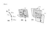
- FIG. 3illustrates the sampling planes used in generating the straightened spine volume, and is referred when describing the method of FIG. 2 .
- a viewing directionis assigned to each of the centerline points P V ⁇ [p 1 . . . p M ].
- the viewing directionsdefine a perpendicular plane used for sampling the original data at each centerline point.
- the viewing direction ⁇ right arrow over (v) ⁇ d for each pointis assigned based on the heading of the next series points; i.e., this vector can point in the direction of its next neighboring point or series of neighboring points.
- the viewing direction ⁇ right arrow over (v) ⁇ ddetermines the normal of the plane that will be sampled.
- the remaining orthogonal vectors( ⁇ right arrow over (v) ⁇ h , ⁇ right arrow over (v) ⁇ w ) determine the rotation within the plane. Since these vectors point in the same relative directions as in the original volume, the reformatted volume will have similar directions to the original volume. For example, the left side of the patient in the original volume will correspond to the same approximate direction in the reformatted volume.
- Image (a) of FIG. 3shows a centerline 302 defined by centerline points p x , p x+1 , p x+2 , and p x+3 .
- Image (b) of FIG. 3shows the viewing direction ⁇ right arrow over (v) ⁇ d determined for centerline point 304 .
- the viewing direction ⁇ right arrow over (v) ⁇ dis approximately tangent to the centerline, and the vectors ⁇ right arrow over (v) ⁇ h and ⁇ right arrow over (v) ⁇ w are orthogonal to ⁇ right arrow over (v) ⁇ d .
- a local plane surrounding each centerline pointis defined based on the viewing direction of each point.
- a local plane centered at the centerline point and orthogonal to the viewing directionis defined.
- the local plane at each pointis defined by the vectors ⁇ right arrow over (v) ⁇ h and ⁇ right arrow over (v) ⁇ w at that point.
- the height and width of the local planeare limited to mainly include the vertebra. The height and width can be hardcoded and constant based on expected dimensions of the vertebra, or can be variable based upon segmentation results for a particular patient. It is possible to increase the dimensions of the local plane to include other anatomic objects in addition to the spine.
- Image (b) of FIG. 3shows a local plane 306 defined at the centerline point 304 .
- the image volumeis sampled at each local plane to generate a series of 2D images.
- a 2D imageis generated at each local plane by sampling the original image volume about the plane.
- the image data for each point in each local planeis defined based on the image data in the original image volume.
- the 2D image corresponding to each local planecan be generated by sampling the original image volume using tri-linear interpolation or other well known sampling methods.
- Image (c) of FIG. 3shows a series of 2D images 310 , 312 , and 314 resulting from sampling in local planes.
- the series of 2D imagesare stacked together to generate a straightened volume.
- the 2D images 310 , 312 , and 314 of image (c) of FIG. 3can be stacked to for a straightened 3D image volume.
- FIG. 4illustrates exemplary reformatted CT image volumes generated using the method of FIG. 2 .
- images 402 , 404 , and 406are views of a straightened spine volume of a spine with an abnormal curvature.
- Image 402is a coronal slice of the reformatted volume
- image 404is a volume rendering of the reformatted volume from the front
- image 406is a volume rendering of the reformatted volume from the back.
- Images 408 , 410 , and 412are views of a straightened spine volume of a spine with a relatively normal curvature.
- Image 408is a coronal slice of the reformatted volume
- image 410is a volume rendering of the reformatted volume from the front
- image 412is a volume rendering of the reformatted volume from the back.
- the individual vertebraeare easy to see and analyze in straightened volumes. However, defects of the spine involving its curvatures, such as scoliosis, may be difficult to detect. Comparing image 402 (abnormal curvature) to image 408 (normal curvature), it can be seen that the straightened images mostly hide the curvature of the spine, although defects are noticeable in the upper and lower vertebrae of image 402 .
- FIG. 5illustrates a method for generating a reformatted image volume according to another embodiment of the present invention.
- the method of FIG. 5can be performed to implement step 106 of FIG. 1 , and generates an MRP based volume that aligns the spine along the natural curvature of the spine.
- This methodreformats the image volume based on a curved MPR automatically defined through the spine centerline.
- the MRP base volume generated by this methodeliminates the curvature of the spine in the posterior to anterior direction, but preserves the curvatures of the spine in the left to right directions. In this method, the viewing directions for the centerline points are not necessary, and the spine is centered within the volume in the automatic generation of the reformatted image volume.
- the average of the x-coordinates of the centerline points P V ⁇ [p 1 . . . p M ]is calculated.
- the x-coordinate and x directionrefers to the left and right or horizontal direction of a patient. This average is used to center the final volume sampling region within the center of the vertebra. Similar to the previous method, planar samples are taken from the volume and stack together. The planes are all parallel to the transverse plane and stacked upon each other relative to the offset in the x direction. Offsets in the y directions are ignored.
- a shift value from the average of the x-coordinatesis determined for each centerline point.
- the shift value for a centerline pointis a distance in the x-direction of that centerline point from the average of the x-coordinates of all of the centerline points.
- a 2D imageis sampled at each centerline point resulting in a series of 2D images.
- Each 2D imageis sampled in a local axial plane at each centerline point, i.e., in the transverse plane for all points.
- the height and width of the local planeare limited to mainly include the vertebra.
- the height and widthcan be hardcoded and constant based on expected dimensions of the vertebra, or can be variable based upon segmentation results for a particular patient. It is possible to increase the dimensions of the local plane to include other anatomic objects in addition to the spine.
- the 2D image at each centerline pointcan be generated by sampling the original image volume using tri-linear interpolation or other well known sampling methods.
- the series of 2D imagesare stacked, with each 2D image shifted in the x-direction from the average of the x-coordinates by the shift value of the corresponding centerline point. Accordingly, the 2D images are aligned in the front-back direction, but 2D each image is shifted in the right-left (x) direction based on the location of the centerline point corresponding to that image. This results in a reformatted image volume in which the curvature of the spine is preserved in the left and right directions.
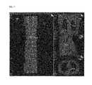
- FIG. 6illustrates exemplary reformatted CT image volumes generated using the method of FIG. 5 .
- images 602 , 604 , and 606are views of a MPR based reformatted volume of a spine with an abnormal curvature.
- Image 602is a coronal slice of the reformatted volume
- image 604is a volume rendering of the reformatted volume from the front
- image 606is a volume rendering of the reformatted volume from the back.
- Images 608 , 610 , and 612are views of a MPR based reformatted volume of a spine with a relatively normal curvature.
- Image 608is a coronal slice of the reformatted volume
- image 610is a volume rendering of the reformatted volume from the front
- image 612is a volume rendering of the reformatted volume from the back.
- curvatures of the spine in the coronal planeare visible in the MPR based reformatted image volumes. Comparing image 602 (abnormal curvature) to image 608 (normal curvature), the abnormal curvatures in image 602 can be easily seen.
- the reformatted image volumesuch as a reformatted image volume generated using the method of FIG. 2 or the method of FIG. 5 .
- the reformatted image volumecan be outputted by displaying the reformatted image volume on a display, such as a display of a computer system. As shown in FIGS. 4 and 6 , the reformatted image volume can be displayed in 2D slices of the reformatted image volume, as well as 3D volume renderings of the reformatted image volume.
- the reformatted image volumecan also be output by printing images of the reformatted image volume, storing the reformatted image volume on memory or storage of a computer system, and outputting the reformatted image volume and centerline for use in an image processing application, such as a segmentation application, a diagnostic application, or an application for interactive user analysis.
- an image processing applicationsuch as a segmentation application, a diagnostic application, or an application for interactive user analysis.
- FIG. 7illustrates displaying a reformatted image volume in a computer implemented spine analysis application.
- the application of FIG. 7allows for user interaction to analyze the spine using the reformatted image volume.
- the applicationis capable of displaying a straightened reformatted image and an MPR base reformatted image.
- the applicationdisplays coronal, sagittal, and axial slices 710 , 720 , and 730 of the original image volume.
- the applicationalso displays a coronal slice 740 of the reformatted image volume.
- the coronal slice 740is a slice of a straightened reformatted volume generated as described above in FIG. 2 .
- the reformatted volumecan displayed as slices (such as slice 740 ), a function of several slices, or 3D volume renderings.
- the applicationcan map between the reformatted image volume and the original image volume.
- a user selection point 742is shown in the coronal slice 740 of the reformatted volume, and corresponding locations 712 , 722 , and 732 are shown in the coronal, sagittal, and axial slices 710 , 720 , and 730 of the original image volume.
- This mappingallows for verification and further analysis of areas of interest. Additionally, the mapping can allow for accurate measurements to be conducted between two given points in the reformatted volume.
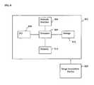
- FIG. 8A high level block diagram of such a computer is illustrated in FIG. 8 .
- Computer 802contains a processor 804 which controls the overall operation of the computer 802 by executing computer program instructions which define such operation.
- the computer program instructionsmay be stored in a storage device 812 (e.g., magnetic disk) and loaded into memory 810 when execution of the computer program instructions is desired.
- a storage device 812e.g., magnetic disk
- FIG. 7can be defined by the computer program instructions stored in the memory 810 and/or storage 812 and controlled by the processor 804 executing the computer program instructions.
- the original and reformatted image volume datacan be stored in the memory 810 and/or the storage 812 .
- An image acquisition device 820such as a CT scanning device, can be connected to the computer 802 to input scanned 3D image volumes to the computer 802 . It is possible to implement the image acquisition device 820 and the computer 802 as one device. It is also possible the image acquisition device 820 and the computer 802 communicate wirelessly through a network.
- the computer 802also includes one or more network interfaces 806 for communicating with other devices via a network.
- the computer 802also includes other input/output devices 808 that enable user interaction with the computer 802 (e.g., display, keyboard, mouse, speakers, buttons, etc.)
- input/output devices 808that enable user interaction with the computer 802 (e.g., display, keyboard, mouse, speakers, buttons, etc.)
- FIG. 8is a high level representation of some of the components of such a computer for illustrative purposes.
Landscapes
- Health & Medical Sciences (AREA)
- Engineering & Computer Science (AREA)
- Physics & Mathematics (AREA)
- Life Sciences & Earth Sciences (AREA)
- Theoretical Computer Science (AREA)
- General Physics & Mathematics (AREA)
- Computer Vision & Pattern Recognition (AREA)
- Heart & Thoracic Surgery (AREA)
- Molecular Biology (AREA)
- Pathology (AREA)
- Physical Education & Sports Medicine (AREA)
- Biomedical Technology (AREA)
- Biophysics (AREA)
- Medical Informatics (AREA)
- Oral & Maxillofacial Surgery (AREA)
- Surgery (AREA)
- Animal Behavior & Ethology (AREA)
- General Health & Medical Sciences (AREA)
- Public Health (AREA)
- Veterinary Medicine (AREA)
- Dentistry (AREA)
- Orthopedic Medicine & Surgery (AREA)
- Geometry (AREA)
- Rheumatology (AREA)
- Computer Graphics (AREA)
- Apparatus For Radiation Diagnosis (AREA)
- Magnetic Resonance Imaging Apparatus (AREA)
Abstract
Description
Claims (23)
Priority Applications (1)
| Application Number | Priority Date | Filing Date | Title |
|---|---|---|---|
| US12/150,663US8423124B2 (en) | 2007-05-18 | 2008-04-30 | Method and system for spine visualization in 3D medical images |
Applications Claiming Priority (2)
| Application Number | Priority Date | Filing Date | Title |
|---|---|---|---|
| US93872707P | 2007-05-18 | 2007-05-18 | |
| US12/150,663US8423124B2 (en) | 2007-05-18 | 2008-04-30 | Method and system for spine visualization in 3D medical images |
Publications (2)
| Publication Number | Publication Date |
|---|---|
| US20080287796A1 US20080287796A1 (en) | 2008-11-20 |
| US8423124B2true US8423124B2 (en) | 2013-04-16 |
Family
ID=40028224
Family Applications (1)
| Application Number | Title | Priority Date | Filing Date |
|---|---|---|---|
| US12/150,663Expired - Fee RelatedUS8423124B2 (en) | 2007-05-18 | 2008-04-30 | Method and system for spine visualization in 3D medical images |
Country Status (1)
| Country | Link |
|---|---|
| US (1) | US8423124B2 (en) |
Cited By (6)
| Publication number | Priority date | Publication date | Assignee | Title |
|---|---|---|---|---|
| KR20170060701A (en)* | 2015-11-25 | 2017-06-02 | 한신대학교 산학협력단 | Estimation method of spine position from 3-dimensional human body image |
| US10032296B2 (en) | 2013-10-30 | 2018-07-24 | Koninklijke Philips N.V. | Volumertric image data visualization |
| US10390726B2 (en)* | 2016-03-28 | 2019-08-27 | Siemens Healthcare Gmbh | System and method for next-generation MRI spine evaluation |
| WO2020133236A1 (en)* | 2018-12-28 | 2020-07-02 | 深圳迈瑞生物医疗电子股份有限公司 | Spinal imaging method and ultrasonic imaging system |
| US20220008028A1 (en)* | 2017-12-21 | 2022-01-13 | Shanghai United Imaging Healthcare Co., Ltd. | System and method for medical imaging of intervertebral discs |
| US11350995B2 (en) | 2016-10-05 | 2022-06-07 | Nuvasive, Inc. | Surgical navigation systems and methods |
Families Citing this family (22)
| Publication number | Priority date | Publication date | Assignee | Title |
|---|---|---|---|---|
| DE102010001020A1 (en)* | 2010-01-19 | 2011-07-21 | Medizinische Fakultät Otto-von-Guericke-Universität Magdeburg, 39120 | Device for determining vertebral spacing of the spine |
| US8676298B2 (en)* | 2010-08-30 | 2014-03-18 | Fujifilm Corporation | Medical image alignment apparatus, method, and program |
| US9218657B2 (en) | 2012-06-12 | 2015-12-22 | Country View Medical Center | Method of obtaining and analyzing data from an upright MRI from the spinal region of a subject |
| WO2015039054A1 (en)* | 2013-09-13 | 2015-03-19 | The Regents Of The University Of California | Method and system for analysis of volumetric data |
| WO2015191641A1 (en) | 2014-06-10 | 2015-12-17 | Smart Hybrid Systems Incorporated | High energy density capacitor with micrometer structures and nanometer components |
| US10460508B2 (en)* | 2014-06-12 | 2019-10-29 | Siemens Healthcare Gmbh | Visualization with anatomical intelligence |
| US9558568B2 (en) | 2014-06-27 | 2017-01-31 | Siemens Healthcare Gmbh | Visualization method for a human skeleton from a medical scan |
| US10524723B2 (en)* | 2014-07-23 | 2020-01-07 | Alphatec Spine, Inc. | Method for measuring the displacements of a vertebral column |
| US9645212B2 (en) | 2014-10-21 | 2017-05-09 | The Regents Of The University Of California | Fiber tractography using entropy spectrum pathways |
| US10909414B2 (en) | 2015-04-30 | 2021-02-02 | The Regents Of The University Of California | Entropy field decomposition for image analysis |
| US10312026B2 (en) | 2015-06-09 | 2019-06-04 | Smart Hybird Systems Incorporated | High energy density capacitor with high aspect micrometer structures and a giant colossal dielectric material |
| EP3376987B1 (en)* | 2015-11-19 | 2020-10-28 | EOS Imaging | Method of preoperative planning to correct spine misalignment of a patient |
| WO2017132403A1 (en) | 2016-01-26 | 2017-08-03 | The Regents Of The University Of California | Symplectomorphic image registration |
| EP3220357A3 (en)* | 2016-03-15 | 2018-01-10 | Siemens Healthcare GmbH | Model-based generation and display of three-dimensional objects |
| US11432736B2 (en) | 2016-12-08 | 2022-09-06 | Koninklijke Philips N.V. | Simplified navigation of spinal medical imaging data |
| US11270445B2 (en) | 2017-03-06 | 2022-03-08 | The Regents Of The University Of California | Joint estimation with space-time entropy regularization |
| CN108320314B (en)* | 2017-12-29 | 2021-07-09 | 北京优视魔方科技有限公司 | Image processing method and device based on CT transverse image and display system |
| KR102044528B1 (en) | 2018-03-15 | 2019-11-14 | 울산대학교 산학협력단 | Apparatus and method for modeling bone |
| US11131737B2 (en) | 2019-06-04 | 2021-09-28 | The Regents Of The University Of California | Joint estimation diffusion imaging (JEDI) |
| CN111260703B (en)* | 2020-01-08 | 2023-04-11 | 浙江大学 | Method, system, medium and storage medium for obtaining spinal straightening image set |
| EP4125610B1 (en) | 2020-04-03 | 2023-08-02 | Koninklijke Philips N.V. | Computer-implemented method for visualization of an elongated anatomical structure |
| CN115346022A (en)* | 2022-08-17 | 2022-11-15 | 联影智能医疗科技(北京)有限公司 | Curved surface reconstruction method, computer device and storage medium |
Citations (14)
| Publication number | Priority date | Publication date | Assignee | Title |
|---|---|---|---|---|
| US6023495A (en) | 1998-05-15 | 2000-02-08 | International Business Machines Corporation | System and method for acquiring three-dimensional data subject to practical constraints by integrating CT slice data and CT scout images |
| US6028907A (en) | 1998-05-15 | 2000-02-22 | International Business Machines Corporation | System and method for three-dimensional geometric modeling by extracting and merging two-dimensional contours from CT slice data and CT scout data |
| US6608916B1 (en) | 2000-08-14 | 2003-08-19 | Siemens Corporate Research, Inc. | Automatic detection of spine axis and spine boundary in digital radiography |
| US20050018885A1 (en) | 2001-05-31 | 2005-01-27 | Xuesong Chen | System and method of anatomical modeling |
| US6850635B2 (en) | 2000-09-29 | 2005-02-01 | Koninklijke Philips Electronics, N.V. | Method and system for extracting spine frontal geometrical data including vertebra pedicle locations |
| US20050117787A1 (en)* | 2001-12-27 | 2005-06-02 | The Govenment Of The United States Of America As Represented By The Seceretary Of The Department | Automated centerline detection algorithm for colon-like 3d surfaces |
| US6978039B2 (en)* | 2001-12-13 | 2005-12-20 | General Electric Company | Method and system for segmentation of medical images |
| US20060110017A1 (en)* | 2004-11-25 | 2006-05-25 | Chung Yuan Christian University | Method for spinal disease diagnosis based on image analysis of unaligned transversal slices |
| US20060173271A1 (en)* | 2005-02-01 | 2006-08-03 | Hong Shen | Method for analyzing medical image data |
| US7095881B2 (en)* | 2000-01-14 | 2006-08-22 | Koninklijke Philips Electronics N.V. | Processing method and system for 3-D geometric modeling of the spine |
| US20070055178A1 (en) | 2005-09-07 | 2007-03-08 | Jeanne Verre | Systems and methods for computer aided detection of spinal curvature using images and angle measurements |
| US20070092121A1 (en) | 2005-09-15 | 2007-04-26 | Senthil Periaswamy | System and method for automatic extraction of spinal cord from 3D volumetric images |
| US20070121778A1 (en) | 2005-10-17 | 2007-05-31 | Siemens Corporate Research Inc | Method and System For Spinal Cord Detection In Computed Tomography Volume Data |
| US20070127799A1 (en) | 2005-10-17 | 2007-06-07 | Siemens Corporate Research Inc | Method and system for vertebrae and intervertebral disc localization in magnetic resonance images |
- 2008
- 2008-04-30USUS12/150,663patent/US8423124B2/ennot_activeExpired - Fee Related
Patent Citations (14)
| Publication number | Priority date | Publication date | Assignee | Title |
|---|---|---|---|---|
| US6028907A (en) | 1998-05-15 | 2000-02-22 | International Business Machines Corporation | System and method for three-dimensional geometric modeling by extracting and merging two-dimensional contours from CT slice data and CT scout data |
| US6023495A (en) | 1998-05-15 | 2000-02-08 | International Business Machines Corporation | System and method for acquiring three-dimensional data subject to practical constraints by integrating CT slice data and CT scout images |
| US7095881B2 (en)* | 2000-01-14 | 2006-08-22 | Koninklijke Philips Electronics N.V. | Processing method and system for 3-D geometric modeling of the spine |
| US6608916B1 (en) | 2000-08-14 | 2003-08-19 | Siemens Corporate Research, Inc. | Automatic detection of spine axis and spine boundary in digital radiography |
| US6850635B2 (en) | 2000-09-29 | 2005-02-01 | Koninklijke Philips Electronics, N.V. | Method and system for extracting spine frontal geometrical data including vertebra pedicle locations |
| US20050018885A1 (en) | 2001-05-31 | 2005-01-27 | Xuesong Chen | System and method of anatomical modeling |
| US6978039B2 (en)* | 2001-12-13 | 2005-12-20 | General Electric Company | Method and system for segmentation of medical images |
| US20050117787A1 (en)* | 2001-12-27 | 2005-06-02 | The Govenment Of The United States Of America As Represented By The Seceretary Of The Department | Automated centerline detection algorithm for colon-like 3d surfaces |
| US20060110017A1 (en)* | 2004-11-25 | 2006-05-25 | Chung Yuan Christian University | Method for spinal disease diagnosis based on image analysis of unaligned transversal slices |
| US20060173271A1 (en)* | 2005-02-01 | 2006-08-03 | Hong Shen | Method for analyzing medical image data |
| US20070055178A1 (en) | 2005-09-07 | 2007-03-08 | Jeanne Verre | Systems and methods for computer aided detection of spinal curvature using images and angle measurements |
| US20070092121A1 (en) | 2005-09-15 | 2007-04-26 | Senthil Periaswamy | System and method for automatic extraction of spinal cord from 3D volumetric images |
| US20070121778A1 (en) | 2005-10-17 | 2007-05-31 | Siemens Corporate Research Inc | Method and System For Spinal Cord Detection In Computed Tomography Volume Data |
| US20070127799A1 (en) | 2005-10-17 | 2007-06-07 | Siemens Corporate Research Inc | Method and system for vertebrae and intervertebral disc localization in magnetic resonance images |
Non-Patent Citations (8)
| Title |
|---|
| Archip et al., A Knowledge-Based Approach to Automatic Detection of the Spinal Cord in CT Images, 2002, IEEE Transactions on Medical Imaging, vol. 21, No. 12, pp. 1504-1516.* |
| Bitter et al., Comparison of Four Freely Available Frameworks for Image Processing and Visualization That Use ITK, published online Jan. 10, 2007, IEEE Transactions on Visualization and Computer Graphics, vol. 13, No. 3, pp. 483-493.* |
| Enders et al., Visualization of White Matter Tracts with Wrapped Streamlines, 2005, IEEE Visualization 2005, Oct. 23-28, Minneapolis, MN, USA, p. 51-58.* |
| Kanitsar et al., CPR-Curved Planar Reformation, 2002, IEEE Visualization, Oct. 27-Nov. 1, 2002, Boston, MA, USA, p. 37-44.* |
| Lell et al., New Techniques in CT Angiography, 2006, Clinical Applications of Vascular Imaging, RSNA, V 26, S45-S62.* |
| Vrotvec et al. (Automated curved planar reformation of 3D spine images, 2005, Phys. Med. Biol. 50, 4527-4540.* |
| Vrtovec, T., et al., "Curved Planar Reformation of CT Spine Data", SPIE Medical Imaging, p. 1446-1456, 2005. Proc. of SPIE, vol. 5747. |
| Yao et al., Automated Spinal Column Extraction and Partitioning, 2006, ISBI, p. 390-393.* |
Cited By (10)
| Publication number | Priority date | Publication date | Assignee | Title |
|---|---|---|---|---|
| US10032296B2 (en) | 2013-10-30 | 2018-07-24 | Koninklijke Philips N.V. | Volumertric image data visualization |
| KR20170060701A (en)* | 2015-11-25 | 2017-06-02 | 한신대학교 산학협력단 | Estimation method of spine position from 3-dimensional human body image |
| KR101908767B1 (en) | 2015-11-25 | 2018-10-16 | 한신대학교 산학협력단 | Estimation method of spine position from 3-dimensional human body image |
| US10390726B2 (en)* | 2016-03-28 | 2019-08-27 | Siemens Healthcare Gmbh | System and method for next-generation MRI spine evaluation |
| US11229377B2 (en) | 2016-03-28 | 2022-01-25 | Siemens Healthcare Gmbh | System and method for next-generation MRI spine evaluation |
| US11350995B2 (en) | 2016-10-05 | 2022-06-07 | Nuvasive, Inc. | Surgical navigation systems and methods |
| US20220008028A1 (en)* | 2017-12-21 | 2022-01-13 | Shanghai United Imaging Healthcare Co., Ltd. | System and method for medical imaging of intervertebral discs |
| US11826191B2 (en)* | 2017-12-21 | 2023-11-28 | Shanghai United Imaging Healthcare Co., Ltd. | System and method for medical imaging of intervertebral discs |
| WO2020133236A1 (en)* | 2018-12-28 | 2020-07-02 | 深圳迈瑞生物医疗电子股份有限公司 | Spinal imaging method and ultrasonic imaging system |
| CN112654301A (en)* | 2018-12-28 | 2021-04-13 | 深圳迈瑞生物医疗电子股份有限公司 | Imaging method of spine and ultrasonic imaging system |
Also Published As
| Publication number | Publication date |
|---|---|
| US20080287796A1 (en) | 2008-11-20 |
Similar Documents
| Publication | Publication Date | Title |
|---|---|---|
| US8423124B2 (en) | Method and system for spine visualization in 3D medical images | |
| EP2572332B1 (en) | Visualization of medical image data with localized enhancement | |
| JP6877868B2 (en) | Image processing equipment, image processing method and image processing program | |
| US9035941B2 (en) | Image processing apparatus and image processing method | |
| US20140307936A1 (en) | Method and apparatus for the assessment of medical images | |
| CN115830016B (en) | Medical image registration model training method and equipment | |
| US9019272B2 (en) | Curved planar reformation | |
| US7492968B2 (en) | System and method for segmenting a structure of interest using an interpolation of a separating surface in an area of attachment to a structure having similar properties | |
| JP5194138B2 (en) | Image diagnosis support apparatus, operation method thereof, and image diagnosis support program | |
| US7339586B2 (en) | Method and system for mesh-to-image registration using raycasting | |
| US12277718B2 (en) | Computer-implemented method for visualization of an elongated anatomical structure | |
| JP5295562B2 (en) | Flexible 3D rotational angiography-computed tomography fusion method | |
| US7684602B2 (en) | Method and system for local visualization for tubular structures | |
| US9767550B2 (en) | Method and device for analysing a region of interest in an object using x-rays | |
| Turlington et al. | New techniques for efficient sliding thin-slab volume visualization | |
| JP2005525863A (en) | Medical inspection system and image processing for integrated visualization of medical data | |
| US8165375B2 (en) | Method and system for registering CT data sets | |
| JP2006178772A (en) | Image processing method, system, and program | |
| Hong et al. | Intensity-based registration and combined visualization of multimodal brain images for noninvasive epilepsy surgery planning | |
| US11653853B2 (en) | Visualization of distances to walls of anatomical cavities | |
| Turlington et al. | Improved techniques for fast sliding thin-slab volume visualization | |
| Vrtovec et al. | Curved planar reformation of CT spine data | |
| Zhang et al. | Curvature-vector pair and its application in displaying CT colon data | |
| Mohd et al. | BOUNDARY DETECTION OF KIDNEY ULTRASOUND IMAGE BASED ON VECTOR GRAPHIC APPROACH |
Legal Events
| Date | Code | Title | Description |
|---|---|---|---|
| AS | Assignment | Owner name:SIEMENS CORPORATE RESEARCH, INC., NEW JERSEY Free format text:ASSIGNMENT OF ASSIGNORS INTEREST;ASSIGNORS:KIRALY, ATILLA PETER;ALVINO, CHRISTOPHER V;SHEN, HONG;REEL/FRAME:021224/0516 Effective date:20080602 | |
| AS | Assignment | Owner name:SIEMENS AKTIENGESELLSCHAFT, GERMANY Free format text:ASSIGNMENT OF ASSIGNORS INTEREST;ASSIGNOR:SIEMENS CORPORATE RESEARCH, INC.;REEL/FRAME:022506/0596 Effective date:20090403 Owner name:SIEMENS AKTIENGESELLSCHAFT,GERMANY Free format text:ASSIGNMENT OF ASSIGNORS INTEREST;ASSIGNOR:SIEMENS CORPORATE RESEARCH, INC.;REEL/FRAME:022506/0596 Effective date:20090403 | |
| STCF | Information on status: patent grant | Free format text:PATENTED CASE | |
| AS | Assignment | Owner name:SIEMENS HEALTHCARE GMBH, GERMANY Free format text:ASSIGNMENT OF ASSIGNORS INTEREST;ASSIGNOR:SIEMENS AKTIENGESELLSCHAFT;REEL/FRAME:039271/0561 Effective date:20160610 | |
| FPAY | Fee payment | Year of fee payment:4 | |
| MAFP | Maintenance fee payment | Free format text:PAYMENT OF MAINTENANCE FEE, 8TH YEAR, LARGE ENTITY (ORIGINAL EVENT CODE: M1552); ENTITY STATUS OF PATENT OWNER: LARGE ENTITY Year of fee payment:8 | |
| AS | Assignment | Owner name:SIEMENS HEALTHINEERS AG, GERMANY Free format text:ASSIGNMENT OF ASSIGNORS INTEREST;ASSIGNOR:SIEMENS HEALTHCARE GMBH;REEL/FRAME:066088/0256 Effective date:20231219 | |
| AS | Assignment | Owner name:SIEMENS HEALTHINEERS AG, GERMANY Free format text:CORRECTIVE ASSIGNMENT TO CORRECT THE ASSIGNEE PREVIOUSLY RECORDED AT REEL: 066088 FRAME: 0256. ASSIGNOR(S) HEREBY CONFIRMS THE ASSIGNMENT;ASSIGNOR:SIEMENS HEALTHCARE GMBH;REEL/FRAME:071178/0246 Effective date:20231219 | |
| FEPP | Fee payment procedure | Free format text:MAINTENANCE FEE REMINDER MAILED (ORIGINAL EVENT CODE: REM.); ENTITY STATUS OF PATENT OWNER: LARGE ENTITY | |
| LAPS | Lapse for failure to pay maintenance fees | Free format text:PATENT EXPIRED FOR FAILURE TO PAY MAINTENANCE FEES (ORIGINAL EVENT CODE: EXP.); ENTITY STATUS OF PATENT OWNER: LARGE ENTITY | |
| STCH | Information on status: patent discontinuation | Free format text:PATENT EXPIRED DUE TO NONPAYMENT OF MAINTENANCE FEES UNDER 37 CFR 1.362 | |
| FP | Lapsed due to failure to pay maintenance fee | Effective date:20250416 |