US8422847B2 - Rapid universal rack mount enclosure - Google Patents
Rapid universal rack mount enclosureDownload PDFInfo
- Publication number
- US8422847B2 US8422847B2US12/840,834US84083410AUS8422847B2US 8422847 B2US8422847 B2US 8422847B2US 84083410 AUS84083410 AUS 84083410AUS 8422847 B2US8422847 B2US 8422847B2
- Authority
- US
- United States
- Prior art keywords
- cable
- enclosure
- spool
- fiber optic
- adapters
- Prior art date
- Legal status (The legal status is an assumption and is not a legal conclusion. Google has not performed a legal analysis and makes no representation as to the accuracy of the status listed.)
- Active, expires
Links
Images


Classifications
- G—PHYSICS
- G02—OPTICS
- G02B—OPTICAL ELEMENTS, SYSTEMS OR APPARATUS
- G02B6/00—Light guides; Structural details of arrangements comprising light guides and other optical elements, e.g. couplings
- G02B6/44—Mechanical structures for providing tensile strength and external protection for fibres, e.g. optical transmission cables
- G02B6/4439—Auxiliary devices
- G02B6/444—Systems or boxes with surplus lengths
- G02B6/4453—Cassettes
- G—PHYSICS
- G02—OPTICS
- G02B—OPTICAL ELEMENTS, SYSTEMS OR APPARATUS
- G02B6/00—Light guides; Structural details of arrangements comprising light guides and other optical elements, e.g. couplings
- G02B6/44—Mechanical structures for providing tensile strength and external protection for fibres, e.g. optical transmission cables
- G02B6/4439—Auxiliary devices
- G02B6/444—Systems or boxes with surplus lengths
- G02B6/4441—Boxes
- G02B6/4446—Cable boxes, e.g. splicing boxes with two or more multi fibre cables
- G—PHYSICS
- G02—OPTICS
- G02B—OPTICAL ELEMENTS, SYSTEMS OR APPARATUS
- G02B6/00—Light guides; Structural details of arrangements comprising light guides and other optical elements, e.g. couplings
- G02B6/24—Coupling light guides
- G02B6/36—Mechanical coupling means
- G02B6/3616—Holders, macro size fixtures for mechanically holding or positioning fibres, e.g. on an optical bench
- G—PHYSICS
- G02—OPTICS
- G02B—OPTICAL ELEMENTS, SYSTEMS OR APPARATUS
- G02B6/00—Light guides; Structural details of arrangements comprising light guides and other optical elements, e.g. couplings
- G02B6/24—Coupling light guides
- G02B6/36—Mechanical coupling means
- G02B6/38—Mechanical coupling means having fibre to fibre mating means
- G02B6/3807—Dismountable connectors, i.e. comprising plugs
- G02B6/381—Dismountable connectors, i.e. comprising plugs of the ferrule type, e.g. fibre ends embedded in ferrules, connecting a pair of fibres
- G02B6/3825—Dismountable connectors, i.e. comprising plugs of the ferrule type, e.g. fibre ends embedded in ferrules, connecting a pair of fibres with an intermediate part, e.g. adapter, receptacle, linking two plugs
- G—PHYSICS
- G02—OPTICS
- G02B—OPTICAL ELEMENTS, SYSTEMS OR APPARATUS
- G02B6/00—Light guides; Structural details of arrangements comprising light guides and other optical elements, e.g. couplings
- G02B6/24—Coupling light guides
- G02B6/36—Mechanical coupling means
- G02B6/38—Mechanical coupling means having fibre to fibre mating means
- G02B6/3807—Dismountable connectors, i.e. comprising plugs
- G02B6/3873—Connectors using guide surfaces for aligning ferrule ends, e.g. tubes, sleeves, V-grooves, rods, pins, balls
- G02B6/3885—Multicore or multichannel optical connectors, i.e. one single ferrule containing more than one fibre, e.g. ribbon type
- G—PHYSICS
- G02—OPTICS
- G02B—OPTICAL ELEMENTS, SYSTEMS OR APPARATUS
- G02B6/00—Light guides; Structural details of arrangements comprising light guides and other optical elements, e.g. couplings
- G02B6/44—Mechanical structures for providing tensile strength and external protection for fibres, e.g. optical transmission cables
- G02B6/4439—Auxiliary devices
- G02B6/444—Systems or boxes with surplus lengths
- G02B6/4452—Distribution frames
- G02B6/44524—Distribution frames with frame parts or auxiliary devices mounted on the frame and collectively not covering a whole width of the frame or rack
- G—PHYSICS
- G02—OPTICS
- G02B—OPTICAL ELEMENTS, SYSTEMS OR APPARATUS
- G02B6/00—Light guides; Structural details of arrangements comprising light guides and other optical elements, e.g. couplings
- G02B6/44—Mechanical structures for providing tensile strength and external protection for fibres, e.g. optical transmission cables
- G02B6/4439—Auxiliary devices
- G02B6/444—Systems or boxes with surplus lengths
- G02B6/44528—Patch-cords; Connector arrangements in the system or in the box
- G—PHYSICS
- G02—OPTICS
- G02B—OPTICAL ELEMENTS, SYSTEMS OR APPARATUS
- G02B6/00—Light guides; Structural details of arrangements comprising light guides and other optical elements, e.g. couplings
- G02B6/44—Mechanical structures for providing tensile strength and external protection for fibres, e.g. optical transmission cables
- G02B6/4439—Auxiliary devices
- G02B6/444—Systems or boxes with surplus lengths
- G02B6/4453—Cassettes
- G02B6/4454—Cassettes with splices
- G—PHYSICS
- G02—OPTICS
- G02B—OPTICAL ELEMENTS, SYSTEMS OR APPARATUS
- G02B6/00—Light guides; Structural details of arrangements comprising light guides and other optical elements, e.g. couplings
- G02B6/44—Mechanical structures for providing tensile strength and external protection for fibres, e.g. optical transmission cables
- G02B6/4439—Auxiliary devices
- G02B6/4457—Bobbins; Reels
- G—PHYSICS
- G02—OPTICS
- G02B—OPTICAL ELEMENTS, SYSTEMS OR APPARATUS
- G02B6/00—Light guides; Structural details of arrangements comprising light guides and other optical elements, e.g. couplings
- G02B6/44—Mechanical structures for providing tensile strength and external protection for fibres, e.g. optical transmission cables
- G02B6/4439—Auxiliary devices
- G02B6/4471—Terminating devices ; Cable clamps
- G02B6/44765—Terminating devices ; Cable clamps with means for strain-relieving to exterior cable layers
- G—PHYSICS
- G02—OPTICS
- G02B—OPTICAL ELEMENTS, SYSTEMS OR APPARATUS
- G02B6/00—Light guides; Structural details of arrangements comprising light guides and other optical elements, e.g. couplings
- G02B6/44—Mechanical structures for providing tensile strength and external protection for fibres, e.g. optical transmission cables
- G02B6/4439—Auxiliary devices
- G02B6/4471—Terminating devices ; Cable clamps
- G02B6/4478—Bending relief means
- G—PHYSICS
- G02—OPTICS
- G02B—OPTICAL ELEMENTS, SYSTEMS OR APPARATUS
- G02B6/00—Light guides; Structural details of arrangements comprising light guides and other optical elements, e.g. couplings
- G02B6/46—Processes or apparatus adapted for installing or repairing optical fibres or optical cables
- G02B6/50—Underground or underwater installation; Installation through tubing, conduits or ducts
Definitions
- Fiber distribution framesare adapted to aid in the connection of fiber optic equipment.
- fiber optic cableis routed between the fiber optic equipment and/or the fiber distribution frames.
- the length of fiber optic cable needed between the fiber optic equipment and/or the fiber distribution framesvaries depending on the location of the equipment in the fiber distribution frame or the location of the fiber distribution frames. As a result, there is a need for a system to effectively manage varying lengths of fiber optic cable.
- the cable enclosure assemblyincludes an enclosure, a cable spool and a length of fiber optic cable.
- the enclosuredefines an interior region, a first opening and a second opening aligned with the first opening. The first and second openings provide access to the interior region.
- the cable spoolis disposed in the interior region of the enclosure and is rotatably engaged with the enclosure.
- the cable spoolincludes a drum and a flange engaged to the drum.
- the flangehas an outer peripheral side, a cable management portion and an adapter bulkhead portion.
- the adapter bulkhead portionextends outwardly from the cable management portion and forms a portion of the outer peripheral side.
- the length of the fiber optic cableis dispose about the drum of the cable spool.
- the cable enclosure assemblyincludes an enclosure, a cable spool, a plurality of adapters and a length of fiber optic cable.
- the enclosuredefines an interior region and a first opening. The first opening provides access to the interior region.
- the cable spoolis disposed in the interior region of the enclosure and rotatably engaged with the enclosure.
- the cable spoolincludes a drum and a flange engaged to the drum.
- the flangeincludes an adapter bulkhead portion.
- the plurality of adaptersis disposed on the adapter bulkhead portion. Each of the adapters including a first side and a second side.
- the length of fiber optic cableis disposed about the drum of the cable spool.
- the fiber optic cableincludes a first end and an oppositely disposed second end.
- the first endhas connectors engaged to the second sides of the adapters.
- the cable spoolis rotatable in the enclosure to a first stored position in which the first sides of the adapters are aligned with the first opening and accessible through the first opening.
- the cable enclosure assemblyincludes an enclosure, a cable spool, a plurality of adapters, a length of fiber optic cable, a first plurality of bend radius protectors and a spool lock.
- the enclosuredefines an interior region and a first opening that provides access to the interior region.
- the cable spoolis disposed in the interior region of the enclosure and rotatably engaged with the enclosure.
- the cable spoolincludes a drum and a flange engaged to the drum.
- the flangeincludes an adapter bulkhead portion.
- the plurality of adaptersis disposed on the adapter bulkhead portion. Each of the adapters including a first side and a second side.
- the length of fiber optic cableis disposed about the drum of the cable spool.
- the fiber optic cableincludes a first end and an oppositely disposed second end.
- the first endhas connectors engaged to the second sides of the adapters.
- the first plurality of bend radius protectorsis disposed adjacent to the first opening.
- the spool lockis adapted for engagement with the cable spool to prevent rotation of the cable spool relative to the enclosure.
- the spool lockis adapted to engage the cable spool when the cable spool is in a first stored position in which the first sides of the adapters are aligned with the first opening and accessible through the first opening.
- Another aspect of the present disclosurerelates to cable routing configurations that incorporate rotating spool technology.
- the fiber optic network assemblyincludes a first optical distribution frame having a cable enclosure assembly.
- the cable enclosure assemblyincludes an enclosure mounted to the first optical distribution frame.
- a cable spoolis rotatably disposed in the enclosure.
- a length of fiber optic cableis wrapped around the cable spool.
- the fiber optic cablehas a first end and an oppositely disposed second end.
- the second endincludes a multi-fiber connector.
- a second optical distribution frameincludes an adapted that is remotely disposed from the first optical distribution frame. The second end of the fiber optic cable of the cable enclosure assembly of the first optical distribution frame is engaged to the adapter of the second optical distribution frame.
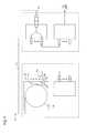
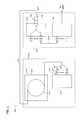
- FIG. 1is a schematic representation of a fiber optic network assembly having exemplary features of aspects in accordance with the principles of the present disclosure.
- FIG. 2is a rear perspective view of a multi-fiber connector suitable for use in the fiber optic network assembly of FIG. 1 .
- FIG. 3is a front perspective view of the multi-fiber connector of FIG. 2 .
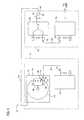
- FIG. 4is an alternate embodiment of the fiber optic network assembly of FIG. 1 .
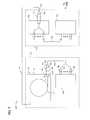
- FIG. 5is an alternate embodiment of the fiber optic network assembly of FIG. 1 .
- FIG. 6is an alternate embodiment of the fiber optic network assembly of FIG. 1 .
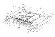
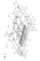
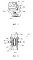
- FIG. 7is a front perspective view of a cable enclosure assembly suitable for use in the fiber optic network assembly of FIG. 1 .
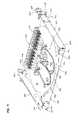
- FIG. 8is a rear perspective view of the cable enclosure assembly of FIG. 7 .
- FIG. 9is a top view of the cable enclosure assembly of FIG. 7 .
- FIG. 10is a cross-sectional view of the cable enclosure assembly of FIG. 7 .
- FIG. 11is a perspective view of an adapter suitable for use with the cable enclosure assembly of FIG. 7 .
- FIG. 12is a cross-sectional view of the adapter of FIG. 11 .
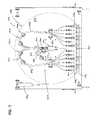
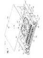
- FIG. 13is a perspective view of an alternate embodiment of a cable enclosure assembly showing a cable spool in a first stored position.
- FIG. 14is a perspective view of the cable enclosure assembly of FIG. 13 .
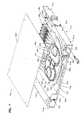
- FIG. 15is an exploded perspective view of the cable enclosure assembly of FIG. 13 showing a spool lock.
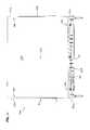
- FIG. 16is a top view of the cable enclosure assembly of FIG. 13 .
- FIG. 17is a front view of the cable enclosure assembly of FIG. 13 .
- FIG. 18is a side view of the cable enclosure assembly of FIG. 13 .
- FIG. 19is perspective view of the cable enclosure assembly with a cover removed showing the cable spool in a second stored position.
- the fiber optic network assembly 10includes a first optical distribution frame 12 and a second optical distribution frame 14 .
- the first optical distribution frame 12includes a cable enclosure assembly, generally designated 20 .
- the cable enclosure assembly 20includes an enclosure 22 and a cable spool 24 rotatably disposed in the enclosure 22 .
- a length of fiber optic cable 26is wrapped around the cable spool 24 .
- the length of fiber optic cable 26 wrapped around the cable spool 24is greater than or equal to about 80 feet.
- the length of fiber optic cable 26 wrapped around the cable spool 24is greater than or equal to about 100 feet.
- the fiber optic cable 26has an outer diameter that is 3 millimeter.
- the fiber optic cable 26is a multi-fiber cable. In one aspect of the present disclosure, the fiber optic cable 26 includes at least 6 fibers. In another aspect of the present disclosure, the fiber optic cable 26 includes at least 12 fibers.
- the fiber optic cable 26includes a first end 28 and an oppositely disposed second end 30 .
- the first end 28 and second ends 30are connectorized.
- the first end 28includes a plurality of single fiber connectors 32 (e.g., SC connectors, LC connectors, LX.5 connectors, ST connectors, FC connectors, MU connectors, etc.).
- the plurality of single fiber connectors 32is adapted for engagement with a first side 34 of a plurality of fiber optic adapters 36 .
- the plurality of adapters 36is disposed on the cable spool 24 so that the plurality of adapters 36 rotates in unison with the cable spool 24 when the fiber optic cable 26 is dispensed from the cable spool 24 .
- the second end 30 of the fiber optic cable 26includes a multi-fiber connector 38 (e.g., MT connector, Multi-fiber Push-On (MPO) connector, etc.).
- a multi-fiber connector 38e.g., MT connector, Multi-fiber Push-On (MPO) connector, etc.
- An exemplary multi-fiber connector suitable for use with the fiber optic cable 26is disclosed in U.S. Pat. No. 5,214,730, the disclosure of which is hereby incorporated by reference in its entirety.
- Exemplary multi-fiber connectors suitable for use with the fiber optic cable 26are available from US Conec Ltd. of Hickory, N.C., USA as part numbers C10821, C10822, C8190, and C10823. Fiber optic connectors related to part numbers C10821, C10822, C8190, and C10823 are known as MTP® connectors.
- a suitable multi-fiber connectorhas been described in U.S. Patent Application Publication No. 2009/0324181, the disclosure of which is hereby
- the multi-fiber connector 38is adapted for engagement with an adapter 40 .
- the adapter 40is adapted to mechanical couple the multi-fiber connector 38 to a second multi-fiber connector.
- the adapter 40is remotely disposed from the fiber optic cable enclosure assembly 20 . In the depicted embodiment of FIG. 1 , the adapter 40 is disposed on a first panel assembly 42 of the second optical distribution frame 14 .
- the second end 30 of the fiber optic cable 26is paid out from the cable spool 24 by pulling on the second end 30 of the fiber optic cable 26 .
- the cable spool 24rotates relative to the enclosure 22 . Since the plurality of adapters 36 is disposed on the cable spool 24 , the first end 28 of the fiber optic cable 26 can remain connected to the plurality of adapters 36 without damaging the fiber optic cable 26 .
- FIG. 4an alternate embodiment of a cable enclosure assembly 20 ′ is shown in which the plurality of adapters 36 is disposed on the enclosure 22 so that the plurality of adapters 36 is remote from the cable spool 24 .
- the first end 28 of the fiber optic cable 26is disconnected from the first side 34 of the adapters 36 so that the second end 30 of the fiber optic cable 26 can be paid out without damaging the fiber optic cable 26 .
- the first end 28 of the fiber optic cable 26is stored on the cable spool 24 while the second end 30 of the fiber optic cable 26 is paid out.
- the first end 28 of the fiber optic cable 26is stored on a flange of the cable spool 24 while the second end 30 is paid out.
- the first end 28 of the fiber optic cable 26is engaged to the plurality of adapters 36 after a desired length of the fiber optic cable 26 has been paid out from the cable spool 24 .
- a cross-connect cable 44optically connects the first panel assembly 42 of the second optical distribution frame 14 to a second panel assembly 46 of the second optical distribution frame 14 .
- the cross-connect cable 44is engaged to one of a first plurality of adapters 48 on the first panel assembly 42 and one of a second plurality of adapters 50 on the second panel assembly 46 of the second optical distribution frame 14 .
- a jumper cable 52optically connects the fiber optic enclosure assembly 20 of the first optical distribution frame 12 to an active component 54 of the first optical distribution frame 12 .
- a first connectorized end 56 of a jumper cable 52is engaged to a second side 58 of one of the plurality of adapters 36 of the fiber optic cable enclosure assembly 20 while a second connectorized end 60 of the jumper cable 52 is optically engaged to the active component 54 .
- the jumper cable 52has a length that is greater than or equal to 2 feet. In another aspect of the present disclosure, the length of the jumper cable 52 is greater than or equal to 5 feet. In another aspect of the present disclosure, the length of the jumper cable 52 is greater than or equal to 10 feet.
- the first optical fiber optic network assembly 100includes a first optical distribution frame 102 and a second optical distribution frame 104 .
- the first optical distribution frame 102includes a cable enclosure assembly, generally designated 110 .
- the cable enclosure assembly 110includes an enclosure 112 and a cable spool 114 rotatably disposed in the enclosure 112 .
- a length of multi-fiber fiber optic cable 116is wrapped around the cable spool 114 .
- the fiber optic cable 116includes a first end 118 and an oppositely disposed second end 120 .
- the first end 118 and second ends 120are connectorized.
- the first end 118includes a first multi-fiber connector 122 (e.g., MT connector, Multi-fiber Push-On (MPO) connector, etc.).
- the first multi-fiber connector 122is adapted for engagement with a first side 124 of a multi-fiber adapter 126 disposed on the enclosure 112 of the cable enclosure assembly 110 so that the multi-fiber adapter 126 is remote from the cable spool 114 .
- the second end 120 of the fiber optic cable 116includes a second multi-fiber connector 128 (e.g., MT connector, Multi-fiber Push-On (MPO) connector, etc.).
- the second multi-fiber connector 128is adapted for engagement with an adapter 130 that is remotely disposed from the cable enclosure assembly 110 .
- the adapter 130is disposed on a first panel assembly 132 of the second optical distribution frame 104 .
- the second end 120 of the fiber optic cable 116is paid out from the cable spool 114 by pulling on the second end 120 of the fiber optic cable 116 .
- the cable spool 114rotates relative to the enclosure 112 .
- the first end 118 of the fiber optic cable 116is stored on the cable spool 114 .
- the first end 118 of the fiber optic cable 116is engaged to the multi-fiber adapter 126 after a desired length of the fiber optic cable 116 has been paid out from the cable spool 114 .
- a cross-connect cable 134optically connects the first panel assembly 132 of the second optical distribution frame 104 to a second panel assembly 136 of the second optical distribution frame 104 .
- a patch cable 142optically connects the fiber optic enclosure assembly 110 of the first optical distribution frame 102 to one or more active components 144 of the first optical distribution frame 102 .
- the patch cable 142includes a first connectorized end 146 and a second connectorized end 148 .
- the first connectorized end 146includes a multi-fiber connector 150 while the second connectorized end 148 includes a plurality of single fiber connectors 152 .
- the first connectorized end 146 of the patch cable 142is engaged to a second side 148 of the multi-fiber adapter 126 of the fiber optic cable enclosure assembly 20 while the second connectorized end 148 of the patch cable 142 is optically engaged to a plurality of single fiber adapters 154 of the active component 144 .
- the patch cable 142has a length that is greater than or equal to about 2 feet. In another aspect of the present disclosure, the length of the patch cable 142 is greater than or equal to about 5 feet. In another aspect of the present disclosure, the length of the patch cable 142 is greater than or equal to about 10 feet.
- the first optical fiber optic network assembly 200includes a first optical distribution frame 202 and a second optical distribution frame 204 .
- the first optical distribution frame 202includes a cable enclosure assembly, generally designated 210 .
- the cable enclosure assembly 210includes an enclosure 212 and a cable spool 214 rotatably disposed in the enclosure 212 .
- a length of multi-fiber fiber optic cable 216is wrapped around the cable spool 214 .
- the fiber optic cable 216includes a first end 218 and an oppositely disposed second end 220 .
- the first end 218 and second ends 220are connectorized.
- the first end 218includes a plurality of single fiber connectors 222 (e.g., SC connectors, LC connectors, LX.5 connectors, ST connectors, FC connectors, MU connectors, etc.).
- the plurality of single fiber connectors 222is adapted for engagement with a first side 224 of a plurality of adapters 226 disposed on an active component 227 of the first optical distribution frame 202 .
- the first end 218optically connects the cable enclosure assembly 210 of the first optical distribution frame 202 to the active component 227 of the first optical distribution frame 202 .
- the first end 218extends outwardly from the cable enclosure assembly 210 by a length that is greater than or equal to about 2 feet. In another aspect of the present disclosure, the first end 218 extends outwardly from the cable enclosure assembly 210 by a length that is greater than or equal to about 5 feet. In another aspect of the present disclosure, the first end 218 extends outwardly from the cable enclosure assembly 210 by a length that is greater than or equal to about 10 feet.
- the second end 220 of the fiber optic cable 116includes a second multi-fiber connector 228 (e.g., MT connector, Multi-fiber Push-On (MPO) connector, etc.).
- the second multi-fiber connector 228is adapted for engagement with an adapter 230 that is remotely disposed from the cable enclosure assembly 210 .
- the adapter 230is disposed on a first panel assembly 232 of the second optical distribution frame 204 .
- the second end 220 of the fiber optic cable 216is paid out from the cable spool 214 by pulling on the second end 220 of the fiber optic cable 216 .
- the cable spool 214rotates relative to the enclosure 212 .
- the first end 218 of the fiber optic cable 216is stored on the cable spool 214 and carried by the cable spool 214 as the cable spool 214 rotates.
- the first end 218 of the fiber optic cable 216is engaged to the plurality of adapters 226 after a desired length of the fiber optic cable 216 has been paid out from the cable spool 214 .
- a cross-connect cable 234optically connects the first panel assembly 232 of the second optical distribution frame 204 to a second panel assembly 236 of the second optical distribution frame 204 .
- the cable enclosure assembly 300includes an enclosure, generally designated 302 , and a cable spool, generally designated 304 , rotatably disposed in the enclosure 302 .
- the enclosure 302includes a base 306 , a first sidewall 307 and an oppositely disposed second sidewall 308 .
- the first and second sidewalls 307 , 308extend outwardly from the base 306 .
- the first and second sidewalls 307 , 308extend outwardly in a direction that is generally perpendicular to the base 306 .
- the first sidewall 307includes a first end 309 a and an oppositely disposed second end 309 b while the second sidewall 308 includes a first end 310 a and an oppositely disposed second end 310 b.
- the enclosure 302has a height H D and a width W D .
- the height H D of the enclosure 302is generally equal to the distance the first and second sidewalls 307 , 308 extend from the base 306 .
- the width W D of the enclosure 302is generally equal to the distance between the first and second sidewalls 307 , 308 .
- Each of the first and second sidewalls 307 , 308includes a mounting bracket 312 .
- the mounting bracket 312is generally L-shaped.
- the mounting bracket 312includes a first end portion 313 that mounts to one of the first and second sidewalls 307 , 308 and a second end portion 314 that is adapted for engagement with the first optical distribution frame 12 (shown in FIG. 1 ).
- the first end portion 313is engaged to one of the first and second sidewalls 307 , 308 by a plurality of fasteners (e.g., screws, bolts, rivets, weld, adhesive, etc.).
- the base 306 and the first and second sidewalls 307 , 308 of the enclosure 302cooperatively define an interior region 316 of the enclosure 302 .
- the interior region 316is adapted to receive the cable spool 304 .
- the enclosure 302defines a first opening 318 disposed adjacent to the first ends 312 a , 314 a of the first and second sidewalls 308 , 310 and an oppositely disposed second opening 320 disposed adjacent to the second ends 309 b , 310 b of the first and second sidewalls 307 , 308 .
- the first ends 309 a , 310 a of the first and second sidewalls 307 , 308 and the base 306cooperatively define the first opening 318 while the second ends 309 b , 310 b of the first and second sidewalls 307 , 308 and the base 306 cooperatively define the second opening 320 .
- the first and second openings 318 , 320provide access to the interior region 316 of the enclosure 302 .
- the enclosure 302includes a plurality bend radius protectors 322 disposed on the base 306 of the enclosure 302 .
- Each of the bend radius protectors 322includes a body 324 having a base end 326 and an oppositely disposed free end 328 .
- the body 324is arcuate in shape and includes a radius. The radius is sized to be greater than the minimum bend radius of a fiber optic cable.
- the body 324is shaped as a partial cylinder.
- a retention arm 330extends outwardly from the body 324 in a generally radial direction at the free end 328 .
- the retention arm 330is integral with the body 324 .
- a first plurality of bend radius protectors 322 ais disposed adjacent the first opening 318 .
- the first plurality of bend radius protectors 322 aincludes one bend radius protector 322 disposed adjacent to the first end 309 a of the first sidewall 307 and another bend radius protector 322 disposed adjacent to the first end 310 a of the second sidewall 308 .
- a second plurality of bend radius protectors 322 bis disposed adjacent the second opening 320 .
- the second plurality of bend radius protectors 322 bincludes one bend radius protector 322 disposed adjacent to the second end 309 b of the first sidewall 307 and another bend radius protector 322 disposed adjacent the second end 310 b of the second sidewall 308 .
- the second plurality of bend radius protectors 322 bincludes a first set of bend radius protectors 322 disposed adjacent to the second end 309 b of the first sidewall 307 and a second set of bend radius protectors 322 disposed adjacent the second end 310 b of the second sidewall 308 .
- Each of the two sets of bend radius protectors 322includes two bend radius protectors. The two bend radius protectors 322 are arranged so that the retention arms 330 of the bend radius protectors 322 are aligned and cooperatively define a channel 332 with the bodies 324 of the bend radius protectors 322 .
- the enclosure 302further includes a plurality of cable clips 334 disposed adjacent to the first opening 318 .
- the cable clips 334are disposed on opposite sides of the first opening 318 .
- the cable spool 304is rotatably disposed in the interior region 316 of the enclosure 302 .
- the cable spool 304includes a first flange 340 , an oppositely disposed second flange 341 and a drum 342 disposed between the first and second flanges 340 , 341 .
- the drum 342is adapted to receive a length of fiber optic cable 343 .
- the length of fiber optic cable 343is wrapped or coiled around the drum 342 and includes a first end 344 and an oppositely disposed second end 345 .
- the outer diameter of the drum 342is sized so that the outer diameter is greater than the minimum bend radius of the fiber optic cable 343 .
- the fiber optic cable 343includes optical fibers having reduced sensitivity to micro or macro-bending (hereinafter referred to as “bend insensitive”).
- Exemplary bend insensitive optical fibershave been described in U.S. Pat. Nos. 7,587,111 and 7,623,747, the disclosures of which are hereby incorporated by reference in their entirety.
- An exemplary bend insensitive optical fiber suitable for use in cable enclosure assembly 300is commercially available from Draka Comteq under the name BendBright XS.
- the cable spool 304includes a height H S and has an outer diameter D S .
- the height H S of the cable spool 304is measured along a rotational axis 346 of the cable spool 304 that extends through the center of the drum 342 .
- the height H S of the cable spool 304is less than or equal to the height H D of the enclosure 302 .
- the height H S of the cable spool 304is at least about 30% of the height H D of the enclosure 302 .
- the outer diameter D S of the cable spool 304is less than the width W D of the enclosure 302 .
- the outer diameter D S of the cable spool 304is at least 75% of the width W D of the enclosure 302 .
- the first flange 340includes a first surface 347 , an oppositely disposed second surface 348 , and an outer side 350 that extends around the perimeter of the first flange.
- the first surface 347is disposed adjacent to the base 306 .
- the second surface 348is disposed adjacent to the drum 342 .
- the outer side 350 of the first flange 340is generally circular in shape.
- the outer side 350includes a chordal side surface 354 that is generally planar in shape. The chordal side surface 354 is offset from the rotational axis 346 .
- the second flange 341includes a first surface 355 , an oppositely disposed second surface 356 that is disposed adjacent to the drum 342 , and an outer peripheral side 358 .
- the second flange 341further includes a cable management portion 359 and an adapter bulkhead portion 360 .
- the cable management portion 359 of the second flange 341is generally planar in shape and defines a cable pass-thru 362 that extends through the first and second surfaces 355 , 356 of the second flange 341 .
- the cable pass-thru 362provides a passage through which a portion of the fiber optic cable 343 can pass from the drum 342 through the second flange 341 so that the portion of the fiber optic cable 343 that passes through the cable pass-thru 362 is disposed adjacent to the first surface 355 of the second flange 341 .
- the cable pass-thru 362is located at a position that is offset from the rotational axis 346 of cable spool 304 . In one aspect of the present disclosure, the cable pass-thru 362 is located at a radial distance from the rotational axis 346 that is greater than the radius of the drum 342 .
- the cable management portion 359includes a plurality of bend radius protectors 366 .
- the bend radius protectors 366are similar in structure to the bend radius protectors 322 previously described.
- the bend radius protectors 366are configured to route the portion of the fiber optic cable 343 that passes through the cable pass-thru 362 from the cable pass-thru 362 to the adapter bulkhead portion 360 .
- the cable management portion 359further includes a cable spool 368 .
- the cable spool 368is adapted to receive an excess portion of the fiber optic cable 343 that passes through the cable pass-thru 362 . The excess portion is wrapped around the cable spool 368 .
- the cable spool 368is formed by at least two bend radius protectors 366 .
- the cable spool 368is formed by at least three bend radius protectors 366 .
- the cable management portion 359further includes a fan-out mounting area 370 that is adapted to receive a fan-out 372 .
- the fan-out 372serves as a transition location between ribbon-style cable and upjacketed fibers.
- the upjacketed fibershave an outer diameter that is about 900 micrometers.
- the upjacketed fibershave an outer diameter that is about 2 millimeters.
- the fan-out mounting area 370includes a clip that retains the fan-out 372 in the fan-out mounting area 370 .
- the fan-out mounting area 370is adapted to receive multiple fan-outs 372 in a stacked configuration.
- the adapter bulkhead portion 360extends outwardly from the cable management portion 359 of the second flange 341 .
- the adapter bulkhead portion 360is about perpendicular to the cable management portion 359 so that the first surface 355 of the adapter bulkhead portion 360 faces the cable management portion 359 while the second surface 356 faces away from the cable management portion 359 .
- the adapter bulkhead portion 360forms a portion of the outer peripheral side 358 of the second flange 341 so that the second surface 356 of the adapter bulkhead portion 360 is generally aligned with the chordal side surface 354 of the first flange 340 of the cable spool 304 .
- the second surface 356 of the adapter bulkhead portion 360 of the second flange 341 and the chordal side surface 354 of the first flange 340are generally offset from the first opening 318 of the enclosure 302 when the cable spool 304 is in a stored position (best shown in FIGS. 7 and 9 ).
- the adapter bulkhead portion 360 and the cable management portion 359are monolithic.
- the second flange 341is originally formed as a planar sheet after which the adapter bulkhead portion 360 is bent to the position shown in FIGS. 7-10 .
- the adapter bulkhead portion 360is adapted to receive a plurality of adapters 374 .
- the adapter bulkhead portion 360is adapted to receive at least 12 adapters 374 .
- the adapter bulkhead portion 360is adapted to receive at least 24 adapters 374 .
- the adapter bulkhead portion 362defines an adapter opening 376 in which the plurality of adapters 374 is mounted.
- the adapter bulkhead portion 362defines a plurality of openings 376 in which the plurality of adapters 374 is mounted.
- the adapter 374is an SC-type adapter.
- the SC-type adapterincludes a main body 380 with a pair of tabs 382 , 384 located on the exterior of the main body 380 .
- the tabs 382 , 384serve to support the adapter 374 in the adapter bulkhead portion 360 of the second flange 341 .
- the adapter 374further includes a pair of retaining clips 386 , 388 , with one retaining clip 386 , 388 associated with each tab 382 , 384 .
- the adapter 374includes a first side 390 and a second side 392 . Each of the first and second sides 390 , 392 is adapted to receive single fiber connectors.
- the first side 390 of the adapter 374is inserted into the adapter bulkhead portion 360 .
- the retaining clips 386 , 388compress against the main body 380 .
- the adapter 374is inserted into the adapter bulkhead portion 360 until the tabs 382 , 384 abut the adapter bulkhead portion 360 .
- the retaining clips 386 , 388decompress on the opposite side of the adapter bulkhead portion 360 , thereby retaining the adapter bulkhead portion 360 between the retaining clips 386 , 388 and the tabs 382 , 384 .
- the adapter 374further includes an alignment sleeve 394 disposed in the main body 380 .
- the alignment sleeve 394defines a central longitudinal bore 396 having a first opening 398 a and an oppositely disposed second opening 398 b .
- the first opening 398 ais adapted to receive a first ferrule of a connectorized end of a fiber optic cable while the second opening 398 b is adapted to receive a second ferrule of a connectorized end of another fiber optic cable.
- the alignment sleeve 394is adapted to align the first and second ferrules for optical communication.
- the cable management portion 359defines a first cable routing path 400 and a second cable routing path 402 .
- the first cable routing path 400routes a first group of fibers 343 a of the fiber optic cable 343 to a first set 374 a of the adapters 374 while the second cable routing path 402 routes a second group of fibers 343 b the fiber optic cable 343 to a second set 374 b of the adapters 374 .
- the first cable routing path 400routes the first group of fibers 343 a from the fan-out 372 in a first direction away from a second side 392 of the adapters 374 .
- the first group of fibers 343 a of the fiber optic cable 343is then routed around a first plurality of bend radius protectors 366 a .
- the first cable routing path 400then routes the first group of fibers 343 a in a second direction toward the second side 392 of the adapters 374 where the connectorized ends of the first group of fibers 343 a are engaged with the second side 392 of the adapters 374 .
- the second cable routing path 402routes the second group of fibers 343 b from the fan-out 372 in the first direction away from the second side 392 of the adapters 374 .
- the second group of fibers 343 b of the fiber optic cable 343is then routed around a second plurality of bend radius protectors 366 b .
- the second plurality of bend radius protectors 366 bis located on the second flange 341 in a mirror image arrangement with respect to a reference plane that is generally perpendicular to the adapter bulkhead portion 360 and extends through the rotational axis 346 .
- the second group of fibers 343 b of the fiber optic cable 343is routed around the second plurality of bend radius protectors 366 b in a direction that is opposite of the direction the first group of fiber 343 a is routed around the first plurality of bend radius protectors 366 a .
- the second cable routing path 402then routes the second group of fiber 343 b in the second direction toward the second side 392 of the adapters 374 where the connectorized ends of the second group of fibers 343 a are engaged with the second side 392 of adapters 374 .
- a bearing assembly 404engages the cable spool 304 to the enclosure 302 .
- the bearing assembly 404is a simple or plain bearing.
- the bearing assembly 404includes a first ring member 406 , a second ring member 408 and a puck member 410 .
- the bearing assembly 404is manufactured from a general purpose polycarbonate material.
- the bearing assembly 404is molded from a thermoplastic polyester resin, such as Valox resins.
- first and second ring members 406 , 408are substantially similar.
- Each of the first and second ring members 406 , 408includes an outer circumferential surface 411 a , 411 b , respectively, a first surface 412 a , 412 b , respectively, and an oppositely disposed second surface 414 a , 414 b , respectively.
- the first and second surfaces 412 , 414are generally planar.
- the first surface 412 a of the first ring member 406is adapted for engagement with the first flange 340 of the cable spool 304 .
- the second surface 414 a of the first ring member 406is adapted for engagement with the first surface 412 b of the second ring member 408 .
- the second surface 414 b of the second ring member 408is adapted for engagement with the second flange 341 .
- the first ring member 406defines an inner bore 416 having a bearing surface 418 .
- the bearing surface 418is disposed at an oblique angle relative to the rotational axis 346 .
- the oblique angleis less than about 90 degrees.
- the oblique angleis in the range of about 30 degrees to about 75 degrees.
- the oblique angleis in the range of about 45 degrees to about 60 degrees.
- the puck member 410is captured between the first and second ring members 406 , 408 and is adapted for fixed engagement with the base 306 of the enclosure 302 and rotating engagement with the first ring member 406 .
- the puck member 410includes a first end surface 420 , an oppositely disposed second end surface 422 , and a mating bearing surface 424 .
- the first and second end surfaces 420 , 422are generally planar.
- the first end surface 420is adapted for engagement with the base 306 of the enclosure 302 .
- the mating bearing surface 424is adapted to engage the bearing surface 418 of the first ring member 406 in sliding contact.
- the mating bearing surface 424is disposed at an angle that is about equal to the oblique angle.
- an outer periphery of the puck member 410is sized slightly smaller than the inner bore 416 of the first ring member 406 . This difference in size between the outer periphery of the puck member 410 and the inner bore 416 of the first ring member 406 creates a clearance between the first ring member 406 and the puck member 410 . This clearance allows for rotation of the puck member 410 in the first ring member 406 following dimensional expansion of the outer periphery of the puck member 410 , which results from heat generated from rotation of the puck member 410 in the first ring member 406 . In one aspect of the present disclosure, the clearance is filled with silicon grease or other lubricant to reduce the amount of heat generated.
- the outer circumferential surfaces 411 a , 411 b of the first and second ring members 406 , 408 of the bearing assembly 404form the drum 342 .
- the fiber optic cable 343is coiled around the outer circumferential surfaces 411 a , 411 b of the bearing assembly 404 .
- the cable enclosure assembly 300 described aboveis suitable for use in the fiber optic network 10 depicted in FIG. 1 of the present disclosure, it will be understood that a similar cable enclosure assembly 300 could be used in the fiber optic network assemblies 10 , 100 , 200 depicted in FIGS. 4 , 5 and 6 .
- the cable spool 304can be modified so that the adapter bulkhead portion 360 is removed from the cable spool 304 .
- the second end 345 of the fiber optic cable 343can be paid out through one of the first and second openings 318 , 320 .
- the cable spool 304rotates in the enclosure 302 about the rotation axis 346 .
- the second side 403 of the adapters 374can be engaged with a connectorized cable (e.g., patch cable, jumper cable, etc.).
- a connectorized cablee.g., patch cable, jumper cable, etc.
- the entire length of the fiber optic cable 343is not completely deployed during pay out.
- the residual length of fiber optic cable 343(which is equal to the entire length minus the deployed length) remains coiled around the drum 342 of the cable spool 304 .
- a pulling assembly 426encloses the second end 345 of the fiber optic cable 343 .
- a pulling assembly suitable for use with the second end 345 of the fiber optic cable 343has been described in U.S. Patent Application Ser. No. 61/176,721 (now U.S. patent application Ser. No. 12/775,011), entitled “Cable Pulling Assembly” and filed on May 8, 2009, and U.S. Patent Application Ser. No. 61/177,879 (now U.S. patent application Ser. No. 12/779,198), entitled “Cable Pulling Assembly” and filed on May 13, 2009, the disclosures of which are hereby incorporated by reference in their entirety.
- the cable enclosure assembly 500includes an enclosure, generally designated 502 , and a cable spool, generally designated 504 , rotatably disposed in the enclosure 502 .
- the enclosure 502includes a base panel 506 , a first sidewall 508 , an oppositely disposed second sidewall 510 , and a third sidewall 512 .
- the first, second and third sidewalls 508 , 510 , 512extend outwardly from the base panel 506 .
- the first, second and third sidewalls 508 , 510 , 512extend outwardly in a direction that is generally perpendicular to the base panel 506 .
- the first sidewall 508is generally parallel to the second sidewall 510 .
- the first sidewall 508includes a first end 514 a and an oppositely disposed second end 514 b while the second sidewall 510 includes a first end 516 a and an oppositely disposed second end 516 b .
- the first ends 514 a , 516 a of the first and second sidewalls 508 , 510 and the base 506cooperatively define a first opening 517 of the enclosure 502 .
- the third sidewall 512is disposed between the second ends 514 b , 516 b of the first and second sidewalls 508 , 510 and oriented so that the third sidewall 512 is generally perpendicular to the first and second sidewalls 508 , 510 .
- the third sidewall 512includes a first end 518 a and an oppositely disposed second end 518 b.
- first and second ends 518 a , 518 b of the third sidewall 512do not abut the second ends 514 b , 516 b of the first and second sidewalls 508 , 510 , respectively.
- the second end 514 b of the first sidewall, the first end 518 a of the third sidewall 512 and the base panel 506define a first passage 520 while the second end 516 b of the second sidewall 510 , the second end 518 b of the third sidewall 512 and the base panel 506 define a second passage 522 .
- Each of the first and second passages 522provides access to an interior region 524 of the enclosure 502 , which is cooperatively defined by the first, second and third sidewalls 508 , 510 , 512 and the base panel 506 .
- the third sidewall 512defines an access opening 526 .
- the access opening 526is disposed between the first and second ends 518 a , 518 b of the third sidewall 512 .
- the access opening 526extends through the third sidewall 512 .
- the access opening 526is a generally U-shaped opening.
- the third sidewall 512includes a grounding fastener 528 .
- the grounding fastener 528is disposed on an outer surface 529 of the third sidewall 512 .
- the cable spool 504is rotatably disposed in the interior region 524 of the enclosure 502 .
- the cable spool 504includes a first flange 530 , an oppositely disposed second flange 532 and a drum disposed between the first and second flanges 530 , 532 .
- the fiber optic cable 343is wrapped around the drum of the cable spool 504 .
- the first flange 530is structurally similar to the first flange 340 of the cable enclosure assembly 302 previously described.
- the second flange 532includes a first surface 534 , an oppositely disposed second surface 536 that is disposed adjacent to the drum, and an outer peripheral side 538 .
- the second flange 532further includes a cable management portion 540 and an adapter bulkhead portion 542 .
- the cable management portion 540includes a cable pass-thru 544 that extends through the first and second surfaces 534 , 536 of the second flange 532 .
- the cable pass-thru 544provides a passage through which an end portion 546 of the fiber optic cable 343 can pass from the drum through the second flange 532 so that the portion of the fiber optic cable 343 is disposed in the cable management portion 540 .
- the cable management portion 540includes a strain relief spool 548 .
- the strain relief spool 548is disposed on the second surface 536 of the second flange 532 adjacent to the cable pass-thru 544 .
- the strain relief spool 548is adapted to receive a portion of the end portion 546 of the fiber optic cable 343 .
- the portion of the fiber optic cable 343is wrapped around the strain relief spool 548 .
- the strain relief spool 548protects the end portion 546 of the fiber optic cable 343 disposed in the cable management portion 540 from being disrupted in the event that the fiber optic cable 343 is pulled after all of the fiber optic cable 343 disposed around the drum of the cable spool 504 has been paid out.
- the cable management portion 540further includes a plurality of cable management spools 550 around which the end portions 546 of the fiber optic cable 343 are coiled.
- the end portions 546 of the fiber optic cable 343are loosely coiled around the cable management spools 550 . This loose coiling provides excess lengths of individual fibers of the end portions 546 of the fiber optic cable 343 .
- the cable management portion 540includes a first cable management spool 550 a and a second cable management spool 550 b.
- the cable management portion 540further includes a fan-out mounting area 560 that is adapted to receive a fan-out 562 .
- the fan-out mounting area 560includes a plurality of fan-outs 562 .
- the fan-outs 562serve as a transition location between the fiber optic cable 343 and the individual upjacketed fibers of the fiber optic cable 343 .
- the fan-out mounting area 560includes a plurality of fasteners 564 (e.g., screws, nuts, etc.) that retains the fan-out 562 in the fan-out mounting area 560 .
- the cable management portion 540further includes a plurality of cable anchors 576 .
- the cable anchors 576extend outwardly from the second surface 536 of the second flange 532 and define an opening through which a cable tie can pass.
- the cable tieis adapted for retaining the fiber optic cable 343 in the cable management portion 540 .
- the adapter bulkhead portion 542extends outwardly from the cable management portion 540 of the second flange 532 . In one aspect of the present disclosure, the adapter bulkhead portion 542 is about perpendicular to the cable management portion 540 .
- the adapter bulkhead portion 542is generally planar in shape and forms a chordal side surface of the second flange 532 of the cable spool 504 . In one aspect of the present disclosure, the adapter bulkhead portion 542 is generally parallel to the first opening 517 of the enclosure 502 when the cable spool 304 is in a first stored position (best shown in FIG. 13 ).
- the adapter bulkhead portion 542is adapted to receive the plurality of adapters 374 .
- the adapter bulkhead portion 542defines a plurality of adapter openings in which the plurality of adapters 374 is mounted.
- the adapter bulkhead portion 542defines a bracket mount 582 .
- the bracket mount 582is a threaded hole that is centrally located on the adapter bulkhead portion 542 .
- the bracket mount 582is disposed between a first plurality of adapters 374 a and a second plurality of adapters 374 b.
- the cable enclosure assembly 500further includes a cover 584 .
- the cover 584is adapted for engagement with the enclosure 502 .
- the cover 584is generally parallel to the base panel 506 and extends between the first and second sidewalls 508 , 510 .
- the cover 584includes a first edge 586 and an oppositely disposed second edge 588 .
- the first edge 586is offset from the first opening 517 of the enclosure 502 .
- the first edge 586is generally aligned with the adapter bulkhead portion 542 of the cable spool 504 when the cable spool is in the first stored position.
- the second edge 588is generally aligned with the third sidewall 512 of the enclosure 502 .
- the cover 584includes a plurality of mounting holes 589 .
- the mounting holes 589are adapted to receive fasteners for mounting the cover 584 to the enclosure 502 .
- the cover 584includes five mounting holes 589 .
- the enclosure 502includes a plurality of mounting posts 592 .
- the enclosure 502includes a first mounting post 592 a disposed adjacent to the first end 514 a of the first sidewall 508 , a second mounting post 592 b disposed adjacent to the first end 516 a of the second sidewall 510 and a third mounting post 592 c that extends through a rotating axis of the cable spool 504 .
- the first and second mounting posts 592 b , 592 cextend outwardly from the base panel 506 at a location adjacent to the first opening 517 .
- Each of the first and second mounting posts 592 a , 592 bincludes a body 594 having an end 596 .
- the end 596is oriented so that the end 596 extends outwardly from the body 594 in a generally perpendicular direction.
- the body 594defines a first mounting hole 598 while the end 596 defines a second mounting hole 600 .
- the first and second mounting holesare oriented so that a longitudinal axis through the first mounting hole 598 is generally perpendicular to a longitudinal axis through the second mounting hole 600 .
- the second mounting hole 600is adapted for alignment with one of the mounting holes 589 of the cover 584 .
- each of the first and second mounting posts 592is disposed near the first opening 517 of the enclosure 502 so that the body 594 is generally aligned with the adapter bulkhead portion 542 when the cable spool 504 is in the first stored position.
- Each of the first and second mounting posts 592is disposed at a radial distance from a center of the cable spool 504 that is greater than the radius of the second flange 532 .
- the third mounting post 592 cincludes a hole 601 having a longitudinal axis that is coaxial with the rotating axis of the cable spool 504 .
- the hole 601 of the third mounting post 592 cis adapted for alignment with one of the mounting holes 589 of the cover 584 .
- the hole 601is further adapted to receive a fastener that extends through the cover 584 .
- the cable enclosure assembly 500further includes a spool lock 602 .
- the spool lock 602is adapted for engagement with the cable spool 504 to prevent rotation of the cable spool 504 relative to the enclosure 502 .
- the spool lock 602includes a body 604 .
- the body 604is generally L-shaped and includes a first portion 606 and a second portion 608 .
- the first and second portions 606 , 608are generally perpendicular.
- the body 604further includes a first axial end 610 and an oppositely disposed second axial end 612 .
- the spool lock 602further includes a plurality of tabs 614 .
- Each of the tabs 614extends outwardly from the second portion 608 of the body 604 so that each of the tabs 614 is generally perpendicular to the second portion 608 and generally parallel to the first portion 606 so that each of the tabs 614 is generally offset from the first portion 606 .
- the plurality of tabs 614includes a first tab 614 a disposed at the first axial end 610 of the body 604 of the spool lock 602 and a second tab 614 b disposed at the second axial end 612 of the body 604 .
- the first tab 614 ais adapted for engagement with the first mounting post 592 a while the second tab 614 b is adapted for engagement with the second mounting post 592 b.
- the first tab 614 adefines a first hole 616 that is adapted for alignment with the first mounting hole 598 of the first mounting post 592 a .
- the second tab 614 bdefines a second hole 618 that is adapted for alignment with the second mounting hole 600 of the second mounting post 592 b .
- First and second fastener 620 , 622extend through the first and second holes 616 , 618 , respectively.
- the first and second fasteners 620 , 622are adapted for engagement with the first and second mounting holes 598 , 600 of the first and second mounting posts 592 a , 592 b .
- each of the first and second fasteners 620 , 622includes a gripping portion 624 that is used to rotate the fastener for engagement with the mounting posts 592 .
- first tab 614 aWith the first tab 614 a engaged to the first mounting post 592 a , the second tab 614 b engaged to the second mounting post 592 b and the cable spool 504 disposed in the first stored position, a portion of the first tab 614 a overlaps a first end portion 626 of the adapter bulkhead portion 542 of the cable spool 504 while a portion of the second tab 614 b overlaps a second end portion 628 of the adapter bulkhead portion 542 . This overlap prevents rotation of the cable spool 504 relative to the enclosure 502 in either direction of rotation (i.e., clockwise or counterclockwise).
- the first end portion 626 of the adapter bulkhead portion 542abuts the overlapping portion of the first tab 614 a .
- This abutment between the first end portion 626 of the adapter bulkhead portion 542 and the overlapping portion of the first tab 614 aprevents rotation in the clockwise direction.
- the second end portion 628 of the adapter bulkhead portion 542abuts the overlapping portion of the second tab 614 b .
- This abutment between the second end portion 628 of the adapter bulkhead portion 542 and the overlapping portion of the second tab 614 bprevents rotation in the counterclockwise direction.
- the spool lock 602further includes a third tab 614 c .
- the third tab 614 cis centrally disposed between the first and second tabs 614 a , 614 b .
- the third tab 614 cextends outwardly from the second portion 608 of the body 604 so that the third tab 614 c is generally perpendicular to the second portion 608 , generally parallel to the first portion 606 , and generally aligned with the first and second tabs 614 a , 614 b .
- the third tab 614 cdefines a third hole 630 .
- the third hole 630is adapted for alignment with the bracket mount 582 of the adapter bulkhead portion 542 of the cable spool 504 when the first and second tabs 614 a , 614 c are engaged with the first and second mounting posts 592 a , 592 b .
- a third fastener 632extends through the third hole 630 of the third tab 614 c .
- the third fastener 632is adapted for engagement with the bracket mount 582 of the adapter bulkhead portion 542 .
- the first portion 606 of the spool lock 602includes an identification area 636 .
- the identification area 636 of the spool lock 602includes indicium (e.g., numbers, letters, symbols, colors, etc.) that identifies each of the plurality of adapters 374 mounted to the adapter bulkhead portion 542 of the cable spool 504 .
- the cable spool 504can be held in position by the spool lock 602 in the first stored position (shown in FIG. 13 ) and a second stored position (shown in FIG. 19 ).
- the first sides 390 of the adapters 374which are mounted on the adapter bulkhead portion 542 of the cable spool 504 , are accessible through the first opening 517 of the cable enclosure assembly 500 .
- the cable spool 504is oriented in a position that is about 180 degrees from the first stored position so that the first sides 390 of the adapters 374 , which are mounted on the adapter bulkhead portion 542 of the cable spool 504 , are accessible through the access opening 526 of the third sidewall 512 .
- the first and second tabs 614 a , 614 b of the spool lock 602are engaged with the mounting posts 592 a , 592 b while the third tab 614 c is engaged with the adapter bulkhead portion 542 of the cable spool 504 .
- the first and second tabs 614 a , 614 b of the spool lock 602are engaged with the mounting posts 592 a , 592 b while the third tab 614 c of the spool lock 602 is engaged with a lock tab 640 disposed on the second flange 532 of the cable spool 504 .
- the lock tab 640extends outwardly from the second flange 532 and is generally parallel to the adapter bulkhead portion 542 of the cable spool 504 .
- the lock tab 640includes a mount 642 that is adapted to receive the third fastener 632 of the spool lock 602 .
- the cable enclosure assembly 500is adapted for mounting in various positions.
- the cable enclosure assembly 500can be mounted in the first optical distribution frame 12 so that the base panel 506 is the bottom panel of the cable enclosure assembly 500 .
- the cable enclosure assembly 500can be mounted in the first optical distribution frame 12 so that the base panel 506 is the left-most, right-most, front-most, rear most or upper-most panel of the cable enclosure assembly 500 .
Landscapes
- Physics & Mathematics (AREA)
- General Physics & Mathematics (AREA)
- Optics & Photonics (AREA)
- Light Guides In General And Applications Therefor (AREA)
- Mechanical Coupling Of Light Guides (AREA)
- Storage Of Web-Like Or Filamentary Materials (AREA)
- Storing, Repeated Paying-Out, And Re-Storing Of Elongated Articles (AREA)
Abstract
Description
Claims (24)
Priority Applications (9)
| Application Number | Priority Date | Filing Date | Title |
|---|---|---|---|
| US12/840,834US8422847B2 (en) | 2009-07-21 | 2010-07-21 | Rapid universal rack mount enclosure |
| US13/863,914US8798429B2 (en) | 2009-07-21 | 2013-04-16 | Rapid universal rack mount enclosure |
| US14/450,956US9448377B2 (en) | 2009-07-21 | 2014-08-04 | Rapid universal rack mount enclosure |
| US15/236,078US9885846B2 (en) | 2009-07-21 | 2016-08-12 | Rapid universal rack mount enclosure |
| US15/847,238US10768386B2 (en) | 2009-07-21 | 2017-12-19 | Rapid universal rack mount enclosure |
| US17/011,560US11287592B2 (en) | 2009-07-21 | 2020-09-03 | Rapid universal rack mount enclosure |
| US17/705,019US11809008B2 (en) | 2009-07-21 | 2022-03-25 | Rapid universal rack mount enclosure |
| US18/481,783US12265274B2 (en) | 2009-07-21 | 2023-10-05 | Rapid universal rack mount enclosure |
| US19/057,073US20250264680A1 (en) | 2009-07-21 | 2025-02-19 | Rapid universal rack mount enclosure |
Applications Claiming Priority (3)
| Application Number | Priority Date | Filing Date | Title |
|---|---|---|---|
| US22724709P | 2009-07-21 | 2009-07-21 | |
| US26165709P | 2009-11-16 | 2009-11-16 | |
| US12/840,834US8422847B2 (en) | 2009-07-21 | 2010-07-21 | Rapid universal rack mount enclosure |
Related Child Applications (1)
| Application Number | Title | Priority Date | Filing Date |
|---|---|---|---|
| US13/863,914ContinuationUS8798429B2 (en) | 2009-07-21 | 2013-04-16 | Rapid universal rack mount enclosure |
Publications (2)
| Publication Number | Publication Date |
|---|---|
| US20110044599A1 US20110044599A1 (en) | 2011-02-24 |
| US8422847B2true US8422847B2 (en) | 2013-04-16 |
Family
ID=43499644
Family Applications (9)
| Application Number | Title | Priority Date | Filing Date |
|---|---|---|---|
| US12/840,834Active2031-06-22US8422847B2 (en) | 2009-07-21 | 2010-07-21 | Rapid universal rack mount enclosure |
| US13/863,914ActiveUS8798429B2 (en) | 2009-07-21 | 2013-04-16 | Rapid universal rack mount enclosure |
| US14/450,956ActiveUS9448377B2 (en) | 2009-07-21 | 2014-08-04 | Rapid universal rack mount enclosure |
| US15/236,078ActiveUS9885846B2 (en) | 2009-07-21 | 2016-08-12 | Rapid universal rack mount enclosure |
| US15/847,238Active2030-11-22US10768386B2 (en) | 2009-07-21 | 2017-12-19 | Rapid universal rack mount enclosure |
| US17/011,560ActiveUS11287592B2 (en) | 2009-07-21 | 2020-09-03 | Rapid universal rack mount enclosure |
| US17/705,019ActiveUS11809008B2 (en) | 2009-07-21 | 2022-03-25 | Rapid universal rack mount enclosure |
| US18/481,783ActiveUS12265274B2 (en) | 2009-07-21 | 2023-10-05 | Rapid universal rack mount enclosure |
| US19/057,073PendingUS20250264680A1 (en) | 2009-07-21 | 2025-02-19 | Rapid universal rack mount enclosure |
Family Applications After (8)
| Application Number | Title | Priority Date | Filing Date |
|---|---|---|---|
| US13/863,914ActiveUS8798429B2 (en) | 2009-07-21 | 2013-04-16 | Rapid universal rack mount enclosure |
| US14/450,956ActiveUS9448377B2 (en) | 2009-07-21 | 2014-08-04 | Rapid universal rack mount enclosure |
| US15/236,078ActiveUS9885846B2 (en) | 2009-07-21 | 2016-08-12 | Rapid universal rack mount enclosure |
| US15/847,238Active2030-11-22US10768386B2 (en) | 2009-07-21 | 2017-12-19 | Rapid universal rack mount enclosure |
| US17/011,560ActiveUS11287592B2 (en) | 2009-07-21 | 2020-09-03 | Rapid universal rack mount enclosure |
| US17/705,019ActiveUS11809008B2 (en) | 2009-07-21 | 2022-03-25 | Rapid universal rack mount enclosure |
| US18/481,783ActiveUS12265274B2 (en) | 2009-07-21 | 2023-10-05 | Rapid universal rack mount enclosure |
| US19/057,073PendingUS20250264680A1 (en) | 2009-07-21 | 2025-02-19 | Rapid universal rack mount enclosure |
Country Status (11)
| Country | Link |
|---|---|
| US (9) | US8422847B2 (en) |
| EP (1) | EP2457117A4 (en) |
| KR (1) | KR101820175B1 (en) |
| CN (2) | CN102576137B (en) |
| AU (1) | AU2010276211B2 (en) |
| BR (1) | BR112012001862A2 (en) |
| CA (1) | CA2767722C (en) |
| MX (1) | MX2012000819A (en) |
| RU (1) | RU2548591C2 (en) |
| WO (1) | WO2011011510A2 (en) |
| ZA (1) | ZA201201201B (en) |
Cited By (24)
| Publication number | Priority date | Publication date | Assignee | Title |
|---|---|---|---|---|
| US8565572B2 (en) | 2010-06-23 | 2013-10-22 | Adc Telecommunications, Inc. | Telecommunications assembly |
| US8737796B2 (en) | 2011-05-20 | 2014-05-27 | Adc Telecommunications, Inc. | Rapid universal rack mount enclosure |
| US20140161410A1 (en)* | 2012-12-11 | 2014-06-12 | Tyco Electronics Raychem Bvba | Universal cable management system for telecommunications rack |
| US8798429B2 (en)* | 2009-07-21 | 2014-08-05 | Adc Telecommunications, Inc. | Rapid universal rack mount enclosure |
| US8831395B2 (en) | 2011-11-14 | 2014-09-09 | Adc Telecommunications, Inc. | Cable pulling arrangement |
| US20140259602A1 (en)* | 2013-03-13 | 2014-09-18 | Adc Telecommunications, Inc. | Telecommunications assembly with patch cord storage |
| US9036974B2 (en) | 2012-01-19 | 2015-05-19 | Adc Telecommunications, Inc. | Fiber optic enclosure with tear-away spool |
| US9435975B2 (en) | 2013-03-15 | 2016-09-06 | Commscope Technologies Llc | Modular high density telecommunications frame and chassis system |
| US9494757B2 (en) | 2012-02-29 | 2016-11-15 | Commscope Technologies Llc | Fiber optic cable packaging arrangement |
| US9523834B2 (en)* | 2011-12-22 | 2016-12-20 | Commscope Technologies Llc | Fiber optic enclosure |
| US9581780B2 (en) | 2011-09-16 | 2017-02-28 | Commscope Technologies Llc | Fiber optic cable packaging management |
| US20180120526A1 (en)* | 2016-10-31 | 2018-05-03 | Clearfield, Inc. | Optical Fiber Enclosure |
| US20180143387A1 (en)* | 2007-08-06 | 2018-05-24 | Commscope Technologies Llc | Fiber optic enclosure with internal cable spool |
| US10046941B2 (en) | 2013-07-26 | 2018-08-14 | Roy Rich | Cable support stand |
| US20180287702A1 (en)* | 2017-03-31 | 2018-10-04 | Nexans | Fiber optic extender |
| US10203465B2 (en) | 2014-04-25 | 2019-02-12 | Commscope Technologies Llc | Managed connectivity in cable spool assemblies |
| US10371914B2 (en) | 2011-06-24 | 2019-08-06 | Commscope Technologies Llc | Fiber termination enclosure with modular plate assemblies |
| US10495835B2 (en) | 2015-09-28 | 2019-12-03 | Commscope Technologies Llc | Fiber optic cable spool |
| US10545305B2 (en) | 2012-12-19 | 2020-01-28 | CommScope Connectivity Belgium BVBA | Distribution device with incrementally added splitters |
| US10627592B2 (en) | 2007-05-07 | 2020-04-21 | Commscope Technologies Llc | Fiber optic assembly with cable spool |
| US11022770B2 (en) | 2015-07-29 | 2021-06-01 | Commscope Technologies Llc | Bladed chassis systems |
| US11493718B2 (en)* | 2019-03-21 | 2022-11-08 | Ppc Broadband, Inc. | Multi-fiber reel and adapter assembly |
| US11899260B2 (en) | 2016-04-04 | 2024-02-13 | Opterna Am, Inc. | Fiber optic cable deployment assemblies, systems, and methods |
| US11988885B2 (en) | 2019-10-28 | 2024-05-21 | Opterna Am, Inc. | Terminal system assemblies with breakout/adapter modules |
Families Citing this family (50)
| Publication number | Priority date | Publication date | Assignee | Title |
|---|---|---|---|---|
| US8452148B2 (en) | 2008-08-29 | 2013-05-28 | Corning Cable Systems Llc | Independently translatable modules and fiber optic equipment trays in fiber optic equipment |
| US8412017B2 (en)* | 2009-05-13 | 2013-04-02 | Adc Telecommunications, Inc. | Cable pulling assembly |
| US9075216B2 (en) | 2009-05-21 | 2015-07-07 | Corning Cable Systems Llc | Fiber optic housings configured to accommodate fiber optic modules/cassettes and fiber optic panels, and related components and methods |
| US8712206B2 (en) | 2009-06-19 | 2014-04-29 | Corning Cable Systems Llc | High-density fiber optic modules and module housings and related equipment |
| JP2012530944A (en) | 2009-06-19 | 2012-12-06 | コーニング ケーブル システムズ リミテッド ライアビリティ カンパニー | High density and high bandwidth optical fiber apparatus and related equipment and method |
| US8428419B2 (en)* | 2009-09-23 | 2013-04-23 | Adc Telecommunications, Inc. | Fiber distribution hub with internal cable spool |
| US8515234B2 (en)* | 2009-11-25 | 2013-08-20 | Adc Telecommunications, Inc. | Methods, systems and devices for providing fiber-to-the-desktop |
| US8992099B2 (en) | 2010-02-04 | 2015-03-31 | Corning Cable Systems Llc | Optical interface cards, assemblies, and related methods, suited for installation and use in antenna system equipment |
| WO2011112705A2 (en) | 2010-03-11 | 2011-09-15 | Adc Telecommunications, Inc. | Fiber optic enclosure with internal cable spool assembly |
| US8913866B2 (en) | 2010-03-26 | 2014-12-16 | Corning Cable Systems Llc | Movable adapter panel |
| US9078287B2 (en) | 2010-04-14 | 2015-07-07 | Adc Telecommunications, Inc. | Fiber to the antenna |
| US9519118B2 (en) | 2010-04-30 | 2016-12-13 | Corning Optical Communications LLC | Removable fiber management sections for fiber optic housings, and related components and methods |
| US9075217B2 (en) | 2010-04-30 | 2015-07-07 | Corning Cable Systems Llc | Apparatuses and related components and methods for expanding capacity of fiber optic housings |
| US8879881B2 (en) | 2010-04-30 | 2014-11-04 | Corning Cable Systems Llc | Rotatable routing guide and assembly |
| CA2737716A1 (en)* | 2010-04-30 | 2011-10-30 | Corning Cable Systems Llc | Module with adapter side entry opening |
| WO2011156969A1 (en) | 2010-06-18 | 2011-12-22 | Adc Communications (Shanghai) Co., Ltd. | Fiber optic distribution terminal and method of deploying fiber distribution cable |
| US9720197B2 (en)* | 2010-10-19 | 2017-08-01 | Corning Optical Communications LLC | Transition box for multiple dwelling unit fiber optic distribution network |
| AU2012275598A1 (en) | 2011-06-30 | 2014-01-16 | Corning Optical Communications LLC | Fiber optic equipment assemblies employing non-U-width-sized housings and related methods |
| US8953924B2 (en) | 2011-09-02 | 2015-02-10 | Corning Cable Systems Llc | Removable strain relief brackets for securing fiber optic cables and/or optical fibers to fiber optic equipment, and related assemblies and methods |
| US9417418B2 (en) | 2011-09-12 | 2016-08-16 | Commscope Technologies Llc | Flexible lensed optical interconnect device for signal distribution |
| CN108594384B (en) | 2011-10-07 | 2022-03-08 | Adc电信公司 | Fiber optic cassettes, systems and methods |
| US8745022B2 (en) | 2011-11-22 | 2014-06-03 | Navteq B.V. | Full text search based on interwoven string tokens |
| US8738595B2 (en) | 2011-11-22 | 2014-05-27 | Navteq B.V. | Location based full text search |
| US8700661B2 (en)* | 2012-04-12 | 2014-04-15 | Navteq B.V. | Full text search using R-trees |
| US9908756B2 (en)* | 2012-09-28 | 2018-03-06 | Parker-Hannifin Corporation | Constant pull winch controls |
| RU2654358C2 (en) | 2012-09-28 | 2018-05-17 | Тайко Электроникс Юк Лтд. | Fiber optic cassette |
| US9146374B2 (en) | 2012-09-28 | 2015-09-29 | Adc Telecommunications, Inc. | Rapid deployment packaging for optical fiber |
| US9223094B2 (en) | 2012-10-05 | 2015-12-29 | Tyco Electronics Nederland Bv | Flexible optical circuit, cassettes, and methods |
| CN103278898B (en)* | 2013-05-24 | 2014-11-05 | 国家电网公司 | Novel machine room optical cable and wire support |
| US20150093088A1 (en)* | 2013-09-30 | 2015-04-02 | Optema Technology Limited | Fiber Optic Terminal Assemblies |
| US9690065B2 (en) | 2014-09-12 | 2017-06-27 | Panduit Corp. | High density fiber enclosure and method |
| US20160216471A1 (en)* | 2015-01-27 | 2016-07-28 | Corning Optical Communications LLC | Fiber optic assemblies with a fiber optic cable movable between cable openings |
| EP3259629B1 (en)* | 2015-02-18 | 2020-10-07 | CommScope Technologies Australia Pty Ltd | Rapid deployment indexing terminal arrangement |
| CN105158867A (en)* | 2015-10-16 | 2015-12-16 | 上海欣丰电子有限公司 | Compound fiber reel |
| WO2017139359A1 (en) | 2016-02-12 | 2017-08-17 | Communications Systems, Inc. | Cable spool and storage |
| US10095278B2 (en) | 2016-03-16 | 2018-10-09 | International Business Machines Corporation | Cable cassette apparatus |
| US10606006B2 (en)* | 2016-09-20 | 2020-03-31 | Clearfield, Inc. | Optical fiber distribution systems and components |
| US10859781B2 (en) | 2016-09-20 | 2020-12-08 | Clearfield, Inc. | Optical fiber distribution systems and components |
| CN107037553A (en)* | 2017-05-17 | 2017-08-11 | 国网山东省电力公司威海供电公司 | A rack-mounted fiber optic cable jumper storage box |
| US10310206B2 (en)* | 2017-05-22 | 2019-06-04 | Go!Foton Holdings, Inc. | Apparatus for cable routing |
| US11409068B2 (en) | 2017-10-02 | 2022-08-09 | Commscope Technologies Llc | Fiber optic circuit and preparation method |
| CN109996414A (en) | 2017-12-29 | 2019-07-09 | 中兴通讯股份有限公司 | A kind of cable backboard, cable box and cable-assembly |
| USD896191S1 (en)* | 2018-02-11 | 2020-09-15 | Fiberstore Co., Limited | Passive multiplexer |
| USD886752S1 (en)* | 2018-07-05 | 2020-06-09 | Fiberstore Co., Limited | Passive multiplexer |
| US12360327B2 (en) | 2019-10-17 | 2025-07-15 | Commscope Technologies Llc | Rack mounted enclosure |
| BR102019027520A2 (en) | 2019-12-20 | 2021-07-06 | Furukawa Electric Latam S.A. | optical termination box for optical power distribution |
| WO2021202700A1 (en) | 2020-03-31 | 2021-10-07 | Commscope Technologies Llc | Fiber optic cable management systems and methods |
| BR102021004837A2 (en)* | 2021-03-15 | 2022-09-20 | Dpr Telecomunicações Ltda | FIBER OPTIC ADAPTER FITTING |
| CN118511100A (en)* | 2021-12-03 | 2024-08-16 | Ppc宽带光纤有限公司 | Fiber optic reel and interface box assembly with reel controller and/or reversible cover |
| US12256511B2 (en) | 2023-06-26 | 2025-03-18 | Crestron Electronics, Inc. | Universal mounting bracket |
Citations (101)
| Publication number | Priority date | Publication date | Assignee | Title |
|---|---|---|---|---|
| US1276825A (en) | 1916-07-21 | 1918-08-27 | David Swope | Automatic take-up attachment for portable-telephone conductors. |
| US1442999A (en) | 1921-03-03 | 1923-01-23 | Boyle Rudolph Boardman | Automatic reel for electric devices |
| US1446410A (en) | 1922-03-31 | 1923-02-20 | Bennett Sandy Boyd | Winding reel |
| US1474580A (en) | 1923-02-19 | 1923-11-20 | George L Clark | Electric-wiring machine |
| USRE20995E (en) | 1939-02-07 | beasley | ||
| US2502496A (en) | 1944-09-30 | 1950-04-04 | George D Wickman | Equalizer for ground conductors |
| US2521226A (en) | 1946-09-07 | 1950-09-05 | Hugo F Keller | Electric cord reel |
| US2727703A (en) | 1952-11-15 | 1955-12-20 | Robert N Bonnett | Insert for coreless roll of wire |
| US3131729A (en) | 1959-12-04 | 1964-05-05 | Sulzer Ag | Weft thread supply system for looms for weaving |
| US3657491A (en) | 1970-05-28 | 1972-04-18 | Illinois Tool Works | Cord reel |
| US3667417A (en) | 1970-04-24 | 1972-06-06 | Us Navy | Messenger buoy recovery device |
| US3920308A (en) | 1974-04-01 | 1975-11-18 | Harry C Murray | Ready stored power cord |
| US3940086A (en) | 1973-11-23 | 1976-02-24 | Stoquelet Michel R A | Reel for a cable |
| US4053118A (en) | 1976-05-21 | 1977-10-11 | Swing-Shift Mfg. Co. | Reversible reel unit |
| US4081258A (en) | 1976-05-12 | 1978-03-28 | International Telephone And Telegraph Corporation | Method for using on line optic fiber loss monitor |
| US4384688A (en) | 1981-05-26 | 1983-05-24 | Warren F. B. Lindsley | Self-storing cord and hose reel assemblies |
| FR2566997A1 (en) | 1984-07-03 | 1986-01-10 | Reden Karl | Fishing line reel with external spool |
| US4587801A (en) | 1984-05-30 | 1986-05-13 | Societe Anonyme De Telecommunications | System for rotationally slaving an optical fiber feeding and dispensing device in a cabling line |
| US4635875A (en) | 1984-01-19 | 1987-01-13 | Apple Merrill K | Cable pulling device |
| US4666237A (en) | 1983-01-27 | 1987-05-19 | British Telecommunications Public Limited Company | Optical fibre terminations and methods of and apparatus for making optical fibre terminations |
| US4767073A (en) | 1984-09-10 | 1988-08-30 | Malzacher Fred H | Cable spooling system |
| US4869437A (en) | 1987-07-16 | 1989-09-26 | Sms Schloemann-Siemag Aktiengesellschaft | Wire coiling apparatus with a recovery device for a coiled wire reel |
| US4883337A (en) | 1988-08-29 | 1989-11-28 | The Charles Stark Draper Laboratory, Inc. | Low strain optical fiber coil |
| US4913369A (en) | 1989-06-02 | 1990-04-03 | Welch Allyn, Inc. | Reel for borescope insertion tube |
| US4939798A (en) | 1988-10-17 | 1990-07-10 | Last Harry J | Leading edge and track slider system for an automatic swimming pool cover |
| US4940859A (en) | 1989-07-24 | 1990-07-10 | Daniel Peterson | Telephone cord take-up reel assembly |
| US5016554A (en) | 1990-03-29 | 1991-05-21 | Romar Technologies, Inc. | Line storage reel for boat fenders, respectively, boat fenders equipped with line storage reels |
| US5066256A (en) | 1989-02-17 | 1991-11-19 | Ward Sr Robert B | Buoy and releasing system for ships in distress |
| US5074863A (en) | 1990-10-12 | 1991-12-24 | Dines Lenna V | Disposable retractable surgical instrument |
| US5185843A (en) | 1992-01-28 | 1993-02-09 | At&T Bell Laboratories | Restoration kit for communications cable |
| US5214730A (en) | 1991-05-13 | 1993-05-25 | Nippon Telegraph And Telephone Corporation | Multifiber optical connector plug with low reflection and low insertion loss |
| US5265815A (en) | 1992-06-17 | 1993-11-30 | The United States Of America As Represented By The Secretary Of The Army | Multi-cable storage and retrieval device |
| US5280861A (en) | 1992-11-25 | 1994-01-25 | Lippert Pintlepin Mfg. Inc. | Spool assembly for pintle |
| DE4226368A1 (en) | 1992-08-09 | 1994-02-10 | Suhner Elektronik Gmbh | Transmission path for systems equipped with fiber optic cables |
| US5317663A (en) | 1993-05-20 | 1994-05-31 | Adc Telecommunications, Inc. | One-piece SC adapter |
| US5335874A (en) | 1992-11-20 | 1994-08-09 | Siecor Corporation | Connectorized optical fiber cable reel |
| US5494446A (en) | 1994-01-05 | 1996-02-27 | Delucia; Eugene | Receptacle mounted, retractable, extension cord |
| US5497444A (en) | 1994-01-21 | 1996-03-05 | Adc Telecommunications, Inc. | High-density fiber distribution frame |
| US5519275A (en) | 1994-03-18 | 1996-05-21 | Coleman Powermate, Inc. | Electric machine with a transformer having a rotating component |
| US5522561A (en) | 1992-06-03 | 1996-06-04 | The United States Of America As Represented By The Secretary Of The Navy | Fiber optic cable payout system |
| US5544836A (en) | 1994-06-03 | 1996-08-13 | Lloyds International Trust | Extensible and self-retractable cable device |
| US5551545A (en) | 1994-03-18 | 1996-09-03 | Gelfman; Stanley | Automatic deployment and retrieval tethering system |
| US5638481A (en) | 1995-09-26 | 1997-06-10 | Lucent Technologies Inc. | Flush mounted outlet |
| US5703990A (en) | 1996-03-14 | 1997-12-30 | Lucent Technologies Inc. | Apparatus for housing a linearized optical fiber amplifier |
| US5709347A (en) | 1995-07-24 | 1998-01-20 | Alcatel Kabel Ag & Co | Device for electromagnetically braking and clutching a spool |
| US5718397A (en) | 1996-12-23 | 1998-02-17 | Sonoco Products Company, Inc. | Reel having concentric flange supports |
| US5749148A (en) | 1993-12-22 | 1998-05-12 | The Toro Company | Filament trimmer head |
| US5787219A (en) | 1996-03-20 | 1998-07-28 | Siemens Aktiengesellschaft | Cable closure |
| US5915640A (en) | 1996-02-14 | 1999-06-29 | Innoessentials International B.V. | Reel for storing surplus cable |
| US5987203A (en) | 1997-10-09 | 1999-11-16 | Lucent Technologies Inc. | Distribution module for optical couplings |
| US5992787A (en) | 1997-02-06 | 1999-11-30 | Burke; Donald D. | Cord reel and storage device |
| US6220413B1 (en) | 1999-10-19 | 2001-04-24 | Siecor Operations, Llc | Retractable cable reel |
| EP1107031A1 (en) | 1999-12-07 | 2001-06-13 | Molex Incorporated | Alignment system for mating connectors |
| US6315598B1 (en) | 2000-02-01 | 2001-11-13 | Adc Telecommunications, Inc. | Outlet box with cable management spool |
| US20010048044A1 (en) | 2000-05-30 | 2001-12-06 | Sumitomo Wiring Systems, Ltd. | Cable reel structure |
| US20020023814A1 (en) | 2000-02-29 | 2002-02-28 | Andrew Poutiatine | Daul retractable cord device with sliding electrical connector |
| US20020164121A1 (en) | 2001-03-15 | 2002-11-07 | 3M Innovative Properties Company | Wide-bandwidth chirped fiber bragg gratings with low delay ripple amplitude |
| US20020171002A1 (en) | 2001-05-21 | 2002-11-21 | Lake Restoration, Inc. | Retractable fence having a line dispenser |
| US6522826B2 (en) | 2001-05-11 | 2003-02-18 | Fibersense Technology Corporation | System and method of winding a fog coil |
| US20030037480A1 (en) | 2001-08-22 | 2003-02-27 | Davis Scott B. | Method and apparatus for dispensing filament such as tippet fishing line |
| JP2003114339A (en) | 2001-10-04 | 2003-04-18 | Mitsubishi Electric Corp | Fiber take-up storage reel and fiber take-up storage method |
| US6554221B2 (en) | 2000-07-06 | 2003-04-29 | Cecil R. Hinds | Cable unwinding system and method |
| US6591051B2 (en) | 2001-11-16 | 2003-07-08 | Adc Telecommunications, Inc. | Fiber termination block with angled slide |
| US6616080B1 (en) | 1999-04-28 | 2003-09-09 | Speculative Product Design, Inc. | Retractable cord device |
| US6669129B1 (en) | 2001-08-31 | 2003-12-30 | Stocker Yale, Inc. | Fiber optic cable winding tool |
| US6711339B2 (en) | 2002-05-31 | 2004-03-23 | Adc Telecommunications, Inc. | Fiber management module with cable storage |
| US20040170369A1 (en) | 2003-02-28 | 2004-09-02 | Pons Sean M. | Retractable optical fiber assembly |
| US20040244430A1 (en) | 2003-06-05 | 2004-12-09 | Sheehy James J. | Yarn feeding system |
| US6856748B1 (en) | 2003-09-30 | 2005-02-15 | Corning Cable Systems Llc | Interconnection enclosure having a connector port and preterminated optical connector |
| US6937725B2 (en) | 2001-12-07 | 2005-08-30 | Sheng Hsin Liao | Short wire length wire-winding box |
| JP2005249858A (en) | 2004-03-01 | 2005-09-15 | Oki Electric Ind Co Ltd | Cable support |
| US20050213920A1 (en) | 2004-02-20 | 2005-09-29 | Matsushita Electric Works, Ltd. | Wiring device for optical fiber |
| US20050247136A1 (en) | 2004-05-07 | 2005-11-10 | Cross Joseph A | Wireline extensometer |
| US20050258411A1 (en) | 2002-07-09 | 2005-11-24 | Markus Zeitler | Appliance for introducing flex into a cable sheath for the subsequent introduction of an electric cable |
| US6997410B1 (en) | 2004-09-08 | 2006-02-14 | Kui-Hsien Huang | Positioning device for a reel |
| US7000863B2 (en) | 2003-09-29 | 2006-02-21 | Lucent Technologies Inc. | Method and apparatus for operational low-stress optical fiber storage |
| US7011538B2 (en) | 2004-06-02 | 2006-03-14 | Elementech International Co., Ltd. | Dual input charger with cable storing mechanism |
| US7017721B1 (en) | 2004-09-29 | 2006-03-28 | Plantronics, Inc. | Cable winding device with clocked keycap and revolving electrical switch |
| US20060163403A1 (en) | 2005-01-04 | 2006-07-27 | Dickson Richard M | Spincast fishing reel with top-mounted quick-change line spool |
| US20060183362A1 (en) | 2006-04-07 | 2006-08-17 | Julian Mullaney | Coiled cable products and methods of forming the same |
| US20060210230A1 (en) | 2005-03-16 | 2006-09-21 | Fiber Optic Cable Storage, Inc. | Fiber optic storing and dispensing apparatus |
| US20070025675A1 (en) | 2005-07-27 | 2007-02-01 | Anne Kramer | Fiber optic adapter module |
| US20070036506A1 (en)* | 2004-08-09 | 2007-02-15 | Anthony Kewitsch | Fiber Optic Rotary Coupling and Devices |
| US7220144B1 (en) | 2000-02-01 | 2007-05-22 | Adc Telecommunications, Inc. | Multimedia outlet box |
| US20070165995A1 (en) | 2005-08-30 | 2007-07-19 | Randy Reagan | Fiber distribution hub with modular termination blocks |
| US20080037945A1 (en) | 2006-08-09 | 2008-02-14 | Jeff Gniadek | Cable payout systems and methods |
| US20080035778A1 (en) | 2006-08-14 | 2008-02-14 | Alpha Security Products, Inc. | Swivel recoiler |
| US7346253B2 (en) | 2003-12-24 | 2008-03-18 | Corning Cable Systems Llc | Fiber optic drop cable slack storage receptacle |
| US7364108B2 (en) | 2004-05-14 | 2008-04-29 | Mu-Joong Kim | Connection structure and reel |
| US7369739B2 (en) | 2005-08-08 | 2008-05-06 | Fiber Optic Protection Systems, Inc. | Fiber optic cable protective apparatus |
| US7400814B1 (en) | 2007-01-13 | 2008-07-15 | Furukawa Electric North America, Inc. | Wall-mountable optical fiber and cable management apparatus |
| EP1978390A2 (en) | 1998-09-21 | 2008-10-08 | ADC Telecommunications, Inc | Fiber optic cabinet and tray |
| US20080292261A1 (en)* | 2007-05-07 | 2008-11-27 | Kowalczyk Scott C | Fiber optic enclosure with external cable spool |
| US20080315030A1 (en) | 2007-06-22 | 2008-12-25 | Furukawa Electric North America, Inc. | Fiber optic rapid spooling tool |
| US20090060441A1 (en) | 2007-09-05 | 2009-03-05 | Kowalczyk Scott C | Fiber optic enclosure with tear-away spool |
| WO2009048680A1 (en) | 2007-08-06 | 2009-04-16 | Adc Telecommunications, Inc. | Fiber optic enclosure with internal cable spool |
| US7546018B2 (en) | 2007-01-13 | 2009-06-09 | Ofs Fitel, Llc | Fiber optic cabling for multi-dwelling unit (MDU) and commercial building deployments |
| US7587111B2 (en) | 2006-04-10 | 2009-09-08 | Draka Comteq B.V. | Single-mode optical fiber |
| US7623747B2 (en) | 2005-11-10 | 2009-11-24 | Draka Comteq B.V. | Single mode optical fiber |
| US20090324181A1 (en) | 2008-05-27 | 2009-12-31 | Adc Telecommunications, Inc. | Multi-jacketed fiber optic cable |
| US20110317974A1 (en)* | 2010-06-23 | 2011-12-29 | Adc Telecommunications, Inc. | Telecommunications Assembly |
Family Cites Families (12)
| Publication number | Priority date | Publication date | Assignee | Title |
|---|---|---|---|---|
| US4653875A (en)* | 1984-11-02 | 1987-03-31 | Hines Stephen P | Infinity display apparatus using cylindrical beam-splitters |
| JP3320606B2 (en) | 1996-02-28 | 2002-09-03 | 株式会社フジクラ | Optical branch module |
| JPH11349230A (en) | 1998-06-09 | 1999-12-21 | Hitachi Cable Ltd | Optical cable reel and optical cable temporary mounting method using the same |
| DE10007868B4 (en)* | 2000-02-21 | 2010-02-18 | Robert Bosch Gmbh | Electronic control circuit |
| DE60204150D1 (en)* | 2001-08-10 | 2005-06-16 | 3M Innovative Properties Co | IN-LINE MIXING MODULES WITH THREE-DIMENSIONAL OPTICAL CIRCUITS |
| US6806998B2 (en)* | 2002-03-20 | 2004-10-19 | Adc Telecommunications, Inc. | Raman amplifier with high power distribution bypass |
| US6715619B2 (en) | 2002-07-22 | 2004-04-06 | Adc Telecommunications, Inc. | Fiber management drawer and patch panel |
| JP4046046B2 (en) | 2003-08-22 | 2008-02-13 | 松下電工株式会社 | Floor wiring device |
| WO2010129785A1 (en) | 2009-05-08 | 2010-11-11 | Adc Telecommunications, Inc. | Cable pulling assembly |
| US8412017B2 (en) | 2009-05-13 | 2013-04-02 | Adc Telecommunications, Inc. | Cable pulling assembly |
| US8422847B2 (en) | 2009-07-21 | 2013-04-16 | Adc Telecommunications, Inc. | Rapid universal rack mount enclosure |
| US8474742B2 (en)* | 2009-07-30 | 2013-07-02 | Adc Telecommunications, Inc. | Spool for telecommunications cable and method |
- 2010
- 2010-07-21USUS12/840,834patent/US8422847B2/enactiveActive
- 2010-07-21KRKR1020127001587Apatent/KR101820175B1/ennot_activeExpired - Fee Related
- 2010-07-21CNCN201080042071.8Apatent/CN102576137B/ennot_activeExpired - Fee Related
- 2010-07-21WOPCT/US2010/042736patent/WO2011011510A2/enactiveApplication Filing
- 2010-07-21AUAU2010276211Apatent/AU2010276211B2/ennot_activeCeased
- 2010-07-21CNCN201510367617.1Apatent/CN104880783B/ennot_activeExpired - Fee Related
- 2010-07-21EPEP10802846.5Apatent/EP2457117A4/ennot_activeWithdrawn
- 2010-07-21MXMX2012000819Apatent/MX2012000819A/enactiveIP Right Grant
- 2010-07-21CACA2767722Apatent/CA2767722C/enactiveActive
- 2010-07-21BRBR112012001862Apatent/BR112012001862A2/ennot_activeApplication Discontinuation
- 2010-07-21RURU2012106142/28Apatent/RU2548591C2/ennot_activeIP Right Cessation
- 2012
- 2012-02-17ZAZA2012/01201Apatent/ZA201201201B/enunknown
- 2013
- 2013-04-16USUS13/863,914patent/US8798429B2/enactiveActive
- 2014
- 2014-08-04USUS14/450,956patent/US9448377B2/enactiveActive
- 2016
- 2016-08-12USUS15/236,078patent/US9885846B2/enactiveActive
- 2017
- 2017-12-19USUS15/847,238patent/US10768386B2/enactiveActive
- 2020
- 2020-09-03USUS17/011,560patent/US11287592B2/enactiveActive
- 2022
- 2022-03-25USUS17/705,019patent/US11809008B2/enactiveActive
- 2023
- 2023-10-05USUS18/481,783patent/US12265274B2/enactiveActive
- 2025
- 2025-02-19USUS19/057,073patent/US20250264680A1/enactivePending
Patent Citations (111)
| Publication number | Priority date | Publication date | Assignee | Title |
|---|---|---|---|---|
| USRE20995E (en) | 1939-02-07 | beasley | ||
| US1276825A (en) | 1916-07-21 | 1918-08-27 | David Swope | Automatic take-up attachment for portable-telephone conductors. |
| US1442999A (en) | 1921-03-03 | 1923-01-23 | Boyle Rudolph Boardman | Automatic reel for electric devices |
| US1446410A (en) | 1922-03-31 | 1923-02-20 | Bennett Sandy Boyd | Winding reel |
| US1474580A (en) | 1923-02-19 | 1923-11-20 | George L Clark | Electric-wiring machine |
| US2502496A (en) | 1944-09-30 | 1950-04-04 | George D Wickman | Equalizer for ground conductors |
| US2521226A (en) | 1946-09-07 | 1950-09-05 | Hugo F Keller | Electric cord reel |
| US2727703A (en) | 1952-11-15 | 1955-12-20 | Robert N Bonnett | Insert for coreless roll of wire |
| US3131729A (en) | 1959-12-04 | 1964-05-05 | Sulzer Ag | Weft thread supply system for looms for weaving |
| US3667417A (en) | 1970-04-24 | 1972-06-06 | Us Navy | Messenger buoy recovery device |
| US3657491A (en) | 1970-05-28 | 1972-04-18 | Illinois Tool Works | Cord reel |
| US3940086A (en) | 1973-11-23 | 1976-02-24 | Stoquelet Michel R A | Reel for a cable |
| US3920308A (en) | 1974-04-01 | 1975-11-18 | Harry C Murray | Ready stored power cord |
| US4081258A (en) | 1976-05-12 | 1978-03-28 | International Telephone And Telegraph Corporation | Method for using on line optic fiber loss monitor |
| US4053118A (en) | 1976-05-21 | 1977-10-11 | Swing-Shift Mfg. Co. | Reversible reel unit |
| US4384688A (en) | 1981-05-26 | 1983-05-24 | Warren F. B. Lindsley | Self-storing cord and hose reel assemblies |
| US4666237A (en) | 1983-01-27 | 1987-05-19 | British Telecommunications Public Limited Company | Optical fibre terminations and methods of and apparatus for making optical fibre terminations |
| US4635875A (en) | 1984-01-19 | 1987-01-13 | Apple Merrill K | Cable pulling device |
| US4587801A (en) | 1984-05-30 | 1986-05-13 | Societe Anonyme De Telecommunications | System for rotationally slaving an optical fiber feeding and dispensing device in a cabling line |
| FR2566997A1 (en) | 1984-07-03 | 1986-01-10 | Reden Karl | Fishing line reel with external spool |
| US4767073A (en) | 1984-09-10 | 1988-08-30 | Malzacher Fred H | Cable spooling system |
| US4869437A (en) | 1987-07-16 | 1989-09-26 | Sms Schloemann-Siemag Aktiengesellschaft | Wire coiling apparatus with a recovery device for a coiled wire reel |
| US4883337A (en) | 1988-08-29 | 1989-11-28 | The Charles Stark Draper Laboratory, Inc. | Low strain optical fiber coil |
| US4939798A (en) | 1988-10-17 | 1990-07-10 | Last Harry J | Leading edge and track slider system for an automatic swimming pool cover |
| US5066256A (en) | 1989-02-17 | 1991-11-19 | Ward Sr Robert B | Buoy and releasing system for ships in distress |
| US4913369A (en) | 1989-06-02 | 1990-04-03 | Welch Allyn, Inc. | Reel for borescope insertion tube |
| US4940859A (en) | 1989-07-24 | 1990-07-10 | Daniel Peterson | Telephone cord take-up reel assembly |
| US5016554A (en) | 1990-03-29 | 1991-05-21 | Romar Technologies, Inc. | Line storage reel for boat fenders, respectively, boat fenders equipped with line storage reels |
| US5074863A (en) | 1990-10-12 | 1991-12-24 | Dines Lenna V | Disposable retractable surgical instrument |
| US5214730A (en) | 1991-05-13 | 1993-05-25 | Nippon Telegraph And Telephone Corporation | Multifiber optical connector plug with low reflection and low insertion loss |
| US5185843A (en) | 1992-01-28 | 1993-02-09 | At&T Bell Laboratories | Restoration kit for communications cable |
| US5522561A (en) | 1992-06-03 | 1996-06-04 | The United States Of America As Represented By The Secretary Of The Navy | Fiber optic cable payout system |
| US5265815A (en) | 1992-06-17 | 1993-11-30 | The United States Of America As Represented By The Secretary Of The Army | Multi-cable storage and retrieval device |
| DE4226368A1 (en) | 1992-08-09 | 1994-02-10 | Suhner Elektronik Gmbh | Transmission path for systems equipped with fiber optic cables |
| US5335874A (en) | 1992-11-20 | 1994-08-09 | Siecor Corporation | Connectorized optical fiber cable reel |
| US5280861A (en) | 1992-11-25 | 1994-01-25 | Lippert Pintlepin Mfg. Inc. | Spool assembly for pintle |
| US5317663A (en) | 1993-05-20 | 1994-05-31 | Adc Telecommunications, Inc. | One-piece SC adapter |
| US5749148A (en) | 1993-12-22 | 1998-05-12 | The Toro Company | Filament trimmer head |
| US5494446A (en) | 1994-01-05 | 1996-02-27 | Delucia; Eugene | Receptacle mounted, retractable, extension cord |
| US5497444A (en) | 1994-01-21 | 1996-03-05 | Adc Telecommunications, Inc. | High-density fiber distribution frame |
| US5717810A (en) | 1994-01-21 | 1998-02-10 | Adc Telecommunications, Inc. | High-density fiber distribution frame |
| US5551545A (en) | 1994-03-18 | 1996-09-03 | Gelfman; Stanley | Automatic deployment and retrieval tethering system |
| US5519275A (en) | 1994-03-18 | 1996-05-21 | Coleman Powermate, Inc. | Electric machine with a transformer having a rotating component |
| US5544836A (en) | 1994-06-03 | 1996-08-13 | Lloyds International Trust | Extensible and self-retractable cable device |
| US5709347A (en) | 1995-07-24 | 1998-01-20 | Alcatel Kabel Ag & Co | Device for electromagnetically braking and clutching a spool |
| US5638481A (en) | 1995-09-26 | 1997-06-10 | Lucent Technologies Inc. | Flush mounted outlet |
| US5915640A (en) | 1996-02-14 | 1999-06-29 | Innoessentials International B.V. | Reel for storing surplus cable |
| US5703990A (en) | 1996-03-14 | 1997-12-30 | Lucent Technologies Inc. | Apparatus for housing a linearized optical fiber amplifier |
| US5787219A (en) | 1996-03-20 | 1998-07-28 | Siemens Aktiengesellschaft | Cable closure |
| US5718397A (en) | 1996-12-23 | 1998-02-17 | Sonoco Products Company, Inc. | Reel having concentric flange supports |
| US5992787A (en) | 1997-02-06 | 1999-11-30 | Burke; Donald D. | Cord reel and storage device |
| US5987203A (en) | 1997-10-09 | 1999-11-16 | Lucent Technologies Inc. | Distribution module for optical couplings |
| EP1978390A2 (en) | 1998-09-21 | 2008-10-08 | ADC Telecommunications, Inc | Fiber optic cabinet and tray |
| US6616080B1 (en) | 1999-04-28 | 2003-09-09 | Speculative Product Design, Inc. | Retractable cord device |
| US6220413B1 (en) | 1999-10-19 | 2001-04-24 | Siecor Operations, Llc | Retractable cable reel |
| EP1107031A1 (en) | 1999-12-07 | 2001-06-13 | Molex Incorporated | Alignment system for mating connectors |
| US6315598B1 (en) | 2000-02-01 | 2001-11-13 | Adc Telecommunications, Inc. | Outlet box with cable management spool |
| US7220144B1 (en) | 2000-02-01 | 2007-05-22 | Adc Telecommunications, Inc. | Multimedia outlet box |
| US20020023814A1 (en) | 2000-02-29 | 2002-02-28 | Andrew Poutiatine | Daul retractable cord device with sliding electrical connector |
| US6494396B2 (en) | 2000-05-30 | 2002-12-17 | Sumitomo Wiring Systems, Ltd. | Cable reel structure |
| US20010048044A1 (en) | 2000-05-30 | 2001-12-06 | Sumitomo Wiring Systems, Ltd. | Cable reel structure |
| US6554221B2 (en) | 2000-07-06 | 2003-04-29 | Cecil R. Hinds | Cable unwinding system and method |
| US20020164121A1 (en) | 2001-03-15 | 2002-11-07 | 3M Innovative Properties Company | Wide-bandwidth chirped fiber bragg gratings with low delay ripple amplitude |
| US6522826B2 (en) | 2001-05-11 | 2003-02-18 | Fibersense Technology Corporation | System and method of winding a fog coil |
| US20020171002A1 (en) | 2001-05-21 | 2002-11-21 | Lake Restoration, Inc. | Retractable fence having a line dispenser |
| US20030037480A1 (en) | 2001-08-22 | 2003-02-27 | Davis Scott B. | Method and apparatus for dispensing filament such as tippet fishing line |
| US6669129B1 (en) | 2001-08-31 | 2003-12-30 | Stocker Yale, Inc. | Fiber optic cable winding tool |
| JP2003114339A (en) | 2001-10-04 | 2003-04-18 | Mitsubishi Electric Corp | Fiber take-up storage reel and fiber take-up storage method |
| US6591051B2 (en) | 2001-11-16 | 2003-07-08 | Adc Telecommunications, Inc. | Fiber termination block with angled slide |
| US6937725B2 (en) | 2001-12-07 | 2005-08-30 | Sheng Hsin Liao | Short wire length wire-winding box |
| US6711339B2 (en) | 2002-05-31 | 2004-03-23 | Adc Telecommunications, Inc. | Fiber management module with cable storage |
| US20050258411A1 (en) | 2002-07-09 | 2005-11-24 | Markus Zeitler | Appliance for introducing flex into a cable sheath for the subsequent introduction of an electric cable |
| US20040170369A1 (en) | 2003-02-28 | 2004-09-02 | Pons Sean M. | Retractable optical fiber assembly |
| US6915058B2 (en) | 2003-02-28 | 2005-07-05 | Corning Cable Systems Llc | Retractable optical fiber assembly |
| US6834517B1 (en) | 2003-06-05 | 2004-12-28 | Precision Products Co. Inc. | Yarn feeding system |
| US20040244430A1 (en) | 2003-06-05 | 2004-12-09 | Sheehy James J. | Yarn feeding system |
| US7000863B2 (en) | 2003-09-29 | 2006-02-21 | Lucent Technologies Inc. | Method and apparatus for operational low-stress optical fiber storage |
| US6856748B1 (en) | 2003-09-30 | 2005-02-15 | Corning Cable Systems Llc | Interconnection enclosure having a connector port and preterminated optical connector |
| US7346253B2 (en) | 2003-12-24 | 2008-03-18 | Corning Cable Systems Llc | Fiber optic drop cable slack storage receptacle |
| US20050213920A1 (en) | 2004-02-20 | 2005-09-29 | Matsushita Electric Works, Ltd. | Wiring device for optical fiber |
| US7016590B2 (en) | 2004-02-20 | 2006-03-21 | Matsushita Electric Works, Ltd. | Wiring device for optical fiber |
| JP2005249858A (en) | 2004-03-01 | 2005-09-15 | Oki Electric Ind Co Ltd | Cable support |
| US20050247136A1 (en) | 2004-05-07 | 2005-11-10 | Cross Joseph A | Wireline extensometer |
| US7364108B2 (en) | 2004-05-14 | 2008-04-29 | Mu-Joong Kim | Connection structure and reel |
| US7011538B2 (en) | 2004-06-02 | 2006-03-14 | Elementech International Co., Ltd. | Dual input charger with cable storing mechanism |
| US20070036506A1 (en)* | 2004-08-09 | 2007-02-15 | Anthony Kewitsch | Fiber Optic Rotary Coupling and Devices |
| US7315681B2 (en)* | 2004-08-09 | 2008-01-01 | Anthony Kewitsch | Fiber optic rotary coupling and devices |
| US6997410B1 (en) | 2004-09-08 | 2006-02-14 | Kui-Hsien Huang | Positioning device for a reel |
| US7017721B1 (en) | 2004-09-29 | 2006-03-28 | Plantronics, Inc. | Cable winding device with clocked keycap and revolving electrical switch |
| US20060163403A1 (en) | 2005-01-04 | 2006-07-27 | Dickson Richard M | Spincast fishing reel with top-mounted quick-change line spool |
| US20060210230A1 (en) | 2005-03-16 | 2006-09-21 | Fiber Optic Cable Storage, Inc. | Fiber optic storing and dispensing apparatus |
| US20070025675A1 (en) | 2005-07-27 | 2007-02-01 | Anne Kramer | Fiber optic adapter module |
| US7369739B2 (en) | 2005-08-08 | 2008-05-06 | Fiber Optic Protection Systems, Inc. | Fiber optic cable protective apparatus |
| US20070165995A1 (en) | 2005-08-30 | 2007-07-19 | Randy Reagan | Fiber distribution hub with modular termination blocks |
| US7623747B2 (en) | 2005-11-10 | 2009-11-24 | Draka Comteq B.V. | Single mode optical fiber |
| US20060183362A1 (en) | 2006-04-07 | 2006-08-17 | Julian Mullaney | Coiled cable products and methods of forming the same |
| US7587111B2 (en) | 2006-04-10 | 2009-09-08 | Draka Comteq B.V. | Single-mode optical fiber |
| US20080037945A1 (en) | 2006-08-09 | 2008-02-14 | Jeff Gniadek | Cable payout systems and methods |
| US20080035778A1 (en) | 2006-08-14 | 2008-02-14 | Alpha Security Products, Inc. | Swivel recoiler |
| US7546018B2 (en) | 2007-01-13 | 2009-06-09 | Ofs Fitel, Llc | Fiber optic cabling for multi-dwelling unit (MDU) and commercial building deployments |
| US7400814B1 (en) | 2007-01-13 | 2008-07-15 | Furukawa Electric North America, Inc. | Wall-mountable optical fiber and cable management apparatus |
| US7522806B2 (en) | 2007-01-13 | 2009-04-21 | Ofs Fitel, Llc | Fiber optic cable distribution box |
| US20080292261A1 (en)* | 2007-05-07 | 2008-11-27 | Kowalczyk Scott C | Fiber optic enclosure with external cable spool |
| US20080315030A1 (en) | 2007-06-22 | 2008-12-25 | Furukawa Electric North America, Inc. | Fiber optic rapid spooling tool |
| WO2009048680A1 (en) | 2007-08-06 | 2009-04-16 | Adc Telecommunications, Inc. | Fiber optic enclosure with internal cable spool |
| US7756379B2 (en)* | 2007-08-06 | 2010-07-13 | Adc Telecommunications, Inc. | Fiber optic enclosure with internal cable spool |
| US8189984B2 (en)* | 2007-08-06 | 2012-05-29 | Adc Telecommunications, Inc. | Fiber optic enclosure with internal cable spool |
| US20090060441A1 (en) | 2007-09-05 | 2009-03-05 | Kowalczyk Scott C | Fiber optic enclosure with tear-away spool |
| US8229267B2 (en)* | 2007-09-05 | 2012-07-24 | Adc Telecommunications, Inc. | Fiber optic enclosure with tear-away spool |
| US20090324181A1 (en) | 2008-05-27 | 2009-12-31 | Adc Telecommunications, Inc. | Multi-jacketed fiber optic cable |
| US20110317974A1 (en)* | 2010-06-23 | 2011-12-29 | Adc Telecommunications, Inc. | Telecommunications Assembly |
Non-Patent Citations (19)
| Title |
|---|
| 7 Inch Modules, ADC Telecommunications, Inc, © 1998, "7 Inch Connector Module with IFC", pp. 127. |
| Description of Admitted Prior Art, 30 pages. |
| F3DF Modules, ADC Telecommunications, Inc. © 1995, "Individual 12-Pack Assemblies", pp. 90. |
| Fiber Cable Management Products, Third Edition, ADC Telecommunications, Inc., © 1995, 1998. |
| Fiber Distribution Frame, Pre-Terminated Rear Load Connector Module, Installation Instructions, ADC Telecommunications, Inc., © 2000. |
| Fiber Main Distribution Frame (FMDF), Fiber Terminal Block, Installation Instructions, ADC Telecommunications, Inc., © 2001. |
| Fiber Panel Products, Second Edition, ADC Telecommunications, Inc., © 1994, 1996. |
| Fiber Panel Products-Cable Management Tray Panels, ADC Telecommunications, Inc., © 1994, 1996 "72 Fiber Distribution Module (FDM) with Intrafacility Fiber Cable", pp. 56. |
| FL2000 Products, ADC Telecommunications, Inc., © 1994, 1996, "Rack Mount Panel with Intrafacility Fiber Cable", pp. 16. |
| FL2000 Products, ADC Telecommunications, Inc., © 1994, 1996. |
| FL2000 Products-Preconfigured Panels, ADC Telecommunications, Inc., © 2000 "Rack or Cabinet Mount Termination Panel with Multifiber Cable", pp. 13. |
| IFC Style Frame Modules, ADC Telecommunications, Inc., © 1995, "Connector Module Equipped with IFC", pp. 27. |
| International Search Report and Written Opinion mailed Feb. 1, 2011. |
| Next Generation Frame (NGF), Product Family Ordering Guide, ADC Telecommunications, Inc., © 1996, 1999, 2000, "Fiber Termination Blocks (FTB) Preterminated", pp. 8. |
| Next Generation Frame (NGF), Product Family Ordering Guide, ADC Telecommunications, Inc., © 1996, 1999, 2000. |
| Next Generation Frames-Fiber Termination Blocks, ADC Telecommunication, Inc., © 1998, "Fiber Termination Blocks (FTB) Preterminated" pp. 6. |
| U.S. Appl. No. 12/775,011. |
| U.S. Appl. No. 12/779,198. |
| Value-Added Module System, ADC Telecommunications, Inc., © 1993, 1194, 1998, "12-Pack Module Assemblies", pp. 30-31. |
Cited By (77)
| Publication number | Priority date | Publication date | Assignee | Title |
|---|---|---|---|---|
| US12235506B2 (en) | 2007-05-07 | 2025-02-25 | Commscope Technologies Llc | Fiber optic enclosure with external cable spool |
| US11009671B2 (en) | 2007-05-07 | 2021-05-18 | Commscope Technologies Llc | Fiber optic assembly with cable storage arrangement |
| US10788642B2 (en) | 2007-05-07 | 2020-09-29 | Commscope Technologies Llc | Fiber optic assembly with cable storage arrangement |
| US10627592B2 (en) | 2007-05-07 | 2020-04-21 | Commscope Technologies Llc | Fiber optic assembly with cable spool |
| US10606015B2 (en) | 2007-08-06 | 2020-03-31 | Commscope Technologies Llc | Fiber optic payout assembly including cable spool |
| US12253734B2 (en) | 2007-08-06 | 2025-03-18 | Commscope Technologies Llc | Fiber optic enclosure with internal cable spool |
| US10606017B2 (en) | 2007-08-06 | 2020-03-31 | Commscope Technologies Llc | Fiber optic payout assembly including cable spool |
| US10895705B2 (en)* | 2007-08-06 | 2021-01-19 | Commscope Technologies Llc | Fiber optic enclosure with internal cable spool |
| US10996418B2 (en) | 2007-08-06 | 2021-05-04 | Commscope Technologies Llc | Connecting subscribers to a fiber optic network using a cable spool |
| US10495836B2 (en) | 2007-08-06 | 2019-12-03 | Commscope Technologies Llc | Fiber optic payout assembly including cable spool |
| US10996417B2 (en) | 2007-08-06 | 2021-05-04 | Commscope Technologies Llc | Fiber optic enclosure with internal cable spool and movable cover |
| US20180143387A1 (en)* | 2007-08-06 | 2018-05-24 | Commscope Technologies Llc | Fiber optic enclosure with internal cable spool |
| US10712518B2 (en) | 2007-08-06 | 2020-07-14 | Commscope Technologies Llc | Fiber optic enclosure with lockable internal cable spool |
| US12019301B2 (en) | 2007-08-06 | 2024-06-25 | Commscope Technologies Llc | Fiber optic enclosure with internal cable spool |
| US10247897B2 (en) | 2007-08-06 | 2019-04-02 | Commscope Technologies Llc | Fiber optic enclosure with internal cable spool |
| US10234648B2 (en) | 2007-08-06 | 2019-03-19 | Commscope Technologies Llc | Fiber optic enclosure with internal cable spool |
| US11573390B2 (en) | 2007-08-06 | 2023-02-07 | Commscope Technologies Llc | Fiber optic enclosure with internal cable spool |
| US9448377B2 (en) | 2009-07-21 | 2016-09-20 | Commscope Technologies Llc | Rapid universal rack mount enclosure |
| US12265274B2 (en) | 2009-07-21 | 2025-04-01 | Commscope Technologies Llc | Rapid universal rack mount enclosure |
| US11809008B2 (en) | 2009-07-21 | 2023-11-07 | Commscope Technologies Llc | Rapid universal rack mount enclosure |
| US9885846B2 (en) | 2009-07-21 | 2018-02-06 | Commscope Technologies Llc | Rapid universal rack mount enclosure |
| US10768386B2 (en) | 2009-07-21 | 2020-09-08 | Commscope Technologies Llc | Rapid universal rack mount enclosure |
| US8798429B2 (en)* | 2009-07-21 | 2014-08-05 | Adc Telecommunications, Inc. | Rapid universal rack mount enclosure |
| US11287592B2 (en)* | 2009-07-21 | 2022-03-29 | Commscope Technologies Llc | Rapid universal rack mount enclosure |
| US9678296B2 (en) | 2010-06-23 | 2017-06-13 | Commscope Technologies Llc | Telecommunications assembly |
| US8938147B2 (en) | 2010-06-23 | 2015-01-20 | Adc Telecommunications, Inc. | Telecommunications assembly |
| US11402595B2 (en) | 2010-06-23 | 2022-08-02 | Commscope Technologies Llc | Telecommunications assembly |
| US10884211B2 (en) | 2010-06-23 | 2021-01-05 | Commscope Technologies Llc | Telecommunications assembly |
| US10126516B1 (en) | 2010-06-23 | 2018-11-13 | Commscope Technologies Llc | Telecommunications assembly |
| US8565572B2 (en) | 2010-06-23 | 2013-10-22 | Adc Telecommunications, Inc. | Telecommunications assembly |
| US10627593B2 (en) | 2010-06-23 | 2020-04-21 | Commscope Technologies Llc | Telecommunications assembly |
| US9170392B2 (en) | 2010-06-23 | 2015-10-27 | Tyco Electronics Services Gmbh | Telecommunications assembly |
| US10268014B2 (en) | 2010-06-23 | 2019-04-23 | Commscope Technologies Llc | Telecommunications assembly |
| US11789226B2 (en) | 2010-06-23 | 2023-10-17 | Commscope Technologies Llc | Telecommunications assembly |
| US9995898B2 (en) | 2010-06-23 | 2018-06-12 | Commscope Technologies Llc | Telecommunications assembly |
| US12235504B2 (en) | 2010-06-23 | 2025-02-25 | Commscope Technologies Llc | Telecommunications assembly |
| US9341802B2 (en) | 2010-06-23 | 2016-05-17 | Commscope Technologies Llc | Telecommunications assembly |
| US8737796B2 (en) | 2011-05-20 | 2014-05-27 | Adc Telecommunications, Inc. | Rapid universal rack mount enclosure |
| US10935744B2 (en) | 2011-06-24 | 2021-03-02 | Commscope Technologies Llc | Fiber termination enclosure with modular plate assemblies |
| US10502916B2 (en) | 2011-06-24 | 2019-12-10 | Commscope Technologies Llc | Fiber termination enclosure with modular plate assemblies |
| US10371914B2 (en) | 2011-06-24 | 2019-08-06 | Commscope Technologies Llc | Fiber termination enclosure with modular plate assemblies |
| US11988883B2 (en) | 2011-06-24 | 2024-05-21 | Commscope Technologies Llc | Fiber termination enclosure with modular plate assemblies |
| US11327262B2 (en) | 2011-06-24 | 2022-05-10 | Commscope Technologies Llc | Fiber termination enclosure with modular plate assemblies |
| US11624884B2 (en) | 2011-06-24 | 2023-04-11 | Commscope Technologies Llc | Fiber termination enclosure with modular plate assemblies |
| US9581780B2 (en) | 2011-09-16 | 2017-02-28 | Commscope Technologies Llc | Fiber optic cable packaging management |
| US8831395B2 (en) | 2011-11-14 | 2014-09-09 | Adc Telecommunications, Inc. | Cable pulling arrangement |
| US9523834B2 (en)* | 2011-12-22 | 2016-12-20 | Commscope Technologies Llc | Fiber optic enclosure |
| US9036974B2 (en) | 2012-01-19 | 2015-05-19 | Adc Telecommunications, Inc. | Fiber optic enclosure with tear-away spool |
| US9791655B2 (en) | 2012-02-29 | 2017-10-17 | Commscope Technologies Llc | Fiber optic cable packaging arrangement |
| US10663685B2 (en) | 2012-02-29 | 2020-05-26 | Commscope Technologies Llc | Fiber optic cable packaging arrangement |
| US10078193B2 (en) | 2012-02-29 | 2018-09-18 | Commscope Technologies Llc | Fiber optic cable packaging arrangement |
| US9494757B2 (en) | 2012-02-29 | 2016-11-15 | Commscope Technologies Llc | Fiber optic cable packaging arrangement |
| US9348104B2 (en)* | 2012-12-11 | 2016-05-24 | CommScope Connectivity Belgium BVBA | Universal cable management system for telecommunications rack |
| US20170023760A1 (en)* | 2012-12-11 | 2017-01-26 | CommScope Connectivity Belgium BVBA | Universal cable management system for telecommunications rack |
| US9817202B2 (en)* | 2012-12-11 | 2017-11-14 | CommScope Connectivity Belgium BVBA | Universal cable management system for telecommunications rack |
| US20140161410A1 (en)* | 2012-12-11 | 2014-06-12 | Tyco Electronics Raychem Bvba | Universal cable management system for telecommunications rack |
| US10545305B2 (en) | 2012-12-19 | 2020-01-28 | CommScope Connectivity Belgium BVBA | Distribution device with incrementally added splitters |
| US10566747B2 (en) | 2013-03-13 | 2020-02-18 | Commscope Technologies Llc | Telecommunications assembly with patch cord storage |
| US10276990B2 (en)* | 2013-03-13 | 2019-04-30 | Commscope Technologies Llc | Telecommunications assembly with patch cord storage |
| US20140259602A1 (en)* | 2013-03-13 | 2014-09-18 | Adc Telecommunications, Inc. | Telecommunications assembly with patch cord storage |
| US9435975B2 (en) | 2013-03-15 | 2016-09-06 | Commscope Technologies Llc | Modular high density telecommunications frame and chassis system |
| US10473875B2 (en) | 2013-03-15 | 2019-11-12 | Commscope Technologies Llc | Modular high density telecommunications frame and chassis system |
| US9952398B2 (en) | 2013-03-15 | 2018-04-24 | Commscope Technologies Llc | Modular high density telecommunications frame and chassis system |
| US10046941B2 (en) | 2013-07-26 | 2018-08-14 | Roy Rich | Cable support stand |
| US10203465B2 (en) | 2014-04-25 | 2019-02-12 | Commscope Technologies Llc | Managed connectivity in cable spool assemblies |
| US10649166B2 (en) | 2014-04-25 | 2020-05-12 | Commscope Technologies Llc | Selectively lockable cable spool assemblies for communications panels |
| US11635579B2 (en) | 2015-07-29 | 2023-04-25 | Commscope Technologies Llc | Bladed chassis systems |
| US11022770B2 (en) | 2015-07-29 | 2021-06-01 | Commscope Technologies Llc | Bladed chassis systems |
| US10495835B2 (en) | 2015-09-28 | 2019-12-03 | Commscope Technologies Llc | Fiber optic cable spool |
| US10838163B2 (en) | 2015-09-28 | 2020-11-17 | Commscope Technologies Llc | Fiber optic cable spool |
| US11899260B2 (en) | 2016-04-04 | 2024-02-13 | Opterna Am, Inc. | Fiber optic cable deployment assemblies, systems, and methods |
| US20180120526A1 (en)* | 2016-10-31 | 2018-05-03 | Clearfield, Inc. | Optical Fiber Enclosure |
| US20180287702A1 (en)* | 2017-03-31 | 2018-10-04 | Nexans | Fiber optic extender |
| US10797797B2 (en)* | 2017-03-31 | 2020-10-06 | Nexans | Fiber optic extender |
| US11493718B2 (en)* | 2019-03-21 | 2022-11-08 | Ppc Broadband, Inc. | Multi-fiber reel and adapter assembly |
| US12253733B2 (en) | 2019-03-21 | 2025-03-18 | Ppc Broadband, Inc. | Multi-fiber reel and adapter assembly |
| US11988885B2 (en) | 2019-10-28 | 2024-05-21 | Opterna Am, Inc. | Terminal system assemblies with breakout/adapter modules |
Also Published As
Similar Documents
| Publication | Publication Date | Title |
|---|---|---|
| US11809008B2 (en) | Rapid universal rack mount enclosure | |
| US10788642B2 (en) | Fiber optic assembly with cable storage arrangement | |
| EP2159618A1 (en) | Optical Fiber Assemblies For Fiber to the Subscriber Applications | |
| AU2017200073B2 (en) | Rapid universal rack mount enclosure | |
| AU2014203362B2 (en) | Fiber optic enclosure with external cable spool |
Legal Events
| Date | Code | Title | Description |
|---|---|---|---|
| AS | Assignment | Owner name:ADC TELECOMMUNICATIONS, INC., MINNESOTA Free format text:ASSIGNMENT OF ASSIGNORS INTEREST;ASSIGNORS:KOWALCZYK, SCOTT C.;COAN, JONATHAN WALTER;REEL/FRAME:025424/0021 Effective date:20101004 | |
| STCF | Information on status: patent grant | Free format text:PATENTED CASE | |
| AS | Assignment | Owner name:TYCO ELECTRONICS SERVICES GMBH, SWITZERLAND Free format text:ASSIGNMENT OF ASSIGNORS INTEREST;ASSIGNOR:ADC TELECOMMUNICATIONS, INC.;REEL/FRAME:036060/0174 Effective date:20110930 | |
| AS | Assignment | Owner name:COMMSCOPE EMEA LIMITED, IRELAND Free format text:ASSIGNMENT OF ASSIGNORS INTEREST;ASSIGNOR:TYCO ELECTRONICS SERVICES GMBH;REEL/FRAME:036956/0001 Effective date:20150828 | |
| AS | Assignment | Owner name:COMMSCOPE TECHNOLOGIES LLC, NORTH CAROLINA Free format text:ASSIGNMENT OF ASSIGNORS INTEREST;ASSIGNOR:COMMSCOPE EMEA LIMITED;REEL/FRAME:037012/0001 Effective date:20150828 | |
| AS | Assignment | Owner name:JPMORGAN CHASE BANK, N.A., AS COLLATERAL AGENT, ILLINOIS Free format text:PATENT SECURITY AGREEMENT (TERM);ASSIGNOR:COMMSCOPE TECHNOLOGIES LLC;REEL/FRAME:037513/0709 Effective date:20151220 Owner name:JPMORGAN CHASE BANK, N.A., AS COLLATERAL AGENT, ILLINOIS Free format text:PATENT SECURITY AGREEMENT (ABL);ASSIGNOR:COMMSCOPE TECHNOLOGIES LLC;REEL/FRAME:037514/0196 Effective date:20151220 Owner name:JPMORGAN CHASE BANK, N.A., AS COLLATERAL AGENT, IL Free format text:PATENT SECURITY AGREEMENT (TERM);ASSIGNOR:COMMSCOPE TECHNOLOGIES LLC;REEL/FRAME:037513/0709 Effective date:20151220 Owner name:JPMORGAN CHASE BANK, N.A., AS COLLATERAL AGENT, IL Free format text:PATENT SECURITY AGREEMENT (ABL);ASSIGNOR:COMMSCOPE TECHNOLOGIES LLC;REEL/FRAME:037514/0196 Effective date:20151220 | |
| FPAY | Fee payment | Year of fee payment:4 | |
| CC | Certificate of correction | ||
| AS | Assignment | Owner name:REDWOOD SYSTEMS, INC., NORTH CAROLINA Free format text:RELEASE BY SECURED PARTY;ASSIGNOR:JPMORGAN CHASE BANK, N.A.;REEL/FRAME:048840/0001 Effective date:20190404 Owner name:ANDREW LLC, NORTH CAROLINA Free format text:RELEASE BY SECURED PARTY;ASSIGNOR:JPMORGAN CHASE BANK, N.A.;REEL/FRAME:048840/0001 Effective date:20190404 Owner name:COMMSCOPE TECHNOLOGIES LLC, NORTH CAROLINA Free format text:RELEASE BY SECURED PARTY;ASSIGNOR:JPMORGAN CHASE BANK, N.A.;REEL/FRAME:048840/0001 Effective date:20190404 Owner name:COMMSCOPE, INC. OF NORTH CAROLINA, NORTH CAROLINA Free format text:RELEASE BY SECURED PARTY;ASSIGNOR:JPMORGAN CHASE BANK, N.A.;REEL/FRAME:048840/0001 Effective date:20190404 Owner name:ALLEN TELECOM LLC, ILLINOIS Free format text:RELEASE BY SECURED PARTY;ASSIGNOR:JPMORGAN CHASE BANK, N.A.;REEL/FRAME:048840/0001 Effective date:20190404 Owner name:COMMSCOPE, INC. OF NORTH CAROLINA, NORTH CAROLINA Free format text:RELEASE BY SECURED PARTY;ASSIGNOR:JPMORGAN CHASE BANK, N.A.;REEL/FRAME:049260/0001 Effective date:20190404 Owner name:ALLEN TELECOM LLC, ILLINOIS Free format text:RELEASE BY SECURED PARTY;ASSIGNOR:JPMORGAN CHASE BANK, N.A.;REEL/FRAME:049260/0001 Effective date:20190404 Owner name:ANDREW LLC, NORTH CAROLINA Free format text:RELEASE BY SECURED PARTY;ASSIGNOR:JPMORGAN CHASE BANK, N.A.;REEL/FRAME:049260/0001 Effective date:20190404 Owner name:REDWOOD SYSTEMS, INC., NORTH CAROLINA Free format text:RELEASE BY SECURED PARTY;ASSIGNOR:JPMORGAN CHASE BANK, N.A.;REEL/FRAME:049260/0001 Effective date:20190404 Owner name:COMMSCOPE TECHNOLOGIES LLC, NORTH CAROLINA Free format text:RELEASE BY SECURED PARTY;ASSIGNOR:JPMORGAN CHASE BANK, N.A.;REEL/FRAME:049260/0001 Effective date:20190404 | |
| AS | Assignment | Owner name:JPMORGAN CHASE BANK, N.A., NEW YORK Free format text:ABL SECURITY AGREEMENT;ASSIGNORS:COMMSCOPE, INC. OF NORTH CAROLINA;COMMSCOPE TECHNOLOGIES LLC;ARRIS ENTERPRISES LLC;AND OTHERS;REEL/FRAME:049892/0396 Effective date:20190404 Owner name:WILMINGTON TRUST, NATIONAL ASSOCIATION, AS COLLATE Free format text:PATENT SECURITY AGREEMENT;ASSIGNOR:COMMSCOPE TECHNOLOGIES LLC;REEL/FRAME:049892/0051 Effective date:20190404 Owner name:JPMORGAN CHASE BANK, N.A., NEW YORK Free format text:TERM LOAN SECURITY AGREEMENT;ASSIGNORS:COMMSCOPE, INC. OF NORTH CAROLINA;COMMSCOPE TECHNOLOGIES LLC;ARRIS ENTERPRISES LLC;AND OTHERS;REEL/FRAME:049905/0504 Effective date:20190404 Owner name:WILMINGTON TRUST, NATIONAL ASSOCIATION, AS COLLATERAL AGENT, CONNECTICUT Free format text:PATENT SECURITY AGREEMENT;ASSIGNOR:COMMSCOPE TECHNOLOGIES LLC;REEL/FRAME:049892/0051 Effective date:20190404 | |
| MAFP | Maintenance fee payment | Free format text:PAYMENT OF MAINTENANCE FEE, 8TH YEAR, LARGE ENTITY (ORIGINAL EVENT CODE: M1552); ENTITY STATUS OF PATENT OWNER: LARGE ENTITY Year of fee payment:8 | |
| AS | Assignment | Owner name:WILMINGTON TRUST, DELAWARE Free format text:SECURITY INTEREST;ASSIGNORS:ARRIS SOLUTIONS, INC.;ARRIS ENTERPRISES LLC;COMMSCOPE TECHNOLOGIES LLC;AND OTHERS;REEL/FRAME:060752/0001 Effective date:20211115 | |
| MAFP | Maintenance fee payment | Free format text:PAYMENT OF MAINTENANCE FEE, 12TH YEAR, LARGE ENTITY (ORIGINAL EVENT CODE: M1553); ENTITY STATUS OF PATENT OWNER: LARGE ENTITY Year of fee payment:12 | |
| AS | Assignment | Owner name:APOLLO ADMINISTRATIVE AGENCY LLC, NEW YORK Free format text:SECURITY INTEREST;ASSIGNORS:ARRIS ENTERPRISES LLC;COMMSCOPE TECHNOLOGIES LLC;COMMSCOPE INC., OF NORTH CAROLINA;AND OTHERS;REEL/FRAME:069889/0114 Effective date:20241217 | |
| AS | Assignment | Owner name:RUCKUS WIRELESS, LLC (F/K/A RUCKUS WIRELESS, INC.), NORTH CAROLINA Free format text:RELEASE OF SECURITY INTEREST AT REEL/FRAME 049905/0504;ASSIGNOR:JPMORGAN CHASE BANK, N.A., AS COLLATERAL AGENT;REEL/FRAME:071477/0255 Effective date:20241217 Owner name:COMMSCOPE TECHNOLOGIES LLC, NORTH CAROLINA Free format text:RELEASE OF SECURITY INTEREST AT REEL/FRAME 049905/0504;ASSIGNOR:JPMORGAN CHASE BANK, N.A., AS COLLATERAL AGENT;REEL/FRAME:071477/0255 Effective date:20241217 Owner name:COMMSCOPE, INC. OF NORTH CAROLINA, NORTH CAROLINA Free format text:RELEASE OF SECURITY INTEREST AT REEL/FRAME 049905/0504;ASSIGNOR:JPMORGAN CHASE BANK, N.A., AS COLLATERAL AGENT;REEL/FRAME:071477/0255 Effective date:20241217 Owner name:ARRIS SOLUTIONS, INC., NORTH CAROLINA Free format text:RELEASE OF SECURITY INTEREST AT REEL/FRAME 049905/0504;ASSIGNOR:JPMORGAN CHASE BANK, N.A., AS COLLATERAL AGENT;REEL/FRAME:071477/0255 Effective date:20241217 Owner name:ARRIS TECHNOLOGY, INC., NORTH CAROLINA Free format text:RELEASE OF SECURITY INTEREST AT REEL/FRAME 049905/0504;ASSIGNOR:JPMORGAN CHASE BANK, N.A., AS COLLATERAL AGENT;REEL/FRAME:071477/0255 Effective date:20241217 Owner name:ARRIS ENTERPRISES LLC (F/K/A ARRIS ENTERPRISES, INC.), NORTH CAROLINA Free format text:RELEASE OF SECURITY INTEREST AT REEL/FRAME 049905/0504;ASSIGNOR:JPMORGAN CHASE BANK, N.A., AS COLLATERAL AGENT;REEL/FRAME:071477/0255 Effective date:20241217 |